Embed Size (px)
Citation preview
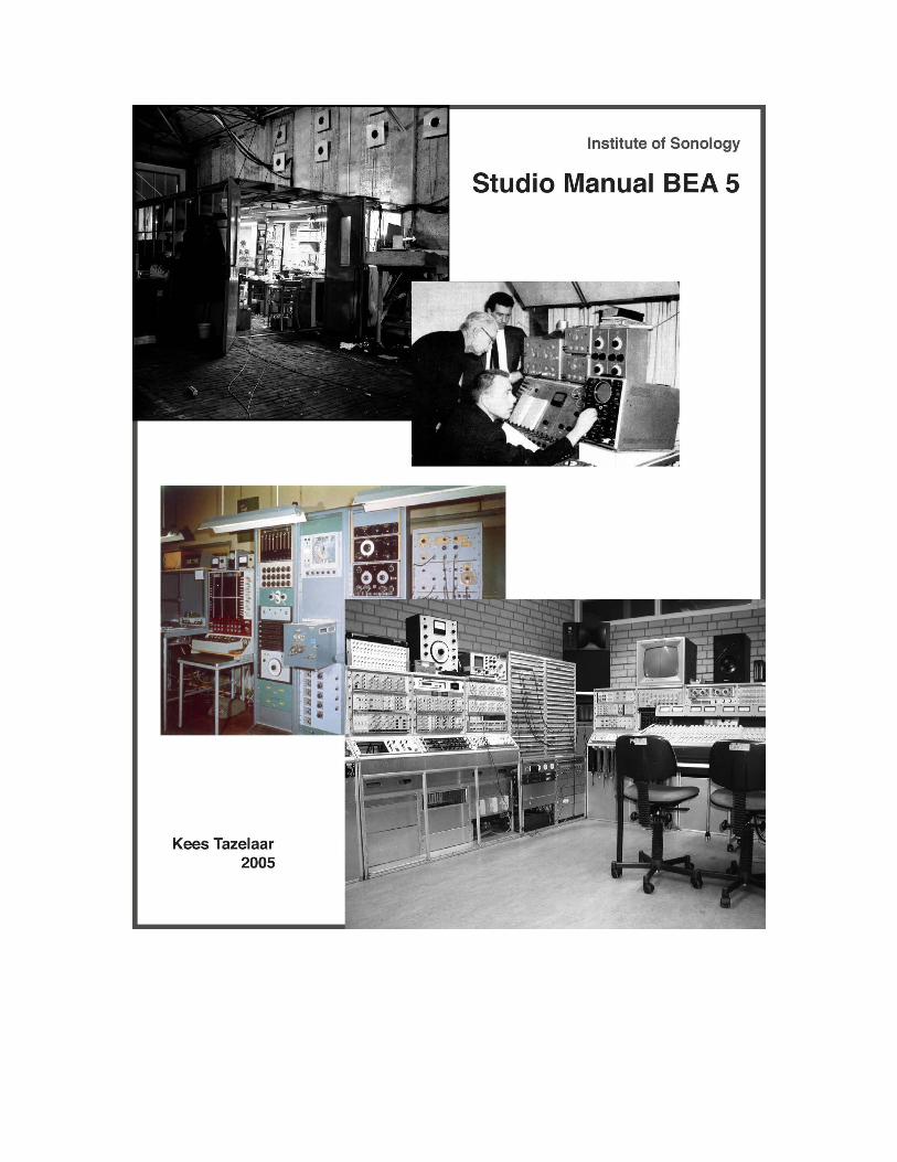

STUDIO MANUAL BEA 5 November 1993 revision 1 November 1995 revision 2 October 1997 revision 3 December 1999 revision 4 August 2005 This studio manual consists of: 1. A general description of the studio. 2. An alphabetic list of the devices. 3. Descriptions of the devices and their functions. 4. Graphical representation of most of the device's outputs. The Analogue Studio that is discussed here is based on the classic voltage controlled studios that were present in the old Institute of Sonology in Utrecht. Most of the devices were designed and built by the Institute, unless indicated otherwise. Generally, the devices in this studio are manually controlled, voltage-controlled (V-), trigger-dependent (T-), or a combination of these (VT-). The configuration in which the devices are used is not fixed, but is completely flexible by making connections on a patching board, where the inputs and outputs of the devices are concentrated. The resulting audio-signals can be recorded on a variety of tape-recorders. Control-voltages can be stored on tape too, but have to be frequency-modulated first. Literature: Jaap Vink/Bill Buxton; Studio Manual. (Institute of Sonology, 1974) Gottfried Michael Koenig; Voltage Control, Diagrams & Circuitry. (Institute of Sonology, 1974)
Kees Tazelaar, August 2005

APPARATUS LIST STUDIO BEA 5 ABBREVIATION AMOUNT NAME OF APPARATUS
ADAT 1 DIGITAL 8-TRACK RECORDER (ALESIS)
AI-1 1 DIGITAL AUDIO INTERFACE FOR ADAT (ALESIS)
ACT 4 AC-TRIGGER
VT-ADSR 4 ATTACK-DECAY-SUSTAIN-RELEASE GENERATOR
AMD 6 AMPLITUDE DEMODULATOR
V-AMM 8 AMPLITUDE MODULATOR
V-BBD 4 BUCKET-BRIGADE DELAY
T-BSC 2 BINARY SCALER
CD 1 COMPACT-DISC PLAYER (DENON)
CNT 1 FREQUENCY COUNTER
COF 4 CORRECTION FILTER
COMP/LIM. 4 COMPRESSOR/LIMITER (BEHRINGER)
DA-500. 2 DIGITAL PATCHBAY and AD-CONVERTER (DENON)
DAT 2 DIGITAL AUDIO TAPE DECK (TASCAM)
DBX 2 DBX I NOISE-SUPPRESSION SYSTEM (DBX)
DCT 4 DC-TRIGGER
T-DIG 1 DOUBLE IMPULSE GENERATOR DVM 4 DIGITAL VOLT-METER
T-ENV 6 ENVELOPE GENERATOR
EQ 4 PARAMETRIC EQUALIZER (BEHRINGER)
T-FFP 4 FLIP-FLOP
V-FILTER 4 VOLTAGE-CONTROLLED FILTER

FRD 4 FREQUENCY DEMODULATOR
V-FUG 16 FUNCTION GENERATOR (NEW MODEL)
HAG 2 HARMONIC GENERATOR
HLF 2 HIGH/LOW FILTER (KROHN&HITE)
V-HLF 2 HIGH/LOW FILTER (SYNTON)
HPA 2 HEADPHONE AMPLIFIER
HPF 2 HIGH-PASS FILTER (ALLISON)
INV 4 INVERTER
V-LPF 2 LOW-PASS FILTER
LPF 2 LOW-PASS FILTER (ALLISON)
LPF 2 LOW-PASS FILTER
MAT 4 MANUAL TRIGGER
MCA 2 MICROPHONE AMPLIFIER MPX-1 1 MULTI-EFFECTS PROCESSOR (LEXICON)
MUP/AMM 8 MULTIPLIER/AMPLITUDE-MODULATOR
MUP/RGM 4 MULTIPLIER/RING-MODULATOR
MXA 8 MIXING AMPLIFIER
OCF 1 OCTAVE-BAND FILTER
PCM-9O 1 DIGITAL REVERBERATOR (LEXICON)
T-PDG 1 PULSE-DELAY GENERATOR
V-PHR 1 PHASER (SYNTON)
T-PRG 1 PSEUDO-RANDOM GENERATOR (H&P)
VT-PWM 4 PULSE-WIDTH MODULATOR
RDF 6 RISE/DECAY FILTER

V-REG 1 RANDOM ENVELOPE GENERATOR V-RPG 1 RANDOM PULSE GENERATOR
VT-SAG 4 SAW-TOOTH GENERATOR
T-SAH 4 SAMPLE-AND-HOLD (with buttons) T-SAH 4 SAMPLE-AND-HOLD (without buttons)
SCOPE 1 OSCILLOSCOPE (2-CHANNEL, SMALL)
SCOPE(LANN) 1 OSCILLOSCOPE (4-CHANNEL, BIG)
SMT 2 SCHMITT TRIGGER
SQG 1 SEQUENCE GENERATOR
SRG 1 SINE/RANDOM GENERATOR (B&K)
V-SWI 2 AC OR DC SWITCH
THF 1 THIRD-OCTAVE BAND FILTER (B&K) V-TMG 4 TENDENCY MASK GENERATOR TUF 1 TUNABLE FILTER (ROHDE&SCHWARZ)
VT-VFG 1 VARIABLE FUNCTION GENERATOR
VLC 4 VARIABLE LEVEL-COMPARATOR
VLC 2 VARIABLE LEVEL-COMPARATOR (+SHIFT)
VT-VOSIM 4 VOICE SIMULATION GENERATOR
T-VSC 8 VARIABLE SCALER
VVS 12 VARIABLE VOLTAGE-SOURCE
V-WIC 2 WINDOW COMPARATOR

ACT The AC-TRIGGER produces a trigger-pulse when the AC-signal applied to the input exceeds a device-dependent level (about -2O dB studio level). The ACT is generally used to synchronise the beginning of an audio signal with the function of some trigger-dependent device. The AC-signal must have a frequency that is higher than 1O Hz. When the reset mode switch is set to "auto", the device resets automatically, each time the input-signal falls below the device's threshold level (with a delay of about O.5 seconds). In the manual reset mode, the device must be reset with a push button before it can fire again. When the input signal is above the threshold-level on the moment of resetting, it fires immediately. Input: audio Output: trigger VT-ADSR The ADSR GENERATOR produces a classic Attack-Decay-Sustain-Release envelope after a pulse is given to the trigger-input. The Gate- Attack- Decay- and Release-times and the Sustain-level can be set on the device or with an external voltage. The device will only respond to a new input-trigger when the gate-time has passed, which is indicated by a red led. Inputs: trigger (T) Gate time (V) Attack (V) Decay (V) Sustain (V) Release (V) Output: envelope (voltage)

AMD The AMPLITUDE DEMODULATOR produces a DC voltage, which is proportional to the amplitude of an audio-signal supplied to the input. The relationship between the audio-amplitude and the DC output is linear. The amplitude of the input-signal may not exceed a level of approx. o dB on the peak-level-meter on the mixing-desk. The speed selector "F" must be set to 4O for normal use. When very fast detection is desired, it must be set to 16O, and for low frequency inputs, it must be set to 1O. Input: audio Output: voltage V-AMM The AMPLITUDE MODULATOR is a device that enables the user to modify the amplitude of an audio-signal by means of manual and/or voltage control. When the potentiometer on the device is closed, the output gain is O with a control-voltage of O volts, and 1 with a control voltage of +5 volts. When however, the manual control is set to give a gain of 1/2, a gain of 1 is already reached with a control- voltage of +2.5 volts (a negative control-voltage of -2.5 volts would result in a gain of O). When the V-AMM is voltage-controlled, the amplitude of the output can be varied very rapidly. If, for example, the control voltage would alternate at a rate of over about 2O Hz, the rapid amplitude modulation would begin to alter the harmonic content of the original signal. For further description of this effect, refer to the chapter "MUP/RGM" in this manual. Inputs: audio (IN) voltage (V) Output: audio V-BBD With the BUCKET-BRIGADE DELAY, it is possible to delay an audio signal between O and 5O milliseconds. The delay time can be controlled with a potentiometer on the device, or with an external control-voltage between O and +5 volts. Inputs: audio (IN) voltage (V) Output: audio

T-BSC The output of the BINARY SCALER can be described as the sum of the voltages produced by 8 independent voltage-supplies, which switch between O volts and a potentiometer-determined maximum, and at a frequency that is a specific division of the trigger-frequency at the input. The numbers written beside the potentiometers, represent the number of input-triggers that are necessary to switch the voltage-supplies on and off one time (= one cycle). The result is a stepwise DC-pattern that can be used as a control-voltage. When the input-frequency is very high, and the output of the T-BSC is connected to the mixing-desk, it will produce an audible block signal that consists of a mix (dependent on the setting of the potentiometers) of 1 to 8 octaves below the input-frequency. Input: trigger (T) Output: voltage (possibly within the audio range)

DBX The DBX noise-reduction system is designed to function in combination with an analogue tape-recorder. It has to be used during recording and playback. Noise that is already present within the audio-signal will not be affected. During the recording, the input signal is compressed before it is stored on the tape (encoding). During playback, the signal is expanded (decoded) with an equal ratio. DBX is effective on the whole audio-spectrum, while Dolby only concerns the higher frequencies. It's because of this, that DBX is much less critical in regard to differences between recording- and playback-characteristics or to tape-exchange between different machines, than it is the case with Dolby. DCT The DC-TRIGGER produces a trigger-pulse each time a device-dependent threshold is crossed (in either direction) by the input-voltage. When the threshold-level (approx. 1.75 volts) is crossed by a rising voltage, the resulting trigger is normally on output 1. When a falling voltage crosses the threshold-level, the resulting trigger is normally on output 2. Other output- configurations can be obtained with a switch on the device. Although the DCT is designed to detect a voltage-control signal, the frequency of the input can be within the audio range. Input: voltage (IN) Outputs: Pulse 1 Pulse 2

T-DIG Activated by an external generator, the DOUBLE IMPULSE-GENERATOR produces two pulses, of which the widths can be determined individually. The delay-time between these pulses can be determined as well. The frequency of the input-triggers can be multiplied by a factor 1, O.1 or O.O1. The maximum pulse-width is O.1, 1, 1O or 1OO milliseconds. The maximum delay-time is 1, 1O, 1OO or 1OOO milliseconds. These maximums can be selected with range-switches. Potentiometers determine the actual values within these ranges. Sine- or triangle-waves can be used to trigger the device, assuming they have minimum amplitude of 5 volts (peak-to-peak) and a frequency that is higher than 2O Hz. Below this frequency only pulse-signals can be used as input. Input: voltage (IN) Output: pulse 1 (possibly within the audio range) pulse 2 (possibly within the audio range) block

T-ENV The output of the ENVELOPE GENERATOR is a DC voltage that changes from O to +5 volts and back to O, each time the device is triggered. The user is able to control, within certain limits, how long the voltage takes to rise to +5 volts, how long it remains there, and how long it takes to fall back to O volts again. These times are referred to respectively as the rise, duration and decay times. Every device consists of two envelope generators, and of one LFO to trigger them. Externally, the generators can be triggered separately. The rise-time starts when the device is triggered, and must lie within the block-time (duration), so that the output is able to reach its maximum value. The decay-time starts as soon as the block-time has ended. If the device is triggered before the decay-time is over, the output will not reach O volts. If the device is triggered again, before the block-time has ended, this trigger is ignored. The duration-potentiometer has a range between O.1 and 2 seconds when the range-switch is in "short" position. When this switch is in "long" position, the range lies between 1 and 2O seconds. Input: trigger (T) Output: voltage

T-FFP The FLIP-FLOP produces block-pulses, of which the "set" and "reset" are determined by separate input-trigger-pulses. These input-pulses may be of a very high frequency. Manual-reset is possible with a push-button on the device. The second output, called "INV", is O volts when the normal output is +5 volts, and vice versa. Input: set (T) reset (T) Output: voltage
FRD The FREQUENCY DEMODULATOR produces a DC voltage that is proportional to the frequency of an audio-signal (between 2O-1OOOO Hz) supplied to the input. A range selector determines the frequency at which the output-voltage reaches +5 volts. When the input-signal has a strong harmonic content, the output-voltage might become unstable, because the device cannot tell the difference between the fundamental frequency and the harmonics. Input: audio (IN) Output: voltage

V-FUG The FUNCTION GENERATOR is a standard generator in the analogue studio. It is capable of producing four basic waveforms: Sine, Triangle, Square, or Pulse. The frequency has a range of 1OOOO Hz, and can be either manually (internal) or voltage controlled (external). The relation between the incoming control voltage and the output frequency can be either linear or exponential. The range-selector specifies the frequency that is produced at the maximum setting of the potentiometer (internal control) or at +5 volts control-voltage. The fine-tuning is useful for instance, when two generators have to be calibrated to one control-voltage. The duty-cycle of the square-output can be controlled manually or by an external voltage. When the generator is used for audio-signals, it has to be switched to AC output. When it is used to produce control voltages, it is normally switched to DC output. Inputs: frequency (V) duty-cycle (V) Output: audio / voltage HAG The HARMONIC GENERATOR starts to produce harmonics, as soon as the input-signal (usually a sine-wave) exceeds a device- dependent level. By further increasing the amplitude, more and more harmonics are produced, while the output-amplitude stays constant. When the input-signal is alternating between a positive and a negative voltage, the harmonics are uneven. When the input-signal is alternating between a positive voltage and O, the harmonics are even. Input: audio (IN) Output: audio INV When the switch on the INVERTER is set at O, the output is a mirrored variant of the input-voltage, the mirror being on the O volts level. In other words, when the input-voltage rises from O to +5 volts, the output falls from O to -5 volts. To shift this output into the normal control-voltage-range, +5 volts can be added by putting the switch into the +5 V position. When a negative voltage has become positive after inversion, it can be shifted back into the negative range by adding -5 volts (switch in the -5 V position). Input: voltage (IN) Output: voltage

V-LPF The VOLTAGE-CONTROLLED LOW-PASS FILTER is a filter of which both the cut-off frequency and the resonance (Q-factor) can be either manually or voltage-controlled. The actual settings of the filter-characteristics are the result of both the manual settings and the level of the control-voltages. The amplitude of the control-voltages can be determined with a second pair of potentiometers. Input: audio (IN) frequency (V) resonance (V) Output: audio MAT The MANUAL TRIGGER generates a trigger-pulse each time a button on the device is pushed. There are four manual triggers built into one unit. Output: pulse MUP/AMM When the switch on this device is in the AMM position, it functions identical to the V-AMM. The audio-signal is expected to be on the X-input, the DC control-voltage must be connected to the Y-input. Full amplitude of the audio-signal is reached at +5 volts control-voltage. In DC-MULTIPLIER mode, one control-voltage can be used to determine the amplitude of a second control-voltage. When both control-voltages are +5 volts, the output is +5 volts too (+5 volts results in a gain of 1, 1 x 5 = 5). When the switch is in the AC-MULTIPLIER position, the function of the device is identical to the MUP/RGM (in multiplier mode). When both input-signals are O dB, the output is O dB too. Inputs: X (audio / voltage) Y (audio / voltage) Output: audio / voltage
MUP/RGM The AC MULTIPLIER and the RING-MODULATOR are housed in one unit and can be selected with a switch. The AC multiplier produces sum- and difference-frequencies (side-bands) from two input- signals. In the case of ring-modulation, these side bands are more complex. The frequency of the input-signals must be higher than 2O Hz and have amplitude that is close to the O dB studio-level. The multiplier has two equivalent inputs, X and Y. The output-signal Z, is the product of X and Y. Given two sine waves, the output Z can be written as Z = sinX x sinY, or Z = sin(X + Y) + sin(X - Y). If one or both of the input-signals are complex, the input in question could be written, according to Fourier, as the sum of single sine-signals. For the output Z, it suffices to state that with each component of the input-signal, sum and difference tones arise with each component of the second input-signal. If X consists of 3 frequencies and Y of 4 frequencies, there will be 3 x 4 = 12 sum- and 12 difference- frequencies. When switched to the ring-modulator mode, the Y input-signal is made into a square-wave, the flanks being formed by every zero-crossover of the input-signal. The complexity of the Y signal is therefore not determined by the shape of the input-signal, but by the regularity with which it crosses zero. The Y signal is used further as in the multiplier-mode. In the case of the Y input being a simple sine, Y becomes a square-wave with the same frequency. According to Fourier, this can be described as: Y = sin a + 1/3 sin 3 a + 1/5 sin 5 a + etc. Inputs: X (audio) Y (audio) Output: audio MXA The MIXING AMPLIFIER is capable of mixing four control-voltages into one output. On a second output, the inversion of this output is available too. With four potentiometers, the individual amplitudes of the inputs can be adjusted. With four switches, the inputs can be multiplied by one, by two, or switched off. When the shift-switch is activated, the potentiometer of channel 4 is used to add a constant voltage (between -5 and +5 volts) to the output. In this situation, the MXA has only three input-channels. When the output exceeds the normal control-voltage-range between -5 and +5 volts, an overload will be indicated by one of the led's. Inputs: channel 1 (V) channel 2 (V) channel 3 (V) channel 4 (V) Output: voltage
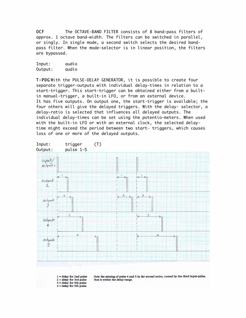
OCF The OCTAVE-BAND FILTER consists of 8 band-pass filters of approx. 1 octave band-width. The filters can be switched in parallel, or singly. In single mode, a second switch selects the desired band- pass filter. When the mode-selector is in linear position, the filters are bypassed. Input: audio Output: audio T-PDG With the PULSE-DELAY GENERATOR, it is possible to create four separate trigger-outputs with individual delay-times in relation to a start-trigger. This start-trigger can be obtained either from a built-in manual-trigger, a built-in LFO, or from an external device. It has five outputs. On output one, the start-trigger is available; the four others will give the delayed triggers. With the delay- selector, a delay-ratio is selected that influences all delayed outputs. The individual delay-times can be set using the potentio-meters. When used with the built-in LFO or with an external clock, the selected delay-time might exceed the period between two start- triggers, which causes loss of one or more of the delayed outputs. Input: trigger (T) Output: pulse 1-5

VT-PWM The PULSE-WIDTH MODULATOR converts trigger-pulses into block-pulses, the duration of which can be determined by voltage- control. The device is designed to function in the audible range. Other waveforms as pulses can also be used to trigger the device, assuming that a threshold-level of +4.5 volts is crossed at a frequency higher than approx. 2 Hz. The maximum pulse-width (at +5 volts control-voltage) is set with the range-switch. Frequency- dividing occurs when the pulse-width exceeds the period between the triggers. In other words, input-triggers that fall within the block- period are ignored. Inputs: trigger (T) pulse-width (V) Output: voltage (possibly within the audio range)

RDF The RISE/DECAY FILTER can continuously modify the rise- and fall-time of a given pulse between O and 1OO Hz, connected to its input. The newly shaped pulse can be used as a control-voltage. The rise- and decay-time can be set with two potentiometers between almost O and 2O seconds. Note, that the rise-time must be within the block-time of the input, to be able to let the output reach its maximum value. The decay-time must be set so, that the output reaches O volts before a new input-pulse is given (unless desired otherwise). Input: voltage (IN) Output: voltage

V-REG The RANDOM ENVELOPE GENERATOR produces 4 random envelopes on individual outputs, the characteristics of which are overall controlled by either the knobs on the device or voltage controls on the inputs. Every envelope has a random rise-time, a random decay-time and a random wait-time. The random values for these parameters fall within ranges that can be set for the individual parameters. A switch selects between an overall slow or fast range. Every envelope additionally produces impulses at the beginning of every new segment (rise, decay, wait). Inputs: minimum rise (V) maximum rise (V) minimum decay (V) maximum decay (V) minimum wait (V) maximum wait (V) Outputs: envelope 1-4 (voltage) pulse rise-start 1-4 (trigger) pulse decay-start 1-4 (trigger) pulse wait-start 1-4 (trigger)

V-RPG The RANDOM PULSE GENERATOR generates eight independently random pulse signals with an overall linear density that is controlled with an external control voltage. On the device, there are two range switches. When the lower switch is in the downward position, the density of the pulses is so high that white noise is produced. The noise on the eight outputs however is still uncorrelated, and when it is reproduced on separate loudspeakers, the spatial impression is completely different from reproducing one noise signal on multiple loudspeakers. With the lower switch in the upward position, the density of the pulses is lowered so that the pulses become audible as separate events. The upper switch can now be used to switch between two ranges of lower densities. It is typical for the design of this generator that simultaneous pulses on two ore more outputs occurs now and then. Input: density (V) Outputs: pulse /noise 1-8 VT-SAG When the SAW-TOOTH GENERATOR is in continuous mode its frequency is controlled with an external voltage between O and 5 volts. A range-switch selects the frequency that is produced at +5 volts control-voltage. In single mode, it produces one saw-tooth pulse every time the device is triggered. The external voltage now controls the width of the waveform. When the pulse-width exceeds the period between two triggers, frequency dividing will occur. Inputs: trigger (T) width (V) Output: voltage (possibly within the audio range)
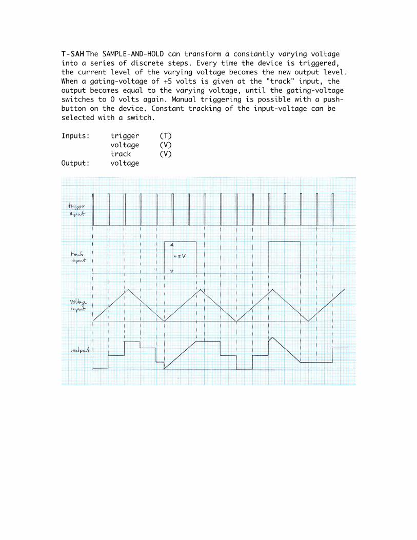
T-SAH The SAMPLE-AND-HOLD can transform a constantly varying voltage into a series of discrete steps. Every time the device is triggered, the current level of the varying voltage becomes the new output level. When a gating-voltage of +5 volts is given at the "track" input, the output becomes equal to the varying voltage, until the gating-voltage switches to O volts again. Manual triggering is possible with a push-button on the device. Constant tracking of the input-voltage can be selected with a switch. Inputs: trigger (T) voltage (V) track (V) Output: voltage

SMT The SCHMITT TRIGGER delivers +5 volts on the output for as long as the amplitude of the input exceeds a user-specified level. Since the SMT has a very fast reaction time, the input can be either audio or DC. When using an audio-signal as input, The SMT produces a block-wave of the same frequency, whose duty-cycle depends on the user-specified threshold-level. Input: audio / voltage (IN) Output: voltage (possibly within the audio range)
SQG The SEQUENCE GENERATOR consists of four voltage-sources, that switch on and off with individual amplitudes and at individual rates (O-5O Hz). With a switch, each source can also be selected to hold the determined maximum (set), or to stay O volts (reset). With the offset-potentiometer, the reset-level can be shifted for all the sources simultaneously. Output: voltage

SRG The SINE/RANDOM GENERATOR (Bruel&Kjaer) was designed as a multi-purpose signal source for electrical and acoustical measurements. It covers a range from 2O to 2OOOO Hz. The following three types of signals can be obtained: sine waves, narrow noise- bands, and white noise. These functions can be selected with the band-width-selector. The frequency, or centre-frequency (in case of narrow noise-bands) can be read of a large scale. (For more elaborate information, read the chapter "SINE/RANDOM GENERATOR" in the old studio-manual). Output: audio V-SWI The VOLTAGE-CONTROLLED SWITCH can switch between two AC and DC signals (depending on the position of the mode-selector) on the basis of a control-voltage. When the control-voltage is between O and 2.5 volts, the first input-signal is selected on the output. When the control-voltage is between 2.5 and 5 volts, the second input-signal is selected. The device can switch between the two signals at a rate of up to about 1OO Hz without distortion. At switching-rates of over about 2O Hz, the two input-signals and the switching-frequency combine to form one complex signal as output. Input: A (audio / voltage) B (audio / voltage) Output: audio / voltage THF The THIRD-OCTAVE BAND FILTER (Bruel&Kjaer) consists of 29 parallel filters. The inputs to these filters are chosen by means of an input-matrix, the outputs of the filters flow via a "programmable" output-matrix. A circuit of 1O potentiometers offers the possibility of mixing 1O arbitrarily chosen spectra with each other. This mixture is available on output one. The outputs two to six are direct outputs, to which filters can be assigned on the output-matrix. (For more elaborate information, read the chapter "THIRD FILTER" in the old studio-manual). Inputs: 1 (audio) 2 (audio) Outputs 1 (audio, potentiometer-field) 2-6 (audio, direct outputs)

V-TMG The TENDENCY MASK GENERATOR produces 4 individual random control voltages of which the individual upper and lower limits can be set on the device or controlled over time by using external control voltages. A “speed” button controls the speed of the random fluctuation for the four outputs simultaneously. The speed can also be controlled externally. Inputs: upper limit 1-4 (V) lower limit 1-4 (V) speed (V) Outputs: random voltage 1-4

VT-VFG The Variable Function Generator is a device that has been available at Sonology in various experimental versions over the years. The version that is recently restored and placed in studio BEA 5 is the last one and was developed at Sonology in 1979-'8O by two students from the HTS Utrecht. The generator produces piece wise constant sequences of twelve steps on nine outputs. The ninth output could be switched internally to control the speed of the shift generator, by which it determines the length of each step (program). The levels of the sequence-steps are adjusted on a 9 X 12 potentiometer-field. The other controls are positioned on a second panel. A. The start-generator. A sequence can be started either with a push-button (MANUAL) or with a trigger on the IN START input (EXTERN). B. The feedback panel. The number of steps in a sequence can be adjusted with a switch between 2 and 12 steps. Two more switches set the sequence-mode: NORMAL, REVERSE or RANDOM. In random mode, the random sequence will always include all steps before a step is repeated. A further series of eight switches determines the number of sequence-repetitions. These 8 switches form a binary code with which you can select every number between 1 and 255. When all of these switches are positioned downwards, the sequence continues until a stop-pulse is given. C. The shift generator panel. On the right there is a selector with the following positions: 1. INT. In this position the shift-pulse is triggered by a built-in generator with a frequency-range of aprox.1OO kHz. 2. EXT. In this position, the same generator is used, but its
frequency is now controlled by an external control-voltage connected to the V-SHFT input. The range-switch still controls the frequency-range of the generator.
3. PROG. As described earlier, it is possible to connect the output of channel nine internally to control the SHFT-frequency.

The position of a potentio-meter on channel nine now determines the length of that particular step.
4. TRIGGER. The shift-pulse can now be triggered externally on the IN SHIFT input, or manually with the push-button on the panel itself. This is especially convenient when setting the voltage levels of the individual steps.
Inputs: start (T) stop (T) shift (T) shift (V) Outputs: channel 1-9 (voltage, possibly within the audio range) step (trigger) E.O.C. (voltage)

VLC The VARIABLE LEVEL-COMPARATOR has two inputs and two outputs. It compares the two incoming voltages and always selects the higher of the two on output one, and the lower on output two. Though this device was designed to function in the low frequency- range, it can also be used to produce complex waveforms in the audio-range. VLC 5 and 6 are a little different, because the second incoming voltage can be shifted with a potentiometer, and it has a high/low output, that can be switched between the high and the low result from the comparison. The other output, called 'comp', is +5 volts when A is higher than B, and O volts when B is higher than A. Inputs: A (V) B (V) Outputs: high (voltage) low (voltage) compare (voltage)

VT-VOSIM The VOSIM GENERATOR that is discussed here is a completely new designed version of an oscillator that produces waveforms according to the classic VoSim model by Kaegi and Tempelaars. On every input-trigger (whose frequency should be in the audible range) the generator produces a series of sine2 pulses, with a frequency that is independent from the trigger-frequency. The amount of sine2 pulses within one period can be set between 1 and 15. Furthermore, an amplitude-decay can be set over the pulse-series that is reset on every new period. The total amplitude of the output can be controlled as well. When setting the amount of pulses (N) and their frequencies, one has to make sure that the complete signal fits into the time between two input-triggers. When this time is exceeded, unwanted side effects such as frequency dividing can occur. For example: When the frequency of the sine2 pulse is 5OOO Hz, and the amount of pulses within one period is 5, the maximum external trigger-frequency is 1OOO Hz. Apart from the trigger, which has to be always external, all parameters can be set either on the device itself or by means of an external voltage. Inputs: start (T) frequency (V) N (V) decay (V) amplitude (V) Output: audio

VVS The VARIABLE VOLTAGE-SOURCE produces a DC voltage that is variable between -5 and +5 volts. On VVS 1-3 and 7-9, the output is determined with normal potentiometers. On VVS 4-6 and 1O-12, this is done with multi-dial potentiometers. These take more time to adjust, but allow accurate and constant settings. Output: voltage V-WIC The WINDOW COMPARATOR produces a pulse-signal, with a duty-cycle that is the result from detection of a fluctuating input- signal. A 'window' is laid on top of this signal, and where the input crosses the limits of the window, the output switches to either the positive or the negative flank of the pulse. The duty-cycle is determined by adjusting the centre and/or the span of the window. This can be done manually with the potentiometers on the device, or externally with two separate control-voltages. The size and position of the window must be within the amplitude of the input-signal. Though this device was designed to function in the low frequency range, it can also be used to produce complex waveforms in the audio-range. Inputs: input (V) center (V) span (V) Output voltage (possibly within the audio range)

Levels in the studio. The reference level in this studio is +4 dBm, which corresponds to the level of the 32O nW test-tone on the CCIR calibration-tape that is used to calibrate the analogue tape-recorders. When this level is recorded or played back, the VU-meters on the analogue recorders and on the meter bridge of the mixing desk indicate O dB. Since the peak-level-meters on the mixing-desk have a much faster response then the VU-meters, they indicate -6 dB for the same level. The reason for this difference is, that in normal musical sound material (as in opposite to a test-tone) there occur very short signal peaks that are allowed to be recorded on a higher level then the reference level of the studio. VU-meters are to slow to monitor these peaks, so on these meters an average recording level around the O dB point gives good results, but on the peak-level-meters, the peaks, that can be recorded at +6 dB are monitored as well, so when they would be calibrated identically, one would tend to record musical material on relatively low levels. By making the peak-level-meters 6 dB less sensitive, both meters should read around O dB during recording. When recording periodic electronic signals however, the difference in sensitivity of the meters has to be taken into account.
Analogue Tape Recorders in BEA 5.
A wide variety of analogue tape recorders are still available in BEA 5. The reasons are, that we have to be able to reproduce tapes that have been made on these recorders and that are stored in our archive, and that for certain purposes in analogue sound production they are preferable to digital recorders.
Recording Levels. It is not possible and forbidden to set recording and playback levels on the analogue tape recorders themselves. These levels have to be adjusted on the mixing desk!
Tape Formats. The standard tape format for stereo recording is 1/4 inch, divided into two tracks. This means, that when you reverse the playback direction, you will hear the same sound in reverse direction. There are two Studer A-807 stereo recorders in the studio with 9.5, 19 and 38 cm/sec (3.75, 7.5 and 15 inch/sec) tape speeds. These recorders can be used with DBX noise reduction systems, which are mounted above them. Please always check the settings of these devices before recording or playing back.
One Studer A-810 is in the studio especially for archive purposes since it is the only machine able of playing back recordings made on 30 IPS. Please do not use this machine unless it is absolutely necessary. For multi-track recording there are two Studer A-8O recorders with four tracks, and one Studer A-8O with eight tracks available. The tape format for these machines is one inch / ½ inch, available tape speeds are 19 and 38 cm/sec (7.5 and 15 inch/sec). What you should know before working with the new ADAT XT 20 recorder. When making a recording on a new tape, one has to make a choice between the best possible sound qualities or compatibility with the older ADAT type I recorders. The ADAT type II format is 20 bit, and can be either of 48 or 44.1kHz sample frequency. It is not possible to play tapes with 20 bit recordings on an ADAT I recorder, but with two ADAT's it is always possible to dither down a 20 bit recording into a 16 bit digital copy. When playing back a 16 bit 44.1kHz-recorded tape in an old ADAT, one has to use the pitch control to correct the playback speed. When working with a tape that was already formatted on an old ADAT recorder, further recordings will automatically be made in ADAT I mode (16 bit 48kHz). A new internal routing function of the input channels is another feature that can cause problems when not fully understood. This function is especially useful when working with mixing desks that have a limited amount of output channels (for instance in the Midi studio). By pressing "Analogue Input" + rec. 1 or 2, the machine switches into the "2-input mode". Input 1 is now routed to channels 1, 3, 5 en 7, and input 2 is routed to channels 2, 4, 6 and 8. By pressing "Analogue Input" + rec. 3 or 4, the machine switches into the "4-input mode". Input 1 is now routed to channels 1 and 5, input 2 is routed to channels 2 and 6, input 3 is routed to channels 3 and 7, and input 4 is routed to channels 4 and 8. By pressing "Analogue Input" and rec. 5,6,7 or 8, the machine switches back to standard "8-input mode". Also new is the possibility to cue and review at three times the normal playback speed. These modes can be selected by pressing the play button together with the rewind or fast forward buttons. Pressing play again will resume normal playback mode. The ADAT XT 20 has 9 locators, which can be stored on the fly and edited later, or entered numerically. Locator 2 and 3 can be used for punch-in and punch-out operations.

To do so, press "Auto-Record". Store punch-in point as locator 2 Store punch-out point as locator 3 Rewind the tape before locator 2 Press play and record simultaneously Recording will start at locator 2, and stop at locator 3. When listening to the recording signals through the ADAT, one now actually listens after the converters, by which eventual distortion caused by overloading of the AD converter can be heard during the recording. More new functions are: Track delay Track copy Improved fast-forward and rewinding speed. Automatic rewinding of a blank tape before formatting.