Embed Size (px)
Citation preview

This quick start guide explains how to quickly set up and activate your McAfee® Network Security Platform NS7100,NS7200, and NS7300 Sensors in in-line mode. These models have a throughput of 1.5 Gbps, 3 Gpbs, and 5 Gbpsrespectively.
All product documentation referenced in this quick start guide is found on the McAfee ServicePortal.
The NS7100/NS7200/NS7300 Sensor model
Figure 1 Sensor front panel
1 Console port (1)
2 RJ-11 port (1) for fail-open control of two built-in SFP+ ports in slot G0. The RJ-11 port supports 1 Gbps (SFP)copper or fiber and 10 Gbps (SFP+) (SR and LR).
3 SFP+ 1/10 Gigabit Ethernet ports (2)
The RJ-11 port controls only the SFP+ 1/10 port pair in passive fail-open mode.
4 Two slots for I/O modules (Any combination of the interface modules can be used.)
• SFP/SFP+ 1/10 GigE Monitoring ports (8)
• RJ-45 10/100/1000 Mbps with internal fail-open Ethernet Monitoring ports (6)
• 10/1 GigE SM 8.5 micron with internal fail-open Monitoring ports (4)
• 10/1 GigE MM 50 micron with internal fail-open Monitoring ports (4)
• 10/1 GigE MM 62.5 micron with internal fail-open Monitoring ports (4)
5 RJ-45 10/100/1000 Mbps Ethernet Monitoring ports (8)
NS7x00 Quick Start GuideRevision D
McAfee Network Security Platform
1

The supported transceiver modules are SFP+ (M2M and SM), SFP Fiber (MM and SM) and SFP Copper.
Figure 2 Sensor rear panel
1 Auxiliary port (1)
2 USB ports (2)
3 Power supply inlet (2)
The NS7x00 Sensors are shipped with one power supply unit. Second power supply (optional) issupported to enable redundancy.
4 RJ-45 10/100/1000 Response port (R1) (1)
5 RJ-45 10/100/1000 Management port (Mgmt) (1)
1 Verify the contents in the box
The following accessories are shipped in the NS7x00 Sensor crate:
• Sensor
• Power cords (McAfee provides standard and international power cables.)
• Set of rack mounting rails
• Printed Quick Start Guide
2 Verify the hardware and software requirements
Make sure to meet the following hardware requirements. For more information, see the McAfee NetworkSecurity Platform Installation Guide.
The following are the system requirements for a Manager server.
2

Minimum required Recommended
Operatingsystem
Any of the following Microsoft operating systems:
• Windows Server 2008 R2 Standard or Enterprise Edition, SP1(Full Installation), English operating system
• Windows Server 2008 R2 Standard or Enterprise Edition, SP1(Full Installation), Japanese operating system
• Windows Server 2012 Standard Edition (Server with a GUI)English operating system
• Windows Server 2012 Standard Edition (Server with a GUI)Japanese operating system
• Windows Server 2012 R2 Standard Edition (Server with a GUI)English operating system
• Windows Server 2012 R2 Standard Edition (Server with a GUI)Japanese operating system
• Windows Server 2012 R2 Datacenter Edition (Server with aGUI) English operating system
• Windows Server 2012 R2 Datacenter Edition (Server with aGUI) Japanese operating system
Only X64 architecture is supported.
Same as the minimumrequired.
Memory 8 GB 8 GB or more
CPU Server model processor such as Intel Xeon Same
Disk space 100 GB 300 GB or more
Network 100 Mbps card 1000 Mbps card
Monitor 32-bit color, 1440 x 900 display setting 1440 x 900 (or higher)
The following are the system requirements for client systems connecting to the Manager application.
Minimum Recommended
Operatingsystem
• Windows 7 English or Japanese
• Windows 8 English or Japanese
• Windows 8.1 English or Japanese
The display language of the Manager client must besame as that of the Manager server operatingsystem.
RAM 2 GB 4 GB
3

Minimum Recommended
CPU 1.5 GHz processor 1.5 GHz or faster
Browser • Microsoft Internet Explorer 9, 10, or 11
• Mozilla Firefox
• Google Chrome (App mode in Windows 8 is notsupported.)
If you are using Google Chrome, add the Managercertificate to the trusted certificate list.
• Internet Explorer 11
• Mozilla Firefox 20.0 orlater
• Google Chrome 24.0 orlater
Install the following software:
• Sensor image
• Manager image
• Signature set
3 Install the slide rails and rack-mount the Sensor
McAfee recommends rack-mounting your Sensor. For maintenance purposes, you must have access to thefront and rear of the Sensor.
Before you mount the Sensor on the rack, make sure that the power is off. Remove the power cableand all network interface cables from the Sensor.
Due to the weight of the appliance, McAfee recommends that two people place the chassis into therail cabinet.
a Disassemble the inner slide rail members from the cabinet sections.
a Pull the inner member out until it comes to a lock position.
b Depress the QD latch to fully disconnect the inner members.
4

b Mount the inner members to the chassis unit.
a Place each inner member on both sides of the chassis unit. Position the bottom mounting holes ofthe inner member with matching mounting holes on chassis unit.
b Use screws to secure inner members in place. Apply to both sides of chassis unit.
c Mount the slide cabinet sections to the rack.
a Install the front end of each slide cabinet section to the rack using the slide tool-less features. Thetool-less latch rotates when the bracket is pressed up against the rack rails.
b Align, adjust, and attach the rear brackets to the rack rail.
5

d Mount the chassis unit into the mounted cabinet sections.
a Guide the chassis unit into the pre-installed cabinet sections. Allow the pre-installed inner membersto slide into the outer members until they lock in place.
b Depress the QD latch on both sides and continue to push the chassis unit in until fully closed.
e Secure the chassis unit through the rack rails.
a With the chassis unit in a fully closed position, secure using two truss head screws.
b Drive the screws through the inner member flange and through the rack rails. The screws threaddirectly to the cabinet slide members. Tighten the screws.
4 Install the interface modules
You can purchase the following interface modules and insert them into the relevant slots on your NS7x00Sensor.
• 8-port SFP/SFP+ 1/10 Gigabit interface module
• 6-port RJ-45 10/100/1000 Mbps with internal fail-open interface module
• 4-port 10/1 GigE SM 8.5 micron with internal fail-open interface module
6

• 4-port 10/1 GigE MM 50 micron with internal fail-open interface module
• 4-port 10/1 GigE MM 62.5 micron with internal fail-open interface module
a Remove the module from its protective packaging.
b Hold the module using your thumb and forefinger and insert it into the modular bay.
c Drive in the screws fixed on the sides of the module to attach it to the Sensor.
5 Connect the Management and Console ports
a On the rear panel of the NS7x00 Sensors, plug a Category 5e Ethernet cable in the Management port(labeled Mgmt).
b Plug the other end of the cable into the network device connected to your Manager server.
7

c On the front panel of the NS7x00 Sensors, plug the DB9 Console cables into the Console port (labeledConsole).
d Connect the other end of the Console port cable directly to a COM port of the PC or terminal server youare using to configure the Sensor (for example, a PC running correctly configured WindowsHyperterminal software). You must directly connect to the console for initial configuration, you cannotconfigure the Sensor remotely.
Terminal servers are provided for console access.
The required settings for Hyperterminal are:
• Baud rate: 115200 • Stop Bits: 1
• Number of Bits: 8 • Control Flow: None
• Parity: None
e Plug one end of the power cable into the power inlet and plug the other end into a power source. TheSensor ships with standard US power and international cables.
The NS-series Sensor does not have a power switch. You can directly plug the power cable intoa power source.
8

6 Connect the monitoring ports
This procedure describes how to connect cables to a Sensor that runs in in-line mode.
a Plug the cable appropriate for use with your transceiver module into one of the monitoring ports labeledx (for example, 1).
b Plug the cable appropriate for use with your transceiver module into one of the monitoring ports labeledy (for example, 2).
c Connect the other end of each cable to the network devices that you want to monitor. For example, if youplan to monitor traffic between a switch and a router, connect the cable connected to 1 to the router andthe one connected to 2 to the switch.
7 Install the Manager software
For detailed instructions, see the McAfee Network Security Platform Installation Guide.
You must have administrator rights on the target Windows Server to install the Manager software.
A MySQL database is included with the Manager and is installed (embedded) automatically on yourtarget Windows Server during this process.
The following steps briefly explain the Manager installation:
a Prepare the system according to the requirements outlined in McAfee Network Security Platform InstallationGuide and the McAfee Network Security Platform Release Notes.
b Close all open applications.
c Go to the McAfee Update Server (https://menshen1.intruvert.com/) and log on, using the grant numberand password.
d Go to the Manager Software Updates folder and select the latest Manager software version available.
e Download the .zip file to the target Windows Server and extract the setup file.
f Double-click Manager _<version>_setup.exe and follow the on-screen prompts.
8 Start the Manager
Click Start | Programs | McAfee | Network Security Manager | Network Security Manager.
9

9 Add the Sensor to the Manager
The Manager displays the Logon page.
a Log on to the Manager using the default user name (admin) and password (admin123).
b Click Devices.
c To add a Sensor in the Manager, click Global | Add and Remove Devices, then click New.
You do not require a license file to enable IPS on NS-series Sensors.
The Add New Device page is displayed. We recommend using the Add Device wizard to add a device.
d Enter the following mandatory information in the appropriate fields.
1) Device Name — The Sensor name must begin with a letter. The maximum length of the name is 25characters.
2) Device Type — Specifies the type of device to be added. Select IPS Sensor.
10

3) Shared Secret — The shared secret must be a minimum of 8 characters and maximum of 25characters in length. The key cannot start with an exclamation mark nor can have any spaces. Theparameters that you can use to define the key are:
• 26 alphabets: Uppercase and lowercase(A, B, C,...Z and a,b,c,...z)
• 32 symbols: ~ ` ! @ # $ % ^ & * ( ) _ + ‑ =[ ] { } \ | ; : " ' , . <? /
• 10 digits: 0 1 2 3 4 5 6 7 8 9
The Sensor name and shared secret key that you enter in the Manager must be identicalto the shared secret that you will later enter during physical installation or initialization ofthe Sensor (using CLI) in Step 10 - Configure Sensor information. If not, the Sensor will not beable to register itself with the Manager.
4) Updating Mode — Select Online or Offline.
Selecting Offline enables Offline Sensor update. Online is the default mode.
e Click Save. The added Sensor is displayed on the Add and Remove Devices page.
10 Configure Sensor information
Configure the Sensor with the network information, a name, and the shared secret key that the Sensor uses toestablish secure communication with the Manager. Use the name and key values you set in Step 9 - Add theSensor to the Manager.
The first time you configure a Sensor, you must have physical access to the Sensor.
At any time during configuration, you can type a question mark (?) to get help on the Sensor CLI commands.For a list of all commands, type commands.
a Log on to the Sensor using the terminal connected to the Console port.
b At the prompt, log on using the default Sensor user name (admin) and password (admin123).
11
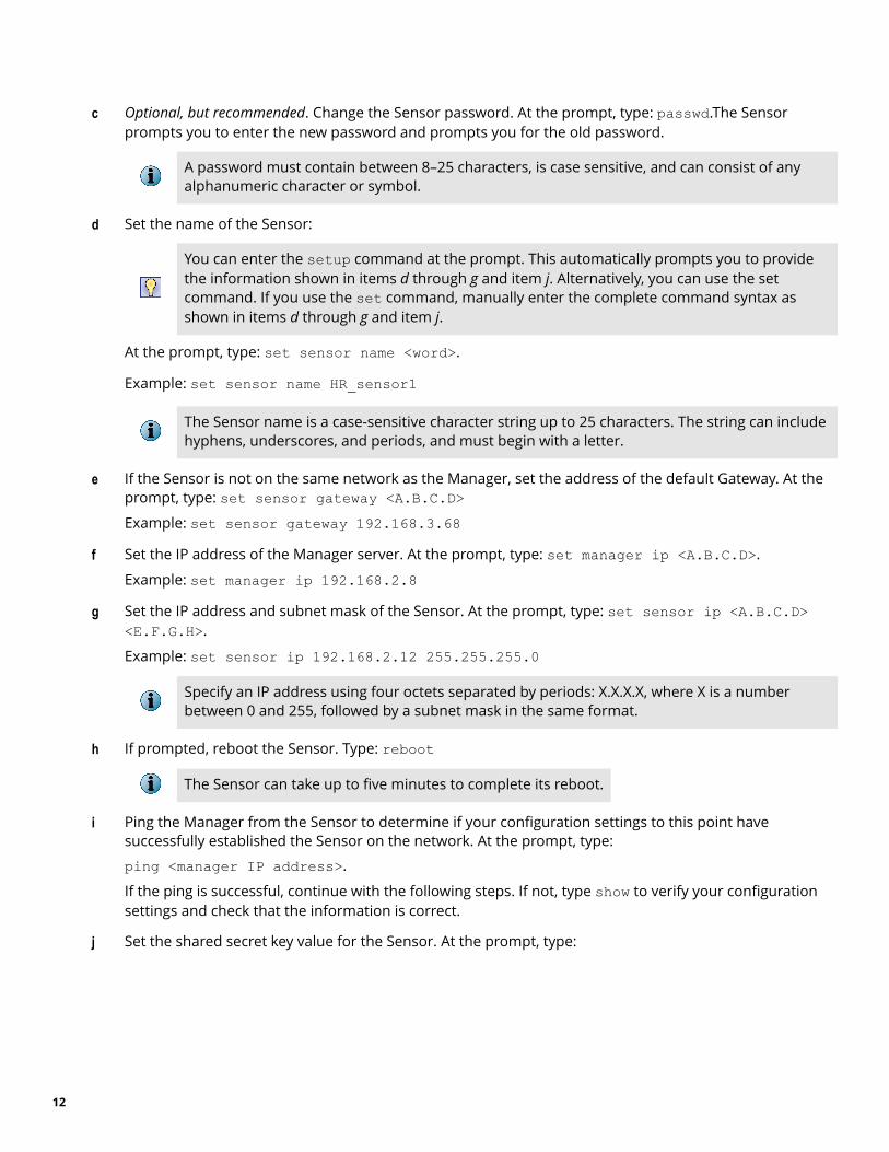
c Optional, but recommended. Change the Sensor password. At the prompt, type: passwd.The Sensorprompts you to enter the new password and prompts you for the old password.
A password must contain between 8–25 characters, is case sensitive, and can consist of anyalphanumeric character or symbol.
d Set the name of the Sensor:
You can enter the setup command at the prompt. This automatically prompts you to providethe information shown in items d through g and item j. Alternatively, you can use the setcommand. If you use the set command, manually enter the complete command syntax asshown in items d through g and item j.
At the prompt, type: set sensor name <word>.
Example: set sensor name HR_sensor1
The Sensor name is a case-sensitive character string up to 25 characters. The string can includehyphens, underscores, and periods, and must begin with a letter.
e If the Sensor is not on the same network as the Manager, set the address of the default Gateway. At theprompt, type: set sensor gateway <A.B.C.D>Example: set sensor gateway 192.168.3.68
f Set the IP address of the Manager server. At the prompt, type: set manager ip <A.B.C.D>.
Example: set manager ip 192.168.2.8
g Set the IP address and subnet mask of the Sensor. At the prompt, type: set sensor ip <A.B.C.D><E.F.G.H>.
Example: set sensor ip 192.168.2.12 255.255.255.0
Specify an IP address using four octets separated by periods: X.X.X.X, where X is a numberbetween 0 and 255, followed by a subnet mask in the same format.
h If prompted, reboot the Sensor. Type: reboot
The Sensor can take up to five minutes to complete its reboot.
i Ping the Manager from the Sensor to determine if your configuration settings to this point havesuccessfully established the Sensor on the network. At the prompt, type:
ping <manager IP address>.
If the ping is successful, continue with the following steps. If not, type show to verify your configurationsettings and check that the information is correct.
j Set the shared secret key value for the Sensor. At the prompt, type:
12

set sensor sharedsecretkeyThe Sensor then prompts you to enter and then confirm the shared secret key value.
This value is used to establish a trust relationship between the Sensor and the Manager. Thesecret key value can be between 8 and 25 characters of any ASCII text. The shared key value iscase-sensitive. Make sure that the value matches the shared secret key value you provided inthe Manager interface in Step 9 - Add the Sensor to the Manager.
k To verify the configuration information, type show. Check that all information is correct.
l To exit the session, type exit.
11 Verify successful installation
a In the Sensor CLI, type: status. The status report is displayed.
The Sensor parameter System Initialized must be yes, and for Manager communication TrustEstablished must be yes.
b From the Manager Dashboard, view the Manager status in the System Health monitor.
13

The Manager status displays as Up and Sensor status is Active.
c From the Manager, click Devices | <Device_Name> | Setup | Physical Ports to open the Physical Ports page.
<Device_Name> indicates the name of the Sensor you added.
d A policy named Default Inline IPS is active upon Sensor addition. To view this policy, select IntrusionPrevention | Policy | IPS Policies. Select Default Inline IPS from the list and click View / Edit.
The Default Inline IPS policy contains attacks already configured with a "blocking" Sensorresponse action. If any attack in the policy is triggered, the Sensor automatically blocks theattack. To tune this or any other McAfee-provided policies, you can clone the policy and thencustomize it as described in the McAfee Network Security Platform IPS Administration Guide.
e Click Devices | <Device_Name> | Setup | Physical Ports.
f Select the port on the Sensor that you cabled to view port settings. Make sure that your port settingsmatch the cabling, for example, if port 1 is cabled for the in-line mode, then the Operating Mode in the portsetting must be in-line mode.
For more information on port settings, see Configuring the monitoring and response ports of aSensor, McAfee Network Security Platform IPS Administration Guide.
14
12 You're up and running!
Your Sensor is actively monitoring connected segments and communicating with the Manager foradministration and management operations.
a For detailed usage instructions, see the McAfee Network Security Platform IPS Administration Guide, or clickthe Detailed Help buttons in the upper-right corner of each window in the Manager.
b Start the Analysis | Threat Analyzer to view alert statistics as attacks are detected. A summary of alerts isdisplayed in the Unacknowledged Alert Summary area of the Manager Dashboard page.
c Having problems? See the McAfee Network Security Platform Troubleshooting Guide for troubleshootinginformation.
d Most deployment problems stem from configuration mismatches between the Sensor and the networkdevices to which it is connected. Check the duplex and auto-negotiation settings on both devices toensure that they are synchronized.
To contact technical support, go to https://support.mcafee.com.
15

Copyright © 2017 McAfee, LLC
McAfee and the McAfee logo are trademarks or registered trademarks of McAfee, LLC or its subsidiaries in the US and other countries. Othermarks and brands may be claimed as the property of others.
16 700-4423D00