Embed Size (px)
Citation preview
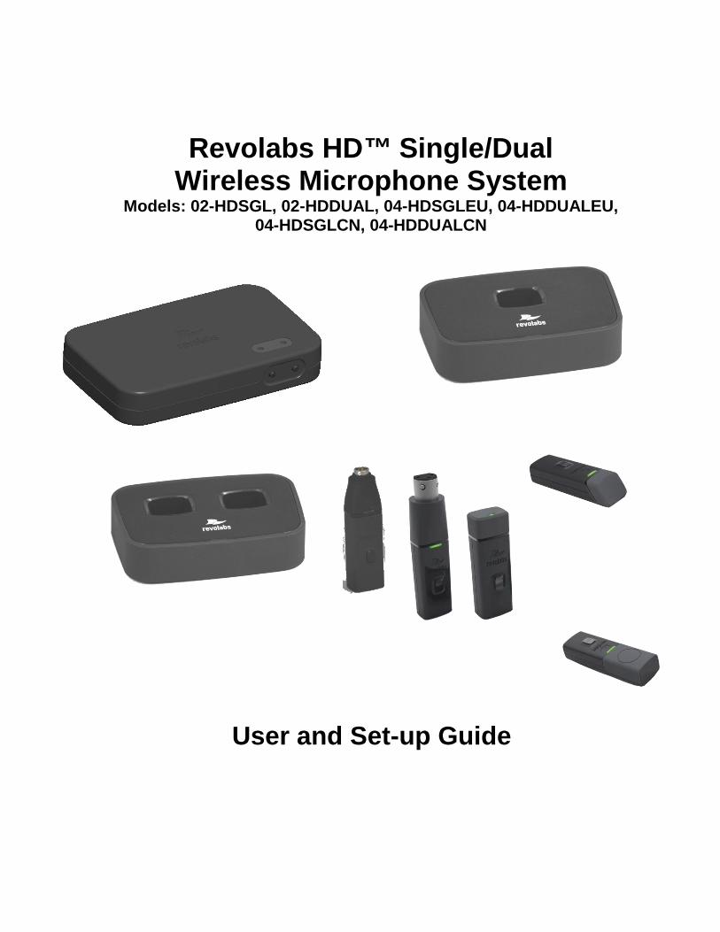
Revolabs HD™ Single/Dual Wireless Microphone System
Models: 02-HDSGL, 02-HDDUAL, 04-HDSGLEU, 04-HDDUALEU, 04-HDSGLCN, 04-HDDUALCN
User and Set-up Guide

© YAMAHA UNIFIED COMMUNICATIONS INC. All rights reserved. No part of this document may be reproduced in any form or by any means without express written permission from Yamaha Unified Communications, Inc. Product specifications are subject to change without notice.
2
Contents Safety and General Information .................................................................................................................... 4 Introduction.................................................................................................................................................... 8
System Components ................................................................................................................................ 8 Installing the Revolabs HD ™ Base Station .................................................................................................. 9
Controls and Connections: ....................................................................................................................... 9 Configuring the Revolabs HDTM Base Station ............................................................................................. 10
Using the Rear Panel Configuration DIP Switches ................................................................................ 11 Using the Revolabs HD Control Panel Software .................................................................................... 12
Revolabs HD Microphones and HD Microphone Adapters ......................................................................... 14 Using the HD Wearable Wireless Microphones ..................................................................................... 14 Using the HD Omni-Directional Tabletop Wireless Boundary Microphones .......................................... 16 Using the HD Directional Tabletop Wireless Boundary Microphones .................................................... 17 Using the HD XLR Microphone Wireless Adapter .................................................................................. 18 Using the HD Wireless Adapter for Countryman Microphone ................................................................ 19 Pairing Wireless Microphones to Base Station....................................................................................... 20
Revolabs HDTM Single or Dual Charger Base............................................................................................. 21 Power Module ......................................................................................................................................... 22 Charging the Microphone Batteries ........................................................................................................ 22
Updating the Revolabs HDTM Firmware ...................................................................................................... 22 Revolabs HD™ Indicator LEDs ................................................................................................................... 24 Warranty ...................................................................................................................................................... 25 Specifications .............................................................................................................................................. 26 Index ............................................................................................................................................................ 27
3
Safety and General Information Please read the following information to ensure safe and efficient use of your Revolabs system.
FCC User Information
FCC ID: T5V02HDDUALNM Revolabs HD™ Dual Base Station
FCC ID: T5V0HDEXEMIC Revolabs Executive HD ™ Microphone
FCC Notice to Users This device complies with Part 15 of the FCC Rules. Operation is subject to the following two conditions: (1) this device may not cause harmful interference, and (2) this device must accept any interference received, including interference that may cause undesired operation.
Users are not permitted to make changes or modify the equipment in any way. Changes or modifications not expressly approved by Yamaha Unified Communications, Inc. could void your authority to operate this equipment under Federal Communications Commission’s rules.
. RADIO AND TELEVISION INTERFERENCE This equipment has been tested and found to comply with the limits for a Class B digital device, pursuant to Part 15 of the FCC rules. These limits are designed to provide reasonable protection against harmful interference in a residential installation. This equipment generates, uses and can radiate radio frequency energy and, if not installed and used in accordance with the instructions, may cause harmful interference to radio communications. However, there is no guarantee that interference will not occur in a particular installation. If this equipment does cause harmful interference to radio or television reception, which can be determined by turning the equipment off and on, the user is encouraged to try to correct the interference by one or more of the following measures:
- Reorient or relocate the receiving antenna.
- Increase the separation between the equipment and the receiver.
- Connect the equipment into an outlet on a circuit different from that to which the receiver is connected.
- Consult the dealer or an experienced radio/TV technician for help.
You may also find helpful the following booklet, prepared by the FCC: "How to Identify and Resolve Radio-TV Interference Problems." This booklet is available from the U.S. Government Printing Office, Washington D.C. 20402.
4
Industry Canada Notice to Users This Class B digital apparatus complies with Canadian ICES-003.
Operation is subject to the following two conditions:
(1) This device may not cause interference and
(2) This device must accept any interference, including interference that may cause undesired operation of thedevice
Le présent appareil est conforme aux CNR d'Industrie Canada applicables aux appareils radio exempts de licence. L'exploitation est autorisée aux deux conditions suivantes : (1) l'appareil ne doit pas produire de brouillage, et (2) l'utilisateur de l'appareil doit accepter tout brouillage radioélectrique subi, même si le brouillage est susceptible d'en compromettre le fonctionnement.
IC 6455A-01HDEXEC Revolabs HD™ Dual Base Station
IC: 6455A-0HDEXEMIC Revolabs Executive HD ™ Microphone
RF Exposure: This equipment complies with FCC radiation exposure limits set forth for an uncontrolled environment. The antenna(s) used for this equipment must be installed to provide a separation distance of at least eight inches (20 cm) from all persons. This equipment must not be operated in conjunction with any other antenna.
This device complies with RF exposure requirements in Industry Canada RSS-102 Issue 4.
For Body Worn Operation: SAR data information for residents in countries that have adopted the SAR limit recommended by the International Commission of Non-Ionizing Radiation Protection (ICNIRP), which is 0.08 W/kg averaged over the whole body or 2.00 W/kg averaged over ten (10) gram of tissue (for example European Union, Japan, Brazil and New Zealand): The highest SAR value for this product when tested for use on the body is 0.35 W/kg (averaged over 10g).
Professional Installation Recommended This product should be professionally installed.
Notice to Customers in Australia
• Do not use the areas where there are explosive hazards
• Do not use in environments where there is a danger of ignition of flammable gasses.
Restricted use with certain medical devices Hearing Aids Some devices may interfere with some hearing aids. In the event of such interference, you may want to consult with your hearing aid manufacturer to discuss alternatives.
Other Medical Devices If you use any other personal medical device, consult the manufacturer of your device to determine if it is adequately shielded from RF energy. Your physician may be able to assist you in obtaining this information.
5
Export Law Assurances This product is controlled under the export regulations of the United States of America and Canada. The Governments of the United States of America and Canada may restrict the exportation or re-exportation of this product to certain destinations. For further information contact the U.S. Department of Commerce or the Canadian Department of Foreign Affairs and International Trade. The use of wireless devices and their accessories may be prohibited or restricted in certain areas. Always obey the laws and regulations on the use of these products.
02-HDSGL and 02-HDDUAL (1 & 2 channel systems respectively) North AmericaUPCS Usage RestrictionDue to the UPCS frequencies used, this product is licensed for operation only in the United States of America and Canada.
04-HDSGLEU and 04-HDDUALEU (1 & 2 channel systems respectively) EuropeanUnion Usage RestrictionDue to the DECT frequencies used, this product is licensed for operation only in the European Union countries including Australia.
Notice to European Customers
Yamaha UC EMEA190 High StreetTonbridge, Kent
TN9 1BE, UK+44 (0)1732 366535
Declare that for the hereinafter mentioned product model numbers, the presumption of conformity with the applicable essential requirements has been approved in accordance with Council Directive 1999/5/EC
“Radio and Telecommunications Terminal Equipment” and RoHS II Directive 2011/65/EU. 04-HDSGLEU-NM HD Single Channel System, 1-Channel, w/o mics 04-HDDUALEU-NM HD Dual Channel System 2-Channel, w/o mics 03-HDEXEMICEU-11 HD Microphone, Wearable 03-HDTBLMICEU-OM-11 HD Microphone, Tabletop, Omni-directional03-HDTBLMICEU-DR-11 HD Microphone, Tabletop, Directional03-HDXLRMICEU-11 HD, XLR Wireless Adapter for Dynamic Handheld Microphone 03-HDCOMANEU-11 HD Wireless Adapter for Countryman Microphone
Any unauthorized modification of the products voids this Declaration. For a copy of the original signed declaration of conformity, please contact Yamaha UC EMEA at the above address.
6

WEEE Notification:
The Waste Electrical and Electronic Equipment (WEEE) directive (2012/19/EU) is intended to promote recycling of electrical and electronic equipment and their components at end of life.
According to the requirement of the WEEE legislation the following user information is provided to customers for all branded Revolabs products subject to the WEEE directive.
“The symbol on the product or its packaging indicates that this product must not be disposed of with your other household waste. Instead, it is your responsibility to dispose of your waste equipment by handing it over to a designated collection point for the recycling of waste electrical and electronic equipment. The separate collection and recycling of your waste equipment at the time of disposal will help conserve natural resources and ensure that it is recycled in a manner that protects human health and the environment. For more information about where you can drop off your waste for recycling, please contact your local authority, or where you purchased your product.”
7
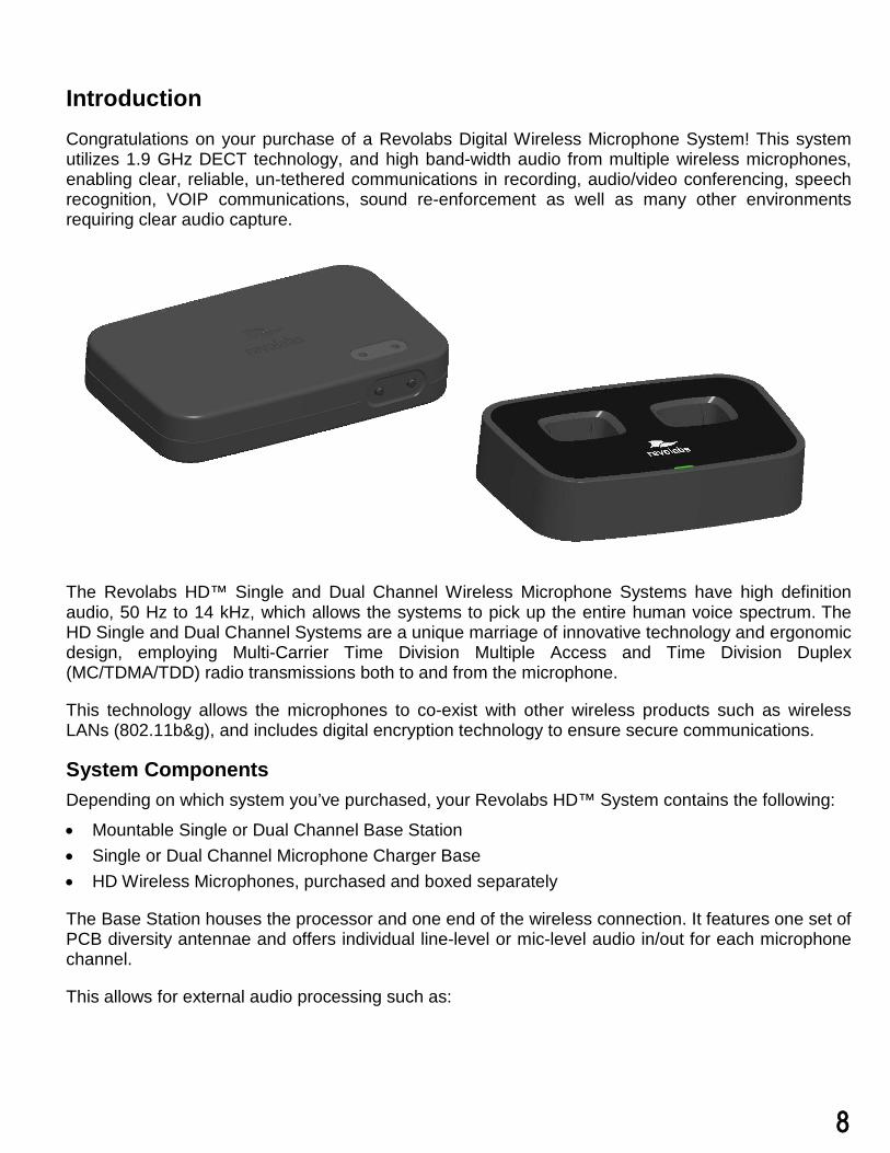
Introduction Congratulations on your purchase of a Revolabs Digital Wireless Microphone System! This system utilizes 1.9 GHz DECT technology, and high band-width audio from multiple wireless microphones, enabling clear, reliable, un-tethered communications in recording, audio/video conferencing, speech recognition, VOIP communications, sound re-enforcement as well as many other environments requiring clear audio capture.
The Revolabs HD™ Single and Dual Channel Wireless Microphone Systems have high definition audio, 50 Hz to 14 kHz, which allows the systems to pick up the entire human voice spectrum. The HD Single and Dual Channel Systems are a unique marriage of innovative technology and ergonomic design, employing Multi-Carrier Time Division Multiple Access and Time Division Duplex (MC/TDMA/TDD) radio transmissions both to and from the microphone.
This technology allows the microphones to co-exist with other wireless products such as wireless LANs (802.11b&g), and includes digital encryption technology to ensure secure communications.
System Components Depending on which system you’ve purchased, your Revolabs HD™ System contains the following:
• Mountable Single or Dual Channel Base Station• Single or Dual Channel Microphone Charger Base• HD Wireless Microphones, purchased and boxed separately
The Base Station houses the processor and one end of the wireless connection. It features one set of PCB diversity antennae and offers individual line-level or mic-level audio in/out for each microphone channel.
This allows for external audio processing such as:
8
• Acoustic echo cancellation (AEC)• Feedback elimination• Level control• Equalization• Noise cancellation
The system is designed to optimize audio capture/reproduction by providing: • Consistent audio input from all participants• Minimum room noise• Mute control• Wireless encryption• Automatic channel selection• Full duplex audio
The Charger Base charges the HD Wireless Microphones and stores them when not in use.
Installing the Revolabs HD ™ Base Station
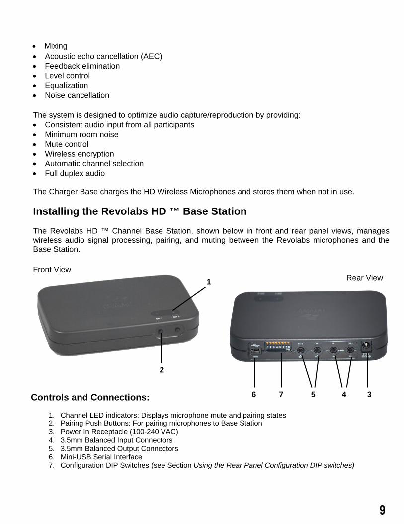
The Revolabs HD ™ Channel Base Station, shown below in front and rear panel views, manages wireless audio signal processing, pairing, and muting between the Revolabs microphones and the Base Station.
Front View Rear View
Controls and Connections:
1. Channel LED indicators: Displays microphone mute and pairing states2. Pairing Push Buttons: For pairing microphones to Base Station3. Power In Receptacle (100-240 VAC)4. 3.5mm Balanced Input Connectors5. 3.5mm Balanced Output Connectors6. Mini-USB Serial Interface7. Configuration DIP Switches (see Section Using the Rear Panel Configuration DIP switches)
1
2
3456 7
• Mixing
9
To Install the Base Station:
1. Plug the power cord into an appropriate outlet2. Connect the necessary outputs and inputs
Revolabs HD™ Base Station Audio Connections There are (2) 3.5mm balanced inputs and (2) 3.5mm balanced outputs on the back panel of the unit providing access to each channel’s audio signal.
The three terminals correspond to:
Tip = Positive + Ring = Negative – Sleeve = Shielded Ground
There are one or two output channels representing a separate channel for each microphone. The microphone output connectors need to be attached to the input connectors of an audio mixer.
The Base Station input connectors (also 0 dBu) may then be attached to mixer channel outputs. Because the system is full-duplex, the input connections provide the ability to hear program audio using a 2.5mm earpiece attached to the microphone (supplied with the wearable microphone). Depending on the application, it is possible to feed a single audio feed back to each earpiece. This would allow for translation, personal hearing assistance or other services to be incorporated into an application.
NOTE: The USB port may exhibit static sensitivity. If the Base Station audio shuts down after handling, please power cycle the Base Station
Note: The HD Single/Dual System is not compatible with any other Revolabs system and therefore cannot be installed in the same room. The HD and Solo Wireless Microphones and Charger Bases are not interchangeable. No more than one HD Single/Dual system can be used in a single room. Please contact [email protected] for design recommendations.
Configuring the Revolabs HDTM Base Station
Each Revolabs HDTM Base Station must be configured properly prior to use. Accurate configuration is dependent on several variables such as:
• Is Line Level or Mic Level signal required?Refer to setting Dip Switch 3 below.
• How many HDTM Dual/Single Systems are being used together in close proximity?If you have more than one Revolabs Wireless Microphone System, refer to setting DipSwitch 7&8 below. Note: It is recommended that the lowest functioning Transmit Powerbe used for each system.
• How large is the room?Refer to setting Dip Switch 7&8 below. Note: It is recommended that the lowestfunctioning Transmit Power be used for each system.
10
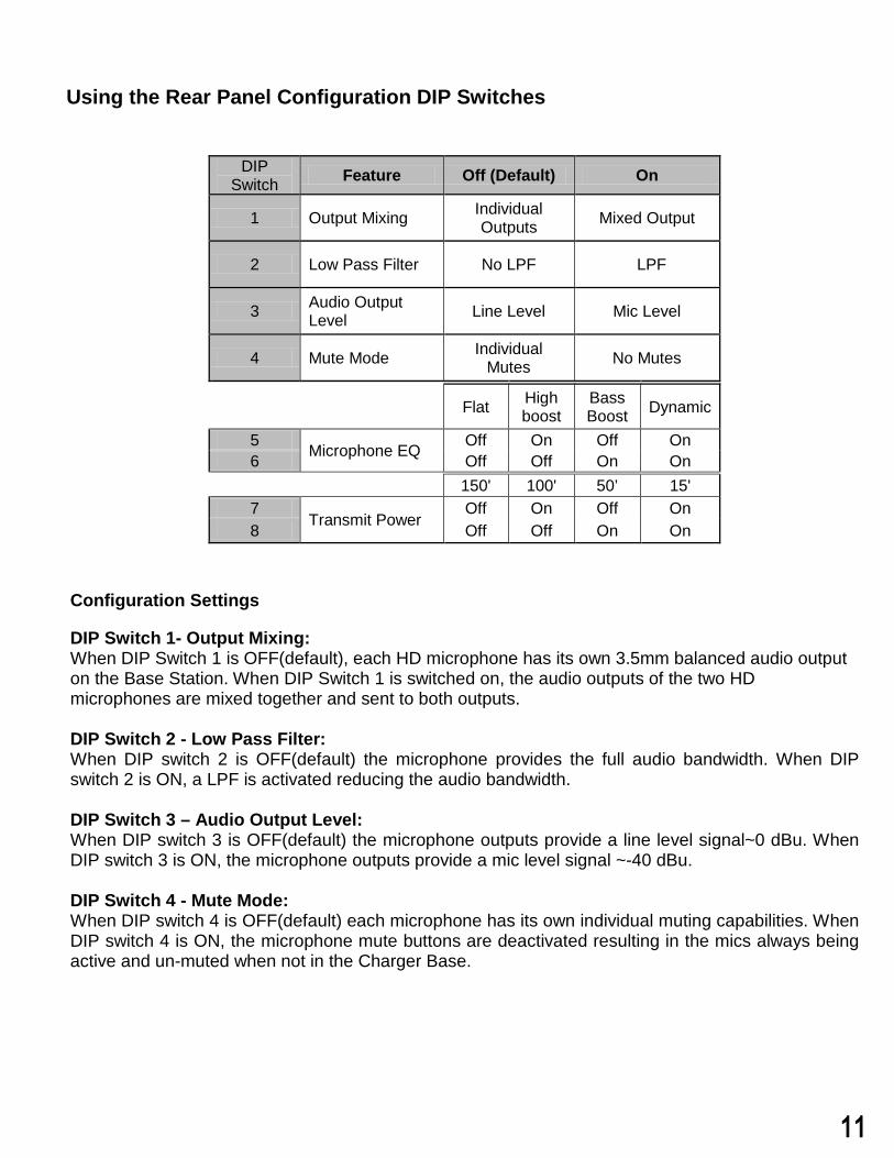
Using the Rear Panel Configuration DIP Switches
DIP Switch Feature Off (Default) On
1 Output Mixing Individual Outputs Mixed Output
2 Low Pass Filter No LPF LPF
3 Audio Output Level Line Level Mic Level
4 Mute Mode Individual Mutes No Mutes
Flat High boost
Bass Boost Dynamic
5 Microphone EQ Off On Off On 6 Off Off On On
150' 100' 50’ 15' 7
Transmit Power Off On Off On
8 Off Off On On
Configuration Settings
DIP Switch 1- Output Mixing: When DIP Switch 1 is OFF(default), each HD microphone has its own 3.5mm balanced audio output on the Base Station. When DIP Switch 1 is switched on, the audio outputs of the two HD microphones are mixed together and sent to both outputs.
DIP Switch 2 - Low Pass Filter: When DIP switch 2 is OFF(default) the microphone provides the full audio bandwidth. When DIP switch 2 is ON, a LPF is activated reducing the audio bandwidth.
DIP Switch 3 – Audio Output Level: When DIP switch 3 is OFF(default) the microphone outputs provide a line level signal~0 dBu. When DIP switch 3 is ON, the microphone outputs provide a mic level signal ~-40 dBu.
DIP Switch 4 - Mute Mode: When DIP switch 4 is OFF(default) each microphone has its own individual muting capabilities. When DIP switch 4 is ON, the microphone mute buttons are deactivated resulting in the mics always being active and un-muted when not in the Charger Base.
11

DIP Switch 5&6 – Microphone EQ: There are four EQ options for the microphone outputs of the Base Station. One of these options can be activated for both microphones.
DIP Switch 7&8 - Transmit Power: The transmit power of the Base Station can be adjusted to help reduce the operational radius of a Revolabs HDTM System in order to prevent interference from other Revolabs products, or from other devices operating in the same frequency.
Note: It is recommended that the lowest functioning Transmit Power be used for each system. Actual range depends on RF signal absorption, reflection, and interference.
Using the Revolabs HD Control Panel Software A software program with graphical user interface is available for accessing control settings and real-time status of Revolabs HD Microphone Systems. A detailed description of how to use this tool is described below.
1. Download the Revolabs HD Control Panel software from www.uc.yamaha.com/downloads
2. Connect the PC to the HD Single/Dual Base Station via USB.3. Allow the PC to recognize the hardware and install the necessary drivers.4. Install the software downloaded in Step 1, which requires Windows 2000, NT, Vista, or 7.5. Launch the Revolabs HD Control Panel program.
Configuration Settings
The Revolabs HD Control Panel controls most of the HD Single/Dual Base Station configuration settings. It also provides real time status of the microphones. Only one HD Single/Dual system can be controlled and monitored from a single PC at any given time.
12
Mics Unmute at Startup: By default the mics go into a muted state when they are removed from the charger. This is done to prevent handling noise as the microphone is placed into position. By selecting ‘Mics Unmuted at Startup’, the mics will go into an unmuted state when removed from the charger.
All Mic Mute: This feature removes the mics individual mute capability and causes both microphones to mute when the mute button on either microphone is pressed. The same effect will take place when unmuting the microphones.
Note: Any changes to ‘Mics Unmute at Startup’ or ‘All Mic Mute’ requires the ‘Save’ button to be pressed in order for the changes to take effect.
Lock: Each microphone has individual lock capabilities. By turning on the lock for a specific microphone, the microphone mute button will deactivate leaving the user without the ability to individually control the microphones mute status at the microphone. However, the HD Control Panel Software will still have the ability to control and monitor all locked microphones.
Note: A microphone lock is stored in the Base Station. If a new microphone is paired to a locked channel, that microphone will then be locked as well. The same goes for a locked microphone that is paired to an unlocked channel, that microphone will then be unlocked.
Mute: Each microphone has individual mute capabilities. The HD Control Panel Software provides the user the ability to mute and unmute a microphone from their PC. These mute controls will always remain synchronized to the actual state of the microphone. If the microphone state is changed at the microphone, the mute controls will display that change.
Gain: Each microphone has an individual gain fader. This fader provides +/- 10dB of gain in 5dB increments. The microphone gains are stored in the Base Station and will be applied to any microphone paired to that channel.
Status: This provides the current status for the microphone paired to each channel. The status can read any of the following states:
Type: This provides the current type for the microphone that is paired to each channel.
Version: This provides the current firmware version for the microphone that is paired to each channel.
OFF = Microphone is has been turned off ON = Microphone is on and operational
CHRG = Microphone is in the Charging Base OUT = Microphone is out of range and cannot communicate
13
Note: The microphone firmware version must match the Base firmware version for the system to function properly. A mismatch may result in no audio from the microphones.
Battery: This provides the current battery level for the microphone that is paired to each channel and active. The value changes in 12.5% increments and represents the bottom of the range the battery is in. Therefore a value of 87% means that the battery level is between 87%-100%.
Pairing: This provides the ability to activate pairing mode for the respective base station channel. It also provides the pairing status of any base station channel already in pairing mode.
Firmware: This window provides the current firmware versions found in the Base Station and microphones as well as provides the HD Firmware Loader for loading the firmware to the base station and microphones.
DIP Switches: This displays the current state of the base station DIP switches. When a DIP switch is in the ‘OFF’ position the DIP function will remain “greyed out”. When a DIP switch is in the ‘ON’ position, the functionality of that DIP switch will change to BLACK to indicated that the feature is active.
Revolabs HD Microphones and HD Microphone Adapters Use any of five microphones with your Revolabs HD ™ System:
• Revolabs HD Wearable Wireless Microphone• Revolabs HD Omni-directional Tabletop Wireless Boundary Microphone• Revolabs HD Uni-directional Tabletop Wireless Boundary Microphone• Revolabs HD Universal Wireless Adapter for Handheld Microphones• Revolabs HD Wireless Adapter for Countryman Microphones
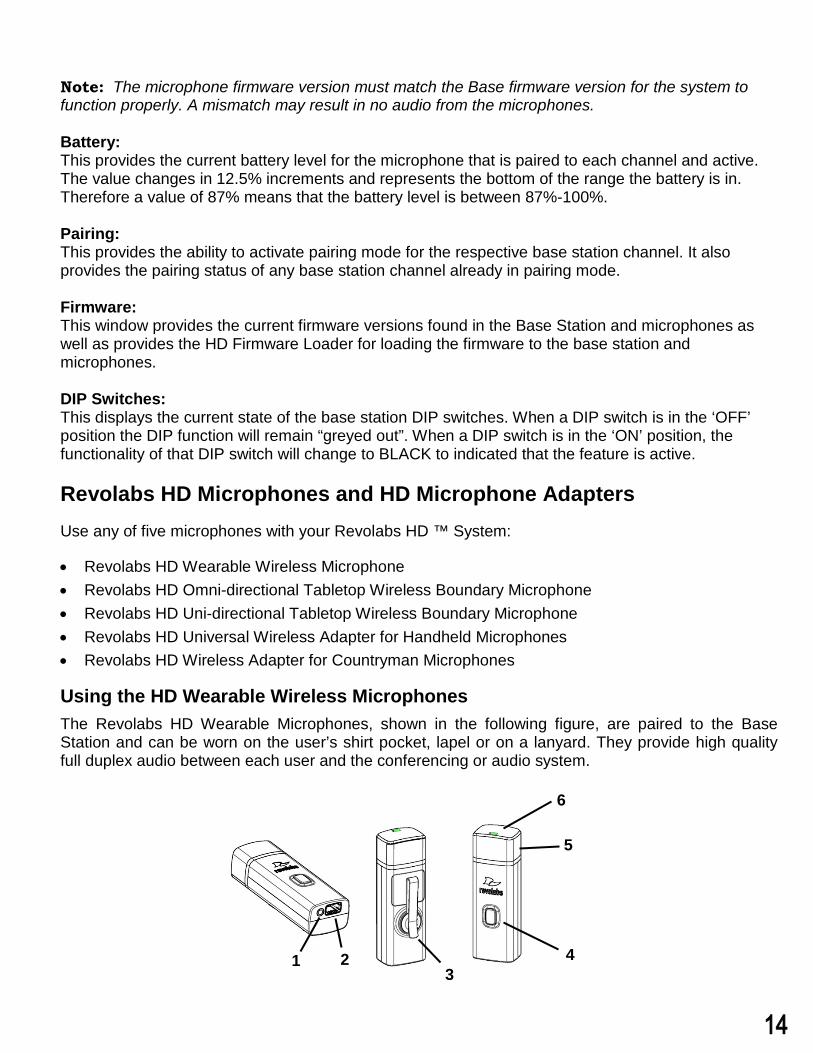
Using the HD Wearable Wireless MicrophonesThe Revolabs HD Wearable Microphones, shown in the following figure, are paired to the Base Station and can be worn on the user’s shirt pocket, lapel or on a lanyard. They provide high quality full duplex audio between each user and the conferencing or audio system.
4
6
5
321
14
1. Earpiece jack — accepts the 2.5mm plug for the earpiece.2. Charging port — docks to Revolabs HD Charger Bases.3. Pocket clip — also used to attach microphone to a lapel, blouse or lanyard.4. Mute Button — press to mute, un-mute and pair microphone.5. Acoustic Cover — protects delicate microphone element (non-removable).6. LED display — visual status for mute, un-mute, and pairing.
Note: Microphones in new systems must be paired to the Base Station with each microphone assigned to a unique channel on the base unit. See pairing instructions below.
Revolabs HD Wearable Microphones turn on and mute automatically when removed from Charger Base, to reduce noise while being attached.
To use the HD Wearable Microphone:
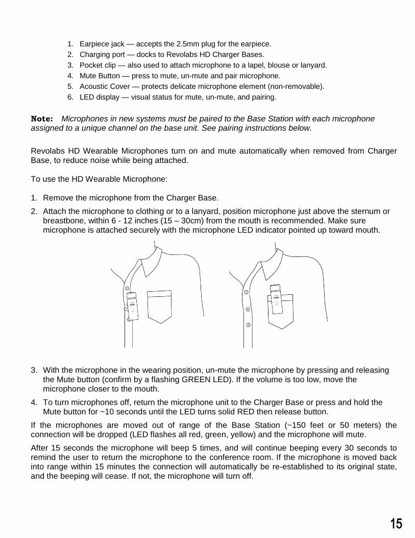
1. Remove the microphone from the Charger Base.2. Attach the microphone to clothing or to a lanyard, position microphone just above the sternum or
breastbone, within 6 - 12 inches (15 – 30cm) from the mouth is recommended. Make suremicrophone is attached securely with the microphone LED indicator pointed up toward mouth.
3. With the microphone in the wearing position, un-mute the microphone by pressing and releasingthe Mute button (confirm by a flashing GREEN LED). If the volume is too low, move themicrophone closer to the mouth.
4. To turn microphones off, return the microphone unit to the Charger Base or press and hold theMute button for ~10 seconds until the LED turns solid RED then release button.
If the microphones are moved out of range of the Base Station (~150 feet or 50 meters) the connection will be dropped (LED flashes all red, green, yellow) and the microphone will mute. After 15 seconds the microphone will beep 5 times, and will continue beeping every 30 seconds to remind the user to return the microphone to the conference room. If the microphone is moved back into range within 15 minutes the connection will automatically be re-established to its original state, and the beeping will cease. If not, the microphone will turn off.
15
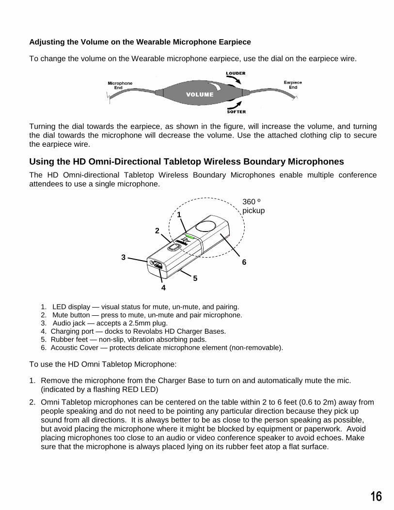
Adjusting the Volume on the Wearable Microphone Earpiece
To change the volume on the Wearable microphone earpiece, use the dial on the earpiece wire.
Turning the dial towards the earpiece, as shown in the figure, will increase the volume, and turning the dial towards the microphone will decrease the volume. Use the attached clothing clip to secure the earpiece wire.
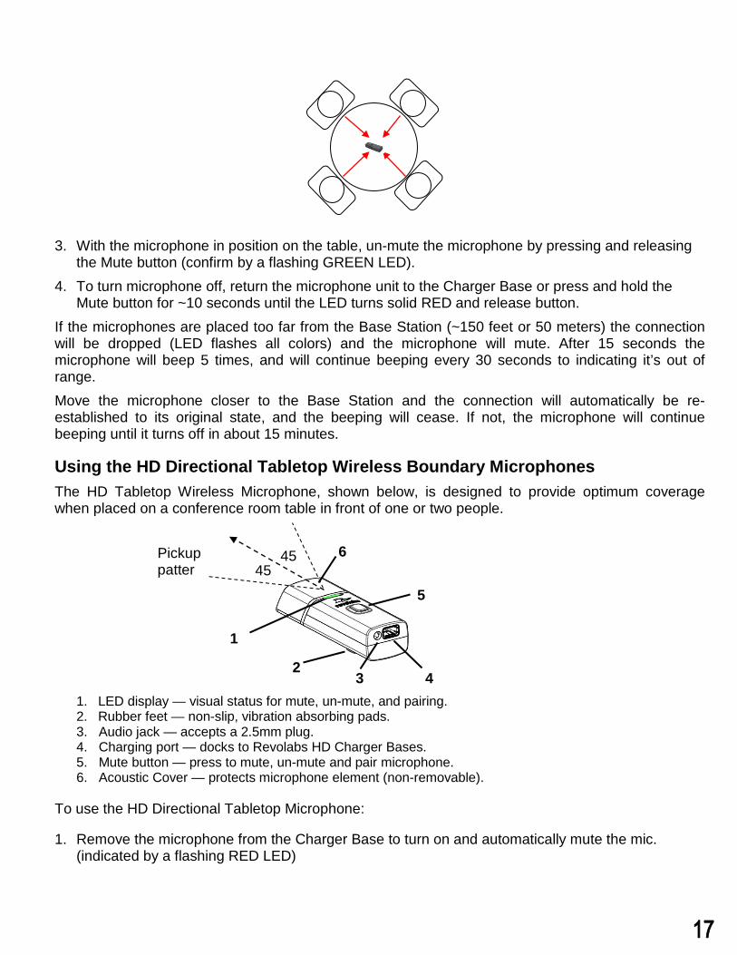
Using the HD Omni-Directional Tabletop Wireless Boundary Microphones The HD Omni-directional Tabletop Wireless Boundary Microphones enable multiple conference attendees to use a single microphone.
1. LED display — visual status for mute, un-mute, and pairing.2. Mute button — press to mute, un-mute and pair microphone.3. Audio jack — accepts a 2.5mm plug.4. Charging port — docks to Revolabs HD Charger Bases.5. Rubber feet — non-slip, vibration absorbing pads.6. Acoustic Cover — protects delicate microphone element (non-removable).
To use the HD Omni Tabletop Microphone:
1. Remove the microphone from the Charger Base to turn on and automatically mute the mic.(indicated by a flashing RED LED)
2. Omni Tabletop microphones can be centered on the table within 2 to 6 feet (0.6 to 2m) away frompeople speaking and do not need to be pointing any particular direction because they pick upsound from all directions. It is always better to be as close to the person speaking as possible,but avoid placing the microphone where it might be blocked by equipment or paperwork. Avoidplacing microphones too close to an audio or video conference speaker to avoid echoes. Makesure that the microphone is always placed lying on its rubber feet atop a flat surface.
6
2
3
1
45
360 º pickup
tt
16
3. With the microphone in position on the table, un-mute the microphone by pressing and releasingthe Mute button (confirm by a flashing GREEN LED).
4. To turn microphone off, return the microphone unit to the Charger Base or press and hold theMute button for ~10 seconds until the LED turns solid RED and release button.
If the microphones are placed too far from the Base Station (~150 feet or 50 meters) the connection will be dropped (LED flashes all colors) and the microphone will mute. After 15 seconds the microphone will beep 5 times, and will continue beeping every 30 seconds to indicating it’s out of range. Move the microphone closer to the Base Station and the connection will automatically be re-established to its original state, and the beeping will cease. If not, the microphone will continue beeping until it turns off in about 15 minutes.
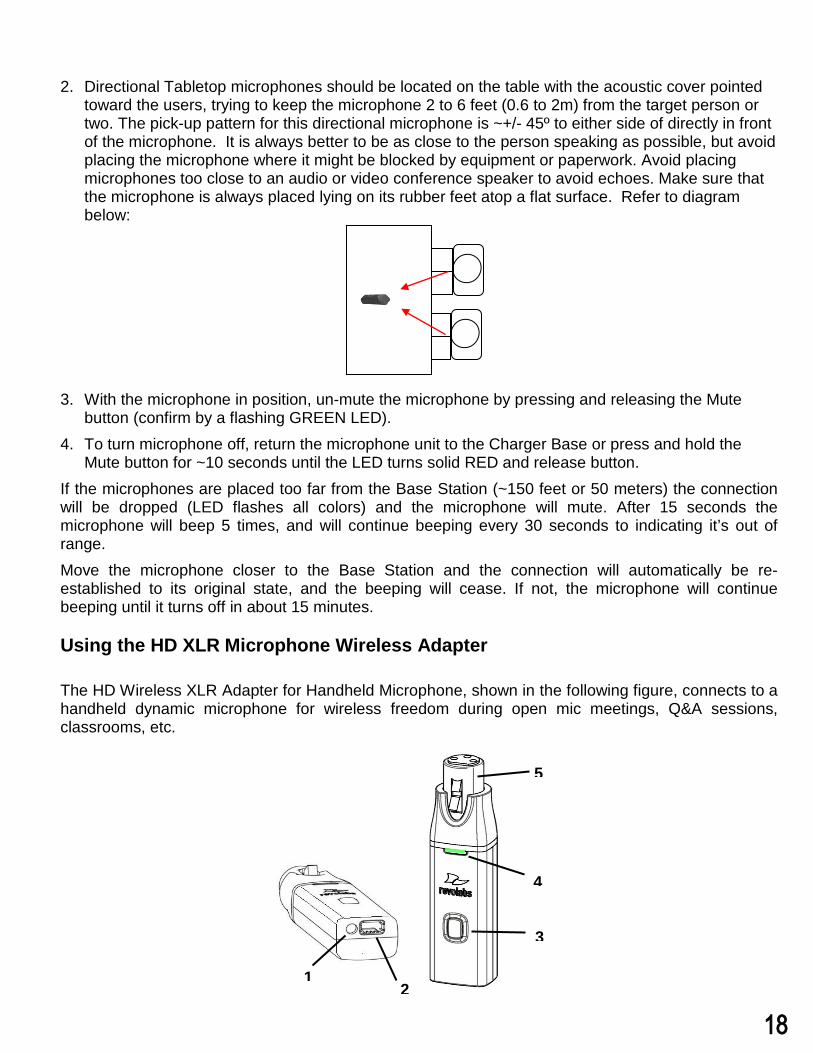
Using the HD Directional Tabletop Wireless Boundary Microphones The HD Tabletop Wireless Microphone, shown below, is designed to provide optimum coverage when placed on a conference room table in front of one or two people.
1. LED display — visual status for mute, un-mute, and pairing.2. Rubber feet — non-slip, vibration absorbing pads.3. Audio jack — accepts a 2.5mm plug.4. Charging port — docks to Revolabs HD Charger Bases.5. Mute button — press to mute, un-mute and pair microphone.6. Acoustic Cover — protects microphone element (non-removable).
To use the HD Directional Tabletop Microphone:
1. Remove the microphone from the Charger Base to turn on and automatically mute the mic.(indicated by a flashing RED LED)
1
23 4
5
645
45 Pickup patter
17
5
4
3
21
2. Directional Tabletop microphones should be located on the table with the acoustic cover pointedtoward the users, trying to keep the microphone 2 to 6 feet (0.6 to 2m) from the target person ortwo. The pick-up pattern for this directional microphone is ~+/- 45º to either side of directly in frontof the microphone. It is always better to be as close to the person speaking as possible, but avoidplacing the microphone where it might be blocked by equipment or paperwork. Avoid placingmicrophones too close to an audio or video conference speaker to avoid echoes. Make sure thatthe microphone is always placed lying on its rubber feet atop a flat surface. Refer to diagrambelow:
3. With the microphone in position, un-mute the microphone by pressing and releasing the Mutebutton (confirm by a flashing GREEN LED).
4. To turn microphone off, return the microphone unit to the Charger Base or press and hold theMute button for ~10 seconds until the LED turns solid RED and release button.
If the microphones are placed too far from the Base Station (~150 feet or 50 meters) the connection will be dropped (LED flashes all colors) and the microphone will mute. After 15 seconds the microphone will beep 5 times, and will continue beeping every 30 seconds to indicating it’s out of range. Move the microphone closer to the Base Station and the connection will automatically be re-established to its original state, and the beeping will cease. If not, the microphone will continue beeping until it turns off in about 15 minutes.
Using the HD XLR Microphone Wireless Adapter
The HD Wireless XLR Adapter for Handheld Microphone, shown in the following figure, connects to a handheld dynamic microphone for wireless freedom during open mic meetings, Q&A sessions, classrooms, etc.
18
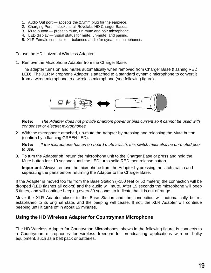
1. Audio Out port — accepts the 2.5mm plug for the earpiece.2. Charging Port — docks to all Revolabs HD Charger Bases.3. Mute button — press to mute, un-mute and pair microphone.4. LED display — visual status for mute, un-mute, and pairing.5. XLR Female connector — balanced audio for dynamic microphones.
To use the HD Universal Wireless Adapter:
1. Remove the Microphone Adapter from the Charger Base.The adapter turns on and mutes automatically when removed from Charger Base (flashing REDLED). The XLR Microphone Adapter is attached to a standard dynamic microphone to convert itfrom a wired microphone to a wireless microphone (see following figure).
Note: The Adapter does not provide phantom power or bias current so it cannot be used with condenser or electret microphones.
2. With the microphone attached, un-mute the Adapter by pressing and releasing the Mute button(confirm by a flashing GREEN LED).Note: If the microphone has an on-board mute switch, this switch must also be un-muted priorto use.
3. To turn the Adapter off, return the microphone unit to the Charger Base or press and hold theMute button for ~10 seconds until the LED turns solid RED then release button.Important: Always remove the microphone from the Adapter by pressing the latch switch andseparating the parts before returning the Adapter to the Charger Base.
If the Adapter is moved too far from the Base Station (~150 feet or 50 meters) the connection will be dropped (LED flashes all colors) and the audio will mute. After 15 seconds the microphone will beep 5 times, and will continue beeping every 30 seconds to indicate that it is out of range. Move the XLR Adapter closer to the Base Station and the connection will automatically be re-established to its original state, and the beeping will cease. If not, the XLR Adapter will continue beeping until it turns off in about 15 minutes.
Using the HD Wireless Adapter for Countryman Microphone
The HD Wireless Adapter for Countryman Microphones, shown in the following figure, is connects to a Countryman microphones for wireless freedom for broadcasting applications with no bulky equipment, such as a belt pack or batteries.
19
5
4
3
21
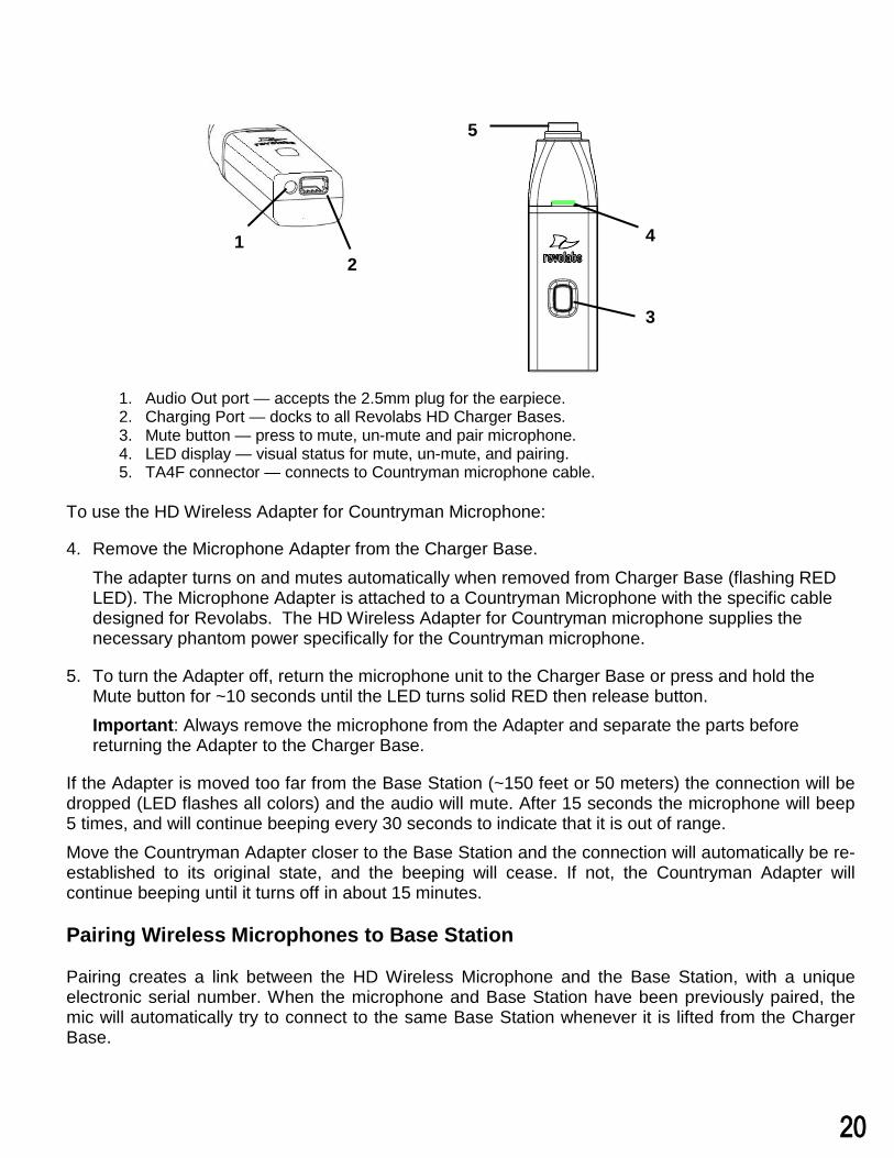
1. Audio Out port — accepts the 2.5mm plug for the earpiece.2. Charging Port — docks to all Revolabs HD Charger Bases.3. Mute button — press to mute, un-mute and pair microphone.4. LED display — visual status for mute, un-mute, and pairing.5. TA4F connector — connects to Countryman microphone cable.
To use the HD Wireless Adapter for Countryman Microphone:
4. Remove the Microphone Adapter from the Charger Base.The adapter turns on and mutes automatically when removed from Charger Base (flashing REDLED). The Microphone Adapter is attached to a Countryman Microphone with the specific cabledesigned for Revolabs. The HD Wireless Adapter for Countryman microphone supplies thenecessary phantom power specifically for the Countryman microphone.
5. To turn the Adapter off, return the microphone unit to the Charger Base or press and hold theMute button for ~10 seconds until the LED turns solid RED then release button.Important: Always remove the microphone from the Adapter and separate the parts beforereturning the Adapter to the Charger Base.
If the Adapter is moved too far from the Base Station (~150 feet or 50 meters) the connection will be dropped (LED flashes all colors) and the audio will mute. After 15 seconds the microphone will beep 5 times, and will continue beeping every 30 seconds to indicate that it is out of range. Move the Countryman Adapter closer to the Base Station and the connection will automatically be re-established to its original state, and the beeping will cease. If not, the Countryman Adapter will continue beeping until it turns off in about 15 minutes.
Pairing Wireless Microphones to Base Station
Pairing creates a link between the HD Wireless Microphone and the Base Station, with a unique electronic serial number. When the microphone and Base Station have been previously paired, the mic will automatically try to connect to the same Base Station whenever it is lifted from the Charger Base.
20
1
2 3
Note: Microphones in new systems must be paired to the Base Station with each microphone assigned to a unique channel on the Base Station.
Remember, microphones are always muted (flashing RED LED) when they are removed from the Charger Base and the Mute button needs to be pressed to make it “live” (flashing GREEN LED).
A microphone that is not paired will be indicated by a cycling RED-GREEN LED pattern. A Base Station channel that is not paired to a microphone will not show any activity on the channel LED (make sure unit is first powered on by observing GREEN backlit front panel display).
When channels are paired, both microphone and channel LEDs will flash RED as microphones are removed from the Charger Base and flash GREEN when un-muted. Remember that only one microphone can be paired to any single Base Station channel.
To pair an individual microphone to the Base Station:
1. Turn the microphone OFF (no LED activity). If the microphone is ON, press and hold the Mutebutton for 10 seconds until the LED turns solid RED then release the button to turn the unit off. (donot release the button when you hear two beeps).
2. Place the microphone unit into pairing mode by holding the Mute button down for seven seconds.The LED will turn solid RED. Release the Mute button. The microphone is now in pairing mode.
3. Within one minute, push and hold the button for the desired channel on the Base Station for sevenseconds until the LED turns solid red then release. The LED for that channel will be solid red untilpairing starts, as indicated by a quick GREEN flash, then switching to flashing RED on both themicrophone and the Base Station (muted audio). Pairing is now complete.
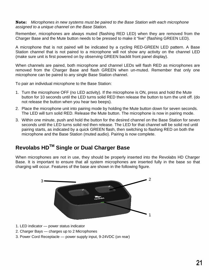
Revolabs HDTM Single or Dual Charger Base When microphones are not in use, they should be properly inserted into the Revolabs HD Charger Base. It is important to ensure that all system microphones are inserted fully in the base so that charging will occur. Features of the base are shown in the following figure.
1. LED indicator — power status indicator2. Charger Bays — charges up to 2 Microphones3. Power Cord Receptacle — power supply input, 9-24VDC (on rear)
21
Power Module The Charger Base requires 5VDC power, provided by the AC Adapter. Plug the supplied AC adapter into an appropriate power outlet 110-240 AC, 50-60Hz. The power LED on the Charger Base will illuminate.
Charging the Microphone Batteries
First-time use — Before using the wireless microphone the first time, charge the batteries in the microphones for eight hours (or overnight) in the Charger Base.
Recharging — When the YELLOW LED starts to flash intermittently on the microphone the battery has 30 minutes of charge remaining. Over time (years), batteries gradually wear down and will result in shorter run times. This is normal. Always return microphones to the Charger Base when not in use.
Important: The Lithium Polymer rechargeable batteries that power the microphones were released with both replaceable and non-replaceable type batteries. To distinguish between the 2 different type versions is by serial number only. Serial numbers are located on the label of the back of the microphone itself. Any serial number preference starting with either 7010 or 8020 are equipped with current replaceable rechargeable Lithium Polymer type batteries. If the serial number preference is anything else but 7010 or 8020 Please contact Yamaha Unified Communications, Inc. at www.uc.yamaha.com or your AV service provider for replacement instructions for returning and servicing non replaceable type microphone batteries. For replaceable type battery microphones, with serial number preference starting with either 7010 or 8020, replace only with the same manufacturer and model battery type recommended by Yamaha Unified Communications, Inc.. Please contact Yamaha Unified Communications, Inc. at www.uc.yamaha.com or your AV service provider for correct manufacturer approved and recommended replacement type batteries or process for return and replacement for either type battery.
Caution: Risk of explosion if batteries are mishandled or replaced by an incorrect type. Do not disassemble batteries or attempt to charge outside the system. Do not dispose of batteries in fire. Dispose of batteries in accordance with manufacturer’s instructions and local regulations.
Either a solid RED LED (charging) or solid GREEN LED (100% charged) will appear to confirm that the microphone is inserted properly in the Charger Base. The microphones are not transmitting audio to the HD Base Station while in the Charger Base. In normal use, batteries should fully charge in about 2 hours, but will “quick-charge” to 80% capacity in approximately 1 hour and 20 minutes. Fully charged microphones left in the Charger Base remain solid GREEN.
Updating the Revolabs HDTM Firmware
Revolabs HDTM Systems are field upgradable for the firmware portion of the Base Station and microphones. The firmware must be sent to the Base station using the Revolabs HD Panel. The software can be downloaded at https://uc.yamaha.com/resources/support.
22
Updating the HD Single/Dual Base Station and HD Microphones
1. Connect to the Base Station using the mini-USB cable.2. Pair both mics to the Base Station and make sure they are out of the Charger Base.3. Start the Revolabs HD Control Panel software4. Select the “Firmware” button on the Control Panel5. Choose the desired firmware version from the location it was saved during download.6. Choose whether you would like to update the Base Station, Mics, or Both.7. Select OK. The Revolabs HD Firmware Loader will notify you when complete.
The HD Microphone firmware updates wirelessly during the firmware process as long as the microphones are out of the Charger Base, paired to the Base Station, and communicating with the Base Station.
23
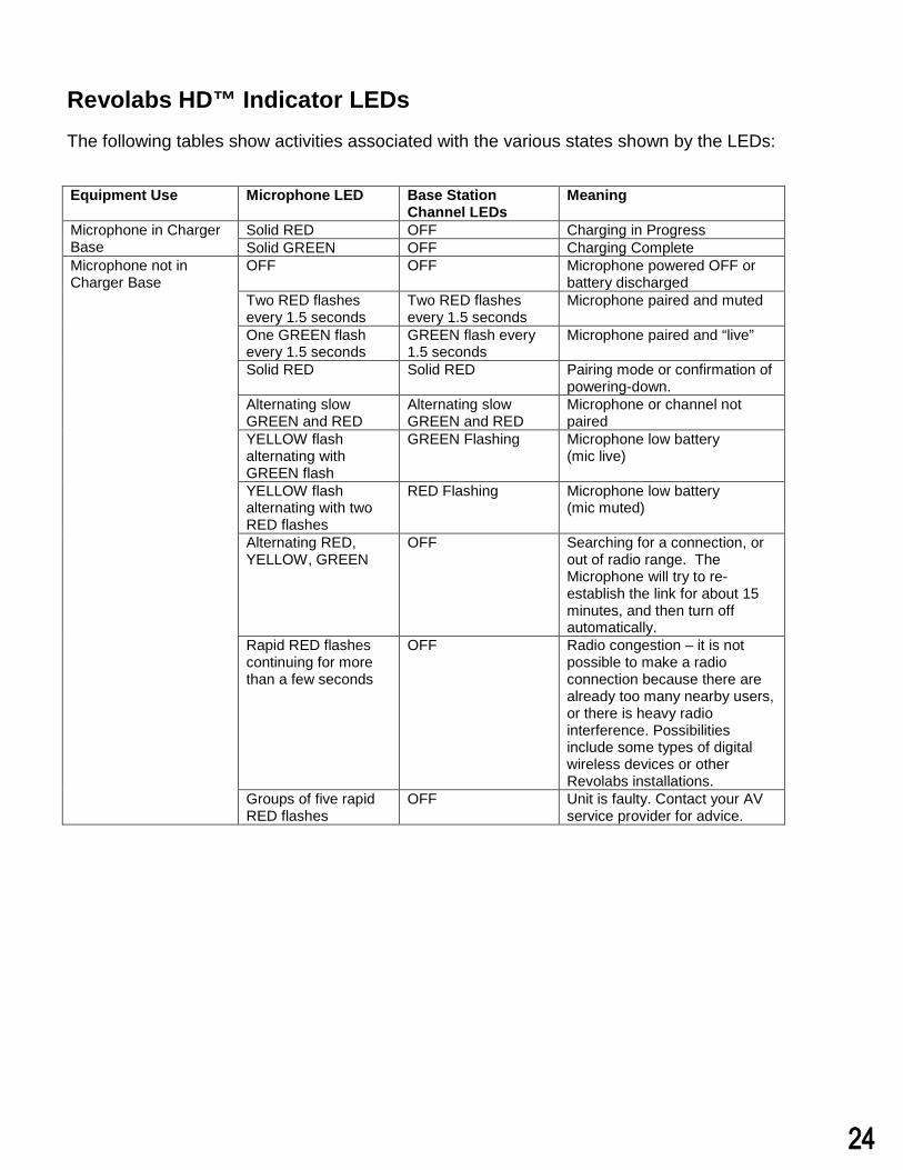
Revolabs HD™ Indicator LEDsThe following tables show activities associated with the various states shown by the LEDs:
Equipment Use Microphone LED Base Station Channel LEDs
Meaning
Microphone in Charger Base
Solid RED OFF Charging in Progress Solid GREEN OFF Charging Complete
Microphone not in Charger Base
OFF OFF Microphone powered OFF or battery discharged
Two RED flashes every 1.5 seconds
Two RED flashes every 1.5 seconds
Microphone paired and muted
One GREEN flash every 1.5 seconds
GREEN flash every 1.5 seconds
Microphone paired and “live”
Solid RED Solid RED Pairing mode or confirmation of powering-down.
Alternating slow GREEN and RED
Alternating slow GREEN and RED
Microphone or channel not paired
YELLOW flash alternating with GREEN flash
GREEN Flashing Microphone low battery (mic live)
YELLOW flash alternating with two RED flashes
RED Flashing Microphone low battery (mic muted)
Alternating RED, YELLOW, GREEN
OFF Searching for a connection, or out of radio range. The Microphone will try to re-establish the link for about 15 minutes, and then turn off automatically.
Rapid RED flashes continuing for more than a few seconds
OFF Radio congestion – it is not possible to make a radio connection because there are already too many nearby users, or there is heavy radio interference. Possibilities include some types of digital wireless devices or other Revolabs installations.
Groups of five rapid RED flashes
OFF Unit is faulty. Contact your AV service provider for advice.
24
Warranty Yamaha Unified Communications Inc. warrants this product to be free of manufacturing defects. Repair or replacement of any defective part or unit (at the discretion of the Seller) will be free of charge for the period defined in the Professional Products Limited Warranty.
Any attempt by the user to alter the equipment, or equipment damaged by negligence, accident, or Acts of God voids this warranty.
The Seller shall not be liable for any consequential damage resulting from the malfunction of this product. Should the user experience unsatisfactory performance from this equipment, contact the Seller to obtain instructions for return, or replacement, as deemed necessary.
This warranty is not transferable by the original end user. Complete details and terms of the Limited Warranty can be found at: www.uc.yamaha.com
Yamaha Unified Communications Inc.144 North Road Suite 3250
Sudbury, MA 01776 [email protected].
800.326.1088
25
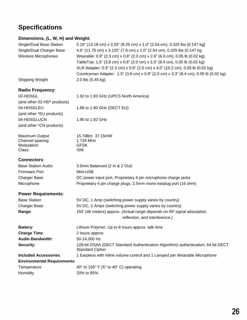
Specifications Dimensions, (L, W, H) and Weight: Single/Dual Base Station 5.19” (13.18 cm) x 3.25” (8.25 cm) x 1.0” (2.54 cm), 0.325 lbs (0.147 kg) Single/Dual Charger Base 4.6” (11.75 cm) x 3.125” (7.9 cm) x 1.0” (2.54 cm), 0.325 lbs (0.147 kg Wireless Microphones Wearable: 0.9” (2.3 cm) x 0.8” (2.0 cm) x 2.6” (6.6 cm), 0.05 lb (0.02 kg)
TableTop: 1.5” (3.8 cm) x 0.8” (2.0 cm) x 3.3” (8.4 cm), 0.05 lb (0.02 kg) XLR Adapter: 0.9” (2.3 cm) x 0.8” (2.0 cm) x 4.0” (10.2 cm), 0.05 lb (0.02 kg) Countryman Adapter: 1.5” (3.8 cm) x 0.8” (2.0 cm) x 3.3” (8.4 cm), 0.05 lb (0.02 kg)
Shipping Weight 2.0 lbs (5.45 kg)
Radio Frequency: 02-HDSGL 1.92 to 1.93 GHz (UPCS North America) (and other 02-HD* products) 04-HDSGLEU 1.88 to 1.90 GHz (DECT EU) (and other *EU products)04-HDSGLUCN 1.90 to 1.92 GHz (and other *CN products)
Maximum Output 15.7dBm 37.15mW Channel spacing: 1.728 MHz Modulation: GFSK Class: ISM
Connectors: Base Station Audio 3.5mm Balanced (2 In & 2 Out) Firmware Port Mini-USB Charger Base DC power input port, Proprietary 4 pin microphone charge jacks Microphone Proprietary 4 pin charge plugs, 2.5mm mono earplug port (16 ohm)
Power Requirements: Base Station 5V DC, 1 Amp (switching power supply varies by country) Charger Base 5V DC, 2 Amps (switching power supply varies by country) Range: 150’ (46 meters) approx. (Actual range depends on RF signal absorption,
reflection, and interference.)
Battery: Lithium Polymer, Up to 8 hours approx. talk time Charge Time: 2 hours approx. Audio Bandwidth: 50-14,000 HzSecurity: 128-bit DSAA (DECT Standard Authentication Algorithm) authentication, 64 bit DECT
Standard CipherIncluded Accessories: 1 Earpiece with inline volume control and 1 Lanyard per Wearable Microphone Environmental Requirements: Temperature 40° to 105° F (5° to 40° C) operating Humidity 20% to 85%
26
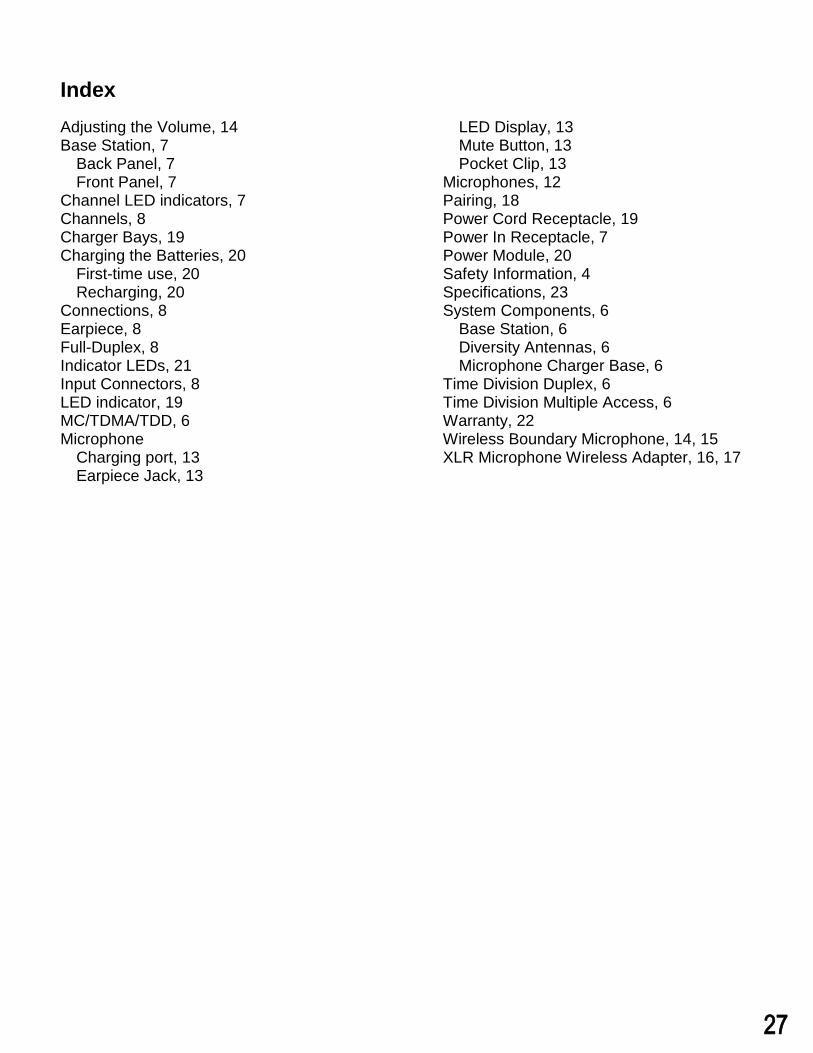
Index Adjusting the Volume, 14 Base Station, 7
Back Panel, 7 Front Panel, 7
Channel LED indicators, 7 Channels, 8 Charger Bays, 19 Charging the Batteries, 20
First-time use, 20 Recharging, 20
Connections, 8 Earpiece, 8 Full-Duplex, 8 Indicator LEDs, 21 Input Connectors, 8 LED indicator, 19 MC/TDMA/TDD, 6 Microphone
Charging port, 13 Earpiece Jack, 13
LED Display, 13 Mute Button, 13 Pocket Clip, 13
Microphones, 12 Pairing, 18 Power Cord Receptacle, 19 Power In Receptacle, 7 Power Module, 20 Safety Information, 4 Specifications, 23 System Components, 6
Base Station, 6 Diversity Antennas, 6 Microphone Charger Base, 6
Time Division Duplex, 6 Time Division Multiple Access, 6 Warranty, 22 Wireless Boundary Microphone, 14, 15 XLR Microphone Wireless Adapter, 16, 17
27
Note: Microphones must be fully charged for 8 hours and paired to the Base Station prior to first use.
Copyright 2018 Yamaha Unified Communications, Inc.MN-SINGLE-DUAL-USER-GUIDE-201805024-EN