Embed Size (px)
Citation preview
” LUCIAN BLAGA” UNIVERSITY of SIBIU
”HERMANN OBERTH” FACULTY OF ENGINEERING
DOCTORAL DISSERTATION
ABSTRACT
CONTRIBUŢII TEORETICE ŞI EXPERIMENTALE PRIVIND FILTRAREA GAZELOR NATURALE ÎN CÂMP ULTRASONIC
THEORETICAL AND EXPERIMENTAL CONTRIBUTIONS CONCERNING THE FILTERING OF NATURAL GASES IN ULTRASOUND FIELD
Scientific advisor: Prof. Eng. OPREAN CONSTANTIN, Ph.D.
Ph.D. graduate: Eng.Turc Dumitru
SIBIU 2013
2
Table of contents
INTRODUCTION 6 CHAPTER 1
NATURAL GASES AND THEIR QUALITY. THE NECESSITY OF USING AND PURIFYING THEM 9
1.1. GENERALITIES 1.2. NATURAL GASES AND THEIR QUALITIES 1.3. CONCLUSIONS
9 9
13
CHAPTER 2 CURRENT STATE OF RESEARCHES REGARDING THE FILTERING OF NATURAL GASES
2.1. GENERALITIES 2.2. SOLID IMPURITIES AND THEIR RETENTION 2.3. SEPARATION OF IMPURITIES
2.3.1. Separating solid and liquid impurities from gases. Separation installations 2.3.1.1. Functioning principle of the separators presently used in the methane gas industry 2.3.1.2. Hydraulic separators 2.3.1.3. Separating the liquid and the solid particles from gases in the collecting and transport pipes 2.3.1.4. Separating the liquid and the solid particles from gases under the action of the centrifugal force. The separator with cyclone 2.3.1.5. The liquid and the solid particles from gases under the combined action of the centrifugal and gravitational forces. The horizontal separator with coil pipe 2.3.1.6. The horizontal buried separator (the underground liquid accumulator) 2.3.1.7. The horizontal separator with fog screen 2.3.1.8. The vertical separator with fog screen out of ceramic rings
§ 2.3.2. Some considerations regarding removing dust by filtering 2.3.2.1. Decanting 2.3.2.2. Separating by abruptly reducing speed 2.3.2.3. Eliminating dust by washing 2.3.2.4. Filtering in porous layer (total) 2.3.2.5. Electro-static filters 2.3.2.6. Separating particles by coalescence
2.4. COMPARISON BETWEEN THE FILETRING SYSTEMS (DEDUSTING) 2.5. EXPLOITING THE FILTERING LINES
2.5.1. Generalities 2.5.2. Exploiting under emergency operation of a filtering line 2.5.3. Case study-exploiting under emergency operation of the cone-shaped filters
2.6. MAINTENANCE OF FILTERS WITHIN S.R.M. 2.7. CHECKING THE FILTERS – CHECKING CRITERIA 2.8. CASE STUDY – MAINTENANCE OF THE CONE-SHAPED FILTERS 2.9. CONCLUSIONS
14 14 16 29 29
30 34
36
37
39 40 41 41 41 42 42 44 45 49 51 52 53 53 54 54 56 57 58 59
CHAPTER 3
THEORETICAL AND EXPERIMENTAL CONTRIBUTIONS REGARDING IMPROVING THE FILTERING OF NATURAL GASES USING THE ULTRASONIC FIELD
3.1. GENERAL CONSIDERATIONS REGARDING CLASSICAL FILTERING 3.2. THEORETICAL AND EXPERIMENTAL CONTRIBUTIONS REGARDING THE DESIGN REQUIREMENTS OF A FILTERING INSTALLATION
3.2.1. Contributions regarding the types of the most used natural gases filters 3.2.2. Calculation of the pressure drop on filters
61 61
62 63 64
3
CHAPTER I
NATURAL GASES AND THEIR QUALITY. THE NECESSITY OF USING AND
PURIFYING THEM
The national system of natural gases transmission is presently made out of 13110 km of transmission
mains and supply pipe connections, being foreseen with 21 command stations of the valves and/or
technological nodes, 961 tuning-measuring and/or measuring of the processed gases from national
exploitations stations, 3 stations for measuring gases taken from import, 6 measuring stations placed on
the transit pipes, 6 stations for compressing gases, 857 stations for cathode protection of the pipes, 575
installations for gases odorization and millions of users.
For the good functioning of the entire SNTGN (National System Of Natural Gases
Transmission), avoiding accidents in order to reduce the technical risk attached to the transmission and
distribution of natural gases, for an efficient usage and processing, first, the natural gases need to be
filtered and then purified or a logical combination of these operations required by the technological
process.
Filtering is the operation by which the solid matter transmitted by the natural gases flow from
the extraction point to the usage point is retained. The solid matters existing in the natural gas flow
neither have the same shape or size nor the same chemical composition. The smallest suspended
particles have a size of approximately 0,002 µm (meaning 2 nm) and the largest ones can measure
millimeters or even tens of millimeters. Although only very few of the solid particles have a sphere-
like-shape, further down in all demonstrations presented, they will be considered as sphere-shaped,
their diameter being the main feature.
From this qualitative point of view, the individual particles are classified according to their
diameter in gross (if their diameter is bigger than 2.5 µm) and fine (if their diameter is smaller than 2.5
µm). The fine particles represent a rather complicated technical problem regarding their retention
because they remain suspended in the gas for an almost undetermined period.
Very small particles gather to form bigger particles, usually also from the category of those of
fine size and they represent the same problem difficult to solve in certain situations
Sometimes, these fine particles can also be dangerous because they can contain toxic
compounds, such as heavy metals (mercury) or their compounds with certain persistent organic
pollutants (polynuclear aromatics), according to the granulation of the particles. This is due to the fact
4
that many toxic compounds found as vapors in the natural gases condensate on the already present fine
dust particles
That is why, in order to retain solid impurities from the natural gases, one uses dust separator
filters which, based on their functioning principle can be:
ü gravimetric separators;
ü centrifugal separators;
ü separators by abruptly reducing speed;
ü separators by cleaning;
ü filters;
ü separators in electric field;
ü separators by coalescence;
ü special separators.
Along the solid particles of different shapes and sizes, natural gases also contain a series of
gases such as hydrogen sulphide, ammoniac, carbon dioxide, sulphur alcohols, sulphur dioxide and
others which, in order to prevent polluting the atmosphere, out of the necessity of accomplishing
advanced purities for some reactant substances and for recovering some valuable compounds, require
an appropriate purification.
The usual purification procedures of natural gases can be based on the following processes or
unitary operations:
ü absorption in a liquid called absorbent;
ü absorption on a solid material called absorbent;
ü fractionation;
ü crystallization and filtering;
ü chemical conversion of impurities;
ü special procedures.
As a consequence, for an efficient usage, a risk free exploitation and a high maintenance of the
entire system of natural gases transmission and distribution, the purification and filtering of the gases at
the quality requested by the end consumer is necessary
5
CHAPTER II
FLOW STATE OF RESEARCHES REGARDING THE FILTERING OF NATURAL
GASES
Solid impurities and their retention
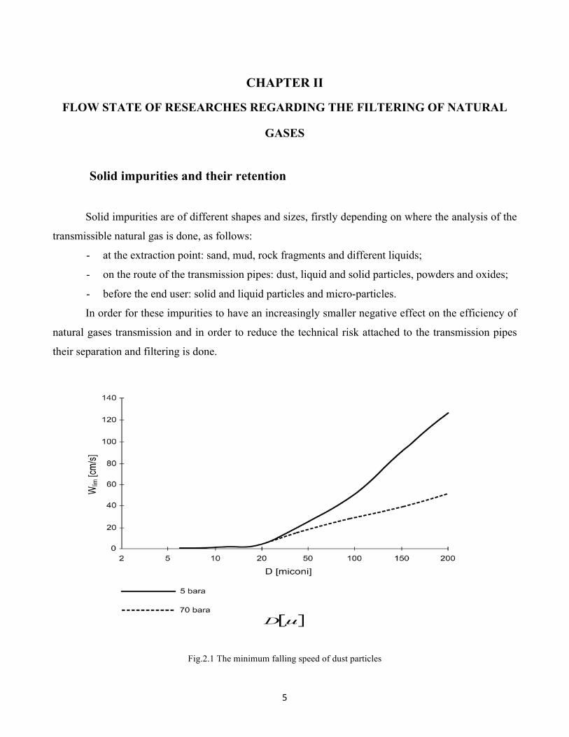
Solid impurities are of different shapes and sizes, firstly depending on where the analysis of the
transmissible natural gas is done, as follows:
- at the extraction point: sand, mud, rock fragments and different liquids;
- on the route of the transmission pipes: dust, liquid and solid particles, powders and oxides;
- before the end user: solid and liquid particles and micro-particles.
In order for these impurities to have an increasingly smaller negative effect on the efficiency of
natural gases transmission and in order to reduce the technical risk attached to the transmission pipes
their separation and filtering is done.
Fig.2.1 The minimum falling speed of dust particles
6
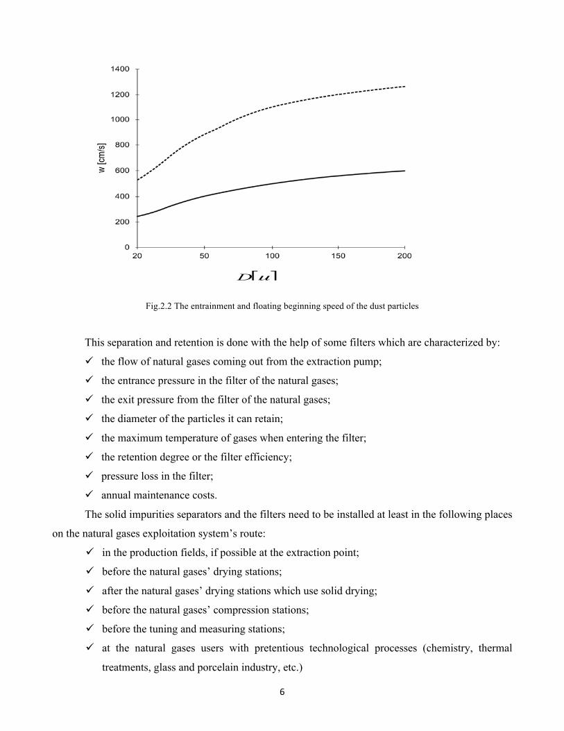
Fig.2.2 The entrainment and floating beginning speed of the dust particles
This separation and retention is done with the help of some filters which are characterized by:
ü the flow of natural gases coming out from the extraction pump;
ü the entrance pressure in the filter of the natural gases;
ü the exit pressure from the filter of the natural gases;
ü the diameter of the particles it can retain;
ü the maximum temperature of gases when entering the filter;
ü the retention degree or the filter efficiency;
ü pressure loss in the filter;
ü annual maintenance costs.
The solid impurities separators and the filters need to be installed at least in the following places
on the natural gases exploitation system’s route:
ü in the production fields, if possible at the extraction point;
ü before the natural gases’ drying stations;
ü after the natural gases’ drying stations which use solid drying;
ü before the natural gases’ compression stations;
ü before the tuning and measuring stations;
ü at the natural gases users with pretentious technological processes (chemistry, thermal
treatments, glass and porcelain industry, etc.)
7
The filtering operation consists in passing a fluid through a permeable medium (filter) in order
to retain the impurities. As filtering material one can use for example, a textile material with fibers
regularly (fabrics) or irregularly placed (fibers or felt), or a grained material in which the grains can be
free and constitute the filter’s stuffing.
The filtering mechanism in a filtering material is complex because inertia effects, adherence
effects, diffusion effects, effects of an electrostatic nature and the griddle effect appear.
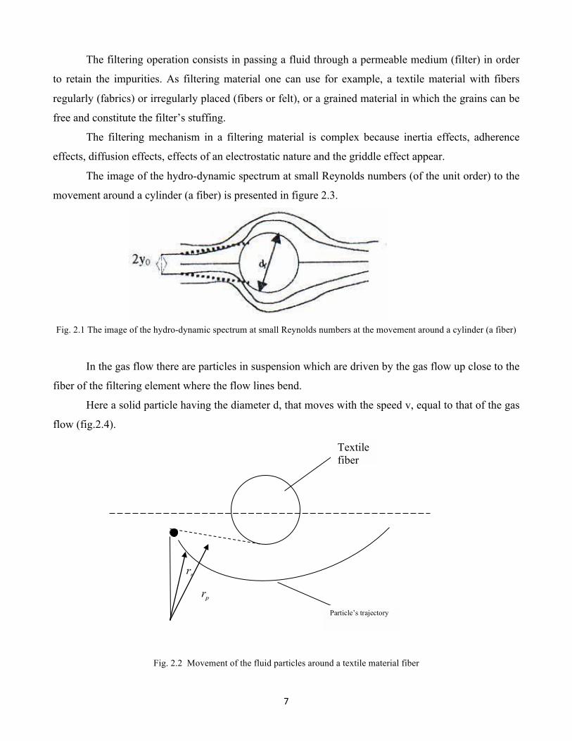
The image of the hydro-dynamic spectrum at small Reynolds numbers (of the unit order) to the
movement around a cylinder (a fiber) is presented in figure 2.3.
Fig. 2.1 The image of the hydro-dynamic spectrum at small Reynolds numbers at the movement around a cylinder (a fiber)
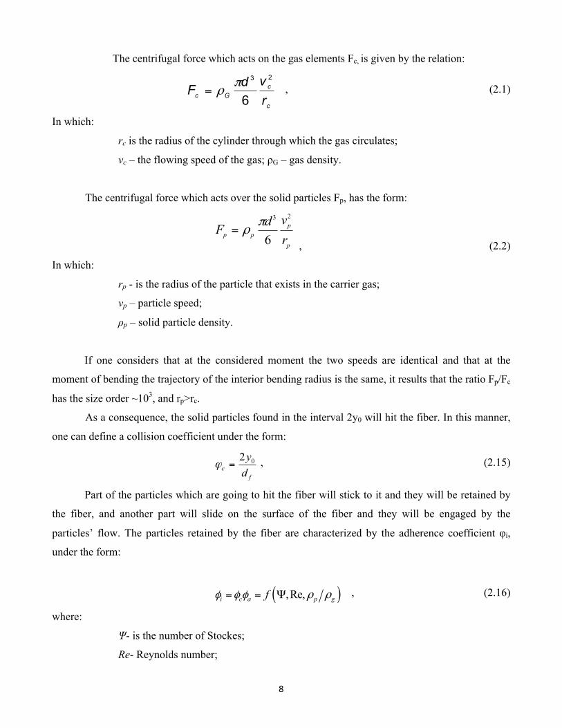
In the gas flow there are particles in suspension which are driven by the gas flow up close to the
fiber of the filtering element where the flow lines bend.
Here a solid particle having the diameter d, that moves with the speed v, equal to that of the gas
flow (fig.2.4).
Fig. 2.2 Movement of the fluid particles around a textile material fiber
Textile fiber
Particle’s trajectory
8
The centrifugal force which acts on the gas elements Fc, is given by the relation:
c
cGc r
vdF23
6π
ρ= , (2.1)
In which:
rc is the radius of the cylinder through which the gas circulates;
vc – the flowing speed of the gas; ρG – gas density.
The centrifugal force which acts over the solid particles Fp, has the form:
p
ppp r
vdF23
6π
ρ= , (2.2)
In which:
rp - is the radius of the particle that exists in the carrier gas;
vp – particle speed;
ρp – solid particle density.
If one considers that at the considered moment the two speeds are identical and that at the
moment of bending the trajectory of the interior bending radius is the same, it results that the ratio Fp/Fc
has the size order ~103, and rp>rc.
As a consequence, the solid particles found in the interval 2y0 will hit the fiber. In this manner,
one can define a collision coefficient under the form:
fc d
y02=ϕ , (2.15)
Part of the particles which are going to hit the fiber will stick to it and they will be retained by
the fiber, and another part will slide on the surface of the fiber and they will be engaged by the
particles’ flow. The particles retained by the fiber are characterized by the adherence coefficient φi,
under the form:
( ),Re,i c a p gfφ φ φ ρ ρ= = Ψ , (2.16)
where:
Ψ- is the number of Stockes;
Re- Reynolds number;
9
ρp/ρg- ratio of relative densities solid/gas particles.
The number of Stockes ψ has the formula:
dfcdv upp
η
ρψ
18
2
= , (2.17)
In which:
Cu –is the number of Cunningham, which takes into consideration the effect of the
Brownian movement;
Λ- the length which a molecule freely passes and the resulted formula is:
11 2uc d
=+ Λ
, (2.18)
The number of Stockes results from the ratio of the inertia forces:
( )( );
184
22183
16 22323
dfvd
dfvdvd
Rvrvd
FF pp
p
pp
p
ppp
visc
in
η
ρ
η
ρ
πη
πρ===
(rp=df/2) , (2.19)
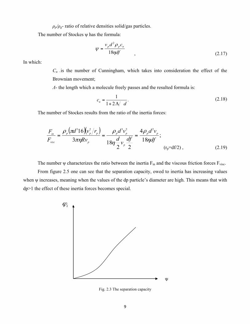
The number ψ characterizes the ratio between the inertia Fin and the viscous friction forces Fvisc.
From figure 2.5 one can see that the separation capacity, owed to inertia has increasing values
when ψ increases, meaning when the values of the dp particle’s diameter are high. This means that with
dp>1 the effect of these inertia forces becomes special.
Fig. 2.3 The separation capacity
10
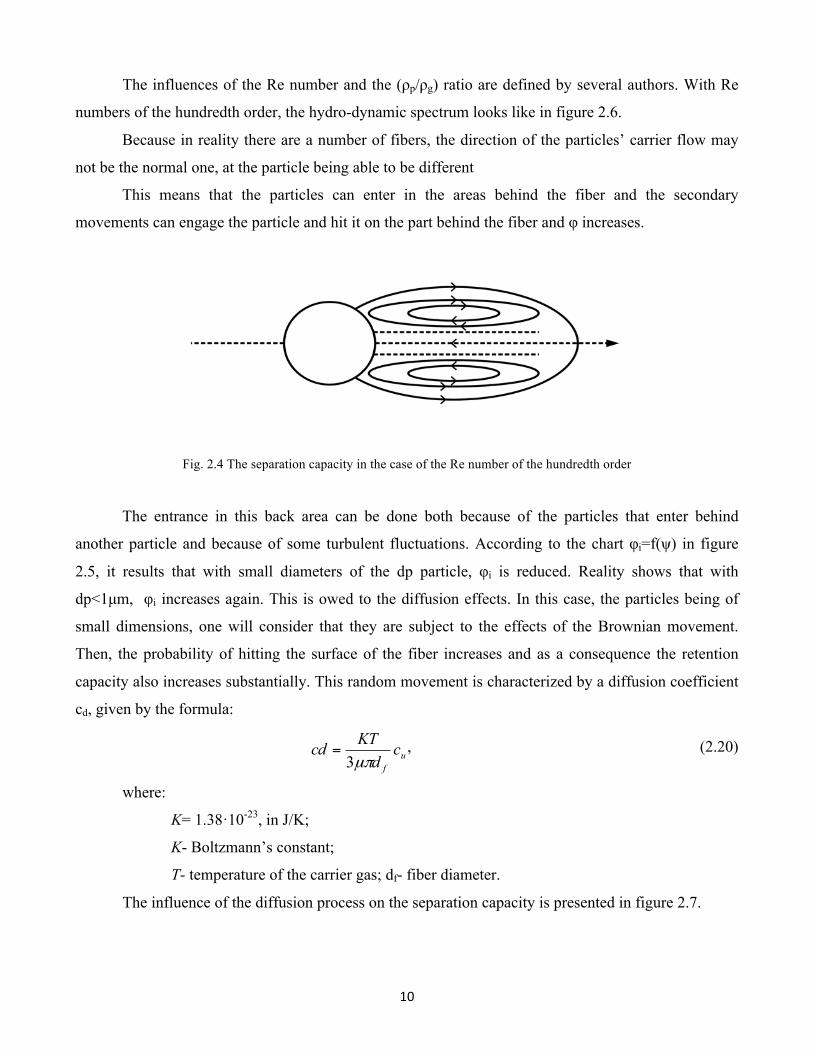
The influences of the Re number and the (ρp/ρg) ratio are defined by several authors. With Re
numbers of the hundredth order, the hydro-dynamic spectrum looks like in figure 2.6.
Because in reality there are a number of fibers, the direction of the particles’ carrier flow may
not be the normal one, at the particle being able to be different
This means that the particles can enter in the areas behind the fiber and the secondary
movements can engage the particle and hit it on the part behind the fiber and φ increases.
Fig. 2.4 The separation capacity in the case of the Re number of the hundredth order
The entrance in this back area can be done both because of the particles that enter behind
another particle and because of some turbulent fluctuations. According to the chart φi=f(ψ) in figure
2.5, it results that with small diameters of the dp particle, φi is reduced. Reality shows that with
dp<1µm, φi increases again. This is owed to the diffusion effects. In this case, the particles being of
small dimensions, one will consider that they are subject to the effects of the Brownian movement.
Then, the probability of hitting the surface of the fiber increases and as a consequence the retention
capacity also increases substantially. This random movement is characterized by a diffusion coefficient
cd, given by the formula:
u
f
cd
KTcdµπ3
= , (2.20)
where:
K= 1.38·10-23, in J/K;
K- Boltzmann’s constant;
T- temperature of the carrier gas; df- fiber diameter.
The influence of the diffusion process on the separation capacity is presented in figure 2.7.

11
The separation ratio increases substantially through the effect of diffusion with small Pc
numbers, meaning small flow values, small values of df and high diffusion coefficients, meaning small
dps. Pc is Peclet’s criteria and has the form:
Ddv
P fc
⋅= , (2.21)
On the particles which pass through the filter the electrostatic forces are present. This
phenomenon is owed to the electrostatic charge of the particle and fiber due to the friction with the gas.
The electrostatic charge effect is present at a flowing speed of v = 1.5…2 m/s. Their effect is as
high as the particles’ dimensions are small. A determinant role in the functioning of the filters is the
adherence of the fiber particles. In order to sometimes increase this retention capacity, one can
additionally increase the adherence coefficient, either by moistening the fiber or by setting a layer of
oil.
For the particles, if the condition s>3d is met, this effect does not occur. If the surfaces are
active, these bridges can also appear in the case of s>3d but they are unstable, and the griddle effect is
intermittent. This griddle effect can occur only on the exterior surfaces of the filters. Thus, a layer
forms on the filter’s surface which in return retains the particles with bigger diameters of solid
impurities.
The thickness of this layer is fluctuant, in time leading to the increase of the pressure drop on
the filtering element, given by the formula:
( ) hStSvC pi ⋅⋅⋅−=⋅⋅⋅ ρε1 , (2.22) Particule de praf - Dust particles
Fig. 2.5 The influence of the diffusion process on the
seperation capacity
12
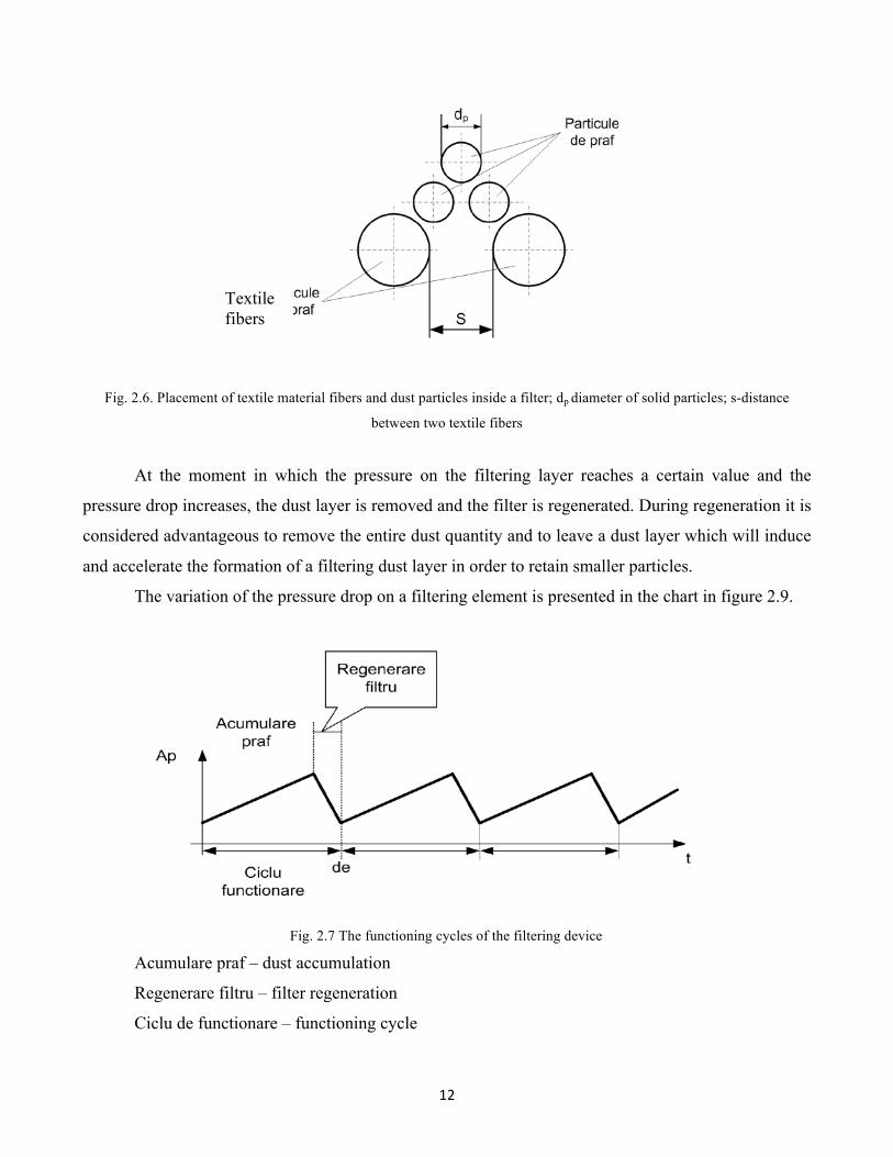
Fig. 2.6. Placement of textile material fibers and dust particles inside a filter; dp diameter of solid particles; s-distance
between two textile fibers
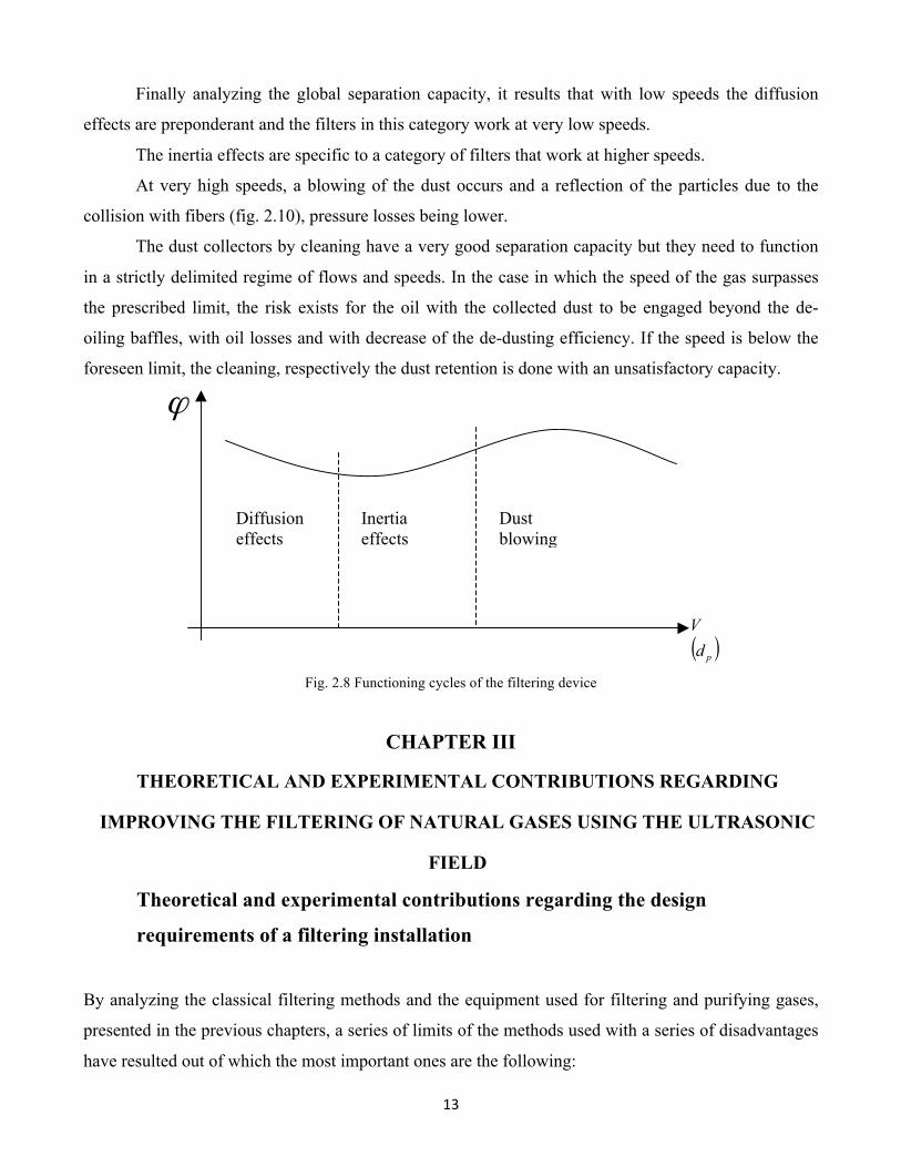
At the moment in which the pressure on the filtering layer reaches a certain value and the
pressure drop increases, the dust layer is removed and the filter is regenerated. During regeneration it is
considered advantageous to remove the entire dust quantity and to leave a dust layer which will induce
and accelerate the formation of a filtering dust layer in order to retain smaller particles.
The variation of the pressure drop on a filtering element is presented in the chart in figure 2.9.
Fig. 2.7 The functioning cycles of the filtering device
Acumulare praf – dust accumulation
Regenerare filtru – filter regeneration
Ciclu de functionare – functioning cycle
Textile fibers
13
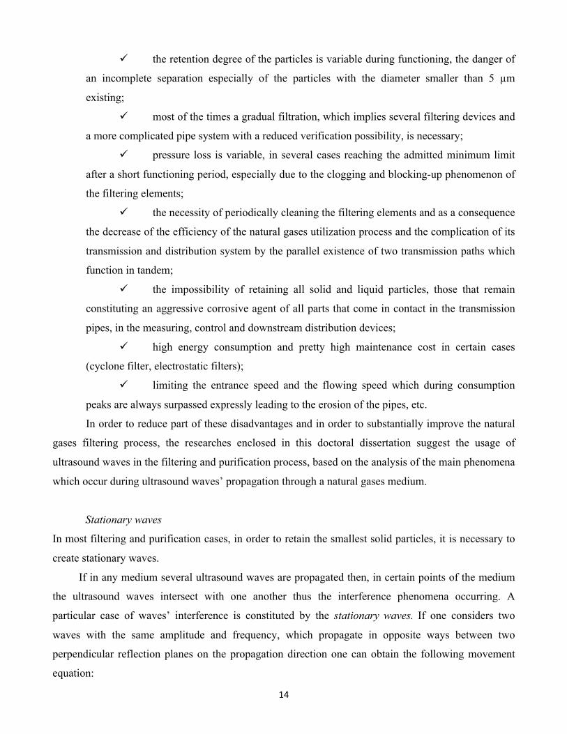
Finally analyzing the global separation capacity, it results that with low speeds the diffusion
effects are preponderant and the filters in this category work at very low speeds.
The inertia effects are specific to a category of filters that work at higher speeds.
At very high speeds, a blowing of the dust occurs and a reflection of the particles due to the
collision with fibers (fig. 2.10), pressure losses being lower.
The dust collectors by cleaning have a very good separation capacity but they need to function
in a strictly delimited regime of flows and speeds. In the case in which the speed of the gas surpasses
the prescribed limit, the risk exists for the oil with the collected dust to be engaged beyond the de-
oiling baffles, with oil losses and with decrease of the de-dusting efficiency. If the speed is below the
foreseen limit, the cleaning, respectively the dust retention is done with an unsatisfactory capacity.
Fig. 2.8 Functioning cycles of the filtering device
CHAPTER III
THEORETICAL AND EXPERIMENTAL CONTRIBUTIONS REGARDING
IMPROVING THE FILTERING OF NATURAL GASES USING THE ULTRASONIC
FIELD Theoretical and experimental contributions regarding the design
requirements of a filtering installation
By analyzing the classical filtering methods and the equipment used for filtering and purifying gases,
presented in the previous chapters, a series of limits of the methods used with a series of disadvantages
have resulted out of which the most important ones are the following:
Diffusion effects
Inertia effects
Dust blowing
ϕ
( )pdV
14
ü the retention degree of the particles is variable during functioning, the danger of
an incomplete separation especially of the particles with the diameter smaller than 5 µm
existing;
ü most of the times a gradual filtration, which implies several filtering devices and
a more complicated pipe system with a reduced verification possibility, is necessary;
ü pressure loss is variable, in several cases reaching the admitted minimum limit
after a short functioning period, especially due to the clogging and blocking-up phenomenon of
the filtering elements;
ü the necessity of periodically cleaning the filtering elements and as a consequence
the decrease of the efficiency of the natural gases utilization process and the complication of its
transmission and distribution system by the parallel existence of two transmission paths which
function in tandem;
ü the impossibility of retaining all solid and liquid particles, those that remain
constituting an aggressive corrosive agent of all parts that come in contact in the transmission
pipes, in the measuring, control and downstream distribution devices;
ü high energy consumption and pretty high maintenance cost in certain cases
(cyclone filter, electrostatic filters);
ü limiting the entrance speed and the flowing speed which during consumption
peaks are always surpassed expressly leading to the erosion of the pipes, etc.
In order to reduce part of these disadvantages and in order to substantially improve the natural
gases filtering process, the researches enclosed in this doctoral dissertation suggest the usage of
ultrasound waves in the filtering and purification process, based on the analysis of the main phenomena
which occur during ultrasound waves’ propagation through a natural gases medium.
Stationary waves
In most filtering and purification cases, in order to retain the smallest solid particles, it is necessary to
create stationary waves.
If in any medium several ultrasound waves are propagated then, in certain points of the medium
the ultrasound waves intersect with one another thus the interference phenomena occurring. A
particular case of waves’ interference is constituted by the stationary waves. If one considers two
waves with the same amplitude and frequency, which propagate in opposite ways between two
perpendicular reflection planes on the propagation direction one can obtain the following movement
equation:
15
( ) ( )21 sinsin krtAkrtAy ++−= ωω , (3.91)
In which r1 and r2 are the distances from point M, to the vibration.
If one considers the separation surfaces of the perfectly reflecting mediums, the entire energy
from the direct wave is found in the reflected wave, one can deduce the pressure equation p, in a point
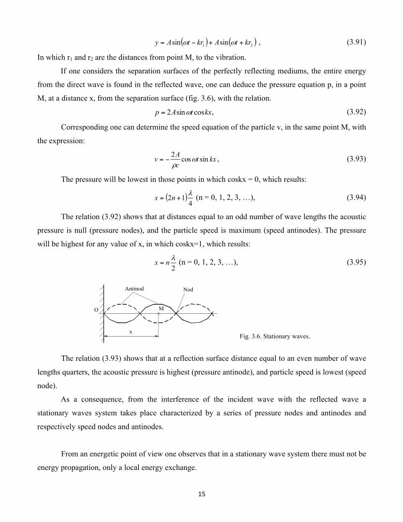
M, at a distance x, from the separation surface (fig. 3.6), with the relation.
kxtAp cossin2 ω= , (3.92)
Corresponding one can determine the speed equation of the particle v, in the same point M, with
the expression:
kxtcAv sincos2
ωρ
−= , (3.93)
The pressure will be lowest in those points in which coskx = 0, which results:
( )4
12 λ+= nx (n = 0, 1, 2, 3, …), (3.94)
The relation (3.92) shows that at distances equal to an odd number of wave lengths the acoustic
pressure is null (pressure nodes), and the particle speed is maximum (speed antinodes). The pressure
will be highest for any value of x, in which coskx=1, which results:
2λnx = (n = 0, 1, 2, 3, …), (3.95)
Fig. 3.6. Stationary waves.
The relation (3.93) shows that at a reflection surface distance equal to an even number of wave
lengths quarters, the acoustic pressure is highest (pressure antinode), and particle speed is lowest (speed
node).
As a consequence, from the interference of the incident wave with the reflected wave a
stationary waves system takes place characterized by a series of pressure nodes and antinodes and
respectively speed nodes and antinodes.
From an energetic point of view one observes that in a stationary wave system there must not be
energy propagation, only a local energy exchange.
Antinod Nod
M
x
O
16
In the filtering and purification with ultrasounds technologies stationary waves are used because
they lead to the coalescence phenomena which consists in grouping the fine particles (with dimensions
smaller than 0.1 µm) in particles with smaller dimensions (even bigger than 10 µm) easy to separate by
any filter. These big particles are formed in the pressure antinodes created by the stationary waves then
being taken by the gases that circulate with a corresponding flowing speed and retained by the filtering
element.
Diffraction and diffusion of ultra-acoustic waves
Ultra-acoustic waves have the property of going around obstacles they encounter on their way if the
obstacles have dimensions of the same size or smaller than the wave length. Thus, the diffraction
phenomenon occurs, the vibratory energy reaching points in the medium that are found behind the
obstacle. As a consequence, diffraction is the phenomena of the propagation direction change of the
ultra-acoustic wave as a consequence of its passing around an obstacle. In this case, the problem at
hand is the distribution of the ultra-acoustic energy behind the obstacle (impurities).
Just as the interference phenomena, the diffraction phenomena can be explained through the
wavelike nature of the ultrasonic waves.
According to Huygens’ Principle, with any progressive wave, each point can be considered as a
center of elementary waves, in any point of the vibratory field the vibration state resulting from the
interference of these elementary waves.
Experimentally it has been noted that the manner in which the ultrasonic waves’ field is
deformed by introducing an obstacle largely depends on the ratio between the size of the obstacle and
the wave length of the ultrasonic waves. In the case in which the wave length is neglectable in relation
to the solid impurity’s dimensions, the ultrasonic energy propagates rectilinear following the laws of
reflection and refraction. In the case in which the wave length is high in relation to the impurity’s
dimension, the ultrasonic energy goes around the obstacle so that practically no shadow occurs starting
from a certain distance behind the obstacle.
Aside from diffraction, the acoustic waves are distributed when encountering an obstacle, part
of them interfering with the incident waves. In the case of some simple and regulated form types of
obstacles (sphere, cylinder, disc) one can evaluate the diffraction and diffusion.
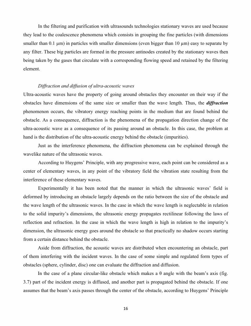
In the case of a plane circular-like obstacle which makes a θ angle with the beam’s axis (fig.
3.7) part of the incident energy is diffused, and another part is propagated behind the obstacle. If one
assumes that the beam’s axis passes through the center of the obstacle, according to Huygens’ Principle
17
it becomes a new oscillation center, a new sphere-like wave being born. The speed of particle u, is
under the form of:
tUu ωsin= , (3.96)
Fig. 3.7. Angular allocation of the
particle’s speeds at the diagonal
incidence of an ultrasound beam
on a circular obstacle
Unda incidenta – incident wave
Unde reflectata – reflected wave
and the corresponding acoustic pressure p, has the form:
tvUp ωρ sin= , (3.97)
In which: v is the oscillation velocity speed’s module.
In a point M, on the circular obstacle found at distance r, from the center, the vibration speed of
the particle ur, is:
⎟⎠
⎞⎜⎝
⎛−=vrtuu or ωθ sincos , (3.98)
And the corresponding pressure pr, is:
⎟⎠
⎞⎜⎝
⎛−
+
=vrt
rr
upr ωω
θρω sin1cos
2
2
2
, (3.99)
Since the incident wave and the reflected wave interfere in point M, a resulting pressure po, will
exist under the form:
ro ppp += , (3.100)
Replacing (3.97) and (3.98) in (3.99) after processing the expression following results:
Unda incidenta
,
Unda reflectata
,O
U
UUo
rM
O
Sphere-like
18
tsinr21
vrtsincosr2
1tsin
r1v
rtsincos1
pp
2
2
2
2
o
ωλ
π
ωθλ
π
ωϑω
ϑθω
⎟⎠
⎞⎜⎝
⎛+
⎟⎠
⎞⎜⎝
⎛ −+=
+
⎟⎠
⎞⎜⎝
⎛ −+= (3.101)
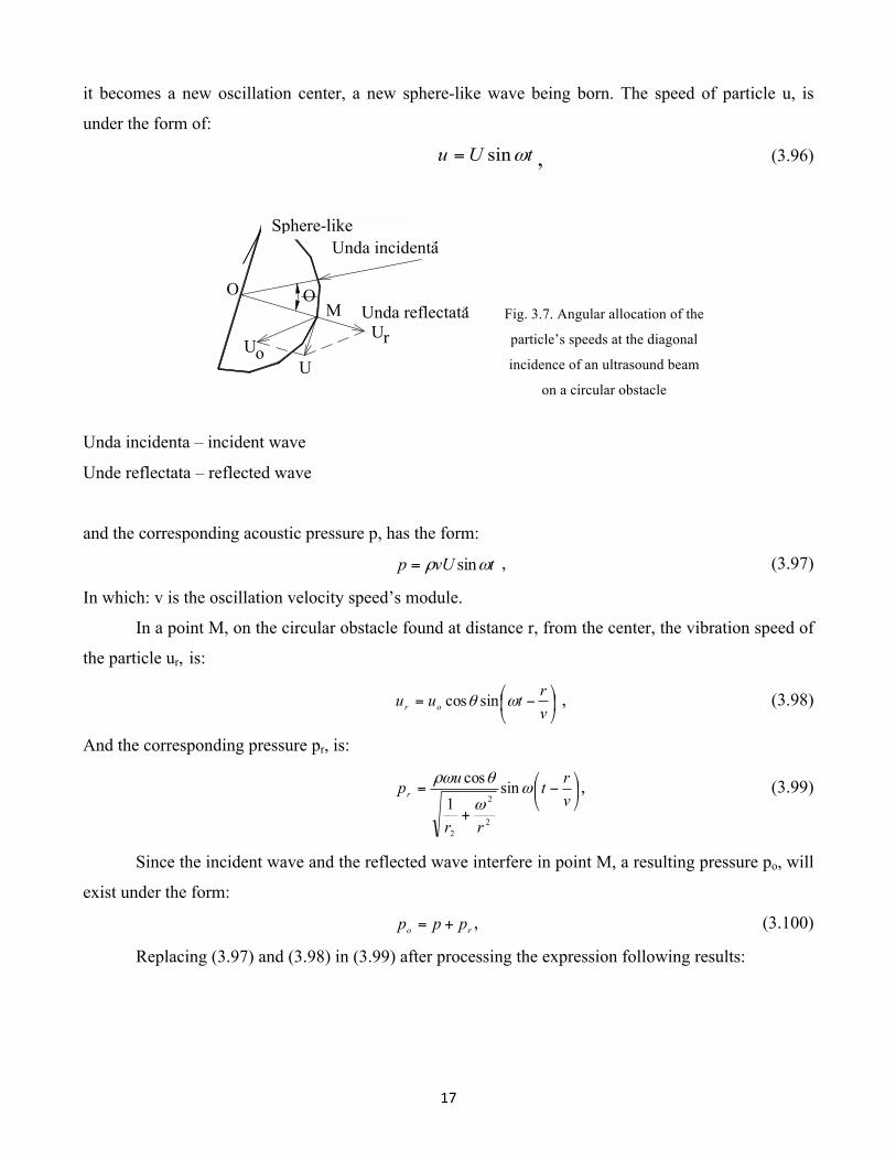
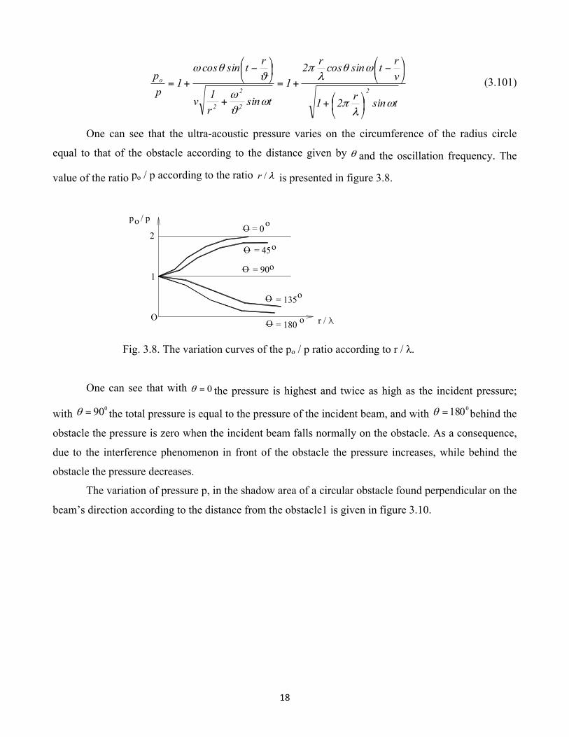
One can see that the ultra-acoustic pressure varies on the circumference of the radius circle
equal to that of the obstacle according to the distance given by θ and the oscillation frequency. The
value of the ratio po / p according to the ratio λ/r is presented in figure 3.8.
Fig. 3.8. The variation curves of the po / p ratio according to r / λ.
One can see that with 0=θ the pressure is highest and twice as high as the incident pressure;
with 090=θ the total pressure is equal to the pressure of the incident beam, and with 0180=θ behind the
obstacle the pressure is zero when the incident beam falls normally on the obstacle. As a consequence,
due to the interference phenomenon in front of the obstacle the pressure increases, while behind the
obstacle the pressure decreases.
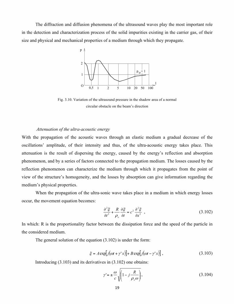
The variation of pressure p, in the shadow area of a circular obstacle found perpendicular on the
beam’s direction according to the distance from the obstacle1 is given in figure 3.10.
O
O
O
O
= 0
= 45
= 135
= 180
= 90O
o
o
o
o
o
p / po
r / O
1
2
19
The diffraction and diffusion phenomena of the ultrasound waves play the most important role
in the detection and characterization process of the solid impurities existing in the carrier gas, of their
size and physical and mechanical properties of a medium through which they propagate.
Fig. 3.10. Variation of the ultrasound pressure in the shadow area of a normal
circular obstacle on the beam’s direction
Attenuation of the ultra-acoustic energy
With the propagation of the acoustic waves through an elastic medium a gradual decrease of the
oscillations’ amplitude, of their intensity and thus, of the ultra-acoustic energy takes place. This
attenuation is the result of dispersing the energy, caused by the energy’s reflection and absorption
phenomenon, and by a series of factors connected to the propagation medium. The losses caused by the
reflection phenomenon can characterize the medium through which it propagates from the point of
view of the structure’s homogeneity, and the losses by absorption can give information regarding the
medium’s physical properties.
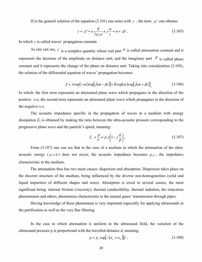
When the propagation of the ultra-sonic wave takes place in a medium in which energy losses
occur, the movement equation becomes:
2
22
2
2
xc
tR
t o ∂
∂=
∂
∂+
∂
∂ ξξρ
ξ , (3.102)
In which: R is the proportionality factor between the dissipation force and the speed of the particle in
the considered medium.
The general solution of the equation (3.102) is under the form:
( )[ ] ( )[ ]xtjBxtjA 'exp'exp γωγωξ −++= , (3.103)
Introducing (3.103) and its derivatives in (3.102) one obtains:
⎟⎟⎠
⎞⎜⎜⎝
⎛−±=
ωρω
γo
Rjc
1' , (3.104)
O 0,5 1 2 5 10 20 50 100
p
l
p = 1o1
2
20
If in the general solution of the equation (3.101) one notes with γ , the term 'γj one obtains:
βαω
ωργγ j
cjRj
o
+=±±==2
' , (3.105)
In which γ is called waves’ propagation constant.
As one can see, γ is a complex quantity whose real part α is called attenuation constant and it
represents the decrease of the amplitude on distance unit, and the imaginary part β is called phase
constant and it represents the change of the phase on distance unit. Taking into consideration (3.105),
the solution of the differential equation of waves’ propagation becomes:
( ) ( )[ ] ( ) ( )[ ]xtjxBxtjxA βωαβωαξ ++−−= expexpexpexp , (3.106)
In which: the first term represents an attenuated plane wave which propagates in the direction of the
positive x-s; the second term represents an attenuated plane wave which propagates in the direction of
the negative x-s.
The acoustic impedance specific in the propagation of waves in a medium with energy
dissipation Zs is obtained by making the ratio between the ultra-acoustic pressure corresponding to the
progressive plane wave and the particle’s speed, meaning:
⎟⎟⎠
⎞⎜⎜⎝
⎛−==
βα
ρ jcVpZ os 1
, (3.107)
From (3.107) one can see that in the case of a medium in which the attenuation of the ultra-
acoustic energy ( 0=α ) does not occur, the acoustic impedance becomes coρ , the impedance
characteristic to the medium.
The attenuation thus has two main causes: dispersion and absorption. Dispersion takes place on
the discreet structure of the medium, being influenced by the diverse non-homogeneities (solid and
liquid impurities of different shapes and sizes). Absorption is owed to several causes, the most
significant being: internal friction (viscosity), thermal conductibility, thermal radiation, the relaxation
phenomenon and others, phenomena characteristic to the natural gases’ transmission through pipes.
Having knowledge of these phenomena is very important especially for applying ultrasounds in
the purification as well as the very fine filtering.
In the case in which attenuation is uniform in the ultrasound field, the variation of the
ultrasound pressure p is proportional with the travelled distance d, meaning:
( )[ ]dpp dao αα +−= exp , (3.108)
21
and the variation of the intensity is proportional with p2, so:
( )[ ]dII dao αα +−= 2exp , (3.109)
In which: po; Io is the pressure and the initial intensity; aα - an attenuation coefficient due to the
absorption phenomenon; dα - an attenuation coefficient due to the diffusion phenomenon.
In the case of gases, the absorption coefficient aα can be considered as a sum of terms owed to
the previously mentioned causes, so:
Trctva ααααα +++= , (3.110)
In which: vα is the attenuation through absorption coefficient owed to viscosity; ctα - the attenuation
through absorption coefficient owed to thermal conductibility; rα - the attenuation through absorption
coefficient owed to radiation; αT - the attenuation through absorption coefficient owed to
intermolecular energy exchange.
According to Stokes and Rayleigh, the attenuation coefficient αv can be determined with the
relation:
ηρπ
α 3
22
38
cf
ov = , (3.111)
In which: η is the gas viscosity, which according to the kinetic theory of gases is:
3mlNmv
=η , (3.112)
where: N is the number of particles on volume unit; m – particle’s mass; vm – average speed of
particles; l – average travelled free.
Introducing (3.109) in (3.108) one obtains:
LfcNmvm
v ⋅= 22
2
1516
ρπ
α , (3.113)
for kl < 1 and :
fc
Nmvmv 2
0
2
3ρπ
α = , (3.114)
for kl > 1.
One can observe that in both cases the attenuation constant varies with the frequency.
22
During propagation of the ultrasonic waves in the medium compressions and rarefactions occur
and the temperature in the compression area becomes higher than that in the rarefaction area. Because
of this a leakage of the heat takes place followed by the production of an entropy and an energy
dissipation, from where an attenuation of the wave’s amplitude results. Due to the thermal
conductibility, the attenuation constant ctα has the form:
ov
Tct c
cc ρχ
χπα ⎟⎟
⎠
⎞⎜⎜⎝
⎛ −=
12 2
, (3.115)
In which: χ is the ratio of heats specific for constant pressure and constant volume; cv - heat specific at
constant volume; cT – thermal conductibility coefficient.
Together with heating the gas layers which are compressed a radiation of this heat also takes
place, fact which leads to a dissipation of the ultra-acoustic energy. The attenuation coefficient owed to
radiation αT, according to Stokes, can be calculated with the formula:
cq
T 21⎟⎟⎠
⎞⎜⎜⎝
⎛ −=
χχ
α , (3.116)
In which: q is the coefficient characteristic from the law of gas mass cooling, which has the form: qt
ot e−=θθ , (3.117)
where: θt is the excess of temperature at the time t; θ0 – excess of temperature at time zero.
The attenuation constant due to the losses through diffusion αd can be determined with the
relation:
δπ
α 2
434
98
cfd
d = , (3.118)
In which: d is the average diameter of solid impurities; δ - the diffusion factor which depends on the
material’s anisotropy (δ = 6,7.10-3 – for steel; δ = 3.10-4 – for aluminum; δ = 7,4.10-3 – for copper).
With the propagation of ultrasonic waves in solid mediums other phenomena which lead to
attenuation also appear, such as: the interaction between the ultrasound waves and electrons in metals,
the interaction between the ultrasonic waves and the thermal waves and others, which are of smaller
value and do not affect the relation substantially (3.105)
Along the volume absorption, in the field it is also necessary to know the absorption of the
ultrasonic waves at the separation surface of two mediums, case which corresponds in most active
applications of ultrasonic waves. Here, the notion of acoustic dissipation appears noted with δa, defined
as the ratio between the dissipated energy flow Φd, from the separation surface and the incident energy
flow ΦI, meaning:
23
i
da Φ
Φ=δ , (3.119)
Because in practice it is interesting to know what ultra-acoustic energy was sent in the second
medium, the ultra-acoustic absorption coefficient is defined (noted αa) as being the ratio between flow
retained by the separation surface and the incident energy flow:
i
ria Φ
Φ−Φ=α , (3.120)
In which: rΦ is the ultra-acoustic energy flow reflected in the first medium.
The ultra-acoustic absorption coefficient aα is tied to the specific acoustic impedance Zs, of the
separation plan by the relation: 2
1cZcZ
os
osa ρ
ρα
+
−−= , (3.121)
Replacing Zs / oρ c = r + jx in the relation (3.118) one obtains:
( ) 2214
xrr
a++
=α , (3.122)
Out of which one can see that α is an r function (resistance to the normalized entrance to Zs) and of x
(normalized entrance reactance to Zs).
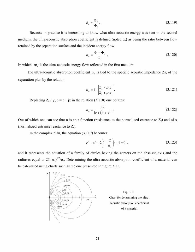
In the complex plan, the equation (3.119) becomes:
0121222 =+⎟⎟⎠
⎞⎜⎜⎝
⎛−++ rxr
oα , (3.123)
and it represents the equation of a family of circles having the centers on the abscissa axis and the
radiuses equal to 2(1-αa)1/2/αa. Determining the ultra-acoustic absorption coefficient of a material can
be calculated using charts such as the one presented in figure 3.11.
Fig. 3.11.
Chart for determining the ultra-
acoustic absorption coefficient
of a material
10
r
X 0,100,20
0,30
0,40
0,500,60
0,70
0,800,90
24
The absorption coefficient being a resistance function and the specific ultra-acoustic reactance
of that particular material, the function peaks are defined by the relation:
( )[ ] ( )[ ]( )[ ]
01
12414222
22
=−+
+−++=
∂
∂
xr
rrxrraα , (3.124)
and
( )[ ]0
1
8222=
−+−=
∂
∂
xr
rxxaα , (3.125)
From (3.125) one concludes that x = 0, which introduced in (3.124) leads to r = 1, which proves
that the absorption of an ultra-acoustic system is ultimate when the reactance is null, thus to resonance.
Experimentally it has been noted that the values of the ultra-acoustic absorption coefficient
differs from one material to another and even with the same material they depend on its mechanical and
geometrical characteristics, on frequency and on the formation manner of the separation plan by the
impurities existing in the carrier gas in which the ultrasonic field was created.
CHAPTER IV
THEORETICAL AND EXPERIMENTAL CONTRIBUTIONS TO THE
CALCULATION AND DESIGN OF ULTRA-ACOUSTIC SYSTEMS USED IN
THE CONSTRUCTION OF FILTERS AND SEPARATORS FOR NATURAL
GASES
Simple piezoceramic transducers and complex mechanical non-polarized piezoceramic
transducers
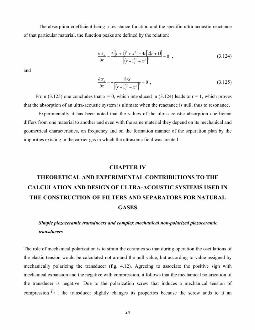
The role of mechanical polarization is to strain the ceramics so that during operation the oscillations of
the elastic tension would be calculated not around the null value, but according to value assigned by
mechanically polarizing the transducer (fig. 4.12). Agreeing to associate the positive sign with
mechanical expansion and the negative with compression, it follows that the mechanical polarization of
the transducer is negative. Due to the polarization screw that induces a mechanical tension of
compression T0 , the transducer slightly changes its properties because the screw adds to it an
25
additional mass and elasticity. Also, the piezoelectric constants of the ceramics are modified. The
amplification factor G of the transducer is also modified, becoming G ' and expressed as follows:
G '= 1− 2/√N , (4.79)
where:
N=Kef2 Q mQe , (4.80)
In order for the transducer to show optimum properties, the maximum domain of variation for
the effective coupling coefficient Kef is:
K 33≤ K ef≤2√2π
K 33 , (4.81)
Fig.4.12. The influence of mechanical polarization T0 over the maximum value of the mechanical tension Tmax, which can
be applied to the complex transducer during operation:
a – without mechanical polarization (T0 = 0); Tmax is limited by the resistance to the maximum mechanical expansion of the
piezoelectric ceramics Tf; b – with mechanical polarization; Tmax, is limited by the fatigue resistance of the mechanical
polarization screw.
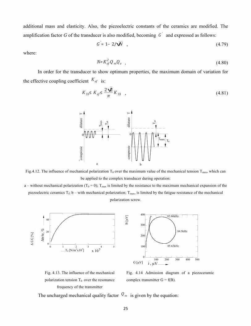
Fig. 4.13. The influence of the mechanical
polarization tension T0 over the resonance
frequency of the transmitter
Fig. 4.14 Admission diagram of a piezoceramic
complex transmitter G = f(B).
The uncharged mechanical quality factor Qm is given by the equation:
a b
0
Tdilatare
compresie
T Tmax et
0T
dilatare
compresie
T et
Tmax To
T (N / m ) x 10o
Δtr/
tr, %
2 70
01 2 3 4 5
20
40
0
100
200
300
400
G , µV
85.62kHz
100 200 300 400 500
84.5kHz
82.66kHz
B [µ
V]
T0 [N/m2x107]
Δ f r
/f r [%
]
G [µV]
26
Qm=ω0Rm
m2
m1(m1+m2) , (4.82)
where: Rm is the mechanical resistance (due to internal losses, friction, etc.), and m1 and m2
represent the masses of the reflector element and the radiant element respectively.
The piezoceramic element does not contribute significantly to the equivalent mass Mech .
(Mech=m1+m2/m1m2) of the vibrant system. The electrical quality factor Qe is typical for
piezoelectric ceramics and it depends on the action level of the transducer. Its variation domain is of
400…200 for a low level and it decreases to 50 for a high level.
Due to the mechanical polarization, the acoustic power per unit volume Pav , emitted by the
complex mechanically polarized transducer increases with the square value of the mechanical tension
of polarization T0 , being expressed as follows:
Pav=d332
K 332 (T+T0)2Q mω0η , (4.83)
where: T is the operating mechanical tension.
Figure 4.13 represents the influence of the polarization tension over the resonance frequency of
the mechanical polarized transmitter. For lower values of T0 , the relation Δf r/f r is very high ( f r is
the resonance frequency of the non-polarized transducer) until it reaches a certain value over which the
resonance frequency remains constant.
The material of the polarization screw must have similar characteristics to those that make up
the reflector element. The screw must ensure the mechanical polarization tension and must present high
compliance. Thus, by applying the mechanical polarization tension, great intensities and acoustic
powers may be obtained from the same acoustic structure. On the other hand, the tuning to the same
frequency of the transducers making up an assembly (for example, an acoustic siren) may be realized,
in the case of a fine tuning, not by machining the mechanical parts, which is an irreversible method, but
through the process of differential mechanical polarization of the transducers.
Experimental studies conducted on polarized transducers in which the direction of mechanical
polarization coincides with the direction of electrical polarization have shown the changes in properties
when passing from a state of null mechanical polarization (T0= 0) , called the minus state, to a state of
non-null tension T 0(0) called the plus state, as well as in the reverse scenario.
The behavior of the complex transducer exposed to mechanical polarization has been studied in
the following hypotheses: plane elastic waves; infinitely rigid metallic masses; the mechanical
27
polarization direction the same with the electrical polarization direction and with the axis of symmetry
of the transducers; the domain of the frequencies of experimentation set around the resonance
frequency; the negligible ceramics mass in relation to the metallic masses.
Under these conditions the equivalent impedance of transmitter Zt is given by the equation:
Zt = Rm+j (Lmω+ 1/ωC m) , (4.84)
The Zt impedance is represented by a series resonant circuit Rm, Lm, Cm, parallel with the
static capacity C 0 ; the R2 component is the sum of two terms R1+R2 , where R1 is the mechanical
loss resistance, and Rs is the load resistance. Parallel with C1 there is always an electrical loss
resistance Rd in the system.
Figure 4.14 represents the diagram G=f (B ) of a transmitter, G and B being the
conductance, respectively the susceptance, of the transmitter. If a change is introduced in the axial
polarization state, different effects emerge and, in particular, the parameters that characterize the
equivalent circuit of the transmitter change. These variations have been measured, as well as their
variation in time. From the moment of inducing mechanical polarization and with the help of a
previously established program, the diagrams of the corresponding admittance have been graphically
recorded with the help of an automatic device for measuring a x− y recorder, determining:
- the resonance frequency f r (at the point of maximum conductance Gm ;
- the frequencies which limit the band width (to 3 dB), f 1 , f 2 (conductance Gm/2 );
- the mechanical resonance frequency f 0 (zero susceptance) when the losses are low, which
results from:
ω02=
C m+C 1
LmC mC 1 , (4.85)
With the help of these parameters and the graphical representation of the electrical admittance,
the following parameters have been calculated:
- band width Δf=f 2− f 1 , (4.86)
- the mechanical quality factor Qm=f r/Δf ,
- the capacity C 1= (C a+C b)/2 , (4.87)
Capacities C a and C b correspond to the frequencies f 1 and f 2 respectively:
- dynamic capacity C m , represented as:
C m= (C a− Cb)/Q , (4.88)
28
- coupling coefficient kt , represented as:
kt=π/2√C m/ [2(C 1+C m)] , (4.89)
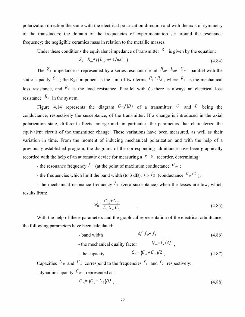
Figure 4.15 presents the reverse diameter of the circle of admittances, thus the values of the Rm resistance. It may be observed that the resistance Rm , by passing from the “-“ state to the “+”
state, increases considerably and after 104 minutes reaches 210 W. After the change in the axial
polarization state (‘’+’’ becomes “-“) and at the end of one week, the value of Rm decreases to 200 W,
an approximate value obtained in the reverse process. The change of the resonance frequency of
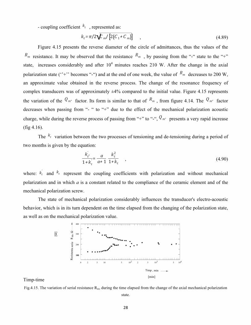
complex transducers was of approximately ±4% compared to the initial value. Figure 4.15 represents
the variation of the Qm. factor. Its form is similar to that of Rm , from figure 4.14. The Qm. factor
decreases when passing from “- “ to “+” due to the effect of the mechanical polarization acoustic
charge, while during the reverse process of passing from “+” to “-“, Qm. presents a very rapid increase
(fig 4.16).
The kt variation between the two processes of tensioning and de-tensioning during a period of
two months is given by the equation:
kt2'
1+kt' =
aa+ 1
kt2
1+kt , (4.90)
where: kt'
and kt represent the coupling coefficients with polarization and without mechanical
polarization and in which a is a constant related to the compliance of the ceramic element and of the
mechanical polarization screw.
The state of mechanical polarization considerably influences the transducer's electro-acoustic
behavior, which is in its turn dependent on the time elapsed from the changing of the polarization state,
as well as on the mechanical polarization value.
Timp-time Fig.4.15. The variation of serial resistance Rm, during the time elapsed from the change of the axial mechanical polarization
state.
R
, Ω
Timp , min
0
mR
ezis
tent
a se
rie
100100
200
300
400
2 5 510 102 2 5 103 1065
[min]
[Ω]
29
Timp-time
Fig. 4.16. The variation of the mechanical quality factor Qm, during the time elapsed from the change of the axial
mechanical polarization.
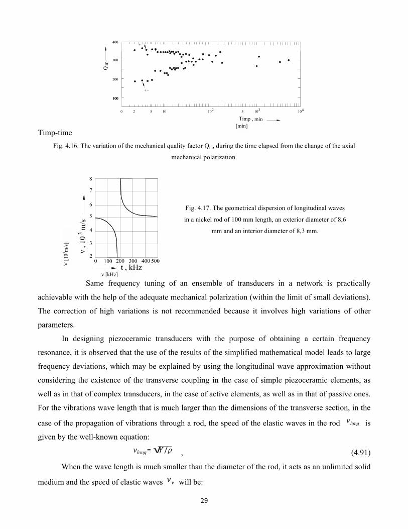
Fig. 4.17. The geometrical dispersion of longitudinal waves
in a nickel rod of 100 mm length, an exterior diameter of 8,6
mm and an interior diameter of 8,3 mm.
Same frequency tuning of an ensemble of transducers in a network is practically
achievable with the help of the adequate mechanical polarization (within the limit of small deviations).
The correction of high variations is not recommended because it involves high variations of other
parameters.
In designing piezoceramic transducers with the purpose of obtaining a certain frequency
resonance, it is observed that the use of the results of the simplified mathematical model leads to large
frequency deviations, which may be explained by using the longitudinal wave approximation without
considering the existence of the transverse coupling in the case of simple piezoceramic elements, as
well as in that of complex transducers, in the case of active elements, as well as in that of passive ones.
For the vibrations wave length that is much larger than the dimensions of the transverse section, in the
case of the propagation of vibrations through a rod, the speed of the elastic waves in the rod vlong is
given by the well-known equation:
νlong= √Y /ρ , (4.91)
When the wave length is much smaller than the diameter of the rod, it acts as an unlimited solid
medium and the speed of elastic waves νν will be:
Q
Timp , min0
m100100
200
300
400
2 5 10 102 5 103 104
+ -
+ -
2
t , kHz
v , 1
0 m
/s3
3
4
5
6
7
8
0 100 200 300 400 500
[min]
ν [kHz]
V [1
03 m/s
]
30
νν=√E (1− σ )
√ρ (1+σ)(1− 2σ) , (4.92)
where: σ is the Poisson coefficient, and νν is also called the speed of volumetric waves.
Experience has shown that in the case of wave lengths comparable to the dimensions of the
cross section of the rod there is a dispersion field, in which the speed of longitudinal waves depends on
the wave length. In figure 4.17 the propagation speed of longitudinal waves in a nickel rod is presented.
It is observed that in the bandwith 150 - 250 kHz, when the wave length is comparable with the
diameter of the rod, the dispersion of vibrations occurs (called geometrical dispersion because it is not
determined by the internal structure of the material, but by geometrical factors).
For the propagation of longitudinal waves in an infinitely long rod, the frequency equation is:
2μ∂2J 0(ha)
∂a2=p2 ρ∧ ¿
+ 2μJ 0 (ha)
¿¿
¿¿
2μk∂J 1(γa)∂a
= 0 , (4.93)
2k∂ J 0 (ha)∂a
2k2ω2ρμ
J 0 (γa )
which, through certain replacements and calculations, is reduced to the equation:
(x− 1)2ϕ (ha)− (βx− 1)[x− ϕ (γa)]= 0 , (4.94)
In equations (4.93) and (4.94) the factors signify the following: ,μ are the Lame constants;
ω− angular frequency; β= (1− 2σ)/(1− σ) ; σ - Poisson coefficient; x= (v/vlong)2(1+σ) ; λ - wave
length; a - rod radius; vlong - ultrasound speed inside the rod; v - wave speed;
h=k√βx− 1; γ=k√2x− 1; k= 2π/λ; ϕ (y )=yJ 0(y )/J 1(y ) , (4.95)
The equation (4.94) has the following form:
F (x, β, ka)= 0 , (4.96)
The properties of the function ϕ (y ) are: ϕ (y)=ϕ (− y), ϕ (0)= 2, limn− ∞(iy)=y , (4.97)
31
The zero points and the poles of function ϕ correspond with those of functions J 0 , J 1
respectively.
Supposing that (4.94) may be explicitly solved for x, x may be expressed under the following
form:
x=x (β,ka) , (4.98)
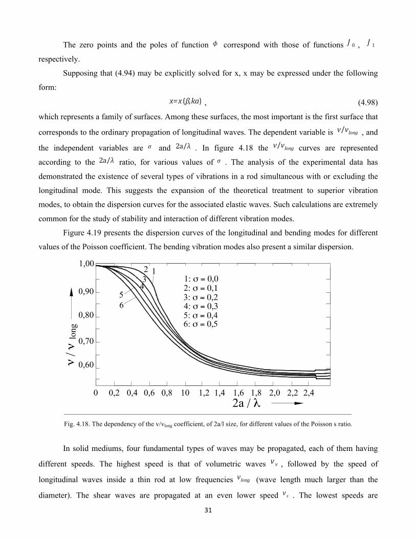
which represents a family of surfaces. Among these surfaces, the most important is the first surface that
corresponds to the ordinary propagation of longitudinal waves. The dependent variable is v/vlong , and
the independent variables are σ and 2a/λ . In figure 4.18 the v/vlong curves are represented
according to the 2a/λ ratio, for various values of σ . The analysis of the experimental data has
demonstrated the existence of several types of vibrations in a rod simultaneous with or excluding the
longitudinal mode. This suggests the expansion of the theoretical treatment to superior vibration
modes, to obtain the dispersion curves for the associated elastic waves. Such calculations are extremely
common for the study of stability and interaction of different vibration modes.
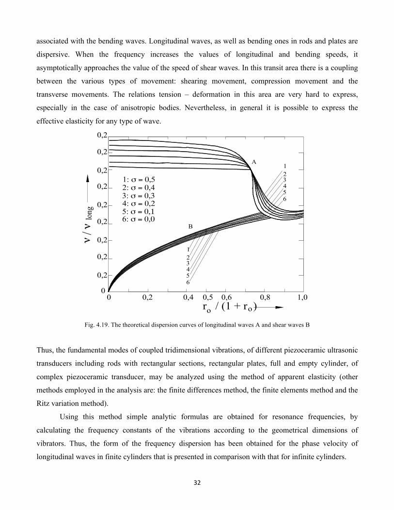
Figure 4.19 presents the dispersion curves of the longitudinal and bending modes for different
values of the Poisson coefficient. The bending vibration modes also present a similar dispersion.
Fig. 4.18. The dependency of the v/vlong coefficient, of 2a/l size, for different values of the Poisson s ratio.
In solid mediums, four fundamental types of waves may be propagated, each of them having
different speeds. The highest speed is that of volumetric waves vv , followed by the speed of
longitudinal waves inside a thin rod at low frequencies vlong (wave length much larger than the
diameter). The shear waves are propagated at an even lower speed vs . The lowest speeds are
0 0,2 0,4 0,6 0,8 10 1,2 1,4 1,6 1,8 2,0 2,2 2,4
0,60
0,70
0,80
0,90
1,00
2a / λ
ν / ν
long
56
432 1
1: σ = 0,02: σ = 0,13: σ = 0,24: σ = 0,35: σ = 0,46: σ = 0,5
32
associated with the bending waves. Longitudinal waves, as well as bending ones in rods and plates are
dispersive. When the frequency increases the values of longitudinal and bending speeds, it
asymptotically approaches the value of the speed of shear waves. In this transit area there is a coupling
between the various types of movement: shearing movement, compression movement and the
transverse movements. The relations tension – deformation in this area are very hard to express,
especially in the case of anisotropic bodies. Nevertheless, in general it is possible to express the
effective elasticity for any type of wave.
Fig. 4.19. The theoretical dispersion curves of longitudinal waves A and shear waves B
Thus, the fundamental modes of coupled tridimensional vibrations, of different piezoceramic ultrasonic
transducers including rods with rectangular sections, rectangular plates, full and empty cylinder, of
complex piezoceramic transducer, may be analyzed using the method of apparent elasticity (other
methods employed in the analysis are: the finite differences method, the finite elements method and the
Ritz variation method).
Using this method simple analytic formulas are obtained for resonance frequencies, by
calculating the frequency constants of the vibrations according to the geometrical dimensions of
vibrators. Thus, the form of the frequency dispersion has been obtained for the phase velocity of
longitudinal waves in finite cylinders that is presented in comparison with that for infinite cylinders.
00
0,2 0,4 0,5 0,6 0,8 1,0
0,2
0,2
0,2
0,2
0,2
0,2
0,2
0,2
0,2
1: σ = 0,52: σ = 0,43: σ = 0,34: σ = 0,25: σ = 0,16: σ = 0,0
ν / ν
long
r / (1 + r )o o
123456
A
B
123456

33
10
20
30
40
50
60
70
80
Re(ZT) Ω
10
20
30
40
50
60
Re(ZT) Ω
Re(ZT) Ω
lm(ZT) (Ω)
lm(ZT) (Ω)
lm(ZT) (Ω)
ConditiiForta de apasare Fa=0Nr. spire coloana =32
10 20 30 40 50 60 70 80 90 100 110
D
ω
ω
A
B
20385 Hz
20404Hz20430Hz ω0A
ω0B
10 20 30 40 50 60 70 80 90 100 110
ω
A ω0A
C
D
20680Hz
ω0B
o20450Hz
10 20 30 40 50 60 70 80 90 100 110
ω0B
ω0A
ω
20580Hz
20720Hz
ω
Fig. 4.20. The variation mode of „ZT” impedance for the concentrator transducer ensemble of the ultra-acoustic system used
in experiments.
Conditii - Conditions
Forta de apasare - Down force Fa = 0
Nr. spirale coloane - No. column coils = 32
34
Thus, for a rectangular rod with L, W, T dimensions, with L>>T and L>>W, the elasticity
equations are expressed under the following form:
z
S y= s11E Tx+ s12
E T y+ s13E Talignl S z= s21
E Tx+ s22E T y+ s23T z , (4.99)
0=S11E T x+ s12
E T y+ s13E T z ,
Using the notations:
ν12= −s12E
s11E ; ν13= −
s13E
s11E ; ν32= −
s13E
s33E ; n= −
T z
T y , (4.100)
the (4.99) equations are expressed under the following form:
Sy= s11E [(1− ν122 )+ν13(1+ν12)n]T y
,
S z= s33E [(1− ν31ν13)+ ν31(1+ν12)
n ]Tz (4.101)
and the elasticity modules Y y and Y z are:
Y y= {s11E [(1− ν122 )ν13(1+ν12)n]}− 1 , (4.102)
Y z= {s33E [(1− ν13ν31)+ ν31(1+ν12)n ]}− 1
, (4.103)
The vibrations resonance conditions for the secondary dimensions are offered by the following
expressions:
kyW=π; kzT=π , (4.104)
thus: koyW=π[(1− ν122 )+ν13(1+ν12)n]− 12 , (4.105)
kozT=π[(1− ν13ν31)+ ν31(1+ν12)n ]−12 , (4.106)
where:
ky=ω0vy; kz=
ω0vz; vy= √Y y
ρ ; vt= √Y zρ , (4.107)
koy=ω0√ρs11E koz=ω0√ρs33E ; ω0= 2πf0 , (4.108)
35
and f 0 is the resonance frequency.
From the (4.105) and (4.106) relations, the following expression is obtained:
WT= √s33Es11E ⋅√(1− ν13ν31)+ν31(1+ ν12n )(1− ν12)2+ν13 (1+ν12)n
, (4.109)
In the case of a rectangular plate, when the tension is Tz= 0 , we get:
Y x= [s11E (1+ ν12n )]− 1
; Y y= [s11E (1+ν12n)]− 1 ,
(4.110)
and
k0x L=π(1+ ν12n )−
12 ; k0yW=π(1+ν12n)
−12 , (4.111)
where:
kx=ω0vx; ky=
ω0v y; vx= √Y x
ρ ; vy= √Y yρ , (4.112)
k0x=k0y=ω0√ρs11E , (4.113)
From the relations at (4.111) the following expression is obtained:
WL= √1+ ν12n1+ν12n
, (4.114)
In the case of a finite full cylinder, of a dimension of 2l (l expressing its length) and 2a (a being
its diameter) – the most common case in ultrasound filtering, the elasticity equations in cylindrical
coordinates take the following form:
S z= s13E Tr + s13
E Tθ+ s33E T z
Sr= s11E Tr+ s12
E Tθ+ s13E Tz , (4.115)
Sθ= s12E Tr+ s11
E Tθ+ s13E T z
Under the cylindrical symmetry condition Tr=Tθ and with the notation: T z
Tr=TzTθ
= − n , (4.116)
36
the elasticity modules may be expressed under the following form:
Y z= [s33E (1+ 2ν31n )]− 1
; Y r = s33E [(1− ν122 )+ν13 (1+ν12n)]− 1 , (4.117)
By placing the longitudinal resonance condition, we get:
k0z⋅ l=π2 (1+ 2ν31n )−
12
, (4.118)
and the radial resonance condition becomes:
kr aJ 0(kr a)= (1− ν12)J 1(kr a) ,
(4.119)
where: k0z=ω0√ρs33E
If the following notation is made:
kr⋅ a=R1 , (4.120)
the (4.119) relation becomes:
kθr⋅ a=R1(1− ν122 )+nν13(1+ν12)− 12 , (4.121)
In these relations, the following has also been noted:
kr=ω0√Y r/ρ
; kθr =ω0√ρs11E , (4.122)
Making the ratio between relations (4.118) and (4.121) the following expression is obtained:
la= π2R1⋅√s11Es13E ⋅ (1− ν122 )+nν13 (1+ν12)1+ 2ν13/n
, (4.123)
an extremely important ratio in the dimensioning of any final active element of an ultra-acoustic system
used in the construction of ultrasonic filters.
In the case of an empty cylinder of a 2l length, with the exterior diameter a and the interior
diameter b, the elasticity modules are:
Y z[s33E (1+ 2 ν31n )]− 1
; Y r= {s11E [(1− ν122 )+ν13(1+ν12)n]}− 1 , (4.124)
The longitudinal resonance is obtained for the condition:
kθz⋅ l=π2(1+ 2ν31n )−
12 , (4.125)
37
where:
kθz=ω0√ρs33E , (4.126)
The radial resonance condition is expressed under the following form:
kr aN0(kr a)− (1− ν12)N1(kr a)kraJ 0(kr a)− (1− ν12)J 1(kr a)
=kr bN0 (kr b)− (1− ν12)N 1(krb)kr bJ 0 (krb)− (1− ν12)J 1(krb)
, (4.127)
where: Jn are the Bessel functions; Nn – the Newmann functions (n=1, 2,..)
With the notations:
kr a=R1; kr=ω0ν ; ω0= 2πf0 , (4.128)
From equation (4.127) we get the value of velocity v, given under the expression:
v= {ρs11E [(1− ν122 )+ν13(1+ν12)n]}−12 , (4.129)
and from relation (4.125) we get the following ratio:
2la= πR1⋅√s11Es33E ⋅ (1− ν122 )+ν13(1+ν12)n1+ 2ν31/n
, (4.130)
In the case of cylindrical symmetry, characterized by the equalities:
ν12=ν13=ν31=ν; s11E = s33
E = 1Y , (4.131)
the apparent elasticity modules become:
Y z=Y
√1+ 2ν/n; Y r=
Y(1− ν2)+ν (1+ν )n , (4.132)
and the longitudinal resonance condition is expressed under the following form:
kθz⋅ l=π2(1+ 2νn )−
12 , (4.133)
where:
kθz=ω0√ρY ; kr= ω0v ; ω0= 2πf0 , (4.134)
and the velocity v is expressed:
v=√ Yρ[(1− ν2)+ν (1+ν )n] , (4.135)
In the case of the symmetrical complex piezoelectric transducer (fig. 4.21) comprised of two
piezoelectric disks with 2 a1 diameters, hp height and characteristic acoustic impedance ρ1⋅ v1⋅ s1 , and
two identical passive metallic elements with h height, 2 a2 diameter and characteristic acoustic
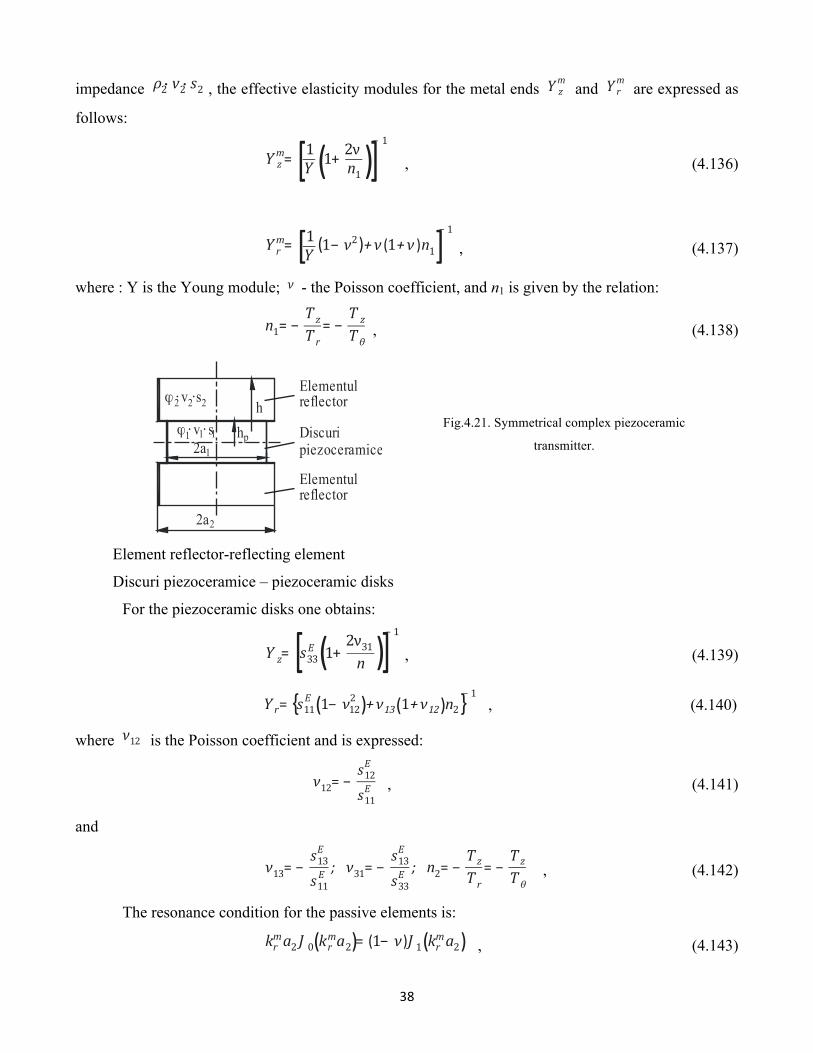
38
impedance ρ2⋅ v2⋅ s2 , the effective elasticity modules for the metal ends Y zm
and Y rm
are expressed as
follows:
Y zm= [1Y (1+ 2νn1 )]
− 1
, (4.136)
Y rm= [1Y (1− ν2)+ν (1+ν )n1]− 1 , (4.137)
where : Y is the Young module; ν - the Poisson coefficient, and n1 is given by the relation:
n1= −TzTr
= −T z
Tθ , (4.138)
Element reflector-reflecting element
Discuri piezoceramice – piezoceramic disks
Fig.4.21. Symmetrical complex piezoceramic
transmitter.
For the piezoceramic disks one obtains:
Y z= [s33E (1+ 2ν31n )]− 1
, (4.139)
Yr= {s11E (1− ν122 )+ν13(1+ν12)n2}− 1
, (4.140)
where ν12 is the Poisson coefficient and is expressed:
ν12= −s12E
s11E , (4.141)
and
ν13= −s13E
s11E ; ν31= −
s13E
s33E ; n2= −
TzTr
= −TzTθ
, (4.142)
The resonance condition for the passive elements is:
krma2 J 0(krma2)= (1− ν)J 1(krma2) , (4.143)
2a
ϕ ⋅ v ⋅ sh
h
2
2a11 1 1
ϕ ⋅ v ⋅s2 2 2
p
Elementulreflector
Discuripiezoceramice
Elementulreflector
39
where:
krm=ω0√ρ2/Y rm; ω0= 2πf0 , (4.144)
From the (4.143) relations, the following expression is obtained:
ω0a2√ρ2Y =R1m(1− ν2)+n1 ν(1+ν)
− 12 , (4.145)
where R1m
is the first root of equation (4.143).
The resonance condition for piezoceramic elements has the following form:
kr a1 J 0(kr a1)= (1− ν12)J 1(kra1) , (4.146)
where:
kr =ω0√ρ1Y , (4.147)
From the (4.146) relations, the following equality is obtained:
ω0a1√ρ1 s11E = R1{(1− ν122 )+n2ν13 (1+ν12)}− 12 , (4.148)
The resonance condition for the complex transmitter becomes:
tg(k1l1)tg(k2l2)=ρ1v1S1ρ2v2S2 , (4.149)
where it was noted:
k1=ω0v1; v1= √Y z
ρ1; k2=
ω0v2; v2= √Ymρ , (4.150)
and l1, l2 S1 and S2 are the dimensions of the ceramic and of the passive elements respectively.
The resonance condition (4.149) can be also expressed under the following form:
tg(k1 y0h)tg[k (1− y0)h]=ρ1v1a1
2
ρ2v2a22 , (4.151)
Experimentally it is observed that although the ceramic-reflector subset only transmits
longitudinal oscillations to the radiant element, longitudinal oscillations as well as transverse ones
appear in it due to the existent coupling in a solid medium These oscillations, according to Hooke's
generalized law, are propagated independently and the characteristic impedance of the radiant element
is a sum of the characteristic impedances corresponding to each type of generated radiations.
40
CHAPTER V
THEORETICAL AND EXPERIMENTAL CONTRIBUTIONS TO THE
CALCULATION, CONSTRUCTION AND EXECUTION OF ULTRASONIC
ENERGY CONCENTRATORS USED IN THE ULTRASOUND FILTERING OF
NATURAL GASES
Theoretical and experimental contributions to the finite elements analysis of
certain ultrasonic concentrators used in the ultrasound filtering of natural gases
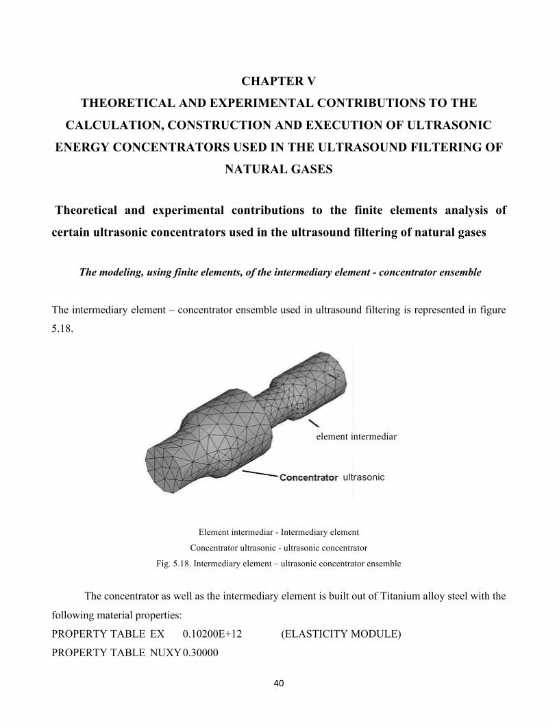
The modeling, using finite elements, of the intermediary element - concentrator ensemble
The intermediary element – concentrator ensemble used in ultrasound filtering is represented in figure
5.18.
Element intermediar - Intermediary element
Concentrator ultrasonic - ultrasonic concentrator
Fig. 5.18. Intermediary element – ultrasonic concentrator ensemble
The concentrator as well as the intermediary element is built out of Titanium alloy steel with the
following material properties:
PROPERTY TABLE EX 0.10200E+12 (ELASTICITY MODULE)
PROPERTY TABLE NUXY 0.30000
ultrasonic
element intermediar
41
PROPERTY TABLE ALPX 0.93600E-05
PROPERTY TABLE DENS 4850.0 (density)
PROPERTY TABLE KXX 7.4400
PROPERTY TABLE C 544.00
From the main menu, the type of structural analysis is chosen which also conditions calling
upon the libraries that contain the mesh elements.
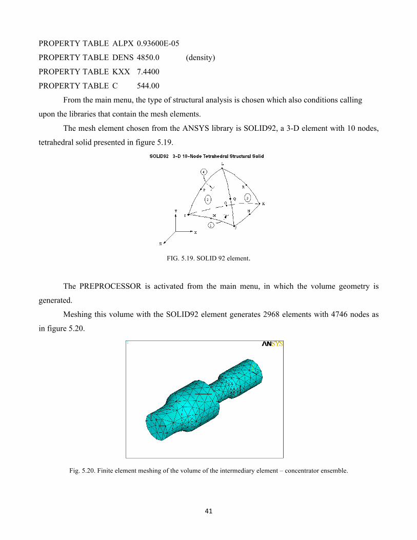
The mesh element chosen from the ANSYS library is SOLID92, a 3-D element with 10 nodes,
tetrahedral solid presented in figure 5.19.
FIG. 5.19. SOLID 92 element.
The PREPROCESSOR is activated from the main menu, in which the volume geometry is
generated.
Meshing this volume with the SOLID92 element generates 2968 elements with 4746 nodes as
in figure 5.20.
Fig. 5.20. Finite element meshing of the volume of the intermediary element – concentrator ensemble.
42
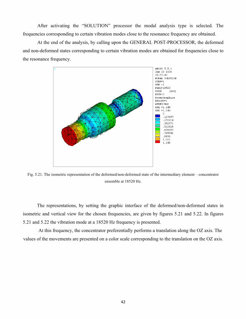
After activating the “SOLUTION” processor the modal analysis type is selected. The
frequencies corresponding to certain vibration modes close to the resonance frequency are obtained.
At the end of the analysis, by calling upon the GENERAL POST-PROCESSOR, the deformed
and non-deformed states corresponding to certain vibration modes are obtained for frequencies close to
the resonance frequency.
Fig. 5.21. The isometric representation of the deformed/non-deformed state of the intermediary element – concentrator
ensemble at 18520 Hz.
The representations, by setting the graphic interface of the deformed/non-deformed states in
isometric and vertical view for the chosen frequencies, are given by figures 5.21 and 5.22. In figures
5.21 and 5.22 the vibration mode at a 18520 Hz frequency is presented.
At this frequency, the concentrator preferentially performs a translation along the OZ axis. The
values of the movements are presented on a color scale corresponding to the translation on the OZ axis.
43
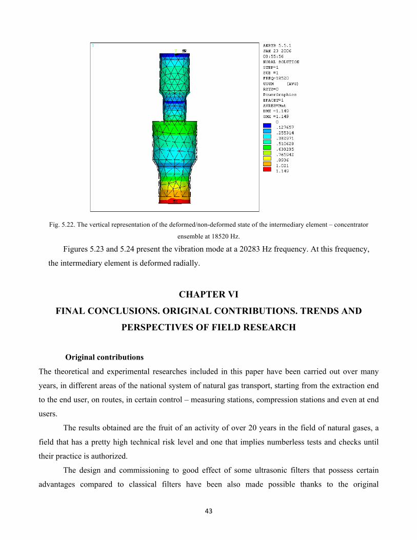
Fig. 5.22. The vertical representation of the deformed/non-deformed state of the intermediary element – concentrator
ensemble at 18520 Hz.
Figures 5.23 and 5.24 present the vibration mode at a 20283 Hz frequency. At this frequency,
the intermediary element is deformed radially.
CHAPTER VI
FINAL CONCLUSIONS. ORIGINAL CONTRIBUTIONS. TRENDS AND
PERSPECTIVES OF FIELD RESEARCH
Original contributions
The theoretical and experimental researches included in this paper have been carried out over many
years, in different areas of the national system of natural gas transport, starting from the extraction end
to the end user, on routes, in certain control – measuring stations, compression stations and even at end
users.
The results obtained are the fruit of an activity of over 20 years in the field of natural gases, a
field that has a pretty high technical risk level and one that implies numberless tests and checks until
their practice is authorized.
The design and commissioning to good effect of some ultrasonic filters that possess certain
advantages compared to classical filters have been also made possible thanks to the original
44
contributions of the author of the doctoral thesis in the field of theoretical research, as well as in that of
experimental research.
For reasons of technological secrecy and confidentiality, the paper contains only extracts of a
small portion of experimental results and principle schemes, since they include patentable elements.
Original contributions to the field of theoretical research
The main original contributions to the field of theoretical research could be the following:
Ø The original summary of the research concerning the purification and filtering of
natural gases;
Ø The analysis of the phenomena and effects that emerge upon the propagation of
ultrasonic waves in the natural gas medium that involve solid and liquid impurities of different
shapes and sizes;
Ø The analysis of the ultra-acoustic field specific to the filtering process in which
the medium is a natural gas permeated by solid and liquid impurities of different shapes and
sizes;
Ø Determining the reflection and ultra-acoustical transmission coefficient, ultra-
acoustical absorption and refraction coefficient created by the presence of the “slime” formed
by solid impurities entailed by natural gases;
Ø The calculation elements regarding the depth of retention, the minimum diameter
of the retained particle and the pressure drop at the top of the most important categories of
filtering: cyclonic, with an active filtering element;
Ø The calculation and design of certain ultra-acoustic systems used in the
construction of four categories of filtering;
Ø The MEF design of ultra-acoustic systems after determining the modes of
vibration at which the ultra-acoustic field for standing waves or the resonance mode activity is
obtained;
Ø Explaining the “ultrasonic agglomeration” phenomenon used in heightening the
retention level of fine particles and the level of “ultrasonic agitation” employed in cleaning the
active filtering element;
Ø The calculation and design of ultrasonic energy concentrators used as final parts
in the ultra-acoustic system and which have variable action and shapes that correspond to the
nature of the phenomena and effects that must occur in the ultrasonic field;
45
Ø The MEF design of ultrasonic energy concentrators and determining the
variation of the particle velocity amplitude along the concentrator, on which the “ultrasonic
agitation” phenomenon mainly depends;
Ø Establishing the conditions that need to be fulfilled by an ultrasonic filter for it to
perform the filtering process at high capacity and with increased efficiency.
Original contributions in the field of experimental research
The main original contributions in the field of experimental research are the following:
Ø The results obtained in the case of natural gas filtering using ultrasonic filtering;
Ø The design and creation of the model FCU-01 ultrasonic cyclone filter, with the
possibility of working in resonance mode by “ultrasonic agitation” or standing waves mode
with ultrasonic agglomeration;
Ø The design and creation of a vertical ultrasound gas filter, model FGVU-01 that
can work in a resonance mode and through ultrasonic agitation of the active filtering element;
Ø The design and creation of a horizontal ultrasonic cone filter, model FCOU-01,
that can retain liquid particles and solid impurities;
Ø The design and creation of a final ultrasound gas filter, model FFGU-01, that
realizes the total retention of the finest dust and water particles and that works in resonance
mode;
Ø The design and creation of four ultra-acoustic systems used in the construction of
ultrasonic filters.
The trends and perspectives of research in the field
The preoccupations of any researcher in the field of natural gases involve the increase of safety
in use and the decrease of the technical risk linked to the transportation from the extraction area to the
end user.
As the main source of energy for many areas of an economy, the efficient use of natural gases
implies the concentration of major research forces towards increasing it. Filtering and purification are
two essential operations that natural gases must undergo and their improvement is a constant process.
The main trends in this field of research are:
- discovering new natural gas deposits;
46
- the implementation of the filtering operation as close to the extraction area as possible to
limit the erosion of the other constituent elements of the National Gas Transmission
Company (SNTGN);
- the establishment of ultrasonic field parameters that would allow optimal filtering in as few
steps as possible;
- the implementation of certain simple and secure operation contributions;
- the reduction of exploitation and maintenance costs.
47
BIBLIOGRAFIE
1. Achnetchet, L.S.Blokh - Magnetostriction drive for microdisplacements, Machines and tooling. 2. Adaki, k., Arai, N. - A study on Low Frequency Vibratory Turning by Vutt of Tool; Doshisa, The
SERDU, vol. 27, no. 3, nov. 1986. 3. Adaki, k., Arai, N. - A study on Low Frequency Vibratory Drilling of Aluminium Deformed Layer
at the surface of Drilled Hole, Doshisa, The SERDU, vol. 30, no. 3, 1989. 4. Adil, N. Kinetics and stoichiometry of activated sludge treatment of a toxic organic wastewater,
J.W.P.C.F., februarie 1988. 5. Aitken, D., M.- Batch biological treatment of inhibitory substrates, Journal of Environmental
Engineering, vol 119, sept. 1993. 6. Akca, L.- A model for optimum design of activate sludge plans, Water Resources, Vol. 27, 9,
1993. 7. Akiyama. Y. - Present state of ultrasonic motors in Japan, J. Electron. Eng., 1987. 8. Alămoreanu, E - Metoda elementelor finite şi elementelor de frontieră, UPB, 1995. 9. Alder, R. - Simple theory of acoustic amplification, IEEE Trans. Sonics. Ultrason., vol 18, 1971. 10. Allik, H., Huges, T. - Finite element method for piezoelectric vibration, Int. J. Num. Meth. Eng.,
1979 11. Amza, Gh.; Barb, D.; Constantinescu, F.- Sisteme ultraacustice”, Editura Tehnică, Bucureşti
1988. 12. Amza, Gh., Drimer, D. - Calculul şi construcţia concentratorilor de energie ultrasonoră;
Tehnologii moderne în construcţia de maşini; Bucureşti I.P.B, nov. 1974. 13. Amza, Gh., Drimer, D., - Researches Concerning the Work of the Surfaces of the Metallic
Materials, Using the Ultrasonic Energy, London: Ultrasonic International Congress, 24-26, March, 1975.
14. Amza, Gh., Drimer, D. - The Design and Construction of Solid Concentrators of Ultrasonic Energy; London, Ultrasonics, no. 5; 1976, p. 222…226.
15. Amza, Gh.- Calculul şi construcţia blocurilor ultrasonice pe bază de ferite, Sesiunea „ Tehnologii moderne în industria constructoare de maşini, Galaţi, nov. 1977.
16. Amza, Gh.- The design and construction of solid concentrators for ultrasonic energy, Ultasonics, 14, 5, 1976.
17. Amza, Gh.- Ignat, M., Niţoi, D., Borda, C., Motoare ultrasonore pe bază de materiale magnetostrictive inteligente, Construcţia de maşini, nr. 8-9, 1997, pag. 53.
18. Amza, Gh. - Utilizarea ultrasunetelor în industrie, Editura I.P.B, 1978. 19. Amza, Gh., Drimer, D.- Maşina de durificat, netezit şi detensionat cu ajutorul energiei
ultrasonore. Brevet România, nr-69.218, inreg.10.05.76, publ. 08.04.80, pag.4, fig.4, ref. 3. 20. Amza, Gh., Popovici, V. -Nomograme pentru calculul concentratoarelor de energie ultrasonoră
combinat Conferinţa a IV-a de procese şi utilaje de prelucrare la rece, Timişoara 20-21 mai 1981.
21. Amza, Gh., Popovici, V., Roşca, I.- Nomograme de calcul şi construcţie a concentratoarelor combinate de energie ultrasonoră. Buletinul I.P. ,,Gheorghe Gheorghiu-Dej" Bucureşti - Seria Mecanică, Construcţii de Maşini, Transporturi-Aeronave, torn XLIV, nr.3 (iul-sept)/1982, pag-70-77, fig.5, tab.1, ref.5.
22. Amza, Gh.- Contribuţii teoretice şi experimentale privind tipurile constructive de blocuri ultrasonice, compunerea şi elementele constructive specifice prelucrării în câmp ultrasonor.
48
Buletinul I.P. ,Gheorghe Gheorghiu-Dej" Bucureşti - Seria Construcţii de Maşini, tom XLVI- XLVII, 1984-1985, pag.95-109, fig.9, tab.2, ref. 10.
23. Amza, Gheorghe-Ultrasunete de mari energii- Ed. Academiei, Bucureşti, 1984. 24. Amza, Gh.- Sisteme ultraacustice, Ed. Tehnică, Bucureşti, 1989. 25. Amza, Gh - Design Of ultrasonic transducers used in the structure of the ultrasonic cleaning
equipments. Modern Mechanical Design. September 18-20 1991. 26. Amza,Gh, ş.a - Nontraditional Manufacturing Processes, Editura ,,De Montfort University”,
Leicester, United Kingdom, 1994. 27. Amza, Gh. - A review of control and electronic systems in piezoelectric transducers- Ed. De
Montfort University, Workpackage 1, SPA Cap.1109, Leicester, UK, June 1995. 28. Amza, Gh., - Echipament universal cu ultrasunete folosit în chirurgie şi tratament, Contract de
cerectare nr. 836/1996. 29. Amza, Gh., ş.a, - Tehnologia materialelor, Editura Tehnică, Bucureşti, 1999 30. Amza, Gh., Nitoi, D., - Marinescu M., Borda, C., -Design and finite element method simulation of
the tool cone for the ultrasonic metal machining-Tehnologii Neconventionale- CITN 2000- Brasov 2-3 noiembrie
31. Amza Gh, ş.a, - Procese de operare, vol.Ed. BREN, Bucureşti 2000. 32. Amza Gh, Radu, C ş.a., - Procese de operare, vol.Ed. BREN, Bucureşti 2000. 33. Amza, Gh., Dumitru, G., Rândaşu, V., Amza, C., - Tratat de tehnologia materialelor, Ed.
Academiei, Bucureşti, 2000 34. Amza, Gheorghe, Popovici, Victor, Radu Constantin.-Finite element modelling and analysis of
simple ultrasonic horns, Buletin U.P.B. 2005. 35. Amza Gh., Buţu L., Marinescu M., Minca A., Borda C. - Theoretical resarch for monitoring
acoustic cavitations, Conferinţa cu participare internaţională 3-4 noiembrie 2005, Bucureşti. 36. Amza, Gh., Oprean C., Titu A. M.,Turc D. CONTRIBUTIONS REGARDIN DESIGNING AND
CONSTRUCTING ULTRASONIC HORIZONTAL CONE-SHAPEDFILTERS Proceedings of The2 International Conference on Quality and Innovation in Engineering and Management Cluj-Napoca 22 – 24 of November,2012: ISSN:1582-2559 (pag.299-302)
37. Oprean C.,Titu A. M., Amza, Gh., Turc D. CONTRIBUTIONS REGARDING DESIGNING AND CONSTRUCTION OF VERTICAL GAS FILTERS WITH ULTRASOUNDS
Proceedings of The International Conference on Quality and Innovation in Engineering and Management Cluj-Napoca 22–24 of November, 2012:ISSN:1582-2559 (pag.389-392)
38. Turc D., Oprean C., Amza Gh., Titu A.M., CONTRIBUTIONS REGARDING THE DESIGNING AND USAGE OF ULTRASONIC CYCLONE TYPE OF FILTERS
Proceedings of The2 International Conference on Quality and Innovation in Engineering and Management Cluj-Napoca 22 – 24 of November, 2012 ISSN:1582-2559 (pag.439-443)
39. Turc D., Oprean C., Titu A.M., Amza Gh. REGARDING FINAL GAS FILTERS WITH ULTRASOUNDS
Proceedings of The2 International Conference on Quality and Innovation in Engineering and Management Cluj-Napoca 22–24 of November, 2012 :ISSN:1582-2559 (pag.445-449)
40. Akulichev V.A. - The structure of solutions of equations describing pulsations of cavitation bubbles, Akusticheskii J. 13 (1967) 533 (in Russia).
41. Anderson C. And Collins H. – Distributed piezoelectric senso/actuator desfign for dynamic measurement/control of distributed parameter system , Journal of Sound Vibration, no. 138, pp. 17-34, 1991.
42. Anton, I., - Cavitaţia, Ed. Academiei, vol. I,II, Bucureşti 1984.
49
43. Ausländer, D., - Fizica proceselor activate cu ultrasunete, Ultraacustica ‘86, caietul 22, Timişoara, 1986.
44. Awad S.B. - An Ultrasonic Semi-AqueousAlternative to Vapor Degreasing, Precision Cleaning, I (1), p. 75, 1993.
45. Bailey T. And Hubbard J.E. Jr - Distruted piezoelectric polymer active vibration control of a cantilever beam – Journal of Guidance Control Dynamic no.8 605 – 11, 1985.
46. Bahadori, A., Vuthaluru, H.B.-Simple methodology for sizing of absorbers of TEG (triethylene glycol) gas dehydratation systems, Energy, 2009, 1-7.
47. Ballato A. and Smith J.G.,- Network representation for piezoelectric bimorphs, IEEE Trans.Ultrason.Ferroelec.Freq.Control, vol.38, no.6, Nov.1991
48. Barnett, S. B., - Negative effect of long duration pulsed ultrasonic irradiation, Ultrasound in Med., 3B, 1977.
49. Bathe, K., - Finite element procedures in engineering analysis, London: Prentice – Hall, 1982. 50. Begg, R. I., - Ultrasound production by rattus villosissimuss, Ultrasonics, 14, Hliffe Books,
London, 1973. 51. Berlincourt, D., - Piezoelectric cristals and ceramics, în Ultrasonic Traducers materials, Mattiat,
O., New York, Plenum Press, 1971. 52. Blehmann, I..I., Djanelidze, G. I., - Vibraţionnoe peremeşenie. „Nauka", 1964. 53. Blitz, J.,- Fundamental of Ultrasnincs, Butterworth, London, 1967. 54. Blitz J., Geoff Simpsons, - Ultrasonic Methods of Nondestructive testing – London 1980. 55. Blumenfeld, Maty., - Introducere în metoda elementelor finite, Ed. Tehnică 1995. 56. Borodinas, S., - Theoretical calculation and analysis of the compound ultrasonic cylindrical
concentrators, International Conference “ Vibroengineering – 98”, Lithuania 24 - 26 septembrie 1998.
57. Brown, B., Goodman, I.E - High intensity ultrasonics. Industrial aplicaţion, Hliffe, London, 1973.
58. Brignel, John., -Intteligent sensors systems, Institute of Publishing 1994. 59. Brown, B., Goodman, I.E., - High intensity ultrasonocs industrial applications; Hlife Books,
London, 1973. 60. Buţu, L. – Contribuţii privind curăţirea şi debavurarea cu ultrasunete a pieselor de mare precizie
- Teză de doctorat - UPB, Catedra Tehnologia Materialelor şi Sudare, Bucureşti, 2006. 61. Cahn, R. W., - Materials Science and Technology, vol 1…18, Editura Weinheim, New York,
1980. 62. Capineri et.al - Ultrasonic Transducer as Black-Box: Equivalent Circuit Synthesis and Matching
Network Design”, IEEE Trans. Ultrasonics, Ferroelectrics and Freq. Control, Vol. 40, No. 6, pp. 694-703, Nov 1993.
63. Carabogdan Gh.-Manualul inginerului termotehnician, Editera Tehnică, Bucureşti 1986. 64. Cheşa, I., - Alegerea şi utilizarea oţelurilor. Editura Tehnică, Bucureşti, 1984. 65. Chivers, R.C - A multiple nomogram for ultrasonic propagation calculation, Ultraacustics, 17,
1979. 66. Ciocan Cristy – Contribuţii privind prelucrarea materialelor dure şi extradure
neelectoconducătoare cu ajutorul energiei ultrasonore –Teză de doctorat -UPB, Catedra Tehnologia Materialelor şi Sudare, Bucureşti, 2004.
67. Cochran A., Reynolds P., Hayward G. – Progress in stacked piezocomposite ultrasonic transducers for low frequencz applications , Ultrasonic 36 )10)(1998) 969-977.
68. Cohen, B.S. şi Hering, S.V. Instrumente de Eşantionare a aerului, a 8-a ediţie, Conferinţa Americană a Ingieniştilor Industriali Guvernamentali, Cincinnati, OH, 1995.
69. Coulson, J. M., Richardson, J. F., Backhurst, J. R., Harker, J. H.-Chemical Engineering, Vol.2, Ed. Pergamon Press, 1980.
50
70. Crawford A.E. - The measurement of cavitation, Ultrasonics , vol. 2,1964, pg.120–123. 71. Crawley E.F. and de Luis J. – Use of piezoelectric actuators as elements of intelligent structures,
AIAAJ.25 1373-85, 1987. 72. Crawley, S. – Built-in diagnostics for identifying an anomaly in plates using distributed
piezoelectric sensors – Smart Materials Structures and Mathematical Issues, November, 1999 73. Creţu-Nica, M., - Activarea cu ultrasunete a mediilor lichide de lucru. Teză de doctorat,
Timişoara, 1999. 74. Dapino, M., Calkins, F., Flatau, A., Hall, D., Measured Terfenol – D material properties under
varied applied magnetic fields levels, Proceedings of SPIE 1996 Symposium on Smart Structures and Materials, 2717 – 66, San Diego, CA, March 1996.
75. Deaconescu, T., Ivan, M. – Instalatii de debavurat piese mici cu ajutorul ultrasunetelor, Conferinta „Optimizarea proiectarii si a tehnologiilor de prelucrare in constructia de masini” Bacau., 1997
76. Donald, R. C., - The Application of Finite Element Analysis to the Design of Ultrasonic Resonators, 1994.
77. Dixon R.K. -Carbon poolsn and flux global forest ecosystems, Scince 263, 1994. 78. Drăgan, O.; Iancu, C.; s.a. Ultrasunete de mari energii, Editura Academiei Bucureşti 1983 79. Dresnack, P., Metzger, I.-Oxigen response and Aeration in Streams, Journal of Water Pollution
Control Federation, nr. 25, 1973. 80. Drimer, D., Amza, Gh., - Tehnologia materialelor. Prelucrări cu ultrasunete, Bucureşti, I. P. B,
1983. 81. Drimer, D., Amza, Gh.- Ultrazvukovaia svarka tekstilnîii sinteticaskin i smeşanîh materialov,VI.
Nemopzkozi Hegoeztesi Tudomanyas Diekmeri Konferencia, Budapest, 21-26 iunie, 1976, p. 104-114.
82. Dumitrache, Fl., - Ultrazvukove bodove zvaranie niektorych kombinacii nezeleznycs kovov, Teză de doctorat Bratislava, 1976.
83. Dumitrache Rujinski, Al. – Cercetări teoretice şi experimentale privind utilizarea ultrasunetelor în procesul de tratare a cariilor – Teză de doctorat- UPB, Catedra Tehnologia Materialelor şi Sudare, Bucureşti, 2006.
84. Dumitru, E.; Nicolau, P; s.a. -Ultrasunetele, posibilităţi de utilizare în industria alimentară, Editura Ceres, Bucureşti 1990.
85. Eisner, E., - Design of sonic amplitude transformer for high magnification, J. Acoust. Soc. Am., Vol. 35, 1990.
86. Eisner, E., Saeger, J., - A longitudinaly resonant stub for vibrations of large amplitude, Ultrasonicics, vol. 3, 1965.
87. Engineering and Desing -Adsortion Desing Guide, Departament of the Army, US. Army Corps of Engineers, 1 Mar 2001.
88. Ensminger, D., - Ultrasonics. The low and high Intensity Application, Ed. Marcel Dekker Inc.,New York, 1978.
89. Errol Eernisse, Roger Ward, - Survey of Quartz Resonator Sensor Technologies, IEEE Transactions on Ultrasonics, Ferroelectrics, and Frequency Controls, 1990.
90. Fabien Josse, Zach Shana, David Radtke, - Analysis of Piezoelectric Bulk – Acoustic – Wave Resonators as Detectors in Viscous Conductive Liquids, IEEE Transactions on Ultrasonics, Ferroelectrics, and Frequency Controls,1990.
91. Florea J., Robescu, D., Petrovici, T. -Metode pentru determinarea debitului vehiculat de aeratoarele mecanice de suprafaţă, în volumul Colocviului de Echipamente pentru tratarea şi epurarea apelor, Bucureşti, 1980.
92. Florea, J., Robescu, D. -Hidrodinamica instalaţiilor de transport hidropneumatic şi de poluare a apei şi a aerului, Ed. Didactică şi Pedagogică, Bucureşti, 1983.
51
93. Fredrich, W., Lerch, R., Soldner, R., - Simulations of piezolectric lamb wave delay lines using a finite element method, IEEE Trans. Ultrason, Freq. Contr., vol. 37, 1990.
94. Fridman, V., Klopovsky, V. A., - The low liquid pressure acoustic hydrodynamic transducer and its use in sprayng processes, Ultrasonics, 14, 1976.
95. Fry, W., Fry, R., - Determination of absolute sound levels and acoustic absorption coefficients by thermocouple probes. J. Acoust. Soc. Am., 1954, 26, 294-297.
96. Gafitanu, M.; Focşa, V.; s.a. -Vibraţii şi zgomote, Editura Junimea, Iaşi 1980. 97. ***Gas Processors Suppliers Association (GPSA), „Engineering Data Book”, Eleventh Edition
1998, Section 20: Dehydration, pag. 20-4, 20-6, 20-9, 20-11, 20-12...15, 20-20, 20-33. 98. Gavrilaş, I., Marinescu, N. I., - Prelucrări neconvenţionale în construcţia de maşini, vol. I,
Editura Tehnică, Bucureşti, 1991. 99. Gavrilă, I. -Ultrasonarea acumulatoarelor electrice, Editura ştiinţifică şi enciclopedică, Bucureşti
1982. 100. Gauther J.C. -Reduction des emission d’oxides d’azote dans les chaudieres industrielles pas
utilisation de bruleurs a bas Nox, Revue Generale de Thermique, nr. 359, november 1991. 101. Gelet, A., Chapelon, J.-Y., Bouvier, R., Souchon, R., Pangaud, C., Abdelbrahim, A., Cathignol,
D., Dubernard, J.M., - Treatment of prostate cancer with transrectal focuse ultrasound: early clinical experience. Eur. Urol., 1996, 29, 174-183.
102. George Buchanan, John Peddieson, - Axisymetric Vibration of Infinite Piezoelectric Cylinders Using One Dimensional Finite Elements, IEEE Transactions on Ultrasonics, Ferroelectrics, and Frequency Controls, 1989.
103. Gerth, W.,A., Hemmingsen, E.,A.,- Heterogenous nucleation of bubbles in gas suprasaturated aqueous solutions, Journ. Coll. Interface Science, 74, 1980.
104. Ghersegal, D.A. s.a.- Aparate cu ultrasunete, Editura Tehnica, Bucuresti, 1962. 105. Ghersgal, D.A.; Fridman, V.M. „Aparate cu ultrasunete”, Editura tehnică, Bucureşti 1962. 106. Ghiculescu, D. – Prelucrări neconvenţionale, Editura Printech, Bucureşti, 2004. 107. Gîrleanu, G. – Contribuţii privind controlul nedistructiv al materialelor metalice cu ajutorul
actuatoarelor ultrasonore - Teză de doctorat - UPB, Catedra Tehnologia Materialelor şi Sudare, Bucureşti, 2003.
108. Gooberman, G. L. – Ultrasonics, Hart Publishing co., 1969. 109. Graham, E., - Cavitational bio-effects at 1,5 MHz, Ultrasonics, 9, 1980. 110. Hagedorn, P., Wallaschek, J., - Travelling wave ultrasonic motors, Part I: Working principle and
mathematical modelling of the stator, J. Sound and Vibration, vol. 1992. 111. Hagood S. And Ryall T. – Considerations in placement of piezocearmic actuators that are used
in structural vibration control , in Proc. 38th IEEE Conf. Decision Contr., Phoenix, AZ Dec. 1991, pag.1118-1123.
112. Hammit, F.,G., - Cavitation erosion. The state of the art and predicting capability, Appl. Mechanics Reviews, vol. 32, no. 6, 1979.
113. Hammit, F.,G., Okada, T., - Vibratory horn cavitation erosion comparasions, University of Michigan, 1980.
114. Hemsel, T., Wallasghek, J., - Piezoelectric linear vibration drive for high driving forces, International Conference ”Vibroengineerig - 98”, Lithuania24-26 septembrie 1998.
115. Harte, C. R., Baker, E. M., Purcell, H. H., Ing. Eng. Chem. 25, 528, 1933, citat de 3. 116. Hirata, H., Ueha, S., - Force factor design of a disk vibrators used for ultrasonic motors. J.
Acoust. Soc. Japan, vol 13, 1992. 117. Hirata, H., Ueha, S., - Revolution speed charateristics of an ultrasonic motors estimadet from the
pressure distribution of the motor, Japan, J. appl. Phyl., vol 31, 1992. 118. Hirata H., Sadayuki Ueha, - Characteristics Estimation of a Travelling Wave Type Ultrasonic
Motor, IEEE Transactions on Ultrasonics, Ferroelectrics, and Frequency Controls, 1993
52
119. Houdenko, B., Chpirt, E.- Areratory dlia ocistki stocinîh, vol. Ed. Maşghiz, Moscova, 1973. 120. Ibănescu, R., Poterasu, V., - Dynamical analysis of nonlinear mechanical vibrating system using
bond-grap and a simulation method, International Conference”Vibroengineerig - 98”, Lithuania 24 - 26 septembrie 1998.
121. Iclăzan, T. – Probleme ale sistematizării tehnice în aplicaţiile ultrasunetelor în tehnologie, Ultraacustica’86, Caietul 22, Timişoara, 1986.
122. Iclăzan, T., - Cercetări asupra parametrilor constructivi şi funcţionali la maşinile de prelucrat cu ultrasunete, Teză de doctorat, Timişoara 1975.
123. Iganat, M. – Contribuţii privind scanarea optică folosind actuatoare senzori ultrasonici pe bază de materiale inteligente, Teză de doctorat, UPB, Catedra tehnologia materialelor şi sudare, Bucureşti, 2000.
124. Ikeda, T., - Fundamentals of piezoelectric materials science, Ohm Co., Tokio, 1984 125. Inhaba, R., Tokushima, A., Ise, Y., - Piezoelectric ultrasonic motor, in Proc, IEEE Ultrason
Symp., 1987. 126. Ionescu, N., Dobre, M., - Cercetări privind prelucrarea materialelor dure prin vibroaşchiere;
Galaţi, Simpozionul de Tehnologii Speciale şi Neconvenţionale, Octombrie 1994. 127. Isarie, I. -Cercetări privind pulverizarea şi arderea carburanţilor lichizi în câmp ultrasonic”,
Sesiune de comunicări, Institutul de învăţământ superior Sibiu 1980. 128. Jan Soderkvist; - Electric Equivalent Circuit for Flexural Vibrations in Piezoelectric Materials;
IEEE Transactions on Ultrasonics, Ferroelectrics, and Frequency Controls, 1990. 129. Julian, R. Frederick., - Ultrasonic Engineering John Wiley&Sons, Inc.,New York-London-
Sydney, 1965 130. Jurkauskas, A.,- Diagnostics of Precise Mechanism Suports International Conference
”Vibroengineerig - 98” Lithuania 24 - 26 septembrie 1998. 131. Kafarov, V. -Fundamentals of Mass Transfer, Mir, Publishers, Moscow, 1975. 132. Kainth, G, S., ş.a. – Studiul prelucrării materialelor cu ultrasunete, Int. Journal of Machine-
Tools, G.B., No. 1, 1989. 133. Keller, A., - The influence of the cavitation nuclei spectrum on cavitation inception, IUTAM
Shymp. On Non steady flow of water at high speeds, Leningrad, 1971. 134. Kenjo, T., Shasida, T., - Introduction to Ultrasonics motors, Tokyo: Sogodenshi Syuppansya,
1991. 135. Kidger, M., Szilard, J., - A new ultrasonic lens, Ultrasonics, 14, 1976. 136. Kikuchi, Y., - Ultrasonic Traducers, Tokyo, Tohoku University Electronics Series, Corona
Publishing, 1999 137. Kikuchi, K. – Ultrasound/Their Application in Sience and Technology, New York, 1989. 138. Kidger, M., Szilard, J., - A new ultrasonic lens, Ultrasonics, 14, 1976. 139. Konash, P., Bastiaans, G., - Piezoelectric cristals as detectors in liquid cro matography, Anal.
Chem. Vol 52, 1980. 140. Krimholtz, R., Leedom, A., - New equivalent circuits for elementary piezoelectric transducers,
Electronlett, 1976; reflected ultrasound, Proc. IEEE. vol. 73, 1985. 141. Krohn, D.A. – Fiber Optic Sensors. Fundamental and Application- Instrument Society of
America, USA, 1988, pag. 111-128, 131-149. 142. Kumabe, J., - Vibration Cutting, Tokyo, Jikkyou Publishing Co, 1979. 143. Kumabe, J., Saito, T.,-Ultra-Precission Turning by applying ultrasonic vibration, J. J.S.P.E. 47,
no. 10/1981, p. 1252…1257. 144. Kumabe, J., - Application of ultrasonic vibratory Machining, Tool Engineering 30, no. 1/1986, p.
58…66. 145. Kumabe, J., - Ultrasonic Super-position Vibration Cutting of Ceramics, J.JSPE, vol 52, nr. 11,
1986, pag. 1851-1857.
53
146. K.A. Kunke, S. Locke, - Finite Element Analysis of Vibrational Mode in Piezoelectric Ceramic Disks, IEEE Transactions on Ultrasonics, Ferroelectrics, and Frequency Controls, 1990.
147. Lauterborn, W., - Cavitation and coherent optics, Cavitation and Inhomogenities in Underwater Acoustic, Gottingen, 1979.
148. Lăzăroiu Gh. - Sisteme de purificare totală a gazelor, al VII-lea Simpozion Tehnologii, instalaţii şi echipamente pentru îmbunătăţirea calităţii mediului, vol. 1, pag. 238-245, Bucureşti, 9-13 noiembrie 1998.
149. Lăzăroiu Gh.- Impactul poluanţilor asupra atmosferei, al VII-lea Simpozion Tehnologii, instalaţii şi echipamente pentru îmbunătăţirea calităţii mediului, vol. 1, pag. 246-253, Bucureşti, 9-13 noiembrie 1998.
150. Lăzăroiu Gh.- Protecţia atmosferei împotriva poluării, Editura PRINTECH, Bucureşti, 1998, ISBN 973-98453-9-8.
151. Lăzăroiu Gh.-Impactul CTE asupra mediului, Editura Politehnica Press, Bucureşti 2005. 152. Lăzăroiu Gh.-Tehnologii moderne de depoluare a aerului, Editura Agir, Bucureşti 2000. 153. Lăzăroiu Gh. -Protecţia atmosferei împotriva poluării, Editura Printech, Bucureşti 1998. 154. Lighthill M. J - Fourier Analysis and Generalized Functions. Cambridge: The University Press,
1970, pp. 42–44. 155. Leighton, T. G. - The Acoustic Bubble, pp73-74, Academic Press, London, (1994). 156. Lindackers D., Burmeister M., Roth P.- The reduction of Nox, 23rd symp on mbustion, The
Combustion Institute, 1990. 157. Lovik, A., - Acoustic measurement of the gas bubble spectrum in water, Cavitation and
Inhomogenities in Underwater Acoustic, Gottingen, 1980. 158. Macosko Ch. W.- Rheological Changes During Cosslinking- British Polymer Journal, 1985,17,
No.2 pag. 239-245. 159. Magheţi I. - Vibraţii mecanice, Editura Bren, 2003. 160. Manson, W., Wick, R., - A barium titanate transducer capable of large motion at ultrasonic
frequencies, J. acoust. Soc. Amer., vol 23, mar., 1951. 161. Manchester R.C - Precision Aqueous Cleaning System and Process Design, Precision Cleaning,
II (6), p. 11, 1994. 162. Martin C.J,. Law A.N.R - The use of thermistor probes to measure energy distribution in
ultrasound fields, Ultrasonics 18 (1980) 127–133. 163. Marinescu Marinela Nicoleta - Teza de doctorat Bucureşti, 2004 -Contributii privind procesarea
materialelor compozite inteligente. 164. Marinescu, N. -Prelucrări cu ultrasunete, Editura tehnică, Bucureşti 1986. 165. Markov,A.I.,-Ulitrazvukovoe rezanie trudnoabrabatîvaemîh materialov. Moskva: lzdatel'stvo
„Maşinostroenie", 1968, 367 pag., ref.460. 166. Maslanky, C.J. and Maslanky, S.P.-Instrumente de Examinare a Aerului, Van Nostrand Reinhold,
New York, 1993. 167. Masuda, M., - Ultraprecision Cutting of steel with CBN tools, J.S.P.E., no. 54/2/1986, p.
384…389. 168. Maurice, O’D., - The Ultrasonic Cleaning Process, The ASME Winter Annual Meeting, New
York, 1980. 169. Maximilian Fleischer, Dieter Stein, - New Type of Piezoelectric Ultrasonic Motor, IEEE
Transactions on Ultrasonics, Ferroelectrics, and Frequency Controls, 1989. 170. Medeksza, L.A., - Vibration Assisted Metal Turning, Oxford, 1986, p. 335…362. 171. Menke, Dean M., et al. - Demonstration of Alternative Cleaning Systems, Washington, D.C.,
U.S. EPA, August (U.S. EPA report number EPA/600/R-95/120), 1995 172. Mettin, R., Luther, S., Ohl, C.D., and Lauterborn,W - Acoustic cavitation structures and
simulations by a particle model,. Ultrasonics Sonochemistry 6, 25-29 (1999).
54
173. Michael, J. W., Mike, G., Naim, M., Ahmed, B., Experimental Study of 40, 68, and 132 kHz Ultrasonic, 1998.
174. Mishiro, S., - Ultrasonic Oscillation machining apparatus; United States Patent, no. 4856 391/1989.
175. Mishiro, S., Hamada, S., - Ultrasonic vibration cutting cutting; United States Patent, no. 4911 044/1990.
176. Mishiro, S., - Ultrasonic vibration and drive controle method thereaf, United States Patent, no. 4728843/1988.
177. Mocanu M., Lăzăroiu Gh. -Removel of liquid droplets and mists, The VIII-th Symposium Tehnologies, plants and eqiupament of environment quality, pag. 281-286, Bucharest, 9-12 november, 1999.
178. Mocanu M., Lăzăroiu Gh.- Removel of gaseus pollutans and odors, The VIII-th Symposium Tehnologies, plants and eqiupament of environment quality, pag. 287-296, Bucharest, 9-12 november, 1999.
179. Moffat A.S. -Resurgent forests can be breenhouse gas sponges, Scince 277, 1997. 180. Moholkar V.S., Sable S.P., Pandit A.B - Mapping the cavitation intensity in an ultrasonic bath
using the acoustic emission, AIChe J. 46 (2000) 684–694. 181. Moissenko, G.N., - Utilitrazvukovoe alimaznoe svertenie hrupkih materialov, Moskva, Stanki I
instrument nr. 4, 1982, p. 26…27. 182. Moriwaki, Toshimichi., Shamoto, Eiji., Inoue, Kenji., - Ultraprecision Diamond Turning of
Stainless Steel by Applying Ultrasonic Vibration. Journal of the Japan Society of Precision Engineering (Seimitsu Kogaku Kaishi), 57, nr.11 (nov), 1991, pag-1983-1988.
183. Moriwaki, Toshimichi., Shamoto, Eiji., Inoue, Kenji., - Ultraprecision Ductile Cutting of Glass by Applying Ultrasonic Vibration. Annals of the CIRP, vol-41, nr.1, 1992, pag. 141-144, fig. 13, ref. 13.
184. Moţoiu C., Lăzăroiu Gh., Apostol T. -Emisia de SO2 şi reducerea ei, Procceding Tempus – Envirom, Universitatea de vară, Protecţia mediului în România, pag. 331-334 Bucureşti, 6-10 iunie, 1994.
185. Mukaishima, H., - Application of piezoelectric ceramics, Tokyo, 1989. 186. Nagy, I. -Ultrasunete şi utilizarea lor, Editura ştiinţifică şi enciclopedică, Bucureşti 1982. 187. Nagai, K. and Konno, M. - Electromechanical vibrators and their application circuit element,
Corona Co., Tokyo, 1984. 188. Nakamura, K., Kurosawa, M., Ueha, S., - Design of a hybrid transducer-type ultrasonic motor,
IEEE Trans. Ultrason. Ferroelct.Frequency Control, no.40, pp.402-406, 1993. 189. Neppiras, E. A., High – Power ultrasonic – general, Ultrasonics, 13, 4, 1975. 190. Niemczewski B - A comparison of ultrasonic cavitation intensity in liquids, Ultrasonics, vol. 18,
no. 3, pp. 107–110, 1980. 191. Niemczewski, B - Estimation of the suitability of selected organic solvents for ultrasonic
cleaning, Ultrasonic 6, 1999, pg.149-156. 192. Nerubai, M.S., - Vliianie ulitrazvukovih kolebanii na mehaniceskie svoistva jiaroprocimh i
titanovîh splavov. Tez. dokl. mejdunar simpoziuma ,,Procinosti materialov i elementov konstrukţii pri zvukovîh i ulitrazvtlkovîh dastotah nagrujeniia", Kiev: „Naukova Durnka", 1984,118 pag.
193. Nesbitt W, Andrew McFarland , - Piezoelectric Materials for Ultrasonic Wave Applications, IEEE Transactions on Ultrasonics, Ferroelectrics, and Frequency Controls, 1997.
194. Nye, J., - Physical properties of crystals, Oxford, UK, Oxford University Press. 195. Noltingk B.E., Neppiras E.A. - Cavitation produced by ultrasonics, Proc. Phys. Soc. Lond. B 63
(1950) 674–685, 1950. 196. 190.O’Donoghue M.-The Ultrasonic Cleaning Process, Microcontamination, 2 (5),1984.
55
197. Ohnishi, K., Naito, K., Nakazava, T., - Ultrasonic linear actuator using coupled vibration of longitudinal and flexural vibrations, J., Acoust. Soc. Japan, vol. 47, 1991.
198. Oliver, D.E. -Diffusional Separation Processes, John Wiley, Sons, Inc. New York, 1966. 199. Onoe, M., et. Al. 1- Fundamentals of Solid Vibration Theory for Electrical and Electronic
Engineering, pp.117-57, Ohm Co., Tokyo. 200. Oroveanu T., David V., Stan Al. D., Trifan C. -Colectarea, transportul, depozitarea şi distribuţia
produselor petroliere şi gazelor, Editura Didactică şi Pedagogică, Bucureşti 1985. 201. Pană, T. -Absorbitori dinamici de vibraţii, Editura tehnică, Bucureşti 1984. 202. Papadakis E – Ultrasonic Instruments and Devices- Refrence for Modern Instrumentation,
Techniques and Technology, Academic Press New York, (ISBN 01253 19517), 2000. 203. Papuc, Gh. – Contribuţii privind proiectarea şi realizarea unor motoare ultrasonice folosite în
microrobotică, UPB-Teză de doctorat- Catedra Tehnologia Materialelor şi Sudare, Bucureşti, 2006.
204. Paul, H., Venkatesan, S., - Axisymetric vibration of a piezoelectric solid cilynder guided by a thin film, J. Acoust. Soc. Am., 1986.
205. Perkins, J. P., - Power Ultrasonic Equipment. Practice and Application, Sonochemistry Symposium, Warwick University, UK, 8-11 April 1986.
206. Perry, R., Green, G.- Perry’s Chemical Engineer’s Handbook, Section 2: Physical and Chemical Data, The McGraw Hill Company, 1999, ISBN 0-07-049841-5, pag.2-126.
207. Piazza t., Puskas W - The Ideal Ultrasonic Parameters for delicate part cleaning, august, 2001. 208. Popa, B., Iscrulescu, V. -Procese de ardere în câmp sonor, Editura tehnică, Bucureşti 1973. 209. Popilov, L.T., - Spravocinic po electriceskim I ulitrazvukovim metodom abrabotki materialov,
Maşinostroienie, Moskva, 1973. 210. Popovici, V., Amza, Gh., Niţescu, D., - Metodă şi instalaţie pentru măsurarea amplitudinii şi
solicitării concentratoarelor de energie ultrasonoră “Brevet de invenţie” Nr. 70941/28.03.1979. 211. Pust, L., - Vibration of non-linear system with feedback loop, International
Conference”Vibroengineerig - 98”, Lithuania 24 - 26 septembrie 1998. 212. Puşcoi N. -Exploatarea zăcămintelor de gaze, Editura Tehnică Bucureşti 1970. 213. Qi Q., William D., O’Brien Jr. - The Propagation of Ultrasonic Waves through a Bubbly Liquid,
IEEE, vol 42, no1, January 1995. 214. Ramutis Bansevicius, - Ultrasonic Motors, 1994 215. Rashmi, D., Modak, J.P., Junghare, A.S., - Dinamic of Flywhell Shaft and Laod Shaft of a
Mechanical System Involving Torsionally Flexible Finger Type Clutch Adopting State variable Approach, International Conference “Vibroengineering– 98” Lithuania 24-26 septembrie 1998.
216. Raşeev. D., Zecheru Gh.-Tehnologia fabricaţiei aparaturii-instalaţiilor statice-petrochimice şi de rafinării, Editura Tehnică, Bucureşti, 1982.
217. Reid, R., C., Prausnitz, J., M., Poling, B., E.-The Properties of Gases and Liquids, McGraw-Hill, 1987.
218. Reinhard Lerch, - Simulation of Piezoelectric devices by Two and Three – Dimensional Finite Elements, IEEE Transactions on Ultrasonics, Ferroelectrics, and Frequency Controls, 1997.
219. Rentz O. - Retour d’experience sus’l utilisation of SCR pour denitrifier les gas des Centrales allemandes, Institut Franco-Allemand de recherches sru l’Environnement, 1998.
220. Robescu, D.-Contribuţii teoretice şi experimentale la studiul epurării aepi. Teză de doctorat, Institutul Politehnic Bucureşti, 1975.
221. Robescu, D. -Instalaţii de depoluare a apei şi aerului, Institutul Politehnic Bucureşti, 1979. 222. Rotten, D., Levaillant J-M., - The ultrasonic examination to detect and diagnose breast
carcinomas. Analysis of the results obtain in 125 tumors using radiographic and ultrasound mammography. Ultrasound Obstet. Gynecol. 2, 202-214, 1992.
56
223. Rossing, T.D., and Fletcher, N.H. 1- Principle of vibration and sound, Springer Verlag, New York, 2004.
224. Rozenberg L. D - Relationship of the pulsations of cavitation voids to the emission of cavitation noise and shock-waves, in High-Intensity Ultrasonic Fields. L. D. Rozenberg, Ed. New York: Plenum, 1971, pp. 239–259.
225. Rugină, I., - Creşterea eficienţei sistemelor ultrasonice de înaltă intensitate, Bucureşti, Comisia de Acustică a Academiei, Caietul 21, 1986, pag. 24.
226. Sakharov, S., Iarionov, I., - Application of langasite crystals in monolite filters operating in shear modes, in proc. 1IEEE Freq. Contr. Symp. 1992.
227. Sashida, T., - Trial construction and operation of an ultrasonic vibration driven motor, OYO BUTURI, vol. 51, nr. 6, 1982.
228. Savii, G., Iclănzan, T., - Unele consideraţii asupra aplicării vibraţiilor ultrasonice în industrie, Timişoara, sept. 1975.
229. Savii, G., Iclănzan, T., Alimpie, I., - Echipamente tehnologice cu ultrasunete de utilizări industriale. Sesiunea de comunicări a Academiei RSR, Comisia de acustică, Bucureşti, 10 dec. 1979.
230. Sârbu, N. -Vibraţii mecanice, Litografia institutului de învăţământ superior Sibiu 1985. 231. Scheffel, E,A, M, Ştiucă, P., - Dispozitive cu ultrasunete, Bucureşti, Editura Tehnică Vol, I, II,
pag. 104…Bucureşti, 1989. 232. Scheffel, M.; Stiuca, P. -Dispozitive cu ultrasunete, Editura tehnică, Bucureşti 1989. 233. Scheible, K. -Development of a rationally based desing method for ultraviolet light disinfection
process, J.W.P.C.F., ianuarie 1987. 234. Schmidt, G., - Application of the finite element method to the extensional vibration of the
piezoelectric plates, in the mathematics of finite elements and Applications, J. Whiteman Ed. New Yorc: Academic Press 1973.
235. Scheffel,M, Stiuca, F- Dispozitive cu ultrasunete, vol I, II, Bucureşti, 1989. 236. Shibano Y., (1994) - Ultrasonic MicroDeburring Application, 3rd international Conference on
Precision Surface Finishing and Burr Technology. 237. Shuyu Lin, Fucheng Zhang - Measurement of ultrasonic power and electro-acustic effiecy of high
power transducers, Ultrasonics 37, 2000, pg. 549-554. 238. Shapery R.A.- Stress analysis of viscoelastic composite materials, Journal of Composites
Materials 1967, 1 : 228-67. 239. Shaulov A., Smith W.A. Singer B.- Composite piezoelectrics for ultrasonic transducers, IEEE
Trans. Ultrasonic Ferroelectric Freq. Control 33(6)(1986) 812- 821. 240. Shigeki, Toyama., ş.a. - Development of spherical ultrasonic motor. 1996. 241. Shoji, M., Seiji, H., - Ultrasonic cutting device, Brevet Japonia, nr. 62-24047/1987, Brevet SUA
nr. 4911044/1988. 242. Skelton, R.C., - Effect of Ultrasonic Vibration on the Turning Process. International Journal of
Machine Tool Design and Research, vol.9, 1969, pag. 363-374, fig. 14, ref.7. 243. Snow, D., - Innovation in Vibrational engineering: Business Aspects, International
Conference”Vibroengineerig - 98” Lithuania 24 – 26 septembrie 1998. 244. Stasa, F., - Applied finite element analysis for engineers, New York, Holt, Reinhart and Winston,
1985. 245. Stătulă, C. -Purificarea gazelor, Editura Ştiinţifică şi Enciclopedică, Bucureşti, 1984, pag. 165,
177, 271, 273, 394, 400, 401-402, 403, 419, 440, 445, 448. 246. Stoianovici, S., Robescu, D. -Calculul şi construcţia echipamentelor de oxidare a apelor, Ed.
Tehnică, Bucureşti, 1984. 247. Strauss, W. -Industrial Gas Cleaning, Pergamon Press, New York, 1966.
57
248. Šukelis, A, Ragulskis, M., - Investigation and Application of the Electro-Acoustic Generators, International Conference ”Vibroengineerig–98”, Lithuania 24 - 26 septembrie 1998.
249. Suslick K.S, .- The Chemical Effects of Ultrasound, Sci. Amer., 80, 1989. 250. Susani, M., Madersbacher, S., Kratzik, C., Vingers, L., Marberger, M., -Morphology of tissue
destruction induced by focused ultrasound. Eur. Urol., 1993, 23 (Suppl. 1), 34-38. 251. Suzuki, K., Kamo, S., Uno, M., - The eficiency of ultrasonicaly vibratory tapping proces, J.JSPE,
vol. 55, no.5/1989, p. 853…858. 252. Şomoghi, V., s.a. -Proprietăţi fizice utilizate în calcule termice şi fluidodinamice, U.P.G., Ploieşti
1997, pag. 169. 253. Taran, C. Şi Strătulă, C. -Procese difuzionale de separare, vol. 1, Inst. de petrol şi gaze, Ploieşti
1979. 254. Tiersten, H., - Linear piezoelectric plate vibration, New York: Plenum 1969. 255. Thompson, L., M., Eichholtz R.,L.- Ultrasonic Cleaning, Industrial Wastewater, 54-57
(May/June 1995). 256. Tomikawa Y., Nishitsuka N., Takano T., - Sensors and Materials, Clarendon Press, Oxford,
1989. 257. Trans. Am. Inst. Chem. Eng. 35, 211 (1939) citat de: Perry, R.H. and Green-Perry’s Chemical
Engineer’s Handbook, New York, 1997. 258. Trifan, C.-Distribuţia gazelor naturale prin reţele de conducte, Editura U.P.G. Ploieşti 2005. 259. Trifan, C. -Ditribuţia fluidelor prin conducte. Partea I-Ditribuţia gazelor naturale. Suport de
curs, U.P.G. Ploieşti 2003. 260. Trifan, C. -Transportul şi distribuţia gazelor naturale. Studii aprofundate-Suport de curs, U.P.G.
Ploieşti 2 261. Trifan, C., Albulescu M. -Hidraulica, transportul şi depozitarea produselor petroliere şi gazelor,
Editura Tehnică, Bucureşti 1999. 262. Trifan, C., Albulescu M., Neacşu S. -Elemente de mecanica fluidelor şi termodinamică tehnică,
Ed. U.P.G. Ploieşti 2005 263. Tulcan, Liliana. Georgeta., - Activarea ultrasonică a proceselor de netezire fină abrazivă, Teză
de doctorat, Timişoara, 2000. 264. Urick R. J .- Principles of Underwater Sound, 3rd ed. ~McGraw-Hill, New York, 1983, Chap. 4. 265. Van Wijngaarden, L. - On the Collective Collapse of a Large Number of Gas Bubbles in Water,
Proceedings I Ith International Congress of Applied Mechanics, Springer, Berlin, 854-861 (1964).
266. Vartanian, M.E., Hristaforian, S.S., Eghiazarian, R.A., - Vlianie ul'trazvukovîh kolebanii rezţa na teplovîe iavleniia v zone rezaniia pri tocenii trudnoabrabatîvaemîh materialov. Erevan. Politehn. Institut, Erevan, 1985, pag.7, ref.5.
267. Vobolis, J., - Investigation of Vibroacustic Processes in Sewing Machines, International Conference ”Vibroengineerig - 98”, Lithuania 24 - 26 septembrie 1998.
268. Voinea, R.; Voiculescu, D. -Elemente de vibraţii mecanice, Editura tehnică, Bucureşti 1973. 269. Voronin, A. A., Markov, A. I., - Vliianie ulitrazvukovîh kolebanii na protess rezaniia
jaroprocinîh splavov. Stanki i instrument, nr. 11/1960. 270. Wang, Lijiang., Sun, Fengchi., - An Experimental Study on Tool Life of Carbide Cutting Tips for
Ultrasonic Vibration Turning. Acta Armamentarii, nr.4(nov), 1988, pag.34-40, fig.4, tab.1, ref.4. 271. William, L., P., Timothy, P., - Designer Waveforms: Ultrasonic Technologies to Improve
Cleaning and Eliminate Damage. 272. Yamaguci, M., - Vibrator and ultrasonic motor emploing the same, US Patent 4983874, 1991. 273. Young F. R. - Cavitation. London: McGraw-Hill, 1989. 274. Young, M.J.R.; Winsper, C.E.; Sansome, D.H. -Radial mode vibrators for oscilatory metal
forming, Applied acoustic, 1970.
58
275. Zeqiri B., Ge´lat P.N., Hodnett M., Lee N.D. - A novel sensor for monitoring acoustic cavitation. Part I. Concept, theory and prototype development, IEEE Trans. UFFC 50 (2003) 1342–1350.
276. Zharii O.Y., - An exact mathematical model of a traveling wave ultrasonic motor, Cannes, 1994. 277. Zharii O.Y., - Model of an ultrasonic motor with friction-slip motion conversion, Acoust. Phys.,
no.39, pp.249-254, 1993. 278. Zimmermann, R., Thüroff, S., Chaussy, C., - High intensity focused ultrasound (HIFU) treatment
for localised prostate cancer - lower side effect rate by technical changes. Eur. Urol., 2000, 37, (Suppl. 2), 134.
279. Wolf, K. - The Truths and Myths about Water Based Cleaning - A Systems Approach to Choosing the Best Alternatives, Pollution Prevention Review, 4(2): 141-53 (Spring 1994).
280. Wells, P.N.T. – Biomedical Ultrasonics, 1987. 281. Wu Y.C. -Wet air oxidation of anaerobically digested sludge J.W.P.C.F., ianuarie 1987. 282. *** Prospecte SONICS. 283. *** Prospecte SONOBOND. 284. *** Prospecte DUKANE. 285. *** Prospecte BRANSON. 286. *** Prospecte KLN MECASONIC. 287. *** EMS Electro Medical Systems, - Catalog de aparate şi instrumente stomatologice activate cu
ultrasunete, 2006. 288. *** ANSYS. Analysis Guides, Huston, 1998. 289. *** - Curăţarea pieselor turnate, Traducere din limba maghiară, Bucureşti, 1968. 290. *** - Manual utilizare LabView. 291. Y.K. Yong, Plate - Element for the Static Temperature Behavior of Low- Frequency Quartz,
Resonators, IEEE Transactions on Ultrasonics, Ferroelectrics, and Frequency Controls, 1997.