Embed Size (px)
Citation preview
1FlneTek
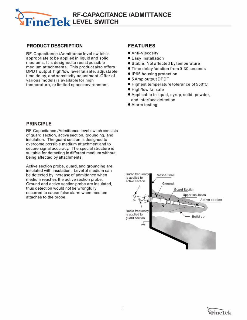
RF-Capacitance /Admittance level switch consists of guard section, active section, grounding, and insulation. The guard section is designed toovercome possible medium attachment and to secure signal accuracy. The special structure is suitable for detecting in different medium withoutbeing affected by attachments.
Active section probe, guard, and grounding are insulated with insulation. Level of medium can be detected by increase of admittance when medium reaches the active section probe.Ground and active section probe are insulated, thus detection would not be wrongfully occurred to cause false alarm when medium attaches to the probe.
RF-Capacitance /Admittance level switch is appropriate to be applied in liquid and solidmediums. It is designed to resist possible medium attachments. This product also offersDPDT output, high/low level failsafe, adjustabletime delay, and sensitivity adjustment. Offer ofvarious models is available for hightemperature, or limited space environment.
FEATURES
1 Anti-Viscosity
1 Easy Installation
1 Stable; Not affected by temperature
1 Time delay function from 0-30 seconds
1 IP65 housing protection
1 5 Amp output DPDT
1 Highest temperature tolerance of 550 C
1 High/low failsafe
1 Applicable in liquid, syrup, solid, powder,
and interface detection
1 Alarm testing
°
PRINCIPLE
Vessel wall
Active section
Radio frequency is applied to guard section
Radio frequency is applied to active section
Build up
Guard Section
Upper Insulation
PRODUCT DESCRIPTION
Ground
http: //www.fine-tek.com
e-mail: [email protected]
Tel: 886-2-22696789 Fax: 886-2-22686682
RF-CAPACITANCE /ADMITTANCE LEVEL SWITCH
2
FlneTek
EXAMPLE
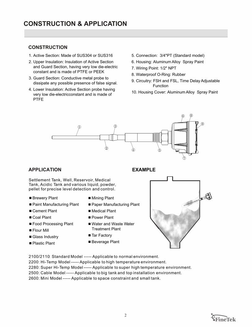
Settlement Tank, Well, Reservoir, Medical Tank, Acidic Tank and various liquid, powder,pellet for precise level detection and control.
4 Brewery Plant
4 Paint Manufacturing Plant
4 Cement Plant
4 Coal Plant
4 Food Processing Plant
4 Flour Mill
4 Glass Industry
4 Plastic Plant
2100/2110: Standard Model ----- Applicable to normal environment.
2200: Hi-Temp Model ----- Applicable to high temperature environment.
2280: Super Hi-Temp Model ----- Applicable to super high temperature environment.
2500: Cable Model ----- Applicable to big tank and top installation environment.
2600: Mini Model ----- Applicable to space constraint and small tank.
4 Mining Plant
4 Paper Manufacturing Plant
4 Medical Plant
4 Power Plant
4 Water and Waste Water
Treatment Plant
4 Tar Factory
4 Beverage Plant
APPLICATION
CONSTRUCTION
CONSTRUCTION & APPLICATION
1. Active Section: Made of SUS304 or SUS316
2. Upper Insulation: Insulation of Active Section
and Guard Section, having very low die-electric
constant and is made of PTFE or PEEK
3. Guard Section: Conductive metal probe to
dissipate any possible presence of false signal.
4. Lower Insulation: Active Section probe having
very low die-electricconstant and is made of
PTFE
5. Connection: 3/4"PT (Standard model)
6. Housing: Aluminum Alloy Spray Paint
7. Wiring Point: 1/2" NPT
8. Waterproof O-Ring: Rubber
9. Circuitry: FSH and FSL, Time Delay Adjustable
Function
10. Housing Cover: Aluminum Alloy Spray Paint
FlneTek3
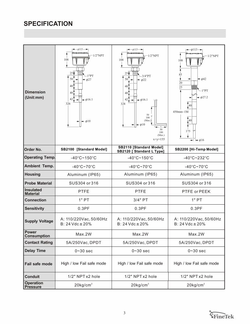
SPECIFICATION
SUS304 or 316 SUS304 or 316
PTFE PTFE or PEEK
5A/250Vac, DPDT 5A/250Vac, DPDT
-40 C 150 C° ~ ° -40 C 232 C° ~ °
-40 C 70 C° ~ ° -40 C 70 C° ~ °
3/4" PT 1" PT
0.3PF 0.3PF
SUS304 or 316
PTFE
5A/250Vac, DPDT
-40 C 150 C° ~ °
-40 C 70 C° ~ °
1" PT
0.3PF
Max.2W Max.2W Max.2W
High / low Fail safe mode High / low Fail safe mode
1/2" NPT x2 hole1/2" NPT x2 hole
220kg/cm
220kg/cm
High / low Fail safe mode
1/2" NPT x2 hole
0~30 sec
Aluminum (IP65) Aluminum (IP65)Aluminum (IP65)
SB2100 [Standard Model] SB2200 [Hi-Temp Model]SB2120 [ Standard L Type]SB2110 [Standard Model]
Dimension
(Unit:mm)
Probe Material
Housing
Ambient Temp.
Operating Temp.
InsulatedMaterial
Connection
Sensitivity
Supply Voltage
PowerConsumption
Contact Rating
Delay Time
Fail safe mode
Conduit
OperationPressure
220kg/cm
y
x
50100(Max.)
50100(Max.)
x+y=155
1/2"NPT
φ113
108
3/4"PT
328
40
42
φ22
φ16.1
φ10
40
50
25
1/2"NPT
φ113
108
1"PT
φ27.2
φ42
φ16
40
25
40
85
450mm~1M
20
175
1/2"NPT
φ113
108
1"PT
326
40
42
φ27
φ16.1
φ10
40
50
25
0~30 sec 0~30 sec
A: 110/220Vac,
20%
50/60Hz
B: 24 VdcK
A: 110/220Vac,
20%
50/60Hz
B: 24 VdcK
A: 110/220Vac,
20%
50/60Hz
B: 24 VdcK
FlneTek4
-40 C~150 C° ° -40 C~150 C° °
SUS304 or 316 SUS304 or 316
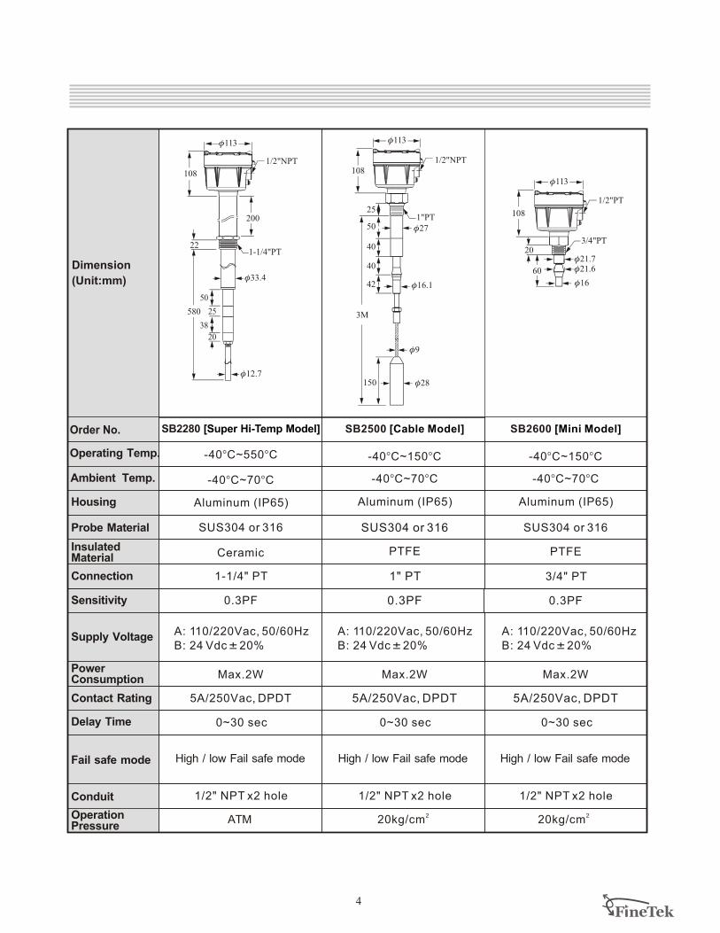
SB2500 [Cable Model] SB2600 [Mini Model]
1" PT 3/4" PT
Aluminum (IP65) Aluminum (IP65)
High / low Fail safe mode High / low Fail safe mode
0.3PF 0.3PF
1/2" NPT x2 hole1/2" NPT x2 hole
5A/250Vac, DPDT 5A/250Vac, DPDT
-40 C~70 C° ° -40 C~70 C° °
220kg/cm
220kg/cm
SB2280 [Super Hi-Temp Model]
SUS304 or 316
High / low Fail safe mode
Ceramic
Aluminum (IP65)
5A/250Vac, DPDT
-40 C~550 C° °
-40 C~70 C° °
1-1/4" PT
0.3PF
1/2" NPT x2 hole
ATM
Max.2W Max.2W Max.2W
Dimension
(Unit:mm)
Probe Material
Housing
Ambient Temp.
Operating Temp.
InsulatedMaterial
Connection
Sensitivity
Supply Voltage
PowerConsumption
Contact Rating
Delay Time
Fail safe mode
Conduit
OperationPressure
PTFE PTFE
1/2"NPT
φ113
108
580
22
50
38
φ33.4
φ12.7
1-1/4"PT
200
25
20
φ113
108
1"PT
40
42
φ27
φ16.1
40
50
25
1/2"NPT
φ9
φ28
3M
150
1/2"PT
φ113
108
3/4"PT
φ21.7φ21.6
φ16
60
20
0~30 sec 0~30 sec 0~30 sec
A: 110/220Vac,
20%
50/60Hz
B: 24 VdcK
A: 110/220Vac,
20%
50/60Hz
B: 24 VdcK
A: 110/220Vac,
20%
50/60Hz
B: 24 VdcK
FlneTek5
WIRING DIAGRAM
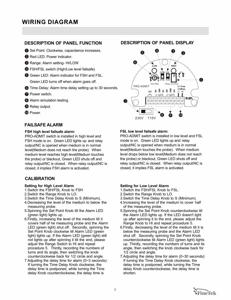
DESCRIPTION OF PANEL FUNCTION
Set Point: Clockwise, capacitance increases.
Red LED: Power indicator.
Range: Alarm setting- HI/LOW
FSH/FSL switch (High/Low level failsafe)
Green LED: Alarm indicator for FSH and FSL.
Green LED turns off when alarm goes off.
Time Delay: Alarm time delay setting up to 30 seconds.
Power switch.
Alarm simulation testing.
Relay output.
Power.
FAILSAFE ALARM
FSH high level failsafe alarm:
PRO-ADMIT switch is installed in high level and
FSH mode is on. Green LED lights up and relay
output/NC is opened when medium is in normal
level(Medium does not reach the probe). When
medium level reaches high level(Medium touches
the probe) or blackout, Green LED shuts off and
relay output/NC is closed. When relay output/NC is
closed, it implies FSH alarm is activated.
CALIBRATION
DESCRIPTION OF PANEL DISPLAY
Setting for Low Level Alarm1.Switch the FSH/FSL Knob to FSL.2.Switch the Range Knob to LO.3.Switch the Time Delay Knob to S (Minimum).4.Increasing the level of the medium to cover half
of the measuring probe. 5.Spinning the Set Point Knob counterclockwise till
the Alarm LED lights up. If the LED doesn't light up after spinning it to the end, please adjust the Range Knob to HI and repeat procedure 5.
6.Firstly, decreasing the level of the medium till it is below the measuring probe and the Alarm LED shut off. Secondly, spinning the Set Point Knob counterclockwise till Alarm LED (green light) lights up. Thirdly, recording the numbers of turns and its angle, then switching the knob clockwise back for1/2 circle and angle.
7.Adjusting the delay time for alarm (0~30 seconds):If turning the Time Delay Knob clockwise, the delay time is postponed, while turning the Time delay Knob counterclockwise, the delay time is shorten.
115V230V
PRO-ADMIT
FSL low level failsafe alarm:
PRO-ADMIT switch is installed in low level and FSL
mode is on. Green LED lights up and relay
output/NC is opened when medium is in normal
level(Medium touches the probe). When medium
level drops below low level(Medium does not reach
the probe) or blackout, Green LED shuts off and
relay output/NC is closed. When relay output/NC is
closed, it implies FSL alarm is activated.
Setting for High Level Alarm1.Switch the FSH/FSL Knob to FSH2.Switch the Range Knob to LO.3.Switch the Time Delay Knob to S (Minimum).4.Decreasing the level of the medium to below the
measuring probe. 5.Spinning the Set Point Knob till the Alarm LED
(green light) lights up. 6.Firstly, increasing the level of the medium till it
covers half of he measuring probe and the Alarm LED (green light) shut off. Secondly, spinning the Set Point Knob clockwise till Alarm LED (green light) lights up. If the Alarm LED (green light) still not lights up after spinning it till the end, please adjust the Range Switch to HI and repeatprocedure 5. Thirdly, recording the numbers of turns and its angle, then switching the knobcounterclockwise back for 1/2 circle and angle.
7.Adjusting the delay time for alarm (0~3 seconds):If turning the Time Delay Knob clockwise, the delay time is postponed, while turning the Time delay Knob counterclockwise, the delay time is
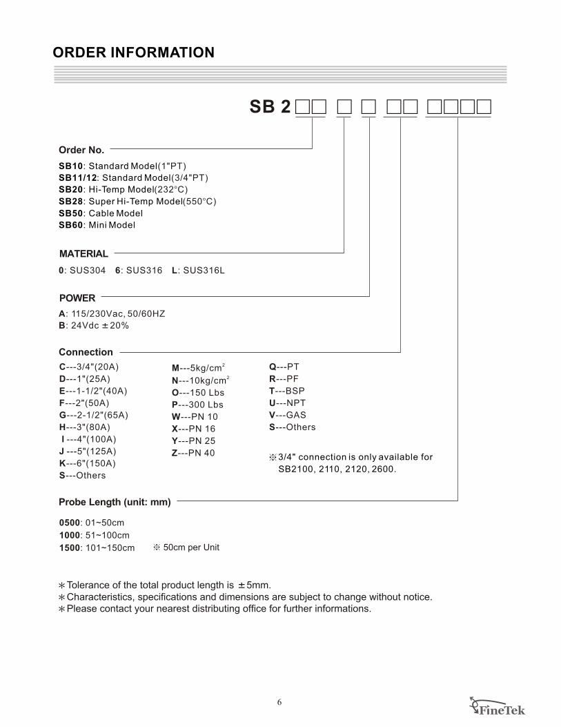
C---3/4"(20A)
D---1"(25A)
E---1-1/2"(40A)
F---2"(50A)
G---2-1/2"(65A)
H---3"(80A)
I ---4"(100A)
J ---5"(125A)
K---6"(150A)
S---Others
2M---5kg/cm
2N---10kg/cm
O---150 Lbs
P---300 Lbs
W---PN 10
X---PN 16
Y---PN 25
Z---PN 40
Probe Length (unit: mm)
SB 2 99 9 9 99 9999
Q---PT
R---PF
T---BSP
U---NPT
V---GAS
S---Others
FlneTek6
ORDER INFORMATION
Connection
SB10: Standard Model
SB11/12: Standard Model
SB20: Hi-Temp Model
SB28: Super Hi-Temp Model
SB50: Cable Model
SB60: Mini Model
(1"PT)
(3/4"PT)
(232°C)
(550°C)
Order No.
3/4" connection is only available for
SB2100, 2110, 2120, 2600.
0500: 01~50cm
1000: 51~100cm
1500: 101~150cm 50cm per Unit
POWER
MATERIAL
0: SUS304 6: SUS316 L: SUS316L
A: 115/230Vac, 50/60HZ
B: 24Vdc K20%
Tolerance of the total product length is K5mm.
Characteristics, specifications and dimensions are subject to change without notice.
Please contact your nearest distributing office for further informations.