Embed Size (px)
Citation preview

RFConnectorSolutions
RFConnectorSolutions
C o n n e c t i n g I n n o v a t i o n t o A p p l i c a t i o n ®®
Winchester Electronics was established in 1941
and is today a global leader in the design,
development, and deployment of interconnect
technology. Headquartered in Wallingford,
Connecticut, USA, Winchester operates
worldwide with modern, electronically linked
design, manufacturing, sales, and distribution
facilities in the United States, Mexico, China,
Malaysia, and Japan.
Winchester’s competitive advantage is our ability
to solve even the most difficult interconnect
problems, deploy design solutions globally to
meet the customer’s manufacturing needs,
and offer true supply chain management
techniques to deliver value through our
high-mix, low-volume manufacturing
model. Our global IT infrastructure
and worldwide communication
capabilities allow for continuous
information access in support of
customer opportunities. With
the recent acquisition of
Kings Electronics, we have
expanded our technological
capabilities and broadened
our market base and
product offering.
Now a Winchester Electronics
brand, KINGS was originally founded in
1947 and has provided numerous contributions
to the advancement of connector technology,
including the K-Grip® crimp style connector, True
75 Ohm BNC connectors, and the industry
standard Tri-Loc® triaxial camera connector
series. This long-trusted RF brand is highly
regarded by customers in the Broadcast,
Telecommunications, and Commercial and
Military Aviation industries.
With over 125 years of collective industry
experience, Winchester Electronics and the
KINGS® Brand create value for our customers
by offering a proven combination of quality
products, efficient manufacturing, dedicated
service, and inventive design solutions.
In addition to the KINGS® Brand RF Connectors,
Winchester Electronics also manufactures a wide
variety of PCB and Power Connectors, as well as
value-added cable and electromechanical
assemblies for customers in the Wireless
Infrastructure, Computer, Industrial, and Medical
Equipment industries.
Realizing its responsibility to the environment,
every Winchester Electronics facility is ISO
Certified and all of our products are manufac-
tured in compliance with the European Union
RoHS directive.
Providing superior products built to stringent
specifications, the new Winchester Electronics is a
valuable extension of your product development
team. With the ability to rapidly develop
engineered solutions at reduced costs and time-
to-market, we can help your company maintain
its competitive edge.
Connecting Innovation To Application®
3
Connector Selection Guide 0450 Ohm BNC Series 05BMA Series 16C Series 20K-Loc® Series 24MCX Series 26MMCX Series 29N Series 32QC-N Series 42SC Series 44SMA Series 47QC-SMA™ Series 59SMB Series 61TNC Series 66TRB Series 81TRT Series 8410 KV Series 8620 KV Series 88HN Series 90MHV Series 93SHV Series 9675 Ohm BNC Series 99Long Barrel BNC 102Patch Plugs 104Patch Cord Assemblies 106Tri-Loc® 108International Tri-Loc® 1131.0/2.3 DIN 116Audio/Video Patching System 118Mid-Size Video Jacks & Jackfields 120Standard-Size Video Jacks & Jackfields 122Populated Video Jackfields 124Tools & Accessories __________________________ 127
Strain Relief Boots 128Installation Tools 130Splices 131
Mounting Holes 132Cable Procedures 134Cable Reference Table 180KINGS® Cable Groups 184Glossary 186Military to KINGS® Cross-Reference Chart 187Part Number Index 190
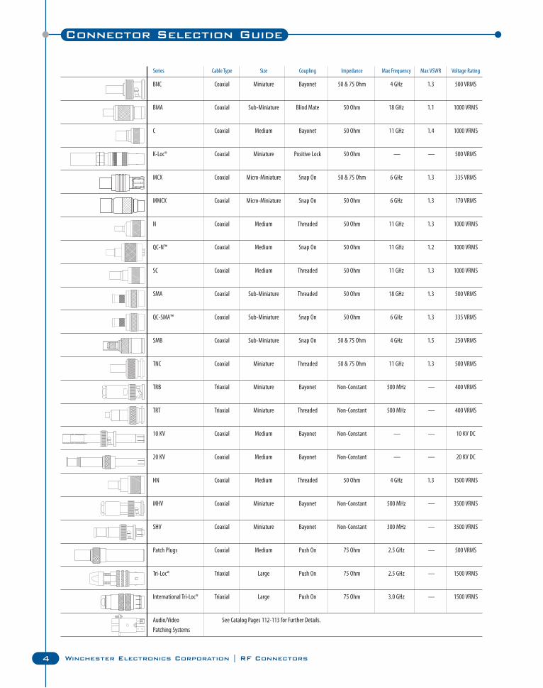
Series Cable Type Size Coupling Impedance Max Frequency Max VSWR Voltage Rating
BNC Coaxial Miniature Bayonet 50 & 75 Ohm 4 GHz 1.3 500 VRMS
BMA Coaxial Sub-Miniature Blind Mate 50 Ohm 18 GHz 1.1 1000 VRMS
C Coaxial Medium Bayonet 50 Ohm 11 GHz 1.4 1000 VRMS
K-Loc® Coaxial Miniature Positive Lock 50 Ohm — — 500 VRMS
MCX Coaxial Micro-Miniature Snap On 50 & 75 Ohm 6 GHz 1.3 335 VRMS
MMCX Coaxial Micro-Miniature Snap On 50 Ohm 6 GHz 1.3 170 VRMS
N Coaxial Medium Threaded 50 Ohm 11 GHz 1.3 1000 VRMS
QC-N™ Coaxial Medium Snap On 50 Ohm 11 GHz 1.2 1000 VRMS
SC Coaxial Medium Threaded 50 Ohm 11 GHz 1.3 1000 VRMS
SMA Coaxial Sub-Miniature Threaded 50 Ohm 18 GHz 1.3 500 VRMS
QC-SMA™ Coaxial Sub-Miniature Snap On 50 Ohm 6 GHz 1.3 335 VRMS
SMB Coaxial Sub-Miniature Snap On 50 & 75 Ohm 4 GHz 1.5 250 VRMS
TNC Coaxial Miniature Threaded 50 & 75 Ohm 11 GHz 1.3 500 VRMS
TRB Triaxial Miniature Bayonet Non-Constant 500 MHz — 400 VRMS
TRT Triaxial Miniature Threaded Non-Constant 500 MHz — 400 VRMS
10 KV Coaxial Medium Bayonet Non-Constant — — 10 KV DC
20 KV Coaxial Medium Bayonet Non-Constant — — 20 KV DC
HN Coaxial Medium Threaded 50 Ohm 4 GHz 1.3 1500 VRMS
MHV Coaxial Miniature Bayonet Non-Constant 500 MHz — 3500 VRMS
SHV Coaxial Miniature Bayonet Non-Constant 300 MHz — 3500 VRMS
Patch Plugs Coaxial Medium Push On 75 Ohm 2.5 GHz — 500 VRMS
Tri-Loc® Triaxial Large Push On 75 Ohm 2.5 GHz — 1500 VRMS
International Tri-Loc® Triaxial Large Push On 75 Ohm 3.0 GHz — 1500 VRMS
Audio/Video See Catalog Pages 112-113 for Further Details.
Patching Systems
Connector Selection Guide
4 Winchester Electronics Corporation | RF Connectors
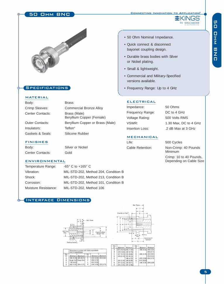
50 Ohm BNC
Specifications
MATERIAL
Body: BrassCrimp Sleeves: Commercial Bronze AlloyCenter Contacts: Brass (Male)
Beryllium Copper (Female)Outer Contacts: Beryllium Copper or Brass (Male)Insulators: Teflon®
Gaskets & Seals: Silicone Rubber
FINISHES
Body: Silver or NickelCenter Contacts: Gold
ENVIRONMENTAL
Temperature Range: -65° C to +165° CVibration: MIL-STD-202, Method 204, Condition BShock: MIL-STD-202, Method 213, Condition BCorrosion: MIL-STD-202, Method 101, Condition BMoisture Resistance: MIL-STD-202, Method 106
• 50 Ohm Nominal Impedance.
• Quick connect & disconnect bayonet coupling design.
• Durable brass bodies with Silver or Nickel plating.
• Small & lightweight.
• Commercial and Military-Specifiedversions available.
• Frequency Range: Up to 4 GHz
Connecting Innovation to Application®
5
50 O
hm B
NC
ELECTRICAL
Impedance: 50 OhmsFrequency Range: DC to 4 GHzVoltage Rating: 500 Volts RMSVSWR: 1.30 Max, DC to 4 GHzInsertion Loss: .2 dB Max at 3 GHz
MECHANICAL
Life: 500 CyclesCable Retention: Non-Crimp: 40 Pounds
MinimumCrimp: 10 to 40 Pounds, Depending on Cable Size
Interface Dimensions
6 Winchester Electronics Corporation | RF Connectors
50 Ohm BNC
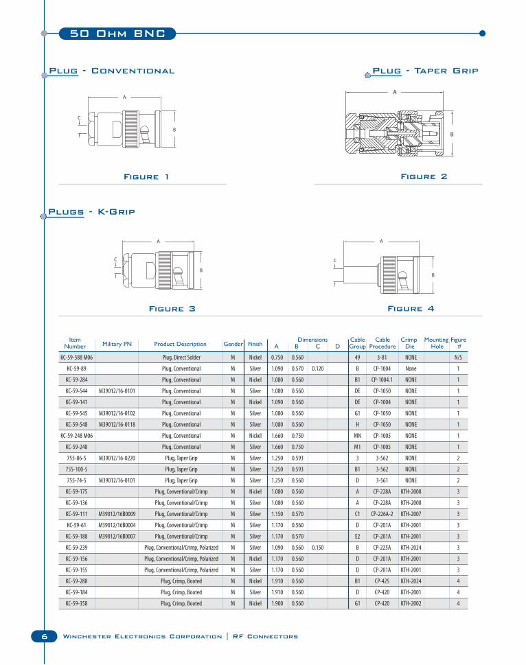
Figure 1 Figure 2
Figure 3 Figure 4
KC-59-588 M06 Plug, Direct Solder M Nickel 0.750 0.560 49 3-81 NONE N/S
KC-59-89 Plug, Conventional M Silver 1.090 0.570 0.120 B CP-1004 None 1
KC-59-284 Plug, Conventional M Nickel 1.080 0.560 B1 CP-1004.1 NONE 1
KC-59-544 M39012/16-0101 Plug, Conventional M Silver 1.080 0.560 DE CP-1050 NONE 1
KC-59-141 Plug, Conventional M Nickel 1.090 0.560 DE CP-1004 NONE 1
KC-59-545 M39012/16-0102 Plug, Conventional M Silver 1.080 0.560 G1 CP-1050 NONE 1
KC-59-548 M39012/16-0118 Plug, Conventional M Silver 1.080 0.560 H CP-1050 NONE 1
KC-59-248 M06 Plug, Conventional M Nickel 1.660 0.750 MN CP-1005 NONE 1
KC-59-248 Plug, Conventional M Silver 1.660 0.750 M1 CP-1005 NONE 1
755-86-5 M39012/16-0220 Plug, Taper Grip M Silver 1.250 0.593 3 3-562 NONE 2
755-100-5 Plug, Taper Grip M Silver 1.250 0.593 B1 3-562 NONE 2
755-74-5 M39012/16-0101 Plug, Taper Grip M Silver 1.250 0.560 D 3-561 NONE 2
KC-59-175 Plug, Conventional/Crimp M Nickel 1.080 0.560 A CP-228A KTH-2008 3
KC-59-136 Plug, Conventional/Crimp M Silver 1.080 0.560 A CP-228A KTH-2008 3
KC-59-111 M39012/16B0009 Plug, Conventional/Crimp M Silver 1.150 0.570 C1 CP-226A-2 KTH-2007 3
KC-59-61 M39012/16B0004 Plug, Conventional/Crimp M Silver 1.170 0.560 D CP-201A KTH-2001 3
KC-59-188 M39012/16B0007 Plug, Conventional/Crimp M Silver 1.170 0.570 E2 CP-201A KTH-2001 3
KC-59-239 Plug, Conventional/Crimp, Polarized M Silver 1.090 0.560 0.150 B CP-225A KTH-2024 3
KC-59-156 Plug, Conventional/Crimp, Polarized M Nickel 1.170 0.560 D CP-201A KTH-2001 3
KC-59-155 Plug, Conventional/Crimp, Polarized M Silver 1.170 0.560 D CP-201A KTH-2001 3
KC-59-288 Plug, Crimp, Booted M Nickel 1.910 0.560 B1 CP-425 KTH-2024 4
KC-59-184 Plug, Crimp, Booted M Silver 1.910 0.560 D CP-420 KTH-2001 4
KC-59-358 Plug, Crimp, Booted M Nickel 1.900 0.560 G1 CP-420 KTH-2002 4
Item Dimensions Cable Cable Crimp Mounting FigureNumber Military PN Product Description Gender Finish A B C D Group Procedure Die Hole #
Plug - Conventional Plug - Taper Grip
Plugs - K-Grip
Connecting Innovation to Application®
7
50 Ohm BNC50 O
hm B
NC
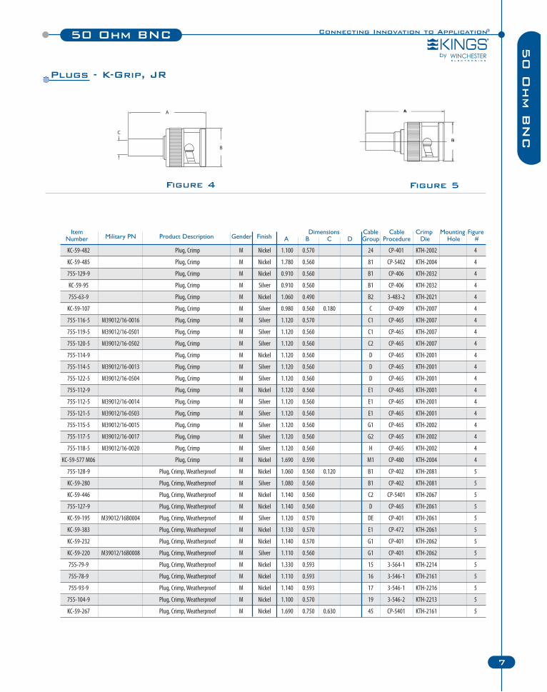
KC-59-482 Plug, Crimp M Nickel 1.100 0.570 24 CP-401 KTH-2002 4
KC-59-485 Plug, Crimp M Nickel 1.780 0.560 81 CP-5402 KTH-2004 4
755-129-9 Plug, Crimp M Nickel 0.910 0.560 B1 CP-406 KTH-2032 4
KC-59-95 Plug, Crimp M Silver 0.910 0.560 B1 CP-406 KTH-2032 4
755-63-9 Plug, Crimp M Nickel 1.060 0.490 B2 3-483-2 KTH-2021 4
KC-59-107 Plug, Crimp M Silver 0.980 0.560 0.180 C CP-409 KTH-2007 4
755-116-5 M39012/16-0016 Plug, Crimp M Silver 1.120 0.570 C1 CP-465 KTH-2007 4
755-119-5 M39012/16-0501 Plug, Crimp M Silver 1.120 0.560 C1 CP-465 KTH-2007 4
755-120-5 M39012/16-0502 Plug, Crimp M Silver 1.120 0.560 C2 CP-465 KTH-2007 4
755-114-9 Plug, Crimp M Nickel 1.120 0.560 D CP-465 KTH-2001 4
755-114-5 M39012/16-0013 Plug, Crimp M Silver 1.120 0.560 D CP-465 KTH-2001 4
755-122-5 M39012/16-0504 Plug, Crimp M Silver 1.120 0.560 D CP-465 KTH-2001 4
755-112-9 Plug, Crimp M Nickel 1.120 0.560 E1 CP-465 KTH-2001 4
755-112-5 M39012/16-0014 Plug, Crimp M Silver 1.120 0.560 E1 CP-465 KTH-2001 4
755-121-5 M39012/16-0503 Plug, Crimp M Silver 1.120 0.560 E1 CP-465 KTH-2001 4
755-115-5 M39012/16-0015 Plug, Crimp M Silver 1.120 0.560 G1 CP-465 KTH-2002 4
755-117-5 M39012/16-0017 Plug, Crimp M Silver 1.120 0.560 G2 CP-465 KTH-2002 4
755-118-5 M39012/16-0020 Plug, Crimp M Silver 1.120 0.560 H CP-465 KTH-2002 4
KC-59-577 M06 Plug, Crimp M Nickel 1.690 0.590 M1 CP-480 KTH-2004 4
755-128-9 Plug, Crimp, Weatherproof M Nickel 1.060 0.560 0.120 B1 CP-402 KTH-2081 5
KC-59-280 Plug, Crimp, Weatherproof M Silver 1.080 0.560 B1 CP-402 KTH-2081 5
KC-59-446 Plug, Crimp, Weatherproof M Nickel 1.140 0.560 C2 CP-5401 KTH-2067 5
755-127-9 Plug, Crimp, Weatherproof M Nickel 1.140 0.560 D CP-465 KTH-2061 5
KC-59-195 M39012/16B0004 Plug, Crimp, Weatherproof M Silver 1.120 0.570 DE CP-401 KTH-2061 5
KC-59-383 Plug, Crimp, Weatherproof M Nickel 1.130 0.570 E1 CP-472 KTH-2061 5
KC-59-232 Plug, Crimp, Weatherproof M Nickel 1.140 0.570 G1 CP-401 KTH-2062 5
KC-59-220 M39012/16B0008 Plug, Crimp, Weatherproof M Silver 1.110 0.560 G1 CP-401 KTH-2062 5
755-79-9 Plug, Crimp, Weatherproof M Nickel 1.330 0.593 15 3-564-1 KTH-2214 5
755-78-9 Plug, Crimp, Weatherproof M Nickel 1.110 0.593 16 3-546-1 KTH-2161 5
755-93-9 Plug, Crimp, Weatherproof M Nickel 1.140 0.593 17 3-546-1 KTH-2216 5
755-104-9 Plug, Crimp, Weatherproof M Nickel 1.100 0.570 19 3-546-2 KTH-2213 5
KC-59-267 Plug, Crimp, Weatherproof M Nickel 1.690 0.750 0.630 45 CP-5401 KTH-2161 5
Item Dimensions Cable Cable Crimp Mounting FigureNumber Military PN Product Description Gender Finish A B C D Group Procedure Die Hole #
Figure 4 Figure 5
Plugs - K-Grip, JR
8 Winchester Electronics Corporation | RF Connectors
50 Ohm BNC
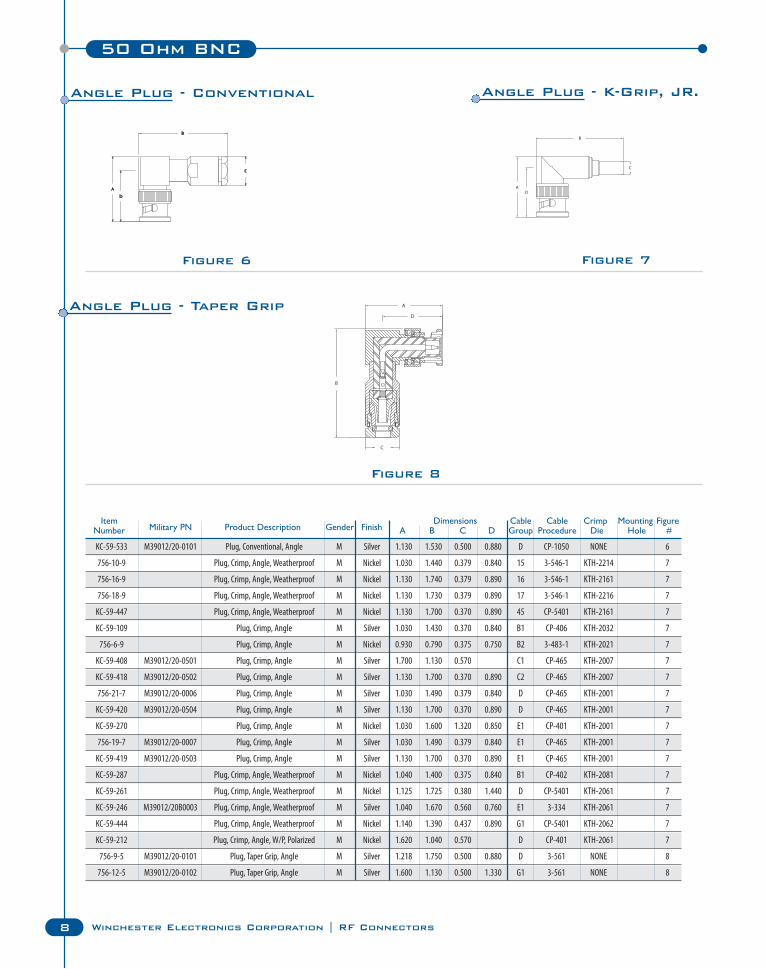
KC-59-533 M39012/20-0101 Plug, Conventional, Angle M Silver 1.130 1.530 0.500 0.880 D CP-1050 NONE 6
756-10-9 Plug, Crimp, Angle, Weatherproof M Nickel 1.030 1.440 0.379 0.840 15 3-546-1 KTH-2214 7
756-16-9 Plug, Crimp, Angle, Weatherproof M Nickel 1.130 1.740 0.379 0.890 16 3-546-1 KTH-2161 7
756-18-9 Plug, Crimp, Angle, Weatherproof M Nickel 1.130 1.730 0.379 0.890 17 3-546-1 KTH-2216 7
KC-59-447 Plug, Crimp, Angle, Weatherproof M Nickel 1.130 1.700 0.370 0.890 45 CP-5401 KTH-2161 7
KC-59-109 Plug, Crimp, Angle M Silver 1.030 1.430 0.370 0.840 B1 CP-406 KTH-2032 7
756-6-9 Plug, Crimp, Angle M Nickel 0.930 0.790 0.375 0.750 B2 3-483-1 KTH-2021 7
KC-59-408 M39012/20-0501 Plug, Crimp, Angle M Silver 1.700 1.130 0.570 C1 CP-465 KTH-2007 7
KC-59-418 M39012/20-0502 Plug, Crimp, Angle M Silver 1.130 1.700 0.370 0.890 C2 CP-465 KTH-2007 7
756-21-7 M39012/20-0006 Plug, Crimp, Angle M Silver 1.030 1.490 0.379 0.840 D CP-465 KTH-2001 7
KC-59-420 M39012/20-0504 Plug, Crimp, Angle M Silver 1.130 1.700 0.370 0.890 D CP-465 KTH-2001 7
KC-59-270 Plug, Crimp, Angle M Nickel 1.030 1.600 1.320 0.850 E1 CP-401 KTH-2001 7
756-19-7 M39012/20-0007 Plug, Crimp, Angle M Silver 1.030 1.490 0.379 0.840 E1 CP-465 KTH-2001 7
KC-59-419 M39012/20-0503 Plug, Crimp, Angle M Silver 1.130 1.700 0.370 0.890 E1 CP-465 KTH-2001 7
KC-59-287 Plug, Crimp, Angle, Weatherproof M Nickel 1.040 1.400 0.375 0.840 B1 CP-402 KTH-2081 7
KC-59-261 Plug, Crimp, Angle, Weatherproof M Nickel 1.125 1.725 0.380 1.440 D CP-5401 KTH-2061 7
KC-59-246 M39012/20B0003 Plug, Crimp, Angle, Weatherproof M Silver 1.040 1.670 0.560 0.760 E1 3-334 KTH-2061 7
KC-59-444 Plug, Crimp, Angle, Weatherproof M Nickel 1.140 1.390 0.437 0.890 G1 CP-5401 KTH-2062 7
KC-59-212 Plug, Crimp, Angle, W/P, Polarized M Nickel 1.620 1.040 0.570 D CP-401 KTH-2061 7
756-9-5 M39012/20-0101 Plug, Taper Grip, Angle M Silver 1.218 1.750 0.500 0.880 D 3-561 NONE 8
756-12-5 M39012/20-0102 Plug, Taper Grip, Angle M Silver 1.600 1.130 0.500 1.330 G1 3-561 NONE 8
Item Dimensions Cable Cable Crimp Mounting FigureNumber Military PN Product Description Gender Finish A B C D Group Procedure Die Hole #
Figure 7Figure 6
Figure 8
Angle Plug - Conventional Angle Plug - K-Grip, JR.
Angle Plug - Taper Grip
Connecting Innovation to Application®50 Ohm BNC
9
50 O
hm B
NC
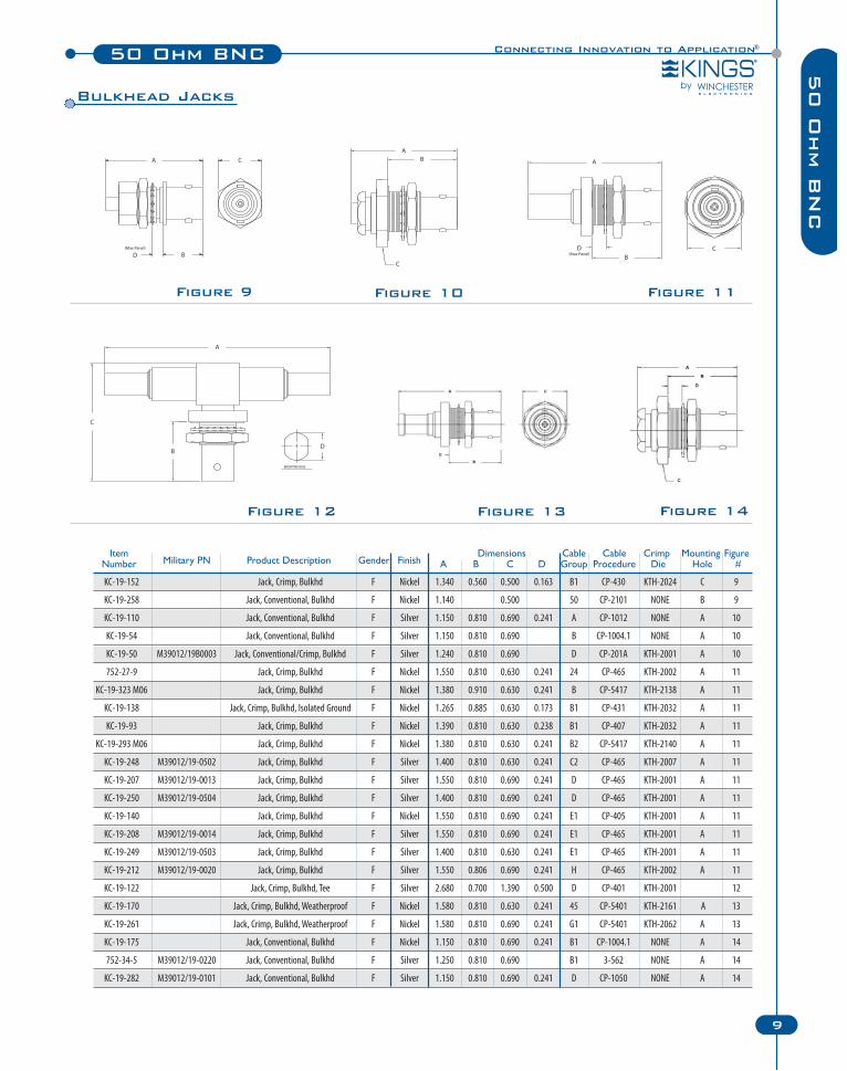
KC-19-152 Jack, Crimp, Bulkhd F Nickel 1.340 0.560 0.500 0.163 B1 CP-430 KTH-2024 C 9
KC-19-258 Jack, Conventional, Bulkhd F Nickel 1.140 0.500 50 CP-2101 NONE B 9
KC-19-110 Jack, Conventional, Bulkhd F Silver 1.150 0.810 0.690 0.241 A CP-1012 NONE A 10
KC-19-54 Jack, Conventional, Bulkhd F Silver 1.150 0.810 0.690 B CP-1004.1 NONE A 10
KC-19-50 M39012/19B0003 Jack, Conventional/Crimp, Bulkhd F Silver 1.240 0.810 0.690 D CP-201A KTH-2001 A 10
752-27-9 Jack, Crimp, Bulkhd F Nickel 1.550 0.810 0.630 0.241 24 CP-465 KTH-2002 A 11
KC-19-323 M06 Jack, Crimp, Bulkhd F Nickel 1.380 0.910 0.630 0.241 B CP-5417 KTH-2138 A 11
KC-19-138 Jack, Crimp, Bulkhd, Isolated Ground F Nickel 1.265 0.885 0.630 0.173 B1 CP-431 KTH-2032 A 11
KC-19-93 Jack, Crimp, Bulkhd F Nickel 1.390 0.810 0.630 0.238 B1 CP-407 KTH-2032 A 11
KC-19-293 M06 Jack, Crimp, Bulkhd F Nickel 1.380 0.810 0.630 0.241 B2 CP-5417 KTH-2140 A 11
KC-19-248 M39012/19-0502 Jack, Crimp, Bulkhd F Silver 1.400 0.810 0.630 0.241 C2 CP-465 KTH-2007 A 11
KC-19-207 M39012/19-0013 Jack, Crimp, Bulkhd F Silver 1.550 0.810 0.690 0.241 D CP-465 KTH-2001 A 11
KC-19-250 M39012/19-0504 Jack, Crimp, Bulkhd F Silver 1.400 0.810 0.690 0.241 D CP-465 KTH-2001 A 11
KC-19-140 Jack, Crimp, Bulkhd F Nickel 1.550 0.810 0.690 0.241 E1 CP-405 KTH-2001 A 11
KC-19-208 M39012/19-0014 Jack, Crimp, Bulkhd F Silver 1.550 0.810 0.690 0.241 E1 CP-465 KTH-2001 A 11
KC-19-249 M39012/19-0503 Jack, Crimp, Bulkhd F Silver 1.400 0.810 0.630 0.241 E1 CP-465 KTH-2001 A 11
KC-19-212 M39012/19-0020 Jack, Crimp, Bulkhd F Silver 1.550 0.806 0.690 0.241 H CP-465 KTH-2002 A 11
KC-19-122 Jack, Crimp, Bulkhd, Tee F Silver 2.680 0.700 1.390 0.500 D CP-401 KTH-2001 12
KC-19-170 Jack, Crimp, Bulkhd, Weatherproof F Nickel 1.580 0.810 0.630 0.241 45 CP-5401 KTH-2161 A 13
KC-19-261 Jack, Crimp, Bulkhd, Weatherproof F Nickel 1.580 0.810 0.690 0.241 G1 CP-5401 KTH-2062 A 13
KC-19-175 Jack, Conventional, Bulkhd F Nickel 1.150 0.810 0.690 0.241 B1 CP-1004.1 NONE A 14
752-34-5 M39012/19-0220 Jack, Conventional, Bulkhd F Silver 1.250 0.810 0.690 B1 3-562 NONE A 14
KC-19-282 M39012/19-0101 Jack, Conventional, Bulkhd F Silver 1.150 0.810 0.690 0.241 D CP-1050 NONE A 14
Item Dimensions Cable Cable Crimp Mounting FigureNumber Military PN Product Description Gender Finish A B C D Group Procedure Die Hole #
Figure 10Figure 9 Figure 11
Figure 12 Figure 13 Figure 14
Bulkhead Jacks
50 Ohm BNC
10 Winchester Electronics Corporation | RF Connectors
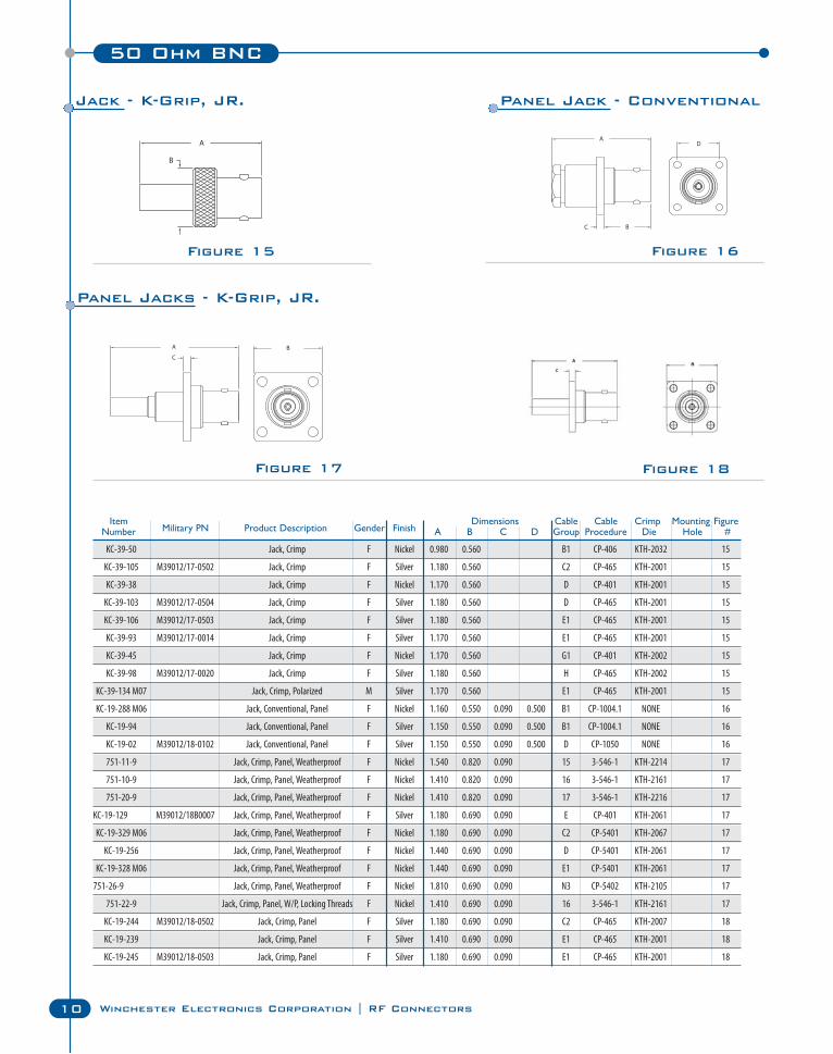
Figure 15 Figure 16
Figure 17 Figure 18
KC-39-50 Jack, Crimp F Nickel 0.980 0.560 B1 CP-406 KTH-2032 15
KC-39-105 M39012/17-0502 Jack, Crimp F Silver 1.180 0.560 C2 CP-465 KTH-2001 15
KC-39-38 Jack, Crimp F Nickel 1.170 0.560 D CP-401 KTH-2001 15
KC-39-103 M39012/17-0504 Jack, Crimp F Silver 1.180 0.560 D CP-465 KTH-2001 15
KC-39-106 M39012/17-0503 Jack, Crimp F Silver 1.180 0.560 E1 CP-465 KTH-2001 15
KC-39-93 M39012/17-0014 Jack, Crimp F Silver 1.170 0.560 E1 CP-465 KTH-2001 15
KC-39-45 Jack, Crimp F Nickel 1.170 0.560 G1 CP-401 KTH-2002 15
KC-39-98 M39012/17-0020 Jack, Crimp F Silver 1.180 0.560 H CP-465 KTH-2002 15
KC-39-134 M07 Jack, Crimp, Polarized M Silver 1.170 0.560 E1 CP-465 KTH-2001 15
KC-19-288 M06 Jack, Conventional, Panel F Nickel 1.160 0.550 0.090 0.500 B1 CP-1004.1 NONE 16
KC-19-94 Jack, Conventional, Panel F Silver 1.150 0.550 0.090 0.500 B1 CP-1004.1 NONE 16
KC-19-02 M39012/18-0102 Jack, Conventional, Panel F Silver 1.150 0.550 0.090 0.500 D CP-1050 NONE 16
751-11-9 Jack, Crimp, Panel, Weatherproof F Nickel 1.540 0.820 0.090 15 3-546-1 KTH-2214 17
751-10-9 Jack, Crimp, Panel, Weatherproof F Nickel 1.410 0.820 0.090 16 3-546-1 KTH-2161 17
751-20-9 Jack, Crimp, Panel, Weatherproof F Nickel 1.410 0.820 0.090 17 3-546-1 KTH-2216 17
KC-19-129 M39012/18B0007 Jack, Crimp, Panel, Weatherproof F Silver 1.180 0.690 0.090 E CP-401 KTH-2061 17
KC-19-329 M06 Jack, Crimp, Panel, Weatherproof F Nickel 1.180 0.690 0.090 C2 CP-5401 KTH-2067 17
KC-19-256 Jack, Crimp, Panel, Weatherproof F Nickel 1.440 0.690 0.090 D CP-5401 KTH-2061 17
KC-19-328 M06 Jack, Crimp, Panel, Weatherproof F Nickel 1.440 0.690 0.090 E1 CP-5401 KTH-2061 17
751-26-9 Jack, Crimp, Panel, Weatherproof F Nickel 1.810 0.690 0.090 N3 CP-5402 KTH-2105 17
751-22-9 Jack, Crimp, Panel, W/P, Locking Threads F Nickel 1.410 0.690 0.090 16 3-546-1 KTH-2161 17
KC-19-244 M39012/18-0502 Jack, Crimp, Panel F Silver 1.180 0.690 0.090 C2 CP-465 KTH-2007 18
KC-19-239 Jack, Crimp, Panel F Silver 1.410 0.690 0.090 E1 CP-465 KTH-2001 18
KC-19-245 M39012/18-0503 Jack, Crimp, Panel F Silver 1.180 0.690 0.090 E1 CP-465 KTH-2001 18
Item Dimensions Cable Cable Crimp Mounting FigureNumber Military PN Product Description Gender Finish A B C D Group Procedure Die Hole #
Jack - K-Grip, JR. Panel Jack - Conventional
Panel Jacks - K-Grip, JR.
Connecting Innovation to Application®50 Ohm BNC
11
50 O
hm B
NC
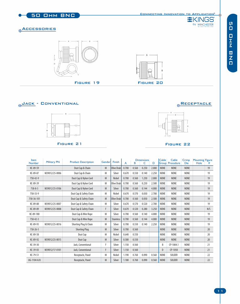
Figure 20Figure 19
Accessories
Figure 22
Receptacle
Figure 21
Jack - Conventional
KC-89-59 Dust Cap & Chain M Olive Drab 0.700 0.560 0.250 2.000 NONE NONE NONE 19
KC-89-87 M39012/25-0006 Dust Cap & Chain M Silver 0.670 0.550 0.140 2.250 NONE NONE NONE 19
758-42-9 Dust Cap & Nylon Cord M Nickel 0.700 0.560 1.250 2.000 NONE NONE NONE 19
KC-89-39 Dust Cap & Nylon Cord M Olive Drab 0.700 0.560 0.250 2.500 NONE NONE NONE 19
758-8-5 M39012/25-0106 Dust Cap & Nylon Cord M Silver 0.700 0.560 0.144 4.000 NONE NONE NONE 19
758-33-9 Dust Cap & Safety Chain M Nickel 0.670 0.570 0.030 2.700 NONE NONE NONE 19
758-36-101 Dust Cap & Safety Chain M Olive Drab 0.700 0.560 0.050 2.500 NONE NONE NONE 19
KC-89-88 M39012/25-0007 Dust Cap & Safety Chain M Silver 0.670 0.570 0.520 2.700 NONE NONE NONE 19
KC-89-89 M39012/25-0008 Dust Cap & Safety Chain F Silver 0.670 0.520 0.280 3.250 NONE NONE NONE N/S
KC-89-180 Dust Cap & Wire Rope M Silver 0.700 0.560 0.140 4.000 NONE NONE NONE 19
758-42-3 Dust Cap & Wire Rope M Stainless 0.700 0.560 0.144 4.000 NONE NONE NONE 19
KC-89-93 M39012/25-0016 Shorting Plug & Chain M Silver 0.700 0.550 0.140 2.250 NONE NONE NONE 19
758-26-5 Shorting Plug M Silver 0.700 0.560 NONE NONE NONE 20
KC-89-58 Dust Cap M Nickel 0.640 0.550 NONE NONE NONE 20
KC-89-92 M39012/25-0015 Dust Cap M Silver 0.580 0.550 NONE NONE NONE 20
KC-39-30 Jack, Conventional F Silver 1.150 0.560 B CP-1004.1 NONE 21
KC-39-03 M39012/17-0101 Jack, Conventional F Silver 1.150 0.560 D CP-1050 NONE 21
KC-79-51 Receptacle, Panel M Nickel 1.190 0.760 0.090 0.560 NONE SOLDER NONE 22
UG-1104 A/U Receptacle, Panel M Silver 1.180 0.760 0.090 0.560 NONE SOLDER NONE 22
Item Dimensions Cable Cable Crimp Mounting FigureNumber Military PN Product Description Gender Finish A B C D Group Procedure Die Hole #
50 Ohm BNC
12 Winchester Electronics Corporation | RF Connectors
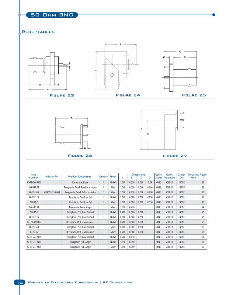
Figure 24 Figure 25Figure 23
Figure 27Figure 26
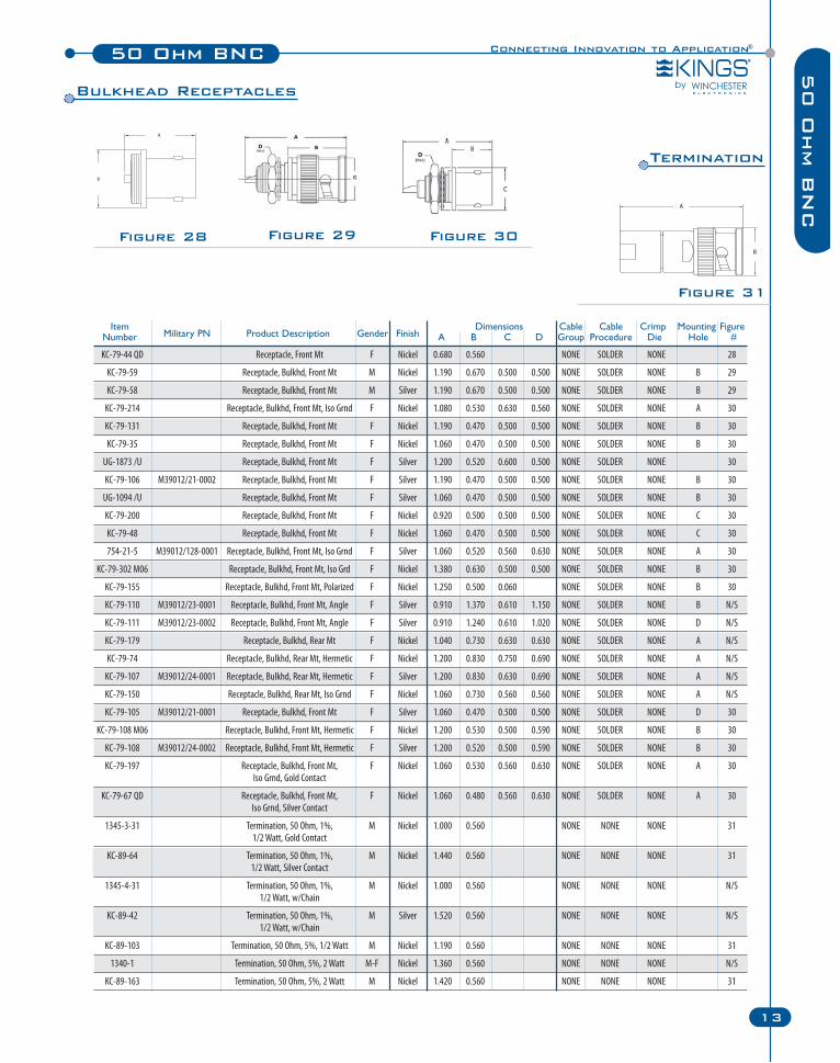
Receptacles
KC-79-260 M06 Receptacle, Panel F Nickel 1.060 0.630 0.060 0.09 NONE SOLDER NONE 23
UG-447 /U Receptacle, Panel, Rexolite Insulator F Silver 1.060 0.630 0.060 0.090 NONE SOLDER NONE 23
KC-79-109 M39012/22-0001 Receptacle, Panel, Teflon Insulator F Silver 1.060 0.630 0.060 0.090 NONE SOLDER NONE 23
KC-79-125 Receptacle, Panel, Iso Grd F Nickel 1.060 0.600 0.060 0.090 NONE SOLDER NONE 23
757-29-5 Receptacle, Panel, Iso Grd F Silver 1.060 0.600 0.060 0.120 NONE SOLDER NONE 23
UG-535 /U Receptacle, Panel, Angle F Silver 1.090 0.720 NONE SOLDER NONE 24
757-15-9 Receptacle, PCB, Gold Contact F Nickel 0.780 0.560 0.090 NONE SOLDER NONE 25
KC-79-215 Receptacle, PCB, Gold Contact F Nickel 0.900 0.560 0.090 NONE SOLDER NONE 25
KC-79-07 M06 Receptacle, PCB, Silver Contact F Nickel 0.780 0.560 0.090 NONE SOLDER NONE 25
KC-79-168 Receptacle, PCB, Gold Contact F Silver 0.780 0.560 0.090 NONE SOLDER NONE 25
KC-79-07 Receptacle, PCB, Silver Contact F Silver 0.780 0.560 0.090 NONE SOLDER NONE 25
KC-79-274 M06 Receptacle, PCB, Gold Contact F Nickel 0.780 0.130 NONE SOLDER NONE 26
KC-79-237 M06 Receptacle, PCB, Angle F Nickel 1.340 0.990 NONE SOLDER NONE 27
KC-79-237 M07 Receptacle, PCB, Angle F Silver 1.340 0.990 NONE SOLDER NONE 27
Item Dimensions Cable Cable Crimp Mounting FigureNumber Military PN Product Description Gender Finish A B C D Group Procedure Die Hole #
13
50 O
hm B
NC
50 Ohm BNC
13
Connecting Innovation to Application®
KC-79-44 QD Receptacle, Front Mt F Nickel 0.680 0.560 NONE SOLDER NONE 28
KC-79-59 Receptacle, Bulkhd, Front Mt M Nickel 1.190 0.670 0.500 0.500 NONE SOLDER NONE B 29
KC-79-58 Receptacle, Bulkhd, Front Mt M Silver 1.190 0.670 0.500 0.500 NONE SOLDER NONE B 29
KC-79-214 Receptacle, Bulkhd, Front Mt, Iso Grnd F Nickel 1.080 0.530 0.630 0.560 NONE SOLDER NONE A 30
KC-79-131 Receptacle, Bulkhd, Front Mt F Nickel 1.190 0.470 0.500 0.500 NONE SOLDER NONE B 30
KC-79-35 Receptacle, Bulkhd, Front Mt F Nickel 1.060 0.470 0.500 0.500 NONE SOLDER NONE B 30
UG-1873 /U Receptacle, Bulkhd, Front Mt F Silver 1.200 0.520 0.600 0.500 NONE SOLDER NONE 30
KC-79-106 M39012/21-0002 Receptacle, Bulkhd, Front Mt F Silver 1.190 0.470 0.500 0.500 NONE SOLDER NONE B 30
UG-1094 /U Receptacle, Bulkhd, Front Mt F Silver 1.060 0.470 0.500 0.500 NONE SOLDER NONE B 30
KC-79-200 Receptacle, Bulkhd, Front Mt F Nickel 0.920 0.500 0.500 0.500 NONE SOLDER NONE C 30
KC-79-48 Receptacle, Bulkhd, Front Mt F Nickel 1.060 0.470 0.500 0.500 NONE SOLDER NONE C 30
754-21-5 M39012/128-0001 Receptacle, Bulkhd, Front Mt, Iso Grnd F Silver 1.060 0.520 0.560 0.630 NONE SOLDER NONE A 30
KC-79-302 M06 Receptacle, Bulkhd, Front Mt, Iso Grd F Nickel 1.380 0.630 0.500 0.500 NONE SOLDER NONE B 30
KC-79-155 Receptacle, Bulkhd, Front Mt, Polarized F Nickel 1.250 0.500 0.060 NONE SOLDER NONE B 30
KC-79-110 M39012/23-0001 Receptacle, Bulkhd, Front Mt, Angle F Silver 0.910 1.370 0.610 1.150 NONE SOLDER NONE B N/S
KC-79-111 M39012/23-0002 Receptacle, Bulkhd, Front Mt, Angle F Silver 0.910 1.240 0.610 1.020 NONE SOLDER NONE D N/S
KC-79-179 Receptacle, Bulkhd, Rear Mt F Nickel 1.040 0.730 0.630 0.630 NONE SOLDER NONE A N/S
KC-79-74 Receptacle, Bulkhd, Rear Mt, Hermetic F Nickel 1.200 0.830 0.750 0.690 NONE SOLDER NONE A N/S
KC-79-107 M39012/24-0001 Receptacle, Bulkhd, Rear Mt, Hermetic F Silver 1.200 0.830 0.630 0.690 NONE SOLDER NONE A N/S
KC-79-150 Receptacle, Bulkhd, Rear Mt, Iso Grnd F Nickel 1.060 0.730 0.560 0.560 NONE SOLDER NONE A N/S
KC-79-105 M39012/21-0001 Receptacle, Bulkhd, Front Mt F Silver 1.060 0.470 0.500 0.500 NONE SOLDER NONE D 30
KC-79-108 M06 Receptacle, Bulkhd, Front Mt, Hermetic F Nickel 1.200 0.530 0.500 0.590 NONE SOLDER NONE B 30
KC-79-108 M39012/24-0002 Receptacle, Bulkhd, Front Mt, Hermetic F Silver 1.200 0.520 0.500 0.590 NONE SOLDER NONE B 30
KC-79-197 Receptacle, Bulkhd, Front Mt, F Nickel 1.060 0.530 0.560 0.630 NONE SOLDER NONE A 30Iso Grnd, Gold Contact
KC-79-67 QD Receptacle, Bulkhd, Front Mt, F Nickel 1.060 0.480 0.560 0.630 NONE SOLDER NONE A 30Iso Grnd, Silver Contact
1345-3-31 Termination, 50 Ohm, 1%, M Nickel 1.000 0.560 NONE NONE NONE 31 1/2 Watt, Gold Contact
KC-89-64 Termination, 50 Ohm, 1%, M Nickel 1.440 0.560 NONE NONE NONE 31 1/2 Watt, Silver Contact
1345-4-31 Termination, 50 Ohm, 1%, M Nickel 1.000 0.560 NONE NONE NONE N/S 1/2 Watt, w/Chain
KC-89-42 Termination, 50 Ohm, 1%, M Silver 1.520 0.560 NONE NONE NONE N/S 1/2 Watt, w/Chain
KC-89-103 Termination, 50 Ohm, 5%, 1/2 Watt M Nickel 1.190 0.560 NONE NONE NONE 31
1340-1 Termination, 50 Ohm, 5%, 2 Watt M-F Nickel 1.360 0.560 NONE NONE NONE N/S
KC-89-163 Termination, 50 Ohm, 5%, 2 Watt M Nickel 1.420 0.560 NONE NONE NONE 31
Item Dimensions Cable Cable Crimp Mounting FigureNumber Military PN Product Description Gender Finish A B C D Group Procedure Die Hole #
Figure 28 Figure 30Figure 29
Figure 31
Bulkhead Receptacles
Termination
14 Winchester Electronics Corporation | RF Connectors 14
50 Ohm BNC
50 O
hm B
NC
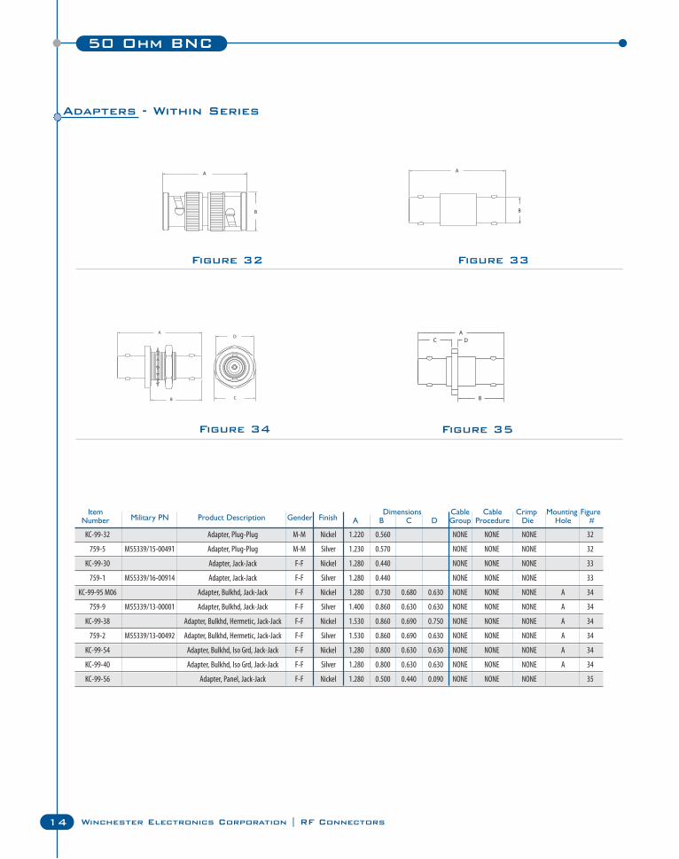
Figure 32
Figure 34
Figure 33
Figure 35
Adapters - Within Series
KC-99-32 Adapter, Plug-Plug M-M Nickel 1.220 0.560 NONE NONE NONE 32
759-5 M55339/15-00491 Adapter, Plug-Plug M-M Silver 1.230 0.570 NONE NONE NONE 32
KC-99-30 Adapter, Jack-Jack F-F Nickel 1.280 0.440 NONE NONE NONE 33
759-1 M55339/16-00914 Adapter, Jack-Jack F-F Silver 1.280 0.440 NONE NONE NONE 33
KC-99-95 M06 Adapter, Bulkhd, Jack-Jack F-F Nickel 1.280 0.730 0.680 0.630 NONE NONE NONE A 34
759-9 M55339/13-00001 Adapter, Bulkhd, Jack-Jack F-F Silver 1.400 0.860 0.630 0.630 NONE NONE NONE A 34
KC-99-38 Adapter, Bulkhd, Hermetic, Jack-Jack F-F Nickel 1.530 0.860 0.690 0.750 NONE NONE NONE A 34
759-2 M55339/13-00492 Adapter, Bulkhd, Hermetic, Jack-Jack F-F Silver 1.530 0.860 0.690 0.630 NONE NONE NONE A 34
KC-99-54 Adapter, Bulkhd, Iso Grd, Jack-Jack F-F Nickel 1.280 0.800 0.630 0.630 NONE NONE NONE A 34
KC-99-40 Adapter, Bulkhd, Iso Grd, Jack-Jack F-F Silver 1.280 0.800 0.630 0.630 NONE NONE NONE A 34
KC-99-56 Adapter, Panel, Jack-Jack F-F Nickel 1.280 0.500 0.440 0.090 NONE NONE NONE 35
Item Dimensions Cable Cable Crimp Mounting FigureNumber Military PN Product Description Gender Finish A B C D Group Procedure Die Hole #
50 Ohm BNC
15
50 O
hm B
NC
Connecting Innovation to Application®
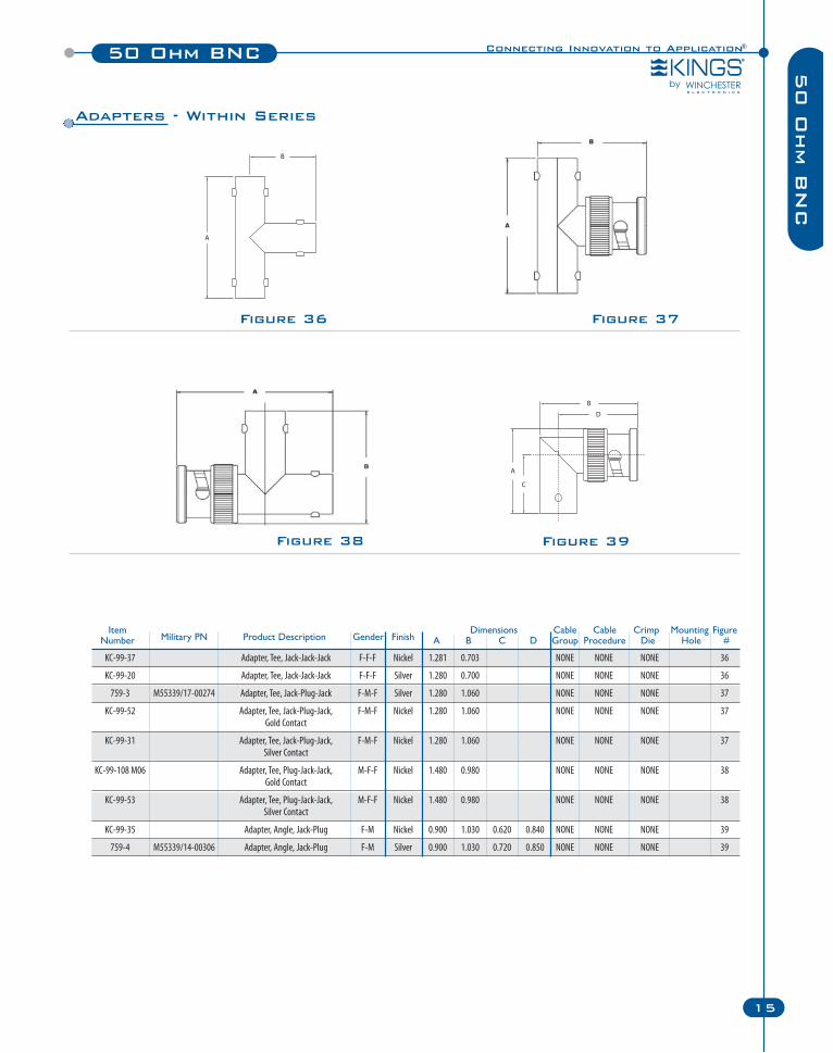
KC-99-37 Adapter, Tee, Jack-Jack-Jack F-F-F Nickel 1.281 0.703 NONE NONE NONE 36
KC-99-20 Adapter, Tee, Jack-Jack-Jack F-F-F Silver 1.280 0.700 NONE NONE NONE 36
759-3 M55339/17-00274 Adapter, Tee, Jack-Plug-Jack F-M-F Silver 1.280 1.060 NONE NONE NONE 37
KC-99-52 Adapter, Tee, Jack-Plug-Jack, F-M-F Nickel 1.280 1.060 NONE NONE NONE 37Gold Contact
KC-99-31 Adapter, Tee, Jack-Plug-Jack, F-M-F Nickel 1.280 1.060 NONE NONE NONE 37Silver Contact
KC-99-108 M06 Adapter, Tee, Plug-Jack-Jack, M-F-F Nickel 1.480 0.980 NONE NONE NONE 38Gold Contact
KC-99-53 Adapter, Tee, Plug-Jack-Jack, M-F-F Nickel 1.480 0.980 NONE NONE NONE 38Silver Contact
KC-99-35 Adapter, Angle, Jack-Plug F-M Nickel 0.900 1.030 0.620 0.840 NONE NONE NONE 39
759-4 M55339/14-00306 Adapter, Angle, Jack-Plug F-M Silver 0.900 1.030 0.720 0.850 NONE NONE NONE 39
Item Dimensions Cable Cable Crimp Mounting FigureNumber Military PN Product Description Gender Finish A B C D Group Procedure Die Hole #
Figure 36
Figure 39
Adapters - Within Series
Figure 37
Figure 38
16 Winchester Electronics Corporation | RF Connectors
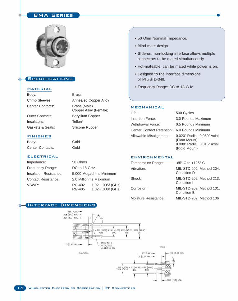
BMA Series
Specifications
MATERIAL
Body: BrassCrimp Sleeves: Annealed Copper AlloyCenter Contacts: Brass (Male)
Copper Alloy (Female)Outer Contacts: Beryllium CopperInsulators: Teflon®
Gaskets & Seals: Silicone Rubber
FINISHES
Body: GoldCenter Contacts: Gold
ELECTRICAL
Impedance: 50 OhmsFrequency Range: DC to 18 GHzInsulation Resistance: 5,000 Megaohms MinimumContact Resistance: 2.0 Milliohms MaximumVSWR: RG-402 1.02+ .005f (GHz)
RG-405 1.02+ .008f (GHz)
• 50 Ohm Nominal Impedance.
• Blind mate design.
• Slide-on, non-locking interface allows multipleconnectors to be mated simultaneously.
• Hot-mateable, can be mated while power is on.
• Designed to the interface dimensions of MIL-STD-348.
• Frequency Range: DC to 18 GHz
MECHANICAL
Life: 500 CyclesInsertion Force: 3.0 Pounds MaximumWithdrawal Force: 0.5 Pounds MinimumCenter Contact Retention: 6.0 Pounds MinimumAllowable Misalignment: 0.020” Radial, 0.060” Axial
(Float Mount)0.008” Radial, 0.015” Axial (Rigid Mount)
ENVIRONMENTAL
Temperature Range: -65° C to +125° CVibration: MIL-STD-202, Method 204,
Condition DShock: MIL-STD-202, Method 213,
Condition ICorrosion: MIL-STD-202, Method 101,
Condition BMoisture Resistance: MIL-STD-202, Method 106
Interface Dimensions
Connecting Innovation to Application®BMA Series
17
BM
A S
erie
s
Figure 3Figure 2Figure 1
Figure 8Figure 6 Figure 7
Figure 4 Figure 5
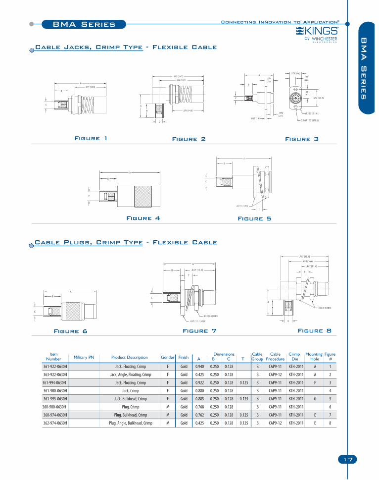
Item Dimensions Cable Cable Crimp Mounting FigureNumber Military PN Product Description Gender Finish A B C T Group Procedure Die Hole #
361-922-0630H Jack, Floating, Crimp F Gold 0.940 0.250 0.128 B CAP9-11 KTH-2011 A 1
363-922-0630H Jack, Angle, Floating, Crimp F Gold 0.425 0.250 0.128 B CAP9-12 KTH-2011 A 2
361-994-0630H Jack, Floating, Crimp F Gold 0.922 0.250 0.128 0.125 B CAP9-11 KTH-2011 F 3
361-900-0630H Jack, Crimp F Gold 0.880 0.250 0.128 B CAP9-11 KTH-2011 4
361-995-0630H Jack, Bulkhead, Crimp F Gold 0.885 0.250 0.128 0.125 B CAP9-11 KTH-2011 G 5
360-900-0630H Plug, Crimp M Gold 0.768 0.250 0.128 B CAP9-11 KTH-2011 6
360-974-0630H Plug, Bulkhead, Crimp M Gold 0.762 0.250 0.128 0.125 B CAP9-11 KTH-2011 E 7
362-974-0630H Plug, Angle, Bulkhead, Crimp M Gold 0.425 0.250 0.128 0.125 B CAP9-12 KTH-2011 E 8
Cable Plugs, Crimp Type - Flexible Cable
Cable Jacks, Crimp Type - Flexible Cable
BMA Series
18 Winchester Electronics Corporation | RF Connectors
Figure 16Figure 14
Figure 13
Figure 10
Figure 12
Figure 15
Figure 11Figure 9
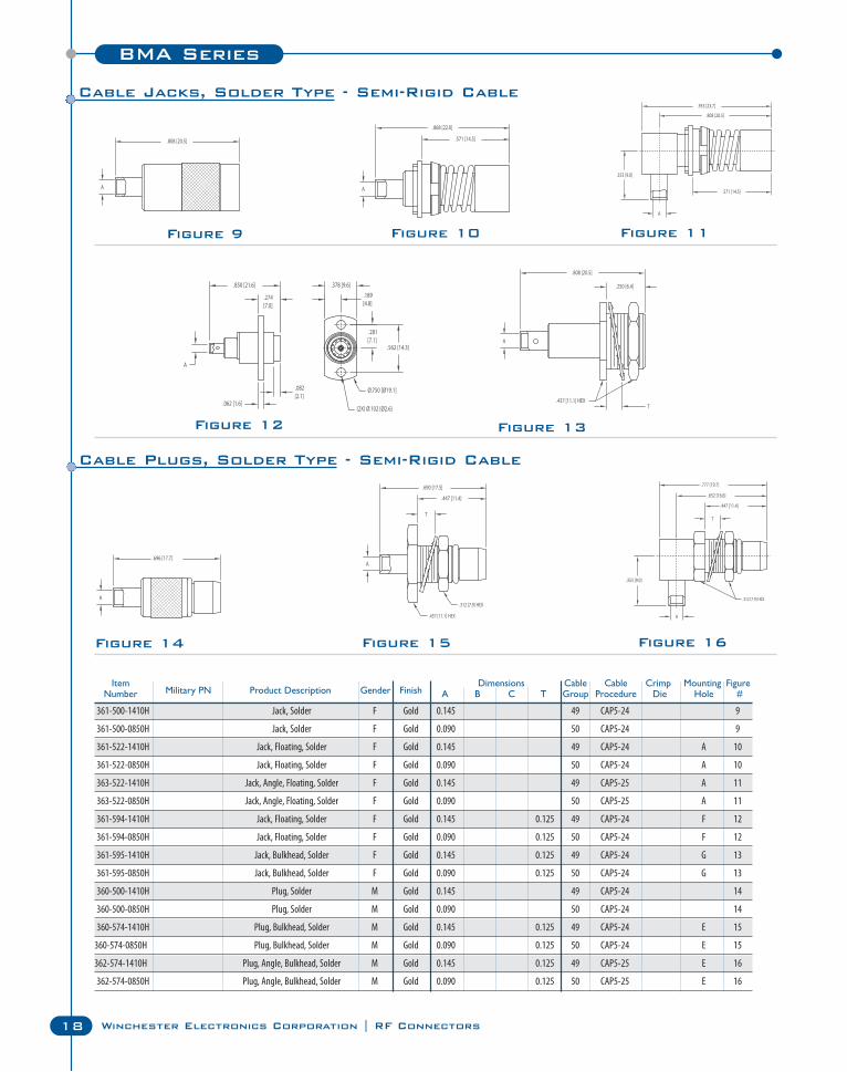
Item Dimensions Cable Cable Crimp Mounting FigureNumber Military PN Product Description Gender Finish A B C T Group Procedure Die Hole #
361-500-1410H Jack, Solder F Gold 0.145 49 CAP5-24 9
361-500-0850H Jack, Solder F Gold 0.090 50 CAP5-24 9
361-522-1410H Jack, Floating, Solder F Gold 0.145 49 CAP5-24 A 10
361-522-0850H Jack, Floating, Solder F Gold 0.090 50 CAP5-24 A 10
363-522-1410H Jack, Angle, Floating, Solder F Gold 0.145 49 CAP5-25 A 11
363-522-0850H Jack, Angle, Floating, Solder F Gold 0.090 50 CAP5-25 A 11
361-594-1410H Jack, Floating, Solder F Gold 0.145 0.125 49 CAP5-24 F 12
361-594-0850H Jack, Floating, Solder F Gold 0.090 0.125 50 CAP5-24 F 12
361-595-1410H Jack, Bulkhead, Solder F Gold 0.145 0.125 49 CAP5-24 G 13
361-595-0850H Jack, Bulkhead, Solder F Gold 0.090 0.125 50 CAP5-24 G 13
360-500-1410H Plug, Solder M Gold 0.145 49 CAP5-24 14
360-500-0850H Plug, Solder M Gold 0.090 50 CAP5-24 14
360-574-1410H Plug, Bulkhead, Solder M Gold 0.145 0.125 49 CAP5-24 E 15
360-574-0850H Plug, Bulkhead, Solder M Gold 0.090 0.125 50 CAP5-24 E 15
362-574-1410H Plug, Angle, Bulkhead, Solder M Gold 0.145 0.125 49 CAP5-25 E 16
362-574-0850H Plug, Angle, Bulkhead, Solder M Gold 0.090 0.125 50 CAP5-25 E 16
Cable Jacks, Solder Type - Semi-Rigid Cable
Cable Plugs, Solder Type - Semi-Rigid Cable
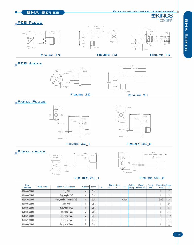
Figure 23_2
Figure 20
Figure 23_1
Figure 21
Connecting Innovation to Application®BMA Series
19
BM
A S
erie
s
Figure 18Figure 17
Figure 22_1 Figure 22_2
Figure 19
Item Dimensions Cable Cable Crimp Mounting FigureNumber Military PN Product Description Gender Finish A B C T Group Procedure Die Hole #
360-060-0040H Plug, PWB M Gold B 17
362-060-0040H Plug, Angle, PWB M Gold B 18
362-074-6040H Plug, Angle, Bulkhead, PWB M Gold 0.125 B & E 19
361-060-0040H Jack, PWB F Gold B 20
363-060-0040H Jack, Angle, PWB F Gold B 21
360-066-0040H Receptacle, Panel M Gold D 22_1
360-065-0040H Receptacle, Panel M Gold C 22_2
361-065-0040H Receptacle, Panel F Gold C 23_1
361-066-0040H Receptacle, Panel F Gold D 23_2
PCB Plugs
PCB Jacks
Panel Plugs
Panel Jacks
C Series
20 Winchester Electronics Corporation | RF Connectors
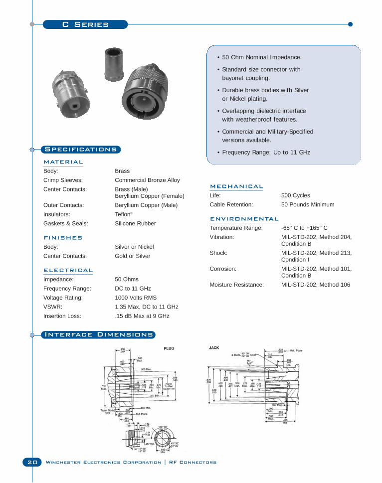
Specifications
MATERIAL
Body: BrassCrimp Sleeves: Commercial Bronze AlloyCenter Contacts: Brass (Male)
Beryllium Copper (Female)Outer Contacts: Beryllium Copper (Male)Insulators: Teflon®
Gaskets & Seals: Silicone Rubber
FINISHES
Body: Silver or NickelCenter Contacts: Gold or Silver
ELECTRICAL
Impedance: 50 OhmsFrequency Range: DC to 11 GHzVoltage Rating: 1000 Volts RMSVSWR: 1.35 Max, DC to 11 GHzInsertion Loss: .15 dB Max at 9 GHz
• 50 Ohm Nominal Impedance.
• Standard size connector with bayonet coupling.
• Durable brass bodies with Silver or Nickel plating.
• Overlapping dielectric interface with weatherproof features.
• Commercial and Military-Specifiedversions available.
• Frequency Range: Up to 11 GHz
MECHANICAL
Life: 500 CyclesCable Retention: 50 Pounds Minimum
ENVIRONMENTAL
Temperature Range: -65° C to +165° CVibration: MIL-STD-202, Method 204,
Condition BShock: MIL-STD-202, Method 213,
Condition ICorrosion: MIL-STD-202, Method 101,
Condition BMoisture Resistance: MIL-STD-202, Method 106
Interface Dimensions
Connecting Innovation to Application®C Series
21
C S
erie
s
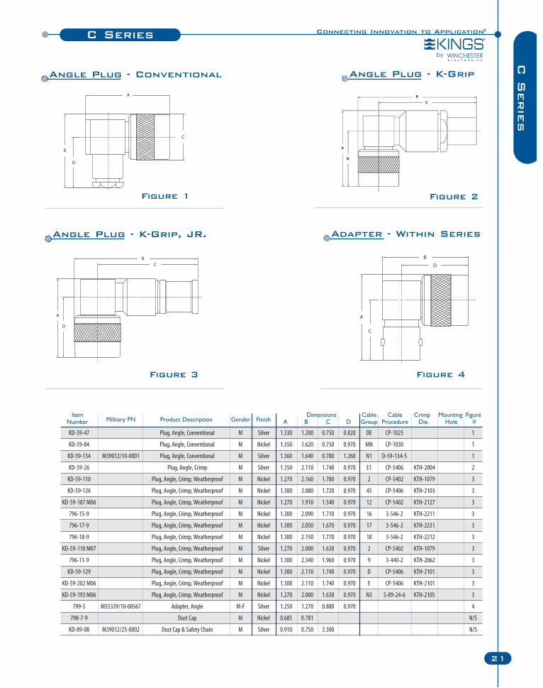
Figure 1 Figure 2
Figure 3 Figure 4
Item Dimensions Cable Cable Crimp Mounting FigureNumber Military PN Product Description Gender Finish A B C D Group Procedure Die Hole #
KD-59-47 Plug, Angle, Conventional M Silver 1.330 1.200 0.750 0.820 DE CP-1025 1
KD-59-84 Plug, Angle, Conventional M Nickel 1.350 1.620 0.750 0.970 MN CP-1030 1
KD-59-134 M39012/10-0001 Plug, Angle, Conventional M Silver 1.360 1.640 0.780 1.260 N1 D-59-134-5 1
KD-59-26 Plug, Angle, Crimp M Silver 1.350 2.110 1.740 0.970 E1 CP-5406 KTH-2004 2
KD-59-110 Plug, Angle, Crimp, Weatherproof M Nickel 1.270 2.160 1.780 0.970 2 CP-5402 KTH-1079 3
KD-59-126 Plug, Angle, Crimp, Weatherproof M Nickel 1.300 2.080 1.720 0.970 45 CP-5406 KTH-2103 3
KD-59-187 M06 Plug, Angle, Crimp, Weatherproof M Nickel 1.270 1.910 1.540 0.970 12 CP-5402 KTH-2127 3
796-15-9 Plug, Angle, Crimp, Weatherproof M Nickel 1.300 2.090 1.710 0.970 16 3-546-2 KTH-2211 3
796-17-9 Plug, Angle, Crimp, Weatherproof M Nickel 1.300 2.050 1.670 0.970 17 3-546-2 KTH-2231 3
796-18-9 Plug, Angle, Crimp, Weatherproof M Nickel 1.300 2.150 1.770 0.970 18 3-546-2 KTH-2212 3
KD-59-110 M07 Plug, Angle, Crimp, Weatherproof M Silver 1.270 2.000 1.630 0.970 2 CP-5402 KTH-1079 3
796-11-9 Plug, Angle, Crimp, Weatherproof M Nickel 1.300 2.340 1.960 0.970 9 3-440-2 KTH-2062 3
KD-59-129 Plug, Angle, Crimp, Weatherproof M Nickel 1.300 2.110 1.740 0.970 D CP-5406 KTH-2101 3
KD-59-202 M06 Plug, Angle, Crimp, Weatherproof M Nickel 1.300 2.110 1.740 0.970 E CP-5406 KTH-2101 3
KD-59-193 M06 Plug, Angle, Crimp, Weatherproof M Nickel 1.270 2.000 1.630 0.970 N3 S-89-24-6 KTH-2105 3
799-5 M55339/10-00567 Adapter, Angle M-F Silver 1.250 1.270 0.880 0.970 4
798-7-9 Dust Cap M Nickel 0.685 0.781 N/S
KD-89-08 M39012/25-0002 Dust Cap & Safety Chain M Silver 0.910 0.750 3.500 N/S
Angle Plug - Conventional Angle Plug - K-Grip
Angle Plug - K-Grip, JR. Adapter - Within Series
C Series
22 Winchester Electronics Corporation | RF Connectors
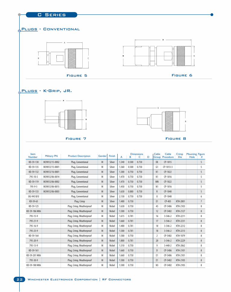
KD-59-130 M39012/15-0002 Plug, Conventional M Silver 1.340 0.500 0.750 DE CP-1015 5
KD-59-135 M39012/15-0001 Plug, Conventional M Silver 1.360 0.500 0.750 G1 CP-1013-3 5
KD-59-132 M39012/16-0001 Plug, Conventional M Silver 1.300 0.750 0.750 K1 CP-1022 5
795-10-5 M39012/06-0014 Plug, Conventional M Silver 1.470 0.750 0.750 K1 CP-1016 5
KD-59-119 M39012/06-0002 Plug, Conventional M Silver 1.470 0.750 0.750 MN CP-1022 5
795-9-5 M39012/06-0015 Plug, Conventional M Silver 1.450 0.750 0.750 N1 CP-1016 5
KD-59-133 M39012/06-0003 Plug, Conventional M Silver 1.630 0.880 0.750 R CP-1040 5
UG-943 B/U Plug, Conventional M Silver 2.130 0.750 0.750 U CP-1040 6
KD-59-63 Plug, Crimp M Silver 1.400 0.750 E1 CP-403 KTH-2001 7
KD-59-125 Plug, Crimp, Weatherproof M Nickel 1.630 0.750 45 CP-5406 KTH-2103 8
KD-59-186 M06 Plug, Crimp, Weatherproof M Nickel 1.500 0.750 12 CP-5402 KTH-2127 8
795-15-9 Plug, Crimp, Weatherproof M Nickel 1.615 0.781 16 3-546-2 KTH-2211 8
795-21-9 Plug, Crimp, Weatherproof M Nickel 1.660 0.781 17 3-546-2 KTH-2231 8
795-16-9 Plug, Crimp, Weatherproof M Nickel 1.400 0.781 18 3-546-2 KTH-2212 8
795-23-9 Plug, Crimp, Weatherproof M Nickel 1.500 0.781 18 3-546-2 KTH-2213 8
KD-59-164 Plug, Crimp, Weatherproof M Nickel 1.500 0.750 2 CP-5402 KTH-1079 8
795-20-9 Plug, Crimp, Weatherproof M Nickel 1.800 0.781 20 3-546-2 KTH-2229 8
795-13-9 Plug, Crimp, Weatherproof M Nickel 1.310 0.750 9 3-440-2 KTH-2062 8
KD-59-161 Plug, Crimp, Weatherproof M Nickel 1.660 0.750 D CP-5406 KTH-2101 8
KD-59-201 M06 Plug, Crimp, Weatherproof M Nickel 1.660 0.750 E1 CP-5406 KTH-2101 8
795-30-9 Plug, Crimp, Weatherproof M Nickel 1.500 0.750 E1 CP-5402 KTH-2105 8
KD-59-180 M06 Plug, Crimp, Weatherproof M Nickel 1.500 0.750 N3 CP-5402 KTH-2105 8
Figure 6Figure 5
Figure 7 Figure 8
Item Dimensions Cable Cable Crimp Mounting FigureNumber Military PN Product Description Gender Finish A B C D Group Procedure Die Hole #
Plugs - Conventional
Plugs - K-Grip, JR.
Connecting Innovation to Application®C Series
23
C S
erie
s
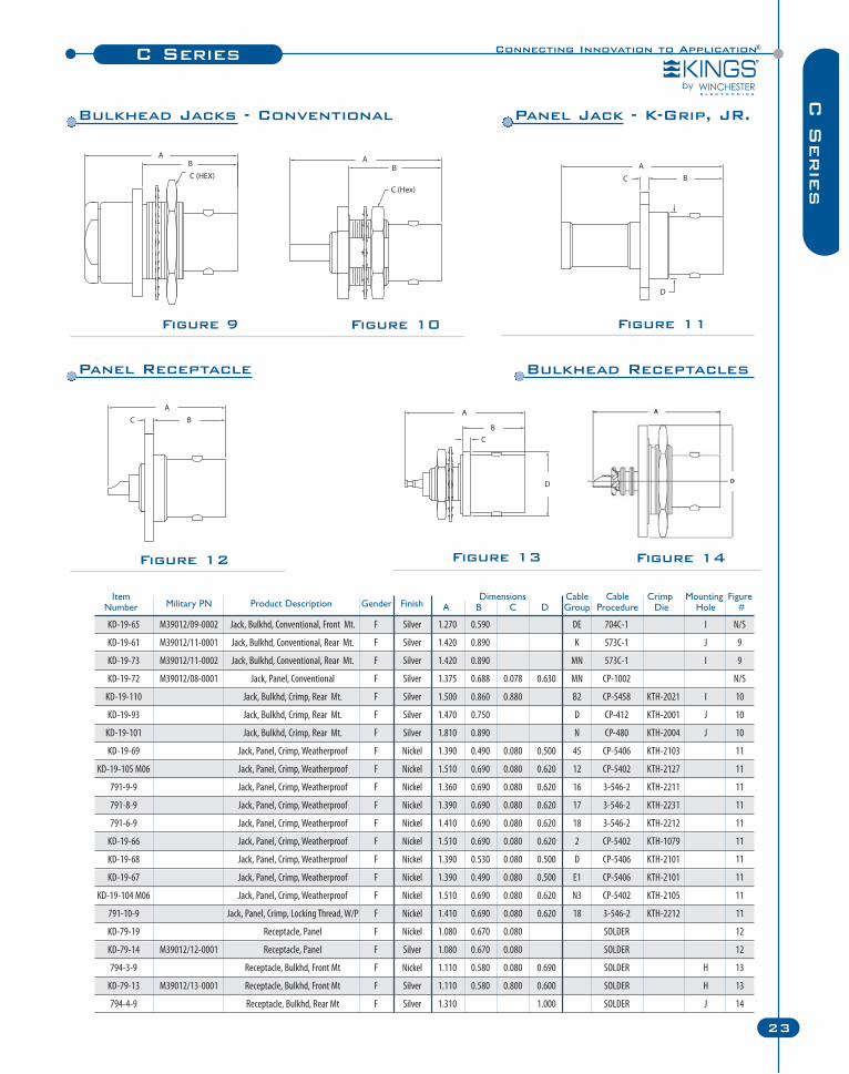
Figure 9 Figure 10 Figure 11
Figure 12 Figure 13 Figure 14
KD-19-65 M39012/09-0002 Jack, Bulkhd, Conventional, Front Mt. F Silver 1.270 0.590 DE 704C-1 I N/S
KD-19-61 M39012/11-0001 Jack, Bulkhd, Conventional, Rear Mt. F Silver 1.420 0.890 K 573C-1 J 9
KD-19-73 M39012/11-0002 Jack, Bulkhd, Conventional, Rear Mt. F Silver 1.420 0.890 MN 573C-1 I 9
KD-19-72 M39012/08-0001 Jack, Panel, Conventional F Silver 1.375 0.688 0.078 0.630 MN CP-1002 N/S
KD-19-110 Jack, Bulkhd, Crimp, Rear Mt. F Silver 1.500 0.860 0.880 B2 CP-5458 KTH-2021 I 10
KD-19-93 Jack, Bulkhd, Crimp, Rear Mt. F Silver 1.470 0.750 D CP-412 KTH-2001 J 10
KD-19-101 Jack, Bulkhd, Crimp, Rear Mt. F Silver 1.810 0.890 N CP-480 KTH-2004 J 10
KD-19-69 Jack, Panel, Crimp, Weatherproof F Nickel 1.390 0.490 0.080 0.500 45 CP-5406 KTH-2103 11
KD-19-105 M06 Jack, Panel, Crimp, Weatherproof F Nickel 1.510 0.690 0.080 0.620 12 CP-5402 KTH-2127 11
791-9-9 Jack, Panel, Crimp, Weatherproof F Nickel 1.360 0.690 0.080 0.620 16 3-546-2 KTH-2211 11
791-8-9 Jack, Panel, Crimp, Weatherproof F Nickel 1.390 0.690 0.080 0.620 17 3-546-2 KTH-2231 11
791-6-9 Jack, Panel, Crimp, Weatherproof F Nickel 1.410 0.690 0.080 0.620 18 3-546-2 KTH-2212 11
KD-19-66 Jack, Panel, Crimp, Weatherproof F Nickel 1.510 0.690 0.080 0.620 2 CP-5402 KTH-1079 11
KD-19-68 Jack, Panel, Crimp, Weatherproof F Nickel 1.390 0.530 0.080 0.500 D CP-5406 KTH-2101 11
KD-19-67 Jack, Panel, Crimp, Weatherproof F Nickel 1.390 0.490 0.080 0.500 E1 CP-5406 KTH-2101 11
KD-19-104 M06 Jack, Panel, Crimp, Weatherproof F Nickel 1.510 0.690 0.080 0.620 N3 CP-5402 KTH-2105 11
791-10-9 Jack, Panel, Crimp, Locking Thread, W/P F Nickel 1.410 0.690 0.080 0.620 18 3-546-2 KTH-2212 11
KD-79-19 Receptacle, Panel F Nickel 1.080 0.670 0.080 SOLDER 12
KD-79-14 M39012/12-0001 Receptacle, Panel F Silver 1.080 0.670 0.080 SOLDER 12
794-3-9 Receptacle, Bulkhd, Front Mt F Nickel 1.110 0.580 0.080 0.690 SOLDER H 13
KD-79-13 M39012/13-0001 Receptacle, Bulkhd, Front Mt F Silver 1.110 0.580 0.800 0.600 SOLDER H 13
794-4-9 Receptacle, Bulkhd, Rear Mt F Silver 1.310 1.000 SOLDER J 14
Item Dimensions Cable Cable Crimp Mounting FigureNumber Military PN Product Description Gender Finish A B C D Group Procedure Die Hole #
Panel Jack - K-Grip, JR.Bulkhead Jacks - Conventional
Panel Receptacle Bulkhead Receptacles
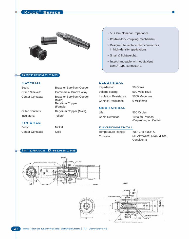
K-Loc® Series
24 Winchester Electronics Corporation | RF Connectors
Specifications
MATERIAL
Body: Brass or Beryllium CopperCrimp Sleeves: Commercial Bronze AlloyCenter Contacts: Brass or Beryllium Copper
(Male)Beryllium Copper(Female)
Outer Contacts: Beryllium Copper (Male)Insulators: Teflon®
FINISHES
Body: NickelCenter Contacts: Gold
• 50 Ohm Nominal Impedance.
• Positive-lock coupling mechanism.
• Designed to replace BNC connectors in high-density applications.
• Small & lightweight.
• Interchangeable with equivalent Lemo® type connectors.
ELECTRICAL
Impedance: 50 OhmsVoltage Rating: 500 Volts RMSInsulation Resistance: 5000 MegohmsContact Resistance: 6 Milliohms
MECHANICAL
Life: 500 CyclesCable Retention: 10 to 40 Pounds
(Depending on Cable)
ENVIRONMENTAL
Temperature Range: -65° C to +165° CCorrosion: MIL-STD-202, Method 101,
Condition B
Interface Dimensions
Connecting Innovation to Application®
25
K-L
oc
®S
erie
s
Figure 4
Figure 6
Figure 1
K-Loc® Series
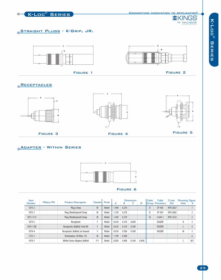
Item Dimensions Cable Cable Crimp Mounting FigureNumber Military PN Product Description Gender Finish A B C D Group Procedure Die Hole #
1075-2 Plug, Crimp M Nickel 1.440 0.270 D CP-458 KTH-2027 1
1075-1 Plug, Weatherproof Crimp M Nickel 1.370 0.270 B CP-459 KTH-2082 2
1075-13-9 Plug, Weatherproof Crimp M Nickel 1.430 0.270 16 3-644-1 KTH-2232 2
1074-5 Receptacle F Nickel 0.610 0.310 0.040 SOLDER K 3
1074-1 QD Receptacle, Bulkhd, Front Mt F Nickel 0.610 0.310 0.340 SOLDER L 4
1074-4 Receptacle, Bulkhd, Iso Ground F Nickel 0.610 0.500 0.500 SOLDER M 5
1725-1 Termination, 50 Ohm, 1% M Nickel 1.190 0.280 6
1079-7 Within Series Adapter, Bulkhd F-F Nickel 0.820 0.400 0.340 0.040 L N/S
Figure 2
Figure 3 Figure 5
Straight Plugs - K-Grip, JR.
Receptacles
Adapter - Within Series
MCX Series
26 Winchester Electronics Corporation | RF Connectors
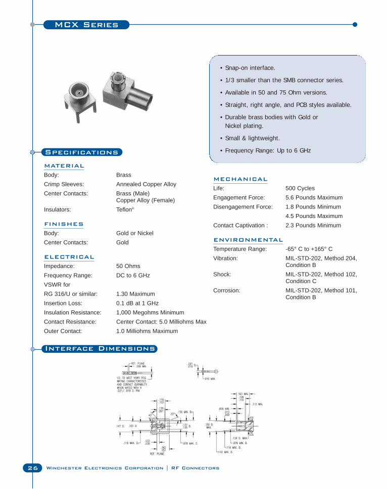
Specifications
MATERIAL
Body: BrassCrimp Sleeves: Annealed Copper AlloyCenter Contacts: Brass (Male)
Copper Alloy (Female)Insulators: Teflon®
FINISHES
Body: Gold or NickelCenter Contacts: Gold
ELECTRICAL
Impedance: 50 OhmsFrequency Range: DC to 6 GHzVSWR forRG 316/U or similar: 1.30 MaximumInsertion Loss: 0.1 dB at 1 GHzInsulation Resistance: 1,000 Megohms MinimumContact Resistance: Center Contact: 5.0 Milliohms MaxOuter Contact: 1.0 Milliohms Maximum
• Snap-on interface.
• 1/3 smaller than the SMB connector series.
• Available in 50 and 75 Ohm versions.
• Straight, right angle, and PCB styles available.
• Durable brass bodies with Gold or Nickel plating.
• Small & lightweight.
• Frequency Range: Up to 6 GHz
MECHANICAL
Life: 500 CyclesEngagement Force: 5.6 Pounds MaximumDisengagement Force: 1.8 Pounds Minimum
4.5 Pounds MaximumContact Captivation : 2.3 Pounds Minimum
ENVIRONMENTAL
Temperature Range: -65° C to +165° CVibration: MIL-STD-202, Method 204,
Condition BShock: MIL-STD-202, Method 102,
Condition CCorrosion: MIL-STD-202, Method 101,
Condition B
Interface Dimensions
Connecting Innovation to Application®MCX Series
27
MC
X S
erie
s
Figure 5
Figure 2Figure 1
Figure 6
Figure 4Figure 3
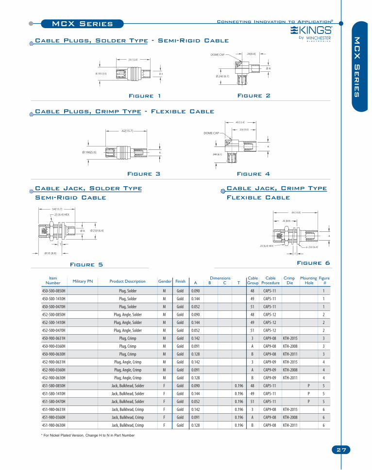
Item Dimensions Cable Cable Crimp Mounting FigureNumber Military PN Product Description Gender Finish A B C T Group Procedure Die Hole #
450-500-0850H Plug, Solder M Gold 0.090 48 CAP5-11 1
450-500-1410H Plug, Solder M Gold 0.144 49 CAP5-11 1
450-500-0470H Plug, Solder M Gold 0.052 51 CAP5-11 1
452-500-0850H Plug, Angle, Solder M Gold 0.090 48 CAP5-12 2
452-500-1410H Plug, Angle, Solder M Gold 0.144 49 CAP5-12 2
452-500-0470H Plug, Angle, Solder M Gold 0.052 51 CAP5-12 2
450-900-0631H Plug, Crimp M Gold 0.142 3 CAP9-08 KTH-2015 3
450-900-0360H Plug, Crimp M Gold 0.091 A CAP9-08 KTH-2008 3
450-900-0630H Plug, Crimp M Gold 0.128 B CAP9-08 KTH-2011 3
452-900-0631H Plug, Angle, Crimp M Gold 0.142 3 CAP9-09 KTH-2015 4
452-900-0360H Plug, Angle, Crimp M Gold 0.091 A CAP9-09 KTH-2008 4
452-900-0630H Plug, Angle, Crimp M Gold 0.128 B CAP9-09 KTH-2011 4
451-580-0850H Jack, Bulkhead, Solder F Gold 0.090 0.196 48 CAP5-11 P 5
451-580-1410H Jack, Bulkhead, Solder F Gold 0.144 0.196 49 CAP5-11 P 5
451-580-0470H Jack, Bulkhead, Solder F Gold 0.052 0.196 51 CAP5-11 P 5
451-980-0631H Jack, Bulkhead, Crimp F Gold 0.142 0.196 3 CAP9-08 KTH-2015 6
451-980-0360H Jack, Bulkhead, Crimp F Gold 0.091 0.196 A CAP9-08 KTH-2008 6
451-980-0630H Jack, Bulkhead, Crimp F Gold 0.128 0.196 B CAP9-08 KTH-2011 6
* For Nickel Plated Version, Change H to N in Part Number
Cable Plugs, Solder Type - Semi-Rigid Cable
Cable Plugs, Crimp Type - Flexible Cable
Cable Jack, Solder TypeSemi-Rigid Cable
Cable Jack, Crimp TypeFlexible Cable
MCX Series
28 Winchester Electronics Corporation | RF Connectors
Figure 7 Figure 8
Figure 9
Figure 11 Figure 12
Figure 10_1 Figure 10_2
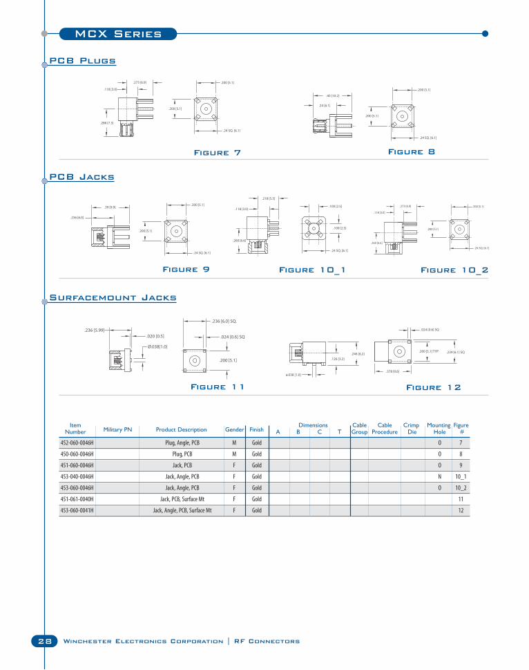
Item Dimensions Cable Cable Crimp Mounting FigureNumber Military PN Product Description Gender Finish A B C T Group Procedure Die Hole #
452-060-0046H Plug, Angle, PCB M Gold O 7
450-060-0046H Plug, PCB M Gold O 8
451-060-0046H Jack, PCB F Gold O 9
453-040-0046H Jack, Angle, PCB F Gold N 10_1
453-060-0046H Jack, Angle, PCB F Gold O 10_2
451-061-0040H Jack, PCB, Surface Mt F Gold 11
453-060-0041H Jack, Angle, PCB, Surface Mt F Gold 12
PCB Plugs
PCB Jacks
Surfacemount Jacks
Connecting Innovation to Application®MMCX Series
29
MM
CX S
erie
s
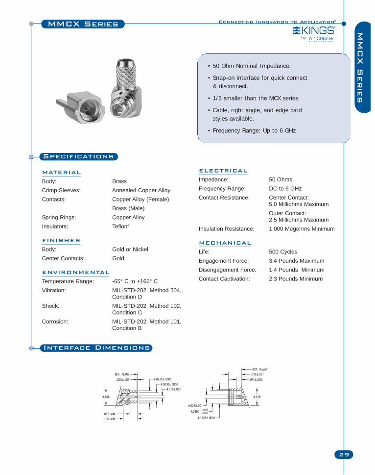
Specifications
MATERIAL
Body: BrassCrimp Sleeves: Annealed Copper AlloyContacts: Copper Alloy (Female)
Brass (Male)Spring Rings: Copper AlloyInsulators: Teflon®
FINISHES
Body: Gold or NickelCenter Contacts: Gold
ENVIRONMENTAL
Temperature Range: -65° C to +165° CVibration: MIL-STD-202, Method 204,
Condition DShock: MIL-STD-202, Method 102,
Condition CCorrosion: MIL-STD-202, Method 101,
Condition B
• 50 Ohm Nominal Impedance.
• Snap-on interface for quick connect & disconnect.
• 1/3 smaller than the MCX series.
• Cable, right angle, and edge card styles available.
• Frequency Range: Up to 6 GHz
ELECTRICAL
Impedance: 50 OhmsFrequency Range: DC to 6 GHzContact Resistance: Center Contact:
5.0 Milliohms MaximumOuter Contact: 2.5 Milliohms Maximum
Insulation Resistance: 1,000 Megohms Minimum
MECHANICAL
Life: 500 CyclesEngagement Force: 3.4 Pounds MaximumDisengagement Force: 1.4 Pounds MinimumContact Captivation: 2.3 Pounds Minimum
Interface Dimensions

MMCX Series
30 Winchester Electronics Corporation | RF Connectors
Figure 3
Figure 2Figure 1
Figure 6Figure 5
Figure 4
Item Dimensions Cable Cable Crimp Mounting FigureNumber Military PN Product Description Gender Finish A B C D Group Procedure Die Hole #
470-900-0631H Plug, Crimp M Gold 0.142 3 CAP9-17 KTH-2015 1
470-900-0361H Plug, Crimp M Gold 0.106 52 CAP9-17 KTH-2011 1
470-900-1000H Plug, Crimp M Gold 0.128 82 CAP9-17 KTH-2011 1
470-900-0360H Plug, Crimp M Gold 0.091 A CAP9-17 KTH-2008 1
470-900-0630H Plug, Crimp M Gold 0.128 B CAP9-17 KTH-2011 1
472-900-0631H Plug, Angle, Crimp M Gold 0.142 3 CAP9-18 KTH-2015 2
472-900-0361H Plug, Angle, Crimp M Gold 0.106 52 CAP9-18 KTH-2011 2
472-900-1000H Plug, Angle, Crimp M Gold 0.128 82 CAP9-18 KTH-2011 2
472-900-0360H Plug, Angle, Crimp M Gold 0.091 A CAP9-18 KTH-2008 2
472-900-0630H Plug, Angle, Crimp M Gold 0.128 B CAP9-18 2
471-900-0631H Jack, Crimp F Gold 0.142 3 CAP9-17 KTH-2015 3
471-900-0361H Jack, Crimp F Gold 0.106 52 CAP9-17 KTH-2011 3
471-900-1000H Jack, Crimp F Gold 0.128 82 CAP9-17 KTH-2011 3
471-900-0360H Jack, Crimp F Gold 0.091 A CAP9-17 KTH-2008 3
471-900-0630H Jack, Crimp F Gold 0.128 B CAP9-17 KTH-2011 3
472-900-0850H Plug, Angle, Solder M Gold 0.090 50 CAP5-18 4
472-900-0470H Plug, Angle, Solder M Gold 0.052 51 CAP5-18 4
470-500-0850H Plug, Solder M Gold 0.090 50 CAP5-17 5
470-500-0470H Plug, Solder M Gold 0.052 51 CAP5-17 5
471-500-0850H Jack, Solder F Gold 0.090 50 CAP5-17 6
471-500-0470H Jack, Solder F Gold 0.052 51 CAP5-17 6
* For Nickel Plated Version, Change H to N in Part Number
Cable Jack, Solder TypeSemi-Rigid Cable
Cable Jack, Crimp TypeFlexible Cable
Cable Plugs, Crimp Type - Flexible Cable
Cable Plugs, Solder Type - Semi-Rigid Cable
Connecting Innovation to Application®
31
MM
CX S
erie
sMMCX Series
Figure 9
Figure 8Figure 7
Figure 10
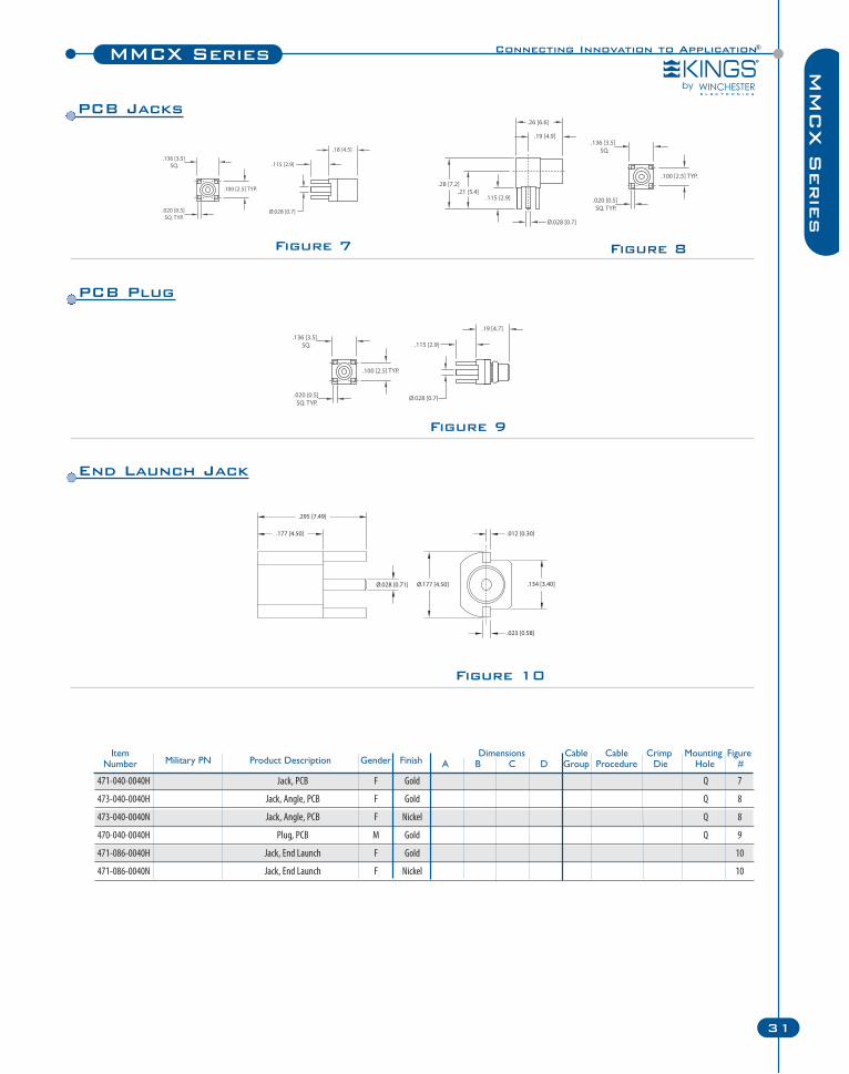
Item Dimensions Cable Cable Crimp Mounting FigureNumber Military PN Product Description Gender Finish A B C D Group Procedure Die Hole #
471-040-0040H Jack, PCB F Gold Q 7
473-040-0040H Jack, Angle, PCB F Gold Q 8
473-040-0040N Jack, Angle, PCB F Nickel Q 8
470-040-0040H Plug, PCB M Gold Q 9
471-086-0040H Jack, End Launch F Gold 10
471-086-0040N Jack, End Launch F Nickel 10
PCB Jacks
PCB Plug
End Launch Jack
N Series
32 Winchester Electronics Corporation | RF Connectors
Specifications
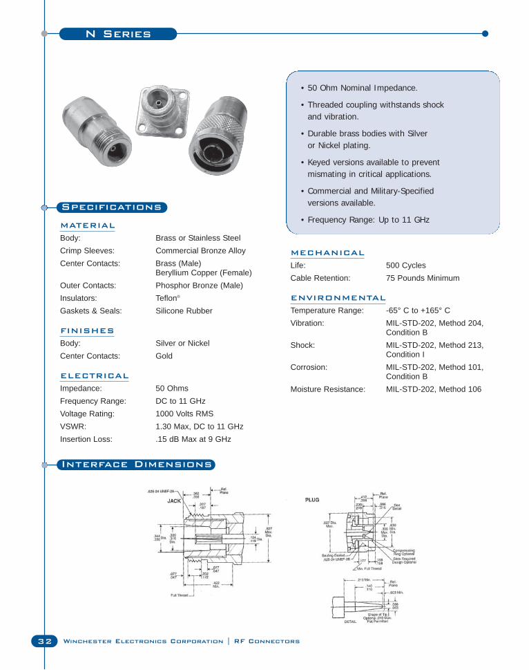
MATERIAL
Body: Brass or Stainless SteelCrimp Sleeves: Commercial Bronze AlloyCenter Contacts: Brass (Male)
Beryllium Copper (Female)Outer Contacts: Phosphor Bronze (Male)Insulators: Teflon®
Gaskets & Seals: Silicone Rubber
FINISHES
Body: Silver or NickelCenter Contacts: Gold
ELECTRICAL
Impedance: 50 OhmsFrequency Range: DC to 11 GHzVoltage Rating: 1000 Volts RMSVSWR: 1.30 Max, DC to 11 GHzInsertion Loss: .15 dB Max at 9 GHz
• 50 Ohm Nominal Impedance.
• Threaded coupling withstands shockand vibration.
• Durable brass bodies with Silver or Nickel plating.
• Keyed versions available to preventmismating in critical applications.
• Commercial and Military-Specifiedversions available.
• Frequency Range: Up to 11 GHz
MECHANICAL
Life: 500 CyclesCable Retention: 75 Pounds Minimum
ENVIRONMENTAL
Temperature Range: -65° C to +165° CVibration: MIL-STD-202, Method 204,
Condition BShock: MIL-STD-202, Method 213,
Condition ICorrosion: MIL-STD-202, Method 101,
Condition BMoisture Resistance: MIL-STD-202, Method 106
Interface Dimensions
Connecting Innovation to Application®N Series
33
N S
erie
s
Figure 1 Figure 2
Figure 3 Figure 4
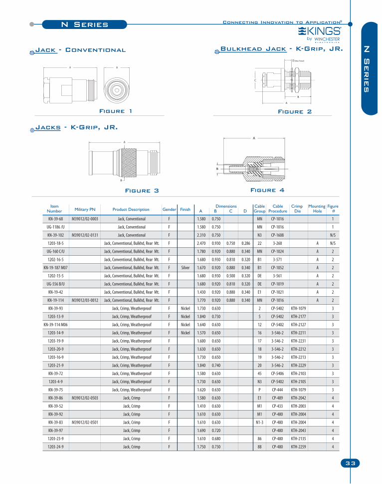
Item Dimensions Cable Cable Crimp Mounting FigureNumber Military PN Product Description Gender Finish A B C D Group Procedure Die Hole #
KN-39-68 M39012/02-0003 Jack, Conventional F 1.580 0.750 MN CP-1016 1
UG-1186 /U Jack, Conventional F 1.580 0.750 MN CP-1016 1
KN-39-102 M39012/02-0131 Jack, Conventional F 2.310 0.750 N3 CP-1608 N/S
1203-18-5 Jack, Conventional, Bulkhd, Rear Mt. F 2.470 0.930 0.750 0.286 22 3-260 A N/S
UG-160 C/U Jack, Conventional, Bulkhd, Rear Mt. F 1.780 0.920 0.880 0.340 MN CP-1024 A 2
1202-16-5 Jack, Conventional, Bulkhd, Rear Mt. F 1.680 0.930 0.810 0.320 B1 3-571 A 2
KN-19-187 M07 Jack, Conventional, Bulkhd, Rear Mt. F Silver 1.670 0.920 0.880 0.340 B1 CP-1052 A 2
1202-15-5 Jack, Conventional, Bulkhd, Rear Mt. F 1.680 0.930 0.500 0.320 DE 3-561 A 2
UG-556 B/U Jack, Conventional, Bulkhd, Rear Mt. F 1.680 0.920 0.810 0.320 DE CP-1019 A 2
KN-19-42 Jack, Conventional, Bulkhd, Rear Mt. F 1.430 0.920 0.880 0.340 E1 CP-1021 A 2
KN-19-114 M39012/03-0012 Jack, Conventional, Bulkhd, Rear Mt. F 1.770 0.920 0.880 0.340 MN CP-1016 A 2
KN-39-93 Jack, Crimp, Weatherproof F Nickel 1.730 0.630 2 CP-5402 KTH-1079 3
1203-13-9 Jack, Crimp, Weatherproof F Nickel 1.840 0.730 5 CP-5402 KTH-2177 3
KN-39-114 M06 Jack, Crimp, Weatherproof F Nickel 1.640 0.630 12 CP-5402 KTH-2127 3
1203-14-9 Jack, Crimp, Weatherproof F Nickel 1.570 0.650 16 3-546-2 KTH-2211 3
1203-19-9 Jack, Crimp, Weatherproof F 1.600 0.650 17 3-546-2 KTH-2231 3
1203-20-9 Jack, Crimp, Weatherproof F 1.630 0.650 18 3-546-2 KTH-2212 3
1203-16-9 Jack, Crimp, Weatherproof F 1.730 0.650 19 3-546-2 KTH-2213 3
1203-21-9 Jack, Crimp, Weatherproof F 1.840 0.740 20 3-546-2 KTH-2229 3
KN-39-72 Jack, Crimp, Weatherproof F 1.580 0.630 45 CP-5406 KTH-2103 3
1203-4-9 Jack, Crimp, Weatherproof F 1.730 0.630 N3 CP-5402 KTH-2105 3
KN-39-75 Jack, Crimp, Weatherproof F 1.620 0.630 P CP-444 KTH-1079 3
KN-39-86 M39012/02-0503 Jack, Crimp F 1.580 0.630 E1 CP-489 KTH-2042 4
KN-39-52 Jack, Crimp F 1.410 0.630 M1 CP-433 KTH-2003 4
KN-39-92 Jack, Crimp F 1.610 0.630 M1 CP-480 KTH-2004 4
KN-39-83 M39012/02-0501 Jack, Crimp F 1.610 0.630 N1-3 CP-480 KTH-2004 4
KN-39-97 Jack, Crimp F 1.690 0.720 CP-480 KTH-2043 4
1203-23-9 Jack, Crimp F 1.610 0.680 86 CP-480 KTH-2135 4
1203-24-9 Jack, Crimp F 1.750 0.730 88 CP-480 KTH-2259 4
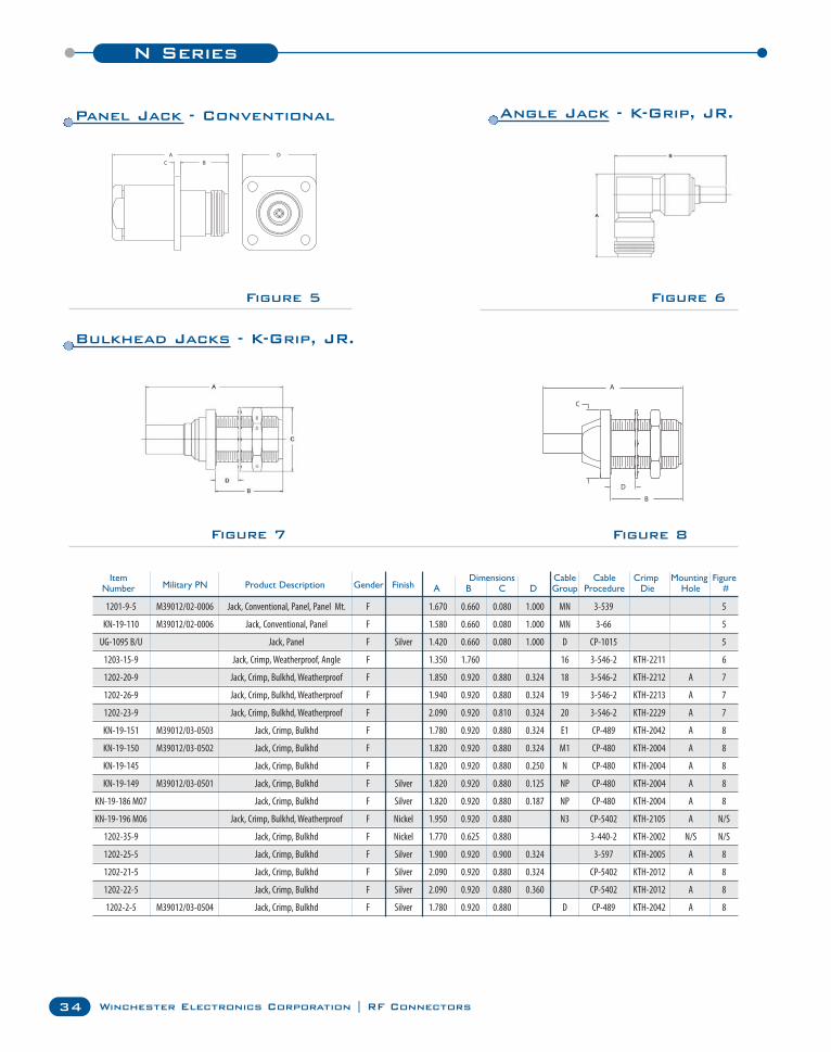
Jack - Conventional Bulkhead Jack - K-Grip, JR.
Jacks - K-Grip, JR.
N Series
34 Winchester Electronics Corporation | RF Connectors
Figure 5 Figure 6
Figure 7 Figure 8
Item Dimensions Cable Cable Crimp Mounting FigureNumber Military PN Product Description Gender Finish A B C D Group Procedure Die Hole #
1201-9-5 M39012/02-0006 Jack, Conventional, Panel, Panel Mt. F 1.670 0.660 0.080 1.000 MN 3-539 5
KN-19-110 M39012/02-0006 Jack, Conventional, Panel F 1.580 0.660 0.080 1.000 MN 3-66 5
UG-1095 B/U Jack, Panel F Silver 1.420 0.660 0.080 1.000 D CP-1015 5
1203-15-9 Jack, Crimp, Weatherproof, Angle F 1.350 1.760 16 3-546-2 KTH-2211 6
1202-20-9 Jack, Crimp, Bulkhd, Weatherproof F 1.850 0.920 0.880 0.324 18 3-546-2 KTH-2212 A 7
1202-26-9 Jack, Crimp, Bulkhd, Weatherproof F 1.940 0.920 0.880 0.324 19 3-546-2 KTH-2213 A 7
1202-23-9 Jack, Crimp, Bulkhd, Weatherproof F 2.090 0.920 0.810 0.324 20 3-546-2 KTH-2229 A 7
KN-19-151 M39012/03-0503 Jack, Crimp, Bulkhd F 1.780 0.920 0.880 0.324 E1 CP-489 KTH-2042 A 8
KN-19-150 M39012/03-0502 Jack, Crimp, Bulkhd F 1.820 0.920 0.880 0.324 M1 CP-480 KTH-2004 A 8
KN-19-145 Jack, Crimp, Bulkhd F 1.820 0.920 0.880 0.250 N CP-480 KTH-2004 A 8
KN-19-149 M39012/03-0501 Jack, Crimp, Bulkhd F Silver 1.820 0.920 0.880 0.125 NP CP-480 KTH-2004 A 8
KN-19-186 M07 Jack, Crimp, Bulkhd F Silver 1.820 0.920 0.880 0.187 NP CP-480 KTH-2004 A 8
KN-19-196 M06 Jack, Crimp, Bulkhd, Weatherproof F Nickel 1.950 0.920 0.880 N3 CP-5402 KTH-2105 A N/S
1202-35-9 Jack, Crimp, Bulkhd F Nickel 1.770 0.625 0.880 3-440-2 KTH-2002 N/S N/S
1202-25-5 Jack, Crimp, Bulkhd F Silver 1.900 0.920 0.900 0.324 3-597 KTH-2005 A 8
1202-21-5 Jack, Crimp, Bulkhd F Silver 2.090 0.920 0.880 0.324 CP-5402 KTH-2012 A 8
1202-22-5 Jack, Crimp, Bulkhd F Silver 2.090 0.920 0.880 0.360 CP-5402 KTH-2012 A 8
1202-2-5 M39012/03-0504 Jack, Crimp, Bulkhd F Silver 1.780 0.920 0.880 D CP-489 KTH-2042 A 8
Panel Jack - Conventional Angle Jack - K-Grip, JR.
Bulkhead Jacks - K-Grip, JR.
Connecting Innovation to Application®N Series
35
N S
erie
s
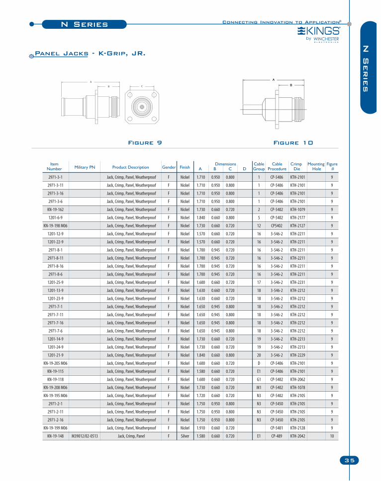
Figure 9 Figure 10
Item Dimensions Cable Cable Crimp Mounting FigureNumber Military PN Product Description Gender Finish A B C D Group Procedure Die Hole #
2971-3-1 Jack, Crimp, Panel, Weatherproof F Nickel 1.710 0.950 0.800 1 CP-5406 KTH-2101 9
2971-3-11 Jack, Crimp, Panel, Weatherproof F Nickel 1.710 0.950 0.800 1 CP-5406 KTH-2101 9
2971-3-16 Jack, Crimp, Panel, Weatherproof F Nickel 1.710 0.950 0.800 1 CP-5406 KTH-2101 9
2971-3-6 Jack, Crimp, Panel, Weatherproof F Nickel 1.710 0.950 0.800 1 CP-5406 KTH-2101 9
KN-19-162 Jack, Crimp, Panel, Weatherproof F Nickel 1.730 0.660 0.720 2 CP-5402 KTH-1079 9
1201-6-9 Jack, Crimp, Panel, Weatherproof F Nickel 1.840 0.660 0.800 5 CP-5402 KTH-2177 9
KN-19-198 M06 Jack, Crimp, Panel, Weatherproof F Nickel 1.730 0.660 0.720 12 CP5402 KTH-2127 9
1201-12-9 Jack, Crimp, Panel, Weatherproof F Nickel 1.570 0.660 0.720 16 3-546-2 KTH-2211 9
1201-22-9 Jack, Crimp, Panel, Weatherproof F Nickel 1.570 0.660 0.720 16 3-546-2 KTH-2211 9
2971-8-1 Jack, Crimp, Panel, Weatherproof F Nickel 1.700 0.945 0.720 16 3-546-2 KTH-2211 9
2971-8-11 Jack, Crimp, Panel, Weatherproof F Nickel 1.700 0.945 0.720 16 3-546-2 KTH-2211 9
2971-8-16 Jack, Crimp, Panel, Weatherproof F Nickel 1.700 0.945 0.720 16 3-546-2 KTH-2211 9
2971-8-6 Jack, Crimp, Panel, Weatherproof F Nickel 1.700 0.945 0.720 16 3-546-2 KTH-2211 9
1201-25-9 Jack, Crimp, Panel, Weatherproof F Nickel 1.600 0.660 0.720 17 3-546-2 KTH-2231 9
1201-13-9 Jack, Crimp, Panel, Weatherproof F Nickel 1.630 0.660 0.720 18 3-546-2 KTH-2212 9
1201-23-9 Jack, Crimp, Panel, Weatherproof F Nickel 1.630 0.660 0.720 18 3-546-2 KTH-2212 9
2971-7-1 Jack, Crimp, Panel, Weatherproof F Nickel 1.650 0.945 0.800 18 3-546-2 KTH-2212 9
2971-7-11 Jack, Crimp, Panel, Weatherproof F Nickel 1.650 0.945 0.800 18 3-546-2 KTH-2212 9
2971-7-16 Jack, Crimp, Panel, Weatherproof F Nickel 1.650 0.945 0.800 18 3-546-2 KTH-2212 9
2971-7-6 Jack, Crimp, Panel, Weatherproof F Nickel 1.650 0.945 0.800 18 3-546-2 KTH-2212 9
1201-14-9 Jack, Crimp, Panel, Weatherproof F Nickel 1.730 0.660 0.720 19 3-546-2 KTH-2213 9
1201-24-9 Jack, Crimp, Panel, Weatherproof F Nickel 1.730 0.660 0.720 19 3-546-2 KTH-2213 9
1201-21-9 Jack, Crimp, Panel, Weatherproof F Nickel 1.840 0.660 0.800 20 3-546-2 KTH-2229 9
KN-19-205 M06 Jack, Crimp, Panel, Weatherproof F Nickel 1.600 0.660 0.720 D CP-5406 KTH-2101 9
KN-19-115 Jack, Crimp, Panel, Weatherproof F Nickel 1.580 0.660 0.720 E1 CP-5406 KTH-2101 9
KN-19-118 Jack, Crimp, Panel, Weatherproof F Nickel 1.600 0.660 0.720 G1 CP-5402 KTH-2062 9
KN-19-208 M06 Jack, Crimp, Panel, Weatherproof F Nickel 1.730 0.660 0.720 M1 CP-5402 KTH-1078 9
KN-19-195 M06 Jack, Crimp, Panel, Weatherproof F Nickel 1.720 0.660 0.720 N3 CP-5402 KTH-2105 9
2971-2-1 Jack, Crimp, Panel, Weatherproof F Nickel 1.750 0.950 0.800 N3 CP-5450 KTH-2105 9
2971-2-11 Jack, Crimp, Panel, Weatherproof F Nickel 1.750 0.950 0.800 N3 CP-5450 KTH-2105 9
2971-2-16 Jack, Crimp, Panel, Weatherproof F Nickel 1.750 0.950 0.800 N3 CP-5450 KTH-2105 9
KN-19-199 M06 Jack, Crimp, Panel, Weatherproof F Nickel 1.910 0.660 0.720 CP-5401 KTH-2128 9
KN-19-148 M39012/02-0513 Jack, Crimp, Panel F Silver 1.580 0.660 0.720 E1 CP-489 KTH-2042 10
Panel Jacks - K-Grip, JR.
N Series
36 Winchester Electronics Corporation | RF Connectors
Figure 11
Figure 13
Figure 12
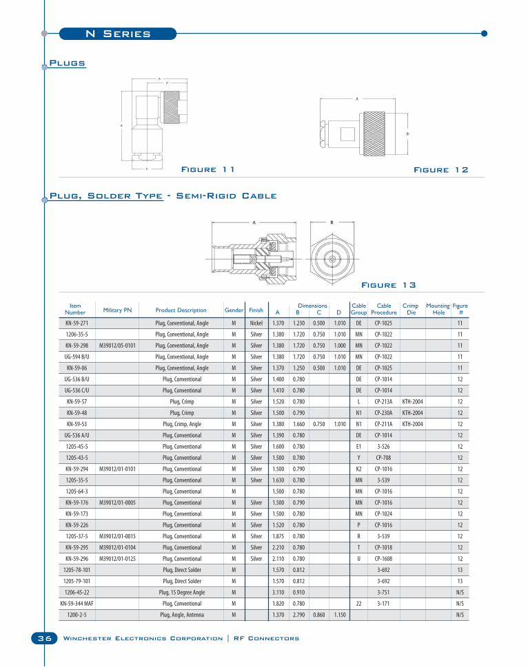
Item Dimensions Cable Cable Crimp Mounting FigureNumber Military PN Product Description Gender Finish A B C D Group Procedure Die Hole #
KN-59-271 Plug, Conventional, Angle M Nickel 1.370 1.230 0.500 1.010 DE CP-1025 11
1206-35-5 Plug, Conventional, Angle M Silver 1.380 1.720 0.750 1.010 MN CP-1022 11
KN-59-298 M39012/05-0101 Plug, Conventional, Angle M Silver 1.380 1.720 0.750 1.000 MN CP-1022 11
UG-594 B/U Plug, Conventional, Angle M Silver 1.380 1.720 0.750 1.010 MN CP-1022 11
KN-59-06 Plug, Conventional, Angle M Silver 1.370 1.250 0.500 1.010 DE CP-1025 11
UG-536 B/U Plug, Conventional M Silver 1.400 0.780 DE CP-1014 12
UG-536 C/U Plug, Conventional M Silver 1.410 0.780 DE CP-1014 12
KN-59-57 Plug, Crimp M Silver 1.520 0.780 L CP-213A KTH-2004 12
KN-59-48 Plug, Crimp M Silver 1.500 0.790 N1 CP-230A KTH-2004 12
KN-59-53 Plug, Crimp, Angle M Silver 1.380 1.660 0.750 1.010 N1 CP-211A KTH-2004 12
UG-536 A/U Plug, Conventional M Silver 1.390 0.780 DE CP-1014 12
1205-45-5 Plug, Conventional M Silver 1.600 0.780 E1 3-526 12
1205-43-5 Plug, Conventional M Silver 1.500 0.780 Y CP-708 12
KN-59-294 M39012/01-0101 Plug, Conventional M Silver 1.500 0.790 K2 CP-1016 12
1205-35-5 Plug, Conventional M Silver 1.630 0.780 MN 3-539 12
1205-64-3 Plug, Conventional M 1.500 0.780 MN CP-1016 12
KN-59-176 M39012/01-0005 Plug, Conventional M Silver 1.500 0.790 MN CP-1016 12
KN-59-173 Plug, Conventional M Silver 1.500 0.780 MN CP-1024 12
KN-59-226 Plug, Conventional M Silver 1.520 0.780 P CP-1016 12
1205-37-5 M39012/01-0015 Plug, Conventional M Silver 1.875 0.780 R 3-539 12
KN-59-295 M39012/01-0104 Plug, Conventional M Silver 2.210 0.780 T CP-1018 12
KN-59-296 M39012/01-0125 Plug, Conventional M Silver 2.110 0.780 U CP-1608 12
1205-78-101 Plug, Direct Solder M 1.570 0.812 3-692 13
1205-79-101 Plug, Direct Solder M 1.570 0.812 3-692 13
1206-45-22 Plug, 15 Degree Angle M 3.110 0.910 3-751 N/S
KN-59-344 MAF Plug, Conventional M 1.820 0.780 22 3-171 N/S
1200-2-5 Plug, Angle, Antenna M 1.370 2.790 0.860 1.150 N/S
Plugs
Plug, Solder Type - Semi-Rigid Cable
Connecting Innovation to Application®N Series
37
N S
erie
s
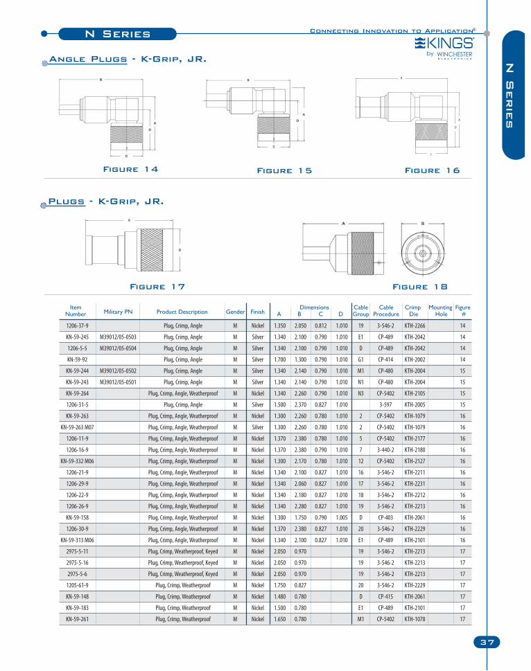
Figure 17 Figure 18
Figure 14 Figure 15 Figure 16
Item Dimensions Cable Cable Crimp Mounting FigureNumber Military PN Product Description Gender Finish A B C D Group Procedure Die Hole #
1206-37-9 Plug, Crimp, Angle M Nickel 1.350 2.050 0.812 1.010 19 3-546-2 KTH-2266 14
KN-59-245 M39012/05-0503 Plug, Crimp, Angle M Silver 1.340 2.100 0.790 1.010 E1 CP-489 KTH-2042 14
1206-5-5 M39012/05-0504 Plug, Crimp, Angle M Silver 1.340 2.100 0.790 1.010 D CP-489 KTH-2042 14
KN-59-92 Plug, Crimp, Angle M Silver 1.700 1.300 0.790 1.010 G1 CP-414 KTH-2002 14
KN-59-244 M39012/05-0502 Plug, Crimp, Angle M Silver 1.340 2.140 0.790 1.010 M1 CP-480 KTH-2004 15
KN-59-243 M39012/05-0501 Plug, Crimp, Angle M Silver 1.340 2.140 0.790 1.010 N1 CP-480 KTH-2004 15
KN-59-264 Plug, Crimp, Angle, Weatherproof M Nickel 1.340 2.260 0.790 1.010 N3 CP-5402 KTH-2105 15
1206-31-5 Plug, Crimp, Angle M Silver 1.500 2.370 0.827 1.010 3-597 KTH-2005 15
KN-59-263 Plug, Crimp, Angle, Weatherproof M Nickel 1.300 2.260 0.780 1.010 2 CP-5402 KTH-1079 16
KN-59-263 M07 Plug, Crimp, Angle, Weatherproof M Silver 1.300 2.260 0.780 1.010 2 CP-5402 KTH-1079 16
1206-11-9 Plug, Crimp, Angle, Weatherproof M Nickel 1.370 2.380 0.780 1.010 5 CP-5402 KTH-2177 16
1206-16-9 Plug, Crimp, Angle, Weatherproof M Nickel 1.370 2.380 0.790 1.010 7 3-440-2 KTH-2180 16
KN-59-332 M06 Plug, Crimp, Angle, Weatherproof M Nickel 1.300 2.170 0.780 1.010 12 CP-5402 KTH-2127 16
1206-21-9 Plug, Crimp, Angle, Weatherproof M Nickel 1.340 2.100 0.827 1.010 16 3-546-2 KTH-2211 16
1206-29-9 Plug, Crimp, Angle, Weatherproof M Nickel 1.340 2.060 0.827 1.010 17 3-546-2 KTH-2231 16
1206-22-9 Plug, Crimp, Angle, Weatherproof M Nickel 1.340 2.180 0.827 1.010 18 3-546-2 KTH-2212 16
1206-26-9 Plug, Crimp, Angle, Weatherproof M Nickel 1.340 2.280 0.827 1.010 19 3-546-2 KTH-2213 16
KN-59-158 Plug, Crimp, Angle, Weatherproof M Nickel 1.300 1.750 0.790 1.005 D CP-403 KTH-2061 16
1206-30-9 Plug, Crimp, Angle, Weatherproof M Nickel 1.370 2.380 0.827 1.010 20 3-546-2 KTH-2229 16
KN-59-313 M06 Plug, Crimp, Angle, Weatherproof M Nickel 1.340 2.100 0.827 1.010 E1 CP-489 KTH-2101 16
2975-5-11 Plug, Crimp, Weatherproof, Keyed M Nickel 2.050 0.970 19 3-546-2 KTH-2213 17
2975-5-16 Plug, Crimp, Weatherproof, Keyed M Nickel 2.050 0.970 19 3-546-2 KTH-2213 17
2975-5-6 Plug, Crimp, Weatherproof, Keyed M Nickel 2.050 0.970 19 3-546-2 KTH-2213 17
1205-61-9 Plug, Crimp, Weatherproof M Nickel 1.750 0.827 20 3-546-2 KTH-2229 17
KN-59-148 Plug, Crimp, Weatherproof M Nickel 1.480 0.780 D CP-415 KTH-2061 17
KN-59-183 Plug, Crimp, Weatherproof M Nickel 1.500 0.780 E1 CP-489 KTH-2101 17
KN-59-261 Plug, Crimp, Weatherproof M Nickel 1.650 0.780 M1 CP-5402 KTH-1078 17
Plugs - K-Grip, JR.
Angle Plugs - K-Grip, JR.
N Series
38 Winchester Electronics Corporation | RF Connectors
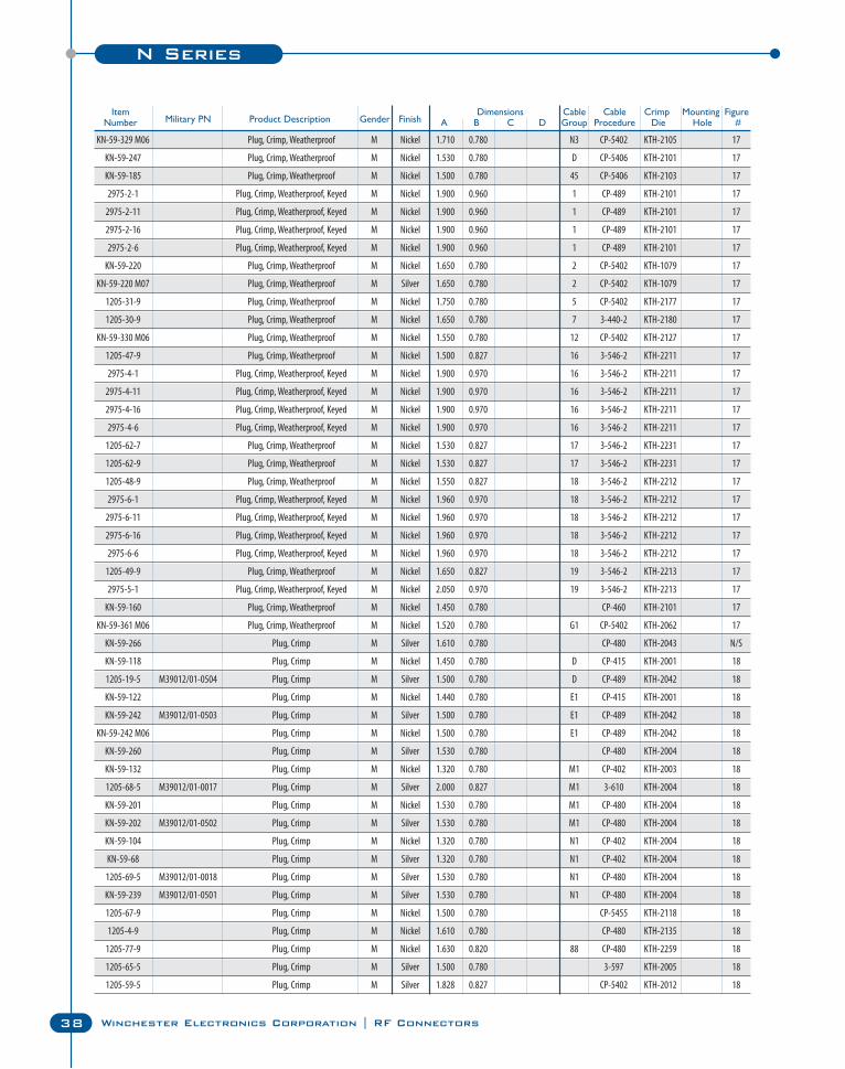
KN-59-329 M06 Plug, Crimp, Weatherproof M Nickel 1.710 0.780 N3 CP-5402 KTH-2105 17
KN-59-247 Plug, Crimp, Weatherproof M Nickel 1.530 0.780 D CP-5406 KTH-2101 17
KN-59-185 Plug, Crimp, Weatherproof M Nickel 1.500 0.780 45 CP-5406 KTH-2103 17
2975-2-1 Plug, Crimp, Weatherproof, Keyed M Nickel 1.900 0.960 1 CP-489 KTH-2101 17
2975-2-11 Plug, Crimp, Weatherproof, Keyed M Nickel 1.900 0.960 1 CP-489 KTH-2101 17
2975-2-16 Plug, Crimp, Weatherproof, Keyed M Nickel 1.900 0.960 1 CP-489 KTH-2101 17
2975-2-6 Plug, Crimp, Weatherproof, Keyed M Nickel 1.900 0.960 1 CP-489 KTH-2101 17
KN-59-220 Plug, Crimp, Weatherproof M Nickel 1.650 0.780 2 CP-5402 KTH-1079 17
KN-59-220 M07 Plug, Crimp, Weatherproof M Silver 1.650 0.780 2 CP-5402 KTH-1079 17
1205-31-9 Plug, Crimp, Weatherproof M Nickel 1.750 0.780 5 CP-5402 KTH-2177 17
1205-30-9 Plug, Crimp, Weatherproof M Nickel 1.650 0.780 7 3-440-2 KTH-2180 17
KN-59-330 M06 Plug, Crimp, Weatherproof M Nickel 1.550 0.780 12 CP-5402 KTH-2127 17
1205-47-9 Plug, Crimp, Weatherproof M Nickel 1.500 0.827 16 3-546-2 KTH-2211 17
2975-4-1 Plug, Crimp, Weatherproof, Keyed M Nickel 1.900 0.970 16 3-546-2 KTH-2211 17
2975-4-11 Plug, Crimp, Weatherproof, Keyed M Nickel 1.900 0.970 16 3-546-2 KTH-2211 17
2975-4-16 Plug, Crimp, Weatherproof, Keyed M Nickel 1.900 0.970 16 3-546-2 KTH-2211 17
2975-4-6 Plug, Crimp, Weatherproof, Keyed M Nickel 1.900 0.970 16 3-546-2 KTH-2211 17
1205-62-7 Plug, Crimp, Weatherproof M Nickel 1.530 0.827 17 3-546-2 KTH-2231 17
1205-62-9 Plug, Crimp, Weatherproof M Nickel 1.530 0.827 17 3-546-2 KTH-2231 17
1205-48-9 Plug, Crimp, Weatherproof M Nickel 1.550 0.827 18 3-546-2 KTH-2212 17
2975-6-1 Plug, Crimp, Weatherproof, Keyed M Nickel 1.960 0.970 18 3-546-2 KTH-2212 17
2975-6-11 Plug, Crimp, Weatherproof, Keyed M Nickel 1.960 0.970 18 3-546-2 KTH-2212 17
2975-6-16 Plug, Crimp, Weatherproof, Keyed M Nickel 1.960 0.970 18 3-546-2 KTH-2212 17
2975-6-6 Plug, Crimp, Weatherproof, Keyed M Nickel 1.960 0.970 18 3-546-2 KTH-2212 17
1205-49-9 Plug, Crimp, Weatherproof M Nickel 1.650 0.827 19 3-546-2 KTH-2213 17
2975-5-1 Plug, Crimp, Weatherproof, Keyed M Nickel 2.050 0.970 19 3-546-2 KTH-2213 17
KN-59-160 Plug, Crimp, Weatherproof M Nickel 1.450 0.780 CP-460 KTH-2101 17
KN-59-361 M06 Plug, Crimp, Weatherproof M Nickel 1.520 0.780 G1 CP-5402 KTH-2062 17
KN-59-266 Plug, Crimp M Silver 1.610 0.780 CP-480 KTH-2043 N/S
KN-59-118 Plug, Crimp M Nickel 1.450 0.780 D CP-415 KTH-2001 18
1205-19-5 M39012/01-0504 Plug, Crimp M Silver 1.500 0.780 D CP-489 KTH-2042 18
KN-59-122 Plug, Crimp M Nickel 1.440 0.780 E1 CP-415 KTH-2001 18
KN-59-242 M39012/01-0503 Plug, Crimp M Silver 1.500 0.780 E1 CP-489 KTH-2042 18
KN-59-242 M06 Plug, Crimp M Nickel 1.500 0.780 E1 CP-489 KTH-2042 18
KN-59-260 Plug, Crimp M Silver 1.530 0.780 CP-480 KTH-2004 18
KN-59-132 Plug, Crimp M Nickel 1.320 0.780 M1 CP-402 KTH-2003 18
1205-68-5 M39012/01-0017 Plug, Crimp M Silver 2.000 0.827 M1 3-610 KTH-2004 18
KN-59-201 Plug, Crimp M Nickel 1.530 0.780 M1 CP-480 KTH-2004 18
KN-59-202 M39012/01-0502 Plug, Crimp M Silver 1.530 0.780 M1 CP-480 KTH-2004 18
KN-59-104 Plug, Crimp M Nickel 1.320 0.780 N1 CP-402 KTH-2004 18
KN-59-68 Plug, Crimp M Silver 1.320 0.780 N1 CP-402 KTH-2004 18
1205-69-5 M39012/01-0018 Plug, Crimp M Silver 1.530 0.780 N1 CP-480 KTH-2004 18
KN-59-239 M39012/01-0501 Plug, Crimp M Silver 1.530 0.780 N1 CP-480 KTH-2004 18
1205-67-9 Plug, Crimp M Nickel 1.500 0.780 CP-5455 KTH-2118 18
1205-4-9 Plug, Crimp M Nickel 1.610 0.780 CP-480 KTH-2135 18
1205-77-9 Plug, Crimp M Nickel 1.630 0.820 88 CP-480 KTH-2259 18
1205-65-5 Plug, Crimp M Silver 1.500 0.780 3-597 KTH-2005 18
1205-59-5 Plug, Crimp M Silver 1.828 0.827 CP-5402 KTH-2012 18
Item Dimensions Cable Cable Crimp Mounting FigureNumber Military PN Product Description Gender Finish A B C D Group Procedure Die Hole #
Connecting Innovation to Application®N Series
39
N S
erie
s
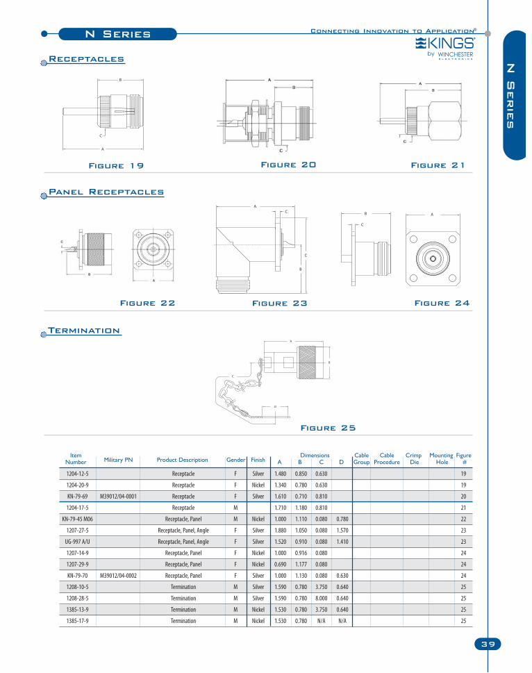
1204-12-5 Receptacle F Silver 1.480 0.850 0.630 19
1204-20-9 Receptacle F Nickel 1.340 0.780 0.630 19
KN-79-69 M39012/04-0001 Receptacle F Silver 1.610 0.710 0.810 20
1204-17-5 Receptacle M 1.710 1.180 0.810 21
KN-79-45 M06 Receptacle, Panel M Nickel 1.000 1.110 0.080 0.780 22
1207-27-5 Receptacle, Panel, Angle F Silver 1.880 1.050 0.080 1.570 23
UG-997 A/U Receptacle, Panel, Angle F Silver 1.520 0.910 0.080 1.410 23
1207-14-9 Receptacle, Panel F Nickel 1.000 0.916 0.080 24
1207-29-9 Receptacle, Panel F Nickel 0.690 1.177 0.080 24
KN-79-70 M39012/04-0002 Receptacle, Panel F Silver 1.000 1.130 0.080 0.630 24
1208-10-5 Termination M Silver 1.590 0.780 3.750 0.640 25
1208-28-5 Termination M Silver 1.590 0.780 8.000 0.640 25
1385-13-9 Termination M Nickel 1.530 0.780 3.750 0.640 25
1385-17-9 Termination M Nickel 1.530 0.780 N/A N/A 25
Item Dimensions Cable Cable Crimp Mounting FigureNumber Military PN Product Description Gender Finish A B C D Group Procedure Die Hole #
Figure 19 Figure 21Figure 20
Figure 22 Figure 23 Figure 24
Figure 25
Receptacles
Panel Receptacles
Termination
N Series
40 Winchester Electronics Corporation | RF Connectors
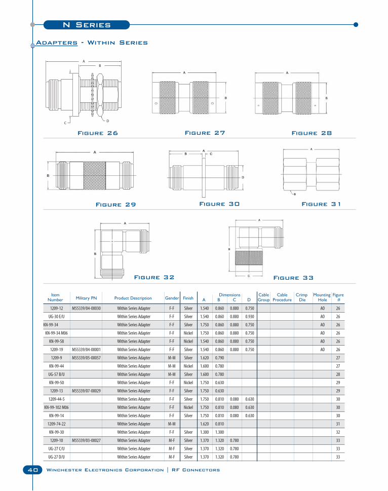
Figure 26
Figure 29 Figure 30
Figure 32
Figure 28
Figure 33
Figure 31
Figure 27
Item Dimensions Cable Cable Crimp Mounting FigureNumber Military PN Product Description Gender Finish A B C D Group Procedure Die Hole #
1209-12 M55339/04-00030 Within Series Adapter F-F Silver 1.540 0.860 0.880 0.750 AO 26
UG-30 E/U Within Series Adapter F-F Silver 1.540 0.860 0.880 0.930 AO 26
KN-99-34 Within Series Adapter F-F Silver 1.750 0.860 0.880 0.750 AO 26
KN-99-34 M06 Within Series Adapter F-F Nickel 1.750 0.860 0.880 0.750 AO 26
KN-99-58 Within Series Adapter F-F Nickel 1.540 0.860 0.880 0.750 AO 26
1209-19 M55339/04-00001 Within Series Adapter F-F Silver 1.540 0.860 0.880 0.750 AO 26
1209-9 M55339/05-00057 Within Series Adapter M-M Silver 1.620 0.790 27
KN-99-44 Within Series Adapter M-M Nickel 1.600 0.780 27
UG-57 B/U Within Series Adapter M-M Silver 1.600 0.780 28
KN-99-50 Within Series Adapter F-F Nickel 1.750 0.630 29
1209-13 M55339/07-00029 Within Series Adapter F-F Silver 1.750 0.630 29
1209-44-5 Within Series Adapter F-F Silver 1.750 0.810 0.080 0.630 30
KN-99-102 M06 Within Series Adapter F-F Nickel 1.750 0.810 0.080 0.630 30
KN-99-14 Within Series Adapter F-F Silver 1.750 0.810 0.080 0.630 30
1209-74-22 Within Series Adapter M-M 1.620 0.810 31
KN-99-30 Within Series Adapter F-F Silver 1.300 1.300 32
1209-10 M55339/03-00027 Within Series Adapter M-F Silver 1.370 1.320 0.780 33
UG-27 C/U Within Series Adapter M-F Silver 1.370 1.320 0.780 33
UG-27 D/U Within Series Adapter M-F Silver 1.370 1.320 0.780 33
Adapters - Within Series
Connecting Innovation to Application®N Series
41
N S
erie
s
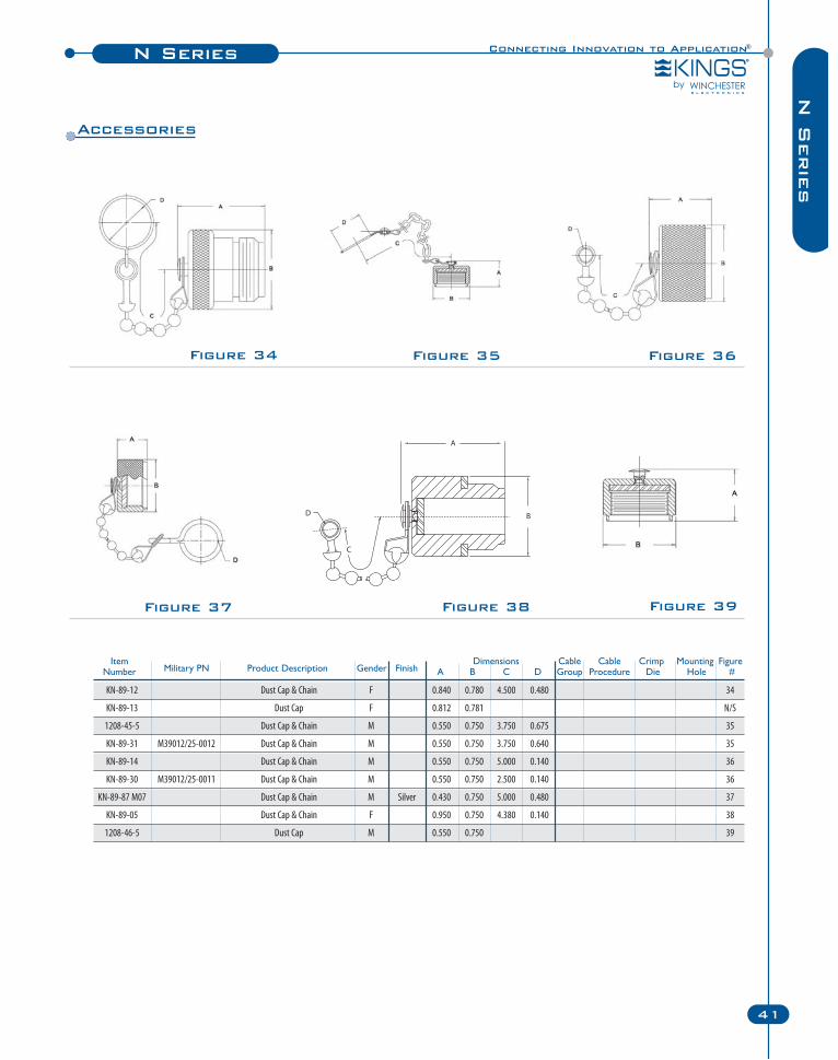
KN-89-12 Dust Cap & Chain F 0.840 0.780 4.500 0.480 34
KN-89-13 Dust Cap F 0.812 0.781 N/S
1208-45-5 Dust Cap & Chain M 0.550 0.750 3.750 0.675 35
KN-89-31 M39012/25-0012 Dust Cap & Chain M 0.550 0.750 3.750 0.640 35
KN-89-14 Dust Cap & Chain M 0.550 0.750 5.000 0.140 36
KN-89-30 M39012/25-0011 Dust Cap & Chain M 0.550 0.750 2.500 0.140 36
KN-89-87 M07 Dust Cap & Chain M Silver 0.430 0.750 5.000 0.480 37
KN-89-05 Dust Cap & Chain F 0.950 0.750 4.380 0.140 38
1208-46-5 Dust Cap M 0.550 0.750 39
Figure 38
Figure 34 Figure 35
Figure 39
Figure 36
Figure 37
Item Dimensions Cable Cable Crimp Mounting FigureNumber Military PN Product Description Gender Finish A B C D Group Procedure Die Hole #
Accessories
QC-N Series
42 Winchester Electronics Corporation | RF Connectors
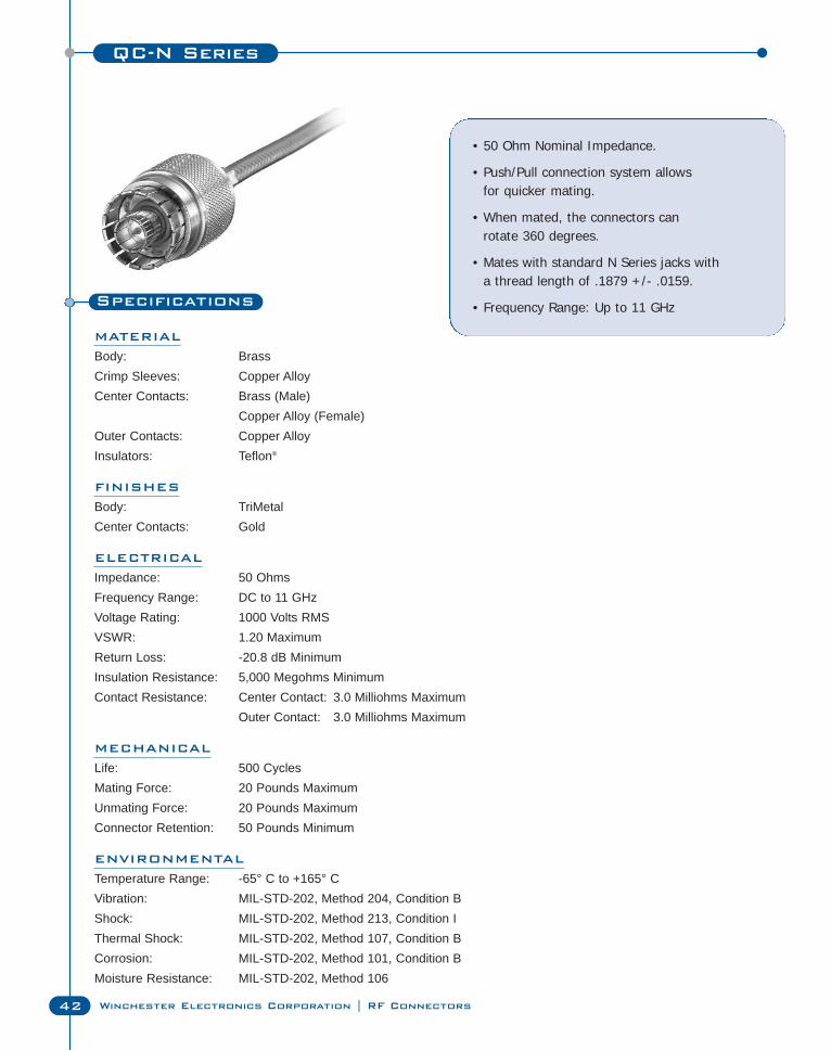
Specifications
MATERIAL
Body: BrassCrimp Sleeves: Copper AlloyCenter Contacts: Brass (Male)
Copper Alloy (Female)Outer Contacts: Copper AlloyInsulators: Teflon®
FINISHES
Body: TriMetalCenter Contacts: Gold
ELECTRICAL
Impedance: 50 OhmsFrequency Range: DC to 11 GHzVoltage Rating: 1000 Volts RMSVSWR: 1.20 MaximumReturn Loss: -20.8 dB MinimumInsulation Resistance: 5,000 Megohms MinimumContact Resistance: Center Contact: 3.0 Milliohms Maximum
Outer Contact: 3.0 Milliohms Maximum
MECHANICAL
Life: 500 CyclesMating Force: 20 Pounds MaximumUnmating Force: 20 Pounds MaximumConnector Retention: 50 Pounds Minimum
ENVIRONMENTAL
Temperature Range: -65° C to +165° CVibration: MIL-STD-202, Method 204, Condition BShock: MIL-STD-202, Method 213, Condition IThermal Shock: MIL-STD-202, Method 107, Condition BCorrosion: MIL-STD-202, Method 101, Condition BMoisture Resistance: MIL-STD-202, Method 106
• 50 Ohm Nominal Impedance.
• Push/Pull connection system allows for quicker mating.
• When mated, the connectors can rotate 360 degrees.
• Mates with standard N Series jacks with a thread length of .1879 +/- .0159.
• Frequency Range: Up to 11 GHz
Connecting Innovation to Application®QC-N Series
43
QC
-N S
erie
s
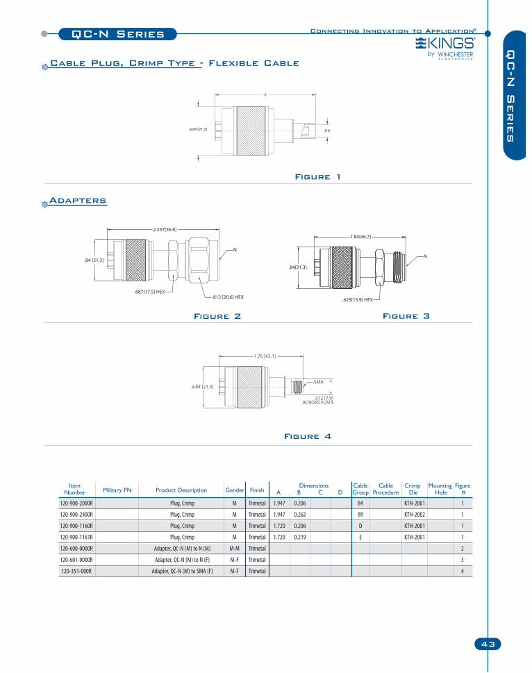
Figure 4
Figure 2 Figure 3
Figure 1
Item Dimensions Cable Cable Crimp Mounting FigureNumber Military PN Product Description Gender Finish A B C D Group Procedure Die Hole #
120-900-2000R Plug, Crimp M Trimetal 1.947 0.206 84 KTH-2001 1
120-900-2400R Plug, Crimp M Trimetal 1.947 0.262 89 KTH-2002 1
120-900-1160R Plug, Crimp M Trimetal 1.720 0.206 D KTH-2001 1
120-900-1161R Plug, Crimp M Trimetal 1.720 0.219 E KTH-2001 1
120-600-0000R Adapter, QC-N (M) to N (M) M-M Trimetal 2
120-601-0000R Adapter, QC-N (M) to N (F) M-F Trimetal 3
120-351-000R Adapter, QC-N (M) to SMA (F) M-F Trimetal 4
Cable Plug, Crimp Type - Flexible Cable
Adapters
SC Series
44 Winchester Electronics Corporation | RF Connectors
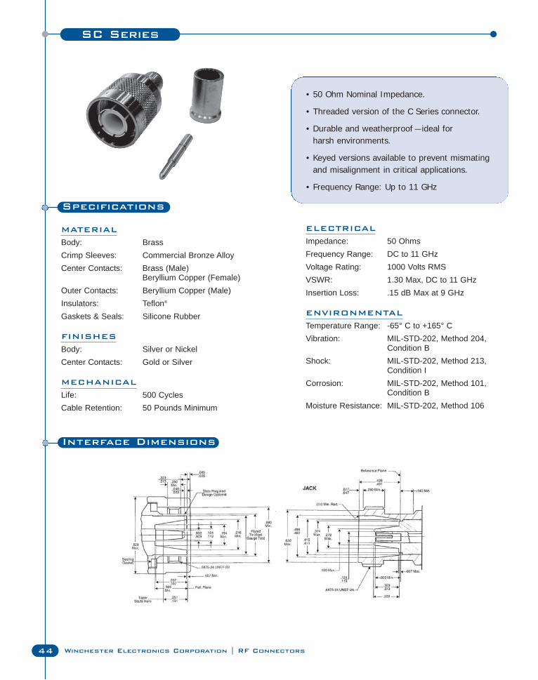
Specifications
MATERIAL
Body: BrassCrimp Sleeves: Commercial Bronze AlloyCenter Contacts: Brass (Male)
Beryllium Copper (Female)Outer Contacts: Beryllium Copper (Male)Insulators: Teflon®
Gaskets & Seals: Silicone Rubber
FINISHES
Body: Silver or NickelCenter Contacts: Gold or Silver
MECHANICAL
Life: 500 CyclesCable Retention: 50 Pounds Minimum
• 50 Ohm Nominal Impedance.
• Threaded version of the C Series connector.
• Durable and weatherproof — ideal for harsh environments.
• Keyed versions available to prevent mismatingand misalignment in critical applications.
• Frequency Range: Up to 11 GHz
ELECTRICAL
Impedance: 50 OhmsFrequency Range: DC to 11 GHzVoltage Rating: 1000 Volts RMSVSWR: 1.30 Max, DC to 11 GHzInsertion Loss: .15 dB Max at 9 GHz
ENVIRONMENTAL
Temperature Range: -65° C to +165° CVibration: MIL-STD-202, Method 204,
Condition BShock: MIL-STD-202, Method 213,
Condition ICorrosion: MIL-STD-202, Method 101,
Condition BMoisture Resistance: MIL-STD-202, Method 106
Interface Dimensions
Connecting Innovation to Application®SC Series
45
SC
Serie
s
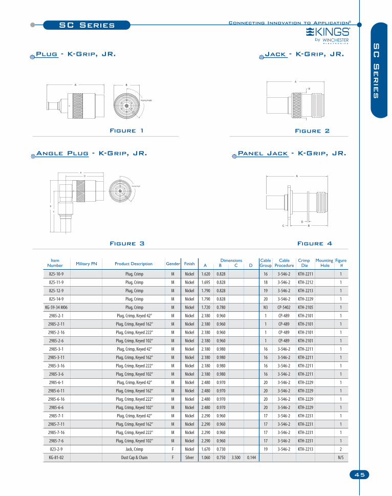
Figure 2Figure 1
825-10-9 Plug, Crimp M Nickel 1.620 0.828 16 3-546-2 KTH-2211 1
825-11-9 Plug, Crimp M Nickel 1.695 0.828 18 3-546-2 KTH-2212 1
825-12-9 Plug, Crimp M Nickel 1.790 0.828 19 3-546-2 KTH-2213 1
825-14-9 Plug, Crimp M Nickel 1.790 0.828 20 3-546-2 KTH-2229 1
KG-59-34 M06 Plug, Crimp M Nickel 1.720 0.780 N3 CP-5402 KTH-2105 1
2985-2-1 Plug, Crimp, Keyed 42° M Nickel 2.180 0.960 1 CP-489 KTH-2101 1
2985-2-11 Plug, Crimp, Keyed 162° M Nickel 2.180 0.960 1 CP-489 KTH-2101 1
2985-2-16 Plug, Crimp, Keyed 222° M Nickel 2.180 0.960 1 CP-489 KTH-2101 1
2985-2-6 Plug, Crimp, Keyed 102° M Nickel 2.180 0.960 1 CP-489 KTH-2101 1
2985-3-1 Plug, Crimp, Keyed 42° M Nickel 2.180 0.980 16 3-546-2 KTH-2211 1
2985-3-11 Plug, Crimp, Keyed 162° M Nickel 2.180 0.980 16 3-546-2 KTH-2211 1
2985-3-16 Plug, Crimp, Keyed 222° M Nickel 2.180 0.980 16 3-546-2 KTH-2211 1
2985-3-6 Plug, Crimp, Keyed 102° M Nickel 2.180 0.980 16 3-546-2 KTH-2211 1
2985-6-1 Plug, Crimp, Keyed 42° M Nickel 2.480 0.970 20 3-546-2 KTH-2229 1
2985-6-11 Plug, Crimp, Keyed 162° M Nickel 2.480 0.970 20 3-546-2 KTH-2229 1
2985-6-16 Plug, Crimp, Keyed 222° M Nickel 2.480 0.970 20 3-546-2 KTH-2229 1
2985-6-6 Plug, Crimp, Keyed 102° M Nickel 2.480 0.970 20 3-546-2 KTH-2229 1
2985-7-1 Plug, Crimp, Keyed 42° M Nickel 2.290 0.960 17 3-546-2 KTH-2231 1
2985-7-11 Plug, Crimp, Keyed 162° M Nickel 2.290 0.960 17 3-546-2 KTH-2231 1
2985-7-16 Plug, Crimp, Keyed 222° M Nickel 2.290 0.960 17 3-546-2 KTH-2231 1
2985-7-6 Plug, Crimp, Keyed 102° M Nickel 2.290 0.960 17 3-546-2 KTH-2231 1
823-2-9 Jack, Crimp F Nickel 1.670 0.730 19 3-546-2 KTH-2213 2
KG-81-02 Dust Cap & Chain F Silver 1.060 0.750 3.500 0.144 N/S
Item Dimensions Cable Cable Crimp Mounting FigureNumber Military PN Product Description Gender Finish A B C D Group Procedure Die Hole #
Figure 3 Figure 4
Plug - K-Grip, JR. Jack - K-Grip, JR.
Angle Plug - K-Grip, JR. Panel Jack - K-Grip, JR.
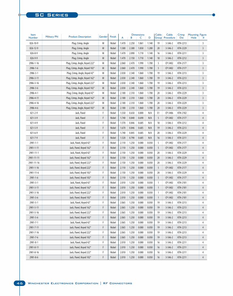
46 Winchester Electronics Corporation | RF Connectors
SC Series
826-10-9 Plug, Crimp, Angle M Nickel 1.470 2.250 1.861 1.140 19 3-546-2 KTH-2213 3
826-12-9 Plug, Crimp, Angle M Nickel 1.500 2.300 1.850 1.200 20 3-546-2 KTH-2229 3
826-8-9 Plug, Crimp, Angle M Nickel 1.470 2.090 1.710 1.140 16 3-546-2 KTH-2211 3
826-9-9 Plug, Crimp, Angle M Nickel 1.470 2.150 1.710 1.140 18 3-546-2 KTH-2212 3
2986-1-16 Plug, Crimp, Angle, Keyed 222° M Nickel 2.060 2.470 1.990 1.700 5 CP-5402 KTH-2177 3
2986-1-6 Plug, Crimp, Angle, Keyed 102° M Nickel 2.060 2.470 1.990 1.700 5 CP-5402 KTH-2177 3
2986-3-1 Plug, Crimp, Angle, Keyed 42° M Nickel 2.030 2.340 1.860 1.700 19 3-546-2 KTH-2213 3
2986-3-11 Plug, Crimp, Angle, Keyed 162° M Nickel 2.030 2.340 1.860 1.700 19 3-546-2 KTH-2213 3
2986-3-16 Plug, Crimp, Angle, Keyed 222° M Nickel 2.030 2.340 1.860 1.700 19 3-546-2 KTH-2213 3
2986-3-6 Plug, Crimp, Angle, Keyed 102° M Nickel 2.030 2.340 1.860 1.700 19 3-546-2 KTH-2213 3
2986-4-1 Plug, Crimp, Angle, Keyed 42° M Nickel 2.100 2.310 1.860 1.700 20 3-546-2 KTH-2229 3
2986-4-11 Plug, Crimp, Angle, Keyed 162° M Nickel 2.100 2.310 1.860 1.700 20 3-546-2 KTH-2229 3
2986-4-16 Plug, Crimp, Angle, Keyed 222° M Nickel 2.100 2.310 1.860 1.700 20 3-546-2 KTH-2229 3
2986-4-6 Plug, Crimp, Angle, Keyed 102° M Nickel 2.100 2.310 1.860 1.700 20 3-546-2 KTH-2229 3
821-2-9 Jack, Panel F Nickel 1.550 0.650 0.800 N/A E1 CP-5406 KTH-2102 4
821-3-9 Jack, Panel F Nickel 1.740 0.840 0.690 N/A 5 CP-5402 KTH-2177 4
821-4-9 Jack, Panel F Nickel 1.570 0.846 0.685 N/A 18 3-546-2 KTH-2212 4
821-5-9 Jack, Panel F Nickel 1.670 0.846 0.685 N/A 19 3-546-2 KTH-2213 4
821-6-9 Jack, Panel F Nickel 1.740 0.845 0.685 N/A 20 3-546-2 KTH-2229 4
821-7-9 Jack, Panel F Nickel 1.520 0.790 0.685 N/A 16 3-546-2 KTH-2211 4
2981-1-1 Jack, Panel, Keyed 42° F Nickel 2.110 1.250 0.080 0.050 5 CP-5402 KTH-2177 4
2981-1-11 Jack, Panel, Keyed 162° F Nickel 2.110 1.250 0.080 0.050 5 CP-5402 KTH-2177 4
2981-11-1 Jack, Panel, Keyed 42° F Nickel 2.150 1.250 0.080 0.050 20 3-546-2 KTH-2229 4
2981-11-11 Jack, Panel, Keyed 162° F Nickel 2.150 1.250 0.080 0.050 20 3-546-2 KTH-2229 4
2981-11-16 Jack, Panel, Keyed 222° F Nickel 2.150 1.250 0.080 0.050 20 3-546-2 KTH-2229 4
2981-1-16 Jack, Panel, Keyed 222° F Nickel 2.110 1.250 0.080 0.050 5 CP-5402 KTH-2177 4
2981-11-6 Jack, Panel, Keyed 102° F Nickel 2.150 1.250 0.080 0.050 20 3-546-2 KTH-2229 4
2981-1-6 Jack, Panel, Keyed 102° F Nickel 2.110 1.250 0.080 0.050 5 CP-5402 KTH-2177 4
2981-3-1 Jack, Panel, Keyed 42° F Nickel 2.010 1.250 0.080 0.050 1 CP-5402 KTH-2101 4
2981-3-11 Jack, Panel, Keyed 162° F Nickel 2.010 1.250 0.080 0.050 1 CP-5402 KTH-2101 4
2981-3-16 Jack, Panel, Keyed 222° F Nickel 2.010 1.250 0.080 0.050 1 CP-5402 KTH-2101 4
2981-3-6 Jack, Panel, Keyed 102° F Nickel 2.010 1.250 0.080 0.050 1 CP-5402 KTH-2101 4
2981-5-1 Jack, Panel, Keyed 42° F Nickel 2.065 1.250 0.080 0.050 19 3-546-2 KTH-2213 4
2981-5-11 Jack, Panel, Keyed 162° F Nickel 2.065 1.250 0.080 0.050 19 3-546-2 KTH-2213 4
2981-5-16 Jack, Panel, Keyed 222° F Nickel 2.065 1.250 0.080 0.050 19 3-546-2 KTH-2213 4
2981-5-6 Jack, Panel, Keyed 102° F Nickel 2.065 1.250 0.080 0.050 19 3-546-2 KTH-2213 4
2981-7-1 Jack, Panel, Keyed 42° F Nickel 2.065 1.250 0.080 0.050 19 3-546-2 KTH-2213 4
2981-7-11 Jack, Panel, Keyed 162° F Nickel 2.065 1.250 0.080 0.050 19 3-546-2 KTH-2213 4
2981-7-16 Jack, Panel, Keyed 222° F Nickel 2.065 1.250 0.080 0.050 19 3-546-2 KTH-2213 4
2981-7-6 Jack, Panel, Keyed 102° F Nickel 2.065 1.250 0.080 0.050 19 3-546-2 KTH-2213 4
2981-8-1 Jack, Panel, Keyed 42° F Nickel 2.010 1.250 0.080 0.050 16 3-546-2 KTH-2211 4
2981-8-11 Jack, Panel, Keyed 162° F Nickel 2.010 1.250 0.080 0.050 16 3-546-2 KTH-2211 4
2981-8-16 Jack, Panel, Keyed 222° F Nickel 2.010 1.250 0.080 0.050 16 3-546-2 KTH-2211 4
2981-8-6 Jack, Panel, Keyed 102° F Nickel 2.010 1.250 0.080 0.050 16 3-546-2 KTH-2211 4
Item Dimensions Cable Cable Crimp Mounting FigureNumber Military PN Product Description Gender Finish A B C D Group Procedure Die Hole #
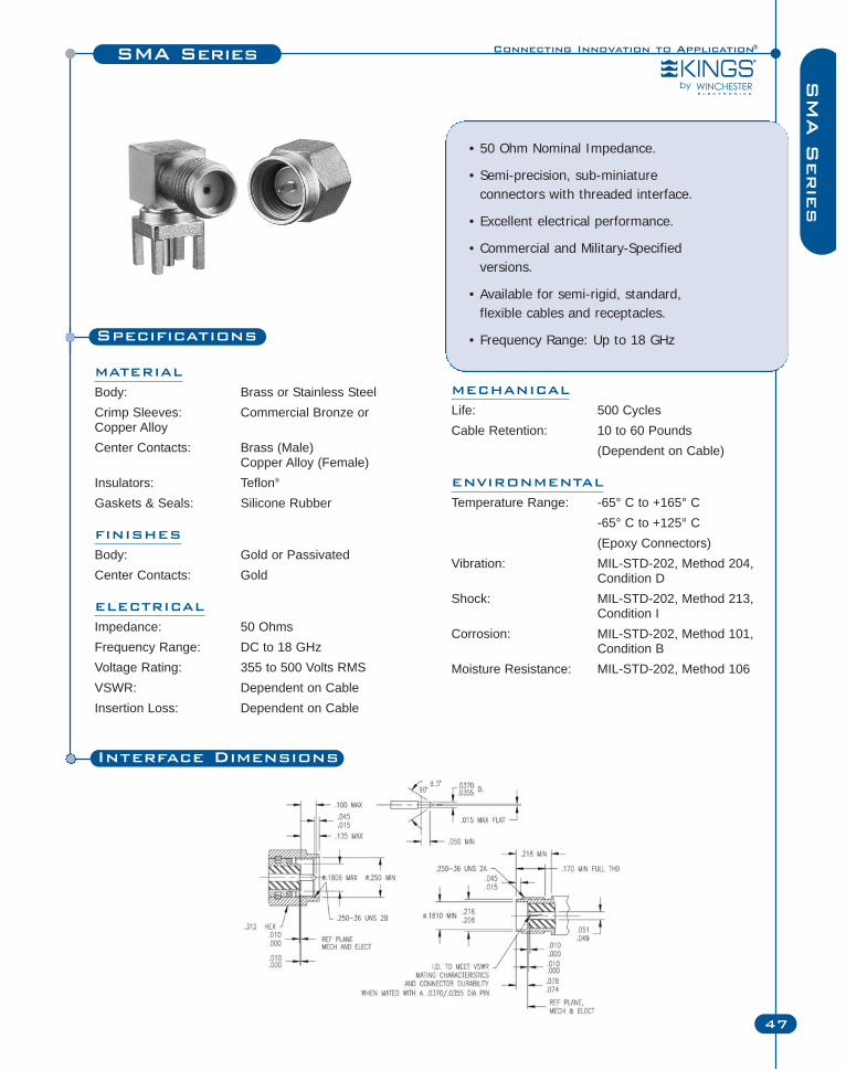
Specifications
MATERIAL
Body: Brass or Stainless SteelCrimp Sleeves: Commercial Bronze orCopper AlloyCenter Contacts: Brass (Male)
Copper Alloy (Female)Insulators: Teflon®
Gaskets & Seals: Silicone Rubber
FINISHES
Body: Gold or PassivatedCenter Contacts: Gold
ELECTRICAL
Impedance: 50 OhmsFrequency Range: DC to 18 GHzVoltage Rating: 355 to 500 Volts RMSVSWR: Dependent on CableInsertion Loss: Dependent on Cable
• 50 Ohm Nominal Impedance.
• Semi-precision, sub-miniature connectors with threaded interface.
• Excellent electrical performance.
• Commercial and Military-Specified versions.
• Available for semi-rigid, standard, flexible cables and receptacles.
• Frequency Range: Up to 18 GHz
Connecting Innovation to Application®SMA Series
47
SM
A S
erie
s
MECHANICAL
Life: 500 CyclesCable Retention: 10 to 60 Pounds
(Dependent on Cable)
ENVIRONMENTAL
Temperature Range: -65° C to +165° C -65° C to +125° C (Epoxy Connectors)
Vibration: MIL-STD-202, Method 204, Condition D
Shock: MIL-STD-202, Method 213, Condition I
Corrosion: MIL-STD-202, Method 101, Condition B
Moisture Resistance: MIL-STD-202, Method 106
Interface Dimensions
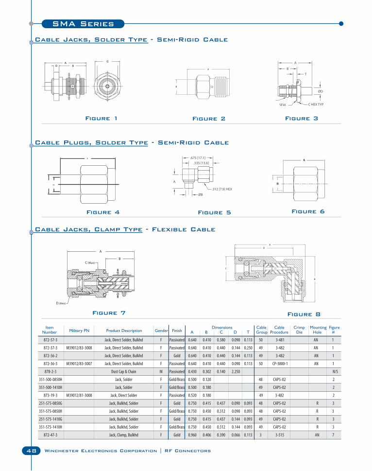
SMA Series
48 Winchester Electronics Corporation | RF Connectors
Figure 2 Figure 3
Figure 7
Figure 4
Figure 8
Figure 5
Item Dimensions Cable Cable Crimp Mounting FigureNumber Military PN Product Description Gender Finish A B C D T Group Procedure Die Hole #
872-57-3 Jack, Direct Solder, Bulkhd F Passivated 0.640 0.410 0.380 0.090 0.113 50 3-481 AN 1
872-37-3 M39012/83-3008 Jack, Direct Solder, Bulkhd F Passivated 0.640 0.410 0.440 0.144 0.250 49 3-482 AN 1
872-56-2 Jack, Direct Solder, Bulkhd F Gold 0.640 0.410 0.440 0.144 0.113 49 3-482 AN 1
872-36-3 M39012/83-3007 Jack, Direct Solder, Bulkhd F Passivated 0.640 0.410 0.440 0.090 0.113 50 CP-3800-1 AN 1
878-2-3 Dust Cap & Chain M Passivated 0.430 0.302 0.140 2.250 N/S
351-500-0850H Jack, Solder F Gold/Brass 0.500 0.120 48 CAP5-02 2
351-500-1410H Jack, Solder F Gold/Brass 0.500 0.180 49 CAP5-02 2
873-19-3 M39012/81-3008 Jack, Direct Solder F Passivated 0.520 0.180 49 3-482 2
251-575-0850G Jack, Bulkhd, Solder F Gold 0.750 0.415 0.437 0.090 0.093 48 CAP5-02 R 3
351-575-0850H Jack, Bulkhd, Solder F Gold/Brass 0.750 0.450 0.312 0.090 0.093 48 CAP5-02 R 3
251-575-1410G Jack, Bulkhd, Solder F Gold 0.750 0.415 0.437 0.144 0.093 49 CAP5-02 R 3
351-575-1410H Jack, Bulkhd, Solder F Gold/Brass 0.750 0.450 0.312 0.144 0.093 49 CAP5-02 R 3
872-47-3 Jack, Clamp, Bulkhd F Gold 0.960 0.406 0.390 0.066 0.113 3 3-515 AN 7
B
A
Cable Jacks, Clamp Type - Flexible Cable
Cable Plugs, Solder Type - Semi-Rigid Cable
Cable Jacks, Solder Type - Semi-Rigid Cable
Figure 1
Figure 6
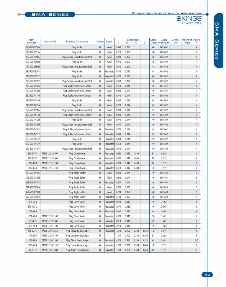
Connecting Innovation to Application®SMA Series
49
SM
A S
erie
s
Item Dimensions Cable Cable Crimp Mounting FigureNumber Military PN Product Description Gender Finish A B C D Group Procedure Die Hole #
250-500-0850G Plug, Solder M Gold 0.440 0.090 48 CAP5-02 4
250-500-0853G Plug, Solder M Gold 0.330 0.090 48 CAP5-02 4
250-500-0858G Plug, Solder, Insulator Assembled M Gold 0.440 0.090 48 CAP5-02 4
350-500-0850H Plug, Solder M Gold 0.440 0.090 48 CAP5-02 4
350-500-0858H Plug, Solder, Insulator Assembled M Gold 0.440 0.090 48 CAP5-02 4
250-500-0850P Plug, Solder M Passivated 0.440 0.090 48 CAP5-02 4
250-500-0853P Plug, Solder M Passivated 0.330 0.090 48 CAP5-02 4
250-500-0858P Plug, Solder, Insulator Assembled M Passivated 0.440 0.090 48 CAP5-02 4
250-500-1410G Plug, Solder, w/o Center Contact M Gold 0.330 0.144 49 CAP5-01 4
350-500-1410H Plug, Solder, w/o Center Contact M Gold 0.330 0.144 49 CAP5-01 4
250-500-1411G Plug, Solder, w/o Center Contact M Gold 0.440 0.144 49 CAP5-02 4
250-500-1412G Plug, Solder M Gold 0.440 0.144 49 CAP5-02 4
250-500-1413G Plug, Solder M Gold 0.330 0.144 49 CAP5-02 4
250-500-1418G Plug, Solder, Insulator Assembled M Gold 0.440 0.144 49 CAP5-02 4
350-500-1411H Plug, Solder, w/o Center Contact M Gold 0.440 0.144 49 CAP5-02 4
350-500-1412H Plug, Solder M Gold 0.440 0.144 49 CAP5-02 4
350-500-1418H Plug, Solder, Insulator Assembled M Gold 0.440 0.144 49 CAP5-02 4
250-500-1410P Plug, Solder, w/o Center Contact M Passivated 0.330 0.144 49 CAP5-01 4
250-500-1411P Plug, Solder, w/o Center Contact M Passivated 0.440 0.144 49 CAP5-02 4
250-500-1412P Plug, Solder M Passivated 0.440 0.144 49 CAP5-02 4
250-500-1413P Plug, Solder M Passivated 0.330 0.144 49 CAP5-02 4
250-500-1418P Plug, Solder, Insulator Assembled M Passivated 0.440 0.144 49 CAP5-02 4
875-81-17 M39012/55-3007 Plug, Conventional M Passivated 0.990 0.312 0.400 B1 3-559 4
875-82-17 M39012/55-3009 Plug, Conventional M Passivated 0.990 0.312 0.400 DE 3-519 4
875-82-3 M39012/55-3109 Plug, Conventional M Passivated 0.990 0.312 0.400 DE 3-519 4
875-86-3 M39012/55-3130 Plug, Conventional M Passivated 0.990 0.312 0.400 3 3-519 4
252-500-1410G Plug, Angle, Solder M Gold 0.310 0.144 49 CAP5-03 5
352-500-1410H Plug, Angle, Solder M Gold 0.310 0.144 49 CAP5-03 5
252-500-1410P Plug, Angle, Solder M Passivated 0.310 0.144 49 CAP5-03 5
252-500-0850G Plug, Angle, Solder M Gold 0.310 0.090 48 CAP5-03 5
352-500-0850H Plug, Angle, Solder M Gold 0.310 0.090 48 CAP5-03 5
252-500-0850P Plug, Angle, Solder M Passivated 0.310 0.090 48 CAP5-03 5
875-59-3 Plug, Direct Solder M Passivated 0.440 0.312 49 3-302 6
875-107-3 Plug, Direct Solder M Passivated 0.440 0.312 49 3-303 6
875-58-3 Plug, Direct Solder M Passivated 0.440 0.312 49 3-303 6
875-69-3 M39012/79-3107 Plug, Direct Solder M Passivated 0.430 0.310 50 3-481 6
875-70-17 M39012/79-3008 Plug, Direct Solder M Passivated 0.430 0.310 49 3-482 6
875-70-3 M39012/79-3108 Plug, Direct Solder M Passivated 0.430 0.310 49 3-482 6
876-62-17 M39012/56-3030 Plug, Conventional, Angle M Passivated 1.040 0.700 0.380 0.860 3 3-519 8
876-60-3 M39012/56-3107 Plug, Conventional, Angle M 1.040 0.700 0.380 0.860 B1 3-559 8
876-49-3 M39012/80-3108 Plug, Direct Solder, Angle M Passivated 0.650 0.540 0.180 0.510 49 3-482 N/S
876-62-3 M39012/56-3130 Plug, Conventional, Angle M Passivated 1.040 0.700 0.380 0.860 3 3-519 8
876-61-17 M39012/56-3009 Plug, Angle, Conventional M Passivated 1.040 0.700 0.380 0.860 DE 3-519 8
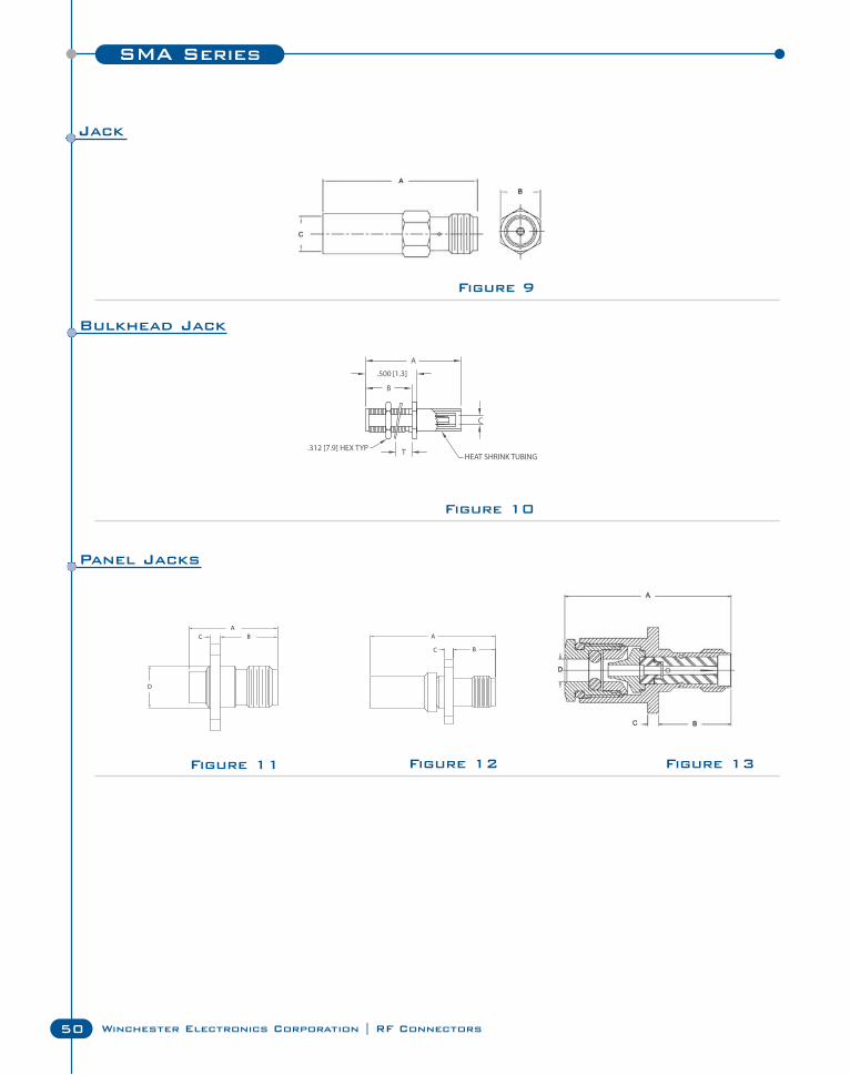
SMA Series
50 Winchester Electronics Corporation | RF Connectors
Figure 12
Figure 10
Figure 11 Figure 13
Figure 9
Jack
Bulkhead Jack
Panel Jacks
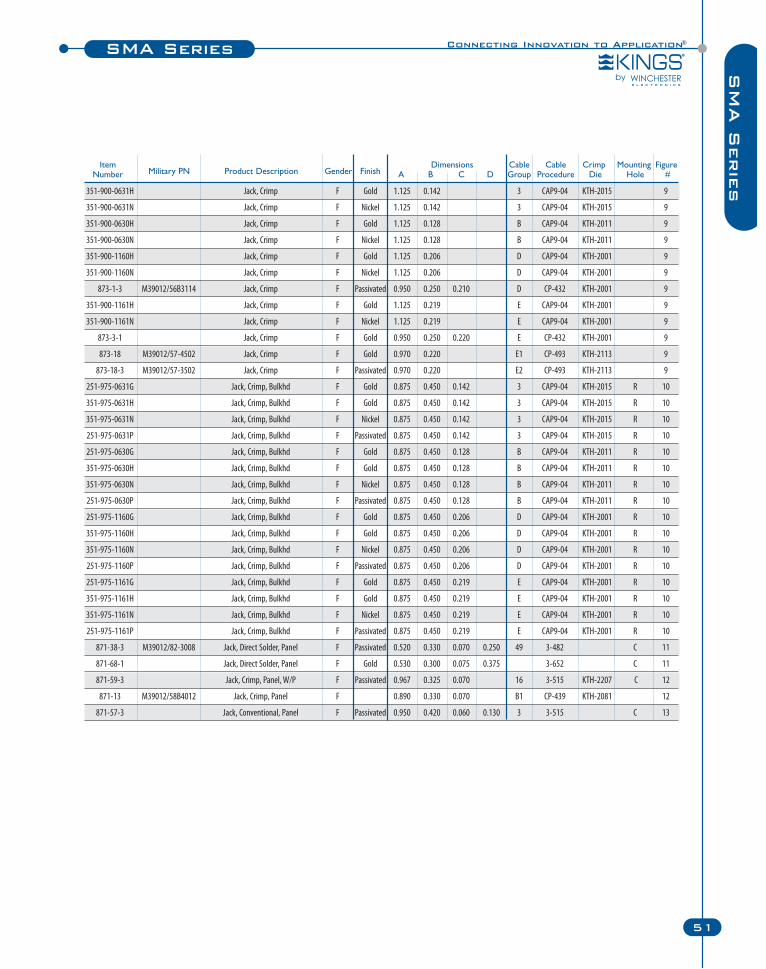
Connecting Innovation to Application®SMA Series
51
SM
A S
erie
s
Item Dimensions Cable Cable Crimp Mounting FigureNumber Military PN Product Description Gender Finish A B C D Group Procedure Die Hole #
351-900-0631H Jack, Crimp F Gold 1.125 0.142 3 CAP9-04 KTH-2015 9
351-900-0631N Jack, Crimp F Nickel 1.125 0.142 3 CAP9-04 KTH-2015 9
351-900-0630H Jack, Crimp F Gold 1.125 0.128 B CAP9-04 KTH-2011 9
351-900-0630N Jack, Crimp F Nickel 1.125 0.128 B CAP9-04 KTH-2011 9
351-900-1160H Jack, Crimp F Gold 1.125 0.206 D CAP9-04 KTH-2001 9
351-900-1160N Jack, Crimp F Nickel 1.125 0.206 D CAP9-04 KTH-2001 9
873-1-3 M39012/56B3114 Jack, Crimp F Passivated 0.950 0.250 0.210 D CP-432 KTH-2001 9
351-900-1161H Jack, Crimp F Gold 1.125 0.219 E CAP9-04 KTH-2001 9
351-900-1161N Jack, Crimp F Nickel 1.125 0.219 E CAP9-04 KTH-2001 9
873-3-1 Jack, Crimp F Gold 0.950 0.250 0.220 E CP-432 KTH-2001 9
873-18 M39012/57-4502 Jack, Crimp F Gold 0.970 0.220 E1 CP-493 KTH-2113 9
873-18-3 M39012/57-3502 Jack, Crimp F Passivated 0.970 0.220 E2 CP-493 KTH-2113 9
251-975-0631G Jack, Crimp, Bulkhd F Gold 0.875 0.450 0.142 3 CAP9-04 KTH-2015 R 10
351-975-0631H Jack, Crimp, Bulkhd F Gold 0.875 0.450 0.142 3 CAP9-04 KTH-2015 R 10
351-975-0631N Jack, Crimp, Bulkhd F Nickel 0.875 0.450 0.142 3 CAP9-04 KTH-2015 R 10
251-975-0631P Jack, Crimp, Bulkhd F Passivated 0.875 0.450 0.142 3 CAP9-04 KTH-2015 R 10
251-975-0630G Jack, Crimp, Bulkhd F Gold 0.875 0.450 0.128 B CAP9-04 KTH-2011 R 10
351-975-0630H Jack, Crimp, Bulkhd F Gold 0.875 0.450 0.128 B CAP9-04 KTH-2011 R 10
351-975-0630N Jack, Crimp, Bulkhd F Nickel 0.875 0.450 0.128 B CAP9-04 KTH-2011 R 10
251-975-0630P Jack, Crimp, Bulkhd F Passivated 0.875 0.450 0.128 B CAP9-04 KTH-2011 R 10
251-975-1160G Jack, Crimp, Bulkhd F Gold 0.875 0.450 0.206 D CAP9-04 KTH-2001 R 10
351-975-1160H Jack, Crimp, Bulkhd F Gold 0.875 0.450 0.206 D CAP9-04 KTH-2001 R 10
351-975-1160N Jack, Crimp, Bulkhd F Nickel 0.875 0.450 0.206 D CAP9-04 KTH-2001 R 10
251-975-1160P Jack, Crimp, Bulkhd F Passivated 0.875 0.450 0.206 D CAP9-04 KTH-2001 R 10
251-975-1161G Jack, Crimp, Bulkhd F Gold 0.875 0.450 0.219 E CAP9-04 KTH-2001 R 10
351-975-1161H Jack, Crimp, Bulkhd F Gold 0.875 0.450 0.219 E CAP9-04 KTH-2001 R 10
351-975-1161N Jack, Crimp, Bulkhd F Nickel 0.875 0.450 0.219 E CAP9-04 KTH-2001 R 10
251-975-1161P Jack, Crimp, Bulkhd F Passivated 0.875 0.450 0.219 E CAP9-04 KTH-2001 R 10
871-38-3 M39012/82-3008 Jack, Direct Solder, Panel F Passivated 0.520 0.330 0.070 0.250 49 3-482 C 11
871-68-1 Jack, Direct Solder, Panel F Gold 0.530 0.300 0.075 0.375 3-652 C 11
871-59-3 Jack, Crimp, Panel, W/P F Passivated 0.967 0.325 0.070 16 3-515 KTH-2207 C 12
871-13 M39012/58B4012 Jack, Crimp, Panel F 0.890 0.330 0.070 B1 CP-439 KTH-2081 12
871-57-3 Jack, Conventional, Panel F Passivated 0.950 0.420 0.060 0.130 3 3-515 C 13
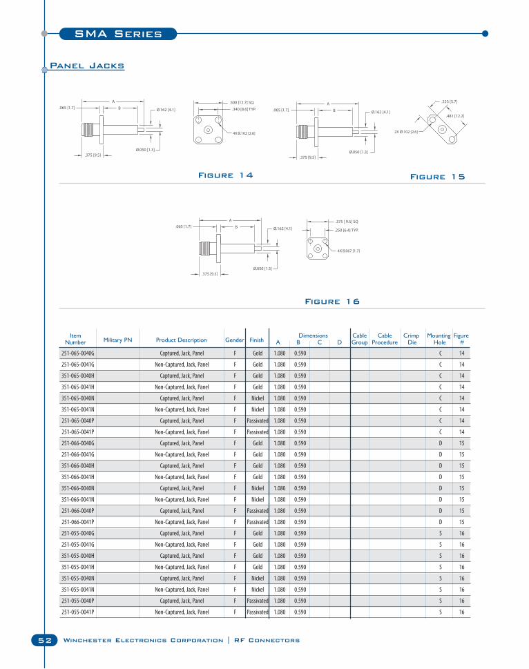
SMA Series
52 Winchester Electronics Corporation | RF Connectors
Figure 14 Figure 15
Figure 16
Item Dimensions Cable Cable Crimp Mounting FigureNumber Military PN Product Description Gender Finish A B C D Group Procedure Die Hole #
251-065-0040G Captured, Jack, Panel F Gold 1.080 0.590 C 14
251-065-0041G Non-Captured, Jack, Panel F Gold 1.080 0.590 C 14
351-065-0040H Captured, Jack, Panel F Gold 1.080 0.590 C 14
351-065-0041H Non-Captured, Jack, Panel F Gold 1.080 0.590 C 14
351-065-0040N Captured, Jack, Panel F Nickel 1.080 0.590 C 14
351-065-0041N Non-Captured, Jack, Panel F Nickel 1.080 0.590 C 14
251-065-0040P Captured, Jack, Panel F Passivated 1.080 0.590 C 14
251-065-0041P Non-Captured, Jack, Panel F Passivated 1.080 0.590 C 14
251-066-0040G Captured, Jack, Panel F Gold 1.080 0.590 D 15
251-066-0041G Non-Captured, Jack, Panel F Gold 1.080 0.590 D 15
351-066-0040H Captured, Jack, Panel F Gold 1.080 0.590 D 15
351-066-0041H Non-Captured, Jack, Panel F Gold 1.080 0.590 D 15
351-066-0040N Captured, Jack, Panel F Nickel 1.080 0.590 D 15
351-066-0041N Non-Captured, Jack, Panel F Nickel 1.080 0.590 D 15
251-066-0040P Captured, Jack, Panel F Passivated 1.080 0.590 D 15
251-066-0041P Non-Captured, Jack, Panel F Passivated 1.080 0.590 D 15
251-055-0040G Captured, Jack, Panel F Gold 1.080 0.590 S 16
251-055-0041G Non-Captured, Jack, Panel F Gold 1.080 0.590 S 16
351-055-0040H Captured, Jack, Panel F Gold 1.080 0.590 S 16
351-055-0041H Non-Captured, Jack, Panel F Gold 1.080 0.590 S 16
351-055-0040N Captured, Jack, Panel F Nickel 1.080 0.590 S 16
351-055-0041N Non-Captured, Jack, Panel F Nickel 1.080 0.590 S 16
251-055-0040P Captured, Jack, Panel F Passivated 1.080 0.590 S 16
251-055-0041P Non-Captured, Jack, Panel F Passivated 1.080 0.590 S 16
Panel Jacks
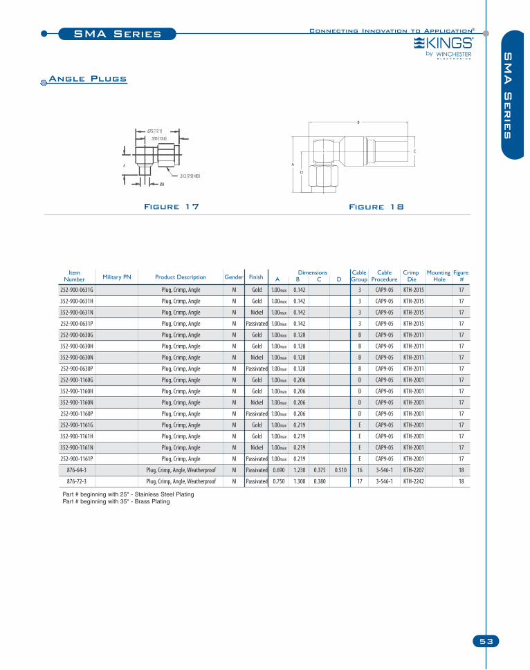
Connecting Innovation to Application®SMA Series
53
SM
A S
erie
s
Figure 17 Figure 18
Item Dimensions Cable Cable Crimp Mounting FigureNumber Military PN Product Description Gender Finish A B C D Group Procedure Die Hole #
252-900-0631G Plug, Crimp, Angle M Gold 1.00max 0.142 3 CAP9-05 KTH-2015 17
352-900-0631H Plug, Crimp, Angle M Gold 1.00max 0.142 3 CAP9-05 KTH-2015 17
352-900-0631N Plug, Crimp, Angle M Nickel 1.00max 0.142 3 CAP9-05 KTH-2015 17
252-900-0631P Plug, Crimp, Angle M Passivated 1.00max 0.142 3 CAP9-05 KTH-2015 17
252-900-0630G Plug, Crimp, Angle M Gold 1.00max 0.128 B CAP9-05 KTH-2011 17
352-900-0630H Plug, Crimp, Angle M Gold 1.00max 0.128 B CAP9-05 KTH-2011 17
352-900-0630N Plug, Crimp, Angle M Nickel 1.00max 0.128 B CAP9-05 KTH-2011 17
252-900-0630P Plug, Crimp, Angle M Passivated 1.00max 0.128 B CAP9-05 KTH-2011 17
252-900-1160G Plug, Crimp, Angle M Gold 1.00max 0.206 D CAP9-05 KTH-2001 17
352-900-1160H Plug, Crimp, Angle M Gold 1.00max 0.206 D CAP9-05 KTH-2001 17
352-900-1160N Plug, Crimp, Angle M Nickel 1.00max 0.206 D CAP9-05 KTH-2001 17
252-900-1160P Plug, Crimp, Angle M Passivated 1.00max 0.206 D CAP9-05 KTH-2001 17
252-900-1161G Plug, Crimp, Angle M Gold 1.00max 0.219 E CAP9-05 KTH-2001 17
352-900-1161H Plug, Crimp, Angle M Gold 1.00max 0.219 E CAP9-05 KTH-2001 17
352-900-1161N Plug, Crimp, Angle M Nickel 1.00max 0.219 E CAP9-05 KTH-2001 17
252-900-1161P Plug, Crimp, Angle M Passivated 1.00max 0.219 E CAP9-05 KTH-2001 17
876-64-3 Plug, Crimp, Angle, Weatherproof M Passivated 0.690 1.230 0.375 0.510 16 3-546-1 KTH-2207 18
876-72-3 Plug, Crimp, Angle, Weatherproof M Passivated 0.750 1.300 0.380 17 3-546-1 KTH-2242 18
.535 [13.6]
.675 [17.1]
A
.312 [7.9] HEX
ØB
Angle Plugs
Part # beginning with 25* - Stainless Steel PlatingPart # beginning with 35* - Brass Plating
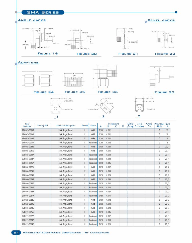
SMA Series
54 Winchester Electronics Corporation | RF Connectors
Figure 20Figure 19 Figure 21 Figure 22
Figure 24 Figure 23
Item Dimensions Cable Cable Crimp Mounting FigureNumber Military PN Product Description Gender Finish A B C D Group Procedure Die Hole #
253-065-0000G Jack, Angle, Panel F Gold 0.200 0.062 C 19
353-065-0000H Jack, Angle, Panel F Gold 0.200 0.062 C 19
353-065-0000N Jack, Angle, Panel F Nickel 0.200 0.062 C 19
253-065-0000P Jack, Angle, Panel F Passivated 0.200 0.062 C 19
253-065-0024G Jack, Angle, Panel F Gold 0.050 0.028 C 20_1
253-065-0025G Jack, Angle, Panel F Gold 0.050 0.036 C 20_1
253-065-0023P Jack, Angle, Panel F Passivated 0.050 0.018 C 20_1
253-065-0024P Jack, Angle, Panel F Passivated 0.050 0.028 C 20_1
253-065-0025P Jack, Angle, Panel F Passivated 0.050 0.036 C 20_1
253-066-0022G Jack, Angle, Panel F Gold 0.050 0.012 D 20_2
253-066-0023G Jack, Angle, Panel F Gold 0.050 0.018 D 20_2
253-066-0024G Jack, Angle, Panel F Gold 0.050 0.028 D 20_2
253-066-0025G Jack, Angle, Panel F Gold 0.050 0.036 D 20_2
253-066-0022P Jack, Angle, Panel F Passivated 0.050 0.012 D 20_2
253-066-0023P Jack, Angle, Panel F Passivated 0.050 0.018 D 20_2
253-066-0024P Jack, Angle, Panel F Passivated 0.050 0.028 D 20_2
253-066-0025P Jack, Angle, Panel F Passivated 0.050 0.036 D 20_2
253-055-0022G Jack, Angle, Panel F Gold 0.050 0.012 S 20_3
253-055-0023G Jack, Angle, Panel F Gold 0.050 0.018 S 20_3
253-055-0024G Jack, Angle, Panel F Gold 0.050 0.028 S 20_3
253-055-0025G Jack, Angle, Panel F Gold 0.050 0.036 S 20_3
253-055-0022P Jack, Angle, Panel F Passivated 0.050 0.012 S 20_3
253-055-0023P Jack, Angle, Panel F Passivated 0.050 0.018 S 20_3
253-055-0024P Jack, Angle, Panel F Passivated 0.050 0.028 S 20_3
_1 _2 _3
Figure 25 Figure 26
Angle Jacks Panel Jacks
Adapters
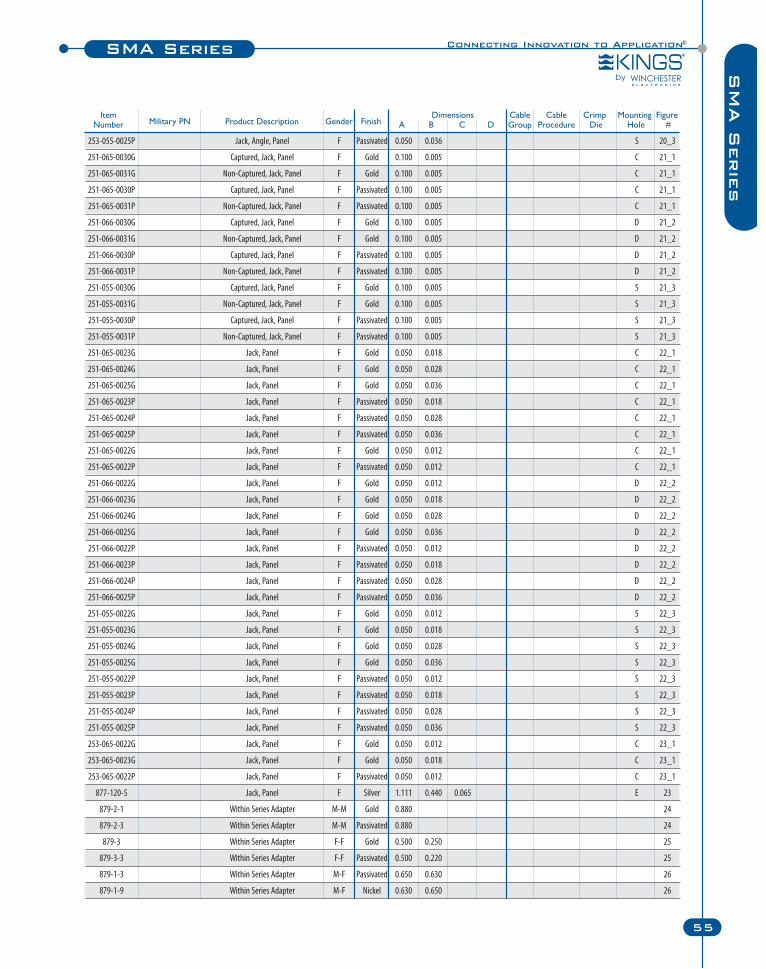
Connecting Innovation to Application®SMA Series
55
SM
A S
erie
s
Item Dimensions Cable Cable Crimp Mounting FigureNumber Military PN Product Description Gender Finish A B C D Group Procedure Die Hole #
253-055-0025P Jack, Angle, Panel F Passivated 0.050 0.036 S 20_3
251-065-0030G Captured, Jack, Panel F Gold 0.100 0.005 C 21_1
251-065-0031G Non-Captured, Jack, Panel F Gold 0.100 0.005 C 21_1
251-065-0030P Captured, Jack, Panel F Passivated 0.100 0.005 C 21_1
251-065-0031P Non-Captured, Jack, Panel F Passivated 0.100 0.005 C 21_1
251-066-0030G Captured, Jack, Panel F Gold 0.100 0.005 D 21_2
251-066-0031G Non-Captured, Jack, Panel F Gold 0.100 0.005 D 21_2
251-066-0030P Captured, Jack, Panel F Passivated 0.100 0.005 D 21_2
251-066-0031P Non-Captured, Jack, Panel F Passivated 0.100 0.005 D 21_2
251-055-0030G Captured, Jack, Panel F Gold 0.100 0.005 S 21_3
251-055-0031G Non-Captured, Jack, Panel F Gold 0.100 0.005 S 21_3
251-055-0030P Captured, Jack, Panel F Passivated 0.100 0.005 S 21_3
251-055-0031P Non-Captured, Jack, Panel F Passivated 0.100 0.005 S 21_3
251-065-0023G Jack, Panel F Gold 0.050 0.018 C 22_1
251-065-0024G Jack, Panel F Gold 0.050 0.028 C 22_1
251-065-0025G Jack, Panel F Gold 0.050 0.036 C 22_1
251-065-0023P Jack, Panel F Passivated 0.050 0.018 C 22_1
251-065-0024P Jack, Panel F Passivated 0.050 0.028 C 22_1
251-065-0025P Jack, Panel F Passivated 0.050 0.036 C 22_1
251-065-0022G Jack, Panel F Gold 0.050 0.012 C 22_1
251-065-0022P Jack, Panel F Passivated 0.050 0.012 C 22_1
251-066-0022G Jack, Panel F Gold 0.050 0.012 D 22_2
251-066-0023G Jack, Panel F Gold 0.050 0.018 D 22_2
251-066-0024G Jack, Panel F Gold 0.050 0.028 D 22_2
251-066-0025G Jack, Panel F Gold 0.050 0.036 D 22_2
251-066-0022P Jack, Panel F Passivated 0.050 0.012 D 22_2
251-066-0023P Jack, Panel F Passivated 0.050 0.018 D 22_2
251-066-0024P Jack, Panel F Passivated 0.050 0.028 D 22_2
251-066-0025P Jack, Panel F Passivated 0.050 0.036 D 22_2
251-055-0022G Jack, Panel F Gold 0.050 0.012 S 22_3
251-055-0023G Jack, Panel F Gold 0.050 0.018 S 22_3
251-055-0024G Jack, Panel F Gold 0.050 0.028 S 22_3
251-055-0025G Jack, Panel F Gold 0.050 0.036 S 22_3
251-055-0022P Jack, Panel F Passivated 0.050 0.012 S 22_3
251-055-0023P Jack, Panel F Passivated 0.050 0.018 S 22_3
251-055-0024P Jack, Panel F Passivated 0.050 0.028 S 22_3
251-055-0025P Jack, Panel F Passivated 0.050 0.036 S 22_3
253-065-0022G Jack, Panel F Gold 0.050 0.012 C 23_1
253-065-0023G Jack, Panel F Gold 0.050 0.018 C 23_1
253-065-0022P Jack, Panel F Passivated 0.050 0.012 C 23_1
877-120-5 Jack, Panel F Silver 1.111 0.440 0.065 E 23
879-2-1 Within Series Adapter M-M Gold 0.880 24
879-2-3 Within Series Adapter M-M Passivated 0.880 24
879-3 Within Series Adapter F-F Gold 0.500 0.250 25
879-3-3 Within Series Adapter F-F Passivated 0.500 0.220 25
879-1-3 Within Series Adapter M-F Passivated 0.650 0.630 26
879-1-9 Within Series Adapter M-F Nickel 0.630 0.650 26
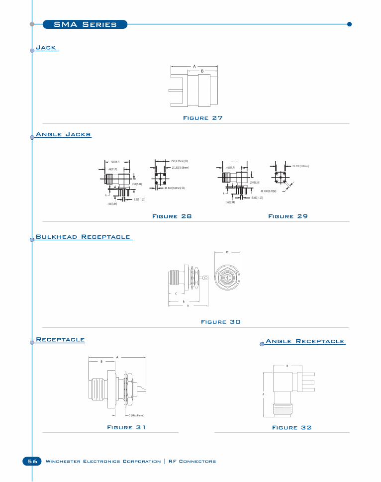
SMA Series
56 Winchester Electronics Corporation | RF Connectors
Figure 28 Figure 29
Figure 30
Figure 31 Figure 32
Figure 27
Ø.050 [1.27].155 [3.94]
.46 [11.7]
.58 [14.7]
2X .200 [5.08mm]
.250 [6.35mm] SQ.
4X .040 [1.02mm] SQ.
A
.250 [6.35]
Ø.050 [1.27].155 [3.94]
.46 [11.7]
.58 [14.7]
2X .200 [5.08mm]
A4X .030 [0.76]SQ
.250 [6.35]
Jack
Angle Jacks
Bulkhead Receptacle
Receptacle Angle Receptacle
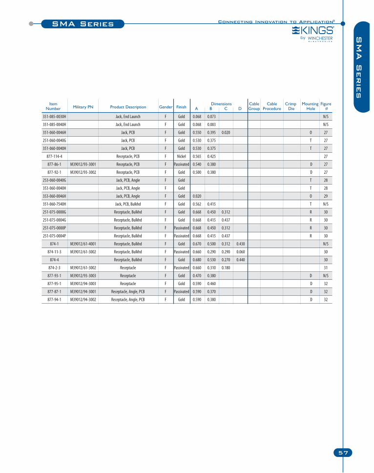
Connecting Innovation to Application®SMA Series
57
SM
A S
erie
s
351-085-0030H Jack, End Launch F Gold 0.068 0.073 N/S
351-085-0040H Jack, End Launch F Gold 0.068 0.083 N/S
351-060-0046H Jack, PCB F Gold 0.550 0.395 0.020 O 27
251-060-0040G Jack, PCB F Gold 0.530 0.375 T 27
351-060-0040H Jack, PCB F Gold 0.530 0.375 T 27
877-114-4 Receptacle, PCB F Nickel 0.565 0.425 27
877-86-1 M39012/93-3001 Receptacle, PCB F Passivated 0.540 0.380 D 27
877-92-1 M39012/93-3002 Receptacle, PCB F Gold 0.500 0.380 D 27
253-060-0040G Jack, PCB, Angle F Gold T 28
353-060-0040H Jack, PCB, Angle F Gold T 28
353-060-0046H Jack, PCB, Angle F Gold 0.020 O 29
351-060-7540H Jack, PCB, Bulkhd F Gold 0.562 0.415 T N/S
251-075-0000G Receptacle, Bulkhd F Gold 0.668 0.450 0.312 R 30
251-075-0004G Receptacle, Bulkhd F Gold 0.668 0.415 0.437 R 30
251-075-0000P Receptacle, Bulkhd F Passivated 0.668 0.450 0.312 R 30
251-075-0004P Receptacle, Bulkhd F Passivated 0.668 0.415 0.437 R 30
874-1 M39012/61-4001 Receptacle, Bulkhd F Gold 0.670 0.500 0.312 0.430 N/S
874-11-3 M39012/61-3002 Receptacle, Bulkhd F Passivated 0.660 0.290 0.290 0.060 30
874-4 Receptacle, Bulkhd F Gold 0.680 0.530 0.270 0.440 30
874-2-3 M39012/61-3002 Receptacle F Passivated 0.660 0.310 0.180 31
877-93-1 M39012/93-3003 Receptacle F Gold 0.470 0.380 D N/S
877-95-1 M39012/94-3003 Receptacle F Gold 0.590 0.460 D 32
877-87-1 M39012/94-3001 Receptacle, Angle, PCB F Passivated 0.590 0.370 D 32
877-94-1 M39012/94-3002 Receptacle, Angle, PCB F Gold 0.590 0.380 D 32
Item Dimensions Cable Cable Crimp Mounting FigureNumber Military PN Product Description Gender Finish A B C D Group Procedure Die Hole #
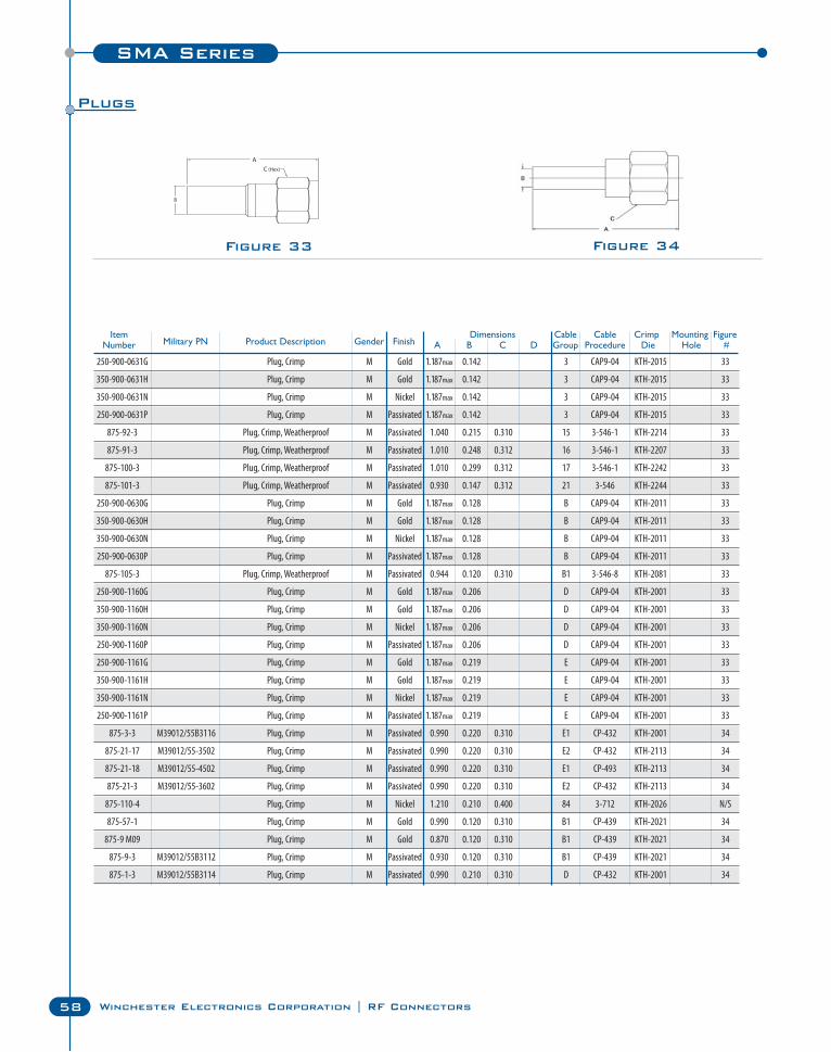
SMA Series
58 Winchester Electronics Corporation | RF Connectors
Figure 33
Item Dimensions Cable Cable Crimp Mounting FigureNumber Military PN Product Description Gender Finish A B C D Group Procedure Die Hole #
250-900-0631G Plug, Crimp M Gold 1.187max 0.142 3 CAP9-04 KTH-2015 33
350-900-0631H Plug, Crimp M Gold 1.187max 0.142 3 CAP9-04 KTH-2015 33
350-900-0631N Plug, Crimp M Nickel 1.187max 0.142 3 CAP9-04 KTH-2015 33
250-900-0631P Plug, Crimp M Passivated 1.187max 0.142 3 CAP9-04 KTH-2015 33
875-92-3 Plug, Crimp, Weatherproof M Passivated 1.040 0.215 0.310 15 3-546-1 KTH-2214 33
875-91-3 Plug, Crimp, Weatherproof M Passivated 1.010 0.248 0.312 16 3-546-1 KTH-2207 33
875-100-3 Plug, Crimp, Weatherproof M Passivated 1.010 0.299 0.312 17 3-546-1 KTH-2242 33
875-101-3 Plug, Crimp, Weatherproof M Passivated 0.930 0.147 0.312 21 3-546 KTH-2244 33
250-900-0630G Plug, Crimp M Gold 1.187max 0.128 B CAP9-04 KTH-2011 33
350-900-0630H Plug, Crimp M Gold 1.187max 0.128 B CAP9-04 KTH-2011 33
350-900-0630N Plug, Crimp M Nickel 1.187max 0.128 B CAP9-04 KTH-2011 33
250-900-0630P Plug, Crimp M Passivated 1.187max 0.128 B CAP9-04 KTH-2011 33
875-105-3 Plug, Crimp, Weatherproof M Passivated 0.944 0.120 0.310 B1 3-546-8 KTH-2081 33
250-900-1160G Plug, Crimp M Gold 1.187max 0.206 D CAP9-04 KTH-2001 33
350-900-1160H Plug, Crimp M Gold 1.187max 0.206 D CAP9-04 KTH-2001 33
350-900-1160N Plug, Crimp M Nickel 1.187max 0.206 D CAP9-04 KTH-2001 33
250-900-1160P Plug, Crimp M Passivated 1.187max 0.206 D CAP9-04 KTH-2001 33
250-900-1161G Plug, Crimp M Gold 1.187max 0.219 E CAP9-04 KTH-2001 33
350-900-1161H Plug, Crimp M Gold 1.187max 0.219 E CAP9-04 KTH-2001 33
350-900-1161N Plug, Crimp M Nickel 1.187max 0.219 E CAP9-04 KTH-2001 33
250-900-1161P Plug, Crimp M Passivated 1.187max 0.219 E CAP9-04 KTH-2001 33
875-3-3 M39012/55B3116 Plug, Crimp M Passivated 0.990 0.220 0.310 E1 CP-432 KTH-2001 34
875-21-17 M39012/55-3502 Plug, Crimp M Passivated 0.990 0.220 0.310 E2 CP-432 KTH-2113 34
875-21-18 M39012/55-4502 Plug, Crimp M Passivated 0.990 0.220 0.310 E1 CP-493 KTH-2113 34
875-21-3 M39012/55-3602 Plug, Crimp M Passivated 0.990 0.220 0.310 E2 CP-432 KTH-2113 34
875-110-4 Plug, Crimp M Nickel 1.210 0.210 0.400 84 3-712 KTH-2026 N/S
875-57-1 Plug, Crimp M Gold 0.990 0.120 0.310 B1 CP-439 KTH-2021 34
875-9 M09 Plug, Crimp M Gold 0.870 0.120 0.310 B1 CP-439 KTH-2021 34
875-9-3 M39012/55B3112 Plug, Crimp M Passivated 0.930 0.120 0.310 B1 CP-439 KTH-2021 34
875-1-3 M39012/55B3114 Plug, Crimp M Passivated 0.990 0.210 0.310 D CP-432 KTH-2001 34
Figure 34
Plugs
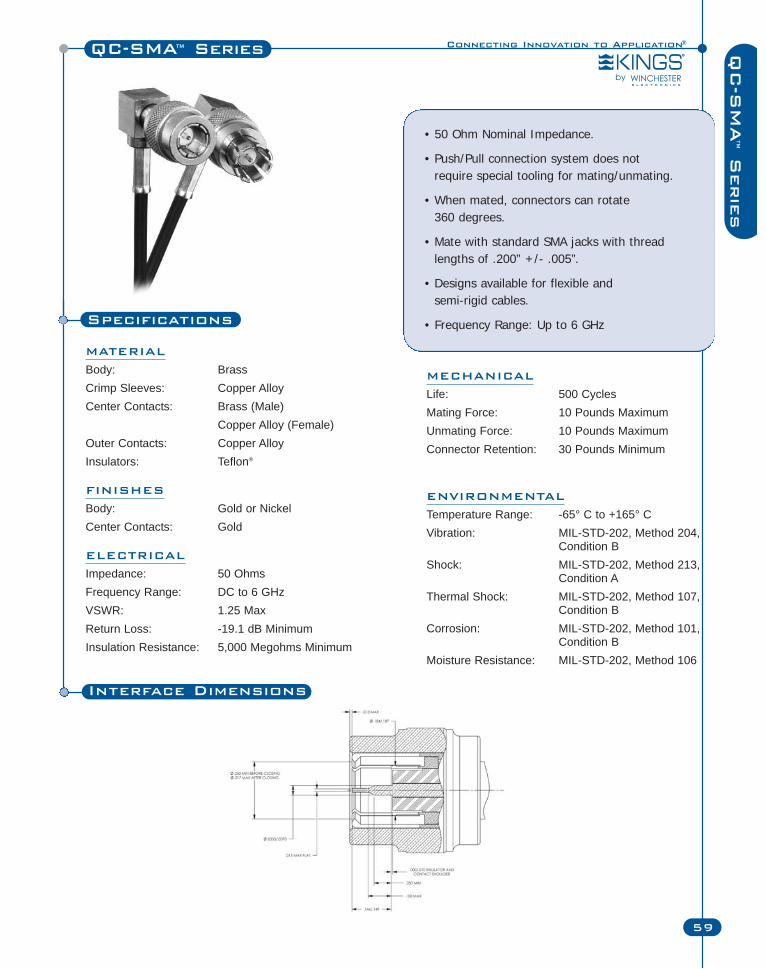
Specifications
MATERIAL
Body: BrassCrimp Sleeves: Copper AlloyCenter Contacts: Brass (Male)
Copper Alloy (Female)Outer Contacts: Copper AlloyInsulators: Teflon®
FINISHES
Body: Gold or NickelCenter Contacts: Gold
ELECTRICAL
Impedance: 50 OhmsFrequency Range: DC to 6 GHzVSWR: 1.25 MaxReturn Loss: -19.1 dB MinimumInsulation Resistance: 5,000 Megohms Minimum
Connecting Innovation to Application®QC-SMA™ Series
59
QC
-SM
A™
Serie
s
• 50 Ohm Nominal Impedance.
• Push/Pull connection system does not require special tooling for mating/unmating.
• When mated, connectors can rotate 360 degrees.
• Mate with standard SMA jacks with threadlengths of .200” +/- .005”.
• Designs available for flexible and semi-rigid cables.
• Frequency Range: Up to 6 GHz
MECHANICAL
Life: 500 CyclesMating Force: 10 Pounds MaximumUnmating Force: 10 Pounds MaximumConnector Retention: 30 Pounds Minimum
ENVIRONMENTAL
Temperature Range: -65° C to +165° CVibration: MIL-STD-202, Method 204,
Condition BShock: MIL-STD-202, Method 213,
Condition AThermal Shock: MIL-STD-202, Method 107,
Condition BCorrosion: MIL-STD-202, Method 101,
Condition BMoisture Resistance: MIL-STD-202, Method 106
Interface Dimensions
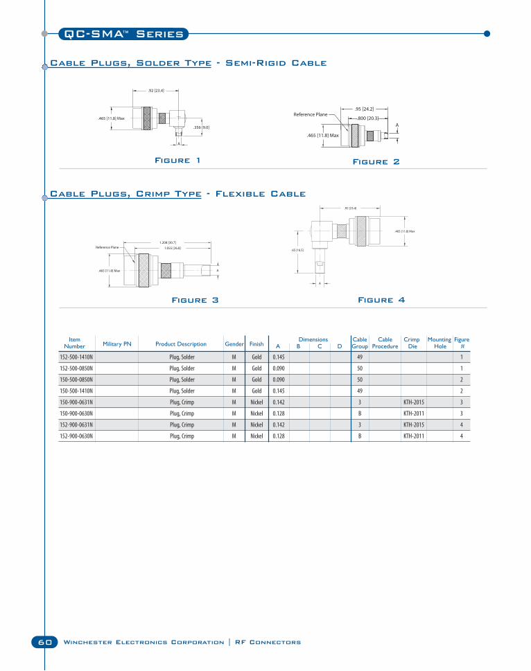
C Series
60 Winchester Electronics Corporation | RF Connectors
QC-SMA™ Series
Figure 2Figure 1
Figure 3 Figure 4
Item Dimensions Cable Cable Crimp Mounting FigureNumber Military PN Product Description Gender Finish A B C D Group Procedure Die Hole #
152-500-1410N Plug, Solder M Gold 0.145 49 1
152-500-0850N Plug, Solder M Gold 0.090 50 1
150-500-0850N Plug, Solder M Gold 0.090 50 2
150-500-1410N Plug, Solder M Gold 0.145 49 2
150-900-0631N Plug, Crimp M Nickel 0.142 3 KTH-2015 3
150-900-0630N Plug, Crimp M Nickel 0.128 B KTH-2011 3
152-900-0631N Plug, Crimp M Nickel 0.142 3 KTH-2015 4
152-900-0630N Plug, Crimp M Nickel 0.128 B KTH-2011 4
Cable Plugs, Crimp Type - Flexible Cable
Cable Plugs, Solder Type - Semi-Rigid Cable
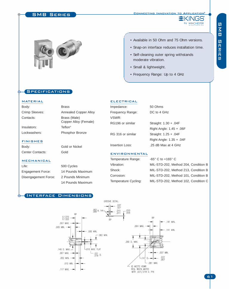
Connecting Innovation to Application®
61
SM
B S
erie
sSMB Series
Specifications
MATERIAL
Body: Brass
Crimp Sleeves: Annealed Copper Alloy
Contacts: Brass (Male)Copper Alloy (Female)
Insulators: Teflon®
Lockwashers: Phosphor Bronze
FINISHES
Body: Gold or Nickel
Center Contacts: Gold
MECHANICAL
Life: 500 Cycles
Engagement Force: 14 Pounds Maximum
Disengagement Force: 2 Pounds Minimum
14 Pounds Maximum
• Available in 50 Ohm and 75 Ohm versions.
• Snap-on interface reduces installation time.
• Self-cleaning outer spring withstands moderate vibration.
• Small & lightweight.
• Frequency Range: Up to 4 GHz
ELECTRICAL
Impedance: 50 Ohms
Frequency Range: DC to 4 GHz
VSWR:
RG196 or similar Straight: 1.30 + .04F
Right Angle: 1.45 + .06F
RG 316 or similar Straight: 1.25 + .04F
Right Angle: 1.35 + .04F
Insertion Loss: .25 dB Max at 4 GHz
ENVIRONMENTAL
Temperature Range: -65° C to +165° C
Vibration: MIL-STD-202, Method 204, Condition B
Shock: MIL-STD-202, Method 213, Condition B
Corrosion: MIL-STD-202, Method 101, Condition B
Temperature Cycling: MIL-STD-202, Method 102, Condition C
Interface Dimensions
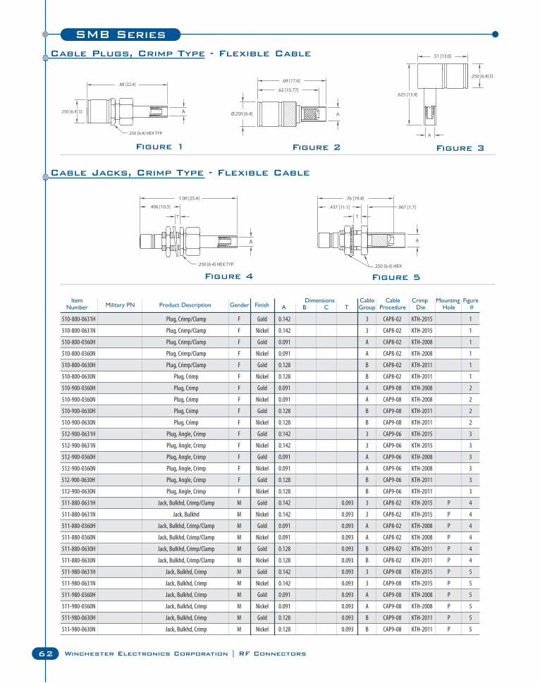
510-800-0631H Plug, Crimp/Clamp F Gold 0.142 3 CAP8-02 KTH-2015 1
510-800-0631N Plug, Crimp/Clamp F Nickel 0.142 3 CAP8-02 KTH-2015 1
510-800-0360H Plug, Crimp/Clamp F Gold 0.091 A CAP8-02 KTH-2008 1
510-800-0360N Plug, Crimp/Clamp F Nickel 0.091 A CAP8-02 KTH-2008 1
510-800-0630H Plug, Crimp/Clamp F Gold 0.128 B CAP8-02 KTH-2011 1
510-800-0630N Plug, Crimp F Nickel 0.128 B CAP8-02 KTH-2011 1
510-900-0360H Plug, Crimp F Gold 0.091 A CAP9-08 KTH-2008 2
510-900-0360N Plug, Crimp F Nickel 0.091 A CAP9-08 KTH-2008 2
510-900-0630H Plug, Crimp F Gold 0.128 B CAP9-08 KTH-2011 2
510-900-0630N Plug, Crimp F Nickel 0.128 B CAP9-08 KTH-2011 2
512-900-0631H Plug, Angle, Crimp F Gold 0.142 3 CAP9-06 KTH-2015 3
512-900-0631N Plug, Angle, Crimp F Nickel 0.142 3 CAP9-06 KTH-2015 3
512-900-0360H Plug, Angle, Crimp F Gold 0.091 A CAP9-06 KTH-2008 3
512-900-0360N Plug, Angle, Crimp F Nickel 0.091 A CAP9-06 KTH-2008 3
512-900-0630H Plug, Angle, Crimp F Gold 0.128 B CAP9-06 KTH-2011 3
512-900-0630N Plug, Angle, Crimp F Nickel 0.128 B CAP9-06 KTH-2011 3
511-880-0631H Jack, Bulkhd, Crimp/Clamp M Gold 0.142 0.093 3 CAP8-02 KTH-2015 P 4
511-880-0631N Jack, Bulkhd M Nickel 0.142 0.093 3 CAP8-02 KTH-2015 P 4
511-880-0360H Jack, Bulkhd, Crimp/Clamp M Gold 0.091 0.093 A CAP8-02 KTH-2008 P 4
511-880-0360N Jack, Bulkhd, Crimp/Clamp M Nickel 0.091 0.093 A CAP8-02 KTH-2008 P 4
511-880-0630H Jack, Bulkhd, Crimp/Clamp M Gold 0.128 0.093 B CAP8-02 KTH-2011 P 4
511-880-0630N Jack, Bulkhd, Crimp/Clamp M Nickel 0.128 0.093 B CAP8-02 KTH-2011 P 4
511-980-0631H Jack, Bulkhd, Crimp M Gold 0.142 0.093 3 CAP9-08 KTH-2015 P 5
511-980-0631N Jack, Bulkhd, Crimp M Nickel 0.142 0.093 3 CAP9-08 KTH-2015 P 5
511-980-0360H Jack, Bulkhd, Crimp M Gold 0.091 0.093 A CAP9-08 KTH-2008 P 5
511-980-0360N Jack, Bulkhd, Crimp M Nickel 0.091 0.093 A CAP9-08 KTH-2008 P 5
511-980-0630H Jack, Bulkhd, Crimp M Gold 0.128 0.093 B CAP9-08 KTH-2011 P 5
511-980-0630N Jack, Bulkhd, Crimp M Nickel 0.128 0.093 B CAP9-08 KTH-2011 P 5
SMB Series
62 Winchester Electronics Corporation | RF Connectors
Figure 4
Figure 3Figure 1
Figure 5
Figure 2
Item Dimensions Cable Cable Crimp Mounting FigureNumber Military PN Product Description Gender Finish A B C T Group Procedure Die Hole #
Cable Plugs, Crimp Type - Flexible Cable
Cable Jacks, Crimp Type - Flexible Cable
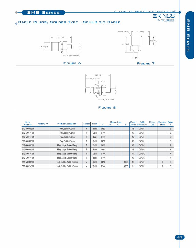
Figure 7
510-600-0850N Plug, Solder/Clamp F Nickel 0.090 48 CAP6-01 6
510-600-1410H Plug, Solder/Clamp F Gold 0.144 49 CAP6-01 6
510-600-1410N Plug, Solder/Clamp F Nickel 0.144 49 CAP6-01 6
510-600-0850H Plug, Solder/Clamp F Gold 0.090 48 CAP6-01 6
512-600-0850H Plug, Angle, Solder/Clamp F Gold 0.090 48 CAP6-02 7
512-600-0850N Plug, Angle, Solder/Clamp F Nickel 0.090 48 CAP6-02 7
512-600-1410H Plug, Angle, Solder/Clamp F Gold 0.144 49 CAP6-02 7
512-600-1410N Plug, Angle, Solder/Clamp F Nickel 0.144 49 CAP6-02 7
511-680-0850H Jack, Bulkhd, Solder/Clamp M Gold 0.090 0.093 48 CAP6-01 P 8
511-680-1410H Jack, Bulkhd, Solder/Clamp M Gold 0.144 0.093 B CAP6-01 P 8
Item Dimensions Cable Cable Crimp Mounting FigureNumber Military PN Product Description Gender Finish A B C T Group Procedure Die Hole #
Connecting Innovation to Application®SMB Series
63
SM
B S
erie
s
Figure 6
Figure 8
Cable Plugs, Solder Type - Semi-Rigid Cable
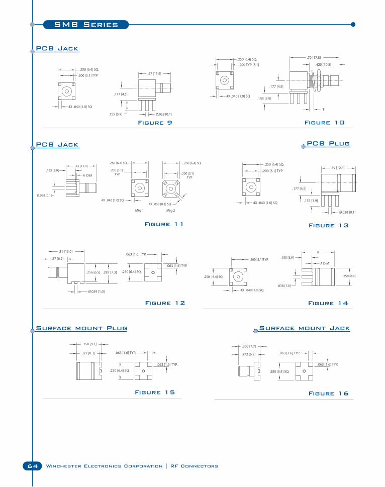
SMB Series
64 Winchester Electronics Corporation | RF Connectors
Figure 12
Figure 15 Figure 16
Figure 11
Figure 14
Figure 9
Figure 13
Figure 10
PCB Jack
PCB PlugPCB Jack
Surface mount JackSurface mount Plug
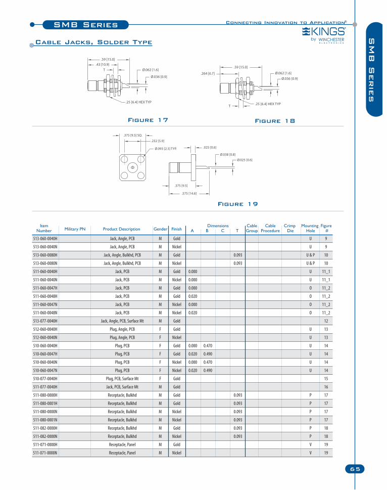
513-060-0040H Jack, Angle, PCB M Gold U 9
513-060-0040N Jack, Angle, PCB M Nickel U 9
513-060-0080H Jack, Angle, Bulkhd, PCB M Gold 0.093 U & P 10
513-060-0080N Jack, Angle, Bulkhd, PCB M Nickel 0.093 U & P 10
511-060-0040H Jack, PCB M Gold 0.000 U 11_1
511-060-0040N Jack, PCB M Nickel 0.000 U 11_1
511-060-0047H Jack, PCB M Gold 0.000 O 11_2
511-060-0048H Jack, PCB M Gold 0.020 O 11_2
511-060-0047N Jack, PCB M Nickel 0.000 O 11_2
511-060-0048N Jack, PCB M Nickel 0.020 O 11_2
513-077-0040H Jack, Angle, PCB, Surface Mt M Gold 12
512-060-0040H Plug, Angle, PCB F Gold U 13
512-060-0040N Plug, Angle, PCB F Nickel U 13
510-060-0040H Plug, PCB F Gold 0.000 0.470 U 14
510-060-0047H Plug, PCB F Gold 0.020 0.490 U 14
510-060-0040N Plug, PCB F Nickel 0.000 0.470 U 14
510-060-0047N Plug, PCB F Nickel 0.020 0.490 U 14
510-077-0040H Plug, PCB, Surface Mt F Gold 15
511-077-0040H Jack, PCB, Surface Mt M Gold 16
511-080-0000H Receptacle, Bulkhd M Gold 0.093 P 17
511-080-0001H Receptacle, Bulkhd M Gold 0.093 P 17
511-080-0000N Receptacle, Bulkhd M Nickel 0.093 P 17
511-080-0001N Receptacle, Bulkhd M Nickel 0.093 P 17
511-082-0000H Receptacle, Bulkhd M Gold 0.093 P 18
511-082-0000N Receptacle, Bulkhd M Nickel 0.093 P 18
511-071-0000H Receptacle, Panel M Gold V 19
511-071-0000N Receptacle, Panel M Nickel V 19
Connecting Innovation to Application®SMB Series
65
SM
B S
erie
s
Item Dimensions Cable Cable Crimp Mounting FigureNumber Military PN Product Description Gender Finish A B C T Group Procedure Die Hole #
Figure 19
Figure 17 Figure 18
Cable Jacks, Solder Type
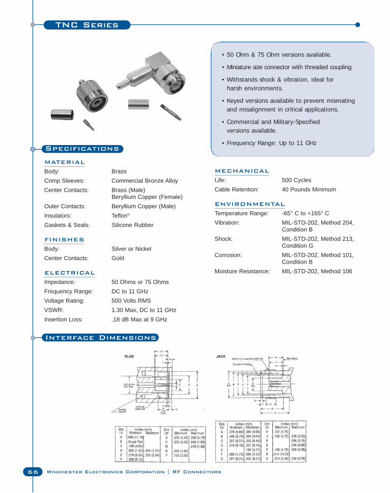
TNC Series
66 Winchester Electronics Corporation | RF Connectors
Specifications
MATERIAL
Body: BrassCrimp Sleeves: Commercial Bronze AlloyCenter Contacts: Brass (Male)
Beryllium Copper (Female)Outer Contacts: Beryllium Copper (Male)Insulators: Teflon®
Gaskets & Seals: Silicone Rubber
FINISHES
Body: Silver or NickelCenter Contacts: Gold
ELECTRICAL
Impedance: 50 Ohms or 75 OhmsFrequency Range: DC to 11 GHzVoltage Rating: 500 Volts RMSVSWR: 1.30 Max, DC to 11 GHzInsertion Loss: .18 dB Max at 9 GHz
• 50 Ohm & 75 Ohm versions available.
• Miniature size connector with threaded coupling.
• Withstands shock & vibration, ideal for harsh environments.
• Keyed versions available to prevent mismatingand misalignment in critical applications.
• Commercial and Military-Specified versions available.
• Frequency Range: Up to 11 GHz
MECHANICAL
Life: 500 CyclesCable Retention: 40 Pounds Minimum
ENVIRONMENTAL
Temperature Range: -65° C to +165° CVibration: MIL-STD-202, Method 204,
Condition BShock: MIL-STD-202, Method 213,
Condition GCorrosion: MIL-STD-202, Method 101,
Condition BMoisture Resistance: MIL-STD-202, Method 106
Interface Dimensions
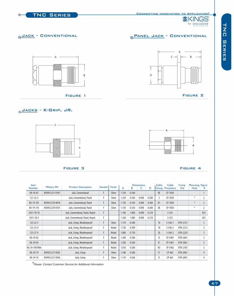
Connecting Innovation to Application®TNC Series
67
TN
C S
erie
s
Figure 1 Figure 2
Figure 3 Figure 4
Item Dimensions Cable Cable Crimp Mounting FigureNumber Military PN Product Description Gender Finish A B C D Group Procedure Die Hole #
KA-39-87 M39012/27-0101 Jack, Conventional F Silver 1.150 0.560 DE CP-1050 1
121-25-5 Jack, Conventional, Panel F Silver 1.250 0.560 0.090 0.500 3 CP-1050 * 2
KA-19-181 M39012/29-0018 Jack, Conventional, Panel F Silver 1.150 0.550 0.090 0.500 B1 CP-1050 * 2
KA-19-176 M39012/29-0101 Jack, Conventional, Panel F Silver 1.150 0.550 0.090 0.500 DE CP-1050 * 2
2431-78-10 Jack, Conventional, Panel, Keyed F 1.160 1.000 0.090 0.210 3-355 N/S
2431-78-5 Jack, Conventional, Panel, Keyed F 1.160 1.000 0.090 0.210 3-355 N/S
123-22-5 Jack, Crimp, Weatherproof F Silver 1.170 0.580 16 3-546-1 KTH-2121 3
123-23-9 Jack, Crimp, Weatherproof F Nickel 1.720 0.590 18 3-546-2 KTH-2212 3
123-27-9 Jack, Crimp, Weatherproof F Nickel 1.800 0.730 20 3-546-2 KTH-2229 3
KA-39-82 Jack, Crimp, Weatherproof F Nickel 1.200 0.580 D CP-5401 KTH-2061 3
KA-39-85 Jack, Crimp, Weatherproof F Nickel 1.200 0.560 E1 CP-5401 KTH-2061 3
KA-39-100 M06 Jack, Crimp, Weatherproof F Nickel 1.810 0.500 N3 CP-5402 KTH-2105 3
KA-39-79 M39012/27-0503 Jack, Crimp F Silver 1.180 0.580 E1 CP-465 KTH-2001 4
KA-39-76 M39012/27-0504 Jack, Crimp F Silver 1.170 0.560 D CP-465 KTH-2001 4
Jack - Conventional Panel Jack - Conventional
Jacks - K-Grip, JR.
*Please Contact Customer Service for Additional Information
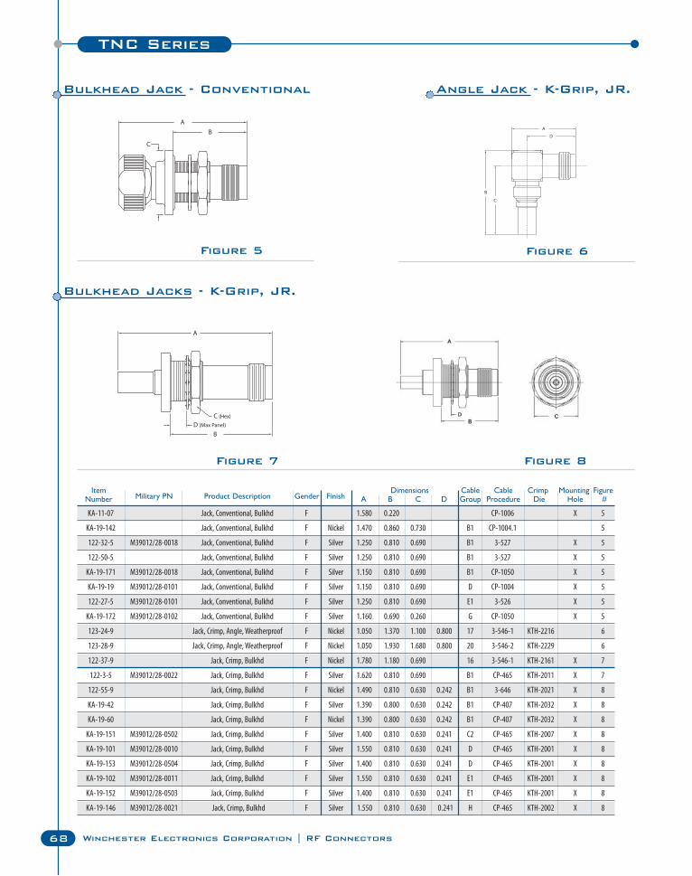
TNC Series
68 Winchester Electronics Corporation | RF Connectors
Figure 5 Figure 6
Figure 7 Figure 8
Item Dimensions Cable Cable Crimp Mounting FigureNumber Military PN Product Description Gender Finish A B C D Group Procedure Die Hole #
KA-11-07 Jack, Conventional, Bulkhd F 1.580 0.220 CP-1006 X 5
KA-19-142 Jack, Conventional, Bulkhd F Nickel 1.470 0.860 0.730 B1 CP-1004.1 5
122-32-5 M39012/28-0018 Jack, Conventional, Bulkhd F Silver 1.250 0.810 0.690 B1 3-527 X 5
122-50-5 Jack, Conventional, Bulkhd F Silver 1.250 0.810 0.690 B1 3-527 X 5
KA-19-171 M39012/28-0018 Jack, Conventional, Bulkhd F Silver 1.150 0.810 0.690 B1 CP-1050 X 5
KA-19-19 M39012/28-0101 Jack, Conventional, Bulkhd F Silver 1.150 0.810 0.690 D CP-1004 X 5
122-27-5 M39012/28-0101 Jack, Conventional, Bulkhd F Silver 1.250 0.810 0.690 E1 3-526 X 5
KA-19-172 M39012/28-0102 Jack, Conventional, Bulkhd F Silver 1.160 0.690 0.260 G CP-1050 X 5
123-24-9 Jack, Crimp, Angle, Weatherproof F Nickel 1.050 1.370 1.100 0.800 17 3-546-1 KTH-2216 6
123-28-9 Jack, Crimp, Angle, Weatherproof F Nickel 1.050 1.930 1.680 0.800 20 3-546-2 KTH-2229 6
122-37-9 Jack, Crimp, Bulkhd F Nickel 1.780 1.180 0.690 16 3-546-1 KTH-2161 X 7
122-3-5 M39012/28-0022 Jack, Crimp, Bulkhd F Silver 1.620 0.810 0.690 B1 CP-465 KTH-2011 X 7
122-55-9 Jack, Crimp, Bulkhd F Nickel 1.490 0.810 0.630 0.242 B1 3-646 KTH-2021 X 8
KA-19-42 Jack, Crimp, Bulkhd F Silver 1.390 0.800 0.630 0.242 B1 CP-407 KTH-2032 X 8
KA-19-60 Jack, Crimp, Bulkhd F Nickel 1.390 0.800 0.630 0.242 B1 CP-407 KTH-2032 X 8
KA-19-151 M39012/28-0502 Jack, Crimp, Bulkhd F Silver 1.400 0.810 0.630 0.241 C2 CP-465 KTH-2007 X 8
KA-19-101 M39012/28-0010 Jack, Crimp, Bulkhd F Silver 1.550 0.810 0.630 0.241 D CP-465 KTH-2001 X 8
KA-19-153 M39012/28-0504 Jack, Crimp, Bulkhd F Silver 1.400 0.810 0.630 0.241 D CP-465 KTH-2001 X 8
KA-19-102 M39012/28-0011 Jack, Crimp, Bulkhd F Silver 1.550 0.810 0.630 0.241 E1 CP-465 KTH-2001 X 8
KA-19-152 M39012/28-0503 Jack, Crimp, Bulkhd F Silver 1.400 0.810 0.630 0.241 E1 CP-465 KTH-2001 X 8
KA-19-146 M39012/28-0021 Jack, Crimp, Bulkhd F Silver 1.550 0.810 0.630 0.241 H CP-465 KTH-2002 X 8
Bulkhead Jack - Conventional Angle Jack - K-Grip, JR.
Bulkhead Jacks - K-Grip, JR.
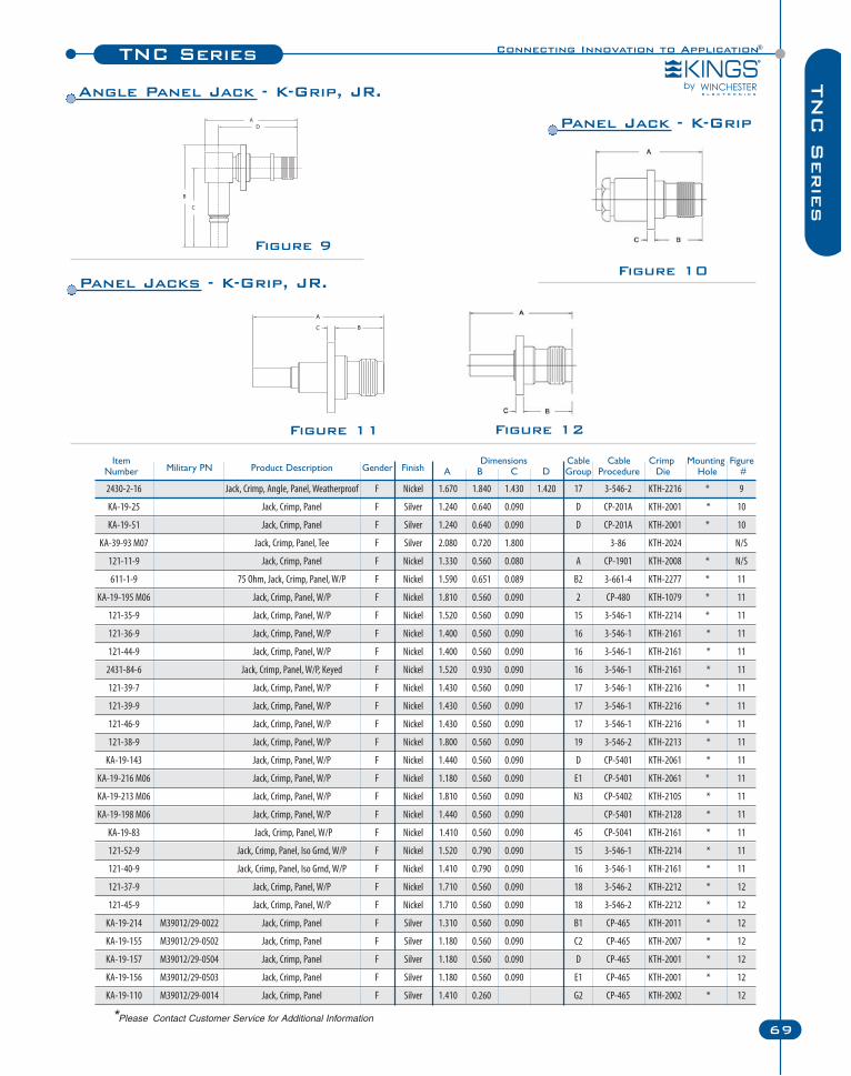
Connecting Innovation to Application®TNC Series
69
TN
C S
erie
s
Figure 11 Figure 12
Figure 10
Figure 9
Item Dimensions Cable Cable Crimp Mounting FigureNumber Military PN Product Description Gender Finish A B C D Group Procedure Die Hole #
2430-2-16 Jack, Crimp, Angle, Panel, Weatherproof F Nickel 1.670 1.840 1.430 1.420 17 3-546-2 KTH-2216 * 9
KA-19-25 Jack, Crimp, Panel F Silver 1.240 0.640 0.090 D CP-201A KTH-2001 * 10
KA-19-51 Jack, Crimp, Panel F Silver 1.240 0.640 0.090 D CP-201A KTH-2001 * 10
KA-39-93 M07 Jack, Crimp, Panel, Tee F Silver 2.080 0.720 1.800 3-86 KTH-2024 N/S
121-11-9 Jack, Crimp, Panel F Nickel 1.330 0.560 0.080 A CP-1901 KTH-2008 * N/S
611-1-9 75 Ohm, Jack, Crimp, Panel, W/P F Nickel 1.590 0.651 0.089 B2 3-661-4 KTH-2277 * 11
KA-19-195 M06 Jack, Crimp, Panel, W/P F Nickel 1.810 0.560 0.090 2 CP-480 KTH-1079 * 11
121-35-9 Jack, Crimp, Panel, W/P F Nickel 1.520 0.560 0.090 15 3-546-1 KTH-2214 * 11
121-36-9 Jack, Crimp, Panel, W/P F Nickel 1.400 0.560 0.090 16 3-546-1 KTH-2161 * 11
121-44-9 Jack, Crimp, Panel, W/P F Nickel 1.400 0.560 0.090 16 3-546-1 KTH-2161 * 11
2431-84-6 Jack, Crimp, Panel, W/P, Keyed F Nickel 1.520 0.930 0.090 16 3-546-1 KTH-2161 * 11
121-39-7 Jack, Crimp, Panel, W/P F Nickel 1.430 0.560 0.090 17 3-546-1 KTH-2216 * 11
121-39-9 Jack, Crimp, Panel, W/P F Nickel 1.430 0.560 0.090 17 3-546-1 KTH-2216 * 11
121-46-9 Jack, Crimp, Panel, W/P F Nickel 1.430 0.560 0.090 17 3-546-1 KTH-2216 * 11
121-38-9 Jack, Crimp, Panel, W/P F Nickel 1.800 0.560 0.090 19 3-546-2 KTH-2213 * 11
KA-19-143 Jack, Crimp, Panel, W/P F Nickel 1.440 0.560 0.090 D CP-5401 KTH-2061 * 11
KA-19-216 M06 Jack, Crimp, Panel, W/P F Nickel 1.180 0.560 0.090 E1 CP-5401 KTH-2061 * 11
KA-19-213 M06 Jack, Crimp, Panel, W/P F Nickel 1.810 0.560 0.090 N3 CP-5402 KTH-2105 * 11
KA-19-198 M06 Jack, Crimp, Panel, W/P F Nickel 1.440 0.560 0.090 CP-5401 KTH-2128 * 11
KA-19-83 Jack, Crimp, Panel, W/P F Nickel 1.410 0.560 0.090 45 CP-5041 KTH-2161 * 11
121-52-9 Jack, Crimp, Panel, Iso Grnd, W/P F Nickel 1.520 0.790 0.090 15 3-546-1 KTH-2214 * 11
121-40-9 Jack, Crimp, Panel, Iso Grnd, W/P F Nickel 1.410 0.790 0.090 16 3-546-1 KTH-2161 * 11
121-37-9 Jack, Crimp, Panel, W/P F Nickel 1.710 0.560 0.090 18 3-546-2 KTH-2212 * 12
121-45-9 Jack, Crimp, Panel, W/P F Nickel 1.710 0.560 0.090 18 3-546-2 KTH-2212 * 12
KA-19-214 M39012/29-0022 Jack, Crimp, Panel F Silver 1.310 0.560 0.090 B1 CP-465 KTH-2011 * 12
KA-19-155 M39012/29-0502 Jack, Crimp, Panel F Silver 1.180 0.560 0.090 C2 CP-465 KTH-2007 * 12
KA-19-157 M39012/29-0504 Jack, Crimp, Panel F Silver 1.180 0.560 0.090 D CP-465 KTH-2001 * 12
KA-19-156 M39012/29-0503 Jack, Crimp, Panel F Silver 1.180 0.560 0.090 E1 CP-465 KTH-2001 * 12
KA-19-110 M39012/29-0014 Jack, Crimp, Panel F Silver 1.410 0.260 G2 CP-465 KTH-2002 * 12
Panel Jacks - K-Grip, JR.
Panel Jack - K-Grip
Angle Panel Jack - K-Grip, JR.
*Please Contact Customer Service for Additional Information
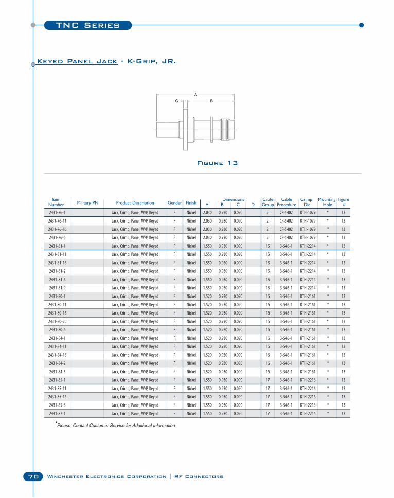
TNC Series
70 Winchester Electronics Corporation | RF Connectors
Figure 13
Item Dimensions Cable Cable Crimp Mounting FigureNumber Military PN Product Description Gender Finish A B C D Group Procedure Die Hole #
2431-76-1 Jack, Crimp, Panel, W/P, Keyed F Nickel 2.030 0.930 0.090 2 CP-5402 KTH-1079 * 13
2431-76-11 Jack, Crimp, Panel, W/P, Keyed F Nickel 2.030 0.930 0.090 2 CP-5402 KTH-1079 * 13
2431-76-16 Jack, Crimp, Panel, W/P, Keyed F Nickel 2.030 0.930 0.090 2 CP-5402 KTH-1079 * 13
2431-76-6 Jack, Crimp, Panel, W/P, Keyed F Nickel 2.030 0.930 0.090 2 CP-5402 KTH-1079 * 13
2431-81-1 Jack, Crimp, Panel, W/P, Keyed F Nickel 1.550 0.930 0.090 15 3-546-1 KTH-2214 * 13
2431-81-11 Jack, Crimp, Panel, W/P, Keyed F Nickel 1.550 0.930 0.090 15 3-546-1 KTH-2214 * 13
2431-81-16 Jack, Crimp, Panel, W/P, Keyed F Nickel 1.550 0.930 0.090 15 3-546-1 KTH-2214 * 13
2431-81-2 Jack, Crimp, Panel, W/P, Keyed F Nickel 1.550 0.930 0.090 15 3-546-1 KTH-2214 * 13
2431-81-6 Jack, Crimp, Panel, W/P, Keyed F Nickel 1.550 0.930 0.090 15 3-546-1 KTH-2214 * 13
2431-81-9 Jack, Crimp, Panel, W/P, Keyed F Nickel 1.550 0.930 0.090 15 3-546-1 KTH-2214 * 13
2431-80-1 Jack, Crimp, Panel, W/P, Keyed F Nickel 1.520 0.930 0.090 16 3-546-1 KTH-2161 * 13
2431-80-11 Jack, Crimp, Panel, W/P, Keyed F Nickel 1.520 0.930 0.090 16 3-546-1 KTH-2161 * 13
2431-80-16 Jack, Crimp, Panel, W/P, Keyed F Nickel 1.520 0.930 0.090 16 3-546-1 KTH-2161 * 13
2431-80-20 Jack, Crimp, Panel, W/P, Keyed F Nickel 1.520 0.930 0.090 16 3-546-1 KTH-2161 * 13
2431-80-6 Jack, Crimp, Panel, W/P, Keyed F Nickel 1.520 0.930 0.090 16 3-546-1 KTH-2161 * 13
2431-84-1 Jack, Crimp, Panel, W/P, Keyed F Nickel 1.520 0.930 0.090 16 3-546-1 KTH-2161 * 13
2431-84-11 Jack, Crimp, Panel, W/P, Keyed F Nickel 1.520 0.930 0.090 16 3-546-1 KTH-2161 * 13
2431-84-16 Jack, Crimp, Panel, W/P, Keyed F Nickel 1.520 0.930 0.090 16 3-546-1 KTH-2161 * 13
2431-84-2 Jack, Crimp, Panel, W/P, Keyed F Nickel 1.520 0.930 0.090 16 3-546-1 KTH-2161 * 13
2431-84-5 Jack, Crimp, Panel, W/P, Keyed F Nickel 1.520 0.930 0.090 16 3-546-1 KTH-2161 * 13
2431-85-1 Jack, Crimp, Panel, W/P, Keyed F Nickel 1.550 0.930 0.090 17 3-546-1 KTH-2216 * 13
2431-85-11 Jack, Crimp, Panel, W/P, Keyed F Nickel 1.550 0.930 0.090 17 3-546-1 KTH-2216 * 13
2431-85-16 Jack, Crimp, Panel, W/P, Keyed F Nickel 1.550 0.930 0.090 17 3-546-1 KTH-2216 * 13
2431-85-6 Jack, Crimp, Panel, W/P, Keyed F Nickel 1.550 0.930 0.090 17 3-546-1 KTH-2216 * 13
2431-87-1 Jack, Crimp, Panel, W/P, Keyed F Nickel 1.550 0.930 0.090 17 3-546-1 KTH-2216 * 13
Keyed Panel Jack - K-Grip, JR.
*Please Contact Customer Service for Additional Information
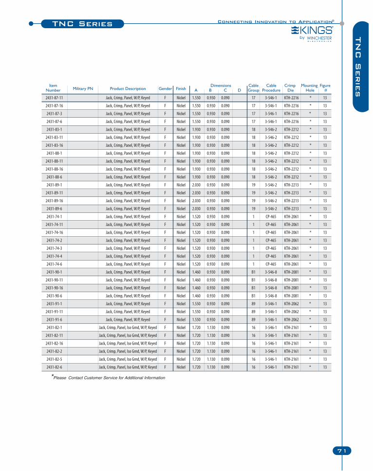
Connecting Innovation to Application®TNC Series
71
TN
C S
erie
sItem Dimensions Cable Cable Crimp Mounting FigureNumber Military PN Product Description Gender Finish A B C D Group Procedure Die Hole #
2431-87-11 Jack, Crimp, Panel, W/P, Keyed F Nickel 1.550 0.930 0.090 17 3-546-1 KTH-2216 * 13
2431-87-16 Jack, Crimp, Panel, W/P, Keyed F Nickel 1.550 0.930 0.090 17 3-546-1 KTH-2216 * 13
2431-87-3 Jack, Crimp, Panel, W/P, Keyed F Nickel 1.550 0.930 0.090 17 3-546-1 KTH-2216 * 13
2431-87-6 Jack, Crimp, Panel, W/P, Keyed F Nickel 1.550 0.930 0.090 17 3-546-1 KTH-2216 * 13
2431-83-1 Jack, Crimp, Panel, W/P, Keyed F Nickel 1.930 0.930 0.090 18 3-546-2 KTH-2212 * 13
2431-83-11 Jack, Crimp, Panel, W/P, Keyed F Nickel 1.930 0.930 0.090 18 3-546-2 KTH-2212 * 13
2431-83-16 Jack, Crimp, Panel, W/P, Keyed F Nickel 1.930 0.930 0.090 18 3-546-2 KTH-2212 * 13
2431-88-1 Jack, Crimp, Panel, W/P, Keyed F Nickel 1.930 0.930 0.090 18 3-546-2 KTH-2212 * 13
2431-88-11 Jack, Crimp, Panel, W/P, Keyed F Nickel 1.930 0.930 0.090 18 3-546-2 KTH-2212 * 13
2431-88-16 Jack, Crimp, Panel, W/P, Keyed F Nickel 1.930 0.930 0.090 18 3-546-2 KTH-2212 * 13
2431-88-6 Jack, Crimp, Panel, W/P, Keyed F Nickel 1.930 0.930 0.090 18 3-546-2 KTH-2212 * 13
2431-89-1 Jack, Crimp, Panel, W/P, Keyed F Nickel 2.030 0.930 0.090 19 3-546-2 KTH-2213 * 13
2431-89-11 Jack, Crimp, Panel, W/P, Keyed F Nickel 2.030 0.930 0.090 19 3-546-2 KTH-2213 * 13
2431-89-16 Jack, Crimp, Panel, W/P, Keyed F Nickel 2.030 0.930 0.090 19 3-546-2 KTH-2213 * 13
2431-89-6 Jack, Crimp, Panel, W/P, Keyed F Nickel 2.030 0.930 0.090 19 3-546-2 KTH-2213 * 13
2431-74-1 Jack, Crimp, Panel, W/P, Keyed F Nickel 1.520 0.930 0.090 1 CP-465 KTH-2061 * 13
2431-74-11 Jack, Crimp, Panel, W/P, Keyed F Nickel 1.520 0.930 0.090 1 CP-465 KTH-2061 * 13
2431-74-16 Jack, Crimp, Panel, W/P, Keyed F Nickel 1.520 0.930 0.090 1 CP-465 KTH-2061 * 13
2431-74-2 Jack, Crimp, Panel, W/P, Keyed F Nickel 1.520 0.930 0.090 1 CP-465 KTH-2061 * 13
2431-74-3 Jack, Crimp, Panel, W/P, Keyed F Nickel 1.520 0.930 0.090 1 CP-465 KTH-2061 * 13
2431-74-4 Jack, Crimp, Panel, W/P, Keyed F Nickel 1.520 0.930 0.090 1 CP-465 KTH-2061 * 13
2431-74-6 Jack, Crimp, Panel, W/P, Keyed F Nickel 1.520 0.930 0.090 1 CP-465 KTH-2061 * 13
2431-90-1 Jack, Crimp, Panel, W/P, Keyed F Nickel 1.460 0.930 0.090 B1 3-546-8 KTH-2081 * 13
2431-90-11 Jack, Crimp, Panel, W/P, Keyed F Nickel 1.460 0.930 0.090 B1 3-546-8 KTH-2081 * 13
2431-90-16 Jack, Crimp, Panel, W/P, Keyed F Nickel 1.460 0.930 0.090 B1 3-546-8 KTH-2081 * 13
2431-90-6 Jack, Crimp, Panel, W/P, Keyed F Nickel 1.460 0.930 0.090 B1 3-546-8 KTH-2081 * 13
2431-91-1 Jack, Crimp, Panel, W/P, Keyed F Nickel 1.550 0.930 0.090 89 3-546-1 KTH-2062 * 13
2431-91-11 Jack, Crimp, Panel, W/P, Keyed F Nickel 1.550 0.930 0.090 89 3-546-1 KTH-2062 * 13
2431-91-6 Jack, Crimp, Panel, W/P, Keyed F Nickel 1.550 0.930 0.090 89 3-546-1 KTH-2062 * 13
2431-82-1 Jack, Crimp, Panel, Iso Grnd, W/P, Keyed F Nickel 1.720 1.130 0.090 16 3-546-1 KTH-2161 * 13
2431-82-11 Jack, Crimp, Panel, Iso Grnd, W/P, Keyed F Nickel 1.720 1.130 0.090 16 3-546-1 KTH-2161 * 13
2431-82-16 Jack, Crimp, Panel, Iso Grnd, W/P, Keyed F Nickel 1.720 1.130 0.090 16 3-546-1 KTH-2161 * 13
2431-82-2 Jack, Crimp, Panel, Iso Grnd, W/P, Keyed F Nickel 1.720 1.130 0.090 16 3-546-1 KTH-2161 * 13
2431-82-5 Jack, Crimp, Panel, Iso Grnd, W/P, Keyed F Nickel 1.720 1.130 0.090 16 3-546-1 KTH-2161 * 13
2431-82-6 Jack, Crimp, Panel, Iso Grnd, W/P, Keyed F Nickel 1.720 1.130 0.090 16 3-546-1 KTH-2161 * 13
*Please Contact Customer Service for Additional Information
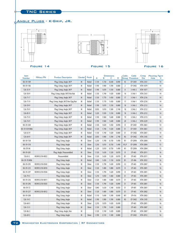
TNC Series
72 Winchester Electronics Corporation | RF Connectors
Figure 14 Figure 16Figure 15
Item Dimensions Cable Cable Crimp Mounting FigureNumber Military PN Product Description Gender Finish A B C D Group Procedure Die Hole #
KA-59-189 Plug, Crimp, Angle, W/P M Nickel 1.130 1.730 0.640 0.890 45 CP-5401 KTH-2161 14
KA-59-186 Plug, Crimp, Angle, W/P M Nickel 1.190 1.900 1.590 0.880 2 CP-5402 KTH-1079 14
126-35-9 Plug, Crimp, Angle, W/P M Nickel 1.190 1.870 1.550 0.880 8 3-440-2 KTH-1077 14
126-58-9 Plug, Crimp, Angle, W/P, Hex Nut M Nickel 1.130 1.740 1.420 0.880 16 3-546-1 KTH-2161 14
126-71-7 Plug, Crimp, Angle, W/P M Nickel 1.130 1.770 1.450 0.880 17 3-546-1 KTH-2216 14
126-71-9 Plug, Crimp, Angle, W/P, Hex Clpg Nut M Nickel 1.130 1.770 1.450 0.880 17 3-546-1 KTH-2216 14
126-59-9 Plug, Crimp, Angle, W/P M Nickel 1.190 1.870 1.550 0.880 18 3-546-2 KTH-2212 14
126-70-9 Plug, Crimp, Angle, W/P M Nickel 3.050 1.810 1.500 2.740 18 3-546-2 KTH-2212 14
126-85-9 Plug, Crimp, Angle, W/P M Nickel 1.220 1.920 1.550 0.880 18 3-546-2 KTH-2212 14
126-73-9 Plug, Crimp, Angle, W/P M Nickel 1.190 1.960 1.640 0.880 19 3-546-2 KTH-2213 14
126-74-9 Plug, Crimp, Angle, W/P M Nickel 1.190 1.960 1.640 0.880 20 3-546-2 KTH-2229 14
KA-59-304 Plug, Crimp, Angle, W/P M Nickel 1.130 1.820 1.450 0.890 D CP-5401 KTH-2061 14
KA-59-439 M06 Plug, Crimp, Angle, W/P M Nickel 1.120 1.740 1.420 0.880 E1 CP-5401 KTH-2061 14
126-63-9 Plug, Crimp, Angle, W/P M Nickel 1.130 1.740 1.420 0.880 E1 CP-5402 KTH-2061 14
126-64-9 Plug, Crimp, Angle, W/P M Nickel 3.050 1.900 1.590 2.740 N3 CP-5402 KTH-2105 14
KA-59-138 Plug, Crimp, Angle M Silver 1.250 1.790 0.750 1.490 N1 CP-209A KTH-2004 15
KA-59-318 Plug, Crimp, Angle M Silver 1.250 1.810 0.750 1.490 N1,P CP-209A KTH-2004 15
KA-59-96 Plug, Crimp, Angle M Nickel 1.220 1.810 0.750 1.490 N1 CP-209A KTH-2004 15
KA-59-281 Plug, Angle, Preassembled M Silver 1.120 1.630 1.320 0.870 B CP-465 KTH-2011 16
126-8-5 M39012/30-0022 Preassembled M Silver 1.120 1.630 1.320 0.870 B1 CP-465 KTH-2011 16
KA-59-70 M06 Plug, Crimp, Angle M Nickel 1.040 1.450 1.150 0.850 B1 CP-406 KTH-2032 16
KA-59-295 M39012/30-0502 Plug, Crimp, Angle M Silver 1.130 1.790 1.420 0.890 C2 CP-465 KTH-2007 16
KA-59-235 M39012/30-0010 Plug, Crimp, Angle M Silver 1.120 1.400 1.080 0.870 D CP-465 KTH-2001 16
KA-59-297 M39012/30-0504 Plug, Crimp, Angle M Silver 1.130 1.790 1.420 0.890 D CP-465 KTH-2001 16
126-79-5 Plug, Crimp, Angle M Silver 1.210 1.850 1.460 0.880 E1 CP-465 KTH-2001 16
KA-59-236 M39012/30-0011 Plug, Crimp, Angle M Silver 1.120 1.400 1.080 0.870 E1 CP-465 KTH-2001 16
KA-59-296 M39012/30-0503 Plug, Crimp, Angle M Silver 1.130 1.790 1.420 0.890 E1 CP-465 KTH-2001 16
KA-59-72 Plug, Crimp, Angle M Silver 1.040 1.630 1.340 0.850 E1 CP-401 KTH-2001 16
KA-59-237 M39012/30-0012 Plug, Crimp, Angle M Silver 1.120 1.400 1.080 0.870 G1 CP-465 KTH-2002 16
KA-59-208 Plug, Crimp, Angle M Nickel 1.110 1.690 1.390 0.840 M1 CP-416 KTH-2003 16
126-14-5 Plug, Crimp, Angle M Nickel 1.190 1.900 1.590 0.880 N3 CP-5402 KTH-2105 16
126-68-5 Plug, Crimp, Angle M Silver 1.210 1.870 1.420 0.690 CP-465 KTH-2001 16
126-12-5 Plug, Crimp, Angle M Silver 1.130 1.790 1.420 0.880 CP-465 KTH-2007 16
126-86-3 Plug, Crimp, Angle, Hex M 1.120 1.740 1.420 0.880 CP-465 KTH-2007 16
126-69-5 Plug, Crimp, Angle M Silver 1.190 2.510 1.500 0.880 CP-5402 KTH-2012 16
Angle Plugs - K-Grip, JR.
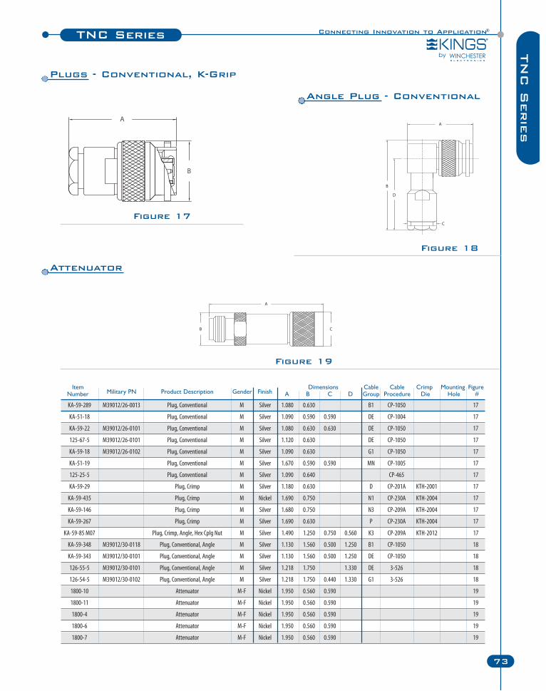
Connecting Innovation to Application®TNC Series
73
TN
C S
erie
s
Item Dimensions Cable Cable Crimp Mounting FigureNumber Military PN Product Description Gender Finish A B C D Group Procedure Die Hole #
KA-59-289 M39012/26-0013 Plug, Conventional M Silver 1.080 0.630 B1 CP-1050 17
KA-51-18 Plug, Conventional M Silver 1.090 0.590 0.590 DE CP-1004 17
KA-59-22 M39012/26-0101 Plug, Conventional M Silver 1.080 0.630 0.630 DE CP-1050 17
125-67-5 M39012/26-0101 Plug, Conventional M Silver 1.120 0.630 DE CP-1050 17
KA-59-18 M39012/26-0102 Plug, Conventional M Silver 1.090 0.630 G1 CP-1050 17
KA-51-19 Plug, Conventional M Silver 1.670 0.590 0.590 MN CP-1005 17
125-25-5 Plug, Conventional M Silver 1.090 0.640 CP-465 17
KA-59-29 Plug, Crimp M Silver 1.180 0.630 D CP-201A KTH-2001 17
KA-59-435 Plug, Crimp M Nickel 1.690 0.750 N1 CP-230A KTH-2004 17
KA-59-146 Plug, Crimp M Silver 1.680 0.750 N3 CP-209A KTH-2004 17
KA-59-267 Plug, Crimp M Silver 1.690 0.630 P CP-230A KTH-2004 17
KA-59-85 M07 Plug, Crimp, Angle, Hex Cplg Nut M Silver 1.490 1.250 0.750 0.560 K3 CP-209A KTH-2012 17
KA-59-348 M39012/30-0118 Plug, Conventional, Angle M Silver 1.130 1.560 0.500 1.250 B1 CP-1050 18
KA-59-343 M39012/30-0101 Plug, Conventional, Angle M Silver 1.130 1.560 0.500 1.250 DE CP-1050 18
126-55-5 M39012/30-0101 Plug, Conventional, Angle M Silver 1.218 1.750 1.330 DE 3-526 18
126-54-5 M39012/30-0102 Plug, Conventional, Angle M Silver 1.218 1.750 0.440 1.330 G1 3-526 18
1800-10 Attenuator M-F Nickel 1.950 0.560 0.590 19
1800-11 Attenuator M-F Nickel 1.950 0.560 0.590 19
1800-4 Attenuator M-F Nickel 1.950 0.560 0.590 19
1800-6 Attenuator M-F Nickel 1.950 0.560 0.590 19
1800-7 Attenuator M-F Nickel 1.950 0.560 0.590 19
Figure 17
Figure 18
Figure 19
Attenuator
Angle Plug - Conventional
Plugs - Conventional, K-Grip
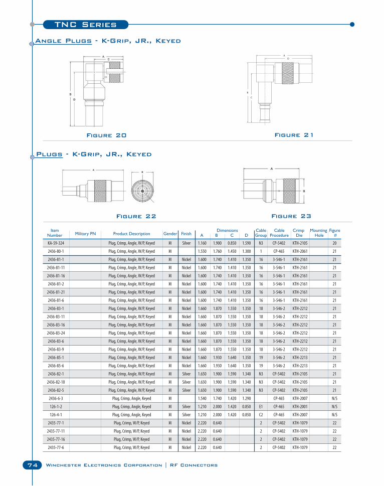
TNC Series
74 Winchester Electronics Corporation | RF Connectors
Figure 20 Figure 21
Item Dimensions Cable Cable Crimp Mounting FigureNumber Military PN Product Description Gender Finish A B C D Group Procedure Die Hole #
KA-59-324 Plug, Crimp, Angle, W/P, Keyed M Silver 1.160 1.900 0.850 1.590 N3 CP-5402 KTH-2105 20
2436-80-1 Plug, Crimp, Angle, W/P, Keyed M 1.550 1.760 1.450 1.300 1 CP-465 KTH-2061 21
2436-81-1 Plug, Crimp, Angle, W/P, Keyed M Nickel 1.600 1.740 1.410 1.350 16 3-546-1 KTH-2161 21
2436-81-11 Plug, Crimp, Angle, W/P, Keyed M Nickel 1.600 1.740 1.410 1.350 16 3-546-1 KTH-2161 21
2436-81-16 Plug, Crimp, Angle, W/P, Keyed M Nickel 1.600 1.740 1.410 1.350 16 3-546-1 KTH-2161 21
2436-81-2 Plug, Crimp, Angle, W/P, Keyed M Nickel 1.600 1.740 1.410 1.350 16 3-546-1 KTH-2161 21
2436-81-21 Plug, Crimp, Angle, W/P, Keyed M Nickel 1.600 1.740 1.410 1.350 16 3-546-1 KTH-2161 21
2436-81-6 Plug, Crimp, Angle, W/P, Keyed M Nickel 1.600 1.740 1.410 1.350 16 3-546-1 KTH-2161 21
2436-83-1 Plug, Crimp, Angle, W/P, Keyed M Nickel 1.660 1.870 1.550 1.350 18 3-546-2 KTH-2212 21
2436-83-11 Plug, Crimp, Angle, W/P, Keyed M Nickel 1.660 1.870 1.550 1.350 18 3-546-2 KTH-2212 21
2436-83-16 Plug, Crimp, Angle, W/P, Keyed M Nickel 1.660 1.870 1.550 1.350 18 3-546-2 KTH-2212 21
2436-83-24 Plug, Crimp, Angle, W/P, Keyed M Nickel 1.660 1.870 1.550 1.350 18 3-546-2 KTH-2212 21
2436-83-6 Plug, Crimp, Angle, W/P, Keyed M Nickel 1.660 1.870 1.550 1.350 18 3-546-2 KTH-2212 21
2436-83-9 Plug, Crimp, Angle, W/P, Keyed M Nickel 1.660 1.870 1.550 1.350 18 3-546-2 KTH-2212 21
2436-85-1 Plug, Crimp, Angle, W/P, Keyed M Nickel 1.660 1.930 1.640 1.350 19 3-546-2 KTH-2213 21
2436-85-6 Plug, Crimp, Angle, W/P, Keyed M Nickel 1.660 1.930 1.640 1.350 19 3-546-2 KTH-2213 21
2436-82-1 Plug, Crimp, Angle, W/P, Keyed M Silver 1.650 1.900 1.590 1.340 N3 CP-5402 KTH-2105 21
2436-82-10 Plug, Crimp, Angle, W/P, Keyed M Silver 1.650 1.900 1.590 1.340 N3 CP-5402 KTH-2105 21
2436-82-5 Plug, Crimp, Angle, W/P, Keyed M Silver 1.650 1.900 1.590 1.340 N3 CP-5402 KTH-2105 21
2436-6-3 Plug, Crimp, Angle, Keyed M 1.540 1.740 1.420 1.290 CP-465 KTH-2007 N/S
126-1-2 Plug, Crimp, Angle, Keyed M Silver 1.210 2.000 1.420 0.850 E1 CP-465 KTH-2001 N/S
126-4-1 Plug, Crimp, Angle, Keyed M Silver 1.210 2.000 1.420 0.850 C2 CP-465 KTH-2007 N/S
2435-77-1 Plug, Crimp, W/P, Keyed M Nickel 2.220 0.640 2 CP-5402 KTH-1079 22
2435-77-11 Plug, Crimp, W/P, Keyed M Nickel 2.220 0.640 2 CP-5402 KTH-1079 22
2435-77-16 Plug, Crimp, W/P, Keyed M Nickel 2.220 0.640 2 CP-5402 KTH-1079 22
2435-77-6 Plug, Crimp, W/P, Keyed M Nickel 2.220 0.640 2 CP-5402 KTH-1079 22
Figure 22 Figure 23
Angle Plugs - K-Grip, JR., Keyed
Plugs - K-Grip, JR., Keyed
Connecting Innovation to Application®TNC Series
75
TN
C S
erie
s
Item Dimensions Cable Cable Crimp Mounting FigureNumber Military PN Product Description Gender Finish A B C D Group Procedure Die Hole #
2435-82-1 Plug, Crimp, W/P, Keyed M Nickel 1.800 0.650 15 3-546-1 KTH-2214 22
2435-82-6 Plug, Crimp, W/P, Keyed M Nickel 1.800 0.650 15 3-546-1 KTH-2214 22
2435-81-1 Plug, Crimp, W/P, Keyed M Nickel 1.580 0.650 16 3-546-1 KTH-2161 22
2435-81-11 Plug, Crimp, W/P, Keyed M Nickel 1.580 0.650 16 3-546-1 KTH-2161 22
2435-81-16 Plug, Crimp, W/P, Keyed M Nickel 1.580 0.650 16 3-546-1 KTH-2161 22
2435-81-2 Plug, Crimp, W/P, Keyed M Nickel 1.580 0.650 16 3-546-1 KTH-2161 22
2435-81-20 Plug, Crimp, W/P, Keyed M Nickel 1.580 0.650 16 3-546-1 KTH-2161 22
2435-81-5 Plug, Crimp, W/P, Keyed M Nickel 1.580 0.650 16 3-546-1 KTH-2161 22
2435-81-6 Plug, Crimp, W/P, Keyed M Nickel 1.580 0.650 16 3-546-1 KTH-2161 22
2435-81-9 Plug, Crimp, W/P, Keyed M Nickel 1.580 0.650 16 3-546-1 KTH-2161 22
2435-84-1 Plug, Crimp, Weatherproof, Keyed M Nickel 1.610 0.650 17 3-546-1 KTH-2216 22
2435-84-11 Plug, Crimp, Weatherproof, Keyed M Nickel 1.610 0.650 17 3-546-1 KTH-2216 22
2435-84-16 Plug, Crimp, Weatherproof, Keyed M Nickel 1.610 0.650 17 3-546-1 KTH-2216 22
2435-84-3 Plug, Crimp, Weatherproof, Keyed M Nickel 1.610 0.650 17 3-546-1 KTH-2216 22
2435-84-5 Plug, Crimp, Weatherproof, Keyed M Nickel 1.610 0.650 17 3-546-1 KTH-2216 22
2435-84-6 Plug, Crimp, Weatherproof, Keyed M Nickel 1.610 0.650 17 3-546-1 KTH-2216 22
2435-83-1 Plug, Crimp, Weatherproof, Keyed M Nickel 2.130 0.650 18 3-546-2 KTH-2212 22
2435-83-11 Plug, Crimp, Weatherproof, Keyed M Nickel 2.130 0.650 18 3-546-2 KTH-2212 22
2435-83-16 Plug, Crimp, Weatherproof, Keyed M Nickel 2.130 0.650 18 3-546-2 KTH-2212 22
2435-83-6 Plug, Crimp, Weatherproof, Keyed M Nickel 2.130 0.650 18 3-546-2 KTH-2212 22
2435-87-1 Plug, Crimp, Weatherproof, Keyed M Nickel 2.215 0.650 19 3-546-2 KTH-2213 22
2435-87-11 Plug, Crimp, Weatherproof, Keyed M Nickel 2.215 0.650 19 3-546-2 KTH-2213 22
2435-87-16 Plug, Crimp, Weatherproof, Keyed M Nickel 2.215 0.650 19 3-546-2 KTH-2213 22
2435-87-6 Plug, Crimp, Weatherproof, Keyed M Nickel 2.215 0.650 19 3-546-2 KTH-2213 22
2435-89-1 Plug, Crimp, Weatherproof, Keyed M Nickel 2.330 0.650 20 3-546-2 KTH-2229 22
2435-89-11 Plug, Crimp, Weatherproof, Keyed M Nickel 2.330 0.650 20 3-546-2 KTH-2229 22
2435-89-16 Plug, Crimp, Weatherproof, Keyed M Nickel 2.330 0.650 20 3-546-2 KTH-2229 22
2435-89-6 Plug, Crimp, Weatherproof, Keyed M Nickel 2.330 0.650 20 3-546-2 KTH-2229 22
2435-74-1 Plug, Crimp, Weatherproof, Keyed M Nickel 1.580 0.650 E1 CP-465 KTH-2061 22
2435-74-11 Plug, Crimp, Weatherproof, Keyed M Nickel 1.580 0.650 E1 CP-465 KTH-2061 22
2435-74-16 Plug, Crimp, Weatherproof, Keyed M Nickel 1.580 0.650 E1 CP-465 KTH-2061 22
2435-74-3 Plug, Crimp, Weatherproof, Keyed M Nickel 1.580 0.650 E1 CP-465 KTH-2061 22
2435-74-6 Plug, Crimp, Weatherproof, Keyed M Nickel 1.580 0.650 E1 CP-465 KTH-2061 22
2435-88-1 Plug, Crimp, W/P, Keyed M Nickel 1.580 0.640 89 3-440-3 KTH-2062 22
2435-88-11 Plug, Crimp, W/P, Keyed M Nickel 1.580 0.640 89 3-440-3 KTH-2062 22
2435-88-16 Plug, Crimp, W/P, Keyed M Nickel 1.580 0.640 89 3-440-3 KTH-2062 22
2435-88-6 Plug, Crimp, W/P, Keyed M Nickel 1.580 0.640 89 3-440-3 KTH-2062 22
125-4-1 Plug, Crimp, Keyed M Silver 1.500 0.610 C2 CP-465 N/S
125-4-2 Plug, Crimp, Keyed M Silver 1.500 0.610 C2 CP-465 KTH-2007 N/S
125-86-1 Plug, Crimp, Keyed M Silver 1.240 0.610 D CP-465 KTH-2001 N/S
125-1-1 Plug, Crimp, Keyed M Silver 1.240 0.610 E1 CP-465 KTH-2001 N/S
125-1-6 Plug, Crimp, Keyed M Silver 1.500 0.610 E1 CP-465 KTH-2001 N/S
125-52-1 Plug, Crimp, Keyed M Silver 2.000 0.610 11 CP-5402 KTH-2012 23
125-52-2 Plug, Crimp, Keyed M Silver 2.000 0.610 11 CP-5402 KTH-2012 23
125-52-3 Plug, Crimp, Keyed M Silver 2.000 0.610 11 CP-5402 KTH-2012 23
125-52-4 Plug, Crimp, Keyed M Silver 2.000 0.610 11 CP-5402 KTH-2012 23
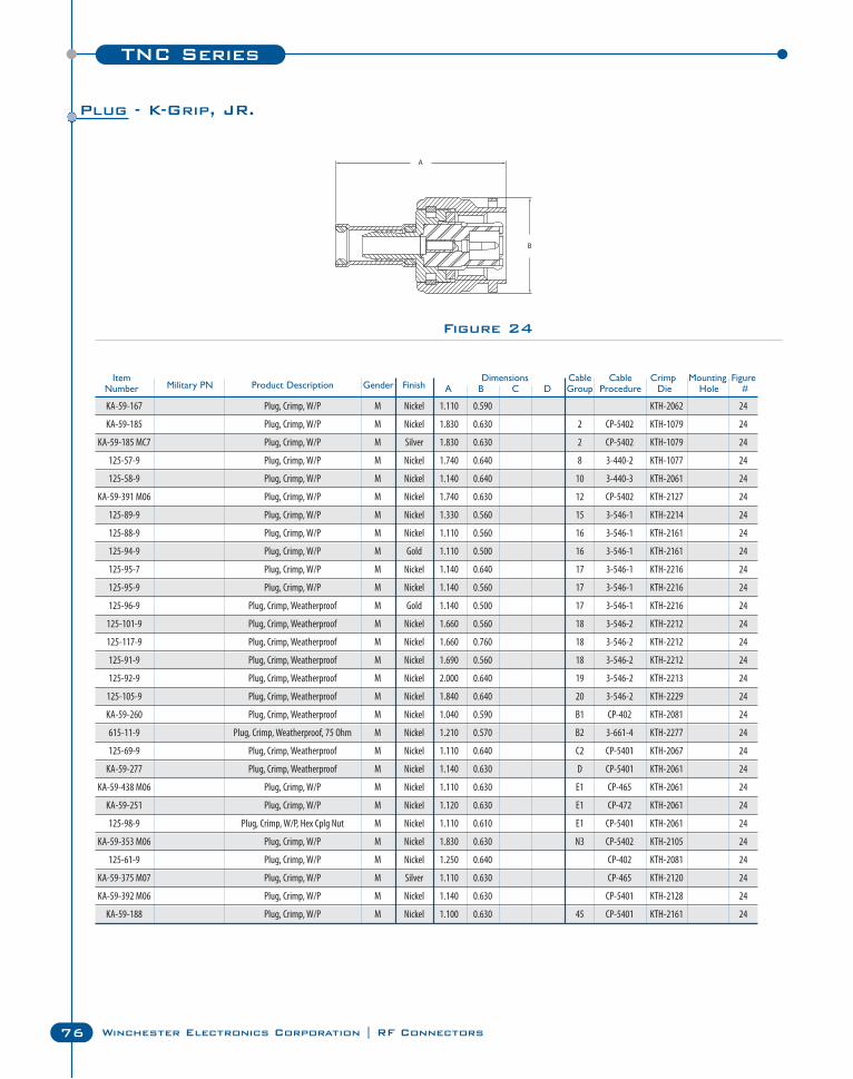
TNC Series
76 Winchester Electronics Corporation | RF Connectors
Figure 24
Item Dimensions Cable Cable Crimp Mounting FigureNumber Military PN Product Description Gender Finish A B C D Group Procedure Die Hole #
KA-59-167 Plug, Crimp, W/P M Nickel 1.110 0.590 KTH-2062 24
KA-59-185 Plug, Crimp, W/P M Nickel 1.830 0.630 2 CP-5402 KTH-1079 24
KA-59-185 MC7 Plug, Crimp, W/P M Silver 1.830 0.630 2 CP-5402 KTH-1079 24
125-57-9 Plug, Crimp, W/P M Nickel 1.740 0.640 8 3-440-2 KTH-1077 24
125-58-9 Plug, Crimp, W/P M Nickel 1.140 0.640 10 3-440-3 KTH-2061 24
KA-59-391 M06 Plug, Crimp, W/P M Nickel 1.740 0.630 12 CP-5402 KTH-2127 24
125-89-9 Plug, Crimp, W/P M Nickel 1.330 0.560 15 3-546-1 KTH-2214 24
125-88-9 Plug, Crimp, W/P M Nickel 1.110 0.560 16 3-546-1 KTH-2161 24
125-94-9 Plug, Crimp, W/P M Gold 1.110 0.500 16 3-546-1 KTH-2161 24
125-95-7 Plug, Crimp, W/P M Nickel 1.140 0.640 17 3-546-1 KTH-2216 24
125-95-9 Plug, Crimp, W/P M Nickel 1.140 0.560 17 3-546-1 KTH-2216 24
125-96-9 Plug, Crimp, Weatherproof M Gold 1.140 0.500 17 3-546-1 KTH-2216 24
125-101-9 Plug, Crimp, Weatherproof M Nickel 1.660 0.560 18 3-546-2 KTH-2212 24
125-117-9 Plug, Crimp, Weatherproof M Nickel 1.660 0.760 18 3-546-2 KTH-2212 24
125-91-9 Plug, Crimp, Weatherproof M Nickel 1.690 0.560 18 3-546-2 KTH-2212 24
125-92-9 Plug, Crimp, Weatherproof M Nickel 2.000 0.640 19 3-546-2 KTH-2213 24
125-105-9 Plug, Crimp, Weatherproof M Nickel 1.840 0.640 20 3-546-2 KTH-2229 24
KA-59-260 Plug, Crimp, Weatherproof M Nickel 1.040 0.590 B1 CP-402 KTH-2081 24
615-11-9 Plug, Crimp, Weatherproof, 75 Ohm M Nickel 1.210 0.570 B2 3-661-4 KTH-2277 24
125-69-9 Plug, Crimp, Weatherproof M Nickel 1.110 0.640 C2 CP-5401 KTH-2067 24
KA-59-277 Plug, Crimp, Weatherproof M Nickel 1.140 0.630 D CP-5401 KTH-2061 24
KA-59-438 M06 Plug, Crimp, W/P M Nickel 1.110 0.630 E1 CP-465 KTH-2061 24
KA-59-251 Plug, Crimp, W/P M Nickel 1.120 0.630 E1 CP-472 KTH-2061 24
125-98-9 Plug, Crimp, W/P, Hex Cplg Nut M Nickel 1.110 0.610 E1 CP-5401 KTH-2061 24
KA-59-353 M06 Plug, Crimp, W/P M Nickel 1.830 0.630 N3 CP-5402 KTH-2105 24
125-61-9 Plug, Crimp, W/P M Nickel 1.250 0.640 CP-402 KTH-2081 24
KA-59-375 M07 Plug, Crimp, W/P M Silver 1.110 0.630 CP-465 KTH-2120 24
KA-59-392 M06 Plug, Crimp, W/P M Nickel 1.140 0.630 CP-5401 KTH-2128 24
KA-59-188 Plug, Crimp, W/P M Nickel 1.100 0.630 45 CP-5401 KTH-2161 24
Plug - K-Grip, JR.
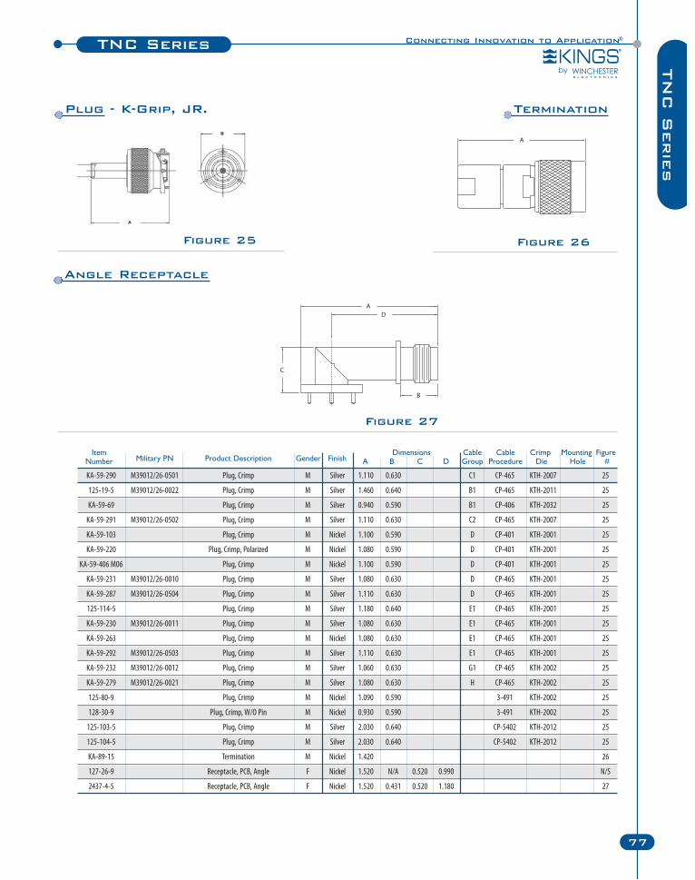
Connecting Innovation to Application®TNC Series
77
TN
C S
erie
s
Item Dimensions Cable Cable Crimp Mounting FigureNumber Military PN Product Description Gender Finish A B C D Group Procedure Die Hole #
KA-59-290 M39012/26-0501 Plug, Crimp M Silver 1.110 0.630 C1 CP-465 KTH-2007 25
125-19-5 M39012/26-0022 Plug, Crimp M Silver 1.460 0.640 B1 CP-465 KTH-2011 25
KA-59-69 Plug, Crimp M Silver 0.940 0.590 B1 CP-406 KTH-2032 25
KA-59-291 M39012/26-0502 Plug, Crimp M Silver 1.110 0.630 C2 CP-465 KTH-2007 25
KA-59-103 Plug, Crimp M Nickel 1.100 0.590 D CP-401 KTH-2001 25
KA-59-220 Plug, Crimp, Polarized M Nickel 1.080 0.590 D CP-401 KTH-2001 25
KA-59-406 M06 Plug, Crimp M Nickel 1.100 0.590 D CP-401 KTH-2001 25
KA-59-231 M39012/26-0010 Plug, Crimp M Silver 1.080 0.630 D CP-465 KTH-2001 25
KA-59-287 M39012/26-0504 Plug, Crimp M Silver 1.110 0.630 D CP-465 KTH-2001 25
125-114-5 Plug, Crimp M Silver 1.180 0.640 E1 CP-465 KTH-2001 25
KA-59-230 M39012/26-0011 Plug, Crimp M Silver 1.080 0.630 E1 CP-465 KTH-2001 25
KA-59-263 Plug, Crimp M Nickel 1.080 0.630 E1 CP-465 KTH-2001 25
KA-59-292 M39012/26-0503 Plug, Crimp M Silver 1.110 0.630 E1 CP-465 KTH-2001 25
KA-59-232 M39012/26-0012 Plug, Crimp M Silver 1.060 0.630 G1 CP-465 KTH-2002 25
KA-59-279 M39012/26-0021 Plug, Crimp M Silver 1.080 0.630 H CP-465 KTH-2002 25
125-80-9 Plug, Crimp M Nickel 1.090 0.590 3-491 KTH-2002 25
128-30-9 Plug, Crimp, W/O Pin M Nickel 0.930 0.590 3-491 KTH-2002 25
125-103-5 Plug, Crimp M Silver 2.030 0.640 CP-5402 KTH-2012 25
125-104-5 Plug, Crimp M Silver 2.030 0.640 CP-5402 KTH-2012 25
KA-89-15 Termination M Nickel 1.420 26
127-26-9 Receptacle, PCB, Angle F Nickel 1.520 N/A 0.520 0.990 N/S
2437-4-5 Receptacle, PCB, Angle F Nickel 1.520 0.431 0.520 1.180 27
Figure 25
Figure 27
Figure 26
Plug - K-Grip, JR. Termination
Angle Receptacle
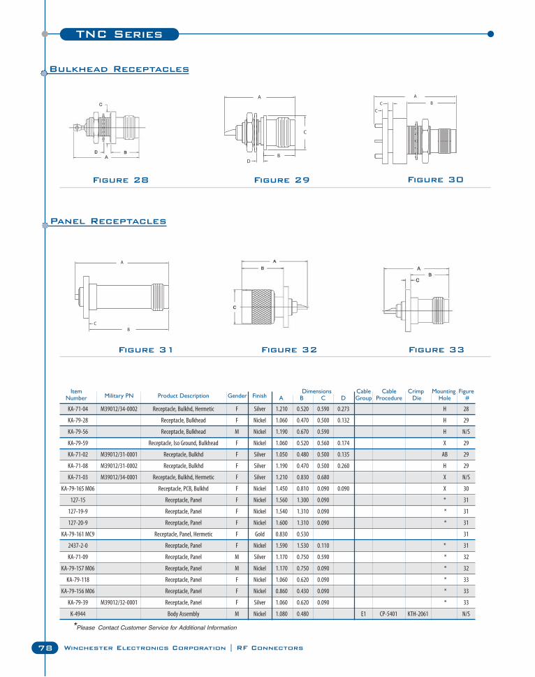
TNC Series
78 Winchester Electronics Corporation | RF Connectors
Figure 28 Figure 29 Figure 30
Figure 31 Figure 32 Figure 33
Item Dimensions Cable Cable Crimp Mounting FigureNumber Military PN Product Description Gender Finish A B C D Group Procedure Die Hole #
KA-71-04 M39012/34-0002 Receptacle, Bulkhd, Hermetic F Silver 1.210 0.520 0.590 0.273 H 28
KA-79-28 Receptacle, Bulkhead F Nickel 1.060 0.470 0.500 0.132 H 29
KA-79-56 Receptacle, Bulkhead M Nickel 1.190 0.670 0.590 H N/S
KA-79-59 Receptacle, Iso Ground, Bulkhead F Nickel 1.060 0.520 0.560 0.174 X 29
KA-71-02 M39012/31-0001 Receptacle, Bulkhd F Silver 1.050 0.480 0.500 0.135 AB 29
KA-71-08 M39012/31-0002 Receptacle, Bulkhd F Silver 1.190 0.470 0.500 0.260 H 29
KA-71-03 M39012/34-0001 Receptacle, Bulkhd, Hermetic F Silver 1.210 0.830 0.680 X N/S
KA-79-165 M06 Receptacle, PCB, Bulkhd F Nickel 1.450 0.810 0.090 0.090 X 30
127-15 Receptacle, Panel F Nickel 1.560 1.300 0.090 * 31
127-19-9 Receptacle, Panel F Nickel 1.540 1.310 0.090 * 31
127-20-9 Receptacle, Panel F Nickel 1.600 1.310 0.090 * 31
KA-79-161 MC9 Receptacle, Panel, Hermetic F Gold 0.830 0.530 31
2437-2-0 Receptacle, Panel F Nickel 1.590 1.530 0.110 * 31
KA-71-09 Receptacle, Panel M Silver 1.170 0.750 0.590 * 32
KA-79-157 M06 Receptacle, Panel M Nickel 1.170 0.750 0.090 * 32
KA-79-118 Receptacle, Panel F Nickel 1.060 0.620 0.090 * 33
KA-79-156 M06 Receptacle, Panel F Nickel 0.860 0.430 0.090 * 33
KA-79-39 M39012/32-0001 Receptacle, Panel F Silver 1.060 0.620 0.090 * 33
K-4944 Body Assembly M Nickel 1.080 0.480 E1 CP-5401 KTH-2061 N/S
Bulkhead Receptacles
Panel Receptacles
*Please Contact Customer Service for Additional Information
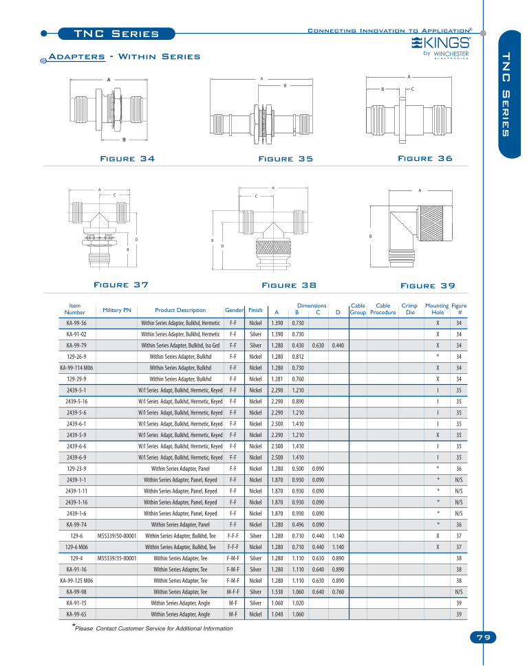
KA-99-56 Within Series Adapter, Bulkhd, Hermetic F-F Nickel 1.390 0.730 X 34
KA-91-02 Within Series Adapter, Bulkhd, Hermetic F-F Silver 1.390 0.730 X 34
KA-99-79 Within Series Adapter, Bulkhd, Iso Grd F-F Silver 1.280 0.430 0.630 0.440 X 34
129-26-9 Within Series Adapter, Bulkhd F-F Nickel 1.280 0.812 * 34
KA-99-114 M06 Within Series Adapter, Bulkhd F-F Nickel 1.280 0.730 X 34
129-29-9 Within Series Adapter, Bulkhd F-F Nickel 1.281 0.760 X 34
2439-5-1 W/I Series Adapt, Bulkhd, Hermetic, Keyed F-F Nickel 2.290 1.210 I 35
2439-5-16 W/I Series Adapt, Bulkhd, Hermetic, Keyed F-F Nickel 2.290 0.890 I 35
2439-5-6 W/I Series Adapt, Bulkhd, Hermetic, Keyed F-F Nickel 2.290 1.210 I 35
2439-6-1 W/I Series Adapt, Bulkhd, Hermetic, Keyed F-F Nickel 2.500 1.410 I 35
2439-5-9 W/I Series Adapt, Bulkhd, Hermetic, Keyed F-F Nickel 2.290 1.210 X 35
2439-6-6 W/I Series Adapt, Bulkhd, Hermetic, Keyed F-F Nickel 2.500 1.410 I 35
2439-6-9 W/I Series Adapt, Bulkhd, Hermetic, Keyed F-F Nickel 2.500 1.410 I 35
129-23-9 Within Series Adapter, Panel F-F Nickel 1.280 0.500 0.090 * 36
2439-1-1 Within Series Adapter, Panel, Keyed F-F Nickel 1.870 0.930 0.090 * N/S
2439-1-11 Within Series Adapter, Panel, Keyed F-F Nickel 1.870 0.930 0.090 * N/S
2439-1-16 Within Series Adapter, Panel, Keyed F-F Nickel 1.870 0.930 0.090 * N/S
2439-1-6 Within Series Adapter, Panel, Keyed F-F Nickel 1.870 0.930 0.090 * N/S
KA-99-74 Within Series Adapter, Panel F-F Nickel 1.280 0.496 0.090 * 36
129-6 M55339/50-00001 Within Series Adapter, Bulkhd, Tee F-F-F Silver 1.280 0.710 0.440 1.140 X 37
129-6 M06 Within Series Adapter, Bulkhd, Tee F-F-F Nickel 1.280 0.710 0.440 1.140 X 37
129-4 M55339/35-00001 Within Series Adapter, Tee F-M-F Silver 1.280 1.110 0.630 0.890 38
KA-91-16 Within Series Adapter, Tee F-M-F Silver 1.280 1.110 0.640 0.890 38
KA-99-125 M06 Within Series Adapter, Tee F-M-F Nickel 1.280 1.110 0.630 0.890 38
KA-99-98 Within Series Adapter, Tee M-F-F Silver 1.530 1.060 0.640 0.760 N/S
KA-91-15 Within Series Adapter, Angle M-F Silver 1.060 1.020 39
KA-99-65 Within Series Adapter, Angle M-F Nickel 1.040 1.060 39
Connecting Innovation to Application®TNC Series
79
TN
C S
erie
s
Figure 34 Figure 35 Figure 36
Figure 38 Figure 39Figure 37
Item Dimensions Cable Cable Crimp Mounting FigureNumber Military PN Product Description Gender Finish A B C D Group Procedure Die Hole #
Adapters - Within Series
*Please Contact Customer Service for Additional Information
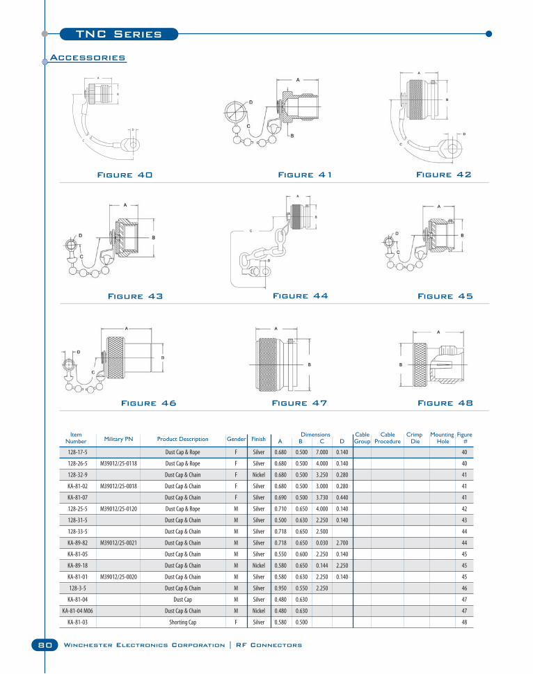
TNC Series
80 Winchester Electronics Corporation | RF Connectors
Figure 40 Figure 41 Figure 42
Figure 43 Figure 44 Figure 45
Figure 46 Figure 47 Figure 48
Item Dimensions Cable Cable Crimp Mounting FigureNumber Military PN Product Description Gender Finish A B C D Group Procedure Die Hole #
128-17-5 Dust Cap & Rope F Silver 0.680 0.500 7.000 0.140 40
128-26-5 M39012/25-0118 Dust Cap & Rope F Silver 0.680 0.500 4.000 0.140 40
128-32-9 Dust Cap & Chain F Nickel 0.680 0.500 3.250 0.280 41
KA-81-02 M39012/25-0018 Dust Cap & Chain F Silver 0.680 0.500 3.000 0.280 41
KA-81-07 Dust Cap & Chain F Silver 0.690 0.500 3.730 0.440 41
128-25-5 M39012/25-0120 Dust Cap & Rope M Silver 0.710 0.650 4.000 0.140 42
128-31-5 Dust Cap & Chain M Silver 0.500 0.630 2.250 0.140 43
128-33-5 Dust Cap & Chain M Silver 0.718 0.650 2.500 44
KA-89-82 M39012/25-0021 Dust Cap & Chain M Silver 0.718 0.650 0.030 2.700 44
KA-81-05 Dust Cap & Chain M Silver 0.550 0.600 2.250 0.140 45
KA-89-18 Dust Cap & Chain M Nickel 0.580 0.650 0.144 2.250 45
KA-81-01 M39012/25-0020 Dust Cap & Chain M Silver 0.580 0.630 2.250 0.140 45
128-3-5 Dust Cap & Chain M Silver 0.950 0.550 2.250 46
KA-81-04 Dust Cap M Silver 0.480 0.630 47
KA-81-04 M06 Dust Cap & Chain M Nickel 0.480 0.630 47
KA-81-03 Shorting Cap F Silver 0.580 0.500 48
Accessories
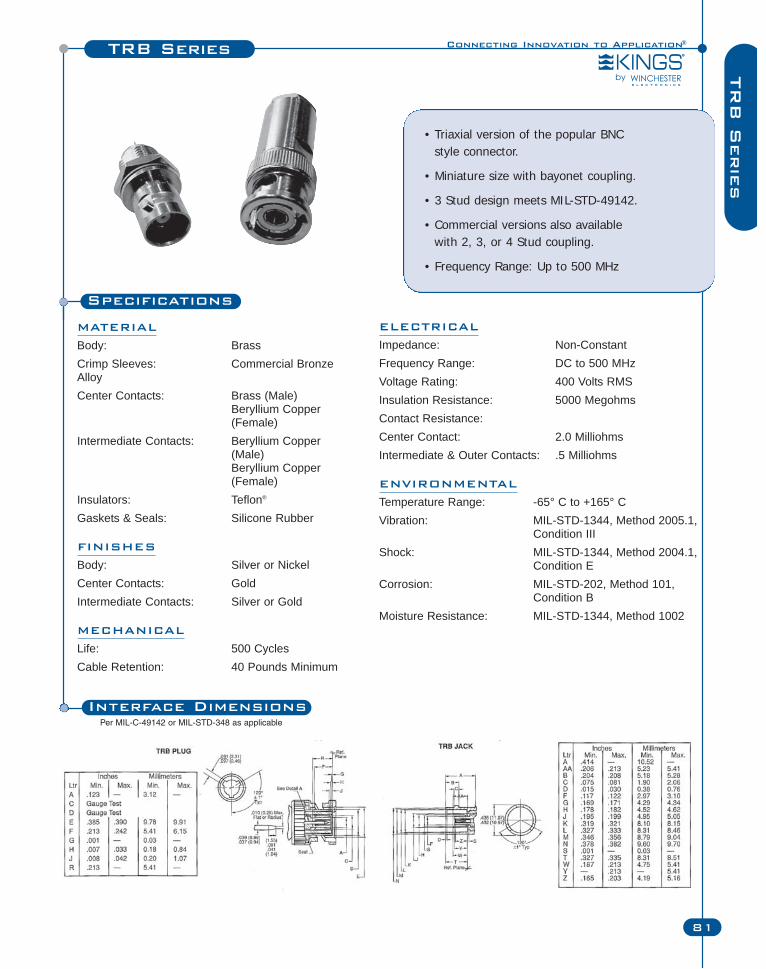
Specifications
MATERIAL
Body: BrassCrimp Sleeves: Commercial BronzeAlloyCenter Contacts: Brass (Male)
Beryllium Copper (Female)
Intermediate Contacts: Beryllium Copper (Male)Beryllium Copper (Female)
Insulators: Teflon®
Gaskets & Seals: Silicone Rubber
FINISHES
Body: Silver or NickelCenter Contacts: GoldIntermediate Contacts: Silver or Gold
MECHANICAL
Life: 500 CyclesCable Retention: 40 Pounds Minimum
• Triaxial version of the popular BNC style connector.
• Miniature size with bayonet coupling.
• 3 Stud design meets MIL-STD-49142.
• Commercial versions also available with 2, 3, or 4 Stud coupling.
• Frequency Range: Up to 500 MHz
Connecting Innovation to Application®TRB Series
81
TR
B S
erie
s
ELECTRICAL
Impedance: Non-ConstantFrequency Range: DC to 500 MHzVoltage Rating: 400 Volts RMSInsulation Resistance: 5000 MegohmsContact Resistance:Center Contact: 2.0 MilliohmsIntermediate & Outer Contacts: .5 Milliohms
ENVIRONMENTAL
Temperature Range: -65° C to +165° CVibration: MIL-STD-1344, Method 2005.1,
Condition IIIShock: MIL-STD-1344, Method 2004.1,
Condition ECorrosion: MIL-STD-202, Method 101,
Condition BMoisture Resistance: MIL-STD-1344, Method 1002
Interface DimensionsPer MIL-C-49142 or MIL-STD-348 as applicable
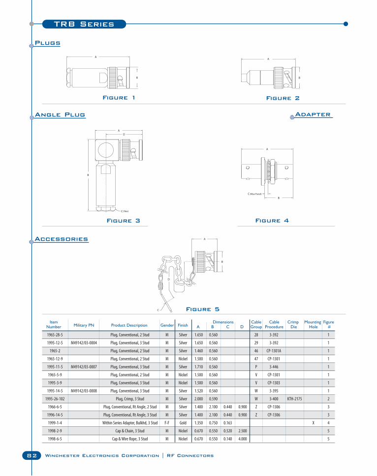
82 Winchester Electronics Corporation | RF Connectors
TRB Series
Figure 1 Figure 2
C
Figure 3
Figure 5
Figure 4
Item Dimensions Cable Cable Crimp Mounting FigureNumber Military PN Product Description Gender Finish A B C D Group Procedure Die Hole #
1965-28-5 Plug, Conventional, 2 Stud M Silver 1.650 0.560 28 3-392 1
1995-12-5 M49142/03-0004 Plug, Conventional, 3 Stud M Silver 1.650 0.560 29 3-392 1
1965-2 Plug, Conventional, 2 Stud M Silver 1.460 0.560 46 CP-1301A 1
1965-12-9 Plug, Conventional, 2 Stud M Nickel 1.500 0.560 47 CP-1301 1
1995-11-5 M49142/03-0007 Plug, Conventional, 3 Stud M Silver 1.710 0.560 P 3-446 1
1965-5-9 Plug, Conventional, 2 Stud M Nickel 1.500 0.560 V CP-1301 1
1995-3-9 Plug, Conventional, 3 Stud M Nickel 1.500 0.560 V CP-1303 1
1995-14-5 M49142/03-0008 Plug, Conventional, 3 Stud M Silver 1.520 0.560 W 3-395 1
1995-26-102 Plug, Crimp, 3 Stud M Silver 2.000 0.590 W 3-400 KTH-2175 2
1966-6-5 Plug, Conventional, Rt Angle, 2 Stud M Silver 1.400 2.100 0.440 0.900 Z CP-1306 3
1996-14-5 Plug, Conventional, Rt Angle, 3 Stud M Silver 1.400 2.100 0.440 0.900 Z CP-1306 3
1999-1-4 Within Series Adapter, Bulkhd, 3 Stud F-F Gold 1.350 0.750 0.163 X 4
1998-2-9 Cap & Chain, 3 Stud M Nickel 0.670 0.550 0.520 2.500 5
1998-6-5 Cap & Wire Rope, 3 Stud M Nickel 0.670 0.550 0.140 4.000 5
Plugs
Angle Plug Adapter
Accessories
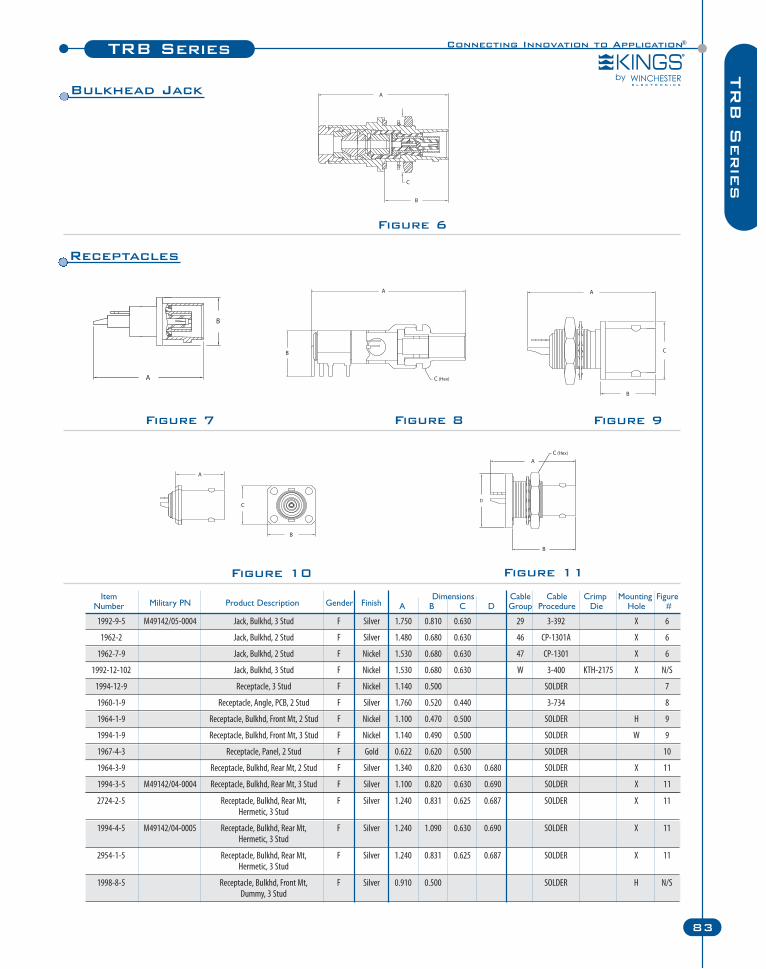
Connecting Innovation to Application®TRB Series
83
TR
B S
erie
s
Figure 7 Figure 8 Figure 9
Figure 10 Figure 11
Figure 6
Item Dimensions Cable Cable Crimp Mounting FigureNumber Military PN Product Description Gender Finish A B C D Group Procedure Die Hole #
1992-9-5 M49142/05-0004 Jack, Bulkhd, 3 Stud F Silver 1.750 0.810 0.630 29 3-392 X 6
1962-2 Jack, Bulkhd, 2 Stud F Silver 1.480 0.680 0.630 46 CP-1301A X 6
1962-7-9 Jack, Bulkhd, 2 Stud F Nickel 1.530 0.680 0.630 47 CP-1301 X 6
1992-12-102 Jack, Bulkhd, 3 Stud F Nickel 1.530 0.680 0.630 W 3-400 KTH-2175 X N/S
1994-12-9 Receptacle, 3 Stud F Nickel 1.140 0.500 SOLDER 7
1960-1-9 Receptacle, Angle, PCB, 2 Stud F Silver 1.760 0.520 0.440 3-734 8
1964-1-9 Receptacle, Bulkhd, Front Mt, 2 Stud F Nickel 1.100 0.470 0.500 SOLDER H 9
1994-1-9 Receptacle, Bulkhd, Front Mt, 3 Stud F Nickel 1.140 0.490 0.500 SOLDER W 9
1967-4-3 Receptacle, Panel, 2 Stud F Gold 0.622 0.620 0.500 SOLDER 10
1964-3-9 Receptacle, Bulkhd, Rear Mt, 2 Stud F Silver 1.340 0.820 0.630 0.680 SOLDER X 11
1994-3-5 M49142/04-0004 Receptacle, Bulkhd, Rear Mt, 3 Stud F Silver 1.100 0.820 0.630 0.690 SOLDER X 11
2724-2-5 Receptacle, Bulkhd, Rear Mt, F Silver 1.240 0.831 0.625 0.687 SOLDER X 11Hermetic, 3 Stud
1994-4-5 M49142/04-0005 Receptacle, Bulkhd, Rear Mt, F Silver 1.240 1.090 0.630 0.690 SOLDER X 11Hermetic, 3 Stud
2954-1-5 Receptacle, Bulkhd, Rear Mt, F Silver 1.240 0.831 0.625 0.687 SOLDER X 11Hermetic, 3 Stud
1998-8-5 Receptacle, Bulkhd, Front Mt, F Silver 0.910 0.500 SOLDER H N/SDummy, 3 Stud
Receptacles
Bulkhead Jack
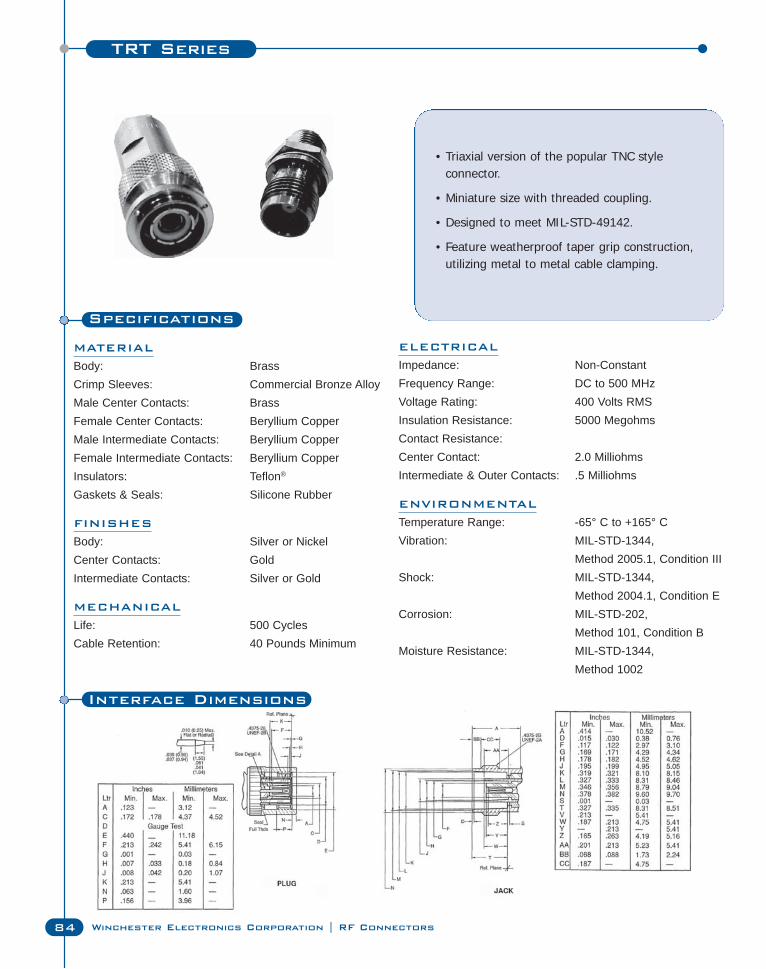
TRT Series
84 Winchester Electronics Corporation | RF Connectors
Specifications
MATERIAL
Body: BrassCrimp Sleeves: Commercial Bronze AlloyMale Center Contacts: BrassFemale Center Contacts: Beryllium CopperMale Intermediate Contacts: Beryllium CopperFemale Intermediate Contacts: Beryllium CopperInsulators: Teflon®
Gaskets & Seals: Silicone Rubber
FINISHES
Body: Silver or NickelCenter Contacts: GoldIntermediate Contacts: Silver or Gold
MECHANICAL
Life: 500 CyclesCable Retention: 40 Pounds Minimum
• Triaxial version of the popular TNC style connector.
• Miniature size with threaded coupling.
• Designed to meet MIL-STD-49142.
• Feature weatherproof taper grip construction,utilizing metal to metal cable clamping.
ELECTRICAL
Impedance: Non-ConstantFrequency Range: DC to 500 MHzVoltage Rating: 400 Volts RMSInsulation Resistance: 5000 MegohmsContact Resistance:Center Contact: 2.0 MilliohmsIntermediate & Outer Contacts: .5 Milliohms
ENVIRONMENTAL
Temperature Range: -65° C to +165° CVibration: MIL-STD-1344,
Method 2005.1, Condition IIIShock: MIL-STD-1344,
Method 2004.1, Condition ECorrosion: MIL-STD-202,
Method 101, Condition BMoisture Resistance: MIL-STD-1344,
Method 1002
Interface Dimensions
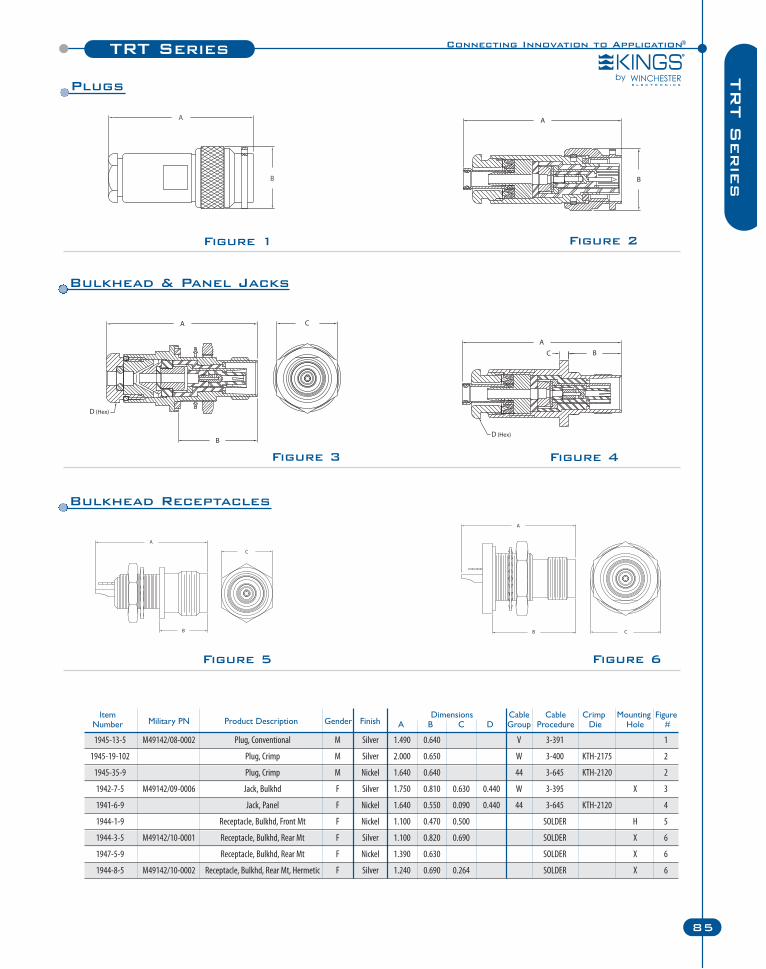
Connecting Innovation to Application®TRT Series
85
TR
T S
erie
s
Figure 4
Figure 1
Figure 3
Figure 5 Figure 6
Figure 2
Item Dimensions Cable Cable Crimp Mounting FigureNumber Military PN Product Description Gender Finish A B C D Group Procedure Die Hole #
1945-13-5 M49142/08-0002 Plug, Conventional M Silver 1.490 0.640 V 3-391 1
1945-19-102 Plug, Crimp M Silver 2.000 0.650 W 3-400 KTH-2175 2
1945-35-9 Plug, Crimp M Nickel 1.640 0.640 44 3-645 KTH-2120 2
1942-7-5 M49142/09-0006 Jack, Bulkhd F Silver 1.750 0.810 0.630 0.440 W 3-395 X 3
1941-6-9 Jack, Panel F Nickel 1.640 0.550 0.090 0.440 44 3-645 KTH-2120 4
1944-1-9 Receptacle, Bulkhd, Front Mt F Nickel 1.100 0.470 0.500 SOLDER H 5
1944-3-5 M49142/10-0001 Receptacle, Bulkhd, Rear Mt F Silver 1.100 0.820 0.690 SOLDER X 6
1947-5-9 Receptacle, Bulkhd, Rear Mt F Nickel 1.390 0.630 SOLDER X 6
1944-8-5 M49142/10-0002 Receptacle, Bulkhd, Rear Mt, Hermetic F Silver 1.240 0.690 0.264 SOLDER X 6
Bulkhead Receptacles
Bulkhead & Panel Jacks
Plugs
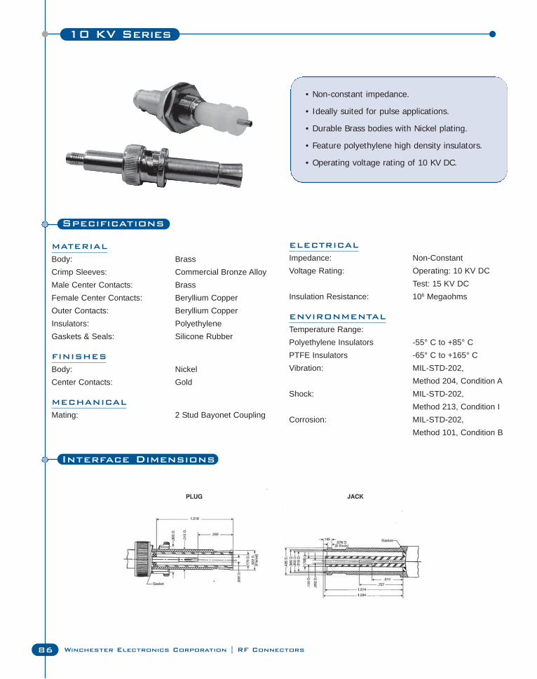
10 KV Series
86 Winchester Electronics Corporation | RF Connectors
Specifications
MATERIAL
Body: BrassCrimp Sleeves: Commercial Bronze AlloyMale Center Contacts: BrassFemale Center Contacts: Beryllium CopperOuter Contacts: Beryllium CopperInsulators: PolyethyleneGaskets & Seals: Silicone Rubber
FINISHES
Body: NickelCenter Contacts: Gold
MECHANICAL
Mating: 2 Stud Bayonet Coupling
• Non-constant impedance.
• Ideally suited for pulse applications.
• Durable Brass bodies with Nickel plating.
• Feature polyethylene high density insulators.
• Operating voltage rating of 10 KV DC.
ELECTRICAL
Impedance: Non-ConstantVoltage Rating: Operating: 10 KV DC
Test: 15 KV DCInsulation Resistance: 106 Megaohms
ENVIRONMENTAL
Temperature Range:Polyethylene Insulators -55° C to +85° CPTFE Insulators -65° C to +165° CVibration: MIL-STD-202,
Method 204, Condition AShock: MIL-STD-202,
Method 213, Condition ICorrosion: MIL-STD-202,
Method 101, Condition B
Interface Dimensions
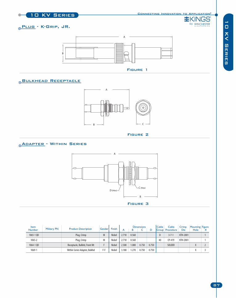
Connecting Innovation to Application®10 KV Series
87
10 K
V S
erie
s
Figure 2
Figure 3
Figure 1
Item Dimensions Cable Cable Crimp Mounting FigureNumber Military PN Product Description Gender Finish A B C D Group Procedure Die Hole #
1065-1 QD Plug, Crimp M Nickel 2.710 0.560 D 3-7-1 KTH-2001 1
1065-2 Plug, Crimp M Nickel 2.710 0.560 40 CP-419 KTH-2001 1
1064-1 QD Receptacle, Bulkhd, Front Mt F Nickel 2.500 1.080 0.750 0.750 SOLDER X 2
1069-1 Within Series Adapter, Bulkhd F-F Nickel 3.180 1.270 0.750 0.750 X 3
Plug - K-Grip, JR.
Bulkhead Receptacle
Adapter - Within Series
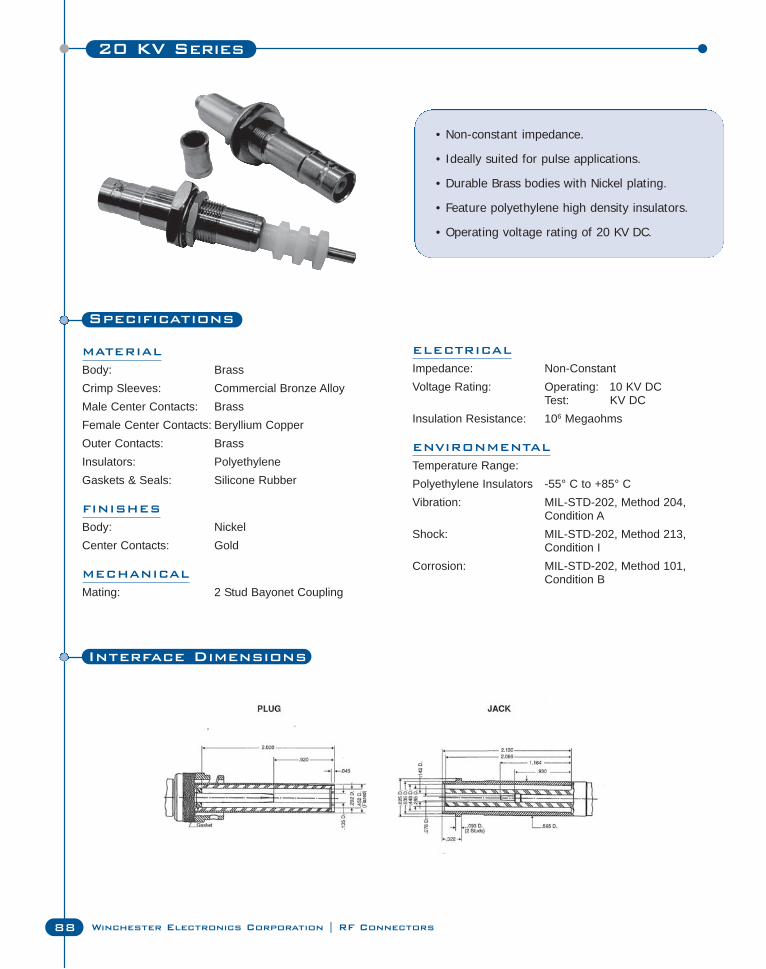
20 KV Series
88 Winchester Electronics Corporation | RF Connectors
Specifications
MATERIAL
Body: BrassCrimp Sleeves: Commercial Bronze AlloyMale Center Contacts: BrassFemale Center Contacts: Beryllium CopperOuter Contacts: BrassInsulators: PolyethyleneGaskets & Seals: Silicone Rubber
FINISHES
Body: NickelCenter Contacts: Gold
MECHANICAL
Mating: 2 Stud Bayonet Coupling
• Non-constant impedance.
• Ideally suited for pulse applications.
• Durable Brass bodies with Nickel plating.
• Feature polyethylene high density insulators.
• Operating voltage rating of 20 KV DC.
ELECTRICAL
Impedance: Non-ConstantVoltage Rating: Operating: 10 KV DC
Test: KV DCInsulation Resistance: 106 Megaohms
ENVIRONMENTAL
Temperature Range:Polyethylene Insulators -55° C to +85° CVibration: MIL-STD-202, Method 204,
Condition AShock: MIL-STD-202, Method 213,
Condition ICorrosion: MIL-STD-202, Method 101,
Condition B
Interface Dimensions
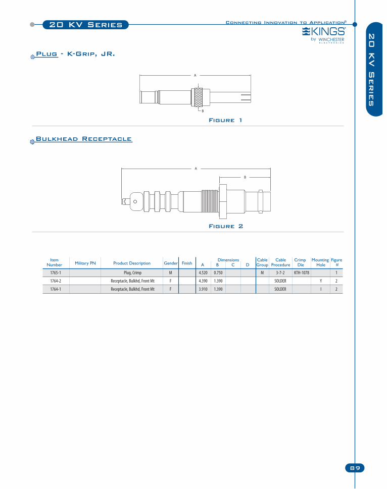
1765-1 Plug, Crimp M 4.520 0.750 M 3-7-2 KTH-1078 1
1764-2 Receptacle, Bulkhd, Front Mt F 4.390 1.390 SOLDER Y 2
1764-1 Receptacle, Bulkhd, Front Mt F 3.910 1.390 SOLDER I 2
Connecting Innovation to Application®20 KV Series
89
20 K
V S
erie
s
Figure 2
Figure 1
Item Dimensions Cable Cable Crimp Mounting FigureNumber Military PN Product Description Gender Finish A B C D Group Procedure Die Hole #
Plug - K-Grip, JR.
Bulkhead Receptacle
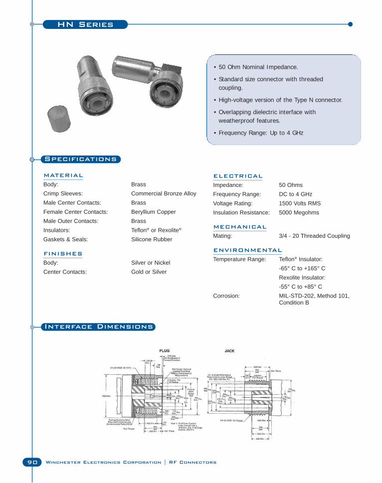
HN Series
90 Winchester Electronics Corporation | RF Connectors
Specifications
MATERIAL
Body: BrassCrimp Sleeves: Commercial Bronze AlloyMale Center Contacts: BrassFemale Center Contacts: Beryllium CopperMale Outer Contacts: BrassInsulators: Teflon® or Rexolite®
Gaskets & Seals: Silicone Rubber
FINISHES
Body: Silver or NickelCenter Contacts: Gold or Silver
• 50 Ohm Nominal Impedance.
• Standard size connector with threaded coupling.
• High-voltage version of the Type N connector.
• Overlapping dielectric interface with weatherproof features.
• Frequency Range: Up to 4 GHz
ELECTRICAL
Impedance: 50 OhmsFrequency Range: DC to 4 GHzVoltage Rating: 1500 Volts RMSInsulation Resistance: 5000 Megohms
MECHANICAL
Mating: 3/4 - 20 Threaded Coupling
ENVIRONMENTAL
Temperature Range: Teflon® Insulator: -65° C to +165° CRexolite Insulator: -55° C to +85° C
Corrosion: MIL-STD-202, Method 101, Condition B
Interface Dimensions
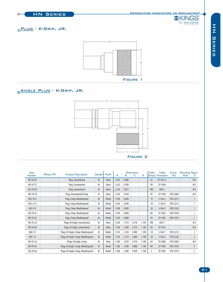
Connecting Innovation to Application®
91
Figure 2
Figure 1
HN SeriesH
N S
erie
s
Item Dimensions Cable Cable Crimp Mounting FigureNumber Military PN Product Description Gender Finish A B C D Group Procedure Die Hole #
KH-59-05 Plug, Conventional M Silver 1.610 0.880 G1 CP-1021.3 N/S
KH-59-72 Plug, Conventional M Silver 1.625 0.500 DE CP-1004 N/S
UG-59 E/U Plug, Conventional M Silver 2.218 0.875 MN 60D-5 N/S
KH-59-78 Plug, Conventional/Crimp M Silver 2.230 0.450 N1 CP-239A KTH-2004 N/S
845-10-9 Plug, Crimp, Weatherproof M Nickel 1.930 0.890 19 3-546-2 KTH-2213 1
845-13-9 Plug, Crimp, Weatherproof M Nickel 1.830 0.890 18 3-546-4 KTH-2212 1
845-9-9 Plug, Crimp, Weatherproof M Nickel 1.890 0.890 20 3-546-2 KTH-2229 1
KH-59-63 Plug, Crimp, Weatherproof M Nickel 1.930 0.880 M1 CP-5403 KTH-1078 1
KH-59-65 Plug, Crimp, Weatherproof M Nickel 1.930 0.880 N1 CP-5403 KTH-1079 1
KH-59-26 Plugs, Rt Angle, Conventional M Silver 1.560 2.370 0.750 1.190 MN 60D-5 N/S
KH-59-84 Plugs, Rt Angle, Conventional M Silver 1.540 2.380 0.750 1.190 N3 CP-1031 N/S
846-5-9 Plugs, Rt Angle, Crimp, Weatherproof M Nickel 1.510 2.250 0.880 1.190 18 3-546-7 KTH-2212 2
846-7-9 Plugs, Rt Angle, Crimp, Weatherproof M Nickel 1.550 2.310 0.880 1.190 20 3-546-2 KTH-2229 2
KH-59-24 Plugs, Rt Angle, Crimp M Silver 1.500 2.810 0.750 1.180 N1 CP-208A KTH-2004 N/S
KH-59-64 Plugs, Rt Angle, Crimp, Weatherproof M Nickel 1.500 2.400 0.880 1.190 M1 CP-5403 KTH-1078 2
KH-59-66 Plugs, Rt Angle, Crimp, Weatherproof M Nickel 1.500 2.400 0.690 1.190 2 CP-5403 KTH-1079 2
Plug - K-Grip, JR.
Angle Plug - K-Grip, JR.
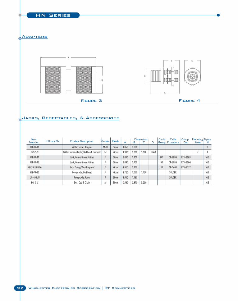
HN Series
92 Winchester Electronics Corporation | RF Connectors
Figure 3 Figure 4
Item Dimensions Cable Cable Crimp Mounting FigureNumber Military PN Product Description Gender Finish A B C D Group Procedure Die Hole #
KH-99-10 Within Series Adapter M-M Silver 1.850 0.880 3
849-5-9 Within Series Adapter, Bulkhead, Hermetic F-F Nickel 1.930 1.060 1.060 1.060 Z 4
KH-39-11 Jack, Conventional/Crimp F Silver 2.050 0.750 M1 CP-208A KTH-2003 N/S
KH-39-12 Jack, Conventional/Crimp F Silver 2.040 0.750 N1 CP-208A KTH-2004 N/S
KH-39-25 M06 Jack, Crimp, Weatherproof F Nickel 1.910 0.750 12 CP-5403 KTH-2127 N/S
KH-79-15 Receptacle, Bulkhead F Nickel 1.720 1.060 1.130 SOLDER N/S
UG-496 /U Receptacle, Panel F Silver 1.530 1.180 SOLDER N/S
848-3-5 Dust Cap & Chain M Silver 0.560 0.875 3.250 N/S
Adapters
Jacks, Receptacles, & Accessories
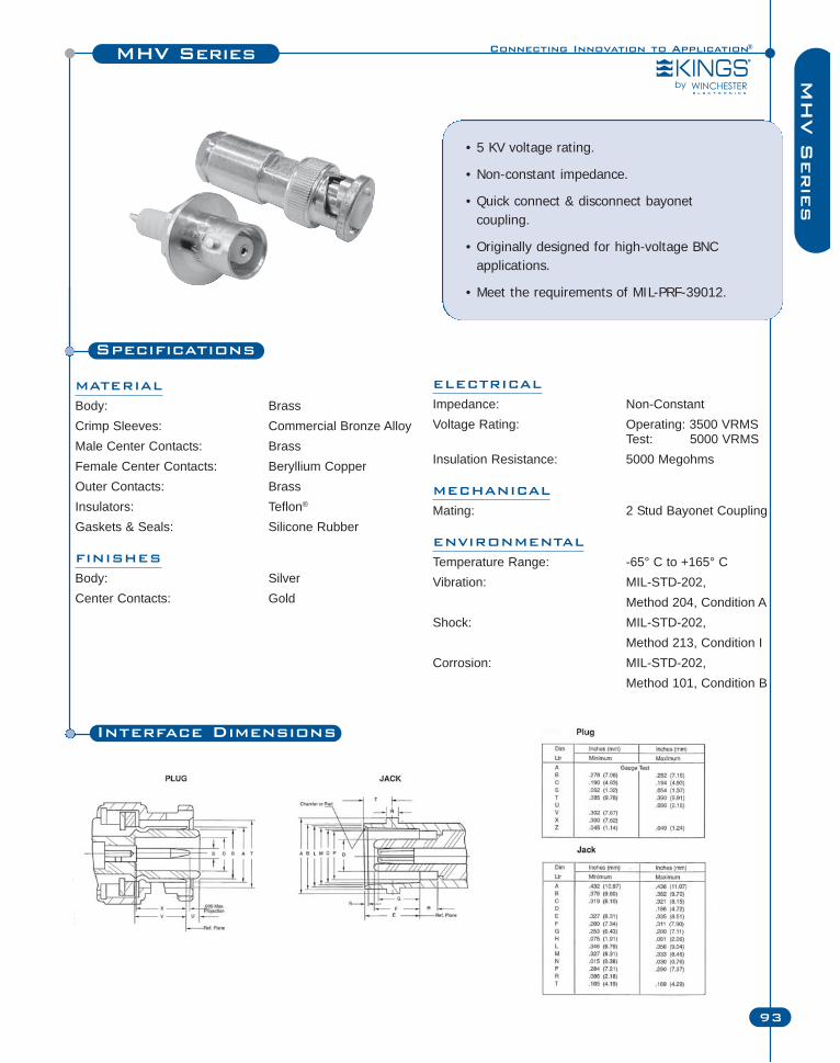
Specifications
MATERIAL
Body: BrassCrimp Sleeves: Commercial Bronze AlloyMale Center Contacts: BrassFemale Center Contacts: Beryllium CopperOuter Contacts: BrassInsulators: Teflon®
Gaskets & Seals: Silicone Rubber
FINISHES
Body: SilverCenter Contacts: Gold
• 5 KV voltage rating.
• Non-constant impedance.
• Quick connect & disconnect bayonet coupling.
• Originally designed for high-voltage BNCapplications.
• Meet the requirements of MIL-PRF-39012.
Connecting Innovation to Application®MHV Series
93
MH
V S
erie
s
ELECTRICAL
Impedance: Non-ConstantVoltage Rating: Operating: 3500 VRMS
Test: 5000 VRMSInsulation Resistance: 5000 Megohms
MECHANICAL
Mating: 2 Stud Bayonet Coupling
ENVIRONMENTAL
Temperature Range: -65° C to +165° CVibration: MIL-STD-202,
Method 204, Condition AShock: MIL-STD-202,
Method 213, Condition ICorrosion: MIL-STD-202,
Method 101, Condition B
Interface Dimensions
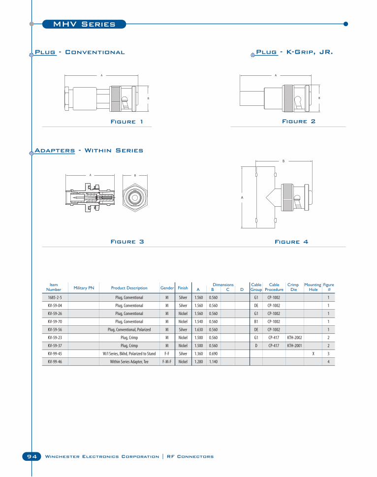
MHV Series
94 Winchester Electronics Corporation | RF Connectors
Figure 2Figure 1
Figure 3 Figure 4
Item Dimensions Cable Cable Crimp Mounting FigureNumber Military PN Product Description Gender Finish A B C D Group Procedure Die Hole #
1685-2-5 Plug, Conventional M Silver 1.560 0.560 G1 CP-1002 1
KV-59-04 Plug, Conventional M Silver 1.560 0.560 DE CP-1002 1
KV-59-26 Plug, Conventional M Nickel 1.560 0.560 G1 CP-1002 1
KV-59-70 Plug, Conventional M Nickel 1.540 0.560 B1 CP-1002 1
KV-59-56 Plug, Conventional, Polarized M Silver 1.630 0.560 DE CP-1002 1
KV-59-23 Plug, Crimp M Nickel 1.500 0.560 G1 CP-417 KTH-2002 2
KV-59-37 Plug, Crimp M Nickel 1.500 0.560 D CP-417 KTH-2001 2
KV-99-45 W/I Series, Bkhd, Polarized to Stand F-F Silver 1.360 0.690 X 3
KV-99-46 Within Series Adapter, Tee F-M-F Nickel 1.280 1.140 4
Plug - Conventional Plug - K-Grip, JR.
Adapters - Within Series
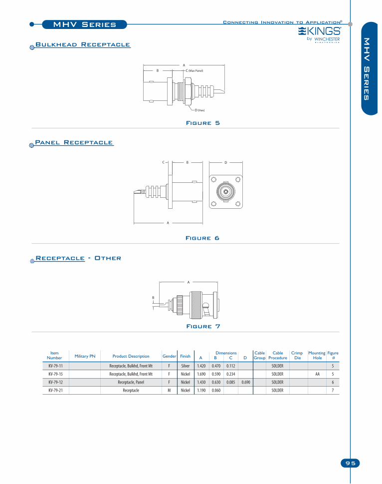
Connecting Innovation to Application®MHV Series
95
MH
V S
erie
s
Item Dimensions Cable Cable Crimp Mounting FigureNumber Military PN Product Description Gender Finish A B C D Group Procedure Die Hole #
KV-79-11 Receptacle, Bulkhd, Front Mt F Silver 1.420 0.470 0.112 SOLDER 5
KV-79-15 Receptacle, Bulkhd, Front Mt F Nickel 1.690 0.590 0.234 SOLDER AA 5
KV-79-12 Receptacle, Panel F Nickel 1.430 0.630 0.085 0.690 SOLDER 6
KV-79-21 Receptacle M Nickel 1.190 0.060 SOLDER 7
Figure 7
Figure 6
Figure 5
Receptacle - Other
Panel Receptacle
Bulkhead Receptacle
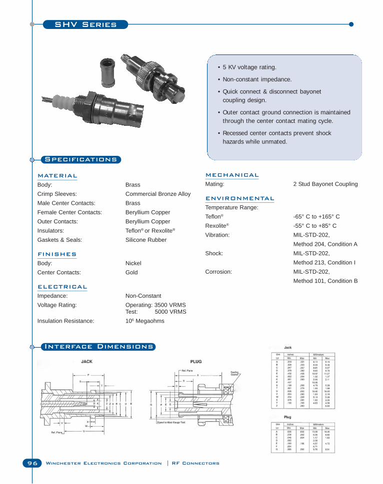
SHV Series
96 Winchester Electronics Corporation | RF Connectors
Specifications
MATERIAL
Body: BrassCrimp Sleeves: Commercial Bronze AlloyMale Center Contacts: BrassFemale Center Contacts: Beryllium CopperOuter Contacts: Beryllium CopperInsulators: Teflon® or Rexolite®
Gaskets & Seals: Silicone Rubber
FINISHES
Body: NickelCenter Contacts: Gold
ELECTRICAL
Impedance: Non-ConstantVoltage Rating: Operating: 3500 VRMS
Test: 5000 VRMSInsulation Resistance: 106 Megaohms
• 5 KV voltage rating.
• Non-constant impedance.
• Quick connect & disconnect bayonet coupling design.
• Outer contact ground connection is maintainedthrough the center contact mating cycle.
• Recessed center contacts prevent shock hazards while unmated.
MECHANICAL
Mating: 2 Stud Bayonet Coupling
ENVIRONMENTAL
Temperature Range:Teflon® -65° C to +165° CRexolite® -55° C to +85° CVibration: MIL-STD-202,
Method 204, Condition AShock: MIL-STD-202,
Method 213, Condition ICorrosion: MIL-STD-202,
Method 101, Condition B
Interface Dimensions
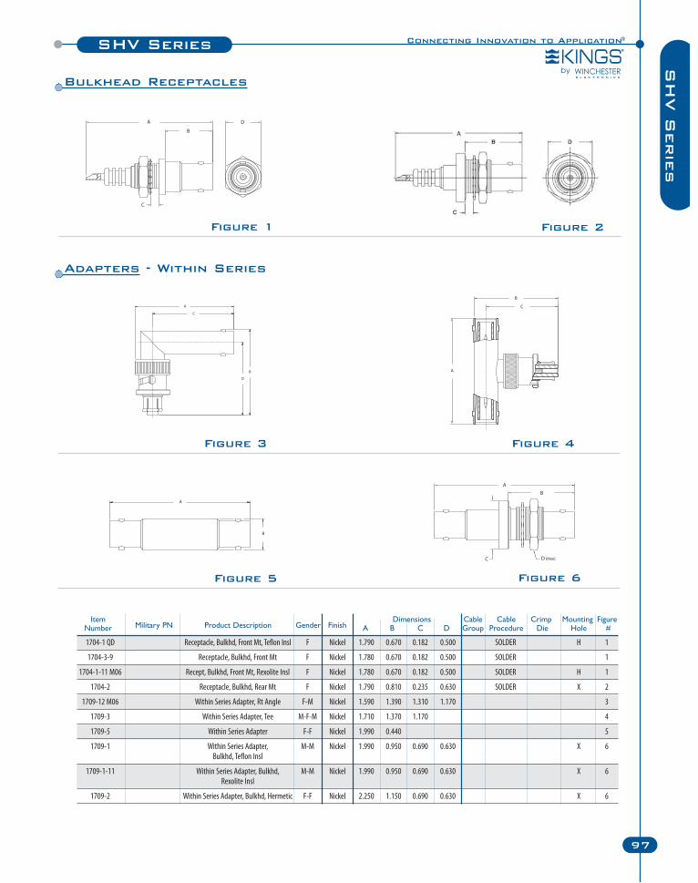
Connecting Innovation to Application®SHV Series
97
SH
V S
erie
s
Figure 5
Figure 3 Figure 4
Figure 6
Figure 1 Figure 2
Item Dimensions Cable Cable Crimp Mounting FigureNumber Military PN Product Description Gender Finish A B C D Group Procedure Die Hole #
1704-1 QD Receptacle, Bulkhd, Front Mt, Teflon Insl F Nickel 1.790 0.670 0.182 0.500 SOLDER H 1
1704-3-9 Receptacle, Bulkhd, Front Mt F Nickel 1.780 0.670 0.182 0.500 SOLDER 1
1704-1-11 M06 Recept, Bulkhd, Front Mt, Rexolite Insl F Nickel 1.780 0.670 0.182 0.500 SOLDER H 1
1704-2 Receptacle, Bulkhd, Rear Mt F Nickel 1.790 0.810 0.235 0.630 SOLDER X 2
1709-12 M06 Within Series Adapter, Rt Angle F-M Nickel 1.590 1.390 1.310 1.170 3
1709-3 Within Series Adapter, Tee M-F-M Nickel 1.710 1.370 1.170 4
1709-5 Within Series Adapter F-F Nickel 1.990 0.440 5
1709-1 Within Series Adapter, M-M Nickel 1.990 0.950 0.690 0.630 X 6Bulkhd, Teflon Insl
1709-1-11 Within Series Adapter, Bulkhd, M-M Nickel 1.990 0.950 0.690 0.630 X 6Rexolite Insl
1709-2 Within Series Adapter, Bulkhd, Hermetic F-F Nickel 2.250 1.150 0.690 0.630 X 6
Bulkhead Receptacles
Adapters - Within Series
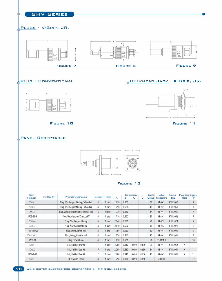
SHV Series
98 Winchester Electronics Corporation | RF Connectors
Figure 10
Figure 9Figure 8Figure 7
Figure 11
Figure 12
1705-1 Plug, Weatherproof Crimp, Teflon Insl M Nickel 1.830 0.560 G1 CP-441 KTH-2062 7
1705-2 Plug, Weatherproof Crimp, Teflon Insl M Nickel 1.750 0.560 D CP-441 KTH-2061 7
1705-2-1 Plug, Weatherproof Crimp, Rexolite Insl M Nickel 1.730 0.560 D CP-441 KTH-2061 7
1705-21-9 Plug, Weatherproof Crimp, 6KV M Nickel 1.710 0.560 G1 CP-441 KTH-2062 7
1705-4 Plug, Weatherproof Crimp M Nickel 2.140 0.630 N1 CP-457 KTH-1079 7
1705-3 Plug, Weatherproof Crimp M Nickel 2.010 0.560 B1 CP-447 KTH-2071 8
1705-16 M06 Plug, Crimp, Teflon Insl M Nickel 1.790 0.560 40 CP-441 KTH-2001 9
1705-16-11 Plug, Crimp, Rexolite Insl M Nickel 1.770 0.560 40 CP-441 KTH-2001 9
1705-14 Plug, Conventional M Nickel 1.810 0.560 G1 CP-1001.3 10
1702-1 Jack, Bulkhd, Rear Mt F Nickel 2.200 0.810 0.690 0.630 G1 CP-441 KTH-2062 X 11
1702-2 Jack, Bulkhd, Rear Mt F Nickel 2.200 0.810 0.690 0.630 D CP-441 KTH-2061 X 11
1702-4-11 Jack, Bulkhd, Rear Mt F Nickel 2.200 0.810 0.690 0.630 40 CP-441 KTH-2001 X 11
1707-1 Receptacle, Panel M Nickel 1.790 0.870 0.090 0.690 SOLDER 12
Item Dimensions Cable Cable Crimp Mounting FigureNumber Military PN Product Description Gender Finish A B C D Group Procedure Die Hole #
Plugs - K-Grip, JR.
Plug - Conventional Bulkhead Jack - K-Grip, JR.
Panel Receptacle
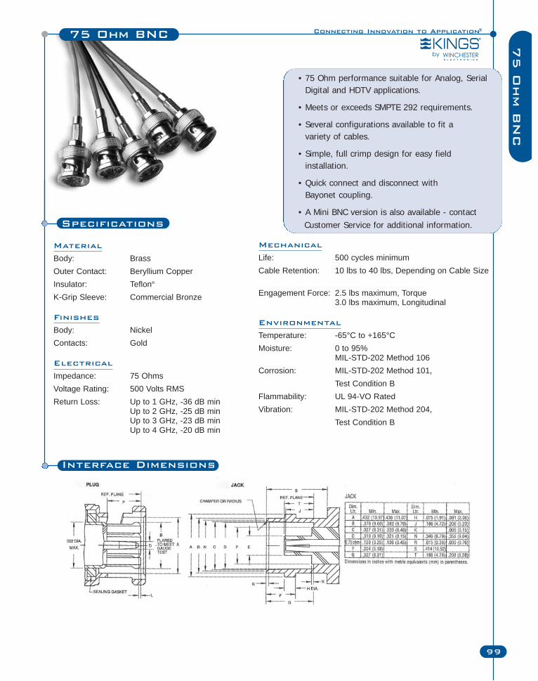
Connecting Innovation to Application®75 Ohm BNC
99
75 O
hm B
NC
Material
Body: BrassOuter Contact: Beryllium CopperInsulator: Teflon®
K-Grip Sleeve: Commercial Bronze
Finishes
Body: NickelContacts: Gold
Electrical
Impedance: 75 OhmsVoltage Rating: 500 Volts RMSReturn Loss: Up to 1 GHz, -36 dB min
Up to 2 GHz, -25 dB minUp to 3 GHz, -23 dB minUp to 4 GHz, -20 dB min
• 75 Ohm performance suitable for Analog, SerialDigital and HDTV applications.
• Meets or exceeds SMPTE 292 requirements.
• Several configurations available to fit a variety of cables.
• Simple, full crimp design for easy fieldinstallation.
• Quick connect and disconnect with Bayonet coupling.
• A Mini BNC version is also available - contactCustomer Service for additional information.
Mechanical
Life: 500 cycles minimumCable Retention: 10 lbs to 40 lbs, Depending on Cable Size
Engagement Force: 2.5 lbs maximum, Torque3.0 lbs maximum, Longitudinal
Environmental
Temperature: -65°C to +165°CMoisture: 0 to 95%
MIL-STD-202 Method 106Corrosion: MIL-STD-202 Method 101,
Test Condition BFlammability: UL 94-VO RatedVibration: MIL-STD-202 Method 204,
Test Condition B
Interface Dimensions
Specifications
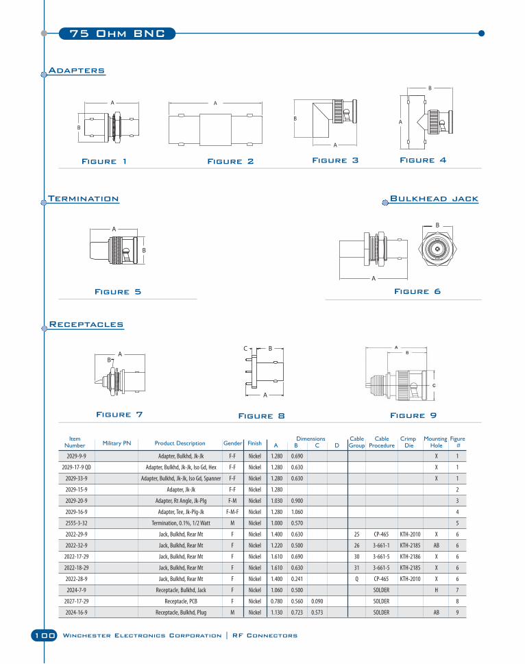
100 Winchester Electronics Corporation | RF Connectors
75 Ohm BNC
Figure 1 Figure 2 Figure 4Figure 3
Figure 5 Figure 6
Item Dimensions Cable Cable Crimp Mounting FigureNumber Military PN Product Description Gender Finish A B C D Group Procedure Die Hole #
2029-9-9 Adapter, Bulkhd, Jk-Jk F-F Nickel 1.280 0.690 X 1
2029-17-9 QD Adapter, Bulkhd, Jk-Jk, Iso Gd, Hex F-F Nickel 1.280 0.630 X 1
2029-33-9 Adapter, Bulkhd, Jk-Jk, Iso Gd, Spanner F-F Nickel 1.280 0.630 X 1
2029-15-9 Adapter, Jk-Jk F-F Nickel 1.280 2
2029-20-9 Adapter, Rt Angle, Jk-Plg F-M Nickel 1.030 0.900 3
2029-16-9 Adapter, Tee, Jk-Plg-Jk F-M-F Nickel 1.280 1.060 4
2555-3-32 Termination, 0.1%, 1/2 Watt M Nickel 1.000 0.570 5
2022-29-9 Jack, Bulkhd, Rear Mt F Nickel 1.400 0.630 25 CP-465 KTH-2010 X 6
2022-32-9 Jack, Bulkhd, Rear Mt F Nickel 1.220 0.500 26 3-661-1 KTH-2185 AB 6
2022-17-29 Jack, Bulkhd, Rear Mt F Nickel 1.610 0.690 30 3-661-5 KTH-2186 X 6
2022-18-29 Jack, Bulkhd, Rear Mt F Nickel 1.610 0.630 31 3-661-5 KTH-2185 X 6
2022-28-9 Jack, Bulkhd, Rear Mt F Nickel 1.400 0.241 Q CP-465 KTH-2010 X 6
2024-7-9 Receptacle, Bulkhd, Jack F Nickel 1.060 0.500 SOLDER H 7
2027-17-29 Receptacle, PCB F Nickel 0.780 0.560 0.090 SOLDER 8
2024-16-9 Receptacle, Bulkhd, Plug M Nickel 1.130 0.723 0.573 SOLDER AB 9
Figure 7 Figure 8 Figure 9
Adapters
Termination Bulkhead jack
Receptacles
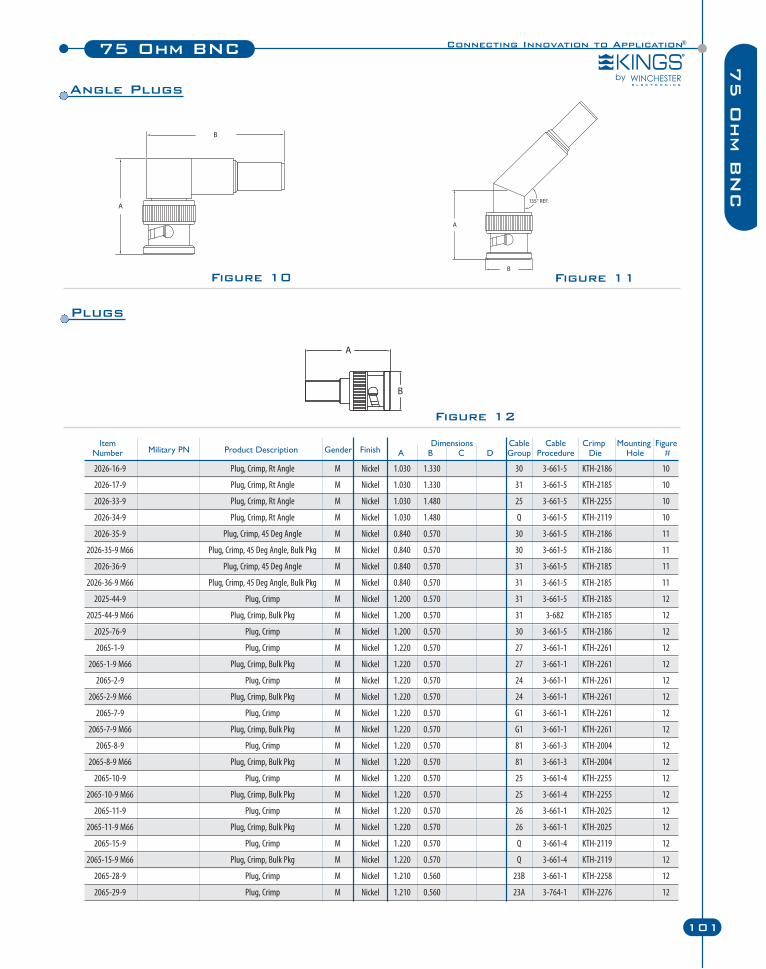
Figure 11
Connecting Innovation to Application®75 Ohm BNC
101
75 O
hm B
NC
Figure 10
Figure 12
Item Dimensions Cable Cable Crimp Mounting FigureNumber Military PN Product Description Gender Finish A B C D Group Procedure Die Hole #
2026-16-9 Plug, Crimp, Rt Angle M Nickel 1.030 1.330 30 3-661-5 KTH-2186 10
2026-17-9 Plug, Crimp, Rt Angle M Nickel 1.030 1.330 31 3-661-5 KTH-2185 10
2026-33-9 Plug, Crimp, Rt Angle M Nickel 1.030 1.480 25 3-661-5 KTH-2255 10
2026-34-9 Plug, Crimp, Rt Angle M Nickel 1.030 1.480 Q 3-661-5 KTH-2119 10
2026-35-9 Plug, Crimp, 45 Deg Angle M Nickel 0.840 0.570 30 3-661-5 KTH-2186 11
2026-35-9 M66 Plug, Crimp, 45 Deg Angle, Bulk Pkg M Nickel 0.840 0.570 30 3-661-5 KTH-2186 11
2026-36-9 Plug, Crimp, 45 Deg Angle M Nickel 0.840 0.570 31 3-661-5 KTH-2185 11
2026-36-9 M66 Plug, Crimp, 45 Deg Angle, Bulk Pkg M Nickel 0.840 0.570 31 3-661-5 KTH-2185 11
2025-44-9 Plug, Crimp M Nickel 1.200 0.570 31 3-661-5 KTH-2185 12
2025-44-9 M66 Plug, Crimp, Bulk Pkg M Nickel 1.200 0.570 31 3-682 KTH-2185 12
2025-76-9 Plug, Crimp M Nickel 1.200 0.570 30 3-661-5 KTH-2186 12
2065-1-9 Plug, Crimp M Nickel 1.220 0.570 27 3-661-1 KTH-2261 12
2065-1-9 M66 Plug, Crimp, Bulk Pkg M Nickel 1.220 0.570 27 3-661-1 KTH-2261 12
2065-2-9 Plug, Crimp M Nickel 1.220 0.570 24 3-661-1 KTH-2261 12
2065-2-9 M66 Plug, Crimp, Bulk Pkg M Nickel 1.220 0.570 24 3-661-1 KTH-2261 12
2065-7-9 Plug, Crimp M Nickel 1.220 0.570 G1 3-661-1 KTH-2261 12
2065-7-9 M66 Plug, Crimp, Bulk Pkg M Nickel 1.220 0.570 G1 3-661-1 KTH-2261 12
2065-8-9 Plug, Crimp M Nickel 1.220 0.570 81 3-661-3 KTH-2004 12
2065-8-9 M66 Plug, Crimp, Bulk Pkg M Nickel 1.220 0.570 81 3-661-3 KTH-2004 12
2065-10-9 Plug, Crimp M Nickel 1.220 0.570 25 3-661-4 KTH-2255 12
2065-10-9 M66 Plug, Crimp, Bulk Pkg M Nickel 1.220 0.570 25 3-661-4 KTH-2255 12
2065-11-9 Plug, Crimp M Nickel 1.220 0.570 26 3-661-1 KTH-2025 12
2065-11-9 M66 Plug, Crimp, Bulk Pkg M Nickel 1.220 0.570 26 3-661-1 KTH-2025 12
2065-15-9 Plug, Crimp M Nickel 1.220 0.570 Q 3-661-4 KTH-2119 12
2065-15-9 M66 Plug, Crimp, Bulk Pkg M Nickel 1.220 0.570 Q 3-661-4 KTH-2119 12
2065-28-9 Plug, Crimp M Nickel 1.210 0.560 23B 3-661-1 KTH-2258 12
2065-29-9 Plug, Crimp M Nickel 1.210 0.560 23A 3-764-1 KTH-2276 12
Plugs
Angle Plugs
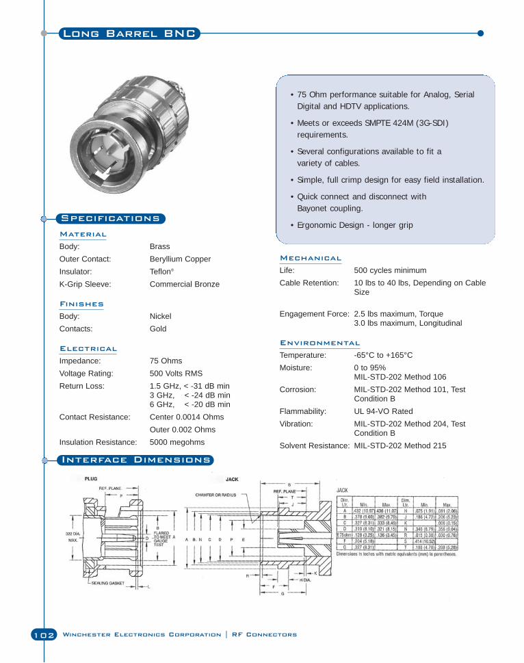
Long Barrel BNC
102 Winchester Electronics Corporation | RF Connectors
Specifications
Material
Body: BrassOuter Contact: Beryllium CopperInsulator: Teflon®
K-Grip Sleeve: Commercial Bronze
Finishes
Body: NickelContacts: Gold
Electrical
Impedance: 75 OhmsVoltage Rating: 500 Volts RMSReturn Loss: 1.5 GHz, < -31 dB min
3 GHz, < -24 dB min6 GHz, < -20 dB min
Contact Resistance: Center 0.0014 OhmsOuter 0.002 Ohms
Insulation Resistance: 5000 megohms
• 75 Ohm performance suitable for Analog, SerialDigital and HDTV applications.
• Meets or exceeds SMPTE 424M (3G-SDI)requirements.
• Several configurations available to fit a variety of cables.
• Simple, full crimp design for easy field installation.
• Quick connect and disconnect with Bayonet coupling.
• Ergonomic Design - longer grip
Interface Dimensions
Mechanical
Life: 500 cycles minimumCable Retention: 10 lbs to 40 lbs, Depending on Cable
Size
Engagement Force: 2.5 lbs maximum, Torque3.0 lbs maximum, Longitudinal
Environmental
Temperature: -65°C to +165°CMoisture: 0 to 95%
MIL-STD-202 Method 106Corrosion: MIL-STD-202 Method 101, Test
Condition BFlammability: UL 94-VO RatedVibration: MIL-STD-202 Method 204, Test
Condition BSolvent Resistance: MIL-STD-202 Method 215
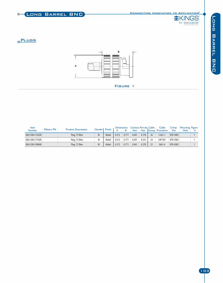
Connecting Innovation to Application®Long Barrel BNC
103
Long B
arrel B
NC
Figure 1
Plugs
Item Dimensions Contact Ferrule Cable Cable Crimp Mounting FigureNumber Military PN Product Description Gender Finish A B Hex Hex Group Procedure Die Hole #
2065-E00-C7202N Plug, 75 Ohm M Nickel 0.572 0.771 0.041 0.178 26 3-661-1 KTH-5003 1
2065-E00-C7102N Plug, 75 Ohm M Nickel 0.572 0.771 0.041 0.255 24 CAP-E01 KTH-5003 1
2065-E00-C9004N Plug, 75 Ohm M Nickel 0.572 0.771 0.041 0.278 25 3661-4 KTH-5003 1
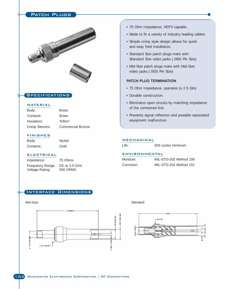
Patch Plugs
104 Winchester Electronics Corporation | RF Connectors
Specifications
MATERIAL
Body: BrassContacts: BrassInsulators: Teflon®
Crimp Sleeves: Commercial Bronze
FINISHES
Body: NickelContacts: Gold
ELECTRICAL
Impedance: 75 OhmsFrequency Range: DC to 2.5 GHzVoltage Rating: 500 VRMS
• 75 Ohm Impedance, HDTV capable.
• Made to fit a variety of industry leading cables.
• Simple crimp style design allows for quick and easy field installation.
• Standard Size patch plugs mate with Standard Size video jacks (.090( Pin Size)
• Mid-Size patch plugs mate with Mid-Size video jacks (.050( Pin Size)
PATCH PLUG TERMINATION
• 75 Ohm Impedance, operates to 2.5 GHz.
• Durable construction.
• Eliminates open circuits by matching impedanceof the connected line.
• Prevents signal reflection and possible associatedequipment malfunction.
MECHANICAL
Life: 500 cycles minimum
ENVIRONMENTAL
Moisture: MIL-STD-202 Method 106Corrosion: MIL-STD-202 Method 101
Interface Dimensions
StandardMid-Size
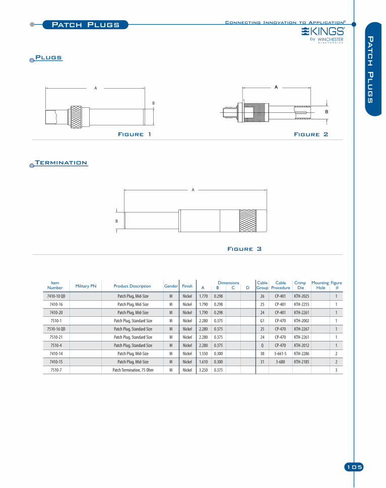
Item Dimensions Cable Cable Crimp Mounting FigureNumber Military PN Product Description Gender Finish A B C D Group Procedure Die Hole #
7410-10 QD Patch Plug, Mid-Size M Nickel 1.770 0.298 26 CP-401 KTH-2025 1
7410-16 Patch Plug, Mid-Size M Nickel 1.790 0.298 25 CP-401 KTH-2255 1
7410-20 Patch Plug, Mid-Size M Nickel 1.790 0.298 24 CP-401 KTH-2261 1
7510-1 Patch Plug, Standard Size M Nickel 2.280 0.375 G1 CP-470 KTH-2002 1
7510-16 QD Patch Plug, Standard Size M Nickel 2.280 0.375 25 CP-470 KTH-2267 1
7510-21 Patch Plug, Standard Size M Nickel 2.280 0.375 24 CP-470 KTH-2261 1
7510-4 Patch Plug, Standard Size M Nickel 2.280 0.375 Q CP-470 KTH-2012 1
7410-14 Patch Plug, Mid-Size M Nickel 1.550 0.300 30 3-661-5 KTH-2286 2
7410-15 Patch Plug, Mid-Size M Nickel 1.610 0.300 31 3-680 KTH-2185 2
7510-7 Patch Termination, 75 Ohm M Nickel 3.250 0.375 3
Connecting Innovation to Application®Patch Plugs
105
Patch P
lugs
Figure 3
Figure 1 Figure 2
Plugs
Termination
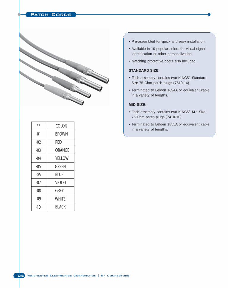
• Pre-assembled for quick and easy installation.
• Available in 10 popular colors for visual signalidentification or other personalization.
• Matching protective boots also included.
STANDARD SIZE:
• Each assembly contains two KINGS® StandardSize 75 Ohm patch plugs (7510-16).
• Terminated to Belden 1694A or equivalent cablein a variety of lengths.
MID-SIZE:
• Each assembly contains two KINGS® Mid-Size 75 Ohm patch plugs (7410-10).
• Terminated to Belden 1855A or equivalent cablein a variety of lengths.
Patch Cords
106 Winchester Electronics Corporation | RF Connectors
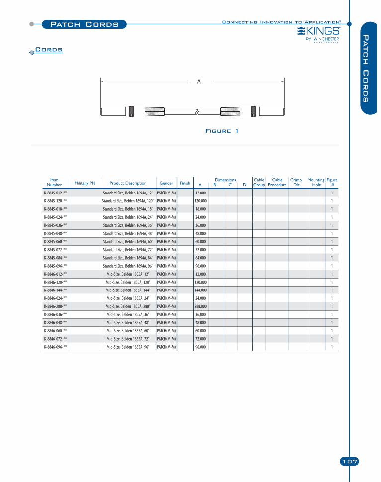
Connecting Innovation to Application®Patch Cords
107
Patch C
ords
Figure 1
Item Dimensions Cable Cable Crimp Mounting FigureNumber Military PN Product Description Gender Finish A B C D Group Procedure Die Hole #
K-8845-012-** Standard Size, Belden 1694A, 12" PATCH(M-M) 12.000 1
K-8845-120-** Standard Size, Belden 1694A, 120" PATCH(M-M) 120.000 1
K-8845-018-** Standard Size, Belden 1694A, 18" PATCH(M-M) 18.000 1
K-8845-024-** Standard Size, Belden 1694A, 24" PATCH(M-M) 24.000 1
K-8845-036-** Standard Size, Belden 1694A, 36" PATCH(M-M) 36.000 1
K-8845-048-** Standard Size, Belden 1694A, 48" PATCH(M-M) 48.000 1
K-8845-060-** Standard Size, Belden 1694A, 60" PATCH(M-M) 60.000 1
K-8845-072-** Standard Size, Belden 1694A, 72" PATCH(M-M) 72.000 1
K-8845-084-** Standard Size, Belden 1694A, 84" PATCH(M-M) 84.000 1
K-8845-096-** Standard Size, Belden 1694A, 96" PATCH(M-M) 96.000 1
K-8846-012-** Mid-Size, Belden 1855A, 12" PATCH(M-M) 12.000 1
K-8846-120-** Mid-Size, Belden 1855A, 120" PATCH(M-M) 120.000 1
K-8846-144-** Mid-Size, Belden 1855A, 144" PATCH(M-M) 144.000 1
K-8846-024-** Mid-Size, Belden 1855A, 24" PATCH(M-M) 24.000 1
K-8846-288-** Mid-Size, Belden 1855A, 288" PATCH(M-M) 288.000 1
K-8846-036-** Mid-Size, Belden 1855A, 36" PATCH(M-M) 36.000 1
K-8846-048-** Mid-Size, Belden 1855A, 48" PATCH(M-M) 48.000 1
K-8846-060-** Mid-Size, Belden 1855A, 60" PATCH(M-M) 60.000 1
K-8846-072-** Mid-Size, Belden 1855A, 72" PATCH(M-M) 72.000 1
K-8846-096-** Mid-Size, Belden 1855A, 96" PATCH(M-M) 96.000 1
Cords
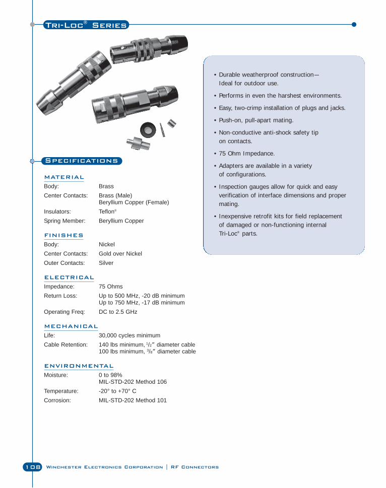
Specifications
MATERIAL
Body: BrassCenter Contacts: Brass (Male)
Beryllium Copper (Female)Insulators: Teflon®
Spring Member: Beryllium Copper
FINISHES
Body: NickelCenter Contacts: Gold over NickelOuter Contacts: Silver
ELECTRICAL
Impedance: 75 OhmsReturn Loss: Up to 500 MHz, -20 dB minimum
Up to 750 MHz, -17 dB minimumOperating Freq: DC to 2.5 GHz
MECHANICAL
Life: 30,000 cycles minimumCable Retention: 140 lbs minimum, 1/2” diameter cable
100 lbs minimum, 3/8” diameter cable
ENVIRONMENTAL
Moisture: 0 to 98%MIL-STD-202 Method 106
Temperature: -20° to +70° CCorrosion: MIL-STD-202 Method 101
• Durable weatherproof construction—Ideal for outdoor use.
• Performs in even the harshest environments.
• Easy, two-crimp installation of plugs and jacks.
• Push-on, pull-apart mating.
• Non-conductive anti-shock safety tip on contacts.
• 75 Ohm Impedance.
• Adapters are available in a variety of configurations.
• Inspection gauges allow for quick and easyverification of interface dimensions and propermating.
• Inexpensive retrofit kits for field replacementof damaged or non-functioning internal Tri-Loc® parts.
Tri-Loc® Series
108 Winchester Electronics Corporation | RF Connectors
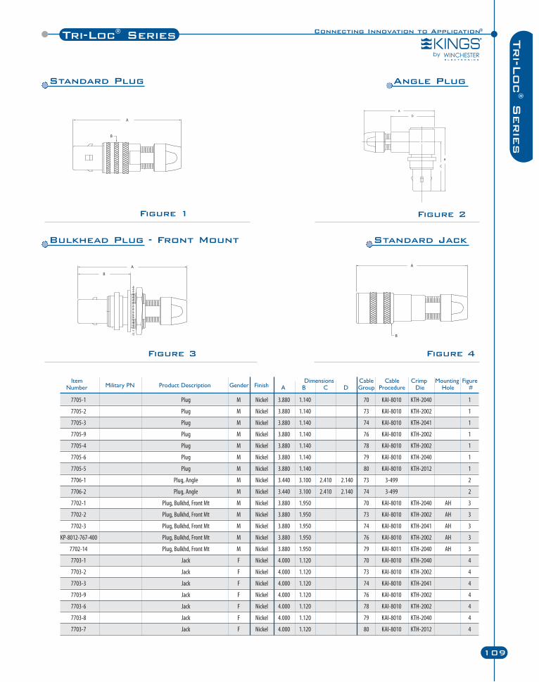
Connecting Innovation to Application®Tri-Loc® Series
109
Tri-L
oc
®S
erie
s
Figure 2
Figure 3
Figure 1
Figure 4
7705-1 Plug M Nickel 3.880 1.140 70 KAI-8010 KTH-2040 1
7705-2 Plug M Nickel 3.880 1.140 73 KAI-8010 KTH-2002 1
7705-3 Plug M Nickel 3.880 1.140 74 KAI-8010 KTH-2041 1
7705-9 Plug M Nickel 3.880 1.140 76 KAI-8010 KTH-2002 1
7705-4 Plug M Nickel 3.880 1.140 78 KAI-8010 KTH-2002 1
7705-6 Plug M Nickel 3.880 1.140 79 KAI-8010 KTH-2040 1
7705-5 Plug M Nickel 3.880 1.140 80 KAI-8010 KTH-2012 1
7706-1 Plug, Angle M Nickel 3.440 3.100 2.410 2.140 73 3-499 2
7706-2 Plug, Angle M Nickel 3.440 3.100 2.410 2.140 74 3-499 2
7702-1 Plug, Bulkhd, Front Mt M Nickel 3.880 1.950 70 KAI-8010 KTH-2040 AH 3
7702-2 Plug, Bulkhd, Front Mt M Nickel 3.880 1.950 73 KAI-8010 KTH-2002 AH 3
7702-3 Plug, Bulkhd, Front Mt M Nickel 3.880 1.950 74 KAI-8010 KTH-2041 AH 3
KP-8012-767-400 Plug, Bulkhd, Front Mt M Nickel 3.880 1.950 76 KAI-8010 KTH-2002 AH 3
7702-14 Plug, Bulkhd, Front Mt M Nickel 3.880 1.950 79 KAI-8011 KTH-2040 AH 3
7703-1 Jack F Nickel 4.000 1.120 70 KAI-8010 KTH-2040 4
7703-2 Jack F Nickel 4.000 1.120 73 KAI-8010 KTH-2002 4
7703-3 Jack F Nickel 4.000 1.120 74 KAI-8010 KTH-2041 4
7703-9 Jack F Nickel 4.000 1.120 76 KAI-8010 KTH-2002 4
7703-6 Jack F Nickel 4.000 1.120 78 KAI-8010 KTH-2002 4
7703-8 Jack F Nickel 4.000 1.120 79 KAI-8010 KTH-2040 4
7703-7 Jack F Nickel 4.000 1.120 80 KAI-8010 KTH-2012 4
Item Dimensions Cable Cable Crimp Mounting FigureNumber Military PN Product Description Gender Finish A B C D Group Procedure Die Hole #
Standard Plug Angle Plug
Bulkhead Plug - Front Mount Standard Jack
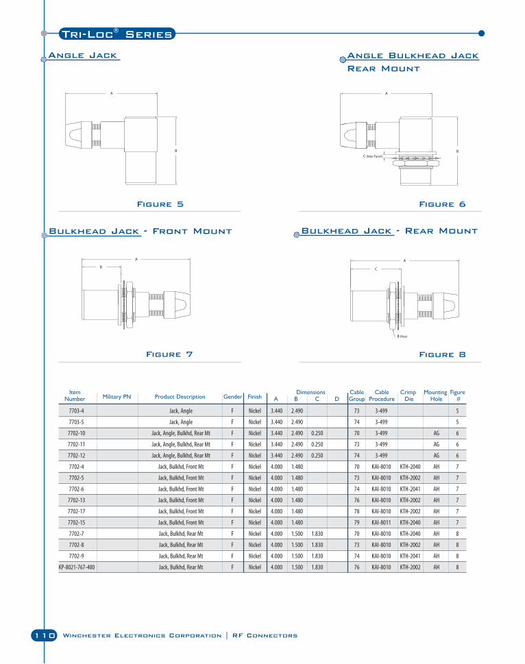
110 Winchester Electronics Corporation | RF Connectors
Tri-Loc® Series
Figure 5 Figure 6
Figure 8Figure 7
7703-4 Jack, Angle F Nickel 3.440 2.490 73 3-499 5
7703-5 Jack, Angle F Nickel 3.440 2.490 74 3-499 5
7702-10 Jack, Angle, Bulkhd, Rear Mt F Nickel 3.440 2.490 0.250 70 3-499 AG 6
7702-11 Jack, Angle, Bulkhd, Rear Mt F Nickel 3.440 2.490 0.250 73 3-499 AG 6
7702-12 Jack, Angle, Bulkhd, Rear Mt F Nickel 3.440 2.490 0.250 74 3-499 AG 6
7702-4 Jack, Bulkhd, Front Mt F Nickel 4.000 1.480 70 KAI-8010 KTH-2040 AH 7
7702-5 Jack, Bulkhd, Front Mt F Nickel 4.000 1.480 73 KAI-8010 KTH-2002 AH 7
7702-6 Jack, Bulkhd, Front Mt F Nickel 4.000 1.480 74 KAI-8010 KTH-2041 AH 7
7702-13 Jack, Bulkhd, Front Mt F Nickel 4.000 1.480 76 KAI-8010 KTH-2002 AH 7
7702-17 Jack, Bulkhd, Front Mt F Nickel 4.000 1.480 78 KAI-8010 KTH-2002 AH 7
7702-15 Jack, Bulkhd, Front Mt F Nickel 4.000 1.480 79 KAI-8011 KTH-2040 AH 7
7702-7 Jack, Bulkhd, Rear Mt F Nickel 4.000 1.500 1.830 70 KAI-8010 KTH-2040 AH 8
7702-8 Jack, Bulkhd, Rear Mt F Nickel 4.000 1.500 1.830 73 KAI-8010 KTH-2002 AH 8
7702-9 Jack, Bulkhd, Rear Mt F Nickel 4.000 1.500 1.830 74 KAI-8010 KTH-2041 AH 8
KP-8021-767-400 Jack, Bulkhd, Rear Mt F Nickel 4.000 1.500 1.830 76 KAI-8010 KTH-2002 AH 8
Item Dimensions Cable Cable Crimp Mounting FigureNumber Military PN Product Description Gender Finish A B C D Group Procedure Die Hole #
Angle Jack Angle Bulkhead Jack Rear Mount
Bulkhead Jack - Front Mount Bulkhead Jack - Rear Mount
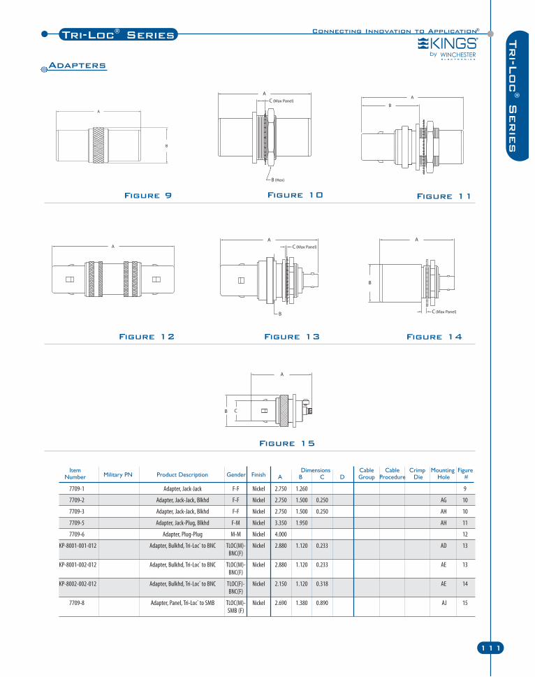
Connecting Innovation to Application®Tri-Loc® Series
111
Tri-L
oc
®S
erie
s
Figure 9 Figure 10
Figure 12 Figure 13
Figure 11
Figure 15
Figure 14
Item Dimensions Cable Cable Crimp Mounting FigureNumber Military PN Product Description Gender Finish A B C D Group Procedure Die Hole #
7709-1 Adapter, Jack-Jack F-F Nickel 2.750 1.260 9
7709-2 Adapter, Jack-Jack, Blkhd F-F Nickel 2.750 1.500 0.250 AG 10
7709-3 Adapter, Jack-Jack, Blkhd F-F Nickel 2.750 1.500 0.250 AH 10
7709-5 Adapter, Jack-Plug, Blkhd F-M Nickel 3.350 1.950 AH 11
7709-6 Adapter, Plug-Plug M-M Nickel 4.000 12
KP-8001-001-012 Adapter, Bulkhd, Tri-Loc® to BNC TLOC(M)- Nickel 2.880 1.120 0.233 AD 13BNC(F)
KP-8001-002-012 Adapter, Bulkhd, Tri-Loc® to BNC TLOC(M)- Nickel 2.880 1.120 0.233 AE 13BNC(F)
KP-8002-002-012 Adapter, Bulkhd, Tri-Loc® to BNC TLOC(F)- Nickel 2.150 1.120 0.318 AE 14BNC(F)
7709-8 Adapter, Panel, Tri-Loc® to SMB TLOC(M)- Nickel 2.690 1.380 0.890 AJ 15SMB (F)
Adapters
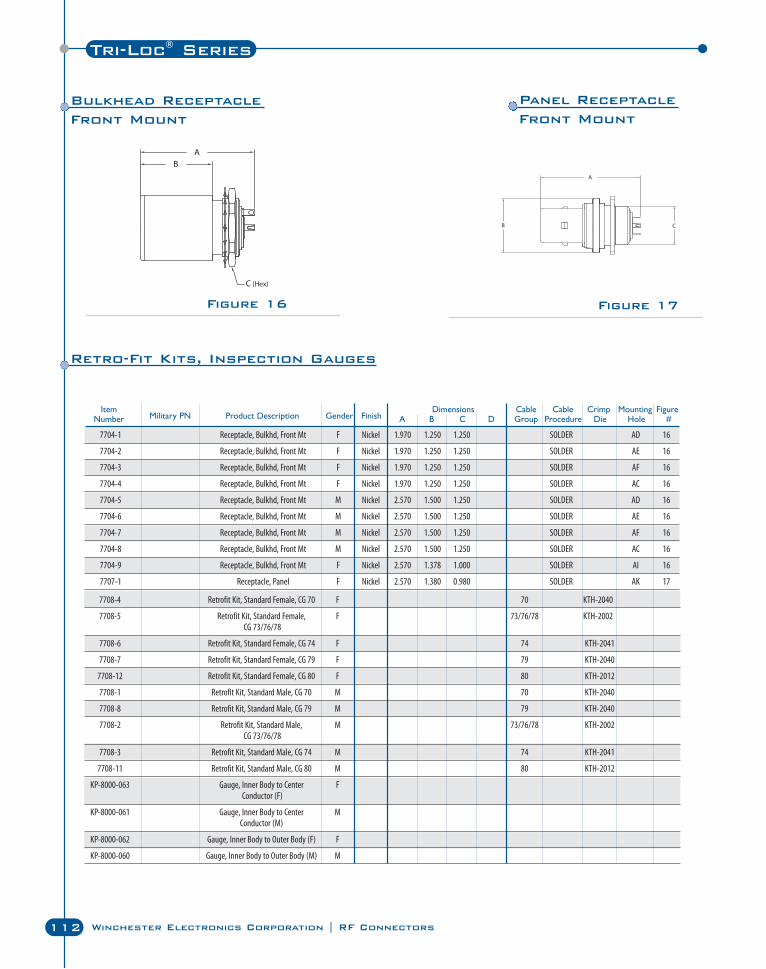
Tri-Loc® Series
112 Winchester Electronics Corporation | RF Connectors
Figure 16 Figure 17
Item Dimensions Cable Cable Crimp Mounting FigureNumber Military PN Product Description Gender Finish A B C D Group Procedure Die Hole #
7708-4 Retrofit Kit, Standard Female, CG 70 F 70 KTH-2040
7708-5 Retrofit Kit, Standard Female, F 73/76/78 KTH-2002CG 73/76/78
7708-6 Retrofit Kit, Standard Female, CG 74 F 74 KTH-2041
7708-7 Retrofit Kit, Standard Female, CG 79 F 79 KTH-2040
7708-12 Retrofit Kit, Standard Female, CG 80 F 80 KTH-2012
7708-1 Retrofit Kit, Standard Male, CG 70 M 70 KTH-2040
7708-8 Retrofit Kit, Standard Male, CG 79 M 79 KTH-2040
7708-2 Retrofit Kit, Standard Male, M 73/76/78 KTH-2002CG 73/76/78
7708-3 Retrofit Kit, Standard Male, CG 74 M 74 KTH-2041
7708-11 Retrofit Kit, Standard Male, CG 80 M 80 KTH-2012
KP-8000-063 Gauge, Inner Body to Center FConductor (F)
KP-8000-061 Gauge, Inner Body to Center MConductor (M)
KP-8000-062 Gauge, Inner Body to Outer Body (F) F
KP-8000-060 Gauge, Inner Body to Outer Body (M) M
7704-1 Receptacle, Bulkhd, Front Mt F Nickel 1.970 1.250 1.250 SOLDER AD 16
7704-2 Receptacle, Bulkhd, Front Mt F Nickel 1.970 1.250 1.250 SOLDER AE 16
7704-3 Receptacle, Bulkhd, Front Mt F Nickel 1.970 1.250 1.250 SOLDER AF 16
7704-4 Receptacle, Bulkhd, Front Mt F Nickel 1.970 1.250 1.250 SOLDER AC 16
7704-5 Receptacle, Bulkhd, Front Mt M Nickel 2.570 1.500 1.250 SOLDER AD 16
7704-6 Receptacle, Bulkhd, Front Mt M Nickel 2.570 1.500 1.250 SOLDER AE 16
7704-7 Receptacle, Bulkhd, Front Mt M Nickel 2.570 1.500 1.250 SOLDER AF 16
7704-8 Receptacle, Bulkhd, Front Mt M Nickel 2.570 1.500 1.250 SOLDER AC 16
7704-9 Receptacle, Bulkhd, Front Mt F Nickel 2.570 1.378 1.000 SOLDER AI 16
7707-1 Receptacle, Panel F Nickel 2.570 1.380 0.980 SOLDER AK 17
Bulkhead ReceptacleFront Mount
Panel ReceptacleFront Mount
Retro-Fit Kits, Inspection Gauges
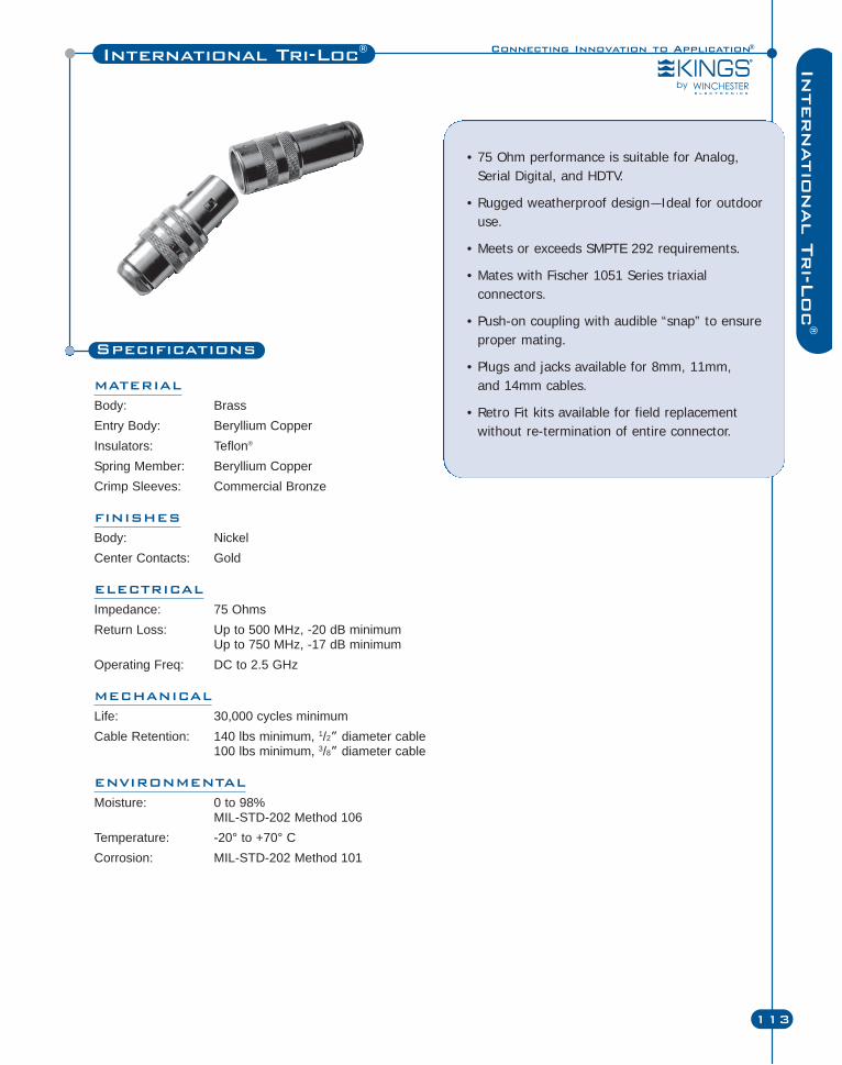
Connecting Innovation to Application®
C Series
113
Internatio
nal T
ri-L
oc
®
International Tri-Loc®
Specifications
MATERIAL
Body: BrassEntry Body: Beryllium CopperInsulators: Teflon®
Spring Member: Beryllium CopperCrimp Sleeves: Commercial Bronze
FINISHES
Body: NickelCenter Contacts: Gold
ELECTRICAL
Impedance: 75 OhmsReturn Loss: Up to 500 MHz, -20 dB minimum
Up to 750 MHz, -17 dB minimumOperating Freq: DC to 2.5 GHz
MECHANICAL
Life: 30,000 cycles minimumCable Retention: 140 lbs minimum, 1/2” diameter cable
100 lbs minimum, 3/8” diameter cable
ENVIRONMENTAL
Moisture: 0 to 98%MIL-STD-202 Method 106
Temperature: -20° to +70° CCorrosion: MIL-STD-202 Method 101
• 75 Ohm performance is suitable for Analog,Serial Digital, and HDTV.
• Rugged weatherproof design—Ideal for outdooruse.
• Meets or exceeds SMPTE 292 requirements.
• Mates with Fischer 1051 Series triaxialconnectors.
• Push-on coupling with audible “snap” to ensureproper mating.
• Plugs and jacks available for 8mm, 11mm, and 14mm cables.
• Retro Fit kits available for field replacementwithout re-termination of entire connector.
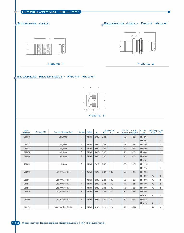
International Tri-Loc®
114 Winchester Electronics Corporation | RF Connectors
Figure 2Figure 1
Figure 3
Bulkhead Receptacle - Front Mount
Standard Jack Bulkhead Jack - Front Mount
780370 Jack, Crimp F Nickel 2.690 0.905 70 3-651 KTH-2040
KTH-2043 1
780373 Jack, Crimp F Nickel 2.690 0.905 73 3-651 KTH-8001 1
780374 Jack, Crimp F Nickel 2.690 0.905 74 3-651 KTH-8002 1
780376 Jack, Crimp F Nickel 2.690 0.905 76 3-651 KTH-8001 1
780380 Jack, Crimp F Nickel 2.690 0.905 80 3-651 KTH-2004
KTH-2012 1
780390 Jack, Crimp F Nickel 2.690 0.905 90 3-651 KTH-2267
KTH-2260 1
780270 Jack, Crimp, Bulkhd F Nickel 2.690 0.905 1.187 70 3-651 KTH-2040
KTH-2043 AL 2
780273 Jack, Crimp, Bulkhd F Nickel 2.690 0.905 1.187 73 3-651 KTH-8001 AL 2
780274 Jack, Crimp, Bulkhd F Nickel 2.690 0.905 1.187 74 3-651 KTH-8002 AL 2
780276 Jack, Crimp, Bulkhd F Nickel 2.690 0.905 1.187 76 3-651 KTH-8001 AL 2
780280 Jack, Crimp, Bulkhd F Nickel 2.690 0.905 1.187 80 3-651 KTH-2004
KTH-2012 AL 2
780290 Jack, Crimp, Bulkhd F Nickel 2.690 0.905 1.187 90 3-651 KTH-2267
KTH-2260 AL 2
781273 Receptacle, Plug, Bulkhd M Nickel 1.580 1.416 1.250 73 3-794 AM 3
Item Dimensions Cable Cable Crimp Mounting FigureNumber Military PN Product Description Gender Finish A B C D Group Procedure Die Hole #
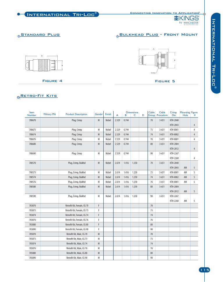
Connecting Innovation to Application®International Tri-Loc®
115
Internatio
nal T
ri-L
oc
®
Figure 5Figure 4
Standard Plug Bulkhead Plug - Front Mount
Retro-Fit Kits
Item Dimensions Cable Cable Crimp Mounting FigureNumber Military PN Product Description Gender Finish A B C D Group Procedure Die Hole #
780670 Plug, Crimp M Nickel 2.529 0.744 70 3-651 KTH-2040
KTH-2043 4
780673 Plug, Crimp M Nickel 2.529 0.744 73 3-651 KTH-8001 4
780674 Plug, Crimp M Nickel 2.529 0.744 74 3-651 KTH-8002 4
780676 Plug, Crimp M Nickel 2.529 0.744 76 3-651 KTH-8001 4
780680 Plug, Crimp M Nickel 2.529 0.744 80 3-651 KTH-2004
KTH-2012 4
780690 Plug, Crimp M Nickel 2.529 0.744 90 3-651 KTH-2267
KTH-2260 4
780570 Plug, Crimp, Bulkhd M Nickel 2.614 1.416 1.250 70 3-651 KTH-2040
KTH-2043 AM 5
780573 Plug, Crimp, Bulkhd M Nickel 2.614 1.416 1.250 73 3-651 KTH-8001 AM 5
780574 Plug, Crimp, Bulkhd M Nickel 2.614 1.416 1.250 74 3-651 KTH-8002 AM 5
780576 Plug, Crimp, Bulkhd M Nickel 2.614 1.416 1.250 76 3-651 KTH-8001 AM 5
780580 Plug, Crimp, Bulkhd M Nickel 2.614 1.416 1.250 80 3-651 KTH-2004
KTH-2012 AM 5
780590 Plug, Crimp, Bulkhd M Nickel 2.614 1.416 1.250 90 3-651 KTH-2267
KTH-2260 AM 5
783870 Retrofit Kit, Female, CG 70 F 70
783873 Retrofit Kit, Female, CG 73 F 73
783874 Retrofit Kit, Female, CG 74 F 74
783876 Retrofit Kit, Female, CG 76 F 76
783880 Retrofit Kit, Female, CG 80 F 80
783890 Retrofit Kit, Female, CG 90 F 90
785870 Retrofit Kit, Male, CG 70 M 70
785873 Retrofit Kit, Male, CG 73 M 73
785874 Retrofit Kit, Male, CG 74 M 74
785876 Retrofit Kit, Male, CG 76 M 76
785880 Retrofit Kit, Male, CG 80 M 80
785890 Retrofit Kit, Male, CG 90 M 90
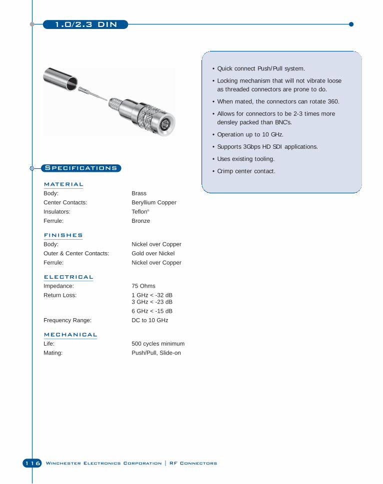
1.0/2.3 DIN
116 Winchester Electronics Corporation | RF Connectors
Specifications
MATERIAL
Body: BrassCenter Contacts: Beryllium CopperInsulators: Teflon®
Ferrule: Bronze
FINISHES
Body: Nickel over CopperOuter & Center Contacts: Gold over NickelFerrule: Nickel over Copper
ELECTRICAL
Impedance: 75 OhmsReturn Loss: 1 GHz < -32 dB
3 GHz < -23 dB6 GHz < -15 dB
Frequency Range: DC to 10 GHz
MECHANICAL
Life: 500 cycles minimumMating: Push/Pull, Slide-on
• Quick connect Push/Pull system.
• Locking mechanism that will not vibrate looseas threaded connectors are prone to do.
• When mated, the connectors can rotate 360.
• Allows for connectors to be 2-3 times moredensley packed than BNC’s.
• Operation up to 10 GHz.
• Supports 3Gbps HD SDI applications.
• Uses existing tooling.
• Crimp center contact.
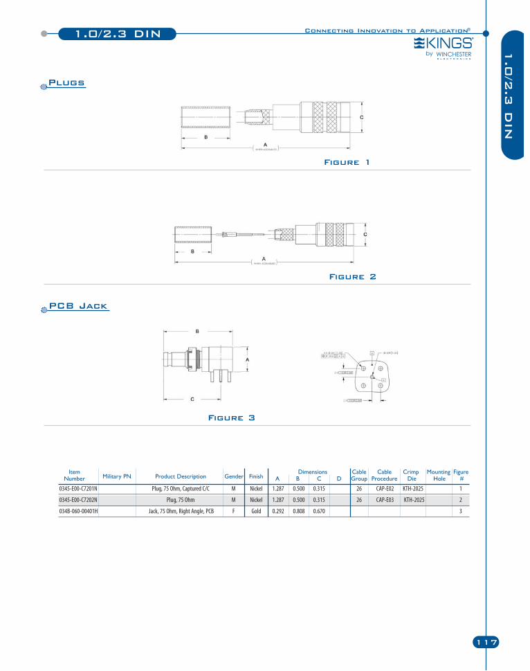
1.0/2.3 DIN
117
1.0
/2.3
DIN
Connecting Innovation to Application®
Item Dimensions Cable Cable Crimp Mounting FigureNumber Military PN Product Description Gender Finish A B C D Group Procedure Die Hole #
0345-E00-C7201N Plug, 75 Ohm, Captured C/C M Nickel 1.287 0.500 0.315 26 CAP-E02 KTH-2025 1
0345-E00-C7202N Plug, 75 Ohm M Nickel 1.287 0.500 0.315 26 CAP-E03 KTH-2025 2
034B-060-00401H Jack, 75 Ohm, Right Angle, PCB F Gold 0.292 0.808 0.670 3
Figure 1
Plugs
Figure 2
Figure 3
PCB Jack
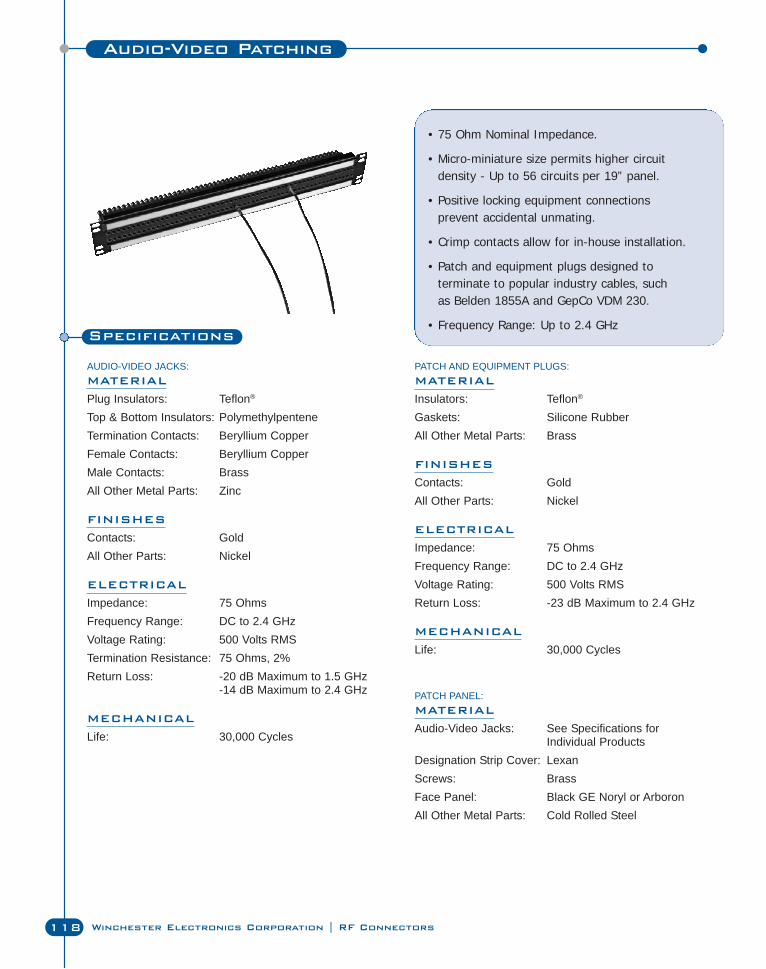
Audio-Video Patching
118 Winchester Electronics Corporation | RF Connectors
Specifications
AUDIO-VIDEO JACKS:MATERIAL
Plug Insulators: Teflon®
Top & Bottom Insulators: PolymethylpenteneTermination Contacts: Beryllium CopperFemale Contacts: Beryllium CopperMale Contacts: BrassAll Other Metal Parts: Zinc
FINISHES
Contacts: GoldAll Other Parts: Nickel
ELECTRICAL
Impedance: 75 OhmsFrequency Range: DC to 2.4 GHzVoltage Rating: 500 Volts RMSTermination Resistance: 75 Ohms, 2%Return Loss: -20 dB Maximum to 1.5 GHz
-14 dB Maximum to 2.4 GHz
MECHANICAL
Life: 30,000 Cycles
• 75 Ohm Nominal Impedance.
• Micro-miniature size permits higher circuit density - Up to 56 circuits per 19” panel.
• Positive locking equipment connections prevent accidental unmating.
• Crimp contacts allow for in-house installation.
• Patch and equipment plugs designed to terminate to popular industry cables, such as Belden 1855A and GepCo VDM 230.
• Frequency Range: Up to 2.4 GHz
PATCH AND EQUIPMENT PLUGS:MATERIAL
Insulators: Teflon®
Gaskets: Silicone RubberAll Other Metal Parts: Brass
FINISHES
Contacts: GoldAll Other Parts: Nickel
ELECTRICAL
Impedance: 75 OhmsFrequency Range: DC to 2.4 GHzVoltage Rating: 500 Volts RMSReturn Loss: -23 dB Maximum to 2.4 GHz
MECHANICAL
Life: 30,000 Cycles
PATCH PANEL:MATERIAL
Audio-Video Jacks: See Specifications for Individual Products
Designation Strip Cover: LexanScrews: BrassFace Panel: Black GE Noryl or ArboronAll Other Metal Parts: Cold Rolled Steel
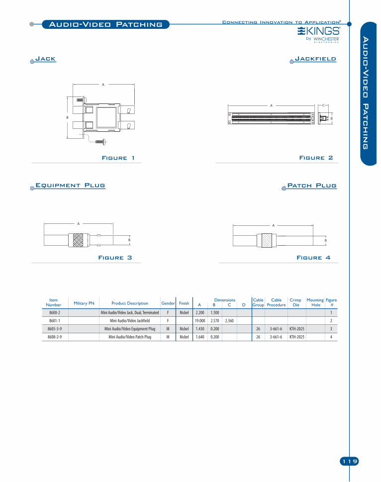
Connecting Innovation to Application®Audio-Video Patching
119
Audio
-Vid
eo P
atchin
g
Figure 2Figure 1
Figure 4Figure 3
Item Dimensions Cable Cable Crimp Mounting FigureNumber Military PN Product Description Gender Finish A B C D Group Procedure Die Hole #
8600-2 Mini Audio/Video Jack, Dual, Terminated F Nickel 2.200 1.500 1
8601-1 Mini Audio/Video Jackfield F 19.000 2.570 2.360 2
8605-3-9 Mini Audio/Video Equipment Plug M Nickel 1.430 0.200 26 3-661-6 KTH-2025 3
8608-2-9 Mini Audio/Video Patch Plug M Nickel 1.640 0.200 26 3-661-6 KTH-2025 4
Jack Jackfield
Equipment Plug Patch Plug
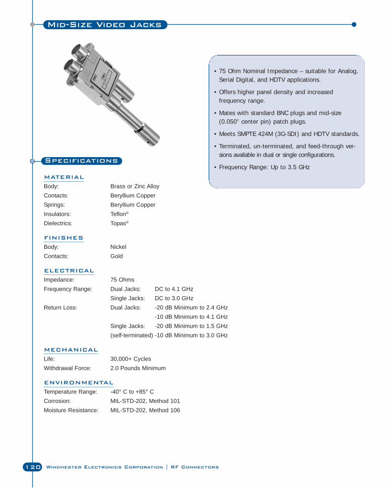
Mid-Size Video Jacks
120 Winchester Electronics Corporation | RF Connectors
Specifications
MATERIAL
Body: Brass or Zinc AlloyContacts: Beryllium CopperSprings: Beryllium CopperInsulators: Teflon®
Dielectrics: Topas®
FINISHES
Body: NickelContacts: Gold
ELECTRICAL
Impedance: 75 OhmsFrequency Range: Dual Jacks: DC to 4.1 GHz
Single Jacks: DC to 3.0 GHzReturn Loss: Dual Jacks: -20 dB Minimum to 2.4 GHz
-10 dB Minimum to 4.1 GHzSingle Jacks: -20 dB Minimum to 1.5 GHz(self-terminated) -10 dB Minimum to 3.0 GHz
MECHANICAL
Life: 30,000+ CyclesWithdrawal Force: 2.0 Pounds Minimum
ENVIRONMENTAL
Temperature Range: -40° C to +85° CCorrosion: MIL-STD-202, Method 101Moisture Resistance: MIL-STD-202, Method 106
• 75 Ohm Nominal Impedance – suitable for Analog,Serial Digital, and HDTV applications.
• Offers higher panel density and increased frequency range.
• Mates with standard BNC plugs and mid-size(0.050” center pin) patch plugs.
• Meets SMPTE 424M (3G-SDI) and HDTV standards.
• Terminated, un-terminated, and feed-through ver-sions available in dual or single configurations.
• Frequency Range: Up to 3.5 GHz
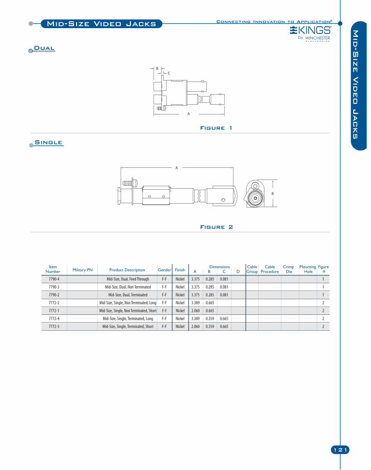
Connecting Innovation to Application®Mid-Size Video Jacks
121
Mid
-Siz
e V
ideo J
acksFigure 1
Item Dimensions Cable Cable Crimp Mounting FigureNumber Military PN Product Description Gender Finish A B C D Group Procedure Die Hole #
7790-4 Mid-Size, Dual, Feed Through F-F Nickel 3.375 0.285 0.081 1
7790-3 Mid-Size, Dual, Non Terminated F-F Nickel 3.375 0.285 0.081 1
7790-2 Mid-Size, Dual, Terminated F-F Nickel 3.375 0.285 0.081 1
7772-2 Mid-Size, Single, Non Terminated, Long F-F Nickel 3.389 0.665 2
7772-1 Mid-Size, Single, Non Terminated, Short F-F Nickel 2.060 0.665 2
7772-4 Mid-Size, Single, Terminated, Long F-F Nickel 3.389 0.359 0.665 2
7772-3 Mid-Size, Single, Terminated, Short F-F Nickel 2.060 0.359 0.665 2
Figure 2
Dual
Single
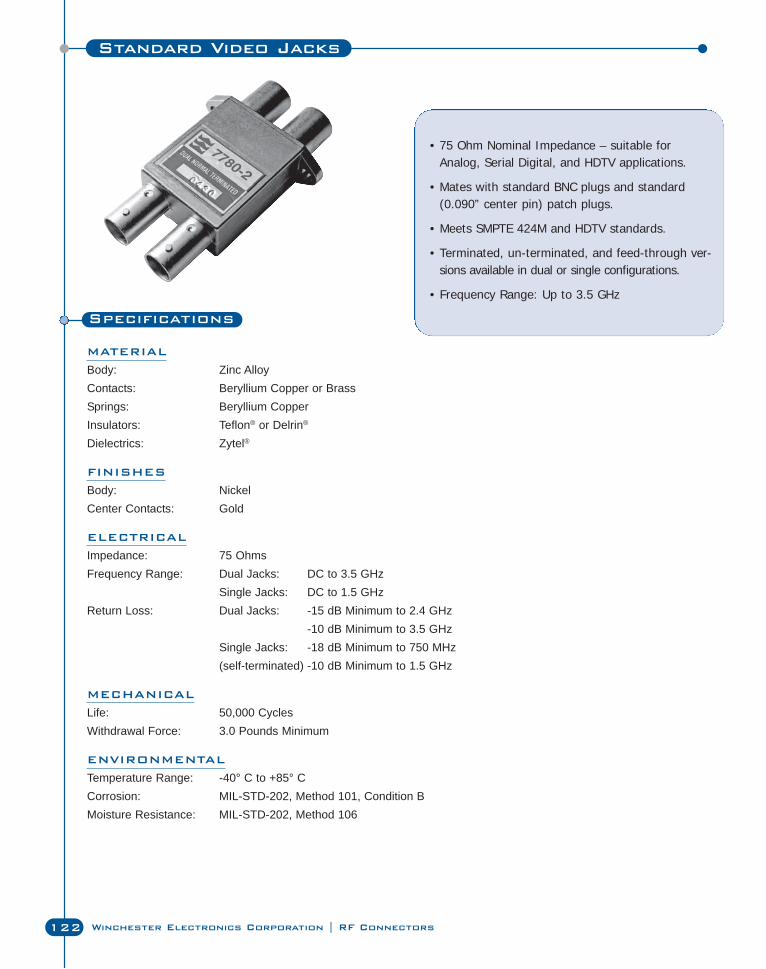
122 Winchester Electronics Corporation | RF Connectors
Standard Video Jacks
Specifications
MATERIAL
Body: Zinc AlloyContacts: Beryllium Copper or BrassSprings: Beryllium CopperInsulators: Teflon® or Delrin®
Dielectrics: Zytel®
FINISHES
Body: NickelCenter Contacts: Gold
ELECTRICAL
Impedance: 75 OhmsFrequency Range: Dual Jacks: DC to 3.5 GHz
Single Jacks: DC to 1.5 GHzReturn Loss: Dual Jacks: -15 dB Minimum to 2.4 GHz
-10 dB Minimum to 3.5 GHzSingle Jacks: -18 dB Minimum to 750 MHz(self-terminated) -10 dB Minimum to 1.5 GHz
MECHANICAL
Life: 50,000 CyclesWithdrawal Force: 3.0 Pounds Minimum
ENVIRONMENTAL
Temperature Range: -40° C to +85° CCorrosion: MIL-STD-202, Method 101, Condition BMoisture Resistance: MIL-STD-202, Method 106
• 75 Ohm Nominal Impedance – suitable forAnalog, Serial Digital, and HDTV applications.
• Mates with standard BNC plugs and standard(0.090” center pin) patch plugs.
• Meets SMPTE 424M and HDTV standards.
• Terminated, un-terminated, and feed-through ver-sions available in dual or single configurations.
• Frequency Range: Up to 3.5 GHz
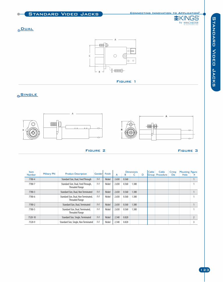
Sta
ndard V
ideo J
acks
Connecting Innovation to Application®
123
Figure 2
Figure 1
Standard Video Jacks
Item Dimensions Cable Cable Crimp Mounting FigureNumber Military PN Product Description Gender Finish A B C D Group Procedure Die Hole #
7780-4 Standard Size, Dual, Feed Through F-F Nickel 2.650 0.560 1
7780-7 Standard Size, Dual, Feed Through, F-F Nickel 2.650 0.560 1.380 1Threaded Flange
7780-3 Standard Size, Dual, Non Terminated F-F Nickel 2.650 0.560 1.380 1
7780-6 Standard Size, Dual, Non Terminated, F-F Nickel 2.650 0.560 1.380 1Threaded Flange
7780-2 Standard Size, Dual, Terminated F-F Nickel 2.650 0.560 1.380 1
7780-5 Standard Size, Dual, Terminated, F-F Nickel 2.650 0.560 1.380 1Threaded Flange
7520-10 Standard Size, Single, Terminated F-F Nickel 2.540 0.820 2
7520-9 Standard Size, Single, Non Terminated F-F Nickel 2.540 0.820 3
Figure 3
Dual
Single
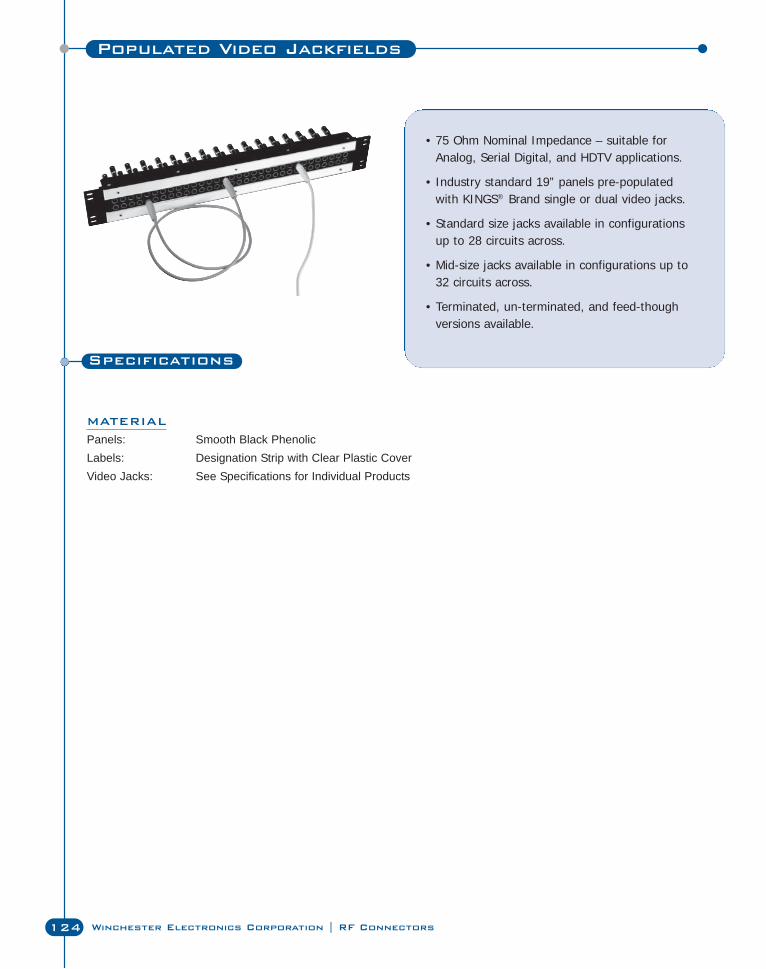
C Series
124 Winchester Electronics Corporation | RF Connectors
Populated Video Jackfields
Specifications
MATERIAL
Panels: Smooth Black PhenolicLabels: Designation Strip with Clear Plastic CoverVideo Jacks: See Specifications for Individual Products
• 75 Ohm Nominal Impedance – suitable forAnalog, Serial Digital, and HDTV applications.
• Industry standard 19” panels pre-populatedwith KINGS® Brand single or dual video jacks.
• Standard size jacks available in configurationsup to 28 circuits across.
• Mid-size jacks available in configurations up to32 circuits across.
• Terminated, un-terminated, and feed-thoughversions available.
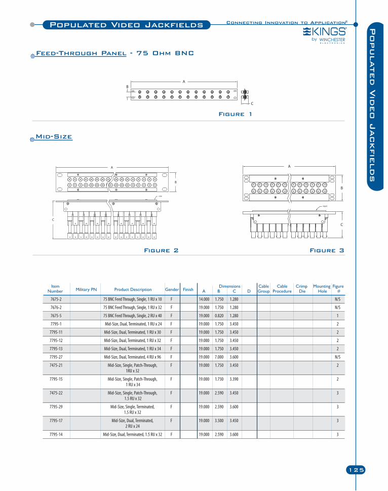
7675-2 75 BNC Feed Through, Single, 1 RU x 10 F 14.000 1.750 1.280 N/S
7676-2 75 BNC Feed Through, Single, 1 RU x 32 F 19.000 1.750 1.280 N/S
7675-5 75 BNC Feed Through, Single, 2 RU x 40 F 19.000 0.820 1.280 1
7795-1 Mid-Size, Dual, Terminated, 1 RU x 24 F 19.000 1.750 3.450 2
7795-11 Mid-Size, Dual, Terminated, 1 RU x 30 F 19.000 1.750 3.450 2
7795-12 Mid-Size, Dual, Terminated, 1 RU x 32 F 19.000 1.750 3.450 2
7795-13 Mid-Size, Dual, Terminated, 1 RU x 34 F 19.000 1.750 3.450 2
7795-27 Mid-Size, Dual, Terminated, 4 RU x 96 F 19.000 7.000 3.600 N/S
7475-21 Mid-Size, Single, Patch-Through, F 19.000 1.750 3.450 21RU x 32
7795-15 Mid-Size, Single, Patch-Through, F 19.000 1.730 3.390 21 RU x 34
7475-22 Mid-Size, Single, Patch-Through, F 19.000 2.590 3.450 31.5 RU x 32
7795-29 Mid-Size, Single, Terminated, F 19.000 2.590 3.600 31.5 RU x 32
7795-17 Mid-Size, Dual, Terminated, F 19.000 3.500 3.450 32 RU x 24
7795-14 Mid-Size, Dual, Terminated, 1.5 RU x 32 F 19.000 2.590 3.600 3
Connecting Innovation to Application®Populated Video Jackfields
125
Populated V
ideo J
ackfie
lds
Figure 2 Figure 3
Figure 1
Item Dimensions Cable Cable Crimp Mounting FigureNumber Military PN Product Description Gender Finish A B C D Group Procedure Die Hole #
Feed-Through Panel - 75 Ohm BNC
Mid-Size
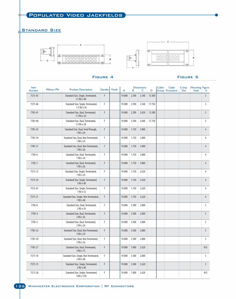
C Series
126 Winchester Electronics Corporation | RF Connectors
Populated Video Jackfields
Figure 4 Figure 5
Item Dimensions Cable Cable Crimp Mounting FigureNumber Military PN Product Description Gender Finish A B C D Group Procedure Die Hole #
7575-45 Standard Size, Single, Terminated, F 19.000 2.590 2.540 15.500 31.5 RU x 48
7575-46 Standard Size, Single, Terminated, F 19.000 2.590 2.540 17.750 31.5 RU x 56
7785-41 Standard Size, Dual, Terminated, F 19.000 2.590 2.650 15.500 31.5 RU x 24
7785-40 Standard Size, Dual, Terminated, F 19.000 2.590 2.640 17.750 31.5 RU x 28
7785-42 Standard Size, Dual, Feed Through, F 19.000 1.750 2.800 41 RU x 24
7785-29 Standard Size, Dual, Non Terminated, F 19.000 1.750 2.800 41 RU x 24
7785-31 Standard Size, Dual, Non Terminated, F 19.000 1.750 2.800 41 RU x 26
7785-6 Standard Size, Dual, Terminated, F 19.000 1.750 2.800 41 RU x 24
7785-7 Standard Size, Dual, Terminated, F 19.000 1.750 2.800 41 RU x 26
7575-13 Standard Size, Single, Terminated, F 19.000 1.750 2.620 41 RU x 24
7575-24 Standard Size, Single, Terminated, F 19.000 1.750 2.620 41 RU x 48
7575-47 Standard Size, Single, Terminated, F 19.000 1.750 2.620 41 RU x 52
7575-21 Standard Size, Single, Non Terminated, F 19.000 1.750 2.620 41 RU x 48
7785-8 Standard Size, Dual, Terminated, F 19.000 3.500 2.800 52 RU x 24
7785-4 Standard Size, Dual, Terminated, F 19.000 3.500 2.800 52 RU x 26
7785-5 Standard Size, Dual, Terminated, F 19.000 3.500 2.800 52 RU x 26
7785-32 Standard Size, Dual, Non Terminated, F 19.000 3.500 2.800 52 RU x 24
7785-30 Standard Size, Dual, Non Terminated, F 19.000 3.500 2.800 52 RU x 26
7785-27 Standard Size, Dual, Terminated, F 19.000 7.000 2.620 N/S4 RU x 75
7575-18 Standard Size, Single, Non Terminated, F 19.000 3.500 2.800 52 RU x 48
7575-15 Standard Size, Single, Terminated, F 19.000 3.500 2.620 52 RU x 48
7575-26 Standard Size, Single, Terminated, F 19.000 7.000 2.620 N/S4 RU x 150
Standard Size

KTH-5000
Hand Crimping Tool
• Economical and user-friendly alternative to other industrial crimping tools.
• Lightweight, ergonomic tool allows for one-handed operation.
• Ultra-smooth ratchet design with rubber grip handles.
• Available dies developed specifically for precisecrimping of KINGS® connectors.
KTS-8-1 and KTS-8-2
Manual Stripping Tools
• Hand-held tool is lightweight and compact -ideal for field use.
• Blade cassettes and memory blocks interchangequickly and easily.
• Cam adjustment ensures precise hold on cablewithout distorting the jacket.
• KTS-8-1 is designed specifically for the Belden 179DT Cable.
• KTS-8-2 is adjustable for use in most two- andthree-piece BNC applications.
KTH-1000
Hand Crimping Tool
• Field-tested and approved - an industry favorite.
• Ratchet-type tool does not release until crimp is complete.
• Robust and reliable - frame made of heavy-duty,lightweight aluminum.
• Interchangeable dies available to fit a variety ofconnector and cable types.
Strain Relief Boots
• Protects from wear, fatigue, and weather.
• Designed to fit a variety of industry-leadingbroadcast cables.
• Available in 10 popular colors.
Connecting Innovation to Application®
127
Tools &
Accessorie
sTools & Accessories
KTM-5000
Pneumatic Crimping Machine
• Portable, bench-mounted with no permanent lines attached.
• Designed for use with KINGS® KTH-1000 and KTH-2000 die sets.
• Ideal for long or short production runs.
• Convenient foot control frees operator hands for crimping.
• Quick and easy changing from one die to another.
• Pneumatic interlock feature guarantees constant crimping.
• Designed with OSHA safety requirements in mind.
• Low maintenance.
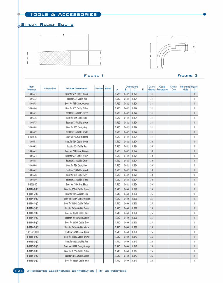
Tools & Accessories
128 Winchester Electronics Corporation | RF Connectors
Strain Relief Boots
Item Dimensions Cable Cable Crimp Mounting FigureNumber Military PN Product Description Gender Finish A B C D Group Procedure Die Hole #
1-8065-1 Boot for 735 Cable, Brown 1.520 0.442 0.324 31 1
1-8065-2 Boot for 735 Cable, Red 1.520 0.442 0.324 31 1
1-8065-3 Boot for 735 Cable, Orange 1.520 0.442 0.324 31 1
1-8065-4 Boot for 735 Cable, Yellow 1.520 0.442 0.324 31 1
1-8065-5 Boot for 735 Cable, Green 1.520 0.442 0.324 31 1
1-8065-6 Boot for 735 Cable, Blue 1.520 0.442 0.324 31 1
1-8065-7 Boot for 735 Cable, Violet 1.520 0.442 0.324 31 1
1-8065-8 Boot for 735 Cable, Grey 1.520 0.442 0.324 31 1
1-8065-9 Boot for 735 Cable, White 1.520 0.442 0.324 31 1
1-8065-10 Boot for 735 Cable, Black 1.520 0.442 0.324 31 1
1-8066-1 Boot for 734 Cable, Brown 1.520 0.442 0.324 30 1
1-8066-2 Boot for 734 Cable, Red 1.520 0.442 0.324 30 1
1-8066-3 Boot for 734 Cable, Orange 1.520 0.442 0.324 30 1
1-8066-4 Boot for 734 Cable, Yellow 1.520 0.442 0.324 30 1
1-8066-5 Boot for 734 Cable, Green 1.520 0.442 0.324 30 1
1-8066-6 Boot for 734 Cable, Blue 1.520 0.442 0.324 30 1
1-8066-7 Boot for 734 Cable, Violet 1.520 0.442 0.324 30 1
1-8066-8 Boot for 734 Cable, Grey 1.520 0.442 0.324 30 1
1-8066-9 Boot for 734 Cable, White 1.520 0.442 0.324 30 1
1-8066-10 Boot for 734 Cable, Black 1.520 0.442 0.324 30 1
1-8114-1 QD Boot for 1694A Cable, Brown 1.540 0.460 0.390 25 1
1-8114-2 QD Boot for 1694A Cable, Red 1.540 0.460 0.390 25 1
1-8114-3 QD Boot for 1694A Cable, Orange 1.540 0.460 0.390 25 1
1-8114-4 QD Boot for 1694A Cable, Yellow 1.540 0.460 0.390 25 1
1-8114-5 QD Boot for 1694A Cable, Green 1.540 0.460 0.390 25 1
1-8114-6 QD Boot for 1694A Cable, Blue 1.540 0.460 0.390 25 1
1-8114-7 QD Boot for 1694A Cable, Violet 1.540 0.460 0.390 25 1
1-8114-8 QD Boot for 1694A Cable, Grey 1.540 0.460 0.390 25 1
1-8114-9 QD Boot for 1694A Cable, White 1.540 0.460 0.390 25 1
1-8114-10 QD Boot for 1694A Cable, Black 1.540 0.460 0.390 25 1
1-8115-1 QD Boot for 1855A Cable, Brown 1.540 0.460 0.347 26 1
1-8115-2 QD Boot for 1855A Cable, Red 1.540 0.460 0.347 26 1
1-8115-3 QD Boot for 1855A Cable, Orange 1.540 0.460 0.347 26 1
1-8115-4 QD Boot for 1855A Cable, Yellow 1.540 0.460 0.347 26 1
1-8115-5 QD Boot for 1855A Cable, Green 1.540 0.460 0.347 26 1
1-8115-6 QD Boot for 1855A Cable, Blue 1.540 0.460 0.347 26 1
Figure 2Figure 1
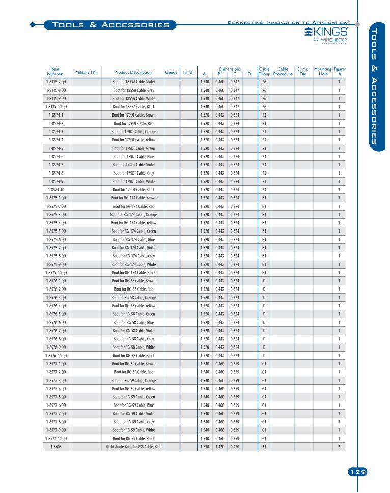
Connecting Innovation to Application®
129
Tools &
Accessorie
sTools & Accessories
Item Dimensions Cable Cable Crimp Mounting FigureNumber Military PN Product Description Gender Finish A B C D Group Procedure Die Hole #
1-8115-7 QD Boot for 1855A Cable, Violet 1.540 0.460 0.347 26 1
1-8115-8 QD Boot for 1855A Cable, Grey 1.540 0.460 0.347 26 1
1-8115-9 QD Boot for 1855A Cable, White 1.540 0.460 0.347 26 1
1-8115-10 QD Boot for 1855A Cable, Black 1.540 0.460 0.347 26 1
1-8574-1 Boot for 179DT Cable, Brown 1.520 0.442 0.324 23 1
1-8574-2 Boot for 179DT Cable, Red 1.520 0.442 0.324 23 1
1-8574-3 Boot for 179DT Cable, Orange 1.520 0.442 0.324 23 1
1-8574-4 Boot for 179DT Cable, Yellow 1.520 0.442 0.324 23 1
1-8574-5 Boot for 179DT Cable, Green 1.520 0.442 0.324 23 1
1-8574-6 Boot for 179DT Cable, Blue 1.520 0.442 0.324 23 1
1-8574-7 Boot for 179DT Cable, Violet 1.520 0.442 0.324 23 1
1-8574-8 Boot for 179DT Cable, Grey 1.520 0.442 0.324 23 1
1-8574-9 Boot for 179DT Cable, White 1.520 0.442 0.324 23 1
1-8574-10 Boot for 179DT Cable, Black 1.520 0.442 0.324 23 1
1-8575-1 QD Boot for RG-174 Cable, Brown 1.520 0.442 0.324 B1 1
1-8575-2 QD Boot for RG-174 Cable, Red 1.520 0.442 0.324 B1 1
1-8575-3 QD Boot for RG-174 Cable, Orange 1.520 0.442 0.324 B1 1
1-8575-4 QD Boot for RG-174 Cable, Yellow 1.520 0.442 0.324 B1 1
1-8575-5 QD Boot for RG-174 Cable, Green 1.520 0.442 0.324 B1 1
1-8575-6 QD Boot for RG-174 Cable, Blue 1.520 0.442 0.324 B1 1
1-8575-7 QD Boot for RG-174 Cable, Violet 1.520 0.442 0.324 B1 1
1-8575-8 QD Boot for RG-174 Cable, Grey 1.520 0.442 0.324 B1 1
1-8575-9 QD Boot for RG-174 Cable, White 1.520 0.442 0.324 B1 1
1-8575-10 QD Boot for RG-174 Cable, Black 1.520 0.442 0.324 B1 1
1-8576-1 QD Boot for RG-58 Cable, Brown 1.520 0.442 0.324 D 1
1-8576-2 QD Boot for RG-58 Cable, Red 1.520 0.442 0.324 D 1
1-8576-3 QD Boot for RG-58 Cable, Orange 1.520 0.442 0.324 D 1
1-8576-4 QD Boot for RG-58 Cable, Yellow 1.520 0.442 0.324 D 1
1-8576-5 QD Boot for RG-58 Cable, Green 1.520 0.442 0.324 D 1
1-8576-6 QD Boot for RG-58 Cable, Blue 1.520 0.442 0.324 D 1
1-8576-7 QD Boot for RG-58 Cable, Violet 1.520 0.442 0.324 D 1
1-8576-8 QD Boot for RG-58 Cable, Grey 1.520 0.442 0.324 D 1
1-8576-9 QD Boot for RG-58 Cable, White 1.520 0.442 0.324 D 1
1-8576-10 QD Boot for RG-58 Cable, Black 1.520 0.442 0.324 D 1
1-8577-1 QD Boot for RG-59 Cable, Brown 1.540 0.460 0.359 G1 1
1-8577-2 QD Boot for RG-59 Cable, Red 1.540 0.460 0.359 G1 1
1-8577-3 QD Boot for RG-59 Cable, Orange 1.540 0.460 0.359 G1 1
1-8577-4 QD Boot for RG-59 Cable, Yellow 1.540 0.460 0.359 G1 1
1-8577-5 QD Boot for RG-59 Cable, Green 1.540 0.460 0.359 G1 1
1-8577-6 QD Boot for RG-59 Cable, Blue 1.540 0.460 0.359 G1 1
1-8577-7 QD Boot for RG-59 Cable, Violet 1.540 0.460 0.359 G1 1
1-8577-8 QD Boot for RG-59 Cable, Grey 1.540 0.460 0.359 G1 1
1-8577-9 QD Boot for RG-59 Cable, White 1.540 0.460 0.359 G1 1
1-8577-10 QD Boot for RG-59 Cable, Black 1.540 0.460 0.359 G1 1
1-8603 Right Angle Boot for 735 Cable, Blue 1.710 1.420 0.470 31 2
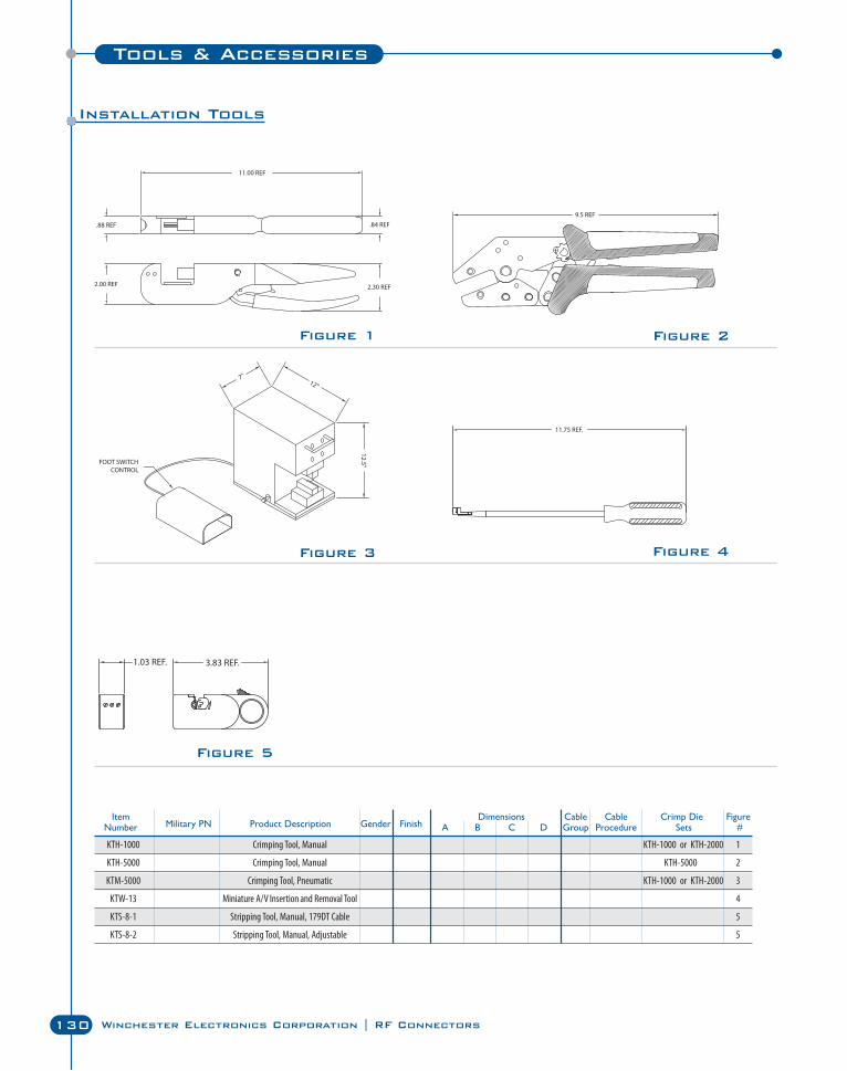
C Series
130 Winchester Electronics Corporation | RF Connectors
Figure 2
Figure 3
Figure 1
Figure 5
Figure 4
Tools & Accessories
Installation Tools
KTH-1000 Crimping Tool, Manual KTH-1000 or KTH-2000 1
KTH-5000 Crimping Tool, Manual KTH-5000 2
KTM-5000 Crimping Tool, Pneumatic KTH-1000 or KTH-2000 3
KTW-13 Miniature A/V Insertion and Removal Tool 4
KTS-8-1 Stripping Tool, Manual, 179DT Cable 5
KTS-8-2 Stripping Tool, Manual, Adjustable 5
Item Dimensions Cable Cable Crimp Die FigureNumber Military PN Product Description Gender Finish A B C D Group Procedure Sets #
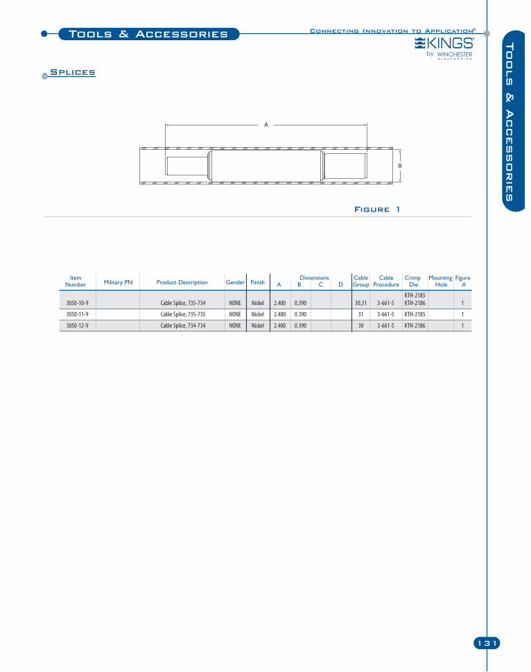
Figure 1
Connecting Innovation to Application®Tools & Accessories
131
Tools &
Accessorie
s
Item Dimensions Cable Cable Crimp Mounting FigureNumber Military PN Product Description Gender Finish A B C D Group Procedure Die Hole #
KTH-21853050-10-9 Cable Splice, 735-734 NONE Nickel 2.400 0.390 30,31 3-661-5 KTH-2186 1
3050-11-9 Cable Splice, 735-735 NONE Nickel 2.400 0.390 31 3-661-5 KTH-2185 1
3050-12-9 Cable Splice, 734-734 NONE Nickel 2.400 0.390 30 3-661-5 KTH-2186 1
Splices
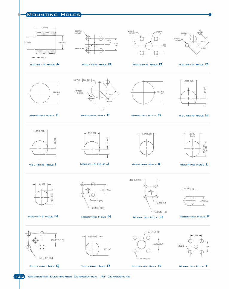
Mounting Holes
132 Winchester Electronics Corporation | RF Connectors
Mounting Hole A Mounting Hole B Mounting Hole C Mounting Hole D
Mounting Hole E Mounting Hole F Mounting Hole G Mounting Hole H
Mounting Hole I Mounting Hole J Mounting Hole K Mounting Hole L
Mounting Hole M Mounting Hole N Mounting Hole O Mounting Hole P
Mounting Hole Q Mounting Hole R Mounting Hole S Mounting Hole T
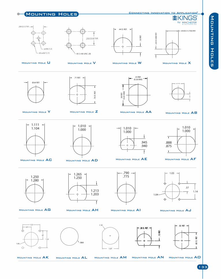
Connecting Innovation to Application®Mounting Holes
133
Mountin
g H
olesMounting Hole U Mounting Hole V Mounting Hole W Mounting Hole X
Mounting Hole Y Mounting Hole Z Mounting Hole AA Mounting Hole AB
Mounting Hole AC Mounting Hole AD Mounting Hole AE Mounting Hole AF
Mounting Hole AG Mounting Hole AH Mounting Hole AJMounting Hole AI
Mounting Hole AK Mounting Hole AL Mounting Hole AM Mounting Hole AN Mounting Hole AO
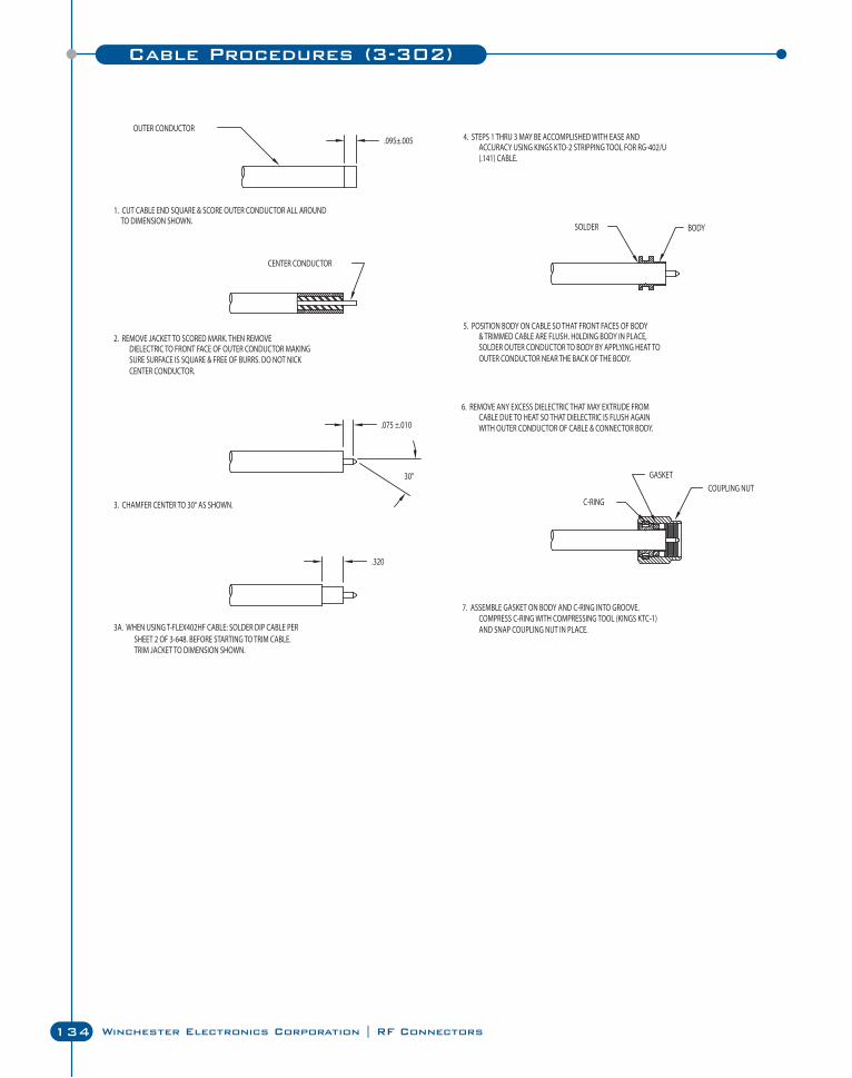
134 Winchester Electronics Corporation | RF Connectors
Cable Procedures (3-302)
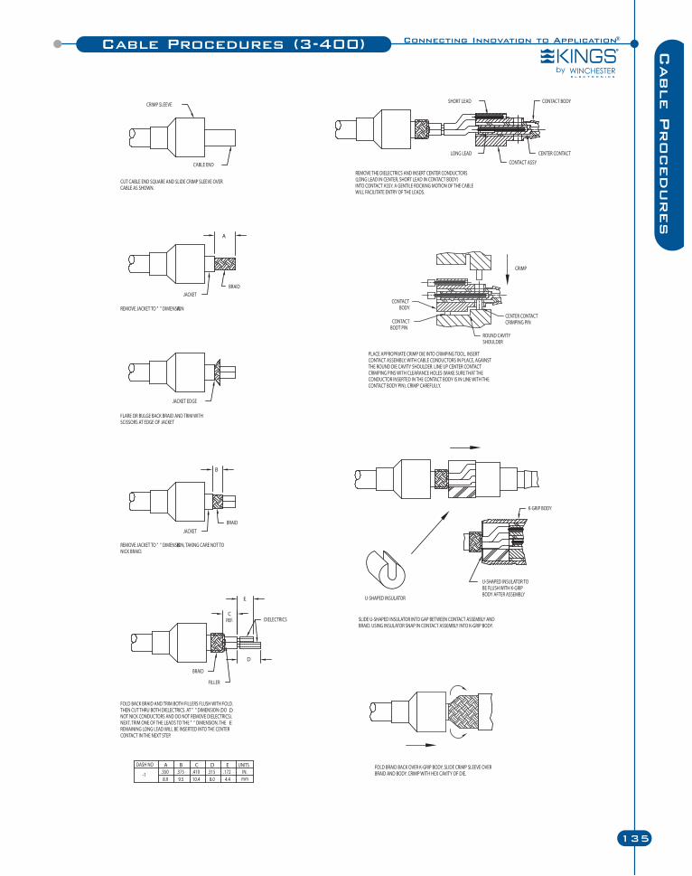
Connecting Innovation to Application®
135
Cable P
rocedures
Cable Procedures (3-400)
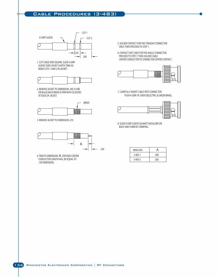
136 Winchester Electronics Corporation | RF Connectors
Cable Procedures (3-483)
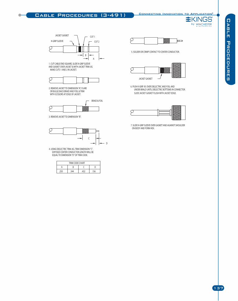
Connecting Innovation to Application®
137
Cable P
rocedures
Cable Procedures (3-491)
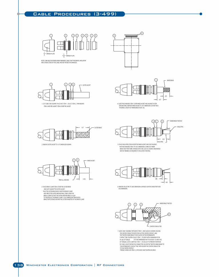
138 Winchester Electronics Corporation | RF Connectors
Cable Procedures (3-499)
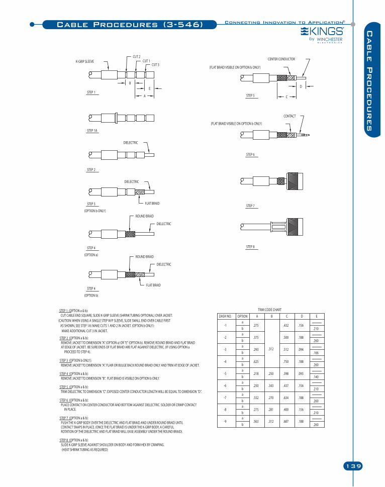
Connecting Innovation to Application®
139
Cable P
rocedures
Cable Procedures (3-546)
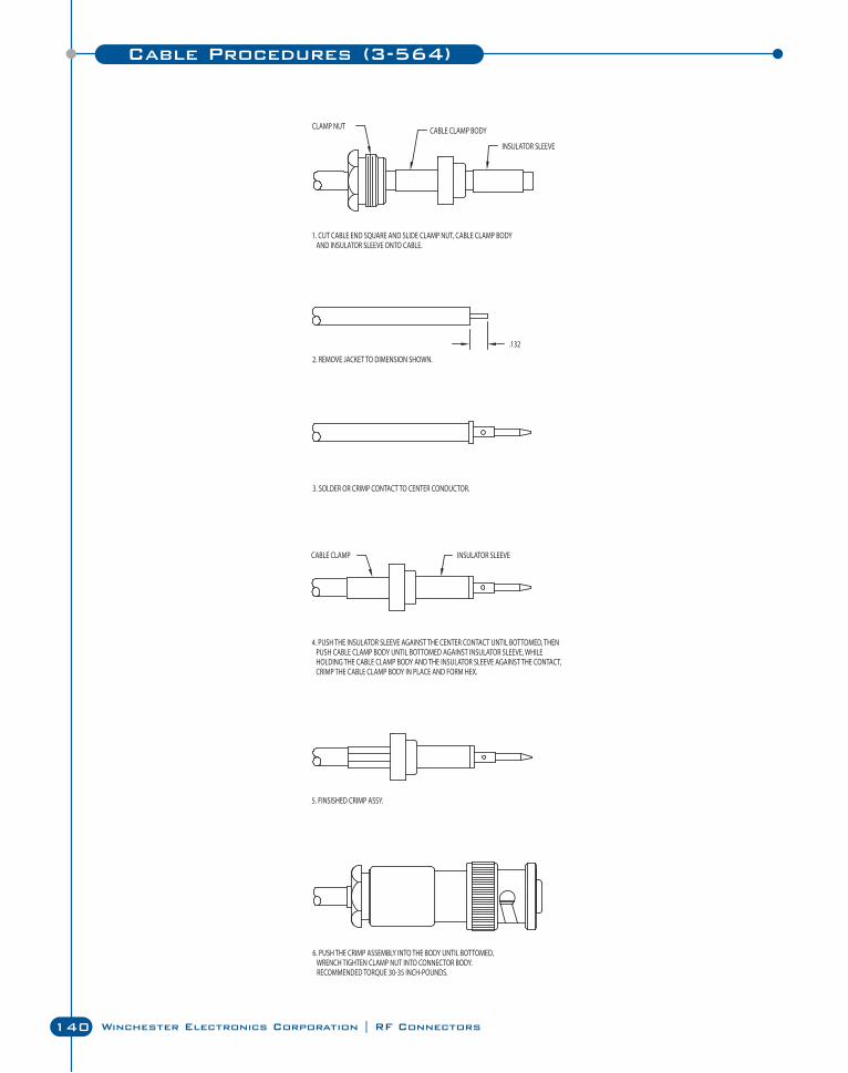
140 Winchester Electronics Corporation | RF Connectors
Cable Procedures (3-564)
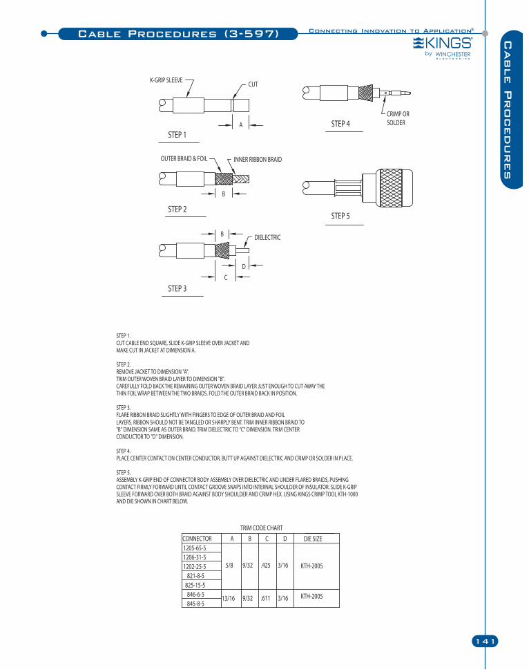
Connecting Innovation to Application®
141
Cable P
rocedures
Cable Procedures (3-597)
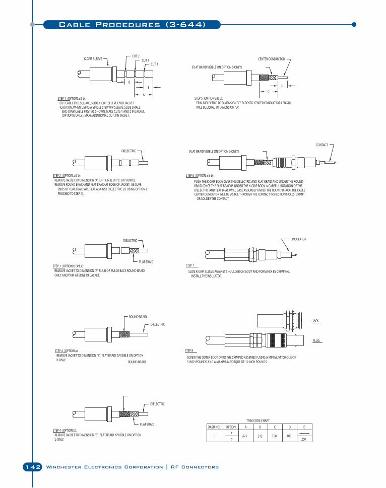
142 Winchester Electronics Corporation | RF Connectors
Cable Procedures (3-644)
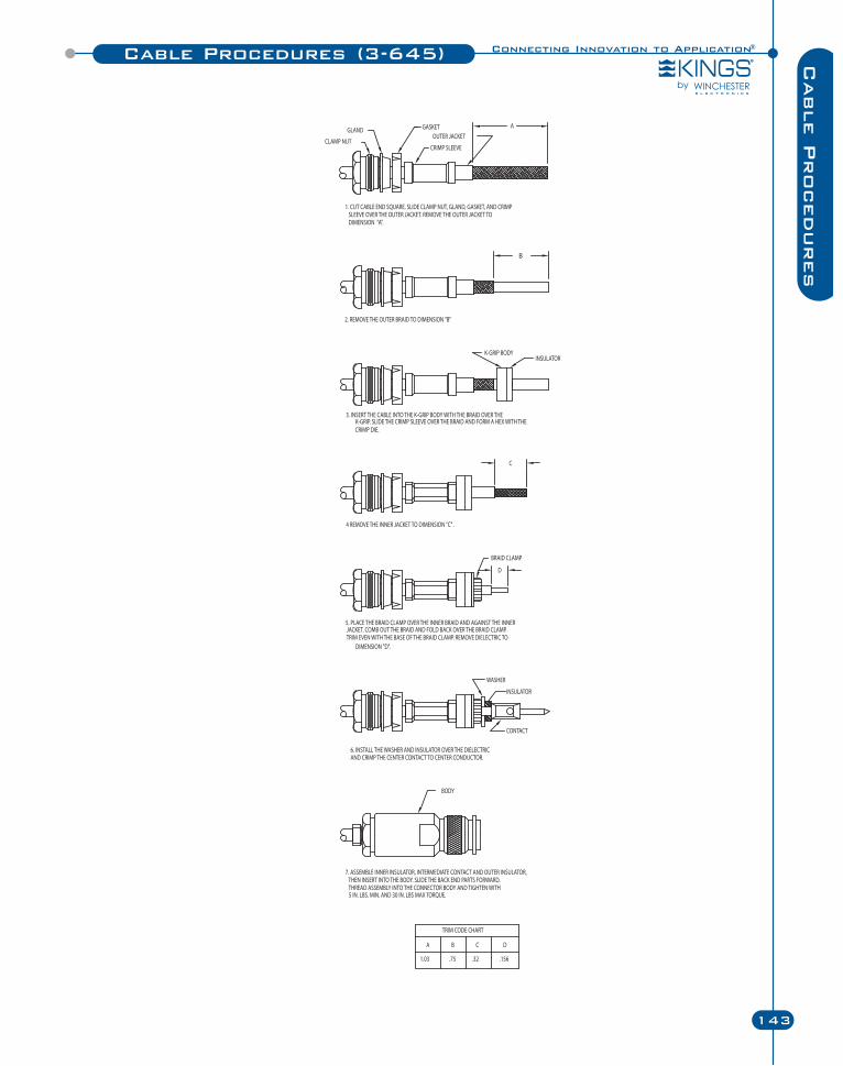
Connecting Innovation to Application®
143
Cable P
rocedures
Cable Procedures (3-645)
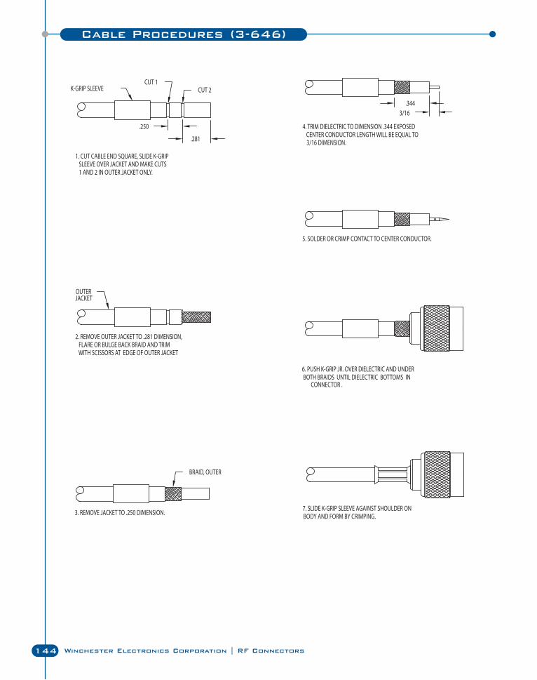
144 Winchester Electronics Corporation | RF Connectors
Cable Procedures (3-646)
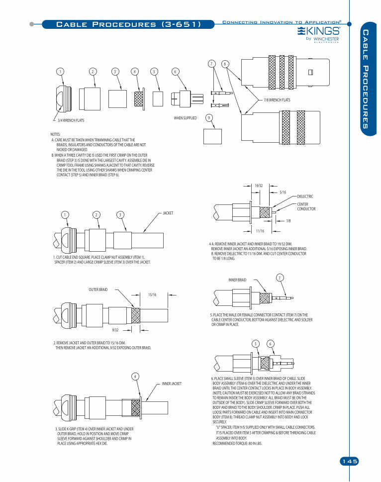
Connecting Innovation to Application®
145
Cable P
rocedures
Cable Procedures (3-651)
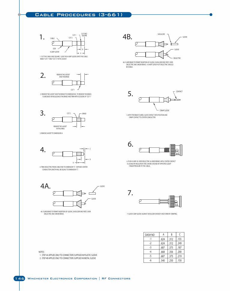
146 Winchester Electronics Corporation | RF Connectors
Cable Procedures (3-661)
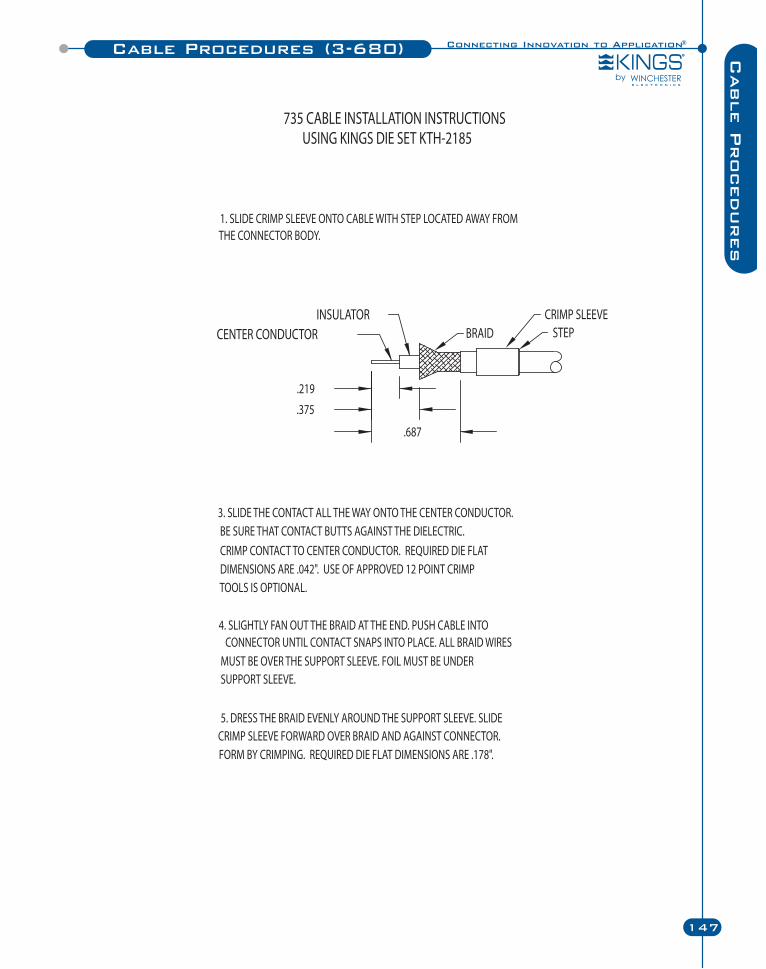
Connecting Innovation to Application®
147
Cable P
rocedures
Cable Procedures (3-680)
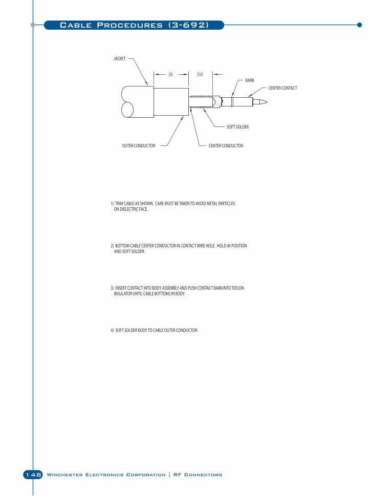
148 Winchester Electronics Corporation | RF Connectors
Cable Procedures (3-692)
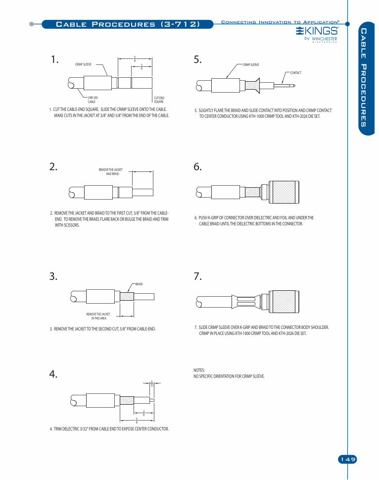
Connecting Innovation to Application®
149
Cable P
rocedures
Cable Procedures (3-712)
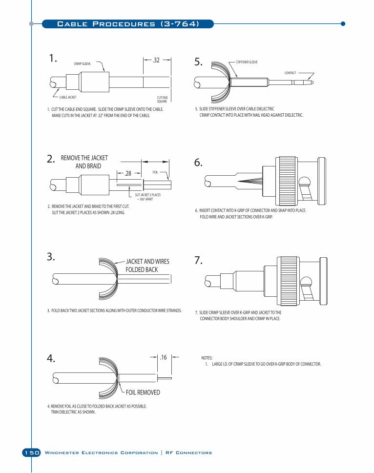
150 Winchester Electronics Corporation | RF Connectors
Cable Procedures (3-764)
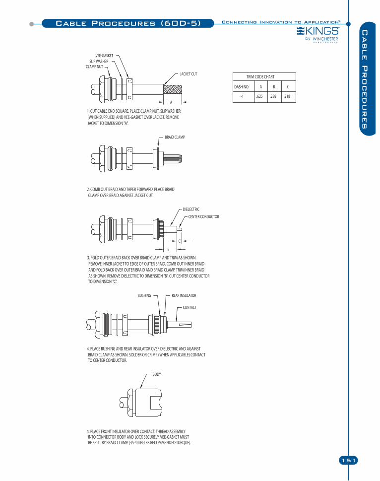
Connecting Innovation to Application®
151
Cable P
rocedures
Cable Procedures (60D-5)
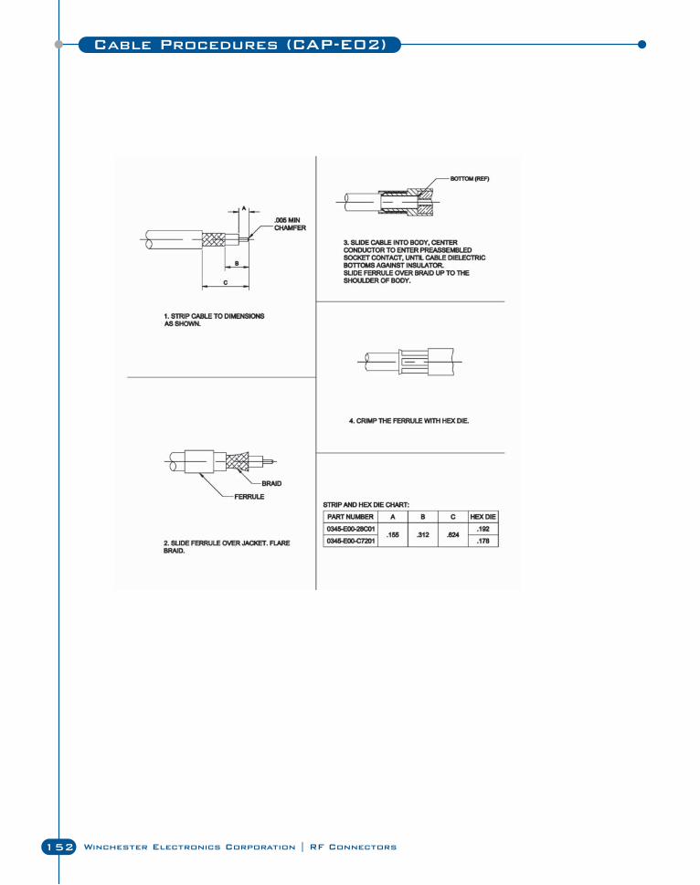
Cable Procedures (CAP-E02)
152 Winchester Electronics Corporation | RF Connectors
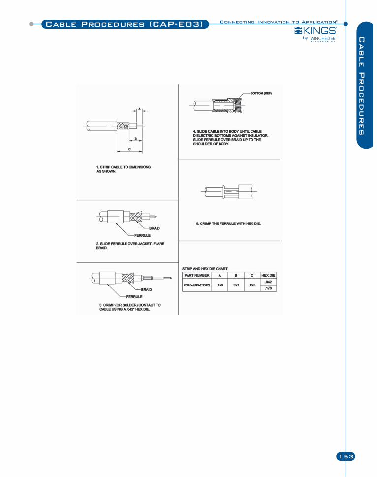
Cable Procedures (CAP-E03)
153
Cable P
rocedures
Connecting Innovation to Application®
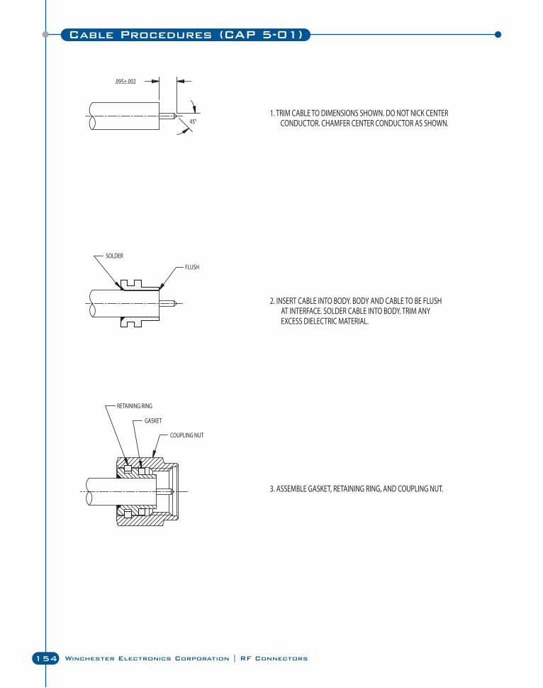
154 Winchester Electronics Corporation | RF Connectors
Cable Procedures (CAP 5-01)
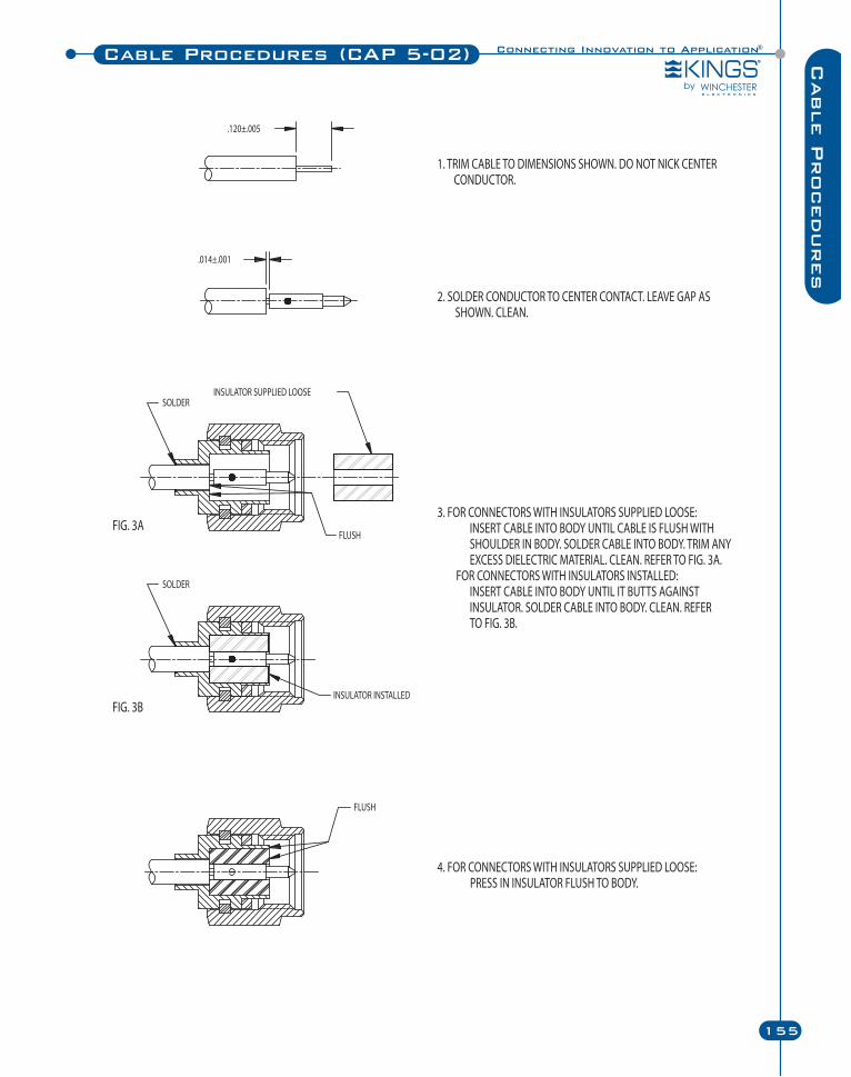
Connecting Innovation to Application®
155
Cable P
rocedures
Cable Procedures (CAP 5-02)
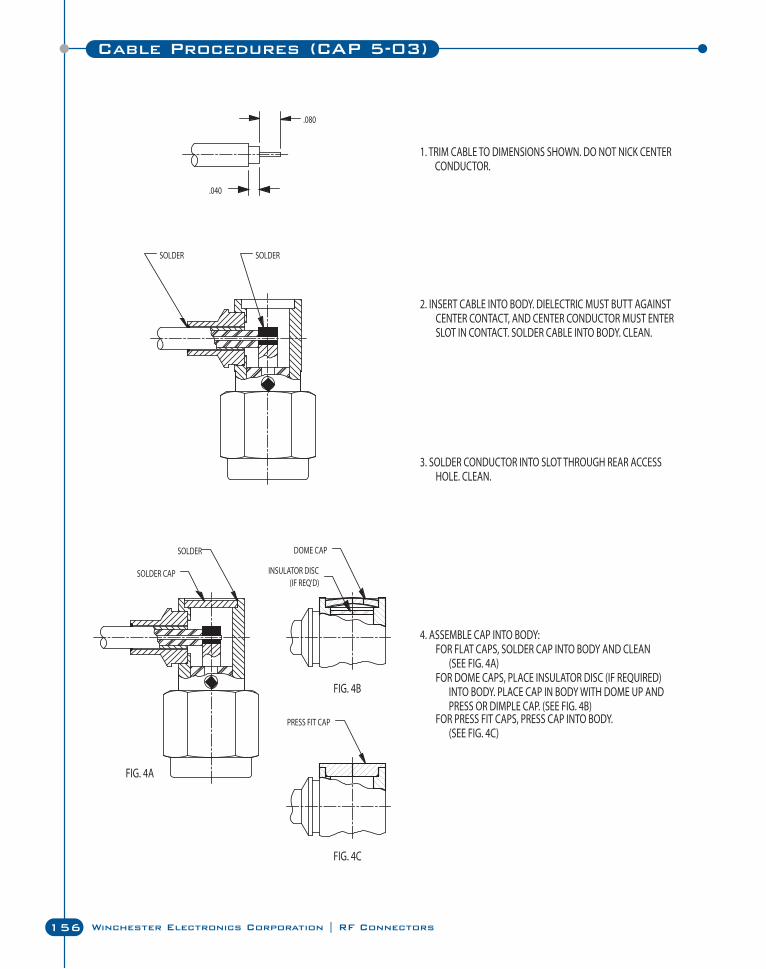
156 Winchester Electronics Corporation | RF Connectors
Cable Procedures (CAP 5-03)
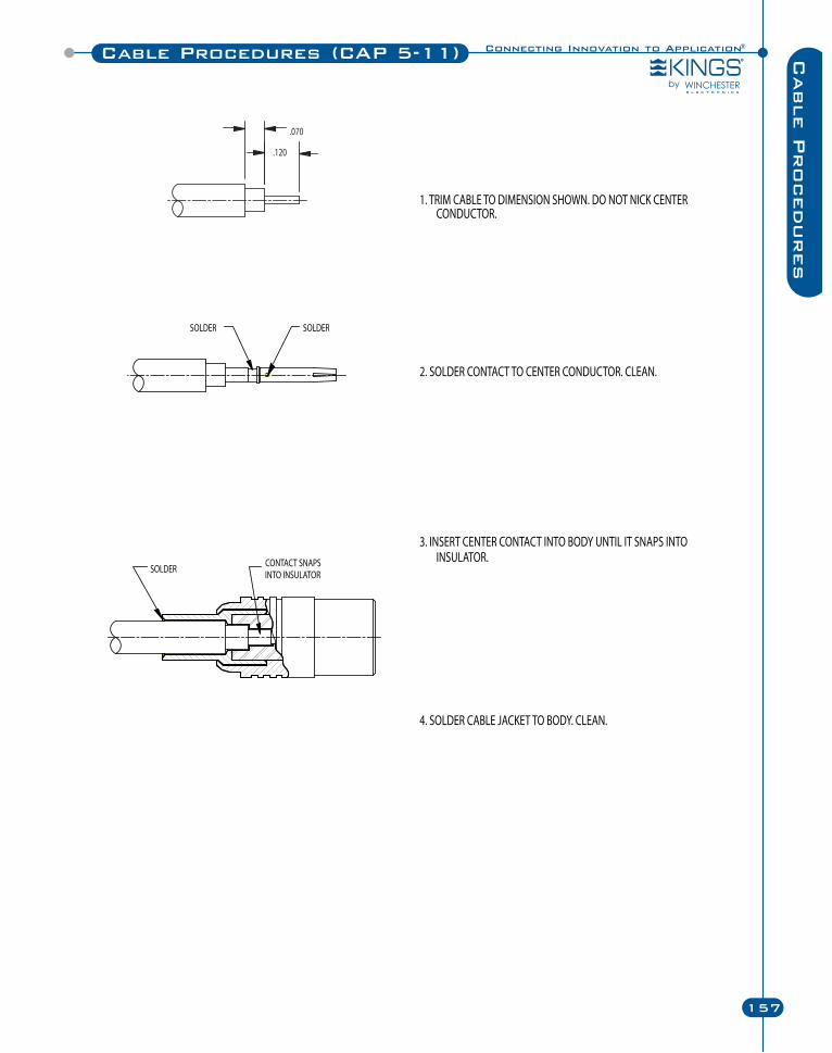
Connecting Innovation to Application®
157
Cable Procedures (CAP 5-11) Cable P
rocedures
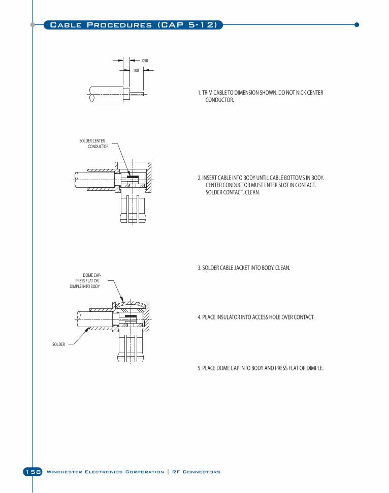
158 Winchester Electronics Corporation | RF Connectors
Cable Procedures (CAP 5-12)
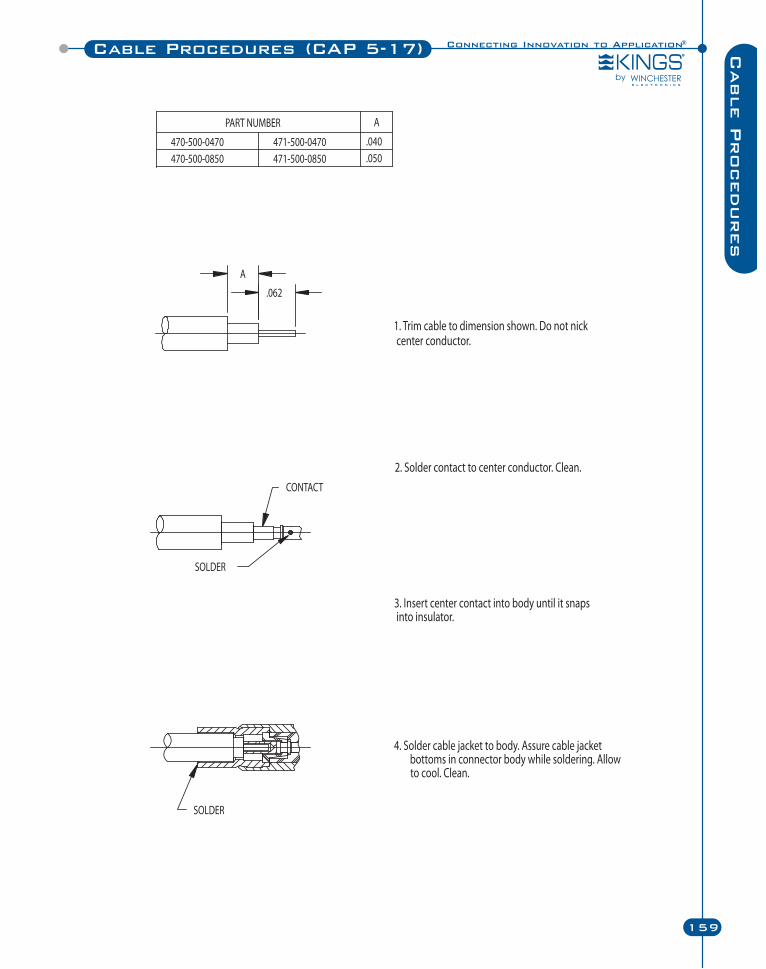
Connecting Innovation to Application®
159
Cable Procedures (CAP 5-17) Cable P
rocedures
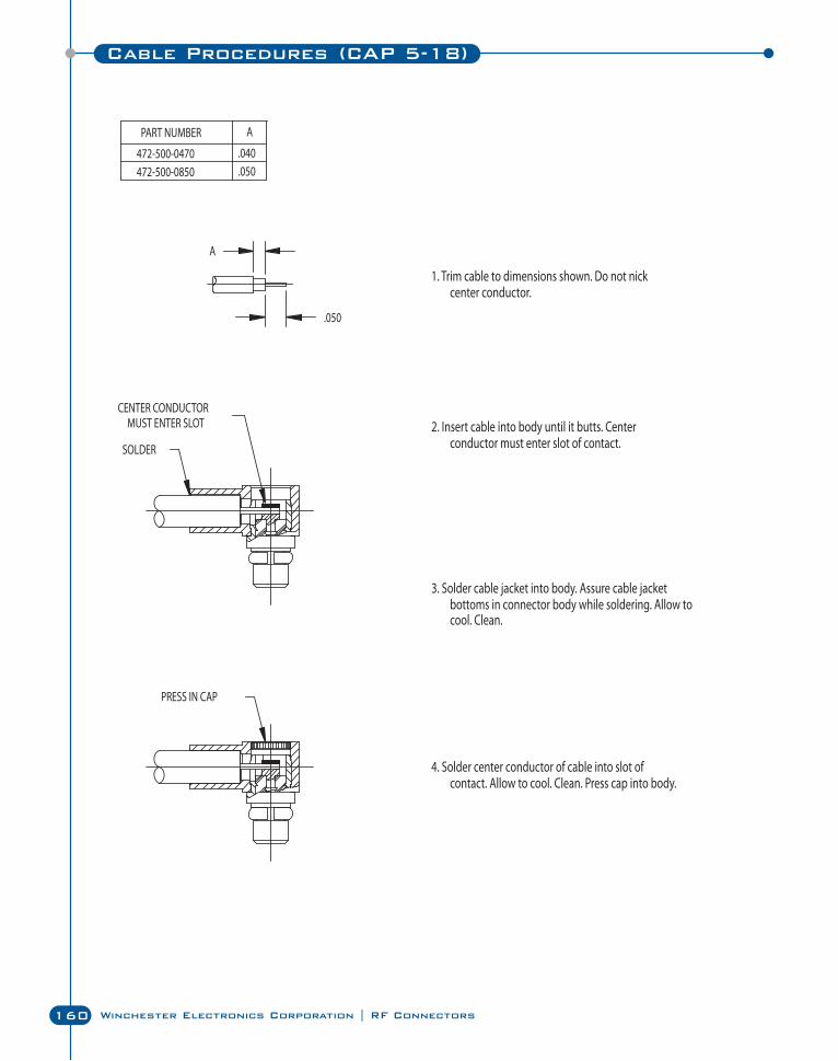
160 Winchester Electronics Corporation | RF Connectors
Cable Procedures (CAP 5-18)
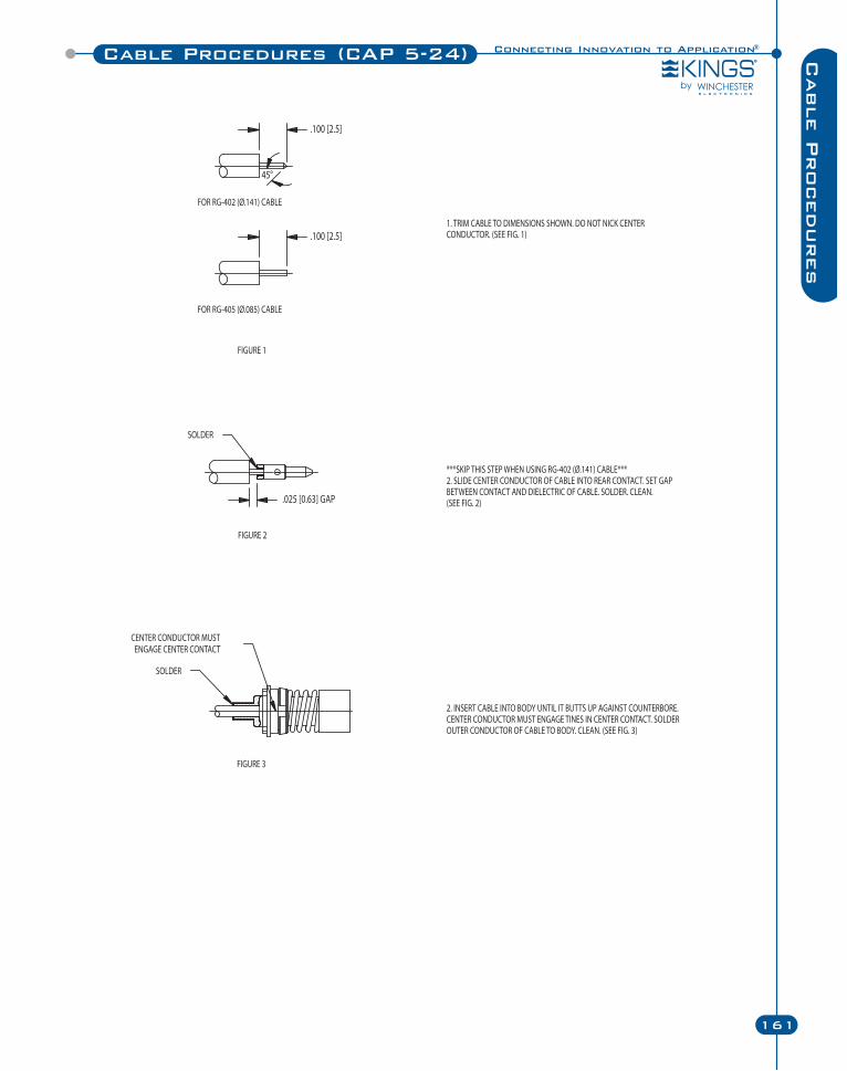
Connecting Innovation to Application®
161
Cable Procedures (CAP 5-24) Cable P
rocedures
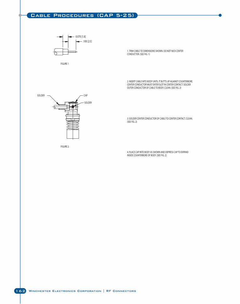
162 Winchester Electronics Corporation | RF Connectors
Cable Procedures (CAP 5-25)
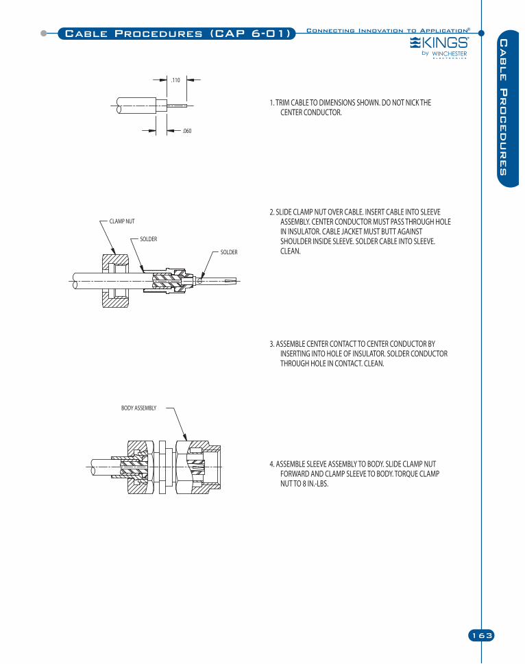
Connecting Innovation to Application®
163
Cable Procedures (CAP 6-01) Cable P
rocedures
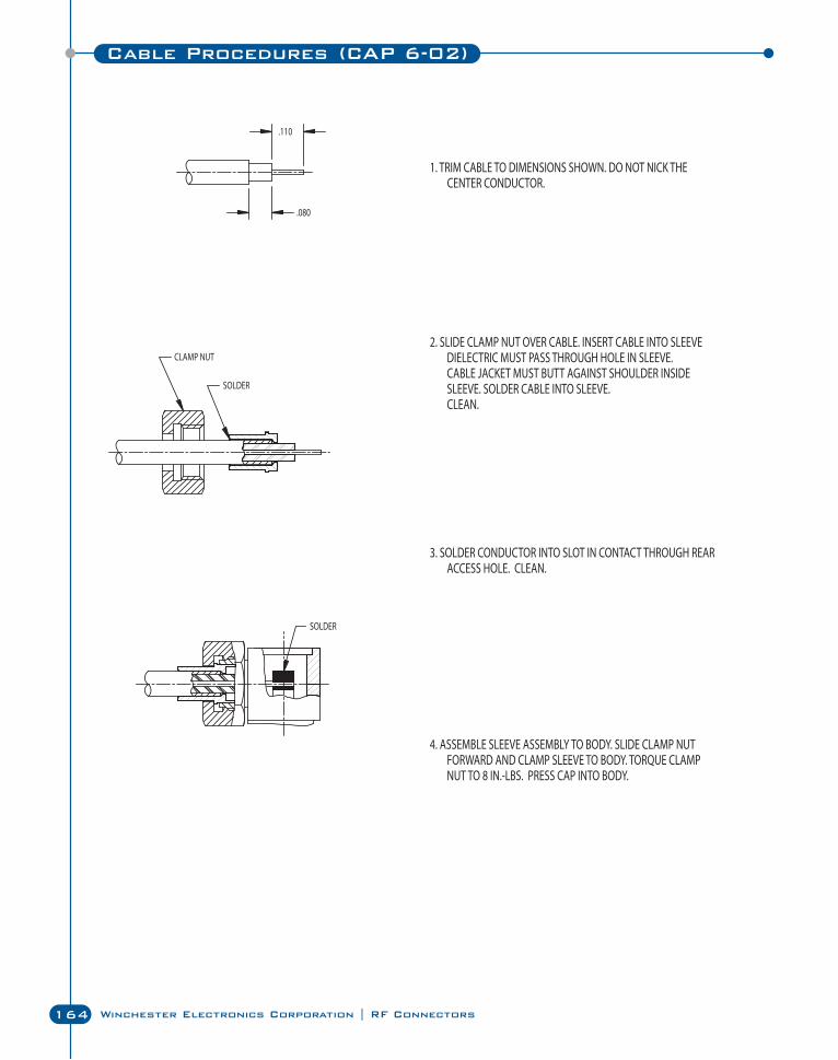
164 Winchester Electronics Corporation | RF Connectors
Cable Procedures (CAP 6-02)
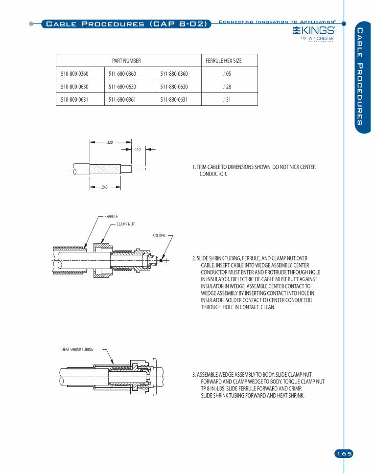
Connecting Innovation to Application®
165
Cable Procedures (CAP 8-02) Cable P
rocedures
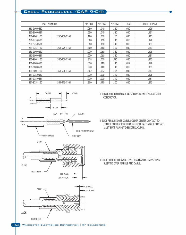
166 Winchester Electronics Corporation | RF Connectors
Cable Procedures (CAP 9-04)
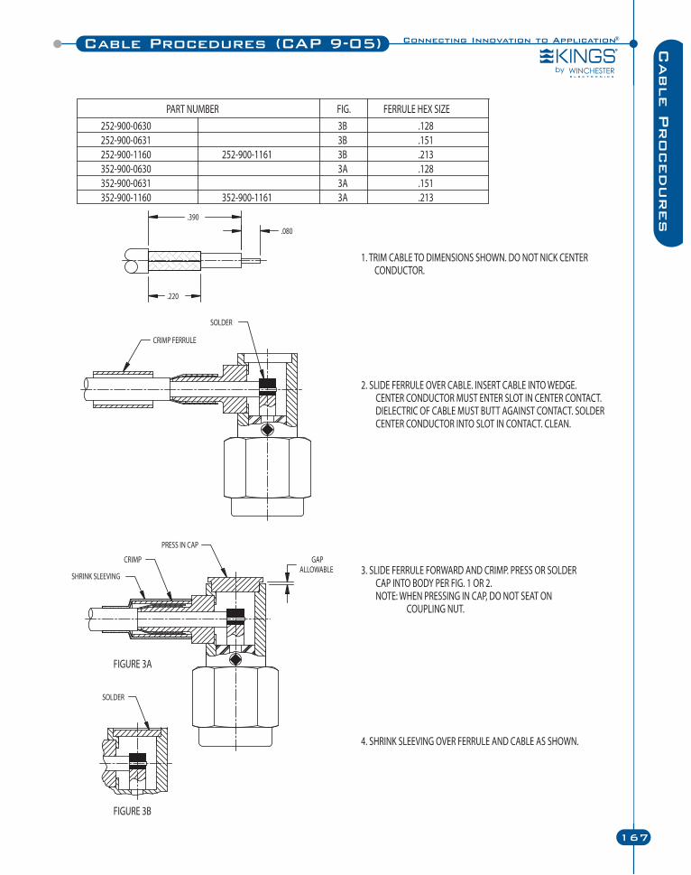
Connecting Innovation to Application®
167
Cable Procedures (CAP 9-05) Cable P
rocedures
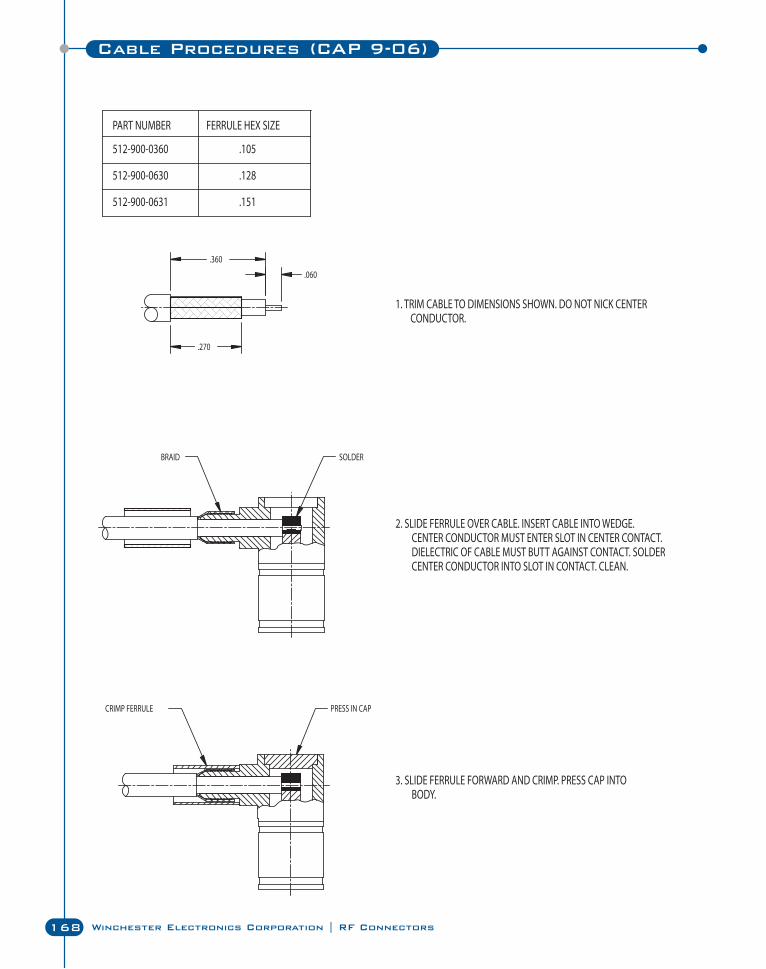
168 Winchester Electronics Corporation | RF Connectors
Cable Procedures (CAP 9-06)
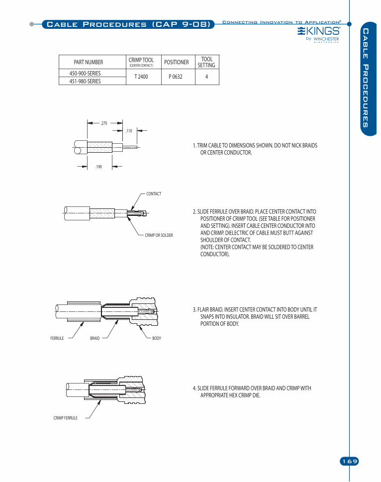
Connecting Innovation to Application®
169
Cable Procedures (CAP 9-08) Cable P
rocedures
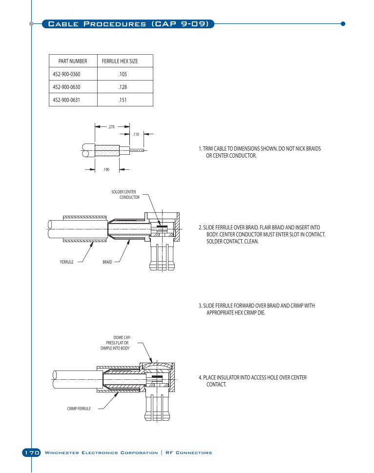
170 Winchester Electronics Corporation | RF Connectors
Cable Procedures (CAP 9-09)
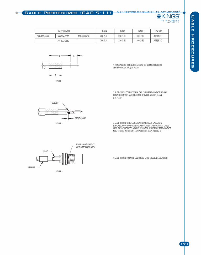
Connecting Innovation to Application®
171
Cable Procedures (CAP 9-11) Cable P
rocedures
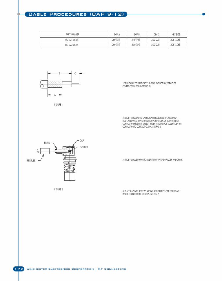
172 Winchester Electronics Corporation | RF Connectors
Cable Procedures (CAP 9-12)
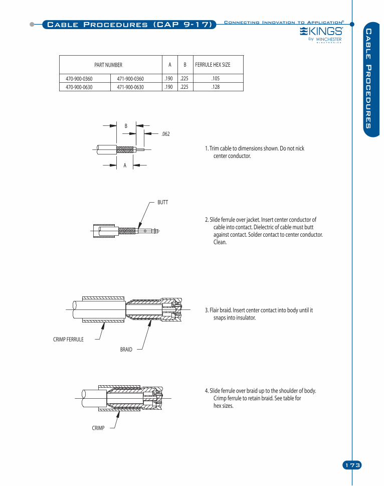
Connecting Innovation to Application®
173
Cable Procedures (CAP 9-17) Cable P
rocedures
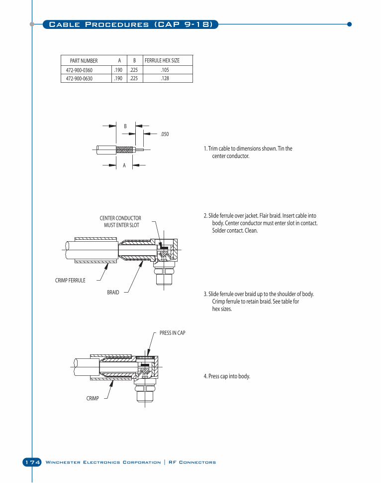
174 Winchester Electronics Corporation | RF Connectors
Cable Procedures (CAP 9-18)
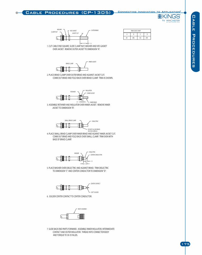
Connecting Innovation to Application®
175
Cable Procedures (CP-1305) Cable P
rocedures
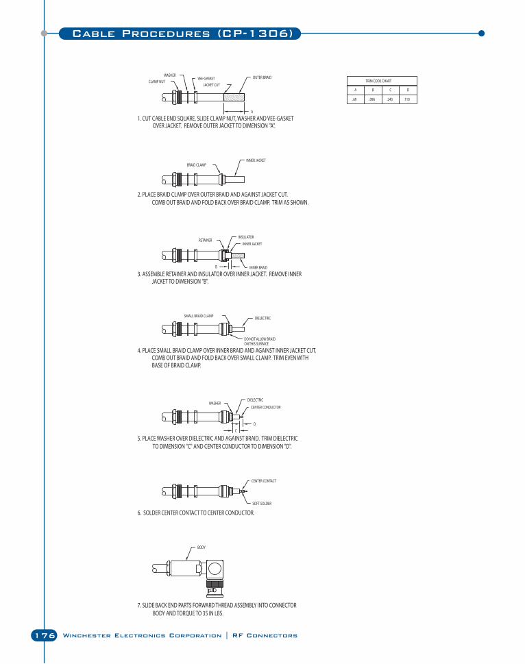
176 Winchester Electronics Corporation | RF Connectors
Cable Procedures (CP-1306)
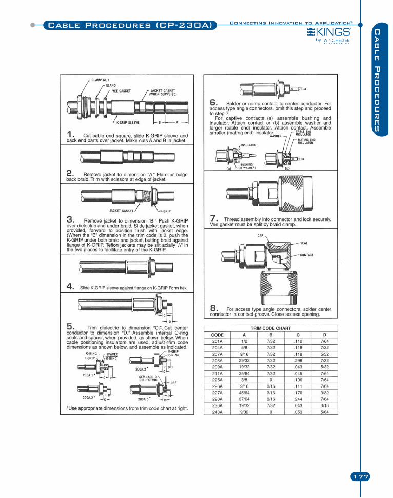
Cable Procedures (CP-230A)
177
Cable P
rocedures
Connecting Innovation to Application®
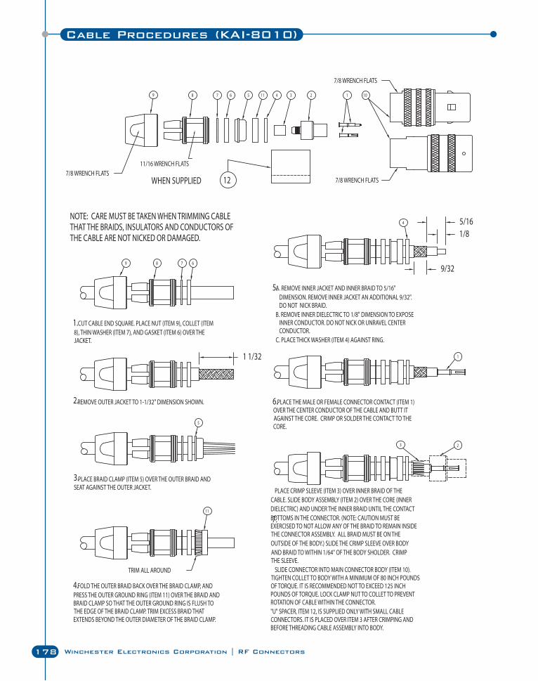
178 Winchester Electronics Corporation | RF Connectors
Cable Procedures (KAI-8010)
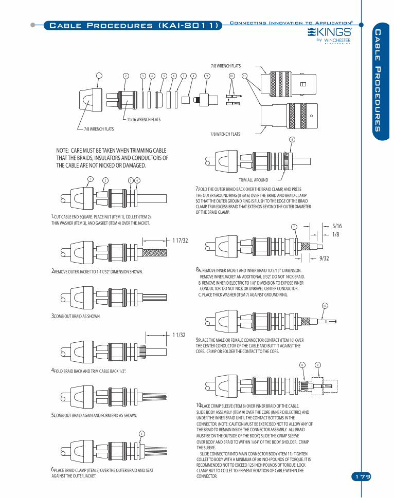
Connecting Innovation to Application®
179
Cable P
rocedures
Cable Procedures (KAI-8011)
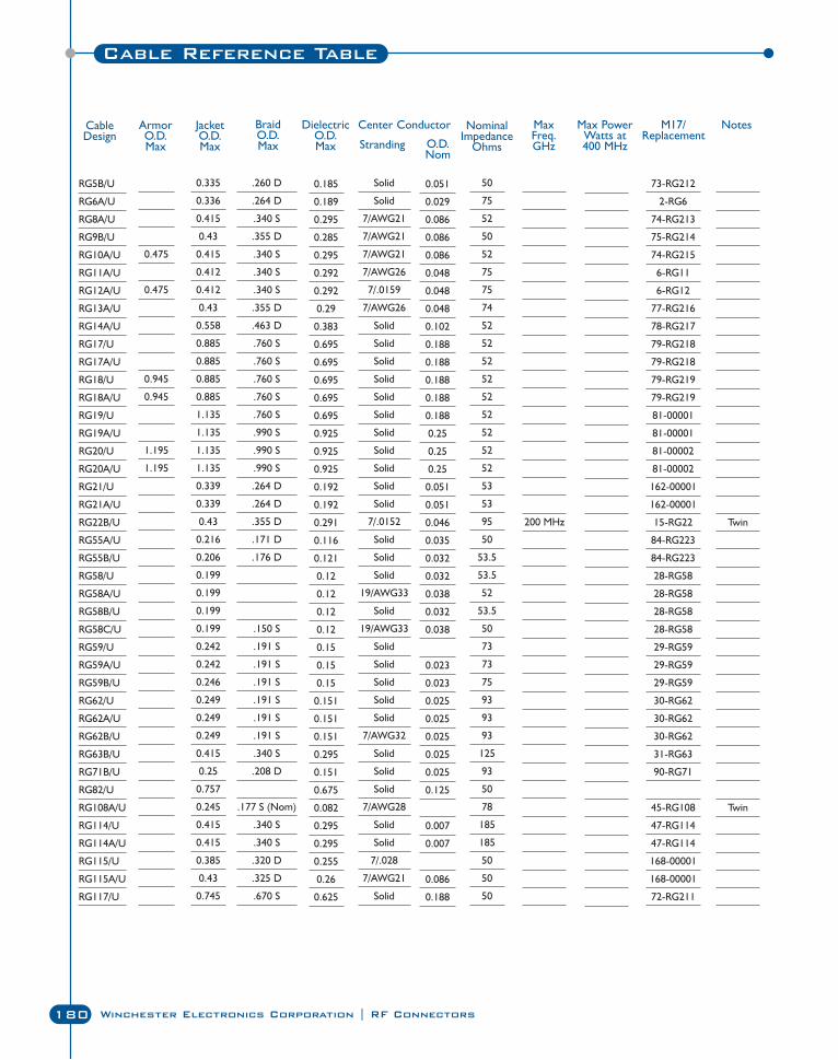
180 Winchester Electronics Corporation | RF Connectors
RG5B/U
RG6A/U
RG8A/U
RG9B/U
RG10A/U
RG11A/U
RG12A/U
RG13A/U
RG14A/U
RG17/U
RG17A/U
RG18/U
RG18A/U
RG19/U
RG19A/U
RG20/U
RG20A/U
RG21/U
RG21A/U
RG22B/U
RG55A/U
RG55B/U
RG58/U
RG58A/U
RG58B/U
RG58C/U
RG59/U
RG59A/U
RG59B/U
RG62/U
RG62A/U
RG62B/U
RG63B/U
RG71B/U
RG82/U
RG108A/U
RG114/U
RG114A/U
RG115/U
RG115A/U
RG117/U
CableDesign
ArmorO.D.Max
JacketO.D.Max
BraidO.D.Max
DielectricO.D.Max
Center Conductor NominalImpedance
Ohms
MaxFreq.GHz
Max PowerWatts at400 MHz
M17/Replacement
Notes
Stranding O.D.Nom
0.475
0.475
0.945
0.945
1.195
1.195
0.335
0.336
0.415
0.43
0.415
0.412
0.412
0.43
0.558
0.885
0.885
0.885
0.885
1.135
1.135
1.135
1.135
0.339
0.339
0.43
0.216
0.206
0.199
0.199
0.199
0.199
0.242
0.242
0.246
0.249
0.249
0.249
0.415
0.25
0.757
0.245
0.415
0.415
0.385
0.43
0.745
.260 D
.264 D
.340 S
.355 D
.340 S
.340 S
.340 S
.355 D
.463 D
.760 S
.760 S
.760 S
.760 S
.760 S
.990 S
.990 S
.990 S
.264 D
.264 D
.355 D
.171 D
.176 D
.150 S
.191 S
.191 S
.191 S
.191 S
.191 S
.191 S
.340 S
.208 D
.177 S (Nom)
.340 S
.340 S
.320 D
.325 D
.670 S
0.185
0.189
0.295
0.285
0.295
0.292
0.292
0.29
0.383
0.695
0.695
0.695
0.695
0.695
0.925
0.925
0.925
0.192
0.192
0.291
0.116
0.121
0.12
0.12
0.12
0.12
0.15
0.15
0.15
0.151
0.151
0.151
0.295
0.151
0.675
0.082
0.295
0.295
0.255
0.26
0.625
Solid
Solid
7/AWG21
7/AWG21
7/AWG21
7/AWG26
7/.0159
7/AWG26
Solid
Solid
Solid
Solid
Solid
Solid
Solid
Solid
Solid
Solid
Solid
7/.0152
Solid
Solid
Solid
19/AWG33
Solid
19/AWG33
Solid
Solid
Solid
Solid
Solid
7/AWG32
Solid
Solid
Solid
7/AWG28
Solid
Solid
7/.028
7/AWG21
Solid
0.051
0.029
0.086
0.086
0.086
0.048
0.048
0.048
0.102
0.188
0.188
0.188
0.188
0.188
0.25
0.25
0.25
0.051
0.051
0.046
0.035
0.032
0.032
0.038
0.032
0.038
0.023
0.023
0.025
0.025
0.025
0.025
0.025
0.125
0.007
0.007
0.086
0.188
50
75
52
50
52
75
75
74
52
52
52
52
52
52
52
52
52
53
53
95
50
53.5
53.5
52
53.5
50
73
73
75
93
93
93
125
93
50
78
185
185
50
50
50
200 MHz
73-RG212
2-RG6
74-RG213
75-RG214
74-RG215
6-RG11
6-RG12
77-RG216
78-RG217
79-RG218
79-RG218
79-RG219
79-RG219
81-00001
81-00001
81-00002
81-00002
162-00001
162-00001
15-RG22
84-RG223
84-RG223
28-RG58
28-RG58
28-RG58
28-RG58
29-RG59
29-RG59
29-RG59
30-RG62
30-RG62
30-RG62
31-RG63
90-RG71
45-RG108
47-RG114
47-RG114
168-00001
168-00001
72-RG211
Twin
Twin
Cable Reference Table
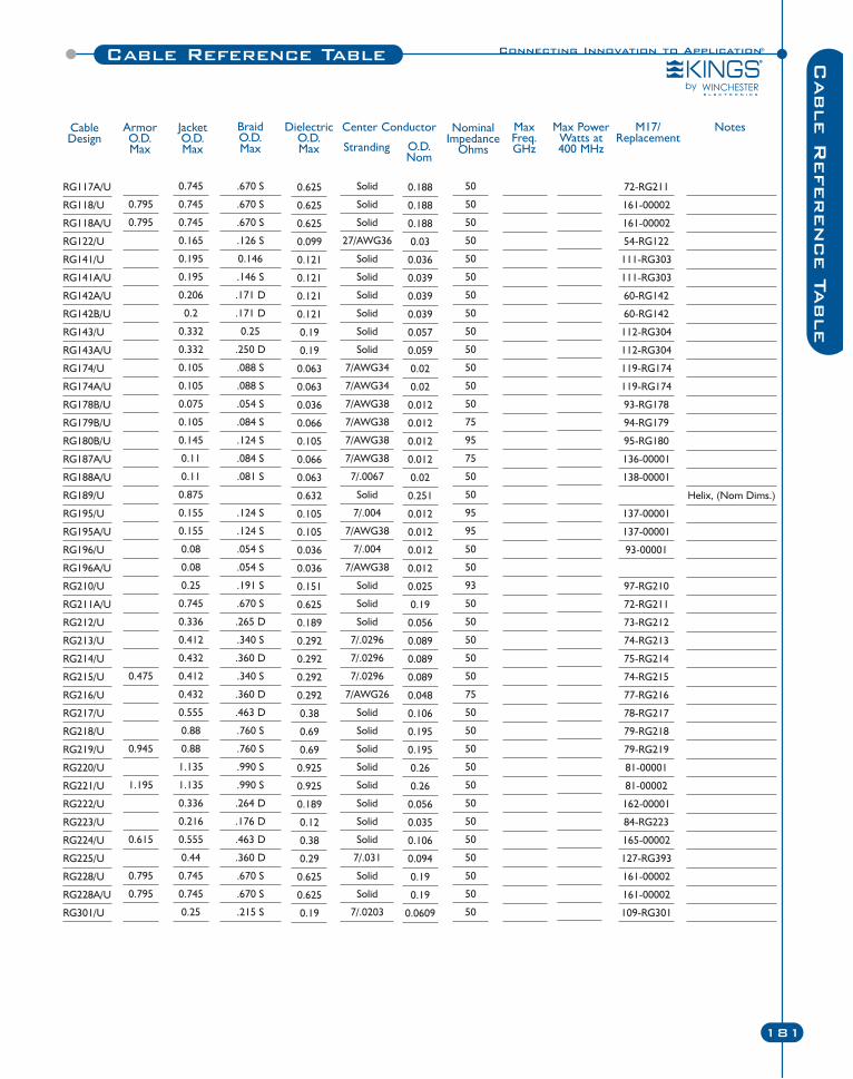
Connecting Innovation to Application®
181
Cable R
eference Ta
ble
Cable Reference Table
RG117A/U
RG118/U
RG118A/U
RG122/U
RG141/U
RG141A/U
RG142A/U
RG142B/U
RG143/U
RG143A/U
RG174/U
RG174A/U
RG178B/U
RG179B/U
RG180B/U
RG187A/U
RG188A/U
RG189/U
RG195/U
RG195A/U
RG196/U
RG196A/U
RG210/U
RG211A/U
RG212/U
RG213/U
RG214/U
RG215/U
RG216/U
RG217/U
RG218/U
RG219/U
RG220/U
RG221/U
RG222/U
RG223/U
RG224/U
RG225/U
RG228/U
RG228A/U
RG301/U
CableDesign
ArmorO.D.Max
JacketO.D.Max
BraidO.D.Max
DielectricO.D.Max
Center Conductor NominalImpedance
Ohms
MaxFreq.GHz
Max PowerWatts at400 MHz
M17/Replacement
Notes
Stranding O.D.Nom
0.795
0.795
0.475
0.945
1.195
0.615
0.795
0.795
0.745
0.745
0.745
0.165
0.195
0.195
0.206
0.2
0.332
0.332
0.105
0.105
0.075
0.105
0.145
0.11
0.11
0.875
0.155
0.155
0.08
0.08
0.25
0.745
0.336
0.412
0.432
0.412
0.432
0.555
0.88
0.88
1.135
1.135
0.336
0.216
0.555
0.44
0.745
0.745
0.25
.670 S
.670 S
.670 S
.126 S
0.146
.146 S
.171 D
.171 D
0.25
.250 D
.088 S
.088 S
.054 S
.084 S
.124 S
.084 S
.081 S
.124 S
.124 S
.054 S
.054 S
.191 S
.670 S
.265 D
.340 S
.360 D
.340 S
.360 D
.463 D
.760 S
.760 S
.990 S
.990 S
.264 D
.176 D
.463 D
.360 D
.670 S
.670 S
.215 S
0.625
0.625
0.625
0.099
0.121
0.121
0.121
0.121
0.19
0.19
0.063
0.063
0.036
0.066
0.105
0.066
0.063
0.632
0.105
0.105
0.036
0.036
0.151
0.625
0.189
0.292
0.292
0.292
0.292
0.38
0.69
0.69
0.925
0.925
0.189
0.12
0.38
0.29
0.625
0.625
0.19
Solid
Solid
Solid
27/AWG36
Solid
Solid
Solid
Solid
Solid
Solid
7/AWG34
7/AWG34
7/AWG38
7/AWG38
7/AWG38
7/AWG38
7/.0067
Solid
7/.004
7/AWG38
7/.004
7/AWG38
Solid
Solid
Solid
7/.0296
7/.0296
7/.0296
7/AWG26
Solid
Solid
Solid
Solid
Solid
Solid
Solid
Solid
7/.031
Solid
Solid
7/.0203
0.188
0.188
0.188
0.03
0.036
0.039
0.039
0.039
0.057
0.059
0.02
0.02
0.012
0.012
0.012
0.012
0.02
0.251
0.012
0.012
0.012
0.012
0.025
0.19
0.056
0.089
0.089
0.089
0.048
0.106
0.195
0.195
0.26
0.26
0.056
0.035
0.106
0.094
0.19
0.19
0.0609
50
50
50
50
50
50
50
50
50
50
50
50
50
75
95
75
50
50
95
95
50
50
93
50
50
50
50
50
75
50
50
50
50
50
50
50
50
50
50
50
50
72-RG211
161-00002
161-00002
54-RG122
111-RG303
111-RG303
60-RG142
60-RG142
112-RG304
112-RG304
119-RG174
119-RG174
93-RG178
94-RG179
95-RG180
136-00001
138-00001
137-00001
137-00001
93-00001
97-RG210
72-RG211
73-RG212
74-RG213
75-RG214
74-RG215
77-RG216
78-RG217
79-RG218
79-RG219
81-00001
81-00002
162-00001
84-RG223
165-00002
127-RG393
161-00002
161-00002
109-RG301
Helix, (Nom Dims.)
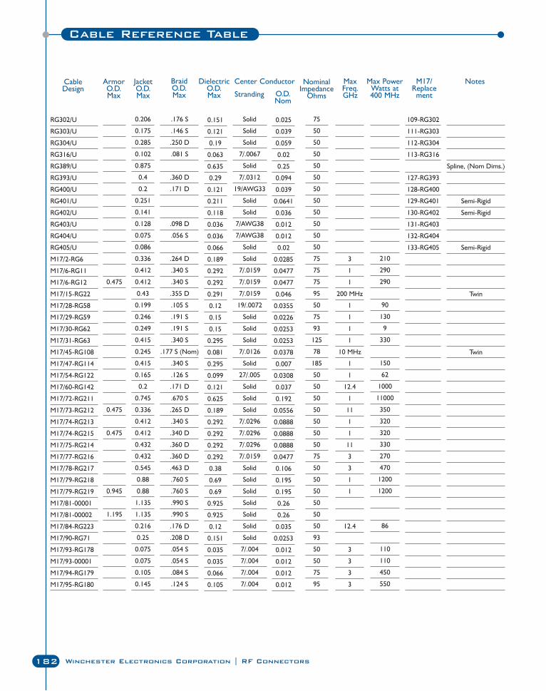
182 Winchester Electronics Corporation | RF Connectors
Cable Reference Table
RG302/U
RG303/U
RG304/U
RG316/U
RG389/U
RG393/U
RG400/U
RG401/U
RG402/U
RG403/U
RG404/U
RG405/U
M17/2-RG6
M17/6-RG11
M17/6-RG12
M17/15-RG22
M17/28-RG58
M17/29-RG59
M17/30-RG62
M17/31-RG63
M17/45-RG108
M17/47-RG114
M17/54-RG122
M17/60-RG142
M17/72-RG211
M17/73-RG212
M17/74-RG213
M17/74-RG215
M17/75-RG214
M17/77-RG216
M17/78-RG217
M17/79-RG218
M17/79-RG219
M17/81-00001
M17/81-00002
M17/84-RG223
M17/90-RG71
M17/93-RG178
M17/93-00001
M17/94-RG179
M17/95-RG180
CableDesign
ArmorO.D.Max
JacketO.D.Max
BraidO.D.Max
DielectricO.D.Max
Center Conductor NominalImpedance
Ohms
MaxFreq.GHz
Max PowerWatts at400 MHz
M17/Replacement
Notes
Stranding O.D.Nom
0.475
0.475
0.475
0.945
1.195
0.206
0.175
0.285
0.102
0.875
0.4
0.2
0.251
0.141
0.128
0.075
0.086
0.336
0.412
0.412
0.43
0.199
0.246
0.249
0.415
0.245
0.415
0.165
0.2
0.745
0.336
0.412
0.412
0.432
0.432
0.545
0.88
0.88
1.135
1.135
0.216
0.25
0.075
0.075
0.105
0.145
.176 S
.146 S
.250 D
.081 S
.360 D
.171 D
.098 D
.056 S
.264 D
.340 S
.340 S
.355 D
.105 S
.191 S
.191 S
.340 S
.177 S (Nom)
.340 S
.126 S
.171 D
.670 S
.265 D
.340 S
.340 D
.360 D
.360 D
.463 D
.760 S
.760 S
.990 S
.990 S
.176 D
.208 D
.054 S
.054 S
.084 S
.124 S
0.151
0.121
0.19
0.063
0.635
0.29
0.121
0.211
0.118
0.036
0.036
0.066
0.189
0.292
0.292
0.291
0.12
0.15
0.15
0.295
0.081
0.295
0.099
0.121
0.625
0.189
0.292
0.292
0.292
0.292
0.38
0.69
0.69
0.925
0.925
0.12
0.151
0.035
0.035
0.066
0.105
Solid
Solid
Solid
7/.0067
Solid
7/.0312
19/AWG33
Solid
Solid
7/AWG38
7/AWG38
Solid
Solid
7/.0159
7/.0159
7/.0159
19/.0072
Solid
Solid
Solid
7/.0126
Solid
27/.005
Solid
Solid
Solid
7/.0296
7/.0296
7/.0296
7/.0159
Solid
Solid
Solid
Solid
Solid
Solid
Solid
7/.004
7/.004
7/.004
7/.004
0.025
0.039
0.059
0.02
0.25
0.094
0.039
0.0641
0.036
0.012
0.012
0.02
0.0285
0.0477
0.0477
0.046
0.0355
0.0226
0.0253
0.0253
0.0378
0.007
0.0308
0.037
0.192
0.0556
0.0888
0.0888
0.0888
0.0477
0.106
0.195
0.195
0.26
0.26
0.035
0.0253
0.012
0.012
0.012
0.012
75
50
50
50
50
50
50
50
50
50
50
50
75
75
75
95
50
75
93
125
78
185
50
50
50
50
50
50
50
75
50
50
50
50
50
50
93
50
50
75
95
3
1
1
200 MHz
1
1
1
1
10 MHz
1
1
12.4
1
11
1
1
11
3
3
1
1
12.4
3
3
3
3
210
290
290
90
130
9
330
150
62
1000
11000
350
320
320
330
270
470
1200
1200
86
110
110
450
550
109-RG302
111-RG303
112-RG304
113-RG316
127-RG393
128-RG400
129-RG401
130-RG402
131-RG403
132-RG404
133-RG405
Spline, (Nom Dims.)
Semi-Rigid
Semi-Rigid
Semi-Rigid
Twin
Twin
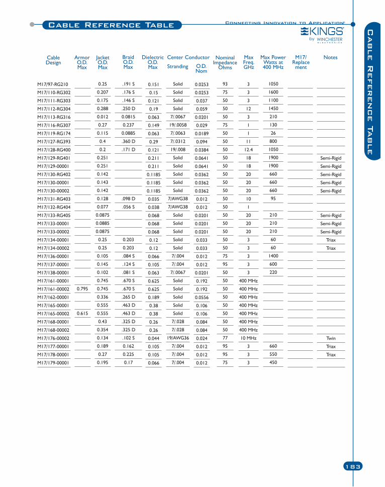
Connecting Innovation to Application®
183
Cable Reference Table Cable R
eference Ta
ble
M17/97-RG210
M17/110-RG302
M17/111-RG303
M17/112-RG304
M17/113-RG316
M17/116-RG307
M17/119-RG174
M17/127-RG393
M17/128-RG400
M17/129-RG401
M17/129-00001
M17/130-RG402
M17/130-00001
M17/130-00002
M17/131-RG403
M17/132-RG404
M17/133-RG405
M17/133-00001
M17/133-00002
M17/134-00001
M17/134-00002
M17/136-00001
M17/137-00001
M17/138-00001
M17/161-00001
M17/161-00002
M17/162-00001
M17/165-00001
M17/165-00002
M17/168-00001
M17/168-00002
M17/176-00002
M17/177-00001
M17/178-00001
M17/179-00001
CableDesign
ArmorO.D.Max
JacketO.D.Max
BraidO.D.Max
DielectricO.D.Max
Center Conductor NominalImpedance
Ohms
MaxFreq.GHz
Max PowerWatts at400 MHz
M17/Replacement
Notes
Stranding O.D.Nom
0.795
0.615
0.25
0.207
0.175
0.288
0.012
0.27
0.115
0.4
0.2
0.251
0.251
0.142
0.143
0.142
0.128
0.077
0.0875
0.0885
0.0875
0.25
0.25
0.105
0.145
0.102
0.745
0.745
0.336
0.555
0.555
0.43
0.354
0.134
0.189
0.27
0.195
.191 S
.176 S
.146 S
.250 D
0.0815
0.237
0.0885
.360 D
.171 D
.098 D
.056 S
0.203
0.203
.084 S
.124 S
.081 S
.670 S
.670 S
.265 D
.463 D
.463 D
.325 D
.325 D
.102 S
0.162
0.225
0.17
0.151
0.15
0.121
0.19
0.063
0.149
0.063
0.29
0.121
0.211
0.211
0.1185
0.1185
0.1185
0.035
0.038
0.068
0.068
0.068
0.12
0.12
0.066
0.105
0.063
0.625
0.625
0.189
0.38
0.38
0.26
0.26
0.044
0.105
0.105
0.066
Solid
Solid
Solid
Solid
7/.0067
19/.0058
7/.0063
7/.0312
19/.008
Solid
Solid
Solid
Solid
Solid
7/AWG38
7/AWG38
Solid
Solid
Solid
Solid
Solid
7/.004
7/.004
7/.0067
Solid
Solid
Solid
Solid
Solid
7/.028
7/.028
19/AWG36
7/.004
7/.004
7/.004
0.0253
0.0253
0.037
0.059
0.0201
0.029
0.0189
0.094
0.0384
0.0641
0.0641
0.0362
0.0362
0.0362
0.012
0.012
0.0201
0.0201
0.0201
0.033
0.033
0.012
0.012
0.0201
0.192
0.192
0.0556
0.106
0.106
0.084
0.084
0.024
0.012
0.012
0.012
93
75
50
50
50
75
50
50
50
50
50
50
50
50
50
50
50
50
50
50
50
75
95
50
50
50
50
50
50
50
50
77
95
95
75
3
3
3
12
3
1
1
11
12.4
18
18
20
20
20
10
1
20
20
20
3
3
3
3
3
400 MHz
400 MHz
400 MHz
400 MHz
400 MHz
400 MHz
400 MHz
10 MHz
3
3
3
1050
1600
1100
1450
210
130
26
800
1050
1900
1900
660
660
660
95
210
210
210
60
60
1400
600
220
660
550
450
Semi-Rigid
Semi-Rigid
Semi-Rigid
Semi-Rigid
Semi-Rigid
Semi-Rigid
Semi-Rigid
Semi-Rigid
Triax
Triax
Twin
Triax
Triax
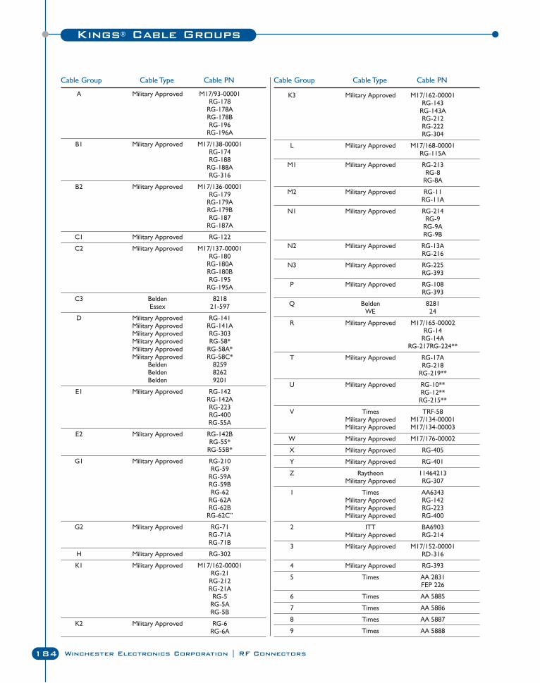
184 Winchester Electronics Corporation | RF Connectors
A Military Approved M17/93-00001RG-178
RG-178ARG-178BRG-196
RG-196A
B1 Military Approved M17/138-00001RG-174RG-188
RG-188ARG-316
B2 Military Approved M17/136-00001RG-179
RG-179ARG-179BRG-187
RG-187A
C1 Military Approved RG-122
C2 Military Approved M17/137-00001RG-180
RG-180ARG-180BRG-195
RG-195A
C3 Belden 8218Essex 21-597
D Military Approved RG-141Military Approved RG-141AMilitary Approved RG-303Military Approved RG-58*Military Approved RG-58A*Military Approved RG-58C*
Belden 8259Belden 8262Belden 9201
E1 Military Approved RG-142RG-142ARG-223RG-400RG-55A
E2 Military Approved RG-142BRG-55*
RG-55B*
G1 Military Approved RG-210RG-59
RG-59ARG-59BRG-62
RG-62ARG-62B
RG-62C”
G2 Military Approved RG-71RG-71ARG-71B
H Military Approved RG-302
K1 Military Approved M17/162-00001RG-21
RG-212RG-21A
RG-5RG-5ARG-5B
K2 Military Approved RG-6RG-6A
Cable Group Cable Type Cable PN
K3 Military Approved M17/162-00001RG-143
RG-143ARG-212RG-222RG-304
L Military Approved M17/168-00001RG-115A
M1 Military Approved RG-213RG-8
RG-8A
M2 Military Approved RG-11RG-11A
N1 Military Approved RG-214RG-9
RG-9ARG-9B
N2 Military Approved RG-13ARG-216
N3 Military Approved RG-225RG-393
P Military Approved RG-108RG-393
Q Belden 8281WE 24
R Military Approved M17/165-00002RG-14
RG-14ARG-217RG-224**
T Military Approved RG-17ARG-218
RG-219**
U Military Approved RG-10**RG-12**
RG-215**
V Times TRF-58Military Approved M17/134-00001Military Approved M17/134-00003
W Military Approved M17/176-00002
X Military Approved RG-405
Y Military Approved RG-401
Z Raytheon 11464213Military Approved RG-307
1 Times AA6343Military Approved RG-142Military Approved RG-223Military Approved RG-400
2 ITT BA6903Military Approved RG-214
3 Military Approved M17/152-00001RD-316
4 Military Approved RG-393
5 Times AA 2831FEP 226
6 Times AA 5885
7 Times AA 5886
8 Times AA 5887
9 Times AA 5888
Cable Group Cable Type Cable PN
Kings® Cable Groups
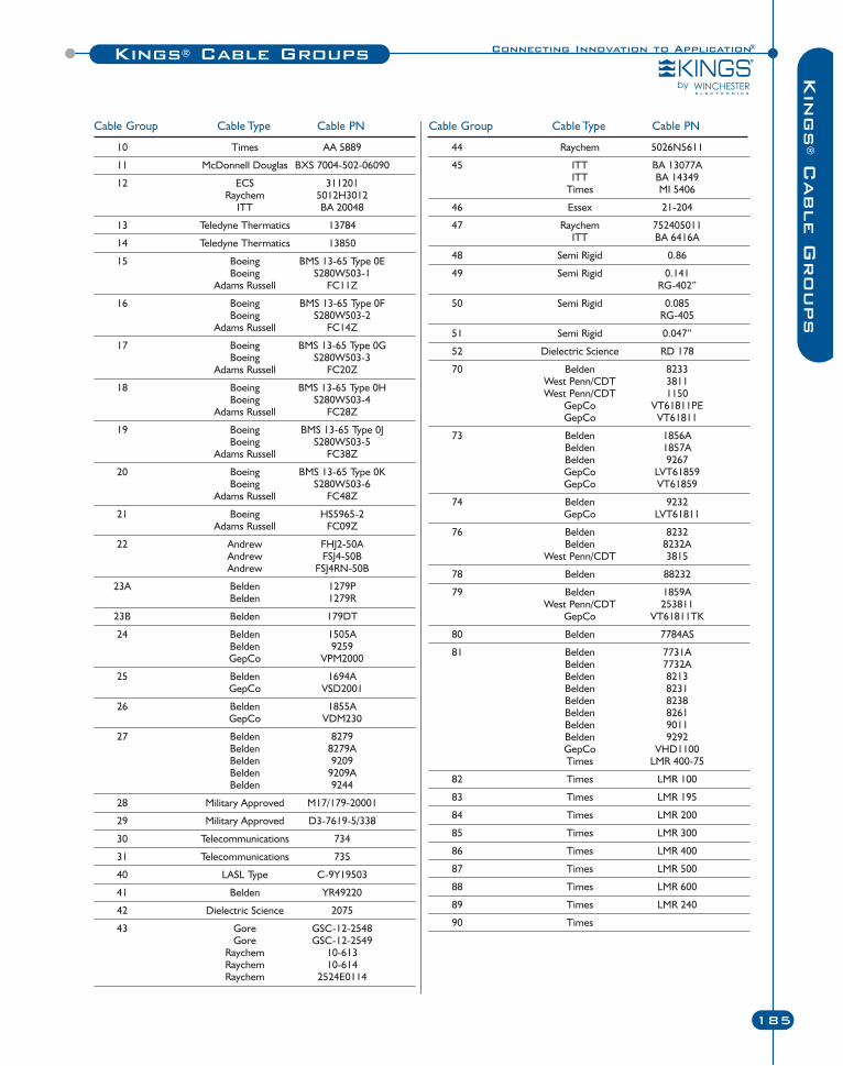
Connecting Innovation to Application®
185
Kin
gs
®C
able G
roups
Kings® Cable Groups
10 Times AA 5889
11 McDonnell Douglas BXS 7004-502-06090
12 ECS 311201Raychem 5012H3012
ITT BA 20048
13 Teledyne Thermatics 13784
14 Teledyne Thermatics 13850
15 Boeing BMS 13-65 Type 0EBoeing S280W503-1
Adams Russell FC11Z
16 Boeing BMS 13-65 Type 0FBoeing S280W503-2
Adams Russell FC14Z
17 Boeing BMS 13-65 Type 0GBoeing S280W503-3
Adams Russell FC20Z
18 Boeing BMS 13-65 Type 0HBoeing S280W503-4
Adams Russell FC28Z
19 Boeing BMS 13-65 Type 0JBoeing S280W503-5
Adams Russell FC38Z
20 Boeing BMS 13-65 Type 0KBoeing S280W503-6
Adams Russell FC48Z
21 Boeing HS5965-2Adams Russell FC09Z
22 Andrew FHJ2-50AAndrew FSJ4-50BAndrew FSJ4RN-50B
23A Belden 1279PBelden 1279R
23B Belden 179DT
24 Belden 1505ABelden 9259GepCo VPM2000
25 Belden 1694AGepCo VSD2001
26 Belden 1855AGepCo VDM230
27 Belden 8279Belden 8279ABelden 9209Belden 9209ABelden 9244
28 Military Approved M17/179-20001
29 Military Approved D3-7619-5/338
30 Telecommunications 734
31 Telecommunications 735
40 LASL Type C-9Y19503
41 Belden YR49220
42 Dielectric Science 2075
43 Gore GSC-12-2548Gore GSC-12-2549
Raychem 10-613Raychem 10-614Raychem 2524E0114
Cable Group Cable Type Cable PN
44 Raychem 5026N5611
45 ITT BA 13077AITT BA 14349
Times MI 5406
46 Essex 21-204
47 Raychem 752405011ITT BA 6416A
48 Semi Rigid 0.86
49 Semi Rigid 0.141RG-402”
50 Semi Rigid 0.085RG-405
51 Semi Rigid 0.047”
52 Dielectric Science RD 178
70 Belden 8233West Penn/CDT 3811West Penn/CDT 1150
GepCo VT61811PEGepCo VT61811
73 Belden 1856ABelden 1857ABelden 9267GepCo LVT61859GepCo VT61859
74 Belden 9232GepCo LVT61811
76 Belden 8232Belden 8232A
West Penn/CDT 3815
78 Belden 88232
79 Belden 1859AWest Penn/CDT 253811
GepCo VT61811TK
80 Belden 7784AS
81 Belden 7731ABelden 7732ABelden 8213Belden 8231Belden 8238Belden 8261Belden 9011Belden 9292GepCo VHD1100Times LMR 400-75
82 Times LMR 100
83 Times LMR 195
84 Times LMR 200
85 Times LMR 300
86 Times LMR 400
87 Times LMR 500
88 Times LMR 600
89 Times LMR 240
90 Times
Cable Group Cable Type Cable PN
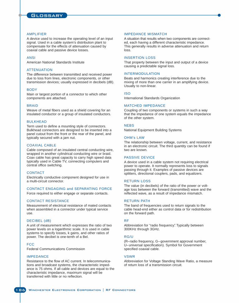
186 Winchester Electronics Corporation | RF Connectors
Glossary
AMPLIFIERA device used to increase the operating level of an inputsignal. Used in a cable system’s distribution plant to compensate for the effects of attenuation caused by coaxial cable and passive device losses.
ANSIAmerican National Standards Institute
ATTENUATIONThe difference between transmitted and received powerdue to loss from lines, electronic components, or othertransmission devices; usually expressed in decibels (dB).
BODYMain or largest portion of a connector to which othercomponents are attached.
BRAIDWeave of metal fibers used as a shield covering for aninsulated conductor or a group of insulated conductors.
BULKHEADTerm used to define a mounting style of connectors.Bulkhead connectors are designed to be inserted into apanel cutout from the front or the rear of the panel, andtypically secured with a jam nut.
COAXIAL CABLECable composed of an insulated central conducting wire,wrapped in another cylindrical conducting wire or braid.Coax cable has great capacity to carry high speed datatypically used in Cable TV, connecting computers and central office switching.
CONTACTElectrically conductive component designed for use in a multi-circuit connector.
CONTACT ENGAGING and SEPARATING FORCEForce required to either engage or separate contacts.
CONTACT RESISTANCEMeasurement of electrical resistance of mated contactswhen assembled in a connector under typical serviceuse.
DECIBEL (dB)A unit of measurement which expresses the ratio of twopower levels on a logarithmic scale. It is used in cablesystems to specify losses, k gains, and other ratios ofpower. The decibel is one-tenth of a Bel.
FCCFederal Communications Commission
IMPEDANCEResistance to the flow of AC current. In telecommunica-tions and broadcast systems, the characteristic imped-ance is 75 ohms. If all cable and devices are equal to the characteristic impedance, maximum signal will be transferred with little or no reflection.
IMPEDANCE MISMATCHA situation that results when two components are connect-ed, each having a different characteristic impedance.This generally results in adverse attenuation and returnloss.
INSERTION LOSSThat property between the input and output of a devicecausing a predictable signal loss.
INTERMODULATIONBeats and harmonics creating interference due to the mixing of more than one carrier in an amplifying device.Usually to non-linear.
ISOInternational Standards Organization
MATCHED IMPEDANCECoupling of two components or systems in such a waythat the impedance of one system equals the impedanceof the other system.
NEBSNational Equipment Building Systems
OHM’s LAWThe relationship between voltage, current, and resistancein an electronic circuit. The third quantity can be found iftwo are known.
PASSIVE DEVICEA device used in a cable system not requiring electricalpower to operate. It normally represents loss to signalspassing through it. Examples of passive devices are splitters, directional couplers, pads, and equalizers.
RETURN LOSSThe value (in decibels) of the ratio of the power or volt-age loss between the forward (transmitted) wave and thereflected wave, as a result of impedance mismatch.
RETURN PATHThe band of frequencies used to return signals to thecable head-end either as control data or for redistributionon the forward path.
RFAbbreviation for “radio frequency”. Typically between300KHz through 3GHz.
RG/U(R–radio frequency, G–government approval number,U–universal specification). Symbol for Government specified coaxial cable.
VSWRAbbreviation for Voltage Standing Wave Ratio, a measureof return loss of a transmission circuit.
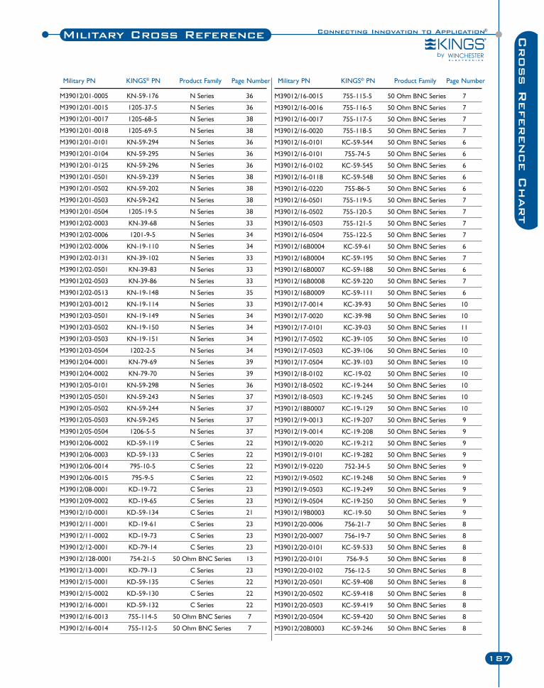
Connecting Innovation to Application®
187
Cross R
eference C
hart
Military Cross Reference
M39012/01-0005 KN-59-176 N Series 36
M39012/01-0015 1205-37-5 N Series 36
M39012/01-0017 1205-68-5 N Series 38
M39012/01-0018 1205-69-5 N Series 38
M39012/01-0101 KN-59-294 N Series 36
M39012/01-0104 KN-59-295 N Series 36
M39012/01-0125 KN-59-296 N Series 36
M39012/01-0501 KN-59-239 N Series 38
M39012/01-0502 KN-59-202 N Series 38
M39012/01-0503 KN-59-242 N Series 38
M39012/01-0504 1205-19-5 N Series 38
M39012/02-0003 KN-39-68 N Series 33
M39012/02-0006 1201-9-5 N Series 34
M39012/02-0006 KN-19-110 N Series 34
M39012/02-0131 KN-39-102 N Series 33
M39012/02-0501 KN-39-83 N Series 33
M39012/02-0503 KN-39-86 N Series 33
M39012/02-0513 KN-19-148 N Series 35
M39012/03-0012 KN-19-114 N Series 33
M39012/03-0501 KN-19-149 N Series 34
M39012/03-0502 KN-19-150 N Series 34
M39012/03-0503 KN-19-151 N Series 34
M39012/03-0504 1202-2-5 N Series 34
M39012/04-0001 KN-79-69 N Series 39
M39012/04-0002 KN-79-70 N Series 39
M39012/05-0101 KN-59-298 N Series 36
M39012/05-0501 KN-59-243 N Series 37
M39012/05-0502 KN-59-244 N Series 37
M39012/05-0503 KN-59-245 N Series 37
M39012/05-0504 1206-5-5 N Series 37
M39012/06-0002 KD-59-119 C Series 22
M39012/06-0003 KD-59-133 C Series 22
M39012/06-0014 795-10-5 C Series 22
M39012/06-0015 795-9-5 C Series 22
M39012/08-0001 KD-19-72 C Series 23
M39012/09-0002 KD-19-65 C Series 23
M39012/10-0001 KD-59-134 C Series 21
M39012/11-0001 KD-19-61 C Series 23
M39012/11-0002 KD-19-73 C Series 23
M39012/12-0001 KD-79-14 C Series 23
M39012/128-0001 754-21-5 50 Ohm BNC Series 13
M39012/13-0001 KD-79-13 C Series 23
M39012/15-0001 KD-59-135 C Series 22
M39012/15-0002 KD-59-130 C Series 22
M39012/16-0001 KD-59-132 C Series 22
M39012/16-0013 755-114-5 50 Ohm BNC Series 7
M39012/16-0014 755-112-5 50 Ohm BNC Series 7
Military PN KINGS® PN Product Family Page Number
M39012/16-0015 755-115-5 50 Ohm BNC Series 7
M39012/16-0016 755-116-5 50 Ohm BNC Series 7
M39012/16-0017 755-117-5 50 Ohm BNC Series 7
M39012/16-0020 755-118-5 50 Ohm BNC Series 7
M39012/16-0101 KC-59-544 50 Ohm BNC Series 6
M39012/16-0101 755-74-5 50 Ohm BNC Series 6
M39012/16-0102 KC-59-545 50 Ohm BNC Series 6
M39012/16-0118 KC-59-548 50 Ohm BNC Series 6
M39012/16-0220 755-86-5 50 Ohm BNC Series 6
M39012/16-0501 755-119-5 50 Ohm BNC Series 7
M39012/16-0502 755-120-5 50 Ohm BNC Series 7
M39012/16-0503 755-121-5 50 Ohm BNC Series 7
M39012/16-0504 755-122-5 50 Ohm BNC Series 7
M39012/16B0004 KC-59-61 50 Ohm BNC Series 6
M39012/16B0004 KC-59-195 50 Ohm BNC Series 7
M39012/16B0007 KC-59-188 50 Ohm BNC Series 6
M39012/16B0008 KC-59-220 50 Ohm BNC Series 7
M39012/16B0009 KC-59-111 50 Ohm BNC Series 6
M39012/17-0014 KC-39-93 50 Ohm BNC Series 10
M39012/17-0020 KC-39-98 50 Ohm BNC Series 10
M39012/17-0101 KC-39-03 50 Ohm BNC Series 11
M39012/17-0502 KC-39-105 50 Ohm BNC Series 10
M39012/17-0503 KC-39-106 50 Ohm BNC Series 10
M39012/17-0504 KC-39-103 50 Ohm BNC Series 10
M39012/18-0102 KC-19-02 50 Ohm BNC Series 10
M39012/18-0502 KC-19-244 50 Ohm BNC Series 10
M39012/18-0503 KC-19-245 50 Ohm BNC Series 10
M39012/18B0007 KC-19-129 50 Ohm BNC Series 10
M39012/19-0013 KC-19-207 50 Ohm BNC Series 9
M39012/19-0014 KC-19-208 50 Ohm BNC Series 9
M39012/19-0020 KC-19-212 50 Ohm BNC Series 9
M39012/19-0101 KC-19-282 50 Ohm BNC Series 9
M39012/19-0220 752-34-5 50 Ohm BNC Series 9
M39012/19-0502 KC-19-248 50 Ohm BNC Series 9
M39012/19-0503 KC-19-249 50 Ohm BNC Series 9
M39012/19-0504 KC-19-250 50 Ohm BNC Series 9
M39012/19B0003 KC-19-50 50 Ohm BNC Series 9
M39012/20-0006 756-21-7 50 Ohm BNC Series 8
M39012/20-0007 756-19-7 50 Ohm BNC Series 8
M39012/20-0101 KC-59-533 50 Ohm BNC Series 8
M39012/20-0101 756-9-5 50 Ohm BNC Series 8
M39012/20-0102 756-12-5 50 Ohm BNC Series 8
M39012/20-0501 KC-59-408 50 Ohm BNC Series 8
M39012/20-0502 KC-59-418 50 Ohm BNC Series 8
M39012/20-0503 KC-59-419 50 Ohm BNC Series 8
M39012/20-0504 KC-59-420 50 Ohm BNC Series 8
M39012/20B0003 KC-59-246 50 Ohm BNC Series 8
Military PN KINGS® PN Product Family Page Number

Military Cross Reference
188 Winchester Electronics Corporation | RF Connectors
M39012/21-0001 KC-79-105 50 Ohm BNC Series 13
M39012/21-0002 KC-79-106 50 Ohm BNC Series 13
M39012/22-0001 KC-79-109 50 Ohm BNC Series 12
M39012/23-0001 KC-79-110 50 Ohm BNC Series 13
M39012/23-0002 KC-79-111 50 Ohm BNC Series 13
M39012/24-0001 KC-79-107 50 Ohm BNC Series 13
M39012/24-0002 KC-79-108 50 Ohm BNC Series 13
M39012/25-0002 KD-89-08 C Series 21
M39012/25-0006 KC-89-87 50 Ohm BNC Series 11
M39012/25-0007 KC-89-88 50 Ohm BNC Series 11
M39012/25-0008 KC-89-89 50 Ohm BNC Series 11
M39012/25-0011 KN-89-30 N Series 41
M39012/25-0012 KN-89-31 N Series 41
M39012/25-0015 KC-89-92 50 Ohm BNC Series 11
M39012/25-0016 KC-89-93 50 Ohm BNC Series 11
M39012/25-0018 KA-81-02 TNC Series 80
M39012/25-0020 KA-81-01 TNC Series 80
M39012/25-0021 KA-89-82 TNC Series 80
M39012/25-0106 758-8-5 50 Ohm BNC Series 11
M39012/25-0118 128-26-5 TNC Series 80
M39012/25-0120 128-25-5 TNC Series 80
M39012/26-0010 KA-59-231 TNC Series 77
M39012/26-0011 KA-59-230 TNC Series 77
M39012/26-0012 KA-59-232 TNC Series 77
M39012/26-0013 KA-59-289 TNC Series 73
M39012/26-0021 KA-59-279 TNC Series 77
M39012/26-0022 125-19-5 TNC Series 77
M39012/26-0101 KA-59-22 TNC Series 73
M39012/26-0101 125-67-5 TNC Series 73
M39012/26-0102 KA-59-18 TNC Series 73
M39012/26-0501 KA-59-290 TNC Series 77
M39012/26-0502 KA-59-291 TNC Series 77
M39012/26-0503 KA-59-292 TNC Series 77
M39012/26-0504 KA-59-287 TNC Series 77
M39012/27-0101 KA-39-87 TNC Series 67
M39012/27-0503 KA-39-79 TNC Series 67
M39012/27-0504 KA-39-76 TNC Series 67
M39012/28-0010 KA-19-101 TNC Series 68
M39012/28-0011 KA-19-102 TNC Series 68
M39012/28-0018 122-32-5 TNC Series 68
M39012/28-0018 KA-19-171 TNC Series 68
M39012/28-0021 KA-19-146 TNC Series 68
M39012/28-0022 122-3-5 TNC Series 68
M39012/28-0101 KA-19-19 TNC Series 68
M39012/28-0101 122-27-5 TNC Series 68
M39012/28-0102 KA-19-172 TNC Series 68
M39012/28-0502 KA-19-151 TNC Series 68
M39012/28-0503 KA-19-152 TNC Series 68
M39012/28-0504 KA-19-153 TNC Series 68
M39012/29-0014 KA-19-110 TNC Series 69
M39012/29-0018 KA-19-181 TNC Series 67
M39012/29-0022 KA-19-214 TNC Series 69
M39012/29-0101 KA-19-176 TNC Series 67
M39012/29-0502 KA-19-155 TNC Series 69
M39012/29-0503 KA-19-156 TNC Series 69
M39012/29-0504 KA-19-157 TNC Series 69
M39012/30-0010 KA-59-235 TNC Series 72
M39012/30-0011 KA-59-236 TNC Series 72
M39012/30-0012 KA-59-237 TNC Series 72
M39012/30-0022 126-8-5 TNC Series 72
M39012/30-0101 KA-59-343 TNC Series 73
M39012/30-0101 126-55-5 TNC Series 73
M39012/30-0102 126-54-5 TNC Series 73
M39012/30-0118 KA-59-348 TNC Series 73
M39012/30-0502 KA-59-295 TNC Series 72
M39012/30-0503 KA-59-296 TNC Series 72
M39012/30-0504 KA-59-297 TNC Series 72
M39012/31-0001 KA-71-02 TNC Series 78
M39012/31-0002 KA-71-08 TNC Series 78
M39012/32-0001 KA-79-39 TNC Series 78
M39012/34-0001 KA-71-03 TNC Series 78
M39012/34-0002 KA-71-04 TNC Series 78
M39012/55-3007 875-81-17 SMA Series 49
M39012/55-3009 875-82-17 SMA Series 49
M39012/55-3109 875-82-3 SMA Series 49
M39012/55-3130 875-86-3 SMA Series 49
M39012/55-3502 875-21-17 SMA Series 58
M39012/55-3602 875-21-3 SMA Series 58
M39012/55-4502 875-21-18 SMA Series 58
M39012/55B3112 875-9-3 SMA Series 58
M39012/55B3114 875-1-3 SMA Series 58
M39012/55B3116 875-3-3 SMA Series 58
M39012/56-3009 876-61-17 SMA Series 49
M39012/56-3030 876-62-17 SMA Series 49
M39012/56-3107 876-60-3 SMA Series 49
M39012/56-3130 876-62-3 SMA Series 49
M39012/56B3114 873-1-3 SMA Series 51
M39012/57-3502 873-18-3 SMA Series 51
M39012/57-4502 873-18 SMA Series 51
M39012/58B4012 871-13 SMA Series 51
M39012/61-3002 874-11-3 SMA Series 57
M39012/61-3002 874-2-3 SMA Series 57
M39012/61-4001 874-1 SMA Series 57
M39012/79-3008 875-70-17 SMA Series 49
Military PN KINGS® PN Product Family Page Number Military PN KINGS® PN Product Family Page Number
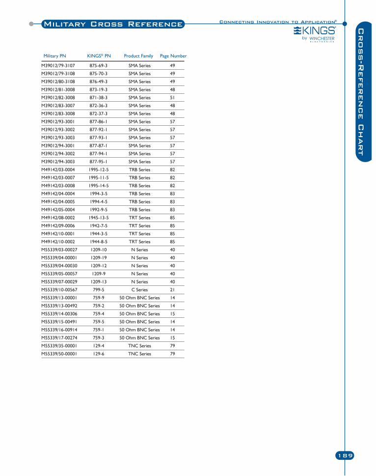
Connecting Innovation to Application®Military Cross Reference
189
Cross-R
eference C
hart
M39012/79-3107 875-69-3 SMA Series 49
M39012/79-3108 875-70-3 SMA Series 49
M39012/80-3108 876-49-3 SMA Series 49
M39012/81-3008 873-19-3 SMA Series 48
M39012/82-3008 871-38-3 SMA Series 51
M39012/83-3007 872-36-3 SMA Series 48
M39012/83-3008 872-37-3 SMA Series 48
M39012/93-3001 877-86-1 SMA Series 57
M39012/93-3002 877-92-1 SMA Series 57
M39012/93-3003 877-93-1 SMA Series 57
M39012/94-3001 877-87-1 SMA Series 57
M39012/94-3002 877-94-1 SMA Series 57
M39012/94-3003 877-95-1 SMA Series 57
M49142/03-0004 1995-12-5 TRB Series 82
M49142/03-0007 1995-11-5 TRB Series 82
M49142/03-0008 1995-14-5 TRB Series 82
M49142/04-0004 1994-3-5 TRB Series 83
M49142/04-0005 1994-4-5 TRB Series 83
M49142/05-0004 1992-9-5 TRB Series 83
M49142/08-0002 1945-13-5 TRT Series 85
M49142/09-0006 1942-7-5 TRT Series 85
M49142/10-0001 1944-3-5 TRT Series 85
M49142/10-0002 1944-8-5 TRT Series 85
M55339/03-00027 1209-10 N Series 40
M55339/04-00001 1209-19 N Series 40
M55339/04-00030 1209-12 N Series 40
M55339/05-00057 1209-9 N Series 40
M55339/07-00029 1209-13 N Series 40
M55339/10-00567 799-5 C Series 21
M55339/13-00001 759-9 50 Ohm BNC Series 14
M55339/13-00492 759-2 50 Ohm BNC Series 14
M55339/14-00306 759-4 50 Ohm BNC Series 15
M55339/15-00491 759-5 50 Ohm BNC Series 14
M55339/16-00914 759-1 50 Ohm BNC Series 14
M55339/17-00274 759-3 50 Ohm BNC Series 15
M55339/35-00001 129-4 TNC Series 79
M55339/50-00001 129-6 TNC Series 79
Military PN KINGS® PN Product Family Page Number
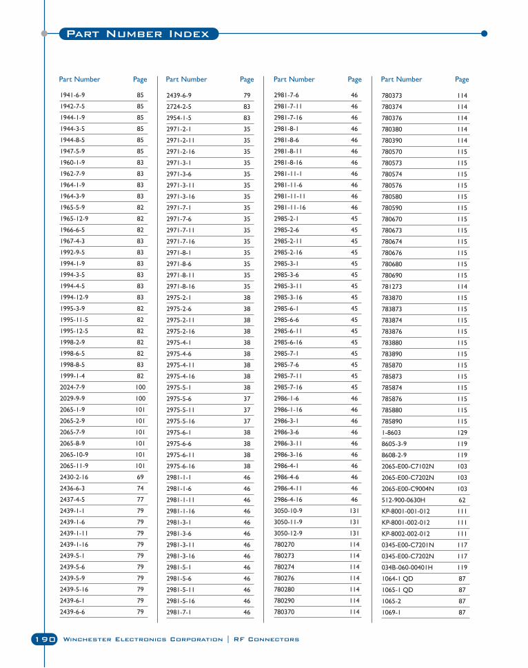
190 Winchester Electronics Corporation | RF Connectors
Part Number Index
1941-6-9 85
1942-7-5 85
1944-1-9 85
1944-3-5 85
1944-8-5 85
1947-5-9 85
1960-1-9 83
1962-7-9 83
1964-1-9 83
1964-3-9 83
1965-5-9 82
1965-12-9 82
1966-6-5 82
1967-4-3 83
1992-9-5 83
1994-1-9 83
1994-3-5 83
1994-4-5 83
1994-12-9 83
1995-3-9 82
1995-11-5 82
1995-12-5 82
1998-2-9 82
1998-6-5 82
1998-8-5 83
1999-1-4 82
2024-7-9 100
2029-9-9 100
2065-1-9 101
2065-2-9 101
2065-7-9 101
2065-8-9 101
2065-10-9 101
2065-11-9 101
2430-2-16 69
2436-6-3 74
2437-4-5 77
2439-1-1 79
2439-1-6 79
2439-1-11 79
2439-1-16 79
2439-5-1 79
2439-5-6 79
2439-5-9 79
2439-5-16 79
2439-6-1 79
2439-6-6 79
2439-6-9 79
2724-2-5 83
2954-1-5 83
2971-2-1 35
2971-2-11 35
2971-2-16 35
2971-3-1 35
2971-3-6 35
2971-3-11 35
2971-3-16 35
2971-7-1 35
2971-7-6 35
2971-7-11 35
2971-7-16 35
2971-8-1 35
2971-8-6 35
2971-8-11 35
2971-8-16 35
2975-2-1 38
2975-2-6 38
2975-2-11 38
2975-2-16 38
2975-4-1 38
2975-4-6 38
2975-4-11 38
2975-4-16 38
2975-5-1 38
2975-5-6 37
2975-5-11 37
2975-5-16 37
2975-6-1 38
2975-6-6 38
2975-6-11 38
2975-6-16 38
2981-1-1 46
2981-1-6 46
2981-1-11 46
2981-1-16 46
2981-3-1 46
2981-3-6 46
2981-3-11 46
2981-3-16 46
2981-5-1 46
2981-5-6 46
2981-5-11 46
2981-5-16 46
2981-7-1 46
2981-7-6 46
2981-7-11 46
2981-7-16 46
2981-8-1 46
2981-8-6 46
2981-8-11 46
2981-8-16 46
2981-11-1 46
2981-11-6 46
2981-11-11 46
2981-11-16 46
2985-2-1 45
2985-2-6 45
2985-2-11 45
2985-2-16 45
2985-3-1 45
2985-3-6 45
2985-3-11 45
2985-3-16 45
2985-6-1 45
2985-6-6 45
2985-6-11 45
2985-6-16 45
2985-7-1 45
2985-7-6 45
2985-7-11 45
2985-7-16 45
2986-1-6 46
2986-1-16 46
2986-3-1 46
2986-3-6 46
2986-3-11 46
2986-3-16 46
2986-4-1 46
2986-4-6 46
2986-4-11 46
2986-4-16 46
3050-10-9 131
3050-11-9 131
3050-12-9 131
780270 114
780273 114
780274 114
780276 114
780280 114
780290 114
780370 114
780373 114
780374 114
780376 114
780380 114
780390 114
780570 115
780573 115
780574 115
780576 115
780580 115
780590 115
780670 115
780673 115
780674 115
780676 115
780680 115
780690 115
781273 114
783870 115
783873 115
783874 115
783876 115
783880 115
783890 115
785870 115
785873 115
785874 115
785876 115
785880 115
785890 115
1-8603 129
8605-3-9 119
8608-2-9 119
2065-E00-C7102N 103
2065-E00-C7202N 103
2065-E00-C9004N 103
512-900-0630H 62
KP-8001-001-012 111
KP-8001-002-012 111
KP-8002-002-012 111
0345-E00-C7201N 117
0345-E00-C7202N 117
034B-060-00401H 119
1064-1 QD 87
1065-1 QD 87
1065-2 87
1069-1 87
Part Number Page Part Number Page Part Number Page Part Number Page
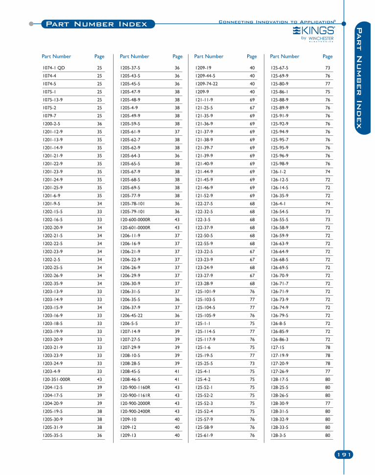
Connecting Innovation to Application®Part Number Index
191
Part N
umber In
dex
1074-1 QD 25
1074-4 25
1074-5 25
1075-1 25
1075-13-9 25
1075-2 25
1079-7 25
1200-2-5 36
1201-12-9 35
1201-13-9 35
1201-14-9 35
1201-21-9 35
1201-22-9 35
1201-23-9 35
1201-24-9 35
1201-25-9 35
1201-6-9 35
1201-9-5 34
1202-15-5 33
1202-16-5 33
1202-20-9 34
1202-21-5 34
1202-22-5 34
1202-23-9 34
1202-2-5 34
1202-25-5 34
1202-26-9 34
1202-35-9 34
1203-13-9 33
1203-14-9 33
1203-15-9 34
1203-16-9 33
1203-18-5 33
1203-19-9 33
1203-20-9 33
1203-21-9 33
1203-23-9 33
1203-24-9 33
1203-4-9 33
120-351-000R 43
1204-12-5 39
1204-17-5 39
1204-20-9 39
1205-19-5 38
1205-30-9 38
1205-31-9 38
1205-35-5 36
1205-37-5 36
1205-43-5 36
1205-45-5 36
1205-47-9 38
1205-48-9 38
1205-4-9 38
1205-49-9 38
1205-59-5 38
1205-61-9 37
1205-62-7 38
1205-62-9 38
1205-64-3 36
1205-65-5 38
1205-67-9 38
1205-68-5 38
1205-69-5 38
1205-77-9 38
1205-78-101 36
1205-79-101 36
120-600-0000R 43
120-601-0000R 43
1206-11-9 37
1206-16-9 37
1206-21-9 37
1206-22-9 37
1206-26-9 37
1206-29-9 37
1206-30-9 37
1206-31-5 37
1206-35-5 36
1206-37-9 37
1206-45-22 36
1206-5-5 37
1207-14-9 39
1207-27-5 39
1207-29-9 39
1208-10-5 39
1208-28-5 39
1208-45-5 41
1208-46-5 41
120-900-1160R 43
120-900-1161R 43
120-900-2000R 43
120-900-2400R 43
1209-10 40
1209-12 40
1209-13 40
1209-19 40
1209-44-5 40
1209-74-22 40
1209-9 40
121-11-9 69
121-25-5 67
121-35-9 69
121-36-9 69
121-37-9 69
121-38-9 69
121-39-7 69
121-39-9 69
121-40-9 69
121-44-9 69
121-45-9 69
121-46-9 69
121-52-9 69
122-27-5 68
122-32-5 68
122-3-5 68
122-37-9 68
122-50-5 68
122-55-9 68
123-22-5 67
123-23-9 67
123-24-9 68
123-27-9 67
123-28-9 68
125-101-9 76
125-103-5 77
125-104-5 77
125-105-9 76
125-1-1 75
125-114-5 77
125-117-9 76
125-1-6 75
125-19-5 77
125-25-5 73
125-4-1 75
125-4-2 75
125-52-1 75
125-52-2 75
125-52-3 75
125-52-4 75
125-57-9 76
125-58-9 76
125-61-9 76
125-67-5 73
125-69-9 76
125-80-9 77
125-86-1 75
125-88-9 76
125-89-9 76
125-91-9 76
125-92-9 76
125-94-9 76
125-95-7 76
125-95-9 76
125-96-9 76
125-98-9 76
126-1-2 74
126-12-5 72
126-14-5 72
126-35-9 72
126-4-1 74
126-54-5 73
126-55-5 73
126-58-9 72
126-59-9 72
126-63-9 72
126-64-9 72
126-68-5 72
126-69-5 72
126-70-9 72
126-71-7 72
126-71-9 72
126-73-9 72
126-74-9 72
126-79-5 72
126-8-5 72
126-85-9 72
126-86-3 72
127-15 78
127-19-9 78
127-20-9 78
127-26-9 77
128-17-5 80
128-25-5 80
128-26-5 80
128-30-9 77
128-31-5 80
128-32-9 80
128-33-5 80
128-3-5 80
Part Number Page Part Number Page Part Number Page Part Number Page
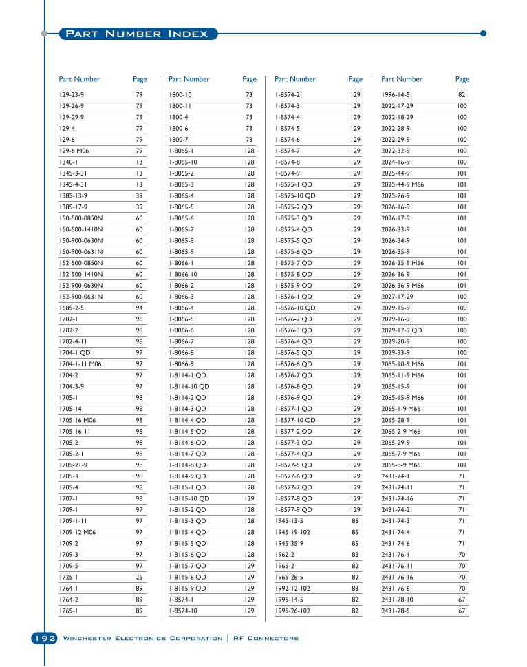
Part Number Index
192 Winchester Electronics Corporation | RF Connectors
129-23-9 79
129-26-9 79
129-29-9 79
129-4 79
129-6 79
129-6 M06 79
1340-1 13
1345-3-31 13
1345-4-31 13
1385-13-9 39
1385-17-9 39
150-500-0850N 60
150-500-1410N 60
150-900-0630N 60
150-900-0631N 60
152-500-0850N 60
152-500-1410N 60
152-900-0630N 60
152-900-0631N 60
1685-2-5 94
1702-1 98
1702-2 98
1702-4-11 98
1704-1 QD 97
1704-1-11 M06 97
1704-2 97
1704-3-9 97
1705-1 98
1705-14 98
1705-16 M06 98
1705-16-11 98
1705-2 98
1705-2-1 98
1705-21-9 98
1705-3 98
1705-4 98
1707-1 98
1709-1 97
1709-1-11 97
1709-12 M06 97
1709-2 97
1709-3 97
1709-5 97
1725-1 25
1764-1 89
1764-2 89
1765-1 89
1800-10 73
1800-11 73
1800-4 73
1800-6 73
1800-7 73
1-8065-1 128
1-8065-10 128
1-8065-2 128
1-8065-3 128
1-8065-4 128
1-8065-5 128
1-8065-6 128
1-8065-7 128
1-8065-8 128
1-8065-9 128
1-8066-1 128
1-8066-10 128
1-8066-2 128
1-8066-3 128
1-8066-4 128
1-8066-5 128
1-8066-6 128
1-8066-7 128
1-8066-8 128
1-8066-9 128
1-8114-1 QD 128
1-8114-10 QD 128
1-8114-2 QD 128
1-8114-3 QD 128
1-8114-4 QD 128
1-8114-5 QD 128
1-8114-6 QD 128
1-8114-7 QD 128
1-8114-8 QD 128
1-8114-9 QD 128
1-8115-1 QD 128
1-8115-10 QD 129
1-8115-2 QD 128
1-8115-3 QD 128
1-8115-4 QD 128
1-8115-5 QD 128
1-8115-6 QD 128
1-8115-7 QD 129
1-8115-8 QD 129
1-8115-9 QD 129
1-8574-1 129
1-8574-10 129
1-8574-2 129
1-8574-3 129
1-8574-4 129
1-8574-5 129
1-8574-6 129
1-8574-7 129
1-8574-8 129
1-8574-9 129
1-8575-1 QD 129
1-8575-10 QD 129
1-8575-2 QD 129
1-8575-3 QD 129
1-8575-4 QD 129
1-8575-5 QD 129
1-8575-6 QD 129
1-8575-7 QD 129
1-8575-8 QD 129
1-8575-9 QD 129
1-8576-1 QD 129
1-8576-10 QD 129
1-8576-2 QD 129
1-8576-3 QD 129
1-8576-4 QD 129
1-8576-5 QD 129
1-8576-6 QD 129
1-8576-7 QD 129
1-8576-8 QD 129
1-8576-9 QD 129
1-8577-1 QD 129
1-8577-10 QD 129
1-8577-2 QD 129
1-8577-3 QD 129
1-8577-4 QD 129
1-8577-5 QD 129
1-8577-6 QD 129
1-8577-7 QD 129
1-8577-8 QD 129
1-8577-9 QD 129
1945-13-5 85
1945-19-102 85
1945-35-9 85
1962-2 83
1965-2 82
1965-28-5 82
1992-12-102 83
1995-14-5 82
1995-26-102 82
1996-14-5 82
2022-17-29 100
2022-18-29 100
2022-28-9 100
2022-29-9 100
2022-32-9 100
2024-16-9 100
2025-44-9 101
2025-44-9 M66 101
2025-76-9 101
2026-16-9 101
2026-17-9 101
2026-33-9 101
2026-34-9 101
2026-35-9 101
2026-35-9 M66 101
2026-36-9 101
2026-36-9 M66 101
2027-17-29 100
2029-15-9 100
2029-16-9 100
2029-17-9 QD 100
2029-20-9 100
2029-33-9 100
2065-10-9 M66 101
2065-11-9 M66 101
2065-15-9 101
2065-15-9 M66 101
2065-1-9 M66 101
2065-28-9 101
2065-2-9 M66 101
2065-29-9 101
2065-7-9 M66 101
2065-8-9 M66 101
2431-74-1 71
2431-74-11 71
2431-74-16 71
2431-74-2 71
2431-74-3 71
2431-74-4 71
2431-74-6 71
2431-76-1 70
2431-76-11 70
2431-76-16 70
2431-76-6 70
2431-78-10 67
2431-78-5 67
Part Number Page Part Number Page Part Number Page Part Number Page
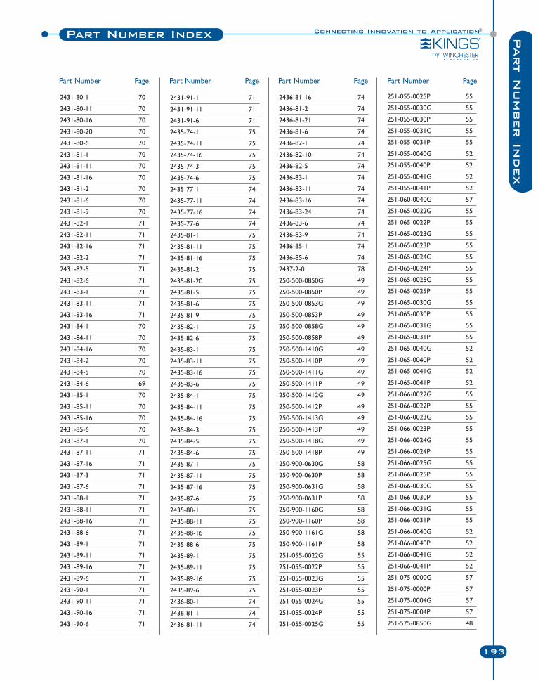
Connecting Innovation to Application®Part Number Index
193
Part N
umber In
dex
2431-80-1 70
2431-80-11 70
2431-80-16 70
2431-80-20 70
2431-80-6 70
2431-81-1 70
2431-81-11 70
2431-81-16 70
2431-81-2 70
2431-81-6 70
2431-81-9 70
2431-82-1 71
2431-82-11 71
2431-82-16 71
2431-82-2 71
2431-82-5 71
2431-82-6 71
2431-83-1 71
2431-83-11 71
2431-83-16 71
2431-84-1 70
2431-84-11 70
2431-84-16 70
2431-84-2 70
2431-84-5 70
2431-84-6 69
2431-85-1 70
2431-85-11 70
2431-85-16 70
2431-85-6 70
2431-87-1 70
2431-87-11 71
2431-87-16 71
2431-87-3 71
2431-87-6 71
2431-88-1 71
2431-88-11 71
2431-88-16 71
2431-88-6 71
2431-89-1 71
2431-89-11 71
2431-89-16 71
2431-89-6 71
2431-90-1 71
2431-90-11 71
2431-90-16 71
2431-90-6 71
2431-91-1 71
2431-91-11 71
2431-91-6 71
2435-74-1 75
2435-74-11 75
2435-74-16 75
2435-74-3 75
2435-74-6 75
2435-77-1 74
2435-77-11 74
2435-77-16 74
2435-77-6 74
2435-81-1 75
2435-81-11 75
2435-81-16 75
2435-81-2 75
2435-81-20 75
2435-81-5 75
2435-81-6 75
2435-81-9 75
2435-82-1 75
2435-82-6 75
2435-83-1 75
2435-83-11 75
2435-83-16 75
2435-83-6 75
2435-84-1 75
2435-84-11 75
2435-84-16 75
2435-84-3 75
2435-84-5 75
2435-84-6 75
2435-87-1 75
2435-87-11 75
2435-87-16 75
2435-87-6 75
2435-88-1 75
2435-88-11 75
2435-88-16 75
2435-88-6 75
2435-89-1 75
2435-89-11 75
2435-89-16 75
2435-89-6 75
2436-80-1 74
2436-81-1 74
2436-81-11 74
2436-81-16 74
2436-81-2 74
2436-81-21 74
2436-81-6 74
2436-82-1 74
2436-82-10 74
2436-82-5 74
2436-83-1 74
2436-83-11 74
2436-83-16 74
2436-83-24 74
2436-83-6 74
2436-83-9 74
2436-85-1 74
2436-85-6 74
2437-2-0 78
250-500-0850G 49
250-500-0850P 49
250-500-0853G 49
250-500-0853P 49
250-500-0858G 49
250-500-0858P 49
250-500-1410G 49
250-500-1410P 49
250-500-1411G 49
250-500-1411P 49
250-500-1412G 49
250-500-1412P 49
250-500-1413G 49
250-500-1413P 49
250-500-1418G 49
250-500-1418P 49
250-900-0630G 58
250-900-0630P 58
250-900-0631G 58
250-900-0631P 58
250-900-1160G 58
250-900-1160P 58
250-900-1161G 58
250-900-1161P 58
251-055-0022G 55
251-055-0022P 55
251-055-0023G 55
251-055-0023P 55
251-055-0024G 55
251-055-0024P 55
251-055-0025G 55
251-055-0025P 55
251-055-0030G 55
251-055-0030P 55
251-055-0031G 55
251-055-0031P 55
251-055-0040G 52
251-055-0040P 52
251-055-0041G 52
251-055-0041P 52
251-060-0040G 57
251-065-0022G 55
251-065-0022P 55
251-065-0023G 55
251-065-0023P 55
251-065-0024G 55
251-065-0024P 55
251-065-0025G 55
251-065-0025P 55
251-065-0030G 55
251-065-0030P 55
251-065-0031G 55
251-065-0031P 55
251-065-0040G 52
251-065-0040P 52
251-065-0041G 52
251-065-0041P 52
251-066-0022G 55
251-066-0022P 55
251-066-0023G 55
251-066-0023P 55
251-066-0024G 55
251-066-0024P 55
251-066-0025G 55
251-066-0025P 55
251-066-0030G 55
251-066-0030P 55
251-066-0031G 55
251-066-0031P 55
251-066-0040G 52
251-066-0040P 52
251-066-0041G 52
251-066-0041P 52
251-075-0000G 57
251-075-0000P 57
251-075-0004G 57
251-075-0004P 57
251-575-0850G 48
Part Number Page Part Number Page Part Number Page Part Number Page
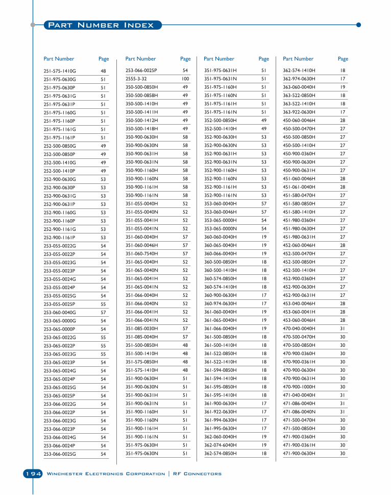
Part Number Index
194 Winchester Electronics Corporation | RF Connectors
251-575-1410G 48
251-975-0630G 51
251-975-0630P 51
251-975-0631G 51
251-975-0631P 51
251-975-1160G 51
251-975-1160P 51
251-975-1161G 51
251-975-1161P 51
252-500-0850G 49
252-500-0850P 49
252-500-1410G 49
252-500-1410P 49
252-900-0630G 53
252-900-0630P 53
252-900-0631G 53
252-900-0631P 53
252-900-1160G 53
252-900-1160P 53
252-900-1161G 53
252-900-1161P 53
253-055-0022G 54
253-055-0022P 54
253-055-0023G 54
253-055-0023P 54
253-055-0024G 54
253-055-0024P 54
253-055-0025G 54
253-055-0025P 55
253-060-0040G 57
253-065-0000G 54
253-065-0000P 54
253-065-0022G 55
253-065-0022P 55
253-065-0023G 55
253-065-0023P 54
253-065-0024G 54
253-065-0024P 54
253-065-0025G 54
253-065-0025P 54
253-066-0022G 54
253-066-0022P 54
253-066-0023G 54
253-066-0023P 54
253-066-0024G 54
253-066-0024P 54
253-066-0025G 54
253-066-0025P 54
2555-3-32 100
350-500-0850H 49
350-500-0858H 49
350-500-1410H 49
350-500-1411H 49
350-500-1412H 49
350-500-1418H 49
350-900-0630H 58
350-900-0630N 58
350-900-0631H 58
350-900-0631N 58
350-900-1160H 58
350-900-1160N 58
350-900-1161H 58
350-900-1161N 58
351-055-0040H 52
351-055-0040N 52
351-055-0041H 52
351-055-0041N 52
351-060-0040H 57
351-060-0046H 57
351-060-7540H 57
351-065-0040H 52
351-065-0040N 52
351-065-0041H 52
351-065-0041N 52
351-066-0040H 52
351-066-0040N 52
351-066-0041H 52
351-066-0041N 52
351-085-0030H 57
351-085-0040H 57
351-500-0850H 48
351-500-1410H 48
351-575-0850H 48
351-575-1410H 48
351-900-0630H 51
351-900-0630N 51
351-900-0631H 51
351-900-0631N 51
351-900-1160H 51
351-900-1160N 51
351-900-1161H 51
351-900-1161N 51
351-975-0630H 51
351-975-0630N 51
351-975-0631H 51
351-975-0631N 51
351-975-1160H 51
351-975-1160N 51
351-975-1161H 51
351-975-1161N 51
352-500-0850H 49
352-500-1410H 49
352-900-0630H 53
352-900-0630N 53
352-900-0631H 53
352-900-0631N 53
352-900-1160H 53
352-900-1160N 53
352-900-1161H 53
352-900-1161N 53
353-060-0040H 57
353-060-0046H 57
353-065-0000H 54
353-065-0000N 54
360-060-0040H 19
360-065-0040H 19
360-066-0040H 19
360-500-0850H 18
360-500-1410H 18
360-574-0850H 18
360-574-1410H 18
360-900-0630H 17
360-974-0630H 17
361-060-0040H 19
361-065-0040H 19
361-066-0040H 19
361-500-0850H 18
361-500-1410H 18
361-522-0850H 18
361-522-1410H 18
361-594-0850H 18
361-594-1410H 18
361-595-0850H 18
361-595-1410H 18
361-900-0630H 17
361-922-0630H 17
361-994-0630H 17
361-995-0630H 17
362-060-0040H 19
362-074-6040H 19
362-574-0850H 18
362-574-1410H 18
362-974-0630H 17
363-060-0040H 19
363-522-0850H 18
363-522-1410H 18
363-922-0630H 17
450-060-0046H 28
450-500-0470H 27
450-500-0850H 27
450-500-1410H 27
450-900-0360H 27
450-900-0630H 27
450-900-0631H 27
451-060-0046H 28
451-061-0040H 28
451-580-0470H 27
451-580-0850H 27
451-580-1410H 27
451-980-0360H 27
451-980-0630H 27
451-980-0631H 27
452-060-0046H 28
452-500-0470H 27
452-500-0850H 27
452-500-1410H 27
452-900-0360H 27
452-900-0630H 27
452-900-0631H 27
453-040-0046H 28
453-060-0041H 28
453-060-0046H 28
470-040-0040H 31
470-500-0470H 30
470-500-0850H 30
470-900-0360H 30
470-900-0361H 30
470-900-0630H 30
470-900-0631H 30
470-900-1000H 30
471-040-0040H 31
471-086-0040H 31
471-086-0040N 31
471-500-0470H 30
471-500-0850H 30
471-900-0360H 30
471-900-0361H 30
471-900-0630H 30
Part Number Page Part Number Page Part Number Page Part Number Page
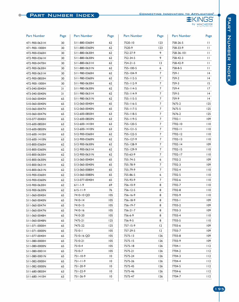
Connecting Innovation to Application®Part Number Index
195
Part N
umber In
dex
471-900-0631H 30
471-900-1000H 30
472-900-0360H 30
472-900-0361H 30
472-900-0470H 30
472-900-0630H 30
472-900-0631H 30
472-900-0850H 30
472-900-1000H 30
473-040-0040H 31
473-040-0040N 31
510-060-0040H 65
510-060-0040N 65
510-060-0047H 65
510-060-0047N 65
510-077-0040H 65
510-600-0850H 63
510-600-0850N 63
510-600-1410H 63
510-600-1410N 63
510-800-0360H 62
510-800-0360N 62
510-800-0630H 62
510-800-0630N 62
510-800-0631H 62
510-800-0631N 62
510-900-0360H 62
510-900-0360N 62
510-900-0630H 62
510-900-0630N 62
511-060-0040H 65
511-060-0040N 65
511-060-0047H 65
511-060-0047N 65
511-060-0048H 65
511-060-0048N 65
511-071-0000H 65
511-071-0000N 65
511-077-0040H 65
511-080-0000H 65
511-080-0000N 65
511-080-0001H 65
511-080-0001N 65
511-082-0000H 65
511-082-0000N 65
511-680-0850H 63
511-680-1410H 63
511-880-0360H 62
511-880-0360N 62
511-880-0630H 62
511-880-0630N 62
511-880-0631H 62
511-880-0631N 62
511-980-0360H 62
511-980-0360N 62
511-980-0630H 62
511-980-0630N 62
511-980-0631H 62
511-980-0631N 62
512-060-0040H 65
512-060-0040N 65
512-600-0850H 63
512-600-0850N 63
512-600-1410H 63
512-600-1410N 63
512-900-0360H 62
512-900-0360N 62
512-900-0630N 62
512-900-0631H 62
512-900-0631N 62
513-060-0040H 65
513-060-0040N 65
513-060-0080H 65
513-060-0080N 65
513-077-0040H 65
611-1-9 69
615-11-9 76
7410-10 QD 105
7410-14 105
7410-15 105
7410-16 105
7410-20 105
7475-21 125
7475-22 125
7510-1 105
7510-16 QD 105
7510-21 105
7510-4 105
7510-7 105
751-10-9 10
751-11-9 10
751-20-9 10
751-22-9 10
751-26-9 10
7520-10 123
7520-9 123
752-27-9 9
752-34-5 9
754-21-5 13
755-100-5 6
755-104-9 7
755-112-5 7
755-112-9 7
755-114-5 7
755-114-9 7
755-115-5 7
755-116-5 7
755-117-5 7
755-118-5 7
755-119-5 7
755-120-5 7
755-121-5 7
755-122-5 7
755-127-9 7
755-128-9 7
755-129-9 7
755-63-9 7
755-74-5 6
755-78-9 7
755-79-9 7
755-86-5 6
755-93-9 7
756-10-9 8
756-12-5 8
756-16-9 8
756-18-9 8
756-19-7 8
756-21-7 8
756-6-9 8
756-9-5 8
757-15-9 12
757-29-5 12
7575-13 126
7575-15 126
7575-18 126
7575-21 126
7575-24 126
7575-26 126
7575-45 126
7575-46 126
7575-47 126
758-26-5 11
758-33-9 11
758-36-101 11
758-42-3 11
758-42-9 11
758-8-5 11
759-1 14
759-2 14
759-3 15
759-4 17
759-5 14
759-9 14
7675-2 125
7675-5 125
7676-2 125
7702-1 109
7702-10 110
7702-11 110
7702-12 110
7702-13 110
7702-14 109
7702-15 110
7702-17 110
7702-2 109
7702-3 109
7702-4 110
7702-5 110
7702-6 110
7702-7 110
7702-8 110
7702-9 110
7703-1 109
7703-2 109
7703-3 109
7703-4 110
7703-5 110
7703-6 109
7703-7 109
7703-8 109
7703-9 109
7704-1 112
7704-2 112
7704-3 112
7704-4 112
7704-5 112
7704-6 112
7704-7 112
Part Number Page Part Number Page Part Number Page Part Number Page
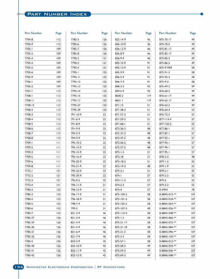
Part Number Index
196 Winchester Electronics Corporation | RF Connectors
7704-8 112
7704-9 112
7705-1 109
7705-2 109
7705-3 109
7705-4 109
7705-5 109
7705-6 109
7705-9 109
7706-1 109
7706-2 109
7707-1 112
7708-1 112
7708-11 112
7708-12 112
7708-2 112
7708-3 112
7708-4 112
7708-5 112
7708-6 112
7708-7 112
7708-8 112
7709-1 111
7709-2 111
7709-3 111
7709-5 111
7709-6 111
7709-8 111
7772-1 121
7772-2 121
7772-3 121
7772-4 121
7780-2 123
7780-3 123
7780-4 123
7780-5 123
7780-6 123
7780-7 123
7785-27 126
7785-29 126
7785-30 126
7785-31 126
7785-32 126
7785-4 126
7785-40 126
7785-41 126
7785-42 126
7785-5 126
7785-6 126
7785-7 126
7785-8 126
7790-2 121
7790-3 121
7790-4 121
7795-1 125
7795-11 125
7795-12 125
7795-13 125
7795-14 125
7795-15 125
7795-17 125
7795-27 125
7795-29 125
791-10-9 23
791-6-9 23
791-8-9 23
791-9-9 23
794-3-9 23
794-4-9 23
795-10-5 22
795-13-9 22
795-15-9 22
795-16-9 22
795-20-9 22
795-21-9 22
795-23-9 22
795-30-9 22
795-9-5 22
796-11-9 21
796-15-9 21
796-17-9 21
796-18-9 21
798-7-9 21
799-5 21
821-2-9 46
821-3-9 46
821-4-9 46
821-5-9 46
821-6-9 46
821-7-9 46
823-2-9 45
825-10-9 45
825-11-9 45
825-12-9 45
825-14-9 45
826-10-9 46
826-12-9 46
826-8-9 46
826-9-9 46
845-10-9 91
845-13-9 91
845-9-9 91
846-5-9 91
846-7-9 91
848-3-5 92
849-5-9 92
8600-2 119
8601-1 119
871-13 51
871-38-3 51
871-57-3 51
871-59-3 51
871-68-1 51
872-36-3 48
872-37-3 48
872-47-3 48
872-56-2 48
872-57-3 48
873-1-3 51
873-18 51
873-18-3 51
873-19-3 48
873-3-1 51
874-1 57
874-11-3 57
874-2-3 57
874-4 57
875-100-3 58
875-101-3 58
875-105-3 58
875-107-3 49
875-110-4 58
875-1-3 58
875-21-17 58
875-21-18 58
875-21-3 58
875-3-3 58
875-57-1 58
875-58-3 49
875-59-3 49
875-69-3 49
875-70-17 49
875-70-3 49
875-81-17 49
875-82-17 49
875-82-3 49
875-86-3 49
875-9 M09 58
875-91-3 58
875-92-3 58
875-9-3 58
876-49-3 49
876-60-3 49
876-61-17 49
876-62-17 49
876-62-3 49
876-64-3 53
876-72-3 53
877-114-4 57
877-120-5 55
877-86-1 57
877-87-1 57
877-92-1 57
877-93-1 57
877-94-1 57
877-95-1 57
878-2-3 48
879-1-3 55
879-1-9 55
879-2-1 55
879-2-3 55
879-3 55
879-3-3 55
K-4944 78
K-8845-012-** 107
K-8845-018-** 107
K-8845-024-** 107
K-8845-036-** 107
K-8845-048-** 107
K-8845-060-** 107
K-8845-072-** 107
K-8845-084-** 107
K-8845-096-** 107
K-8845-120-** 107
K-8846-012-** 107
K-8846-024-** 107
K-8846-036-** 107
K-8846-048-** 107
Part Number Page Part Number Page Part Number Page Part Number Page
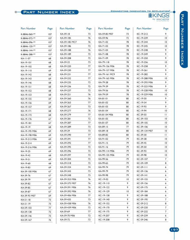
Connecting Innovation to Application®Part Number Index
197
Part N
umber In
dex
K-8846-060-** 107
K-8846-072-** 107
K-8846-096-** 107
K-8846-120-** 107
K-8846-144-** 107
K-8846-288-** 107
KA-11-07 68
KA-19-101 68
KA-19-102 68
KA-19-110 69
KA-19-142 68
KA-19-143 69
KA-19-146 68
KA-19-151 68
KA-19-152 68
KA-19-153 68
KA-19-155 69
KA-19-156 69
KA-19-157 69
KA-19-171 68
KA-19-172 68
KA-19-176 67
KA-19-181 67
KA-19-19 68
KA-19-195 M06 69
KA-19-198 M06 69
KA-19-213 M06 69
KA-19-214 69
KA-19-216 M06 69
KA-19-25 69
KA-19-42 68
KA-19-51 69
KA-19-60 68
KA-19-83 69
KA-39-100 M06 67
KA-39-76 67
KA-39-79 67
KA-39-82 67
KA-39-85 67
KA-39-87 67
KA-39-93 M07 69
KA-51-18 73
KA-51-19 73
KA-59-103 77
KA-59-138 72
KA-59-146 73
KA-59-167 76
KA-59-18 73
KA-59-185 76
KA-59-185 MC7 76
KA-59-186 72
KA-59-188 76
KA-59-189 72
KA-59-208 72
KA-59-22 73
KA-59-220 77
KA-59-230 77
KA-59-231 77
KA-59-232 77
KA-59-235 72
KA-59-236 72
KA-59-237 72
KA-59-251 76
KA-59-260 76
KA-59-263 77
KA-59-267 73
KA-59-277 76
KA-59-279 77
KA-59-281 72
KA-59-287 77
KA-59-289 73
KA-59-29 73
KA-59-290 77
KA-59-291 77
KA-59-292 77
KA-59-295 72
KA-59-296 72
KA-59-297 72
KA-59-304 72
KA-59-318 72
KA-59-324 74
KA-59-343 73
KA-59-348 73
KA-59-353 M06 76
KA-59-375 M07 76
KA-59-391 M06 76
KA-59-392 M06 76
KA-59-406 M06 77
KA-59-435 73
KA-59-438 M06 76
KA-59-439 M06 72
KA-59-69 77
KA-59-70 M06 72
KA-59-72 72
KA-59-85 M07 73
KA-59-96 72
KA-71-02 78
KA-71-03 78
KA-71-04 78
KA-71-08 78
KA-71-09 78
KA-79-118 78
KA-79-156 M06 78
KA-79-157 M06 78
KA-79-161 MC9 78
KA-79-165 M06 78
KA-79-28 78
KA-79-39 78
KA-79-56 78
KA-79-59 78
KA-81-01 80
KA-81-02 80
KA-81-03 80
KA-81-04 80
KA-81-04 M06 80
KA-81-05 80
KA-81-07 80
KA-89-15 77
KA-89-18 80
KA-89-82 80
KA-91-02 79
KA-91-15 79
KA-91-16 79
KA-99-114 M06 79
KA-99-125 M06 79
KA-99-56 79
KA-99-65 79
KA-99-74 79
KA-99-79 79
KA-99-98 79
KC-19-02 10
KC-19-110 9
KC-19-122 9
KC-19-129 10
KC-19-138 9
KC-19-140 9
KC-19-152 9
KC-19-170 9
KC-19-175 9
KC-19-207 9
KC-19-208 9
KC-19-212 9
KC-19-239 10
KC-19-244 10
KC-19-245 10
KC-19-248 9
KC-19-249 9
KC-19-250 9
KC-19-256 10
KC-19-258 9
KC-19-261 9
KC-19-282 9
KC-19-288 M06 10
KC-19-293 M06 9
KC-19-323 M06 9
KC-19-328 M06 10
KC-19-329 M06 10
KC-19-50 9
KC-19-54 9
KC-19-93 9
KC-19-94 10
KC-39-03 11
KC-39-103 10
KC-39-105 10
KC-39-106 10
KC-39-134 M07 10
KC-39-30 11
KC-39-38 10
KC-39-45 10
KC-39-50 10
KC-39-93 10
KC-39-98 10
KC-59-107 7
KC-59-109 8
KC-59-111 6
KC-59-136 6
KC-59-141 6
KC-59-155 6
KC-59-156 6
KC-59-175 6
KC-59-184 6
KC-59-188 6
KC-59-195 7
KC-59-212 8
KC-59-220 7
KC-59-232 7
KC-59-239 6
KC-59-246 8
Part Number Page Part Number Page Part Number Page Part Number Page
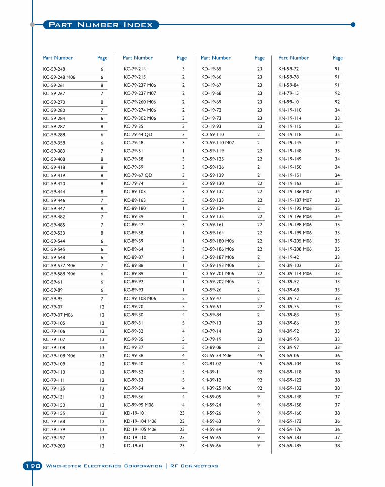
Part Number Index
198 Winchester Electronics Corporation | RF Connectors
KC-59-248 6
KC-59-248 M06 6
KC-59-261 8
KC-59-267 7
KC-59-270 8
KC-59-280 7
KC-59-284 6
KC-59-287 8
KC-59-288 6
KC-59-358 6
KC-59-383 7
KC-59-408 8
KC-59-418 8
KC-59-419 8
KC-59-420 8
KC-59-444 8
KC-59-446 7
KC-59-447 8
KC-59-482 7
KC-59-485 7
KC-59-533 8
KC-59-544 6
KC-59-545 6
KC-59-548 6
KC-59-577 M06 7
KC-59-588 M06 6
KC-59-61 6
KC-59-89 6
KC-59-95 7
KC-79-07 12
KC-79-07 M06 12
KC-79-105 13
KC-79-106 13
KC-79-107 13
KC-79-108 13
KC-79-108 M06 13
KC-79-109 12
KC-79-110 13
KC-79-111 13
KC-79-125 12
KC-79-131 13
KC-79-150 13
KC-79-155 13
KC-79-168 12
KC-79-179 13
KC-79-197 13
KC-79-200 13
KC-79-214 13
KC-79-215 12
KC-79-237 M06 12
KC-79-237 M07 12
KC-79-260 M06 12
KC-79-274 M06 12
KC-79-302 M06 13
KC-79-35 13
KC-79-44 QD 13
KC-79-48 13
KC-79-51 11
KC-79-58 13
KC-79-59 13
KC-79-67 QD 13
KC-79-74 13
KC-89-103 13
KC-89-163 13
KC-89-180 11
KC-89-39 11
KC-89-42 13
KC-89-58 11
KC-89-59 11
KC-89-64 13
KC-89-87 11
KC-89-88 11
KC-89-89 11
KC-89-92 11
KC-89-93 11
KC-99-108 M06 15
KC-99-20 15
KC-99-30 14
KC-99-31 15
KC-99-32 14
KC-99-35 15
KC-99-37 15
KC-99-38 14
KC-99-40 14
KC-99-52 15
KC-99-53 15
KC-99-54 14
KC-99-56 14
KC-99-95 M06 14
KD-19-101 23
KD-19-104 M06 23
KD-19-105 M06 23
KD-19-110 23
KD-19-61 23
KD-19-65 23
KD-19-66 23
KD-19-67 23
KD-19-68 23
KD-19-69 23
KD-19-72 23
KD-19-73 23
KD-19-93 23
KD-59-110 21
KD-59-110 M07 21
KD-59-119 22
KD-59-125 22
KD-59-126 21
KD-59-129 21
KD-59-130 22
KD-59-132 22
KD-59-133 22
KD-59-134 21
KD-59-135 22
KD-59-161 22
KD-59-164 22
KD-59-180 M06 22
KD-59-186 M06 22
KD-59-187 M06 21
KD-59-193 M06 21
KD-59-201 M06 22
KD-59-202 M06 21
KD-59-26 21
KD-59-47 21
KD-59-63 22
KD-59-84 21
KD-79-13 23
KD-79-14 23
KD-79-19 23
KD-89-08 21
KG-59-34 M06 45
KG-81-02 45
KH-39-11 92
KH-39-12 92
KH-39-25 M06 92
KH-59-05 91
KH-59-24 91
KH-59-26 91
KH-59-63 91
KH-59-64 91
KH-59-65 91
KH-59-66 91
KH-59-72 91
KH-59-78 91
KH-59-84 91
KH-79-15 92
KH-99-10 92
KN-19-110 34
KN-19-114 33
KN-19-115 35
KN-19-118 35
KN-19-145 34
KN-19-148 35
KN-19-149 34
KN-19-150 34
KN-19-151 34
KN-19-162 35
KN-19-186 M07 34
KN-19-187 M07 33
KN-19-195 M06 35
KN-19-196 M06 34
KN-19-198 M06 35
KN-19-199 M06 35
KN-19-205 M06 35
KN-19-208 M06 35
KN-19-42 33
KN-39-102 33
KN-39-114 M06 33
KN-39-52 33
KN-39-68 33
KN-39-72 33
KN-39-75 33
KN-39-83 33
KN-39-86 33
KN-39-92 33
KN-39-93 33
KN-39-97 33
KN-59-06 36
KN-59-104 38
KN-59-118 38
KN-59-122 38
KN-59-132 38
KN-59-148 37
KN-59-158 37
KN-59-160 38
KN-59-173 36
KN-59-176 36
KN-59-183 37
KN-59-185 38
Part Number Page Part Number Page Part Number Page Part Number Page
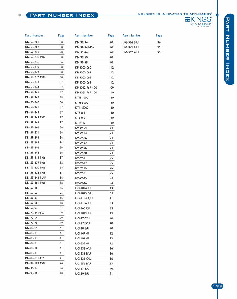
Connecting Innovation to Application®Part Number Index
199
Part N
umber In
dex
KN-59-201 38
KN-59-202 38
KN-59-220 38
KN-59-220 M07 38
KN-59-226 36
KN-59-239 38
KN-59-242 38
KN-59-242 M06 38
KN-59-243 37
KN-59-244 37
KN-59-245 37
KN-59-247 38
KN-59-260 38
KN-59-261 37
KN-59-263 37
KN-59-263 M07 37
KN-59-264 37
KN-59-266 38
KN-59-271 36
KN-59-294 36
KN-59-295 36
KN-59-296 36
KN-59-298 36
KN-59-313 M06 37
KN-59-329 M06 38
KN-59-330 M06 38
KN-59-332 M06 37
KN-59-344 MAF 36
KN-59-361 M06 38
KN-59-48 36
KN-59-53 36
KN-59-57 36
KN-59-68 38
KN-59-92 37
KN-79-45 M06 39
KN-79-69 39
KN-79-70 39
KN-89-05 41
KN-89-12 41
KN-89-13 41
KN-89-14 41
KN-89-30 41
KN-89-31 41
KN-89-87 M07 41
KN-99-102 M06 40
KN-99-14 40
KN-99-30 40
Part Number Page
KN-99-34 40
KN-99-34 M06 40
KN-99-44 40
KN-99-50 40
KN-99-58 40
KP-8000-060 112
KP-8000-061 112
KP-8000-062 112
KP-8000-063 112
KP-8012-767-400 109
KP-8021-767-400 110
KTH-1000 130
KTH-5000 130
KTM-5000 130
KTS-8-1 130
KTS-8-2 130
KTW-13 130
KV-59-04 94
KV-59-23 94
KV-59-26 94
KV-59-37 94
KV-59-56 94
KV-59-70 94
KV-79-11 95
KV-79-12 95
KV-79-15 95
KV-79-21 95
KV-99-45 94
KV-99-46 94
UG-1094 /U 13
UG-1095 B/U 34
UG-1104 A/U 11
UG-1186 /U 33
UG-160 C/U 33
UG-1873 /U 13
UG-27 C/U 40
UG-27 D/U 40
UG-30 E/U 40
UG-447 /U 12
UG-496 /U 92
UG-535 /U 12
UG-536 A/U 36
UG-536 B/U 36
UG-536 C/U 36
UG-556 B/U 33
UG-57 B/U 40
UG-59 E/U 91
UG-594 B/U 36
UG-943 B/U 22
UG-997 A/U 39
Part Number Page Part Number Page

200 Winchester Electronics Corporation | RF Connectors
Notes

All Winchester Electronics KINGS® brand products
are manufactured under ISO 9001-2000 and
AS9100 registered quality management systems.
All Winchester Electronics KINGS® brand products are in full compliance
with the European Union Directive 2002/95/EC (RoHS). We are committed
to continuous improvement, and are actively working to ensure restricted
substances are removed from our products, or below RoHS specified limits.
Winchester Electronics KINGS® brand RF connector
and patch plug products are Network Equipment–
Building Systems (NEBS) Level III Certified.
Registered Trademarks of Winchester Electronics Corporation -TR-4®, TR-5®, K-GRIP®, K-GRIP JR®, WEATHERPROOF K-GRIP JR®, PRE-ASSEMBLED K-GRIP®, TAPERGRIP®, SPEED-GRIP®, TRI-LOC®, ROTO-STRIP®, the KINGS SYMBOL, and Connecting Innovation toApplication® KINGS and the KINGS DESIGN are trademarks of Winchester Electronics Corporation.
While the information in this publication is believed to be accurate and reliable, all data presentedis subject to change without notice. Winchester Electronics Corporation disclaims responsibility forany damages resulting from application or any incompleteness or inaccuracies in the informationpresented. Consult factory for specific information on the latest design specifications.

©2009 Winchester Electronics Corporation. All rights reserved. Literature Item #CAT-RF-CONN SOL
NORTH AMERICA
UNITED STATESWinchester Electronics CorporationWorld Headquarters
62 Barnes Industrial Road NorthWallingford, Connecticut 06492Phone: 203-741-5400Fax: 203-741-5500
Winchester Electronics101 Constitution Boulevard, Suite BFranklin, Massachusetts 02038Phone: 203-741-2400Fax: 203-741-5500
Winchester Electronics3049 SouthCross Boulevard, Suite 101Rock Hill, South Carolina 29730Phone: 803-909-5000Fax: 203-741-5500
MEXICOWinchester ElectronicsCarretera Int’l Km. 7.5Parque Industrial “El Cid”Nogales, SonoraMexicoPhone: 203-741-5570Fax: 203-741-5500
ASIA
JAPANWinchester Electronics Corporation– JapanRM #201, Klingelnberg Building1-13-12, Shin Yokohama Kohoku-KuYokohama, Kanagawa 222-0033 JapanPhone: 81-45-477-5115Fax: 81-45-475-3200
CHINAWinchester Electronics (Suzhou) Co., LTDNo. 18 QunXing First StreetSIP, Suzhou, P.R. China, 215006Phone: +86-512-6252 9838Fax: +86-512-6762 9638
MALAYSIAWinchester Electronics (M) SDN. BHDPlot 160 & 163, Jalan Sungai KeluangPhase 1 Bayan Lepas FIZ11900 Penang, MalaysiaPhone: 6-04-6433222Fax: 6-04-6466801