Embed Size (px)
Citation preview

UNIVERSITY OF NAIROBI
DEPARTMENT OF ELECTRICAL AND ELECTRONICS ENGINEERING
PROJECT TITLE: RF FRONT-END FOR A WiMAX TRANSCEIVER
BASED ON THE LOW-IF ARCHITECTURE
PROJECT NO: PRJ089
By
AUTHOR: VICTOR KIPCHUMBA LELGO
REG NO: F17/1815/2006
SUPERVISOR: Dr V.K ODUOL
EXAMINER: Dr MUCEMI GAKURU
THIS PROJECT REPORT IS SUBMITED IN PARTIAL FULFILMENT OF THE
REQUIREMENT FOR THE AWARD OF A BACHELOR OF SCIENCE DEGREE IN
ELECTRICAL AND ELECTRONICS ENGINEERING
18TH MAY 2011

i
DEDICATIONTo my father, mother and my entire family for their love, support, guidance and more so their
incessant demonstration of belief in my capabilities

ii
ACKNOWLEDGEMENTI would want to extend my most sincere gratitude and infinite thanks to my supervisor DR V.K
ODUOL. I have no words to express the admiration and respect that I have for him. He is aninnate leader. It has been an honor of having been student under his direction.
Thanks to all my classmates for their support during the development of this project. Specialsupport came from Nelson Kiiru, Mutaha Clifford and Kipleting; who helped in the improvementof the design and Allan Asunda; the proof reader. I greatly appreciate your generosity indevoting time for during the development of this project.
The support and encouragement to accomplish this work goes to my family. To them I amindebted beyond words.

iii
Table of ContentsDEDICATION............................................................................................................................................... i
ACKNOWLEDGEMENT ............................................................................................................................ii
List of Figures ............................................................................................................................................... v
List of Tables ..............................................................................................................................................vii
LIST OF ABBREVIATIONS....................................................................................................................viii
ABSTRACT.................................................................................................................................................. x
1 CHAPTER 1: INTRODUCTION ........................................................................................................ 1
1.1 Problem Definition........................................................................................................................ 1
1.2 Objectives ..................................................................................................................................... 1
1.3 Justification ................................................................................................................................... 1
1.4 Scope............................................................................................................................................. 2
1.5 Report Organization...................................................................................................................... 2
2 CHAPTER 2: LITERATURE REVIEW .............................................................................................. 3
2.1 Definition ...................................................................................................................................... 3
2.2 Background ................................................................................................................................... 3
2.3 WiMAX Security .......................................................................................................................... 7
2.4 Benefits: ........................................................................................................................................ 8
2.5 Drawbacks: ................................................................................................................................... 8
2.6 Types of WiMAX ......................................................................................................................... 9
2.6.1 Fixed WiMAX ...................................................................................................................... 9
2.6.2 Mobile WiMAX.................................................................................................................... 9
2.7 Parts of WiMAX System ............................................................................................................ 11
2.7.1 WiMAX Base Station ......................................................................................................... 11
2.7.2 WiMAX Receiver (Subscriber Unit) .................................................................................. 12
2.8 WiMAX Architecture ................................................................................................................. 12
2.8.1 OFDM (Orthogonal Frequency Division Multiplexing)..................................................... 12
2.8.2 MAC (Media Access Control) Layer – Data link layer ...................................................... 13
2.8.3 PHY Layer (physical layer) ................................................................................................ 13
2.9 RF front-end WiMAX................................................................................................................. 14
2.9.1 RF Transmitters................................................................................................................... 15

iv
2.9.2 RF Receivers ....................................................................................................................... 16
2.9.3 Power Amplifiers (PA) ....................................................................................................... 16
2.9.4 Low Noise Amplifiers (LNA)............................................................................................. 17
2.9.5 Mixers ................................................................................................................................. 17
2.9.6 Filters .................................................................................................................................. 21
2.10 Transceiver systems architectures............................................................................................... 22
3 CHAPTER 3: METHODOLOGY ...................................................................................................... 27
3.1 Design ......................................................................................................................................... 27
3.1.1 Flowchart ............................................................................................................................ 28
3.2 Design specifications .................................................................................................................. 29
3.2.1 Baseband equivalent signal source...................................................................................... 29
3.2.2 Baseband equivalent signal sink ......................................................................................... 29
3.2.3 IF filter ................................................................................................................................ 29
3.2.4 Mixer................................................................................................................................... 29
3.2.5 RF filter ............................................................................................................................... 30
3.2.6 LNA and HPA..................................................................................................................... 30
3.2.7 Channel ............................................................................................................................... 30
4 CHAPTER 4: RESULTS AND EVALUATION ............................................................................... 32
4.1 Implemented Simulink model..................................................................................................... 32
4.2 Results......................................................................................................................................... 33
4.3 Evaluation ................................................................................................................................... 35
5 CHAPTER 5: CONCLUSION AND RECOMMENDATIONS ........................................................ 37
5.1 Conclusion .................................................................................................................................. 37
5.2 Recommendations....................................................................................................................... 37
6 REFERENCES ................................................................................................................................... 38
7 APPENDICES .................................................................................................................................... 39
APPENDIX A SIMULATED MODEL.................................................................................................. 39
APPENDIX B CONFIGURATIONS ..................................................................................................... 40
APPENDIX C OTHER RESULTS......................................................................................................... 46

v
List of FiguresFig 2.1 WiMAX standards ............................................................................................................................5Fig 2.2 Overall WiMAX Structure [6].......................................................................................................... 6Fig 2.3 WiMAX Security structure...............................................................................................................8Fig 2.4 Mobility and coverage vs. Data rates in different topologies [6] ...................................................10Fig 2.5 WiMAX Architecture on Internet protocol ....................................................................................12Fig 2.6 Diagram of an overall wireless system structure. Antennas are sometimes ...........................15Fig 2.7 A Schematic of an RF transmitter. .............................................................................................15Fig 2.8 A schematic of an RF receiver.....................................................................................................16Fig 2.9 A Schematic of an up or down conversion Mixer ..........................................................................18Fig 2.10 Mixer modeling in RF Blockset® ; up conversion .......................................................................18Fig 2.11 Diagram of a down converter mixer .............................................................................................19Fig 2.12 Mixer modeling in RF Blockset® ; down conversion ..................................................................19Fig 2.13 Frequency bandwidth calculation in RF Blockset® MATLAB [5]..............................................20Fig 2.14 Base-band equivalent spectrum ................................................................................................20Fig 2.15 A schematic of an RF filter...........................................................................................................21Fig 2.16 A schematic of a bandpass filter ...................................................................................................22Fig 2.17 A schematic of a lowpass filter.....................................................................................................22Fig 2.18 super heterodyne transceiver architecture.....................................................................................23Fig 2.20 Low-IF transceiver architecture....................................................................................................24Fig 2.21 Wideband IF double conversion transceiver architecture.............................................................24Fig 2.19 Zero-IF transceiver architecture ...................................................................................................24Fig 3.1 design of the low-IF RF front-end WiMAX transceiver ................................................................27Fig 3.2 Flow chart of the low-IF RF front-end WiMAX transceiver model...............................................28Fig 4.1 Low-IF RF front-end WiMAX transceiver simulated model .........................................................32Fig 4.2 Spectrum of Generated and Received signals.................................................................................33Fig 4.3 Transmitted and Received QPSK Modulated signals.....................................................................33Fig 4.4 Spectrum of Transmitted and Received baseband signals..............................................................34Fig 4.5 Transmitted Constellations .............................................................................................................34Fig 4.6 Received Constellations..................................................................................................................35Fig 4.7 showed the scatter plot of the transmitted signal ............................................................................35Fig 4.8 showed the scatter plot of the received signal, and nonlinearity in the amplifiers and mixerscaused the signal constellation to be diffused. A nearly perfect 90° phase shift between the I and Q paths,was due to the narrow bandwidth of the baseband signal. ..........................................................................36Fig 7.1 Actual simulated model ..................................................................................................................39Fig 7.2 Signal source...................................................................................................................................40Fig 7.3 Signal sink ......................................................................................................................................40Fig 7.4 IF filter parameters .........................................................................................................................40Fig 7.5 Mixer Upconverter circuit ..............................................................................................................41Fig 7.6 Input port parameters for physical circuits .....................................................................................41Fig 7.7 Upconverter mixer parameters .......................................................................................................42Fig 7.8 Power amplifier parameters ............................................................................................................42

vi
Fig 7.9 Mixer Downconverter circuit .........................................................................................................43Fig 7.10 Downconverter mixer parameters.................................................................................................43Fig 7.11 RF filter parameters ......................................................................................................................44Fig 7.12 High Power Amplifier parameters................................................................................................44Fig 7.13 Low Noise Amplifier parameters .................................................................................................45Fig 7.14 AWGN block parameters .............................................................................................................45Fig 7.15 Bandpass signals spectrum ...........................................................................................................46Fig 7.16 Transmitted signal spectrum.........................................................................................................46Fig 7.17 Received signal spectrum .............................................................................................................47

vii
List of Tables
Table 2.1 IEEE 802.16 standards..................................................................................................................4Table 2.3 Transceiver’s architectures characteristics..................................................................................26Table 4.1 Parameter configurations ............................................................................................................32

viii
LIST OF ABBREVIATIONS
2G 2nd Generation
3G 3rd Generation
4G 4th Generation
ACS Adjacent Channel Suppression
AWGN Additive White Gaussian Noise
B Noise Bandwidth
BER Bit Error Rate
BPF Band Pass Filter
Bps Bits per Second
BT Bluetooth
DAC Digital-to-Analog Converter
dB Decibel
dBV Decibel Volt (peak)
DC Direct Current
DSB Double Side Band
F Noise Factor
FDD Frequency-Division Duplex
FDMA Frequency Division Multiple Access
GSM Global System for Mobile communications
IP Internet Protocol
I/Q In-phase/quadrature
IEEE Institute of Electrical and Electronic Engineers
IF Intermediate Frequency
LAN Local Area Network
LNA Low Noise Amplifier
LO Local Oscillator
LPF Low Pass Filter
LTE Long Time Evolution
MAN Metropolitan Area Network

ix
MIMO Multiple-Input Multiple-Output
NF Noise Figure
OFDM Orthogonal Frequency-Division Multiplexing
OFDMA Orthogonal Frequency-Division Multiple Access
PA Power Amplifier
PAN Personal Area Network
PAR Peak to Average Ratio
PCB Printed Circuit Board
QAM Quadrature Amplitude Modulation
QPSK Quadrature Phase Shift Keying
RF Radio Frequency
Rx Receiver
SDR Software Defined Radio
SNR Signal-to-Noise Ratio
TDD Time-Division Duplex
TDMA Time-Division Multiple Access
Tx Transmitter
UMTS Universal Mobile Telecommunications System
VGA Variable Gain Amplifier
WAN Wide Area Network
WiMAX Worldwide Interoperability for Microwave Access
WLAN Wireless Local Area Network
x
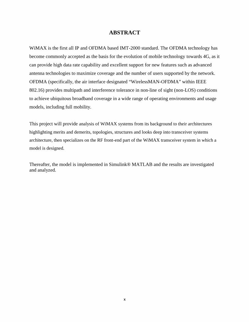
ABSTRACT
WiMAX is the first all IP and OFDMA based IMT-2000 standard. The OFDMA technology has
become commonly accepted as the basis for the evolution of mobile technology towards 4G, as it
can provide high data rate capability and excellent support for new features such as advanced
antenna technologies to maximize coverage and the number of users supported by the network.
OFDMA (specifically, the air interface designated “WirelessMAN-OFDMA” within IEEE
802.16) provides multipath and interference tolerance in non-line of sight (non-LOS) conditions
to achieve ubiquitous broadband coverage in a wide range of operating environments and usage
models, including full mobility.
This project will provide analysis of WiMAX systems from its background to their architectures
highlighting merits and demerits, topologies, structures and looks deep into transceiver systems
architecture, then specializes on the RF front-end part of the WiMAX transceiver system in which a
model is designed.
Thereafter, the model is implemented in Simulink® MATLAB and the results are investigatedand analyzed.

1
1 CHAPTER 1: INTRODUCTION
1.1 Problem DefinitionWireless communication is one of the most rapidly growing industries in today’s society. Cell
phones, wireless email and other recent technological inventions have led to the demand for
wireless access wherever one goes. The result of this demand produced Wi-Fi (wireless fidelity)
“hotspots” in which institutions, like University of Nairobi, installs a wireless network to be
accessed by students and staff while in the campus vicinity. The speed and range limitations have
led to a demand for newer technology to further expand the wireless market, namely WiMAX.
1.2 Objectives1. To study WiMAX systems, based on its background, importance and its technical view
2. To familiarize with the structure, operation and integration of WiMAX transceiver
systems.
3. To design a low-IF RF front-end WiMAX transceiver and demonstrate its functionalities
in the WiMAX system.
1.3 JustificationWiMAX provides an alternative to existing access methods, where it is not feasible to use DSL
or Cable Internet. Typical application will be in remote areas where it is not economically
feasible to have a DSL or Cable Internet.
This project aims to design the part of a WiMAX transceiver that will perform transformation of
signals from baseband frequencies to high frequencies at the transmission end and vice versa at
the receiving end. This gives a chance to understand the principals of operations of these
systems.

2
1.4 Scope
In the last decade telecommunication capabilities and subscriber usage have changed
dramatically. This is especially valid for mobile and Internet based services. Along with the
strong increased usage of mobile and IP based services, the dependency of individuals,
corporations and entire economies on the availability of respective telecommunication networks
has increased dramatically.
1.5 Report Organization
Chapter 2 provides a strong introduction about WiMAX technology, history, deployment status
of this technology, security features, its advantages as a last mile solution and backhauling, its
types, parts and architectures.
Chapter 3 gives a framework on design processes and its parameters
Chapter 4 extends in implementation of the designed model. The result are tabulated and
analyzed and a conclusion documented in chapter 4

3
2 CHAPTER 2: LITERATURE REVIEW
2.1 DefinitionWiMAX is defined as Worldwide Interoperability for Microwave Access by the WiMAX
Forum, formed in June 2001 to promote conformance and interoperability of the IEEE 802.16
standard, officially known as Wireless MAN. It can be considered the evolution of the Wi-Fi,
since it offers higher data rates with coverage of up to 50 kilometers. [1]
2.2 BackgroundThis is the history overview about the 802.16 standards:
802.16 (Dec 2001): Original fixed wireless broadband access for the bands in the 10 –
66GHz. Line-of-sight (LOS) only and Point-to-Multi-Point (MPM).Maximum range of 5
Km
802.16c (2002): Amendment. WiMAX system profiles 10-66GHz
802.16a (Jan 2003): Improvement for non-line-of-sight (NLOS) and providing last-mile
access to a broadband Internet service provider (ISP).
802.16d (Oct 2004): Adds WiMAX system profiles. Maximum range of 50 Km
802.16e (Dec 2005): Layers PHY and MAC to enable moving subscribers. Maximum
range of 5 km.
It is further shown in Table 2.1 and Fig 2.1
In these standards a BS (Base Station) serves the terminals, being necessary the LOS (Line of
Sight) just in the case of 802.16. [1].The modulation used can be OFDM, OFDMA or SOFDMA
(Scalable OFDMA for mobile version), with a number of subcarriers between 128 and 2048
which are modulated with QPSK, 16QAM or 64QAM. The bandwidths used vary between 1.25
and 20 MHz per channel, achieving data rates of up to 100Mbit/s. To support multiple
subscribers, WIMAX supports both TDD (Time Division Duplex) and FDD (Frequency Division
Duplex).

4
Table 2.1 IEEE 802.16 standards
IEEE 802.16 IEEE 802.16
REVISED
IEEE 802.16e IEEE 802.16m
Completed December
2001
May 2004 Mid-2005 November 2010
Spectrum 10 – 66 GHz 2 – 11 GHz 2 – 6 GHz 2 – 6 GHz
Application Backhaul Wireless DSL and
backhaul
Mobile internet Fixed and Mobile
Channel
conditions
Line of sight Non-line of sight Non-line of sight Non-line of sight
Bit rate 32-134Mbps
at 28Mhz
channelizatio
n
Up to 75Mbps at
20Mhz
channelization
Up to 15Mbps at
5Mhz
channelization
Up to 330Mbps
Modulation QPSK,16QA
M, 64QAM OFDM266,OFDM
A 2048,QPSK,
16QAM, 64QAM
OFDM266,OFDM
A 2048,QPSK,
16QAM, 64QAM
OFDM266,OFDM
A 2048,QPSK,
16QAM, 64QAM
Channel
bandwidths
20,25,28
MHz
Selectable channel
bandwidths
between 1.5 – 20
MHz
Selectable channel
bandwidths
between 1.5 – 20
MHz
20MHz

5
Fig 2.1 WiMAX standards
There are four main frequency operating bands:
License-exempt 5 GHz: frequencies between 5.25 and 5.28 GHz are used typically in
rural areas with a low population density.
Licensed 3.5 GHz: frequencies between 3.4 and 3.6 GHz are designated for fixed
wireless access in most of the countries.
Licensed 2.5 GHz: frequencies between 2.5 and 2.7 GHz have been allocated in some
countries as USA, Mexico, Brazil and some Southeast Asian countries.
Lower 700 MHz: these frequencies are currently vacant ore used for analog TV (which is
going to disappear), and they are suitable for wireless transmission because the radio
waves can penetrate obstacles and propagate further.
WiMAX is suitable to both continual and burst traffic, so that it is independent of the protocol
used. Thus, it can transport IP, Ethernet, ATM and support multiple simultaneous services
offering QoS (Quality of Service), so it is adequate for VoIP, data and video. In terms of
security, WiMAX has advanced mechanisms for data encryption such as RSA and 3DES
algorithms, and it uses PKM (Privacy Key Management) for authentication between base station
and subscriber station.
The most important application scenarios in which WIMAX can be easily implemented are:
6
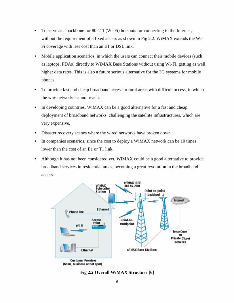
To serve as a backbone for 802.11 (Wi-Fi) hotspots for connecting to the Internet,
without the requirement of a fixed access as shown in Fig 2.2. WiMAX extends the Wi-
Fi coverage with less cost than an E1 or DSL link.
Mobile application scenarios, in which the users can connect their mobile devices (such
as laptops, PDAs) directly to WiMAX Base Stations without using Wi-Fi, getting as well
higher data rates. This is also a future serious alternative for the 3G systems for mobile
phones.
To provide fast and cheap broadband access to rural areas with difficult access, in which
the wire networks cannot reach.
In developing countries, WiMAX can be a good alternative for a fast and cheap
deployment of broadband networks, challenging the satellite infrastructures, which are
very expensive.
Disaster recovery scenes where the wired networks have broken down.
In companies scenarios, since the cost to deploy a WiMAX network can be 10 times
lower than the cost of an E1 or T1 link.
Although it has not been considered yet, WiMAX could be a good alternative to provide
broadband services in residential areas, becoming a great revolution in the broadband
access.
Fig 2.2 Overall WiMAX Structure [6]

7
2.3 WiMAX Security
Designed by the IEEE 802.16 committee, WiMAX was developed after the security failures that
plagued early IEEE 802.11 networks. Recognizing the importance of security, the 802.16
working groups designed several mechanisms to protect the service provider from theft of
service, and to protect the customer from unauthorized information disclosure.
The standard includes state-of-the-art methods for ensuring user data privacy and preventing
unauthorized access, with additional protocol optimization for mobility. A privacy sub layer
within the WiMAX MAC handles security. The key aspects of WiMAX security are as follow.
Support for privacy: User data is encrypted using cryptographic schemes of proven robustness
to provide privacy.
Device/user authentication: WiMAX provides a flexible means for authenticating subscriber
stations and users to prevent unauthorized use
Flexible key-management protocol: The Privacy and Key Management Protocol Version 2
(PKMv2) is used for securely transferring keying material from the base station to the mobile
Protection of control messages: using message digest schemes, such as AES-based CMAC or
MD5-based HMAC.11, protects the integrity of over-the-air control messages.
Support for fast handover: To support fast handovers, WiMAX allows the MS to use pre-
authentication with a particular target BS to facilitate accelerated reentry.

8
Fig 2.3 WiMAX Security structure
With all the previous facts, we can easily sort a great list of benefits, and also drawbacks, of the
WiMAX technology:
2.4 Benefits:
High bandwidth and data rate.
Long range.
Multi-Application.
Flexible architecture.
High security.
QoS.
Interoperability.
Low cost and quick deployment.
Worldwide standardization.
2.5 Drawbacks: Power limitations in order to avoid interferences with other systems.
9
It requires strong electrical support.
Line of sight is required for connections of over 5 miles.
Because the development of WiMAX has not been completed yet, and its use is not
widespread, companies are hesitant of setting up WIMAX base stations
2.6 Types of WiMAXThere are two types of WiMAX system:-
Fixed WiMAX
Mobile WiMAX
2.6.1 Fixed WiMAX
Fixed WiMAX refers to the system built using 802.16-2004 ('802.16d') as the air interface
technology.[1] Line Of Sight transmissions use higher frequencies up to 66GHz.The fixed
version of WiMAX, based on 802.16-2004, can provide data rates up to 75 megabits per second
(Mbps) per four-sector base station (18.7-Mbps peak data rate per sector) with typical cell sizes
of 2 to 10 kilometers in urban and suburban areas (50 km in rural areas).This is enough
bandwidth to simultaneously support (through a single base station) more than 60 businesses
with T1/E1-type connectivity and hundreds of homes with DSL-type connectivity.
Fixed Mobile is suitable for fixed Wireless Landline communications and fixed computers to
provide broad band wireless network.
2.6.2 Mobile WiMAX
Mobile WiMAX refers to the system built using 802.16e-2005 as the air interface technology.
"Mobile WiMAX" implementations are therefore frequently used to deliver pure fixed services.
[1]
WiMAX uses a Lower Frequency Range – 2 GHz to 11 GHz (Similar to Wi-Fi).
Since, Lower-wavelength transmissions are not as easily disrupted by physical obstructions --
they are better able to diffract, or bend, around obstacles. Hence, lower frequency ranges are
suitable for mobile communication and mobile wireless internet service.

10
Mobile WiMAX is suitable for Mobile communication and mobile wireless broadband service in
cell phones, smart phones and laptops as shown in Fig 2.4. It allows people to communicate
while walking or riding in cars and provides a mobile voice over IP (VoIP) and higher-speed
data alternative to the cellular networks (GSM, TDMA, CDMA).
Fig 2.4 Mobility and coverage vs. Data rates in different topologies [6]
Future of WiMAX
WiMAX 2 is an evolution of the WiMAX standard that is currently used by Clearwire and Sprint
to deliver the fastest wireless data services in the United States, with typical download speeds in
the 4Gbps to 5Gbps range. [2]
The WiMAX 2 standard, formally known as 802.16m, is due be finalized by the Institute of
Electrical and Electronics Engineers (IEEE) by November 2011. 802.16m is expected to be
significantly faster than its predecessor and the WiMAX Forum industry group projects that it

11
will be able to deliver average downlink speeds of more than 100Mbps to users.
But while 802.16m will give WiMAX a major speed boost, don't expect it to propagate any
further than the current WiMAX technology that covers around 31 square miles per access point.
802.16m will also be backward compatible with 802.16e, the WiMAX standard currently used
by operators in the United States. This means that when U.S. ISP Clearwire upgrades to the new
standard it will be able to do so at a relatively low cost and with minimal disruption.
Some of the objectives for the improvement of WiMAX are:-
• WiMAX II, 802.16m will be proposed for IMT-Advanced 4G.
• WiMAX-m concentrating on MIMO-AAS, mobile multi-hop relay networking & related
developments to deliver 10X & higher Co-Channel reuses multiples.
• Mobile WiMAX based upon 802.16e-2005 has been accepted as IP-OFDMA for
inclusion as the sixth wireless link system under IMT-2000. This can hasten acceptance
by regulatory authorities and operators for use in cellular spectrum.
• Goal is to achieve 100 Mbit/s mobile and 1 Gbit/s fixed-nomadic bandwidth as set by
ITU for 4G NGMN (Next Generation Mobile Network) systems through the adaptive use
of MIMO-AAS and smart, granular network topologies.
2.7 Parts of WiMAX SystemTypically, a WiMAX system consists of two parts:
1. WiMAX Base Station
2. WiMAX Receiver (subscriber Unit)
2.7.1 WiMAX Base Station
Base station consists of indoor electronics and a WiMAX tower. Typically, a base station can
cover up to 10 km radius (Theoretically, a base station can cover up to 50 kilo meter radius or 30
miles, however practical considerations limit it to about 10km or 6 miles). Any wireless node
within the coverage area would be able to access the Internet. Several base stations can be
connected with one another by use of high-speed backhaul microwave links. This would allow

12
for roaming by a WiMAX subscriber from one base station to another base station area, similar
to roaming enabled by Cellular phone companies.
2.7.2 WiMAX Receiver (Subscriber Unit)
This is the Digital Base band Receiver that processes the I/Q Data. The receiver and antenna
could be a stand-alone box or a PCMCIA (Personal Computer Memory Card International
Association) card that sits in your laptop or computer. Access to WiMAX base station is similar
to accessing a Wireless Access Point in a Wi-Fi network, but the coverage is more.
2.8 WiMAX Architecture
Fig 2.5 WiMAX Architecture on Internet protocol
2.8.1 OFDM (Orthogonal Frequency Division Multiplexing)
It is a digital encoding and modulation technology. It achieves high data rate and efficiency by
using multiple overlapping carrier signals.
Key advantage of OFDM over single carrier modulation schemes is the ability to deliver higher
bandwidth efficiency. Hence, higher data throughput even in NLOS links suffering from
significant degradation due to multi path conditions.

13
2.8.2 MAC (Media Access Control) Layer – Data link layer
The main focus is to manage the resources of the air link in an efficient manner. The MAC layer
consists of three sub-layers.
Service specific convergence sub-layer (SSCS) provides an interface to the upper layer
entities through a CS service access point (SAP).
The MAC common part sub-layer (CPS) provides the core MAC functions, including
uplink scheduling, bandwidth request and grant, connection control, and automatic repeat
request (ARQ).
Privacy sub-layer (PS) provides authentication and data encryption functions.
Figure 2.1 MAC layer functions
2.8.3 PHY Layer (physical layer)
This standard specifies the air interface of a fixed (stationary) point-to-multipoint (PMP)
BWA system providing multiple services in a wireless metropolitan area network.

14
It also specifies an optional mesh topology enhancement to the medium access control
layer.
The Wireless MAN MAC is capable of supporting multiple physical layer (PHY)
specifications optimized for the frequency bands of application. The standard includes
PHY specifications, applicable to systems operating below 11 GHz and between 10 GHz
and 66 GHz. The 10–66 GHz air interface, based on single-carrier modulation, is known
as the WirelessMAN-SC air interface.
For frequencies below 11 GHz, the WirelessMAN-SCa, Wireless- MAN-OFDM and
WirelessMAN-OFDMA air interfaces are specified.
Figure 2.2 PHY layer functions
2.9 RF front-end WiMAXAn RF front end system refers to the analog front end of the wireless communication system.
The digital baseband signals cannot be transmitted directly through wireless channels due to
properties of the electromagnetic waves. Therefore, these signals must be converted to analog, up
converted to higher frequencies, and transmitted through the channel. The received signals are

15
down converted to the baseband frequency then converted to digital again. Processes done to the
analog signal in the RF front end includes filtering, amplification, and mixing.
Fig. 2.6
2.9.1 RF Transmitters
A typical RF transmitter consists of a power amplifier and a mixer because these components
add the most serious impairments to the transmitter. The mixer introduces phase noise, spurious
frequencies and nonlinearity. The power amplifier introduces nonlinearity.
Fig 2.7 A Schematic of an RF transmitter.
DSP DACRF FRONT-END
(TRANSMITTER)
RF TX
CHANNEL
RF RXRF FRONT-END
(RECEIVER)ADCDSP
Fig 2.6 Diagram of an overall wireless system structure. Antennas are sometimesincluded with RF frond end.

16
2.9.2 RF Receivers
A typical RF receiver has only the low noise amplifier (LNA) and the mixer. The LNA
introduces noise and nonlinearity. The mixer introduces phase noise and nonlinearity.
Fig 2.8 A schematic of an RF receiver.
2.9.3 Power Amplifiers (PA)
An amplifier is a device designed to increase signal power levels. There are mainly two types of
amplifiers in RF front end circuits; these are power amplifiers (PA), and low noise amplifiers
(LNA). Power amplifiers are mainly present in the transmitters, and are designed to raise the
power level of the signal before passing it to the antenna. This power boost is crucial to achieve
the desired signal to noise ratio at the receiver, and without which received signals would not be
detectable.
Output power= Input power*Gain
For the power amplifier it is necessary to have as high gain as possible, while adding as little
distortion to the signal as possible i.e. be as linear as possible. For small and mobile transmitters
there is usually another factor not less important; that is power efficiency since these devices are
usually battery driven. Unfortunately, from a circuit design point of view, increasing the power
efficiency would mean driving the device more and more into nonlinearity region which means
that the amount of distortion will increase. The problem of nonlinearity is not so serious for
applications where information is put in the carrier signal’s phase. However, with the recent jam
in the frequency bandwidth, new regulations have made strict bands that modulation schemes
can work in, while at the same time higher data rates need to be achieved, therefore, it is logical
to move to modulation schemes that carry information in both amplitude and phase. If the
amplitude carries information then irreversible envelope distortions will affect the received
signal quality and in turn increase the bit error rate of the received signal. Therefore, in modeling

17
a power amplifier for wide band applications the most important aspect to model is the device
nonlinearity that the amplifier introduces to the system.
2.9.4 Low Noise Amplifiers (LNA)
Low Noise Amplifier (LNA) is the first amplifier in the RF receiver frontend; typically it is the
first or second component after the antenna. It is designed to increase the power of the received
signal which is usually very weak (could be as weak as -200dBm). LNAs are designed to add as
little noise as possible, such that the signal to noise ratio (SNR) stays above the minimum
required SNR of the receiver. The SNR is defined as the ratio between the wanted signal and the
noise and is usually specified in dBs. Every receiver has a minimum SNR at its input, if the SNR
drops below this value, the error in the received signal will be high. Another important
performance figure for RF receivers is the noise factor F which is defined as the SNRin/SNRout. It
is a measure of how much noise the receiver will add. If F is measured in dBs instead of linear
scale, it will be known as the noise factor. The notation F is usually used for both noise figure
and noise factor.
2.9.5 Mixers
A mixer can be defined as “a three port device that uses a nonlinear or time –varying element to
achieve frequency conversion.”[4] Normally in a wireless communication systems all signal
processing is done in baseband because it is easy to process low frequency signals. To be able to
transmit through the wireless channel however the signal has to be brought to a higher frequency,
which is done by modulation and up conversion in the transmitter, this effect has to be undone in
the receiver which corresponds to demodulation and down conversion in the receiver. Up and
down conversions are done with mixers.

18
Fig 2.9 A Schematic of an up or down conversion Mixer
Where:
fIF - the intermediate frequency, equal to fRF - fLO
fLO - the frequency of the Local Oscillator
fRF - the carrier of the desired signal
tS - sample time
For up-conversion: fIF + fLO = fRF
Fig 2.10 Mixer modeling in RF Blockset® ; up conversion
For down-conversion: fRF - fLO = fIF

19
Fig 2.11 Diagram of a down converter mixer
Fig 2.12 Mixer modeling in RF Blockset® ; down conversion

20
Fig 2.13 Frequency bandwidth calculation in RF Blockset® MATLAB [5]
Where :
fc – center frequency
tS - sample time△f - represents the bandwidth of the WiMAX channel
N – number of sub-bands (finite impulse response filter length)
Fig 2.14 Base-band equivalent spectrum

21
There are many approaches to model mixers at the system level that depends on which type of
impairment the model addresses. Power levels of spurious components are modeled using
intermodulation tables. Nonlinearity which is an inherent phenomenon in mixers is modeled
using IIP3 and 1dB compression point. The main impairment related to mixers that highly effect
the performance of the overall system is the phase noise.
2.9.6 Filters
Radio frequency (RF) and microwave filters represent a class of electronic filter, designed to
operate on signals in the megahertz to gigahertz frequency ranges (medium frequency to
extremely high frequency). This frequency range is the range used by most broadcast radio,
television, wireless communication (cell phones, Wi-Fi, etc...), and thus most RF and microwave
devices will include some kind of filtering on the signals transmitted or received. Such filters are
commonly used as building blocks for duplexers and diplexers to combine or separate multiple
frequency bands.[6]
Four general filter functions are desirable:
• Band-pass filter: select only a desired band of frequencies
• Band-stop filter: eliminate an undesired band of frequencies
• Low-pass filter: allow only frequencies below a cutoff frequency to pass
• High-pass filter: allow only frequencies above a cutoff frequency to pass
Fig 2.15 A schematic of an RF filter

22
The antenna picks up RF signals that fall in its band-pass, which go through a band selection
filter ( RF filter)that removes undesired signals. The IF filter is either a low-pass IF filter for the
zero-IF architecture or band-pass IF filter for the low-IF architecture.
Fig 2.16 A schematic of a bandpass filter
Fig 2.17 A schematic of a lowpass filter
2.10 Transceiver systems architectures
Nowadays, the availability of many wireless standards that can be implemented in 4G, which
associated with the continuous emergence of new wireless technologies, suggests the use of a
reconfigurable multi standard receiver. The use of such flexible architecture can be achieved
through the use of software defined radio (SDR). This term refers to a radio receiver,
programmable by software, that defines the radio parameters and which can be upgraded to face
the requirements of new forthcoming protocols. The goal of SDR is to perform the signal
digitalization as near as possible to the antenna, hence allowing the use of digital programmable
hardware, such as digital signal processors (DSPs).

23
An ideal SDR would consist in an analog to digital conversion right after the antenna, demanding
an ADC with bandwidth about 6GHz and up to 14 bits of resolution. However, according to
state-of-the-art analog-to-digital converters (ADCs) this possibility is still unfeasible.
Consequently the digitalization of the signal has to be performed in baseband frequency, since
that result is a more reasonable requirement for the ADC. Consequently, an analysis on the
architecture of these receivers is performed, specifically their multi-standard and integration
capabilities.
A conventional architecture choice is the super heterodyne receiver, based on its performance in
terms of sensitivity and selectivity, and is achieved mostly due to its discrete filters. Therefore,
the use of a RF (Radio Frequency), IR (Image Rejection) and IF (Intermediate Frequency) filters
turns this architecture unsuitable for integration and consequently for multi-standard purposes
that would require even more off-chip filters.
Fig 2.18 super heterodyne transceiver architecture
The direct conversion receiver [7] or Zero-IF receiver uses only a discrete RF filter, suppressing
the others off-chip filters. This is performed using a single mixer stage translating the signal
directly to baseband. Thus, integration capability is improved like as multi-standard, since
channel selection is performed in baseband by a low pass filter that could be programmable to
support diverse standards. In a Low-IF topology [8] the RF signal is translated to intermediate
frequency closer to the baseband frequency. Besides maintaining the same level of integration as
the Zero-IF, multi-standard ability is affected, since the more severe constraints are posed on
bandpass filter and ADC for wide channel bandwidth, leading to an increase in power
consumption.

24
Fig 2.20 Low-IF transceiver architecture
Wideband IF double conversion [9] receiver performs the carrier translation to baseband in a
similar manner that super heterodyne solution. However, this topology allows a higher level of
integration since it uses only the discrete frontend RF filter. This topology requires six high
linear mixers that increases the overall power dissipation of the receiver.
Multi-standard configurability is still possible since channel filtering is performed in baseband
like in Zero-IF approach. A Zero-IF architecture is therefore the solution that presents more
advantages regarding a multi standard implementation. Such architecture was proposed on [10],
reinforcing the use of this topology for multi-standard wireless applications.
Fig 2.21 Wideband IF double conversion transceiver architecture

25
In concrete terms, the present need demands the capability by a single transceiver to
operate on RF standards with various carrier frequencies, modulation schemes, channel
bandwidths, sensitivity, and selectivity requirements, and also to fulfill integration and
power-consumption specifications. Such a performance is impossible to carry out by
heterodyne architectures both because of the nonzero IF frequency that restricts their use to a
unique RF standard and the presence of bulky off-chip filters that cannot be removed, thus
severely limiting the possibility of integration. This is the reason why direct-conversion (zero
IF) transceivers have gained interest during the last decade since they use few on-chip
components, do not need off-chip filters, and are well suited to RF multistandard operations
due to zero IF frequency. The interest for zero IF transceivers have grown despite the
numerous defaults inherent to the RF front-ends of these architectures compared to their
heterodyne counterparts. Among these defaults, sensitivity to dc offsets and second-order
intermodulation are of great importance. These can be completely or partially avoided
through the use of low IF receivers that present the same integration level, RF multistandard
operation potential, do not suffer from dc offsets, and are less sensitive to second-order
intermodulation [11], [12]. Designing circuits able to fulfill all the specifications mentioned
above is both a technological challenge and an economic stake. To this end, broadband
components integrated in zero/low IF transceivers represent a solution. In this paper, we
focus on the RF front-end of the communications system with particular attention devoted to
the demodulator. In common receivers, the classical in-phase/quadrature (I/Q) architecture is
adopted. To operate properly, this one needs a nearly perfect 90 phase shift between its I and
Q paths, which cannot be guaranteed over a very broad bandwidth. This is the factor that
clearly limits the potential of the I/Q demodulator for RF multistandard operations involving
standards with carrier frequencies that extend from 1 to 20 GHz. We present here the design
and performance of a monolithic microwave integrated circuit (MMIC) broadband
demodulator operating in the 1–20-GHz frequency range to be used in a low IF receiver that
is less sensitive to phase mismatch between its paths than the I/Q demodulator.

26
Architecture DiscreteFilters
IntegrationLevel
Multi-StandardAbility
Power
Super heterodyne RF, IR, IF Low Low High
Zero-IF RF High High Low
Low-IF RF High Medium Medium
Wideband IF RF High High Medium
Table 2.2 Transceiver’s architectures characteristics

27
3 CHAPTER 3: METHODOLOGY
3.1 Design
The design of the low-IF RF front-end WiMAX transceiver involved integration of variouscomponents to work as a unit. The overall implemented model and flow chart for the transmitterand the receiver are shown in Fig 3.1 and Fig 3.2 respectively.
Baseband –equivalentsignalsource
Basebandfilter/ IFfilter
Mixer (upconversion)
Baseband–equivalentsignal sink
Basebandfilter/ IFfilter
Mixer(downconversion)
Highpoweramplifier
Lownoiseamplifier
RF filter
RF filter
TRANSMITTER BLOCK
RECEIVER BLOCK
CHANNEL
Fig 3.1 design of the low-IF RF front-end WiMAX transceiver

28
3.1.1 Flowchart
(1-10)MHzrange?
(2.4-2.6)GHzrange?
(2.4-2.6)GHzrange?
(1-10)MHzrange?
Add LO of2.5GHz
Channel; addsnoise to thesignal
subtract LOof 2.5GHz
Signal sink
Start
End
generatedsignal (2-
3)MHz
Display
NO
NO
NO
NO
YES
YES
YES
YES
Fig 3.2 Flow chart of the low-IF RF front-end WiMAX transceiver model

29
3.2 Design specifications
3.2.1 Baseband equivalent signal source
The signal source in the model includes the following components:
• A Random Integer Generator block, used as source of random data• A modulator and a pulse shaping filter that performs QPSK modulation and root raised
cosine pulse shaping.• An Up converter block that multiplies the modulated signal by a carrier frequency.
. The sample frequency is set at 8 MHz
3.2.2 Baseband equivalent signal sink
The signal sink in the model includes the following components:
• A Down converter block that converts the signal from real passband to complexbaseband.
• A root raised cosine pulse shaping filter that decimates back to one sample per symbol,and a QPSK demodulator block.
• BER calculation block
The sample frequency is set 8 MHz with a Baseband bandwidth of 1 MHz
3.2.3 IF filter
Two bandpass IF filter blocks are used. Design method was Butterworth of order 3. Themagnitude response of a Butterworth filter is maximally flat in the passband and monotonicoverall. 1MHz and 10MHz where the lower passband edge frequency and upper passband edgefrequency respectively.
fIF = 10Mhz maximum
3.2.4 Mixer
Up converter
fIF + fLO = fRF
Local oscillator frequency was set at 2.5GHz.
fRF= (2500+10)MHz = 2.51Ghz

30
Down converter
fRF - fLO = fIF
Local oscillator frequency was set at 1.8GHz.
fIF = (2510 - 1800)MHz = 710Mhz
This satisfies the Low-IF architecture theory in which the RF signal is translated to intermediatefrequency closer to the baseband frequency.
3.2.5 RF filter
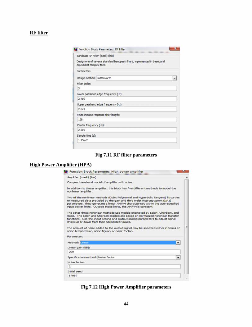
Two bandpass RF filter blocks are used. Design method was Butterworth of order 3. Themagnitude response of a Butterworth filter is maximally flat in the passband and monotonicoverall. 2.4GHz and 2.6GHz where the lower passband edge frequency and upper passband edgefrequency respectively.
3.2.6 LNA and HPA
LNA; Gain = 120
HPA; Gain = 200
3.2.7 Channel
An AWGN Channel block set to Eb/No mode. It specifies two bits per symbol because themodulation format is QPSK. The signal power is 1/ (2*8) watts. This is because the originalsignal power at the modulator is 1 watt. The root-raised cosine filter up samples the signal by afactor of 8, which reduces the power by that factor. The frequency up conversion block outputtakes only the real part of the signal, thereby reducing the power again, this time by a factor of 2.

31

32
4 CHAPTER 4: RESULTS AND EVALUATION
4.1 Implemented Simulink modelThe model in Fig 4.1 was simulated in MATLAB Simulink®. and its components parameters
are shown in Table 4.1.
Fig 4.1 Low-IF RF front-end WiMAX transceiver simulated model
Table 4.1 Parameter configurations
LNA HPA RF filter IF filter Mixer Power
amplifier
Channel
Gain (dB) 120 200 -1 0 2 100 0
NF (dB) 1 2 1 5 0 0 8
IIP3 (dBm) 1 - - - 1 0 1
IIP2 (dBm) 0 - - - 0 0 1
Order - - 3 3 - - -

33
4.2 Results
Fig 4.2 Spectrum of Generated and Received signals
BER = 0.5
Fig 4.3 Transmitted and Received QPSK Modulated signals

34
Fig 4.4 Spectrum of Transmitted and Received baseband signals
Fig 4.5 Transmitted Constellations

35
Fig 4.6 Received Constellations
4.3 Evaluation
A random integer signal of about 20 KHz was generated and received as shown in Fig 4.2. The
generated signal was passed through a modulator and a pulse shaping filter that performed QPSK
modulation and root raised cosine pulse shaping as shown in Fig 4.3.
Baseband equivalent signal of frequency (2- 3) MHz was generated with a bandwidth of 1 MHz
This signal was transmitted and received after being passed through the Low-IF RF front-end
topology system as illustrated in Fig 4.4.
Fig 4.7 showed the scatter plot of the transmitted signal

36
Fig 4.8 showed the scatter plot of the received signal, and nonlinearity in the amplifiers and
mixers caused the signal constellation to be diffused. A nearly perfect 90° phase shift between
the I and Q paths, was due to the narrow bandwidth of the baseband signal.
BER was 0.5 due to a relatively low noise figure (NF) of the system. Excessive noise figure in
The system would have caused the noise to overwhelm the signal, making the signal
unrecoverable.

37
5 CHAPTER 5: CONCLUSION AND RECOMMENDATIONS
5.1 Conclusion
Technical aspects, scope and history WiMAX Technology in the present scenario and in the
future have been studied. And it can be easily infer from this report that the WiMAX Technology
is an emerging Technology which is poised to revolutionize the world. The objectives as stated
in the introduction where met.
In the latter part of the project methodology of modeling, analysis and design package for a Low-
IF RF front-end WiMAX transceiver was demonstrated. The model was implemented and
demonstrated successfully using MATLAB Simulink® R2008b.
5.2 Recommendations
This project work can be extended by:
a) adding a model for the analog to digital converter to the transceiver; this will add the
effect of quantization noise and nonlinearity.
b) Implementing the design in hardware PCB design and fabrication
38
6 REFERENCES
[1] http://en.wikipedia.org/wiki/WiMAX
[2] http://www.cio.co.ke/
[3] www.ceenet.org/workshops/lectures2004/Richard_Perlman/additional_materials_(wimax
)/proxim-wimax.ppt
[4] www.wimaxforum.org
[5] www.mathworks.com
[6] www.google.com
[7] A Abidi, “Direct-conversion radio transceivers for digital communication”, IEEE J.
Solid-State Circuits, vol.30, no.12, pp. 1399-1410, 1995.
[8] J. Crols and M.S.J. Steyaert, "Low-IF topologies for high-performance analog front ends
of fully integrated receivers," IEEE Trans. Circuits Syst. II, Analog Digit. Signal
Process., vol.45, no.3, pp.269–282, March 1998.
[9] J.C.Rudell, et al, “A 1.9 Ghz Wide-Band IF Double Conversion CMOS Receiver for
Cordless Telephone Applications”, IEEE J. Solid- State Circuits, pp 2071-2088, Vol 32,
Dec 1997.
[10] X. Li, M. Ismail, “ A single-chip cmos front-end receiver architecture for multi-
standard wireless applications”, ISCAS’01, Sydney, Australia, May 2001, pp. 374–377.
[11] J. Crols and M. S. J. Steyaert, “Low-IF topologies for high performance analog
front ends of fully integrated receivers,” IEEE Trans. Circuits Syst II, Analog Digit.
Signal Process., vol. 45, no. 3, pp. 269–282, Mar. 1998.
[12] J. Crols and M. S. J. Steyaert, “A single-chip 900 MHz CMOS receiver front-end
with a high performance low-IF topology,” IEEE J. Solid- State Circuits, vol. 30, no. 12,
pp. 1483–1492, Dec. 1995.

39
7 APPENDICES
APPENDIX A SIMULATED MODEL
Fig 7.1 Actual simulated model

40
APPENDIX B CONFIGURATIONSBaseband equivalent signal source
Fig 7.2 Signal source
Baseband equivalent signal source
Fig 7.3 Signal sink
IF filter
Fig 7.4 IF filter parameters

41
Mixers
Mixer Upconverter
Fig 7.5 Mixer Upconverter circuit
Fig 7.6 Input port parameters for physical circuits

42
Fig 7.7 Upconverter mixer parameters
Fig 7.8 Power amplifier parameters

43
Mixer Downconverter
Fig 7.9 Mixer Downconverter circuit
Fig 7.10 Downconverter mixer parameters
44
RF filter
Fig 7.11 RF filter parameters
High Power Amplifier (HPA)
Fig 7.12 High Power Amplifier parameters

45
Low Noise Amplifier(LNA)
Fig 7.13 Low Noise Amplifier parameters
Channel
Fig 7.14 AWGN block parameters

46
APPENDIX C OTHER RESULTS
Fig 7.15 Bandpass signals spectrum
Fig 7.16 Transmitted signal spectrum

47
Fig 7.17 Received signal spectrum

48