Embed Size (px)
Citation preview
41
RF-Kinect: A Wearable RFID-based Approach Towards 3D BodyMovement Tracking
CHUYU WANG, Nanjing University, CHNJIAN LIU, Rutgers University, USAYINGYING CHEN∗, Rutgers University, USALEI XIE∗, Nanjing University, CHNHONGBO LIU, Indiana University-Purdue University Indianapolis, USASANGLU LU, Nanjing University, CHN
The rising popularity of electronic devices with gesture recognition capabilities makes the gesture-based human-computerinteraction more attractive. Along this direction, tracking the body movement in 3D space is desirable to further facilitatebehavior recognition in various scenarios. Existing solutions attempt to track the body movement based on computer versionor wearable sensors, but they are either dependent on the light or incurring high energy consumption. This paper presentsRF-Kinect, a training-free system which tracks the body movement in 3D space by analyzing the phase information of wearableRFID tags attached on the limb. Instead of locating each tag independently in 3D space to recover the body postures, RF-Kinecttreats each limb as a whole, and estimates the corresponding orientations through extracting two types of phase features,Phase Difference between Tags (PDT) on the same part of a limb and Phase Difference between Antennas (PDA) of the same tag.It then reconstructs the body posture based on the determined orientation of limbs grounded on the human body geometricmodel, and exploits Kalman filter to smooth the body movement results, which is the temporal sequence of the body postures.The real experiments with 5 volunteers show that RF-Kinect achieves 8.7◦ angle error for determining the orientation oflimbs and 4.4cm relative position error for the position estimation of joints compared with Kinect 2.0 testbed.
CCS Concepts: • Networks → Sensor networks; Mobile networks; • Human-centered computing → Mobile devices;
Additional Key Words and Phrases: RFID; Body movement tracking
ACM Reference Format:ChuyuWang, Jian Liu, Yingying Chen, Lei Xie, Hongbo Liu, and Sanglu Lu. 2018. RF-Kinect: AWearable RFID-based ApproachTowards 3D Body Movement Tracking. Proc. ACM Interact. Mob. Wearable Ubiquitous Technol. 2, 1, Article 41 (March 2018),28 pages. https://doi.org/10.1145/3191773
∗Yingying Chen and Lei Xie are the co-corresponding authors, Email: [email protected], [email protected].
Authors’ addresses: Chuyu Wang, Nanjing University, State Key Laboratory for Novel Software Technology, 163 Xianlin Ave, Nanjing, 210046,CHN; Jian Liu, Rutgers University, Department of Electrical and Computer Engineering, North Brunswick, NJ, 08902, USA; Yingying Chen,Rutgers University, Department of Electrical and Computer Engineering, North Brunswick, NJ, 08902, USA; Lei Xie, Nanjing University, StateKey Laboratory for Novel Software Technology, 163 Xianlin Ave, Nanjing, 210046, CHN; Hongbo Liu, Indiana University-Purdue UniversityIndianapolis, Department of Computer, Information and Technology, Indianapolis, IN, 46202, USA; Sanglu Lu, Nanjing University, State KeyLaboratory for Novel Software Technology, 163 Xianlin Ave, Nanjing, 210046, CHN.
Permission to make digital or hard copies of all or part of this work for personal or classroom use is granted without fee provided thatcopies are not made or distributed for profit or commercial advantage and that copies bear this notice and the full citation on the firstpage. Copyrights for components of this work owned by others than ACM must be honored. Abstracting with credit is permitted. To copyotherwise, or republish, to post on servers or to redistribute to lists, requires prior specific permission and/or a fee. Request permissions [email protected].© 2018 Association for Computing Machinery.2474-9567/2018/3-ART41 $15.00https://doi.org/10.1145/3191773
Proceedings of the ACM on Interactive, Mobile, Wearable and Ubiquitous Technologies, Vol. 2, No. 1, Article 41. Publication date: March 2018.
41:2 • C. Wang et al.
1 INTRODUCTIONThe gesture-based Human-Computer Interaction (HCI) embraces an increasing number of practical usage enabledby the growing popularity of electronic devices with gesture recognition capabilities. Recent survey reveals thatthe global gesture recognition market is anticipated to reach USD 48.56 billion by 2024 [4]. In particular, thesuccess of Microsoft Kinect [8] in tracking human gestures in gaming consoles has induced many emergingapplications to adopt gesture recognition solutions in the fields like healthcare, smart homes, mobile robot control,etc. For example, numerous applications are developed to monitor human’s well-being based on their activities(such as fitness, drinking, sleeping, etc.) with either wearable devices or smartphones. The success of gestureand activity recognition leads to a growing interest in developing new approaches and technologies to track thebody movement in 3D space, which can further facilitate behavior recognition in various occasions, such as VRgaming, mobile healthcare, and user access control.Existing solutions for body movement recognition fall into three main categories: (i) Computer vision-based
solutions, such as Kinect and LeapMotion [5, 8], leverage the depth sensors or infrared cameras to recognizebody gestures and allow the user to interact with machines in a natural way. However, these methods suffer fromseveral inherent disadvantages of computer vision including light dependence, dead corner, high computationalcost, and ambiguity of multi-people. (ii) Sensor-based solutions, such as the smartwatch and wristband [3], aredesigned to track the movement of the limbs based on the accelerator or gyroscope readings. But these systemsusually require the user to wear different kinds of sensing devices, which present short life cycles due to thehigh energy consumption. Further, there are also some products (i.e., Vicon [6]) integrating the informationfrom both cameras and wearable sensors to accurately track the body movement, however the high price of theinfrastructure is not affordable for many systems. (iii) Wireless signal-based solutions [17, 25] capture the specificgestures based on the changes of some wireless signal features, such as the Doppler frequency shift and signalamplitude fluctuation. But only a limited number of gestures could be correctly identified due to the high cost oftraining data collection and the lack of capabilities for multi-user identification.With the rapid development of RFID techniques [34, 41], RFID tag now is not only an identification device,
but also a low power battery-free wireless sensor serving for various applications, such as the localization andmotion tracking. Previous studies, such as Tagoram [41] and RF-IDraw [35], could achieve cm-level accuracy ontracking an individual RFID tag in 2D space (i.e., a tagged object or finger). Further, Tagyro [39] could accuratelytrack the 3D orientation of objects attached with an array of RFID tags, but it only works for objects with thefixed geometry and rotation center. However, due to the complicated body movement involving multiple degreesof freedom, the problem of 3D RFID tag tracking associated with the human body movement, including bothlimb orientation and joint displacement (e.g., elbow displacement), remains elusive.Inspired by these advanced schemes, we explore the possibility of tracking the human body movement in 3D
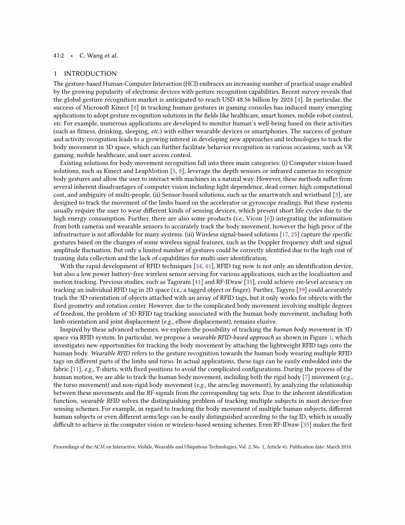
space via RFID system. In particular, we propose a wearable RFID-based approach as shown in Figure 1, whichinvestigates new opportunities for tracking the body movement by attaching the lightweight RFID tags onto thehuman body.Wearable RFID refers to the gesture recognition towards the human body wearing multiple RFIDtags on different parts of the limbs and torso. In actual applications, these tags can be easily embedded into thefabric [11], e.g., T-shirts, with fixed positions to avoid the complicated configurations. During the process of thehuman motion, we are able to track the human body movement, including both the rigid body [7] movement (e.g.,the torso movement) and non-rigid body movement (e.g., the arm/leg movement), by analyzing the relationshipbetween these movements and the RF-signals from the corresponding tag sets. Due to the inherent identificationfunction, wearable RFID solves the distinguishing problem of tracking multiple subjects in most device-freesensing schemes. For example, in regard to tracking the body movement of multiple human subjects, differenthuman subjects or even different arms/legs can be easily distinguished according to the tag ID, which is usuallydifficult to achieve in the computer vision or wireless-based sensing schemes. Even RF-IDraw [35] makes the first
Proceedings of the ACM on Interactive, Mobile, Wearable and Ubiquitous Technologies, Vol. 2, No. 1, Article 41. Publication date: March 2018.
RF-Kinect: A Wearable RFID-based Approach Towards 3D Body Movement Tracking • 41:3
!"#$"
%&'()
"#$"#*
"#+!$
!$#,
-&'()
!.
!"#,
"
"#,
/&'()
!"#$#%&"'
()*+',#-. /012'304"3"5,'
6#7,8$"1'%2'()9:;5"6,
Fig. 1. RF-Kinect: Tracking the body movement based on wearable RFID tags.
attempt to track the finger by wearing one RFID tag on the finger, we are the first to systematically explore theusage of wearable RFID on tracking the whole body movement (i.e., the limb orientation and joint displacement)in 3D space, which is more complicated and challenging.In order to investigate the applicability of wearable RFID, we present RF-Kinect which consists of multiple
wearable RFID tags and one dual-antenna RFID reader measuring the RF signal variations from these tags. Inparticular, RF-Kinect focuses on tracking the complicated 3D limb orientation and movement with multi-degreeof freedom other than the simple trajectory of the finger or hand, which has been well studied in previouswork [27, 31, 35]. The key novelty of RF-Kinect lies in (i) training-free and (ii) minimum hardware requirements.First, it is impractical to traverse numerous body movements (e.g., [13, 17]) to build a complete training dataset.Thus, we build a geometric model of the human body to assist the body movement tracking with little efforts ontraining data collection. Second, it is also not applicable to place a large number of antennas on RFID readersaround the user, making the tracking of the body movement cumbersome. The existing RFID-based localizationsystems require either at least three static antennas or a moving antenna [34–36, 41] to accomplish the task,posing a big challenge on the hardware design for the body movement tracking. Therefore, we aim to designRF-Kinect with the minimum hardware requirement by leveraging a single dual-antenna RFID reader.
The basic idea of RF-Kinect is to derive the limb orientation by leveraging the phase information of RF signalscollected from multiple wearable RFID tags, and then construct the body movement, which is represented asa temporal sequence of the limb orientation estimations, grounded on the predefined human body geometricmodel. Specifically, RF-Kinect extracts two types of phase features to perform the limb orientation estimation: (i)Phase Difference between any two Tags (PDT) attached to the same part of a limb (e.g., the upper arm), and (ii)Phase Difference between the two Antennas (PDA) of the same tag. By regarding the two tags on one skeleton asa rigid body, we can formulate PDT as a function of the skeleton orientation with respect to the transmittingdirection of the antenna. The possible orientations derived from a single antenna thus form a conical surface in3D space, where the apex of the cone is the rotation center of the limb [2]. When two antennas are employedto perform the orientation estimation, the possible range of orientations can be largely reduced by examiningthe overlapping range of two conical surfaces. However, two antennas still lead to two ambiguity orientationson the mirroring sides. Therefore, we further model the relationship between two rigid bodies to filter out theambiguity. Particularly, we calculate the relative distance between the tags on different skeletons to describe therelationship. Since the relative distance describes the relative postures between two skeletons, the ambiguityorientation on the mirroring side can be thus filtered out due to the unmatched relative distances. Finally, we cancorrectly estimate the orientations of each skeleton of the limb.The key contributions in this work are summarized as follows: 1) To the best of our knowledge, we are the
first to propose the wearable RFID research and systematically investigate the applicability of it by presenting
Proceedings of the ACM on Interactive, Mobile, Wearable and Ubiquitous Technologies, Vol. 2, No. 1, Article 41. Publication date: March 2018.
41:4 • C. Wang et al.
RF-Kinect. It is the first training-free and low-cost human body movement tracking system, including boththe limb orientation and joint displacement, by leveraging multiple wearable RFID tags, and it overcomes manydrawbacks on existing light-dependent works. 2) We demonstrate that RF-Kinect could accurately track the 3Dbody movement other than simply tracking one joint on the body, with the minimum hardware requirementsinvolving only a dual-antenna RFID reader and several low-cost wearable RFID tags. 3) Instead of locating theabsolute position of each joint for tracking, we regard the human body as the combination of several rigidbodies (i.e., skeletons) and use a kinematic method to connect each skeleton as the human body model. Then, weexploit the features PDT and PDA to estimate the orientations of each skeleton and use the relative distances tomeasure the relationship between different skeletons for tracking. 4) The fast adoption and low-cost deploymentof RF-Kinect are also validated through our prototype implementation. Given the groundtruth from the Kinect2.0 testbed, our systematic evaluation shows that RF-Kinect could achieve the average angle and position error aslow as 8.7◦ and 4.4cm for the limb orientation and joints’ position estimation, respectively.
2 RELATED WORKExisting studies on the gesture/posture recognition can be classified into three main categories:Computer Vision-based. The images and videos captured by the camera could truthfully record the human
body movement in different levels of granularity, so there have been active studies on tracking and analyzing thehuman motion based on the computer vision. For example, Microsoft Kinect [8] provides the fine-grained bodymovement tracking by fusing the RGB and depth image. Other works try to communicate or sense the humanlocation and activities based on the visible light [15, 16, 18]. LiSense [20] reconstructs the human skeleton inreal-time by analyzing the shadows produced by the human body blockage on the encoded visible light sources. Itis obvious that the computer vision-based methods are highly light-dependent, so they could fail in tracking thebody movement if the line-of-sight (LOS) light channel is unavailable. Besides, the videos may incur the privacyproblem of the users in some sensitive scenarios. Unlike the computer vision-based approaches, RF-Kinect relieson the RF device, which can work well in most Non-line-of-sight (NLOS) channel environments. Moreover, giventhe unique ID for each tag, it can also be easily extended to the body movement tracking scenario involvingmultiple users.Motion Sensor-based. Previous research has shown that the built-in motion sensors on wearable devices
can also be utilized for the body movement recognition [19, 44]. Wearable devices such as the smartwatch andwristband can detect a variety of body movements, including walking, running, jumping, arm movement etc.,based on the accelerometer and gyroscope readings [22, 23, 33, 40, 45]. For example, ArmTrack [30] proposes totrack the posture of the entire arm solely relying on the smartwatch. However, the motion sensors in wearabledevices are only able to track the movement of a particular part of the human body, and more importantly,their availability is highly limited by the battery life. Some academic studies [32] and commercial products (e.g.,Vicon [6]) have the whole human body attached with the special sensors, and then rely on the high-speed camerasto capture the motion of different sensors for the accurate gesture recognition. Nevertheless, the high-speedcameras are usually so expensive that are not affordable by everyone, and the tracking process with camera isalso highly light-dependent. Different from the above motion sensor-based systems, RF-Kinect aims to track thebody movement with RFID tags, which are battery-free and more low-cost. Moreover, since each RFID tag onlycosts from 5 to 15 U.S. cents today, such price is affordable for almost everyone, even if the tags are embeddedinto clothes.Wireless Signal-based. More recently, several studies propose to utilize wireless signals to sense human
gestures [10, 17, 25, 35, 37, 38, 42, 43]. Pu et al. [25] leverage the Doppler influence from Wi-Fi signals caused bybody gestures to recognize several pre-defined gestures; Kellogg et al. [17] recognize a set of gestures by analyzingthe amplitude changes of RF signals without wearing any device; Adib et al. [9] propose to reconstruct a human
Proceedings of the ACM on Interactive, Mobile, Wearable and Ubiquitous Technologies, Vol. 2, No. 1, Article 41. Publication date: March 2018.
RF-Kinect: A Wearable RFID-based Approach Towards 3D Body Movement Tracking • 41:5
RFID
antennas
Wearable
RFID
tags
Arm rotation
leads to the tag
displacement
and rotation.
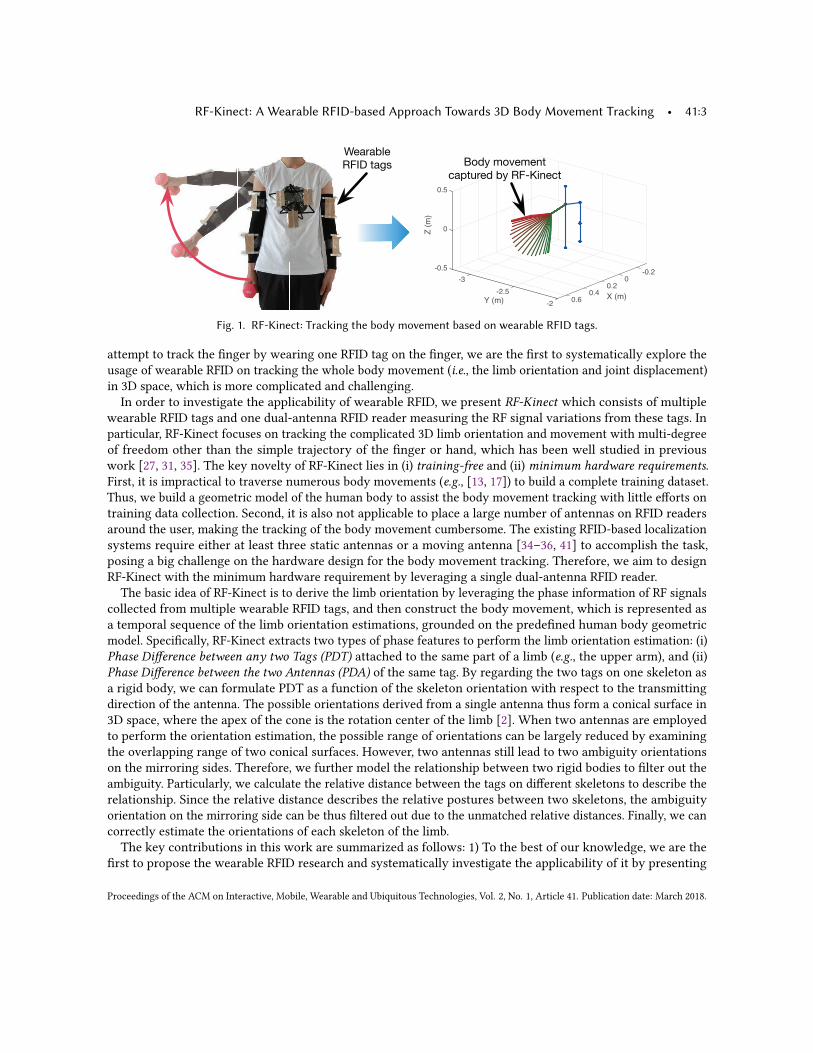
Fig. 2. RF-Kinect illustration of the RFID-based human body movements tracking.
figure by analyzing the RF signals’ reflections through walls and occlusions, thereby accurately locating each partof the human body. Nowadays, as the rapid development of RFID-based localization techniques [28, 34, 41], moresystems are developed to sense human activities based on RFID. Wang et al. [35] recover the moving trace of thetagged finger on a surface plane based on the AoA model. Shangguan et al. [29] tracks the tagged object in the 2Dplane for user feedbacks based on only one antenna. But these methods only work in 2D space by tracking a rigidbody, and thus are not suitable for tracking the complicated movement of the human body. Lin et al. [21] trackthe motion status of the tagball based on the phase variation read from the attached tags. Tagyro [39] estimatesthe orientation of passive objects that have the constant geometric by analyzing the Phase Difference of Arrivalof attached tags. Ding et al. [13] aim to detect the fitness gestures leveraging the Doppler profile extracted fromthe phase trend of RF signals. These RFID-based methods mainly focus on estimating the position/orientation ofone single passive rigid body or recognizing the gestures via pattern matching. However, RF-Kinect is designedto track the whole body movement through a model-based approach, which involves several related rigid bodies(i.e., skeletons) and thus is more challenging for the design of the model-based approach.
3 APPLICATIONS & CHALLENGESIn this section, we first present the application scenario of RF-Kinect, and introduce the preliminaries of trackinghuman body movements using RF signals. We then describe the main challenges of the proposed RF-Kinect.
3.1 RF-Kinect Application ScenarioThe wireless information gathered from wearable RFID tags opens a new research opportunity for developinggesture recognition systems and supporting related applications. RF-Kinect is such a system aiming to trackhuman body movements based on the RF signals emitted from the wearable RFID tags attached to the humanbody. Taking the Virtual reality (VR) gaming as one example, we can utilize RF-Kinect to recognize the usergestures during the game, in the meanwhile, RF-Kinect can also identify specific users based on the wearabletag IDs at any time. Therefore, RF-Kinect can easily support multi-player games by identifying the users fromthe tag IDs and automatically reload the gaming process for each user from the tag ID. In the contrast, eventraditional vision-based approaches can provide good accuracy in the games, they usually need to manuallyconfigure for different users and may also suffer from the interference of surrounding people, leading to baduser experience. Personal fitness, as another example, could also rely on RF-Kinect to associate the recognizedactivities with the subject for the fitness monitoring. Due to the energy harvesting capability of the wearableRFID tags from backscattered signal, RF-Kinect could operate for a long term without the battery supply issues
Proceedings of the ACM on Interactive, Mobile, Wearable and Ubiquitous Technologies, Vol. 2, No. 1, Article 41. Publication date: March 2018.
41:6 • C. Wang et al.
RFID antennaRFID Tag
x
y
z
x
y z
Antenna pattern
of the dipole tag
(a) Experiment deployment of examining the influence of tag orientation
Rotation angle (°)-90 -45 0 45 90
Ph
ase
val
ue
(rad
ian
)
0
2
4
6
8
10XYZ
(b) Phase value increases according to thechange of tag orientation
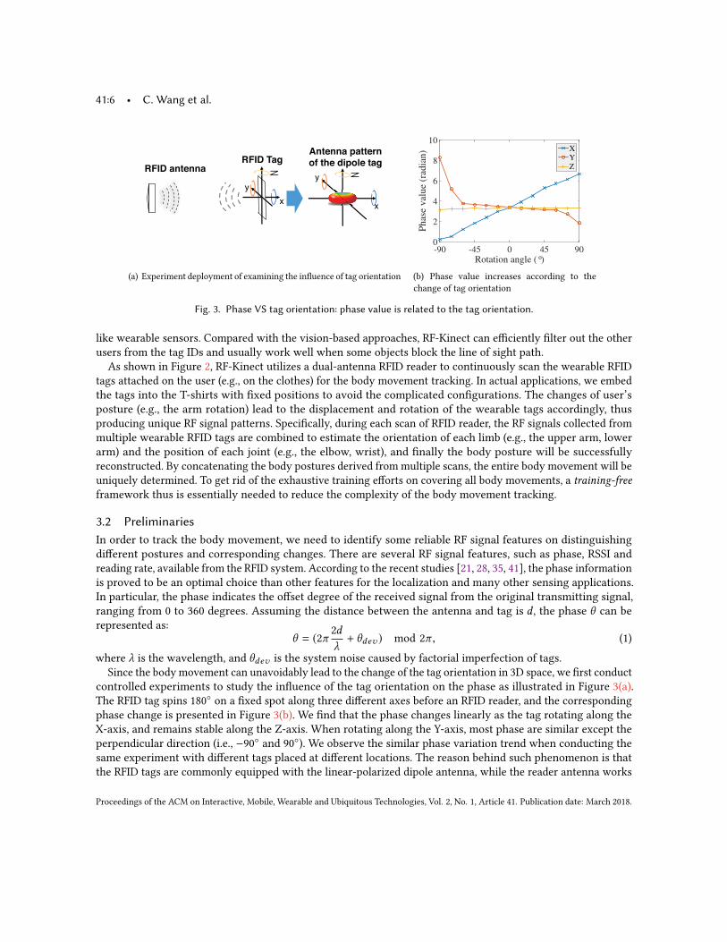
Fig. 3. Phase VS tag orientation: phase value is related to the tag orientation.
like wearable sensors. Compared with the vision-based approaches, RF-Kinect can efficiently filter out the otherusers from the tag IDs and usually work well when some objects block the line of sight path.
As shown in Figure 2, RF-Kinect utilizes a dual-antenna RFID reader to continuously scan the wearable RFIDtags attached on the user (e.g., on the clothes) for the body movement tracking. In actual applications, we embedthe tags into the T-shirts with fixed positions to avoid the complicated configurations. The changes of user’sposture (e.g., the arm rotation) lead to the displacement and rotation of the wearable tags accordingly, thusproducing unique RF signal patterns. Specifically, during each scan of RFID reader, the RF signals collected frommultiple wearable RFID tags are combined to estimate the orientation of each limb (e.g., the upper arm, lowerarm) and the position of each joint (e.g., the elbow, wrist), and finally the body posture will be successfullyreconstructed. By concatenating the body postures derived from multiple scans, the entire body movement will beuniquely determined. To get rid of the exhaustive training efforts on covering all body movements, a training-freeframework thus is essentially needed to reduce the complexity of the body movement tracking.
3.2 PreliminariesIn order to track the body movement, we need to identify some reliable RF signal features on distinguishingdifferent postures and corresponding changes. There are several RF signal features, such as phase, RSSI andreading rate, available from the RFID system. According to the recent studies [21, 28, 35, 41], the phase informationis proved to be an optimal choice than other features for the localization and many other sensing applications.In particular, the phase indicates the offset degree of the received signal from the original transmitting signal,ranging from 0 to 360 degrees. Assuming the distance between the antenna and tag is d , the phase θ can berepresented as:
θ = (2π2dλ+ θdev ) mod 2π , (1)
where λ is the wavelength, and θdev is the system noise caused by factorial imperfection of tags.Since the body movement can unavoidably lead to the change of the tag orientation in 3D space, we first conduct
controlled experiments to study the influence of the tag orientation on the phase as illustrated in Figure 3(a).The RFID tag spins 180◦ on a fixed spot along three different axes before an RFID reader, and the correspondingphase change is presented in Figure 3(b). We find that the phase changes linearly as the tag rotating along theX-axis, and remains stable along the Z-axis. When rotating along the Y-axis, most phase are similar except theperpendicular direction (i.e., −90◦ and 90◦). We observe the similar phase variation trend when conducting thesame experiment with different tags placed at different locations. The reason behind such phenomenon is thatthe RFID tags are commonly equipped with the linear-polarized dipole antenna, while the reader antenna works
Proceedings of the ACM on Interactive, Mobile, Wearable and Ubiquitous Technologies, Vol. 2, No. 1, Article 41. Publication date: March 2018.
RF-Kinect: A Wearable RFID-based Approach Towards 3D Body Movement Tracking • 41:7
!"#$
%&'(&&%
!"#$
)%*+
(a) A user stretches the arm forward with two tags at-tached on the arm
Time (s)
0 1 2 3 4 5 6
PD
T (
rad
ian
)
1
1.5
2
2.5
3
3.5
4
PDT
peak
(b) PDT trend when the user stretches the arm forward
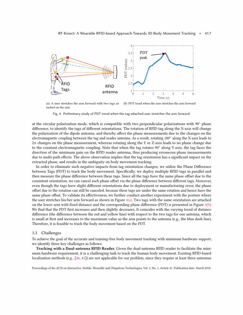
Fig. 4. Preliminary study of PDT trend when the tag-attached user stretches the arm forward.
at the circular polarization mode, which is compatible with two perpendicular polarizations with 90◦ phasedifference, to identify the tags of different orientations. The rotation of RFID tag along the X-axis will changethe polarization of the dipole antenna, and thereby affect the phase measurements due to the changes on theelectromagnetic coupling between the tag and reader antenna. As a result, rotating 180◦ along the X-axis leads to2π changes on the phase measurement, whereas rotating along the Y or Z-axis leads to no phase change dueto the constant electromagnetic coupling. Note that when the tag rotates 90◦ along Y-axis, the tag faces thedirection of the minimum gain on the RFID reader antenna, thus producing erroneous phase measurementsdue to multi-path effects. The above observation implies that the tag orientation has a significant impact on theextracted phase, and results in the ambiguity on body movement tracking.In order to eliminate such negative impacts from tag orientation changes, we utilize the Phase Difference
between Tags (PDT) to track the body movement. Specifically, we deploy multiple RFID tags in parallel andthen measure the phase difference between these tags. Since all the tags have the same phase offset due to theconsistent orientation, we can cancel such phase offset via the phase difference between different tags. Moreover,even though the tags have slight different orientations due to deployment or manufacturing error, the phaseoffset due to the rotation can still be canceled, because these tags are under the same rotation and hence have thesame phase offset. To validate its effectiveness, we further conduct another experiment with the posture wherethe user stretches his/her arm forward as shown in Figure 4(a). Two tags with the same orientation are attachedon the lower arm with fixed distance and the corresponding phase difference (PDT) is presented in Figure 4(b).We find that the PDT first increases and then slightly decreases. It coincides with the varying trend of distancedifference (the difference between the red and yellow line) with respect to the two tags for one antenna, whichis small at first and increases to the maximum value as the arm points to the antenna (e.g., the blue dash line).Therefore, it is feasible to track the body movement based on the PDT.
3.3 ChallengesTo achieve the goal of the accurate and training-free body movement tracking with minimum hardware support,we identify three key challenges as follows:
Tracking with a Dual-antenna RFID Reader. Given the dual-antenna RFID reader to facilitate the mini-mum hardware requirement, it is a challenging task to track the human body movement. Existing RFID-basedlocalization methods (e.g., [26, 41]) are not applicable for our problem, since they require at least three antennas
Proceedings of the ACM on Interactive, Mobile, Wearable and Ubiquitous Technologies, Vol. 2, No. 1, Article 41. Publication date: March 2018.
41:8 • C. Wang et al.
or moving antennas to locate a target tag in 2D environment. Other related studies such as [27] and [29] canlocate a tagged object with two antennas or only one antenna, but they only work in 2D plane and they onlytrack one object by attaching one or more tags on it. For the complex body movement in 3D space, it is notapplicable to the motion tracking in our application scenario. Thus, a dual-antenna-based solution needs to beproposed to facilitate the 3D body movement tracking.Imperfect Phase Measurements. Unlike previous RFID-based localization studies [35, 41] that track the tag
movement in 2D space, our work aims to achieve a more challenging goal, i.e., tracking the movement in 3Dspace. So it poses even higher requirements on the phase measurements. There are multiple factors that mayaffect the uniqueness and accuracy of phase measurements related to the body movement. According to ourpreliminary study, the phase change of the RF signal is determined by both the tag-antenna distance and the tagorientation. Moreover, both the water-rich human body and the muscle deformation during the body movementmay also affect the phase measurements from RF signals. All the above factors together make it much harder totrack the human body movement in 3D space leveraging the phase information in RF-signals.Training-free Body Movement Tracking. Existing studies on gesture tracking usually spend significant
efforts on training the classification model by asking the users to perform each specific gesture multiple times [13,25]. However, the number of gestures that can be recognized highly relies on the size of the training set, so thescalability to unknown gestures is greatly thwarted. Some other methods [29, 31, 35] are designed to recover thetrace of a rigid body (e.g., the finger and box) from the signal models, but they are not suitable for the complexhuman body, which consists of several rigid bodies. In order to identify diverse gestures or postures flexibly ofthe complex human body, it is critical to develop a body movement tracking system that does not rely on anytraining dataset.
4 SYSTEM DESIGNIn this section, we first introduce the architecture of our RF-Kinect system, and then present the building modulesof RF-Kinect for tracking the 3D body movement.
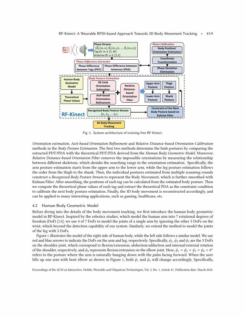
4.1 System ArchitectureThe basic idea of RF-Kinect is to derive the body posture in each scanning round by analyzing the RF signalsfrom the wearable RFID tags attached on the limbs and chest, and then reconstruct the body movement from aseries of body postures in consecutive scans. Figure 5 illustrates the architecture of RF-Kinect. We first extractthe phase information ofM RFID tags from two antennas in consecutive scanning rounds as Phase Stream, whereall the attached tags are read in each scanning round. Then the system is initialized by requiring the user tostand still with his/her arms hanging down naturally. As a perfect rigid object, the tags on the chest enable BodyPosition/Orientation Estimation module to determine the position and facing orientation of the user relative to theantennas based on a model-based approach in the previous work (e.g., [21]). Then, Coordinate Transformationmodule converts the relative positions of the antennas into the Skeleton Coordinate System (SCS), which isdefined based on the human body geometric structure in Section 4.2, so that the coordinates of both the tags andantennas could be expressed properly. Based on the coordinates of the antennas and tags attached on the userbody when the user stands still, the theoretical phase value of each tag is calculated from Eq. (1). Phase DeviationElimination module then computes the phase offset between the theoretical and the measured phase value, whichis used to eliminate the phase deviation in the following biased phase stream.
After the above preprocessing, Phase Difference Extraction module extracts two phase related features from theRF signal measurements in each scanning round: (i) Phase Difference between any two Tags (PDT) attached tothe same part of a limb (e.g., the upper arm), and (ii) Phase Difference between the two Antennas (PDA) of thesame tag. The two phase related features are then utilized to estimate the limb postures based on the 3D Limb
Proceedings of the ACM on Interactive, Mobile, Wearable and Ubiquitous Technologies, Vol. 2, No. 1, Article 41. Publication date: March 2018.
RF-Kinect: A Wearable RFID-based Approach Towards 3D Body Movement Tracking • 41:9
!"#$ %"&'('")*
+,'-)(.('") /&('0.('")
123!"#$ 4"5-0-)(
6,.78')9
%:.&- 2-5'.('")
/;'0').('")
!"#$% &'((%)%*+% ,-.)#+.'/*
%:.&- 2'<<-,-)7-
=-(>--) 6.9& ?%26@
%:.&- 2'<<-,-)7- =-(>--)
A)(-)).& ?%2A@
B-7"9)'C-# !"#$ %"&(D,- E(,-.0
!"#$ "%$ & $ "'(
F")&(,.')(3"<3(:-3G-H(3
!"#$3%"&(D,-3=.&-#3")3
I.;0.) J';(-,
!"#$%01#2'3)#.'/*%:.&- E(,-.0
!)#* +$, $ )%* +$, $& $ )'- .+$ ,/(
!"# $%&+ 0 1$2
'()*((" $%& , 0 31$45
A"AK=.&-#
+,'-)(.('")
B-<')-0-)(
LMM-, A,0
%"&(D,-
N">-, A,0
%"&(D,-
4/56 !/$.7)% ,$.'8#.'/*
BJKI')-7(
OD0.) !"#$
P-"0-(,'73
4"#-;
F"",#').(-
6,.)&<",0.('")
6:'9:
%"&(D,-
E:.)8
%"&(D,-6:-",-('7.;
%:.&- Q.;D-&
12 N'0=
+,'-)(.('")
/&('0.('")
B-;.('5-
2'&(.)7-K
=.&-#
+,'-)(.('")
J';(-,
Fig. 5. System architecture of training-free RF-Kinect.
Orientation estimation, AoA-based Orientation Refinement and Relative Distance-based Orientation Calibrationmethods in the Body Posture Estimation. The first two methods determine the limb postures by comparing theextracted PDT/PDA with the theoretical PDT/PDA derived from the Human Body Geometric Model. Moreover,Relative Distance-based Orientation Filter removes the impossible orientations by measuring the relationshipbetween different skeletons, which shrinks the searching range in the orientation estimation. Specifically, thearm posture estimation starts from the upper arm to the lower arm, while the leg posture estimation followsthe order from the thigh to the shank. Then, the individual postures estimated from multiple scanning roundsconstruct a Recognized Body Posture Stream to represent the Body Movement, which is further smoothed withKalman Filter. After smoothing, the positions of each tag can be calculated from the estimated body posture. Thenwe compute the theoretical phase values of each tag and extract the theoretical PDA as the constraint conditionto calibrate the next body posture estimation. Finally, the 3D body movement is reconstructed accordingly, andcan be applied to many interesting applications, such as gaming, healthcare, etc.
4.2 Human Body Geometric ModelBefore diving into the details of the body movement tracking, we first introduce the human body geometricmodel in RF-Kinect. Inspired by the robotics studies, which model the human arm into 7 rotational degrees offreedom (DoF) [24], we use 4 of 7 DoFs to model the joints of a single arm by ignoring the other 3 DoFs on thewrist, which beyond the detection capability of our system. Similarly, we extend the method to model the jointsof the leg with 3 DoFs.
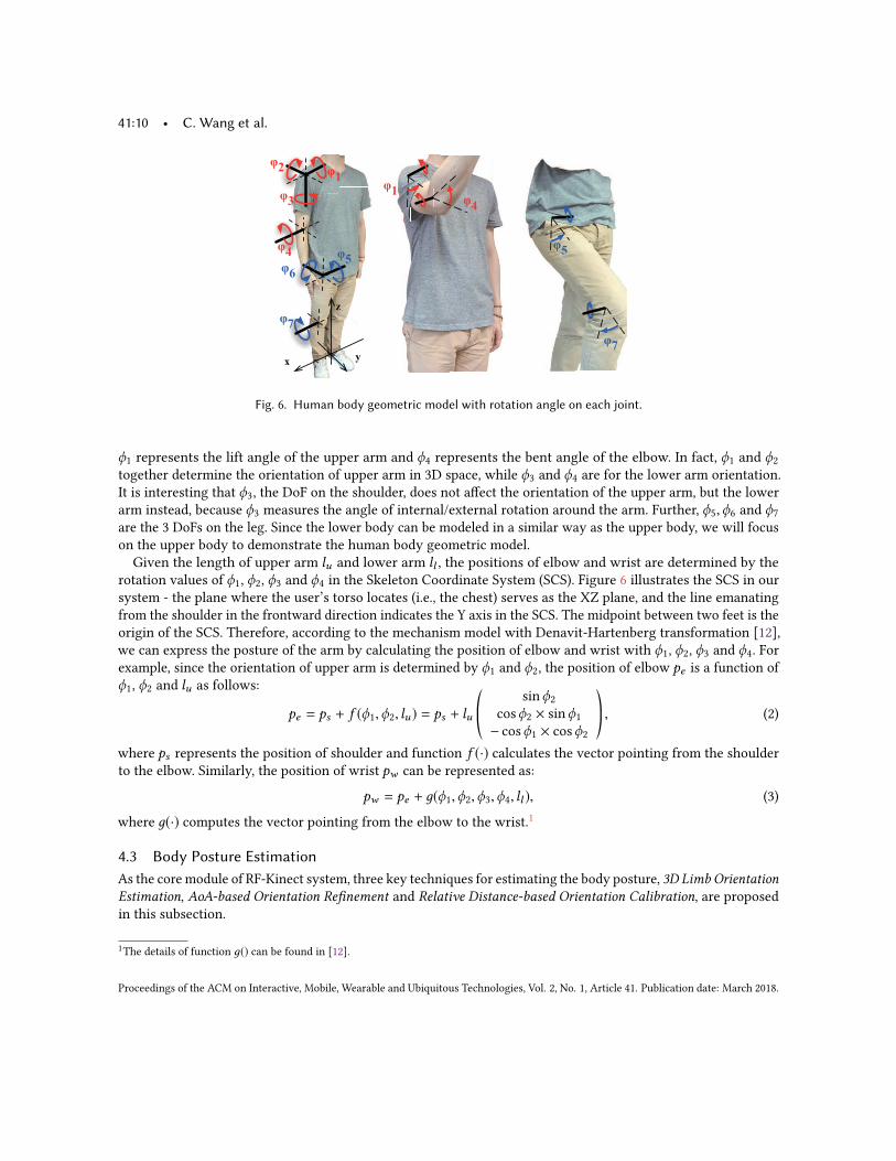
Figure 6 illustrates the model of the right side of human body, while the left side follows a similar model. We usered and blue arrows to indicate the DoFs on the arm and leg, respectively. Specifically, ϕ1, ϕ2 and ϕ3 are the 3 DoFson the shoulder joint, which correspond to flexion/extension, abduction/adduction and internal/external rotationof the shoulder, respectively, and ϕ4 represents flexion/extension on the elbow joint. Here, ϕ1 = ϕ2 = ϕ3 = ϕ4 = 0◦refers to the posture where the arm is naturally hanging down with the palm facing forward. When the userlifts up one arm with bent elbow as shown in Figure 6, both ϕ1 and ϕ4 will change accordingly. Specifically,
Proceedings of the ACM on Interactive, Mobile, Wearable and Ubiquitous Technologies, Vol. 2, No. 1, Article 41. Publication date: March 2018.
41:10 • C. Wang et al.
! "
#
$%
&
'
$
'
(
)
*
(
*
Fig. 6. Human body geometric model with rotation angle on each joint.
ϕ1 represents the lift angle of the upper arm and ϕ4 represents the bent angle of the elbow. In fact, ϕ1 and ϕ2together determine the orientation of upper arm in 3D space, while ϕ3 and ϕ4 are for the lower arm orientation.It is interesting that ϕ3, the DoF on the shoulder, does not affect the orientation of the upper arm, but the lowerarm instead, because ϕ3 measures the angle of internal/external rotation around the arm. Further, ϕ5,ϕ6 and ϕ7are the 3 DoFs on the leg. Since the lower body can be modeled in a similar way as the upper body, we will focuson the upper body to demonstrate the human body geometric model.Given the length of upper arm lu and lower arm ll , the positions of elbow and wrist are determined by the
rotation values of ϕ1, ϕ2, ϕ3 and ϕ4 in the Skeleton Coordinate System (SCS). Figure 6 illustrates the SCS in oursystem - the plane where the user’s torso locates (i.e., the chest) serves as the XZ plane, and the line emanatingfrom the shoulder in the frontward direction indicates the Y axis in the SCS. The midpoint between two feet is theorigin of the SCS. Therefore, according to the mechanism model with Denavit-Hartenberg transformation [12],we can express the posture of the arm by calculating the position of elbow and wrist with ϕ1, ϕ2, ϕ3 and ϕ4. Forexample, since the orientation of upper arm is determined by ϕ1 and ϕ2, the position of elbow pe is a function ofϕ1, ϕ2 and lu as follows:
pe = ps + f (ϕ1,ϕ2, lu ) = ps + lu©«
sinϕ2cosϕ2 × sinϕ1− cosϕ1 × cosϕ2
ª®¬ , (2)
where ps represents the position of shoulder and function f (·) calculates the vector pointing from the shoulderto the elbow. Similarly, the position of wrist pw can be represented as:
pw = pe + д(ϕ1,ϕ2,ϕ3,ϕ4, ll ), (3)
where д(·) computes the vector pointing from the elbow to the wrist.1
4.3 Body Posture EstimationAs the core module of RF-Kinect system, three key techniques for estimating the body posture, 3D Limb OrientationEstimation, AoA-based Orientation Refinement and Relative Distance-based Orientation Calibration, are proposedin this subsection.
1The details of function д() can be found in [12].
Proceedings of the ACM on Interactive, Mobile, Wearable and Ubiquitous Technologies, Vol. 2, No. 1, Article 41. Publication date: March 2018.
RF-Kinect: A Wearable RFID-based Approach Towards 3D Body Movement Tracking • 41:11
!
"#$%& '(
Antenna 'RFID
tags
Collinear direction
Rotation
center O")*
+,-*&,-.&,
-.&/-*&/
(a) Model of 3D orientation estimation
Conical surface from
one antenna
Conical surface from
another antenna
Limb orientation
Mirroring ambiguity
(b) Limb estimation via conical surfaces
Deviation angle (°)0 30 60 90P
has
e d
iffe
ren
ce P
DT
(ra
dia
n)
-5
-4
-3
-2
-1
0
1
Theoretical PDT |AO|=150∼300cmMeasured PDT |AO|=150∼300cm
(c) PDT results with different distances betweentag and antenna
Deviation angle (°)0 30 60 90P
has
e d
iffe
ren
ce P
DT
(ra
dia
n)
-5
-4
-3
-2
-1
0
1
Theoretical PDT |T_rO|=0∼10cmMeasured PDT |T_rO|=0∼10cm
(d) PDT results with different rotation centers
Fig. 7. Basic idea of estimating 3D orientation and its experimental results.
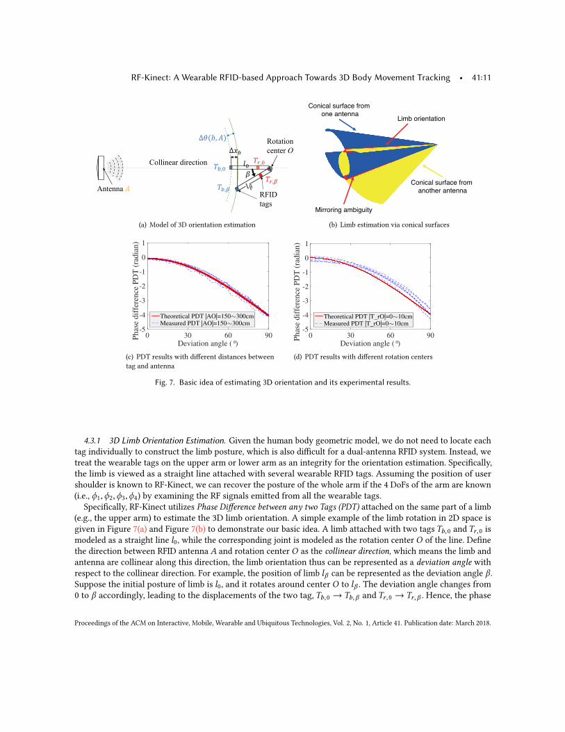
4.3.1 3D Limb Orientation Estimation. Given the human body geometric model, we do not need to locate eachtag individually to construct the limb posture, which is also difficult for a dual-antenna RFID system. Instead, wetreat the wearable tags on the upper arm or lower arm as an integrity for the orientation estimation. Specifically,the limb is viewed as a straight line attached with several wearable RFID tags. Assuming the position of usershoulder is known to RF-Kinect, we can recover the posture of the whole arm if the 4 DoFs of the arm are known(i.e., ϕ1,ϕ2,ϕ3,ϕ4) by examining the RF signals emitted from all the wearable tags.
Specifically, RF-Kinect utilizes Phase Difference between any two Tags (PDT) attached on the same part of a limb(e.g., the upper arm) to estimate the 3D limb orientation. A simple example of the limb rotation in 2D space isgiven in Figure 7(a) and Figure 7(b) to demonstrate our basic idea. A limb attached with two tags Tb,0 and Tr,0 ismodeled as a straight line l0, while the corresponding joint is modeled as the rotation center O of the line. Definethe direction between RFID antenna A and rotation center O as the collinear direction, which means the limb andantenna are collinear along this direction, the limb orientation thus can be represented as a deviation angle withrespect to the collinear direction. For example, the position of limb lβ can be represented as the deviation angle β .Suppose the initial posture of limb is l0, and it rotates around center O to lβ . The deviation angle changes from0 to β accordingly, leading to the displacements of the two tag, Tb,0 → Tb,β and Tr,0 → Tr,β . Hence, the phase
Proceedings of the ACM on Interactive, Mobile, Wearable and Ubiquitous Technologies, Vol. 2, No. 1, Article 41. Publication date: March 2018.
41:12 • C. Wang et al.
difference between the two positions (i.e., l0 and lβ ) at antenna A is derived based on Eq. (1) as:
∆θ (b,A) = θβ (b,A) − θ0(b,A) = 4π|ATb,β | − |ATb,0 |
λ+ ω(β) mod 2π ,
∆θ (r ,A) = θβ (r ,A) − θ0(r ,A) = 4π|ATr,β | − |ATr,0 |
λ+ ω(β) mod 2π ,
(4)
where | · | measures the Euclidean distance and ω(β) calculates the phase offset due to the change of the tagorientation. The phase deviation θdev of each tag could be canceled during the above calculation. Theoretically, ifthe distance between rotation center O and RFID reader antenna A, |AO |, is much larger than |Tb,0O |, |ATb,β | −|ATb,0 | is approximated to the distance change ∆xb along the collinear direction as follows:
∆xb = |Tb,0O |(1 − cos β) ≈ |ATb,β | − |ATb,0 | = (∆θ (b,A) − ω(β)
2π+ k)
λ
2where k = 0,±1, · · · . (5)
Similarly, we also derive the change on the distance between the red tag ∆xr and antenna A as:
∆xr = |Tr,0O |(1 − cos β) ≈ |ATr,β | − |ATr,0 | = (∆θ (r ,A) − ω(β)
2π+ k)
λ
2where k = 0,±1, · · · . (6)
To remove the phase offset resulted from the changes of tag orientation ω(β), we combine the phase changeswith respect to the two tags as:
|Tb,0Tr,0 |(1 − cos β) ≈ (∆θ (b,A) − ∆θ (r ,A)
2π+ k)
λ
2where k = 0,±1, · · · . (7)
Therefore, given the distance between the two tags |Tb,0Tr,0 |, deviation angle β could be obtained based on thePDT ∆θ (b,A) − ∆θ (r ,A).Once the deviation angle β with respect to one RFID antenna is obtained, the possible postures of the limb
form a conical surface around the collinear direction, where the apex of the cone is rotation center O . Figure 7(b)presents a sample for the estimation. Given the deviation angles with respect to two antennas located at twodifferent positions, we can determine the posture of the limbs by finding the common places of the two conicalsurfaces. Since we use only two antennas, there is an ambiguity on the mirror side with respect to the linebetween the two antennas.We validate the feasibility of using PDT for the deviation angle estimation via the following two basic
experiments. 1) In the first experiment, we vary the distance of |AO | from 150cm to 300cm, and in the meanwhilespin the line l0 from 0◦ to 90◦ as shown Figure 7(a). The red tag is always fixed at O (|Tr,0O | = 0) during themovement. The actual and theoretical PDT variations of different AO distances presented in Figure 7(c) areclosely overlapping. It indicates that the estimation of the deviation angle via PDT is independent of the distancebetween the tag and antenna. 2) For the second experiment, before spinning line l0 around O in a similar way asabove, we change the location of rotation center O by varying the distance |Tr,0O | from 0cm to 10cm. As shownin Figure 7(d), the actual and theoretical PDT variations are still similar to each other, so the effectiveness of usingPDT for the limb orientation estimation is verified. In addition, since all the tags on the same part of limb (i.e.,the upper arm or lower arm) have the same orientation, the phase offset due to the tag orientation is canceledthrough the PDT calculation and will not affect the final estimation of the deviation angle.
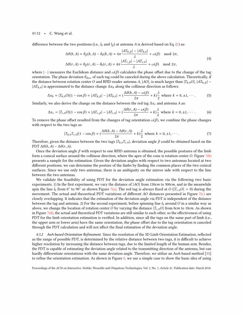
4.3.2 AoA-based Orientation Refinement. Since the resolution of the 3D Limb Orientation Estimation, reflectedas the range of possible PDT, is determined by the relative distance between two tags, it is difficult to achievehigher resolution by increasing the distance between tags, due to the limited length of the human arm. Besides,the PDT is capable of estimating the deviation angle related to the transmitting direction of the antenna, but canhardly differentiate orientations with the same deviation angle. Therefore, we utilize an AoA-based method [35]to refine the orientation estimation. As shown in Figure 8, we use a simple case to show the basic idea of using
Proceedings of the ACM on Interactive, Mobile, Wearable and Ubiquitous Technologies, Vol. 2, No. 1, Article 41. Publication date: March 2018.
RF-Kinect: A Wearable RFID-based Approach Towards 3D Body Movement Tracking • 41:13
RFID
tags
Antenna !"
Angle of
Arrival
Antenna !#
$%
$&
'%
'&
()*)+
(a) AoA model with two RFID tags and two antennas
!"
!#
$%$&
'&'%
Estimated 3D limb
orientation after AoA
refinement.
Estimated 3D limb
orientation
(b) Refinement based on AoA
Fig. 8. AoA-based Orientation Refinement.
the Phase Difference between the two Antennas (PDA) of the same tag to determine the Angle of Arrival (AoA) ofeach tag and then refine the limb orientation. The limb is also modeled as a line segment with two tags Tb and Trindicating two end points, and the corresponding AoAs of the received signals from the two tags are αb and αr ,respectively. Taking blue tag Tb as an example, when two antennas A1 and A2 on RFID reader interrogate the tag,we could obtain two phase values θ (b,A1) and θ (b,A2) from tag Tb . So the PDA is represented as:
∆θ (b) = θ (b,A1) − θ (b,A2). (8)
Since the phase value of the RFID tag is linearly proportional to the distance between the antenna and tag, thedistance difference, ∆db , from tag Tb to two antennas on RFID reader could be obtained from the PDA as:
∆db = |A1Tb | − |A2Tb | =λ
2(∆θ (b)
2π+ k), where k = 0,±1, · · · . (9)
Then a half hyperbolas is generated based on ∆db , which indicates the AoA of tag Tb . According to the analysisin [35], the distance difference ∆db with respect to two antennas can be approximated as |A1A2 | cosαb , so wecan further derive angle αb as:
cosαb =λ
2|A1A2 |(∆θ (b)
2π+ k), where k = 0,±1, · · · , (10)
where αb indicates the angle of the asymptotic line of the hyperbolas. Similarly, AoA αr for tagTr can be obtainedin the same way as described above, and obviously αr is larger than αb . Given the AoA estimation of the attachedtags, we can refine the estimated 3D limb orientation by searching for the intersection between the AoA directions(i.e., αr and αb ) and the estimated 3D limb orientation (i.e., β). Figure 8(b) illustrates the refined 3D limb orientationestimation based on the example given in Figure 7(b). The green line shown in Figure 8(b) indicates the refinedlimb orientation, which is determined by the intersections.
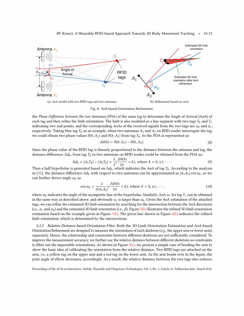
4.3.3 Relative Distance-based Orientation Filter. Both the 3D Limb Orientation Estimation and AoA-basedOrientation Refinement are designed to measure the orientation of each skeleton (e.g., the upper arm or lower arm),separately. Hence, the relationship and constraints between different skeletons are not sufficiently considered. Toimprove the measurement accuracy, we further use the relative distance between different skeletons as constraintsto filter out the impossible orientations. As shown in Figure 9(a), we present a simple case of bending the arm toshow the basic idea of calibrating the orientation from the relative distance. Two RFID tags are attached on thearm, i.e., a yellow tag on the upper arm and a red tag on the lower arm. As the arm bends over in the figure, thejoint angle of elbow decreases, accordingly. As a result, the relative distance between the two tags also reduces.
Proceedings of the ACM on Interactive, Mobile, Wearable and Ubiquitous Technologies, Vol. 2, No. 1, Article 41. Publication date: March 2018.
41:14 • C. Wang et al.
Bending the arm
RFID tag
RFID tag
Joint
angle
(a) Orientation calibration of bendingarm
!"
!#
$%
$&
'
(b) Relative distance calculation from the phasechange
Position error (cm)0 20 40 60 80 100
Rel
ativ
e dis
tance
err
or
(cm
)
0
0.5
1
1.5
2
2.5
(c) Accuracy of relative distance
Fig. 9. Relative Distance-based Orientation Calibration.
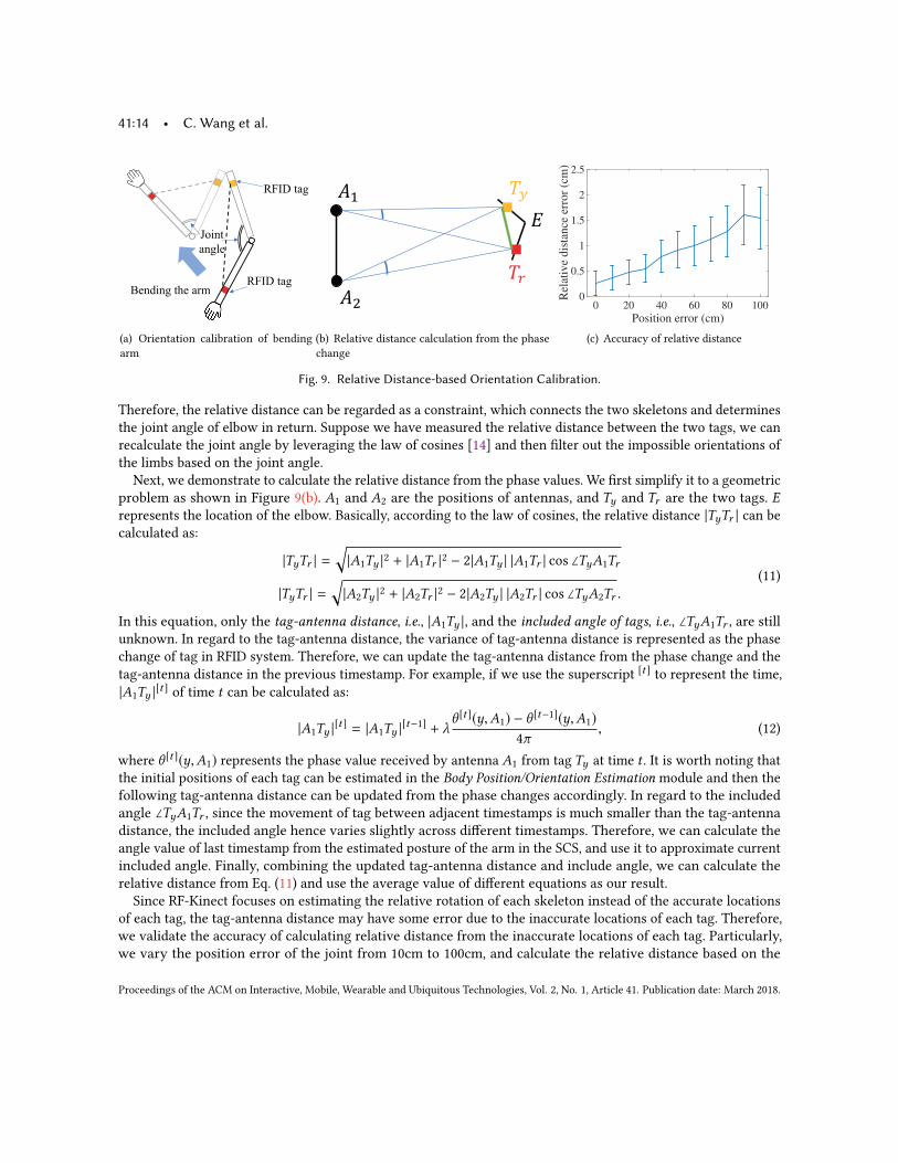
Therefore, the relative distance can be regarded as a constraint, which connects the two skeletons and determinesthe joint angle of elbow in return. Suppose we have measured the relative distance between the two tags, we canrecalculate the joint angle by leveraging the law of cosines [14] and then filter out the impossible orientations ofthe limbs based on the joint angle.
Next, we demonstrate to calculate the relative distance from the phase values. We first simplify it to a geometricproblem as shown in Figure 9(b). A1 and A2 are the positions of antennas, and Ty and Tr are the two tags. Erepresents the location of the elbow. Basically, according to the law of cosines, the relative distance |TyTr | can becalculated as:
|TyTr | =√|A1Ty |2 + |A1Tr |2 − 2|A1Ty | |A1Tr | cos ∠TyA1Tr
|TyTr | =√|A2Ty |2 + |A2Tr |2 − 2|A2Ty | |A2Tr | cos ∠TyA2Tr .
(11)
In this equation, only the tag-antenna distance, i.e., |A1Ty |, and the included angle of tags, i.e., ∠TyA1Tr , are stillunknown. In regard to the tag-antenna distance, the variance of tag-antenna distance is represented as the phasechange of tag in RFID system. Therefore, we can update the tag-antenna distance from the phase change and thetag-antenna distance in the previous timestamp. For example, if we use the superscript [t ] to represent the time,|A1Ty |
[t ] of time t can be calculated as:
|A1Ty |[t ] = |A1Ty |
[t−1] + λθ [t ](y,A1) − θ [t−1](y,A1)
4π, (12)
where θ [t ](y,A1) represents the phase value received by antenna A1 from tag Ty at time t . It is worth noting thatthe initial positions of each tag can be estimated in the Body Position/Orientation Estimation module and then thefollowing tag-antenna distance can be updated from the phase changes accordingly. In regard to the includedangle ∠TyA1Tr , since the movement of tag between adjacent timestamps is much smaller than the tag-antennadistance, the included angle hence varies slightly across different timestamps. Therefore, we can calculate theangle value of last timestamp from the estimated posture of the arm in the SCS, and use it to approximate currentincluded angle. Finally, combining the updated tag-antenna distance and include angle, we can calculate therelative distance from Eq. (11) and use the average value of different equations as our result.Since RF-Kinect focuses on estimating the relative rotation of each skeleton instead of the accurate locations
of each tag, the tag-antenna distance may have some error due to the inaccurate locations of each tag. Therefore,we validate the accuracy of calculating relative distance from the inaccurate locations of each tag. Particularly,we vary the position error of the joint from 10cm to 100cm, and calculate the relative distance based on the
Proceedings of the ACM on Interactive, Mobile, Wearable and Ubiquitous Technologies, Vol. 2, No. 1, Article 41. Publication date: March 2018.
RF-Kinect: A Wearable RFID-based Approach Towards 3D Body Movement Tracking • 41:15
incorrect position when the arm is bending over with random orientations. For each position error, we repeat theexperiments 10, 000 times, and plot the statistic result in Figure 9(c). We find that the error of relative distanceincreases slightly with the position error. However, even though the joint is located 100cm away from its actualposition, the relative distance error is only about 1.5cm. The reason is that when the user is about 2 ∼ 3m awayfrom the antennas, the inaccurate locations of each joint only leads to very small error (< 2◦) of the includedangle of tags. Hence, we can still efficiently measure the relative distance from the inaccurate locations of eachjoint.
5 3D BODY MOVEMENT TRACKINGIn this section, we introduce the workflow for the 3D body movement tracking by leveraging both the proposed3D Limb Orientation Estimation method, AoA-based Orientation Refinement method and Relative Distance-basedOrientation Filter method. In particular, we estimate the orientations of all the limbs in each scanning round,which is represented as the joint rotation angles in the body geometric model. We take the right arm as anexample for illustration unless mentioned otherwise, and it can be easily extended to other limbs for the completebody posture reconstruction. Once the orientation of each limb is determined, they will be concatenated tocomplete the body movement tracking.
5.1 Estimating Orientation of LimbsDue to the physical structural constraints on human body, most of the joints have limited flexibility to behave. Forexample, there is only one Degree of Freedom (DoF) on the elbow (i.e., flexion/extension) and the joint rotationangle ϕ4 must be positive in Figure 6. To quantify the physical structural constraints on joints, we integrate theRange of Motion (RoM), which is presented by ArmTrack [30] based on some medical studies, into the bodygeometric model.We first estimate the orientation of each limb, and decompose the process into two steps: 1) deriving the
orientation of the upper part of one particular limb (e.g., the right upper arm); and 2) deriving the orientationof the lower part (e.g., the right lower arm) with the knowledge of the upper part’s orientation. Without lossof generality, we focus on the upper arm to look into the algorithm flow. The only parameter in estimating theposture of upper arm is the position of shoulder ps , which is supposed to be fixed when the user moves his/herlimbs. Assume we havem tags (m ≥ 2) attached on the upper arm with known distances from the shoulder, i.e.,the distances di,s between the shoulder and the tag i on the upper arm can be measured in advance. Therefore,given the joint rotation angles Φ = ⟨ϕ1,ϕ2⟩ regulated by RoM, the position pi,Φ of tag i can be derived fromEquation (2) as:
pi,Φ = ps + f (ϕ1,ϕ2,di,s ), i = 1, · · · ,m. (13)
Assuming pA1 and pA2 are the positions of antennas on an RFID reader, the theoretical phase captured by antennaAj from tag i is presented as:
θΦ(i, j) = (2π2| |pi,Φ − pAj | |
λ+ ω(Φ)) mod 2π , j = 1, 2, (14)
where | | · | | denotes the Euclidean distance between the two given positions and ω() estimates the phase offsetcaused by the tag orientation. Note we do not consider phase deviations θdev of each tag, since we have removethem in Phase Deviation Elimination module in Section 4.1. Due to the impact of tag orientation, the phasemeasurements can not be directly applied to determine the tag’s location. Therefore, we calculate the phasedifference between tags (PDT) based on the model in Section 4.3.1 for the estimation of limb orientation as:
∆θΦ(i, j) = θΦ(i, j) − θΦ(1, j). (15)
Proceedings of the ACM on Interactive, Mobile, Wearable and Ubiquitous Technologies, Vol. 2, No. 1, Article 41. Publication date: March 2018.
41:16 • C. Wang et al.
Given the measured phases ⟨ ˆθ [t ](1, 1), ˆθ [t ](1, 2), . . . , ˆθ [t ](m, 1), ˆθ [t ](m, 2)⟩ obtained in the round t , we also calculatethe PDT as:
∆ ˆθ [t ](i, j) = ˆθ [t ](i, j) − ˆθ [t ](1, j). (16)Therefore, our mission is to search for the joint rotation angle Φ to minimize the difference between the measuredPDT ∆ ˆθ [t ](i, j) and theoretical PDT ∆θΦ(i, j). We follow Tagoram [41] to define the likelihood function to evaluatethe closeness the two PDTs as:
ProbΦ =m∑i=1
2∑j=1
|eJ(∆θΦ(i, j)−ˆ∆θ [t ](i, j)) |/2m. (17)
The key idea is that if the joint rotation angles Φ are close to the groundtruth, the theoretical PDT ∆θΦ(i, j) will beclose to the measured PDT ˆ∆θ [t ](i, j), meaning ∆θΦ(i, j) −
ˆ∆θ [t ](i, j) ≈ 0. Then, the vector eJ(∆θΦ(i, j)− ˆ∆θ [t ](i, j)) willreach its maximum value, and we can obtain higher probability value on ProbΦ. Otherwise, ∆θΦ(i, j) − ˆ∆θ [t ](i, j)is a random value within [0, 2π ], resulted from the differences between the joint angles Φ and groundtruth. Thevector eJ(∆θΦ(i, j)− ˆ∆θ [t ](i, j)) is thus smaller than the maximum value and the calculated probability ProbΦ has arelatively lower value. Finally, we can correctly estimate the joint rotation angles Φ with the largest likelihood atround t , which indicates the orientation of the upper arm.
5.2 Refining Orientation of Limbs Based on AoA ModelTheoretically the joint rotation angle can be accurately estimated by following the above procedures, however,the existence of phase measurement errors may produce large errors on determining the limb orientation. Theintuitive way to reduce such error is to increase the resolution of PDT, which is closely related to the Euclideandistance between tags. However, due to limited length of human arm, it is difficult to increase the distancebetween tags for more accurate joint rotation angle estimation. So we adopt the AoA model used in RF-IDraw [35]to calibrate the joint rotation angle estimation. The idea is to calculate the AoA of each tag and choose the theappropriate joint rotation angles Φ that ensure the theoretical AoAs of related tags are the most similar as themeasured AoAs.In particular, we first give the theoretical and estimated phase difference between antennas (PDA) of tag i as
follows:∆θΦ(i) = θΦ(i, 2) − θΦ(i, 1);
ˆ∆θ [t ](i) = ˆθ [t ](i, 2) − ˆθ [t ](i, 1),(18)
where ∆θΦ(i) represents the theoretical PDA related to the limb orientation Φ and ˆ∆θ [t ](i) is the measured PDAin round t . Then the likelihood between ∆θΦ(i) and ˆ∆θ [t ](i) is given as follows:
Prob ′Φ = |
m∑i=1
eJ(∆θΦ(i)−ˆ∆θ [t ](i)) |/m. (19)
Therefore, the calibrated estimation of joint rotation angles can be obtained by summing Prob and Prob ′ asfollows:
argmaxΦ
(S), where S = (ProbΦ + Prob′Φ)/2. (20)
Once ϕ1 and ϕ2 are obtained, we calculate the position of elbow pe and estimate the posture of lower armfollowing the similar way as that for upper arm. The only difference is that the position derivation of each tag iin Eq. (13) is replaced as follows for lower arm orientation estimation:
pi,Φ = pe + д(ϕ1,ϕ2,ϕ3,ϕ4,di,e ), i = 1, · · · ,m, (21)
Proceedings of the ACM on Interactive, Mobile, Wearable and Ubiquitous Technologies, Vol. 2, No. 1, Article 41. Publication date: March 2018.
RF-Kinect: A Wearable RFID-based Approach Towards 3D Body Movement Tracking • 41:17
φ1 (°)
-50 0 50 100
φ2 (°)
0
50
100
(a) Probability distribution ProbΦ calculatedfrom PDT
φ1 (°)
-50 0 50 100
φ2 (°)
0
50
100
(b) Probability distribution Prob′Φ calculatedfrom PDA
φ1 (°)
-50 0 50 100
φ2 (°)
0
50
100
0.2
0.4
0.6
0.8
(c) Probability distribution (ProbΦ + Prob′Φ)/2
Fig. 10. An example of probability distribution for the orientation estimation of upper arm.
where di,e indicates the distance between tag i and the elbow. The arm posture thus can be reconstructed byintegrating both the upper and lower arm. Finally, given a series of arm postures over time, Kalman filter isadopted to smooth the estimated joint rotation angles to produce the complete arm movement.
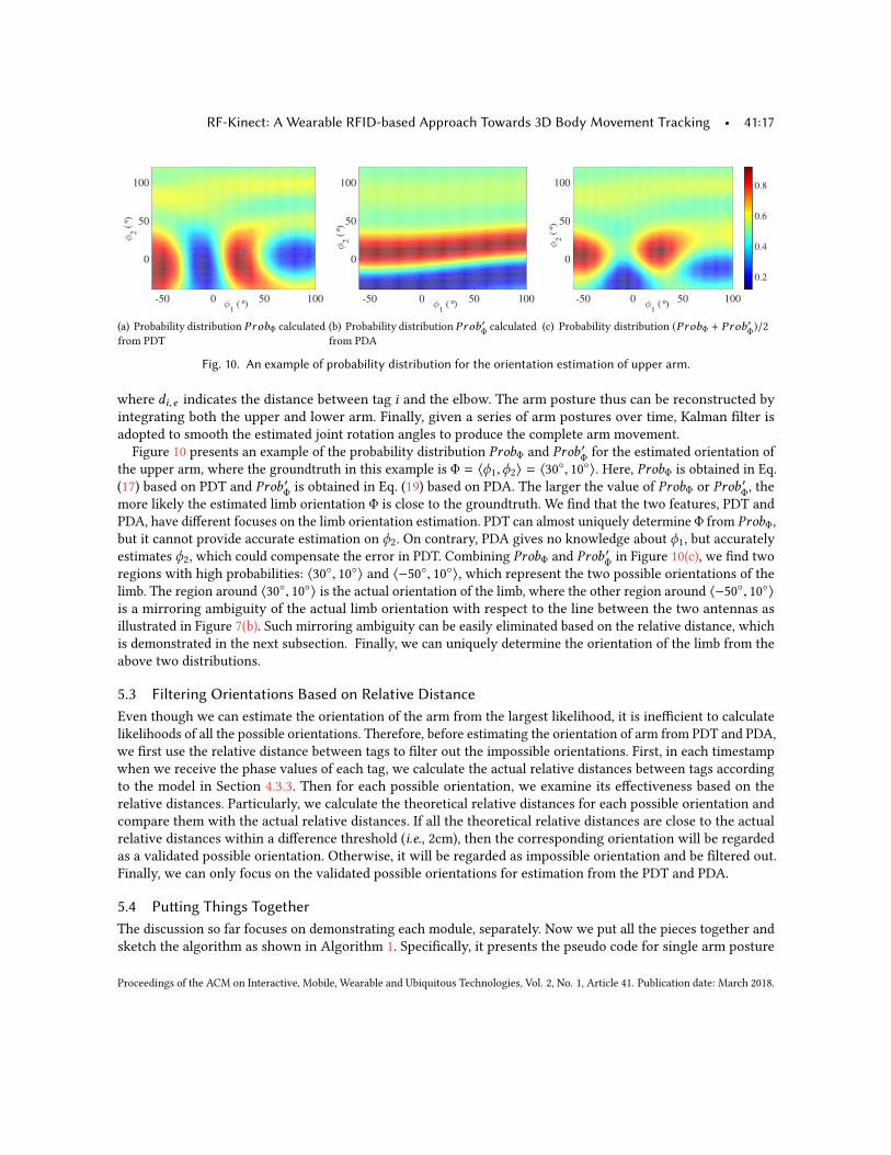
Figure 10 presents an example of the probability distribution ProbΦ and Prob ′Φ for the estimated orientation ofthe upper arm, where the groundtruth in this example is Φ = ⟨ϕ1,ϕ2⟩ = ⟨30◦, 10◦⟩. Here, ProbΦ is obtained in Eq.(17) based on PDT and Prob ′Φ is obtained in Eq. (19) based on PDA. The larger the value of ProbΦ or Prob ′Φ, themore likely the estimated limb orientation Φ is close to the groundtruth. We find that the two features, PDT andPDA, have different focuses on the limb orientation estimation. PDT can almost uniquely determine Φ from ProbΦ,but it cannot provide accurate estimation on ϕ2. On contrary, PDA gives no knowledge about ϕ1, but accuratelyestimates ϕ2, which could compensate the error in PDT. Combining ProbΦ and Prob ′Φ in Figure 10(c), we find tworegions with high probabilities: ⟨30◦, 10◦⟩ and ⟨−50◦, 10◦⟩, which represent the two possible orientations of thelimb. The region around ⟨30◦, 10◦⟩ is the actual orientation of the limb, where the other region around ⟨−50◦, 10◦⟩is a mirroring ambiguity of the actual limb orientation with respect to the line between the two antennas asillustrated in Figure 7(b). Such mirroring ambiguity can be easily eliminated based on the relative distance, whichis demonstrated in the next subsection. Finally, we can uniquely determine the orientation of the limb from theabove two distributions.
5.3 Filtering Orientations Based on Relative DistanceEven though we can estimate the orientation of the arm from the largest likelihood, it is inefficient to calculatelikelihoods of all the possible orientations. Therefore, before estimating the orientation of arm from PDT and PDA,we first use the relative distance between tags to filter out the impossible orientations. First, in each timestampwhen we receive the phase values of each tag, we calculate the actual relative distances between tags accordingto the model in Section 4.3.3. Then for each possible orientation, we examine its effectiveness based on therelative distances. Particularly, we calculate the theoretical relative distances for each possible orientation andcompare them with the actual relative distances. If all the theoretical relative distances are close to the actualrelative distances within a difference threshold (i.e., 2cm), then the corresponding orientation will be regardedas a validated possible orientation. Otherwise, it will be regarded as impossible orientation and be filtered out.Finally, we can only focus on the validated possible orientations for estimation from the PDT and PDA.
5.4 Putting Things TogetherThe discussion so far focuses on demonstrating each module, separately. Now we put all the pieces together andsketch the algorithm as shown in Algorithm 1. Specifically, it presents the pseudo code for single arm posture
Proceedings of the ACM on Interactive, Mobile, Wearable and Ubiquitous Technologies, Vol. 2, No. 1, Article 41. Publication date: March 2018.
41:18 • C. Wang et al.
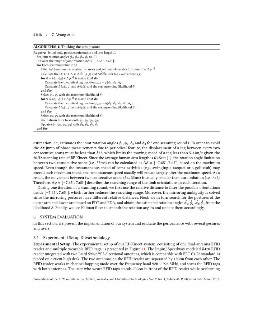
ALGORITHM 1: Tracking the arm postureRequire: Initial body position/orientation and arm length leSet joint rotation angles ϕ1, ϕ2, ϕ3, ϕ4 to 0◦;Initialize the range of joint rotation ∆ϕ = [−7.65◦, 7.65◦];for Each scanning round t do
Filter ∆ϕ based on the relative distances and get possible angles for round t as ∆ϕ[t ]
Calculate the PDT/PDA as ˆ∆θ [t ](i, j) and ˆ∆θ [t ](i) for tag i and antenna j ;for Φ = (ϕ1, ϕ2) + ∆ϕ[t ] is inside RoM do
Calculate the theoretical tag position pi,Φ = f (ϕ1, ϕ2, di );Calculate ∆θΦ(i, j) and ∆θΦ(i) and the corresponding likelihood S ;
end forSelect ϕ̂1, ϕ̂2 with the maximum likelihood S ;for Φ = (ϕ3, ϕ4) + ∆ϕ[t ] is inside RoM do
Calculate the theoretical tag position pi,Φ = д(ϕ̂1, ϕ̂2, ϕ3, ϕ4, di );Calculate ∆θΦ(i, j) and ∆θΦ(i) and the corresponding likelihood S ;
end forSelect ϕ̂3, ϕ̂4 with the maximum likelihood S ;Use Kalman filter to smooth ϕ̂1, ϕ̂2, ϕ̂3, ϕ̂4;Update (ϕ1, ϕ2, ϕ3, ϕ4) with ϕ̂1, ϕ̂2, ϕ̂3, ϕ̂4;
end for
estimation, i.e., estimates the joint rotation angles ϕ1,ϕ2,ϕ3 and ϕ4 for one scanning round t . In order to avoidthe 2π jump of phase measurements due to periodical feature, the displacement of a tag between every twoconsecutive scans must be less than λ/2, which limits the moving speed of a tag less than 5.33m/s given the30Hz scanning rate of RF-Kinect. Since the average human arm length is 63.5cm [1], the rotation angle limitationbetween two consecutive scans (i.e., 33ms) can be calculated as ∆ϕ = [−7.65◦, 7.65◦] based on the maximumspeed. Even though the instantaneous speed of some activities (e.g., swinging a racquet or a golf club) mayexceed such maximum speed, the instantaneous speed usually will reduce largely after the maximum speed. As aresult, the movement between two consecutive scans (i.e., 33ms) is usually smaller than our limitation (i.e., λ/2).Therefore, ∆ϕ = [−7.65◦, 7.65◦] describes the searching range of the limb orientations in each iteration.
During one iteration of a scanning round, we first use the relative distance to filter the possible orientationsinside [−7.65◦, 7.65◦], which further reduces the searching range. Moreover, the mirroring ambiguity is solvedsince the mirroring postures have different relative distances. Next, we in turn search for the postures of theupper arm and lower arm based on PDT and PDA, and obtain the estimated rotation angles ϕ̂1, ϕ̂2, ϕ̂3, ϕ̂4 from thelikelihood S . Finally, we use Kalman filter to smooth the rotation angles and update them accordingly.
6 SYSTEM EVALUATIONIn this section, we present the implementation of our system and evaluate the performance with several gesturesand users.
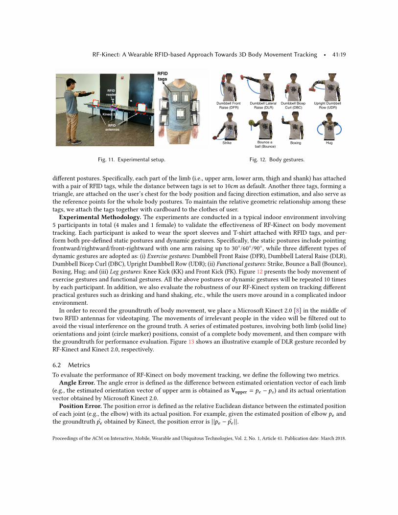
6.1 Experimental Setup & MethodologyExperimental Setup. The experimental setup of our RF-Kinect system, consisting of one dual-antenna RFIDreader and multiple wearable RFID tags, is presented in Figure 11. The ImpinJ Speedway modeled R420 RFIDreader integrated with two Laird S9028PCL directional antennas, which is compatible with EPCC1G2 standard, isplaced on a 80cm-high desk. The two antennas on the RFID reader are separated by 150cm from each other. TheRFID reader works in channel hopping mode over the frequency band 920 ∼ 926MHz, and scans the RFID tagswith both antennas. The user who wears RFID tags stands 200cm in front of the RFID reader while performing
Proceedings of the ACM on Interactive, Mobile, Wearable and Ubiquitous Technologies, Vol. 2, No. 1, Article 41. Publication date: March 2018.
RF-Kinect: A Wearable RFID-based Approach Towards 3D Body Movement Tracking • 41:19
RFID
antennas
RFID
reader
Kinect 2.0
RFID
tags
Fig. 11. Experimental setup.
!"#$$%&&'()*+,'
-./0%'1!(-2
!"#$$%&&'3.,%).&'
-./0%'1!3-2
!"#$$%&&'4/5%6
7")&'1!472
86)/9:,'!"#$$%&&'
-*;'18!-2
<,)/=% 4*"+5%'.'
$.&&'14*"+5%24*>/+9 ?"9
Fig. 12. Body gestures.
different postures. Specifically, each part of the limb (i.e., upper arm, lower arm, thigh and shank) has attachedwith a pair of RFID tags, while the distance between tags is set to 10cm as default. Another three tags, forming atriangle, are attached on the user’s chest for the body position and facing direction estimation, and also serve asthe reference points for the whole body postures. To maintain the relative geometric relationship among thesetags, we attach the tags together with cardboard to the clothes of user.Experimental Methodology. The experiments are conducted in a typical indoor environment involving
5 participants in total (4 males and 1 female) to validate the effectiveness of RF-Kinect on body movementtracking. Each participant is asked to wear the sport sleeves and T-shirt attached with RFID tags, and per-form both pre-defined static postures and dynamic gestures. Specifically, the static postures include pointingfrontward/rightward/front-rightward with one arm raising up to 30◦/60◦/90◦, while three different types ofdynamic gestures are adopted as: (i) Exercise gestures: Dumbbell Front Raise (DFR), Dumbbell Lateral Raise (DLR),Dumbbell Bicep Curl (DBC), Upright Dumbbell Row (UDR); (ii) Functional gestures: Strike, Bounce a Ball (Bounce),Boxing, Hug; and (iii) Leg gestures: Knee Kick (KK) and Front Kick (FK). Figure 12 presents the body movement ofexercise gestures and functional gestures. All the above postures or dynamic gestures will be repeated 10 timesby each participant. In addition, we also evaluate the robustness of our RF-Kinect system on tracking differentpractical gestures such as drinking and hand shaking, etc., while the users move around in a complicated indoorenvironment.In order to record the groundtruth of body movement, we place a Microsoft Kinect 2.0 [8] in the middle of
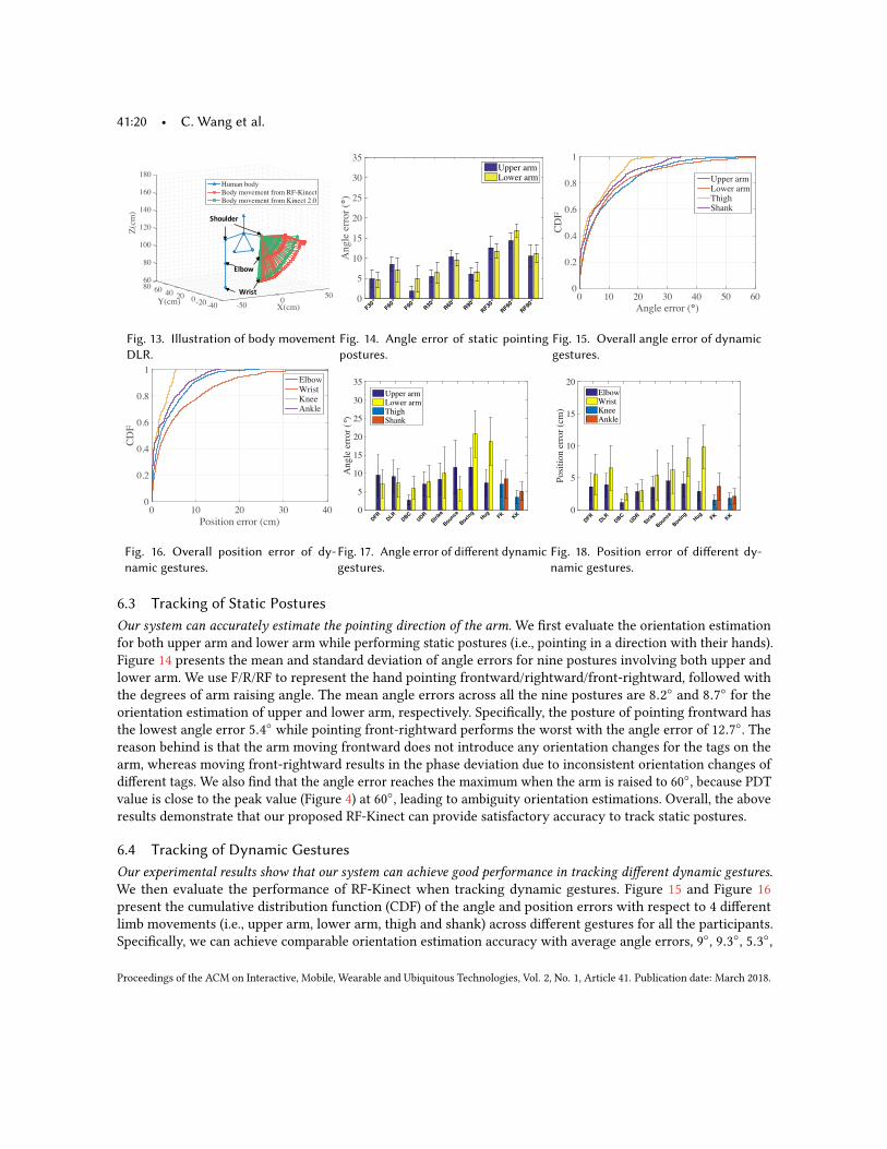
two RFID antennas for videotaping. The movements of irrelevant people in the video will be filtered out toavoid the visual interference on the ground truth. A series of estimated postures, involving both limb (solid line)orientations and joint (circle marker) positions, consist of a complete body movement, and then compare withthe groundtruth for performance evaluation. Figure 13 shows an illustrative example of DLR gesture recorded byRF-Kinect and Kinect 2.0, respectively.
6.2 MetricsTo evaluate the performance of RF-Kinect on body movement tracking, we define the following two metrics.
Angle Error. The angle error is defined as the difference between estimated orientation vector of each limb(e.g., the estimated orientation vector of upper arm is obtained as Vupper = pe − ps ) and its actual orientationvector obtained by Microsoft Kinect 2.0.
Position Error. The position error is defined as the relative Euclidean distance between the estimated positionof each joint (e.g., the elbow) with its actual position. For example, given the estimated position of elbow pe andthe groundtruth p̂e obtained by Kinect, the position error is | |pe − p̂e | |.
Proceedings of the ACM on Interactive, Mobile, Wearable and Ubiquitous Technologies, Vol. 2, No. 1, Article 41. Publication date: March 2018.
41:20 • C. Wang et al.
50
X(cm)0
-50-40-20020Y(cm)
4060
180
160
140
120
100
80
6080
Z(c
m)
Human body
Body movement from RF-Kinect
Body movement from Kinect 2.0
!"#$%&'(
)%*#+
,(-./
Fig. 13. Illustration of body movementDLR.
Angle
err
or
(°)
0
5
10
15
20
25
30
35
F30°
F60°
F90°
R30°
R60°
R90°
RF30°
RF60°
RF90°
Upper armLower arm
Fig. 14. Angle error of static pointingpostures.
Angle error (°)0 10 20 30 40 50 60
CD
F
0
0.2
0.4
0.6
0.8
1
Upper armLower armThighShank
Fig. 15. Overall angle error of dynamicgestures.
Position error (cm)
0 10 20 30 40
CD
F
0
0.2
0.4
0.6
0.8
1Elbow
Wrist
Knee
Ankle
Fig. 16. Overall position error of dy-namic gestures.
An
gle
err
or
(°)
0
5
10
15
20
25
30
35
DFR
DLR
DBC
UDR
Strik
e
Bounce
Boxi
ngHug
FK
KK
Upper armLower armThighShank
Fig. 17. Angle error of different dynamicgestures.
Po
siti
on
err
or
(cm
)
0
5
10
15
20
DFR
DLR
DBC
UDR
Strik
e
Bounce
Boxi
ngHug
FK
KK
ElbowWristKneeAnkle
Fig. 18. Position error of different dy-namic gestures.
6.3 Tracking of Static PosturesOur system can accurately estimate the pointing direction of the arm.We first evaluate the orientation estimationfor both upper arm and lower arm while performing static postures (i.e., pointing in a direction with their hands).Figure 14 presents the mean and standard deviation of angle errors for nine postures involving both upper andlower arm. We use F/R/RF to represent the hand pointing frontward/rightward/front-rightward, followed withthe degrees of arm raising angle. The mean angle errors across all the nine postures are 8.2◦ and 8.7◦ for theorientation estimation of upper and lower arm, respectively. Specifically, the posture of pointing frontward hasthe lowest angle error 5.4◦ while pointing front-rightward performs the worst with the angle error of 12.7◦. Thereason behind is that the arm moving frontward does not introduce any orientation changes for the tags on thearm, whereas moving front-rightward results in the phase deviation due to inconsistent orientation changes ofdifferent tags. We also find that the angle error reaches the maximum when the arm is raised to 60◦, because PDTvalue is close to the peak value (Figure 4) at 60◦, leading to ambiguity orientation estimations. Overall, the aboveresults demonstrate that our proposed RF-Kinect can provide satisfactory accuracy to track static postures.
6.4 Tracking of Dynamic GesturesOur experimental results show that our system can achieve good performance in tracking different dynamic gestures.We then evaluate the performance of RF-Kinect when tracking dynamic gestures. Figure 15 and Figure 16present the cumulative distribution function (CDF) of the angle and position errors with respect to 4 differentlimb movements (i.e., upper arm, lower arm, thigh and shank) across different gestures for all the participants.Specifically, we can achieve comparable orientation estimation accuracy with average angle errors, 9◦, 9.3◦, 5.3◦,
Proceedings of the ACM on Interactive, Mobile, Wearable and Ubiquitous Technologies, Vol. 2, No. 1, Article 41. Publication date: March 2018.
RF-Kinect: A Wearable RFID-based Approach Towards 3D Body Movement Tracking • 41:21S
earc
hin
g t
ime
(ms)
0
1
2
3
4
5
3D Limb3D Limb
& AoA
3D Limb,
AoA & RD
(a) Searching time of different modulesA
ng
le e
rro
r (°
)
0
5
10
15
20
3D Limb3D Limb
& AoA
3D Limb,
AoA & RD
(b) Angle error of different modules
Po
siti
on
err
or
(cm
)
0
2
4
6
8
10
12
3D Limb3D Limb
& AoA
3D Limb,
AoA & RD
(c) Position error of different modules
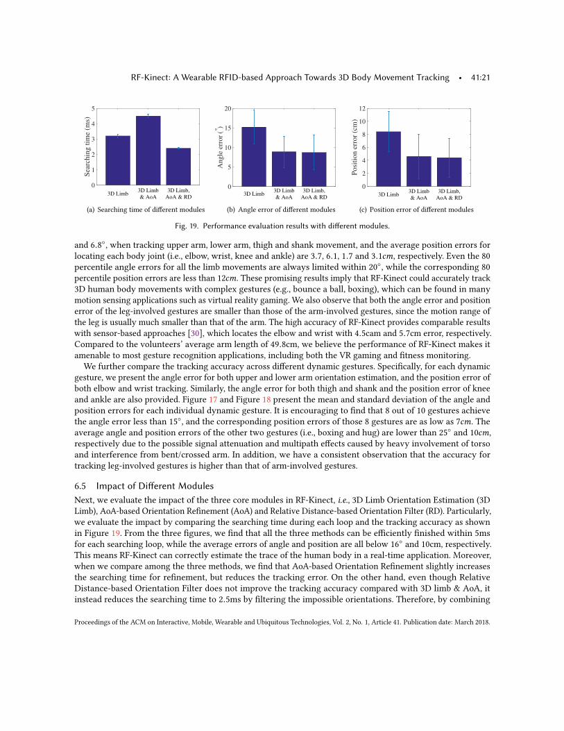
Fig. 19. Performance evaluation results with different modules.
and 6.8◦, when tracking upper arm, lower arm, thigh and shank movement, and the average position errors forlocating each body joint (i.e., elbow, wrist, knee and ankle) are 3.7, 6.1, 1.7 and 3.1cm, respectively. Even the 80percentile angle errors for all the limb movements are always limited within 20◦, while the corresponding 80percentile position errors are less than 12cm. These promising results imply that RF-Kinect could accurately track3D human body movements with complex gestures (e.g., bounce a ball, boxing), which can be found in manymotion sensing applications such as virtual reality gaming. We also observe that both the angle error and positionerror of the leg-involved gestures are smaller than those of the arm-involved gestures, since the motion range ofthe leg is usually much smaller than that of the arm. The high accuracy of RF-Kinect provides comparable resultswith sensor-based approaches [30], which locates the elbow and wrist with 4.5cam and 5.7cm error, respectively.Compared to the volunteers’ average arm length of 49.8cm, we believe the performance of RF-Kinect makes itamenable to most gesture recognition applications, including both the VR gaming and fitness monitoring.We further compare the tracking accuracy across different dynamic gestures. Specifically, for each dynamic
gesture, we present the angle error for both upper and lower arm orientation estimation, and the position error ofboth elbow and wrist tracking. Similarly, the angle error for both thigh and shank and the position error of kneeand ankle are also provided. Figure 17 and Figure 18 present the mean and standard deviation of the angle andposition errors for each individual dynamic gesture. It is encouraging to find that 8 out of 10 gestures achievethe angle error less than 15◦, and the corresponding position errors of those 8 gestures are as low as 7cm. Theaverage angle and position errors of the other two gestures (i.e., boxing and hug) are lower than 25◦ and 10cm,respectively due to the possible signal attenuation and multipath effects caused by heavy involvement of torsoand interference from bent/crossed arm. In addition, we have a consistent observation that the accuracy fortracking leg-involved gestures is higher than that of arm-involved gestures.
6.5 Impact of Different ModulesNext, we evaluate the impact of the three core modules in RF-Kinect, i.e., 3D Limb Orientation Estimation (3DLimb), AoA-based Orientation Refinement (AoA) and Relative Distance-based Orientation Filter (RD). Particularly,we evaluate the impact by comparing the searching time during each loop and the tracking accuracy as shownin Figure 19. From the three figures, we find that all the three methods can be efficiently finished within 5msfor each searching loop, while the average errors of angle and position are all below 16◦ and 10cm, respectively.This means RF-Kinect can correctly estimate the trace of the human body in a real-time application. Moreover,when we compare among the three methods, we find that AoA-based Orientation Refinement slightly increasesthe searching time for refinement, but reduces the tracking error. On the other hand, even though RelativeDistance-based Orientation Filter does not improve the tracking accuracy compared with 3D limb & AoA, itinstead reduces the searching time to 2.5ms by filtering the impossible orientations. Therefore, by combining
Proceedings of the ACM on Interactive, Mobile, Wearable and Ubiquitous Technologies, Vol. 2, No. 1, Article 41. Publication date: March 2018.
41:22 • C. Wang et al.
Antenna distance (m)0.5 1 1.5
Angle
Err
or
(°)
0
10
20
30
(a) Angle error of different an-tenna distances
Antenna distance (m)
0.5 1 1.5
Po
siti
on
Err
or
(cm
)
0
5
10
15
20
25
(b) Position error of different an-tenna distances
Tag distance (cm)4 6 8 10 12
An
gle
Err
or
(°)
0
5
10
15
20
25
30
35
(c) Angle error of different tag dis-tances
tag distance (cm)4 6 8 10 12
Po
siti
on
Err
or
(cm
)
0
5
10
15
20
25
30
(d) Position error of different tagdistances
Grid id0 1 2 4 5 9
Angle
err
or
(°)
0
10
20
30
(e) Angle error when standing atdifferent grids
Grid id
0 1 2 4 5 9
Po
siti
on
err
or
(cm
)
0
5
10
15
20
(f) Position error when standing atdifferent grids
Body direction (°) -20 0 20
Angle
err
or
(°)
0
10
20
30
(g) Angle error when standing atdifferent orientations
Body direction (°) -20 0 20
Posi
tion e
rror
(cm
)
0
5
10
15
20
(h) Position error when standingat different orientations
Fig. 20. Performance evaluation results with different system configurations and user locations/orientations.
the three methods, RF-Kinect can efficiently and accurately track the human movements, which can be used indifferent kinds of gesture recognition applications.
6.6 Impact of Different Distances between AntennasWe next evaluate the impact of the distance between antennas on the accuracy of body movement tracking.Specifically, we vary the distance between two antennas from 0.5m to 1.5m with the incremental step 0.2m.Given a specific distance between two antennas, the user is asked to perform 8 different dynamic gestures, eachrepeating 10 times, at around 200cm in front of the antennas. As shown in Figure 20(a) and Figure 20(b), boththe angle error and position error decreases as the distance between two antennas increases. The rationalebehind the above results is that larger distance can achieve higher resolution on AoA estimation, and therebyboost the tracking accuracy. In particular, when the distance between two antennas is larger than 1m, the angleerror and position error are less than 13.3◦ and 7.4cm, respectively, which are accurate enough to perform bodymovement tracking. It is worth noting that the increasing distance between antennas will also create more spatialambiguity due to the AoA model [35]. However, since RF-Kinect tracks the relative rotation of each limb from thephase changes instead of the absolution positions, the spatial ambiguity can be eliminated from the continuousmovement of each tag. Moreover, 3D Orientation Estimation and Relative Distance calculation is insensitive tothe actual position as shown in Figure 7(c) and Figure 9(c), so we can still accurately track the gestures even AoAmodel leads to some spatial error at the first timestamp.
6.7 Impact of Different Distances between TagsWe next evaluate the impact of the distance between tags on the accuracy of body movement tracking. Specifically,we vary the distance between two tags on the limb from 5cm to 12cm with the incremental step 1cm. Given aspecific distance between tags, the user is asked to perform 8 different dynamic gestures, each repeating 10 times,at around 200cm in front of the antennas. As shown in Figure 20(c) and Figure 20(d), we find both the angle
Proceedings of the ACM on Interactive, Mobile, Wearable and Ubiquitous Technologies, Vol. 2, No. 1, Article 41. Publication date: March 2018.
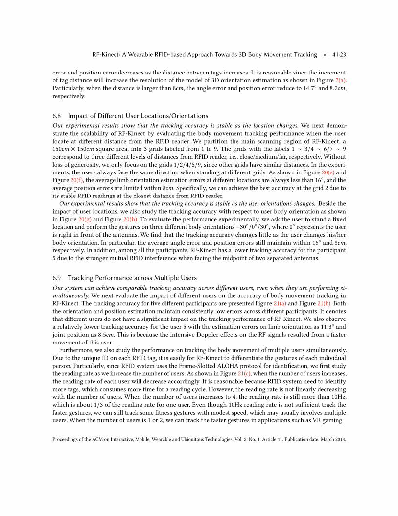
RF-Kinect: A Wearable RFID-based Approach Towards 3D Body Movement Tracking • 41:23
error and position error decreases as the distance between tags increases. It is reasonable since the incrementof tag distance will increase the resolution of the model of 3D orientation estimation as shown in Figure 7(a).Particularly, when the distance is larger than 8cm, the angle error and position error reduce to 14.7◦ and 8.2cm,respectively.
6.8 Impact of Different User Locations/OrientationsOur experimental results show that the tracking accuracy is stable as the location changes. We next demon-strate the scalability of RF-Kinect by evaluating the body movement tracking performance when the userlocate at different distance from the RFID reader. We partition the main scanning region of RF-Kinect, a150cm × 150cm square area, into 3 grids labeled from 1 to 9. The grids with the labels 1 ∼ 3/4 ∼ 6/7 ∼ 9correspond to three different levels of distances from RFID reader, i.e., close/medium/far, respectively. Withoutloss of generosity, we only focus on the grids 1/2/4/5/9, since other grids have similar distances. In the experi-ments, the users always face the same direction when standing at different grids. As shown in Figure 20(e) andFigure 20(f), the average limb orientation estimation errors at different locations are always less than 16◦, and theaverage position errors are limited within 8cm. Specifically, we can achieve the best accuracy at the grid 2 due toits stable RFID readings at the closest distance from RFID reader.Our experimental results show that the tracking accuracy is stable as the user orientations changes. Beside the
impact of user locations, we also study the tracking accuracy with respect to user body orientation as shownin Figure 20(g) and Figure 20(h). To evaluate the performance experimentally, we ask the user to stand a fixedlocation and perform the gestures on three different body orientations −30◦/0◦/30◦, where 0◦ represents the useris right in front of the antennas. We find that the tracking accuracy changes little as the user changes his/herbody orientation. In particular, the average angle error and position errors still maintain within 16◦ and 8cm,respectively. In addition, among all the participants, RF-Kinect has a lower tracking accuracy for the participant5 due to the stronger mutual RFID interference when facing the midpoint of two separated antennas.
6.9 Tracking Performance across Multiple UsersOur system can achieve comparable tracking accuracy across different users, even when they are performing si-multaneously. We next evaluate the impact of different users on the accuracy of body movement tracking inRF-Kinect. The tracking accuracy for five different participants are presented Figure 21(a) and Figure 21(b). Boththe orientation and position estimation maintain consistently low errors across different participants. It denotesthat different users do not have a significant impact on the tracking performance of RF-Kinect. We also observea relatively lower tracking accuracy for the user 5 with the estimation errors on limb orientation as 11.3◦ andjoint position as 8.5cm. This is because the intensive Doppler effects on the RF signals resulted from a fastermovement of this user.
Furthermore, we also study the performance on tracking the body movement of multiple users simultaneously.Due to the unique ID on each RFID tag, it is easily for RF-Kinect to differentiate the gestures of each individualperson. Particularly, since RFID system uses the Frame-Slotted ALOHA protocol for identification, we first studythe reading rate as we increase the number of users. As shown in Figure 21(c), when the number of users increases,the reading rate of each user will decrease accordingly. It is reasonable because RFID system need to identifymore tags, which consumes more time for a reading cycle. However, the reading rate is not linearly decreasingwith the number of users. When the number of users increases to 4, the reading rate is still more than 10Hz,which is about 1/3 of the reading rate for one user. Even though 10Hz reading rate is not sufficient track thefaster gestures, we can still track some fitness gestures with modest speed, which may usually involves multipleusers. When the number of users is 1 or 2, we can track the faster gestures in applications such as VR gaming.
Proceedings of the ACM on Interactive, Mobile, Wearable and Ubiquitous Technologies, Vol. 2, No. 1, Article 41. Publication date: March 2018.
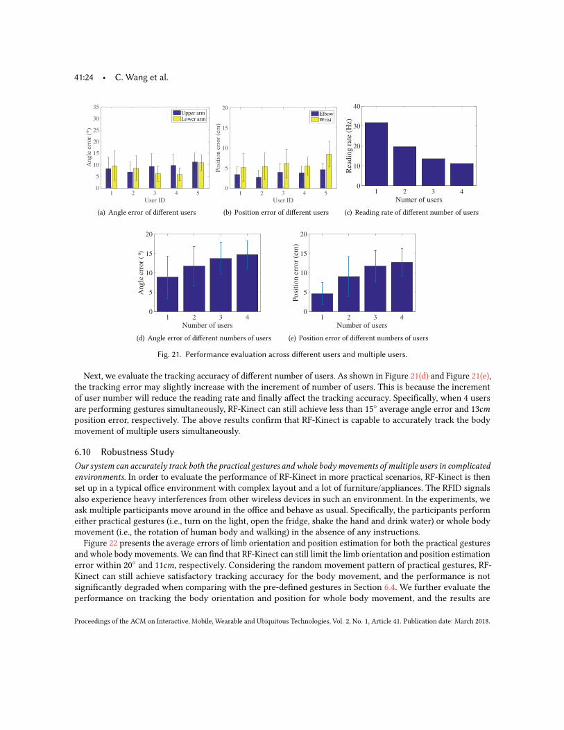
41:24 • C. Wang et al.
User ID
1 2 3 4 5
Angle
err
or
(°)
0
5
10
15
20
25
30
35Upper armLower arm
(a) Angle error of different users
User ID
1 2 3 4 5
Posi
tion e
rror
(cm
)
0
5
10
15
20ElbowWrist
(b) Position error of different users
Numer of users1 2 3 4
Rea
din
g r
ate
(Hz)
0
10
20
30
40
(c) Reading rate of different number of users
Number of users1 2 3 4
An
gle
err
or
(°)
0
5
10
15
20
(d) Angle error of different numbers of users
Number of users1 2 3 4
Posi
tion e
rror
(cm
)
0
5
10
15
20
(e) Position error of different numbers of users
Fig. 21. Performance evaluation across different users and multiple users.
Next, we evaluate the tracking accuracy of different number of users. As shown in Figure 21(d) and Figure 21(e),the tracking error may slightly increase with the increment of number of users. This is because the incrementof user number will reduce the reading rate and finally affect the tracking accuracy. Specifically, when 4 usersare performing gestures simultaneously, RF-Kinect can still achieve less than 15◦ average angle error and 13cmposition error, respectively. The above results confirm that RF-Kinect is capable to accurately track the bodymovement of multiple users simultaneously.
6.10 Robustness StudyOur system can accurately track both the practical gestures and whole bodymovements of multiple users in complicatedenvironments. In order to evaluate the performance of RF-Kinect in more practical scenarios, RF-Kinect is thenset up in a typical office environment with complex layout and a lot of furniture/appliances. The RFID signalsalso experience heavy interferences from other wireless devices in such an environment. In the experiments, weask multiple participants move around in the office and behave as usual. Specifically, the participants performeither practical gestures (i.e., turn on the light, open the fridge, shake the hand and drink water) or whole bodymovement (i.e., the rotation of human body and walking) in the absence of any instructions.
Figure 22 presents the average errors of limb orientation and position estimation for both the practical gesturesand whole body movements. We can find that RF-Kinect can still limit the limb orientation and position estimationerror within 20◦ and 11cm, respectively. Considering the random movement pattern of practical gestures, RF-Kinect can still achieve satisfactory tracking accuracy for the body movement, and the performance is notsignificantly degraded when comparing with the pre-defined gestures in Section 6.4. We further evaluate theperformance on tracking the body orientation and position for whole body movement, and the results are
Proceedings of the ACM on Interactive, Mobile, Wearable and Ubiquitous Technologies, Vol. 2, No. 1, Article 41. Publication date: March 2018.
RF-Kinect: A Wearable RFID-based Approach Towards 3D Body Movement Tracking • 41:25A
ngle
err
or
(°)
0
5
10
15
20
25
30
35
Turn on
light
Open the
fridge
Hand
shakeDrink
(a) Angle error of practical ges-tures
Po
siti
on
err
or
(cm
)
0
5
10
15
20
Turn on
light
Open the
fridge
Hand
shakeDrink
(b) Position error of practical ges-tures
Angle error (°)0 20 40 60
CD
F
0
0.2
0.4
0.6
0.8
1WalkingBody rotation
(c) Angle error of body orientationestimation
Position error (cm)0 20 40 60
CD
F
0
0.2
0.4
0.6
0.8
1
WalkingBody rotation
(d) Position error of body positionestimation
Fig. 22. Performance evaluation results of practical gestures and whole body gestures.
presented in Figure 22(c) and Figure 22(d). As depicted in the experimental setup, we have the three tags attachedon user’s chest for body orientation and position tracking. Specifically, the existing method [21] is deployed tolocate the human body. It is obvious that RF-Kinect achieves higher tracking accuracy for whole body movementsthan practical gestures. This is because whole body movements have less involvement of limb movement thatmay produce strong interference on the RF signal propagation.
6.11 Impact of Blocks in NLOS EnvironmentRF-Kinect can still accurately track the gestures in NLOS environment. In real application scenarios, there may existdifferent kinds of objects that block the line-of-sight path between the user and RFID antennas. Therefore, itis essential to study the performance of RF-Kinect in these NLOS environment. Particularly, we first study thechange of phase measurement when different kinds of objects block the LOS path (i.e., Bottles, Glass, Box andBooks). As shown in Figure 23(a), we find while the glass and books reduce the phase about 1 radian, both thebottle and box almost do not change the phase value. It means RF-Kinect can work similar to the free space evenif the bottle and box block the LOS path, but vision-based approaches cannot work in such situations.Moreover, we evaluate the tracking performance of dynamic gestures when the glass or books block the
LOS path. As shown in Figure 23(b) and Figure 23(c), we find the accuracy of both situations is slightly smallerthan the free space, due to the multi-path effect in NLOS environment. However, such accuracy (i.e., about 20◦angle error and 10cm position error) is still sufficient for gesture recognition compared with some sensor-basedapproaches [30]. The reason of such accurate results in NLOS environment may be that the tags attached on oneperson may suffer from similar multi-path effect. Therefore, when we calculate the phase differences betweentags to estimate the orientations, the multi-path effect is canceled by each other. Finally, we can still accuratelytrack the gestures in the NLOS environment.
7 DISCUSSIONNumber ofWearable Tags on Each Individual Limb. The limited limb length only allows two wearable RFIDtags to be attached, but we can still achieve good orientation estimation accuracy. To evaluate the performancewith more wearable tags, we also emulate the limb rotation with one stick that is longer than any limb. We findthat as the tag number increases from 2 to 4, the orientation estimation accuracy only has 3◦ improvement. Itimplies that two tags on each limb have already ensured sufficiently high accuracy on tracking body movement.Nevertheless, as the advancement of RFID techniques, it is possible to have a dense deployment of wearable RFIDtags with reduced size in the future.Tracking Accuracy and Missing Tags. Currently, some tracking error is still as large as 30◦, which is notaccurate enough compared with real Kinect. By in deep analyzing the data, we find the tracking trace is exactlythe same as shown in Figure 13, but the speed of each gesture can not be correctly estimated, leading to large
Proceedings of the ACM on Interactive, Mobile, Wearable and Ubiquitous Technologies, Vol. 2, No. 1, Article 41. Publication date: March 2018.
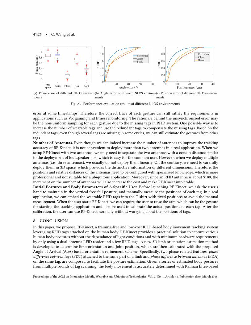
41:26 • C. Wang et al.P
has
e (r
adia
n)
3
3.2
3.4
3.6
3.8
4
Free
spaceBottle Glass Box Book
(a) Phase error of different NLOS environ-ments
Angle error (°)0 20 40 60 80
CD
F
0
0.2
0.4
0.6
0.8
1
Free spaceGlassBook
(b) Angle error of different NLOS environ-ments
Position error (cm)0 10 20 30 40
CD
F
0
0.2
0.4
0.6
0.8
1
Free spaceGlassBook
(c) Position error of different NLOS environ-ments
Fig. 23. Performance evaluation results of different NLOS environments.
error at some timestamps. Therefore, the correct trace of each gesture can still satisfy the requirements inapplications such as VR gaming and fitness monitoring. The rationale behind the unsynchronized error maybe the non-uniform sampling for each gesture due to the missing tags in RFID system. One possible way is toincrease the number of wearable tags and use the redundant tags to compensate the missing tags. Based on theredundant tags, even though several tags are missing in some cycles, we can still estimate the gestures from othertags.Number of Antennas. Even though we can indeed increase the number of antennas to improve the trackingaccuracy of RF-Kinect, it is not convenient to deploy more than two antennas in a real application. When wesetup RF-Kinect with two antennas, we only need to separate the two antennas with a certain distance similarto the deployment of loudspeaker box, which is easy for the common user. However, when we deploy multipleantennas (i.e., three antennas), we usually do not deploy them linearly. On the contrary, we need to carefullydeploy them in 3D space, which provides the distinctive information of different dimensions. Therefore, thepositions and relative distances of the antennas need to be configured with specialized knowledge, which is moreprofessional and not suitable for a ubiquitous application. Moreover, since an RFID antenna is about $100, theincrement on the number of antennas will also increase the cost and make RF-Kinect intolerable.Initial Postures and Body Parameters of A Specific User. Before launching RF-Kinect, we ask the user’shand to maintain in the vertical free-fall posture, and manually measure the positions of each tag. In a realapplication, we can embed the wearable RFID tags into the T-shirt with fixed positions to avoid the manualmeasurement. When the user starts RF-Kinect, we can require the user to raise the arm, which can be the gesturefor starting the tracking application and also be used to calibrate the actual positions of each tag. After thecalibration, the user can use RF-Kinect normally without worrying about the positions of tags.
8 CONCLUSIONIn this paper, we propose RF-Kinect, a training-free and low-cost RFID-based body movement tracking systemleveraging RFID tags attached on the human body. RF-Kinect provides a practical solution to capture varioushuman body postures without the dependance of light conditions and with minimum hardware requirementsby only using a dual-antenna RFID reader and a few RFID tags. A new 3D limb orientation estimation methodis developed to determine limb orientation and joint position, which are then calibrated with the proposedAngle of Arrival (AoA) based orientation refinement scheme. Specifically, two phase related features, phasedifference between tags (PDT) attached to the same part of a limb and phase difference between antennas (PDA)on the same tag, are composed to facilitate the posture estimation. Given a series of estimated body posturesfrom multiple rounds of tag scanning, the body movement is accurately determined with Kalman filter-based
Proceedings of the ACM on Interactive, Mobile, Wearable and Ubiquitous Technologies, Vol. 2, No. 1, Article 41. Publication date: March 2018.
RF-Kinect: A Wearable RFID-based Approach Towards 3D Body Movement Tracking • 41:27
smoothing. Extensive experiments involving 5 volunteers are conducted in a typical indoor environment. Theexperimental results confirm the effectiveness on utilizing attached RFID tags for body movement tracking. Inparticular, RF-Kinect could achieve as lows as 8.7◦ average angle error for limb orientation estimation and 4.4cmposition error for joint position estimation in comparison with Microsoft Kinect 2.0.
ACKNOWLEDGMENTSThis work is partially supported by National Natural Science Foundation of China under Grant Nos. 61472185,61321491, 61502224; JiangSu Natural Science Foundation, No. BK20151390. This work is partially supported byCollaborative Innovation Center of Novel Software Technology and Industrialization. This work is partiallysupported by the program A for Outstanding PhD candidate of Nanjing University. This work is partiallysupported by the US National Science Foundation Grants CNS-1514436, CNS-1820624, CNS-1717356 and ArmyOffice Research Grant W911NF-17-1-0467.
REFERENCES[1] 2017. Average human arm length. https://www.reference.com/science/long-average-human-arm-62c7536c5e56f385.. (2017).[2] 2017. Cone - Wikipedia. https://en.wikipedia.org/wiki/Cone. (2017).[3] 2017. Fitbit. http://www.fitbit.com/. (2017).[4] 2017. Gesture Recognition Market-Global Industry Analysis Size Share Growth Trends and Forecast 2016-2024. http://www.
transparencymarketresearch.com/gesture-recognition-market.html.. (2017).[5] 2017. Leap Motion. https://www.leapmotion.com. (2017).[6] 2017. Motion capture systems | Vicon. https://www.vicon.com. (2017).[7] 2017. Rigid body - Wikipedia. https://en.wikipedia.org/wiki/RigidBody.. (2017).[8] 2017. X-box Kinect. http://www.xbox.com. (2017).[9] Fadel Adib, Chen-Yu Hsu, Hongzi Mao, Dina Katabi, and Frédo Durand. 2015. Capturing the human figure through a wall. ACM
Transactions on Graphics (TOG) 34, 6 (2015), 219.[10] Fadel Adib, Zachary Kabelac, and Dina Katabi. 2015. Multi-person motion tracking via RF body reflections. In Proc. of USENIX NSDI.[11] Sena Agezo, Yuxiang Zhang, Ziyu Ye, Somesh Chopra, Shrenik Vora, and Timothy Kurzweg. 2016. Battery-free RFID heart rate
monitoring system. In Proc. of IEEE Wireless Health (WH). IEEE.[12] Jacques Denavit. 1955. A kinematic notation for lower-pair mechanisms based on matrices. Trans. of the ASME. Journal of Applied
Mechanics (1955).[13] Han Ding, Longfei Shangguan, Zheng Yang, Jinsong Han, Zimu Zhou, Panlong Yang, Wei Xi, and Jizhong Zhao. 2015. Femo: A platform
for free-weight exercise monitoring with rfids. In Proc. of ACM SenSys.[14] M. Hazewinkel. 1987. Encyclopaedia of Mathematics. Springer. https://books.google.com/books?id=WzbzxytdAuUC[15] Wenjun Hu, Hao Gu, and Qifan Pu. 2013. LightSync: unsynchronized visual communication over screen-camera links. In Proceedings of
the 19th annual international conference on Mobile computing & networking. ACM, 15–26.[16] Mostafa Izz, Zhongyuan Li, Hongbo Liu, Yingying Chen, and Feng Li. [n. d.]. Uber-in-Light: Unobtrusive Visible Light Communication
Leveraging Complementary Color Channel.[17] Bryce Kellogg, Vamsi Talla, and Shyamnath Gollakota. 2014. Bringing gesture recognition to all devices. In Proc. of USENIX NSDI.[18] Ye-Sheng Kuo, Pat Pannuto, Ko-Jen Hsiao, and Prabal Dutta. 2014. Luxapose: Indoor positioning with mobile phones and visible light. In
Proc. of ACM Mobicom.[19] Oscar D Lara and Miguel A Labrador. 2013. A survey on human activity recognition using wearable sensors. IEEE Communications
Surveys & Tutorials (2013).[20] Tianxing Li, Chuankai An, Zhao Tian, Andrew T Campbell, and Xia Zhou. 2015. Human sensing using visible light communication. In
Proc. of ACM MobiCom.[21] Qiongzheng Lin, Lei Yang, Yuxin Sun, Tianci Liu, Xiang-Yang Li, and Yunhao Liu. 2015. Beyond one-dollar mouse: A battery-free device
for 3d human-computer interaction via rfid tags. In Proc. of IEEE INFOCOM.[22] Chang Liu, Lei Xie, Chuyu Wang, J Wu, and Sanglu Lu. 2016. Track Your Foot Step: Anchor-free Indoor Localization based on Sensing
Users’ Foot Steps. In Proc. of IEEE MASS.[23] Abhinav Parate, Meng-Chieh Chiu, Chaniel Chadowitz, Deepak Ganesan, and Evangelos Kalogerakis. 2014. RisQ: recognizing smoking
gestures with inertial sensors on a wristband. In Proc. of ACM MobiSys.[24] Joel C Perry and Jacob Rosen. 2006. Design of a 7 degree-of-freedom upper-limb powered exoskeleton. In Proc. of IEEE BioRob.
Proceedings of the ACM on Interactive, Mobile, Wearable and Ubiquitous Technologies, Vol. 2, No. 1, Article 41. Publication date: March 2018.
41:28 • C. Wang et al.
[25] Qifan Pu, Sidhant Gupta, Shyamnath Gollakota, and Shwetak Patel. 2013. Whole-home gesture recognition using wireless signals. InProc. of ACM MobiCom.
[26] Longfei Shangguan and Kyle Jamieson. 2016. The Design and Implementation of a Mobile RFID Tag Sorting Robot. In Proc. of ACMMobiSys.
[27] Longfei Shangguan and Kyle Jamieson. 2016. Leveraging Electromagnetic Polarization in a Two-Antenna Whiteboard in the Air. InProceedings of the 12th International on Conference on emerging Networking EXperiments and Technologies. ACM, 443–456.
[28] Longfei Shangguan, Zheng Yang, Alex X Liu, Zimu Zhou, and Yunhao Liu. 2015. Relative localization of rfid tags using spatial-temporalphase profiling. In Proc. of USENIX NSDI.
[29] Longfei Shangguan, Zimu Zhou, and Kyle Jamieson. [n. d.]. Enabling Gesture-based Interactions with Objects. In Proc. of ACM Mobisys.[30] Sheng Shen, He Wang, and Romit Roy Choudhury. 2016. I am a Smartwatch and I can Track my Userąŕs Arm. In Proc. of ACM MobiSys.[31] Li Sun, Souvik Sen, Dimitrios Koutsonikolas, and Kyu-Han Kim. 2015. Widraw: Enabling hands-free drawing in the air on commodity
wifi devices. In Proceedings of the 21st Annual International Conference on Mobile Computing and Networking. ACM, 77–89.[32] Daniel Vlasic, Rolf Adelsberger, Giovanni Vannucci, John Barnwell, Markus Gross, Wojciech Matusik, and Jovan Popović. 2007. Practical
motion capture in everyday surroundings. In ACM transactions on graphics (TOG), Vol. 26. Acm, 35.[33] He Wang, Ted Tsung-Te Lai, and Romit Roy Choudhury. 2015. MoLe: Motion Leaks Through Smartwatch Sensors. In Proc. of ACM
MobiCom.[34] Jue Wang and Dina Katabi. 2013. Dude, where’s my card?: RFID positioning that works with multipath and NOLS. In Proc. of ACM
SIGCOMM.[35] Jue Wang, Deepak Vasisht, and Dina Katabi. 2015. RF-IDraw: virtual touch screen in the air using RF signals. In Proc. of ACM SIGCOMM.[36] Ju Wang, Jie Xiong, Hongbo Jiang, Xiaojiang Chen, and Dingyi Fang. 2016. D-watch: Embracing" bad" multipaths for device-free
localization with COTS RFID devices. (2016), 253–266.[37] Wei Wang, Alex X Liu, Muhammad Shahzad, Kang Ling, and Sanglu Lu. 2015. Understanding and modeling of wifi signal based human
activity recognition. In Proceedings of the 21st Annual International Conference on Mobile Computing and Networking. ACM, 65–76.[38] Wei Wang, Alex X Liu, and Ke Sun. 2016. Device-free gesture tracking using acoustic signals. In Proceedings of the 22nd Annual
International Conference on Mobile Computing and Networking. ACM, 82–94.[39] Teng Wei and Xinyu Zhang. 2016. Gyro in the air: tracking 3D orientation of batteryless internet-of-things. In Proc. of ACM Mobicom.
55–68.[40] Chao Xu, Parth H Pathak, and Prasant Mohapatra. 2015. Finger-writing with Smartwatch: A Case for Finger and Hand Gesture
Recognition using Smartwatch. In Proceedings of the 16th International Workshop on Mobile Computing Systems and Applications (ACMHotMobile). ACM, 9–14.
[41] Lei Yang, Yekui Chen, Xiang-Yang Li, Chaowei Xiao, Mo Li, and Yunhao Liu. 2014. Tagoram: Real-time tracking of mobile RFID tags tohigh precision using COTS devices. In Proc. of ACM MobiCom.
[42] Lei Yang, Yao Li, Qiongzheng Lin, Huanyu Jia, Xiang-Yang Li, and Yunhao Liu. 2017. Tagbeat: Sensing Mechanical Vibration PeriodWith COTS RFID Systems. IEEE/ACM Transactions on Networking 25 (2017), 3823–3835.
[43] Lei Yang, Qiongzheng Lin, Xiangyang Li, Tianci Liu, and Yunhao Liu. 2015. See through walls with cots rfid system!. In Proceedings ofthe 21st Annual International Conference on Mobile Computing and Networking. ACM, 487–499.
[44] Zheng Yang, Chenshu Wu, Zimu Zhou, Xinglin Zhang, Xu Wang, and Yunhao Liu. 2015. Mobility increases localizability: A survey onwireless indoor localization using inertial sensors. ACM Computing Surveys (CSUR) 47, 3 (2015), 54.
[45] Xiaojun Zhu, Qun Li, and Guihai Chen. 2013. APT: Accurate outdoor pedestrian tracking with smartphones. In Proc. of IEEE INFOCOM.
Received May 2017; revised November 2017; accepted January 2018
Proceedings of the ACM on Interactive, Mobile, Wearable and Ubiquitous Technologies, Vol. 2, No. 1, Article 41. Publication date: March 2018.