Embed Size (px)
DESCRIPTION
RF Testbed for TCT D Fallon - Electronics Research Inc L Yan, G Hanson, S Patch - UWM. uncontrolled E-field & loss. ~10ns. Feng et al ‘01. Wisc ‘07. Goal - controlled illumination for large FOV imaging. optimized match. ?match?. - PowerPoint PPT Presentation
Citation preview
TCT testbed
RF Testbed for TCT
D Fallon - Electronics Research IncL Yan, G Hanson, S Patch - UWM
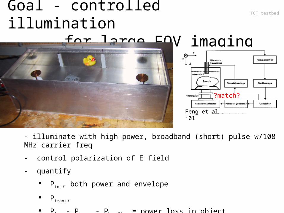
TCT testbedGoal - controlled illumination for large FOV imaging
- illuminate with high-power, broadband (short) pulse w/108 MHz carrier freq
- control polarization of E field
- quantify
Pinc, both power and envelope
Ptrans,
Pinc - Ptrans - Pbaseline = power loss in object
Feng et al ‘01 Wisc ‘07
optimized m
atch ~10ns
uncontrolled E-field & loss
?match?
TCT testbed
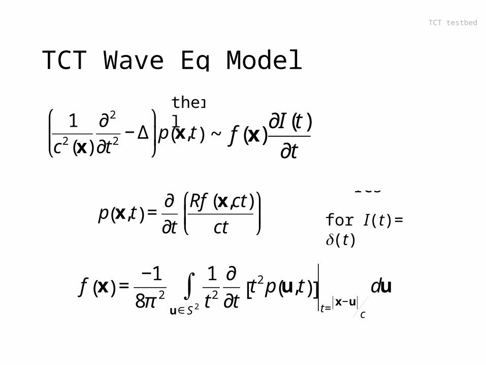
TCT Wave Eq Model
+ homog ICs
€
1
c2 (x)
∂ 2
∂t 2− Δ
⎛
⎝ ⎜
⎞
⎠ ⎟p x, t( ) =
βB( )(x)
C(x)σ x,ω( )
∂ E(x, t)2
∂t
€
p x, t( ) =∂
∂t
Rf (x,ct)
ct
⎛
⎝ ⎜
⎞
⎠ ⎟
€
f x( ) =−1
8π 2
1
t 2
∂
∂tt 2 p u, t( )[ ]
t=x−u
cu∈S 2
∫ du
for I(t)= (t)
thermal mechanical
electrical
€
=2βBρ( )(x)
C(x)
σ x,ω( ) ∂∂t E(x, t)
2
( )
2ρ(x)
€
~ f (x)∂I (t)
∂t
TCT testbed
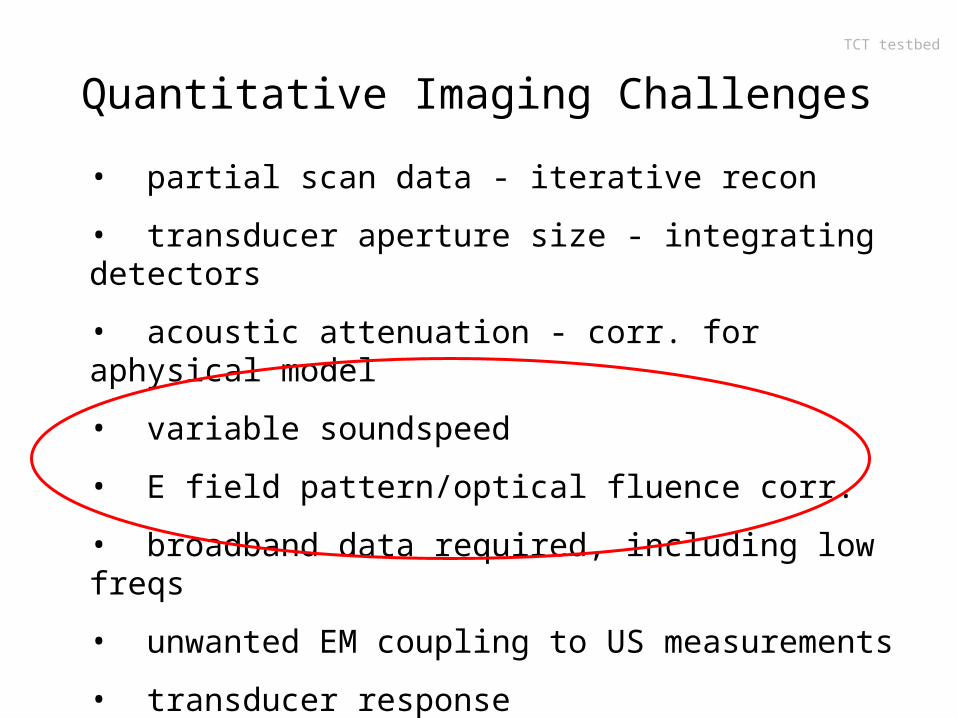
Quantitative Imaging Challenges
• partial scan data - iterative recon
• transducer aperture size - integrating detectors
• acoustic attenuation - corr. for aphysical model
• variable soundspeed
• E field pattern/optical fluence corr.
• broadband data required, including low freqs
• unwanted EM coupling to US measurements
• transducer response - freq dependent & has limited sensitivity - anisotropic
TCT testbed
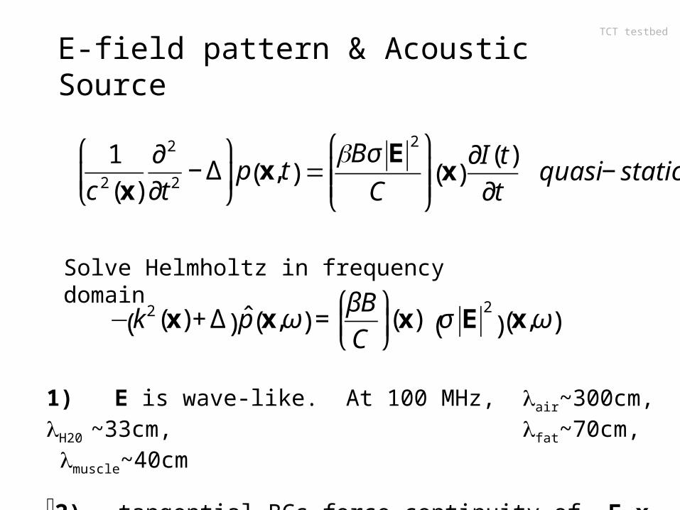
E-field pattern & Acoustic Source
€
1
c 2(x)
∂ 2
∂t 2− Δ
⎛
⎝ ⎜
⎞
⎠ ⎟p x, t( ) =
βB( )(x)
C(x)σ x,ω( )
∂E(x, t)2
∂t
€
=βBσ E
2
C
⎛
⎝ ⎜ ⎜
⎞
⎠ ⎟ ⎟ x( )
∂I(t)
∂t quasi − static
SOP to solve in frequency domain near carrier frequency.
€
−k2(x)+ Δ( ) ˆ p x,ω( ) =βB
C
⎛
⎝ ⎜
⎞
⎠ ⎟(x) σ E
2
( ) x,ω( )
1) E is wave-like. At 100 MHz, air~300cm, H20 ~33cm, fat~70cm, muscle~40cm
2) tangential BCs force continuity of E x n
Solve Helmholtz in frequency domain
TCT testbed
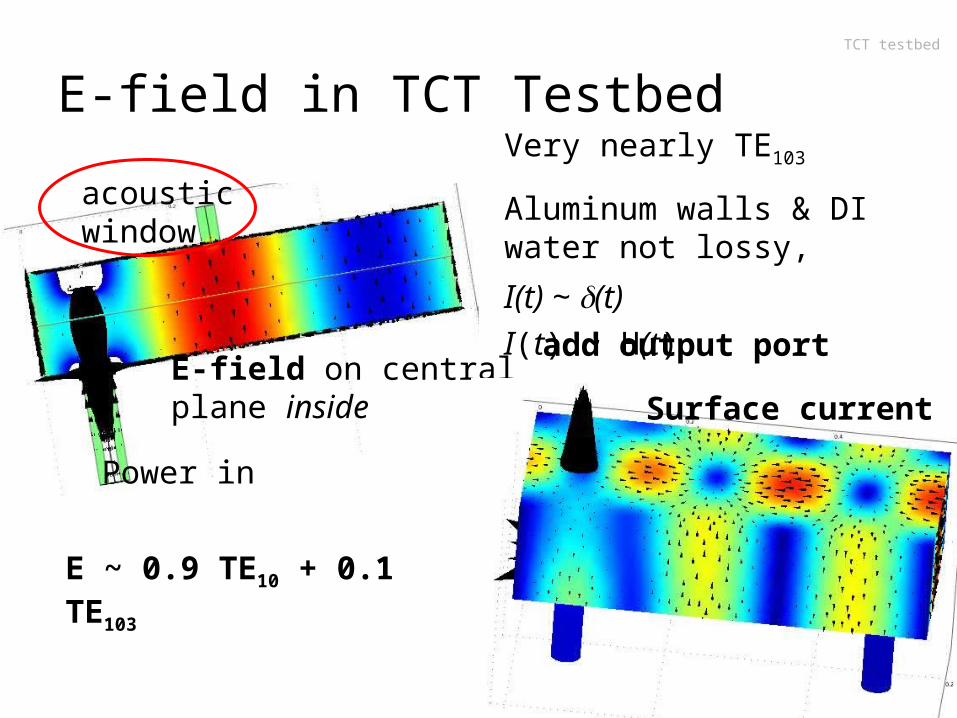
E-field in TCT Testbed
Power in
Very nearly TE103
Aluminum walls & DI water not lossy, waves resonate
I(t) ~ H(t).
acoustic window
E-field on central plane inside Surface current
add output port
E ~ 0.9 TE10 + 0.1 TE103
I(t) ~ (t)
TCT testbed
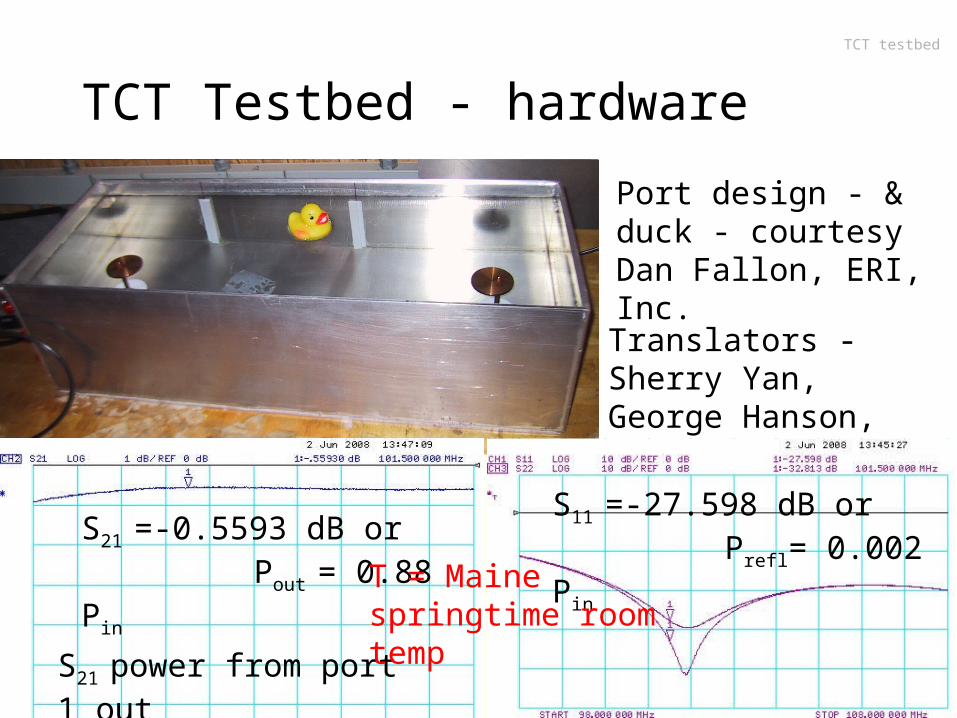
TCT Testbed - hardware
Translators - Sherry Yan, George Hanson, UWM-EE.
Port design - & duck - courtesy Dan Fallon, ERI, Inc.
S21 power from port 1 out port 2
S21 =-0.5593 dB or Pout = 0.88 Pin
S11 =-27.598 dB or Prefl= 0.002 Pin
T = Maine springtime room temp
TCT testbed
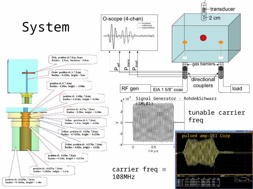
System
Signal Generator - Rohde&Schwarz (SML01)
Pulsed Amplifier - QEI Corp
50kWpulsed amp-QEI Corp
tunable carrier freq
carrier freq 108MHz
TCT testbed
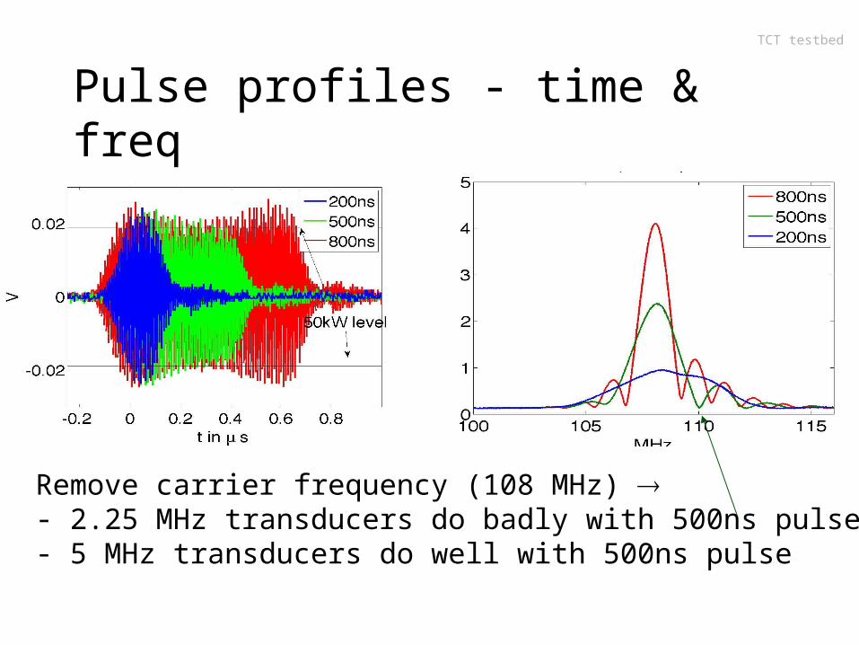
Pulse profiles - time & freq
Remove carrier frequency (108 MHz) - 2.25 MHz transducers do badly with 500ns pulse- 5 MHz transducers do well with 500ns pulse
TCT testbed
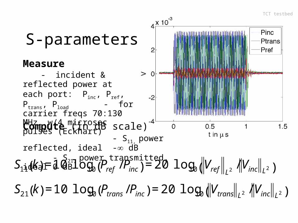
S-parametersMeasure - incident & reflected power at each port: Pinc, Pref, Ptrans, Pload - for carrier freqs 70:130 MHz, w/4 microsec pulses (Eckhart)
Compute (in dB scale) - S11, power reflected, ideal - dB - S21, power transmitted, ideal 0 dB
€
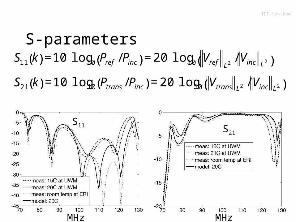
S11 k( ) =10 log10 Pref / Pinc( ) = 20 log10 Vref L2/ Vinc L2( )
S21 k( ) =10 log10 Ptrans / Pinc( ) = 20 log10 Vtrans L2 / Vinc L2( )
TCT testbed
S-parameters
€
S11 k( ) =10 log10 Pref / Pinc( ) = 20 log10 Vref L2/ Vinc L2( )
S21 k( ) =10 log10 Ptrans / Pinc( ) = 20 log10 Vtrans L2 / Vinc L2( )
S11 S21
MHz MHz
TCT testbed
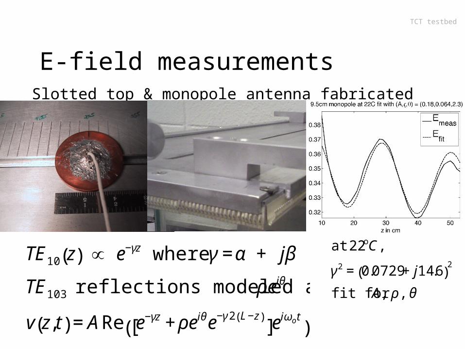
E-field measurements
€
TE10 z( ) ∝ e−γz where γ =α + jβ
TE103 reflections modeled as ρeiθ
v z, t( ) = ARe e−γz + ρeiθe−γ 2 L−z( )[ ]e
iωot( )
Slotted top & monopole antenna fabricated at UWM G. Becker, M Rhodes
€
at 22oC,
γ 2 = 0.0729 + j14.6( )2
fit for A, ρ , θ
TCT testbed
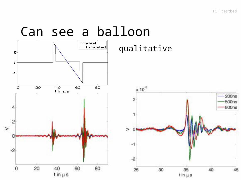
Can see a balloon
qualitative
TCT testbed
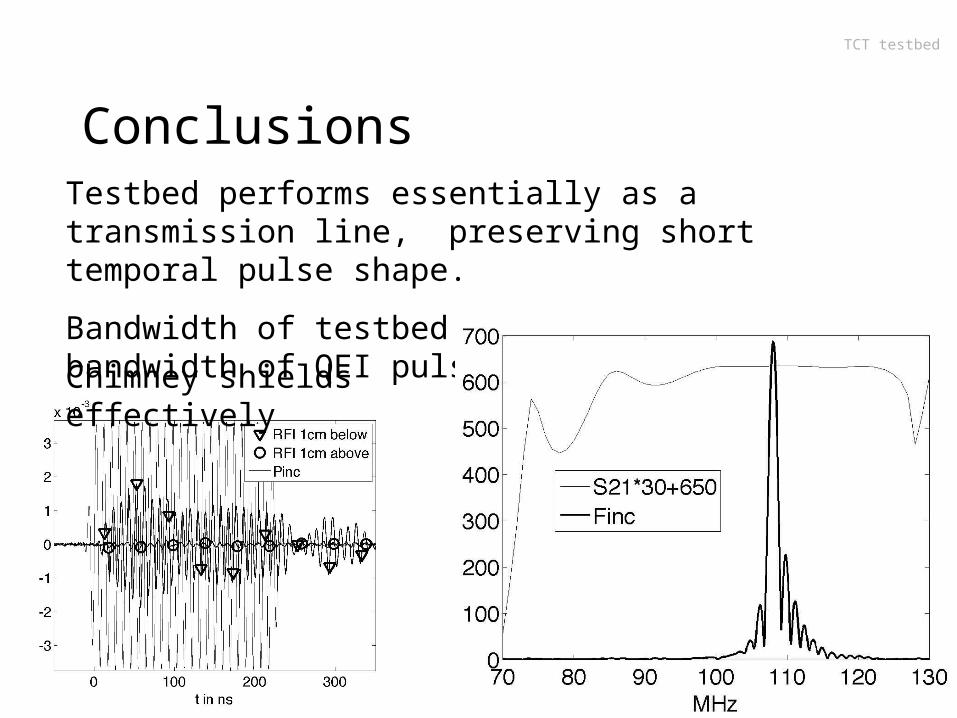
ConclusionsTestbed performs essentially as a transmission line, preserving short temporal pulse shape.
Bandwidth of testbed greater than bandwidth of QEI pulses.
Chimney shields effectively
TCT testbed
Thanks
• WUWM for lending dir coupler line sections• Tom May (WUWM Chief Engineer) for system setup• Andrew Eckhart for collecting S-param data• Mike Schrauth for developing positioners • Mark Rhodes & Jerry Becker for slotted top &
antenna