Embed Size (px)
Citation preview
INST
RU
CT
ION
MA
NU
AL
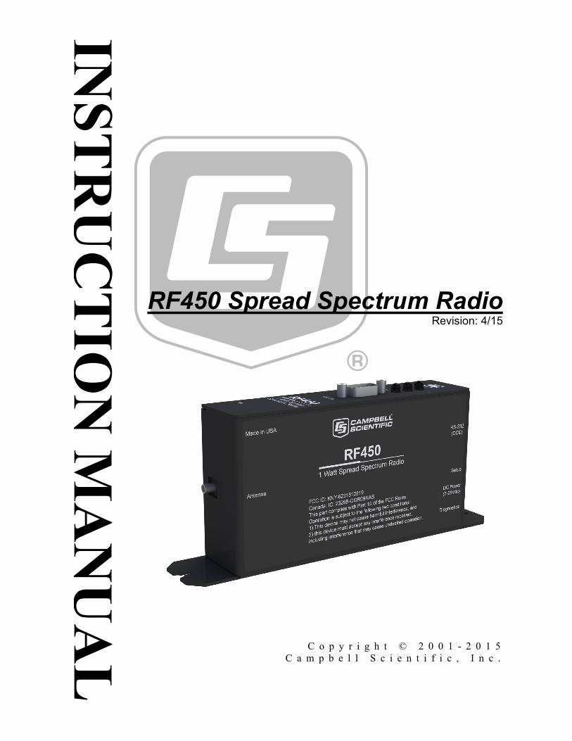
RF450 Spread Spectrum Radio Revision: 4/15
C o p y r i g h t © 2 0 0 1 - 2 0 1 5 C a m p b e l l S c i e n t i f i c , I n c .

Limited Warranty “Products manufactured by CSI are warranted by CSI to be free from defects in materials and workmanship under normal use and service for twelve months from the date of shipment unless otherwise specified in the corresponding product manual. (Product manuals are available for review online at www.campbellsci.com.) Products not manufactured by CSI, but that are resold by CSI, are warranted only to the limits extended by the original manufacturer. Batteries, fine-wire thermocouples, desiccant, and other consumables have no warranty. CSI’s obligation under this warranty is limited to repairing or replacing (at CSI’s option) defective Products, which shall be the sole and exclusive remedy under this warranty. The Customer assumes all costs of removing, reinstalling, and shipping defective Products to CSI. CSI will return such Products by surface carrier prepaid within the continental United States of America. To all other locations, CSI will return such Products best way CIP (port of entry) per Incoterms ® 2010. This warranty shall not apply to any Products which have been subjected to modification, misuse, neglect, improper service, accidents of nature, or shipping damage. This warranty is in lieu of all other warranties, expressed or implied. The warranty for installation services performed by CSI such as programming to customer specifications, electrical connections to Products manufactured by CSI, and Product specific training, is part of CSI's product warranty. CSI EXPRESSLY DISCLAIMS AND EXCLUDES ANY IMPLIED WARRANTIES OF MERCHANTABILITY OR FITNESS FOR A PARTICULAR PURPOSE. CSI hereby disclaims, to the fullest extent allowed by applicable law, any and all warranties and conditions with respect to the Products, whether express, implied or statutory, other than those expressly provided herein.”

Assistance Products may not be returned without prior authorization. The following contact information is for US and international customers residing in countries served by Campbell Scientific, Inc. directly. Affiliate companies handle repairs for customers within their territories. Please visit www.campbellsci.com to determine which Campbell Scientific company serves your country.
To obtain a Returned Materials Authorization (RMA), contact CAMPBELL SCIENTIFIC, INC., phone (435) 227-9000. After an application engineer determines the nature of the problem, an RMA number will be issued. Please write this number clearly on the outside of the shipping container. Campbell Scientific’s shipping address is:
CAMPBELL SCIENTIFIC, INC. RMA#_____ 815 West 1800 North Logan, Utah 84321-1784
For all returns, the customer must fill out a “Statement of Product Cleanliness and Decontamination” form and comply with the requirements specified in it. The form is available from our web site at www.campbellsci.com/repair. A completed form must be either emailed to [email protected] or faxed to (435) 227-9106. Campbell Scientific is unable to process any returns until we receive this form. If the form is not received within three days of product receipt or is incomplete, the product will be returned to the customer at the customer’s expense. Campbell Scientific reserves the right to refuse service on products that were exposed to contaminants that may cause health or safety concerns for our employees.
Precautions DANGER — MANY HAZARDS ARE ASSOCIATED WITH INSTALLING, USING, MAINTAINING, AND WORKING ON OR AROUND TRIPODS, TOWERS, AND ANY ATTACHMENTS TO TRIPODS AND TOWERS SUCH AS SENSORS, CROSSARMS, ENCLOSURES, ANTENNAS, ETC. FAILURE TO PROPERLY AND COMPLETELY ASSEMBLE, INSTALL, OPERATE, USE, AND MAINTAIN TRIPODS, TOWERS, AND ATTACHMENTS, AND FAILURE TO HEED WARNINGS, INCREASES THE RISK OF DEATH, ACCIDENT, SERIOUS INJURY, PROPERTY DAMAGE, AND PRODUCT FAILURE. TAKE ALL REASONABLE PRECAUTIONS TO AVOID THESE HAZARDS. CHECK WITH YOUR ORGANIZATION'S SAFETY COORDINATOR (OR POLICY) FOR PROCEDURES AND REQUIRED PROTECTIVE EQUIPMENT PRIOR TO PERFORMING ANY WORK.
Use tripods, towers, and attachments to tripods and towers only for purposes for which they are designed. Do not exceed design limits. Be familiar and comply with all instructions provided in product manuals. Manuals are available at www.campbellsci.com or by telephoning (435) 227-9000 (USA). You are responsible for conformance with governing codes and regulations, including safety regulations, and the integrity and location of structures or land to which towers, tripods, and any attachments are attached. Installation sites should be evaluated and approved by a qualified engineer. If questions or concerns arise regarding installation, use, or maintenance of tripods, towers, attachments, or electrical connections, consult with a licensed and qualified engineer or electrician. General
• Prior to performing site or installation work, obtain required approvals and permits. Comply with all governing structure-height regulations, such as those of the FAA in the USA.
• Use only qualified personnel for installation, use, and maintenance of tripods and towers, and any attachments to tripods and towers. The use of licensed and qualified contractors is highly recommended.
• Read all applicable instructions carefully and understand procedures thoroughly before beginning work.
• Wear a hardhat and eye protection, and take other appropriate safety precautions while working on or around tripods and towers.
• Do not climb tripods or towers at any time, and prohibit climbing by other persons. Take reasonable precautions to secure tripod and tower sites from trespassers.
• Use only manufacturer recommended parts, materials, and tools.
Utility and Electrical • You can be killed or sustain serious bodily injury if the tripod, tower, or attachments you are
installing, constructing, using, or maintaining, or a tool, stake, or anchor, come in contact with overhead or underground utility lines.
• Maintain a distance of at least one-and-one-half times structure height, 20 feet, or the distance required by applicable law, whichever is greater, between overhead utility lines and the structure (tripod, tower, attachments, or tools).
• Prior to performing site or installation work, inform all utility companies and have all underground utilities marked.
• Comply with all electrical codes. Electrical equipment and related grounding devices should be installed by a licensed and qualified electrician.
Elevated Work and Weather • Exercise extreme caution when performing elevated work. • Use appropriate equipment and safety practices. • During installation and maintenance, keep tower and tripod sites clear of un-trained or non-
essential personnel. Take precautions to prevent elevated tools and objects from dropping. • Do not perform any work in inclement weather, including wind, rain, snow, lightning, etc.
Maintenance • Periodically (at least yearly) check for wear and damage, including corrosion, stress cracks,
frayed cables, loose cable clamps, cable tightness, etc. and take necessary corrective actions. • Periodically (at least yearly) check electrical ground connections.
WHILE EVERY ATTEMPT IS MADE TO EMBODY THE HIGHEST DEGREE OF SAFETY IN ALL CAMPBELL SCIENTIFIC PRODUCTS, THE CUSTOMER ASSUMES ALL RISK FROM ANY INJURY RESULTING FROM IMPROPER INSTALLATION, USE, OR MAINTENANCE OF TRIPODS, TOWERS, OR ATTACHMENTS TO TRIPODS AND TOWERS SUCH AS SENSORS, CROSSARMS, ENCLOSURES, ANTENNAS, ETC.

Table of Contents PDF viewers: These page numbers refer to the printed version of this document. Use the PDF reader bookmarks tab for links to specific sections.
1. General Description .................................................... 1
2. Cautionary Statements ............................................... 1
3. Specifications ............................................................. 1
4. Configuration .............................................................. 2
4.1 Theory of Radio Operation .................................................................. 2 4.2 PakBus Graph ...................................................................................... 3 4.3 Location of the Transceivers ................................................................ 4 4.4 Using the Device Configuration Utility ............................................... 4 4.5 Quick Start ........................................................................................... 7 4.6 Deployment Settings ............................................................................ 8
4.6.1 Active Interface ............................................................................. 8 4.6.2 SDC Address................................................................................. 8 4.6.3 Baud Rate ...................................................................................... 8 4.6.4 RF450 Operation Mode Setting .................................................... 9
4.6.4.1 Operation Mode Description .............................................. 9 4.6.5 Network ID ................................................................................. 10 4.6.6 Frequency Key Setting ................................................................ 10 4.6.7 Repeater Frequency Key Setting ................................................. 10 4.6.8 Transmit Power Setting ............................................................... 10 4.6.9 Low Power Mode Setting ........................................................... 11 4.6.10 Transmit Subnet ID Setting ........................................................ 12 4.6.11 Radio ID Setting ......................................................................... 12
4.7 Master Radio ...................................................................................... 13 4.8 Slave ................................................................................................... 14 4.9 Repeater ............................................................................................. 14 4.10 Power Considerations ........................................................................ 15
5. Antennas ................................................................... 15
5.1 Antennas for the RF450 Series .......................................................... 15 5.2 Antenna Cables and Surge Protection ................................................ 17
5.2.1 Antenna Cables ........................................................................... 17 5.2.2 Electrostatic Issues ...................................................................... 17 5.2.3 Antenna Surge Protector Kit ....................................................... 17
6. LoggerNet Software Setup ....................................... 18
7. RF450s with RF401 or CR206(X) in the Same Network ................................................................... 19
8. Troubleshooting........................................................ 19
i
Table of Contents
Appendix
A. Installation Scenarios ............................................. A-1
A.1 Example 1: PC-to-RF Network ...................................................... A-1 A.2 Example 2: PC-to-RF Network with Repeater ............................... A-3 A.3 Example 3: PC-to-RF Network with Parallel Repeaters (using
the SubNet ID) ............................................................................. A-5 A.4 Example 4: Phone-to-RF Base ....................................................... A-7 A.5 Example 5: Call-back ..................................................................... A-8
Appendix B. Settings Editor ...................................... B-1
Figures 4-1. Simplest Form of a Multi-Point Network ............................................ 3 4-2. Point to Multi-Point Network with Two Routers ................................ 3 4-3. RF450 Point to Multi-Point Network with Two Routers as
Displayed in PakBus Graph ............................................................. 4 4-4. Start-up DevConfig Screen for Configuring the RF450 ...................... 5 4-5. DevConfig Screen Showing the RF450 Settings ................................. 6 4-6. DevConfig RF450 Summary Screen ................................................... 7 4-7. DevConfig Screen Showing Settings for Multi-Point Master ............ 13 4-8. DevConfig Screen Showing Settings for a Slave in a Multi-Point
Network ......................................................................................... 14 4-9. DevConfig Screen Showing Settings for Repeater in a Multi-Point
Network ......................................................................................... 14 6-1. LoggerNet Setup Screen for an RF450 Multi-Point Network ........... 18 8-1. RF450 Front Side View ..................................................................... 19 A-1. Schematic of PC-to-RF450 Network ............................................... A-1 A-2. DevConfig Screen Showing Master Radio Settings for
Example 1 .................................................................................... A-2 A-3. Schematic of PC-to-RF450 Network with Repeater ....................... A-3 A-4. DevConfig Screen Showing Master Radio Settings for
Example 2 .................................................................................... A-4 A-5. DevConfig Screen Showing Slave/Repeater Radio Settings for
Example 2 .................................................................................... A-4 A-6. DevConfig Screen Showing Slave Radio Settings for
Example 2 .................................................................................... A-5 A-7. Schematic of PC-to-RF Network with Parallel Repeaters (using
the SubNet ID) ............................................................................. A-6 A-8. Schematic of Phone-to-RF Base ...................................................... A-7
Tables 4-1. Transmit Power Settings ................................................................... 11 4-2. Low Power Mode Settings ................................................................ 12 4-3. Power Requirements at 12 VDC ....................................................... 15 8-1. Multi-Point Network LED Status ...................................................... 19 A-1. RF450 Settings for Example 1 ........................................................ A-2 A-2. RF450 Settings for Example 2 ........................................................ A-3 A-3. RF450 Settings for Example 3 ........................................................ A-6 A-4. RF450 Settings for Example 4 ........................................................ A-7
ii
FCC Notifications This device complies with part 15 of the FCC rules. Operation is subject to the following two conditions: 1) This device may not cause harmful interference and 2) this device must accept any interference received, including interference that may cause undesired operation. This device must be operated as supplied by Campbell Scientific, Inc. Any changes or modifications made to the device without the express written approval of Campbell Scientific, Inc may void the user's authority to operate the device.
The module number FGR09 has a maximum transmitted output power of 955mW. It is recommended that the transmit antenna be kept at least 23cm (approximately 10 inches) away from nearby persons to satisfy FCC RF exposure requirements.
This equipment has been tested and found to comply with the limits for a Class B digital device, pursuant to part 15 of the FCC Rules. These limits are designed to provide reasonable protection against harmful interference in a residential installation. This equipment generates, uses, and can radiate radio frequency energy and, if not installed and used in accordance with the instructions, may cause harmful interference to radio communications. However, there is no guarantee that interference will not occur in a particular installation. If this equipment does cause harmful interference to radio or television reception, which can be determined by turning the equipment off and on, the user is encouraged to try to correct the interference by one or more of the following measures:
• Reorient or relocate the receiving antenna
• Increase the separation between the equipment and receiver
• Connect the equipment into an outlet on a circuit different from that to which the receiver is connected
• Consult an experienced radio/TV technician for help
• Consult Campbell Scientific
CAUTION

RF450 Spread Spectrum Radio 1. General Description
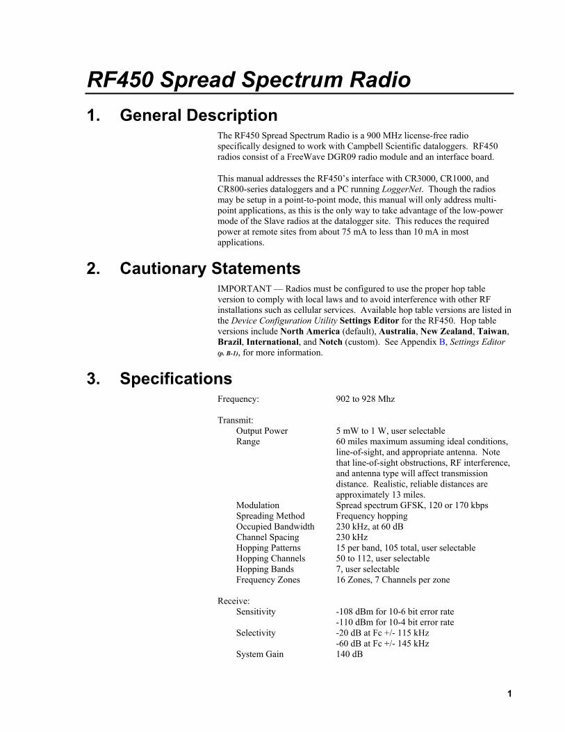
The RF450 Spread Spectrum Radio is a 900 MHz license-free radio specifically designed to work with Campbell Scientific dataloggers. RF450 radios consist of a FreeWave DGR09 radio module and an interface board.
This manual addresses the RF450’s interface with CR3000, CR1000, and CR800-series dataloggers and a PC running LoggerNet. Though the radios may be setup in a point-to-point mode, this manual will only address multi-point applications, as this is the only way to take advantage of the low-power mode of the Slave radios at the datalogger site. This reduces the required power at remote sites from about 75 mA to less than 10 mA in most applications.
2. Cautionary Statements IMPORTANT — Radios must be configured to use the proper hop table version to comply with local laws and to avoid interference with other RF installations such as cellular services. Available hop table versions are listed in the Device Configuration Utility Settings Editor for the RF450. Hop table versions include North America (default), Australia, New Zealand, Taiwan, Brazil, International, and Notch (custom). See Appendix B, Settings Editor (p. B-1), for more information.
3. Specifications Frequency: 902 to 928 Mhz Transmit: Output Power 5 mW to 1 W, user selectable Range 60 miles maximum assuming ideal conditions, line-of-sight, and appropriate antenna. Note that line-of-sight obstructions, RF interference, and antenna type will affect transmission distance. Realistic, reliable distances are approximately 13 miles. Modulation Spread spectrum GFSK, 120 or 170 kbps Spreading Method Frequency hopping Occupied Bandwidth 230 kHz, at 60 dB Channel Spacing 230 kHz Hopping Patterns 15 per band, 105 total, user selectable Hopping Channels 50 to 112, user selectable Hopping Bands 7, user selectable Frequency Zones 16 Zones, 7 Channels per zone Receive: Sensitivity -108 dBm for 10-6 bit error rate -110 dBm for 10-4 bit error rate Selectivity -20 dB at Fc +/- 115 kHz -60 dB at Fc +/- 145 kHz System Gain 140 dB
1
RF450 Spread Spectrum Radio
Data Transmission: Error Detection 32 bit CRC, retransmit on error Data Encryption Substitution, dynamic key Link Throughput 115.2 kbps, max Data Interface: Protocol RS-232, DCE, CS I/O, ME, and SDC; user selectable RS-232 Baud Rate: 1200 bps, 4800 bps, 9600 bps, 19.2 kbps, 38.4 kbps, 57.6 kbps, 115.2 kbps; user selectable Connectors DB9 Antenna SMA female connector External antenna required Power Requirements: Voltage 7 to 28 Vdc Current Transmit 500 mA Receive 76 mA* Idle 22 mA* Sleep 7 mA* Environmental: Operating Temperature -40° to +75°C Dimensions 1.44” x 3.17” x 5.70” (3.66 x 8.05 x 14.48 cm) 1.44” x 3.17” x 7.5” (3.66 x 8.05 x 19.05 cm) with
mounting plate Weight 0.7 lbs (0.3 kg) Humidity 0 to 95% non-condensing FCC ID: KNY-6231812519 Canada: 2329B-DGR09RAS
4. Configuration 4.1 Theory of Radio Operation
In a point-to-multi-point network (multi-point network) the transceiver designated as a Master, is able to simultaneously communicate with numerous Slaves. In its simplest form, a multi-point network functions with the Master broadcasting its messages to all Slaves and the Slaves responding to the Master when given data by the datalogger connected to the data port (see FIGURE 4-1).
There may be only one RF450 Master in a network and it must be connected to a PakBus router. A PakBus router may be software such as LoggerNet or PC400 or a datalogger configured as a router.
NOTE
2
RF450 Spread Spectrum Radio
Master
Slave
Slave
Slave
FIGURE 4-1. Simplest Form of a Multi-Point Network
In a multi-point network, outbound packets from the Master or repeater to Slaves or other repeaters are sent a set number of times determined by the user. The receiving transceiver, Slave or repeater, will accept the first packet received with the correct signature (32 bit CRC). However, the packet is not acknowledged. On the return trip to the Master, all packets sent are acknowledged or retransmitted until they are acknowledged. Therefore, the return link in a multi-point network is generally very robust.
Traditionally, a multi-point network is used in applications where data is collected from one to many dataloggers and reported back to one central site. The central site is typically a PC running LoggerNet, but could be a datalogger. Refer to Appendix A, Installation Scenarios (p. A-1), for different installation scenarios.
Though the radios may be setup in a point-to-point mode, this manual will only address multi-point applications, as this is the only way to take advantage of the low-power mode of the Slave radios at the datalogger site. This reduces the required power at remote sites from about 75mA to less than 10mA in most applications.
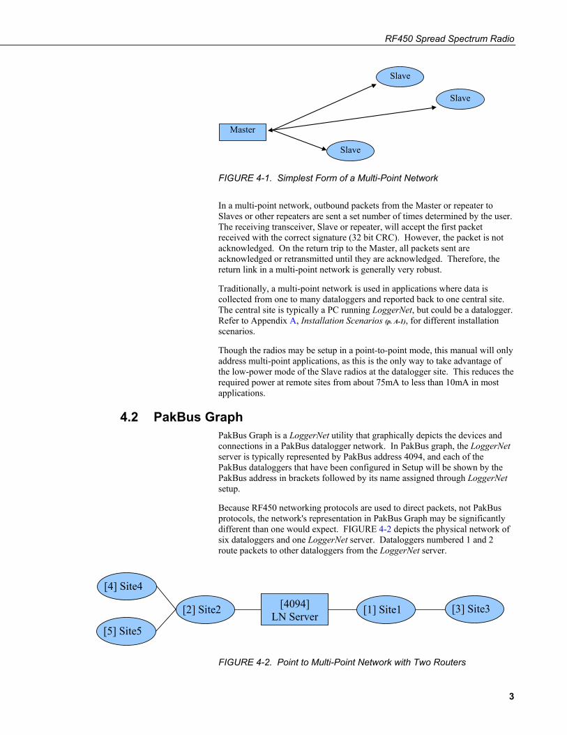
4.2 PakBus Graph PakBus Graph is a LoggerNet utility that graphically depicts the devices and connections in a PakBus datalogger network. In PakBus graph, the LoggerNet server is typically represented by PakBus address 4094, and each of the PakBus dataloggers that have been configured in Setup will be shown by the PakBus address in brackets followed by its name assigned through LoggerNet setup.
Because RF450 networking protocols are used to direct packets, not PakBus protocols, the network's representation in PakBus Graph may be significantly different than one would expect. FIGURE 4-2 depicts the physical network of six dataloggers and one LoggerNet server. Dataloggers numbered 1 and 2 route packets to other dataloggers from the LoggerNet server.
[4] Site4
[5] Site5
[2] Site2 [4094] LN Server [1] Site1 [3] Site3
FIGURE 4-2. Point to Multi-Point Network with Two Routers
3
RF450 Spread Spectrum Radio
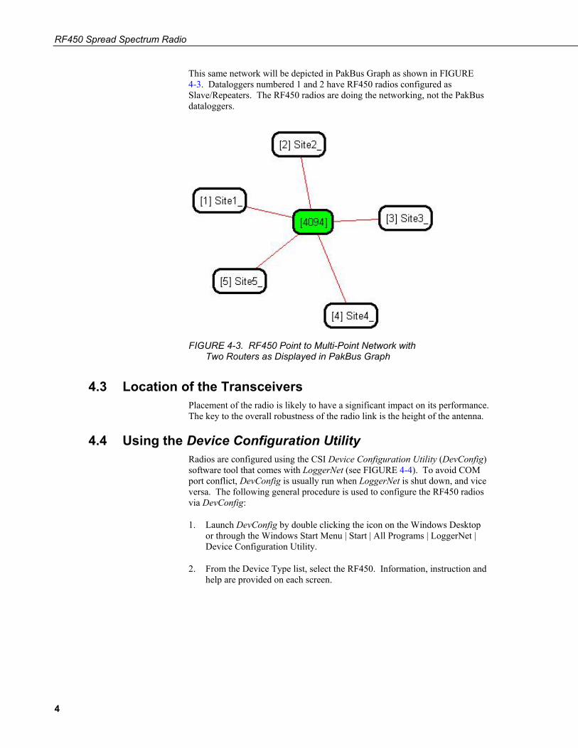
This same network will be depicted in PakBus Graph as shown in FIGURE 4-3. Dataloggers numbered 1 and 2 have RF450 radios configured as Slave/Repeaters. The RF450 radios are doing the networking, not the PakBus dataloggers.
FIGURE 4-3. RF450 Point to Multi-Point Network with Two Routers as Displayed in PakBus Graph
4.3 Location of the Transceivers Placement of the radio is likely to have a significant impact on its performance. The key to the overall robustness of the radio link is the height of the antenna.
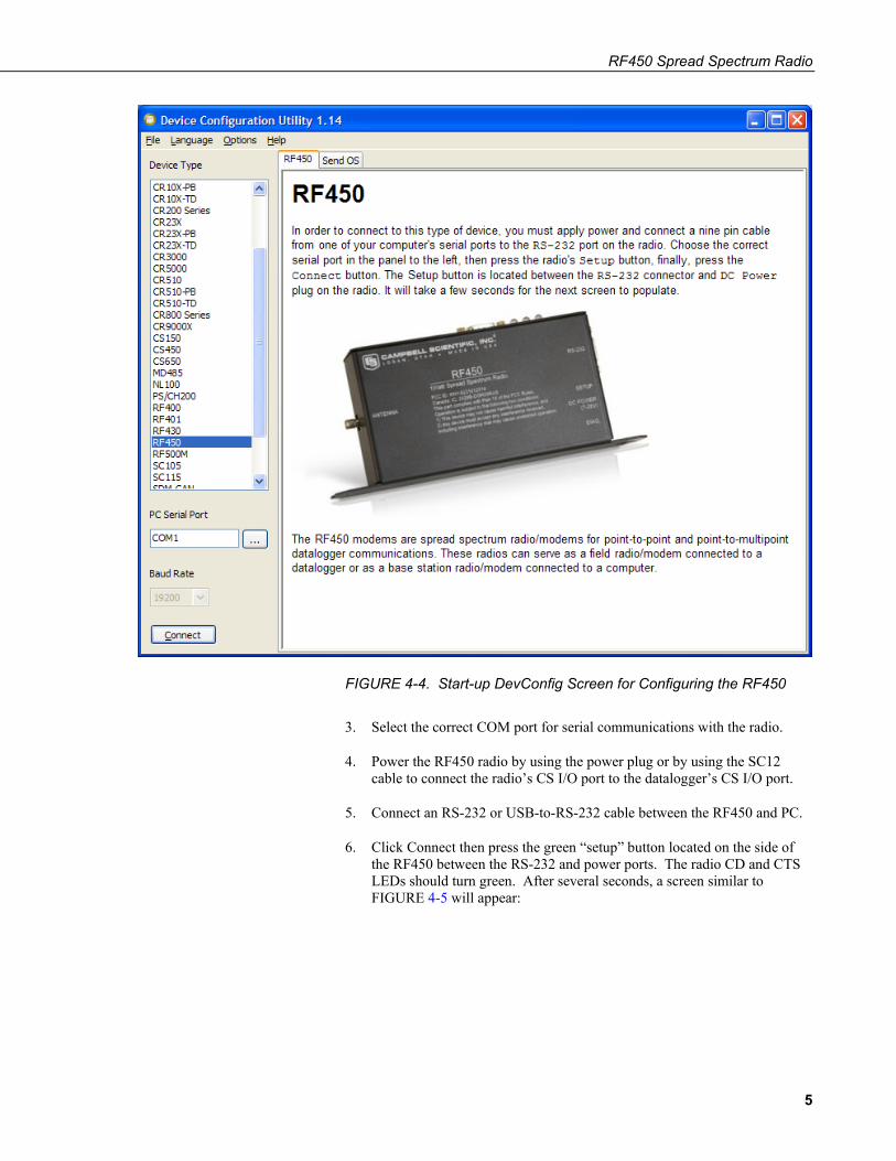
4.4 Using the Device Configuration Utility Radios are configured using the CSI Device Configuration Utility (DevConfig) software tool that comes with LoggerNet (see FIGURE 4-4). To avoid COM port conflict, DevConfig is usually run when LoggerNet is shut down, and vice versa. The following general procedure is used to configure the RF450 radios via DevConfig:
1. Launch DevConfig by double clicking the icon on the Windows Desktop or through the Windows Start Menu | Start | All Programs | LoggerNet | Device Configuration Utility.
2. From the Device Type list, select the RF450. Information, instruction and help are provided on each screen.
4
RF450 Spread Spectrum Radio
FIGURE 4-4. Start-up DevConfig Screen for Configuring the RF450
3. Select the correct COM port for serial communications with the radio.
4. Power the RF450 radio by using the power plug or by using the SC12 cable to connect the radio’s CS I/O port to the datalogger’s CS I/O port.
5. Connect an RS-232 or USB-to-RS-232 cable between the RF450 and PC.
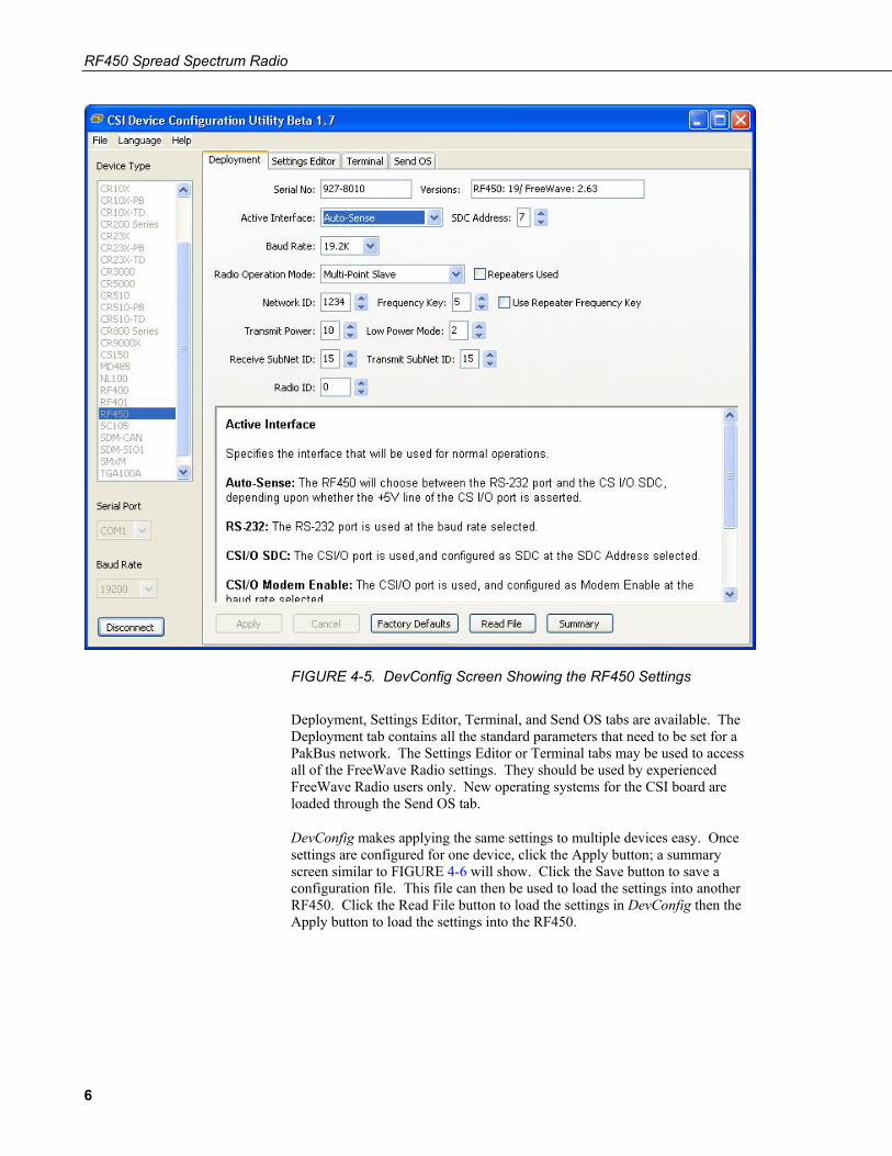
6. Click Connect then press the green “setup” button located on the side of the RF450 between the RS-232 and power ports. The radio CD and CTS LEDs should turn green. After several seconds, a screen similar to FIGURE 4-5 will appear:
5
RF450 Spread Spectrum Radio
FIGURE 4-5. DevConfig Screen Showing the RF450 Settings
Deployment, Settings Editor, Terminal, and Send OS tabs are available. The Deployment tab contains all the standard parameters that need to be set for a PakBus network. The Settings Editor or Terminal tabs may be used to access all of the FreeWave Radio settings. They should be used by experienced FreeWave Radio users only. New operating systems for the CSI board are loaded through the Send OS tab.
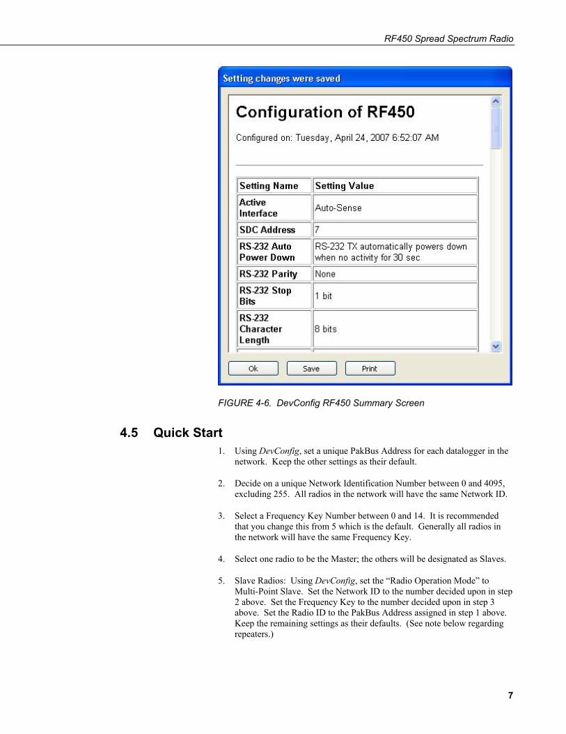
DevConfig makes applying the same settings to multiple devices easy. Once settings are configured for one device, click the Apply button; a summary screen similar to FIGURE 4-6 will show. Click the Save button to save a configuration file. This file can then be used to load the settings into another RF450. Click the Read File button to load the settings in DevConfig then the Apply button to load the settings into the RF450.
6
RF450 Spread Spectrum Radio
FIGURE 4-6. DevConfig RF450 Summary Screen
4.5 Quick Start 1. Using DevConfig, set a unique PakBus Address for each datalogger in the
network. Keep the other settings as their default.
2. Decide on a unique Network Identification Number between 0 and 4095, excluding 255. All radios in the network will have the same Network ID.
3. Select a Frequency Key Number between 0 and 14. It is recommended that you change this from 5 which is the default. Generally all radios in the network will have the same Frequency Key.
4. Select one radio to be the Master; the others will be designated as Slaves.
5. Slave Radios: Using DevConfig, set the “Radio Operation Mode” to Multi-Point Slave. Set the Network ID to the number decided upon in step 2 above. Set the Frequency Key to the number decided upon in step 3 above. Set the Radio ID to the PakBus Address assigned in step 1 above. Keep the remaining settings as their defaults. (See note below regarding repeaters.)
7
RF450 Spread Spectrum Radio
6. Master Radio: Using DevConfig, set the “Radio Operation Mode” to Multi-Point Master. Set the Network ID to the number decided upon in step 2 above. Set the Frequency Key to the number decided upon in step 3 above. Set the Radio ID to the PakBus Address assigned in step 1 above. Keep the remaining settings as their defaults. (See note below regarding repeaters.)
7. Select a datalogger, or PC running LoggerNet, to be a router. Using DevConfig, set this node to beacon. Attach the Master Radio to this node.
If RF450 repeaters will be used, select Multi-Point Slave/Repeater as the Radio Operation Mode. Check the “Repeaters Used” box for all radios in the Network.
4.6 Deployment Settings See Appendix A, Installation Scenarios (p. A-1), for example radio settings in different network configurations.
4.6.1 Active Interface Specify the interface that will be used for normal operations. The following active interfaces are available:
• Auto-Sense: The RF450 will choose between the RS-232 port and the CS I/O SDC, depending upon whether the +5 V line of the CS I/O port is present.
• RS-232: The RS-232 port is used at the baud rate selected.
• CS I/O SDC: The CS I/O port is used, and configured as SDC at the SDC Address selected.
• CS I/O Modem Enable: The CS I/O port is used, and configured as Modem Enable at the baud rate selected.
• ME Master: The CS I/O port is used, and configured for direct connection to a CSI COM200, COM210, COM220, or other ME configured device (MD485, RF416, etc.). The connection is a type of "null modem" that crosses TX & RX, and ME & RING; this line swapping is done by using an A100. The baud rates of both the COM2xx (or other device) and RF450 must be the same.
4.6.2 SDC Address Specifies the SDC address that will be used on the RF450 CS I/O port when CS I/O SDC or Auto-Sense is selected as the active interface.
4.6.3 Baud Rate Specifies the baud rate that will be used on the RS-232 port or CS I/O ME port.
NOTE
NOTE
8
RF450 Spread Spectrum Radio
4.6.4 RF450 Operation Mode Setting The Operation Mode option designates the method FreeWave transceivers use to communicate with each other. FreeWave transceivers operate in a Master-to-Slave configuration. Before the transceivers can operate together, they must be set up to properly communicate.
In a point-to-point configuration, Master or Slave mode may be used on either end of the communication link without performance degradation. When setting up the transceiver, remember that a number of parameters are controlled by the settings in the Master. Also, radio network diagnostics can only be accessed at the Master radio. Therefore, we suggest you deploy the Master on the communications end where it will be easier to access.
For a datalogger PakBus network, the multi-point radio modes should be used. For other configurations, the Operation Mode will need to be set through the Settings Editor tab.
4.6.4.1 Operation Mode Description
Point-to-MultiPoint Master
This mode designates the transceiver as a Master in multi-point mode. This mode allows one Master transceiver to simultaneously be in communication with numerous Slaves and repeaters. A point-to-multi-point Master communicates only with other transceivers designated as point-to-multipoint Slaves or point-to-multipoint repeaters.
Point-to-MultiPoint Slave
This mode designates the transceiver as a Slave in multi-point mode. This mode allows the Slave to communicate with a multi-point Master. The Slave may communicate with its Master through one or more repeaters.
Point-to-MultiPoint Repeater
This option allows the transceiver to operate as a repeater in a multi-point network.
Point-to-MultiPoint Slave/Repeater
This option allows the transceiver to operate as a repeater and a Slave in a multi-point network. The radio will repeat packets sent across the network as well as use the active interface. Choosing this setting effectively sets the operation mode to multi-point repeater and sets the Slave/repeater mode.
Repeaters Used Setting
In a multi-point network, it is critical to transmission timing to configure this parameter correctly. This box should be checked (set to 1 in Settings Editor) if there are any repeaters in the network. It should be left unchecked (set to 0 in Settings Editor) if there are no repeaters present.
This parameter should be set to the same value in all transceivers in a multi-point network.
9
RF450 Spread Spectrum Radio
This box should be checked (set to 1 in Settings Editor) when running diagnostics from the Master.
4.6.5 Network ID All radios in a multi-point network need to have the same Network ID. The value must be between 0 and 4095 (excluding 255). The ID of 255 is reserved for point-to-point networks.
Slaves will link with the first Master or repeater that it hears with a matching Network ID. Assigning a unique Network ID will reduce the chance a radio in your network links with another, unrelated, network in the same RF area.
If necessary, the Network ID function can be used in conjunction with the SubNet ID feature.
4.6.6 Frequency Key Setting The Frequency Key determines the frequency hopping sequence of the transceiver. There are 15 choices available (0-14) which represent 15 unique pseudo-random hop patterns. This setting allows you to minimize RF interference with other FreeWave transceivers operating in the same RF area.
The Frequency Key setting should be the same for all radios in the entire network. The exception to this is if the Repeater Frequency Key setting is used. If this is used, the Repeaters' Frequency Key would be different from the Master radio, and downstream radios intended to connect to the repeater would have the same Frequency Key setting (as the repeater).
4.6.7 Repeater Frequency Key Setting This is a setting that is only used by repeaters. The Repeater Frequency Key must be checked when you want a repeater to use a Frequency Key other than that of the Master.
This is useful when there are parallel repeaters in a network, and you want to force communication through a particular repeater. When this setting is used, the repeater will receive on the Frequency Key of the upstream Master (or repeater), and transmit on its Frequency Key setting (which typically is set to a different value than the Master’s).
The default setting of box not checked (Use Master Frequency) causes the repeater to transmit on the Master’s Frequency Key.
When this setting is not used, the Frequency Key setting should match that of the Master or of the repeater acting as the Master for that transceiver.
4.6.8 Transmit Power Setting This setting specifies the RF transmit power. Use a transmit power of 0 when bench testing to reduce RF exposure.
NOTE
NOTE
NOTE
10
RF450 Spread Spectrum Radio
The FCC specifies a maximum EIRP (Effective Isotropic Radiated Power) of 36 dBm.
EIRP = (Transmitter Power) + (Antenna Gain) - (Cable Losses) [all in dB or dBm]
The RF450 maximum power is 30.5 dBm; therefore, a 6 dB (or lower) gain antenna can be used with any Transmit Power setting. If higher gain antennas are used, the cable loss will need to be determined, and the Transmit Power adjusted so as not to exceed the FCC limit of 36 dBm.
Note that lower transmit power can be used (to conserve battery power) if the required range allows it.
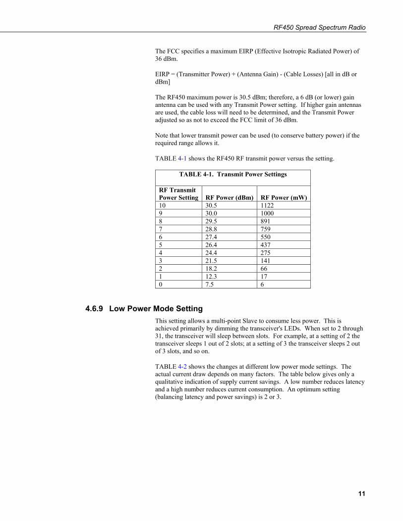
TABLE 4-1 shows the RF450 RF transmit power versus the setting.
TABLE 4-1. Transmit Power Settings
RF Transmit Power Setting
RF Power (dBm)
RF Power (mW)
10 30.5 1122 9 30.0 1000 8 29.5 891 7 28.8 759 6 27.4 550 5 26.4 437 4 24.4 275 3 21.5 141 2 18.2 66 1 12.3 17 0 7.5 6
4.6.9 Low Power Mode Setting This setting allows a multi-point Slave to consume less power. This is achieved primarily by dimming the transceiver's LEDs. When set to 2 through 31, the transceiver will sleep between slots. For example, at a setting of 2 the transceiver sleeps 1 out of 2 slots; at a setting of 3 the transceiver sleeps 2 out of 3 slots, and so on.
TABLE 4-2 shows the changes at different low power mode settings. The actual current draw depends on many factors. The table below gives only a qualitative indication of supply current savings. A low number reduces latency and a high number reduces current consumption. An optimum setting (balancing latency and power savings) is 2 or 3.
11
RF450 Spread Spectrum Radio
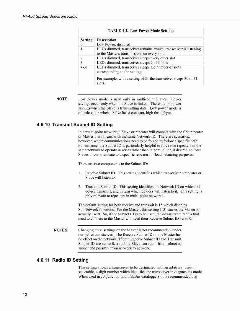
TABLE 4-2. Low Power Mode Settings
Setting Description 0 Low Power, disabled 1 LEDs dimmed, transceiver remains awake, transceiver is listening
to the Master's transmissions on every slot. 2 LEDs dimmed, transceiver sleeps every other slot 3 LEDs dimmed, transceiver sleeps 2 of 3 slots 4-31 LEDs dimmed, transceiver sleeps the number of slots
corresponding to the setting.
For example, with a setting of 31 the transceiver sleeps 30 of 31 slots.
Low power mode is used only in multi-point Slaves. Power savings occur only when the Slave is linked. There are no power savings when the Slave is transmitting data. Low power mode is of little value when a Slave has a constant, high throughput.
4.6.10 Transmit Subnet ID Setting In a multi-point network, a Slave or repeater will connect with the first repeater or Master that it hears with the same Network ID. There are scenarios, however, where communications need to be forced to follow a specific path. For instance, the Subnet ID is particularly helpful to force two repeaters in the same network to operate in series rather than in parallel; or, if desired, to force Slaves to communicate to a specific repeater for load balancing purposes.
There are two components to the Subnet ID:
1. Receive Subnet ID. This setting identifies which transceiver a repeater or Slave will listen to.
2. Transmit Subnet ID. This setting identifies the Network ID on which this device transmits, and in turn which devices will listen to it. This setting is only relevant to repeaters in multi-point networks.
The default setting for both receive and transmit is 15 which disables SubNetwork functions. For the Master, this setting (15) causes the Master to actually use 0. So, if the Subnet ID is to be used, the downstream radios that need to connect to the Master will need their Receive Subnet ID set to 0.
Changing these settings on the Master is not recommended, under normal circumstances. The Receive Subnet ID on the Master has no effect on the network. If both Receive Subnet ID and Transmit Subnet ID are set to 0, a mobile Slave can roam from subnet to subnet and possibly from network to network.
4.6.11 Radio ID Setting This setting allows a transceiver to be designated with an arbitrary, user-selectable, 4-digit number which identifies the transceiver in diagnostics mode. When used in conjunction with PakBus dataloggers, it is recommended that
NOTE
NOTES
12
RF450 Spread Spectrum Radio
this value be assigned the PakBus address of the station. This is because the radio ID appears in the FreeWave diagnostics program, and allows the user to associate a particular datalogger with its attached radio.
To further this association of the RF450 RF network with the PakBus network, the dataloggers (CR1000, CR800, etc.) read the serial number of the attached radio and include this in the datalogger settings when the CS I/O SDC interface is used. This serial number is the main radio identifier used by the FreeWave Diagnostics program.
4.7 Master Radio A multi-point network may only contain a single Master radio. Slave radios communicate from and to the Master radio.
The Master RF450 must be connected to a PakBus router. A PakBus router may be software such as LoggerNet or PC400 or a datalogger configured as a router.
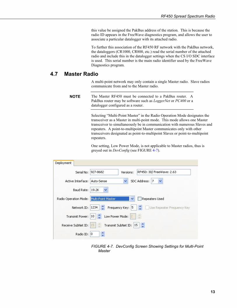
Selecting “Multi-Point Master” in the Radio Operation Mode designates the transceiver as a Master in multi-point mode. This mode allows one Master transceiver to simultaneously be in communication with numerous Slaves and repeaters. A point-to-multipoint Master communicates only with other transceivers designated as point-to-multipoint Slaves or point-to-multipoint repeaters.
One setting, Low Power Mode, is not applicable to Master radios, thus is greyed out in DevConfig (see FIGURE 4-7).
FIGURE 4-7. DevConfig Screen Showing Settings for Multi-Point Master
NOTE
13
RF450 Spread Spectrum Radio
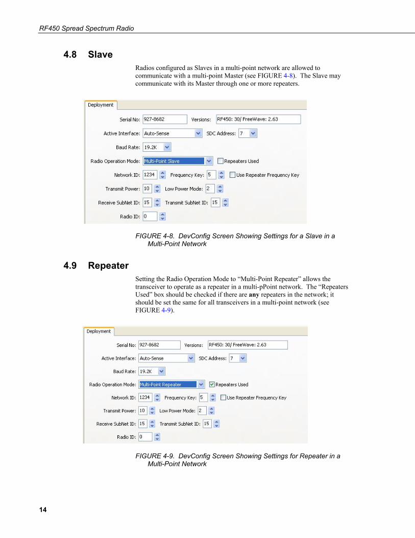
4.8 Slave Radios configured as Slaves in a multi-point network are allowed to communicate with a multi-point Master (see FIGURE 4-8). The Slave may communicate with its Master through one or more repeaters.
FIGURE 4-8. DevConfig Screen Showing Settings for a Slave in a Multi-Point Network
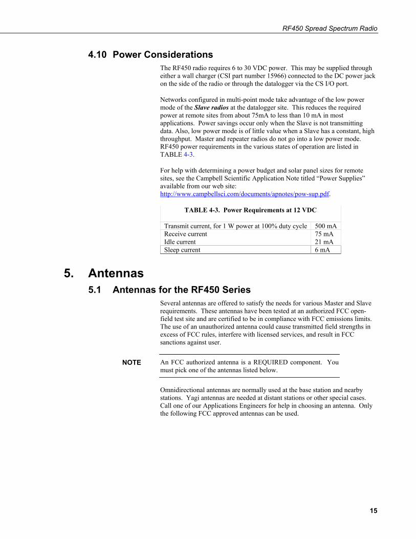
4.9 Repeater Setting the Radio Operation Mode to “Multi-Point Repeater” allows the transceiver to operate as a repeater in a multi-pPoint network. The “Repeaters Used” box should be checked if there are any repeaters in the network; it should be set the same for all transceivers in a multi-point network (see FIGURE 4-9).
FIGURE 4-9. DevConfig Screen Showing Settings for Repeater in a Multi-Point Network
14
RF450 Spread Spectrum Radio
4.10 Power Considerations The RF450 radio requires 6 to 30 VDC power. This may be supplied through either a wall charger (CSI part number 15966) connected to the DC power jack on the side of the radio or through the datalogger via the CS I/O port.
Networks configured in multi-point mode take advantage of the low power mode of the Slave radios at the datalogger site. This reduces the required power at remote sites from about 75mA to less than 10 mA in most applications. Power savings occur only when the Slave is not transmitting data. Also, low power mode is of little value when a Slave has a constant, high throughput. Master and repeater radios do not go into a low power mode. RF450 power requirements in the various states of operation are listed in TABLE 4-3.
For help with determining a power budget and solar panel sizes for remote sites, see the Campbell Scientific Application Note titled “Power Supplies” available from our web site: http://www.campbellsci.com/documents/apnotes/pow-sup.pdf.
TABLE 4-3. Power Requirements at 12 VDC
Transmit current, for 1 W power at 100% duty cycle 500 mA Receive current 75 mA Idle current 21 mA Sleep current 6 mA
5. Antennas 5.1 Antennas for the RF450 Series
Several antennas are offered to satisfy the needs for various Master and Slave requirements. These antennas have been tested at an authorized FCC open-field test site and are certified to be in compliance with FCC emissions limits. The use of an unauthorized antenna could cause transmitted field strengths in excess of FCC rules, interfere with licensed services, and result in FCC sanctions against user.
An FCC authorized antenna is a REQUIRED component. You must pick one of the antennas listed below.
Omnidirectional antennas are normally used at the base station and nearby stations. Yagi antennas are needed at distant stations or other special cases. Call one of our Applications Engineers for help in choosing an antenna. Only the following FCC approved antennas can be used.
NOTE
15
RF450 Spread Spectrum Radio
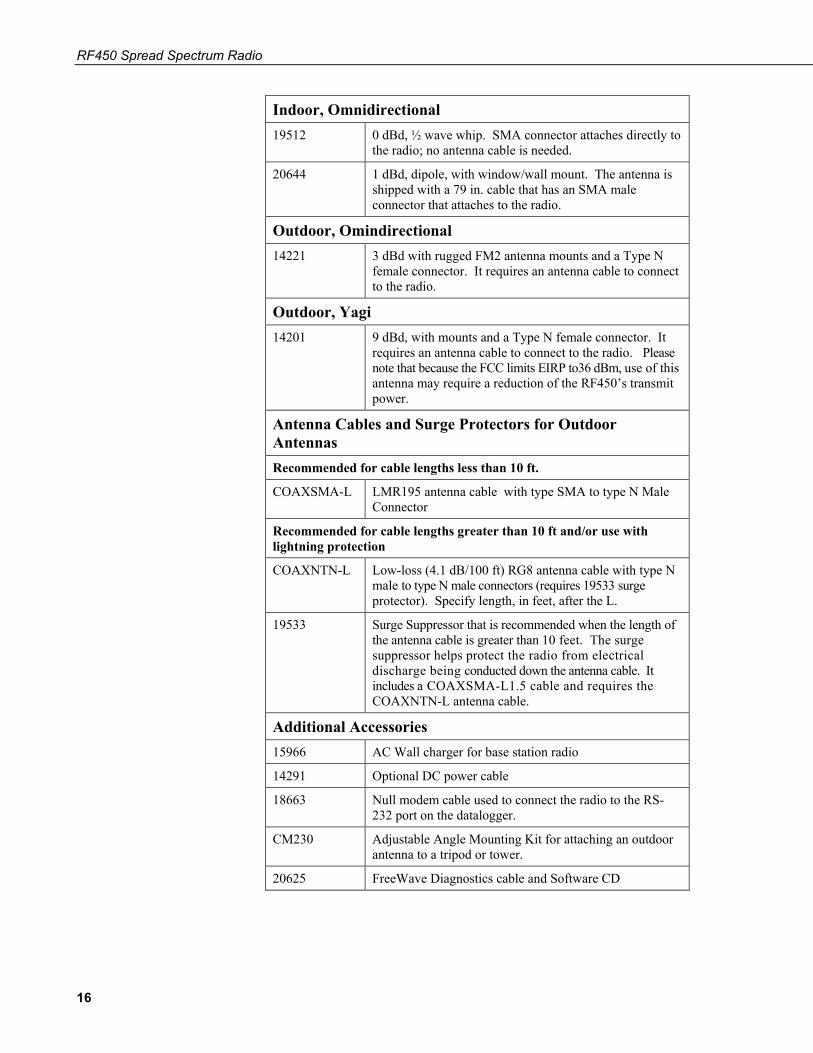
Indoor, Omnidirectional 19512 0 dBd, ½ wave whip. SMA connector attaches directly to
the radio; no antenna cable is needed.
20644 1 dBd, dipole, with window/wall mount. The antenna is shipped with a 79 in. cable that has an SMA male connector that attaches to the radio.
Outdoor, Omindirectional 14221 3 dBd with rugged FM2 antenna mounts and a Type N
female connector. It requires an antenna cable to connect to the radio.
Outdoor, Yagi 14201 9 dBd, with mounts and a Type N female connector. It
requires an antenna cable to connect to the radio. Please note that because the FCC limits EIRP to36 dBm, use of this antenna may require a reduction of the RF450’s transmit power.
Antenna Cables and Surge Protectors for Outdoor Antennas Recommended for cable lengths less than 10 ft. COAXSMA-L LMR195 antenna cable with type SMA to type N Male
Connector
Recommended for cable lengths greater than 10 ft and/or use with lightning protection
COAXNTN-L Low-loss (4.1 dB/100 ft) RG8 antenna cable with type N male to type N male connectors (requires 19533 surge protector). Specify length, in feet, after the L.
19533 Surge Suppressor that is recommended when the length of the antenna cable is greater than 10 feet. The surge suppressor helps protect the radio from electrical discharge being conducted down the antenna cable. It includes a COAXSMA-L1.5 cable and requires the COAXNTN-L antenna cable.
Additional Accessories 15966 AC Wall charger for base station radio
14291 Optional DC power cable
18663 Null modem cable used to connect the radio to the RS-232 port on the datalogger.
CM230 Adjustable Angle Mounting Kit for attaching an outdoor antenna to a tripod or tower.
20625 FreeWave Diagnostics cable and Software CD
16
RF450 Spread Spectrum Radio
FCC OET Bulletin No. 63 (October 1993)
Changing the antenna on a transmitter can significantly increase, or decrease, the strength of the signal that is ultimately transmitted. Except for cable locating equipment, the standards in Part 15 are not based solely on output power but also take into account the antenna characteristics. Thus, a low power transmitter that complies with the technical standards in Part 15 with a particular antenna attached can exceed the Part 15 standards if a different antenna is attached. Should this happen it could pose a serious interference problem to authorized radio communications such as emergency, broadcast, and air-traffic control communications.
In order to comply with the FCC RF exposure requirements, the RF450 series may be used only with approved antennas that have been tested with this radio and a minimum separation distance of 20 cm must be maintained from the antenna to any nearby persons.
5.2 Antenna Cables and Surge Protection 5.2.1 Antenna Cables
The 14201, 14221, 19512, and 20XXX antennas require an antenna cable; either (1) the COAXSMA-L cable or (2) the COAXNTN-L cable with surge protector. Indoor omnidirectional antennas are either supplied with an appropriate cable or connect directly to the radio.
5.2.2 Electrostatic Issues Many RF450 series installations are out of doors and therefore susceptible to lightning damage, especially via the antenna system. Also, depending on climate and location, electro-statically charged wind can damage sensitive electronics if sufficient electric charge is allowed to accumulate on the antenna and cable. To protect against this, Campbell Scientific offers the Item # 19533 Antenna Surge Protection Kit.
Antenna surge protection is recommended in the following applications:
• When the antenna cable length exceeds 10 feet
• When use of COAXSMA cable would result in too much signal loss
• When the radio will be used in an environment susceptible to lightning or electro-static buildup
5.2.3 Antenna Surge Protector Kit The Surge Protector Kit includes the following:
• Polyphaser protector
• COAXSMA-L cable with 1.5 ft length (its type N male connector fastens to the polyphaser’s equipment connector; its SMA connector fastens to the radio’s antenna connector)
• Screw (pn 505) and grommet (pn 6044) to secure the polyphaser protector to the backplate of an enclosure
CAUTION
17
RF450 Spread Spectrum Radio
• 1.5 ft, 10 AWG ground wire (insert one end of the wire between the #505 screw and the polyphaser, then secure the other end to a ground lug)
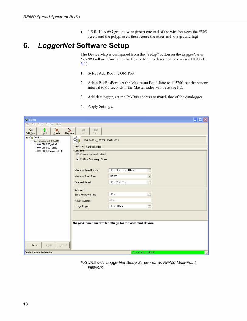
6. LoggerNet Software Setup The Device Map is configured from the “Setup” button on the LoggerNet or PC400 toolbar. Configure the Device Map as described below (see FIGURE 6-1).
1. Select Add Root | COM Port.
2. Add a PakBusPort, set the Maximum Baud Rate to 115200, set the beacon interval to 60 seconds if the Master radio will be at the PC.
3. Add datalogger, set the PakBus address to match that of the datalogger.
4. Apply Settings.
FIGURE 6-1. LoggerNet Setup Screen for an RF450 Multi-Point Network
18
RF450 Spread Spectrum Radio
7. RF450s with RF401 or CR206(X) in the Same Network
Using RF450s in the same network as Campbell Scientific's RF401 radios or CR206(X) dataloggers is not recommended. RF450s will not communicate directly with RF401s and CR206(X)s. The RF450s will interfere with the RF401s’ and CR206(X)s’ transmissions. If RF450s and RF401/CR206(X)s must be in the same network, there are some things you can do to get better performance out of the RF401 portion of your network:
1. Use Yagi antennas and separate them.
2. Disable Frequency Zones 4 through 11 on the RF450. This is done through the Settings Editor Tab of DevConfig.
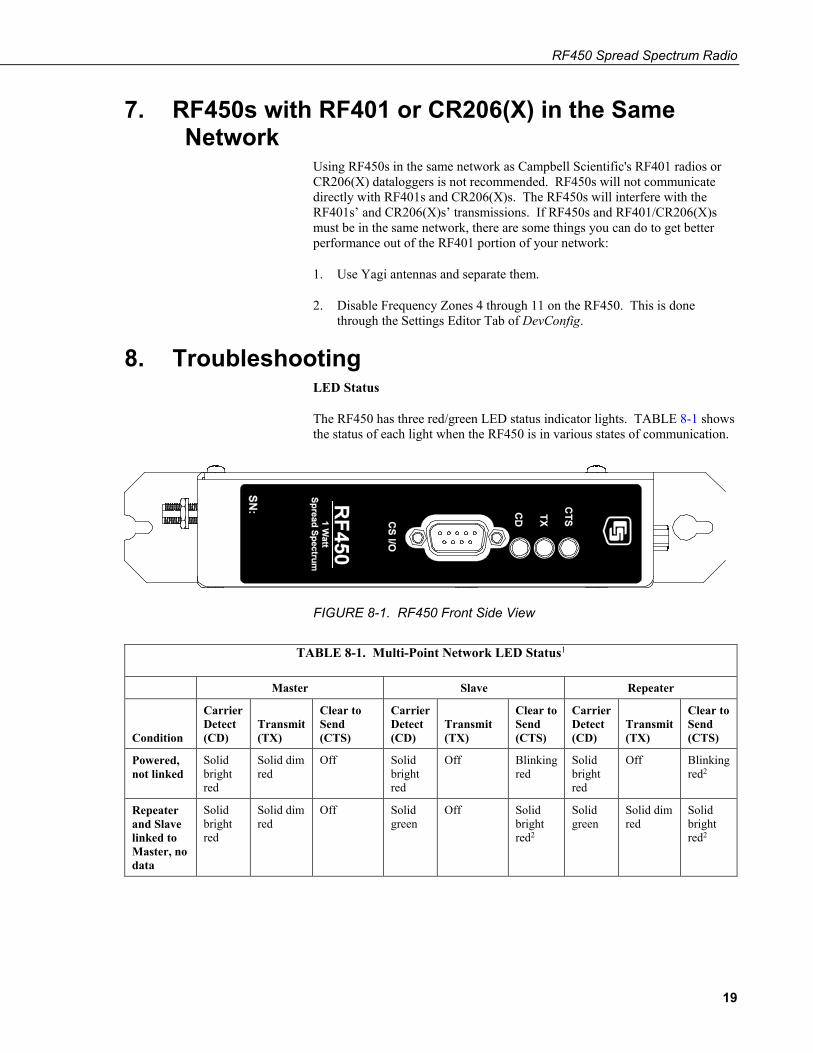
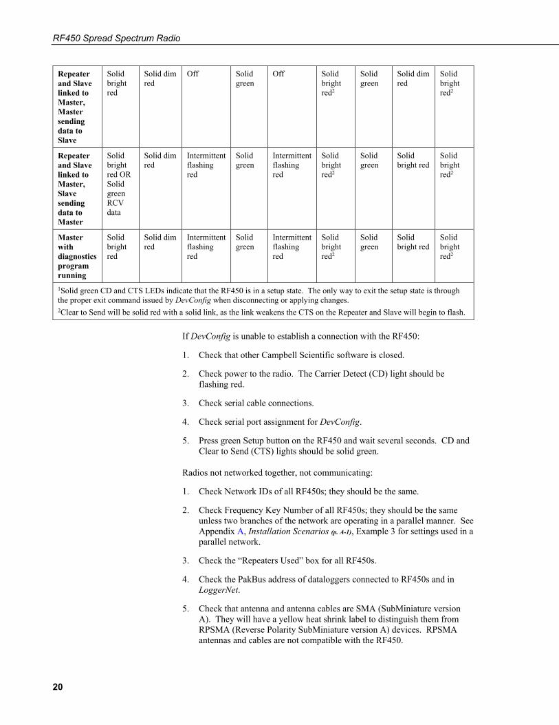
8. Troubleshooting LED Status
The RF450 has three red/green LED status indicator lights. TABLE 8-1 shows the status of each light when the RF450 is in various states of communication.
FIGURE 8-1. RF450 Front Side View
TABLE 8-1. Multi-Point Network LED Status1
Master Slave Repeater
Condition
Carrier Detect (CD)
Transmit (TX)
Clear to Send (CTS)
Carrier Detect (CD)
Transmit (TX)
Clear to Send (CTS)
Carrier Detect (CD)
Transmit (TX)
Clear to Send (CTS)
Powered, not linked
Solid bright red
Solid dim red
Off Solid bright red
Off Blinking red
Solid bright red
Off Blinking red2
Repeater and Slave linked to Master, no data
Solid bright red
Solid dim red
Off Solid green
Off Solid bright red2
Solid green
Solid dim red
Solid bright red2
19
RF450 Spread Spectrum Radio
Repeater and Slave linked to Master, Master sending data to Slave
Solid bright red
Solid dim red
Off Solid green
Off Solid bright red2
Solid green
Solid dim red
Solid bright red2
Repeater and Slave linked to Master, Slave sending data to Master
Solid bright red OR Solid green RCV data
Solid dim red
Intermittent flashing red
Solid green
Intermittent flashing red
Solid bright red2
Solid green
Solid bright red
Solid bright red2
Master with diagnostics program running
Solid bright red
Solid dim red
Intermittent flashing red
Solid green
Intermittent flashing red
Solid bright red2
Solid green
Solid bright red
Solid bright red2
1Solid green CD and CTS LEDs indicate that the RF450 is in a setup state. The only way to exit the setup state is through the proper exit command issued by DevConfig when disconnecting or applying changes. 2Clear to Send will be solid red with a solid link, as the link weakens the CTS on the Repeater and Slave will begin to flash.
If DevConfig is unable to establish a connection with the RF450:
1. Check that other Campbell Scientific software is closed.
2. Check power to the radio. The Carrier Detect (CD) light should be flashing red.
3. Check serial cable connections.
4. Check serial port assignment for DevConfig.
5. Press green Setup button on the RF450 and wait several seconds. CD and Clear to Send (CTS) lights should be solid green.
Radios not networked together, not communicating:
1. Check Network IDs of all RF450s; they should be the same.
2. Check Frequency Key Number of all RF450s; they should be the same unless two branches of the network are operating in a parallel manner. See Appendix A, Installation Scenarios (p. A-1), Example 3 for settings used in a parallel network.
3. Check the “Repeaters Used” box for all RF450s.
4. Check the PakBus address of dataloggers connected to RF450s and in LoggerNet.
5. Check that antenna and antenna cables are SMA (SubMiniature version A). They will have a yellow heat shrink label to distinguish them from RPSMA (Reverse Polarity SubMiniature version A) devices. RPSMA antennas and cables are not compatible with the RF450.
20
RF450 Spread Spectrum Radio
LEDs flash when LoggerNet command transmitted but no response from datalogger:
1. Check SC12 cable on the datalogger's CS I/O port.
2. Check SDC address in RF450.
3. Check SDC address in datalogger.
4. Check the baud rate of LoggerNet; it should match the baud rate of the RF450 attached to it.
Using the diagnostics port.
A special FreeWave Diagnostics cable and software (CSI part number 20625) can be useful in troubleshooting radio problems. Contact FreeWave Inc. for more information on using the Diagnostics cable.
21

RF450 Spread Spectrum Radio
22
Appendix A. Installation Scenarios A.1 Example 1: PC-to-RF Network
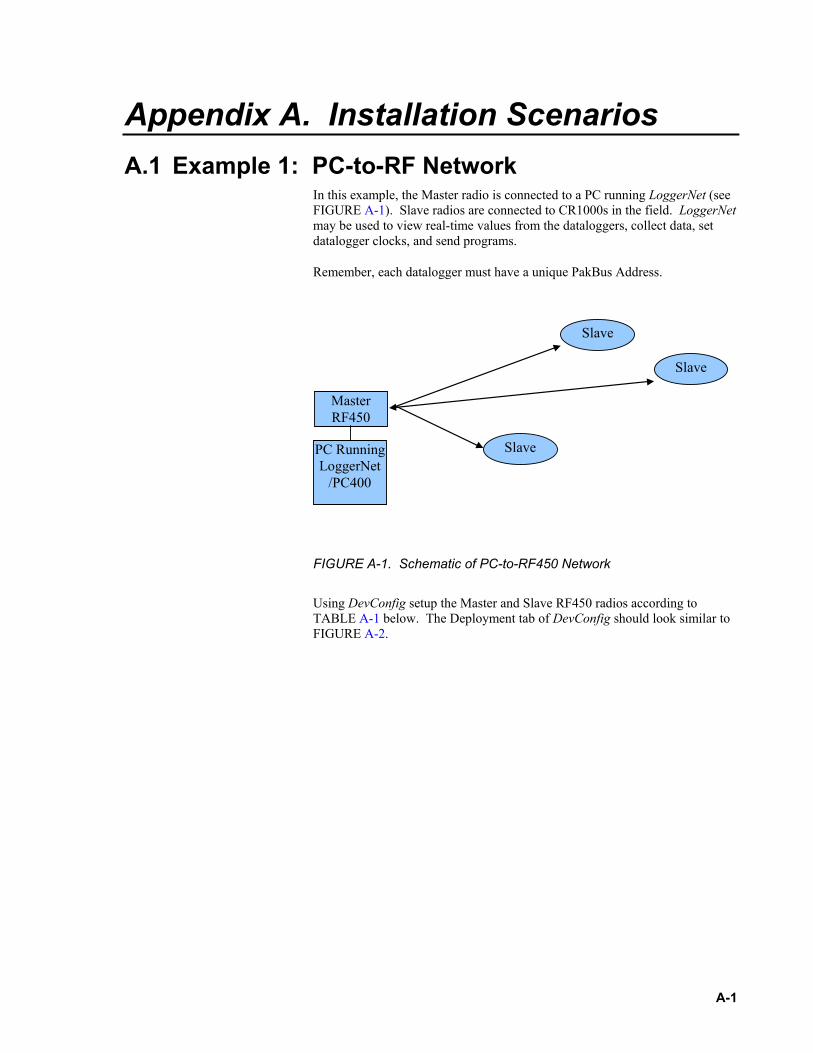
In this example, the Master radio is connected to a PC running LoggerNet (see FIGURE A-1). Slave radios are connected to CR1000s in the field. LoggerNet may be used to view real-time values from the dataloggers, collect data, set datalogger clocks, and send programs.
Remember, each datalogger must have a unique PakBus Address.
Master RF450
Slave
Slave
Slave PC Running LoggerNet
/PC400
FIGURE A-1. Schematic of PC-to-RF450 Network
Using DevConfig setup the Master and Slave RF450 radios according to TABLE A-1 below. The Deployment tab of DevConfig should look similar to FIGURE A-2.
A-1
Appendix A. Installation Scenarios
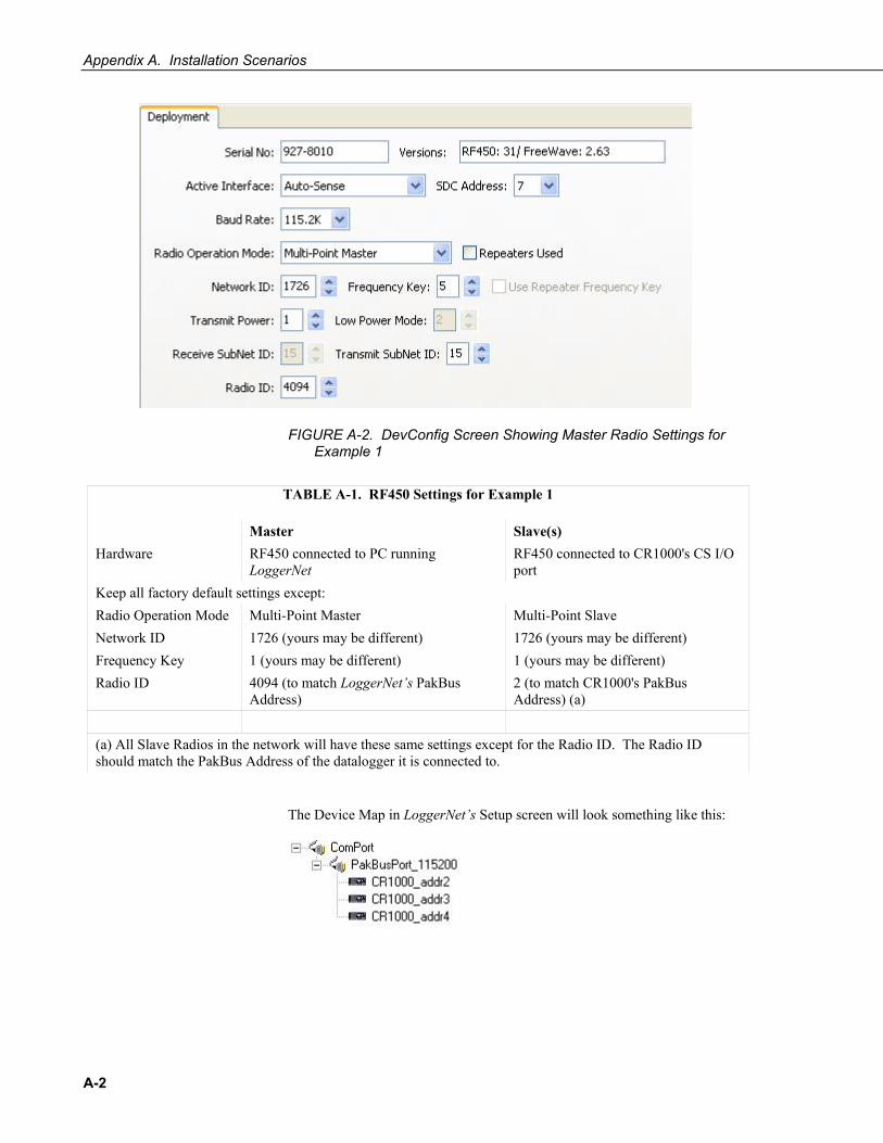
FIGURE A-2. DevConfig Screen Showing Master Radio Settings for Example 1
TABLE A-1. RF450 Settings for Example 1
Master Slave(s) Hardware RF450 connected to PC running
LoggerNet RF450 connected to CR1000's CS I/O port
Keep all factory default settings except: Radio Operation Mode Multi-Point Master Multi-Point Slave Network ID 1726 (yours may be different) 1726 (yours may be different) Frequency Key 1 (yours may be different) 1 (yours may be different) Radio ID 4094 (to match LoggerNet’s PakBus
Address) 2 (to match CR1000's PakBus Address) (a)
(a) All Slave Radios in the network will have these same settings except for the Radio ID. The Radio ID should match the PakBus Address of the datalogger it is connected to.
The Device Map in LoggerNet’s Setup screen will look something like this:
A-2
Appendix A. Installation Scenarios
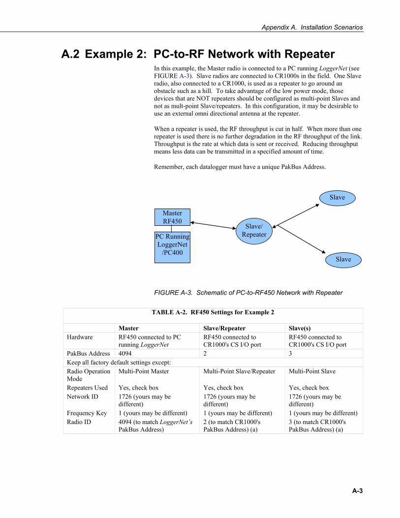
A.2 Example 2: PC-to-RF Network with Repeater In this example, the Master radio is connected to a PC running LoggerNet (see FIGURE A-3). Slave radios are connected to CR1000s in the field. One Slave radio, also connected to a CR1000, is used as a repeater to go around an obstacle such as a hill. To take advantage of the low power mode, those devices that are NOT repeaters should be configured as multi-point Slaves and not as mult-point Slave/repeaters. In this configuration, it may be desirable to use an external omni directional antenna at the repeater.
When a repeater is used, the RF throughput is cut in half. When more than one repeater is used there is no further degradation in the RF throughput of the link. Throughput is the rate at which data is sent or received. Reducing throughput means less data can be transmitted in a specified amount of time.
Remember, each datalogger must have a unique PakBus Address.
Master RF450
Slave
Slave
Slave/ Repeater PC Running
LoggerNet /PC400
FIGURE A-3. Schematic of PC-to-RF450 Network with Repeater
TABLE A-2. RF450 Settings for Example 2
Master Slave/Repeater Slave(s) Hardware RF450 connected to PC
running LoggerNet RF450 connected to CR1000's CS I/O port
RF450 connected to CR1000's CS I/O port
PakBus Address 4094 2 3 Keep all factory default settings except: Radio Operation Mode
Multi-Point Master Multi-Point Slave/Repeater Multi-Point Slave
Repeaters Used Yes, check box Yes, check box Yes, check box Network ID 1726 (yours may be
different) 1726 (yours may be different)
1726 (yours may be different)
Frequency Key 1 (yours may be different) 1 (yours may be different) 1 (yours may be different) Radio ID 4094 (to match LoggerNet’s
PakBus Address) 2 (to match CR1000's PakBus Address) (a)
3 (to match CR1000's PakBus Address) (a)
A-3
Appendix A. Installation Scenarios
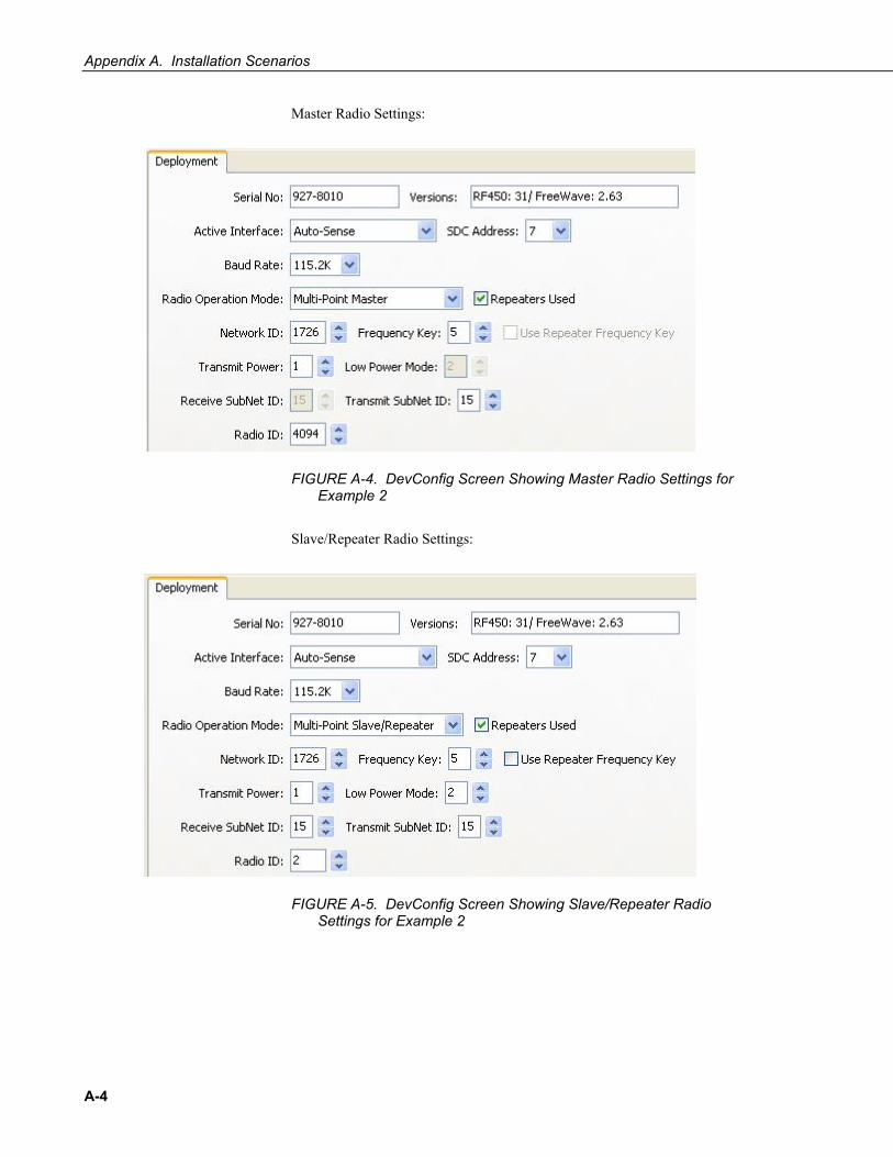
Master Radio Settings:
FIGURE A-4. DevConfig Screen Showing Master Radio Settings for Example 2
Slave/Repeater Radio Settings:
FIGURE A-5. DevConfig Screen Showing Slave/Repeater Radio Settings for Example 2
A-4
Appendix A. Installation Scenarios
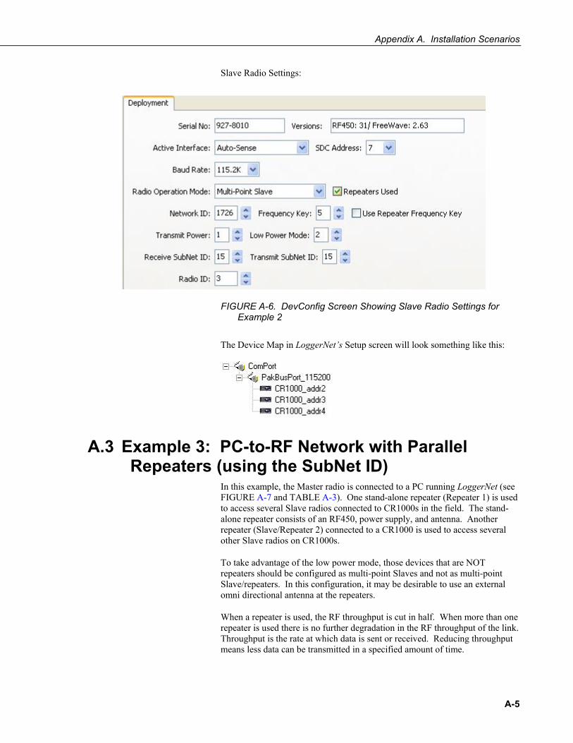
Slave Radio Settings:
FIGURE A-6. DevConfig Screen Showing Slave Radio Settings for Example 2
The Device Map in LoggerNet’s Setup screen will look something like this:
A.3 Example 3: PC-to-RF Network with Parallel Repeaters (using the SubNet ID)
In this example, the Master radio is connected to a PC running LoggerNet (see FIGURE A-7 and TABLE A-3). One stand-alone repeater (Repeater 1) is used to access several Slave radios connected to CR1000s in the field. The stand-alone repeater consists of an RF450, power supply, and antenna. Another repeater (Slave/Repeater 2) connected to a CR1000 is used to access several other Slave radios on CR1000s.
To take advantage of the low power mode, those devices that are NOT repeaters should be configured as multi-point Slaves and not as multi-point Slave/repeaters. In this configuration, it may be desirable to use an external omni directional antenna at the repeaters.
When a repeater is used, the RF throughput is cut in half. When more than one repeater is used there is no further degradation in the RF throughput of the link. Throughput is the rate at which data is sent or received. Reducing throughput means less data can be transmitted in a specified amount of time.
A-5
Appendix A. Installation Scenarios
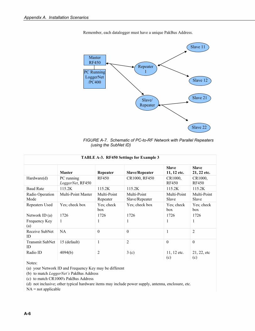
Remember, each datalogger must have a unique PakBus Address.
Master RF450
Slave 12
Slave 11
PC Running LoggerNet
/PC400
Repeater 1
Slave/ Repeater
Slave 22
Slave 21
FIGURE A-7. Schematic of PC-to-RF Network with Parallel Repeaters (using the SubNet ID)
TABLE A-3. RF450 Settings for Example 3
Master
Repeater
Slave/Repeater
Slave 11, 12 etc.
Slave 21, 22 etc.
Hardware(d) PC running LoggerNet, RF450
RF450 CR1000, RF450 CR1000, RF450
CR1000, RF450
Baud Rate 115.2K 115.2K 115.2K 115.2K 115.2K Radio Operation Mode
Multi-Point Master Multi-Point Repeater
Multi-Point Slave/Repeater
Multi-Point Slave
Multi-Point Slave
Repeaters Used Yes; check box Yes; check box
Yes; check box Yes; check box
Yes; check box
Network ID (a) 1726 1726 1726 1726 1726 Frequency Key (a)
1 1 1 1 1
Receive SubNet ID
NA 0 0 1 2
Transmit SubNet ID
15 (default) 1 2 0 0
Radio ID 4094(b) 2 3 (c) 11, 12 etc. (c)
21, 22, etc (c)
Notes: (a) your Network ID and Frequency Key may be different (b) to match LoggerNet’s PakBus Address (c) to match CR1000's PakBus Address (d) not inclusive; other typical hardware items may include power supply, antenna, enclosure, etc. NA = not applicable
A-6
Appendix A. Installation Scenarios
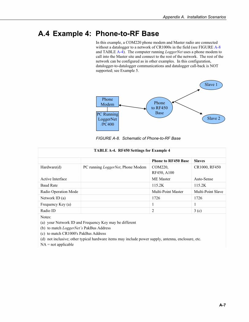
A.4 Example 4: Phone-to-RF Base In this example, a COM220 phone modem and Master radio are connected without a datalogger to a network of CR1000s in the field (see FIGURE A-8 and TABLE A-4). The computer running LoggerNet uses a phone modem to call into the Master site and connect to the rest of the network. The rest of the network can be configured as in other examples. In this configuration, datalogger-to-datalogger communications and datalogger call-back is NOT supported; see Example 5.
Phone Modem
Slave 2
Slave 1
PC Running LoggerNet
/PC400
Phone to RF450
Base
FIGURE A-8. Schematic of Phone-to-RF Base
TABLE A-4. RF450 Settings for Example 4
Phone to RF450 Base Slaves Hardware(d) PC running LoggerNet, Phone Modem COM220,
RF450, A100 CR1000, RF450
Active Interface ME Master Auto-Sense Baud Rate 115.2K 115.2K Radio Operation Mode Multi-Point Master Multi-Point Slave Network ID (a) 1726 1726 Frequency Key (a) 1 1 Radio ID 2 3 (c) Notes: (a) your Network ID and Frequency Key may be different (b) to match LoggerNet’s PakBus Address (c) to match CR1000's PakBus Address (d) not inclusive; other typical hardware items may include power supply, antenna, enclosure, etc. NA = not applicable
A-7
Appendix A. Installation Scenarios
A.5 Example 5: Call-back Call-back is the ability of a remote site to initiate a call to LoggerNet and have LoggerNet call back to collect data. Call-back is supported in networks consisting of RF450s as the single communications device as in Examples 1, 2, and 3. Example configurations where call-back is supported:
LN-RF450 Master ~~~~~RF450 Slave -DL
LN-RF450 Master ~~~~~~RF450 Slave/Repeater-DL~~~~~~RF450 Slave-DL
LN-RF450 Master ~~~~~~~~RF450 Repeater ~~~~~~~~RF450 Slave -DL
LN-Phone Modem -----COM220-DL-RF450 Master ~~~~~~RF450 Slave -DL
NOTE: LN=LoggerNet; DL=Datalogger
In a mixed-communication devices network, e.g. phone to RF450, the base site makes the transition between communication types. Call-back is NOT supported when the base RF450's Active Interface is configured as Modem Enable (ME) Master. The RF450's Active Interface is configured as ME Master when the CS I/O port is used for direct connection to a ME device (COM200, COM210, COM220, MD485, etc). The connection is done by using an A100. Example configurations where call-back is NOT supported:
LN-Phone Modem -----COM220-CSI null modem-RF450 Master~~~~~RF450 Slave -DL(1)
LN--Ethernet--RavenXT-rs232nullmodem-RF450 Master~~RF450 Slave -DL
NOTE: LN=LoggerNet; DL=Datalogger
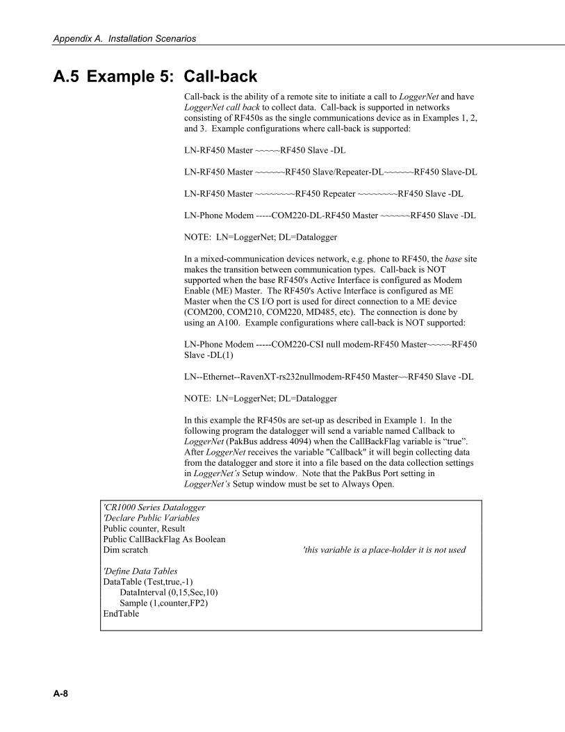
In this example the RF450s are set-up as described in Example 1. In the following program the datalogger will send a variable named Callback to LoggerNet (PakBus address 4094) when the CallBackFlag variable is “true”. After LoggerNet receives the variable "Callback" it will begin collecting data from the datalogger and store it into a file based on the data collection settings in LoggerNet’s Setup window. Note that the PakBus Port setting in LoggerNet’s Setup window must be set to Always Open.
'CR1000 Series Datalogger 'Declare Public Variables Public counter, Result Public CallBackFlag As Boolean Dim scratch 'this variable is a place-holder it is not used 'Define Data Tables DataTable (Test,true,-1) DataInterval (0,15,Sec,10) Sample (1,counter,FP2) EndTable
A-8
Appendix A. Installation Scenarios
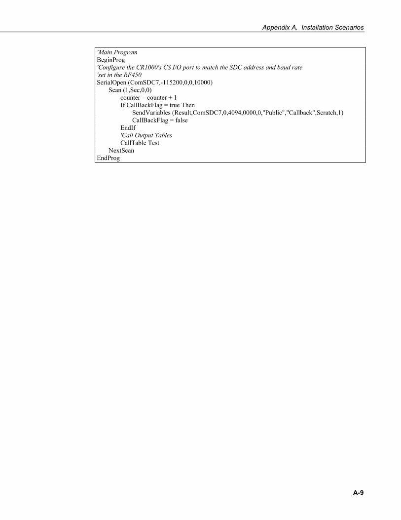
'Main Program BeginProg 'Configure the CR1000's CS I/O port to match the SDC address and baud rate 'set in the RF450 SerialOpen (ComSDC7,-115200,0,0,10000) Scan (1,Sec,0,0) counter = counter + 1 If CallBackFlag = true Then SendVariables (Result,ComSDC7,0,4094,0000,0,"Public","Callback",Scratch,1) CallBackFlag = false EndIf 'Call Output Tables CallTable Test NextScan EndProg
A-9

Appendix A. Installation Scenarios
A-10
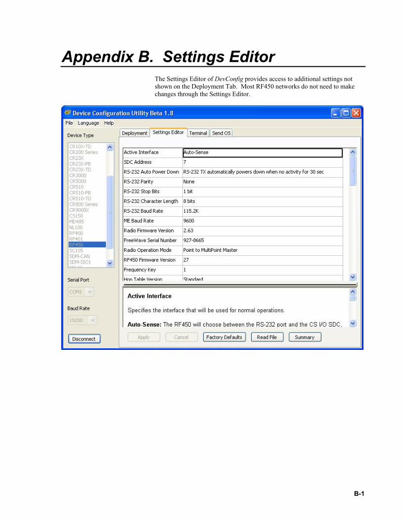
Appendix B. Settings Editor The Settings Editor of DevConfig provides access to additional settings not shown on the Deployment Tab. Most RF450 networks do not need to make changes through the Settings Editor.
B-1
Appendix B. Settings Editor
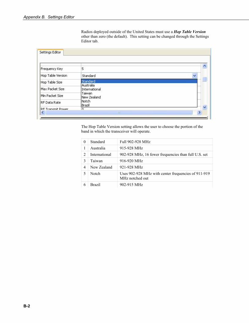
Radios deployed outside of the United States must use a Hop Table Version other than zero (the default). This setting can be changed through the Settings Editor tab.
The Hop Table Version setting allows the user to choose the portion of the band in which the transceiver will operate.
0 Standard Full 902-928 MHz 1 Australia 915-928 MHz 2 International 902-928 MHz, 16 fewer frequencies than full U.S. set 3 Taiwan 916-920 MHz 4 New Zealand 921-928 MHz 5 Notch Uses 902-928 MHz with center frequencies of 911-919
MHz notched out 6 Brazil 902-915 MHz
B-2

Campbell Scientific Companies
Campbell Scientific, Inc. (CSI) 815 West 1800 North Logan, Utah 84321 UNITED STATES
www.campbellsci.com • [email protected]
Campbell Scientific Africa Pty. Ltd. (CSAf) PO Box 2450
Somerset West 7129 SOUTH AFRICA
www.csafrica.co.za • [email protected]
Campbell Scientific Australia Pty. Ltd. (CSA) PO Box 8108
Garbutt Post Shop QLD 4814 AUSTRALIA
www.campbellsci.com.au • [email protected]
Campbell Scientific (Beijing) Co., Ltd. 8B16, Floor 8 Tower B, Hanwei Plaza
7 Guanghua Road Chaoyang, Beijing 100004
P.R. CHINA www.campbellsci.com • [email protected]
Campbell Scientific do Brasil Ltda. (CSB) Rua Apinagés, nbr. 2018 ─ Perdizes CEP: 01258-00 ─ São Paulo ─ SP
BRASIL www.campbellsci.com.br • [email protected]
Campbell Scientific Canada Corp. (CSC) 14532 – 131 Avenue NW Edmonton AB T5L 4X4
CANADA www.campbellsci.ca • [email protected]
Campbell Scientific Centro Caribe S.A. (CSCC) 300 N Cementerio, Edificio Breller
Santo Domingo, Heredia 40305 COSTA RICA
www.campbellsci.cc • [email protected]
Campbell Scientific Ltd. (CSL) Campbell Park
80 Hathern Road Shepshed, Loughborough LE12 9GX
UNITED KINGDOM www.campbellsci.co.uk • [email protected]
Campbell Scientific Ltd. (CSL France) 3 Avenue de la Division Leclerc
92160 ANTONY FRANCE
www.campbellsci.fr • [email protected]
Campbell Scientific Ltd. (CSL Germany) Fahrenheitstraße 13
28359 Bremen GERMANY
www.campbellsci.de • [email protected]
Campbell Scientific Spain, S. L. (CSL Spain) Avda. Pompeu Fabra 7-9, local 1
08024 Barcelona SPAIN
www.campbellsci.es • [email protected]
Please visit www.campbellsci.com to obtain contact information for your local US or international representative.