Embed Size (px)
Citation preview
Status: OPEN
Priority: Normal
Due Date: Mar 20, 2017
Question Type: Stru
Cost Impact: TBD
Schedule Impact: none
Logged in as:Project #1603
RFI #91: Generator Concrete slab as specified bystructural engineer of record.
Original Question:
Submitted by: David Edgerton
We need to know the size of Generator pad, how thick, and if rebarrequired?
On Sheet C2.1 note 10 say's "Generator, see Electrical plans". When welook at electrical plans, sheet E1.1 refers to detail 1/E7.1 & 1/E5.1.Detail 1/E5.1 does not any information for Generator pad. Detail1/E7.1 does not have any information for Generator pad. In Generator submittals, (pages 39-43) it refers to aconcrete slab as specified by structural engineer of record.
Please provide detail for Generator Pad.
Replies
No replies yet.
Subcontractor is advised that it SHALL strictly satisfy any and all mandatory notice, protest, and claims procedures for
all claims, including without limitation claims for additional compensation, time extensions, and/or changed
conditions, that exist within the terms and conditions of Owner-General Contract (including those found within
General and Supplementary Conditions), where applicable, and the terms and conditions of the Subcontract (including
those found within General and Supplementary Conditions).
FAILURE TO STRICTLY SATISFY THOSE PROCEDURAL OBLIGATIONS CONSTITUTES AN IRREVOCABLE
WAIVER OF ANY SUCH CLAIM.
RFI 132 Corp Inc_FS1_RFI 91
APPLIES TO: Fire Station 1 Fire Station 2
See detail 10/A8.8: 8" concrete pad w/#4 rebar @ 18" O.C. each way. MHB3/22/2017
X
X
Rev. 04.18.14
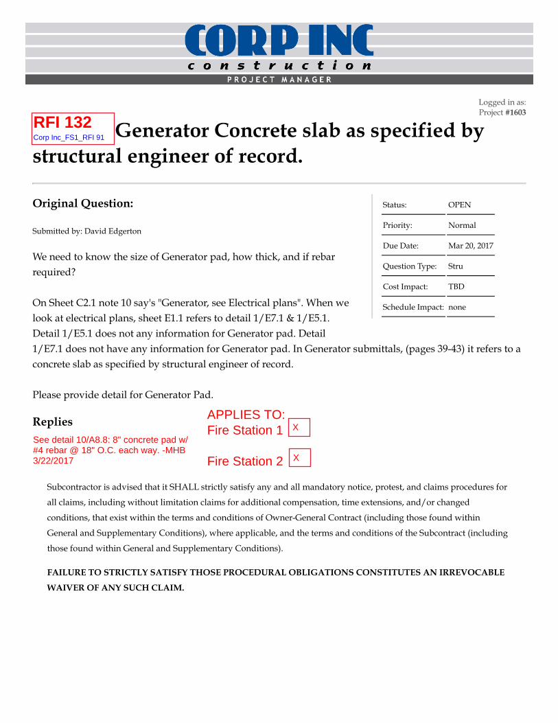
Letter of TransmittalTo:
Re:
From:Customer PO#:
Attn:[email protected]
attached
The following items:
X
Copies: Number: Description:PDF
These are transmitted as checked below:
XX
Resubmit Copies for approvalSubmit Copies for distribution
X Return PDF Copy of approved submittal
Remarks:
Sincerely,
Anchorage, AK Coburg, OR Seattle, WA
Missoula, MT Medford,OR Yakima, WA
Pendleton, OR
We are sending you Under separate cover via: Email
JH Kelly LLC821 3rd AveLongview, WA 98632
November 18, 2016
Vancouver Fire Station #1
Cummins, Inc. (Portland)4711 N Basin AvePortland, OR 97217Ph: (503) 289-0900 Fax: (503) 286-5938
Cummins Project #: 4627716363.0005-Rev01
Bob Breien
Catalog Outline Drawings SubmittalO & M Manual Re-Submittals Other
Approved as Submitted
Specifications Record Drawings
Vancouver Fire Station #1
For approval Approved as notedFor your use Returned for correctionsAs requestedFor review & comment
Equipment production is on "HOLD" pending drawing approval. After one copy is marked "APPROVED" and returned, this equipment will be released for production.
Dennis Tarr (503) 341-8597
Spokane, WA
Chehalis, WA
Portland, OR
1
Submittal
Cummins Pacific Region
Washington, Oregon, Alaska, California, Hawaii
Powerful Solutions. Dependable Support. Every Time
Vancouver Fire Station #1
November 10, 2016
SUBMITTAL
TO
JH Kelly LLC
FOR
Vancouver Fire Station #1
CUMMINS GENERATOR SET Model: C100 D6C
Approximate Generator set only w/enclosure Weight: 2,700 Lbs.Approximate base tank only weight 3,600 Lbs.
CUMMINS AUTOMATIC TRANSFER SWITCH – POWERCOMMAND Model: OTEC 150, OTEC 225
Approximate Transfer Switch Package Weight: 165 Lbs.
Project Number: 46277
Contact: Dennis Tarr Office: 503-289-0900 ex 1405
Fax: 503-341-8597 Email: [email protected]
salesandservice.cummins.com

Table of Contents Material Summary ................................................................................................................................................... Exclusions ..................................................................................................................................................................
Pre Start-Up Checklist ............................................................................................................................................. Warranty-Generator ..........................................................................................................................................................
Warranty-ATS ..........................................................................................................................................................
Generator
Specification Sheet ..................................................................................................................................................... Generator Data Sheet ..................................................................................................................................................
Power Command Digital Generator Set Control ........................................................................................................ Exhaust Emission Data Sheet ..............................................................................................................................................
Exhaust Compliance Data Sheet ..........................................................................................................................................
Cooling Data ........................................................................................................................................................................
Sound Data ..........................................................................................................................................................................
Prototype ..............................................................................................................................................................................
Alternator Data Sheet ...........................................................................................................................................................
Seismic Certification ..................................................................................................................................................
Installation Guidelines ................................................................................................................................................ Enclosure Specifications .....................................................................................................................................................
Generator Outline Drawing ..................................................................................................................................................
Enclosure Outline Drawing .................................................................................................................................................
Fuel Tank Outline Drawing and Accessories .......................................................................................................................
Circuit Breaker Info and location drawing .........................................................................................................................................
Interconnect Diagram ...........................................................................................................................................................
Transfer Switch
Specification Sheet ..................................................................................................................................................... Seismic Certification ..................................................................................................................................................
Cabinet Outline Drawing ............................................................................................................................................ Wiring Diagram ..........................................................................................................................................................
Accessories
Battery Charger Data ..................................................................................................................................................

Quotation
Cummins, Inc 4711 N Basin Ave Portland, Oregon OR 97217 United States Direct: 503-972-6615 November 18, 2016
Project Name: City of Vancouver Station 1 and 2 (Note: 100 DSGAA being replaced by this new model) SAME PRICE
Quotation: 2142000000318578
Thank you for your inquiry. We are pleased to quote as follows:
USD
Item Description Qty
Diesel Genset: 60Hz-100kW Install-US-Stat U.S. EPA, Stationary Emergency Application 1 C100 D6C Genset-Diesel, 60Hz, 100kW-Standby Rating 1 A331-2 Duty Rating-Standby Power 1 L090-2 Listing-UL 2200 1 L193-2 NFPA 110 Type 10 Level 1 Capable 1 L228-2 Certification-Seismic, IBC2000, IBC2003, IBC2006, IBC2009, IBC2012 1 L169-2 Emissions Certification, EPA, Tier 3, NSPS CI Stationary Emergency 1 F216-2 Enclosure-Aluminum,Weather Protective,w/Exh System rated 81.5 dba @ 23’ 1 R098-2 Voltage-120/208,3 Phase,Wye,4 Wire 1 B946-2 Alternator-60Hz,12L,208/120V,120C,40C amb 1 H703-2 Generator Set Control-PowerCommand 2.3 1 B184-2 Exciter/Regulator-Pmg, 3 Phase Sensor 1 A366-2 Engine Governor-Electronic, Isochronous Only 1 H536-2 Display Language-English 1 H012-2 Gauge-Oil Pressure 1 H720-2 AmpSentryTM Protective Relay 1 K796-2 Stop Switch-Emergency 1 H609-2 Control Mounting-Left Facing 1 A292-2 Heater-Alternator, 120 Volt AC 1 KV04-2 Load Connections-Dual 1 KV35-2 CB,Loc A,50A,3P,600VAC,80%,UL 1 KX28-2 CB,Loc B,70A-250A,3P,LSI,600VAC,100%,UL 1 P176-2 Enclosure Color-Green,Aluminum Enclosure 1 F252-2 Enclosure - Wind Load 180MPH, ASCE7-10 1
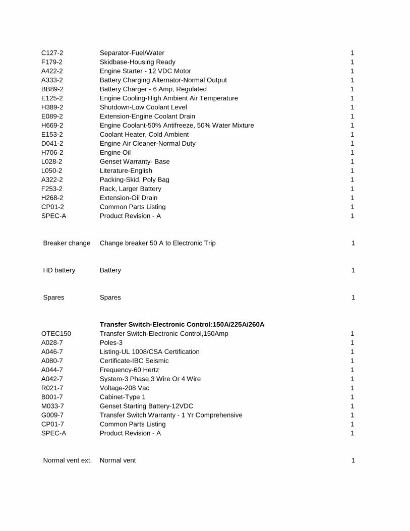
C127-2 Separator-Fuel/Water 1 F179-2 Skidbase-Housing Ready 1 A422-2 Engine Starter - 12 VDC Motor 1 A333-2 Battery Charging Alternator-Normal Output 1 BB89-2 Battery Charger - 6 Amp, Regulated 1 E125-2 Engine Cooling-High Ambient Air Temperature 1 H389-2 Shutdown-Low Coolant Level 1 E089-2 Extension-Engine Coolant Drain 1 H669-2 Engine Coolant-50% Antifreeze, 50% Water Mixture 1 E153-2 Coolant Heater, Cold Ambient 1 D041-2 Engine Air Cleaner-Normal Duty 1 H706-2 Engine Oil 1 L028-2 Genset Warranty- Base 1 L050-2 Literature-English 1 A322-2 Packing-Skid, Poly Bag 1 F253-2 Rack, Larger Battery 1 H268-2 Extension-Oil Drain 1 CP01-2 Common Parts Listing 1 SPEC-A Product Revision - A 1
Breaker change Change breaker 50 A to Electronic Trip 1
HD battery Battery 1
Spares Spares 1
Transfer Switch-Electronic Control:150A/225A/260A OTEC150 Transfer Switch-Electronic Control,150Amp 1 A028-7 Poles-3 1 A046-7 Listing-UL 1008/CSA Certification 1 A080-7 Certificate-IBC Seismic 1 A044-7 Frequency-60 Hertz 1 A042-7 System-3 Phase,3 Wire Or 4 Wire 1 R021-7 Voltage-208 Vac 1 B001-7 Cabinet-Type 1 1 M033-7 Genset Starting Battery-12VDC 1 G009-7 Transfer Switch Warranty - 1 Yr Comprehensive 1 CP01-7 Common Parts Listing 1 SPEC-A Product Revision - A 1
Normal vent ext. Normal vent 1

Commercial Accessories 0300-4521 Rupture Basin Switch Kit (C158) 1
Transfer Switch-Electronic Control:150A/225A/260A OTEC225 Transfer Switch-Electronic Control,225Amp 1 A028-7 Poles-3 1 A046-7 Listing-UL 1008/CSA Certification 1 A080-7 Certificate-IBC Seismic 1 A044-7 Frequency-60 Hertz 1 A042-7 System-3 Phase,3 Wire Or 4 Wire 1 R021-7 Voltage-208 Vac 1 B001-7 Cabinet-Type 1 1 M033-7 Genset Starting Battery-12VDC 1 J030-7 Clock-Exercise, External 1 G009-7 Transfer Switch Warranty - 1 Yr Comprehensive 1 CP01-7 Common Parts Listing 1 SPEC-A Product Revision - A 1
Commercial Accessories A034M664 Low Fuel Alarm Kit 1 A043V626 Fuel Tank, Dual Wall Sub-base-IBC-945gal-7L 96 hour 1 A048C110 Switch, High-90% Fuel 1 A048C535 Box, Spill Containment-5 Gallon, Lockable 1
Commissioning On site start up and testing/training 1
Adders per station: Level II enclosure rated 71.6 dba @ 23’ Add $3,864.00
3 cycle rated ATS add $4,526.00
NOTES: 1. THIS QUOTATION IS SUBJECT TO CUMMINS NORTHWEST STANDARD TERMS & CONDITIONS- SEE ATTACHMENT 2. NATURAL GAS AND LP ENGINES ARE FACTORY CERTIFIED TO MEET EPA NEW SOURCEPERFORMANCE STANDARDS (NSPS) FOR SPARK IGNITED (SI) STATIONARY EMERGENCY ENGINE EXHAUST EMISSIONS REGULATIONS. THE ENGINE(S) ARE NOT FIELD CONVERTIBLE TO OTHER FUEL SOURCES OR CERTIFIED FOR NON-EMERGENCY USE AS DEFINED BY THE EPA. EMISSIONS COMPLIANCE FOR THE LIFE OF THESE PRODUCTS IS THE OWNER/OPERATORS RESPONSIBILITY AS DEFINED BY THE USA EPA . 3. REGARDING SELECTIVE COORDINATION FOR NEC ARTICLE 700 AND 701 LOADS. CUMMINSGENERATORS ARE EQUIPPED WITH THE MANUFACTURERS RECOMMENDED THERMAL MAGNETIC CIRCUIT BREAKER. INFORMATION REGARDING THIS DEVICE CAN BE SUPPLIED UPON REQUEST. THIS QUOTATION IS NOT VALID IF ANY CHANGES TO THIS CIRCUIT
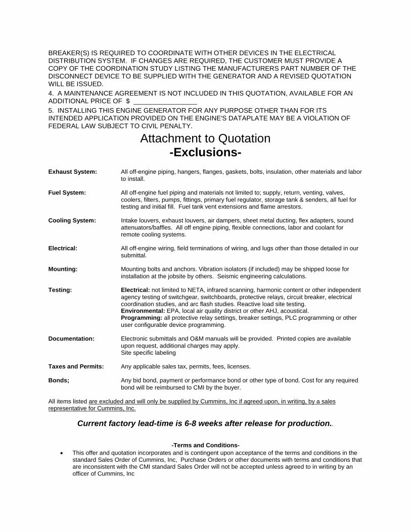
BREAKER(S) IS REQUIRED TO COORDINATE WITH OTHER DEVICES IN THE ELECTRICAL DISTRIBUTION SYSTEM. IF CHANGES ARE REQUIRED, THE CUSTOMER MUST PROVIDE A COPY OF THE COORDINATION STUDY LISTING THE MANUFACTURERS PART NUMBER OF THE DISCONNECT DEVICE TO BE SUPPLIED WITH THE GENERATOR AND A REVISED QUOTATION WILL BE ISSUED. 4. A MAINTENANCE AGREEMENT IS NOT INCLUDED IN THIS QUOTATION, AVAILABLE FOR ANADDITIONAL PRICE OF $ _________________ 5. INSTALLING THIS ENGINE GENERATOR FOR ANY PURPOSE OTHER THAN FOR ITSINTENDED APPLICATION PROVIDED ON THE ENGINE'S DATAPLATE MAY BE A VIOLATION OF FEDERAL LAW SUBJECT TO CIVIL PENALTY.
Attachment to Quotation -Exclusions-
Exhaust System: All off-engine piping, hangers, flanges, gaskets, bolts, insulation, other materials and labor to install.
Fuel System: All off-engine fuel piping and materials not limited to; supply, return, venting, valves, coolers, filters, pumps, fittings, primary fuel regulator, storage tank & senders, all fuel for testing and initial fill. Fuel tank vent extensions and flame arrestors.
Cooling System: Intake louvers, exhaust louvers, air dampers, sheet metal ducting, flex adapters, sound attenuators/baffles. All off engine piping, flexible connections, labor and coolant for remote cooling systems.
Electrical: All off-engine wiring, field terminations of wiring, and lugs other than those detailed in our submittal.
Mounting: Mounting bolts and anchors. Vibration isolators (if included) may be shipped loose for installation at the jobsite by others. Seismic engineering calculations.
Testing: Electrical: not limited to NETA, infrared scanning, harmonic content or other independent agency testing of switchgear, switchboards, protective relays, circuit breaker, electrical coordination studies, and arc flash studies. Reactive load site testing. Environmental: EPA, local air quality district or other AHJ, acoustical. Programming: all protective relay settings, breaker settings, PLC programming or other user configurable device programming.
Documentation: Electronic submittals and O&M manuals will be provided. Printed copies are available upon request, additional charges may apply. Site specific labeling
Taxes and Permits: Any applicable sales tax, permits, fees, licenses.
Bonds; Any bid bond, payment or performance bond or other type of bond. Cost for any required bond will be reimbursed to CMI by the buyer.
All items listed are excluded and will only be supplied by Cummins, Inc if agreed upon, in writing, by a sales representative for Cummins, Inc.
Current factory lead-time is 6-8 weeks after release for production..
-Terms and Conditions- • This offer and quotation incorporates and is contingent upon acceptance of the terms and conditions in the
standard Sales Order of Cummins, Inc, Purchase Orders or other documents with terms and conditions that are inconsistent with the CMI standard Sales Order will not be accepted unless agreed to in writing by an officer of Cummins, Inc
• Prices are valid for 30 days• If included in the quotation, all on-site startup, testing and training assumes weekdays, during standard CMI
business hours. Additional charges may be added for work requested to be done on overtime,weekends, and holidays.
• F.O.B. factory, freight allowed to first destination via common carrier, off-loading is not included• Factory direct shipments require credit approval prior to shipment• Terms are C.O.D., or 30 days upon approval of credit• Equipment held for longer than 30 days may be charged a monthly storage fee• Cancellation charges are 25% minimum after release of order
Submitted by
___________________________________________ Dennis Tarr , Electric Power Generation Sales [email protected] Mobile: 503-341-8597 Fax: 503-286-5938

Form #100804 rev 10/2011
Project Name:
Project Number:
Please review your installation and respond to the check list below: YES NO*1.2.3.
*4.*5.6.7.8.9.
10. or vapor withdrawal.11.
*12.13.
*14.15.16.17.18.
*19.20.
Recommended exhaust pipe material is schedule 40 black iron pipe.
The undersigned confirms equipment is ready for startup:
/ /Printed Name Signature Date Phone:Company: Fax:Phone #: Email Address:
Fax #:
Billie Hjort
If the equipment is not ready for start-up and testing, the installer will be responsible for a trip charge of $850. Start-up services will not be performed by Cummins Northwest, unless this form is returned a minimum of ten (10) business days before scheduled start-up.
Utility power available and connected to ATS / MTS (Don't connect door plug to harness)
Radiator discharge air exhaust duct installed.
Generator battery / batteries on site and connected with cables. (Do Not Energize Circuit)
Can emergency loads be transferred to generator at start-up?
Fuel Plumbing:
Interconnect Wiring:
Battery charger power connected (Do Not Energize Circuit)
Fuel available on-site and ready for testing.
Return to CNW Project Manager:
Gas plumbing and sizing completed in accordance with submittal specifications.
Propane tank set up for liquid
GENERATOR START-UP CHECK LIST
Owner / Tenant has been notified of the start-up date.
Generator mainline circuit breaker connected to ATS / MTS
425-235-3400 x3101425-235-8202
The information provided above is complete and accurate. By signing below the signatory agrees to reimburse CNW for all additional expenses incurred by CNW due to inaccurate or incomplete information.
Fuel day tank power connected. (Do Not Energize Circuit)
Intake and exhaust louvers installed and operational.
Engine coolant heater connected to utility (Do Not Energize Circuit)
Exhaust system installation complete including all piping and insulation.
Generator and isolators mounted to pad properly.
Remote radiator, piping, expansion tanks installed flushed, filled with coolant.
* Items 1, 4, 5, 12, 14 & 19 - Referenced wiring must be terminated without exception. CNW is not allowed by RCW 19.28 ,WAC 296-46A & WAC 296-401B to initially terminate this wiring. Once terminated, CNW can change or correct the wiring.
Recommended fuel line material for diesel systems is schedule 40 black iron pipe.
All interconnect wiring must be installed per Cummins Power Generation interconnect wiring drawing recommendations.
Exhaust Piping:
Fuel supply connected to engine with approved flexible lines.All DC and data interconnect wires run and terminated per submittal specifications.
Other: Note: training will take place during startup - advise required attendees of date and time upon scheduling.
Natural Gas and / or Propane plumbing requires a minimum 7"-13" of water column.
Cummins Northwest, LLC11134 W. Westbow Blvd. Spokane, WA 99224Phone (509) 455-4411Fax (509) 624-4681

Warranty Statement
Global Commercial Warranty Statement
Generator Set
EnglishOriginal Instructions 8-2013 A028U870 (Issue D)


Warranty StatementGlobal Power Electronics
Transfer Switch
EnglishOriginal Instructions 1-2015 A029Y876 Issue D

Effective Date: 01-Jan-2015 Page 1 of 2 A029Y876 Issue D
Limited Warranty Transfer Switch This limited warranty applies to all Cummins Power Generation branded Transfer Switches and associated accessories (hereinafter referred to as "Product"). This warranty covers any failures of the Product, under normal use and service, which result from a defect in material or factory workmanship.
Warranty Period: The warranty start date is the date of commissioning†, demonstration or 18 months after factory ship date, whichever is sooner.
† Date of commissioning not to exceed date of Generator Set initial
start-up.
Transfer Switch Coverage Duration: The warranty coverage duration for Transfer Switches is defined in the table below for the different product families:
Product Family Duration
GTEC, LT, LC,
RST, OTEC 1 Year: Parts, Labor & Travel
RSS, RA, and
other Pow er
Transfer Devices††
2 Years: Parts, Labor & Travel
OT, OTPC, BTPC,
OHPC, CHPC, PLT
Years 0-2: Parts, Labor &Travel
Years 3-5: Parts Only Years 6-10: Main Contacts Only
††
Devices manufactured by Cummins Power Generation that allow
power transfer between two power sources.
Cummins Power Generation Responsibilities: In the event of a failure of the Product during the warranty period due to defects in material or workmanship, Cummins Power Generation will only be responsible for the following costs:
Parts and labor required to repair the Product as defined by coverage duration.
Reasonable travel expenses to and from the Product site location as defined by coverage duration.
Owner Responsibilities: The owner will be responsible for the following:
Notifying Cummins Power Generation distributor or dealer within 30 days of the discovery of failure.
Installing, operating, commissioning and maintaining the Product in accordance with Cummins Power Generation’s published policies and guidelines.
Providing evidence for date of commissioning.
Providing sufficient access to and reasonable ability to remove the Product from the installation in the event of a warrantable failure.
In addition, the owner will be responsible for:
Incremental costs and expenses associated with Product removal and reinstallation resulting from non-standard installations.
Costs associated with rental of power generating equipment used to replace the Product being repaired.
Costs associated with labor overtime and premium shipping requested by the owner.
All downtime expenses, fines, all applicable taxes, and other losses resulting from a warrantable failure.

Effective Date: 01-Jan-2015 Page 2 of 2 A029Y876 Issue D
Limitations: This limited warranty does not cover Product failures resulting from:
Inappropriate use relative to designatedpower rating.
Inappropriate use relative to applicationguidelines.
Non-conformance to applicable industrystandards for installation
Normal wear and tear. Improper and/or unauthorized installation. Negligence, accidents or misuse. Lack of maintenance or unauthorized repair. Noncompliance with any Cummins Power
Generation published guideline or policy. Improper storage before and after
commissioning. Owner’s delay in making Product available
after notification of potential Product problem. Replacement parts and accessories not
authorized by Cummins Power Generation. Owner or operator abuse or neglect such as:
late servicing and maintenance and improperstorage.
Damage to parts, fixtures, housings,attachments and accessory items that arenot part of the transfer switch or parallelingsystem.
This limited warranty does not cover costs resulting from:
Difficulty in gaining access to the Product. Damage to customer property.
Please contact your local Cummins Power
Generation Distributor for clarification concerning these limitations.
CUMMINS POWER GENERATION RIGHT TO FAILED COMPONENTS: Failed components claimed under warranty remain the property of Cummins Power Generation. Cummins Power Generation has the right to reclaim any failed component that has been replaced under warranty.
Extended Warranty: Cummins Power Generation offers several levels of Extended Warranty Coverage. Please contact your
local Cummins Power Generation Distributor for details.
www.power.cummins.com
THE WARRANTIES SET FORTH HEREIN ARE THE SOLE WARRANTIES MADE BY CUMMINS POWER GENERATION IN REGARD TO THE
PRODUCT. CUMMINS POWER GENERATION MAKES NO OTHER WARRANTIES, EXPRESS OR IMPLIED, OR OF MERCHANTABILITY OR FITNESS FOR A PARTICULAR PURPOSE.
IN NO EVENT IS CUMMINS POWER
GENERATION LIABLE FOR INCIDENTAL OR CONSEQUENTIAL DAMAGES.
This limited warranty shall be enforced to the maximum extent permitted by applicable law. This limited warranty gives the owner specific rights that may vary from state to state or from jurisdiction to jurisdiction.
Product Model Number:_______________________
Product Serial Number:________________________
Date in Service:______________________________

power.cummins.com ©2016 Cummins Power Generation Inc. | NAS-6211a-EN (9/16)
Specification sheet
Diesel generator set QSB5 series engine
50-125 kW @ 60Hz EPA Tier 3 emissions
Description Cummins Power Generation generator sets are fully integrated power generation systems providing optimum performance, reliability and versatility for stationary standby applications.
Features Heavy Duty Engine - Rugged 4-cycle industrial diesel delivers reliable power and fast response to load changes. Alternator - Several alternator sizes offer selectable motor starting capability with low reactance 2/3 pitch windings, low waveform distortion with non-linear loads and fault clearing short-circuit capability. Control system - The PowerCommand® 2.3 electronic control is standard equipment and provides total generator set system integration including automatic remote starting/stopping, precise frequency and voltage regulation, alarm and status message display, output metering, auto-shutdown at fault detection and NFPA 110 Level 1 compliance.
Cooling system - Standard cooling package provides reliable running at up to 50 °C (122 °F) ambient temperature. Enclosures - The aesthetically appealing enclosure incorporates special designs that deliver one of the quietest generators of its kind. Aluminum material plus durable powder coat paint provides the best anti-corrosion performance. The generator set enclosure has been designed to withstand 180 MPH wind loads in accordance with ASCE7-10. The design has hinged doors to provide easy access for service and maintenance. Fuel tanks - Dual wall sub-base fuel tanks are offered as optional features, providing economical and flexible solutions to meet extensive code requirements on diesel fuel tanks. NFPA - The generator set accepts full rated load in a single step in accordance with NFPA 110 for Level 1 systems. Warranty and service - Backed by a comprehensive warranty and worldwide distributor and dealer network.
Standby 60 Hz
Prime 60 Hz Data sheets
Model kW kVA kW kVA C50D6C 50 63 45 56 NAD-6212-EN C60D6C 60 75 54 68 NAD-6213-EN C80D6C 80 100 72 90 NAD-6214-EN C100D6C 100 125 90 113 NAD-6215-EN C125D6C 125 156 112.5 141 NAD-6216-EN
power.cummins.com ©2016 Cummins Power Generation Inc. | NAS-6211a-EN (9/16)
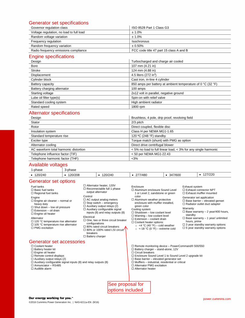
Generator set specifications Governor regulation class ISO 8528 Part 1 Class G3 Voltage regulation, no load to full load ± 1.0% Random voltage variation ± 1.0% Frequency regulation Isochronous Random frequency variation ± 0.50% Radio frequency emissions compliance FCC code title 47 part 15 class A and B
Engine specifications Design Turbocharged and charge air cooled Bore 107 mm (4.21 in) Stroke 124 mm (4.88 in) Displacement 4.5 liters (272 in3) Cylinder block Cast iron, in-line 4 cylinder Battery capacity 850 amps per battery at ambient temperature of 0 °C (32 °F) Battery charging alternator 100 amps Starting voltage 2x12 volt in parallel, negative ground Lube oil filter type(s) Spin-on with relief valve Standard cooling system High ambient radiator Rated speed 1800 rpm
Alternator specifications Design Brushless, 4 pole, drip proof, revolving field Stator 2/3 pitch Rotor Direct coupled, flexible disc Insulation system Class H per NEMA MG1-1.65 Standard temperature rise 120 ºC (248 °F) standby Exciter type Torque match (shunt) with PMG as option Alternator cooling Direct drive centrifugal blower AC waveform total harmonic distortion < 5% no load to full linear load, < 3% for any single harmonic Telephone influence factor (TIF) < 50 per NEMA MG1-22.43 Telephone harmonic factor (THF) <3%
Available voltages 1-phase 3-phase • 120/240 • 120/208 • 120/240 • 277/480 • 347/600 • 127/220
Generator set options Fuel tanks Basic fuel tanks Regional fuel tanks Engine Engine air cleaner – normal or
heavy duty Shut down – low oil pressure Extension – oil drain Engine oil heater Alternator 120 °C temperature rise alternator 105 °C temperature rise alternator PMG excitation
Alternator heater, 120V Reconnectable full 1 phase
output alternator Control AC output analog meters Stop switch – emergency Auxiliary output relays (2) Auxiliary configurable signal
inputs (8) and relay outputs (8) Electrical One, two or three circuit breaker
configurations 80% rated circuit breakers 80% or 100% rated LSI circuit
breakers Battery charger
Enclosure Aluminum enclosure Sound Level
1 or Level 2, sandstone or green color
Aluminum weather protective enclosure with muffler installed, green color
Cooling system Shutdown – low coolant level Warning – low coolant level Extension – coolant drain Coolant heater options:
o <4 °C (40 °F) – cold weather o <-18 °C (0 °F) – extreme cold
Exhaust system Exhaust connector NPT Exhaust muffler mounted Generator set application Base barrier – elevated genset Radiator outlet duct adapter Warranty Base warranty – 2 year/400 hours,
standby Base warranty – 1 year/ unlimited
hours, prime 3 year standby warranty options 5 year standby warranty options
Generator set accessories Coolant heater Battery heater kit Engine oil heater Remote control displays Auxiliary output relays (2) Auxiliary configurable signal inputs (8) and relay outputs (8) Annunciator – RS485 Audible alarm
Remote monitoring device – PowerCommand® 500/550 Battery charger – stand-alone, 12V Circuit breakers Enclosure Sound Level 1 to Sound Level 2 upgrade kit Base barrier – elevated generator set Mufflers – industrial, residential or critical Alternator PMG excitation Alternator heater
See proposal for options included

power.cummins.com ©2016 Cummins Power Generation Inc. | NAS-6211a-EN (9/16)
Control system PowerCommand 2.3 PowerCommand® 2.3 control - An integrated generator set control system providing voltage regulation, engine protection and operator interface. Control - Provides battery monitoring and testing features and smart-starting control system. InPower™ – PC-based service tool available for detailed diagnostics. PCCNet RS485 - Network interface (standard) to devices such as remote annunciator for NFPA 110 applications. Control boards - Potted for environmental protection. Ambient operation - Suitable for operation in ambienet temperatures from -40°C to +70°C and altitudes to 13,000 feet (5,000 meters). AC Protection • AmpSentry protective relay • Over current warning and shutdown • Over and under voltage shutdown • Over and under frequency shutdown • Over excitation (loss of sensing) fault • Field overload • Overload warning • Reverse kW shutdown • Reverse VAR shutdown • Short circuit protection Engine protection • Overspeed shutdown • Low oil pressure warning and shutdown • High coolant temperature warning and shutdown • Low coolant level warning or shutdown • Low coolant temperature warning • High, low and weak battery voltage warning • Fail to start (overcrank) shutdown • Fail to crank shutdown • Redundant start disconnect • Cranking lockout • Sensor failure indication • Low fuel level warning or shutdown • Emergency stop • Fuel-in-rupture-basin warning or shutdown Operator/display panel • Manual off switch • 320 x 240 Pixels graphic LED backlight LCD with
push button access for viewing engine and alternator data and providing setup, controls, and adjustments (English, Spanish, or French).
• LED lamps indicating genset running, not in auto, common warning, common shutdown, manual run mode and remote start
• Suitable for operation in ambient temperatures from -20°C to +70°C
Alternator data • Line-to-line and Line-to-neutral AC volts • 3-phase AC current • Frequency • kVa, kW, power factor Engine data • DC voltage • Lube oil pressure • Coolant temperature Other data • Generator set model data • Start attempts, starts, running hours • Fault history • RS485 Modbus® interface • Data logging and fault simulation (requires InPower™
service tool) Digital voltage regulation • Integrated digital electronic voltage regulator • 3-phase line-to-line sensing • Configurable torque matching • Fault current regulation under single or three phase
fault conditions Control functions • Time delay start and cooldown • Cycle cranking • PCCNet interface • (2) Configurable inputs • (2) Configurable outputs • Remote emergency stop • Automatic transfer switch (ATS) control • Generator set exercise, field adjustable Options Auxiliary output relays (2) Remote annunciator with (3) configurable inputs and
(4) configurable outputs PMG alternator excitation PowerCommand 500/550 for remote monitoring and
alarm notification (accessory) Auxiliary, configurable signal inputs (8) and
configurable relay outputs (8) AC output analog meters (bargraph)
- Color-coded graphical display of: - 3-phase AC voltage - 3-phase current - Frequency - kVa
Remote operator panel
power.cummins.com ©2016 Cummins Power Generation Inc. | NAS-6211a-EN (9/16)
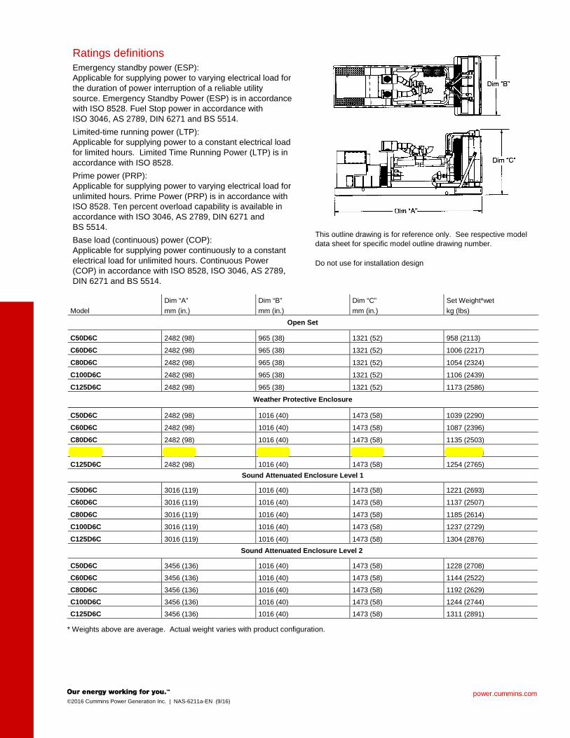
Ratings definitions Emergency standby power (ESP): Applicable for supplying power to varying electrical load for the duration of power interruption of a reliable utility source. Emergency Standby Power (ESP) is in accordance with ISO 8528. Fuel Stop power in accordance with ISO 3046, AS 2789, DIN 6271 and BS 5514. Limited-time running power (LTP): Applicable for supplying power to a constant electrical load for limited hours. Limited Time Running Power (LTP) is in accordance with ISO 8528. Prime power (PRP): Applicable for supplying power to varying electrical load for unlimited hours. Prime Power (PRP) is in accordance with ISO 8528. Ten percent overload capability is available in accordance with ISO 3046, AS 2789, DIN 6271 and BS 5514. Base load (continuous) power (COP): Applicable for supplying power continuously to a constant electrical load for unlimited hours. Continuous Power (COP) in accordance with ISO 8528, ISO 3046, AS 2789, DIN 6271 and BS 5514.
This outline drawing is for reference only. See respective model data sheet for specific model outline drawing number. Do not use for installation design
Model Dim “A” mm (in.)
Dim “B” mm (in.)
Dim “C” mm (in.)
Set Weight*wet kg (lbs)
Open Set
C50D6C 2482 (98) 965 (38) 1321 (52) 958 (2113)
C60D6C 2482 (98) 965 (38) 1321 (52) 1006 (2217)
C80D6C 2482 (98) 965 (38) 1321 (52) 1054 (2324)
C100D6C 2482 (98) 965 (38) 1321 (52) 1106 (2439)
C125D6C 2482 (98) 965 (38) 1321 (52) 1173 (2586)
Weather Protective Enclosure
C50D6C 2482 (98) 1016 (40) 1473 (58) 1039 (2290)
C60D6C 2482 (98) 1016 (40) 1473 (58) 1087 (2396)
C80D6C 2482 (98) 1016 (40) 1473 (58) 1135 (2503)
C100D6C 2482 (98) 1016 (40) 1473 (58) 1187 (2618)
C125D6C 2482 (98) 1016 (40) 1473 (58) 1254 (2765) Sound Attenuated Enclosure Level 1
C50D6C 3016 (119) 1016 (40) 1473 (58) 1221 (2693)
C60D6C 3016 (119) 1016 (40) 1473 (58) 1137 (2507)
C80D6C 3016 (119) 1016 (40) 1473 (58) 1185 (2614)
C100D6C 3016 (119) 1016 (40) 1473 (58) 1237 (2729)
C125D6C 3016 (119) 1016 (40) 1473 (58) 1304 (2876) Sound Attenuated Enclosure Level 2
C50D6C 3456 (136) 1016 (40) 1473 (58) 1228 (2708) C60D6C 3456 (136) 1016 (40) 1473 (58) 1144 (2522) C80D6C 3456 (136) 1016 (40) 1473 (58) 1192 (2629) C100D6C 3456 (136) 1016 (40) 1473 (58) 1244 (2744) C125D6C 3456 (136) 1016 (40) 1473 (58) 1311 (2891)
* Weights above are average. Actual weight varies with product configuration.

North America 1400 73rd Avenue N.E. Minneapolis, MN 55432 USA Phone 763 574 5000 Fax 763 574 5298
©2016 Cummins Power Generation Inc. All rights reserved. Cummins Power Generation and Cummins are registered trademarks of Cummins Inc. PowerCommand, AmpSentry, InPower and “Our energy working for you.” are trademarks of Cummins Power Generation. Other company, product, or service names may be trademarks or service marks of others. Specifications are subject to change without notice. NAS-6211a-EN (9/16)
power.cummins.com
Codes and standards Codes or standards compliance may not be available with all model configurations – consult factory for availability.
The Prototype Test Support (PTS) program verifies the performance integrity of the generator set design. Cummins Power Generation products bearing the PTS symbol meet the prototype test requirements of NFPA 110 for Level 1 systems.
This generator set is designed in facilities certified to ISO 9001 and manufactured in facilities certified to ISO 9001 or ISO 9002.
The generator set is available Listed to UL 2200, Stationary Engine Generator Assemblies.
International Building Code
The generator set is certified to International Building Code (IBC) 2012.
All low voltage models are CSA certified to product class 4215-01.
U.S. EPA Engine certified to U.S. EPA SI Stationary Emission Regulation 40 CFR, Part 60.
Warning: Back feed to a utility system can cause electrocution and/or property damage. Do not connect to any building’s electrical system except through an approved device or after building main switch is open.
power.cummins.com ©2016 Cummins Power Generation Inc. | NAD-6215a-EN (9/16)
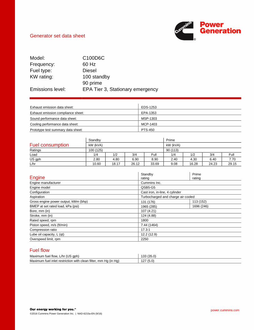
Generator set data sheet
Model: Frequency: Fuel type: KW rating: Emissions level:
C100D6C 60 Hz Diesel 100 standby 90 prime EPA Tier 3, Stationary emergency
Exhaust emission data sheet: EDS-1253 Exhaust emission compliance sheet: EPA-1353 Sound performance data sheet: MSP-1303 Cooling performance data sheet: MCP-1403 Prototype test summary data sheet: PTS-450
Fuel consumption Standby Prime kW (kVA) kW (kVA)
Ratings 100 (125) 90 (113) Load 1/4 1/2 3/4 Full 1/4 1/2 3/4 Full US gph 2.80 4.80 6.90 8.90 2.40 4.30 6.40 7.70 L/hr 10.60 18.17 26.12 33.69 9.08 16.28 24.23 29.15
Engine Standby rating
Prime rating
Engine manufacturer Cummins Inc. Engine model QSB5-G5 Configuration Cast iron, in-line, 4 cylinder Aspiration Turbocharged and charge air cooled Gross engine power output, kWm (bhp) 131 (176) 113 (152) BMEP at set rated load, kPa (psi) 1965 (285) 1696 (246) Bore, mm (in) 107 (4.21) Stroke, mm (in) 124 (4.88) Rated speed, rpm 1800 Piston speed, m/s (ft/min) 7.44 (1464) Compression ratio 17.3:1 Lube oil capacity, L (qt) 12.2 (12.9) Overspeed limit, rpm 2250
Fuel flow Maximum fuel flow, L/hr (US gph) 133 (35.0) Maximum fuel inlet restriction with clean filter, mm Hg (in Hg) 127 (5.0)

©2010 Cummins Power Generation Inc. All rights reserved. Cummins Power Generation and Cummins are registered trademarks of Cummins Inc. PowerCommand, AmpSentry, InPower and “Our energy working for you.” are trademarks of Cummins Power Generation. Other company, product, or service names may be trademarks or service marks of others. Specifications are subject to change without notice. S-1569a (5/10) Page 1 of 7
PowerCommand®
2.3 control system
Control system description Features The PowerCommand® control system is a microprocessor-based generator set monitoring, metering and control system designed to meet the demands of today’s engine driven generator sets. The integration of all control functions into a single control system provides enhanced reliability and performance, compared to conventional generator set control systems. These control systems have been designed and tested to meet the harsh environment in which gensets are typically applied.
• 320 x 240 pixels graphic LED backlight LCD.
• Multiple language support.
• AmpSentry™ Protective Relay - True alternator overcurrent protection.
• Real time clock for fault and event time stamping.
• Exerciser clock and time of day start/stop.
• Digital voltage regulation. Three phase full wave FET type regulator compatible with either shunt or PMG systems.
• Generator set monitoring and protection.
• 12 and 24 VDC battery operation.
• Modbus® interface for interconnecting to customer equipment.
• Warranty and service. Backed by a comprehensive warranty and worldwide distributor service network.
• Certifications - Suitable for use on generator sets that are designed, manufactured, tested and certified to relevant UL, NFPA, ISO, IEC, Mil Std., CE and CSA standards.
Our energy working for you.™
www.cumminspower.com ©2010 Cummins Power Generation Inc. All rights reserved. Cummins Power Generation and Cummins are registered trademarks of Cummins Inc. PowerCommand, AmpSentry, InPower and “Our energy working for you.” are trademarks of Cummins Power Generation. Other company, product, or service names may be trademarks or service marks of others. Specifications are subject to change without notice. S-1569a (5/10) Page 2 of 7
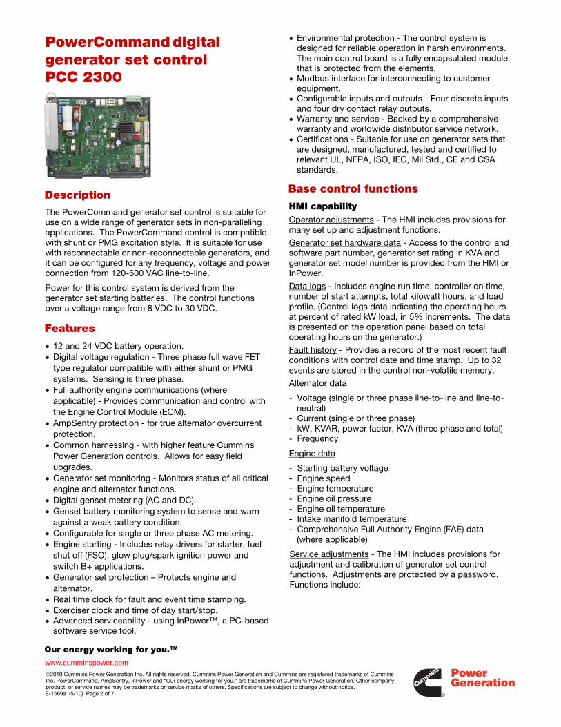
PowerCommand digital generator set control PCC 2300
Description The PowerCommand generator set control is suitable for use on a wide range of generator sets in non-paralleling applications. The PowerCommand control is compatible with shunt or PMG excitation style. It is suitable for use with reconnectable or non-reconnectable generators, and it can be configured for any frequency, voltage and power connection from 120-600 VAC line-to-line.
Power for this control system is derived from the generator set starting batteries. The control functions over a voltage range from 8 VDC to 30 VDC.
Features
• 12 and 24 VDC battery operation. • Digital voltage regulation - Three phase full wave FET
type regulator compatible with either shunt or PMG systems. Sensing is three phase.
• Full authority engine communications (where applicable) - Provides communication and control with the Engine Control Module (ECM).
• AmpSentry protection - for true alternator overcurrent protection.
• Common harnessing - with higher feature Cummins Power Generation controls. Allows for easy field upgrades.
• Generator set monitoring - Monitors status of all critical engine and alternator functions.
• Digital genset metering (AC and DC). • Genset battery monitoring system to sense and warn
against a weak battery condition. • Configurable for single or three phase AC metering. • Engine starting - Includes relay drivers for starter, fuel
shut off (FSO), glow plug/spark ignition power and switch B+ applications.
• Generator set protection – Protects engine and alternator.
• Real time clock for fault and event time stamping. • Exerciser clock and time of day start/stop. • Advanced serviceability - using InPower™, a PC-based
software service tool.
• Environmental protection - The control system is designed for reliable operation in harsh environments. The main control board is a fully encapsulated module that is protected from the elements.
• Modbus interface for interconnecting to customer equipment.
• Configurable inputs and outputs - Four discrete inputs and four dry contact relay outputs.
• Warranty and service - Backed by a comprehensive warranty and worldwide distributor service network.
• Certifications - Suitable for use on generator sets that are designed, manufactured, tested and certified to relevant UL, NFPA, ISO, IEC, Mil Std., CE and CSA standards.
Base control functions
HMI capability Operator adjustments - The HMI includes provisions for many set up and adjustment functions.
Generator set hardware data - Access to the control and software part number, generator set rating in KVA and generator set model number is provided from the HMI or InPower.
Data logs - Includes engine run time, controller on time, number of start attempts, total kilowatt hours, and load profile. (Control logs data indicating the operating hours at percent of rated kW load, in 5% increments. The data is presented on the operation panel based on total operating hours on the generator.)
Fault history - Provides a record of the most recent fault conditions with control date and time stamp. Up to 32 events are stored in the control non-volatile memory.
Alternator data
- Voltage (single or three phase line-to-line and line-to-neutral)
- Current (single or three phase) - kW, KVAR, power factor, KVA (three phase and total) - Frequency
Engine data
- Starting battery voltage - Engine speed - Engine temperature - Engine oil pressure - Engine oil temperature - Intake manifold temperature - Comprehensive Full Authority Engine (FAE) data
(where applicable)
Service adjustments - The HMI includes provisions for adjustment and calibration of generator set control functions. Adjustments are protected by a password. Functions include:
Our energy working for you.™
www.cumminspower.com ©2010 Cummins Power Generation Inc. All rights reserved. Cummins Power Generation and Cummins are registered trademarks of Cummins Inc. PowerCommand, AmpSentry, InPower and “Our energy working for you.” are trademarks of Cummins Power Generation. Other company, product, or service names may be trademarks or service marks of others. Specifications are subject to change without notice. S-1569a (5/10) Page 3 of 7
Service adjustments (continued) - Engine speed governor adjustments - Voltage regulation adjustments - Cycle cranking - Configurable fault set up - Configurable output set up - Meter calibration - Display language and units of measurement
Engine control
SAE-J1939 CAN interface to full authority ECMs (where applicable). Provides data swapping between genset and engine controller for control, metering and diagnostics.
12 VDC/24 VDC battery operations - PowerCommand will operate either on 12 VDC or 24 VDC batteries. Temperature dependent governing dynamics (with electronic governing) - modifies the engine governing control parameters as a function of engine temperature. This allows the engine to be more responsive when warm and more stable when operating at lower temperature levels.
Isochronous governing - (where applicable) Capable of controlling engine speed within +/-0.25% for any steady state load from no load to full load. Frequency drift will not exceed +/-0.5% for a 33 °C (60 °F) change in ambient temperature over an 8 hour period.
Droop electronic speed governing - Control can be adjusted to droop from 0 to 10% from no load to full load.
Remote start mode - It accepts a ground signal from remote devices to automatically start the generator set and immediately accelerate to rated speed and voltage. The remote start signal will also wake up the control from sleep mode. The control can incorporate a time delay start and stop.
Remote and local emergency stop - The control accepts a ground signal from a local (genset mounted) or remote (facility mounted) emergency stop switch to cause the generator set to immediately shut down. The generator set is prevented from running or cranking with the switch engaged. If in sleep mode, activation of either emergency stop switch will wakeup the control.
Sleep mode - The control includes a configurable low current draw state to minimize starting battery current draw when the genset is not operating. The control can also be configured to go into a low current state while in auto for prime applications or applications without a battery charger.
Engine starting - The control system supports automatic engine starting. Primary and backup start disconnects are achieved by one of two methods: magnetic pickup or main alternator output frequency. The control also supports configurable glow plug control when applicable.
Cycle cranking - Is configurable for the number of starting cycles (1 to 7) and duration of crank and rest
periods. Control includes starter protection algorithms to prevent the operator from specifying a starting sequence that might be damaging.
Time delay start and stop (cooldown) - Configurable for time delay of 0-300 seconds prior to starting after receiving a remote start signal and for time delay of 0-600 seconds prior to shut down after signal to stop in normal operation modes. Default for both time delay periods is 0 seconds.
Alternator control
The control includes an integrated three phase line-to-line sensing voltage regulation system that is compatible with shunt or PMG excitation systems. The voltage regulation system is a three phase full wave rectified and has an FET output for good motor starting capability. Major system features include:
Digital output voltage regulation - Capable of regulating output voltage to within +/-1.0% for any loads between no load and full load. Voltage drift will not exceed +/-1.5% for a 40 ºC (104 ºF) change in temperature in an eight hour period. On engine starting or sudden load acceptance, voltage is controlled to a maximum of 5% overshoot over nominal level. The automatic voltage regulator feature can be disabled to allow the use of an external voltage regulator.
Droop voltage regulation - Control can be adjusted to droop from 0-10% from no load to full load.
Torque-matched V/Hz overload control - The voltage roll-off set point and rate of decay (i.e. the slope of the V/Hz curve) is adjustable in the control.
Fault current regulation - PowerCommand will regulate the output current on any phase to a maximum of three times rated current under fault conditions for both single phase and three phase faults. In conjunction with a permanent magnet generator, it will provide three times rated current on all phases for motor starting and short circuit coordination purpose.
Protective functions On operation of a protective function the control will indicate a fault by illuminating the appropriate status LED on the HMI, as well as display the fault code and fault description on the LCD. The nature of the fault and time of occurrence are logged in the control. The service manual and InPower service tool provide service keys and procedures based on the service codes provided. Protective functions include:
Battle short mode
When enabled and the battle short switch is active, the control will allow some shutdown faults to be bypassed. If a bypassed shutdown fault occurs, the fault code and description will still be annunciated, but the genset will
Our energy working for you.™
www.cumminspower.com ©2010 Cummins Power Generation Inc. All rights reserved. Cummins Power Generation and Cummins are registered trademarks of Cummins Inc. PowerCommand, AmpSentry, InPower and “Our energy working for you.” are trademarks of Cummins Power Generation. Other company, product, or service names may be trademarks or service marks of others. Specifications are subject to change without notice. S-1569a (5/10) Page 4 of 7
not shutdown. This will be followed by a fail to shutdown fault. Emergency stop shutdowns and others that are critical for proper operation are not bypassed. Please refer to the Control Application Guide or Manual for list of these faults.
Derate
The Derate function reduces output power of the genset in response to a fault condition. If a Derate command occurs while operating on an isolated bus, the control will issue commands to reduce the load on the genset via contact closures or Modbus. Configurable alarm and status inputs
The control accepts up to four alarm or status inputs (configurable contact closed to ground or open) to indicate a configurable (customer-specified) condition.
The control is programmable for warning, shutdown or status indication and for labeling the input.
Emergency stop
Annunciated whenever either emergency stop signal is received from external switch.
Full authority electronic engine protection
Engine fault detection is handled inside the engine ECM. Fault information is communicated via the SAE-J1939 data link for annunciation in the HMI.
General engine protection
Low and high battery voltage warning - Indicates status of battery charging system (failure) by continuously monitoring battery voltage.
Weak battery warning - The control system will test the battery each time the generator set is signaled to start and indicate a warning if the battery indicates impending failure.
Fail to start (overcrank) shutdown - The control system will indicate a fault if the generator set fails to start by the completion of the engine crack sequence.
Fail to crank shutdown - Control has signaled starter to crank engine but engine does not rotate.
Cranking lockout - The control will not allow the starter to attempt to engage or to crank the engine when the engine is rotating.
Alternator protection
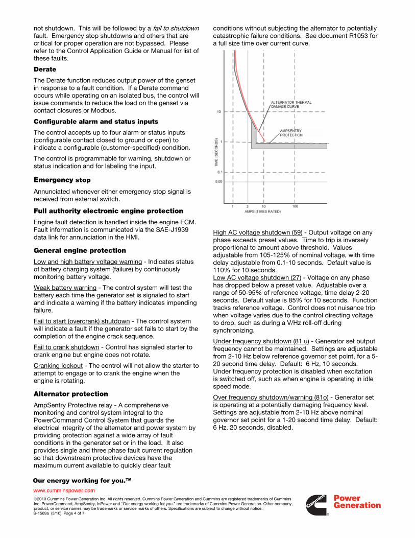
AmpSentry Protective relay - A comprehensive monitoring and control system integral to the PowerCommand Control System that guards the electrical integrity of the alternator and power system by providing protection against a wide array of fault conditions in the generator set or in the load. It also provides single and three phase fault current regulation so that downstream protective devices have the maximum current available to quickly clear fault
conditions without subjecting the alternator to potentially catastrophic failure conditions. See document R1053 for a full size time over current curve.
High AC voltage shutdown (59) - Output voltage on any phase exceeds preset values. Time to trip is inversely proportional to amount above threshold. Values adjustable from 105-125% of nominal voltage, with time delay adjustable from 0.1-10 seconds. Default value is 110% for 10 seconds. Low AC voltage shutdown (27) - Voltage on any phase has dropped below a preset value. Adjustable over a range of 50-95% of reference voltage, time delay 2-20 seconds. Default value is 85% for 10 seconds. Function tracks reference voltage. Control does not nuisance trip when voltage varies due to the control directing voltage to drop, such as during a V/Hz roll-off during synchronizing.
Under frequency shutdown (81 u) - Generator set output frequency cannot be maintained. Settings are adjustable from 2-10 Hz below reference governor set point, for a 5-20 second time delay. Default: 6 Hz, 10 seconds. Under frequency protection is disabled when excitation is switched off, such as when engine is operating in idle speed mode.
Over frequency shutdown/warning (81o) - Generator set is operating at a potentially damaging frequency level. Settings are adjustable from 2-10 Hz above nominal governor set point for a 1-20 second time delay. Default: 6 Hz, 20 seconds, disabled.
Our energy working for you.™
www.cumminspower.com ©2010 Cummins Power Generation Inc. All rights reserved. Cummins Power Generation and Cummins are registered trademarks of Cummins Inc. PowerCommand, AmpSentry, InPower and “Our energy working for you.” are trademarks of Cummins Power Generation. Other company, product, or service names may be trademarks or service marks of others. Specifications are subject to change without notice. S-1569a (5/10) Page 5 of 7
Overcurrent warning/shutdown - Thresholds and time delays are configurable. Implementation of the thermal damage curve with instantaneous trip level calculated based on current transformer ratio and application power rating.
Loss of sensing voltage shutdown - Shutdown of generator set will occur on loss of voltage sensing inputs to the control.
Field overload shutdown - Monitors field voltage to shutdown generator set when a field overload condition occurs.
Over load (kW) warning - Provides a warning indication when engine is operating at a load level over a set point. Adjustment range: 80-140% of application rated kW, 0-120 second delay. Defaults: 105%, 60 seconds.
Reverse power shutdown (32) - Adjustment range: 5-20% of standby kW rating, delay 1-15 seconds. Default: 10%, 3 seconds.
Reverse Var shutdown - Shutdown level is adjustable: 15-50% of rated Var output, delay 10-60 seconds. Default: 20%, 10 seconds.
Short circuit protection - Output current on any phase is more than 175% of rating and approaching the thermal damage point of the alternator. Control includes algorithms to protect alternator from repeated over current conditions over a short period of time.
Field control interface Input signals to the PowerCommand control include:
- Coolant level (where applicable) - Fuel level (where applicable) - Remote emergency stop - Remote fault reset - Remote start - Battleshort - Rupture basin - Start type signal - Configurable inputs - Control includes (4) input signals
from customer discrete devices that are configurable for warning, shutdown or status indication, as well as message displayed
Output signals from the PowerCommand control include:
- Load dump signal: Operates when the generator set is in an overload condition.
- Delayed off signal: Time delay based output which will continue to remain active after the control has removed the run command. Adjustment range: 0 - 120 seconds. Default: 0 seconds.
- Configurable relay outputs: Control includes (4) relay output contacts (3 A, 30VDC). These outputs can be configured to activate on any control warning or shutdown fault as well as ready to load, not in auto, common alarm, common warning and common shutdown.
- Ready to load (generator set running) signal: Operates when the generator set has reached 90% of rated speed and voltage and latches until generator set is switched to off or idle mode.
Communications connections include:
- PC tool interface: This RS-485 communication port allows the control to communicate with a personal computer running InPower software.
- Modbus RS-485 port: Allows the control to communicate with external devices such as PLCs using Modbus protocol.
Note - An RS-232 or USB to RS-485 converter is required for communication between PC and control.
- Networking: This RS-485 communication port allows connection from the control to the other Cummins Power Generation products.
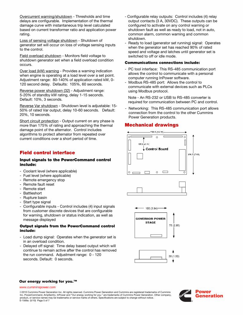
Mechanical drawings
Our energy working for you.™
www.cumminspower.com ©2010 Cummins Power Generation Inc. All rights reserved. Cummins Power Generation and Cummins are registered trademarks of Cummins Inc. PowerCommand, AmpSentry, InPower and “Our energy working for you.” are trademarks of Cummins Power Generation. Other company, product, or service names may be trademarks or service marks of others. Specifications are subject to change without notice. S-1569a (5/10) Page 6 of 7
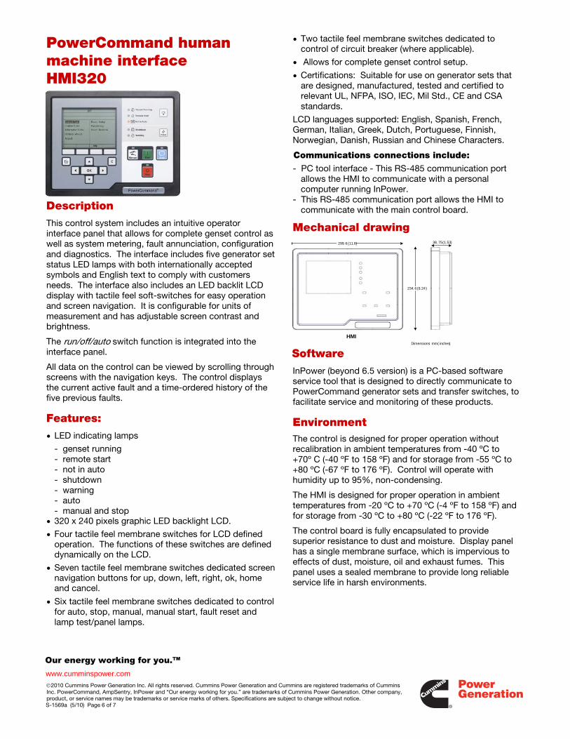
PowerCommand human machine interface HMI320
Description This control system includes an intuitive operator interface panel that allows for complete genset control as well as system metering, fault annunciation, configuration and diagnostics. The interface includes five generator set status LED lamps with both internationally accepted symbols and English text to comply with customers needs. The interface also includes an LED backlit LCD display with tactile feel soft-switches for easy operation and screen navigation. It is configurable for units of measurement and has adjustable screen contrast and brightness.
The run/off/auto switch function is integrated into the interface panel.
All data on the control can be viewed by scrolling through screens with the navigation keys. The control displays the current active fault and a time-ordered history of the five previous faults.
Features: • LED indicating lamps
- genset running - remote start - not in auto - shutdown - warning - auto - manual and stop
• 320 x 240 pixels graphic LED backlight LCD.
• Four tactile feel membrane switches for LCD defined operation. The functions of these switches are defined dynamically on the LCD.
• Seven tactile feel membrane switches dedicated screen navigation buttons for up, down, left, right, ok, home and cancel.
• Six tactile feel membrane switches dedicated to control for auto, stop, manual, manual start, fault reset and lamp test/panel lamps.
• Two tactile feel membrane switches dedicated to control of circuit breaker (where applicable).
• Allows for complete genset control setup.
• Certifications: Suitable for use on generator sets that are designed, manufactured, tested and certified to relevant UL, NFPA, ISO, IEC, Mil Std., CE and CSA standards.
LCD languages supported: English, Spanish, French, German, Italian, Greek, Dutch, Portuguese, Finnish, Norwegian, Danish, Russian and Chinese Characters.
Communications connections include:
- PC tool interface - This RS-485 communication port allows the HMI to communicate with a personal computer running InPower.
- This RS-485 communication port allows the HMI to communicate with the main control board.
Mechanical drawing 299. 6 (11.8)
234. 6 (9.24)
38. 75 (1.53)
HMIDimensions: mm ( inches)
Software
InPower (beyond 6.5 version) is a PC-based software service tool that is designed to directly communicate to PowerCommand generator sets and transfer switches, to facilitate service and monitoring of these products.
Environment The control is designed for proper operation without recalibration in ambient temperatures from -40 ºC to +70º C (-40 ºF to 158 ºF) and for storage from -55 ºC to +80 ºC (-67 ºF to 176 ºF). Control will operate with humidity up to 95%, non-condensing.
The HMI is designed for proper operation in ambient temperatures from -20 ºC to +70 ºC (-4 ºF to 158 ºF) and for storage from -30 ºC to +80 ºC (-22 ºF to 176 ºF).
The control board is fully encapsulated to provide superior resistance to dust and moisture. Display panel has a single membrane surface, which is impervious to effects of dust, moisture, oil and exhaust fumes. This panel uses a sealed membrane to provide long reliable service life in harsh environments.
Our energy working for you.™
www.cumminspower.com ©2010 Cummins Power Generation Inc. All rights reserved. Cummins Power Generation and Cummins are registered trademarks of Cummins Inc. PowerCommand, AmpSentry, InPower and “Our energy working for you.” are trademarks of Cummins Power Generation. Other company, product, or service names may be trademarks or service marks of others. Specifications are subject to change without notice. S-1569a (5/10) Page 7 of 7
The control system is specifically designed and tested for resistance to RFI/EMI and to resist effects of vibration to provide a long reliable life when mounted on a generator set. The control includes transient voltage surge suppression to provide compliance to referenced standards.
Certifications
PowerCommand meets or exceeds the requirements of the following codes and standards:
- NFPA 110 for level 1 and 2 systems. - ISO 8528-4: 1993 compliance, controls and
switchgear. - CE marking: The control system is suitable for use on
generator sets to be CE-marked. - EN 50081-1,2 residential/light industrial emissions or
industrial emissions. - EN 50082-1,2 residential/light industrial or industrial
susceptibility. - ISO 7637-2, level 2; DC supply surge voltage test. - Mil Std 202C, Method 101 and ASTM B117: Salt fog
test. - UL 508 recognized or Listed and suitable for use on UL
2200 Listed generator sets. - CSA C282-M1999 compliance - CSA 22.2 No. 14 M91 industrial controls. - PowerCommand control systems and generator sets
are designed and manufactured in ISO 9001 certified facilities.
Warranty All components and subsystems are covered by an express limited one year warranty. Other optional and extended factory warranties and local distributor maintenance agreements are available.
See your distributor for more information Cummins Power Generation Americas 1400 73rd Avenue N.E. Minneapolis, MN 55432 USA Phone: 763 574 5000 Fax: 763 574 5298
Europe, CIS, Middle East and Africa Manston Park Columbus Ave. Manston Ramsgate Kent CT 12 5BF United Kingdom Phone 44 1843 255000 Fax 44 1843 255902
Asia Pacific 10 Toh Guan Road #07-01 TT International Tradepark Singapore 608838 Phone 65 6417 2388 Fax 65 6417 2399
Warning: Back feed to a utility system can cause electrocution and/or property damage. Do not connect to any building’s electrical system except through an approved device or after building main switch is open.
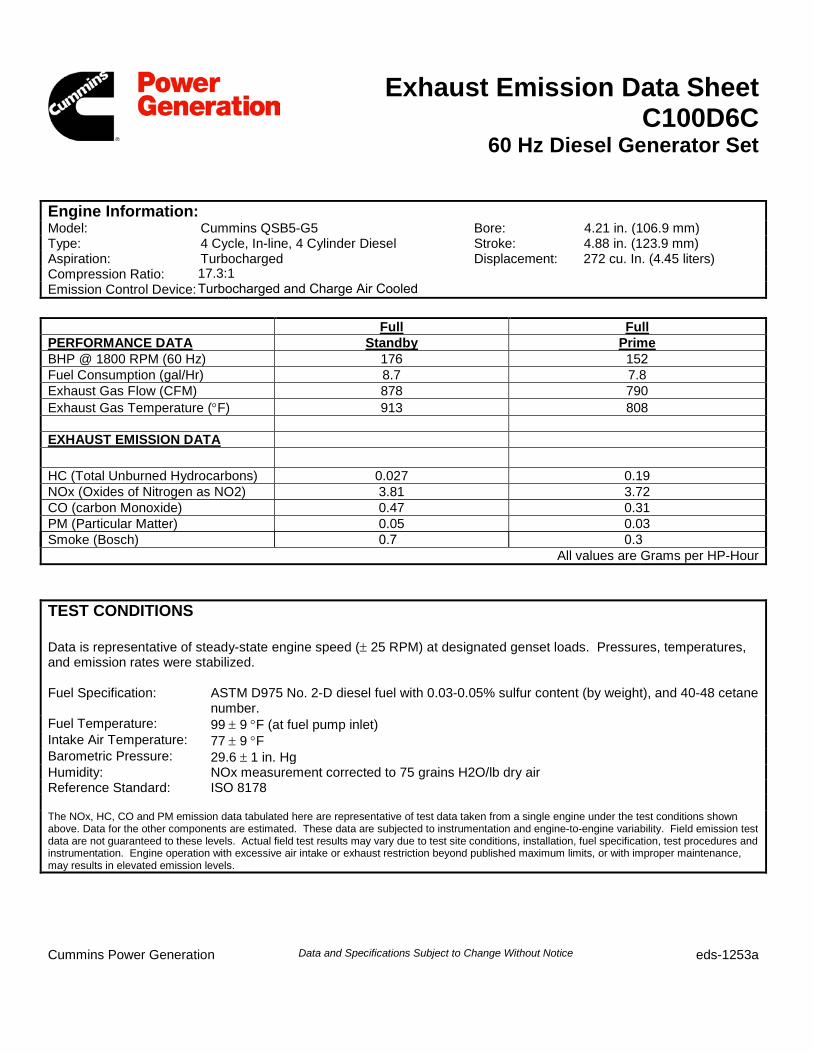
Exhaust Emission Data Sheet C100D6C
60 Hz Diesel Generator Set
Engine Information: Model: Cummins QSB5-G5 Bore: 4.21 in. (106.9 mm) Type: 4 Cycle, In-line, 4 Cylinder Diesel Aspiration: Turbocharged
Stroke: 4.88 in. (123.9 mm) Displacement: 272 cu. In. (4.45 liters)
Compression Ratio: Emission Control Device:
17.3:1 Turbocharged and Charge Air Cooled
Full Full PERFORMANCE DATA Standby Prime BHP @ 1800 RPM (60 Hz) 176 152 Fuel Consumption (gal/Hr) 8.7 7.8 Exhaust Gas Flow (CFM) 878 790 Exhaust Gas Temperature (°F) 913 808
EXHAUST EMISSION DATA
HC (Total Unburned Hydrocarbons) 0.027 0.19 NOx (Oxides of Nitrogen as NO2) 3.81 3.72 CO (carbon Monoxide) 0.47 0.31 PM (Particular Matter) 0.05 0.03 Smoke (Bosch) 0.7 0.3
All values are Grams per HP-Hour
TEST CONDITIONS
Data is representative of steady-state engine speed (± 25 RPM) at designated genset loads. Pressures, temperatures, and emission rates were stabilized.
Fuel Specification: ASTM D975 No. 2-D diesel fuel with 0.03-0.05% sulfur content (by weight), and 40-48 cetane number.
Fuel Temperature: 99 ± 9 °F (at fuel pump inlet) Intake Air Temperature: 77 ± 9 °F Barometric Pressure: 29.6 ± 1 in. Hg Humidity: NOx measurement corrected to 75 grains H2O/lb dry air Reference Standard: ISO 8178
The NOx, HC, CO and PM emission data tabulated here are representative of test data taken from a single engine under the test conditions shown above. Data for the other components are estimated. These data are subjected to instrumentation and engine-to-engine variability. Field emission test data are not guaranteed to these levels. Actual field test results may vary due to test site conditions, installation, fuel specification, test procedures and instrumentation. Engine operation with excessive air intake or exhaust restriction beyond published maximum limits, or with improper maintenance, may results in elevated emission levels.
Cummins Power Generation Data and Specifications Subject to Change Without Notice eds-1253a
Cummins Power Generation Data and Specifications Subject to Change Without Notice epa-1353a
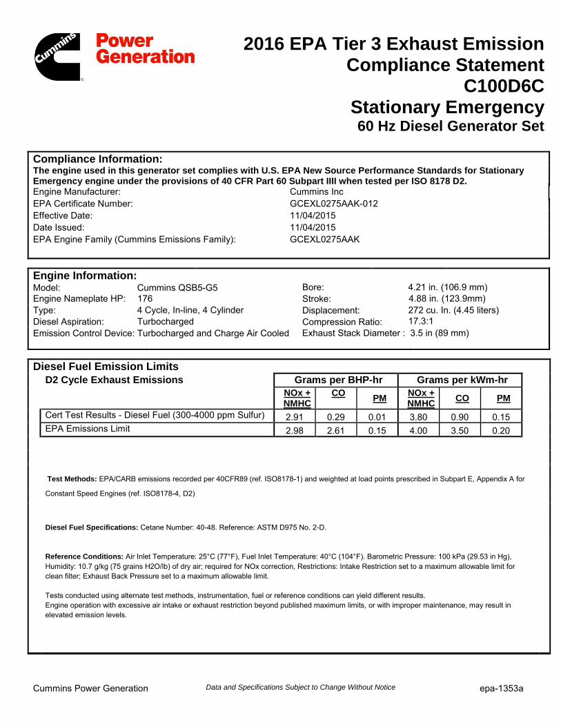
2016 EPA Tier 3 Exhaust Emission Compliance Statement
C100D6C Stationary Emergency 60 Hz Diesel Generator Set
Compliance Information: The engine used in this generator set complies with U.S. EPA New Source Performance Standards for Stationary Emergency engine under the provisions of 40 CFR Part 60 Subpart IIII when tested per ISO 8178 D2. Engine Manufacturer: Cummins Inc EPA Certificate Number: GCEXL0275AAK-012 Effective Date: 11/04/2015 Date Issued: 11/04/2015 EPA Engine Family (Cummins Emissions Family): GCEXL0275AAK
Diesel Fuel Emission Limits D2 Cycle Exhaust Emissions Grams per BHP-hr Grams per kWm-hr
NOx + NMHC
CO PM NOx + NMHC CO PM
Cert Test Results - Diesel Fuel (300-4000 ppm Sulfur) 2.91 0.29 0.01 3.80 0.90 0.15 EPA Emissions Limit 2.98 2.61 0.15 4.00 3.50 0.20
Test Methods: EPA/CARB emissions recorded per 40CFR89 (ref. ISO8178-1) and weighted at load points prescribed in Subpart E, Appendix A for
Constant Speed Engines (ref. ISO8178-4, D2)
Diesel Fuel Specifications: Cetane Number: 40-48. Reference: ASTM D975 No. 2-D.
Reference Conditions: Air Inlet Temperature: 25°C (77°F), Fuel Inlet Temperature: 40°C (104°F). Barometric Pressure: 100 kPa (29.53 in Hg), Humidity: 10.7 g/kg (75 grains H2O/lb) of dry air; required for NOx correction, Restrictions: Intake Restriction set to a maximum allowable limit for clean filter; Exhaust Back Pressure set to a maximum allowable limit.
Tests conducted using alternate test methods, instrumentation, fuel or reference conditions can yield different results. Engine operation with excessive air intake or exhaust restriction beyond published maximum limits, or with improper maintenance, may result in elevated emission levels.
Engine Information: Cummins QSB5-G5 Model:
Engine Nameplate HP: 176 4 Cycle, In-line, 4 Cylinder Type:
Diesel Aspiration: Turbocharged
4.21 in. (106.9 mm) Bore: Stroke: Displacement: Compression Ratio:
4.88 in. (123.9mm) 272 cu. In. (4.45 liters)
17.3:1 Exhaust Stack Diameter : 3.5 in (89 mm)Emission Control Device: Turbocharged and Charge Air Cooled
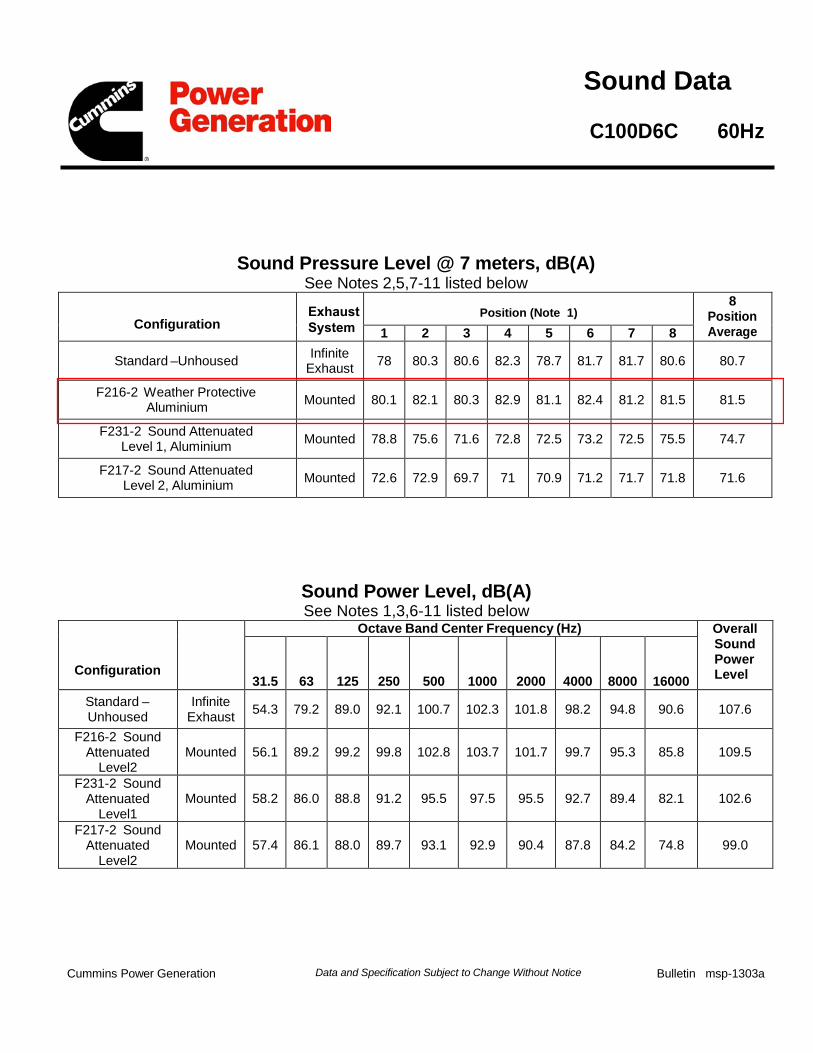
Cummins Power Generation Data and Specification Subject to Change Without Notice Bulletin msp-1303a
Sound Pressure Level @ 7 meters, dB(A) See Notes 2,5,7-11 listed below
Configuration Position (Note 1)
8 Position Average 1 2 3 4 5 6 7 8
Standard –Unhoused Infinite Exhaust 78 80.3 80.6 82.3 78.7 81.7 81.7 80.6 80.7
F216-2 Weather Protective Aluminium Mounted 80.1 82.1 80.3 82.9 81.1 82.4 81.2 81.5 81.5
F231-2 Sound Attenuated Level 1, Aluminium Mounted 78.8 75.6 71.6 72.8 72.5 73.2 72.5 75.5 74.7
F217-2 Sound Attenuated Level 2, Aluminium Mounted 72.6 72.9 69.7 71 70.9 71.2 71.7 71.8 71.6
Sound Power Level, dB(A) See Notes 1,3,6-11 listed below
Configuration
Octave Band Center Frequency (Hz) Overall Sound Power Level 31.5 63 125 250 500 1000 2000 4000 8000 16000
Standard – Unhoused
Infinite Exhaust 54.3 79.2 89.0 92.1 100.7 102.3 101.8 98.2 94.8 90.6 107.6
F216-2 Sound Attenuated
Level2 Mounted 56.1 89.2 99.2 99.8 102.8 103.7 101.7 99.7 95.3 85.8 109.5
F231-2 Sound Attenuated
Level1 Mounted 58.2 86.0 88.8 91.2 95.5 97.5 95.5 92.7 89.4 82.1 102.6
F217-2 Sound Attenuated
Level2 Mounted 57.4 86.1 88.0 89.7 93.1 92.9 90.4 87.8 84.2 74.8 99.0
Sound Data
C100D6C 60Hz
ExhaustSystem

Cummins Power Generation Data and Specification Subject to Change Without Notice Bulletin msp-1303a
.Exhaust Sound Power Level, dB(A)
See Notes 4,6 , 9 listed below
Open Exhaust (No Muffler) @ Rated Load
Octave Band Center Frequency (Hz) Overall Sound Power Level
31.5 63 125 250 500 1000 2000 4000 8000
57 84 99 105 112 113 116 116 113 122
Note: 1. Sound pressure levels at 1 meter are measured per the requirements of ISO 3744, ISO 8528-10, ANSI S1.13, ANSI S12.1 and European
Communities Directive 2000/14/EC as applicable. The microphone measurement locations are 1 meter from a reference parallelepiped just enclosing the generator set (enclosed or unenclosed).
2. Seven-meter measurement location 1 is 7 meters (23 feet) from the generator (alternator) end of the generator set, and the locations proceed counterclockwise around the generator set at 45° angles at a height of 1.2 meters (48 inches) above the ground surface.
3. Sound Power Levels are calculated according to ISO 3744, ISO 8528-10, and or CE (European Union) requirements. 4. Exhaust Sound Levels are measured and calculated per ISO 6798, Annex A. 5. Reference Sound Pressure Level is 20 µPa. 6. Reference Sound Power Level is 1 pW (10-12 Watt). 7. Sound data for remote-cooled generator sets are based on rated loads without cooling fan noise. 8. Sound data for the generator set with infinite exhaust do not include the exhaust noise contribution. 9. Sound levels are subject to instrumentation, measurement, installation, and manufacturing variability. 10. Unhoused/Open configuration generator sets refers to generator sets with no sound enclosures of any kind. 11. Housed/Enclosed/Closed/Canopy configuration generator sets refer to generator sets that have noise reduction sound enclosures
installed over the generator set and usually integrally attached to the skid base/base frame/fuel container base of the generator set.

PROTOTYPE TEST SUPPORT (PTS) 60 HZ TEST SUMMARY
GENERATOR SET MODELS REPRESENTATIVE PROTOTYPE
C50D6C C80D6C Model: C100D6C C60D6C C100D6C Engine: QSB5-G5
Alternator: UC27 D
The following summarizes prototype testing conducted on the designated representative prototype of the specified models. This testing is conducted to verify the complete generator set electrical and mechanical design integrity. Prototype testing is conducted only on generator sets not sold as new equipment.
Steady State Performance: Maximum Surge Power: 117.5 kW The generator set was evaluated to determine the stated maximum surge power.
The generator set was tested to verify if the steady state operating performance was within the specified maximum limits.
Voltage Regulation: ± 1% Random Voltage Variation: ± 1% Maximum Motor Starting: 146.3 kVA
The generator set was tested to simulate motor starting by applying the specified kVA load at low lagging power factor (0.4 or lower). With this load applied, the generator set recovered to a minimum of 90% rated voltage.
Frequency Regulation: ± Isochronous Random Frequency Variation: ± 0.5%
Transient Performance: The generator set was tested to verify single step loading capability as required by NFPA 110 and verify acceptable voltage and frequency response on load addition or rejection. The following results were recorded at 1.0 power factor :
Alternator Temperature Rise: The highest rated temperature rise ( 120°C ) test results are reported as follows to verify that worst case temperature rises do not exceed allowable NEMA MG1 limits for class H insulation. Tests were conducted per IEEE 115, rise by resistance and embedded detector, with the rated voltages. Only the highest temperatures are reported.
Full Load Acceptance: Voltage Dip: 28 % Recovery Time: 1.3 sec Frequency Dip: 9.1 %
Location: Maximum Rise (°C) Recovery Time: 2.6 sec Alternator Stator: NA Full Load Rejection: Alternator Rotor: NA Voltage Rise: 20.2 % Exciter Stator: NA Recovery Time: 0.6 sec Exciter Rotor: NA Frequency Rise: 7.0 %
Recovery Time: 1.7 sec Torsional Analysis and Testing: The generator set was tested to verify that the design is not Harmonic Analysis: subjected to harmful torsional stresses. (per MIL-STD-705B, Method 601.4) A spectrum analysis of the transducer output was conducted Line to Line Line to Neutral
Harmonic No Load Full Load No Load Full Load 3 0.04 0.15 0.15 0.15
Cooling System: 50 °C Ambient 5 0.2 0.2 0.2 0.2 0.5 in. H2O restriction 7 0.6 0.6 0.6 0.6
The cooling system was tested to determine ambient temperature and static restriction capabilities. The test was performed at full rated load in elevated ambient temperature under static restriction conditions.
9 0.02 0.04 0.04 0.04 11 0.52 0.52 0.52 0.52 13 0.26 0.26 0.26 0.26 15 0.0 0.0 0.0 0.0
Durability: Electrical and Mechanical Strength: The generator set was tested to several single phase and three phase faults to verify that the generator can safely withstand the forces associated with short circuit conditions. The generator set was capable of producing full rated output at the conclusion of the testing.
The C100D6C generator set was subjected to a minimum 500 hour endurance test operating at variable load up to the standby rating based upon MIL-STD-705 to verify structural soundness and durability of the design.
Cummins Power Generation Specification May Change Without Notice pts-450a

ALTERNATOR DATA SHEET Frame Size: UC3DCHARACTERISTICS
WEIGHTS:
EXCITATION CURRENT:INSULATION SYSTEM:
Wound Stator Assembly
Rotor Assembly
Complete Alternator
Full Load
Class H Throughout
Amps2
lb265
lb317
lb941
kg120
kg144
kg427
No Load Amps0.5
MAXIMUM SPEED: rpm2250
1 Ø RATINGS (1.0 power factor) 60 HzDouble Delta
120/240120/240
90 90
81 81
79 79
72 72
50 HzDouble Delta
110-120
68 68
60 60
(Based on specified temperature rise at 40°C ambient temperature)
125°C Rise Ratings
105°C Rise RatingskW/kVA
kW/kVA
3 Ø RATINGS (0.8 power factor)
277/480
110
138
105
131
96
120
124
155
117
146
105
131
220/380 254/440240/415
97
121
91
114
80
100
97
121
91
114
80
100
92
116
87
109
74
93
(Based on specified temperature rise at 40°C ambient temperature)
150°C Rise Ratings
125°C Rise Ratings
105°C Rise Ratings
kW
kVA
kW
kVA
kW
kVA
240/416
120/208 139/240
380-416
110
138
105
131
96
120
190-208
347/600
124
155
117
146
105
131
110/190 120/208 127/220
3 Ø REACTANCES (per unit, ±10%)
(Based on full load at 105°C Rise Rating)
2.53
0.21
0.14
0.17
0.10
2.08
0.17
0.12
0.14
0.08
2.11
0.18
0.13
0.14
0.08
1.77
0.15
0.11
0.11
0.07
1.46
0.12
0.09
0.09
0.06
2.00
0.16
0.12
0.14
0.08
1.82
0.16
0.12
0.14
0.08
Synchronous
Transient
Subtransient
Negative Sequence
Zero Sequence
3 Ø MOTOR STARTINGMaximum kVA
(90% Sustained Voltage)
360
423
360
423
360
423
244
306
0.030
0.010
0.030
0.010
0.030
0.010
0.030
0.010
TIME CONSTANTSTransient
Subtransient
Open circuit
DC
0.820
0.007
0.820
0.007
0.820
0.007
0.820
0.007
0.0900
1.2000
0.0680
1.2000
0.1250
1.2000
0.0900
1.2000
WINDINGSStator Resistance
Rotor Resistance
Number of Leads 12 12 6 12
(Shunt)
(PMG)
(Sec)
(@ 20°C )
(Line to Line, Ohms)
( Ohms)
80°C Rise Ratings kW
kVA80
100
88
110
72
90
72
90
67
84
80
100
88
110
ADS - 207D
Upper Broad Range LBR* Broad Range
/
/
347/600
/
/
/
/
* Lower broad range 110/190 thru 120/208, 220/380 thru 240/416.
4 Lead
220-240
Cummins Power Generation Specification May change WIthout Notice.

CERTIFICATE OF COMPLCERTIFICATE OF COMPLCERTIFICATE OF COMPLCERTIFICATE OF COMPLIANCEIANCEIANCEIANCE
SEISMIC DESIGN OF NONSTRUCTURAL COMPONENTS AND SYSTEMS
Page 1 of 3
102S-103387 Rev 1
Certification No.
VMA-51071-01C (Revision 02)
Expiration Date: 07/31/2018
Certification Parameters: The nonstructural products (mechanical and/or electrical components) listed on this certificate are CERTIFIED
1 FOR SEISMIC APPLICATIONS
in accordance with the following building code2 releases.
IBC 2012, 2015
The following model designations, options, and accessories are included in this certification. Reference report number 77789-1302 and 33817-1501 as issued by Dynamic Certification Laboratories for a complete list of certified models, included accessories/options, and certified installation methods.
CUMMINS POWER GENERATION 10kW – 125kW Diesel Generator Sets
The above referenced equipment is APPROVED for seismic application when properly installed
3, used as intended, and contains a Seismic
Certification Label referencing this Certificate of Compliance4. As limited by the tabulated values, below grade, grade, and roof-level installations,
installations in essential facilities, for life safety applications, and/or of equipment containing hazardous contents are permitted and included in this certification with an Equipment Importance Factor assigned as IP=1.5. The equipment is qualified by successful seismic shake table testing at the nationally recognized Dynamic Certification Laboratories under the review of the ISO Accredited Product Certification Agency, The VMC Group.
Test Datum
AC156
ISO 17025 Laboratory
Pre/Post-Shake Functionality
Tri-axial, 5% Damping SRS
AFLEX-H ≤ 3.200 g AFLEX-V ≤
ARIG-H ≤ 2.400 g ARIG-V ≤
ZPAH ≤ 2.160 g ZPAV ≤ 0.480 g
1.333 g
0.533 g
Certified Seismic Design Levels
Certified
IBC
Importance IP ≤ 1.5
Soil Classes A-E
Risk Categories I-IV
Design Categories A-F
SDS ≤ 2.000 g ⁷⁷⁷⁷ SDS ≤ 2.000 g ⁷⁷⁷⁷
z/h = 0.0 z/h ≤ 1.0
Horizontal
Design5 1.440 g��
��� �.���
��
�� � �
�
��
Certified Seismic Installation MethodsRigid mounting from unit base to rigid structure

CERTIFICATE OF COMPLCERTIFICATE OF COMPLCERTIFICATE OF COMPLCERTIFICATE OF COMPLIANCEIANCEIANCEIANCE
SEISMIC DESIGN OF NONSTRUCTURAL COMPONENTS AND SYSTEMS
Page 2 of 3
102S-103387 Rev 1
Certified Product Table:
Model Power Rating
RPM
Maximum Dimensions (in)
Max Weight with Enclosure
(lb)
Certified Fuel Tank Capacities
(gal)
SDS (g) z/h=1
Length Width Height
C10 D6 10 kW 1800 98 34 88 4,300 46, 74, 91,
132, 195, 263
2.0
C15 D6 15 kW 1800 98 34 88 4,400
C20 D6 20 kW 1800 98 34 88 4,470
C25 D6 25 kW 1800 131 34 88 5,890
74, 132, 195, 263, 389
C30 D6 30 kW 1800 131 34 88 5,930
C35 D6 35 kW 1800 131 34 88 5,960
C40 D6 40 kW 1800 131 34 88 6,140
C50 D6 50 kW 1800 131 34 88 6,260
C60 D6 60 kW 1800 131 34 88 6,260
C50 D6C 50 kW 1800 170 40 104 8,943
250, 425, 625 2.5
C60 D6C 60 kW 1800 170 40 104 8,990
C80 D6C 80 kW 1800 170 40 104 9,040
C100 D6C 100 kW 1800 170 40 104 9,216
C125 D6C 125 kW 1800 170 40 104 9,300 This certification includes the open generator set and the enclosed generator set when installed with or without the sub-base tank. This certification also includes the sub-base tank as a stand-alone accessory. The generator set and included options shall be a catalogue design and factory supplied. The generator set and applicable options shall be installed and attached to the building structure per the manufacturer supplied seismic installation instructions. This certification excludes all non-factory supplied accessories, including but not limited to mufflers, isolation/restraint devices, remote control panels, remote radiators, pumps and other electrical/mechanical components.
VMA-51071-01C (Revision 01) Issue Date: July 3, 2015
Revision Date: January 29, 2016 Expiration Date: July 31, 2018
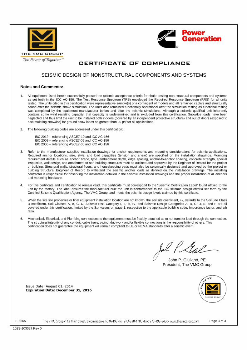
CERTIFICATE OF COMPLIANCE
SEISMIC DESIGN OF NONSTRUCTURAL COMPONENTS AND SYSTEMS
F-5665 Page 3 of 3
102S-103387 Rev 0
Notes and Comments:
1. All equipment listed herein successfully passed the seismic acceptance criteria for shake testing non-structural components and systemsas set forth in the ICC AC-156. The Test Response Spectrum (TRS) enveloped the Required Response Spectrum (RRS) for all unitstested. The units cited in this certification were representative sample(s) of a contingent of models and all remained captive and structurallysound after the seismic shake simulation. The units also remained functionally operational after the simulation testing as functional testingwas completed by the equipment manufacturer before and after the seismic simulations. Although a seismic qualified unit inherentlycontains some wind resisting capacity, that capacity is undetermined and is excluded from this certification. Snow/Ice loads have beenneglected and thus limit the unit to be installed both indoors (covered by an independent protective structure) and out of doors (exposed toaccumulating snow/ice) for ground snow loads no greater than 30 psf for all applications.
2. The following building codes are addressed under this certification:
IBC 2012 – referencing ASCE7-10 and ICC AC-156IBC 2009 – referencing ASCE7-05 and ICC AC-156IBC 2006 – referencing ASCE7-05 and ICC AC-156
3. Refer to the manufacturer supplied installation drawings for anchor requirements and mounting considerations for seismic applications.Required anchor locations, size, style, and load capacities (tension and shear) are specified on the installation drawings. Mountingrequirement details such as anchor brand, type, embedment depth, edge spacing, anchor-to-anchor spacing, concrete strength, specialinspection, wall design, and attachment to non-building structures must be outlined and approved by the Engineer of Record for the projector building. Structural walls, structural floors, and housekeeping pads must also be seismically designed and approved by the project orbuilding Structural Engineer of Record to withstand the seismic anchor loads as defined on the installation drawings. The installingcontractor is responsible for observing the installation detailed in the seismic installation drawings and the proper installation of all anchorsand mounting hardware.
4. For this certificate and certification to remain valid, this certificate must correspond to the “Seismic Certification Label” found affixed to theunit by the factory. The label ensures the manufacturer built the unit in conformance to the IBC seismic design criteria set forth by theCertified Seismic Qualification Agency, The VMC Group, and meets the seismic design levels claimed by this certificate.
5. When the site soil properties or final equipment installation location are not known, the soil site coefficient, FA, defaults to the Soil Site ClassD coefficient. Soil Classes A, B, C, D, Seismic Risk Category I, II, III, IV, and Seismic Design Categories A, B, C, D, E, and F are allcovered under this certification, limited by the SDS values on page 1, respective to the applicable building code, Importance factor, and z/hratio.
6. Mechanical, Electrical, and Plumbing connections to the equipment must be flexibly attached as to not transfer load through the connection.The structural integrity of any conduit, cable trays, piping, ductwork and/or flexible connections is the responsibility of others. Thiscertification does not guarantee the equipment will remain compliant to UL or NEMA standards after a seismic event.
John P. Giuliano, PEPresident, The VMC Group
Issue Date: August 01, 2014Expiration Date: December 31, 2016
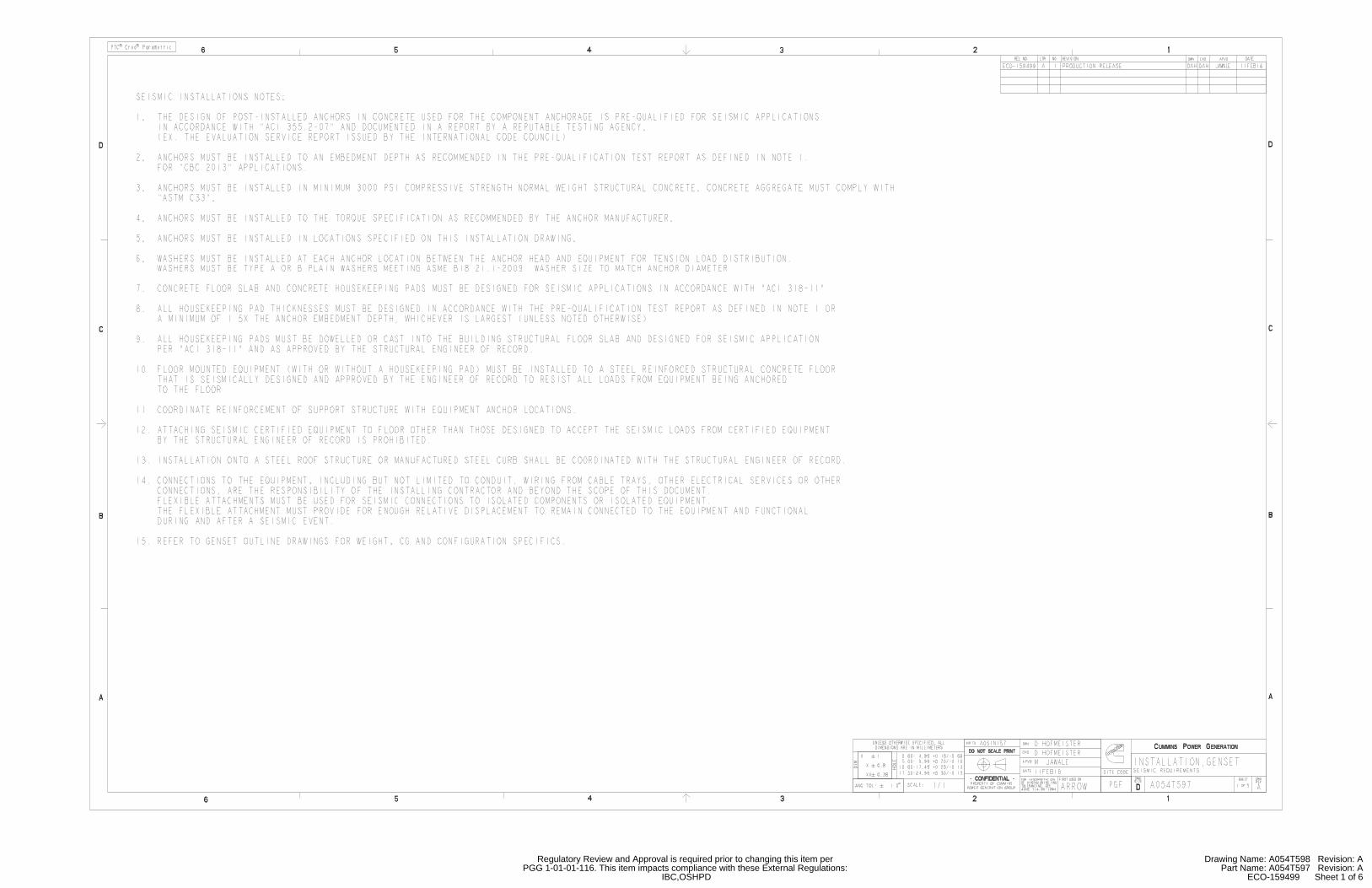
IBC,OSHPDPGG 1-01-01-116. This item impacts compliance with these External Regulations:
Regulatory Review and Approval is required prior to changing this item per
ECO-159499 Sheet 1 of 6Part Name: A054T597 Revision: A
Drawing Name: A054T598 Revision: A
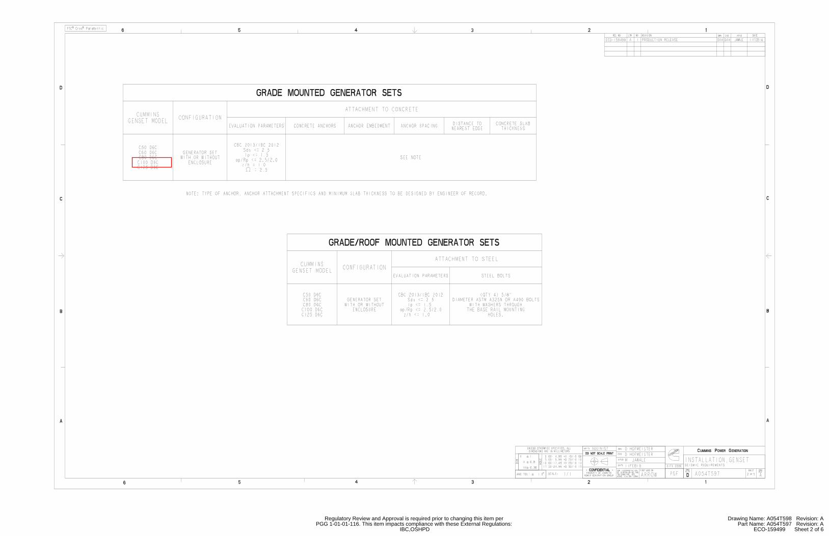
IBC,OSHPDPGG 1-01-01-116. This item impacts compliance with these External Regulations:
Regulatory Review and Approval is required prior to changing this item per
ECO-159499 Sheet 2 of 6Part Name: A054T597 Revision: A
Drawing Name: A054T598 Revision: A

IBC,OSHPDPGG 1-01-01-116. This item impacts compliance with these External Regulations:
Regulatory Review and Approval is required prior to changing this item per
ECO-159499 Sheet 3 of 6Part Name: A054T597 Revision: A
Drawing Name: A054T598 Revision: A

IBC,OSHPDPGG 1-01-01-116. This item impacts compliance with these External Regulations:
Regulatory Review and Approval is required prior to changing this item per
ECO-159499 Sheet 4 of 6Part Name: A054T597 Revision: A
Drawing Name: A054T598 Revision: A

IBC,OSHPDPGG 1-01-01-116. This item impacts compliance with these External Regulations:
Regulatory Review and Approval is required prior to changing this item per
ECO-159499 Sheet 5 of 6Part Name: A054T597 Revision: A
Drawing Name: A054T598 Revision: A

Sheet 1 of 2Part Name: A051P453 Revision: A
Drawing Name: A051P454 Revision: A

Sheet 1 of 5Part Name: A054B564 Revision: A
Drawing Name: A054B565 Revision: A

Sheet 2 of 5Part Name: A054B564 Revision: A
Drawing Name: A054B565 Revision: A
Normal vent only
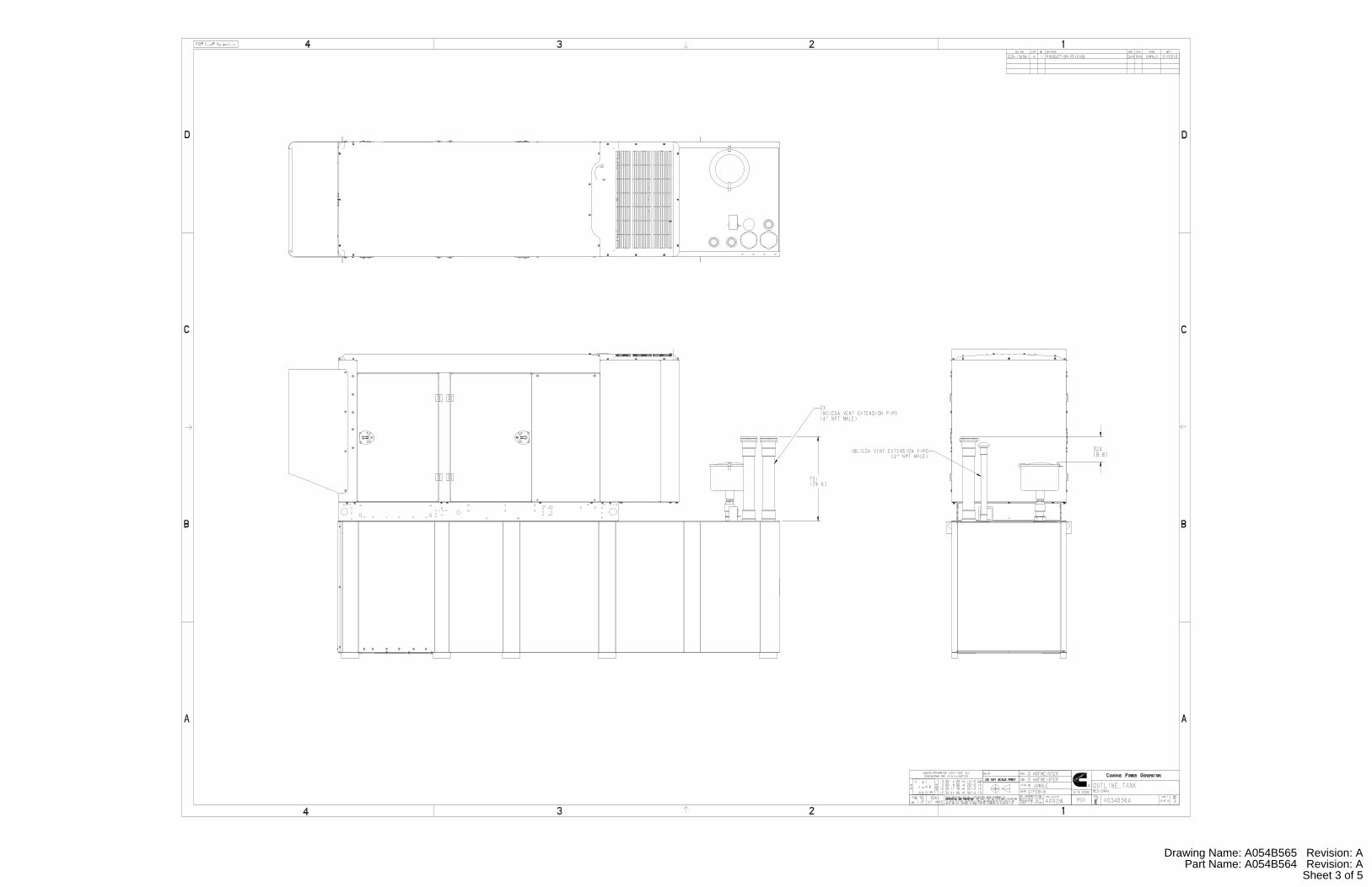
Sheet 3 of 5Part Name: A054B564 Revision: A
Drawing Name: A054B565 Revision: A

Sheet 4 of 5Part Name: A054B564 Revision: A
Drawing Name: A054B565 Revision: A

Our energy working for you.™ power.cummins.com ©2016 Cummins Power Generation Inc. | NAS-6236-EN (10/16)
Data sheet
Circuit breakers
Description
This data sheet provides circuit breaker manufacturer part numbers and specifications. Please refer to their website for more technical information.
Applicable models
Engine Models
Kubota C10D6 C15D6 C20D6
QSJ2.4 C20N6 C25N6 C30N6 C30N6H C36N6 C36N6H
C40N6 C40N6H C45N6H C50N6H C60N6H
B3.3 C25D6 C30D6 C35D6 C40D6 C50D6 C60D6
QSJ5.9G C45N6 C50N6 C60N6 C70N6 C80N6 C100N6
QSB5 DSFAC DSFAD DSFAE C50D6C C60D6C C80D6C
C100D6C C125D6C
QSB7 DSGAA DSGAB DSGAC DSGAD DSGAE
QSL9 DSHAD DQDAA DQDAB DQDAC
QSM11 DQHAB
QSX15 DFEJ DFEK
Instructions
1. Locate the circuit breaker feature code or part number and use the charts below to find the
corresponding manufacturer circuit breaker catalog number.
2. Use the first letter of the circuit breaker catalog number to determine the "frame" of the breaker. If
the first letter is an “N”, use the second letter. Then follow the corresponding website link from the
table below to find the breaker catalog number description.
Please refer to the catalog numbering systems page, which is given in the chart, to understand the
nomenclature of the catalog number.
Frame Catalog name* Catalog number
description page(s)
P 0612CT0101 16-17
H, J, and L 0611CT1001 8-9
Q 0734CT0201 4
*The following link may also be used to search specifically by the breaker part number or for the catalog name listed
above. http://products.schneider-electric.us/technical-library/

Our energy working for you.™ power.cummins.com ©2016 Cummins Power Generation Inc. | NAS-6236-EN (10/16)
3. Search the catalog by using the first 3 letters of the breaker catalog number and the first 5 numbers to find information
such as trip curves, accessories, and dimensional details regarding the circuit breaker.
*If the catalog number starts with “N”, skip the N and begin your search with the second letter.
*If the first 3 letters are “PJP,” the search will not work. You will need to start with just “PJ” and use the description pages to obtain the
information you are looking for on the “PJP.”
Example
After finding your circuit breaker catalog number to be "PJL36120U33EACUKMOYB," navigate to the P-frame catalog by using the link provided.
Look at pages 16-17 of the pdf catalog to find the nomenclature of the breaker.
Search the P-frame spec sheet using the search
"PJL36120.”

Our energy working for you.™ power.cummins.com ©2016 Cummins Power Generation Inc. | NAS-6236-EN (10/16)
Feature
Code
Breaker Description Cummins Part
#
Manufacturer Breaker Catalog
Number
Trip Unit Plug
Type
KX27-2 CB,Loc B,70A-250A,3P,LSI,600VAC,80%,UL A050J727 Schneider
Electric
JDL36250CU33X MicroLogic 3.3S N/A
KX28-2 CB,Loc B,70A-250A,3P,LSI,600VAC,100%,UL A050J727 Schneider
Electric
JDL36250CU33X MicroLogic 3.3S N/A
KX29-2 CB,Loc C,70A-250A,3P,LSI,600VAC,100%,UL A050J727 Schneider
Electric
JDL36250CU33X MicroLogic 3.3S N/A
KX30-2 CB,Loc A,125A-400A,3P,LSI,600VAC,100%,UL A051D115 Schneider
Electric
LGL36400CU33X MicroLogic 3.3S N/A
KX31-2 CB,Loc B,125A-400A,3P,LSI,600VAC,100%,UL A051D115 Schneider
Electric
LGL36400CU33X MicroLogic 3.3S N/A
KX32-2 CB,Loc A,200A-600A,3P,LSI,600VAC,80%,UL A044T468 Schneider
Electric
NLGL36600U33X-600A MicroLogic 3.3S N/A
KX33-2 CB,Loc B,200A-600A,3P,LSI,600VAC,80%,UL A044T468 Schneider
Electric
NLGL36600U33X-600A MicroLogic 3.3S N/A
KX34-2 CB,Loc C,15A,3P,600VAC,80%,UL A043L506 Schneider
Electric
HDL36015 Thermal
Magnetic
N/A
KX35-2 CB,Loc C,20A,3P,600VAC,80%,UL A043L480 Schneider
Electric
HDL36020 Thermal
Magnetic
N/A
KX36-2 CB,Loc C,25A,3P,600VAC,80%,UL A043L508 Schneider
Electric
HDL36025 Thermal
Magnetic
N/A
KX37-2 CB,LoC C,30A,3P,600VAC,80%,UL A043L475 Schneider
Electric
HDL36030 Thermal
Magnetic
N/A
KX38-2 CB,Loc C,40A,3P,600VAC,80%,UL A043L464 Schneider
Electric
HDL36040 Thermal
Magnetic
N/A
KX39-2 CB,Loc C,50A,3P,600VAC,80%,UL A043L461 Schneider
Electric
HDL36050 Thermal
Magnetic
N/A
KX40-2 CB,Loc C,60A,3P,600VAC,80%,UL A043L459 Schneider
Electric
HDL36060 Thermal
Magnetic
N/A
KX41-2 CB,Loc C,70A,3P,600VAC,80%,UL A043L451 Schneider
Electric
HDL36070 Thermal
Magnetic
N/A
KX42-2 CB,Loc C,80A,3P,600VAC,80%,UL A043L012 Schneider
Electric
HDL36080 Thermal
Magnetic
N/A
50 ampere breaker will be changed at site to a 50 ampere LSI breaker
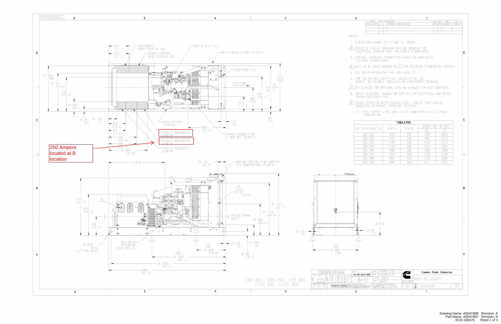
ECO-160476 Sheet 1 of 3Part Name: A054Y897 Revision: A
Drawing Name: A054Y898 Revision: A
250 Ampere located at B location
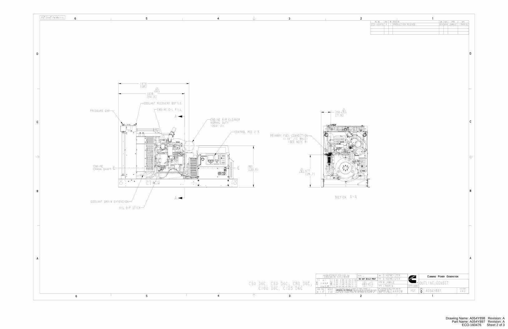
ECO-160476 Sheet 2 of 3Part Name: A054Y897 Revision: A
Drawing Name: A054Y898 Revision: A
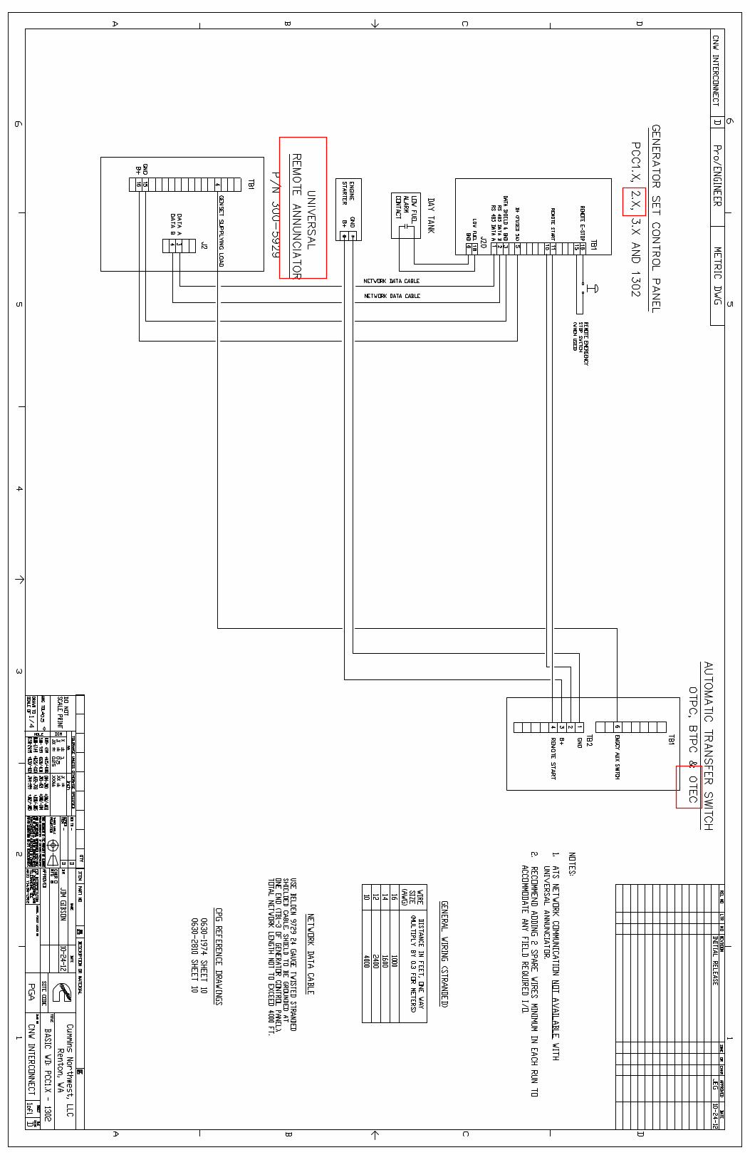
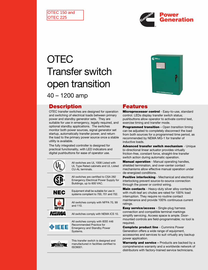
OTEC Transfer switch open transition 40 – 1200 amp
Description OTEC transfer switches are designed for operation and switching of electrical loads between primary power and standby generator sets. They are suitable for use in emergency, legally required, and optional standby applications. The switches monitor both power sources, signal generator set startup, automatically transfer power, and return the load to the primary power source once a stable utility is available.
The fully integrated controller is designed for practical functionality, with LED indicators and digital pushbuttons for ease of operator use.
Features Microprocessor control - Easy-to-use, standard control. LEDs display transfer switch status; pushbuttons allow operator to activate control test, exercise timing and transfer mode.
Programmed transition – Open transition timing can be adjusted to completely disconnect the load from both sources for a programmed time period, as recommended by NEMA MG-1 for transfer of inductive loads.
Advanced transfer switch mechanism - Unique bi-directional linear actuator provides virtually friction-free, constant force, straight-line transfer switch action during automatic operation.
Manual operation - Manual operating handles, shielded termination, and over-center contact mechanisms allow effective manual operation under de-energized conditions.
Positive interlocking - Mechanical and electrical interlocking prevent source-to-source connection through the power or control wiring.
Main contacts - Heavy-duty silver alloy contacts with multi-leaf arc chutes are rated for 100% load interruption. They require no routine contact maintenance and provide 100% continuous current ratings.
Easy service/access - Single-plug harness connection and compatible terminal markings simplify servicing. Access space is ample. Door-mounted controls are field-programmable; no tool is required.
Complete product line - Cummins Power Generation offers a wide range of equipment, accessories and services to suit virtually any backup power application.
Warranty and service - Products are backed by a comprehensive warranty and a worldwide network of distributors with factory-trained service technicians.
All switches are UL 1008 Listed with UL Type Rated cabinets and UL Listed CU-AL terminals.
All switches are certified to CSA 282 Emergency Electrical Power Supply for Buildings, up to 600 VAC.
NEC Equipment shall be suitable for use in systems compliant to 700, 701 and 702.
All switches comply with NFPA 70, 99 and 110.
All switches comply with NEMA ICS 10.
All switches comply with IEEE 446 Recommended Practice for Emergency and Standby Power Systems.
This transfer switch is designed and manufactured in facilities certified to ISO9001.
OTEC 150 and OTEC 225
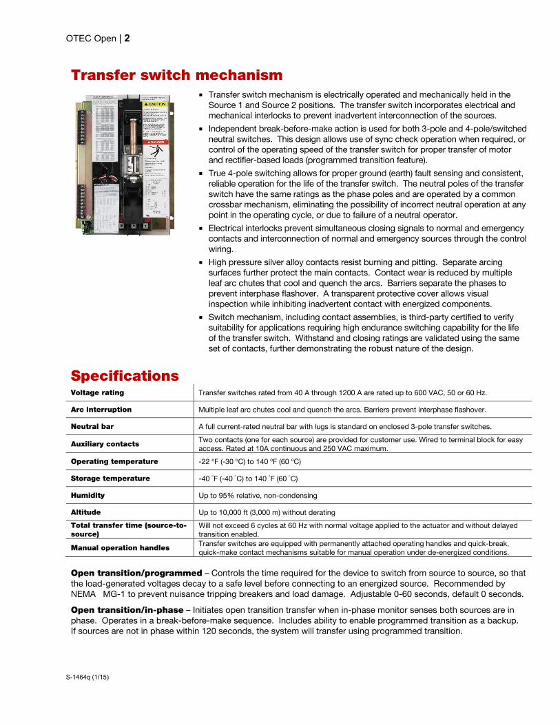
OTEC Open | 2
S-1464q (1/15)
Transfer switch mechanism
Transfer switch mechanism is electrically operated and mechanically held in the Source 1 and Source 2 positions. The transfer switch incorporates electrical and mechanical interlocks to prevent inadvertent interconnection of the sources.
Independent break-before-make action is used for both 3-pole and 4-pole/switched neutral switches. This design allows use of sync check operation when required, or control of the operating speed of the transfer switch for proper transfer of motor and rectifier-based loads (programmed transition feature).
True 4-pole switching allows for proper ground (earth) fault sensing and consistent, reliable operation for the life of the transfer switch. The neutral poles of the transfer switch have the same ratings as the phase poles and are operated by a common crossbar mechanism, eliminating the possibility of incorrect neutral operation at any point in the operating cycle, or due to failure of a neutral operator.
Electrical interlocks prevent simultaneous closing signals to normal and emergency contacts and interconnection of normal and emergency sources through the control wiring.
High pressure silver alloy contacts resist burning and pitting. Separate arcing surfaces further protect the main contacts. Contact wear is reduced by multiple leaf arc chutes that cool and quench the arcs. Barriers separate the phases to prevent interphase flashover. A transparent protective cover allows visual inspection while inhibiting inadvertent contact with energized components.
Switch mechanism, including contact assemblies, is third-party certified to verify suitability for applications requiring high endurance switching capability for the life of the transfer switch. Withstand and closing ratings are validated using the same set of contacts, further demonstrating the robust nature of the design.
Specifications
Voltage rating Transfer switches rated from 40 A through 1200 A are rated up to 600 VAC, 50 or 60 Hz.
Arc interruption Multiple leaf arc chutes cool and quench the arcs. Barriers prevent interphase flashover.
Neutral bar A full current-rated neutral bar with lugs is standard on enclosed 3-pole transfer switches.
Auxiliary contacts Two contacts (one for each source) are provided for customer use. Wired to terminal block for easy access. Rated at 10A continuous and 250 VAC maximum.
Operating temperature -22 oF (-30 oC) to 140 oF (60 oC)
Storage temperature -40 F (-40 C) to 140 F (60 C)
Humidity Up to 95% relative, non-condensing
Altitude Up to 10,000 ft (3,000 m) without derating
Total transfer time (source-to-source)
Will not exceed 6 cycles at 60 Hz with normal voltage applied to the actuator and without delayed transition enabled.
Manual operation handles Transfer switches are equipped with permanently attached operating handles and quick-break, quick-make contact mechanisms suitable for manual operation under de-energized conditions.
Open transition/programmed – Controls the time required for the device to switch from source to source, so that the load-generated voltages decay to a safe level before connecting to an energized source. Recommended by NEMA MG-1 to prevent nuisance tripping breakers and load damage. Adjustable 0-60 seconds, default 0 seconds.
Open transition/in-phase – Initiates open transition transfer when in-phase monitor senses both sources are in phase. Operates in a break-before-make sequence. Includes ability to enable programmed transition as a backup. If sources are not in phase within 120 seconds, the system will transfer using programmed transition.
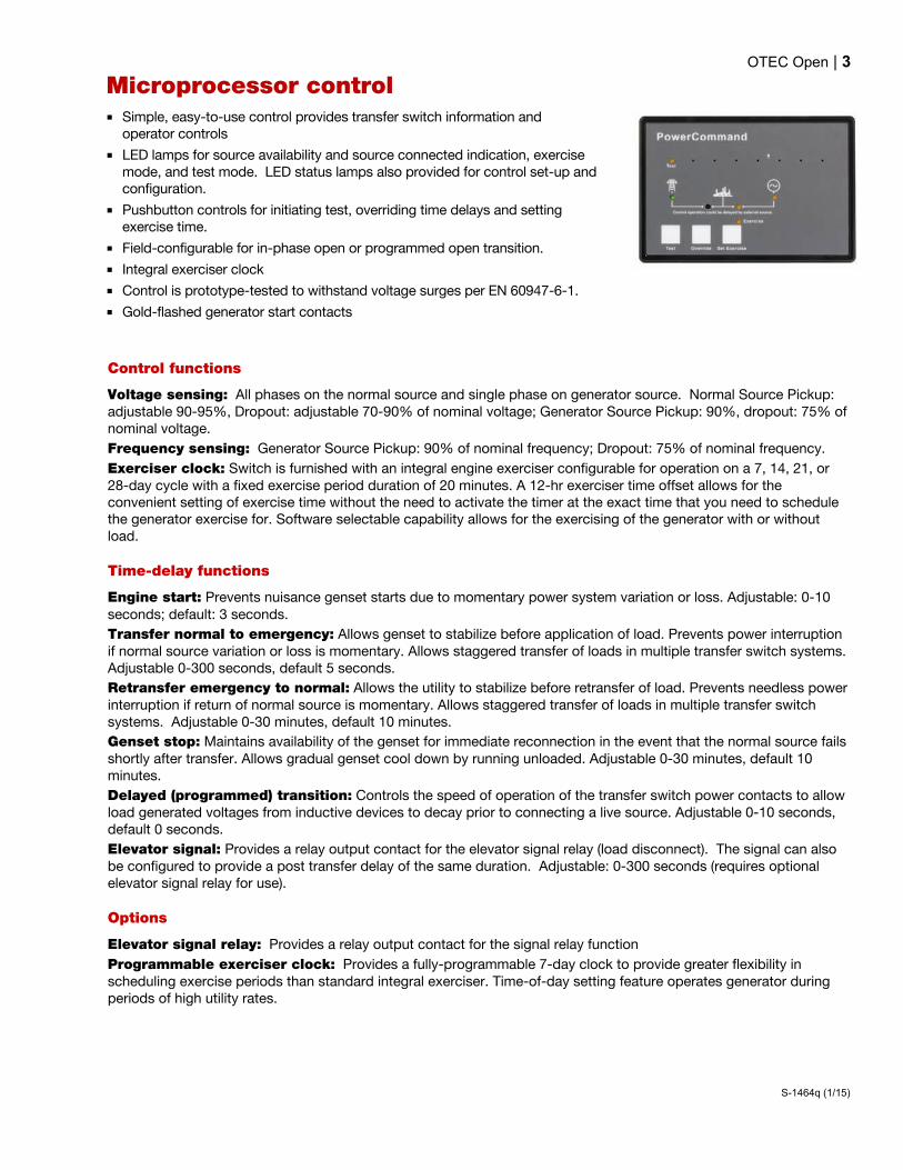
OTEC Open | 3
S-1464q (1/15)
Microprocessor control Simple, easy-to-use control provides transfer switch information and
operator controls
LED lamps for source availability and source connected indication, exercise mode, and test mode. LED status lamps also provided for control set-up and configuration.
Pushbutton controls for initiating test, overriding time delays and setting exercise time.
Field-configurable for in-phase open or programmed open transition.
Integral exerciser clock
Control is prototype-tested to withstand voltage surges per EN 60947-6-1.
Gold-flashed generator start contacts
Control functions
Voltage sensing: All phases on the normal source and single phase on generator source. Normal Source Pickup: adjustable 90-95%, Dropout: adjustable 70-90% of nominal voltage; Generator Source Pickup: 90%, dropout: 75% of nominal voltage.
Frequency sensing: Generator Source Pickup: 90% of nominal frequency; Dropout: 75% of nominal frequency.
Exerciser clock: Switch is furnished with an integral engine exerciser configurable for operation on a 7, 14, 21, or 28-day cycle with a fixed exercise period duration of 20 minutes. A 12-hr exerciser time offset allows for the convenient setting of exercise time without the need to activate the timer at the exact time that you need to schedule the generator exercise for. Software selectable capability allows for the exercising of the generator with or without load.
Time-delay functions
Engine start: Prevents nuisance genset starts due to momentary power system variation or loss. Adjustable: 0-10 seconds; default: 3 seconds.
Transfer normal to emergency: Allows genset to stabilize before application of load. Prevents power interruption if normal source variation or loss is momentary. Allows staggered transfer of loads in multiple transfer switch systems. Adjustable 0-300 seconds, default 5 seconds.
Retransfer emergency to normal: Allows the utility to stabilize before retransfer of load. Prevents needless power interruption if return of normal source is momentary. Allows staggered transfer of loads in multiple transfer switch systems. Adjustable 0-30 minutes, default 10 minutes.
Genset stop: Maintains availability of the genset for immediate reconnection in the event that the normal source fails shortly after transfer. Allows gradual genset cool down by running unloaded. Adjustable 0-30 minutes, default 10 minutes.
Delayed (programmed) transition: Controls the speed of operation of the transfer switch power contacts to allow load generated voltages from inductive devices to decay prior to connecting a live source. Adjustable 0-10 seconds, default 0 seconds.
Elevator signal: Provides a relay output contact for the elevator signal relay (load disconnect). The signal can also be configured to provide a post transfer delay of the same duration. Adjustable: 0-300 seconds (requires optional elevator signal relay for use).
Options
Elevator signal relay: Provides a relay output contact for the signal relay function
Programmable exerciser clock: Provides a fully-programmable 7-day clock to provide greater flexibility in scheduling exercise periods than standard integral exerciser. Time-of-day setting feature operates generator during periods of high utility rates.

OTEC Open | 4
S-1464q (1/15)
UL withstand and closing ratings The transfer switches listed below must be protected by circuit breakers or fuses. Referenced drawings include detailed listings of specific breakers or fuse types that must be used with the respective transfer switches. Consult with your distributor/dealer to obtain the necessary drawings. Withstand and Closing Ratings (WCR) are stated in symmetrical RMS amperes.
Transfer switch ampere
MCCB protection Special circuit breaker protection
WCR @ volts max with specific manufacturers MCCBs
Max MCCB ratings
Drawing reference
With specific current limiting breakers (CLB)
Max CLB rating Drawing reference
40, 70, 125 3-pole
14,000 at 600 225 A A050J441 200,000 @ 600 225 A A048J566
40, 70, 125 4-pole
30,000 at 600 225 A A050J441 200,000 @ 600 225 A A048J566
150, 225, 260 30,000 at 600 400 A A048E949 200,000 @ 600 400 A A051D533
300, 400, 600 65,000 at 600 1200 A A048E951 200,000 @ 600 1200 A A048J564
800, 1000 65,000 @ 480
1400 A A048E953 200,000 @ 600 1400 A A048J562 50,000 @ 600
1200 85,000 @ 480
1600 A A048E947 200,000 @ 600 1600 A A048P186 65,000 @ 600
Fuse protection
Transfer switch ampere
WCR @ volts max. with current limiting fuses Max fuse, size and type Drawing reference
40, 70, 125 3- and 4-pole
200,000 at 600 200 A Class, J, RK1, RK5, T A050J441
150, 225, 260 200,000 at 600 1200 A Class L or T, or 600 A class J, RK1, RK5 A048E949
300, 400, 600 200,000 at 600 1200 A Class L or T, or 600 A Class, J, RK1, RK5 A048E951
800, 1000 200,000 at 600 2000 A Class L or 1200 A class T or 600 A class J, RK1, RK5 A048E953
1200 200,000 at 600 2000 A Class L or 1200 A class T or 600 A class J, RK1, RK5 A048E947
3-cycle ratings
Transfer switch ampere
WCR @ volts max 3-cycle rating Max MCCB rating Drawing reference
1200 42,000 at 600
1600 A A048E947 50,000 at 480
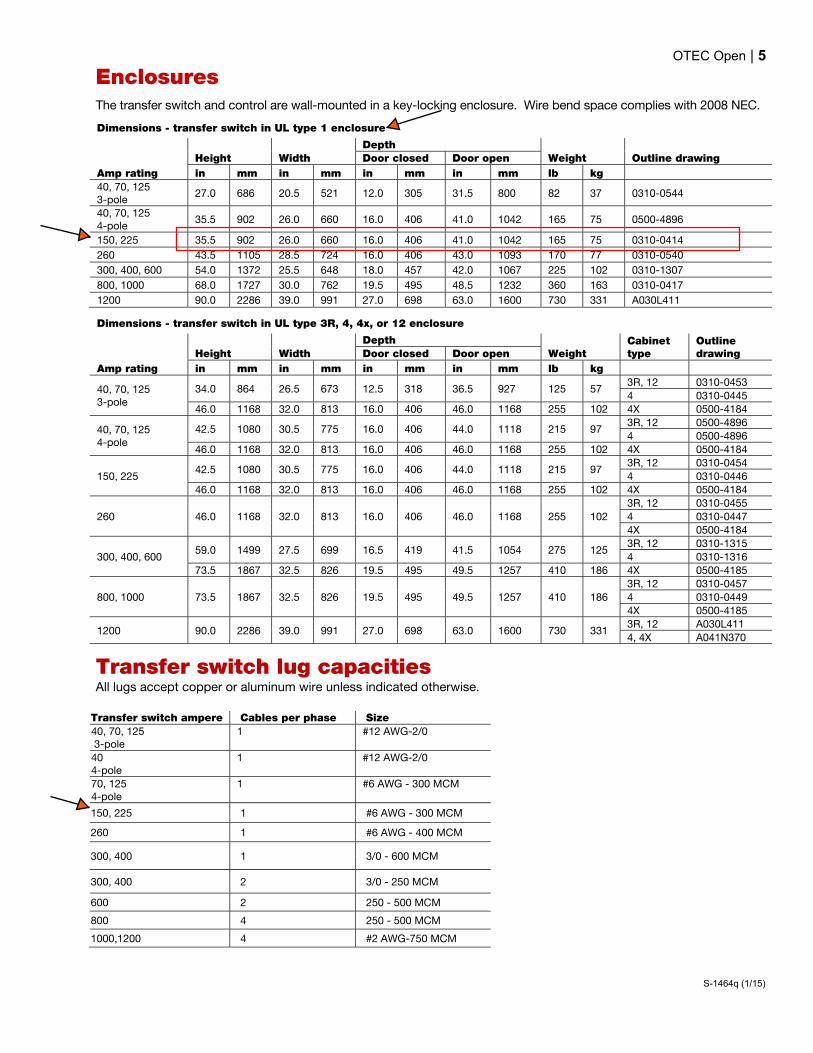
OTEC Open | 5
S-1464q (1/15)
Enclosures The transfer switch and control are wall-mounted in a key-locking enclosure. Wire bend space complies with 2008 NEC.
Dimensions - transfer switch in UL type 1 enclosure
Amp rating
Height Width
Depth
Weight Outline drawing Door closed Door open
in mm in mm in mm in mm lb kg
40, 70, 125 3-pole
27.0 686 20.5 521 12.0 305 31.5 800 82 37 0310-0544
40, 70, 125 4-pole
35.5 902 26.0 660 16.0 406 41.0 1042 165 75 0500-4896
150, 225 35.5 902 26.0 660 16.0 406 41.0 1042 165 75 0310-0414
260 43.5 1105 28.5 724 16.0 406 43.0 1093 170 77 0310-0540
300, 400, 600 54.0 1372 25.5 648 18.0 457 42.0 1067 225 102 0310-1307
800, 1000 68.0 1727 30.0 762 19.5 495 48.5 1232 360 163 0310-0417
1200 90.0 2286 39.0 991 27.0 698 63.0 1600 730 331 A030L411
Dimensions - transfer switch in UL type 3R, 4, 4x, or 12 enclosure
Amp rating
Height Width
Depth
Weight Cabinet type
Outline drawing Door closed Door open
in mm in mm in mm in mm lb kg
40, 70, 125 3-pole
34.0 864 26.5 673 12.5 318 36.5 927 125 57 3R, 12 0310-0453
4 0310-0445
46.0 1168 32.0 813 16.0 406 46.0 1168 255 102 4X 0500-4184
40, 70, 125 4-pole
42.5 1080 30.5 775 16.0 406 44.0 1118 215 97 3R, 12 0500-4896
4 0500-4896
46.0 1168 32.0 813 16.0 406 46.0 1168 255 102 4X 0500-4184
150, 225 42.5 1080 30.5 775 16.0 406 44.0 1118 215 97
3R, 12 0310-0454
4 0310-0446
46.0 1168 32.0 813 16.0 406 46.0 1168 255 102 4X 0500-4184
260 46.0 1168 32.0 813 16.0 406 46.0 1168 255 102
3R, 12 0310-0455
4 0310-0447
4X 0500-4184
300, 400, 600 59.0 1499 27.5 699 16.5 419 41.5 1054 275 125
3R, 12 0310-1315
4 0310-1316
73.5 1867 32.5 826 19.5 495 49.5 1257 410 186 4X 0500-4185
800, 1000 73.5 1867 32.5 826 19.5 495 49.5 1257 410 186
3R, 12 0310-0457
4 0310-0449
4X 0500-4185
1200 90.0 2286 39.0 991 27.0 698 63.0 1600 730 331 3R, 12 A030L411
4, 4X A041N370
Transfer switch lug capacities All lugs accept copper or aluminum wire unless indicated otherwise.
Transfer switch ampere Cables per phase Size
40, 70, 125 3-pole
1 #12 AWG-2/0
40 4-pole
1 #12 AWG-2/0
70, 125 4-pole
1 #6 AWG - 300 MCM
150, 225 1 #6 AWG - 300 MCM
260 1 #6 AWG - 400 MCM
300, 400 1 3/0 - 600 MCM
300, 400 2 3/0 - 250 MCM
600 2 250 - 500 MCM
800 4 250 - 500 MCM
1000,1200 4 #2 AWG-750 MCM

OTEC Open | 6
S-1464q (1/15)
Submittal detail
Amperage ratings 40 70 125 150 225 260 300 400 600 800 1000 1200
Voltage ratings R020 120 R038 190 R021 208 R022 220 R023 240 R024 380 R025 416 R035 440 R026 480 R027 600
Pole configuration A028 Poles - 3 (solid neutral) A029 Poles - 4 (switched neutral)
Frequency A044 60 Hertz A045 50 Hertz
Application A035 Utility to genset
System Options A041 Single phase, 2-wire or 3-wire A042 Three phase, 3-wire or 4-wire
Enclosure B001 Type 1: general purpose indoor (similar to IEC
Type IP30) B002 Type 3R: intended for outdoor use, provides some
protection from dirt, rain and snow (similar to IEC Type IP34)
B003 Type 4: indoor or outdoor use, provides some protection from wind-blown dust and water spray (similar to IEC Type IP65)
B010 Type 12: indoor use, some protection from dust (similar to IEC Type IP61)
B025 Type 4X: stainless steel, indoor or outdoor use, provides some protection from corrosion (similar to IEC Type IP65)
Standards A046 UL 1008/CSA certification A080 Seismic certification
Control voltage M033 12V, Genset starting voltage M034 24V, Genset starting voltage
Control options J030 External exercise clock M032 Elevator signal relay
Battery chargers K001 2 Amps, 12/24 Volts KB59 15 Amps, 12 Volts KB60 12 Amps, 24 Volts
Auxiliary relays Relays are UL Listed and factory installed. All relays provide (2) normally closed isolated contacts rated 10A @ 600 VAC. Relay terminals accept (1) 18 gauge to (2) 12 gauge wires per terminal. L101 24 VDC coil - installed, not wired (for customer
use). L102 24 VDC coil - emergency position - relay
energized when switch is in source 2 (emergency) position.
L103 24 VDC coil - normal position - relay energized when switch is in source 1 (normal) position
L201 12 VDC coil installed, not wired (for customer use) L202 12 VDC coil - emergency position - relay
energized when switch is in source 2 (emergency) position
L203 12 VDC coil - normal position - relay energized when switch is in source 1 (normal) position
Miscellaneous options C027 Cover - guard M003 Terminal block - 30 points (not wired)
Optional lug kits N032 Lug adapters, compression, ½ stab (1200A only) N045 Cable lugs, mechanical, 600 MCM, 4 per pole
(1200A only) N066 Cable lugs, mechanical, 750 MCM, 4 per pole
(1200A only)
Warranty G009 1 year comprehensive G004 2 year comprehensive G006 5 year basic G007 5 year comprehensive G008 10 year major components
Shipping A051 Packing – export box (800-1000 A)
Accessories AC-170 Accessories specifications sheet
see Material Summary for selected options
OTEC Open | 7
S-1464q (1/15)
North America 1400 73rd Avenue N.E. Minneapolis, MN 55432 USA Phone 763 574 5000 Fax 763 574 5298 Asia Pacific 10 Toh Guan Road #07-01 TT International Tradepark Singapore 608838 Phone 65 6417 2388 Fax 65 6417 2399 Brazil Rua Jati, 310 Guarulhos – Sao Paulo CEP – 07180-140 Phone 55 11 2186 4195 Fax 55 11 2186 4729 Europe, CIS, Middle East & Africa Manston Park Columbus Ave. Manston Ramsgate Kent CT 12 5BF United Kingdom Phone 44 1843 255000 Fax 44 1843 255902
www.cumminspower.com
Specifications are subject to change without notice. ©2015 Cummins Power Generation. All rights reserved. Cummins Power Generation and Cummins are registered trademarks of Cummins Inc. PowerCommand, InPower and “Our energy working for you.” are trademarks of Cummins Power Generation.

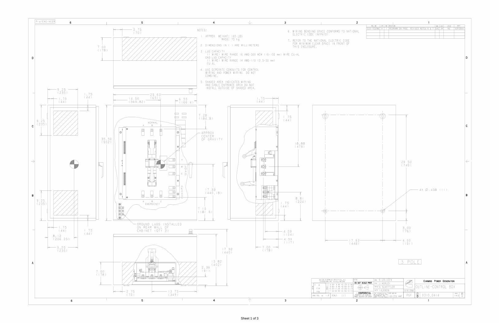
Sheet 1 of 3

Sheet 1 of 5

Sheet 2 of 5

Sheet 3 of 5

Sheet 4 of 5
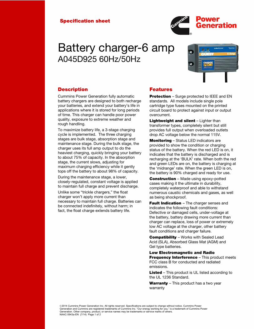
2014 Cummins Power Generation Inc. All rights reserved. Specifications are subject to change without notice. Cummins Power Generation and Cummins are registered trademarks of Cummins Inc. “Our energy working for you.” is a trademark of Cummins Power Generation. Other company, product, or service names may be trademarks or service marks of others. NAAC-5943a-EN (7/14) Page 1 of 2
Specification sheet
Battery charger-6 amp A045D925 60Hz/50Hz
Description Features
Cummins Power Generation fully automatic battery chargers are designed to both recharge your batteries, and extend your battery’s life in applications where it is stored for long periods of time. This charger can handle poor power quality, exposure to extreme weather and rough handling.
To maximize battery life, a 3-stage charging cycle is implemented. The three charging stages are bulk stage, absorption stage and maintenance stage. During the bulk stage, the charger uses its full amp output to do the heaviest charging, quickly bringing your battery to about 75% of capacity. In the absorption stage, the current slows, adjusting for maximum charging efficiency while it gently tops off the battery to about 98% of capacity.
During the maintenance stage, a lower, closely-regulated, constant voltage is applied to maintain full charge and prevent discharge.
Unlike some “trickle chargers,” the float charger won’t apply more current than necessary to maintain full charge. Batteries can be connected indefinitely, without harm; in fact, the float charge extends battery life.
Protection – Surge protected to IEEE and EN standards. All models include single pole cartridge type fuses mounted on the printed circuit board to protect against input or output overcurrent.
Lightweight and silent – Lighter than transformer types, completely silent but still provides full output when overloaded outlets drop AC voltage below the normal 115V.
Monitoring – Status LED indicators are provided to show the condition or charging status of the battery. When the red LED is on, it indicates that the battery is discharged and is recharging at the ‘BULK’ rate. When both the red and green LEDs are on, the battery is charging at the ‘midrange’ rate. When the green LED is on, the battery is 90% charged and ready for use.
Construction – Made using epoxy-potted cases making it the ultimate in durability, completely waterproof and able to withstand numerous caustic chemicals and gases, as well as being shockproof.
Fault Indication – The charger senses and indicates the following fault conditions: Defective or damaged cells, under-voltage at the battery, battery drawing more current than charger can replace, loss of power or extremely low AC voltage at the charger, other battery fault conditions and charger failure.
Compatibility – Works with Sealed Lead Acid (SLA), Absorbed Glass Mat (AGM) and Gel type batteries.
Low Electromagnetic and Radio Frequency Interference – This product meets FCC class B for conducted and radiated emissions.
Listed – This product is UL listed according to the UL 1236 Standard.
Warranty – This product has a two year warranty
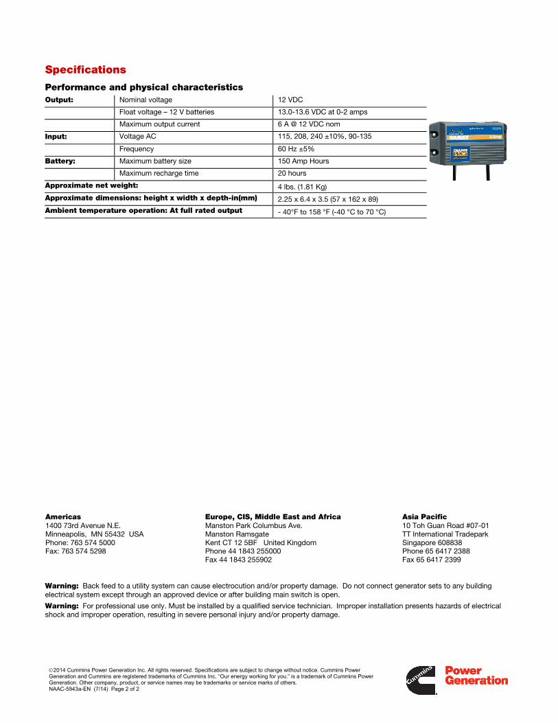
2014 Cummins Power Generation Inc. All rights reserved. Specifications are subject to change without notice. Cummins Power Generation and Cummins are registered trademarks of Cummins Inc. “Our energy working for you.” is a trademark of Cummins Power Generation. Other company, product, or service names may be trademarks or service marks of others. NAAC-5943a-EN (7/14) Page 2 of 2
Specifications
Performance and physical characteristics
Output: Nominal voltage 12 VDC
Float voltage – 12 V batteries 13.0-13.6 VDC at 0-2 amps
Maximum output current 6 A @ 12 VDC nom
Input: Voltage AC 115, 208, 240 ±10%, 90-135
Frequency 60 Hz ±5%
Battery: Maximum battery size 150 Amp Hours
Maximum recharge time 20 hours
Approximate net weight: 4 lbs. (1.81 Kg)
Approximate dimensions: height x width x depth-in(mm) 2.25 x 6.4 x 3.5 (57 x 162 x 89)
Ambient temperature operation: At full rated output - 40°F to 158 °F (-40 °C to 70 °C)
Americas 1400 73rd Avenue N.E. Minneapolis, MN 55432 USA Phone: 763 574 5000 Fax: 763 574 5298
Europe, CIS, Middle East and Africa Manston Park Columbus Ave. Manston Ramsgate Kent CT 12 5BF United Kingdom Phone 44 1843 255000 Fax 44 1843 255902
Asia Pacific 10 Toh Guan Road #07-01 TT International Tradepark Singapore 608838 Phone 65 6417 2388 Fax 65 6417 2399
Warning: Back feed to a utility system can cause electrocution and/or property damage. Do not connect generator sets to any building electrical system except through an approved device or after building main switch is open.
Warning: For professional use only. Must be installed by a qualified service technician. Improper installation presents hazards of electrical shock and improper operation, resulting in severe personal injury and/or property damage.