Embed Size (px)
Citation preview

RFID Systems – Instructor Guide
CP9329-01 RFID Systems 1 Copyright © 2014-2019 Matrix TSL
RFID Systems – Instructor Guide
CP9329-01 RFID Systems 2 Copyright © 2014-2019 Matrix TSL
CP9329
RFID Systems
Instructor Guide
RFID Systems – Instructor Guide
CP9329-01 RFID Systems 3 Copyright © 2014-2019 Matrix TSL
Contents
About this course 4 Scheme of work 5
1. Introduction to RFID .......................................................................................... 5 2. RFID system components ................................................................................. 5 3. Anatomy of a passive RFID transponder ........................................................... 5 4. The RFID reader module ................................................................................... 6 5. The RFID E-blocks2 .......................................................................................... 7 6. Using ICODE mode ........................................................................................... 8 7. Exercise 1 – Reader module communications in ICODE mode ......................... 8 8. Exercise 2 – Obtaining the UID from a transponder in ICODE mode ................. 9 9. Exercise 3 – Read transponder data in ICODE mode ...................................... 10 10. Exercise 4 – Write transponder data in ICODE mode .................................. 11 11. Using Mifare mode ...................................................................................... 12 12. Exercise 5 – Reader module communications in Mifare mode ..................... 12 13. Exercise 6 – Obtaining the UID from a Mifare Classic transponder .............. 13 14. Exercise 7 – Using security keys ................................................................. 14 15. Exercise 8 - Write data to a Mifare transponder ........................................... 15 16. Exercise 9 – Using Value format.................................................................. 16
Solutions to Exercises 17 Exercise 1 ............................................................................................................... 17 Exercise 2 ............................................................................................................... 18 Exercise 3 ............................................................................................................... 18 Exercise 4 ............................................................................................................... 19 Exercise 5 ............................................................................................................... 20 Exercise 6 ............................................................................................................... 21 Exercise 7 ............................................................................................................... 21 Exercise 8 ............................................................................................................... 21 Exercise 9 ............................................................................................................... 22
Command Syntax for both ICODE and Mifare modes 24 Additional commands for Mifare mode 26
Default Keys ........................................................................................................... 26 Store a new Key value ............................................................................................ 26 Additional commands for Value block format .......................................................... 27
The RS232 protocol 30

RFID Systems – Instructor Guide
CP9329-01 RFID Systems 4 Copyright © 2014-2019 Matrix TSL
About this course Aims: The principal aim of this course is to introduce the student to the concepts involved in RFID. On completing this course the student will have learned:
• the basic components of a RFID system; • common applications for RFID; • techniques to configure the RFID reader to enable communication with either
ICODE or Mifare transponders; • the commands and syntax used to read and write data from and to RFID
transponders.
What the student will need: To complete this course the student will need the following equipment:
• Flowcode software, version 8 or later • E-blocks2 boards including:
• a PIC or Arduino Uno processor, BL0011 or BL0055 • an RFID E-blocks2 (BL0197) with an RWD-MICODE reader module • an LED E-blocks2 (BL0167) • an LCD E-blocks2 (BL0169) • a Keypad E-blocks2 (BL0138) • ICODE RFID transponders • Mifare RFID transponders.
Using this course: This course presents the student with a number of tasks listed in the exercises in the following text. All the information needed to complete the labs is contained in the notes.
Before starting any exercises, the student should spend some time familiarising him/herself with the material on this course so that (s)he knows where to look when stuck.
Time: If you undertake all of the exercises on this course then it will take you around twelve hours.
Course conventions:
In this course we will use the following conventions:
• The main font type is Arial 11 point.
• All acronyms will be fully spelt out the first time they are mentioned. For example
o EPROM (Electrically Programmable Read Only Memory)
• Matrix products are capitalised on the first word. For example:
Multiprogrammer, Prototype board, Flowcode
• Flowcode menu instructions will be fully capitalised. For example:
o FILE...OPEN
RFID Systems – Instructor Guide
CP9329-01 RFID Systems 5 Copyright © 2014-2019 Matrix TSL
Scheme of work
Section Notes for instructors Timing
(minutes)
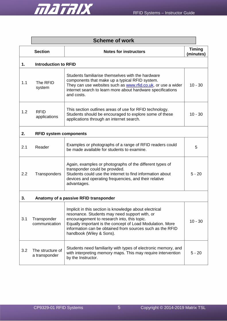
1. Introduction to RFID
1.1 The RFID system
Students familiarise themselves with the hardware components that make up a typical RFID system. They can use websites such as www.rfid.co.uk, or use a wider internet search to learn more about hardware specifications and costs.
10 - 30
1.2 RFID applications
This section outlines areas of use for RFID technology. Students should be encouraged to explore some of these applications through an internet search.
10 - 30
2. RFID system components
2.1 Reader
Examples or photographs of a range of RFID readers could be made available for students to examine.
5
2.2 Transponders
Again, examples or photographs of the different types of transponder could be provided. Students could use the internet to find information about devices and operating frequencies, and their relative advantages.
5 - 20
3. Anatomy of a passive RFID transponder
3.1 Transponder communication
Implicit in this section is knowledge about electrical resonance. Students may need support with, or encouragement to research into, this topic. Equally important is the concept of Load Modulation. More information can be obtained from sources such as the RFID handbook (Wiley & Sons).
10 - 30
3.2 The structure of a transponder
Students need familiarity with types of electronic memory, and with interpreting memory maps. This may require intervention by the Instructor.
5 - 20
RFID Systems – Instructor Guide
CP9329-01 RFID Systems 6 Copyright © 2014-2019 Matrix TSL
Section Notes for instructors Timing
(minutes)
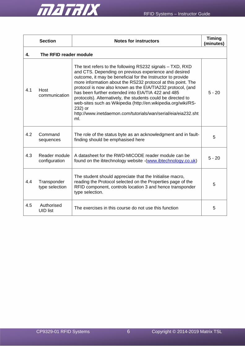
4. The RFID reader module
4.1 Host communication
The text refers to the following RS232 signals – TXD, RXD and CTS. Depending on previous experience and desired outcome, it may be beneficial for the Instructor to provide more information about the RS232 protocol at this point. The protocol is now also known as the EIA/TIA232 protocol, (and has been further extended into EIA/TIA 422 and 485 protocols). Alternatively, the students could be directed to web-sites such as Wikipedia (http://en.wikipedia.org/wiki/RS-232) or http://www.inetdaemon.com/tutorials/wan/serial/eia/eia232.shtml.
5 - 20
4.2 Command sequences
The role of the status byte as an acknowledgment and in fault-finding should be emphasised here
5
4.3 Reader module configuration
A datasheet for the RWD-MICODE reader module can be found on the ibtechnology website -(www.ibtechnology.co.uk)
5 - 20
4.4 Transponder type selection
The student should appreciate that the Initialise macro, reading the Protocol selected on the Properties page of the RFID component, controls location 3 and hence transponder type selection.
5
4.5 Authorised UID list
The exercises in this course do not use this function
5
RFID Systems – Instructor Guide
CP9329-01 RFID Systems 7 Copyright © 2014-2019 Matrix TSL
Section Notes for instructors Timing
(minutes)
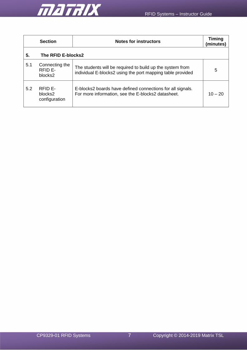
5. The RFID E-blocks2
5.1 Connecting the RFID E-blocks2
The students will be required to build up the system from individual E-blocks2 using the port mapping table provided
5
5.2 RFID E-blocks2 configuration
E-blocks2 boards have defined connections for all signals. For more information, see the E-blocks2 datasheet.
10 – 20
RFID Systems – Instructor Guide
CP9329-01 RFID Systems 8 Copyright © 2014-2019 Matrix TSL
Section Notes for instructors Timing
(minutes)
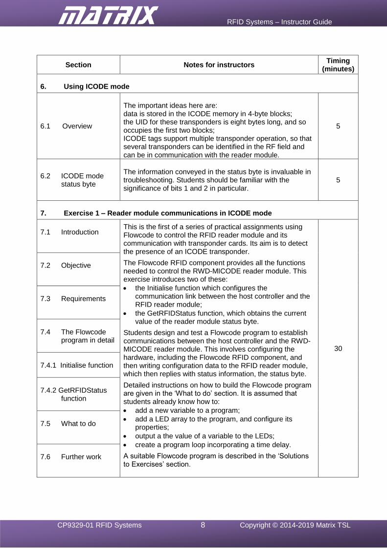
6. Using ICODE mode
6.1 Overview
The important ideas here are: data is stored in the ICODE memory in 4-byte blocks; the UID for these transponders is eight bytes long, and so occupies the first two blocks; ICODE tags support multiple transponder operation, so that several transponders can be identified in the RF field and can be in communication with the reader module.
5
6.2 ICODE mode status byte
The information conveyed in the status byte is invaluable in troubleshooting. Students should be familiar with the significance of bits 1 and 2 in particular.
5
7. Exercise 1 – Reader module communications in ICODE mode
7.1 Introduction
This is the first of a series of practical assignments using Flowcode to control the RFID reader module and its communication with transponder cards. Its aim is to detect the presence of an ICODE transponder.
The Flowcode RFID component provides all the functions needed to control the RWD-MICODE reader module. This exercise introduces two of these:
• the Initialise function which configures the communication link between the host controller and the RFID reader module;
• the GetRFIDStatus function, which obtains the current value of the reader module status byte.
Students design and test a Flowcode program to establish communications between the host controller and the RWD-MICODE reader module. This involves configuring the hardware, including the Flowcode RFID component, and then writing configuration data to the RFID reader module, which then replies with status information, the status byte.
Detailed instructions on how to build the Flowcode program are given in the ‘What to do’ section. It is assumed that students already know how to:
• add a new variable to a program;
• add a LED array to the program, and configure its properties;
• output a the value of a variable to the LEDs;
• create a program loop incorporating a time delay.
A suitable Flowcode program is described in the ‘Solutions to Exercises’ section.
30
7.2 Objective
7.3 Requirements
7.4 The Flowcode
program in detail
7.4.1 Initialise function
7.4.2 GetRFIDStatus
function
7.5 What to do
7.6 Further work
RFID Systems – Instructor Guide
CP9329-01 RFID Systems 9 Copyright © 2014-2019 Matrix TSL
Section Notes for instructors Timing
(minutes)
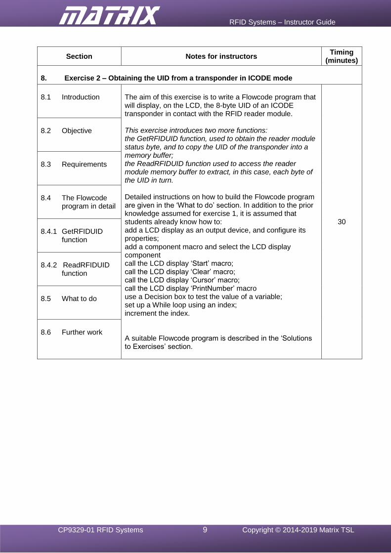
8. Exercise 2 – Obtaining the UID from a transponder in ICODE mode
8.1 Introduction
The aim of this exercise is to write a Flowcode program that will display, on the LCD, the 8-byte UID of an ICODE transponder in contact with the RFID reader module. This exercise introduces two more functions: the GetRFIDUID function, used to obtain the reader module status byte, and to copy the UID of the transponder into a memory buffer; the ReadRFIDUID function used to access the reader module memory buffer to extract, in this case, each byte of the UID in turn. Detailed instructions on how to build the Flowcode program are given in the ‘What to do’ section. In addition to the prior knowledge assumed for exercise 1, it is assumed that students already know how to: add a LCD display as an output device, and configure its properties; add a component macro and select the LCD display component call the LCD display ‘Start’ macro; call the LCD display ‘Clear’ macro; call the LCD display ‘Cursor’ macro; call the LCD display ‘PrintNumber’ macro use a Decision box to test the value of a variable; set up a While loop using an index; increment the index. A suitable Flowcode program is described in the ‘Solutions to Exercises’ section.
30
8.2 Objective
8.3 Requirements
8.4 The Flowcode
program in detail
8.4.1 GetRFIDUID
function
8.4.2 ReadRFIDUID
function
8.5 What to do
8.6 Further work
RFID Systems – Instructor Guide
CP9329-01 RFID Systems 10 Copyright © 2014-2019 Matrix TSL
Section Notes for instructors Timing
(minutes)
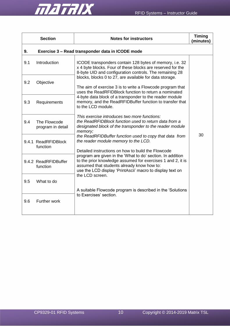
9. Exercise 3 – Read transponder data in ICODE mode
9.1 Introduction
ICODE transponders contain 128 bytes of memory, i.e. 32 x 4 byte blocks. Four of these blocks are reserved for the 8-byte UID and configuration controls. The remaining 28 blocks, blocks 0 to 27, are available for data storage. The aim of exercise 3 is to write a Flowcode program that uses the ReadRFIDBlock function to return a nominated 4-byte data block of a transponder to the reader module memory, and the ReadRFIDBuffer function to transfer that to the LCD module. This exercise introduces two more functions: the ReadRFIDBlock function used to return data from a designated block of the transponder to the reader module memory; the ReadRFIDBuffer function used to copy that data from the reader module memory to the LCD. Detailed instructions on how to build the Flowcode program are given in the ‘What to do’ section. In addition to the prior knowledge assumed for exercises 1 and 2, it is assumed that students already know how to: use the LCD display ‘PrintAscii’ macro to display text on the LCD screen. A suitable Flowcode program is described in the ‘Solutions to Exercises’ section.
30
9.2 Objective
9.3 Requirements
9.4 The Flowcode
program in detail
9.4.1 ReadRFIDBlock
function
9.4.2 ReadRFIDBuffer
function
9.5 What to do
9.6 Further work
RFID Systems – Instructor Guide
CP9329-01 RFID Systems 11 Copyright © 2014-2019 Matrix TSL
Section Notes for instructors Timing
(minutes)
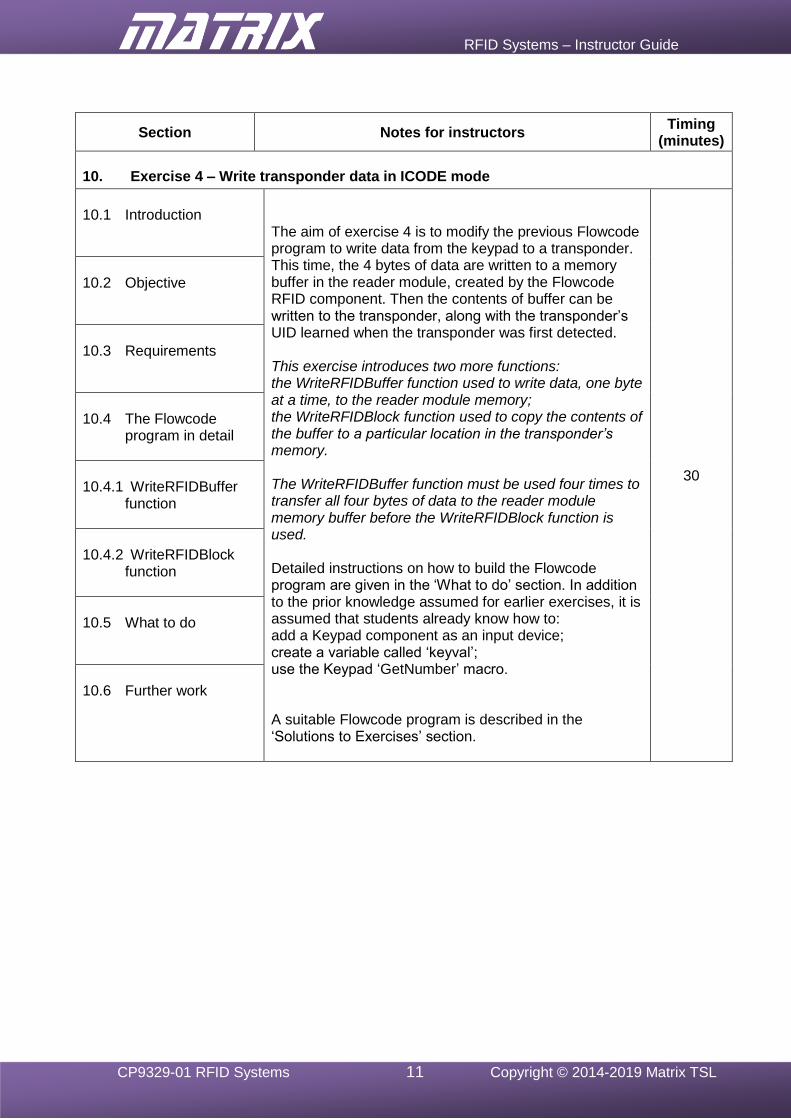
10. Exercise 4 – Write transponder data in ICODE mode
10.1 Introduction
The aim of exercise 4 is to modify the previous Flowcode program to write data from the keypad to a transponder. This time, the 4 bytes of data are written to a memory buffer in the reader module, created by the Flowcode RFID component. Then the contents of buffer can be written to the transponder, along with the transponder’s UID learned when the transponder was first detected. This exercise introduces two more functions: the WriteRFIDBuffer function used to write data, one byte at a time, to the reader module memory; the WriteRFIDBlock function used to copy the contents of the buffer to a particular location in the transponder’s memory. The WriteRFIDBuffer function must be used four times to transfer all four bytes of data to the reader module memory buffer before the WriteRFIDBlock function is used. Detailed instructions on how to build the Flowcode program are given in the ‘What to do’ section. In addition to the prior knowledge assumed for earlier exercises, it is assumed that students already know how to: add a Keypad component as an input device; create a variable called ‘keyval’; use the Keypad ‘GetNumber’ macro. A suitable Flowcode program is described in the ‘Solutions to Exercises’ section.
30
10.2 Objective
10.3 Requirements
10.4 The Flowcode
program in detail
10.4.1 WriteRFIDBuffer
function
10.4.2 WriteRFIDBlock
function
10.5 What to do
10.6 Further work

RFID Systems – Instructor Guide
CP9329-01 RFID Systems 12 Copyright © 2014-2019 Matrix TSL
Section Notes for instructors Timing
(minutes)
11. Using Mifare mode
11.1 Overview The important ideas here are: there are three types of Mifare card, 1K, 4K and Ultralight; the first two of these types are compatible, and differ only in their storage capacity, but these are not compatible with Ultralight transponders; data storage can be configured in one of two forms: standard format, where each block stores sixteen bytes of data; ‘Value’ format, a more secure format used for e-purse applications, incorporating error-checking. three additional commands are available when using the Value format,: Increment – add a 4-byte value to the value in the memory block; Decrement – subtract a 4-byte value from the value in the memory block; Transfer – copy the contents of the memory block to another location. transponder read / write commands require the use of security keys stored in the reader module and transponder;
15
11.2 Mifare mode status byte
As in ICODE mode, the information conveyed is important in troubleshooting. Bits 1 and 2 keep the sam significance, but in addition, bits 3 and 4 identify the type of Mifare card detected.
5
12. Exercise 5 – Reader module communications in Mifare mode
(This is the Mifare equivalent of exercise 1.)
12.1 Introduction
This exercise has the same aims as exercise 1, but uses Mifare mode. Students could start practical work at this point, and then tackle ICODE mode after completing exercise 9. For that reason, detailed instructions are given on building the Flowcode program. If students are starting practical work here, the instructor should note the assumed prior knowledge of Flowcode programming detailed in the notes for Exercise 1.
Students could modify the program developed in Exercise 1, or start a new program for this exercise.
A suitable Flowcode program is described in the ‘Solutions to Exercises’ section.
30
12.2 Objective
12.3 Requirements
12.4 The Flowcode program in detail
12.4.1 Initialise function
12.4.2 GetRFIDStatus function
12.5 What to do
12.6 Further work
RFID Systems – Instructor Guide
CP9329-01 RFID Systems 13 Copyright © 2014-2019 Matrix TSL
Section Notes for instructors Timing
(minutes)
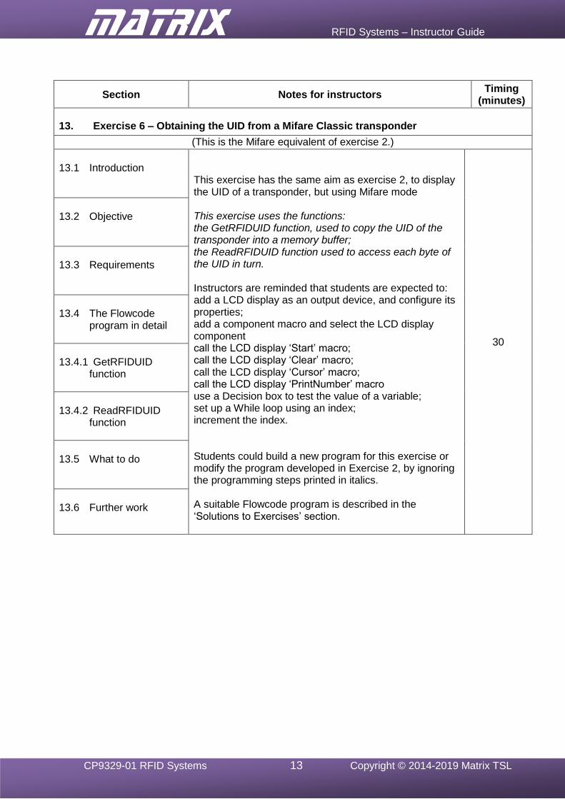
13. Exercise 6 – Obtaining the UID from a Mifare Classic transponder
(This is the Mifare equivalent of exercise 2.)
13.1 Introduction
This exercise has the same aim as exercise 2, to display the UID of a transponder, but using Mifare mode This exercise uses the functions: the GetRFIDUID function, used to copy the UID of the transponder into a memory buffer; the ReadRFIDUID function used to access each byte of the UID in turn. Instructors are reminded that students are expected to: add a LCD display as an output device, and configure its properties; add a component macro and select the LCD display component call the LCD display ‘Start’ macro; call the LCD display ‘Clear’ macro; call the LCD display ‘Cursor’ macro; call the LCD display ‘PrintNumber’ macro use a Decision box to test the value of a variable; set up a While loop using an index; increment the index. Students could build a new program for this exercise or modify the program developed in Exercise 2, by ignoring the programming steps printed in italics. A suitable Flowcode program is described in the ‘Solutions to Exercises’ section.
30
13.2 Objective
13.3 Requirements
13.4 The Flowcode
program in detail
13.4.1 GetRFIDUID
function
13.4.2 ReadRFIDUID
function
13.5 What to do
13.6 Further work
RFID Systems – Instructor Guide
CP9329-01 RFID Systems 14 Copyright © 2014-2019 Matrix TSL
Section Notes for instructors Timing
(minutes)
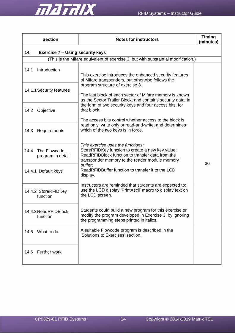
14. Exercise 7 – Using security keys
(This is the Mifare equivalent of exercise 3, but with substantial modification.)
14.1 Introduction
This exercise introduces the enhanced security features of Mifare transponders, but otherwise follows the program structure of exercise 3. The last block of each sector of Mifare memory is known as the Sector Trailer Block, and contains security data, in the form of two security keys and four access bits, for that block. The access bits control whether access to the block is read only, write only or read-and-write, and determines which of the two keys is in force. This exercise uses the functions: StoreRFIDKey function to create a new key value; ReadRFIDBlock function to transfer data from the transponder memory to the reader module memory buffer; ReadRFIDBuffer function to transfer it to the LCD display. Instructors are reminded that students are expected to: use the LCD display ‘PrintAscii’ macro to display text on the LCD screen. Students could build a new program for this exercise or modify the program developed in Exercise 3, by ignoring the programming steps printed in italics. A suitable Flowcode program is described in the ‘Solutions to Exercises’ section.
30
14.1.1 Security features
14.2 Objective
14.3 Requirements
14.4 The Flowcode
program in detail
14.4.1 Default keys
14.4.2 StoreRFIDKey
function
14.4.3 ReadRFIDBlock
function
14.5 What to do
14.6 Further work

RFID Systems – Instructor Guide
CP9329-01 RFID Systems 15 Copyright © 2014-2019 Matrix TSL
Section Notes for instructors Timing
(minutes)
15. Exercise 8 - Write data to a Mifare transponder
(This is the Mifare equivalent of exercise 4.)
15.1 Introduction
This exercise has the same aim as exercise 4 and has substantially the same program structure. Students could build a new program for this exercise or could modify the program developed in Exercise 4, by ignoring the programming steps printed in italics. A suitable Flowcode program is described in the ‘Solutions to Exercises’ section. 30
15.2 Objective
15.3 Requirements
15.4 The Flowcode
program in detail
15.4.1 GetRFIDUID
function
15.4.2 ReadRFIDUID
function
15.5 What to do
15.6 Further work
RFID Systems – Instructor Guide
CP9329-01 RFID Systems 16 Copyright © 2014-2019 Matrix TSL
Section Notes for instructors Timing
(minutes)
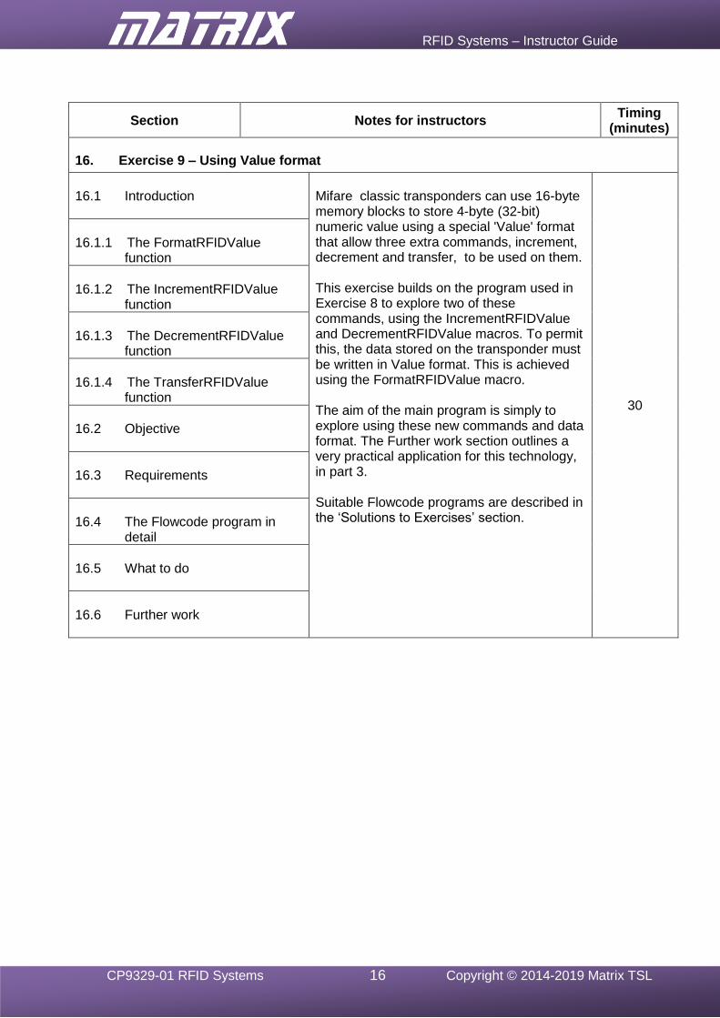
16. Exercise 9 – Using Value format
16.1 Introduction
Mifare classic transponders can use 16-byte memory blocks to store 4-byte (32-bit) numeric value using a special 'Value' format that allow three extra commands, increment, decrement and transfer, to be used on them. This exercise builds on the program used in Exercise 8 to explore two of these commands, using the IncrementRFIDValue and DecrementRFIDValue macros. To permit this, the data stored on the transponder must be written in Value format. This is achieved using the FormatRFIDValue macro. The aim of the main program is simply to explore using these new commands and data format. The Further work section outlines a very practical application for this technology, in part 3. Suitable Flowcode programs are described in the ‘Solutions to Exercises’ section.
30
16.1.1 The FormatRFIDValue
function
16.1.2 The IncrementRFIDValue
function
16.1.3 The DecrementRFIDValue
function
16.1.4 The TransferRFIDValue
function
16.2 Objective
16.3 Requirements
16.4 The Flowcode program in
detail
16.5 What to do
16.6 Further work
RFID Systems – Instructor Guide
CP9329-01 RFID Systems 17 Copyright © 2014-2019 Matrix TSL
Solutions to Exercises
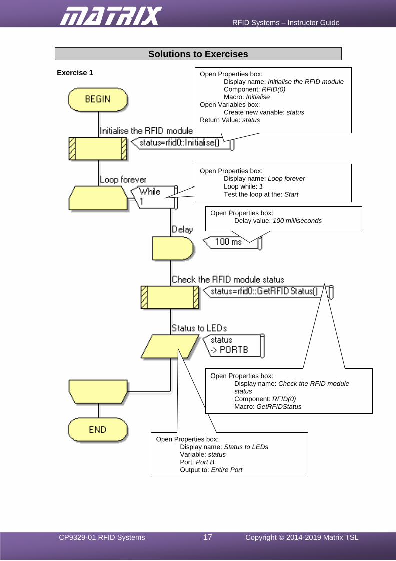
Exercise 1
Open Properties box: Display name: Initialise the RFID module Component: RFID(0) Macro: Initialise
Open Variables box: Create new variable: status
Return Value: status
Open Properties box: Display name: Loop forever Loop while: 1 Test the loop at the: Start
Open Properties box: Delay value: 100 milliseconds
Open Properties box: Display name: Status to LEDs Variable: status Port: Port B Output to: Entire Port
Open Properties box: Display name: Check the RFID module status Component: RFID(0) Macro: GetRFIDStatus
Return Value: status
RFID Systems – Instructor Guide
CP9329-01 RFID Systems 18 Copyright © 2014-2019 Matrix TSL
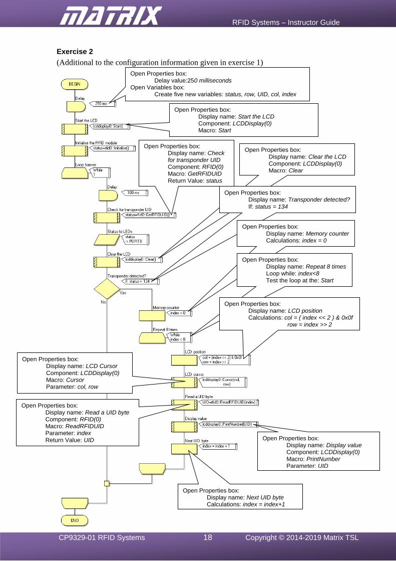
Exercise 2
(Additional to the configuration information given in exercise 1)
Open Properties box: Delay value:250 milliseconds
Open Variables box: Create five new variables: status, row, UID, col, index
Open Properties box: Display name: Start the LCD Component: LCDDisplay(0) Macro: Start
Open Properties box: Display name: Check for transponder UID Component: RFID(0) Macro: GetRFIDUID Return Value: status
Open Properties box: Display name: Clear the LCD Component: LCDDisplay(0) Macro: Clear
Open Properties box: Display name: Transponder detected?
If: status = 134
Open Properties box: Display name: Next UID byte Calculations: index = index+1
Open Properties box: Display name: Display value Component: LCDDisplay(0) Macro: PrintNumber Parameter: UID
Open Properties box: Display name: Read a UID byte Component: RFID(0) Macro: ReadRFIDUID Parameter: index Return Value: UID
Open Properties box: Display name: LCD Cursor Component: LCDDisplay(0) Macro: Cursor Parameter: col, row
Open Properties box: Display name: Memory counter Calculations: index = 0
Open Properties box: Display name: Repeat 8 times Loop while: index<8 Test the loop at the: Start
Open Properties box: Display name: LCD position Calculations: col = ( index << 2 ) & 0x0f row = index >> 2
RFID Systems – Instructor Guide
CP9329-01 RFID Systems 19 Copyright © 2014-2019 Matrix TSL
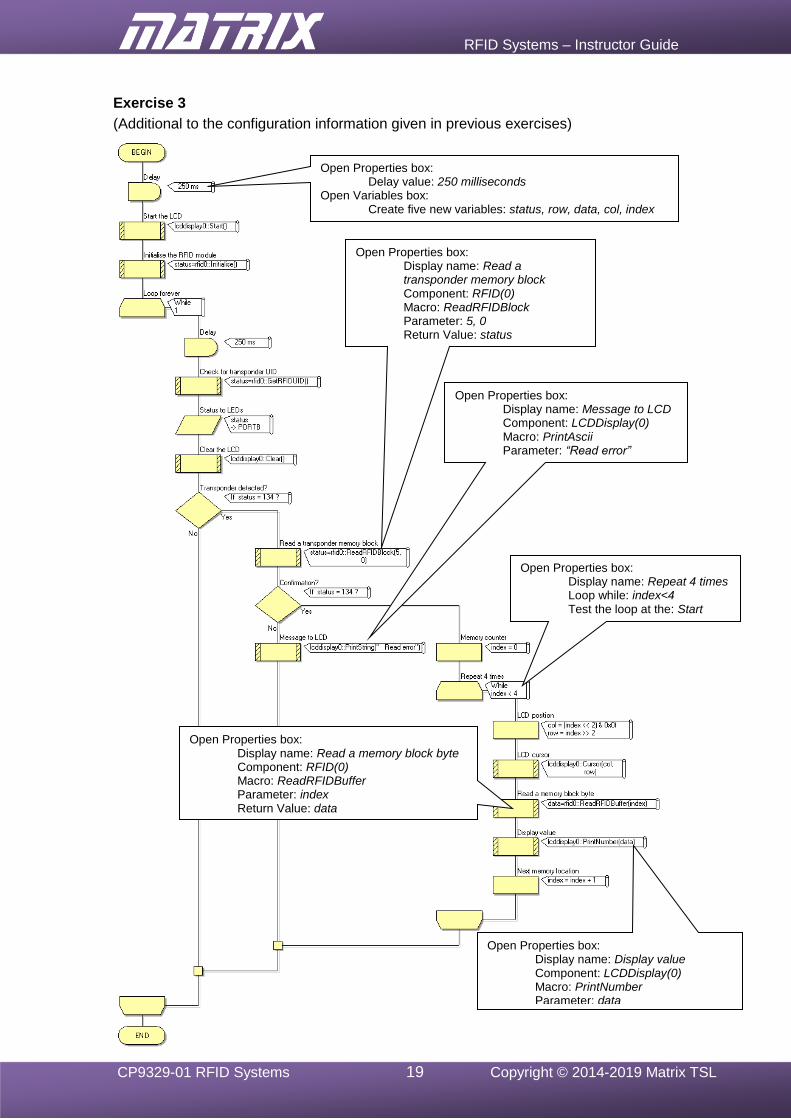
Exercise 3
(Additional to the configuration information given in previous exercises)
Open Properties box: Display name: Read a transponder memory block Component: RFID(0) Macro: ReadRFIDBlock Parameter: 5, 0 Return Value: status
Open Properties box: Display name: Message to LCD Component: LCDDisplay(0) Macro: PrintAscii Parameter: “Read error”
Open Properties box: Display name: Repeat 4 times Loop while: index<4 Test the loop at the: Start
Open Properties box: Display name: Read a memory block byte Component: RFID(0) Macro: ReadRFIDBuffer Parameter: index Return Value: data
Open Properties box: Delay value: 250 milliseconds
Open Variables box: Create five new variables: status, row, data, col, index
Open Properties box: Display name: Display value Component: LCDDisplay(0) Macro: PrintNumber Parameter: data
RFID Systems – Instructor Guide
CP9329-01 RFID Systems 20 Copyright © 2014-2019 Matrix TSL
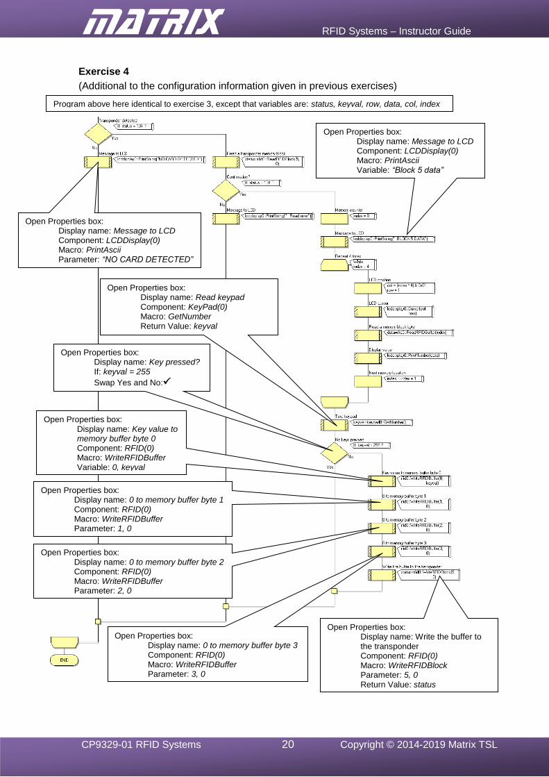
Exercise 4
(Additional to the configuration information given in previous exercises)
Program above here identical to exercise 3, except that variables are: status, keyval, row, data, col, index
Open Properties box: Display name: Message to LCD Component: LCDDisplay(0) Macro: PrintAscii Parameter: “NO CARD DETECTED”
Open Properties box: Display name: Message to LCD Component: LCDDisplay(0) Macro: PrintAscii Variable: “Block 5 data”
Open Properties box: Display name: Read keypad Component: KeyPad(0) Macro: GetNumber Return Value: keyval
Open Properties box: Display name: Key pressed? If: keyval = 255
Swap Yes and No:✓
Open Properties box: Display name: Key value to memory buffer byte 0 Component: RFID(0) Macro: WriteRFIDBuffer Variable: 0, keyval
Open Properties box: Display name: 0 to memory buffer byte 1 Component: RFID(0) Macro: WriteRFIDBuffer Parameter: 1, 0
Open Properties box: Display name: 0 to memory buffer byte 2 Component: RFID(0) Macro: WriteRFIDBuffer Parameter: 2, 0
Open Properties box: Display name: 0 to memory buffer byte 3 Component: RFID(0) Macro: WriteRFIDBuffer Parameter: 3, 0
Open Properties box: Display name: Write the buffer to the transponder Component: RFID(0) Macro: WriteRFIDBlock Parameter: 5, 0 Return Value: status
RFID Systems – Instructor Guide
CP9329-01 RFID Systems 21 Copyright © 2014-2019 Matrix TSL
Exercise 5
The Flowcode flowchart is identical to that for Exercise 1. Open the RFID component RFID(0) Properties box, and select the Mifare 1K/4K protocol.
Exercise 6
The Flowcode flowchart is identical to that for Exercise 2. Open the RFID component RFID(0) Properties box, and select the Mifare 1K/4K protocol.
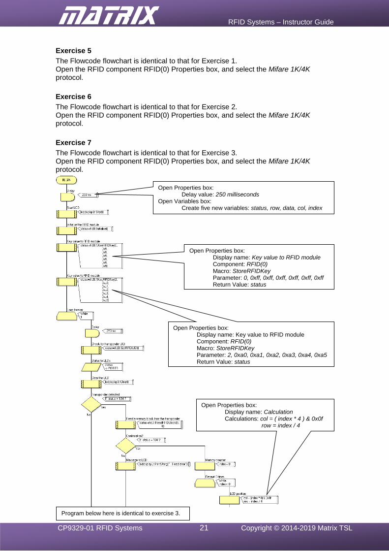
Exercise 7
The Flowcode flowchart is identical to that for Exercise 3. Open the RFID component RFID(0) Properties box, and select the Mifare 1K/4K protocol.
Program below here is identical to exercise 3.
Open Properties box: Delay value: 250 milliseconds
Open Variables box: Create five new variables: status, row, data, col, index
Open Properties box: Display name: Key value to RFID module Component: RFID(0) Macro: StoreRFIDKey Parameter: 0, 0xff, 0xff, 0xff, 0xff, 0xff, 0xff Return Value: status
Open Properties box: Display name: Key value to RFID module Component: RFID(0) Macro: StoreRFIDKey Parameter: 2, 0xa0, 0xa1, 0xa2, 0xa3, 0xa4, 0xa5 Return Value: status
Open Properties box: Display name: Calculation Calculations: col = ( index * 4 ) & 0x0f row = index / 4
RFID Systems – Instructor Guide
CP9329-01 RFID Systems 22 Copyright © 2014-2019 Matrix TSL
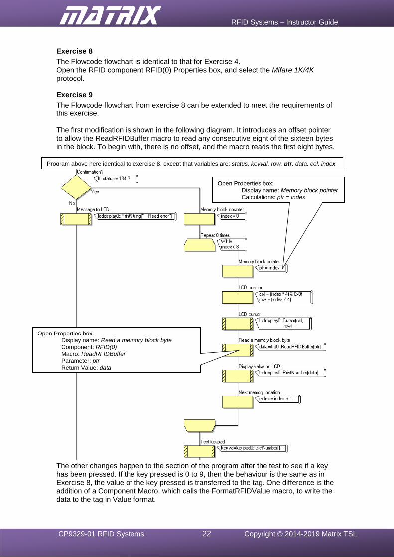
Exercise 8
The Flowcode flowchart is identical to that for Exercise 4. Open the RFID component RFID(0) Properties box, and select the Mifare 1K/4K protocol.
Exercise 9
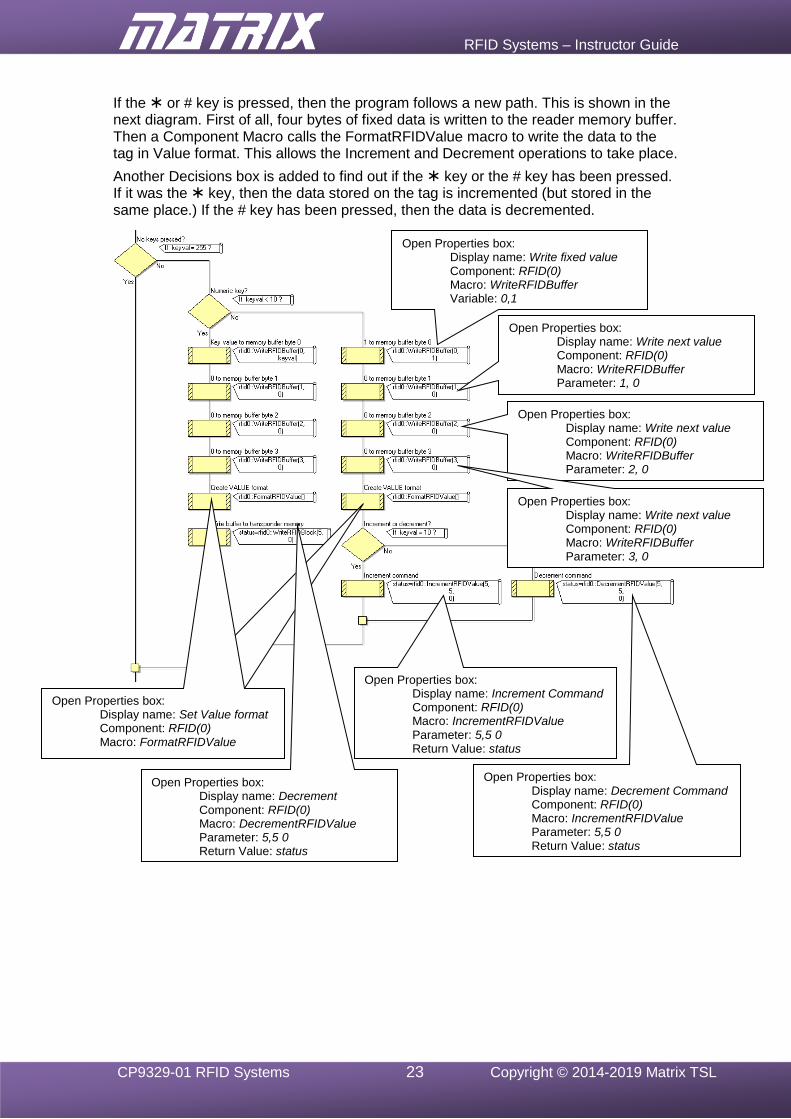
The Flowcode flowchart from exercise 8 can be extended to meet the requirements of this exercise. The first modification is shown in the following diagram. It introduces an offset pointer to allow the ReadRFIDBuffer macro to read any consecutive eight of the sixteen bytes in the block. To begin with, there is no offset, and the macro reads the first eight bytes.
The other changes happen to the section of the program after the test to see if a key has been pressed. If the key pressed is 0 to 9, then the behaviour is the same as in Exercise 8, the value of the key pressed is transferred to the tag. One difference is the addition of a Component Macro, which calls the FormatRFIDValue macro, to write the data to the tag in Value format.
Open Properties box: Display name: Memory block pointer Calculations: ptr = index
Program above here identical to exercise 8, except that variables are: status, keyval, row, ptr, data, col, index
Open Properties box: Display name: Read a memory block byte Component: RFID(0) Macro: ReadRFIDBuffer Parameter: ptr Return Value: data
RFID Systems – Instructor Guide
CP9329-01 RFID Systems 23 Copyright © 2014-2019 Matrix TSL
If the or # key is pressed, then the program follows a new path. This is shown in the next diagram. First of all, four bytes of fixed data is written to the reader memory buffer. Then a Component Macro calls the FormatRFIDValue macro to write the data to the tag in Value format. This allows the Increment and Decrement operations to take place.
Another Decisions box is added to find out if the key or the # key has been pressed. If it was the key, then the data stored on the tag is incremented (but stored in the same place.) If the # key has been pressed, then the data is decremented.
Open Properties box: Display name: Set Value format Component: RFID(0) Macro: FormatRFIDValue
Open Properties box: Display name: Set Value format Component: RFID(0) Macro: FormatRFIDValue
Open Properties box: Display name: Write fixed value Component: RFID(0) Macro: WriteRFIDBuffer Variable: 0,1
Open Properties box: Display name: Write next value Component: RFID(0) Macro: WriteRFIDBuffer Parameter: 1, 0
Open Properties box: Display name: Write next value Component: RFID(0) Macro: WriteRFIDBuffer Parameter: 2, 0
Open Properties box: Display name: Write next value Component: RFID(0) Macro: WriteRFIDBuffer Parameter: 3, 0
Open Properties box: Display name: Decrement Component: RFID(0) Macro: DecrementRFIDValue Parameter: 5,5 0 Return Value: status
Open Properties box: Display name: Increment Command Component: RFID(0) Macro: IncrementRFIDValue Parameter: 5,5 0 Return Value: status
Open Properties box: Display name: Decrement Command Component: RFID(0) Macro: IncrementRFIDValue Parameter: 5,5 0 Return Value: status
RFID Systems – Instructor Guide
CP9329-01 RFID Systems 24 Copyright © 2014-2019 Matrix TSL
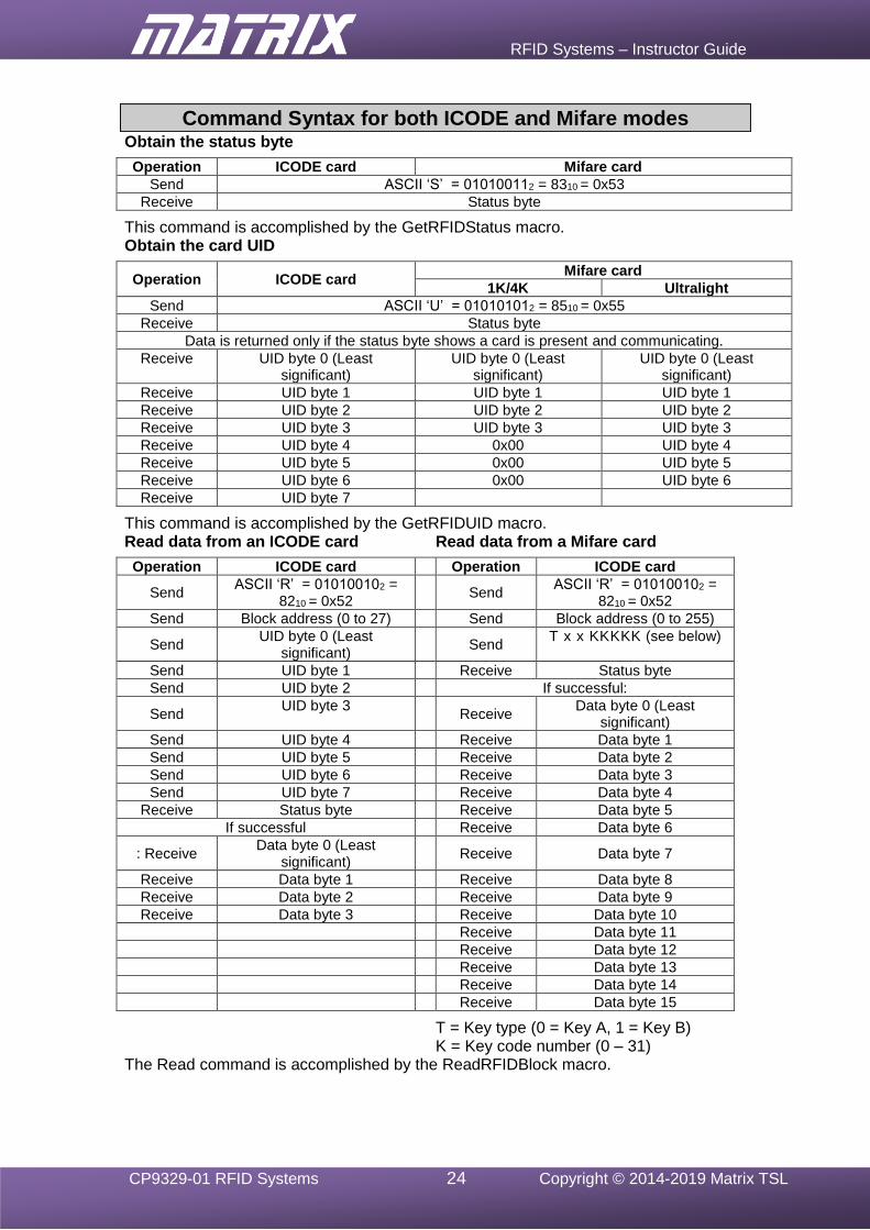
Command Syntax for both ICODE and Mifare modes
Obtain the status byte
Operation ICODE card Mifare card
Send ASCII ‘S’ = 010100112 = 8310 = 0x53
Receive Status byte
This command is accomplished by the GetRFIDStatus macro. Obtain the card UID
Operation ICODE card Mifare card
1K/4K Ultralight
Send ASCII ‘U’ = 010101012 = 8510 = 0x55
Receive Status byte
Data is returned only if the status byte shows a card is present and communicating.
Receive UID byte 0 (Least significant)
UID byte 0 (Least significant)
UID byte 0 (Least significant)
Receive UID byte 1 UID byte 1 UID byte 1
Receive UID byte 2 UID byte 2 UID byte 2
Receive UID byte 3 UID byte 3 UID byte 3
Receive UID byte 4 0x00 UID byte 4
Receive UID byte 5 0x00 UID byte 5
Receive UID byte 6 0x00 UID byte 6
Receive UID byte 7
This command is accomplished by the GetRFIDUID macro. Read data from an ICODE card Read data from a Mifare card
Operation ICODE card Operation ICODE card
Send ASCII ‘R’ = 010100102 =
8210 = 0x52
Send ASCII ‘R’ = 010100102 =
8210 = 0x52
Send Block address (0 to 27) Send Block address (0 to 255)
Send UID byte 0 (Least
significant)
Send T x x KKKKK (see below)
Send UID byte 1 Receive Status byte
Send UID byte 2 If successful:
Send UID byte 3
Receive Data byte 0 (Least
significant)
Send UID byte 4 Receive Data byte 1
Send UID byte 5 Receive Data byte 2
Send UID byte 6 Receive Data byte 3
Send UID byte 7 Receive Data byte 4
Receive Status byte Receive Data byte 5
If successful Receive Data byte 6
: Receive Data byte 0 (Least
significant)
Receive Data byte 7
Receive Data byte 1 Receive Data byte 8
Receive Data byte 2 Receive Data byte 9
Receive Data byte 3 Receive Data byte 10
Receive Data byte 11
Receive Data byte 12
Receive Data byte 13
Receive Data byte 14
Receive Data byte 15
T = Key type (0 = Key A, 1 = Key B) K = Key code number (0 – 31) The Read command is accomplished by the ReadRFIDBlock macro.
RFID Systems – Instructor Guide
CP9329-01 RFID Systems 25 Copyright © 2014-2019 Matrix TSL
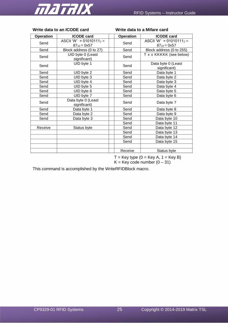
Write data to an ICODE card Write data to a Mifare card
Operation ICODE card Operation ICODE card
Send ASCII ‘W’ = 010101112 =
8710 = 0x57
Send ASCII ‘W’ = 010101112 =
8710 = 0x57
Send Block address (0 to 27) Send Block address (0 to 255)
Send UID byte 0 (Least
significant)
Send T x x KKKKK (see below)
Send UID byte 1
Send Data byte 0 (Least
significant)
Send UID byte 2 Send Data byte 1
Send UID byte 3 Send Data byte 2
Send UID byte 4 Send Data byte 3
Send UID byte 5 Send Data byte 4
Send UID byte 6 Send Data byte 5
Send UID byte 7 Send Data byte 6
Send Data byte 0 (Least
significant)
Send Data byte 7
Send Data byte 1 Send Data byte 8
Send Data byte 2 Send Data byte 9
Send Data byte 3 Send Data byte 10
Send Data byte 11
Receive Status byte Send Data byte 12
Send Data byte 13
Send Data byte 14
Send Data byte 15
Receive Status byte
T = Key type (0 = Key A, 1 = Key B) K = Key code number (0 – 31)
This command is accomplished by the WriteRFIDBlock macro.
RFID Systems – Instructor Guide
CP9329-01 RFID Systems 26 Copyright © 2014-2019 Matrix TSL
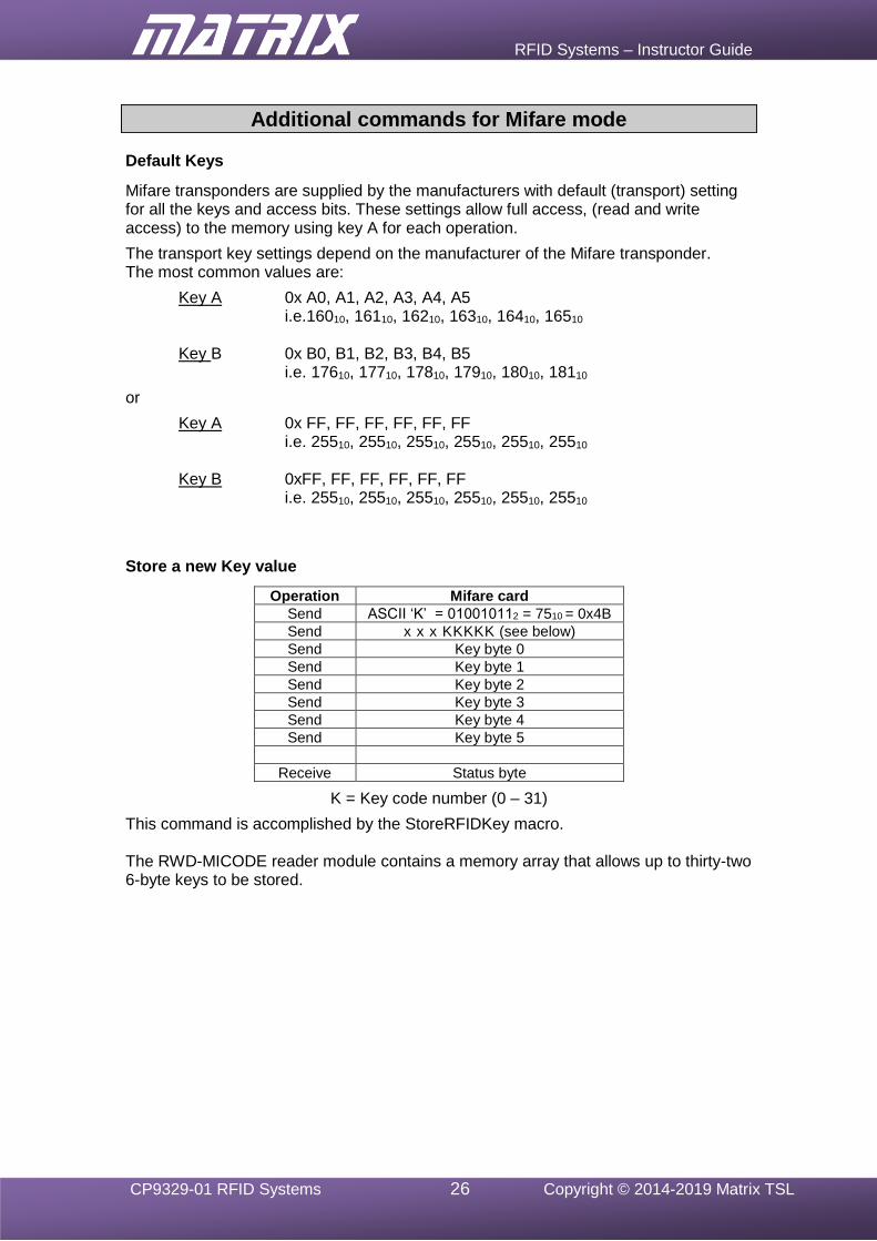
Additional commands for Mifare mode
Default Keys
Mifare transponders are supplied by the manufacturers with default (transport) setting for all the keys and access bits. These settings allow full access, (read and write access) to the memory using key A for each operation.
The transport key settings depend on the manufacturer of the Mifare transponder. The most common values are:
Key A 0x A0, A1, A2, A3, A4, A5 i.e.16010, 16110, 16210, 16310, 16410, 16510 Key B 0x B0, B1, B2, B3, B4, B5 i.e. 17610, 17710, 17810, 17910, 18010, 18110
or
Key A 0x FF, FF, FF, FF, FF, FF i.e. 25510, 25510, 25510, 25510, 25510, 25510 Key B 0xFF, FF, FF, FF, FF, FF i.e. 25510, 25510, 25510, 25510, 25510, 25510
Store a new Key value
Operation Mifare card
Send ASCII ‘K’ = 010010112 = 7510 = 0x4B
Send x x x KKKKK (see below)
Send Key byte 0
Send Key byte 1
Send Key byte 2
Send Key byte 3
Send Key byte 4
Send Key byte 5
Receive Status byte
K = Key code number (0 – 31)
This command is accomplished by the StoreRFIDKey macro.
The RWD-MICODE reader module contains a memory array that allows up to thirty-two 6-byte keys to be stored.
RFID Systems – Instructor Guide
CP9329-01 RFID Systems 27 Copyright © 2014-2019 Matrix TSL
Additional commands for Value block format
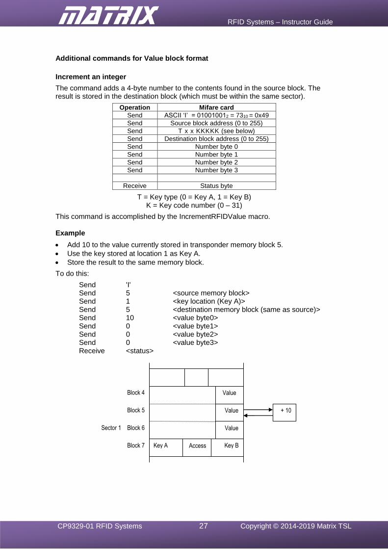
Increment an integer
The command adds a 4-byte number to the contents found in the source block. The result is stored in the destination block (which must be within the same sector).
Operation Mifare card
Send ASCII ‘I’ = 010010012 = 7310 = 0x49
Send Source block address (0 to 255)
Send T x x KKKKK (see below)
Send Destination block address (0 to 255)
Send Number byte 0
Send Number byte 1
Send Number byte 2
Send Number byte 3
Receive Status byte
T = Key type (0 = Key A, 1 = Key B) K = Key code number (0 – 31)
This command is accomplished by the IncrementRFIDValue macro. Example
• Add 10 to the value currently stored in transponder memory block 5.
• Use the key stored at location 1 as Key A.
• Store the result to the same memory block.
To do this:
Send 'I' Send 5 <source memory block> Send 1 <key location (Key A)> Send 5 <destination memory block (same as source)> Send 10 <value byte0> Send 0 <value byte1> Send 0 <value byte2> Send 0 <value byte3> Receive <status>
Block 7
Block 6
Block 5
Block 4
Sector 1
+ 10
Value
Value
Value
Key A Key B Access
RFID Systems – Instructor Guide
CP9329-01 RFID Systems 28 Copyright © 2014-2019 Matrix TSL
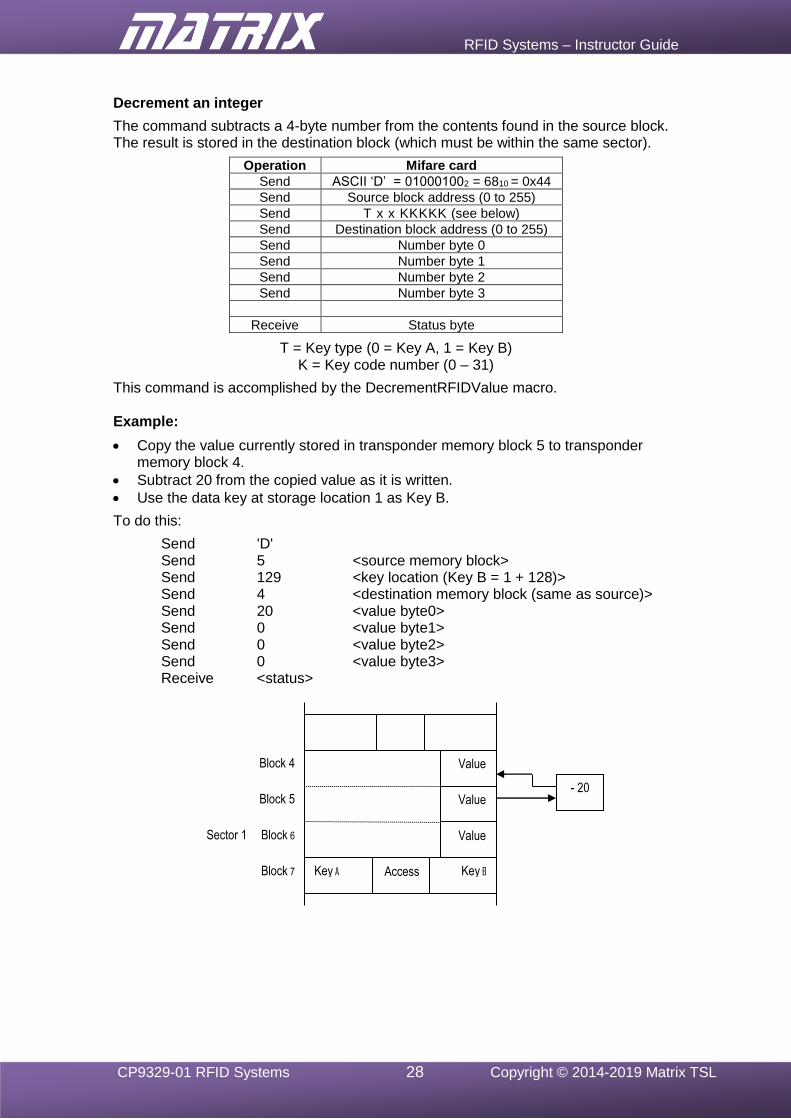
Decrement an integer
The command subtracts a 4-byte number from the contents found in the source block. The result is stored in the destination block (which must be within the same sector).
Operation Mifare card
Send ASCII ‘D’ = 010001002 = 6810 = 0x44
Send Source block address (0 to 255)
Send T x x KKKKK (see below)
Send Destination block address (0 to 255)
Send Number byte 0
Send Number byte 1
Send Number byte 2
Send Number byte 3
Receive Status byte
T = Key type (0 = Key A, 1 = Key B) K = Key code number (0 – 31)
This command is accomplished by the DecrementRFIDValue macro. Example:
• Copy the value currently stored in transponder memory block 5 to transponder memory block 4.
• Subtract 20 from the copied value as it is written.
• Use the data key at storage location 1 as Key B.
To do this:
Send 'D' Send 5 <source memory block> Send 129 <key location (Key B = 1 + 128)> Send 4 <destination memory block (same as source)> Send 20 <value byte0> Send 0 <value byte1> Send 0 <value byte2> Send 0 <value byte3> Receive <status>
Block 7
Block 6
Block 5
Block 4
Sector 1
- 20
Value
Value
Value
Key A Key B Access
RFID Systems – Instructor Guide
CP9329-01 RFID Systems 29 Copyright © 2014-2019 Matrix TSL
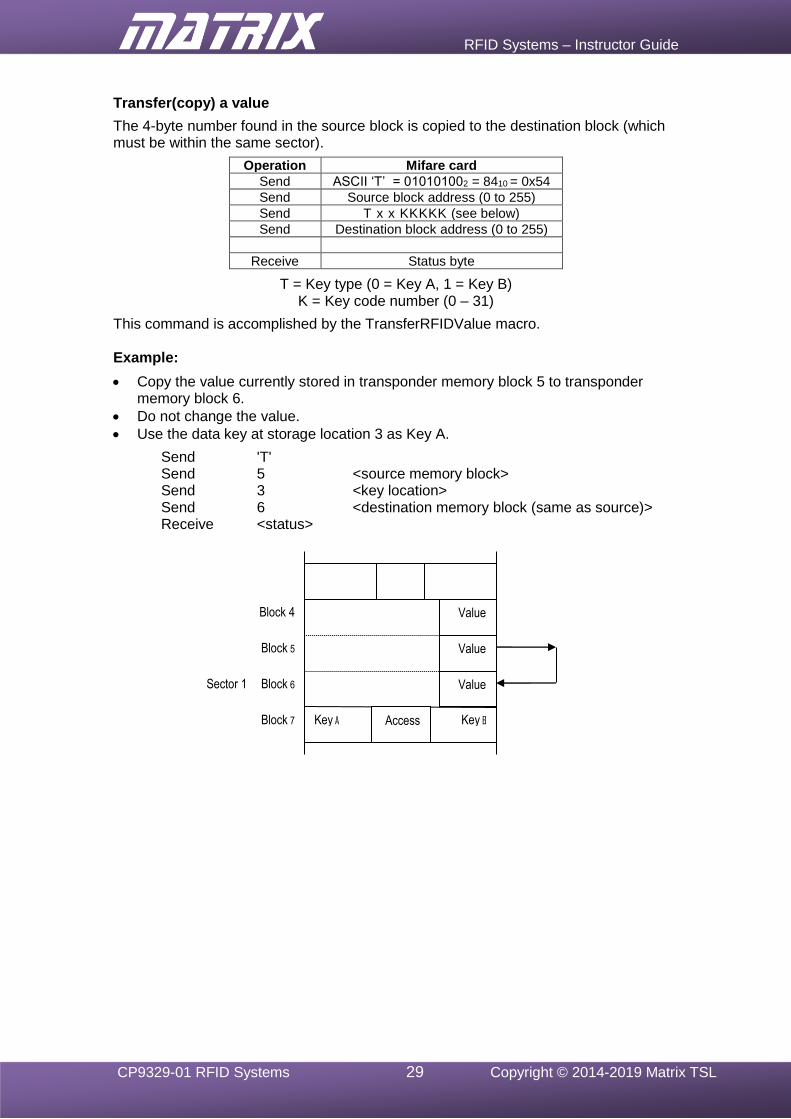
Transfer(copy) a value
The 4-byte number found in the source block is copied to the destination block (which must be within the same sector).
Operation Mifare card
Send ASCII ‘T’ = 010101002 = 8410 = 0x54
Send Source block address (0 to 255)
Send T x x KKKKK (see below)
Send Destination block address (0 to 255)
Receive Status byte
T = Key type (0 = Key A, 1 = Key B) K = Key code number (0 – 31)
This command is accomplished by the TransferRFIDValue macro. Example:
• Copy the value currently stored in transponder memory block 5 to transponder memory block 6.
• Do not change the value.
• Use the data key at storage location 3 as Key A.
Send 'T' Send 5 <source memory block> Send 3 <key location> Send 6 <destination memory block (same as source)> Receive <status>
Block 7
Block 6
Block 5
Block 4
Sector 1
Value
Value
Value
Key A Key B Access
RFID Systems – Instructor Guide
CP9329-01 RFID Systems 30 Copyright © 2014-2019 Matrix TSL
The RS232 protocol RS-232 is a telecommunications standard dating from the 1960’s, defined originally for use in teletypewriters and still in widespread use. For example, it is the basis for data transfer from a computer’s 9-pin serial and 25-pin parallel ports.
It appears in a number of different forms, such as EIA/TIA232, RS-232D, V.24, V.28, X20, and X21. It is used in both asynchronous data transfer and synchronous links such as HDLC, Frame Relay and X.25.
Scope It includes not only electrical specifications, and definitions of the signals used, but also pin outs for a range of connectors such as 9 and 25 pin D-type connectors and RJ45 connectors.
In its native form, voltage levels are -15 to -3V for a 1 (mark), and +3 to +15V for a 0 (space). TTL based RS232 is suitable for short range serial communications at TTL/CMOS logic voltage levels. Converter chips are available to provide an interface between logic level and full RS232 voltage systems (as used in the EB-015 E-blocks2).
Jargon!
Devices which use serial cables for their communication are split into two categories, DCE (Data Communications Equipment) and DTE (Data Terminal Equipment.) Data Communications Equipment includes devices such as an analogue modem, TA adapter (on an ISDN line), CSU/DSU (Channel Service Unit / Data Service Unit – a digital modem, in effect) etc., while Data Terminal Equipment is often a computer or router. Usually, the DCE device controls the flow of data between the DCE and the DTE by providing synchronisation signals or timing signals. The DTE device is also known as the data terminal, whereas the DCE device is the data set.
Confusion can arise over the pin descriptions TD (Transmit Data) and RD (Receive Data). In reality, both pins may ‘transmit’ data and ‘receive’ data at times, depending on whether they are located on the DTE or the DCE device. The solution is to look at these pins from the viewpoint of the DTE device. The DTE device transmits data on the TD line. When the DCE device receives this data, it receives it on the TD line as well! When the modem or CSU/DSU receives data from the outside world and sends it to the DTE, it sends it on the RD line because from the viewpoint of the DTE, the data is being received!
Signalling overview
Data is transmitted and received by the data terminal on pins 2 and 3, (TD and RD) respectively.
The Data Set Ready (DSR) and Data Terminal Ready (DTR) signals become active usually when the respective devices are powered up. They enable these devices to check each other’s status.
Data Carrier Detect (DCD) indicates that a good carrier is being received from a remote modem.
Request To Send (RTS) signal from data terminal and Clear To Send (CTS) signal from the data set are used for flow control. If either device is busy, it can block the arrival of further data by taking the respective signal low. The DTE device can transmit only when it senses that the CTS line is active. When the DTE has finished its transmission, it drops the RTS signal.
The Carrier Detect (CD) and the Ring Indicator (RI) lines are only useful in connections to a modem and telephone line.
RFID Systems – Student Guide
CP9329-01 RFID Systems 1 Copyright © 2014-2019 Matrix TSL
CP9329
RFID Systems
Student Guide
RFID Systems – Student Guide
CP9329-01 RFID Systems 2 Copyright © 2014-2019 Matrix TSL
Contents
1. Introduction to RFID 5 1.1 The RFID system .......................................................................................... 5 1.2 RFID applications .......................................................................................... 6
2. RFID system components 7 2.1 Reader .......................................................................................................... 7 2.2 Transponder .................................................................................................. 7 2.2.1 Passive ............................................................................................................ 7 2.2.2 Semi-active ...................................................................................................... 7 2.2.3 Active ............................................................................................................... 7
3. Anatomy of a passive RFID transponder 8 3.1 Transponder communications ....................................................................... 8 3.2 The structure of a transponder ...................................................................... 9
4. The RFID reader module 11 4.1 Host communications .................................................................................. 11 4.2 Command sequences .................................................................................. 13 4.3 Reader module configuration ....................................................................... 14 4.4 Transponder type selection ......................................................................... 14 4.5 Authorised UID list ....................................................................................... 14
5. The RFID E-blocks2 system configuration 15 5.1 Connecting the RFID E-blocks2 system boards ........................................... 15 5.2 RFID systems exercises E-blocks2 configuration ........................................ 16 5.3 Microcontroller configuration ........................................................................ 16 5.4 Flowcode RFID component ............................................................................... 16
6. Using ICODE mode 17 6.1 Overview ..................................................................................................... 17 6.2 ICODE mode status byte ............................................................................. 17
7. Exercise 1 – Reader module communications in ICODE mode. 18 7.1 Introduction ................................................................................................. 18 7.2 Objective ..................................................................................................... 18 7.3 Requirements .............................................................................................. 18 7.4 The Flowcode program in detail ................................................................. 18 7.4.1 Initialise function .......................................................................................... 18 7.4.2 GetRFIDStatus function ............................................................................... 19 7.5 What to do ................................................................................................... 19 7.6 Further work ................................................................................................ 20
8. Exercise 2 – Obtaining the UID from a transponder in ICODE mode 21 8.1 Introduction ................................................................................................. 21 8.2 Objective ..................................................................................................... 21 8.3 Requirements .............................................................................................. 22 8.4 The Flowcode program in detail ................................................................. 22 8.4.1 GetRFIDUID function ................................................................................... 22 8.4.2 ReadRFIDUID function ................................................................................ 23 8.5 What to do ................................................................................................... 23 8.6 Further work ................................................................................................ 23
9. Exercise 3 – Read transponder data in ICODE mode 24 9.1 Introduction ................................................................................................. 24 9.2 Objective ..................................................................................................... 25 9.3 Requirements .............................................................................................. 25 9.4 The Flowcode program in detail ................................................................. 25 9.4.1 ReadRFIDBlock function ............................................................................. 25 9.4.2 ReadRFIDBuffer function ............................................................................ 26 9.5 What to do ................................................................................................... 26
RFID Systems – Student Guide
CP9329-01 RFID Systems 3 Copyright © 2014-2019 Matrix TSL
9.6 Further work ................................................................................................ 26 10. Exercise 4 – Write transponder data in ICODE mode 27
10.1 Introduction ................................................................................................. 27 10.2 Objective ..................................................................................................... 27 10.3 Requirements .............................................................................................. 27 10.4 The Flowcode program in detail ................................................................. 27 10.4.1 WriteRFIDBuffer function ......................................................................... 27 10.4.2 WriteRFIDBlock function .......................................................................... 28 10.5 What to do ................................................................................................... 28 10.6 Further work ................................................................................................ 29
11. Using Mifare mode 30 11.1 Overview ..................................................................................................... 30 11.2 Mifare mode status byte .............................................................................. 31
12. Exercise 5 – Reader module communications in Mifare mode 32 12.1 Introduction ................................................................................................. 32 12.2 Objective ..................................................................................................... 32 12.3 Requirements .............................................................................................. 32 12.4 The Flowcode program in detail ................................................................. 32 12.4.1 Initialise function ...................................................................................... 33 12.4.2 GetRFIDStatus function ........................................................................... 33 12.5 What to do ................................................................................................... 33 12.6 Further work ................................................................................................ 34
13. Exercise 6 – Obtaining the UID from a Mifare Classic transponder 35 13.1 Introduction ................................................................................................. 35 13.2 Objective ..................................................................................................... 35 13.3 Requirements .............................................................................................. 35 13.4 The Flowcode program in detail ................................................................. 35 13.4.1 GetRFIDUID function ............................................................................... 35 13.4.2 ReadRFIDUID function ............................................................................ 36 13.5 What to do ................................................................................................... 36 13.6 Further work ................................................................................................ 37
14. Exercise 7 – Using security keys 38 14.1 Introduction ................................................................................................. 38 14.1.1 Security features ...................................................................................... 39 14.2 Objective ..................................................................................................... 39 14.3 Requirements .............................................................................................. 40 14.4 The Flowcode program in detail ................................................................. 40 14.4.1 Default Keys ................................................................................................. 40 14.4.2 StoreRFIDKey function ............................................................................ 41 14.4.3 ReadRFIDBlock function ......................................................................... 41 14.5 What to do ................................................................................................... 43 14.6 Further work .................................................................................................... 43
15 Exercise 8 - Write data to a Mifare transponder 44 15.1 Introduction ................................................................................................. 44 15.2 Objective ..................................................................................................... 44 15.3 Requirements .............................................................................................. 44 15.4 The Flowcode program in detail ................................................................. 44 15.4.1 WriteRFIDBuffer function ......................................................................... 45 15.4.2 WriteRFIDBlock function .......................................................................... 45 15.5 What to do ................................................................................................... 45 15.6 Further work ................................................................................................ 46
16. Exercise 9 – Using Value format 47 16.1 Introduction ................................................................................................. 47 16.1.1 The FormatRFIDValue function ............................................................... 47 16.1.2 The IncrementRFIDValue function ........................................................... 48
RFID Systems – Student Guide
CP9329-01 RFID Systems 4 Copyright © 2014-2019 Matrix TSL
16.1.3 The DecrementRFIDValue function ......................................................... 49 16.1.4 The TransferRFIDValue function ............................................................. 50 16.2 Objective ..................................................................................................... 50 16.3 Requirements .............................................................................................. 51 16.4 The Flowcode program in detail ................................................................. 51 16.5 What to do .................................................................................................. 51
RFID Systems – Student Guide
CP9329-01 RFID Systems 5 Copyright © 2014-2019 Matrix TSL
1. Introduction to RFID
1.1 The RFID system
Radio Frequency Identification (RFID) technology has been under development for many years. The recent increase in applications is the result of the development of small, low-cost, low-power, logic devices which can be integrated into inexpensive (or even disposable) transponders (also known as tags).
These logic devices provide the processing power that allows the use of sophisticated communication protocols, permitting the secure transfer of a tag’s identity and data.
On-board memory allows information to be stored in the transponder indefinitely, and changed as required.
The low power consumption of many types of tags allows the entire logic circuit to be powered by electricity generated in the tag’s antenna when it intercepts radio waves transmitted by a reading device. Consequently, these tags do not require any type of internal power supply, such as a battery, decreasing their cost and size, and increasing their operating life almost indefinitely.
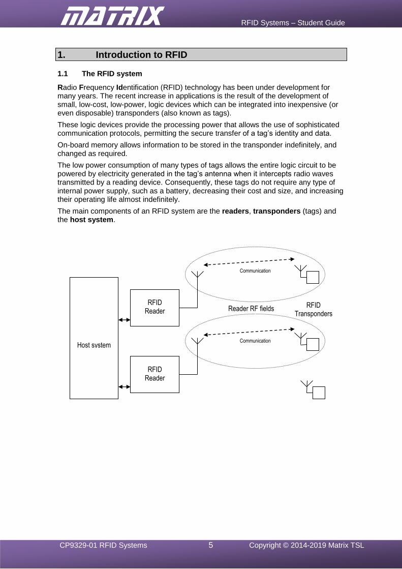
The main components of an RFID system are the readers, transponders (tags) and the host system.
RFID Reader
Host system
RFID Reader
Communication
Reader RF fields
Communication
RFID Transponders
RFID Systems – Student Guide
CP9329-01 RFID Systems 6 Copyright © 2014-2019 Matrix TSL
1.2 RFID applications
The use of broadcast radio frequency signalling means that RFID can work in environments where other systems would have problems such as dirty environments where there is dirt and grease, in bad weather conditions where there is rain, snow and ice, or where there is obscuring substances such as paint that would render barcodes and other optical recognition systems unusable.
RFID applications focus on the task of monitoring the location, movement and identification of objects or people. It is useful because it allows tagged items to be identified and tracked as they move past readers. It works without human intervention and without physical contact between the readers and tags. It does not require line of sight to operate.
Typically, a manufacturer may add a RFID tag to a carton of newly made goods. A RFID-enabled printer can create an adhesive label containing the RFID tag, programmed by the printer, but also showing a bar code and / or text, describing the contents. The carton, and others are then loaded on a pallet to facilitate transport. It is useful to monitor the contents of the pallet throughout its journey to the customer.
Traditionally, this was done either by reading the labels or by scanning the bar codes on each carton. With RFID tags, this process can be automated, allowing inspection at any point by passing the pallet through a RFID-enabled portal, where a RFID reader reads the tags as they pass through. Typically several hundred tags can be read each second, whereas bar-coded items each had to be positioned in front of a scanner.
RFID tags also offer some data storage on the tag itself, whereas barcode technology does not. This enables environmental details such as temperature to be recorded and updated as the tagged goods are transported.
Similarly RFID tags can be added to baggage at airports so that they can be identified and sorted. This monitoring can take place even as the baggage moves at speed down a conveyor belt, using RFID readers on the belt itself.
Large shipping containers, used to transport goods by road, rail and sea, can be monitored in the same way, using RFID techniques that allow communication over longer range, i.e. tens of metres.
‘Chipping’ of dogs and cats, where the RFID device is implanted in the animal, and the use of ear tags in animal husbandry, is used for identification and for the control of automated feeding. Bar-coding is not as durable. The barcode must be stuck to a relatively flat surface on the outside of the object, and is subject to wear-and –tear.
People can be admitted quickly to secured areas by using contactless RFID tags, rather than by using slower techniques such as keypad-operated combination locks.
More sophisticated tags, which can store more data, can be used in ‘e-purse’ applications, such as automatic fare collection on public transport, automatic vending from machines, road toll charging and even gambling.

RFID Systems – Student Guide
CP9329-01 RFID Systems 7 Copyright © 2014-2019 Matrix TSL
2. RFID system components
2.1 Reader
An RFID reader radiates RF (radio frequency) energy from its antenna and attempts to establish communication with any compatible transponders that are detected.
The reader is usually part of a host system that makes use of the data stored in each transponder. Multiple readers can be used to track the movement of transponders from one location to another.
2.2 Transponder
Transponders are grouped into three main types, passive, semi-active and active.
2.2.1 Passive
Passive transponders have no internal power source. When the antenna of a transponder enters the RF field radiated by a reader transmitting at the correct frequency, it absorbs some of the energy. If sufficient energy is absorbed, the control device within the transponder wakes up and attempts to communicate with the reader.
These types of transponders are small, low-cost, and have an almost unlimited life. They can be used in security tags, tickets and product labels. Typical communication range is 0.1-0.4m, though some can be up to 1m.
2.2.2 Semi-active
Semi-active transponders contain a small power source for the logic circuits. The antenna circuit is passive and is only powered when sufficient energy is absorbed from the RF field of a reader. As a result, the life of the internal power source is increased.
These types of transponders are larger and more expensive than the passive transponders, and have a limited life (up to 10 years).
The internal power source allows the transponder to gather data when out of range of a reader. Data could include temperature and shock levels when attached to fragile items during transport.
2.2.3 Active
Active transponders contain a power supply that can allow both the logic circuitry and the transmitter/receiver to be active at all times. This usually allows the transponder to detect weaker signals, and transmit stronger signals than either the passive or semi-active transponders.
These types of transponders are relatively large and expensive.
The improved transmission and reception performance of these types of transponders makes them suitable for tracking and communicating with large objects, like shipping containers, over longer distances than the other types (typically 20-40m).
RFID Systems – Student Guide
CP9329-01 RFID Systems 8 Copyright © 2014-2019 Matrix TSL
3. Anatomy of a passive RFID transponder
3.1 Transponder communications
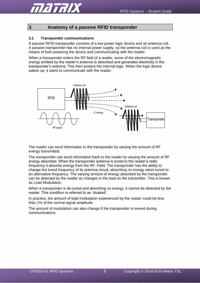
A passive RFID transponder consists of a low power logic device and an antenna coil. A passive transponder has no internal power supply, so the antenna coil is used as the means of both powering the device and communicating with the reader.
When a transponder enters the RF field of a reader, some of the electromagnetic energy emitted by the reader’s antenna is absorbed and generates electricity in the transponder’s antenna. This then powers the internal logic. When the logic device wakes up, it starts to communicate with the reader.
The reader can send information to the transponder by varying the amount of RF energy transmitted.
The transponder can send information back to the reader by varying the amount of RF energy absorbed. When the transponder antenna is tuned to the reader’s radio frequency it absorbs energy from the RF. Field. The transponder has the ability to change the tuned frequency of its antenna circuit, absorbing no energy when tuned to an alternative frequency. The varying amount of energy absorbed by the transponder can be detected by the reader as changes in the load on the transmitter. This is known as Load Modulation.
When a transponder is de-tuned and absorbing no energy, it cannot be detected by the reader. This condition is referred to as ‘cloaked’.
In practice, the amount of load modulation experienced by the reader could be less than 1% of the normal signal amplitude.
The amount of modulation can also change if the transponder is moved during communications.
RFID Reader
Transponder
r.f. energy
RF signal
Antenna coil
Antenna coil
RFID Systems – Student Guide
CP9329-01 RFID Systems 9 Copyright © 2014-2019 Matrix TSL
3.2 The structure of a transponder
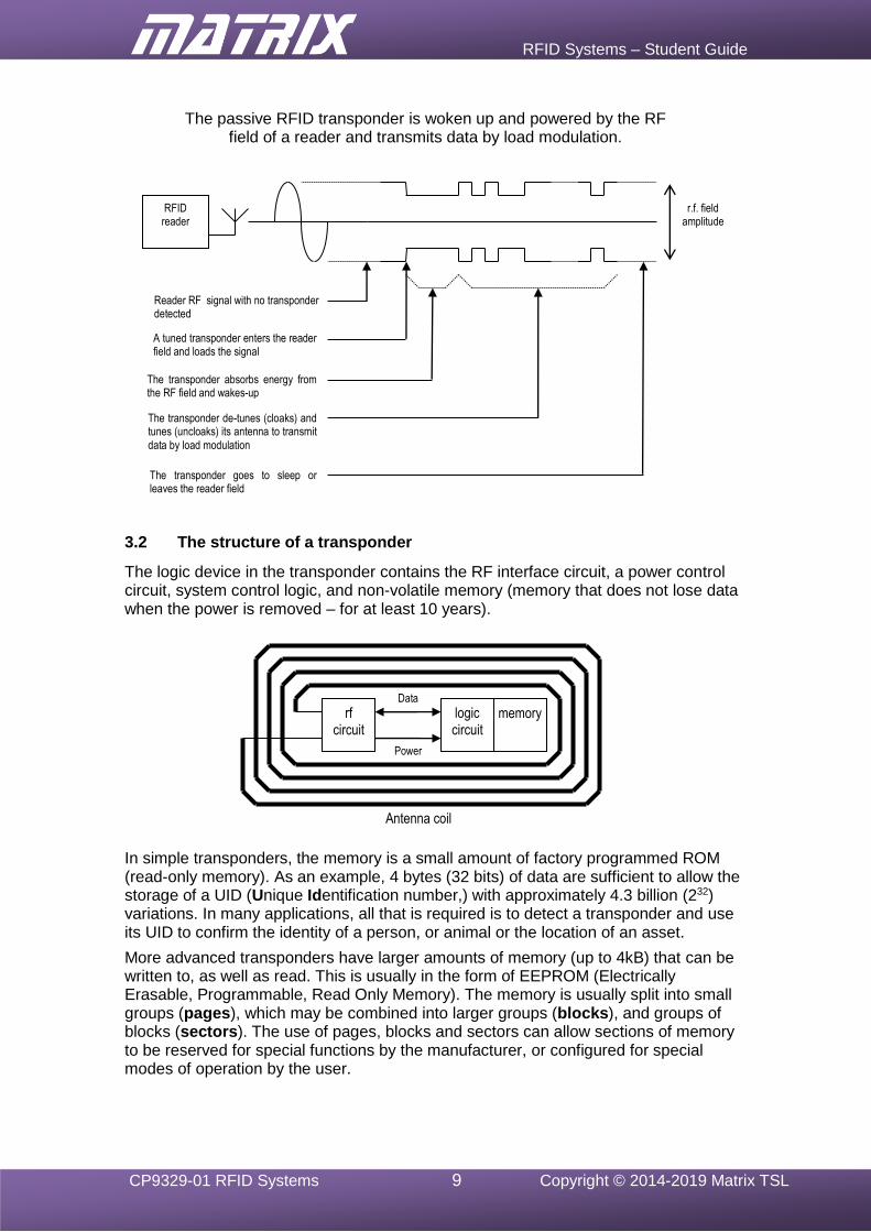
The logic device in the transponder contains the RF interface circuit, a power control circuit, system control logic, and non-volatile memory (memory that does not lose data when the power is removed – for at least 10 years).
In simple transponders, the memory is a small amount of factory programmed ROM (read-only memory). As an example, 4 bytes (32 bits) of data are sufficient to allow the storage of a UID (Unique Identification number,) with approximately 4.3 billion (232) variations. In many applications, all that is required is to detect a transponder and use its UID to confirm the identity of a person, or animal or the location of an asset.
More advanced transponders have larger amounts of memory (up to 4kB) that can be written to, as well as read. This is usually in the form of EEPROM (Electrically Erasable, Programmable, Read Only Memory). The memory is usually split into small groups (pages), which may be combined into larger groups (blocks), and groups of blocks (sectors). The use of pages, blocks and sectors can allow sections of memory to be reserved for special functions by the manufacturer, or configured for special modes of operation by the user.
rf circuit
logic circuit
memory
Antenna coil
Power
Data
A tuned transponder enters the reader field and loads the signal
The transponder absorbs energy from the RF field and wakes-up
Reader RF signal with no transponder detected
The transponder de-tunes (cloaks) and tunes (uncloaks) its antenna to transmit data by load modulation
The transponder goes to sleep or leaves the reader field
The passive RFID transponder is woken up and powered by the RF field of a reader and transmits data by load modulation.
RFID reader
r.f. field amplitude
RFID Systems – Student Guide
CP9329-01 RFID Systems 10 Copyright © 2014-2019 Matrix TSL
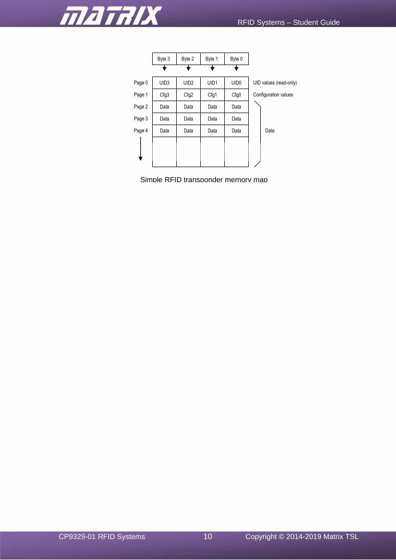
Byte 0 Byte 1 Byte 2 Byte 3
UID values (read-only) UID0 UID1 UID2 UID3
Configuration values
Page 0
Page 1
Page 2
Page 3
Page 4
Cfg3 Cfg2 Cfg1 Cfg0
Data Data Data Data
Data Data Data Data
Data Data Data Data
Simple RFID transponder memory map
Data
RFID Systems – Student Guide
CP9329-01 RFID Systems 11 Copyright © 2014-2019 Matrix TSL
4. The RFID reader module
4.1 Host communications
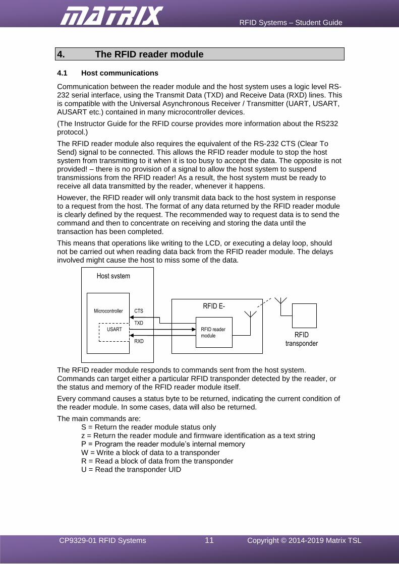
Communication between the reader module and the host system uses a logic level RS-232 serial interface, using the Transmit Data (TXD) and Receive Data (RXD) lines. This is compatible with the Universal Asynchronous Receiver / Transmitter (UART, USART, AUSART etc.) contained in many microcontroller devices.
(The Instructor Guide for the RFID course provides more information about the RS232 protocol.)
The RFID reader module also requires the equivalent of the RS-232 CTS (Clear To Send) signal to be connected. This allows the RFID reader module to stop the host system from transmitting to it when it is too busy to accept the data. The opposite is not provided! – there is no provision of a signal to allow the host system to suspend transmissions from the RFID reader! As a result, the host system must be ready to receive all data transmitted by the reader, whenever it happens.
However, the RFID reader will only transmit data back to the host system in response to a request from the host. The format of any data returned by the RFID reader module is clearly defined by the request. The recommended way to request data is to send the command and then to concentrate on receiving and storing the data until the transaction has been completed.
This means that operations like writing to the LCD, or executing a delay loop, should not be carried out when reading data back from the RFID reader module. The delays involved might cause the host to miss some of the data.
The RFID reader module responds to commands sent from the host system. Commands can target either a particular RFID transponder detected by the reader, or the status and memory of the RFID reader module itself.
Every command causes a status byte to be returned, indicating the current condition of the reader module. In some cases, data will also be returned.
The main commands are: S = Return the reader module status only z = Return the reader module and firmware identification as a text string P = Program the reader module’s internal memory W = Write a block of data to a transponder R = Read a block of data from the transponder
U = Read the transponder UID
USART RFID reader module
TXD
RXD
Microcontroller CTS
Host system
RFID E-blocks2
RFID transponder
RFID Systems – Student Guide
CP9329-01 RFID Systems 12 Copyright © 2014-2019 Matrix TSL
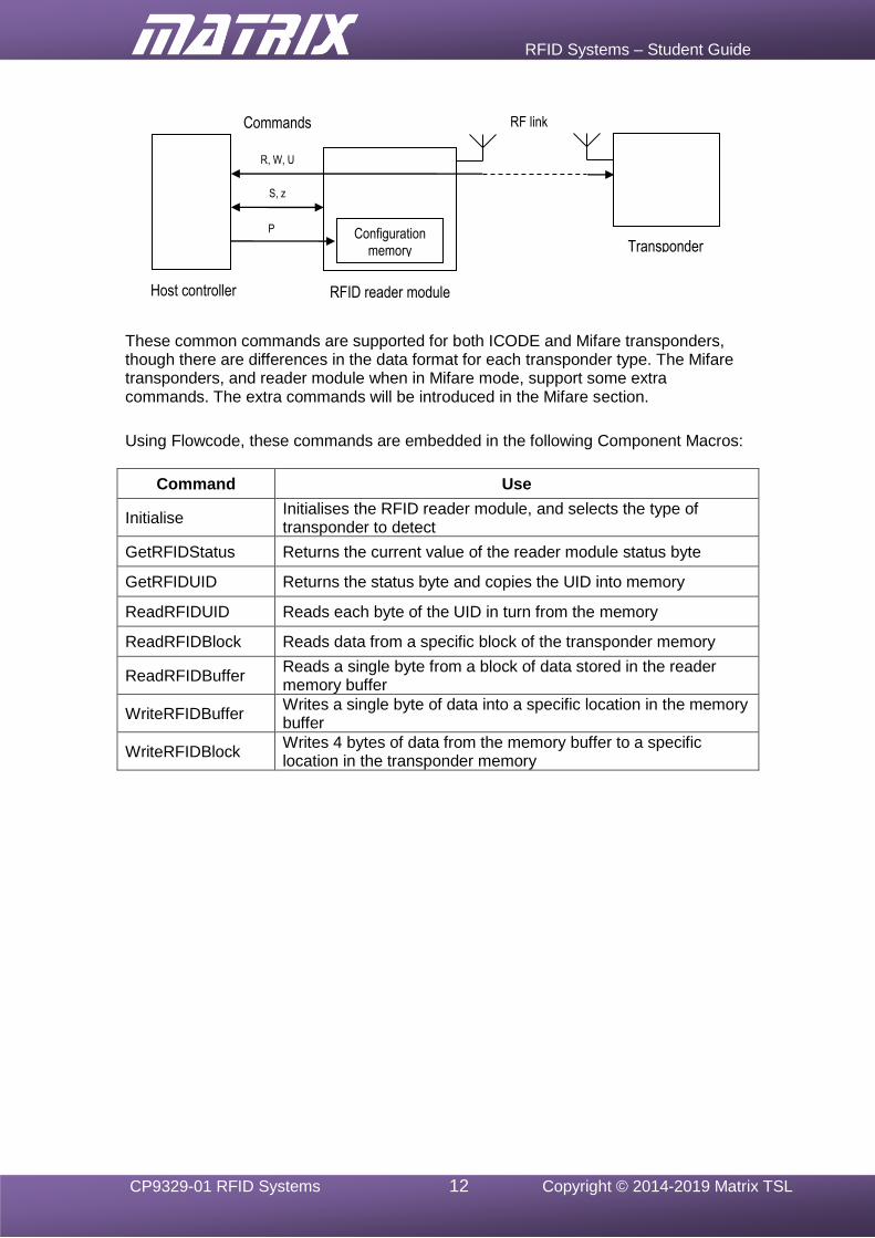
These common commands are supported for both ICODE and Mifare transponders, though there are differences in the data format for each transponder type. The Mifare transponders, and reader module when in Mifare mode, support some extra commands. The extra commands will be introduced in the Mifare section.
Using Flowcode, these commands are embedded in the following Component Macros:
Command Use
Initialise Initialises the RFID reader module, and selects the type of transponder to detect
GetRFIDStatus Returns the current value of the reader module status byte
GetRFIDUID Returns the status byte and copies the UID into memory
ReadRFIDUID Reads each byte of the UID in turn from the memory
ReadRFIDBlock Reads data from a specific block of the transponder memory
ReadRFIDBuffer Reads a single byte from a block of data stored in the reader memory buffer
WriteRFIDBuffer Writes a single byte of data into a specific location in the memory buffer
WriteRFIDBlock Writes 4 bytes of data from the memory buffer to a specific location in the transponder memory
S, z
P Configuration memory
R, W, U
RFID reader module
Commands
Transponder
RF link
Host controller
RFID Systems – Student Guide
CP9329-01 RFID Systems 13 Copyright © 2014-2019 Matrix TSL
4.2 Command sequences
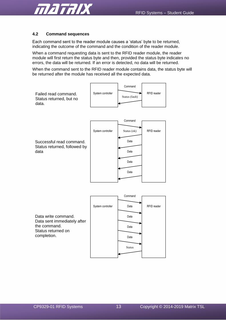
Each command sent to the reader module causes a ‘status’ byte to be returned, indicating the outcome of the command and the condition of the reader module.
When a command requesting data is sent to the RFID reader module, the reader module will first return the status byte and then, provided the status byte indicates no errors, the data will be returned. If an error is detected, no data will be returned.
When the command sent to the RFID reader module contains data, the status byte will be returned after the module has received all the expected data.
Command
Status (fault) System controller RFID reader
Command
Status (ok)
Data
Data
Data
Data
System controller RFID reader
Command
Data
Data
Data
Data System controller RFID reader
Failed read command. Status returned, but no data.
Successful read command. Status returned, followed by data
Data write command. Data sent immediately after the command. Status returned on completion.
Status
RFID Systems – Student Guide
CP9329-01 RFID Systems 14 Copyright © 2014-2019 Matrix TSL
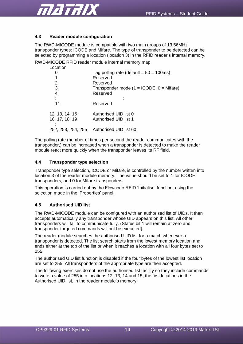
4.3 Reader module configuration
The RWD-MICODE module is compatible with two main groups of 13.56MHz transponder types: ICODE and Mifare. The type of transponder to be detected can be selected by programming a location (location 3) in the RFID reader’s internal memory.
RWD-MICODE RFID reader module internal memory map Location 0 Tag polling rate (default = 50 = 100ms) 1 Reserved 2 Reserved 3 Transponder mode (1 = ICODE, 0 = Mifare) 4 Reserved : : 11 Reserved 12, 13, 14, 15 Authorised UID list 0 16, 17, 18, 19 Authorised UID list 1 : : 252, 253, 254, 255 Authorised UID list 60
The polling rate (number of times per second the reader communicates with the transponder,) can be increased when a transponder is detected to make the reader module react more quickly when the transponder leaves its RF field.
4.4 Transponder type selection
Transponder type selection, ICODE or Mifare, is controlled by the number written into location 3 of the reader module memory. The value should be set to 1 for ICODE transponders, and 0 for Mifare transponders.
This operation is carried out by the Flowcode RFID ‘Initialise’ function, using the selection made in the ‘Properties’ panel.
4.5 Authorised UID list
The RWD-MICODE module can be configured with an authorised list of UIDs. It then accepts automatically any transponder whose UID appears on this list. All other transponders will fail to communicate fully. (Status bit 1 will remain at zero and transponder-targeted commands will not be executed).
The reader module searches the authorised UID list for a match whenever a transponder is detected. The list search starts from the lowest memory location and ends either at the top of the list or when it reaches a location with all four bytes set to 255.
The authorised UID list function is disabled if the four bytes of the lowest list location are set to 255. All transponders of the appropriate type are then accepted.
The following exercises do not use the authorised list facility so they include commands to write a value of 255 into locations 12, 13, 14 and 15, the first locations in the Authorised UID list, in the reader module’s memory.
RFID Systems – Student Guide
CP9329-01 RFID Systems 15 Copyright © 2014-2019 Matrix TSL
5. The RFID E-blocks2 system configuration
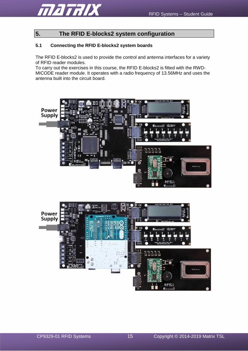
5.1 Connecting the RFID E-blocks2 system boards
The RFID E-blocks2 is used to provide the control and antenna interfaces for a variety of RFID reader modules. To carry out the exercises in this course, the RFID E-blocks2 is fitted with the RWD-MICODE reader module. It operates with a radio frequency of 13.56MHz and uses the antenna built into the circuit board.
RFID Systems – Student Guide
CP9329-01 RFID Systems 16 Copyright © 2014-2019 Matrix TSL
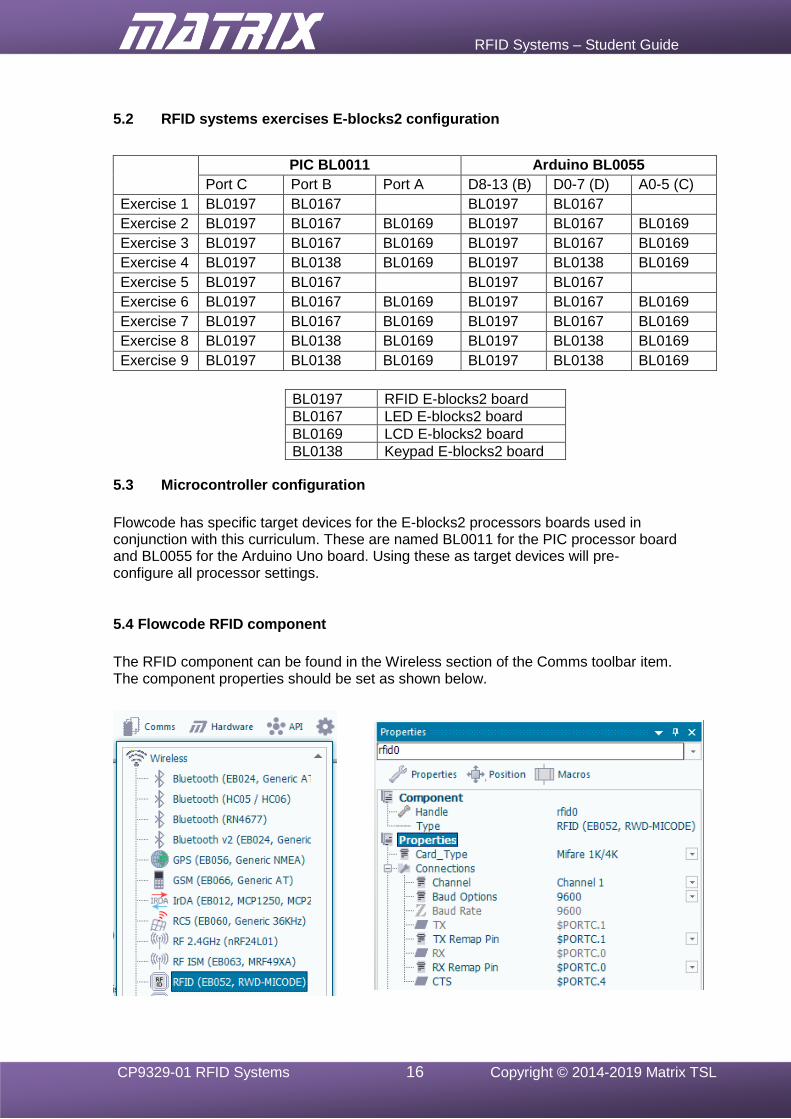
5.2 RFID systems exercises E-blocks2 configuration
PIC BL0011 Arduino BL0055
Port C Port B Port A D8-13 (B) D0-7 (D) A0-5 (C)
Exercise 1 BL0197 BL0167 BL0197 BL0167
Exercise 2 BL0197 BL0167 BL0169 BL0197 BL0167 BL0169
Exercise 3 BL0197 BL0167 BL0169 BL0197 BL0167 BL0169
Exercise 4 BL0197 BL0138 BL0169 BL0197 BL0138 BL0169
Exercise 5 BL0197 BL0167 BL0197 BL0167
Exercise 6 BL0197 BL0167 BL0169 BL0197 BL0167 BL0169
Exercise 7 BL0197 BL0167 BL0169 BL0197 BL0167 BL0169
Exercise 8 BL0197 BL0138 BL0169 BL0197 BL0138 BL0169
Exercise 9 BL0197 BL0138 BL0169 BL0197 BL0138 BL0169
BL0197 RFID E-blocks2 board
BL0167 LED E-blocks2 board
BL0169 LCD E-blocks2 board
BL0138 Keypad E-blocks2 board
5.3 Microcontroller configuration
Flowcode has specific target devices for the E-blocks2 processors boards used in conjunction with this curriculum. These are named BL0011 for the PIC processor board and BL0055 for the Arduino Uno board. Using these as target devices will pre-configure all processor settings.
5.4 Flowcode RFID component
The RFID component can be found in the Wireless section of the Comms toolbar item. The component properties should be set as shown below.
RFID Systems – Student Guide
CP9329-01 RFID Systems 17 Copyright © 2014-2019 Matrix TSL
6. Using ICODE mode
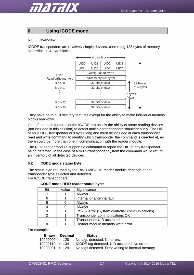
6.1 Overview
ICODE transponders are relatively simple devices, containing 128 bytes of memory accessible in 4-byte blocks.
UID0 UID1 UID2 UID3
UID4 UID5 UID6 UID7
Configuration bytes
Access control bytes
32 bits of data
32 bits of data
4 byte blocks
32 bits of data
32 bits of data
User
Read/Write memory
Block 0
Block 1
Block 26
Block 27
112 bytesof data
32 blocks
of 4 bytes
They have no in-built security features except for the ability to make individual memory blocks read-only.
One of the main features of the ICODE protocol is the ability of some reading devices (not included in this solution) to detect multiple transponders simultaneously. The UID of an ICODE transponder is 8 bytes long and must be included in each transponder read and write command to identify which transponder the command is directed at, as there could be more than one in communication with the reader module.
The RFID reader module supports a command to report the UID of any transponder being detected. In the case of a multi-transponder system the command would return an inventory of all detected devices.
6.2 ICODE mode status byte
The status byte returned by the RWD-MICODE reader module depends on the transponder type selected and detected. For ICODE transponders:
ICODE mode RFID reader status byte:
Bit Value Significance
7 1 Always
6 1 Internal or antenna fault
5 0 Always
4 0 Always
3 1 RS232 error (System controller communications)
2 1 Transponder communications OK
1 1 Transponder UID accepted
0 1 Reader module memory write error 3
For example:
Binary Decimal Status 10000000 = 128 No tags detected. No errors. 10000110 = 134 ICODE tag detected. UID accepted. No errors. 10000001 = 129 No tags detected. Error writing to internal memory.
RFID Systems – Student Guide
CP9329-01 RFID Systems 18 Copyright © 2014-2019 Matrix TSL
7. Exercise 1 – Reader module communications in ICODE mode.
7.1 Introduction
The Flowcode RFID component provides all the functions necessary to control the RWD-MICODE reader module.
These include the Initialise function, which configures the communication link between the host controller and the RFID reader module, and the GetRFIDStatus function, which obtains the current value of the reader module status byte.
With correct configuration, it is possible to detect the presence of a compatible RFID transponder.
7.2 Objective
To design and test a Flowcode program to establish communications between the host controller and the RWD-MICODE reader module by:
• connecting and configuring the system hardware;
• configuring the Flowcode RFID component within a simple Flowcode program;
• writing configuration data to the RFID reader module;
• obtaining and displaying the status information from the RFID reader module.
7.3 Requirements
This exercise requires the following items (see section 5.2 configuration information):
• a microcontroller, either the PIC based BL0011 or Arduino Uno BL0055
• a copy of Flowcode, version 8 or later, running on the PC
• an RFID E-blocks2 (BL0197) with an RWD-MICODE reader module
• an LED E-blocks2 (BL0167)
• an ICODE RFID transponder.
7.4 The Flowcode program in detail
The aim of the program is to:
• Initialise the RFID module using the Initialise function;
• read the module’s status byte repeatedly, using the GetRFIDStatus function;
• display the status byte value on a bank of LEDs connected to Port B to allow the states of the individual bits to be observed easily.
If bits 1 and 2 are both set to 1, a transponder has been detected and communications has been established.
7.4.1 Initialise function
The Initialise function sends the configuration information required to the reader module using the protocol selected in the component properties panel.
The value returned is the reader module status byte generated when the protocol was selected. This can be used to confirm the presence of the RFID reader module and the successful execution of the command.
Expected outcome:
• Bit 7 = 1 Reader present
• Bit 0 = 0 No memory write error

RFID Systems – Student Guide
CP9329-01 RFID Systems 19 Copyright © 2014-2019 Matrix TSL
Bit Value Significance
7 1 Always
6 1 Internal or antenna fault
5 0 Always
4 0 Always
3 1 RS232 error (System controller communications)
2 1 Transponder communications OK
1 1 Transponder UID accepted
0 1 Reader module memory write error
A reminder – ICODE mode RFID reader module status byte:
7.4.2 GetRFIDStatus function
The GetRFIDStatus function causes the reader module to return the current value of the reader module status byte.
This can be used to detect the presence of a matching transponder.
Expected outcome when a transponder is accessed:
• Bit 7 = 1 Reader present
• Bit 2 = 1 Transponder communications OK
• Bit 1 = 1 Transponder UID accepted.
7.5 What to do
1. Write the Flowcode program using the following steps as a guide:
• load the RFID component into a new Flowcode flowchart;
• use the RFID component properties to select the ICODE protocol;
• insert a Component Macro, and select the RFID(0) component and the ‘Initialise’ macro to Initialise the RFID reader module;
• create a program loop that continuously cycles every 100ms (approximately) and uses the RFID component ‘GetRFIDStatus’ to read the status of the RFID reader module;
• write the returned status value to the LED port so that the individual bits can be observed.
2. Compile the program and transfer it to the PIC chip.
3. Run and test the program by observing the LEDs to see if the status byte is displayed both when a RFID card is present, and when no card is present.
4. Do not delete this program as it can be modified for use in exercise 5! The resulting Flowcode program is shown in the next diagram.
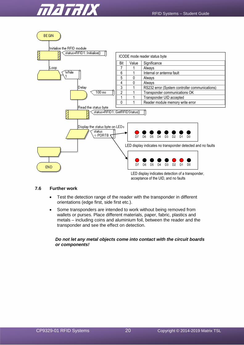
RFID Systems – Student Guide
CP9329-01 RFID Systems 20 Copyright © 2014-2019 Matrix TSL
7.6 Further work
• Test the detection range of the reader with the transponder in different orientations (edge first, side first etc.).
• Some transponders are intended to work without being removed from wallets or purses. Place different materials, paper, fabric, plastics and metals – including coins and aluminium foil, between the reader and the transponder and see the effect on detection.
Do not let any metal objects come into contact with the circuit boards
or components!
ICODE mode reader status byte
Bit Value Significance
7 1 Always
6 1 Internal or antenna fault
5 0 Always
4 0 Always
3 1 RS232 error (System controller communications)
2 1 Transponder communications OK
1 1 Transponder UID accepted
0 1 Reader module memory write error
LED display indicates no transponder detected and no faults
LED display indicates detection of a transponder, acceptance of the UID, and no faults
D7 D6 D5 D4 D3 D2 D1 D0
D7 D6 D5 D4 D3 D2 D1 D0
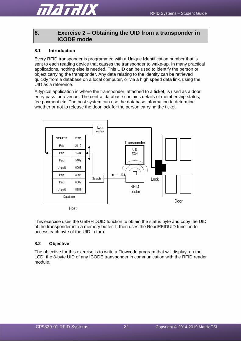
RFID Systems – Student Guide
CP9329-01 RFID Systems 21 Copyright © 2014-2019 Matrix TSL
8. Exercise 2 – Obtaining the UID from a transponder in ICODE mode
8.1 Introduction
Every RFID transponder is programmed with a Unique Identification number that is sent to each reading device that causes the transponder to wake-up. In many practical applications, nothing else is needed. This UID can be used to identify the person or object carrying the transponder. Any data relating to the identity can be retrieved quickly from a database on a local computer, or via a high speed data link, using the UID as a reference.
A typical application is where the transponder, attached to a ticket, is used as a door entry pass for a venue. The central database contains details of membership status, fee payment etc. The host system can use the database information to determine whether or not to release the door lock for the person carrying the ticket.
This exercise uses the GetRFIDUID function to obtain the status byte and copy the UID of the transponder into a memory buffer. It then uses the ReadRFIDUID function to access each byte of the UID in turn.
8.2 Objective
The objective for this exercise is to write a Flowcode program that will display, on the LCD, the 8-byte UID of any ICODE transponder in communication with the RFID reader module.
UID 1234 1234
4096
8888
UID STATUS
Paid
Paid
Paid
Paid
Paid
Unpaid
Unpaid
6502
0003
5489
2112
Lock control
Search
Transponder
RFID reader
Database
1234
Lock
Door
Host system
RFID Systems – Student Guide
CP9329-01 RFID Systems 22 Copyright © 2014-2019 Matrix TSL
8.3 Requirements
This exercise requires the following items (see section 5.2 configuration information):
• a microcontroller, either the PIC based BL0011 or Arduino Uno BL0055
• a copy of Flowcode, version 8 or later, running on the PC
• an RFID E-blocks2 (BL0197) with an RWD-MICODE reader module
• an LED E-blocks2 (BL0167)
• an LCD E-blocks2 (BL0169) • an ICODE RFID transponder (several if possible – make a note of the UIDs).
8.4 The Flowcode program in detail
The program will:
• access the reader module’s status byte using the Initialise function;
• check that a transponder has been detected, and that there are no errors;
• display each of the eight bytes of the transponder UID, in turn, on the LCD display, using the GetRFIDUID function and the ReadRFIDUID function, whenever a transponder has been detected;
• loop back and re-read the status byte repeatedly.
8.4.1 GetRFIDUID function
This causes the reader module to return its status byte and obtain the 8-byte UID of a transponder, if one is available. This 8-byte UID is stored in a memory buffer created by the RFID component. If no transponder is available, or there is a fault, the status byte will indicate this, and so no UID data will be returned. Data transferred between host controller and reader module by this function:
Send ‘U’ ASCII character (decimal value = 85). Receive <status> The value returned is the reader module status
byte. This will indicate when a transponder is accessed successfully.
When the status byte indicates that no transponder is available, or there is an error, the command terminates here. Expected outcome when a transponder is detected, and the UID is transmitted:
• Bit 7 = 1 Reader present
• Bit 2 = 1 Transponder communications ok
• Bit 1 = 1 Transponder UID accepted.
When a transponder is available and there are no faults, the UID data is returned to the reader module.
Receive <UID0> Receive <UID1> Receive <UID2> Receive <UID3> Receive <UID4> Receive <UID5> Receive <UID6> Receive <UID7>
RFID Systems – Student Guide
CP9329-01 RFID Systems 23 Copyright © 2014-2019 Matrix TSL
8.4.2 ReadRFIDUID function
When the GetRFIDUID function is executed successfully, the 8-byte UID of the transponder is stored in a memory buffer created by the RFID component.
The ReadRFIDUID function reads only one of these bytes. The user specifies which byte to retrieve by adding a parameter with a value from 0 to 7. All 8 bytes must be read individually to retrieve the full UID of the transponder being accessed.
8.5 What to do
1. Write the Flowcode program using the following steps as a guide:
• load the RFID component into a new Flowcode flowchart;
• use the RFID component properties to select the ICODE protocol;
• configure the LCD display, using the Start macro;
• Initialise the RFID module by inserting a Component Macro, selecting the RFID(0) component and selecting the ‘Initialise’ macro to Initialise the RFID reader module;
• create a program loop that continuously cycles every 100ms (approximately) and uses the RFID macro GetRFIDUID to keep looking for a transponder, and copying its UID;
• test the value of the returned status byte to determine if a transponder has been detected and valid UID data is available(i.e. status byte value in decimal = 134);
• then use the ReadRFIDUID macro to read each of the 8 UID bytes in turn, and display them on the LCD;
• If a transponder cannot be accessed, clear the LCD display and loop back to repeat the process.
2. Compile the program and transfer it to the PIC chip.
3. Run and test the program by observing the LEDs to see if the status byte is displayed when a RFID card is present.
4. Then examine the LCD to check that the eight-byte UID is displayed when a card is present.
5. Check that the LCD screen is cleared when the card is removed.
6. Do not delete this program as it can be modified for use in exercise 6!
8.6 Further work
• Modify the program to compare the UID of a detected transponder against a list of UIDs. (Do not include the UIDs of all the available transponders in this list, so that some transponders will not be recognised.)
• Remove instruction to display the status byte on the LEDs
• Add Decision icons to test for the list of accepted UIDs.
• If the UID is recognised, light one of the LEDs to indicate a door lock being released.
• If the UID is not recognised, light another LED to indicate a warning alarm.
This program now represents the basis of a practical door entry security system. It could be expanded to include additional data with each UID, to specify for each user, permitted times of entry, and access restrictions to certain zones .
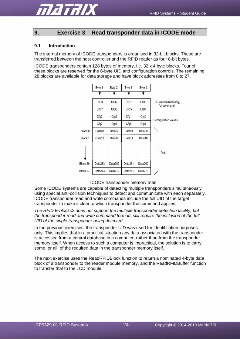
RFID Systems – Student Guide
CP9329-01 RFID Systems 24 Copyright © 2014-2019 Matrix TSL
9. Exercise 3 – Read transponder data in ICODE mode
9.1 Introduction
The internal memory of ICODE transponders is organised in 32-bit blocks. These are transferred between the host controller and the RFID reader as four 8-bit bytes.
ICODE transponders contain 128 bytes of memory, i.e. 32 x 4 byte blocks. Four of these blocks are reserved for the 8-byte UID and configuration controls. The remaining 28 blocks are available for data storage and have block addresses from 0 to 27.
Some ICODE systems are capable of detecting multiple transponders simultaneously using special anti-collision techniques to detect and communicate with each separately. ICODE transponder read and write commands include the full UID of the target transponder to make it clear to which transponder the command applies.
The RFID E-blocks2 does not support the multiple transponder detection facility, but the transponder read and write command formats still require the inclusion of the full UID of the single transponder being detected.
In the previous exercises, the transponder UID was used for identification purposes only. This implies that in a practical situation any data associated with the transponder is accessed from a central database in a computer, rather than from the transponder memory itself. When access to such a computer is impractical, the solution is to carry some, or all, of the required data in the transponder memory itself. The next exercise uses the ReadRFIDBlock function to return a nominated 4-byte data block of a transponder to the reader module memory, and the ReadRFIDBuffer function to transfer that to the LCD module.
Byte 0 Byte 1 Byte 2 Byte 3
UID values (read-only) 'U' command
UID0 UID1 UID2 UID3
Configuration values
Block 0
UID7 UID6 UID5 UID4
Cfg0 Cfg1 Cfg2 Cfg3
Cfg7 Cfg6 Cfg5 Cfg4
Data03 Data02 Data01 Data00
ICODE transponder memory map (128 bytes)
Data
Block 1 Data13 Data12 Data11 Data10
Data272 Data273 Data271 Data270
Data263 Data262 Data261 Data260 Block 26
Block 27
RFID Systems – Student Guide
CP9329-01 RFID Systems 25 Copyright © 2014-2019 Matrix TSL
9.2 Objective
To write a Flowcode program that will:
• detect the presence of a particular ICODE transponder;
• read the transponder’s UID;
• read data from block 5 of the transponder memory;
• display the 4 bytes of data obtained from block 5 on the LCD.
9.3 Requirements
This exercise requires the following items (see section 5.2 configuration information):
• a microcontroller, either the PIC based BL0011 or Arduino Uno BL0055
• a copy of Flowcode, version 8 or later, running on the PC
• an RFID E-blocks2 (BL0197) with an RWD-MICODE reader module
• an LED E-blocks2 (BL0167)
• an LCD E-blocks2 (BL0169)
• an ICODE RFID transponder (several if possible – make a note of the UIDs)
9.4 The Flowcode program in detail
The program will:
• access the reader module’s status byte using the Initialise function;
• check that a transponder has been detected, and that there are no errors, using the GetRFIDUID function;
• copy data from block 5 of the transponder’s data memory to the reader module buffer, using the ReadRFIDBlock function;
• display each of the four bytes of the data, in turn, on the LCD display, using the ReadRFIDBuffer function;
• loop back and repeat the process.
9.4.1 ReadRFIDBlock function
The ReadRFIDBlock function causes the reader module to return its status byte and the 4-byte data block of a transponder, if one is available. If no transponder is available, the supplied UID is incorrect, or there is a fault, the status byte will reflect this condition and no block data will be returned.
Data transferred between the host controller and the reader module by this function:
Send ‘R’ ASCII character (decimal value = 82). Send <block address> 0 to 27 Send <UID0> | Send <UID7> Receive <status>
If the status value indicates that no transponder is available, or there is an error, the command terminates here.
When a transponder is available and there are no faults, the memory block data is returned to the reader module memory.
Receive <data0> | Receive <data3>
Send all eight bytes of the UID
Receive four data bytes.
RFID Systems – Student Guide
CP9329-01 RFID Systems 26 Copyright © 2014-2019 Matrix TSL
9.4.2 ReadRFIDBuffer function
If the ReadRFIDBlock function is executed successfully, the 4 bytes of data from the selected block in the transponder are stored in a memory buffer created by the RFID component. The individual bytes of the data block can then be read using the ReadRFIDBuffer’ function. The function needs to know which of the 4 bytes to read so a value must be provided (0 to 3).
The value returned by this function is the selected byte of the data block. All 4 bytes must be read individually to retrieve the full block of data.
9.5 What to do
1. Write the Flowcode program using the following steps as a guide:
• configure the reader for ICODE mode (as in previous exercises);
• Initialise the LCD display (as in exercise 2);
• Initialise the RFID module using the ‘Initialise’ macro (as in previous exercises);
• use the ‘GetRFIDUID’ macro to attempt to read the UID of a transponder continuously, at 100ms intervals (as in exercise 2);
• use the value of the returned status byte to determine if a transponder has been detected and valid UID data is available (as in exercise 2);
• print “No card detected” until a transponder is detected.
When a transponder is detected:
• use the ReadRFIDBlock macro to read the data from block 5 of the transponder memory, using 5 as the address byte and 0 as the Key_type byte in the parameters – the UID that has been read will be automatically included in the command;
• use the value of the returned status byte to determine if the read command has been executed correctly;
• if the command has not been executed correctly, print “Read error” on the LCD, and loop back to the beginning of the program.
When the ReadRFIDBlock command has been executed successfully:
• use the ReadRFIDBuffer macro to read each of the four data bytes copied from the transponder memory block, and display them on the LCD;
• then return to the main program loop.
(If a transponder has not previously been used it is likely that the block data values will all be 0 or random values.)
2. Compile the program and transfer it to the PIC chip.
3. Run and test the program by observing the LEDs to see if the status byte is displayed when a RFID card is present. Examine the LCD to check that the data is displayed when a card is present.
4. Do not delete this program as it can be modified for use in exercise 7!
9.6 Further work
• Modify the program to read data from other blocks on the transponder card.
• Find out what happens if you try to access a non-existent block.
• Read data from other transponder cards.
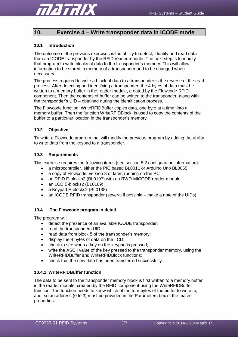
RFID Systems – Student Guide
CP9329-01 RFID Systems 27 Copyright © 2014-2019 Matrix TSL
10. Exercise 4 – Write transponder data in ICODE mode
10.1 Introduction
The outcome of the previous exercises is the ability to detect, identify and read data from an ICODE transponder by the RFID reader module. The next step is to modify that program to write blocks of data to the transponder’s memory. This will allow information to be stored in memory of a transponder and to be changed when necessary.
The process required to write a block of data to a transponder is the reverse of the read process. After detecting and identifying a transponder, the 4 bytes of data must be written to a memory buffer in the reader module, created by the Flowcode RFID component. Then the contents of buffer can be written to the transponder, along with the transponder’s UID – obtained during the identification process.
The Flowcode function, WriteRFIDBuffer copies data, one byte at a time, into a memory buffer. Then the function WriteRFIDBlock, is used to copy the contents of the buffer to a particular location in the transponder’s memory.
10.2 Objective
To write a Flowcode program that will modify the previous program by adding the ability to write data from the keypad to a transponder.
10.3 Requirements
This exercise requires the following items (see section 5.2 configuration information):
• a microcontroller, either the PIC based BL0011 or Arduino Uno BL0055
• a copy of Flowcode, version 8 or later, running on the PC
• an RFID E-blocks2 (BL0197) with an RWD-MICODE reader module
• an LCD E-blocks2 (BL0169)
• a Keypad E-blocks2 (BL0138)
• an ICODE RFID transponder (several if possible – make a note of the UIDs)
10.4 The Flowcode program in detail
The program will:
• detect the presence of an available ICODE transponder;
• read the transponders UID;
• read data from block 5 of the transponder’s memory;
• display the 4 bytes of data on the LCD;
• check to see when a key on the keypad is pressed;
• write the ASCII value of the key pressed to the transponder memory, using the WriteRFIDBuffer and WriteRFIDBlock functions;
• check that the new data has been transferred successfully.
10.4.1 WriteRFIDBuffer function
The data to be sent to the transponder memory block is first written to a memory buffer in the reader module, created by the RFID component using the WriteRFIDBuffer function. The function needs to know which of the four bytes of the buffer to write to, and so an address (0 to 3) must be provided in the Parameters box of the macro properties.
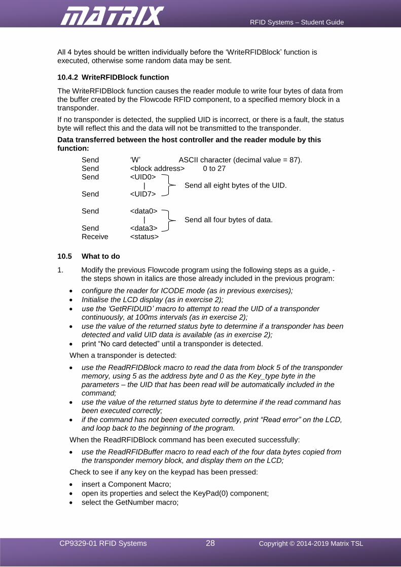
RFID Systems – Student Guide
CP9329-01 RFID Systems 28 Copyright © 2014-2019 Matrix TSL
All 4 bytes should be written individually before the ‘WriteRFIDBlock’ function is executed, otherwise some random data may be sent.
10.4.2 WriteRFIDBlock function
The WriteRFIDBlock function causes the reader module to write four bytes of data from the buffer created by the Flowcode RFID component, to a specified memory block in a transponder.
If no transponder is detected, the supplied UID is incorrect, or there is a fault, the status byte will reflect this and the data will not be transmitted to the transponder.
Data transferred between the host controller and the reader module by this function:
Send ‘W’ ASCII character (decimal value = 87). Send <block address> 0 to 27 Send <UID0> | Send <UID7> Send <data0> | Send <data3> Receive <status>
10.5 What to do
1. Modify the previous Flowcode program using the following steps as a guide, - the steps shown in italics are those already included in the previous program:
• configure the reader for ICODE mode (as in previous exercises);
• Initialise the LCD display (as in exercise 2);
• use the ‘GetRFIDUID’ macro to attempt to read the UID of a transponder continuously, at 100ms intervals (as in exercise 2);
• use the value of the returned status byte to determine if a transponder has been detected and valid UID data is available (as in exercise 2);
• print “No card detected” until a transponder is detected.
When a transponder is detected:
• use the ReadRFIDBlock macro to read the data from block 5 of the transponder memory, using 5 as the address byte and 0 as the Key_type byte in the parameters – the UID that has been read will be automatically included in the command;
• use the value of the returned status byte to determine if the read command has been executed correctly;
• if the command has not been executed correctly, print “Read error” on the LCD, and loop back to the beginning of the program.
When the ReadRFIDBlock command has been executed successfully:
• use the ReadRFIDBuffer macro to read each of the four data bytes copied from the transponder memory block, and display them on the LCD;
Check to see if any key on the keypad has been pressed:
• insert a Component Macro;
• open its properties and select the KeyPad(0) component;
• select the GetNumber macro;
Send all eight bytes of the UID.
Send all four bytes of data.
RFID Systems – Student Guide
CP9329-01 RFID Systems 29 Copyright © 2014-2019 Matrix TSL
• add a decisions box to check when a key has been pressed – i.e. the ‘keyval’ variable, returned by the GetNumber macro, is not 255;
• if no key has been pressed loop back to the beginning of the program.
When a key has been pressed:
• insert a Component Macro;
• open its properties and select the RFID(0) component;
• select the WriteRFIDBuffer macro, and add address ‘0’ and data ‘keyval’ to the Parameters box;
• in the same way, insert three more Component Macros with addresses ‘1’, ‘2’ and ‘3’ respectively, and with data ‘0’ for all three;
• insert another Component Macro for the RFID(0) component;
• select the WriteRFIDBuffer macro, and add address ’5’ and Key_Type ‘0’ to the Properties box, to write the contents of the buffer to block 5 of the transponder memory;
• then return to the main program loop.
2. Compile the program and transfer it to the PIC chip.
3. Run and test the program by:
• observing the LEDs to see if the status byte is displayed when a RFID card is present
• examining the LCD to check that data is displayed when a card is present;
• pressing a key on the keypad and observing that the value of the key is transferred to the transponder memory and then picked up and displayed on the LCD.
4. Do not delete this program as it can be modified for use in exercise 8!
10.6 Further work
• If more than one ICODE transponder is available, introduce each one, in turn, into the reader field to prove that the system is reading and writing the data from each individual tag.
• Create a top-up card system:
• Write a program to display continuously on the LCD, the contents of data block 0, when a transponder is present.
• Top-up the card by pressing a key on the keypad. When this happens, write the value ‘10’ to data block 0 of the transponder memory, and set the value in the other three blocks to ‘0’.
• Whenever the key is not pressed, and the transponder is detected, check whether the value in data block 0 is greater that ‘0’.
• If it is greater than ‘0’, light an led to indicate that the card has been accepted and then decrement the value stored in data block 0.
• If it is equal to ‘0’, light a different led to show that the transponder has been rejected and that another top-up is required.
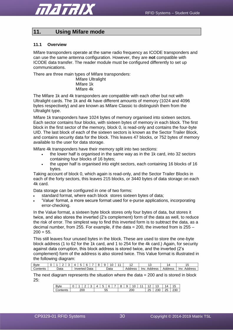
RFID Systems – Student Guide
CP9329-01 RFID Systems 30 Copyright © 2014-2019 Matrix TSL
11. Using Mifare mode
11.1 Overview
Mifare transponders operate at the same radio frequency as ICODE transponders and can use the same antenna configuration. However, they are not compatible with ICODE data transfer. The reader module must be configured differently to set up communications.
There are three main types of Mifare transponders: Mifare Ultralight Mifare 1k Mifare 4k
The Mifare 1k and 4k transponders are compatible with each other but not with Ultralight cards. The 1k and 4k have different amounts of memory (1024 and 4096 bytes respectively) and are known as Mifare Classic to distinguish them from the Ultralight type.
Mifare 1k transponders have 1024 bytes of memory organised into sixteen sectors. Each sector contains four blocks, with sixteen bytes of memory in each block. The first block in the first sector of the memory, block 0, is read-only and contains the four-byte UID. The last block of each of the sixteen sectors is known as the Sector Trailer Block, and contains security data for the block. This leaves 47 blocks, or 752 bytes of memory available to the user for data storage.
Mifare 4k transponders have their memory split into two sections: • the lower half is organised in the same way as in the 1k card, into 32 sectors
containing four blocks of 16 bytes; • the upper half is organised into eight sectors, each containing 16 blocks of 16
bytes. Taking account of block 0, which again is read-only, and the Sector Trailer Blocks in each of the forty sectors, this leaves 215 blocks, or 3440 bytes of data storage on each 4k card.
Data storage can be configured in one of two forms: • standard format, where each block stores sixteen bytes of data; • ‘Value’ format, a more secure format used for e-purse applications, incorporating
error-checking.
In the Value format, a sixteen byte block stores only four bytes of data, but stores it twice, and also stores the inverted (2’s complement) form of the data as well, to reduce the risk of error. The simplest way to find this inverted form is to subtract the data, as a decimal number, from 255. For example, if the data = 200, the inverted from is 255 – 200 = 55.
This still leaves four unused bytes in the block. These are used to store the one-byte block address (1 to 62 for the 1k card, and 1 to 254 for the 4k card.) Again, for security against data corruption, this block address is stored twice, and the inverted (2’s complement) form of the address is also stored twice. This Value format is illustrated in the following diagram:
Byte 0 1 2 3 4 5 6 7 8 9 10 11 12 13 14 15
Contents Data Inverted Data Data Address Inv. Address Address Inv. Address
The next diagram represents the situation where the data = 200 and is stored in block 25:
Byte 0 1 2 3 4 5 6 7 8 9 10 11 12 13 14 15
Contents 200 55 200 25 230 25 230
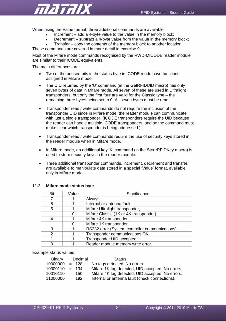
RFID Systems – Student Guide
CP9329-01 RFID Systems 31 Copyright © 2014-2019 Matrix TSL
When using the Value format, three additional commands are available: • Increment – add a 4-byte value to the value in the memory block;
• Decrement – subtract a 4-byte value from the value in the memory block;
• Transfer – copy the contents of the memory block to another location. These commands are covered in more detail in exercise 9.
Most of the Mifare mode commands recognised by the RWD-MICODE reader module are similar to their ICODE equivalents.
The main differences are:
• Two of the unused bits in the status byte in ICODE mode have functions assigned in Mifare mode.
• The UID returned by the ‘U’ command (in the GetRFIDUID macro) has only seven bytes of data in Mifare mode. All seven of these are used in Ultralight transponders, but only the first four are valid for the Classic type – the remaining three bytes being set to 0. All seven bytes must be read!
• Transponder read / write commands do not require the inclusion of the transponder UID since in Mifare mode, the reader module can communicate with just a single transponder. (ICODE transponders require the UID because the reader can handle multiple ICODE transponders, and so the command must make clear which transponder is being addressed.)
• Transponder read / write commands require the use of security keys stored in the reader module when in Mifare mode.
• In Mifare mode, an additional key ‘K’ command (in the StoreRFIDKey macro) is used to store security keys in the reader module.
• Three additional transponder commands, increment, decrement and transfer, are available to manipulate data stored in a special ‘Value’ format, available only in Mifare mode.
11.2 Mifare mode status byte
Bit Value Significance
7 1 Always
6 1 Internal or antenna fault
5 1 Mifare Ultralight transponder,
0 Mifare Classic (1K or 4K transponder)
4 1 Mifare 4K transponder,
0 Mifare 1K transponder
3 1 RS232 error (System controller communications)
2 1 Transponder communications OK
1 1 Transponder UID accepted.
0 1 Reader module memory write error.
Example status values:
Binary Decimal Status 10000000 = 128 No tags detected. No errors. 10000110 = 134 Mifare 1K tag detected, UID accepted. No errors. 10010110 = 150 Mifare 4K tag detected, UID accepted. No errors. 11000000 = 192 Internal or antenna fault (check connections).

RFID Systems – Student Guide
CP9329-01 RFID Systems 32 Copyright © 2014-2019 Matrix TSL
12. Exercise 5 – Reader module communications in Mifare mode
12.1 Introduction
This aim of this exercise is equivalent to that of exercise 1, in the ICODE section. Its purpose is to confirm the correct selection of Mifare mode.
It uses the Initialise and GetRFIDStatus functions to configure the communication link and read the current value of the reader module status byte.
12.2 Objective
To establish communications between the host controller and the RWD-MICODE reader module by:
• connecting and configuring the system hardware;
• configuring the Flowcode RFID component within a simple Flowcode program;
• writing configuration data to the RFID reader module;
• obtaining and displaying the status information from the RFID reader module
12.3 Requirements
This exercise requires the following items (see section 5.2 configuration information):
• a microcontroller, either the PIC based BL0011 or Arduino Uno BL0055
• a copy of Flowcode, version 8 or later, running on the PC
• an RFID E-blocks2 (BL0197) with an RWD-MICODE reader module
• an LED E-blocks2 (BL0167)
• a Mifare RFID transponder.
12.4 The Flowcode program in detail
The aim of the program is to:
• Initialise the RFID module using the Initialise function;
• read the module’s status byte repeatedly, using the GetRFIDStatus function;
• display the status byte value on a bank of LEDs connected to Port B to allow the states of the individual bits to be observed easily.
If bits 1 and 2 are both set to 1, a transponder has been detected and communications has been established.
A reminder:
Bit Value Significance
7 1 Always
6 1 Internal or antenna fault
5 1 Mifare Ultralight transponder,
0 Mifare Classic (1K or 4K transponder)
4 1 Mifare 4K transponder,
0 Mifare 1K transponder
3 1 RS232 error (System controller communications)
2 1 Transponder communications OK
1 1 Transponder UID accepted.
0 1 Reader module memory write error.

RFID Systems – Student Guide
CP9329-01 RFID Systems 33 Copyright © 2014-2019 Matrix TSL
12.4.1 Initialise function
The Initialise function sends the configuration information required to the reader module using the protocol selected in the component properties panel.
The value returned is the reader module status byte generated when the protocol was selected. This can be used to confirm the presence of the RFID reader module and the successful execution of the command.
Expected outcome:
• Bit 7 = 1 Reader present
• Bit 0 = 0 No memory write error
12.4.2 GetRFIDStatus function
The GetRFIDStatus function causes the reader module to return the current value of the reader module status byte.
This can be used to detect the presence of a matching transponder.
Expected outcome when a transponder is accessed:
• Bit 7 = 1 Reader present
• Bit 2 = 1 Transponder communications OK
• Bit 1 = 1 Transponder UID accepted.
12.5 What to do
1. Write the Flowcode program using the following steps as a guide:
• load the RFID component into a new Flowcode flowchart;
• use the RFID component properties to select the Mifare protocol;
• insert a Component Macro, and select the RFID(0) component and the ‘Initialise’ macro to Initialise the RFID reader module;
• create a program loop that continuously cycles every 100ms (approximately) and uses the RFID component ‘GetRFIDStatus’ to read the status of the RFID reader module;
• write the returned status value to the LEDs on Port B so that the individual bits can be observed.
(Alternatively, the program written in exercise 1 can be modified by changing the RFID component properties to the Mifare protocol.)
2. Compile the program and transfer it to the PIC chip.
3. Run and test the program by observing the LEDs to see if the status byte is displayed both when a Mifare card is present, and when no card is present.
The resulting Flowcode program is shown in the next diagram.
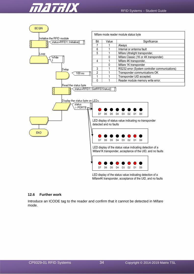
RFID Systems – Student Guide
CP9329-01 RFID Systems 34 Copyright © 2014-2019 Matrix TSL
12.6 Further work
Introduce an ICODE tag to the reader and confirm that it cannot be detected in Mifare mode.
Mifare mode reader module status byte
Bit Value Significance
7 1 Always
6 1 Internal or antenna fault
5 1 Mifare Ultralight transponder,
0 Mifare Classic (1K or 4K transponder)
4 1 Mifare 4K transponder,
0 Mifare 1K transponder
3 1 RS232 error (System controller communications)
2 1 Transponder communications OK
1 1 Transponder UID accepted.
0 1 Reader module memory write error.
LED display of status value indicating no transponder detected and no faults
LED display of the status value indicating detection of a Mifare1K transponder, acceptance of the UID, and no faults
LED display of the status value indicating detection of a Mifare4K transponder, acceptance of the UID, and no faults
D7 D6 D5 D4 D3 D2 D1 D0
D7 D6 D5 D4 D3 D2 D1 D0
D7 D6 D5 D4 D3 D2 D1 D0
RFID Systems – Student Guide
CP9329-01 RFID Systems 35 Copyright © 2014-2019 Matrix TSL
13. Exercise 6 – Obtaining the UID from a Mifare Classic transponder
13.1 Introduction
The value of the reader module status byte returned when a Mifare Classic transponder is detected depends on the size of the transponder data memory available.
Mifare 1K = 134 (Bit 4 of the status byte = 0) Mifare 4K = 150 (Bit 4 of the status byte = 1)
If either of these values is returned in the status byte, a transponder is available and the UID can be read. The UID is not required to be included in any of the data read / write commands because Mifare mode cannot handle more than one transponder at a time.
13.2 Objective
The objective for this exercise is to write a Flowcode program that will display, on the LCD, the 8-byte UID of any Mifare transponder in communication with the RFID reader module.
13.3 Requirements
This exercise requires the following items (see section 5.2 configuration information):
• a microcontroller, either the PIC based BL0011 or Arduino Uno BL0055
• a copy of Flowcode, version 8 or later, running on the PC
• an RFID E-blocks2 (BL0197) with an RWD-MICODE reader module
• an LED E-blocks2 (BL0167)
• an LCD E-blocks2 (BL0169) • a Mifare RFID transponder (several if possible – make a note of the UIDs).
13.4 The Flowcode program in detail
The program will:
• access the reader module’s status byte using the Initialise function;
• check that a transponder has been detected, and that there are no errors;
• display each byte of the transponder 4-byte UID, in turn, on the LCD display, using the GetRFIDUID function and the ReadRFIDUID function, whenever a transponder has been detected;
• loop back and re-read the status byte repeatedly.
13.4.1 GetRFIDUID function
This function causes the reader module to return seven bytes of UID data from a transponder. If no transponders are present, or there is a fault, the status byte will indicate this, and so no data will be returned. The seven UID bytes are required for compatibility with Ultralight transponders. Classic transponders only use four bytes so the reader module sets the remaining three bytes to 0.
RFID Systems – Student Guide
CP9329-01 RFID Systems 36 Copyright © 2014-2019 Matrix TSL
Data transferred between host controller and reader module by this function:
Send ‘U’ ASCII character (decimal value = 85). Receive <status> The value returned is the reader module status
byte. This will indicate when a transponder is accessed successfully.
When the status value indicates that no transponder is available, or there is an error, the command terminates here.
When a transponder is detected and there are no faults, the UID data is returned.
Receive <UID0> Receive <UID1> Receive <UID2> Receive <UID3> Receive <UID4> 0 for Mifare Classic transponders Receive <UID5> 0 for Mifare Classic transponders Receive <UID6> 0 for Mifare Classic transponders
Example:
Before and after a Mifare 1K transponder is detected:
Send ‘U’ Receive 128 Status value indicates no transponder available.
Send ‘U’ Receive 134 Mifare 1K transponder is now available. Receive <UID0> Receive <UID1> Receive <UID2> Receive <UID3> Receive 0 Receive 0 Receive 0
13.4.2 ReadRFIDUID function
When the GetRFIDUID function is executed successfully, the seven-byte UID of the transponder is stored in a memory buffer created by the RFID component.
The ReadRFIDUID function reads only one of these bytes. The user specifies which byte to retrieve by adding a parameter with a value from 0 to 3.
13.5 What to do
1. Either write the Flowcode program using the following steps as a guide or modify the program from exercise 2, by ignoring the sections in italics:
• load the RFID component into a new Flowcode flowchart;
• use the RFID component properties to select the Mifare protocol;
• configure the LCD display, using the Start macro;
• Initialise the RFID module by inserting a Component Macro, selecting the RFID(0) component and selecting the ‘Initialise’ macro to Initialise the RFID reader module;
• create a program loop that continuously cycles every 100ms (approximately) and uses the RFID macro GetRFIDUID to keep looking for a transponder, and copying its UID;
• test the value of the returned status byte to determine if a transponder has been detected and valid UID data is available
RFID Systems – Student Guide
CP9329-01 RFID Systems 37 Copyright © 2014-2019 Matrix TSL
• then use the ReadRFIDUID macro to read each of the four UID bytes in turn, and display them on the LCD;
• If a transponder cannot be accessed, clear the LCD display and loop back to repeat the process.
2. Compile the program and transfer it to the PIC chip.
3. Run and test the program by observing the LEDs to see if the status byte is displayed when a RFID card is present.
4. Then examine the LCD to check that the four-byte UID is displayed when a card is present.
5. Check that the LCD screen is cleared when the card is removed.
13.6 Further work
• Obtain the UID from a series of Mifare cards. Make a note of these for future use.
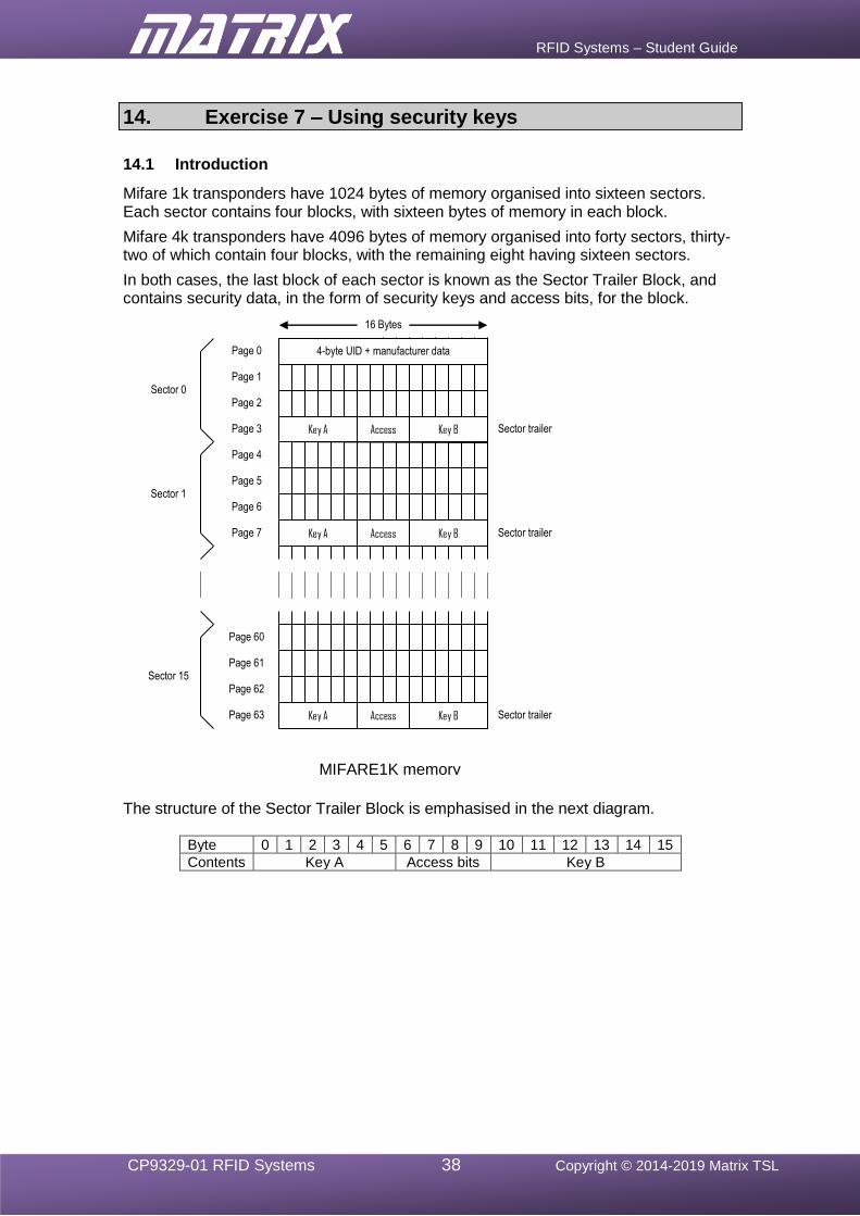
RFID Systems – Student Guide
CP9329-01 RFID Systems 38 Copyright © 2014-2019 Matrix TSL
14. Exercise 7 – Using security keys
14.1 Introduction
Mifare 1k transponders have 1024 bytes of memory organised into sixteen sectors. Each sector contains four blocks, with sixteen bytes of memory in each block.
Mifare 4k transponders have 4096 bytes of memory organised into forty sectors, thirty-two of which contain four blocks, with the remaining eight having sixteen sectors.
In both cases, the last block of each sector is known as the Sector Trailer Block, and contains security data, in the form of security keys and access bits, for the block.
The structure of the Sector Trailer Block is emphasised in the next diagram.
Byte 0 1 2 3 4 5 6 7 8 9 10 11 12 13 14 15
Contents Key A Access bits Key B
Key A Key B Access
Key A Key B Access
Key A Key B Access
Page 0
Page 1
Page 2
Page 3
Page 4
Page 5
Page 6
Page 7
Page 60
Page 61
Page 62
Page 63
16 Bytes
4-byte UID + manufacturer data
Sector trailer
Sector trailer
Sector trailer
Sector 0
Sector 1
Sector 15
MIFARE1K memory map
RFID Systems – Student Guide
CP9329-01 RFID Systems 39 Copyright © 2014-2019 Matrix TSL
14.1.1 Security features
Mifare transponders contain security features that control access to sectors of memory by means of two security keys and accompanying access rules.
The keys, known as Key A and Key B, are each six bytes in length. The access rules define which key must be used to perform read / write commands on each block of memory. The options controlled by the access bits are:
• access to a block is read / write; • access to a block is read only; • access to a block is write only; • data is stored in standard data or Value format; • use Key A and / or Key B for access.
Every transponder command must be accompanied by the correct key. Access can require the following conditions:
• the use of Key A only; • the use of Key B only; • the use of either of Key A or Key B.
or access can be denied regardless of which key is used.
In the final case, the selected command cannot be executed on that block of memory. These access conditions are set separately for each of the commands – Read, Write, Increment, Decrement and Transfer. A data block can be made 'read-only' by preventing the use of the Write command.
Mifare 1k cards and blocks in the lower half of 4k cards can have different access conditions set for each block. For the upper half of 4k cards, conditions are set for groups of five blocks. The access control bits themselves can also be protected, by preventing any write commands to their own block. The effect of this is permanent and must be carefully planned. (It will not form part of these exercises!)
The RWD-MICODE reader module contains a memory array that allows up to 32 6-byte keys to be stored. Each transponder read/write command must include the array index for the key being used, and a flag to indicate whether the key is to be used as Key A or Key B.
The requested operation will be allowed only if:
• the key being addressed in the reader module matches the equivalent key in the transponder for the sector being addressed.
• the access bits allow the requested operation to be performed using the supplied key.
The next exercise uses the StoreRFIDKey function to create a new key value. The ReadRFIDBlock function and the ReadRFIDBuffer functions are used to transfer data from the transponder memory to the reader module memory buffer, and from there, transfer it to the LCD display.
14.2 Objective
To design and test a Flowcode program that will demonstrate the use of security keys to access data from a Mifare transponder. When the correct key is used, data will be read from block 5 of the transponder’s memory, and displayed on the LCD.
RFID Systems – Student Guide
CP9329-01 RFID Systems 40 Copyright © 2014-2019 Matrix TSL
14.3 Requirements
This exercise requires the following items (see section 5.2 configuration information):
• a microcontroller, either the PIC based BL0011 or Arduino Uno BL0055
• a copy of Flowcode, version 8 or later, running on the PC
• an RFID E-blocks2 (BL0197) with an RWD-MICODE reader module
• an LED E-blocks2 (BL0167)
• an LCD E-blocks2 (BL0169)
• a Mifare RFID transponder.
14.4 The Flowcode program in detail
The program will:
• run the RFID reader module in Mifare mode;
• write new security key values to the reader module key storage array, using the StoreRFIDKey function;
• attempt to read data continuously from block 5 of a Mifare transponder, using the ReadRFIDBlock function and display the returned status byte on the LEDs, using the ReadRFIDBuffer command;
• display the status byte values under the following conditions:
• no card present;
• card present, but using the incorrect key value;
• card present, and using the correct key value;
• display the current key location on the LCD when a read command is completed successfully.
14.4.1 Default Keys
Mifare transponders are supplied by the manufacturers with default (transport) setting for all the keys and access bits. These settings allow full access, (read and write access) to the memory using key A for each operation.
Incorrect reprogramming of a sector trailer block can cause the sector to become permanently unusable, so this exercise will demonstrate the basic security features by changing the corresponding settings in the reader module, rather than in the transponder card itself.
The transport key settings depend on the manufacturer of the Mifare transponde. The most common values are:
Key A 160, 161, 162, 163, 164, 165 (0xA0, 0xA1, 0xA2, 0xA3, 0xA4, 0xA5 in hexadecimal) Key B 176, 177, 178, 179, 180, 181 (0xB0, 0xB1, 0xB2, 0xB3, 0xB4, 0xB5 in hexadecimal)
or
Key A 255, 255, 255, 255, 255, 255 (0xFF, 0xFF, 0xFF, 0xFF, 0xFF, 0xFF in hexadecimal) Key B 255, 255, 255, 255, 255, 255 (0xFF, 0xFF, 0xFF, 0xFF, 0xFF, 0xFF in hexadecimal)
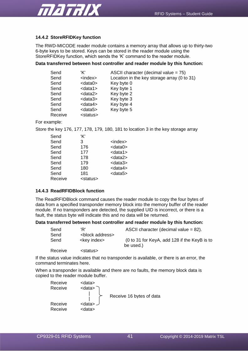
RFID Systems – Student Guide
CP9329-01 RFID Systems 41 Copyright © 2014-2019 Matrix TSL
14.4.2 StoreRFIDKey function
The RWD-MICODE reader module contains a memory array that allows up to thirty-two 6-byte keys to be stored. Keys can be stored in the reader module using the StoreRFIDKey function, which sends the ‘K’ command to the reader module.
Data transferred between host controller and reader module by this function:
Send 'K' ASCII character (decimal value = 75) Send <index> Location in the key storage array (0 to 31) Send <data0> Key byte 0 Send <data1> Key byte 1 Send <data2> Key byte 2 Send <data3> Key byte 3 Send <data4> Key byte 4 Send <data5> Key byte 5 Receive <status>
For example:
Store the key 176, 177, 178, 179, 180, 181 to location 3 in the key storage array
Send 'K' Send 3 <index> Send 176 <data0> Send 177 <data1> Send 178 <data2> Send 179 <data3> Send 180 <data4> Send 181 <data5> Receive <status>
14.4.3 ReadRFIDBlock function
The ReadRFIDBlock command causes the reader module to copy the four bytes of data from a specified transponder memory block into the memory buffer of the reader module. If no transponders are detected, the supplied UID is incorrect, or there is a fault, the status byte will indicate this and no data will be returned.
Data transferred between host controller and reader module by this function:
Send 'R' ASCII character (decimal value = 82). Send <block address> Send <key index> (0 to 31 for KeyA, add 128 if the KeyB is to
be used.) Receive <status>
If the status value indicates that no transponder is available, or there is an error, the command terminates here.
When a transponder is available and there are no faults, the memory block data is copied to the reader module buffer.
Receive <data> Receive <data> | | Receive <data> Receive <data>
Receive 16 bytes of data
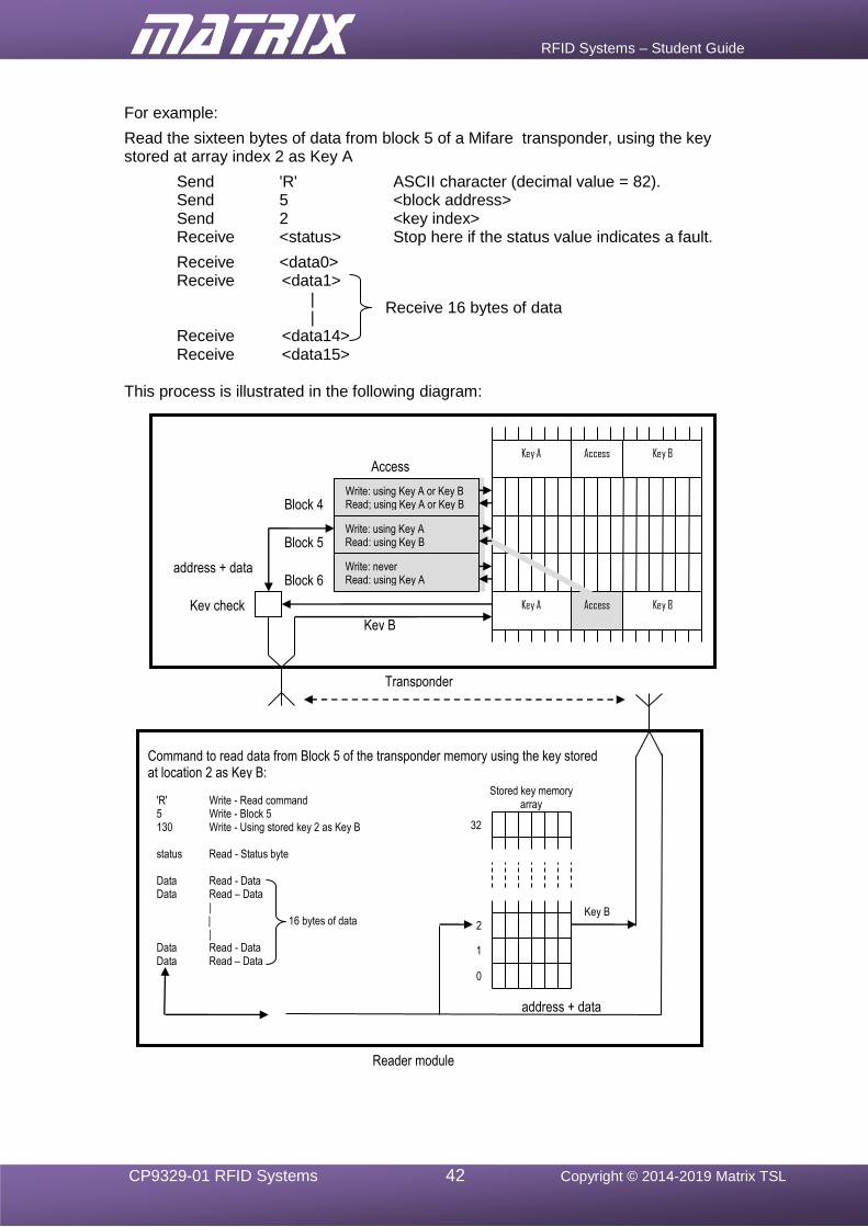
RFID Systems – Student Guide
CP9329-01 RFID Systems 42 Copyright © 2014-2019 Matrix TSL
For example:
Read the sixteen bytes of data from block 5 of a Mifare transponder, using the key stored at array index 2 as Key A
Send 'R' ASCII character (decimal value = 82). Send 5 <block address> Send 2 <key index> Receive <status> Stop here if the status value indicates a fault.
Receive <data0> Receive <data1> | | Receive <data14> Receive <data15>
This process is illustrated in the following diagram:
Key A Access Key B
Key A Access Key B
0
1
2
32
'R' Write - Read command 5 Write - Block 5 130 Write - Using stored key 2 as Key B status Read - Status byte Data Read - Data Data Read – Data | | 16 bytes of data | Data Read - Data Data Read – Data
Command to read data from Block 5 of the transponder memory using the key stored at location 2 as Key B:
Block 4
Block 5
Block 6
address + data
Key B
Key B
address + data
Stored key memory array
Access control
Key check
Transponder
Write: using Key A or Key B Read; using Key A or Key B
Write: using Key A Read: using Key B
Write: never Read: using Key A
Receive 16 bytes of data
Reader module

RFID Systems – Student Guide
CP9329-01 RFID Systems 43 Copyright © 2014-2019 Matrix TSL
14.5 What to do
Either write the Flowcode program using the following steps as a guide or modify the program from exercise 3, by ignoring the sections in italics:
1. Write the Flowcode program using the following steps as a guide:
• configure the reader for Mifare mode;;
• Initialise the LCD display;
• Initialise the RFID module using the 'Initialise' macro;
• insert two Component Macros, for the RFID(0) module, each using a StoreRFIDKey macro, the first to write the key 0xff, 0xff, 0xff, 0xff, 0xff, 0xff to key storage array location 0, and the second to write key 0xa0, 0xa1, 0xa2, 0xa3, 0xa4, 0xa5 to key storage array location 2;
• use the 'GetRFIDUID' macro to attempt to read the UID of a transponder continuously, at 100ms intervals;
• use the value of the returned status byte to determine if a transponder has been detected and valid UID data is available;
• print “No card detected” until a transponder is detected.
When a transponder is detected:
• use the ReadRFIDBlock macro to read the data from block 5 of the transponder memory, using 5 as the address byte and 0 as the Key_type byte in the parameters;
• use the value of the returned status byte to determine if the read command has been executed correctly;
• if the command has not been executed correctly, print “Read error” on the LCD, and loop back to the beginning of the program.
When the ReadRFIDBlock command has been executed successfully:
• use the ReadRFIDBuffer macro to read each of the four data bytes copied from the transponder memory block, and display them on the LCD;
• then return to the main program loop.
2. Compile the program and transfer it to the PIC chip.
3. Run and test the program by observing the LEDs to see if the status byte is displayed when a Mifare RFID card is present. Examine the LCD to check that the data is displayed when a card is present.
14.6 Further work
• Modify the program to read data from other blocks on the transponder card.
• Find out what happens if you use an incorrect 6-byte key to access the card.

RFID Systems – Student Guide
CP9329-01 RFID Systems 44 Copyright © 2014-2019 Matrix TSL
15 Exercise 8 - Write data to a Mifare transponder
15.1 Introduction
So far, the Mifare mode exercises have looked at the issues involved in detecting, identify and read data from an Mifare transponder by the RFID reader module. The next step is to modify that program to write blocks of data to the transponder's memory. This will allow information to be stored in memory of a transponder and to be changed when necessary.
As for the ICODE transponder in exercise 4, the process required to write a block of data to a transponder is the reverse of the read process. After detecting and identifying a transponder, the 4 bytes of data must be written to a memory buffer in the reader module, created by the Flowcode RFID component. Then the contents of buffer can be written to the transponder, along with the transponder's UID - obtained during the identification process.
The Flowcode function, WriteRFIDBuffer copies data, one byte at a time, into a memory buffer. Then the function WriteRFIDBlock, is used to copy the contents of the buffer to a particular location in the transponder’s memory.
15.2 Objective
To write a Flowcode program that will modify the previous program by adding the ability to write data from the keypad to a Mifare transponder.
15.3 Requirements
This exercise requires the following items (see section 5.2 configuration information):
• a microcontroller, either the PIC based BL0011 or Arduino Uno BL0055
• a copy of Flowcode, version 8 or later, running on the PC
• an RFID E-blocks2 (BL0197) with an RWD-MICODE reader module
• a Keypad E-blocks2 (BL0138)
• an LCD E-blocks2 (BL0169) • a Mifare RFID transponder (several if possible – make a note of the UIDs).
15.4 The Flowcode program in detail
The program overview is exactly the same as in exercise 4, for the ICODE transponder. It will:
• detect the presence of a Mifare transponder;
• read the transponders UID;
• read data from block 5 of the transponder’s memory;
• display the 4 bytes of data on the LCD;
• check to see when a key on the keypad is pressed;
• write the ASCII value of the key pressed to the transponder memory, using the WriteRFIDBuffer and WriteRFIDBlock functions;
• check that the new data has been transferred successfully.
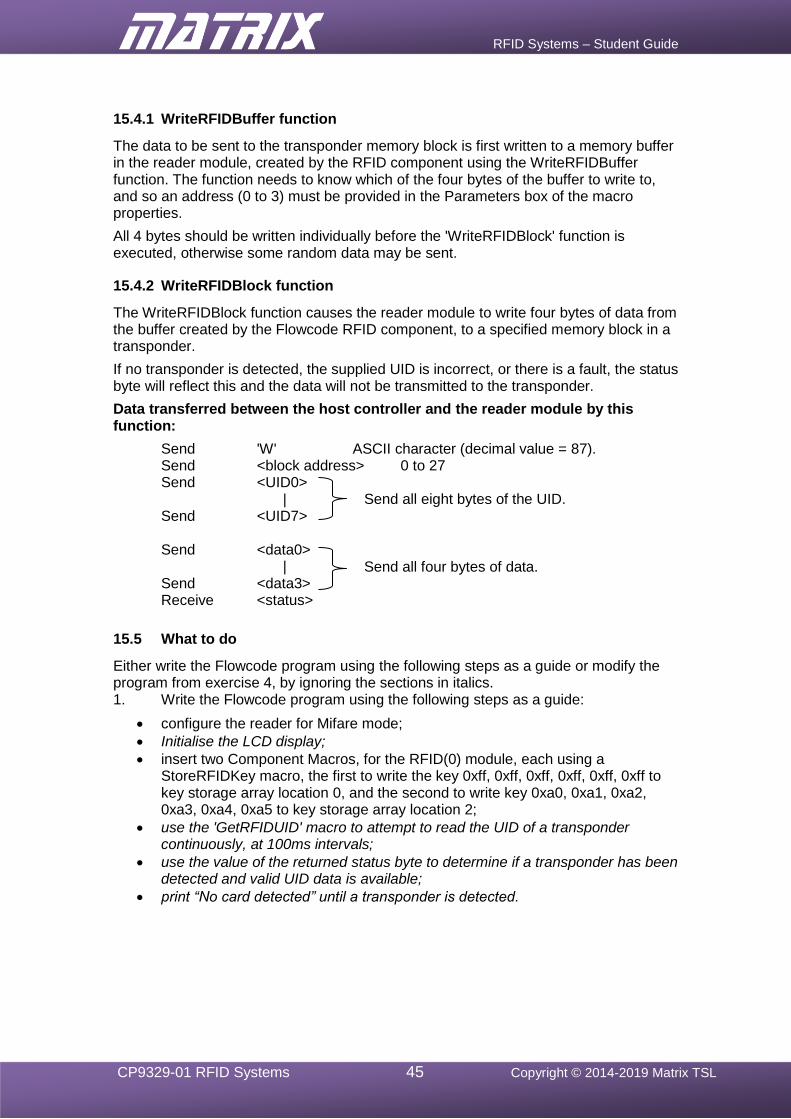
RFID Systems – Student Guide
CP9329-01 RFID Systems 45 Copyright © 2014-2019 Matrix TSL
15.4.1 WriteRFIDBuffer function
The data to be sent to the transponder memory block is first written to a memory buffer in the reader module, created by the RFID component using the WriteRFIDBuffer function. The function needs to know which of the four bytes of the buffer to write to, and so an address (0 to 3) must be provided in the Parameters box of the macro properties.
All 4 bytes should be written individually before the 'WriteRFIDBlock' function is executed, otherwise some random data may be sent.
15.4.2 WriteRFIDBlock function
The WriteRFIDBlock function causes the reader module to write four bytes of data from the buffer created by the Flowcode RFID component, to a specified memory block in a transponder.
If no transponder is detected, the supplied UID is incorrect, or there is a fault, the status byte will reflect this and the data will not be transmitted to the transponder.
Data transferred between the host controller and the reader module by this function:
Send 'W' ASCII character (decimal value = 87). Send <block address> 0 to 27 Send <UID0> | Send <UID7> Send <data0> | Send <data3> Receive <status>
15.5 What to do
Either write the Flowcode program using the following steps as a guide or modify the program from exercise 4, by ignoring the sections in italics. 1. Write the Flowcode program using the following steps as a guide:
• configure the reader for Mifare mode;
• Initialise the LCD display;
• insert two Component Macros, for the RFID(0) module, each using a StoreRFIDKey macro, the first to write the key 0xff, 0xff, 0xff, 0xff, 0xff, 0xff to key storage array location 0, and the second to write key 0xa0, 0xa1, 0xa2, 0xa3, 0xa4, 0xa5 to key storage array location 2;
• use the 'GetRFIDUID' macro to attempt to read the UID of a transponder continuously, at 100ms intervals;
• use the value of the returned status byte to determine if a transponder has been detected and valid UID data is available;
• print “No card detected” until a transponder is detected.
Send all eight bytes of the UID.
Send all four bytes of data.
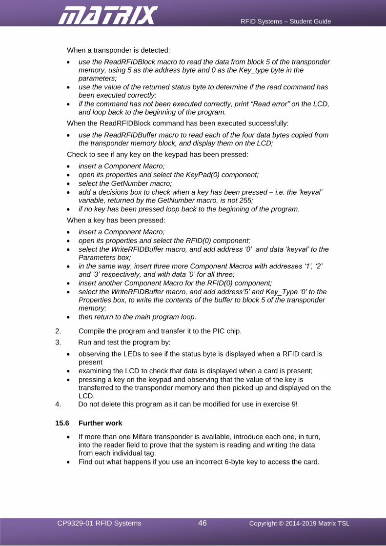
RFID Systems – Student Guide
CP9329-01 RFID Systems 46 Copyright © 2014-2019 Matrix TSL
When a transponder is detected:
• use the ReadRFIDBlock macro to read the data from block 5 of the transponder memory, using 5 as the address byte and 0 as the Key_type byte in the parameters;
• use the value of the returned status byte to determine if the read command has been executed correctly;
• if the command has not been executed correctly, print “Read error” on the LCD, and loop back to the beginning of the program.
When the ReadRFIDBlock command has been executed successfully:
• use the ReadRFIDBuffer macro to read each of the four data bytes copied from the transponder memory block, and display them on the LCD;
Check to see if any key on the keypad has been pressed:
• insert a Component Macro;
• open its properties and select the KeyPad(0) component;
• select the GetNumber macro;
• add a decisions box to check when a key has been pressed – i.e. the ‘keyval’ variable, returned by the GetNumber macro, is not 255;
• if no key has been pressed loop back to the beginning of the program.
When a key has been pressed:
• insert a Component Macro;
• open its properties and select the RFID(0) component;
• select the WriteRFIDBuffer macro, and add address ‘0’ and data ‘keyval’ to the Parameters box;
• in the same way, insert three more Component Macros with addresses ‘1’, ‘2’ and ‘3’ respectively, and with data ‘0’ for all three;
• insert another Component Macro for the RFID(0) component;
• select the WriteRFIDBuffer macro, and add address’5’ and Key_Type ‘0’ to the Properties box, to write the contents of the buffer to block 5 of the transponder memory;
• then return to the main program loop.
2. Compile the program and transfer it to the PIC chip.
3. Run and test the program by:
• observing the LEDs to see if the status byte is displayed when a RFID card is present
• examining the LCD to check that data is displayed when a card is present;
• pressing a key on the keypad and observing that the value of the key is transferred to the transponder memory and then picked up and displayed on the LCD.
4. Do not delete this program as it can be modified for use in exercise 9!
15.6 Further work
• If more than one Mifare transponder is available, introduce each one, in turn, into the reader field to prove that the system is reading and writing the data from each individual tag.
• Find out what happens if you use an incorrect 6-byte key to access the card.
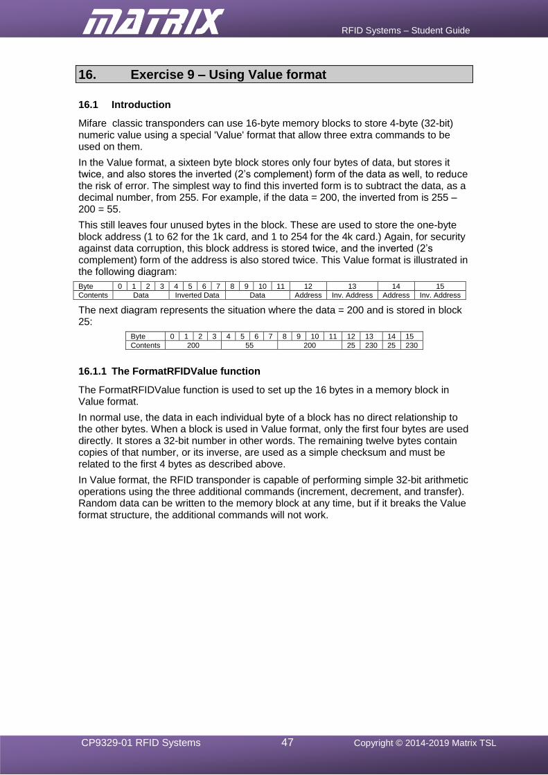
RFID Systems – Student Guide
CP9329-01 RFID Systems 47 Copyright © 2014-2019 Matrix TSL
16. Exercise 9 – Using Value format
16.1 Introduction
Mifare classic transponders can use 16-byte memory blocks to store 4-byte (32-bit) numeric value using a special 'Value' format that allow three extra commands to be used on them.
In the Value format, a sixteen byte block stores only four bytes of data, but stores it twice, and also stores the inverted (2’s complement) form of the data as well, to reduce the risk of error. The simplest way to find this inverted form is to subtract the data, as a decimal number, from 255. For example, if the data = 200, the inverted from is 255 – 200 = 55.
This still leaves four unused bytes in the block. These are used to store the one-byte block address (1 to 62 for the 1k card, and 1 to 254 for the 4k card.) Again, for security against data corruption, this block address is stored twice, and the inverted (2’s complement) form of the address is also stored twice. This Value format is illustrated in the following diagram:
Byte 0 1 2 3 4 5 6 7 8 9 10 11 12 13 14 15
Contents Data Inverted Data Data Address Inv. Address Address Inv. Address
The next diagram represents the situation where the data = 200 and is stored in block 25:
Byte 0 1 2 3 4 5 6 7 8 9 10 11 12 13 14 15
Contents 200 55 200 25 230 25 230
16.1.1 The FormatRFIDValue function
The FormatRFIDValue function is used to set up the 16 bytes in a memory block in Value format.
In normal use, the data in each individual byte of a block has no direct relationship to the other bytes. When a block is used in Value format, only the first four bytes are used directly. It stores a 32-bit number in other words. The remaining twelve bytes contain copies of that number, or its inverse, are used as a simple checksum and must be related to the first 4 bytes as described above.
In Value format, the RFID transponder is capable of performing simple 32-bit arithmetic operations using the three additional commands (increment, decrement, and transfer). Random data can be written to the memory block at any time, but if it breaks the Value format structure, the additional commands will not work.
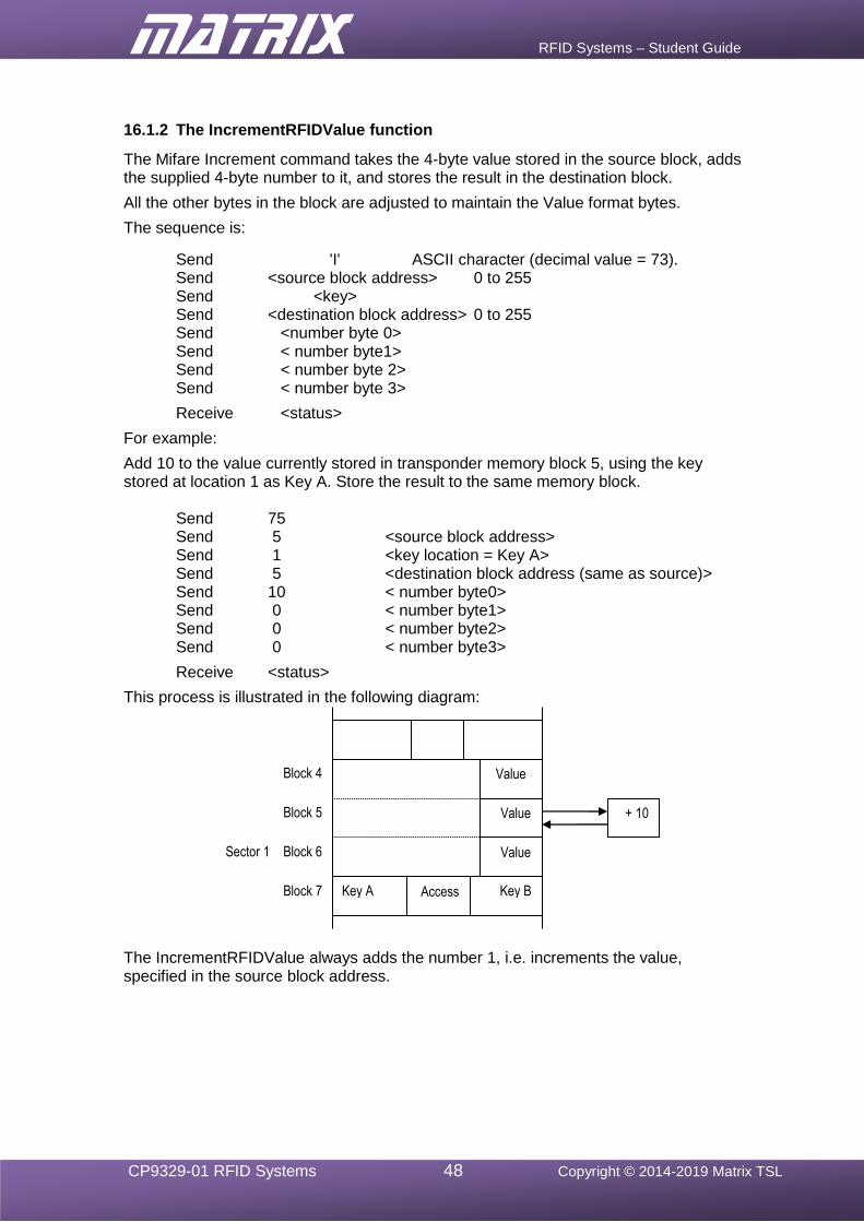
RFID Systems – Student Guide
CP9329-01 RFID Systems 48 Copyright © 2014-2019 Matrix TSL
16.1.2 The IncrementRFIDValue function
The Mifare Increment command takes the 4-byte value stored in the source block, adds the supplied 4-byte number to it, and stores the result in the destination block.
All the other bytes in the block are adjusted to maintain the Value format bytes.
The sequence is:
Send 'I' ASCII character (decimal value = 73). Send <source block address> 0 to 255 Send <key> Send <destination block address> 0 to 255 Send <number byte 0> Send < number byte1> Send < number byte 2> Send < number byte 3>
Receive <status>
For example:
Add 10 to the value currently stored in transponder memory block 5, using the key stored at location 1 as Key A. Store the result to the same memory block.
Send 75 Send 5 <source block address> Send 1 <key location = Key A> Send 5 <destination block address (same as source)> Send 10 < number byte0> Send 0 < number byte1> Send 0 < number byte2> Send 0 < number byte3>
Receive <status>
This process is illustrated in the following diagram:
The IncrementRFIDValue always adds the number 1, i.e. increments the value, specified in the source block address.
Block 7
Block 6
Block 5
Block 4
Sector 1
+ 10
Value
Value
Value
Key A Key B Access
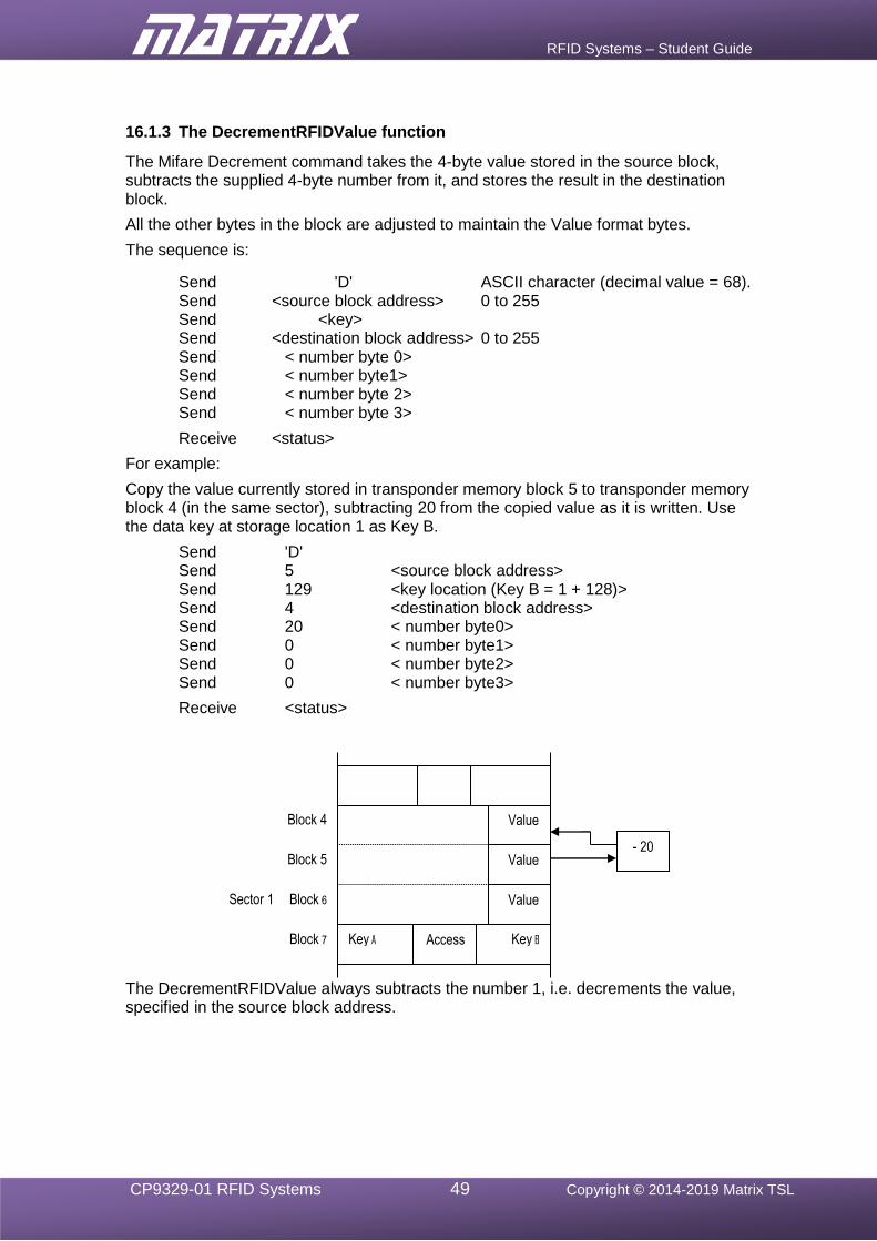
RFID Systems – Student Guide
CP9329-01 RFID Systems 49 Copyright © 2014-2019 Matrix TSL
16.1.3 The DecrementRFIDValue function
The Mifare Decrement command takes the 4-byte value stored in the source block, subtracts the supplied 4-byte number from it, and stores the result in the destination block.
All the other bytes in the block are adjusted to maintain the Value format bytes.
The sequence is:
Send 'D' ASCII character (decimal value = 68). Send <source block address> 0 to 255 Send <key> Send <destination block address> 0 to 255 Send < number byte 0> Send < number byte1> Send < number byte 2> Send < number byte 3>
Receive <status>
For example:
Copy the value currently stored in transponder memory block 5 to transponder memory block 4 (in the same sector), subtracting 20 from the copied value as it is written. Use the data key at storage location 1 as Key B.
Send 'D' Send 5 <source block address> Send 129 <key location (Key B = 1 + 128)> Send 4 <destination block address> Send 20 < number byte0> Send 0 < number byte1> Send 0 < number byte2> Send 0 < number byte3>
Receive <status>
The DecrementRFIDValue always subtracts the number 1, i.e. decrements the value, specified in the source block address.
Block 7
Block 6
Block 5
Block 4
Sector 1
- 20
Value
Value
Value
Key A Key B Access
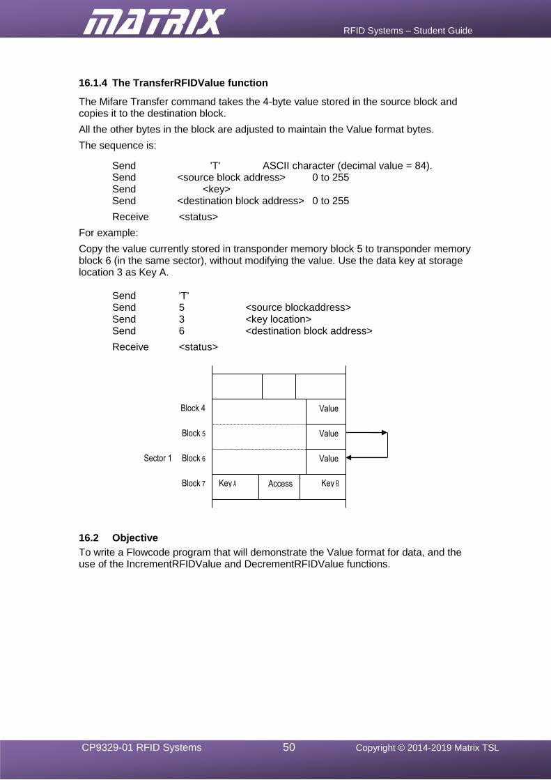
RFID Systems – Student Guide
CP9329-01 RFID Systems 50 Copyright © 2014-2019 Matrix TSL
16.1.4 The TransferRFIDValue function
The Mifare Transfer command takes the 4-byte value stored in the source block and copies it to the destination block.
All the other bytes in the block are adjusted to maintain the Value format bytes.
The sequence is:
Send 'T' ASCII character (decimal value = 84). Send <source block address> 0 to 255 Send <key> Send <destination block address> 0 to 255
Receive <status>
For example:
Copy the value currently stored in transponder memory block 5 to transponder memory block 6 (in the same sector), without modifying the value. Use the data key at storage location 3 as Key A.
Send 'T' Send 5 <source blockaddress> Send 3 <key location> Send 6 <destination block address>
Receive <status>
16.2 Objective
To write a Flowcode program that will demonstrate the Value format for data, and the use of the IncrementRFIDValue and DecrementRFIDValue functions.
Block 7
Block 6
Block 5
Block 4
Sector 1
Value
Value
Value
Key A Key B Access
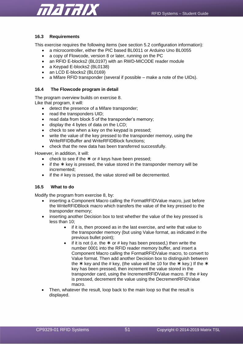
RFID Systems – Student Guide
CP9329-01 RFID Systems 51 Copyright © 2014-2019 Matrix TSL
16.3 Requirements
This exercise requires the following items (see section 5.2 configuration information):
• a microcontroller, either the PIC based BL0011 or Arduino Uno BL0055
• a copy of Flowcode, version 8 or later, running on the PC
• an RFID E-blocks2 (BL0197) with an RWD-MICODE reader module
• a Keypad E-blocks2 (BL0138)
• an LCD E-blocks2 (BL0169) • a Mifare RFID transponder (several if possible – make a note of the UIDs).
16.4 The Flowcode program in detail
The program overview builds on exercise 8. Like that program, it will:
• detect the presence of a Mifare transponder;
• read the transponders UID;
• read data from block 5 of the transponder’s memory;
• display the 4 bytes of data on the LCD;
• check to see when a key on the keypad is pressed;
• write the value of the key pressed to the transponder memory, using the WriteRFIDBuffer and WriteRFIDBlock functions;
• check that the new data has been transferred successfully.
However, in addition, it will:
• check to see if the or # keys have been pressed;
• if the key is pressed, the value stored in the transponder memory will be incremented;
• if the # key is pressed, the value stored will be decremented.
16.5 What to do
Modify the program from exercise 8, by:
• inserting a Component Macro calling the FormatRFIDValue macro, just before the WriteRFIDBlock macro which transfers the value of the key pressed to the transponder memory;
• inserting another Decision box to test whether the value of the key pressed is less than 10;
• if it is, then proceed as in the last exercise, and write that value to the transponder memory (but using Value format, as indicated in the previous bullet point);
• if it is not (i.e. the or # key has been pressed,) then write the number 0001 into the RFID reader memory buffer, and insert a Component Macro calling the FormatRFIDValue macro, to convert to Value format. Then add another Decision box to distinguish between the key and the # key, (the value will be 10 for the key.) If the key has been pressed, then increment the value stored in the transponder card, using the IncrementRFIDValue macro. If the # key is pressed, decrement the value using the DecrementRFIDValue macro.
• Then, whatever the result, loop back to the main loop so that the result is displayed.
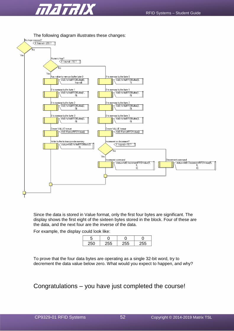
RFID Systems – Student Guide
CP9329-01 RFID Systems 52 Copyright © 2014-2019 Matrix TSL
The following diagram illustrates these changes:
Since the data is stored in Value format, only the first four bytes are significant. The display shows the first eight of the sixteen bytes stored in the block. Four of these are the data, and the next four are the inverse of the data.
For example, the display could look like:
5 0 0 0
250 255 255 255
To prove that the four data bytes are operating as a single 32-bit word, try to decrement the data value below zero. What would you expect to happen, and why?
Congratulations – you have just completed the course!


![[0] Elektor Rfid Reader d060928](https://img.pdfslide.net/doc/110x75/55cf9d33550346d033aca2e2/0-elektor-rfid-reader-d060928.jpg)