Embed Size (px)
Citation preview

509 01 3605 00 2/3/15Specifications subject to change without notice.
INSTALLATION INSTRUCTIONSR−410A Single Package Gas Heating /
Electric CoolingRGS090 − 150
These instructions must be read and understood completely before attempting installation.
DANGER, WARNING, CAUTION, andNOTEThe signal words DANGER, WARNING,CAUTION, and NOTE are used to identify levels ofhazard seriousness. The signal word DANGER isonly used on product labels to signify an immediatehazard. The signal words WARNING, CAUTION,and NOTE will be used on product labels andthroughout this manual and other manuals that mayapply to the product.
DANGER − Immediate hazards which will result insevere personal injury or death.
WARNING − Hazards or unsafe practices whichcould result in severe personal injury or death.
CAUTION − Hazards or unsafe practices whichmay result in minor personal injury or product orproperty damage.
NOTE − Used to highlight suggestions which willresult in enhanced installation, reliability, oroperation.
Signal Words in Manuals
The signal word WARNING is used throughout thismanual in the following manner:
The signal word CAUTION is used throughout thismanual in the following manner:
Signal Words on Product Labeling
Signal words are used in combination with colorsand/or pictures on product labels.
WARNING
Safety Labeling and Signal Words
!
CAUTION
WARNING
!
! WARNING
ELECTRICAL SHOCK HAZARD
Failure to follow this warning could result in personalinjury and/or death.
Before installing, modifying, or servicing system, mainelectrical disconnect switch must be in the OFF posi-tion. There may be more than 1 disconnect switch.Lock out and tag switch with a suitable warning label.
PERSONAL INJURY AND ENVIRONMENTALHAZARD
Failure to follow this warning could cause personalinjury or death.
Relieve pressure and recover all refrigerant beforesystem repair or final unit disposal.
Wear safety glasses and gloves when handlingrefrigerants. Keep torches and other ignitionssources away from refrigerants and oils.
! WARNING
! CAUTIONCUT HAZARD
Failure to follow this caution may result in personal in-jury
Sheet metal parts may have sharp edges or burrs. Usecare and wear appropriate protective clothing andgloves when handling parts.
UNIT OPERATION AND SAFETY HAZARD
Failure to follow this warning could cause personalinjury, death and/or equipment damage.
R−410A refrigerant systems operate at higherpressures than standard R−22 systems. Do notuse R−22 service equipment or components onR−410A refrigerant equipment.
! WARNING

2 509 01 3605 00Specifications subject to change without notice.
IMPORTANT − READ BEFORE INSTALLING1. Read and become familiar with these installation
instructions before installing this unit.2. Be sure the installation conforms to all applicable local and
national codes.3. These instructions contain important information for the
proper maintenance and repair of this equipment. Retainthese instructions for future use.
CONTENTS
SAFETY CONSIDERATIONS 3. . . . . . . . . . . . . . . . . . . . . . . . .
INSTALLATION 4. . . . . . . . . . . . . . . . . . . . . . . . . . . . . . . . . . . . .
Step 1 − Plan for Unit Location 6. . . . . . . . . . . . . . . . . . . . . .
Step 2 − Plan for Sequence of Unit Installation 7. . . . . . . . .
Step 3 − Inspect unit 8. . . . . . . . . . . . . . . . . . . . . . . . . . . . . . .
Step 4 − Provide Unit Support 8. . . . . . . . . . . . . . . . . . . . . . .
Step 5 − Field Fabricate Ductwork 10. . . . . . . . . . . . . . . . . .
Step 6 − Rig and Place Unit 10. . . . . . . . . . . . . . . . . . . . . . . .
Step 7 − Convert to Horizontal and Connect Ductwork 11. .
Step 8 − Install Outside Air Hood 11. . . . . . . . . . . . . . . . . . . . .
Step 9 − Install Flue Hood 13. . . . . . . . . . . . . . . . . . . . . . . . . .
Step 10 − Install Gas Piping 13. . . . . . . . . . . . . . . . . . . . . . . .
Step 11 − Install External Condensate Trap &Piping 15. . .
Step 12 − Make Electrical Connections 16. . . . . . . . . . . . . .
Step 13 − Adjust Factory−Installed Options 26. . . . . . . . . . .
Step 14 − Install Accessories 26. . . . . . . . . . . . . . . . . . . . . . .
UNIT START−UP CHECKLIST 27. . . . . . . . . . . . . . . . . . . . .
SAFETY CONSIDERATIONSImproper installation, adjustment, alteration, service,maintenance, or use can cause explosion, fire, electricalshock or other conditions which may cause personal injury orproperty damage. Consult a qualified installer, serviceagency, or your distributor or branch for information orassistance. The qualified installer or agency must usefactory−authorized kits or accessories when modifying thisproduct. Refer to the individual instructions packaged withthe kits or accessories when installing.
Follow all safety codes. Wear safety glasses and workgloves. Use quenching cloths for brazing operations andhave a fire extinguisher available. Read these instructionsthoroughly and follow all warnings or cautions attached tothe unit. Consult local building codes and appropriatenational electrical codes (in USA, ANSI/NFPA70, NationalElectrical Code (NEC); in Canada, CSA C22.1) for specialrequirements.
Recognize safety information. This is the safety−alert symbol . When you see this symbol in instructions or manuals,be alert to the potential for personal injury.
Understand the signal words DANGER, WARNING,CAUTION, and NOTE. These words are used with thesafety−alert symbol. DANGER identifies the most serioushazards which will result in serious injury or death. WARNINGsignifies a hazard which could result in serious injury or death.CAUTION is used to identify unsafe practices which may resultin minor personal injury or product and property damage.NOTE is used to highlight suggestions which will result inenhanced installation, reliability, or operation.
These instructions cover minimum requirements and conformto existing national standards and safety codes. In someinstances, these instructions exceed certain local codes andordinances, especially those that may not have kept up withchanging residential construction practices. We require theseinstructions as a minimum for a safe installation.
FIRE, EXPLOSION HAZARD
Failure to follow this warning could result in personalinjury or death.
Disconnect gas piping from unit when leak testing atpressure greater than 0.5 psig (3450 Pa). Pressuresgreater than 0.5 psig (3450 Pa) will cause gas valvedamage resulting in hazardous condition. If gas valve issubjected to pressure greater than 0.5 psig (3450 Pa), itmust be replaced before use. When pressure testingfield−supplied gas piping at pressures of 0.5 psig (3450Pa) or less, a unit connected to such piping must beisolated by closing the manual gas valve.
! WARNING
ELECTRICAL SHOCK HAZARD
Failure to follow this warning could cause personal injuryor death.
Before performing service or maintenance operations onunit, always turn off main power switch to unit and installlockout tag. Unit may have more than one power switch.
! WARNING
INSTALLATION
UNIT OPERATION AND SAFETY HAZARD
Failure to follow this warning could cause personal injury,death and/or equipment damage.
R−410A refrigerant systems operate at higher pressuresthan standard R−22 systems. Do not use R−22 serviceequipment or components on R−410A refrigerantequipment.
! WARNING
!

3509 01 3605 00 Specifications subject to change without notice.
MODEL NOMENCLATUREMODEL SERIES R G S 0 9 0 H D A A 0 A G A
Position Number 1 2 3 4 5 6 7 8 9 10 11 12 13 14R = Rooftop
A = Air Conditioning (Cooling Only)G = Gas/Electric Type
S = Standard ASHRAE 90.1-2010 Efficiency Efficiency
091 = 90,000 = 7.5 Tons (One Compressor)101 = 102,000 = 8.5 Tons (One Compressor)121 = 120,000 = 10 Tons (One Compressor)090 = 90,000 = 7.5 Tons (Two Compressors)102 = 102,000 = 8.5 Tons (Two Compressors)120 = 120,000 = 10 Tons (Two Compressors)150 = 150,000 = 12.5 Tons (Two Compressors) Nominal Cooling Capacity
H = 208/230-3-60L = 460-3-60S = 575-3-60 Voltage
D = Low HeatE = Medium HeatF = High Heat Heating CapacityA = Standard MotorB = High Static Motor Motor OptionA = NoneB = Economizer w/Bara-relief, OA Temp Sensor
Outdoor Air Options / Control (see Specification Sheet for details)
0A = No OptionsFactory Installed Options (see Specification Sheet for details)
A = Aluminum / Copper Cond & Evap Coil (RTPF - Round tube/Plate Fin coil)Standard Condenser / Evaporator Coil Configuration
A = Sales Digit

4 509 01 3605 00Specifications subject to change without notice.
Figure 1 Base Unit Dimensions: RGS090−121
5509 01 3605 00 Specifications subject to change without notice.
Figure 1A Base Unit Dimensions: RGS150
6 509 01 3605 00Specifications subject to change without notice.
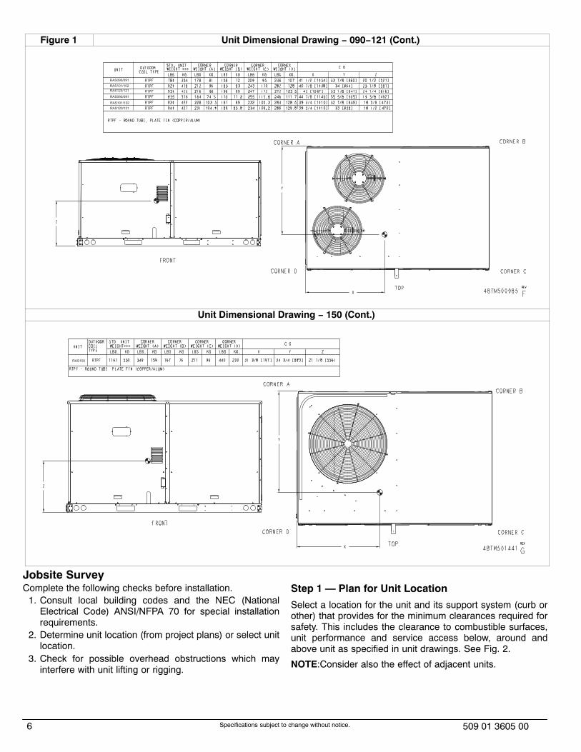
Figure 1 Unit Dimensional Drawing − 090−121 (Cont.)
Unit Dimensional Drawing − 150 (Cont.)
50
Jobsite SurveyComplete the following checks before installation.
1. Consult local building codes and the NEC (NationalElectrical Code) ANSI/NFPA 70 for special installationrequirements.
2. Determine unit location (from project plans) or select unitlocation.
3. Check for possible overhead obstructions which mayinterfere with unit lifting or rigging.
Step 1 — Plan for Unit Location
Select a location for the unit and its support system (curb orother) that provides for the minimum clearances required forsafety. This includes the clearance to combustible surfaces,unit performance and service access below, around andabove unit as specified in unit drawings. See Fig. 2.
NOTE:Consider also the effect of adjacent units.

7509 01 3605 00 Specifications subject to change without notice.
C
BA
D
Figure 2 Service Clearance Dimensional Drawing
C08337
LOCATION DIMENSION CONDITION
A
48-in (1219 mm)
18-in (457 mm)
18-in (457) mm
12-in (305 mm)
Unit disconnect is mounted on panel
No disconnect, convenience outlet option
Recommended service clearance
Minimum clearance
B
42-in (1067 mm)
36-in (914 mm)
Special
Surface behind servicer is grounded (e.g., metal, masonry wall)
Surface behind servicer is electrically non-conductive (e.g., wood, fiberglass)
Check sources of flue products within 10-ft of unit fresh air intake hood
C36-in (914 mm)
18-in (457 mm)
Side condensate drain is used
Minimum clearance
D
48-in (1219 mm)
42-in (1067 mm)
36-in (914 mm)
Special
No flue discharge accessory installed, surface is combustible material
Surface behind servicer is grounded (e.g., metal, masonry wall, another unit)
Surface behind servicer is electrically non-conductive (e.g., wood, fiberglass)
Check for adjacent units or building fresh air intakes within 10-ft (3 m) of this unit's flue outlet
NOTE: Unit not designed to have overhead obstruction. Contact Application Engineering for guidance on any application planning overhead obstruction or for vertical clearances.
Be sure that unit is installed such that snow will not block thecombustion intake or flue outlet.
Unit may be installed directly on wood flooring or on Class A,B, or C roof−covering material when roof curb is used.
Do not install unit in an indoor location. Do not locate airinlets near exhaust vents or other sources of contaminatedair. For proper unit operation, adequate combustion andventilation air must be provided in accordance with Section5.3 (Air for Combustion and Ventilation) of the National FuelGas Code, ANSI Z223.1 (American National StandardsInstitute) and NFPA (National Fire Protection Association) 54TIA−54−84−1. In Canada, installation must be in accordancewith the CAN1−B149 installation codes for gas burningappliances.
Although unit is weatherproof, avoid locations that permitwater from higher level runoff and overhangs to fall onto theunit.Locate mechanical draft system flue assembly at least 4 ft(1.2 m) from any opening through which combustion
products could enter the building, and at least 4 ft (1.2 m)from any adjacent building (or per local code). Locate theflue assembly at least 10 ft (3.05 m) from an adjacent unit’sfresh air intake hood if within 3 ft (0.91 m) of same elevation(or per local code). When unit is located adjacent to publicwalkways, flue assembly must be at least 7 ft (2.1 m) abovegrade.Select a unit mounting system that provides adequate heightto allow installation of condensate trap per requirements.Refer to Step 11 — Install External Trap for CondensateDrain – for required trap dimensions.Roof mount —Check building codes for weight distribution requirements.Unit operating weight is shown in Table 1.
Step 2 — Plan for Sequence of Unit InstallationThe support method used for this unit will dictate differentsequences for the steps of unit installation. For example, oncurb−mounted units, some accessories must be installed on

8 509 01 3605 00Specifications subject to change without notice.
the unit before the unit is placed on the curb. Review thefollowing for recommended sequences for installation steps.Curb−mounted installation —
Install roof curbInstall field−fabricated ductwork inside curbInstall accessory thru−base service connection package, ifused, (affects curb and unit) (refer to accessory installationinstructions for details)Prepare condensate drain connection to suit plannedcondensate line routing (refer to Step 11 for details)Rig and place unitInstall outdoor air hoodInstall flue hoodInstall gas pipingInstall condensate line trap and pipingMake electrical connectionsInstall other accessories
Pad−mounted installation —Prepare pad and unit supportsCheck and tighten the bottom condensate drain connectionplugRig and place unitConvert unit to side duct connection arrangementInstall field−fabricated ductwork at unit duct openingsInstall outdoor air hoodInstall flue hoodInstall gas pipingInstall condensate line trap and pipingMake electrical connectionsInstall other accessories
Frame−mounted installation —Frame−mounted applications generally follow thesequence for a curb installation. Adapt as required to suitspecific installation plan.
Step 3 — Inspect unitInspect unit for transportation damage. File any claim withtransportation agency.Confirm before installation of unit that voltage, amperageand circuit protection requirements listed on unit data plateagree with power supply provided.
Step 4 — Provide Unit SupportRoof Curb Mount —Accessory roof curb details and dimensions are shown inFig. 3. Assemble and install accessory roof curb inaccordance with instructions shipped with the curb.NOTE:The gasketing of the unit to the roof curb is critical fora watertight seal. Install gasket supplied with the roof curb asshown in Fig. 3. Improperly applied gasket can also result inair leaks and poor unit performance.Curb should be level. This is necessary for unit drain tofunction properly. Unit leveling tolerances are show in Fig. 4.Refer to Accessory Roof Curb Installation Instructions foradditional information as required.Install insulation, cant strips, roofing felt, and counter flashingas shown. Ductwork must be attached to curb and not to theunit. The accessory thru−the−base power and gasconnection package must be installed before the unit is seton the roof curb. If field−installed thru−the−roof curb gasconnections are desired, use factory−supplied 1/2−in. pipecoupling and gas plate assembly to mount the thru−the−roofcurb connection to the roof curb. Gas connections and powerconnections to the unit must be field installed after the unit isinstalled on the roof curb.If electric and control wiring is to be routed through thebasepan, attach the accessory thru−the−base serviceconnections to the basepan in accordance with theaccessory installation instructions.Slab Mount (Horizontal Units Only) —Provide a level concrete slab that extends a minimum of 6 in.(150 mm) beyond unit cabinet. Install a gravel apron in frontof condenser coil air inlet to prevent grass and foliage fromobstructing airflow.NOTE:Horizontal units may be installed on a roof curb ifrequired.
Alternate Unit Support (In Lieu of Curb or Slab Mount) —A non−combustible sleeper rail can be used in the unit curbsupport area. If sleeper rails cannot be used, support thelong sides of the unit with a minimum of three equally spaced4−in. x 4−in. (102 mm x 102 mm) pads on each side.
Table 1—Operating Weights
UNIT / COIL TYPEUNITS LB (KG)
090/091 101/102 120/121 150
RGS 780 (354) 920 (418) 930 (422) N/A
RGS 835 (379) 930 (422) 940 (427) 1167 (530)
RGS 805 (366) N/A 895(406) 1116 (506)
OPTIONS &ACCESSORES
Economizer
�Vertical 75 (34) 75 (34) 75 (34) 75 (34)
�Horizontal 122 (55) 122 (55) 122 (55) 122 (55)
Powered Outlet 35 (16) 35 (16) 35 (16) 35 (16)
Curb
�14-in/356 mm 143 (65) 143 (65) 143 (65) 143 (65)
�24-in/610 mm 245 (111) 245 (111) 245 (111) 245 (111)

9509 01 3605 00 Specifications subject to change without notice.
Figure 3 Roof Curb Details
7/16
"[1
1]
4 9/
16"
[115
.5]
1/4"
[7.0
]
"A"
1 3/
4"[4
4.5]
1 3/
4"[4
4.4]
20-3
/4"
[513
]IN
SID
E
"A"
81 3
/4"
[207
6.3]
53 1
/2"
[135
8.9]
1 3/
4"[4
4.5]
40 3
/16"
[102
0.8]
2 1/
4"[5
7.2]
26"
[660
.4]
4 3/
16"
[106
.0]
6 3/
64"
[153
.5]
32 9
/16"
[827
.1]
23 1
/16"
[585
.8]
31 1
7/32
"[8
00.9
]1
3/4"
[44.
5]
15 1
3/16
"[4
01.6
]
11.4
2"[2
90.0
]
1 3/
4"[4
4.4]
3"[7
6.2]
2-3/
8"[6
1]
14 3
/4"
[374
.7]
6' 6
-1/4
"[1
987.
5]
1-3
/4"
TY
P [4
4.5]
4' 2
"[1
270.
0]
15 1
5/32
[392
.9]
1.00
"[2
5.4]
CR
BTM
PW
R00
2A01
3/4"
[19]
NP
T1
1/4"
[31.
7] N
PT
CR
RFC
UR
B00
4A01
CO
NN
EC
TOR
PK
G. A
CC
.G
AS
CO
NN
EC
TIO
N T
YP
EG
AS
FIT
TIN
GP
OW
ER
WIR
ING
FI
TTIN
GC
ON
TRO
L W
IRIN
G
FITT
ING
AC
CE
SS
OR
Y C
ON
VE
NIE
NC
E
OU
TLE
T W
IRIN
G C
ON
NE
CTO
R
THR
U T
HE
CU
RB
1/2"
[12.
7] N
PT
1/2"
[12.
7] N
PT
CR
BTM
PW
R00
4A01
THR
U T
HE
BO
TTO
M
RO
OF
CU
RB
AC
CE
SS
OR
Y #
A
CR
RFC
UR
B00
3A01
14"
[356
]
24"
[610
]
RE
V
50
HJ4
0501
2C
NO
TES
:1.
RO
OFC
UR
B A
CC
ES
SO
RY
IS S
HIP
PE
D D
ISA
SS
EM
BLE
D.
2. IN
SU
LATE
D P
AN
ELS
: 25.
4 [1
"] TH
K. P
OLY
UR
ETH
AN
E F
OA
M, 4
4.5
[1-3
/4] #
DE
NS
ITY
.3.
DIM
EN
SIO
NS
IN [
] A
RE
IN M
ILLI
ME
TER
S.
4. R
OO
FCU
RB
: 18
GA
GE
STE
EL.
5. A
TTA
CH
DU
CTW
OR
K T
O C
UR
B. (
FLA
NG
ES
OF
DU
CT
RE
ST
ON
CU
RB
).6.
SE
RV
ICE
CLE
AR
AN
CE
4 F
EE
T O
N E
AC
H S
IDE
.7.
D
IRE
CTI
ON
OF
AIR
FLO
W.
8. C
ON
NE
CTO
R P
AC
KA
GE
CR
BTM
PW
R00
2A01
IS F
OR
TH
RU
-TH
E-C
UR
B G
AS
TY
PE
P
AC
KA
GE
CR
BTM
PW
R00
4A01
IS F
OR
TH
RU
-TH
E-B
OTT
OM
TY
PE
GA
S C
ON
NE
CTI
ON
S.
TYP
ICA
L (4
) SID
ES
SU
PP
LY A
IRR
ETU
RN
AIR
RO
OFI
NG
MA
TER
IAL
(FIE
LD S
UP
PLI
ED
)
CA
NT
STR
IP(F
IELD
SU
PP
LIE
D)
RO
OFI
NG
FE
LT(F
IELD
SU
PP
LIE
D)
CO
UN
TER
FLA
SH
ING
(FIE
LD S
UP
PLI
ED
)
UN
ITG
AS
KE
T(S
UP
PLI
ED
WIT
H C
UR
B)
RIG
ID IN
SU
LATI
ON
(FIE
LD S
UP
PLI
ED
)
DU
CT
(FIE
LD S
UP
PLI
ED
)
NA
IL (F
IELD
SU
PP
LIE
D)
VIE
W "B
"C
OR
NE
R D
ETA
IL
SE
CTI
ON
TH
RU
SID
E
SE
E V
IEW
"B
"
GA
S S
ER
VIC
E P
LATE
TH
RU
TH
E C
UR
B
DR
ILL
HO
LE
2" [5
0.8]
@
AS
SE
MB
LY (I
F R
EQ
UIR
ED
) (S
EE
NO
TE #
8)
SE
E N
OTE
#2
12-1
/2" [
317.
5] W
IDE
INS
ULA
TED
DE
CK
PA
NE
LS
9-15
/16"
[252
.4] W
IDE
INS
ULA
TED
DE
CK
PA
NE
L
SU
PP
LY A
IRR
ETU
RN
AIR
SU
PP
LY A
IRO
PE
NIN
G
RE
TUR
N A
IRO
PE
NIN
G

10 509 01 3605 00Specifications subject to change without notice.
Figure 4 Unit Leveling Tolerances
MAXIMUM ALLOWABLE
A−B B−C A−C0.5”(13) 1.0” (25) 1.0” (25)
Step 5 — Field Fabricate Ductwork
Cabinet return-air static pressure (a negative condition) shallnot exceed 0.35 in. wg (87 Pa) with economizer or 0.45 in.wg (112 Pa) without economizer.
For vertical ducted applications, secure all ducts to roof curband building structure. Do not connect ductwork to unit.
Insulate and weatherproof all external ductwork, joints, androof openings with counter flashing and mastic inaccordance with applicable codes.
Ducts passing through unconditioned spaces must beinsulated and covered with a vapor barrier.
If a plenum return is used on a vertical unit, the return shouldbe ducted through the roof deck to comply with applicablefire codes.
A minimum clearance is not required around ductwork.
Step 6 — Rig and Place Unit
Keep unit upright and do not drop. Spreader bars are notrequired if top crating is left on unit. Rollers may be used tomove unit across a roof. Level by using unit frame as areference. See Table 1 and Fig. 5 for additional information.
Lifting holes are provided in base rails as shown in Fig. 5.Refer to rigging instructions on unit.
UNIT DAMAGE HAZARD
Failure to follow this caution may result in equipmentdamage.
All panels must be in place when rigging. Unit is notdesigned for handling by fork truck.
CAUTION!
Before setting the unit onto the curb, recheck gasketing oncurb.
Figure 5 Rigging Details
UNITMAX WEIGHT
DIMENSIONS
A B C
LB KG IN MM IN MM IN MM
RGS091 1325 602 88.0 2235 42.0 1065 41.5 1055
RGS101 1440 655 88.0 2235 41.5 1055 49.5 1255
RGS121 1550 705 88.0 2235 42.5 1080 49.5 1255
RGS090 1445 657 88.0 2235 43.0 1090 41.5 1055
RGS102 1565 711 88.0 2235 42.5 1080 49.5 1255
RGS120 1605 730 88.0 2235 42.0 1065 49.5 1255
RGS150 1760 800 88.0 2235 29.5 750 53.0 1345
NOTES:
1. Dimensions in ( ) are in millimeters.
2. SPREADER BARS REQUIRED — Top damage will occur if spreader bars are not used.
3. Hook rigging shackles through holes in base rail, as shown in detail “A.” Holes in base rails are centered around the unit center of gravity. Use wooden top to prevent rigging straps from damaging unit.

11509 01 3605 00 Specifications subject to change without notice.
Positioning on Curb —Position unit on roof curb so that the following clearances aremaintained: 1/4 in. (6.4 mm) clearance between the roof curband the base rail inside the front and rear, 0.0 in. clearancebetween the roof curb and the base rail inside on the ductend of the unit. This will result in the distance between theroof curb and the base rail inside on the condenser end ofthe unit being approximately equal to Fig. 3, section C−C.Although unit is weatherproof, guard against water fromhigher level runoff and overhangs.
UNIT DAMAGE HAZARD
Failure to follow this caution may result inequipment damage.
All panels must be in place when rigging. Unit isnot designed for handling by fork truck.
CAUTION!
Flue vent discharge must have a minimum horizontalclearance of 4 ft (1220 mm) from electric and gas meters,gas regulators, and gas relief equipment. Minimum distancebetween unit and other electrically live parts is 48 inches(1220 mm).Flue gas can deteriorate building materials. Orient unit suchthat flue gas will not affect building materials. Locatemechanical draft system flue assembly at least 48 in. (1220mm) from an adjacent building or combustible material.NOTE:Installation of accessory flue discharge deflector kitwill reduce the minimum clearance to combustible material to18 in. (460 mm).After unit is in position, remove rigging skids and shippingmaterials.Step 7 — Convert to Horizontal and ConnectDuctwork (when required)Unit is shipped in the vertical duct configuration. Unit withoutfactory−installed economizer may be field−converted tohorizontal ducted configuration. To convert to horizontalconfiguration, remove screws from side duct opening coversand remove covers. Using the same screws, install coverson vertical duct openings with the insulation−side down.Seals around duct openings must be tight. See Fig. 6.
Figure 6 HORIZONTAL CONVERSION PANELS
C06108
Field−supplied flanges should be attached to horizontal ductopenings and all ductwork should be secured to the flanges.Insulate and weatherproof all external ductwork, joints, androof or building openings with counter flashing and mastic inaccordance with applicable codes.
Do not cover or obscure visibility to the unit’s informativedata plate when insulating horizontal ductwork.
Step 8 — Install Optional Outside Air HoodEconomizer Hood Removal and Setup − Factory Option
1. The hood is shipped in knock−down form and located inthe return air compartment. It is attached to theeconomizer using two plastic tie−wraps.
2. To gain access to the hood, remove the filter accesspanel. (See Fig. 7.)
3. Locate and cut the (2) plastic tie−wraps, being careful tonot damage any wiring. (See Fig. 8.)
4. Carefully lift the hood assembly through the filter accessopening and assemble per the steps outlined inEconomizer Hood and Two–Position Hood.
Figure 7 Typical Access Panel Locations
Filter Access Panel
Outdoor Air Opening and Indoor Coil Access Panel
Figure 8 Economizer Wiring
Economizer
Cut Plastic Ties(2) Places
Remove Hood Parts
C08633
Two Position Damper Hood Removal and Setup —Factory Option
1. The hood is shipped in knock−down form and assembledto a metal support tray using plastic stretch wrap.Located in the return air compartment, the assembly’s

12 509 01 3605 00Specifications subject to change without notice.
metal tray is attached to the basepan and also attachedto the damper using two plastic tie−wraps.
2. To gain access to the hood, remove the filter accesspanel. See Fig. 7.
3. Locate the (2) screws holding the metal tray to thebasepan and remove. Locate and cut the (2) plastictie−wraps securing the assembly to the damper. (SeeFig. 9.) Be careful to not damage any wiring or cuttie−wraps securing any wiring.
4. Carefully lift the hood assembly (with metal tray) throughthe filter access opening and assemble per the stepsoutlined in Economizer Hood and Two–Position Hood.
Figure 9 Damper Assembly
Hood Parts
Plastic Tie WrapQty (2)
Screws for Metal TrayQty (2)
Economizer Hood and Two−Position Damper Hood(Optional) —NOTE:If the power exhaust accessory is to be installed onthe unit, the hood shipped with the unit will not be used andmust be discarded. Save the aluminum filter for use in thepower exhaust hood assembly.
1. The indoor coil access panel will be used as the top ofthe hood. Remove the screws along the sides andbottom of the indoor coil access panel. See Fig. 10.
Figure 10 Indoor Coil Access Panel Relocation
SIDEPANEL
INDOORCOILACCESSPANEL
CAULKHERE
TOPSIDEPANEL
C06025
2. Swing out indoor coil access panel and insert the hoodsides under the panel (hood top). Use the screwsprovided to attach the hood sides to the hood top. Usescrews provided to attach the hood sides to the unit. SeeFig. 11.
Figure 11 Economizer Hood Construction
3. Remove the shipping tape holding the economizerbarometric relief damper in place.
4. Insert the hood divider between the hood sides. See Fig.11 and 12. Secure hood divider with 2 screws on eachhood side. The hood divider is also used as the bottomfilter rack for the aluminum filter.
5. Open the filter clips which are located underneath thehood top. Insert the aluminum filter into the bottom filterrack (hood divider). Push the filter into position past theopen filter clips. Close the filter clips to lock the filter intoplace. See Fig. 12.
Figure 12 Economizer Filter Installation
6. Caulk the ends of the joint between the unit top paneland the hood top.
7. Replace the filter access panel.

13509 01 3605 00 Specifications subject to change without notice.
Step 9 — Install Flue Hood
Flue hood is shipped screwed to the basepan beside theburner compartment access panel. Remove from shippinglocation and using screws provided, install flue hood andscreen in location shown in Fig. 13.
Figure 13 Flue Hood Details
Flue Opening
BlowerAccessPanel
C07081
Step 10 — Install Gas Piping
Installation of the gas piping must be accordance with localbuilding codes and with applicable national codes. In U.S.A.,refer to NFPA 54/ANSI Z223.1 National Fuel Gas Code(NFGC). In Canada, installation must be accordance with theCAN/CSA B149.1 and CAN/CSA B149.2 installation codesfor gas burning appliances.
Note: Furnace gas input rate on rating plate is for installationup to 2000 ft (610m) above sea level. In U.S.A. the inputrating for altitudes above 2000 ft (610m) must be derated by4% for each 1000 ft (305m) above sea level. In Canada theinput rating must ve derated by 10% for altitudes of 2000 ft(610m) to 4500 ft (1372m) above sea level.
For natural gas applications, gas pressure at unit gas connectionmust not be less than 4 in. wg (996 Pa) or greater than 13 in. wg(3240 Pa) while the unit is operating. For liquified petroleumapplications, the gas pressure must not be less than 11 in. wg (2740Pa) or greater than 13.6 in. wg (3390 Pa) at the unit connection.
Table 2—Natural Gas Supply Line Pressure Ranges
UNIT MODEL UNIT SIZE MIN MAX
RGS 090-1504.0 in. wg(996 Pa)
13.0 in. wg(3240 Pa)
Table 3—Liquid Propane Supply Line Pressure Ranges
UNIT MODEL UNIT SIZE MIN MAX
RGS 090-15011.0 in. wg(2740 Pa)
13.0 in. wg(3240 Pa)
The gas supply pipe enters the unit at the burner accesspanel on the front side of the unit, through the long slot at thebottom of the access panel. The gas connection to the unit is
made to the 1/2−in. or 3/4−in. FPT gas inlet port on the unitgas valve.
Manifold pressure is factory−adjusted for NG fuel use. Adjustas required to obtain best flame characteristics.
Table 4—Natural Gas Manifold Pressure Ranges
UNIT MODEL UNIT SIZE HIGH FIRE LOW FIRE�
RGS 090-1503.5 in. wg(872 Pa)
2.0 in. wg(498 Pa)
�NOTE- LOW FIRE, 1.7 in. Wg (423 Pa), applies to the following units only: RGS090*D/S & RGS102*D/S
Manifold pressure for LP fuel use must be adjusted tospecified range. Follow instructions in the accessory kit tomake initial readjustment.
Table 5—Liquid Propane Manifold Pressure Ranges
UNIT MODEL UNIT SIZE HIGH FIRE LOW FIRE�
RGS 090-15010.0 in. wg(2490 Pa)
5.7 in. wg(1420 Pa)
�NOTE- LOW FIRE, 5.0 in. Wg (1420 Pa), applies to the following units only: RGS090*D/S & RGS102*D/S
EQUIPMENT DAMAGE HAZARD
Failure to follow this caution may result in damage toequipment.
When connecting the gas line to the unit gas valve, theinstaller MUST use a backup wrench to prevent damageto the valve.
CAUTION!
Install a gas supply line that runs to the unit heating section.Refer to the NFPA 54/NFGC or equivalent code for gas pipesizing data. Do not use a pipe smaller than the sizespecified. Size the gas supply line to allow for a maximumpressure drop of 0.5−in wg (124 Pa) between gas regulatorsource and unit gas valve connection when unit is operatingat high−fire flow rate.The gas supply line can approach the unit in three ways:horizontally from outside the unit (across the roof),thru−curb/under unit basepan (accessory kit required) orthrough unit basepan (factory−option or accessory kitrequired). Consult accessory kit installation instructions fordetails on these installation methods.Optional Thru−Base Connections —This accessory (field installed) service connection kitconsists of a NPT gas adapter fitting, a 1−1/4−in electricalbulkhead connector and a 1/2−in electrical bulkheadconnector, all installed in the embossed (raised) section ofthe unit basepan in the condenser section.Note: This must be installed prior to mounting unit onroof curb.

14 509 01 3605 00Specifications subject to change without notice.
Figure 14 Thru−Base Connection Fittings
LOW VOLTAGECONDUITCONNECTOR
HIGH VOLTAGECONDUITCONNECTOR
BRASS FITTING FOR 3 TO 6 TON UNITS.
C13410
The thru−base gas connector has male and female threads.The male threads protrude above the basepan of the unit;the female threads protrude below the basepan.
Check tightness of connector lock nuts before connectinggas piping.
Gas Line: Install a 1/2−in (for 7.5 & 8.5 Ton low gas unitsonly) or 3/4−in (for all other units) NPT street elbow on thethru−base gas fitting. Attach an appropriate size pipe nipplewith minimum length of 19−in (483 mm) (field−supplied) tothe street elbow and extend it through the access panel atthe gas support bracket. See Fig. 15.
Figure 15 Gas Line Piping
EMBOSSMENT BRASS FITTINGFOR 3-6 TON UNITS
SUPPORTBRACKET
C13411
Other hardware required to complete the installation of thegas supply line will include a manual shutoff valve, asediment trap (drip leg) and a ground−joint union. A pressureregulator valve may also be required (to convert gaspressure from pounds to inches of pressure). The manualshutoff valve must be located within 6−ft (1.83 m) of the unit.The union, located in the final leg entering the unit, must belocated at least 9−in (230 mm) away from the access panelto permit the panel to be removed for service. If a regulatorvalve is installed, it must be located a minimum of 4−ft (1220mm) away from the unit’s flue outlet. Some municipal codesrequire that the manual shutoff valve be located upstream ofthe sediment trap. See Figures 16 and 17 for typical pipingarrangements for gas piping that has been routed throughthe sidewall of the curb. See Fig. 18 for typical pipingarrangement when thru−base is used. Ensure that all piping
does not block access to the unit’s main control box or limitthe required working space in front of the control box.
Figure 16 Gas Piping with Thru−Curb Accessory
9” (229mm) min
Union
Shut OffValve
DripLeg
Thru−Curb Adapter
Unit Base Rail
C07469
Figure 17Gas Piping with Thru−Curb Accessory(alternate layout)
DripLeg
Shut OffValve
Union
Thru−Curb Adapter
BurnerAccessPanel
9” (229mm) min
Unit Base Rail
C07470
Figure 18 Gas Piping with Thru−Base Accessory
C08018

15509 01 3605 00 Specifications subject to change without notice.
When installing the gas supply line, observe local codespertaining to gas pipe installations. Refer to the NFPA54/ANSI Z223.1 NFGC latest edition (in Canada, CAN/CSAB149.1). In the absence of local building codes, adhere tothe following pertinent recommendations:
1. Avoid low spots in long runs of pipe. Grade all pipe1/4−in. in every 15 ft (7 mm in every 5 m) to preventtraps. Grade all horizontal runs downward to risers. Userisers to connect to heating section and to meter.
2. Protect all segments of piping system against physicaland thermal damage. Support all piping with appropriatestraps, hangers, etc. Use a minimum of one hangerevery 6 ft (1.8 m). For pipe sizes larger than 1/2−in.,follow recommendations of national codes.
3. Apply joint compound (pipe dope) sparingly and only tomale threads of joint when making pipe connections.Use only pipe dope that is resistant to action of liquefiedpetroleum gases as specified by local and/or nationalcodes. If using PTFE (Teflon) tape, ensure the material isDouble Density type and is labeled for use on gas lines.Apply tape per manufacturer’s instructions.
4. Pressure−test all gas piping in accordance with local andnational plumbing and gas codes before connectingpiping to unit.
NOTE:Pressure test the gas supply system after the gassupply piping is connected to the gas valve. The supplypiping must be disconnected from the gas valve during thetesting of the piping systems when test pressure is in excessof 0.5 psig (3450 Pa). Pressure test the gas supply pipingsystem at pressures equal to or less than 0.5 psig (3450 Pa).The unit heating section must be isolated from the gas pipingsystem by closing the external main manual shutoff valveand slightly opening the ground−joint union.
Check for gas leaks at the field−installed andfactory−installed gas lines after all piping connections havebeen completed. Use soap−and−water solution (or methodspecified by local codes and/or regulations).
FIRE OR EXPLOSION HAZARD
Failure to follow this warning could result in personalinjury, death and/or property damage.
� Connect gas pipe to unit using a backup wrench to avoid damaging gas controls.
� Never purge a gas line into a combustion chamber. � Never test for gas leaks with an open flame. Use a
commercially available soap solution made specifically for the detection of leaks to check all connections.
� Use proper length of pipe to avoid stress on gas control manifold.
! WARNING
NOTE:If orifice hole appears damaged or it is suspected tohave been redrilled, check orifice hole with a numbered drillbit of correct size. Never redrill an orifice. A burr−free and
squarely aligned orifice hole is essential for proper flamecharacteristics.
Figure 19 Orifice Hole
BURNERORIFICE
A93059
Step 11 — Install External Condensate Trap andLine
The unit has one 3/4-in. condensate drain connection on theend of the condensate pan and an alternate connection onthe bottom. See Fig. 20. Unit airflow configuration does notdetermine which drain connection to use. Either drainconnection can be used with vertical or horizontalapplications.
When using the standard side drain connection, ensure thered plug in the alternate bottom connection is tight. Do thisbefore setting the unit in place. The red drain pan can betightened with a 1/2−in. square socket drive extension.
To use the alternate bottom drain connection, remove the reddrain plug from the bottom connection (use a 1/2−in. squaresocket drive extension) and install it in the side drainconnection.
Figure 20 Condensate Drain Pan (Side View)
DRAIN(FACTORY-INSTALLED)
PLUG
CONDENSATE PAN (SIDE VIEW)
STANDARDSIDE DRAIN
ALTERNATEBOTTOM DRAIN
The piping for the condensate drain and external trap can becompleted after the unit is in place. See Fig. 21.
All units must have an external trap for condensate drainage.Install a trap at least 4-in. (102 mm) deep and protect againstfreeze-up. If drain line is installed downstream from theexternal trap, pitch the line away from the unit at 1-in. per 10ft (25 mm in 3 m) of run. Do not use a pipe size smaller thanthe unit connection (3/4-in.).

16 509 01 3605 00Specifications subject to change without notice.
Figure 21 Condensate Drain Piping Details
NOTE: Trap should be deep enough to offset maximum unit staticdifference. A 4” (102) trap is recommended.
MINIMUM PITCH1” (25mm) PER10’ (3m) OF LINE
BASE RAIL
OPENVENT
TO ROOFDRAIN
DRAIN PLUG
ROOFCURB
SEE NOTE
2˝ (51) MIN
Step 12 — Make Electrical Connections
ELECTRICAL SHOCK HAZARD
Failure to follow this warning could result in personalinjury or death.
Do not use gas piping as an electrical ground. Unitcabinet must have an uninterrupted, unbroken electricalground to minimize the possibility of personal injury if anelectrical fault should occur. This ground may consist ofelectrical wire connected to unit ground lug in controlcompartment, or conduit approved for electrical groundwhen installed in accordance with NEC (NationalElectrical Code); ANSI/NFPA 70, latest edition (inCanada, Canadian Electrical Code CSA [CanadianStandards Association] C22.1), and local electrical codes.
! WARNING
NOTE:Check all factory and field electrical connectionsfor tightness. Field−supplied wiring shall conform withthe limitations of 63�F (33�C) rise.
Field Power Supply —
All units except 208/230-v units are factory wired for thevoltage shown on the nameplate. If the 208/230-v unit is tobe connected to a 208-v power supply, the controltransformer must be rewired by moving the black wire withthe 1/4-in. female spade connector from the 230−vconnection and moving it to the 200-v 1/4-in. male terminalon the primary side of the transformer. Refer to unit labeldiagram for additional information. Field power wires will beconnected line−side pressure lugs on the power terminalblock or at factory−installed option non−fused disconnect.
Field power wires are connected to the unit at line−sidepressure lugs on compressor contactor C and indoor fancontactor IFC (see wiring diagram label for control boxcomponent arrangement) or at factory−installed optionnon−fused disconnect switch. Max wire size is #2 AWG(copper only).
NOTE:TEST LEADS − Unit may be equipped with shortleads (pigtails) on the field line connection points oncontactor C or optional disconnect switch. These leads are
for factory run−test purposes only; remove and discardbefore connecting field power wires to unit connection points.Make field power connections directly to line connectionpressure lugs only.
FIRE HAZARD
Failure to follow this warning could result in intermittentoperation or performance satisfaction.
Do not connect aluminum wire between disconnectswitch and furnace. Use only copper wire.
! WARNING
Figure 22 Disconnect Switch and Unit
SWITCH
ALUMINUMWIRE
A93033
Units Without Factory−Installed Disconnect —
When installing units, provide a disconnect switch per NEC(National Electrical Code) of adequate size. Disconnectsizing data is provided on the unit informative plate. Locateon unit cabinet or within sight of the unit per national or localcodes. Do not cover unit informative plate if mounting thedisconnect on the unit cabinet.
Units with Factory−Installed Disconnect —
The factory−installed option disconnect switch is located in aweatherproof enclosure located under the main control box.The manual switch handle is accessible through an openingin the access panel.
All units −
All field wiring must comply with NEC and all local codes.Size wire based on MCA (Minimum Circuit Amps) on the unitinformative plate. See Fig. 21 for power wiring connectionsto the unit power terminal block and equipment ground.Maximum wire size is #2 ga AWG per pole.
Provide a ground−fault and short−circuit over−currentprotection device (fuse or breaker) per NEC Article 440 (orlocal codes). Refer to unit informative data plate for MOCP(Maximum Over−current Protection) device size.

17509 01 3605 00 Specifications subject to change without notice.
Figure 23 Power Wiring Connections
C IFC
Disconnect factory test leadsand discard.
13 13
L1 L2 L3208/230-3-60
460-3-60575-3-60
Units Without Disconnect Option
Units With Disconnect Option
1 3 5
2 4 6
L1 L2 L3
FactoryWiring
Disconnectper
NEC
OptionalDisconnect
Switch
11
All field wiring must comply with the NEC and localrequirements.Convenience Outlets —
ELECTRICAL OPERATION HAZARD
Failure to follow this warning could result inpersonal injury or death.
Units with convenience outlet circuits may usemultiple disconnects. Check convenience outletfor power status before opening unit for service.Locate its disconnect switch, if appropriate, andopen it. Tag−out this switch, if necessary.
! WARNING
An optional non−powered convenience outlet is offered onRGS models that provide a 125−volt GFCI (ground−faultcircuit−interrupter) duplex receptacle rated at 15−A behind ahinged access cover, located on the corner panel of the unit.See Fig. 24.
Figure 24 Convenience Outlet Location
ConvenienceOutlet
ElectricDisconnect
Switch
Control BoxAccess Panel
Installing Weatherproof Cover –
A weatherproof while-in-use cover for the factory-installedconvenience outlets is now required by UL standards. Thiscover cannot be factory-mounted due its depth; it must beinstalled at unit installation. For shipment, the convenienceoutlet is covered with a blank cover plate.
The weatherproof cover kit is shipped in the unit’s controlbox. The kit includes the hinged cover, a backing plate andgasket.
DISCONNECT ALL POWER TO UNIT AND CONVENIENCEOUTLET.
Remove the blank cover plate at the convenience outlet;discard the blank cover.
Loosen the two screws at the GFCI duplex outlet, untilapproximately 1/2-in (13 mm) under screw heads areexposed. Press the gasket over the screw heads. Slip thebacking plate over the screw heads at the keyhole slots andalign with the gasket; tighten the two screws until snug (donot over-tighten).
Mount the weatherproof cover to the backing plate as shownin Fig. 25. Remove two slot fillers in the bottom of the coverto permit service tool cords to exit the cover. Check for fullclosing and latching.
Figure 25 Weatherproof Cover Installation
RECEPTACLENOT INCLUDED
COVER – WHILE-IN-USE WEATHERPROOF
BASE PLATE FOR GFCI RECEPTACLE

18 509 01 3605 00Specifications subject to change without notice.
Non−powered type: This type requires the field installationof a general−purpose 125−volt 15−A circuit powered from asource elsewhere in the building. Observe national and localcodes when selecting wire size, fuse or breakerrequirements and disconnect switch size and location. Route125−v power supply conductors into the bottom of the utilitybox containing the duplex receptacle.
Optional Thru−Base Connections —
This accessory (field installed) service connection kitconsists of an appropriate size NPT gas adapter fitting, a1−1/4−in and a 1/2−in electrical bulkhead connector, all mustbe installed in the embossed (raised) section of the unitbasepan in the condenser section. The 1/2−in bulkheadconnector enables the low−voltage control wires to passthrough the basepan. The 1−1/4−in electrical bulkheadconnector allows the high−voltage power wires to passthrough the basepan. See Fig. 14. Note: This must be installed prior to mounting unit onroof curb.
Check tightness of connector lock nuts before connectingelectrical conduits.
Field−supplied and field−installed liquid tight conduitconnectors and conduit may be attached to the connectorson the basepan. Pull correctly rated high voltage and lowvoltage through appropriate conduits. Connect the powerconduit to the internal disconnect (if unit is so equipped) or tothe external disconnect (through unit side panel). A holemust be field cut in the main control box bottom on the leftside so the 24−v control connections can be made. Connectthe control power conduit to the unit control box at this hole.
Units without Thru−Base Connections —
1. Install power wiring conduit through side panel openings.Install conduit between disconnect and control box.
2. Install power lines to terminal connections as shown inFig. 23.
Voltage to compressor terminals during operation must bewithin voltage range indicated on unit nameplate. See Table2. On 3−phase units, voltages between phases must bebalanced within 2% and the current within 10%. Use theformula shown in the legend for Table 2, Note 2 to determinethe percent of voltage imbalance. Operation on improper linevoltage or excessive phase imbalance constitutes abuse andmay cause damage to electrical components. Suchoperation would invalidate any applicable warranty.
Field Control Wiring —
The RGS unit requires an external temperature controldevice. This device typically applied with a commercialthermostat (field−supplied) with both occupied andunoccupied setpoints at a minimum.
Thermostat —
Install an approved accessory commercial two−stagethermostat according to installation instructions included withthe accessory. Locate the thermostat accessory on a solidwall in the conditioned space to sense average temperaturein accordance with the thermostat installation instructions.
If the thermostat contains a logic circuit requiring 24−vpower, use a thermostat cable or equivalent single leads ofdifferent colors with minimum of seven leads. If thethermostat does not require a 24−v source (no “C”connection required), use a thermostat cable or equivalentwith minimum of six leads. Check the thermostat installationinstructions for additional features which might requireadditional conductors in the cable.
For wire runs up to 50 ft. (15 m), use no. 18 AWG (AmericanWire Gage) insulated wire (35�C minimum). For 50 to 75 ft.(15 to 23 m), use no. 16 AWG insulated wire (35�Cminimum). For over 75 ft. (23 m), use no. 14 AWG insulatedwire (35�C minimum). All wire sizes larger than no. 18 AWGcannot be directly connected to the thermostat and willrequire a junction box and splice at the thermostat.
Figure 26 Typical Low Voltage Control Connections
TypicalThermostatConnections
CentralTerminal Board
W1
Y2
Y1
R
W2
G
C
X
W1
Y2
Y1
R
W2
G
C
X
T–STAT
C
W2
G
W1
O/B/Y2
R
Y1
(see Note)
Note : Typical multi-function marking. Follow manufacturer’s configuration instructions to select Y2. Field Wiring
Unit without thru−base connection kit —
Pass the thermostat control wires through the hole providedin the corner post; then feed the wires through the raceway

19509 01 3605 00 Specifications subject to change without notice.
built into the corner post to the control box. Pull the wiresover to the terminal strip on the upper−left corner of theControls Connection Board. See Fig. 27.
Figure 27 Field Control Wiring Raceway
RACEWAY
HOLE IN END PANEL (HIDDEN)
NOTE:If thru−the−bottom connections accessory is used,refer to the accessory installation instructions for informationon routing power and control wiring.
Heat Anticipator Settings —
Set heat anticipator settings at 0.14 amp for the first stageand 0.14 amp for second−stage heating, when available.
SMOKE DETECTORS
Smoke detectors are available as factory−installed optionson RGS models. Smoke detectors may be specified forSupply Air only without or with economizer. All componentsnecessary for operation are factory−provided and mounted.The unit is factory−configured for immediate smoke detectorshutdown operation; additional wiring or modifications to unitterminal board may be necessary to complete the unit andsmoke detector configuration to meet project requirements.
SystemThe smoke detector system consists of a four−wire controllerand one or two sensors. Its primary function is to shut downthe rooftop unit in order to prevent smoke from circulatingthroughout the building. It is not to be used as a life savingdevice.
ControllerThe controller (see Fig. 28) includes a controller housing, aprinted circuit board, and a clear plastic cover. The controllercan be connected to one or two compatible duct smokesensors. The clear plastic cover is secured to the housingwith a single captive screw for easy access to the wiringterminals. The controller has three LEDs (for Power, Troubleand Alarm) and a manual test/reset button (on the coverface).
SensorThe sensor (see Fig. 29) includes a plastic housing, a printedcircuit board, a clear plastic cover, a sampling tube inlet and
an exhaust tube. The sampling tube (when used) andexhaust tube are attached during installation. The samplingtube varies in length depending on the size of the rooftopunit. The clear plastic cover permits visual inspectionswithout having to disassemble the sensor. The coverattaches to the sensor housing using four captive screwsand forms an airtight chamber around the sensingelectronics. Each sensor includes a harness with an RJ45terminal for connecting to the controller. Each sensor hasfour LEDs (for Power, Trouble, Alarm and Dirty) and amanual test/reset button (on the left−side of the housing).
Air is introduced to the duct smoke detector sensor’s sensingchamber through a sampling tube that extends into theHVAC duct and is directed back into the ventilation systemthrough a (shorter) exhaust tube. The difference in airpressure between the two tubes pulls the sampled airthrough the sensing chamber. When a sufficient amount ofsmoke is detected in the sensing chamber, the sensorsignals an alarm state and the controller automatically takesthe appropriate action to shut down fans and blowers,change over air handling systems, notify the fire alarmcontrol panel, etc.
The sensor uses a process called differential sensing toprevent gradual environmental changes from triggering falsealarms. A rapid change in environmental conditions, such assmoke from a fire, causes the sensor to signal an alarm statebut dust and debris accumulated over time does not.
For installations using two sensors, the duct smoke detectordoes not differentiate which sensor signals an alarm ortrouble condition.
Figure 28 Controller Assembly
Duct smoke sensorcontroller
Fastener(2X)
Controller cover
Conduit nuts(supplied by installer)
Conduit support plate
Cover gasket(ordering option)
Conduit couplings(supplied by installer)
Terminal block cover
Controller housingand electronics
Alarm Power
Test/resetswitch
Trouble

20 509 01 3605 00Specifications subject to change without notice.
Figure 29 Smoke Detector Sensor
Duct smoke sensor
Exhaust tube
Intakegasket
Cover gasket(ordering option)
TSD-CO2(ordering option)
Sensor housingand electronics
Sensor cover
Magnetictest/reset
switch
AlarmTrouble
PowerDirty
Smoke Detector Locations
Supply Air — The Supply Air smoke detector sensor islocated to the left of the unit’s indoor (supply) fan. See Fig.30. Access is through the fan access panel. There is nosampling tube used at this location. The sampling tube inletextends through the side plate of the fan housing (into a highpressure area). The controller is located on a bracket to theright of the return filter, accessed through the lift−off filterpanel.
Figure 30Typical Supply Air Smoke Detector SensorLocations
ROTATIO
N
Return Air Sampling Tube(Shipping Location)
Hot Gas ReHeat Connections
Hot Gas ReHeat – Space RH Controller —
The Hot Gas ReHeat dehumidification system requires afield−supplied and −installed space relative humidity controldevice. This device may be a separate humidistat control(contact closes on rise in space RH above control setpoint)or a combination thermostat−humidistat control device withisolated contact set for dehumidification control. Thehumidistat is normally used in applications where atemperature control is already provided.To connect the humidistat:
1. Route the humidistat 2−conductor cable (field−supplied)through the hole provided in the unit corner post. (SeeFigure 27)
2. Feed wires through the raceway built into the corner postto the 24−v barrier located on the left side of the controlbox. The raceway provides the UL−required clearancebetween high−voltage and low−voltage wiring.
3. Use wire nuts to connect humidistat cable to two PINKleads in the low–voltage wiring as shown in Figure 33.
To connect the Thermidistat device:1. Route the Thermidistat multi−conductor thermostat cable
(field−supplied) through the hole provided in the unitcorner post.
2. Feed wires through the raceway built into the corner post(See Figure 27) to the 24−v barrier located on the leftside of the control box. The raceway provides the UL−re-quired clearance between high−voltage and low−voltagewiring.
3. The Thermidistat has dry contacts at terminals D1 andD2 for dehumidification operation (see Figure 34). Thedry contacts must be wired between CTB terminal R andthe PINK lead to the LTLO switch with field−suppliedwire nuts. Refer to the installation instructions includedwith the thermidistat device.
% RELATIVE HUMIDITY
Figure 31 − Accessory Field−Installed Humidistat

21509 01 3605 00 Specifications subject to change without notice.
Figure 32 − Thermidistat
EconoMi$er X (Factory−Installed Option) —
For details on operating RGS units equipped with thefactory−installed EconoMi$er X option, refer toFactory−Installed Economizers for RGH/RAH/RHH/RGS/RAS/RHS Rooftop Units, 3 to 27.5 Nominal Tons. EconomizerSupplement Related to California Title 24 (Literature No.50901350201, or later).
C150021
Figure 33 −Typical Hot Gas ReHeat Adaptive Dehumidification System Humidistat Wiring

22 509 01 3605 00Specifications subject to change without notice.
RcRhW1
GY2C
O/W2/BY1
OATRRS
SRTNHUM
D1D2V+Vg
X*
C
G
W2
W1
Y2
Y1
R
THERMIDISTAT
THERMOSTAT
*Connection not required.
H FIOP
C09298
Figure 34 −Typical Rooftop Unit with Hot Gas ReHeat Adaptive Dehumidification System

23509 01 3605 00 Specifications subject to change without notice.
Table 6—Unit Wire/Fuse or HACR Breaker Sizing Data − Single Speed Indoor Fan Motor
UNIT NOM.V-Ph-HzIFM
TYPE
NO C.O. or UNPWR C.O.
NO P.E. w/ P.E. (pwrd fr/ unit)
MCAFUSE or HACR
BRKR
DISC. SIZEMCA
FUSE or HACRBRKR
DISC. SIZE
FLA LRA FLA LRA
RGS091(1-stage
cool)
208/230-3-60
STD 40/40 60/60 38/38 208 44/43 60/60 43/42 212
MED 43/43 60/60 42/42 244 47/47 60/60 46/46 248
HIGH 48/47 60/60 48/47 260 52/51 60/60 52/51 264
460-3-60
STD 20 30 19 122 22 30 21 124
MED 22 30 21 140 23 30 23 142
HIGH 24 30 23 148 26 30 25 150
575-3-60
STD 15 20 14 89 18 25 18 93
MED 16 20 15 104 20 25 19 108
HIGH 19 25 18 118 22 30 23 122
RGS090(2-stage
cool)
208/230-3-60
STD 39/39 50/50 41/40 210 43/43 50/50 45/45 214
MED 42/42 50/50 44/44 246 46/46 50/50 49/49 250
HIGH 48/47 60/50 50/49 262 51/51 60/60 55/54 266
460-3-60
STD 18 20 19 104 20 25 21 106
MED 20 25 21 122 22 25 23 124
HIGH 22 25 23 130 24 30 25 132
575-3-60
STD 13 15 13 77 17 20 17 81
MED 14 15 14 92 18 20 19 96
HIGH 17 20 17 106 21 25 22 110
See “Legend and Notes for Tables 6 and 7 on page 25.
UNIT NOM.V-Ph-HzIFM
TYPE
NO C.O. or UNPWR C.O.
NO P.E. w/ P.E. (pwrd fr/ unit)
MCAFUSE or
HACR BRKR
DISC. SIZEMCA
FUSE or HACRBRKR
DISC. SIZE
FLA LRA FLA LRA
RGS101(1-stage
cool)
208/230-3-60
STD 46/45 60/60 43/43 239 49/49 60/60 48/47 243
MED 47/47 60/60 45/45 260 51/51 60/60 50/49 264
HIGH 51 60 50 289 55 80 54 293
460-3-60
STD 23 30 22 117 25 30 24 119
MED 24 30 23 127 26 30 25 129
HIGH 26 30 25 142 28 40 27 144
575-3-60
STD 19 30 17 91 22 30 22 95
MED 19 30 18 95 23 30 22 99
HIGH 20 30 19 106 24 30 23 110
RGS102(2-stage
cool)
208/230-3-60
STD 40/40 50/50 42/42 225 44/44 50/50 46/46 229
MED 42/42 50/50 44/44 246 46/46 60/50 48/48 250
HIGH 46 50 48 275 50 60 52 279
460-3-60
STD 19 20 19 118 20 25 21 120
MED 20 25 20 128 21 25 22 130
HIGH 21 25 22 143 23 25 24 145
575-3-60
STD 16 20 16 85 19 25 20 89
MED 16 20 16 89 20 25 20 93
HIGH 17 20 17 100 21 25 21 104
RGS121(1-stage
cool)
208/230-3-60
STD 48/48 60/60 46/46 290 52/52 60/60 50/50 294
MED 52 60 50 319 55 80 55 323
HIGH 55/54 80/80 54/53 321 58/58 80/80 58/57 325
460-3-60
STD 26 40 25 146 28 40 27 148
MED 28 40 27 161 30 45 29 163
HIGH 29 45 28 162 31 45 30 164
575-3-60
STD 19 30 18 95 23 30 22 99
MED 20 30 19 106 24 30 23 110
HIGH 23 30 22 120 26 30 26 124
RGS120(2-stage
cool)
208/230-3-60
STD 46/46 60/60 48/47 285 50/49 60/60 52/52 289
MED 50 60 52 314 53 60 56 318
HIGH 53/52 60/60 55/54 316 56/55 60/60 60/59 320
460-3-60
STD 23 30 23 136 25 30 26 138
MED 25 30 26 151 26 30 28 153
HIGH 26 30 27 152 28 30 29 154
575-3-60
STD 17 20 17 93 20 25 21 97
MED 17 20 18 104 21 25 22 108
HIGH 20 25 21 118 24 30 25 122
See “Legend and Notes for Tables 6 and 7 on page 25.

24 509 01 3605 00Specifications subject to change without notice.
Table 6 – Unit Wire/Fuse or HACR Breaker Sizing Data − Single Speed Indoor Fan Motor (cont)
UNIT NOM.V-Ph-HzIFM
TYPE
NO C.O. or UNPWR C.O.
NO P.E. w/ P.E. (pwrd fr/ unit)
MCAFUSE or HACR
BRKR
DISC. SIZEMCA
FUSE or HACRBRKR
DISC. SIZE
FLA LRA FLA LRA
RGS150(2-stage
cool)
Units built onor after
02/16/2015
208/230-3-60
STD 63/63 80/80 65/65 389 66/66 80/80 69/69 393
MED 65 80 68 403 69 80 72 407
HIGH 68/67 80/80 71/70 405 72/71 80/80 75/74 409
460-3-60
STD 29 35 30 193 31 40 32 195
MED 30 40 31 200 32 40 33 202
HIGH 31 40 33 201 33 40 35 203
575-3-60
STD 22 25 23 147 26 30 27 151
MED 22 25 23 147 26 30 27 151
HIGH 25 30 26 161 29 35 30 165
RGS150(2-stage
cool)
Units built onor prior to02/15/2015
208/230-3-60
STD 62/62 80/80 64/64 376 66/66 80/80 69/69 380
MED 64 80 67 390 68 80 71 394
HIGH 67/66 80/80 70/69 392 71/70 80/80 75/74 396
460-3-60
STD 31 40 32 189 33 40 34 191
MED 32 40 33 196 34 40 35 198
HIGH 33 40 34 197 35 40 36 199
575-3-60
STD 23 30 23 142 27 30 28 146
MED 23 30 23 142 27 30 28 146
HIGH 26 30 27 156 29 35 31 160
See “Legend and Notes for Tables 6 and 7 on page 25.
Table 7—Unit Wire/Fuse or HACR Breaker Sizing Data − 2−Speed Indoor Fan Motor
UNIT NOM.V-Ph-HzIFM
TYPE
NO C.O. or UNPWR C.O.
NO P.E. w/ P.E. (pwrd fr/ unit)
MCAFUSE or HACR
BRKR
DISC. SIZEMCA
FUSE or HACRBRKR
DISC. SIZE
FLA LRA FLA LRA
RGS090(2-stage
cool)
208/230-3-60
STD 40/40 50/50 41/41 197 44/43 50/50 46/46 201
MED 43/42 50/50 45/44 227 46/46 50/50 49/48 231
HIGH 48/47 60/50 50/49 262 51/51 60/60 55/54 266
460-3-60
STD 19 20 19 97 20 25 21 99
MED 20 25 20 113 21 25 22 115
HIGH 22 25 23 130 24 30 25 132
575-3-60
STD 14 15 14 79 18 20 19 83
MED 16 20 16 92 19 25 21 96
HIGH 18 20 18 106 22 25 23 110
RGS102(2-stage
cool)
208/230-3-60
STD 41/41 50/50 43/42 212 45/45 50/50 47/47 216
MED 42/42 50/50 44/44 216 46/46 60/50 48/48 220
HIGH 46/45 60/50 48/47 266 50/49 60/60 53/52 270
460-3-60
STD 19 25 20 111 21 25 22 113
MED 20 25 21 114 22 25 23 116
HIGH 21 25 22 139 23 25 24 141
575-3-60
STD 17 20 17 87 21 25 21 91
MED 17 20 18 91 21 25 22 95
HIGH 18 20 19 100 22 25 23 104
RGS120(2-stage
cool)
208/230-3-60
STD 46/46 60/60 48/47 255 50/50 60/60 52/52 259
MED 50/49 60/60 52/51 305 54/53 60/60 56/55 309
HIGH 53/52 60/60 55/54 316 56/55 60/60 60/59 320
460-3-60
STD 23 30 24 122 25 30 26 124
MED 24 30 25 147 26 30 27 149
HIGH 26 30 27 152 28 30 29 154
575-3-60
STD 18 20 19 95 22 25 23 99
MED 19 25 20 104 23 25 24 108
HIGH 21 25 22 118 25 30 26 122
See “Legend and Notes for Tables 6 and 7 on page 25.

25509 01 3605 00 Specifications subject to change without notice.
Table 7 − Unit Wire/Fuse or HACR Breaker Sizing Data − 2−Speed Indoor Fan Motor
UNIT NOM.V-Ph-HzIFM
TYPE
NO C.O. or UNPWR C.O.
NO P.E. w/ P.E. (pwrd fr/ unit)
MCAFUSE or HACR
BRKR
DISC. SIZEMCA
FUSE or HACRBRKR
DISC. SIZE
FLA LRA FLA LRA
RGS150(2-stage
cool)
Units builton or after02/16/2015
208/230-3-60
STD 63/62 80/80 65/64 370 67/66 80/80 70/69 374
MED 65/64 80/80 68/67 394 69/68 80/80 72/71 398
HIGH 68/67 80/80 71/70 405 72/71 80/80 75/74 409
460-3-60
STD 29 35 30 184 31 40 32 186
MED 30 40 31 196 32 40 33 198
HIGH 31 40 33 201 33 40 35 203
575-3-60
STD 24 30 24 147 27 30 29 151
MED 24 30 24 147 27 30 29 151
HIGH 25 30 26 161 29 35 31 165
RGS150(2-stage
cool)
Units built onor prior to02/15/2015
208/230-3-60
STD 62/61 80/80 65/64 357 66/65 80/80 69/68 361
MED 64/63 80/80 67/66 381 68/67 80/80 72/70 385
HIGH 67/66 80/80 70/69 392 71/70 80/80 75/74 396
460-3-60
STD 30 40 31 180 32 40 33 182
MED 31 40 33 192 33 40 35 194
HIGH 33 40 34 197 35 40 36 199
575-3-60
STD 24 30 25 142 28 30 30 146
MED 24 30 25 142 28 30 30 146
HIGH 26 30 27 156 30 35 32 160
See “Legend and Notes for Tables 6 and 7 on page 25.
LEGEND:CO - Convenient outletDISC - DisconnectFLA - Full load ampsIFM - Indoor fan motorLRA - Locked rotor ampsMCA - Minimum circuit ampsMOCP - Maximum over current protectionPE - Power exhaustUNPWRD CO - Unpowered convenient outletNOTES:
1. In compliance with NEC requirements for multimotor andcombination load equipment (refer to NEC Articles 430 and440), the overcurrent protective device for the unit shall befuse or HACR breaker. Canadian units may be fuse or circuit breaker.
2. Unbalanced 3‐Phase Supply VoltageNever operate a motor where a phase imbalance in supplyvoltage is greater than 2%. Use the following formula to determine the percentage of voltage imbalance.
% Voltage Imbalance = 100 xmax voltage deviation from average voltage
average voltage
Example: Supply voltage is 230‐3‐60
AB = 224 v
BC = 231 v
AC = 226 v
Average Voltage =(224 + 231 + 226)
=681
3 3
= 227
Determine maximum deviation from average voltage.(AB) 227 – 224 = 3 v(BC) 231 – 227 = 4 v(AC) 227 – 226 = 1 vMaximum deviation is 4 v.Determine percent of voltage imbalance.
% Voltage Imbalance = 100 x4
227
= 1.76%
This amount of phase imbalance is satisfactory as it is below the maximumallowable 2%.IMPORTANT: If the supply voltage phase imbalance is more than 2%,contact your local electric utility company immediately.

26 509 01 3605 00Specifications subject to change without notice.
Figure 35 Wiring for Optional Economizer
Economizer 2 Position Damper Unit Without Economizer or2 Position Damper
Step 13 — Adjust Factory−Installed Options
Smoke Detector —
Smoke detector will be connected at the ControlsConnections Board, at terminals marked “Smoke Shutdown”.Remove jumper JMP 3 when ready to energize unit.
Economizer Occupancy Switch —
Refer to Fig. 31 for general Economizer IV wiring. Externaloccupancy control is managed through a connection on theControls Connections Board.
If external occupancy control is desired, connect a time clockor remotely controlled switch (closed for Occupied, open forUnoccupied sequence) at terminals marked OCCUPANCY.Remove or cut jumper JMP 2 to complete the installation.
Step 14 — Install Accessories, As Required
Available accessories include:
Roof CurbThru−base connection kit (must be installed before unit isset on curb)LP conversion kitManual outside air damperTwo−Position motorized outside air damperEconomizer (with control and integrated barometric relief)Winter start kitPower exhaustOutdoor enthalpy sensorDifferential enthalpy sensorCO2 sensorLow ambient controlFlue gas discharge deflectorHood−type hail guardPhase monitor control
Refer to separate installation instructions for information oninstalling these accessories.

27509 01 3605 00 Specifications subject to change without notice.
UNIT START-UP CHECKLIST(Remove and Store in Job File)
MODEL NO.: SERIAL NO.:
I. PRE-START-UP
� VERIFY THAT ALL PACKAGING MATERIALS HAVE BEEN REMOVED FROM UNIT
� VERIFY INSTALLATION OF OUTDOOR AIR HOOD
� VERIFY INSTALLATION OF FLUE EXHAUST AND INLET HOOD
� VERIFY THAT CONDENSATE CONNECTION IS INSTALLED PER INSTRUCTIONS
� VERIFY THAT ALL ELECTRICAL CONNECTIONS AND TERMINALS ARE TIGHT
� VERIFY GAS PRESSURE TO UNIT GAS VALVE IS WITHIN SPECIFIED RANGE
� CHECK GAS PIPING FOR LEAKS
� CHECK THAT INDOOR−AIR FILTERS ARE CLEAN AND IN PLACE
� CHECK THAT OUTDOOR AIR INLET SCREENS ARE IN PLACE
� VERIFY THAT UNIT IS LEVEL
� CHECK FAN WHEELS AND PROPELLER FOR LOCATION IN HOUSING/ORIFICE AND VERIFY SETSCREW IS TIGHT
� VERIFY THAT FAN SHEAVES ARE ALIGNED AND BELTS ARE PROPERLY TENSIONED
� VERIFY THAT SCROLL COMPRESSORS ARE ROTATING IN THE CORRRECT DIRECTION
� VERIFY INSTALLATION OF THERMOSTAT
� VERIFY THAT CRAKCASE HEATERS HAVE BENN ENERGIZED FOR AT LEAST 24 HOURS
II. START-UPELECTRICALSUPPLY VOLTAGE L1−L2 L2−L3 L3−L1
COMPRESSOR AMPS 1 L1 L2 L3
COMPRESSOR AMPS 2 L1 L2 L3
SUPPLY FAN AMPS L1 L2 L3TEMPERATURESOUTDOOR−AIR TEMPERATURE �F DB (DRY BULB)
RETURN−AIR TEMPERATURE �F DB �F WB (WET BULB)
COOLING SUPPLY AIR TEMPERATURE �F
GAS HEAT SUPPLY AIR �FPRESSURES
GAS INLET PRESSURE IN. WG
GAS MANIFOLD PRESSURE STAGE 1 IN. WG
STAGE 2 IN. WG
REFRIGERANT SUCTION CIRCUIT A PSIG
CIRCUIT B PSIG
REFRIGERANT DISCHARGE CIRCUIT A PSIG
CIRCUIT B PSIG
� VERIFY REFRIGERANT CHARGE USING CHARGING CHARTSGENERAL
� ECONOMIZER MINIMUM VENT AND CHANGEOVER SETTINGS TO JOB REQUIREMENTS (IF EQUIPPED)
� VERIFY SMOKE DETECTOR UNIT SHUTDOWN BY UTILIZING MAGNET TEST

28 509 01 3605 00Specifications subject to change without notice.
III. HOT GAS REHEAT START-UPSTEPS
� 1. CHECK CTB FOR JUMPER 5, 6, 7JUMPER 5, 6, 7 MUST BE CUT AND OPEN
� 2. OPEN HUMIDISTAT CONTACTS
� 3. START UNIT IN COOLING (CLOSE Y1)OBSERVE AND RECORD
A. SUCTION PRESSURE PSIG
B. DISCHARGE PRESSURE PSIG
C. ENTERING AIR TEMPERATURE �F
D. LIQUID LINE TEMPERATUREAT OUTLET OR REHEAT COIL �F
E. CONFRIM CORRECT ROTATION FOR COMPRESSOR
F. CHECK FOR CORRECT RAMP−UP OF OJUTDOOR FAN MOTOR AS CONDENSER COIL WARMS
� 4. CHECK UNIT CHARGE PER CHARGING CHART
� 5. SWITCH UNIT TO HIGH−LATENT MODE (SUBCOOLER) BY CLOSING HUMIDISTAT WITH Y1 CLOSED
OBSERVE
� A. REDUCTION IN SUCTION PRESSURE (5 TO 7 PSI EXPECTED)
� B. DISCHARGE PRESSURE UNCHANGED
� C. LIQUID TEMPERATURE DROPS TO 50 TO 55�F RANGE
� D. LSV SOLENOID ENGERIZED (VALVE CLOSES)
� 6. SWITCH UNIT TO DEHUMID (REHEAT) BY OPENING Y1
OBSERVE
� A. SUCTION PRESSURE INCREASES TO NORMAL COOLING LEVEL
� B. DISCHARGE PRESSURE DECREASES (35 TO 50 PSI)
� C. LIQUID TEMPERATURE RETURNS TO NORMAL COOLNG LEVEL
� D. LSV SOLENOID ENERGIZED (VALVE CLOSES)
� E. DSV SOLENOID ENERGIZED, VALVE OPENS
� 7. WITH UNIT IN DEHUMID MODE CLOSE W1COMPRESSOR AND OUTDOOR FAN STOP; LSV AND DSV SOLENOIDS DE−ENERGIZED
� 8. OPEN W1 RESTORE UNIT TO DEHUMID MODE
� 9. OPEN HUMIDISTAT INPUTCOMPRESSOR AND OUTDOOR FAN STOP; LSV AND DSV SOLENOIDS DE−ENERGIZED
� 10. RESTORE SETPOINTS FOR THERMOSTAT AND HUMIDISTAT
Copyright 2015 International Comfort ProductsLewisburg, TN 37091 USA