Embed Size (px)
Citation preview
THIS MODEL
17.010.0
USES LESS ENERGY
Seasonal Energy Efficiency Ratio - SEER
17.00
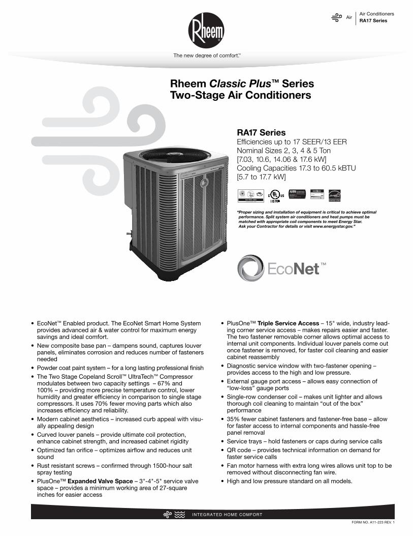
Rheem Classic Plus™ SeriesTwo-Stage Air Conditioners
FORM NO. A11-223 REV. 1
• EcoNet™ Enabled product. The EcoNet Smart Home Systemprovides advanced air & water control for maximum energysavings and ideal comfort.
• New composite base pan – dampens sound, captures louverpanels, eliminates corrosion and reduces number of fastenersneeded
• Powder coat paint system – for a long lasting professional finish• The Two Stage Copeland Scroll™ UltraTech™ Compressor
modulates between two capacity settings – 67% and100% – providing more precise temperature control, lowerhumidity and greater efficiency in comparison to single stagecompressors. It uses 70% fewer moving parts which alsoincreases efficiency and reliability.
• Modern cabinet aesthetics – increased curb appeal with visu-ally appealing design
• Curved louver panels – provide ultimate coil protection,enhance cabinet strength, and increased cabinet rigidity
• Optimized fan orifice – optimizes airflow and reduces unitsound
• Rust resistant screws – confirmed through 1500-hour saltspray testing
• PlusOne™ Expanded Valve Space – 3"-4"-5" service valvespace – provides a minimum working area of 27-squareinches for easier access
• PlusOne™ Triple Service Access – 15" wide, industry lead-ing corner service access – makes repairs easier and faster.The two fastener removable corner allows optimal access tointernal unit components. Individual louver panels come outonce fastener is removed, for faster coil cleaning and easiercabinet reassembly
• Diagnostic service window with two-fastener opening – provides access to the high and low pressure.
• External gauge port access – allows easy connection of“low-loss” gauge ports
• Single-row condenser coil – makes unit lighter and allowsthorough coil cleaning to maintain “out of the box” performance
• 35% fewer cabinet fasteners and fastener-free base – allowfor faster access to internal components and hassle-freepanel removal
• Service trays – hold fasteners or caps during service calls• QR code – provides technical information on demand for
faster service calls• Fan motor harness with extra long wires allows unit top to be
removed without disconnecting fan wire.• High and low pressure standard on all models.
AirAir ConditionersRA17 Series
“Proper sizing and installation of equipment is critical to achieve optimalperformance. Split system air conditioners and heat pumps must bematched with appropriate coil components to meet Energy Star. Ask your Contractor for details or visit www.energystar.gov.”
RA17 SeriesEfficiencies up to 17 SEER/13 EERNominal Sizes 2, 3, 4 & 5 Ton [7.03, 10.6, 14.06 & 17.6 kW]Cooling Capacities 17.3 to 60.5 kBTU[5.7 to 17.7 kW]

AirTable of ContentsRA17 Series
2
TABLE OF CONTENTSStandard Feature ......................................................................................................3
Available SKUs ........................................................................................................3
Features & Benefits ..............................................................................................4-6
Model Number Identification ................................................................................7-8
General Data/Electrical Data ....................................................................................9
Accessories ..........................................................................................................10
Weighted Sound Power ..........................................................................................10
Smart Home Systems ......................................................................................11-12
Unit Dimensions......................................................................................................13
Clearances..............................................................................................................14
Wiring Diagrams ................................................................................................15-16
Application Guidelines ......................................................................................15-16
Refrigerant Line Size Information ......................................................................17-18
Performance Data ............................................................................................19-20
Guide Specifications ..............................................................................................21
Limited Warranty ....................................................................................................22

AirStandard Feature/Available SKUsRA17 Series
3
STANDARD FEATURES
Feature 24 36 48 60
R-410A Refrigerant √ √ √ √
Maximum SEER 17 17 17 16Maximum EER 13 13 13 12.5EcoNet Enabled √ √ √ √
Two Stage Copeland Scroll™ UltraTech™ Compressor √ √ √ √
Field Installed Filter Drier √ √ √ √
Front Seating Service Valves √ √ √ √
Internal Pressure Relief Valve √ √ √ √
Internal Thermal Overload √ √ √ √
Long Line capability √ √ √ √
Low Ambient capability with Kit √ √ √ √
3-4-5 Expanded Valve Space √ √ √ √
Composite Basepan √ √ √ √
2 Screw Control Box Access √ √ √ √
15" Access to Internal Components √ √ √ √
Quick release louver panel design √ √ √ √
No fasteners to remove along bottom √ √ √ √
Optimized Venturi Airflow √ √ √ √
Single row condenser coil √ √ √ √
Powder coated paint √ √ √ √
Rust resistant screws √ √ √ √
QR code √ √ √ √
External gauge ports √ √ √ √
Service trays √ √ √ √
√ = Standard
Standard Feature Table
Available SKUsAvailable Models Description
RA1724AJ2CB Classic Plus™ Series 2 ton 17 SEER Two Stage Air Conditioner-208/230/1/60
RA1736AJ2CB Classic Plus™ Series 3 ton 17 SEER Two Stage Air Conditioner-208/230/1/60
RA1748AJ2CB Classic Plus™ Series 4 ton 17 SEER Two Stage Air Conditioner-208/230/1/60
RA1760AJ2CB Classic Plus™ Series 5 ton 17 SEER Two Stage Air Conditioner-208/230/1/60
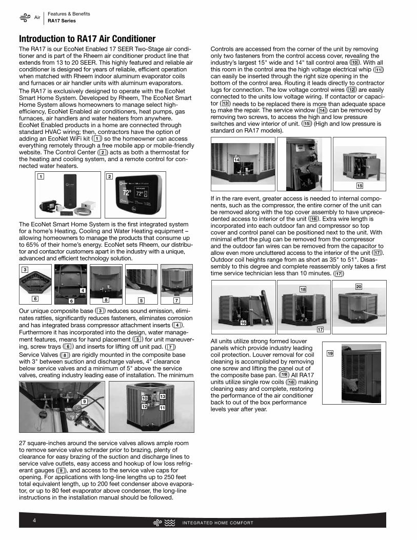
The RA17 is our EcoNet Enabled 17 SEER Two-Stage air condi-tioner and is part of the Rheem air conditioner product line thatextends from 13 to 20 SEER. This highly featured and reliable airconditioner is designed for years of reliable, efficient operationwhen matched with Rheem indoor aluminum evaporator coilsand furnaces or air handler units with aluminum evaporators.The RA17 is exclusively designed to operate with the EcoNetSmart Home System. Developed by Rheem, The EcoNet SmartHome System allows homeowners to manage select high-efficiency, EcoNet Enabled air conditioners, heat pumps, gasfurnaces, air handlers and water heaters from anywhere.EcoNet Enabled products in a home are connected throughstandard HVAC wiring; then, contractors have the option ofadding an EcoNet WiFi kit ( ) so the homeowner can accesseverything remotely through a free mobile app or mobile-friendlywebsite. The Control Center ( ) acts as both a thermostat forthe heating and cooling system, and a remote control for con-nected water heaters.
The EcoNet Smart Home System is the first integrated systemfor a home’s Heating, Cooling and Water Heating equipment –allowing homeowners to manage the products that consume upto 65% of their home’s energy. EcoNet sets Rheem, our distribu-tor and contactor customers apart in the industry with a unique,advanced and efficient technology solution.
Our unique composite base ( ) reduces sound emission, elimi-nates rattles, significantly reduces fasteners, eliminates corrosionand has integrated brass compressor attachment inserts ( ).Furthermore it has incorporated into the design, water manage -ment features, means for hand placement ( ) for unit maneuver-ing, screw trays ( ) and inserts for lifting off unit pad. ( )Service Valves ( ) are rigidly mounted in the composite basewith 3" between suction and discharge valves, 4" clearancebelow service valves and a minimum of 5" above the servicevalves, creating industry leading ease of installation. The minimum
27 square-inches around the service valves allows ample roomto remove service valve schrader prior to brazing, plenty ofclearance for easy brazing of the suction and discharge lines toservice valve outlets, easy access and hookup of low loss refrig-erant gauges ( ), and access to the service valve caps foropening. For applications with long-line lengths up to 250 feettotal equivalent length, up to 200 feet condenser above evapora-tor, or up to 80 feet evaporator above condenser, the long-lineinstructions in the installation manual should be followed.
Controls are accessed from the corner of the unit by removingonly two fasteners from the control access cover, revealing theindustry’s largest 15" wide and 14" tall control area ( ). With allthis room in the control area the high voltage electrical whip ( )can easily be inserted through the right size opening in the bottom of the control area. Routing it leads directly to contractorlugs for connection. The low voltage control wires ( ) are easilyconnected to the units low voltage wiring. If contactor or capaci-tor ( ) needs to be replaced there is more than adequate spaceto make the repair. The service window ( ) can be removed byremoving two screws, to access the high and low pressureswitches and view interior of unit. ( ) (High and low pressure isstandard on RA17 models).
If in the rare event, greater access is needed to internal compo-nents, such as the compressor, the entire corner of the unit canbe removed along with the top cover assembly to have unprece-dented access to interior of the unit ( ). Extra wire length isincorporated into each outdoor fan and compressor so topcover and control panel can be positioned next to the unit. Withminimal effort the plug can be removed from the compressorand the outdoor fan wires can be removed from the capacitor toallow even more uncluttered access to the interior of the unit ( ).Outdoor coil heights range from as short as 35" to 51". Disas-sembly to this degree and complete reassembly only takes a firsttime service technician less than 10 minutes. ( )
All units utilize strong formed louverpanels which provide industry leadingcoil protection. Louver removal for coilcleaning is accomplished by removingone screw and lifting the panel out of the composite base pan. ( ) All RA17units utilize single row coils ( ) makingcleaning easy and complete, restoringthe performance of the air conditionerback to out of the box performancelevels year after year.
3
4
5
6
9
8
7
1
2
10
11
12
13
14
15
16
17
17
19
18
AirFeatures & BenefitsRA17 Series
4
Introduction to RA17 Air Conditioner
3
6 6 5 7
4
10 13
1112
15
14
18
16
20
17
9
19
8
21
AirFeatures & BenefitsRA17 Series
5
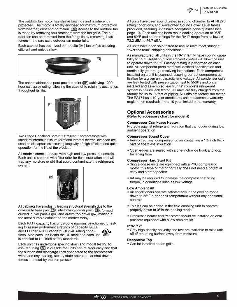
The outdoor fan motor has sleeve bearings and is inherentlyprotected. The motor is totally enclosed for maximum protectionfrom weather, dust and corrosion. ( ) Access to the outdoor fanis made by removing four fasteners from the fan grille. The out-door fan can be removed from the fan grille by removing 4 fas-teners in the rare case outdoor fan motor fails. Each cabinet has optimized composite ( ) fan orifice assuringefficient and quiet airflow.
The entire cabinet has post powder paint ( ) achieving 1000hour salt spray rating, allowing the cabinet to retain its aestheticsthroughout its life.
Two Stage Copeland Scroll™ UltraTech™ compressors with standard internal pressure relief and internal thermal overload areused on all capacities assuring longevity of high efficient and quietoperation for the life of the product.
All models come standard with high and low pressure controls.Each unit is shipped with filter drier for field installation and willtrap any moisture or dirt that could contaminate the refrigerantsystem.
All cabinets have industry leading structural strength due to thecomposite base pan ( ), interlocking corner post ( ), formedcurved louver panels ( ) and drawn top cover ( ) making itthe most durable cabinet on the market today.
Each RA17 capacity has undergone rigorous psychometric test-ing to assure performance ratings of capacity, SEERand EER per AHRI Standard 210/240 rating condi-tions. Also each unit bears the UL mark and each unitis certified to UL 1995 safety standards.
Each unit has undergone specific strain and modal testing toassure tubing ( ) is outside the units natural frequency and thatthe suction and discharge lines connected to the compressorwithstand any starting, steady state operation, or shut downforces imposed by the compressor.
All units have been sound tested in sound chamber to AHRI 270rating conditions, and A-weighted Sound Power Level tablesproduced, assuring units have acceptable noise qualities (seepage 10). Each unit has been ran in cooling operation at 95°Fand 82°F and sound ratings for the RA17 range from as low as72.3 dBA to 76.7 dBA.
All units have been ship tested to assure units meet stringent“over the road” shipping conditions.
As manufactured, all units in the RA17 family have cooling capa-bility to 55 °F. Addition of low ambient control will allow the unitto operate down to 0°F. Factory testing is performed on eachunit. All component parts meet well defined specification andcontinually go through receiving inspections. Each componentinstalled on a unit is scanned, assuring correct component uti-lization for a given unit capacity and voltage. All condenser coilsare leak tested with pressurization test to 550#’s and onceinstalled and assembled, each units’ complete refrigerant system is helium leak tested. All units are fully charged from thefactory for up to 15 feet of piping. All units are factory run tested.The RA17 has a 10-year conditional unit replacement warranty(registration required) and a 10 year limited parts warranty.
Optional Accessories(Refer to accessory chart for model #)
Compressor Crankcase HeaterProtects against refrigerant migration that can occur during lowambient operation
Compressor Sound Cover• Reinforced vinyl compressor cover containing a 1½ inch thick
batt of fiberglass insulation
• Open edges are sealed with a one-inch wide hook and loopfastening tape
Compressor Hard Start Kit• Single-phase units are equipped with a PSC compressor
motor, this type of motor normally does not need a potentialrelay and start capacitor
• Kit may be required to increase the compressor startingtorque, in conditions such as low voltage
Low Ambient Kit• Air conditioners operate satisfactorily in the cooling mode
down to 55°F outdoor air temperature without any additionalcontrols
• This Kit can be added in the field enabling unit to operateproperly down to 0° in the cooling mode
• Crankcase heater and freezestat should be installed on com-pressors equipped with a low ambient kit
3"/6"/12"• Gray high density polyethylene feet are available to raise unit
off of mounting surface away from moisture
Decorative Top• Can be installed on fan grille
27
2423
2625
22
20
21
22
26
25
2423
27
21
AirFeatures & BenefitsRA17 Series
6
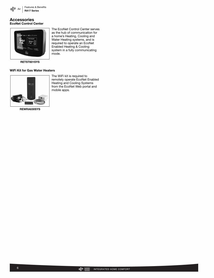
AccessoriesEcoNet Control Center
The EcoNet Control Center servesas the hub of communication fora home’s Heating, Cooling andWater Heating systems, and isrequired to operate an EcoNetEnabled Heating & Cooling system in a fully communicatingmode.
WiFi Kit for Gas Water Heaters
The WiFi kit is required toremotely operate EcoNet EnabledHeating and Cooling Systemsfrom the EcoNet Web portal andmobile apps.
RETST601SYS
REWRA630SYS

AirModel Number IdentificationRA17 Series
7
RA
1724
AJ
2C
B*
Bran
dPr
oduc
tCa
tego
rySE
ERCa
paci
tyBT
U/HR
Maj
or S
erie
s*Vo
ltage
Type
Cont
rols
Min
or S
erie
s**
Optio
n Co
deRh
eem
A -
Air C
ondi
tione
rs
13 -
13 S
EER
14 -
14 S
EER
16 -
16 S
EER
17 -
17 S
EER
20 -
20 S
EER
18 -
18,0
00
[5.2
8 kW
]24
- 24
,000
[7
.03
kW]
30 -
30,0
00
[8.7
9 kW
]36
- 36
,000
[10.
55 k
W]
42 -
42,0
00 [1
2.31
kW
]48
- 48
,000
[14.
07 k
W]
60 -
60,0
00 [1
7.58
kW
]
A - 1
st D
esig
nB
- 2nd
Des
ign
J - 1
ph, 2
08-2
30/6
0C
- 3ph
, 208
-230
/60
1 - S
ingl
e-st
age
2 - T
wo-
stag
eV
- Inv
erte
r
C - C
omm
unic
atin
gN
- Non
-Com
mun
icat
ing
A - 1
st D
esig
nB
- Hig
han
d lo
w
pres
sure
cont
rol
N/A
RP
1724
AJ
VC
A*
Bran
dPr
oduc
tCa
tego
rySE
ERCa
paci
tyBT
U/HR
Maj
or S
erie
s*Vo
ltage
Type
Cont
rols
Min
or S
erie
s**
Optio
n Co
deRh
eem
P
- Hea
t Pum
p 13
- 13
SEE
R14
- 14
SEE
R15
- 15
SEE
R17
- 17
SEE
R20
- 20
SEE
R
18 -
18,0
00
[5.2
8 kW
]24
- 24
,000
[7
.03
kW]
30 -
30,0
00
[8.7
9 kW
]36
- 36
,000
[10.
55 k
W]
42 -
42,0
00 [1
2.31
kW
]48
- 48
,000
[14.
07 k
W]
60 -
60,0
00 [1
7.58
kW
]
A - 1
st D
esig
nJ
- 1ph
, 208
-230
/60
C - 3
ph, 2
08-2
30/6
0D
- 3ph
, 460
/60
1 - S
ingl
e-st
age
2 - T
wo-
stag
eV
- Inv
erte
rP
- Pis
ton
C - C
omm
unic
atin
gN
- Non
-Com
mun
icat
ing
A - 1
st D
esig
nN/
A
RC
F24
17S
EA
MC
A*
Bran
dPr
oduc
tCa
tego
ryTy
peCa
paci
tyBT
U/HR
Wid
thEf
ficie
ncy
Met
erin
gDe
vice
Maj
orSe
ries*
Orie
ntat
ion
Casi
ngM
inor
Ser
ies*
*Op
tion
Code
Rhee
m
C - E
vap
Coil
F - F
urn
Coil
H - A
ir-Ha
ndle
rCo
il
24 -
24,0
00
[7.0
3 kW
]36
- 36
,000
[10.
55 k
W]
48 -
48,0
00 [1
4.07
kW
]60
- 60
,000
[17.
58 k
W]
14 -
14"
17 -
17.5
"21
- 21
"24
- 24
.5"
S- S
tand
ard
Eff.
M- M
id E
ff.H-
Hig
h Ef
f.
T-TX
VE-
EEV
P-Pi
ston
A - 1
st D
esig
nM
- M
ultip
oise
V - V
ertic
al o
nly/
conv
ertib
leH
- Ded
.Ho
rizon
tal o
nly
C - C
ased
U - U
ncas
edA
- 1st
Des
ign
N/A
Heat
Pum
ps (F
or R
efer
ence
)
Furn
ace
Coils
(For
Ref
eren
ce)
Air C
ondi
tione
rs
[ ]
Des
igna
tes
Met
ric
Co
nver
sio
ns

AirModel Number IdentificationRA17 Series
8
R96
VA
702
317
MS
A
Bran
dSe
ries
Mot
orM
ajor
Rev
Inpu
tBT
U/HR
Stag
esAi
r Flo
wCa
bine
tW
idth
Conf
igur
atio
nNo
xM
inor
Rev
Rhee
m
90 -
90 A
FUE
92 -
92 A
FUE
95 -
95 A
FUE
96 -
96 A
FUE
97 -
97 A
FUE
V - V
aria
ble
spee
dT
- Con
stan
tTo
rque
(X-1
3)P
- PSC
A - 1
st D
esig
n04
0 -
42,0
00 [1
2.31
kW
]06
0 -
56,0
00 [1
6.41
kW
]07
0 -
70,0
00 [2
0.51
kW
]08
5 -
84,0
00 [2
4.62
kW
]10
0 -
98,0
00 [2
8.72
kW
]11
5 - 1
12,0
00 [3
2.82
kW
]
1-S
ingl
e-st
age
2-T
wo-
stag
eM
- M
odul
atin
g
3 - u
p to
3 to
n5
- 3 1
/2 u
p to
5 to
n14
- 14
"17
- 17
.5"
21 -
21"
24 -
24.5
"
M -
Mul
tiX
- Low
Nox
S - S
tand
ard
A - 1
st D
esig
n
R80
2V
A07
53
17M
SA
Bran
dSe
ries
Stag
esM
otor
Maj
or R
evIn
put
BTU/
HRAi
r Flo
wCa
bine
tW
idth
Conf
igur
atio
nNo
xM
inor
Rev
Rhee
m
80 -
80+
AFUE
1- S
ingl
e-st
age
2- T
wo-
stag
eV
- Var
iabl
e sp
eed
T - C
onst
ant T
orqu
e (X
-13)
P - P
SC p
rem
ium
S - P
SC s
tand
ard
A - 1
st D
esig
n05
0 -
50,0
00 [1
5 kW
]07
5 -
75,0
00 [2
2 kW
]10
0 - 1
00,0
00 [2
9 kW
]12
5 - 1
25,0
00 [3
7 kW
]15
0 - 1
50,0
00 [4
4 kW
]
3 - u
p to
3 to
n4
- 2 1
/2 to
4 to
n5
- 3 1
/2 u
p to
5 to
n
14 -
14"
17 -
17.5
"21
- 21
"24
- 24
.5"
M- M
ulti
D- D
own
Z- D
own
&ze
ro c
lear
ance
dow
n flo
w
X - L
ow N
oxS
- Sta
ndar
dA
- 1st
Des
ign
RH
2T
3617
SE
AC
AA
000
*
Bran
dPr
oduc
tCa
tego
rySt
ages
of
Airfl
owM
otor
Typ
eCa
paci
tyBT
U/HR
Wid
thCo
il Si
zeM
eter
ing
Devi
ceM
ajor
Serie
s*Co
ntro
lsVo
ltage
Min
orSe
ries*
*Fa
ctor
y He
atCa
pOp
tion
Code
Rhee
m
H - A
irHa
ndle
r1
- Sin
gle-
Stag
e2
- Tw
o-St
age
M -
Mod
ulat
ing
V - V
aria
ble
Spee
dT
- Con
stan
tTo
rque
P - P
SC
24 -
24,0
00
[7.0
3 kW
]36
- 36
,000
[10.
55 k
W]
48 -
48,0
00 [1
4.07
kW
]60
- 60
,000
[17.
58 k
W]
14 -
14"
17 -
17.5
"21
- 21
"24
- 24
.5"
S - S
tand
ard
Eff.
M -
Mid
Eff.
H - H
igh
Eff.
T - T
EVE
- EEV
P - P
isto
n
A - 1
st D
esig
nC
-Com
mun
icat
ing
N -N
on-c
omm
A - 1
ph, 1
15/6
0J
- 1ph
, 208
-240
/60
D - 3
ph, 4
80/6
0
A - 1
st D
esig
n00
- no
fact
ory
heat
with
opt
ion
code
*TBD
90%
+ A
FUE
Gas
Furn
aces
(For
Ref
eren
ce)
80%
AFU
E Ga
s Fu
rnac
es (F
or R
efer
ence
)
Air H
andl
ers
(For
Ref
eren
ce)
[ ]
Des
igna
tes
Met
ric
Co
nver
sio
ns

AirGeneral Data/Electrical DataRA17 Series
9
Physical DataModel No. RA1724A RA1736A RA1748A RA1760ANominal Tonnage 2.0 3.0 4.0 5.0Valve Connections
Liquid Line O.D. – in. 3/8 3/8 3/8 3/8Suction Line O.D. – in. 3/4 3/4 7/8 7/8
Refrigerant (R-410A) furnished oz.¹ 128 151 204 223Compressor Type ScrollOutdoor Coil
Net face area – Outer Coil 19.8 22.2 32.3 32.3Net face area – Inner Coil — — — —
Tube diameter – in. 0.375 0.375 0.375 0.375Number of rows 1 1 1 1
Fins per inch 20 22 22 22Outdoor Fan
Diameter – in. 24 24 26 26Number of blades 3 3 3 3
Motor hp 1/5 1/5 1/2 1/2CFM 3326 3540 4251 5133RPM 850 820 646 825watts 112 112 132 113
Shipping weight – lbs. 200 209 297 298Operating weight – lbs. 193 202 290 291
Electrical DataLine Voltage Data (Volts-Phase-Hz) 208/230-1-60 208/230-1-60 208/230-1-60 208/230-1-60
Maximum overcurrent protection (amps)² 25 35 50 70Minimum circuit ampacity³ 16 21 32 42Compressor
Rated load amps 11.7 15.3 21.2 28.8Locked rotor amps 58.3 83 104 152.9
Condenser Fan MotorFull load amps 1.4 1.2 5.3 5.3
Locked rotor amps — — — —
¹Refrigerant charge sufficient for 15 ft. length of refrigerant lines. For longer line set requirements see the installation instructions for information about set length and additionalrefrigerant charge required.
²HACR type circuit breaker of fuse.³Refer to National Electrical Code manual to determine wire, fuse and disconnect size requirements.

AirAccessories/Weighted Sound PowerRA17 Series
10
AccessoriesModel No. RA1724 RA1736 RA1748 RA1760
EcoNet Control Center RETST601SYS RETST601SYS RETST601SYS RETST601SYS
WiFi Kit for Heating & Cooling REWRA630SYS REWRA630SYS REWRA630SYS REWRA630SYS
Compressor crankcase heater* 44-17402-49 44-17402-49 44-101884-05 44-101884-05
Low ambient control RXAD-A08 RXAD-A08 RXAD-A08 RXAD-A08
Freeze Stat 50313 50313 50313 50313
Compressor sound cover 68-23427-26 68-23427-26 68-25217-10 68-25217-10
Compressor hard start kit SK-A1 SK-A1 SK-A1 SK-A1
Heat pump Riser 6 in. 686020 686020 686020 686020
Liquid Line Solenoid(24 VAC, 50/60 Hz)
Solenoid Valve 200RD2T3TVLC 200RD2T3TVLC 200RD3T3TVLC 200RD3T3TVLC
Solenoid Coil 61-AMG24V 61-AMG24V 61-AMG24V 61-AMG24V
Liquid Line Solenoid(120/240 VAC, 50/60 Hz)
Solenoid Valve 200RD2T3TVLC 200RD2T3TVLC 200RD3T3TVLC 200RD3T3TVLC
Solenoid Coil 61-AMG120/240V 61-AMG120/240V 61-AMG120/240V 61-AMG120/240V
*Crankcase Heater recommended with Low Ambient Kit.
Weighted Sound Power Level (dBA)Unit Size - Voltage, Series Standard
Rating (dBA)TYPICAL OCTAVE BAND SPECTRUM (dBA without tone adjustment)
125 250 500 1000 2000 4000 8000
RA1724A 72.5 48.6 53.7 62.9 63.0 60.5 57.3 54.6RA1736A 72.3 53.1 52.7 60.9 62.4 61.2 58.4 51.6RA1748A 73.0 46.1 50.4 59.5 64.6 59.6 55.8 54.6RA1760A 76.7 58.8 60.5 65.6 65.2 62.9 62.4 55.5
NOTE: Tested in accordance with AHRI Standard 270-08 (not listed in AHRI)

AirSmart Home SystemsRA17 Series
11
Easy to Setup, Easy to Use, Easy to Save
• Built with our 360°+1 design philosophy, itis optimized for Installability™, Performance,Integration & Serviceability
• Controls 65%† or more of a typical home’senergy use from a single device
• Can reduce energy costs by up to 30%††
Features• Added support for new EEV (Electronic
Expansion Valve) Air Handlers, Air Condi-tioners and Heat Pumps*
• Rapid installation with standard 4-wireconfiguration
• Automatically configures communicatingequipment with optimal settings
• Adapts to home décor throughinterchangeable faceplates and adjustablebackground coloring
• Full-color, 4.7" LCD touchscreen displaywith easy-to-read icons and text
• Convenient date, time and indoor/outdoortemperature indications
• 5 operating modes with short-cycle protec-tion (Heat, Cool, Auto, Emergency Heat,Fan Only)
• 7-Day programmable schedule withSmooth Arrival & Whole Home Vacationoptions
• Detailed operating status, alarm history,and audible alerts
• Supports humidifier accessories or over-cool based dehumidification
• One-touch access to Water Heater Management†††
• Easily manage from anywhere in the worldwith the compatible WiFi Module & EcoNetapp for smart phones and tablets
Warranty• 5-Year limited warranty from date of
installation ††† Source – Department of Energy ††† When compared to non-programmable thermostats.
Source: ENERGY STAR® for ProgrammableThermostats
††† Requires wired connection to EcoNet Enabled Electricor Hybrid Water Heaters
Integrated Controls
EcoNet is smart, new technology developed exclusively by Rheem that allows Heating, Cooling,and Water Heating products to communicate with each other on one integrated network.
EcoNet™ Control CenterHome control with intuitive LCD
touchscreen navigation
RETST601SYS
EcoNet Control Center Compatibility
★ Comfort Control2 System™ Translator for EcoNet RequiredInstallation of the RETRN620CC2 Comfort Control2 System™ Translator on the outdoor unit’s control board is required to operate Comfort Control2 System™ Air Conditionerand Heat Pump models (****-JEC) with an EcoNet Control Center in a fully communicating mode when matched with EcoNet Enabled Furnaces or Air Handlers*.
OFFERINGS HEATING & COOLING
WiFi Kit forHVAC
REWRA630SYS
WATER HEATING
ProductCategories Gas Furnaces Air Handlers Air Conditioners Heat Pumps
ElectricTank
ModelsEnding in
EC2
HybridTank HB50
Models
GasPoweredDamper
TankModelsModels R96V R802V RHMV* RH2T*
(EEV**) RA20* RASL-JEC RA17 RARL-JEC RP20* RP17* RPRL-JEC
RETST601SYS √ √ √ √ √ √ ★ √ √ ★ √ √ √ ★ √ √ √
*Available in 2015**Electronic Expansion Valve (EEV) Models

AirSmart Home SystemsRA17 Series
12
Features
• Enables remote operation from:- The EcoNet App on Apple® mobile devices
(iPhone®, iPad®, & iPod® Touch) using iOSversion 7.0 or later
- The EcoNet App on Android™ based smartphones and tablets using Android™ version4.4 or later
- Recent versions of popular web browserssuch as Internet Explorer, Chrome, Safari,etc.
• Designed for use with EcoNet communi-cating HVAC Systems
• Compatible with 802.11 b/g/n WiFi networks• WPA-2 Security using AES/CCMP• Status LEDs:- Power & Equipment
Connection Status- Home Network WiFi Status- Internet Connection Status• “WLAN SETUP" factory reset button
WiFi Kit Components
• EcoNet WiFi Module• Installation Instructions• V Power Adapter• Junction Box
• 24" Port-to-Port Connection Cable• 1" x 2" Double Adhesive Mounting Tape• RJ12 Y Splitter (for use with
communicating electric water heaters)
Compatibility• Works with any HVAC System
which includes an EcoNet Enabled furnace or air handler and an EcoNet control center.
Warranty
• 1 Year from installation date
The EcoNet™ WiFi Kit for Heating & Cooling Systems(REWRA630SYS) provides remote control of EcoNetEnabled air and water products from smart phones,tablets, and personal computers using the home’sinternet connection.
EcoNet WiFi Kit for Heating& Cooling Systems
REWRA630SYS
HVAC Connection Illustration

AirUnit DimensionsRA17 Series
13
Unit Dimensions
MODELNO.
OPERATING SHIPPING
H (Height) L (Length) W (Width) H (Height) L (Length) W (Width)
INCHES mm INCHES mm INCHES mm INCHES mm INCHES mm INCHES mm
RA1724 35 889 33.75 857 33.75 857 36.75 933 36.38 924 36.38 924
RA1736 39 990 33.75 857 33.75 857 40.75 1035 36.38 924 36.38 924
RA1748 51 1295 35.75 908 35.75 908 52.75 1339 38.38 974 38.38 974
RA1760 51 1295 35.75 908 35.75 908 52.75 1339 38.38 974 38.38 974
[ ] Designates Metric Conversions ST-A1226-02-00
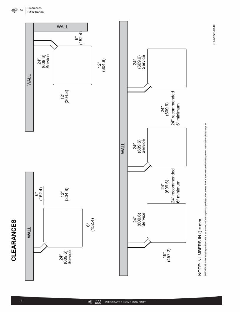
AirClearancesRA17 Series
14
6�
(152
.4)
24�
(609
.6)
Ser
vice
12�
(304
.8)
6�
(152
.4)
24�
(609
.6)
Ser
vice
24�
(609
.6)
24�
reco
mm
ende
d6�
min
imum
12�
(304
.8)
12�
(304
.8)
6�
(152
.4)
24�
(609
.6)
Ser
vice
24�
(609
.6)
Ser
vice
24�
(609
.6)
Ser
vice
18�
(457
.2)
WA
LL
WA
LL
WA
LLWALL
NO
TE
: NU
MB
ER
S IN
()
= m
m
CLEARANCES
IMPO
RTA
NT:
Whe
n in
stal
ling
mul
tiple
uni
ts in
an
alco
ve, r
oof w
ell o
r par
tially
enc
lose
d ar
ea, e
nsur
e th
ere
is a
dequ
ate
vent
illatio
n to
pre
vent
re-c
ircul
atio
n of
dis
char
ge a
ir.
ST-
A12
25-0
1-00
24�
(609
.6)
24�
reco
mm
ende
d6�
min
imum

AirWiring Diagram/Application GuidelinesRA17 Series
15
Indoor Unit
E1
E2
C
R
WIRING INFORMATIONLine Voltage –Field Installed - - - - - - –Factory Standard
E1 E2 R C
E1
E2
R
C
Communicating Thermostat
Outdoor Unit
FIGURE 2TYPICAL ECONET COMMUNICATING SYSTEM™ WIRING DIAGRAM
Application Guidelines1. Intended for outdoor installation with free air inlet and outlet. Outdoor fan external static pressure available is less than 0.01 -in. wc.
2. Minimum outdoor operation air temperature for cooling mode without low-ambient operation accessory is 55°F (12.8°C).
3. Maximum outdoor operating air temperature is 125°F (51.7°C).
4. For reliable operation, unit should be level in all horizontal planes.
5. Use only copper wire for electric connections at unit. Aluminum and clad aluminum are not acceptable for the type of connectorprovided.
6. Do not apply capillary tube indoor coils to these units.
7. Factory – supplied filter drier must be installed.
Control Wiring

AirWiring Diagram/Application GuidelinesRA17 Series
16
Conventional Thermostat Wiring
W2
W1
C
G
(-)HPN AirHandler
Y1
Typical Two-Stage Thermostat
(-)ARLCondensing
Unit
Y2
C
R
Y2
Field Installed Line Voltage
-
WIRING INFORMATION
Factory Standard -
ODD
R
Y1
Y2 G W2 R
Y1
C
L
Y
Y/BL
R
BR
W/R
W1
*
FIGURE TYPICAL 2-STAGE THERMOSTAT: CONDENSING UNIT WITHELECTRIC HEAT
FIGURE 4 TYPICAL TWO-STAGE THERMOSTAT: CONDENSING UNIT WITHELECTRIC HEAT USING A HUMIDISTAT FOR DEHUMIDIFICATION*.
W2
W1
C
G
(-)HPN AirHandler
Y1
Typical Two-Stage Thermostat
(-)ARLCondensing
Unit
Y2
C
R
Y2
Field Installed Line Voltage
-
WIRING INFORMATION
Factory Standard -
ODD
R
Y1
Y2 G W2 R
Y1
C
L
Y
Y/BL
R
BR
W/R
HumidistatW1
*
FIGURE 5TYPICAL TWO-STAGE THERMOSTAT: CONDENSING UNIT WITHELECTRIC HEAT USING A TWO-STAGE THERMOSTAT WITHDEHUMIDIFICATION*
W2
W1
C
G
(-)HPN AirHandler
Y1
Typical Two-Stage Thermostat
(-)ARLCondensing
Unit
Y2
C
R
Y2
Field Installed Line Voltage
-
WIRING INFORMATION
Factory Standard -
ODD
R
Y1
Y2 G W2 R
Y1
C
L
Y
Y/BL
R
BR
W/R
DHMW1
*W2
W1
C
G
(-)HPN AirHandler
Y1
Typical Two-Stage Thermostat
(-)ARLCondensing
Unit
Y2
C
RY2
Field Installed Line Voltage
-
WIRING INFORMATION
Factory Standard -
ODD
R
Y1
Y2 G W2 R
Y1
C
L
Y
Y/BL
R
BR
W/R
DHM LW1
*
FIGURE 6CONDENSING UNIT WITH ELECTRIC HEAT USING A TWO-STAGETHERMOSTAT WITH DEHUMIDIFICATION*
WIRE COLOR CODE
BK – BLACK G – GREEN PR – PURPLE Y – YELLOWBR – BROWN GY – GRAY R – REDBL – BLUE O – ORANGE W – WHITE
*See Section 5.11 for proper DIP switch selection.
The following figures show the typical wiring diagrams with (-)HPN air handler and (-)ARL con-densing unit. Cooling and heat pump airflows may need to be adjusted for homeowner comfortonce the system is operational.
*If maximum outlet temperature rise is desired, it is recommended that W1 and W2 be jumpered together.
3
Application Guidelines1. Intended for outdoor installation with free air inlet and outlet. Outdoor fan external static pressure available is less than 0.01 -in. wc. 2. Minimum outdoor operation air temperature for cooling mode without low-ambient operation accessory is 55°F (12.8°C). 3. Maximum outdoor operating air temperature is 125°F (51.7°C). 4. For reliable operation, unit should be level in all horizontal planes. 5. Use only copper wire for electric connections at unit. Aluminum and clad aluminum are not acceptable for the type of connector
provided. 6. Do not apply capillary tube indoor coils to these units.7. Factory – supplied filter drier must be installed.
Non-communicating Thermostat Wiring Diagrams
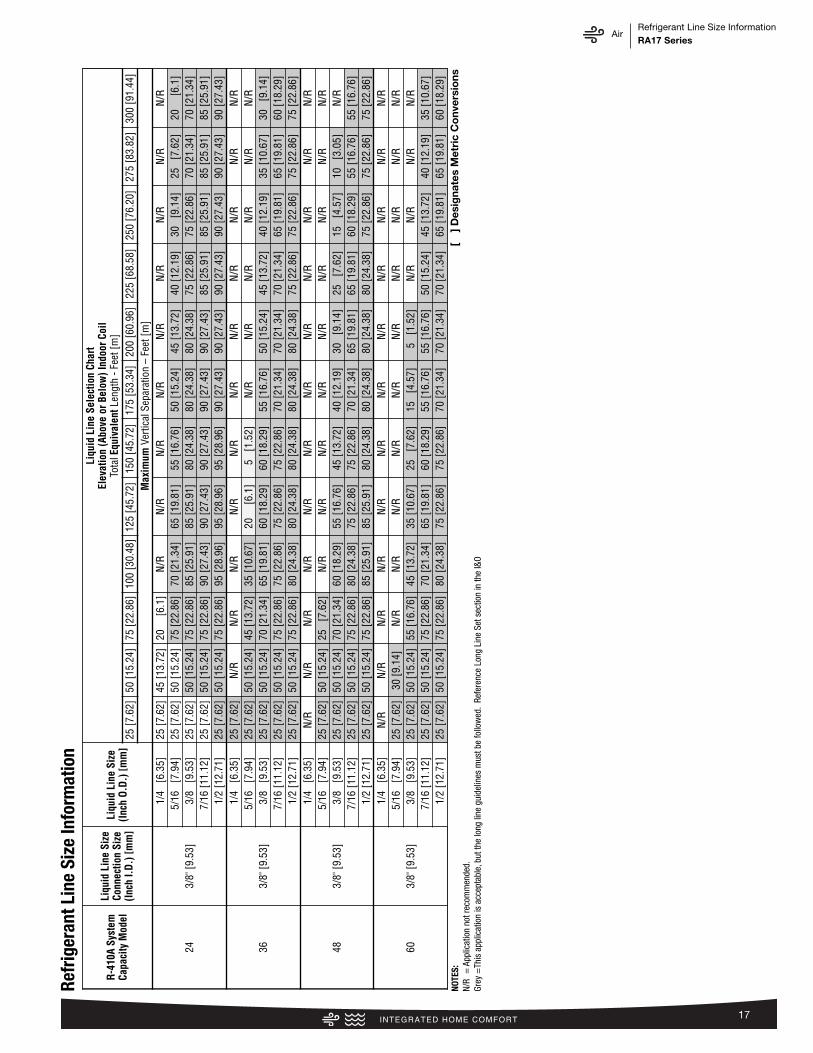
AirRefrigerant Line Size InformationRA17 Series
17
R-41
0A S
yste
mCa
paci
ty M
odel
Liqu
id L
ine
Size
Conn
ectio
n Si
ze(In
ch I.
D.) [
mm
]
Liqu
id L
ine
Size
(Inch
O.D
.) [m
m]
Liqu
id L
ine
Sele
ctio
n Ch
art
Elev
atio
n (A
bove
or B
elow
) Ind
oor C
oil
Tota
lEqu
ival
ent L
engt
h - F
eet [
m]
25 [7
.62]
50 [1
5.24
]75
[22.
86]
100
[30.
48]
125
[45.
72]
150
[45.
72]
175
[53.
34]
200
[60.
96]
225
[68.
58]
250
[76.
20]
275
[83.
82]
300
[91.
44]
Max
imum
Ver
tical
Sep
arat
ion
–Fe
et [m
]
243/
8" [9
.53]
1/4
[6.
35]
25 [7
.62]
45 [1
3.72
]20
[
6.1]
N/R
N/R
N/R
N/R
N/R
N/R
N/R
N/R
N/R
5/16
[7
.94]
25 [7
.62]
50 [1
5.24
]75
[22.
86]
70 [2
1.34
]65
[19.
81]
55 [1
6.76
]50
[15.
24]
45 [1
3.72
]40
[12.
19]
30
[9.1
4]25
[7
.62]
20
[6.
1]3/
8 [9
.53]
25 [7
.62]
50 [1
5.24
]75
[22.
86]
85 [2
5.91
]85
[25.
91]
80 [2
4.38
]80
[24.
38]
80 [2
4.38
]75
[22.
86]
75 [2
2.86
]70
[21.
34]
70 [2
1.34
]7/
16 [1
1.12
]25
[7.6
2]50
[15.
24]
75 [2
2.86
]90
[27.
43]
90 [2
7.43
]90
[27.
43]
90 [2
7.43
]90
[27.
43]
85 [2
5.91
]85
[25.
91]
85 [2
5.91
]85
[25.
91]
1/2
[12.
71]
25 [7
.62]
50 [1
5.24
]75
[22.
86]
95 [2
8.96
]95
[28.
96]
95 [2
8.96
]90
[27.
43]
90 [2
7.43
]90
[27.
43]
90 [2
7.43
]90
[27.
43]
90 [2
7.43
]
363/
8" [9
.53]
1/4
[6.
35]
25 [7
.62]
N/R
N/R
N/R
N/R
N/R
N/R
N/R
N/R
N/R
N/R
N/R
5/16
[7
.94]
25 [7
.62]
50 [1
5.24
]45
[13.
72]
35 [1
0.67
]20
[
6.1]
5 [
1.52
]N
/RN
/RN
/RN
/RN
/RN
/R3/
8 [9
.53]
25 [7
.62]
50 [1
5.24
]70
[21.
34]
65 [1
9.81
]60
[18.
29]
60 [1
8.29
]55
[16.
76]
50 [1
5.24
]45
[13.
72]
40 [1
2.19
]35
[10.
67]
30
[9.1
4]7/
16 [1
1.12
]25
[7.6
2]50
[15.
24]
75 [2
2.86
]75
[22.
86]
75 [2
2.86
]75
[22.
86]
70 [2
1.34
]70
[21.
34]
70 [2
1.34
]65
[19.
81]
65 [1
9.81
]60
[18.
29]
1/2
[12.
71]
25 [7
.62]
50 [1
5.24
]75
[22.
86]
80 [2
4.38
]80
[24.
38]
80 [2
4.38
]80
[24.
38]
80 [2
4.38
]75
[22.
86]
75 [2
2.86
]75
[22.
86]
75 [2
2.86
]
483/
8" [9
.53]
1/4
[6.
35]
N/R
N/R
N/R
N/R
N/R
N/R
N/R
N/R
N/R
N/R
N/R
N/R
5/16
[7
.94]
25 [7
.62]
50 [1
5.24
]25
[7
.62]
N/R
N/R
N/R
N/R
N/R
N/R
N/R
N/R
N/R
3/8
[9.5
3]25
[7.6
2]50
[15.
24]
70 [2
1.34
]60
[18.
29]
55 [1
6.76
]45
[13.
72]
40 [1
2.19
]30
[9
.14]
25
[7.6
2]15
[4
.57]
10
[3.0
5]N
/R7/
16 [1
1.12
]25
[7.6
2]50
[15.
24]
75 [2
2.86
]80
[24.
38]
75 [2
2.86
]75
[22.
86]
70 [2
1.34
]65
[19.
81]
65 [1
9.81
]60
[18.
29]
55 [1
6.76
]55
[16.
76]
1/2
[12.
71]
25 [7
.62]
50 [1
5.24
]75
[22.
86]
85 [2
5.91
]85
[25.
91]
80 [2
4.38
]80
[24.
38]
80 [2
4.38
]80
[24.
38]
75 [2
2.86
]75
[22.
86]
75 [2
2.86
]
603/
8" [9
.53]
1/4
[6.
35]
N/R
N/R
N/R
N/R
N/R
N/R
N/R
N/R
N/R
N/R
N/R
N/R
5/16
[7
.94]
25 [7
.62]
30 [9
.14]
N/R
N/R
N/R
N/R
N/R
N/R
N/R
N/R
N/R
N/R
3/8
[9.5
3]25
[7.6
2]50
[15.
24]
55 [1
6.76
]45
[13.
72]
35 [1
0.67
]25
[7
.62]
15
[4.5
7]5
[1.
52]
N/R
N/R
N/R
N/R
7/16
[11.
12]
25 [7
.62]
50 [1
5.24
]75
[22.
86]
70 [2
1.34
]65
[19.
81]
60 [1
8.29
]55
[16.
76]
55 [1
6.76
]50
[15.
24]
45 [1
3.72
]40
[12.
19]
35 [1
0.67
]1/
2 [1
2.71
]25
[7.6
2]50
[15.
24]
75 [2
2.86
]80
[24.
38]
75 [2
2.86
]75
[22.
86]
70 [2
1.34
]70
[21.
34]
70 [2
1.34
]65
[19.
81]
65 [1
9.81
]60
[18.
29]
Refr
iger
ant L
ine
Size
Info
rmat
ion
NOTE
S:[
] D
esig
nate
s M
etri
c C
onv
ersi
ons
N/R
= A
pplic
atio
n no
t rec
omm
ende
d.Gr
ey=
This
app
licat
ion
is a
ccep
tabl
e, b
ut th
e lo
ng li
ne g
uide
lines
mus
t be
follo
wed
. Re
fere
nce
Long
Lin
e Se
t sec
tion
in th
e I&
O

AirRefrigerant Line Size InformationRA17 Series
18
R-41
0A S
yste
mCa
paci
ty M
odel
Vapo
r Lin
eCo
nnec
tion
Size
(Inch
I.D.
) [m
m]
Vapo
r Lin
e Si
ze(In
ch O
.D.)
[mm
]
Vapo
r Lin
e Se
lect
ion
Char
tCa
paci
ty M
ultip
lier T
able
Tota
lEqu
ival
ent L
engt
h - F
eet [
m]
25 [7
.62]
50 [1
5.24
]75
[22.
86]
100
[30.
48]
125
[45.
72]
150
[45.
72]
175
[53.
34]
200
[60.
96]
225
[68.
58]
250
[76.
20]
275
[83.
82]
300
[91.
44]
243/
4" [1
9.06
]
5/8
[15.
88]
0.99
1.00
0.97
0.98
0.98
0.96
0.96
0.95
0.94
0.95
0.94
0.93
3/4
[19.
05]
1.00
1.00
0.99
0.99
0.98
1.00
0.99
0.99
0.99
0.97
0.98
0.98
7/8
[22.
23]
1.01
1.01
1.00
1.00
1.00
0.99
0.99
0.99
0.99
0.99
0.99
0.99
1 [
25.4
]N
/RN
/RN
/RN
/RN
/RN
/RN
/RN
/RN
/RN
/RN
/RN
/R1-
1/8
[28.
58]
N/R
N/R
N/R
N/R
N/R
N/R
N/R
N/R
N/R
N/R
N/R
N/R
363/
4" [1
9.06
]
5/8
[15.
88]
0.99
0.98
0.97
0.95
0.95
0.93
0.91
0.91
0.90
0.88
0.87
0.86
3/4
[19.
05]
1.00
0.99
0.99
0.99
0.98
0.98
0.97
0.97
0.96
0.96
0.95
0.95
7/8
[22.
23]
1.01
1.00
1.00
1.00
0.99
0.99
0.99
0.99
0.99
0.99
0.99
0.99
1 [
25.4
]1.
011.
011.
011.
001.
001.
001.
001.
001.
001.
001.
001.
001-
1/8
[28.
58]
N/R
N/R
N/R
N/R
N/R
N/R
N/R
N/R
N/R
N/R
N/R
N/R
483/
4" [1
9.06
]
5/8
[15.
88]
0.97
0.96
0.93
0.91
0.89
0.88
0.87
0.85
0.83
0.82
0.82
N/R
3/4
[19.
05]
0.99
0.98
0.98
0.96
0.96
0.95
0.94
0.94
0.93
0.92
0.92
N/R
7/8
[22.
23]
1.00
1.00
0.99
0.99
0.98
0.98
0.98
0.97
0.97
0.96
0.96
N/R
1 [
25.4
]N
/RN
/RN
/RN
/RN
/RN
/RN
/RN
/RN
/RN
/RN
/RN
/R1-
1/8
[28.
58]
N/R
N/R
N/R
N/R
N/R
N/R
N/R
N/R
N/R
N/R
N/R
N/R
603/
4" [1
9.06
]
5/8
[15.
88]
0.96
0.93
0.91
0.88
0.86
0.84
0.83
0.83
N/R
N/R
N/R
N/R
3/4
[19.
05]
0.99
0.97
0.96
0.95
0.94
0.93
0.92
0.91
N/R
N/R
N/R
N/R
7/8
[22.
23]
1.00
0.99
0.98
0.98
0.97
0.97
0.96
0.96
N/R
N/R
N/R
N/R
1 [
25.4
]N
/RN
/RN
/RN
/RN
/RN
/RN
/RN
/RN
/RN
/RN
/RN
/R1-
1/8
[28.
58]
N/R
N/R
N/R
N/R
N/R
N/R
N/R
N/R
N/R
N/R
N/R
N/R
Refr
iger
ant L
ine
Size
Info
rmat
ion
(con
’t.)
NOTE
S:[
] D
esig
nate
s M
etri
c C
onv
ersi
ons
N/R
= A
pplic
atio
n no
t rec
omm
ende
d.Al
l cal
cula
tions
ass
ume
a 3/
8" li
quid
line

AirPerformance DataRA17 Series
19
Performance Data @ AHRI Standard Conditions – CoolingHigh Sales Volume Tested Combination (HSVTC)
Outdoor Unit Indoor Coilor Air Handler
Total CapacityBTU/H [kW]
Net SensibleBTU/H [kW]
Net LatentBTU/H [kW] SEER EER Indoor
CFM [L/s] AHRI#
RA1724AJ2 RH2T2421MEAC 24000 [7.0] 17100 [5.0] 6900 [2.0] 17.00 13.00 700 [330.4] 8231639
RA1736AJ2 RH2T3621MEAC 36000 [10.6] 26000 [7.6] 10000 [2.9] 17.00 13.00 1050 [495.5] 8231642
RA1748AJ2 RH2T4821MEAC 47000 [13.8] 34000 [10.0] 13000 [3.8] 17.00 13.00 1400 [660.7] 8231644
RA1760AJ2 RH2T6024MEAC 56000 [16.4] 39300 [11.5] 16700 [4.9] 16.00 12.50 1550 [731.5] 8231646
Coil Only Ratings
Outdoor Unit Indoor Coil Total CapacityBTU/H [kW]
Net SensibleBTU/H [kW]
Net LatentBTU/H [kW] SEER EER Indoor
CFM [L/s] AHRI#
RA1724AJ2 RCF2421MEAM+RXMD-C04 24000 [7.0] 17100 [5.0] 6900 [2.0] 15.10 12.50 800 [377.6] 8234324
RA1736AJ2RCF3621MEAM+RXMD-C04 36000 [10.6] 26000 [7.6] 10000 [2.9] 15.10 12.50 1200 [566.3] 8231640
RCF6021SEAM+RXMD-C04 36000 [10.6] 26000 [7.6] 10000 [2.9] 15.50 12.50 1200 [566.3] 8231641
RA1748AJ2 RCF6021SEAM+RXMD-C04 48000 [14.1] 34600 [10.1] 13400 [3.9] 15.50 12.50 1550 [731.5] 8231643
RA1760AJ2 RCF6024MEAM+RXMD-C04 55500 [16.3] 38100 [11.2] 17400 [5.1] 14.50 11.70 1600 [755.1] 8231645
R802V: Prestige 2-Stage 80% ECM Furnace Ratings
Outdoor Unit Furnace Indoor Coil Total CapacityBTU/H [kW]
Net SensibleBTU/H [kW]
Net LatentBTU/H [kW] SEER EER Indoor
CFM [L/s] AHRI#
RA1724AJ2 R802VA050317MSA RCF2421MEAM 24000 [7.0] 17100 [5.0] 6900 [2.0] 17.00 13.00 725 [342.2] 8234319
RA1724AJ2 R802VA075317MSA RCF2421MEAM 24000 [7.0] 17100 [5.0] 6900 [2.0] 17.00 13.00 675 [318.6] 8234320
RA1724AJ2 R802VA075317ZSA RCF2421MEAM 24000 [7.0] 17100 [5.0] 6900 [2.0] 17.00 13.00 725 [342.2] 8234321
RA1736AJ2 R802VA075317MSARCF3621MEAM 36000 [10.6] 26000 [7.6] 10000 [2.9] 17.00 13.00 1075 [507.3] 8232069
RCF6021SEAM 36000 [10.6] 26000 [7.6] 10000 [2.9] 17.00 13.00 1075 [507.3] 8232078
RA1736AJ2 R802VA075317ZSARCF3621MEAM 36000 [10.6] 26000 [7.6] 10000 [2.9] 17.00 13.00 1050 [495.5] 8232070
RCF6021SEAM 36000 [10.6] 26000 [7.6] 10000 [2.9] 17.00 13.00 1050 [495.5] 8232079
RA1736AJ2 R802VA075421ZSARCF3621MEAM 36000 [10.6] 26000 [7.6] 10000 [2.9] 17.00 13.00 1075 [507.3] 8232071
RCF6021SEAM 36000 [10.6] 26000 [7.6] 10000 [2.9] 17.00 13.00 1075 [507.3] 8232080
RA1736AJ2 R802VA100521MSARCF3621MEAM 36000 [10.6] 26000 [7.6] 10000 [2.9] 17.00 13.00 1025 [483.7] 8232072
RCF6021SEAM 36000 [10.6] 26000 [7.6] 10000 [2.9] 17.00 13.00 1025 [483.7] 8232081
RA1736AJ2 R802VA100521ZSARCF3621MEAM 36000 [10.6] 26000 [7.6] 10000 [2.9] 16.50 13.00 1050 [495.5] 8232073
RCF6021SEAM 36000 [10.6] 26000 [7.6] 10000 [2.9] 17.00 13.00 1050 [495.5] 8232082
RA1748AJ2 R802VA075421ZSA RCF6021SEAM 47500 [13.9] 35400 [10.4] 12100 [3.5] 17.00 12.50 1550 [731.5] 8232087
RA1748AJ2 R802VA100521MSA RCF6021SEAM 48000 [14.1] 35800 [10.5] 12200 [3.6] 17.00 13.00 1525 [719.7] 8232088
RA1748AJ2 R802VA100521ZSA RCF6021SEAM 47000 [13.8] 33900 [9.9] 13100 [3.8] 17.00 13.00 1400 [660.7] 8232089
RA1760AJ2 R802VA075421MSA RCF6024MEAM 55000 [16.1] 37300 [10.9] 17700 [5.2] 16.00 12.50 1425 [672.5] 8232096
RA1760AJ2 R802VA075421ZSA RCF6021SEAM 54000 [15.8] 37200 [10.9] 16800 [4.9] 15.50 11.70 1600 [755.1] 8232092
RA1760AJ2 R802VA100521MSARCF6021SEAM 55000 [16.1] 39200 [11.5] 15800 [4.6] 16.00 12.00 1725 [814.1] 8232093
RCF6024MEAM 55500 [16.3] 38800 [11.4] 16700 [4.9] 16.00 12.50 1575 [743.3] 8232097
RA1760AJ2 R802VA100521ZSARCF6021SEAM 54000 [15.8] 36900 [10.8] 17100 [5.0] 15.50 12.00 1550 [731.5] 8232094
RCF6024MEAM 55500 [16.3] 38700 [11.3] 16800 [4.9] 16.00 12.00 1550 [731.5] 8232098
RA1760AJ2 R802VA125524MSA RCF6024MEAM 55500 [16.3] 38800 [11.4] 16700 [4.9] 16.00 12.50 1575 [743.3] 8232099
RA1760AJ2 R802VA125524ZSA RCF6024MEAM 55500 [16.3] 38800 [11.4] 16700 [4.9] 16.00 12.00 1575 [743.3] 8232100
[ ] Designates Metric Conversions

AirPerformance DataRA17 Series
20
Performance Data @ AHRI Standard Conditions – Cooling (con’t.)R96V: 96% AFUE 2-stage Variable Speed Multipoise Gas Furnace Ratings
Outdoor Unit Furnace Indoor Coil Total CapacityBTU/H [kW]
Net SensibleBTU/H [kW]
Net LatentBTU/H [kW] SEER EER Indoor
CFM [L/s] AHRI#
RA1724AJ2 R96VA0602317MSA RCF2421MEAM 24000 [7.0] 17100 [5.0] 6900 [2.0] 17.00 13.00 775 [365.8] 8234322
RA1724AJ2 R96VA0702317MSA RCF2421MEAM 24000 [7.0] 17100 [5.0] 6900 [2.0] 17.00 13.00 700 [330.4] 8234323
RA1736AJ2 R96VA0602317MSARCF3621MEAM 36000 [10.6] 26000 [7.6] 10000 [2.9] 16.50 13.00 1050 [495.5] 8232074
RCF6021SEAM 36000 [10.6] 26000 [7.6] 10000 [2.9] 17.00 13.00 1050 [495.5] 8232083
RA1736AJ2 R96VA0702317MSARCF3621MEAM 36000 [10.6] 26000 [7.6] 10000 [2.9] 16.50 13.00 1050 [495.5] 8232075
RCF6021SEAM 36000 [10.6] 26000 [7.6] 10000 [2.9] 17.00 13.00 1050 [495.5] 8232084
RA1736AJ2 R96VA0852521MSBRCF3621MEAM 36000 [10.6] 26000 [7.6] 10000 [2.9] 16.50 13.00 1075 [507.3] 8232076
RCF6021SEAM 36000 [10.6] 26000 [7.6] 10000 [2.9] 17.00 13.00 1075 [507.3] 8232085
RA1736AJ2 R96VA1002521MSARCF3621MEAM 36000 [10.6] 26000 [7.6] 10000 [2.9] 17.00 13.00 1050 [495.5] 8232077
RCF6021SEAM 36000 [10.6] 26000 [7.6] 10000 [2.9] 17.00 13.00 1050 [495.5] 8232086
RA1748AJ2 R96VA0852521MSB RCF6021SEAM 47500 [13.9] 35400 [10.4] 12100 [3.5] 17.00 12.50 1550 [731.5] 8232090
RA1748AJ2 R96VA1002521MSA RCF6021SEAM 47500 [13.9] 35400 [10.4] 12100 [3.5] 17.00 12.50 1550 [731.5] 8232091
RA1760AJ2 R96VA0852521MSB RCF6024MEAM 55000 [16.1] 38200 [11.2] 16800 [4.9] 15.50 12.00 1550 [731.5] 8232101
RA1760AJ2 R96VA1002521MSARCF6021SEAM 53000 [15.5] 34800 [10.2] 18200 [5.3] 15.50 12.00 1400 [660.7] 8232095
RCF6024MEAM 55000 [16.1] 38200 [11.2] 16800 [4.9] 15.50 12.00 1550 [731.5] 8232102
RA1760AJ2 R96VA1152524MSA RCF6024MEAM 54500 [16.0] 36700 [10.8] 17800 [5.2] 16.00 12.50 1400 [660.7] 8232103
[ ] Designates Metric Conversions

AirGuide SpecificationsRA17 Series
21
GUIDE SPECIFICATIONS GeneralSystem DescriptionOutdoor-mounted, air-cooled, split-system air conditioner com-posite base pan unit suitable for ground or rooftop installation.Unit consists of a hermetic compressor, an air-cooled coil, pro-peller-type condenser fan, suction and legend line service valve,and a control box. Unit will discharge supply air upward as shownon contract drawings. Unit will be used in a refrigeration circuit tomatch up to a coil unit.Quality Assurance— Unit will be rated in accordance with the latest edition of AHRI
Standard 210.— Unit will be certified for capacity and efficiency, and listed in
the latest AHRI directory.— Unit construction will comply with latest edition of ANSI/
ASHRAE and with NEC.— Unit will be constructed in accordance with UL standards and
will carry the UL label of approval. Unit will have c-UL-usapproval.
— Unit cabinet will be capable of withstanding ASTM B117 1000-hr salt spray test.
— Air-cooled condenser coils will be leak tested at 150 psig andpressure tested at 550 psig.
— Unit constructed in ISO9001 approved facility. Delivery, Storage, and Handling— Unit will be shipped as single package only and is stored and
handled per unit manufacturer’s recommendations.Warranty (for inclusion by specifying engineer) — U.S. andCanada only.
ProductsEquipmentFactory assembled, single piece, air-cooled air conditioner unit.Contained within the unit enclosure is all factory wiring, piping,controls, compressor, refrigerant charge R-410A, and special fea-tures required prior to field start-up.Unit Cabinet— Unit cabinet will be constructed of galvanized steel, bonder-
ized, and coated with a powder coat paint.— All units constructed with louver coil protection and corner post.
Louver can be removed by removing one fastener per louverpanel.
AIR-COOLED, SPLIT-SYSTEM AIR CONDITIONERRA171-1/2 TO 5 NOMINAL TONSFans— Condenser fan will be direct-drive propeller type, discharging
air upward.— Condenser fan motors will be totally enclosed, 1-phase type
with class B insulation and permanently lubricated bearings.Shafts will be corrosion resistant.
— Fan blades will be statically and dynamically balanced.— Condenser fan openings will be equipped with coated steel
wire safety guards.Compressor— Compressor will be hermetically sealed.— Compressor will be mounted on rubber vibration isolators.Condenser Coil— Condenser coil will be air cooled.— Coil will be constructed of aluminum fins mechanically bonded
to copper tubes.Refrigeration Components— Refrigeration circuit components will include liquid-line shutoff
valve with sweat connections, vapor-line shutoff valve withsweat connections, system charge of R-410A refrigerant, andcompressor oil.
— Unit will be equipped with filter drier for R-410A refrigerant forfield installation.
Operating Characteristics— The capacity of the unit will meet or exceed _____ Btuh at a
suction temperature of _____ °F/°C. The power consumptionat full load will not exceed _____ kW.
— Combination of the unit and the evaporator or fan coil unit willhave a total net cooling capacity of _____ Btuh or greater atconditions of _____ CFM entering air temperature at the evap-orator at _____ °F/°C wet bulb and _____ °F/°C dry bulb, andair entering the unit at _____ °F/°C.
— The system will have a SEER of _____ Btuh/watt or greater atDOE conditions.
Electrical Requirements— Nominal unit electrical characteristics will be _____ v, single
phase, 60 hz. The unit will be capable of satisfactory operationwithin voltage limits of _____ v to _____ v.
— Nominal unit electrical characteristics will be _____ v, threephase, 60 hz. The unit will be capable of satisfactory operationwithin voltage limits of _____ v to _____ v.
— Unit electrical power will be single point connection. — Control circuit will be 24v.Special Features— Refer to section of this literature identifying accessories and
descriptions for specific features and available enhancements.
AirLimited WarrantyRA17 Series
22
GENERAL TERMS OF LIMITED WARRANTY*Rheem will furnish a replacement for any part of this productwhich fails in normal use and service within the applicableperiod stated, in accordance with the terms of the limited warranty.*For complete details of the Limited and Conditional Warranties, includingapplicable terms and conditions, contact your local contractor or theManufacturer for a copy of the product warranty certificate.
Conditional Unit Replacement(Registration Required) ...............................Ten (10) Years
Parts ............................................................Ten (10) Years

AirNotesRA17 Series
23

The new degree of comfort.™
Rheem Heating, Cooling & Water Heating • P.O. Box 17010 Fort Smith, Arkansas 72917 • www.rheem.com
In keeping with its policy of continuous progress and product improvement, Rheem reserves the right to make changes without notice.
PRINTED IN U.S.A. 6/15 QG FORM NO. A11-223 REV. 1
Rheem Canada Ltd./Ltée • 125 Edgeware Road, Unit 1Brampton, Ontario • L6Y 0P5