Embed Size (px)
Citation preview

Rhino Petrol Driven Rail Drilling Machine
Model No. RD074
Approved in accordance with GM/RT1310 (Issue 2) CEF Number 12280
Network rail approved certificate number PA05/04140
This machine (Serial No ) is CE approved.
Rotabroach Ltd
Imperial Works, Sheffield Road Sheffield, South Yorkshire
United Kingdom S9 2YL
Tel: +44 (0) 114 2212 510 Fax: +44 (0) 114 2212 563 Email: [email protected] Web site: www.rotabroach.co.uk

Issue 7 March 2015
Thank you for purchasing our Rhino RD074 petrol rail drill. We would really like your feedback on this machine. Please visit www.rotabroach.co.uk click on the feedback link on our home page and fill in our feedback form. Other Products by Rotabroach:
Thank you for your purchase

Issue 7 March 2015
CONTENTS OF THE MANUAL
Page No [1] General Safety instructions 3 [2] Specification of machine 4 [3] Safety procedures 5 [4] Cutting fluid 5 [5] Coolant inducement 5 [6] Fuelling 6 [7] Motor operating instructions 6 [8] Machine operating instructions 8 [9] Cutters for rail drilling machines 9 [10] Maintenance -‐ general 10-‐11 [11] Exploded view of arbor/spindle assembly/parts list 12-‐13 [12] Exploded view of arbor spindle drive/parts list 14-‐15 [13] Exploded view of arbor spindle feed/parts list 16-‐17 [14] Exploded view of base plate assembly. 18-‐19 [15] Exploded view of clamp assembly 20-‐21 [16] Exploded view of quick release clamp 22-‐23 [17] Warranty 27
List of contents with drill unit Check list RD4088 4mm A/F Tee handled hex key YES/NO RY2307 Coolant Feed Dispenser YES/NO RD40038 8mm Hex key YES/NO RD439 3/16 Long Hex key YES/NO

Issue 7 March 2015
[1] GENERAL SAFETY RULES WARNING! When using Petrol tools basic safety precautions should always be followed to reduce the risk of fire, electric shock and personal injury, including the following. Read all these instructions before attempting to operate this product Ensure machine is off before carrying out any adjustment, serving or maintenance. 1. Keep work area clear cluttered areas and benches invite injuries. 2. Consider work area environment
• Keep work area well lit. • Do not use tools in the presence of flammable liquid or gases.
3. Keep other persons away do not let persons, especially children, not involved in the work touch the tool and keep them away from the work area.
4. Store idle tools when not in use, tools should be stored in a dry locked-‐up place, out of reach of children. 5. Do not force the tool it will do the job better and safer at the rate for which it was intended. 6. Use the right tool
• Do not force small tools to do the job of a heavy duty tool. • Do not use tools for purposes not intended: for example do not use circular saws to cut tree limbs or logs.
7. Dress properly • Do not wear loose clothing or jewellery; they can be caught in moving parts. • Non-‐skid footwear is recommended when working outdoors. • Wear protective hair covering to containing long hair.
8. Use protective equipment when using this machine • Use safety glasses. • Use ear defenders. • Use face or dust mask if cutting operations create dust. • Use protective gloves
9. Connect dust extraction equipment if device are provided for the connection of dust extraction and collecting equipment, ensure these are connected and properly used.
12. Secure work where possible use clamps or a vice to hold the work. It is safer than using your hand. 10. Do not overreach keep proper footing and balance at all times. 11. Maintain tools with care
• Keep cutting tools sharp and clean for better and safer performance. • Follow instruction for lubricating and changing accessories. • Keep handle dry, clean and free oil and grease.
12. Remove adjusting keys and wrenches form the habit of checking to see that keys and adjusting wrenches are removed from the tool before turning it on.
13. Avoid unintentional starting ensure switch is in “off” position. 14. Stay alert watch what you are doing, use common sense and do not operate the tool when you are tired. 15. Check for damaged parts before further use of tool; it should be carefully checked to determine that it will operate property and its
intended function. 16. Warning! The use of any accessory or attachment other than one recommended in this instruction manual may present a risk of
personal injury. 17. Have your tool repaired by a qualified person This tool complies with the relevant safety rules. Qualified persons using original spare parts should only carry out repairs; otherwise
this may result in considerable danger to the user.
Issue 7 March 2015
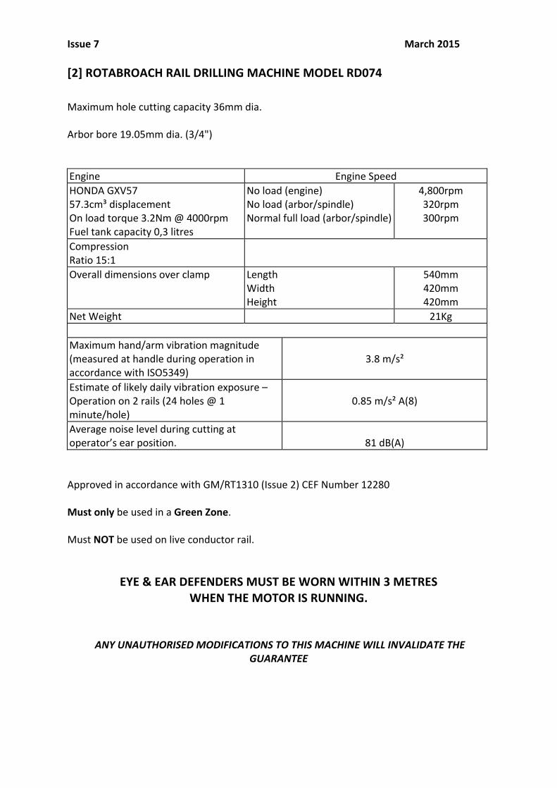
[2] ROTABROACH RAIL DRILLING MACHINE MODEL RD074 Maximum hole cutting capacity 36mm dia. Arbor bore 19.05mm dia. (3/4") Engine Engine Speed HONDA GXV57 57.3cm³ displacement On load torque 3.2Nm @ 4000rpm Fuel tank capacity 0,3 litres
No load (engine) No load (arbor/spindle) Normal full load (arbor/spindle)
4,800rpm 320rpm 300rpm
Compression Ratio 15:1
Overall dimensions over clamp Length Width Height
540mm 420mm 420mm
Net Weight 21Kg
Maximum hand/arm vibration magnitude (measured at handle during operation in accordance with ISO5349)
3.8 m/s²
Estimate of likely daily vibration exposure – Operation on 2 rails (24 holes @ 1 minute/hole)
0.85 m/s² A(8)
Average noise level during cutting at operator’s ear position.
81 dB(A)
Approved in accordance with GM/RT1310 (Issue 2) CEF Number 12280 Must only be used in a Green Zone. Must NOT be used on live conductor rail.
EYE & EAR DEFENDERS MUST BE WORN WITHIN 3 METRES WHEN THE MOTOR IS RUNNING.
ANY UNAUTHORISED MODIFICATIONS TO THIS MACHINE WILL INVALIDATE THE GUARANTEE
Issue 7 March 2015
[3] OPERATIONAL SAFETY PROCEDURES READ BEFORE USING THE MACHINE • ALWAYS WEAR SAFETY GOGGLES AND EAR DEFENDERS WHEN OPERATING THE MACHINE.
• Ensure motor is switched off when changing cutters, working on the machine, or removing swarf. Failure to do so may result in personal injury.
• Always ensure the cutter is securely fastened.
• Remove tie, rings, watches and loose adornments, which might entangle with the rotating machinery. Failure to do so may result in personal injury.
• Should the cutter become fast in the work piece, switch off the motor immediately to prevent personal injury. Do not attempt to free the cutter by starting and stopping the motor. Failure to do so may result in personal injury.
• If the machine is dropped, always thoroughly examine the machine for signs of damage and check that it functions correctly before trying to cut a hole.
• Regularly inspect the machine and check that nuts and screws are tight.
• Before fuelling the tank, read section 5 (fuelling)
• Observe local and national Health & Safety requirements before operating the machine.
• Never leave the machine lying on its side. The motor sump oil may be lost at an inclination greater than 20˚ from the vertical. If this may have happened, check the sump oil level before starting the engine.
• Always wear approved eye and ear protection when the equipment is in operation. Failure to do so may result in personal injury.
• On completion of the cut, a slug will be ejected. DO NOT operate the machine if the ejected slug may cause injury.
[4] ROTABROACH CUTTING FLUID • Rotabroach cutting fluid has been specifically formulated to significantly enhance the performance and life
of the cutting tool, and improve the quality and surface finish of the hole.
• Avialable in 1 litre (RD208) 5 litre (RD229) 25 litre (RD220)
[5] COOLANT INDUCEMENT • Coolant is induced into the system via a pressurised coolant bottle. Connect the coolant bottle to the
machine via the connector and then pressurise the bottle by pumping the coolant bottle’s pump several times. Regulate the flow using the stop tap a quarter turn is usually sufficient.
• Constituent items: Coolant bottle and hose assembly RY2307
Issue 7 March 2015
[6] FUELLING Warning Petrol is an extremely flammable fuel. Use extreme caution when handling petrol or fuel mix. Do not smoke or bring any fire or flame near the fuel. Ensure the fuel mix does not spill on to hot engine. FUELLING INSTRUCTIONS • Fuel your machine in a well-‐ventilated area, outdoors only.
• Avoid direct contact with the skin and avoid inhaling fuel vapour
• Always shut off the engine and allow it to cool before refuelling.
• Before fuelling, clean the filler cap and the area around it to ensure that no dirt falls into the tank.
• Petrol vapour pressure may build up inside the gas tank. In order to reduce the risk of burns or other personal injury from escaping gas vapour and fumes, remove the gas cap carefully so as to allow any pressure build-‐up in the tank to release slowly. Never remove the fuel filler cap whilst the engine is running,
FUEL • It is recommended that you always use unleaded petrol with a minimum octane number of 90
ROZ(USA)/Canada: pump octane min. 87.
• Inferior quality petrol may damage the engine, sealing rings, fuel lines or fuel tank.
[7] MOTOR OPERATING INSTRUCTIONS
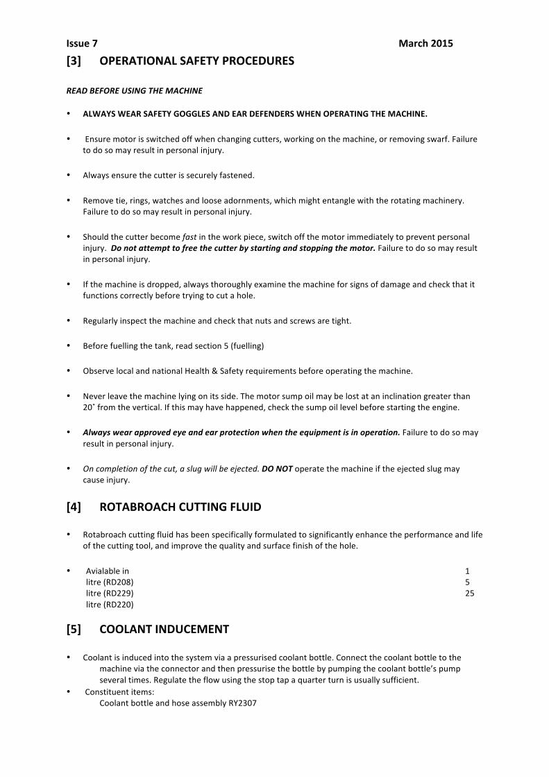
STARTING • Observe safety precautions (see Section 2 – Safety Procedures) • Ensure that the sump oil level is to the correct level. • Ensure the machine is clamped firmly in position on the rail. • Ensure on/off switch (RD4748) is set to 1.

Issue 7 March 2015 • Unscrew petrol tank vent screw. • If the motor is cold, position cold start indicator to 1 o 1. • Rotate the fuel cut off valve to the horizontal position.
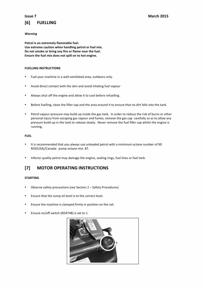
Issue 7 March 2015 • Position the cutter feed handle to the forward position. Repeatedly pull the engine start cord with a quick, progressive movement until the engine starts, then release the cord handle. • When the engine has reached it’s operating temperature, the cold start lever can be moved from the cold
start position. • Moving the cutter feed handle anti-‐clockwise will increase the engine speed and feed the cutter into the
rail.
[8] MACHINE OPERATING INSTRUCTIONS • Keep the inside of the cutter clear of swarf. It restricts the operating depth of the cutter.
• Pressurise the coolant dispenser by pumping the handle until the relief valve extends and then give a further 5 to 10 pumps of the handle.
• With the pressurised cutting fluid dispenser connected to the coolant feed tube, coolant is “metered” out by the pilot and is applied directly to the cutting edge.
• To ensure cutting fluid is being correctly metered, depress the pilot by slowly moving the cutter to touch the rail. Regulate the flow by adjusting the needle valve RD4217.
• As the cutter approaches the rail, the automatic throttle will increase the engine speed to ensure maximum speed before cutting the hole. Once drilling is complete immediately fully retract the cutter, this will return the machine to idle speed. DO NOT ALLOW THE MACHINE TO RUN AT FULL SPEED IF NOT DRILLING.
• When commencing to cut a hole apply light pressure until the cutter is introduced into the work surface. Pressure can then be increased slightly whilst cutting the hole. Excessive pressure is undesirable when using the Rotabroach system, it does not necessarily increase the speed of penetration and it may damage the cutter, greatly reducing its life.
• Cutter breakage is usually caused by insecure clamping.
Issue 7 March 2015
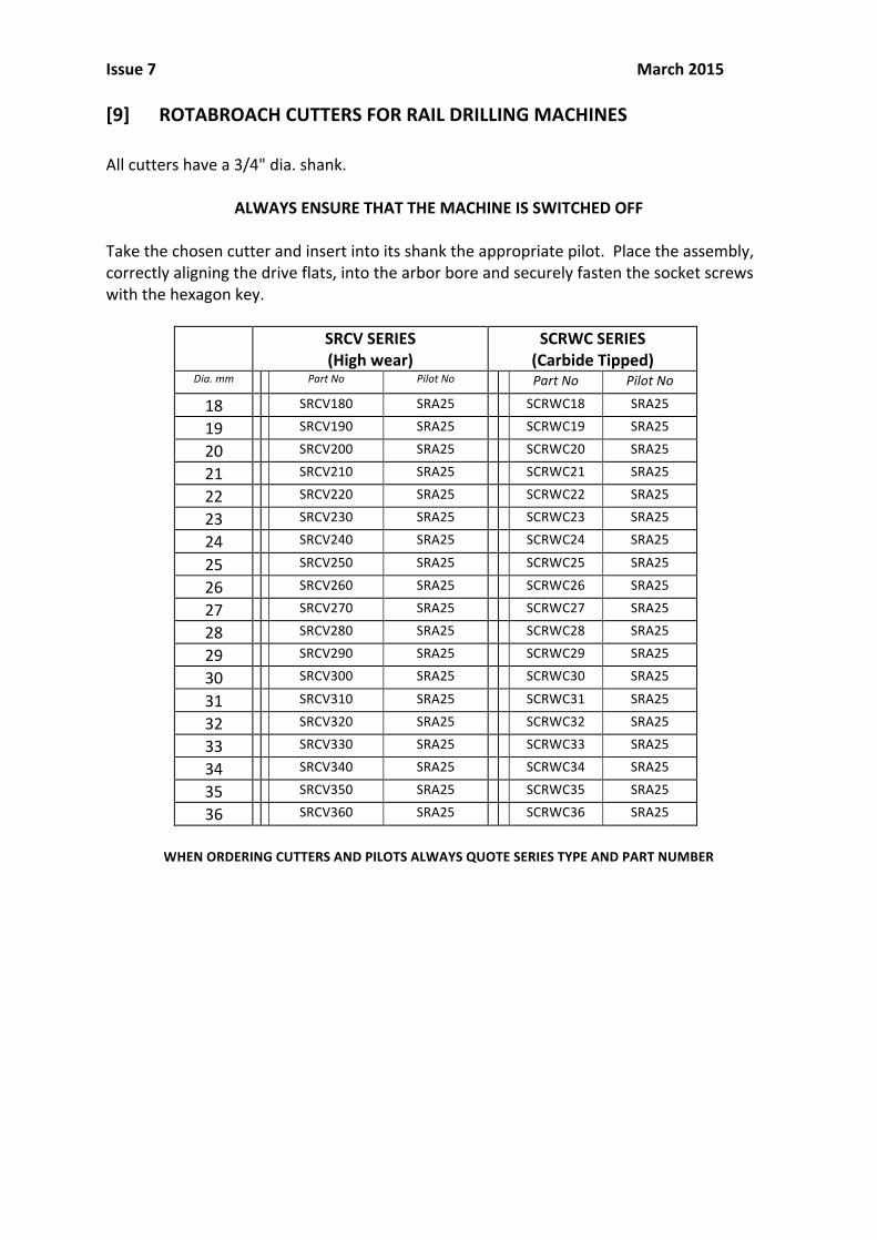
[9] ROTABROACH CUTTERS FOR RAIL DRILLING MACHINES All cutters have a 3/4" dia. shank.
ALWAYS ENSURE THAT THE MACHINE IS SWITCHED OFF Take the chosen cutter and insert into its shank the appropriate pilot. Place the assembly, correctly aligning the drive flats, into the arbor bore and securely fasten the socket screws with the hexagon key.
SRCV SERIES (High wear)
SCRWC SERIES (Carbide Tipped)
Dia. mm Part No Pilot No Part No Pilot No
18 SRCV180 SRA25 SCRWC18 SRA25
19 SRCV190 SRA25 SCRWC19 SRA25 20 SRCV200 SRA25 SCRWC20 SRA25 21 SRCV210 SRA25 SCRWC21 SRA25 22 SRCV220 SRA25 SCRWC22 SRA25 23 SRCV230 SRA25 SCRWC23 SRA25 24 SRCV240 SRA25 SCRWC24 SRA25 25 SRCV250 SRA25 SCRWC25 SRA25 26 SRCV260 SRA25 SCRWC26 SRA25 27 SRCV270 SRA25 SCRWC27 SRA25 28 SRCV280 SRA25 SCRWC28 SRA25 29 SRCV290 SRA25 SCRWC29 SRA25 30 SRCV300 SRA25 SCRWC30 SRA25 31 SRCV310 SRA25 SCRWC31 SRA25 32 SRCV320 SRA25 SCRWC32 SRA25 33 SRCV330 SRA25 SCRWC33 SRA25 34 SRCV340 SRA25 SCRWC34 SRA25 35 SRCV350 SRA25 SCRWC35 SRA25 36 SRCV360 SRA25 SCRWC36 SRA25
WHEN ORDERING CUTTERS AND PILOTS ALWAYS QUOTE SERIES TYPE AND PART NUMBER
Issue 7 March 2015
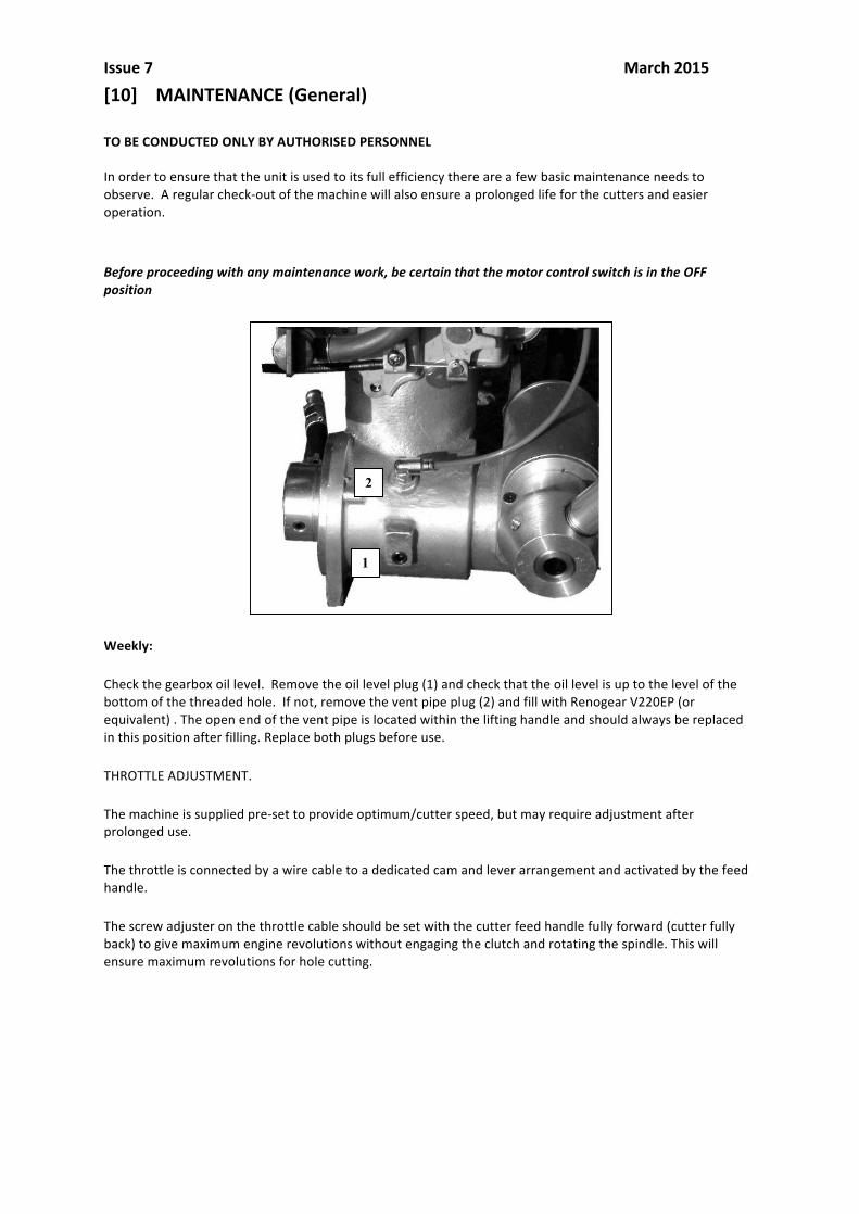
[10] MAINTENANCE (General) TO BE CONDUCTED ONLY BY AUTHORISED PERSONNEL In order to ensure that the unit is used to its full efficiency there are a few basic maintenance needs to observe. A regular check-‐out of the machine will also ensure a prolonged life for the cutters and easier operation. Before proceeding with any maintenance work, be certain that the motor control switch is in the OFF position Weekly:
Check the gearbox oil level. Remove the oil level plug (1) and check that the oil level is up to the level of the bottom of the threaded hole. If not, remove the vent pipe plug (2) and fill with Renogear V220EP (or equivalent) . The open end of the vent pipe is located within the lifting handle and should always be replaced in this position after filling. Replace both plugs before use.
THROTTLE ADJUSTMENT.
The machine is supplied pre-‐set to provide optimum/cutter speed, but may require adjustment after prolonged use.
The throttle is connected by a wire cable to a dedicated cam and lever arrangement and activated by the feed handle.
The screw adjuster on the throttle cable should be set with the cutter feed handle fully forward (cutter fully back) to give maximum engine revolutions without engaging the clutch and rotating the spindle. This will ensure maximum revolutions for hole cutting.
1
2

Issue 6 June 2014
REGULAR SERVICE PERIOD. Perform at indicated month or hour interval, whichever comes first.
Before starting work
First month or 10 hours.
Every 3 months or 25 hours
Ever 6 months or 50 hours
Every 100 hours
Every 2 years or 300 hours
Engine oil Check X X Change X X
Air cleaner Check X
Clean X
Spark plug Clean/adjust X Replace X
Fuel tank filter Clean X
Idle speed Check/adjust X
Valve clearance Check/adjust X Combustion chamber. Clean X
Fuel tubes Check X
Technical specifications
Valve clearance Inlet 0,06-‐0,1mm It is advisable that this service is conducted by an authorised Honda agent, or local specialist distributor. Exhaust 0,09-‐0,31
Idle speed 2500-‐2700 rpm Should be maximum speed possible without cutter spindle rotating.
Spark plug type NGK C5HSB Gap 0,6-‐0,7 (.024”-‐.028”)
Oil type SAE 10W-‐30
Issue 6 June 2014
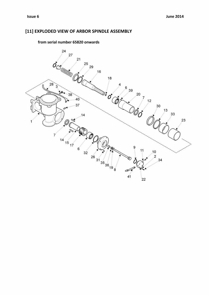
[11] EXPLODED VIEW OF ARBOR SPINDLE ASSEMBLY
from serial number 65820 onwards

Issue 6 June 2014
[11] PARTS LIST FOR ARBOR SPINDLE ASSEMBLY from serial number 65820 onwards
Item Description Part No Quantity Item Description Part No Quantity
1* MAIN HOUSING RD3747 1 22 COOLANT FEED HOUSING RD3792 1 2 M4 SHAKEPROOF WASHER RD4069 4 23* REAR BRONZE BEARING RD3719 1 3 M8 DOG POINT SOCKET SCREW RD4719 1 24 CIRCLIP RD4056 1 4 CIRCLIP RM22876 1 25 FEED TUBE WEAR CAP RD3714 1 6 COMBINED NEEDLE THRUST RACE RD4700 2 26 HOUSING REAR ENDCAP RD3745 1 7 BEARING RD4701 2 27 BUTTON RA354 1 8 COOLANT FEED TUBE RD3793 1 28 VENT PIPE RD3770 1 9 ‘O’ RING RD4702 1 29 OILSEAL RD4704 1 10 COOLANT TUBE CLAMP SCREW RD3713 1 30* OILSEAL PROTECTION RING RD3718 1 11 ‘O’ RING RD4703 1 31 M4 C/SUNK SKT HD SCREW RD4721 4 12 CIRCLIP RD4713 1 32 ‘O’ RING RD4736 1 13 OIL SEAL RD4712 1 33* FRONT BRONZE BEARING RD4711 1 14 FINAL DRIVE KEY RD4705 2 34 M4 SCKT HEAD CAP SCREW RD4728 4 15 FINAL DRIVE SPINDLE RD3707 1 35 M8 x 15 CAPSCREW RD4184 1 16 ARBOR/SPINDLE RD3704 1 36 M8 WASHER RD4078 1 17 GEAR SET RD4742 1 37 1/8” BSPT PLUG RD4745 1 18 ‘O’ RING RD4706 1 38 M8 HEX NUT RD4192 1 19 ‘O’ RING RD47174 1 39 ROLL PIN RD4740 1 20 FEED TUBE RD3701 1 40 1/8” BSP ELBOW RD4754 1 21 SPRING RA355 1 41 FLEXIBLE HOSE ASSEMBLY RD2709 1
* SUPPLIED AS ASSEMBLY RD2708
Issue 6 June 2014
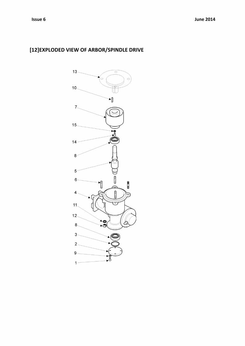
[12]EXPLODED VIEW OF ARBOR/SPINDLE DRIVE

Issue 6 June 2014
[12] PARTS LIST FOR ARBOR/SPINDLE DRIVE
Item Description Part No Quantity
1 M4 SHCS RD4414 4 2 SHAFT COVER RD3746 1 3 O’RING RD4737 1 4 MAIN HOUSING RD3747 1 5 GEAR SET RD4742 1 6 M6 STUD RD4340 4 7 CLUTCH ASSEMBLY RD4779 1 8 BEARING RD4082 2 9 M4 SHAKEPROOF WASHER RD4069 4 10 KEY RD3771 1 11 M6 WASHER RD4207 4 12 M6 NYLOC NUT RD4223 4 13 HONDA PETROL MOTOR RD4778 1 14 M6 SHCS RD4156 1 15 M6 WASHER RD4095 1
Issue 6 June 2014
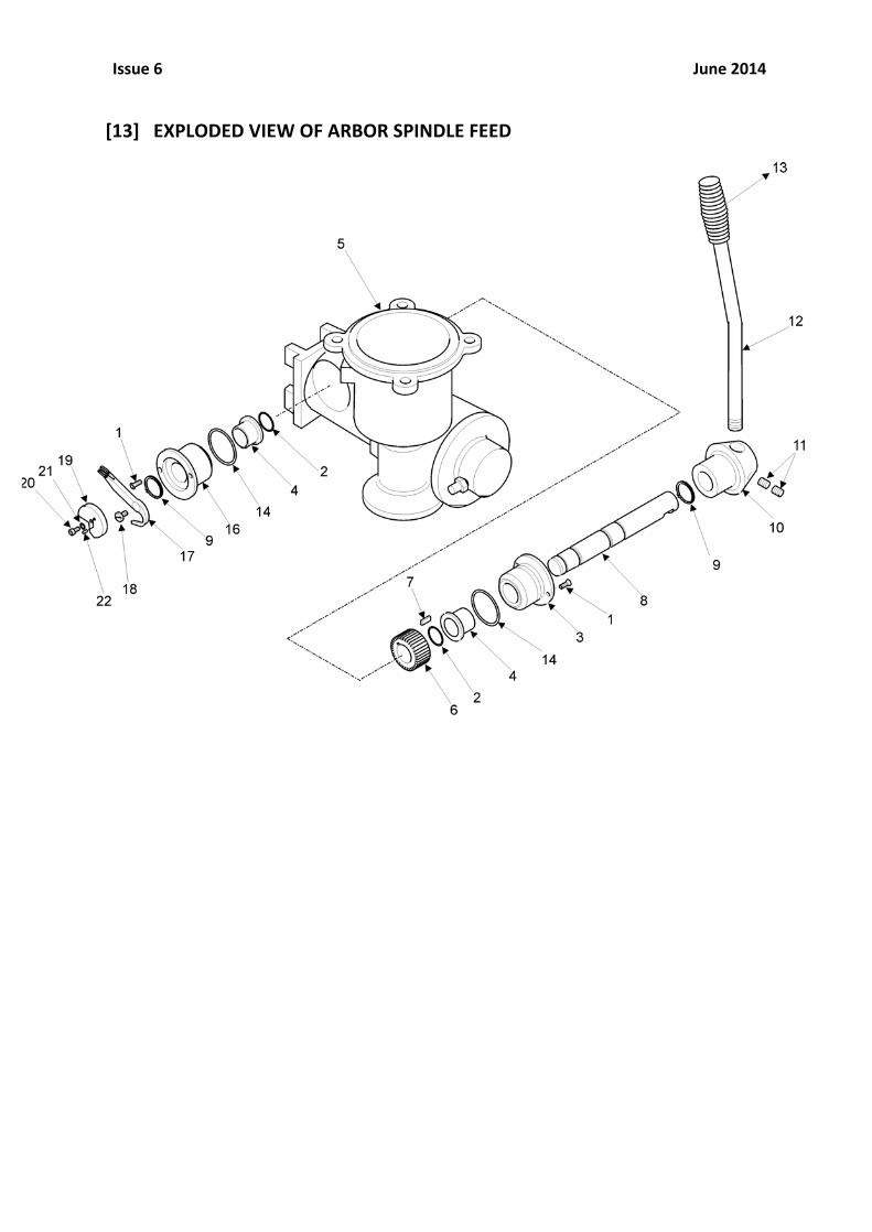
[13] EXPLODED VIEW OF ARBOR SPINDLE FEED

Issue 6 June 2014
[13] PARTS LIST FOR ARBOR/SPINDLE FEED
Item Description Part No Quantity
1 M4 CSINK SET SCREW RD4721 3 2 O’ RING RD4726 2 3 CAPSTAN SPINDLE HOUSING RD3712 1 4 FLANGED OILITE BUSH RD4724 2 5 MAIN HOUSING RD3747 1 6 FEED GEAR RD3705 1 7 FEED GEAR KEY RD4708 1 8 CAPSTAN SPINDLE RD3758 1 9 CIRCLIP RD4730 2 10 CAPSTAN HUB RD3725 1 11 M8 SOCKET SCREW RD4066 2 12 CAPSTAN ARM RD3759 1 13 HAND GRIP RD4752 1 14 O’ RING RD4727 2 16 CAPSTAN SPINDLE HOUSING RD3757 1 17 THROTTLE LINK RD3755 1 18 THROTTLE LINK PIVOT RD3756 1 19 THROTTLE CAM RD3754 1 21 SHCS M5 RD4325 1 22 3 DIA ROLL PIN RD4744 1
Issue 6 June 2014
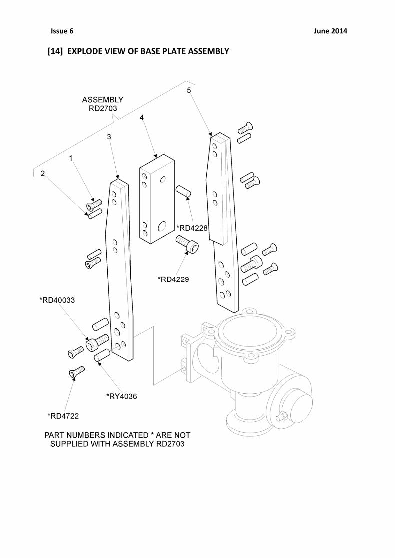
[14] EXPLODE VIEW OF BASE PLATE ASSEMBLY

Issue 6 June 2014
[14] PARTS LIST FOR BASE PLATE ASSEMBLY
Item Description Part No Quantity
1 M6 C/SNK SET SCREW RD4722 4 2 6MM DOWEL RD4242 4 3 SIDE PLATE (LH) RD3731 1 4 CLAMP BLOCK RD3715 1 5 SIDE PLATE (RH) RD3732 1
Issue 6 June 2014
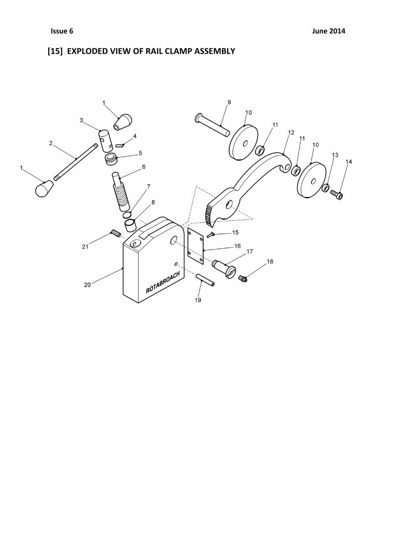
[15] EXPLODED VIEW OF RAIL CLAMP ASSEMBLY

Issue 6 June 2014
[15] PARTS LIST FOR RAIL CLAMP ASSEMBLY
Item No
Description Part No Quantity
1 CAPSTAN KNOB RY4060 2 2 CAPSTAN SPINDLE RY4061 1 3 CAPSTAN RY4062 1 4 PIN RY4063 1 5 COLLAR RY4064 1 6 WORM RY4065 1 7 THRUST WASHER RY4066 1 8 BEARING BUSH RY4067 1 9 ROLLER PIN RY4068 1 10 ROLLER RY4069 2 11 DISTANCE PIECE RY4070 2 12 CLAMP ARM RY4071 1 13 COLLAR RY4072 1 14 SCREW RY4325 1 15 RIVET RY4074 4 16 GUARD PLATE RY4075 1 17 PIVOT PIN RY4076 1 18 LUBRICATION NIPPLE RY4077 1 19 ROLL PIN RY4078 1 20 CLAMP BODY RY4079 1 21 LOCK SCREW RY4368 1
Issue 6 June 2014
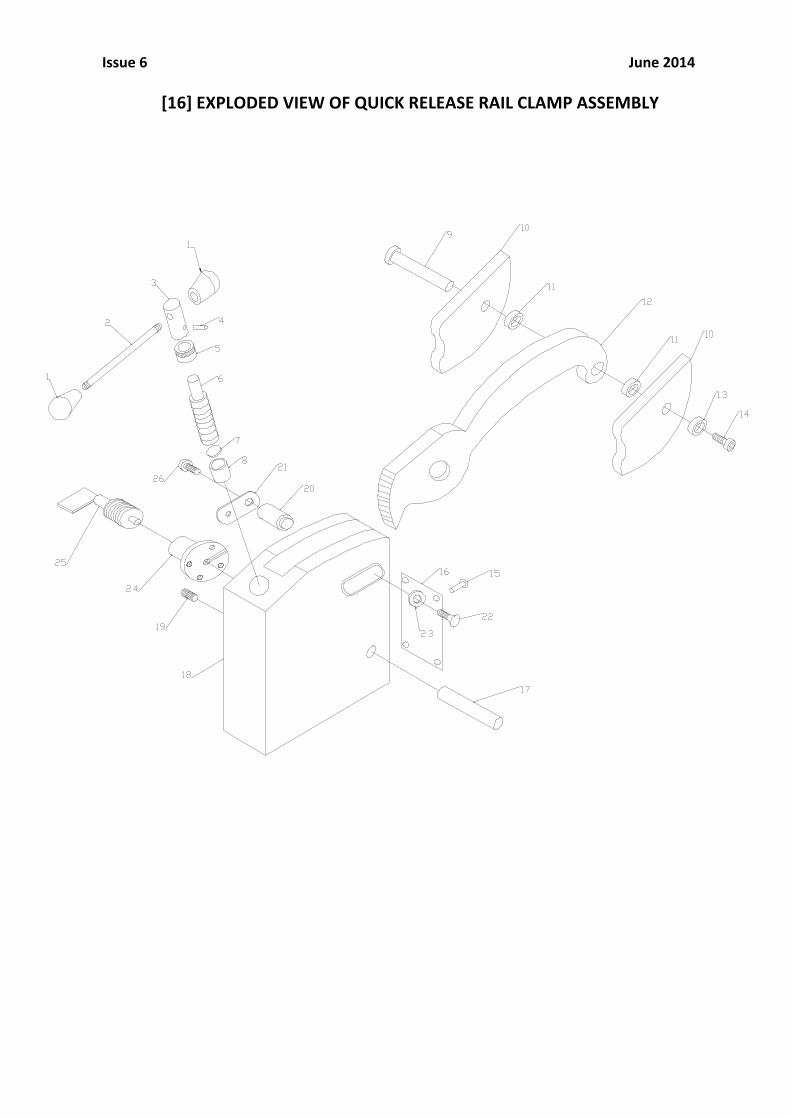
[16] EXPLODED VIEW OF QUICK RELEASE RAIL CLAMP ASSEMBLY

Issue 6 June 2014
[16] PARTS LIST FOR QUICK RELEASE RAIL CLAMP ASSEMBLY
Item No
Description Part No Quantity
1 CAPSTAN KNOB RY4060 2 2 CAPSTAN SPINDLE RY4061 1 3 CAPSTAN RY4062 1 4 PIN RY4063 1 5 COLLAR RY4064 1 6 WORM RY4065 1 7 THRUST WASHER RY4066 1 8 BEARING BUSH RY4067 1 9 ROLLER PIN RY4068 1 10 ROLLER RY3749 2 11 DISTANCE PIECE RY4070 2 12 CLAMP ARM RY4071 1 13 COLLAR RY4072 1 14 SCREW RY4325 1 15 RIVET RY4074 4 16 GUARD PLATE RY4075 1 17 ROLL PIN RY4078 1 18 CLAMP BODY RY33125 1 19 LOCK SCREW RY4368 1 20 CONNECTING ROD RY33126 1 21 SLIDE BAR RY33127 1 22 COUNTERSUNK M5 RD4347 1 23 WASHER RY33138 1 24 CLAMP CONNECTOR RY33128 1 25 BALL PLUNGER RY4095 1 26 M5 X 16 SOCKETHEAD RD4325 1

Issue 6 June 2014
Notes:

Issue 6 June 2014
Notes:

Issue 6 June 2014
Notes:
Issue 6 June 2014
[13] WARRANTY STATEMENT
Rotabroach® warrants its machines to be free from faulty materials, or workmanship under normal use for a period of 12 months from initial date of purchase and 90 days for all other parts (excluding cutters), provided that the warranty registration card (or online registration) has been completed and returned to Rotabroach®, or its designated distributor within a period of (30) days from the purchase date, failure to do so will void the warranty. If the stated is adhered to Rotabroach® will repair or replace (at its option) without charge any faulty items returned. This Warranty does not cover: 1. Components that are subject to natural wear and tear caused by the use in accordance with the operators instructions 2. Defects in the tool caused by non-‐compliance with the operating instructions, improper use, abnormal environment conditions, inappropriate operating conditions overload or
insufficient servicing or maintenance. 3. Defects caused by using accessories, components or spare parts other than original Rotabroach® parts. 4. Tools to which changes or additions have been made. 5. Electrical components are subject to manufacturer’s warranty.
Your online registration can be submitted on www.rotabroach.co.uk The warranty claim must be lodged within the warranty period. This requires the submission or sending of the complete tool in question with the original sales receipt which must indicate the purchase date of the product. A complaint form must also be submitted prior to the return. This can be found online at www.rotabroach.co.uk Failure to complete this form will result in the delay of your claim. All goods returned defective must be returned pre-‐paid to Rotabroach®, in no event shall Rotabroach® be liable for subsequent direct, or indirect loss or damage.
THIS WARRANTY IS IN LIEU OF ANY OTHER WARRANTY, (EXPRESSED OR IMPLIED) INCLUDING ANY WARRANTY OF MECHANTABLITY OR FITNESS FOR A PARTICULAR PURPOSE. ROTABROACH® RESERVE THE RIGHT TO MAKE IMPROVEMENTS AND MODIFICATIONS TO DESIGN WITHOUT PRIOR NOTICE
Known and Trusted Worldwide for Quality, Performance and Reliability