Embed Size (px)
Citation preview

SERVICE MANUAL
(Machine code: C229)

1
IMPORTANT SAFETY NOTICES
PREVENTION OF PHYSICAL INJURY
1. Before disassembling or assembling parts of the printer and peripherals, makesure that the power cord is unplugged.
2. The wall outlet should be near the printer and easily accessible.
3. If any adjustment or operation check has to be made with exterior covers off oropen while the main switch is turned on, keep hands away from electrified ormechanically driven components.
HEALTH SAFETY CONDITIONS
1. If you get ink in your eyes by accident, try to remove it with eye drops or flushwith water as first aid. If unsuccessful, get medical attention.
2. If you ingest ink by accident, induce vomiting by sticking a finger down yourthroat or by giving soapy or strong salty water to drink.
OBSERVANCE OF ELECTRICAL SAFETY STANDARDS
1. The printer and its peripherals must be installed and maintained by a customerservice representative who has completed the training course on those models.
ICAUTION
The RAM has a lithium battery which can explode if handled incorrectly.Replace only with the same type of RAM. Do not recharge or burn thisbattery. Used RAM's must be handled in accordance with local regulations.
IATTENTION
La carte RAM comporte une pile au lithium qui présente un risqued'explosion en cas de mauvaise manipulation. Remplacer la pileuniquement par une carte RAM identique. Ne pas recharger ni brûler cettepile. Les cartes RAM usagées doivent être éliminées conformément auxréglementations locales.

2
SAFETY AND ECOLOGICAL NOTES FOR DISPOSAL
1. Dispose of replaced parts in accordance with local regulations.
2. Used ink and masters should be disposed of in an environmentally safemanner and in accordance with local regulations.
3. When keeping used lithium batteries (from the main processing units) in orderto dispose of them later, do not store more than 100 batteries (from the mainprocessing units) per sealed box. Storing larger numbers or not sealing themapart may lead to chemical reactions and heat build-up.

1 July, 1998 SPECIFICATIONS
1-1
Ove
rall
Info
rmat
ion1. OVERALL INFORMATION
1.1 SPECIFICATIONS
Configuration: Desktop
Master Processing: Digital with 400 dpi thermal head
Scanning (Pixel Density): 400 dpi CCD
Printing Process: Fully automatic stencil system, with one drum andpressure cylinder system
Original Type: Sheet/Book
In Platen Mode: Document size:Maximum 304.8 x 432 mm [12.0" x 17.0"]
Thickness: Less than 30 mmWeight: Less than 10 kg
In ADF Mode: Document size:Maximum 297 x 864 mm [11.6" x 33.8"]Minimum 105 x 128 mm [4.2" x 5.1"]
Document weight:52.3 - 104.7 g/m2 [14 - 28 lb]
ADF capacity:30 sheets (using 20 lb or 80 g/m2 paper)
Reproduction Ratios: Inch versions Others
Full Size: 100% 100%
Reduction: 65% 71% 74% 82% 77% 87% 93% 93%
Enlargement: 121% 115%129% 122%155% 141%
Zoom: 50 - 200% (by 1%) in Platen mode50 - 155% (by 1%) in ADF mode
Directional Magnification:50 - 200% (by 1%)
Image Modes: Letter, Photo, Letter/Photo, Pencil, Tint

SPECIFICATIONS 1 July, 1998
1-2
Printing Area:(At 20 °C/ 65 % RH)
Metric size version models:290 mm x 409 mm
Inch size version models:290 mm x 419 mm [11.4" x 16.4"]
With optional A4 drum:290 mm x 204 mm [11.4" x 8.0"]
Edge Margins: Leading edge:10 mm (At the "0" position of Image Shift mode)
Trailing edge:2 mm
Print Paper Size: Minimum: 70 mm x 148 mm [2.8" x 5.9"]Maximum: 325 mm x 447 mm [12.7" x 17.6"]
Print Paper Weight: 47.1 g/m2 to 209.3 g/m2 [12.5 lb to 55.6 lb]
Printing Speed: 60, 75, 90, 105, 120 sheets/minute (5 steps)
Master Process Time: Platen mode:Less than 15.5 seconds (A3 paper)Less than 12 seconds (A4 paper)
ADF mode:Less than 19.5 seconds (A3 paper)Less than 16 seconds (A4 paper)
Master Eject Box Capacity: 60 masters / A3 size (Normal conditions)
Side Registration AdjustableRange:
± 10 mm
Vertical Registration AdjustableRange:
Inch size version models:± 10 mm
Metric size version models:± 15 mm
Paper Feed Table Capacity: 1000 sheets (80 g/m2 / 20 lb)
Paper Delivery Table Capacity: 1000 sheets (80 g/m2 / 20 lb)
Power Source: 110/120 V, 50/60 Hz: 2.7 A220 - 240 V, 50/60 Hz: 1.5 A
Maximum Power Consumption: 110/120 V version: 285 W220 - 240 V version: 280 W

1 July, 1998 SPECIFICATIONS
1-3
Ove
rall
Info
rmat
ion
Noise Emission:(At operation position)
At 60 rpm printing speed: 57 dBAt 90 rpm printing speed: 60 dBAt 120 rpm printing speed: 64 dB
Weight: 94 kg [207 lb]101 kg [222.7 lb] with ADF
Dimensions:(Width x Depth x Height)
Trays closed: 625 mm x 650 mm x 574 mmWith ADF:625 mm x 650 mm x 684 mm
Trays open: 1405 mm x 650 mm x 574 mmWith ADF:1405 mm x 650 mm x 684 mm
Master Type: Thermal master roll type:420 mm width, 110 m / roll
Yield:200 masters/roll (at A3 size)
Max run length per master:2,000 prints
Master Storage Conditions: Temperature:-10 °C to 40 °C
Humidity:10% to 95% RH
Recommended maximum storage period:One year after production date
* Avoid locations exposed to direct sunlight.
Ink Type 1000 ml cartridge type
Available colors:Black, Red, Blue, Green, Brown
Ink Storage Conditions: Temperature:-5 °C to 40 °C(Optimum conditions: 15 °C to 25 °C)
Humidity:10% to 95% RH(Optimum conditions: 20% to 70% RH)
Recommended maximum storage period:One year after production date
* Avoid locations exposed to direct sunlight.

SPECIFICATIONS 1 July, 1998
1-4
Available Options • A3 Drum• A4 Drum• Document Feeder• Key Counter• Memory Board (Editing Function)• PC Controller• Interface Board (Standard for the U.S.A and
European versions)

1 July, 1998 GUIDE TO COMPONENTS AND THEIR FUNCTION
1-5
Ove
rall
Info
rmat
ion1.2 GUIDE TO COMPONENTS AND THEIR FUNCTION
1.2.1 MACHINE EXTERIOR
1. Front Door Open for access to the inside of themachine.
2. Flip-up Cover Open to access the Image Density key andso on.
3. Operation Panel Operator controls and indicators arelocated here.
4. Master Feed Unit Open the master feed unit when installingthe master.
5. Paper Feed Tray Down key Press to lower the paper feed tray.
6. Paper Feed Side/EndPlates
Use to prevent paper skew.
7. Paper Feed Tray Set paper on this tray for printing.
8. Paper Feed Side/End PlateKnob
Use to move the side/end plates.
C229V500.WMF

MACHINE INTERIOR 1 July, 1998
1-6
1.3 MACHINE INTERIOR
C229V501.WMF

1 July, 1998 MACHINE INTERIOR
1-7
Ove
rall
Info
rmat
ion
1. Main Switch Use to turn the power on or off.
2. Paper Alignment WingKnobs
Use to lift or lower the paper alignmentwings.
3. Paper Alignment Wings Lift or lower the wings depending on thepaper type you use.
4. Paper Delivery End Plate This plate aligns the leading edge of prints.
5. Paper Delivery End PlateKnob
Use to move the end plate.
6. Paper Delivery Tray Completed prints are delivered here.
7. Paper Delivery Side Plates These plates align the prints on the paperdelivery tray.
8. Paper Delivery Side PlateKnobs
Use to move the side plates.
9. Master Eject Unit FrontHandle E1
Use to pull out the master eject unit.
10. Ink Holder Set the ink cartridge in this holder.
11. Drum Unit Lock Lever B1 Lower to unlock and pull out the drum unit.
12. Drum Unit The master is wrapped around this unit.
13. Exposure Glass (ContactGlass)
Position originals here face down forprinting.
14. Platen Cover Lower this cover over an original beforeprinting.
15. Trailing Edge Guides Swing out these guides when you use A4,81/2" x 11" sideways, or B5 lengthwisepaper.

MACHINE INTERIOR 1 July, 1998
1-8
1.3.1 OPERATION PANEL
1. Quality Start key
2. Security key
3. Skip Feed key
4. User Tools keyPress to change the defaultsettings and conditions to meetyour requirements.
5. Stamp key
6. Make-up key
7. Overlay key
8. Edge Erase key
9. Image Density keyPress to make prints darker orlighter.
10. Tint key
11. Economy Mode key
12. On Line key
13. Job Separator key
14. Combine keyPress to combine originals ontoone print.
15. Class keyPress to select All Class, AutoClass, Manual Class, or Classmode.
16. Speed keys
17. Scroll keysPress to shift the image forward,backward, right, or left.
C229V502.WMF

1 July, 1998 MACHINE INTERIOR
1-9
Ove
rall
Info
rmat
ion
18. Program keyPress to input or recall userprograms.
19. Number keys
20. Clear/Stop keyWhile printing, press to stop themachine.
21. Enter keyUse to enter data in selectedmodes.
22. Clear Modes keyPress to clear the previouslyentered job settings.
23. Start keyPress to make a master.
24. Auto Cycle keyUse to process the master andmake prints at one stroke.
25. Proof keyPress to make a proof print.
26. Print keyPress to start printing.
C229V502.WMF

MACHINE INTERIOR 1 July, 1998
1-10
1.3.2 INDICATORS
1. Special Feature indicator
This indicator is lit when youpress keys under the flip-upcover.
5. Color Drum indicator
This indicator is lit when the colordrum unit is installed.
2. Monitors
The monitors light up when anon-standard condition occurswithin the machine.
6. Counter
Displays the number of printsentered. While printing, it showsthe number of prints remaining.
3. A3/11" x 17" Drum indicator
This indicator is lit when the A3,11" x 17" drum unit is installed.
7. Panel Display
4. A4/81/2" x 11" Drum indicator
This indicator is lit when the A4,81/2" x 11" drum unit is installed.
C229V503.WMF

1 July, 1998 PRINTING PROCESS OVERVIEW
1-11
Ove
rall
Info
rmat
ion1.4 PRINTING PROCESS OVERVIEW
1. Master Ejecting: Ejects the used master wrapped around the druminto the master eject box.
2. Scanning: Scans the original image with the CCD through themirrors and the lens.
3. Master Feeding: Converts the image signal read by the CCD intodigital signals and sends them to the thermal head todevelop the image on the master. The master thenwraps around the drum.
4. Paper Feeding: Sends paper to the drum section.
5. Printing: Presses the paper fed from the paper feed sectionagainst the drum. This transfers ink to the paperthrough the drum screen and the master.
6. Paper Delivering: Peels off the printed paper with the exit pawls and airknife, and ejects the paper onto the paper deliverytable.
NOTE: Some parts of the master eject, scanning, and master feeding processesare carried out at the same time. Paper feeding also starts before themaster feeding process has finished.
C229V008.WMF
1
2 3
4
5
6

MECHANICAL COMPONENT LAYOUT 1 July, 1998
1-12
1.5 MECHANICAL COMPONENT LAYOUT
1. Master Feed Control Roller2. Lens3. CCD4. SBU5. Tension Roller6. Platen Roller7. Master Set Roller8. Master Roll9. Thermal Head10. Master Buffer Duct11. Paper Table12. Paper Feed Roller13. Paper Separation Roller14. Registration Rollers15. Doctor Roller16. Pressure Cylinder17. Ink Roller
18. Idling Roller19. Transport Belts20. Job Separator Unit21. Paper Delivery Table22. Master Eject Rollers23. Master Eject Box24. Master Pick-up Roller25. 2nd Scanner26. 1st Scanner27. DF Exposure Glass28. 1st Transport Roller29. 2nd Transport Roller30. Original Feed Belt31. Separation Roller32. Pick-up Roller33. Original Exit Roller
C229V008.WMF
1 2
45
3
6
7
8
9
10
11
121314151617181920
21
22
23
24
25
26
2829
30 31 32 33
27

1 July, 1998 ELECTRICAL COMPONENT LAYOUT
1-13
Ove
rall
Info
rmat
ion1.6 ELECTRICAL COMPONENT LAYOUT
1.6.1 PRINTED CIRCUIT BOARD LAYOUT
C229V007.WMF
1
2
3
45
6
7
10
11
9
8

ELECTRICAL COMPONENT LAYOUT 1 July, 1998
1-14
1.6.2 SCANNER SECTION
1.6.3 PAPER FEED SECTION
C229V001.WMF
C229V002.WMF
20
21
22
23
24
25
26
27
1918
34
33
32
31
3029 28
1112
1314
15
16
17

1 July, 1998 ELECTRICAL COMPONENT LAYOUT
1-15
Ove
rall
Info
rmat
ion1.6.4 MASTER EJECT, PRESSURE CYLINDER, AND OTHER
SECTIONS
C229V003.WMF
3837 39 4041
42
43
44
46
48
45
49
5051
525354
55
56
57
58
59
35
36
47

ELECTRICAL COMPONENT LAYOUT 1 July, 1998
1-16
1.6.5 PAPER DELIVERY SECTION
1.6.6 MASTER MAKING UNIT
C229V010.WMF
C229V005.WMF
60
61
62
63
64
65
66
67
6869
72
73
74
7170
75 7778
80
81
79
82
83
84
85
86
76

1 July, 1998 ELECTRICAL COMPONENT LAYOUT
1-17
Ove
rall
Info
rmat
ion
1.6.7 DRUM UNIT
C229V006.WMF
8887
89
90
91
92
93
94
95
97 96

ELECTRICAL COMPONENT LAYOUT 1 July, 1998
1-18
1.6.8 TABLES OF ELECTRICAL COMPONENTS
BoardsIndex No. Name Function
1 Operation Panel Board Controls the operation panel.2 Lamp Stabilizer Provides dc power for the xenon lamp.3 Job Separator Board Controls the job separator.4 Main Motor Control
BoardControls the main motor.
5 Power Supply Unit(PSU)
Provides dc power to the system.
6 Main Processing Unit(MPU)
Controls all machine functions both directly andthrough other boards.
7 I/O Board Controls the mechanical components.8 Memory Board Enables the image editing function and data
printout via SP mode. This is an option.9 Interface Board Enables the connection with the PC controller.
This is an option for the China and Ricoh Asiaversions.
10 Thermal Head PowerSupply Board
Provides dc power to the thermal head.
11 Sensor Board Unit(SBU)
Contains the CCD, and outputs a video signal tothe MPU.
19 Feed PressureDetection Board
Sends data about the paper feed pressure to theCPU.
26 Paper Width DetectionBoard
Sends data about the paper width on the papertable to the CPU.
51 Separation PressureDetection Board
Sends data about the paper separation pressureto the CPU.
97 Ink Detection Board Checks if there is ink in the drum.
SolenoidsIndex No. Name Function
54 Printing PressureRelease Solenoid
There are two solenoids: one at the front andone at the rear. They pull the release arms toapply the printing pressure against the drum.
86 Duct Entrance Solenoid Opens or closes the plate at the entrance of themaster buffer duct.
SwitchesIndex No. Name Function
33 Paper Table LoweringSwitch
Lowers the paper table.
35 Main Switch Turns the power on or off.56 Cover Safety Switches Checks if the front door is set correctly.

1 July, 1998 ELECTRICAL COMPONENT LAYOUT
1-19
Ove
rall
Info
rmat
ion
MotorsIndex No. Name Function
17 Scanner Drive Motor Drives the scanner.21 Feed Pressure Motor Drives the paper feed pressure adjustment
mechanism.22 Registration Motor Feeds the paper to align it with the image on the
master on the drum.23 Paper Feed Motor Feeds the paper from the paper table.25 Paper Table Motor Raises and lowers the paper table.36 Pressure Plate Motor Raises and lowers the pressure plate in the
master eject box.37 Master Eject Motor Sends used masters into the master eject box.40 Image Shift Motor Makes a phase difference between the positions
of the drum and pressure cylinder for theup/down image shifting mode.
47 Clamper Motor Opens or closes the drum master clamper.50 Separation Pressure
MotorDrives the paper separation pressureadjustment mechanism.
58 Main Motor Drives the drum, pressure cylinder, and paperdelivery unit components.
60 Transport Vacuum Fan Provides suction so that paper is held firmly onthe transport belts.
61 Air Knife Fan Provides air to separate the paper leading edgefrom the drum.
63 Wing Guide Motor Changes the position of the paper wing guidesin the paper delivery unit.
66 Pressure Cam ShiftMotor
Switches the cams for the small master and fullsize master to apply the appropriate printingpressure.
69 Slider Lift Motor Moves the sliding arm in the job separator unitup or down.
72 Job Separator Motor Drives the sliding arm in the job separator unit.78 Cutter Motor Cuts the master after completing the master
making.82 Platen Release Motor Applies or releases the pressure between the
platen roller and the thermal head.83 Master Feed Motor Feeds the master to the drum.84 Master Vacuum Fan Provides suction to guide the master into the
buffer duct.87 Ink Pump Motor Drives the ink pump to supply ink.89 Idling Roller Motor Presses or releases the idling roller against the
drum screen.91 Drum Shift Motor Slides the drum screen position to the front or
rear for the side-to-side image shifting mode.

ELECTRICAL COMPONENT LAYOUT 1 July, 1998
1-20
SensorsIndex No. Name Function
12 Original Width Sensor Detects the width of the original on the exposureglass.
13 Scanner HP Sensor Detects when the scanner is at home position.15 Platen Cover Sensor Detects if the platen cover is open or closed.16 Original Length Sensor Detects the length of the original on the
exposure glass.18 Master Making Unit Set
SensorChecks if the master making unit is set.
24 Paper Table LowerLimit Sensor
Detects when the paper table is at its lower limitposition.
27 Paper Length Sensor Detects when long paper is on the paper table.28 Paper Table Set Sensor Detects if the paper table is closed.29 Paper End Sensor Detects if paper is present on the paper table.30 Paper Height Sensor Detects if the top of the paper stack on the
paper table is at the paper feed height.31 Paper Registration
SensorDetects paper approaching the registrationroller.
32 Paper Feed TimingSensor
Detects paper approaching the paper clamper inthe pressure cylinder.
38 Pressure Plate HPSensor
Detects when the pressure plate is at the homeposition.
39 Pressure Plate LimitPosition Sensor
Detects when the pressure plate is at the lowestposition.
41 Image Shift HP Sensor Detects if the pressure cylinder is at the homeposition. (The up/down image shift is 0.)
42 Image Position Encoder Sends the image position data to the CPU fordisplay on the operation panel.
43 2nd Drum PositionSensor
Checks the drum position.
44 1st Drum PositionSensor
Checks the drum position.
45 Clamper Close PositionSensor
Detects when the clamper is in the closedposition.
46 Clamper Open PositionSensor
Detects when the clamper is in the openposition.
48 2nd Drum MasterSensor
Detects if there is a master on the drum, todetect master clamping errors.
49 1st Drum MasterSensor
Detects if there is a master on the drum whenthe Start key is pressed.
52 Feed Encoder Detects fluctuations in the pressure cylinderrotation.
53 Feed Start Sensor Checks the pressure cylinder position for thepaper feed start timing.
55 Lower Wrapping JamSensor
Detects paper wrapping jams on the pressurecylinder.
58 Master Eject Sensor Detects master eject misfeeds.59 Eject Box Set Sensor Checks if the master eject box is installed.

1 July, 1998 ELECTRICAL COMPONENT LAYOUT
1-21
Ove
rall
Info
rmat
ion
Index No. Name Function62 Paper Exit Sensor Detects paper misfeeds at the exit.64 A3 Cam Sensor Detects when the A3 printing pressure cam is
used.65 A4 Cam Sensor Detects when the A4 printing pressure cam is
used.67 Slider Position Sensor Detects when the job separator slider is fully
moved toward the paper on the delivery table.68 Slider HP Sensor Detects when the job separator slider is at the
home position.70 Paper Sensor Detects when the job separator slider touches
the paper on the delivery table.71 Slider Upper Limit
SensorDetects when the job separator slider is at theuppermost position.
73 Wing Upper PositionSensor
Detects when the paper wing guides are in theupper position.
74 Wing Lower PositionSensor
Detects when the paper wing guides are in thelower position.
75 Master Edge Sensor Detects the leading edge of the master when anew master roll is installed.
77 Cutter HP Sensor Detects when the cutter is at the home position.80 Master Set Sensor Detects whether a master roll is present.81 Platen Release Sensor Detects when the platen pressure is applied
against the thermal head.85 Master End Sensor Detects when the master runs out.88 Drum Shift HP Sensor Detects when the drum screen is at the home
position. (The side-to-side image shift is 0.)90 Drum Shift Sensor Sends the image position data to the CPU for
display on the operation panel.92 Ink Pump Sensor Monitors the operation of the ink pump to count
how many cycles it has moved.95 Ink Cartridge Set
SensorDetects if the ink cartridge is in place.
96 Idling Roller HP Sensor Detects when the idling roller is at the homeposition.
OthersIndex No. Name Function
14 Xenon Lamp Applies light to the original for exposure.20 Interface Connector Connects the machine to the PC controller.34 Print and Master
CountersKeeps track of the total number of prints andmasters.
76 Master Feed Clutch Controls the master feed control roller operationto feed the master.
79 Thermal Head Burns the image of the original onto the master.93 Thermistor Detects the temperature inside the drum to
adjust various process.94 Ink Detecting Pin Detects if ink is present in the drum.

DRIVE LAYOUT 1 July, 1998
1-22
1.7 DRIVE LAYOUT
1.7.1 OVERVIEW
1. Clamper Opening Arm SectorGear (for the master eject position)
2. Master Pick-up Roller Sector Gear
3. Master Eject Motor
4. Image Shift Motor
5. Pressure Plate Motor
6. Exit Pawl Drive Cam Gear
7. Paper Delivery Unit DriveGear/Pulley
8. Main Motor
9. Pressure Cylinder Drive Gear(Including the Scissors Gear)
10. Registration Roller Lifting Cam DriveGear
11. Registration Motor
12. Paper Feed Motor
13. Paper Table Motor
14. Clamper Motor
15. Drum Guide
16. Master Feed Motor
17. Master Feed Clutch
C229V504.WMF
2117
16
15
14
12 11 10 9
8
7
6
5
4
3
13
1 July, 1998 DRIVE LAYOUT
1-23
Ove
rall
Info
rmat
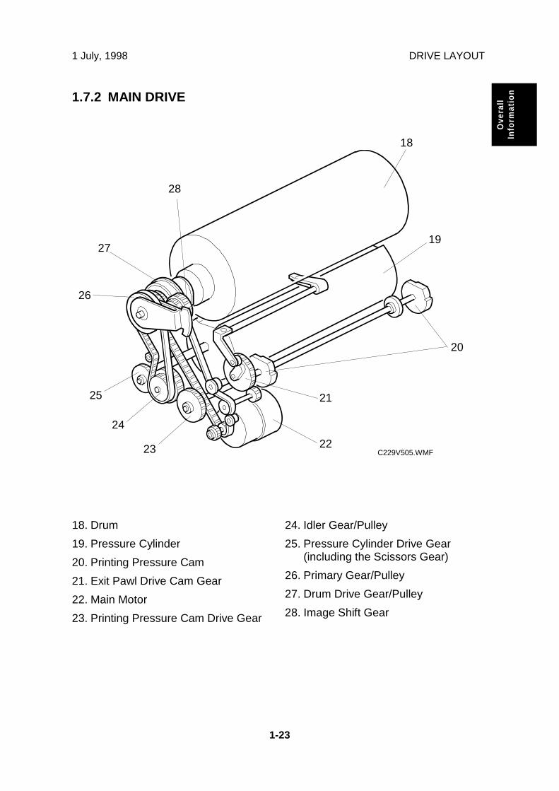
ion1.7.2 MAIN DRIVE
18. Drum
19. Pressure Cylinder
20. Printing Pressure Cam
21. Exit Pawl Drive Cam Gear
22. Main Motor
23. Printing Pressure Cam Drive Gear
24. Idler Gear/Pulley
25. Pressure Cylinder Drive Gear(including the Scissors Gear)
26. Primary Gear/Pulley
27. Drum Drive Gear/Pulley
28. Image Shift Gear
C229V505.WMF
18
19
20
2223
24
25
26
27
28
21

1 July, 1998 SCANNER AND OPTICS
2-1
Det
aile
dD
escr
ipti
ons
2. DETAILED SECTION DESCRIPTIONS
2.1 SCANNER AND OPTICS
2.1.1 OVERVIEW
The exposure lamp, a xenon lamp [A], illuminates the original. The 1st, 2nd, and3rd mirrors, and a lens [B] reflect the image onto a CCD (Charge Coupled Device)[C].
The 1st scanner [D] consists of the exposure lamp, a reflector [E], and the 1stmirror [F].
A DC power supply energizes the exposure lamp to avoid uneven light intensitywhen the 1st scanner moves in the sub-scan direction. The entire exposure lampsurface is frosted to ensure even exposure in the main scan direction.
The reflector reflects light with almost equal intensity, to reduce shadows on pastedoriginals.
C229D094.WMF
[A] [C]
[B][D]
[E]
[F]

SCANNER AND OPTICS 1 July, 1998
2-2
2.1.2 SCANNER DRIVE
A stepper motor drives the scanner. The scanner drive motor [A] drives the 1st and2nd scanners [B, C] through the timing belt [D], scanner drive pulley [E], scannerdrive shaft [F], and two scanner wires [G].
- Book mode -
The scanner drive board controls and operates the scanner drive motor. In full sizemode, the 1st scanner speed is 42.33 mm/s during scanning. The 2nd scannerspeed is half that of the 1st scanner.
In reduction or enlargement mode, the scanning speed depends on themagnification ratio (M: 0.50 to 2.00). The returning speed is always the same, inboth full size and magnification modes. Changing the scanner drive motor speedchanges the image length in the sub-scan direction. Image processing on the MPUboard accomplishes reduction and enlargement in the main scan direction.
SP6-011-1 changes the motor speed and therefore adjusts the magnification ratioin the sub-scan direction.
- ADF mode -
During scanning, the scanners are always in their home positions (when thescanner H.P sensor [H] detects the 1st scanner). The ADF motor feeds the originalthrough the ADF. In reduction/enlargement mode, changing the ADF motor speedchanges the image length in the sub-scan direction. Magnification in the main scandirection is done on the MPU board, in the same manner as book mode.
SP6-011-2 changes the ADF motor speed and therefore adjusts the magnificationratio in the sub-scan direction.
C229D095.WMF
[B][C]
[A]
[D]
[E] [F]
[E]
[H]
[G]
[G]
Rear
Front

1 July, 1998 SCANNER AND OPTICS
2-3
Det
aile
dD
escr
ipti
ons
2.1.3 ORIGINAL SIZE DETECTION IN PLATEN MODE
In Platen mode, the size of paper on the paper table usually determines the imagereading area for the original. If Reduction or Enlargement mode is used, themagnification ratio affects the image reading area.
However, for Auto Magnification, Image Rotation, or Image Repeat modescombined with Platen mode, the original width [A] and length [B] sensors detect theoriginal size.
The sensors for original size detection are in the optics cavity. There are fourreflective sensors in the 115V machines, and six reflective sensors in the 220/240Vmachines.
C229D120.WMF
C229D096.WMF C229D116.WMF
[A]
[B]
[C] [C]
SCANNER AND OPTICS 1 July, 1998
2-4
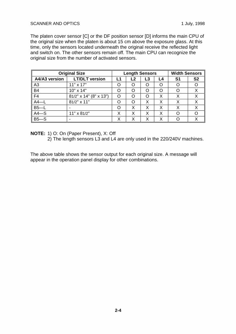
The platen cover sensor [C] or the DF position sensor [D] informs the main CPU ofthe original size when the platen is about 15 cm above the exposure glass. At thistime, only the sensors located underneath the original receive the reflected lightand switch on. The other sensors remain off. The main CPU can recognize theoriginal size from the number of activated sensors.
Original Size Length Sensors Width SensorsA4/A3 version LT/DLT version L1 L2 L3 L4 S1 S2A3 11" x 17" O O O O O OB4 10" x 14" O O O O O XF4 81/2" x 14" (8" x 13") O O O X X XA4—L 81/2" x 11" O O X X X XB5—L - O X X X X XA4—S 11" x 81/2" X X X X O OB5—S - X X X X O X
NOTE: 1) O: On (Paper Present), X: Off2) The length sensors L3 and L4 are only used in the 220/240V machines.
The above table shows the sensor output for each original size. A message willappear in the operation panel display for other combinations.
1 July, 1998 IMAGE-PROCESSING
2-5
Det
aile
dD
escr
ipti
ons
2.2 IMAGE-PROCESSING
2.2.1 OVERVIEW
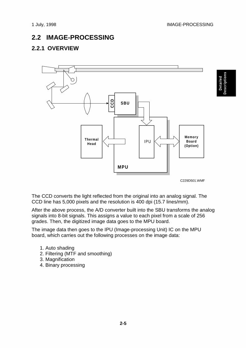
The CCD converts the light reflected from the original into an analog signal. TheCCD line has 5,000 pixels and the resolution is 400 dpi (15.7 lines/mm).
After the above process, the A/D converter built into the SBU transforms the analogsignals into 8-bit signals. This assigns a value to each pixel from a scale of 256grades. Then, the digitized image data goes to the MPU board.
The image data then goes to the IPU (Image-processing Unit) IC on the MPUboard, which carries out the following processes on the image data:
1. Auto shading2. Filtering (MTF and smoothing)3. Magnification4. Binary processing
SBU
ThermalHead IPU
MPU
MemoryBoard
(Option)
CC
D
C229D501.WMF

IMAGE-PROCESSING 1 July, 1998
2-6
2.2.2 AUTO BACKGROUND CORRECTION
Auto background correction mode can be used in Photo/Letter, Photo, and Tintmodes. The default setting does not allow the user to select auto backgroundcorrection mode. (Use SP 2-31 to enable this mode.)
Auto background correction prevents the background of an original from appearingon copies.
While scanning the original, the background density detection area [A] is alsoscanned. This area [A] is a narrow strip at the start of the main scan line, as shown.As the scanner scans down the page, the IPU on the MPU detects the peak whitelevel for each scan line, within this narrow strip only. From this peak white level, theIPU determines the reference value for the A/D conversion for the scan line. TheIPU then sends the reference value to the reference controller on the SBU.
When an original with a gray background is scanned, the density of the gray areais the peak white level density. Therefore, the original background will not appearon copies. This feature corrects any changes in background density down thepage, because peak level data is taken for each line scanned.
C229D097.WMF
[A]

1 July, 1998 IMAGE-PROCESSING
2-7
Det
aile
dD
escr
ipti
ons
2.2.3 AUTO SHADING
There are two auto shading methods: black level and white level correction. Autoshading corrects errors in the signal level for each pixel.
- Black Level Correction -
The CPU reads the black dummy data from one end of the CCD signal (64 pixelsare blackened at the end) and takes an average of the black dummy data. Then,the CPU deletes the black level value of each image pixel.
- White Level Correction -
The machine reads a reference waveform from the white plate, before scanning theoriginal. The average of the white video level for each pixel is stored as the whiteshading data in the IPU.
The IPU chip corrects the video signal information for each pixel obtained duringimage scanning.
C229D504.WMF

IMAGE-PROCESSING 1 July, 1998
2-8
2.2.4 FILTERING AND MAIN SCAN MAGNIFICATION/REDUCTION
Overview
Filtering and main scan magnification process the image data after auto shading.However, to reduce moire in the image, the processing order depends on thereproduction ratio, as follows:
1) Reduction and Full sizeMain Scan Reduction → Filtering
2) EnlargementFiltering → Main Scan Magnification
Filtering
The MTF and smoothing filters are software filters that enhance the desired imagequalities of the selected original mode.
The MTF filter, used in all modes except Tint mode (which uses the smoothingfilter), sharpens the image.
SP6-082 adjusts the filter strengths for MTF mode.
The diagram below shows how the number stored in the SP mode afects thestrength of the filter.
NOTE: 1) Do not set the filter strength number to 1. Abnormal images may result.2) The smoothing filter strength is not adjustable.
11 8 2
C229D505.WMF

1 July, 1998 IMAGE-PROCESSING
2-9
Det
aile
dD
escr
ipti
ons
Main Scan Magnification/Reduction
The IPU chip handles reduction and enlargement in the main scan direction.NOTE: Changing the scanner speed accomplishes reduction and enlargement in
the sub-scan direction.When making a copy using the ADF, the magnification circuit creates a mirrorimage. This is because the scanning starting position in the main scan direction isat the other end of the scan line in ADF mode (as compared with platen mode). Inplaten mode, the original is placed face down on the exposure glass, and thecorner at [A] is at the start of the main scan. The scanner moves down the page. InADF mode, the ADF feeds the leading edge of the original to the DF exposureglass, and the opposite top corner of the original is at the main scan start position.
To create the mirror image, the CPU stores the main scan line data in the LIFO(Last In First Out) memory on the MPU, from the last pixel. When loading the mainscan line data from the LIFO memory, the CPU loads the first pixel of the mainscan line.
C229D506.WMF

IMAGE-PROCESSING 1 July, 1998
2-10
2.2.5 BINARY PROCESSING
In the IPU chip, the 8-bit data is converted into 1-bit data for black or white pixels.The binary processing for the letter mode is different from that for the photo modeand the letter/photo mode as follows:
1) Letter mode: Binary processing2) Letter/Photo mode: Binary processing3) Photo mode: Binary processing + error diffusion + dithering
These processes are used as follows.
- Binary Processing with Gamma Curve Compensation -
This process converts each video signal level from 8-bit to 1-bit (black and whiteimage data) in accordance with a threshold value.
The threshold value changes based on a compensation curve (Gamma curve)which corresponds to selected image settings. For example, if a darker image isselected, a compensation curve, which converts each pixel value to a highernumber, is selected. This ensures accurate generation of the gray scale from blackto white.
- Error Diffusion - (Photo mode only)
The error diffusion process reduces the difference in contrast between light anddark areas of a halftone image. This process corrects each pixel using thedifference between it and surrounding pixels. It then compares the corrected pixelswith the error diffusion matrix.
- Dithering - (Photo mode only)
Dithering compares each pixel with a pixel in the dither matrix. Several matrixesare available, to increase or decrease the detail on the copy.

1 July, 1998 IMAGE-PROCESSING
2-11
Det
aile
dD
escr
ipti
ons
2.2.6 OPTIONAL MEMORY BOARD
The optional memory board, or editing function board, has 4-Mbyte RAM, whichcorresponds to the amount of memory required for an A3 original. This enables thefollowing image editing functions.
- Memory Combine Mode -
Combined images of 4, 8, or 16 originals are printed on the same sheet of paper.
- Overlay -
Overlay merges two different originals onto the same sheet of paper.
- Stamp Printing Mode -
This mode enables stamping modes such as, the date, page number, presetmessage, and user custom stamps.
- Make-up Printing Mode -
The user makes command sheets to specify how various areas of the original willbe processed. The user must be sure to scan the command sheets before theoriginal. The image-processing chip in the MPU modulates the image data for thecommand sheet and then stores the modulated command data on the memoryboard.
The image data for the original is also converted and modulated. The MPU editsthe modulated image data, the stored command area data, and the backgroundpattern.
Positive/Negative can be used with this mode.
- Report Print Mode -
This mode prints the following data:
• User reports• Jam and error counter data• The number of people in each class set by the user• Number of prints and masters for each user code account• SP mode data for service
- Image Rotation Mode -
When the orientation for the original differs from the paper selected, the machineautomatically rotates the original image 90 degrees to match the paper orientation.
SP 2-150 can disable this mode.

IMAGE-PROCESSING 1 July, 1998
2-12
2.2.7 THERMAL HEAD
Specifications• Length 292.6 mm• Number of thermal head elements 4608• Density of thermal head elements 400 dpi
Thermal Head Control
The thermal head contains heating elements at a density of 400 dpi. The thermalheating elements melt the over-coating and polyester film layers of the master, inaccordance with the image signal for each pixel.
This model has an independent power supply unit for the thermal head. It appliespower (VHD) to the thermal heating elements. The power source varies from onehead to another since the average resistance of each element varies. Therefore,when replacing the thermal head or power supply unit, it is necessary to readjustthe applied voltage to the specific value for the thermal head.
Thermal Head Protection
The thermistor on the thermal head provides thermal head protection, preventingthe thermal head from overheating when processing a solid image. The CPUchecks for any abnormal condition when the Start key is pressed; it displays an SCcode on the operation panel as follows:
SC Code Conditions DetectingComponent
SC03-03 Over 54°C ThermistorSC03-02 Under - 20°C (Normally in this case, the thermistor
is open, or a related connector is disconnected.)Thermistor
SC03-01 When the pulse width that controls the thermalhead energy becomes abnormal, master makingstops and generates this SC code.
MPU
SC03-00 The CPU monitors the ID signal from the thermalhead, which identifies the thermal head type. If anabnormal ID signal is detected just after installingthe master making unit in the machine, it generatesthis SC code.
MPU

1 July, 1998 IMAGE-PROCESSING
2-13
Det
aile
dD
escr
ipti
ons
Remarks for Handling the Thermal Head
Pay careful attention to the following remarks when servicing:
- Other Remarks -
Avoid using the machine under humid conditions. Moisture tends to condense onthe thermal head, damaging the elements.
• Remove any foreign materials fromthe platen roller.
• Remove foreign materials.
• Do not touch the master filmsurface with bare hands.
• Connect and disconnect the connectorscarefully. Keep them horizontal andfirmly reconnect them.
• Do not touch the connectorterminals with bare hands, toprevent damage from staticelectricity.
Connector
Master
PlatenRoller
Thermal Head
PSU
MPU
• Adjust the voltage supplied to match thespecified value for the thermal head.
• Do not touch the surfacewith bare hands. If thisoccurs, clean the surfacewith alcohol.
• Do not damage theheating elements.
• There are some ICs insidethe metal cover. Do not pushthe cover down.

MASTER EJECT 1 July, 1998
2-14
2.3 MASTER EJECT
2.3.1 OVERVIEW
The master remains wrapped around the drum to prevent the ink from drying.Therefore, making a new master begins from the master ejecting process.
When the Start key is pressed to scan the original, the drum rotates from the homeposition to the master eject position. As soon as the drum reaches the master ejectposition, the drum master clamper [C] opens. The drum position lock mechanismlocks the drum at this position to prevent the drum from moving during masterejection.
At the same time, the master pick-up roller [A] touches the drum, picking up theleading edge of the master on the drum. Then, the master is caught by the upperand lower master eject rollers [B] and is transported into the master eject box [E].
When the trailing edge of the master passes the roller, the pressure plate [D]begins to compress the master into the box.
Before this process is complete, the original scanning and master making hasalready started, and the drum will then rotate to the master making position.
C229D106.WMF
[E]
[D]
[C]
[B]
[A]

1 July, 1998 MASTER EJECT
2-15
Det
aile
dD
escr
ipti
ons
2.3.2 MASTER EJECT MECHANISM
Overview
Two photosensors (the 1st and 2nd drum position sensors) and the feeler on therear drum flange determine the drum position. The drum is at the home positionwhen the feeler actuates the 1st drum position sensor. At this position, the drummaster clamper, which clamps the leading edge of the master onto the drum, islocated at the bottom of the drum. (For details, refer to Drum Drive Mechanism inthe Drum section.)
The drum turns 114.5 degrees from the home position to reach the master ejectposition (there is no sensor for master eject position detection – main motorencoder pulses only). As soon as the drum stops, the clamper motor [B] starts toopen the drum master clamper [F]. The master pick-up roller [D] moves against thedrum at the same time, because it is connected through an idle gear.
A link plate connects the drum guide [E] to the clamper opening arm [A]. So, whenthe arm moves, the drum guide also moves, and this locks the drum position.
NOTE: 1) To lock the drum, the drum guide catches one of two studs at differentpositions on the drum. The drum guide catches one stud at the mastereject position [C], and the other stud at the master making position.
2) The drum master clamper also opens when the drum is at the mastermaking position. However, it uses a different clamper-opening arm. Fordetails, refer to the Master Making section.
3) Do not clean the inside of the master clamper with alcohol or otherstrong solvents. Use a cloth dampened with water. This prevents themagnetic force from weakening. This part requires periodic cleaning.
C229D112.WMF
[C]
[B]
[E]
[A]
[D]
Rear
[F]
Front

MASTER EJECT 1 July, 1998
2-16
Drum Lock Mechanism
The clamper motor drivesthe drum guide [C]. Theclamper closed positionsensor [A] and clamperopen position sensor [B]monitor the position of thedrum guide.
When the drum reachesthe master eject position,the drum guide moves untilthe clamper open positionsensor [B] is actuated thendeactuated (the actuatormust go through thesensor). This engages thestud on the rear drumflange.
Before the drum startsrotating to the mastermaking position, the drumguide returns to the homeposition. The clamperclosed position sensor [A] determines this position.
NOTE: The same drum guide also moves when the drum is at the master makingposition. (There is another stud on the rear drum flange, which is used tosecure the drum at the master making position.)
A link plate at the master eject position synchronizes the master clamperwith the drum guide movement.
To open the clamper, the drum guide (with the clamper opening arm) mustmove a greater distance than at the master making position. Therefore, atthe master eject position, the drum guide moves (to open the masterclamper) until the clamper open position sensor [B] turns on (interrupted bythe feeler) and then turns off again, as shown in the diagram. Refer to theMaster Feed section to compare the two mechanisms.
C229D107.WMF
[B]
[A]
[C]
Rear
Front

1 July, 1998 MASTER EJECT
2-17
Det
aile
dD
escr
ipti
ons
Master Pick-up Roller Drive and Master Clamper Open
When the clamper motor opens the drum master clamper [B], the master pick-uproller [A] contacts the leading edge of the master on the drum. The clamper motormoves the master pick-up roller against the drum through the idle gear [D], whiledriving the clamper opening arm [C].
At the same time as the drum master clamper [B] closes after the master is pickedup, the master pick-up roller [A] also moves back to the original position.
The drum guide is also released at the same time. The drum continues turningtowards the master making position while the used master is removed from thedrum.
C229D081.WMF
[A]
[B]
[D]
[C]
Rear
Front

MASTER EJECT 1 July, 1998
2-18
Master Eject and Transportation
The master pick-up roller [A] and the upper and lower master eject rollers [B] allturn together. They start turning as soon as the drum reaches the master ejectposition.
The rollers stop once the leading area of the master is picked up from the drum.(The master eject sensor detects this.) Then, when the drum starts turning, theyturn on again to feed the ejected master to the eject box while the drum turnstowards the master making position.
The master eject sensor (not shown) is located just under the lower master ejectroller, and it monitors the master feeding. If the master is not properly picked up,i.e. it does not activate the sensor; the operation panel displays a master eject jammessage.
C229D082.WMF
[A]
[B]
Rear
Front

1 July, 1998 MASTER EJECT
2-19
Det
aile
dD
escr
ipti
ons
Master Eject Roller Unit Drive
The master eject motor [A] turnsthe master pick-up roller [B] withthe upper and lower master ejectrollers [C].
When the unit is slid out(explained below), the joint [D]disengages.
Master Eject Roller Unit Slide-out Mechanism
The master eject roller unit[E] can be slid out of themachine as shown for easymaster jam removal.
The unit contains the masterpick-up roller, upper andlower master eject rollers,and the master eject sensor.
C229d513.WMF
C229D083.WMF
[E]
[A]
[B]
[D]
[C]

MASTER EJECT 1 July, 1998
2-20
Master Eject Box Mechanism
The user can slide the master eject box out from the operation side of the machine.The front handle of the box [A] has a lock mechanism as shown above.
The master eject box contains a pressure plate [B], which compresses the ejectedmasters in the box. The pressure plate also works as a guide plate feeding theejected master into the box.
An independent dc motor, the pressure plate motor, drives the pressure plate. Themotor is in the pressure plate drive unit, on the rear frame of the machine separatefrom the master eject box.
When the master eject box is slid out, the joint [D] for the pressure plate drivedisengages. At the same time, the lock lever [C] turns, due to tension from aspring, to hold the pressure plate [B] in the home position.
When the master eject box is re-installed, the drive joint [D] is connected and thepressure plate lock lever [C] is released as shown above.
C229D085.WMF
C229D092.WMF
[A]
[B]
[D]
[C]

1 July, 1998 MASTER EJECT
2-21
Det
aile
dD
escr
ipti
ons
The ejected masters in thebox can be taken out bysliding the eject lever [A]. Theinner bottom case [C] movestowards the rear of the box.
Masters are ejected from anopen door at the rear of thebox. The side opposite theeject lever side [A] of theinner bottom case isconnected to a belt [B]. Thishelps the inner bottom casemove smoothly.
When the master eject box isremoved, a push switch (theeject box set sensor) turnsoff, and the operation paneldisplays a message.
C229D084.WMF
[A]
[B][C]

MASTER EJECT 1 July, 1998
2-22
2.3.3 PRESSURE PLATE DRIVE MECHANISM
Overview
There are three phases.
• HomingAt power on or when recovering from an error or jam, the machine makes surethat the pressure plate is at home position. This is because, if certain errorsoccur, the pressure plate may not be in the home position at the start of a job
• Master ejectionThe pressure plate rotated into a position where it can act as a feed guide for theused master on its way to the eject box.
• CompressionThe pressure plate compresses the master into the box.
Drive
The pressure plate motor [A] drives the pressure plate [B] through the pressureplate gear [C]. This gear contains actuators for the home position sensor [D] andthe limit position sensor [E]. These two sensors monitor the pressure plate position.
The diagram shows a front view of the mechanism. The actuators are on the rearof the pressure plate gear, which is shown as see-through for ease of viewing.
C229D514.WMF[A] [B]
[C]
[D] [E]

1 July, 1998 MASTER EJECT
2-23
Det
aile
dD
escr
ipti
ons
Homing Operation
At power on or when recoveringfrom an error or jam condition, themachine carries out the pressureplate homing operation.
If certain errors occur, thepressure plate may not be in thehome position. The homingoperation starts by turning thepressure plate toward the drumand then it returns to the homeposition.
The homing operation is asfollows:
1. The pressure plate turnsclockwise (as seen from theoperation side) until both thepressure plate HP sensor [A]and the limit position sensor[B] are actuated.
2. As shown in the upper rightdiagram, the pressure plate turnscounterclockwise until the homeposition sensor [A] is actuatedtwice then de-activated. Thestatus of the sensor [A] changes:on ⇒ off ⇒ on ⇒ off.
3. The pressure plate has justslightly passed the home position.Then, as shown in the lower rightdiagram, the pressure plate againturns clockwise to return to theexact home position. The homeposition sensor status changesnow from: off ⇒ on ⇒ off.
C229D089.WMF
C229D114.WMFHomePositionPassed the home
position slightly
[A]
[B]
Passed the homeposition slightly
Master EjectReady Position
[A]
[B]

MASTER EJECT 1 July, 1998
2-24
Shift to the Master EjectPosition
When the Start key is pressed tomake a new master, the drumturns to the master eject position.During this period, the pressureplate travels to the master ejectready position.
The pressure plate turnsclockwise (as seen from theoperation side) until both thepressure plate HP sensor [A] andthe limit position sensor [B] areactuated.
Ejected Master Compression
When the ejected master has been fed to the master eject box, the pressure platecompresses the master. During this operation, the machine can recognize how fullthe eject box is by monitoring the lower limit and home position sensors.
When there are no or very few masters in the box
If there are no or only a few mastersin the box, the pressure plate canmove to its lowest position. Thepressure plate limit position sensordetects this position.
The pressure plate turnscounterclockwise from the mastereject ready position until the limitposition sensor [B] has been actuatedtwice. The sensor status changes:on ⇒ off ⇒ on.
The pressure plate stays at the lowerlimit position for 2 seconds, thenreturns to the home position.
C229D086.WMF
C229D087.WMF
[A]
Lower LimitPosition
[A]
[B]
HomePosition
Master EjectReady Position

1 July, 1998 MASTER EJECT
2-25
Det
aile
dD
escr
ipti
ons
When there are a lot of masters
If there are a lot of used masters inthe box, the pressure plate cannotmove to the lower limit position.
If the lower limit position sensor [B]is not actuated within 7 secondsafter the pressure plate startstraveling from the master eject readyposition, the pressure plate motorstops.
The pressure plate stays in thesame position for 2 seconds tocompress the masters. Then, itreturns to the home position.
There is a torque limiter [C] built intothe gear. When the built-up mastersin the box block pressure platemovement, the torque limiter allowsthis gear to slip.
Master Box Full Detection Mechanism
As explained above, the pressureplate motion range narrows as theejected masters build up in the box.The stopping position of the pressureplate therefore gets closer to thehome position.
When the pressure plate cannot travelpast the master box full position fromthe master eject ready position, thismeans that the master box is full.
In this case, the home position sensor[A] remains actuated as shown on theright.
The home position sensor statuschanges (from the master eject readyposition): on ⇒ off ⇒ on ⇒ off ⇒ on,and stays on. This means the masterbox is full and the operation paneldisplays a message.
C229D108.WMF
C229D088.WMF
[B]
[A]
[C]MasterCompressionPosition
[A]
Master BoxFull Position

MASTER EJECT 1 July, 1998
2-26
Pressure Plate Operation Timing Chart
HP Sensor
Limit PositionSensorPressure PlateMotor
This timing chart shows how the machine counts the number of home positionsensor on and off edges to check if the eject box is full or if the mechanism isjammed.
The signal is checked when:
• The limit position sensor turns on – this is when the pressure plate has turned allthe way to the lower limit position inside the box, which is only possible if the boxis fairly empty.
• At 6 s after the motor turns on
Drum Master Box Direction Drum Direction
HP EjectPosition
Compressing Position(Stays for 2 seconds)
HP Returned
Does not reach here after 6 seconds⇒ Motor locked
Check when rotating in themaster box direction
- Check Timing -When one of the followingoccurs:
1. When the Limit PositionSensor turns on.
2. 6 seconds after the motorturns on.
Number of HP Sensor On or Off Edges(The first ‘on’ edge is just after the motorstarts.)
• 5 times ⇒ Normal• 4 times ⇒ Master box full
• Less than 4 ⇒ Pressure plate locked(SC06-00 lights)

1 July, 1998 MASTER FEED
2-27
Det
aile
dD
escr
ipti
ons
2.4 MASTER FEED
2.4.1 OVERVIEW
A: Master Edge Sensor G: Master Roll
B: Tension Roller H: Master End Sensor
C: Platen Roller I: Master Vacuum Fans
D: Thermal Head J: Master Buffer Duct
E: Master Set Roller K: Cutter
F: Master Set Sensor L: Master Feed Control Roller
Original scanning starts when an original is set and the Start key is pressed.Master making begins at the same time. Although master ejecting is done first,scanning starts very soon after.
The master is a low fiber content paper coated with a thin heat-sensitive film. Theheating elements of the thermal head [D] burn the film to copy the scanned image.
The master is fed while the thermal head develops the image on it. The mastervacuum fans [I] temporarily suck the fed master into the master buffer duct [J]. Thisis done because the used master is still being ejected from the drum. When thedrum comes to the master making position, the master is fed to the drum and thedrum master clamper on the drum clamps the master.
The drum then turns to wrap the master around the drum. When the master hasbeen pulled out of the duct and is pulled tight at the cutter, the cutter [K] cuts themaster.
At the same time as the master is wrapping, a sheet of paper, called the trial print,is fed. This ensures that ink transfers to the master on the drum, and that there is asufficient density of ink for the print run to start. The drum then returns to the homeposition and is ready for printing.
C229D115.WMF
[J]
[I]
[D][E]
[G]
[H]
[K]
[C][B]
[A]
[F][L]

MASTER FEED 1 July, 1998
2-28
2.4.2 MASTER SET MECHANISM
Master Roll Set
The master set sensor [A]checks to see if the master rollwas installed properly. Afterinserting the master making unit,the sensor detects the leadingedge of the master. The masteris fed in until the leading edgereaches the master feed controlroller.
Master Feed and Stop Control (Edge Detection)
While the master is being fedafter a roll is put in the machine,the master edge sensor [B]checks the leading edge of themaster.
The master is fed 18 mm moreafter the master edge sensor [B]is activated. It has now beencaught by the master feedcontrol roller [C] and it stops.This is the stand-by position formaster making.
While the master is fed, theplaten roller pressure, which isused to press the master against the thermal head, is repeatedly applied andreleased using the platen pressure release mechanism. This prevents master skewor creasing after a roll has been put in the machine. A later section will describethis process in more detail.
C229D102.WMF
C229D103.WMF
[A]
[C][B]

1 July, 1998 MASTER FEED
2-29
Det
aile
dD
escr
ipti
ons
Master Buffer Duct Entrance Control
While the master is beingtransported to the masterfeed control roller [A], theduct entrance solenoid [C]closes the master bufferduct entrance plate [B]. Thisprevents the duct entrancefrom catching the leadingedge of the master.
After the master feedcontrol roller [A] catches themaster leading edge, theentrance plate is opened.(The normal position of theentrance plate is open.)
Master End Detection
There is a solid-fill black area atthe end of the master roll. Whenthe master end sensor [D]detects this area, the operationpanel displays the master endmessage.
As the master is semi-transparent, the sensor candetect the black area at the endof the roll when there are still afew layers of clear master on theroll. When this happens, masterroll near-end is detected.
C229D004.WMF
C229D104.WMF
[A]
[C]
[B]
[D]
Rear
Front

MASTER FEED 1 July, 1998
2-30
2.4.3 MASTER MAKING AND FEED MECHANISM
Master Feed Mechanism
The master feed motor [F], a stepper motor, drives the master feed control [A],tension [B], platen [C] and master set [D] rollers.
The tension roller feeds the master slightly faster than the platen roller, to preventthe master from creasing. Therefore, the master between the platen roller andthermal head is always under tension.
There is a torque limiter [E] built into the tension roller drive gear. This allows thetension roller to become free from the master feed motor drive when the master isunder excessive tension, to prevent damage to the master.
NOTE: Strips of mylar under each master feed roller prevent the master frombeing wrapped around the rollers. Be careful not to damage or set themylars in the incorrect position because they damage easily. For details,refer to the Replacement and Adjustment section.
C229D003.WMF
[A]
[B]
[D]
[C]
[F]
[E]
RearView

1 July, 1998 MASTER FEED
2-31
Det
aile
dD
escr
ipti
ons
Platen Roller Pressure Release
The platen release motor [A] gives half a turn to the platen release cam [B] to applyor release the platen roller [C] pressure. As the motor turns, the actuator on thegear interrupts the platen release sensor [D]. When the pressure is released, theactuator interrupts the sensor.NOTE: When installing the gear with the actuator, remember that the setting
position depends on the platen release cam position. For details, refer tothe Replacement and Adjustment section.
Just before master making, the platen release motor starts turning until the sensoris inactive; this indicates that the platen pressure is now applied to prepare formaster making.
When master making is complete, the motor turns again until the sensor isactivated, releasing the platen pressure. This allows the user to remove a jammedmaster. Also, in standby mode, there is no pressure between platen roller andthermal head, so that the user can take out the master.
As explained in “Master Feed and Stop Control,” the platen roller pressure isrepeatedly applied and released to prevent master skew or creasing after a roll hasbeen put in the machine. To do this, the motor continues turning for 3 seconds.
C229D002.WMF
[B]
[A]
[D]
[C]
RearView

MASTER FEED 1 July, 1998
2-32
Master Buffer Mechanism
To minimize master processing time, the master is stored in the master buffer duct[A] after the thermal head transfers the image to it. The stored master is fed outfrom the duct when the drum reaches the master making position after masterejecting.
The master buffer duct is located under the master feed path. A two-level chamberinside the duct can hold a sufficient length of the master for A3 printing.
As soon as master making starts, the three master vacuum fans [B] start turning,creating suction to guide the master into the duct [A]. At this time, the master feedcontrol roller has already caught the leading edge of the master. This roller doesnot start turning until the drum reaches the master making position and the masterclamper opens (because the master feed clutch disconnects the master feed motordrive).
The master is fed while the thermal head writes the image on it. As the leadingedge of the master stops, the suction guides the fed master into the master bufferduct and stores it as shown in the above diagram.
When the drum comes to the master making position, the master feed control rollerstarts turning and feeds out the master that is stored in the duct.
C229D000.WMF[A]
[B]
Rear
Front

1 July, 1998 MASTER FEED
2-33
Det
aile
dD
escr
ipti
ons
2.4.4 WRAPPING THE MASTER AROUND DRUM
Drum Lock and Master Clamper Open
As explained in the Master Eject section, the drum guide [A] holds the drum at themaster eject and master making positions.
When the drum reaches the master making position, the drum guide moves toengage the stud [B] on the rear drum flange until the clamper open position sensor[C] is actuated. (The other stud was used for the master eject position.)
The master clamper opening arm [D] is just above the drum guide. The arm isdifferent from the one used for opening the master clamper at the master ejectposition. The clamper motor [E] drives the arm and opens the master clamper [F],in synchronization with the drum guide movement.
The drum guide moves (to open the master clamper) until the clamper openposition sensor is interrupted by the feeler. Then it stops immediately (unlike at themaster eject position of the drum) as shown in the diagram.
Before the drum starts turning to start wrapping the master on the drum, the drumguide returns to the home position until the clamper close position sensor [G] isactivated. The master clamper opening arm also returns, closing the masterclamper.
C229D091.WMF
[F]
[A]
[D]
[B]
[C]
[G]
[E]
Rear
Front

MASTER FEED 1 July, 1998
2-34
Master Feed Control Roller Mechanism
The master feed clutch [A] connects and disconnects the drive from the masterfeed motor to the master feed control roller [B]. The master feed control roller onlyturns in the following cases:
• When a master roll is put in the machine, the master is fed until the master feedcontrol roller catches the leading edge of the master.
• During master clamping, the master feed control roller turns and sends theleading edge to the clamper position.
• While the master is being wrapped around the drum, the master feed controlroller turns to feed the master, in synchronization with the drum rotation.
C229D090.WMF
[A]
[B]
Rear
Front

1 July, 1998 MASTER FEED
2-35
Det
aile
dD
escr
ipti
ons
Master Clamping and Wrapping around the Drum
The master feed clutch turns on to feed out the master from the master buffer duct.The master is fed out 31 mm and reaches the drum master clamper [A]. Themaster feed clutch turns off temporarily.
The master clamper is closed and the drum starts turning to wrap the masteraround the drum. At the same time, the master feed clutch turns on again to feedthe master, synchronizing it with the drum rotation.
When master making is complete and the master is stored in the master bufferduct, the drum turns continuously to wrap the master. The cutter cuts the masterwhen there is no master left in the duct, and the master at the cutter is stretchedtightly; this ensures a clean cut.
A sheet of paper, called the trial print, is fed at the same time as the masterwrapping. To ensure that ink transfers to the master on the drum, the drum rotatesat its lowest speed (16 rpm). This ensures that the print run starts up with asufficient ink density.
The drum then returns to the home position, ready for printing.
C229D006.WMF[A]
Rear
Front

MASTER FEED 1 July, 1998
2-36
Master Cut and Buffer Duct Entrance Control
When the thermal head hasfinished making the masterand the master has been fedout of the duct, the cutter [A]will cut the master.
In preparation for making thenext master, the leading edgeof the next master iscontinuously fed to themaster feed control roller [B].
The new master is fed 32 mmpast the cut position andstopped.
NOTE: As explained in“Master Feed andStop Control in 2.5.2Master SetMechanism,” themaster edge sensoronly controls themaster stop positionat the master feedcontrol roller after aroll is put into themachine.
The duct entrance platestays open, except in thefollowing two cases. Toclose off the duct, the ductentrance solenoid closesthe master buffer ductentrance plate [C].
• While the leading edge ofthe next master is beingfed to the master feedcontrol roller [B]
• After a roll is put in themachine (as explained in"2.5.2 Master SetMechanism").
C229D105.WMF
C229D005.WMF
[B]
[A]
[B]
[C]
Rear
Front

1 July, 1998 MASTER FEED
2-37
Det
aile
dD
escr
ipti
ons
Cutter Mechanism
The cutter motor [D] drives the screw shaft [A], moving the cutter holder [C] forwardand backward.
There are two cutter blades [B] in the holder. While the cutter holder [C] travels tothe front (the operation side of the machine), the blades cut the master. The cuttermotor keeps turning in one direction. However, the cutter holder returns to thehome position when it reaches the front end of the cutter unit because of the twodifferent spirals threaded on the screw shaft [A].
When the cutter holder reaches the home position, the cutter home position sensor[E] is activated by the holder and the motor stops.
C231D573.WMF
[D]
[E]
[C]
[A]
[B]
RearView

MASTER FEED 1 July, 1998
2-38
2.4.5 MASTER MAKING UNIT SLIDE-OUT MECHANISM
The master making unit can beslid out along the guide rails.
There are three connectors,which enable electrical contactfor the installed unit.
The master making unit setsensor [A] (a push switch)detects when the unit is out. Theoperation panel displays amessage in this case.
2.4.6 OPENING DOOR FOR MISFED MASTER REMOVAL
There is a jam removal dial tomanually rotate the master feedrollers. If pieces of the masterremain in the master buffer duct,open the door [B] to remove them.Normally, pieces of master do notremain in the duct. Therefore, thedoor is only for emergency cases.
C229D100.WMF
C229D101.WMF
[A]
[B]

1 July, 1998 DRUM
2-39
Det
aile
dD
escr
ipti
ons
2.5 DRUM
2.5.1 OVERVIEW
The drum surface is composed of a stainless-steel screen (metal screen [A]) andtwo layers of polyester screens (cloth screen [B]). In addition, a drum masterclamper [C] clamps the leading edge of the master wrapped around the drum.
Inside the drum are the ink roller [D] and doctor roller [E], which create a preciselymaintained gap, known as the doctor gap, to supply a thin layer of ink on thescreens and master [F].
This machine uses the drum idling roller [G] to supply ink onto the screens andmaster before printing. The length of time the machine was not in use determinesthe idling supply time. This ensures that the first print will have sufficient ink densityeven after the machine was not used for a long time.
C229D109.WMF
[E]
[D]
[G]
[C]
[A]
[B]
[F]

DRUM 1 July, 1998
2-40
2.5.2 INK SUPPLY AND KNEADING MECHANISM
Ink Cartridge Installation
The ink cartridge [A] is in the drum. Theink cartridge set sensor [B] (a pushswitch) detects the presence of the inkcartridge.
Ink Supply Mechanism
The whole ink supply mechanism isinside the drum. The ink pump motor [C]drives the ink pump [D], supplying inkfrom the ink cartridge to the ink roller [E]via the ink distributor [F].
Ink Pump Operation Monitoring
The ink pump sensor [G] monitors the number of pumps the ink pump piston levermakes. The feeler on the piston lever activates the sensor at each complete turn ofthe piston.
SP1-5 can be used to check the number of ink pump revolutions.
C229D010.WMF
C229D009.WMF
[B]
[A]
[C]
[D]
[G]
[F]
[E]

1 July, 1998 DRUM
2-41
Det
aile
dD
escr
ipti
ons
Ink Detection Board
Ink Detection Mechanism
The ink detecting pins [A] function as a capacitor electrode and detect thecapacitance between the ink [B] and doctor [C] rollers. The capacitance levelchanges with the ink level. When the ink level is high the pins touch ink, and thecapacitance increases. When the ink level is low the pins do not touch the ink andthe capacitance therefore decreases. Consequently, by detecting the capacitancebetween the pins, the ink supply motor maintains the ink level.
If the pins detect an insufficient amount of ink after activating the ink pump motorfor 40 seconds, a "no ink condition" is detected. Guidance is displayed on theoperation panel.NOTE: The ink supply mode is useful when installing a new drum. When the
“Economy Mode” key is pressed while holding down the “0” key, the drumturns 40 rotations, to supply ink inside the drum.
The ink detection board [D], which includes the ink detection circuit, is also insidethe drum. There are test pins (TP's) and a potentiometer (VR901) for ink detectionadjustment.
C229D011.WMF
C229D110.WMF
[C][B]
[A]
[D]
DRUM 1 July, 1998
2-42
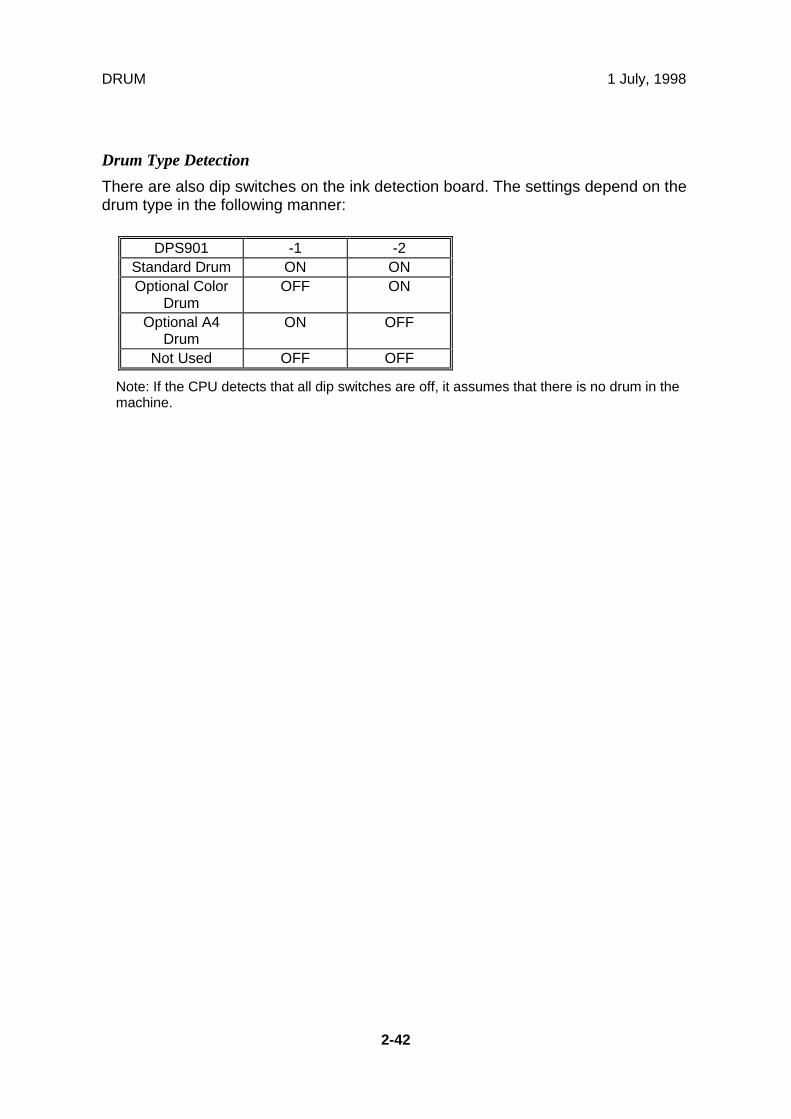
Drum Type Detection
There are also dip switches on the ink detection board. The settings depend on thedrum type in the following manner:
DPS901 -1 -2Standard Drum ON ONOptional Color
DrumOFF ON
Optional A4Drum
ON OFF
Not Used OFF OFF
Note: If the CPU detects that all dip switches are off, it assumes that there is no drum in themachine.

1 July, 1998 DRUM
2-43
Det
aile
dD
escr
ipti
ons
Ink Kneading Mechanism
A gear [C] on the drum shaft drives the ink [A] and doctor [B] rollers. The doctorroller spreads the ink evenly on the ink roller. The ink roller drive gear [D] has aone-way clutch to prevent the ink roller from being manually turned in the reversedirection.
The ink roller only touches the screen during the printing process. During theprinting process, ink passes to the paper through holes in the screens and themaster. This is because the pressure cylinder below the drum holds the drumscreen and the master against the ink roller during printing.
The ink roller blade [E] and separation plate [F] scrape off ink build-up on bothends of the ink and doctor rollers.
C229D012.WMF
C229D007.WMF
[C]
[B]
[A]
[D] [F]
[E]
Front
Rear

DRUM 1 July, 1998
2-44
Drum Idling Mechanism
Quality Start Mode
In Quality Start mode; the machine enters the drum idling mode before printing.This ensures that the first print has sufficient ink density even if the machine wasnot used for a long time.
The user selects Quality Start mode by pressing a key on the operation panel. Thenumber of idling rotations is fixed at 45. However, SP3-90 can change this number.NOTE: In Quality Start mode; the drum idling motion starts, before printing, when
the Start key is pressed. However, if there is no master on the drum, drumidling is not performed.Even if the Quality Start mode is active, and there is no master on thedrum, drum idling is skipped although the LED on the operation panel turnson. When printing for the next original starts, the machine enters drumidling mode if a large enough master is wrapped around the drum (it willnot be done for an A4 master on an A3 drum).
The drum idling roller [A] puts the ink onto the screens and master before printing.The idling roller motor [B] turns to press the drum idling roller against the innersurface of the drum screen [C]. The spring tension supplies additional force for this.
The cam [D] is turned by the motor, moving the drum idling roller towards the drumscreen. The actuator disk [F] interrupts the idling roller HP sensor [E] when thedrum idling roller is being used.
C229D013.WMF
[B]
[C]
[D]
[F]
[E][A]
Front
Rear

1 July, 1998 DRUM
2-45
Det
aile
dD
escr
ipti
ons
Auto Quality Start Mode
Auto Quality Start is done if the user does not select Quality Start mode. (It can bedisabled with a user tool.)
In Auto Quality Start mode, the idlingmotion depends on how long themachine was not in use and on thetemperature detected by thethermistor [A] in the drum.
The CPU detects a low temperaturecondition if the thermistor [A] reportsapproximately 15 °C or lower. If thedetected temperature is 28 °C orhigher, it is a high temperaturecondition.
The number of drum idling rotationsdepends on temperature and period ofmachine inactivity, as shown in thefollowing table.
NOTE: SP3-91 to 3-93 can changethe number of rotations for each of these conditions.
Period/Temperature
Less than 4hours
4 to 24 hours 24 to 72 hours Over 72 hours
High (28 °Cor higher)
0 0 0 15
Normal (15 to28 °C)
0 0 15 15
Low (15 °C orlower)
0 15 45 45
NOTE: The drum rotation speed during idling is fixed at 90 rpm.
C229D111.WMF
[A]

DRUM 1 July, 1998
2-46
Drum Rotation Speed during Idling
Whether the machine is in Quality Start mode or not, the drum idling roller isalways used for the trial print (the print to complete the master making), and for thefirst and second prints. If a low temperature condition is detected, the drum idlingroller is also used for the third print.
The drum rotation speed varies during this mode as shown in the table below. In allcases, the drum idling roller returns to home position when drum rotation speedreaches 75 rpm.
- Change of drum rotation speed (rpm) with temperature -
Temperature TrialPrint 1st Print 2nd
Print 3rd Print 4th Print 5thPrint
6thPrint
7thPrint
Normal orHigh
(above 15°C)
16IdlingRoller On
30IdlingRoller On
60IdlingRoller On
75IdlingRollerReturned
90 105 120 120
Low(below 15
°C)
16IdlingRoller On
16IdlingRoller On
30IdlingRoller On
60IdlingRoller On
75IdlingRollerReturned
90 105 120
NOTE: These figures apply to the highest printing speed (speed 5, which is at 120rpm).
1 July, 1998 DRUM
2-47
Det
aile
dD
escr
ipti
ons
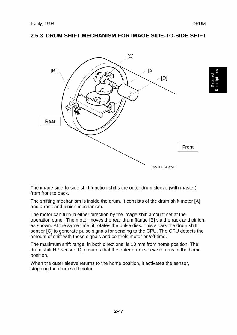
2.5.3 DRUM SHIFT MECHANISM FOR IMAGE SIDE-TO-SIDE SHIFT
The image side-to-side shift function shifts the outer drum sleeve (with master)from front to back.
The shifting mechanism is inside the drum. It consists of the drum shift motor [A]and a rack and pinion mechanism.
The motor can turn in either direction by the image shift amount set at theoperation panel. The motor moves the rear drum flange [B] via the rack and pinion,as shown. At the same time, it rotates the pulse disk. This allows the drum shiftsensor [C] to generate pulse signals for sending to the CPU. The CPU detects theamount of shift with these signals and controls motor on/off time.
The maximum shift range, in both directions, is 10 mm from home position. Thedrum shift HP sensor [D] ensures that the outer drum sleeve returns to the homeposition.
When the outer sleeve returns to the home position, it activates the sensor,stopping the drum shift motor.
C229D014.WMF
[B]
[C]
[A]
[D]
Rear
Front

DRUM 1 July, 1998
2-48
2.5.4 DRUM SET MECHANISM
Upper Handle and Lock
There are two grips [A, and B] tohold the drum.
When the upper grip [A] is pulled up,it releases the drum lockingmechanism.
Front Lock Lever
When the drum is set correctly and thefront lever [C] is raised, the drum is lockedinto position. The connector [D] allowselectrical contact for the drum components.
Drum Rotation Lock Mechanism
The rotation stopper [E] prevents thedrum from turning when it isremoved from the machine.
When the drum is replaced, contactwith the rear frame disengages thestopper [E] and releases the lock.
C229D015.WMF
C229D016.WMF
C229D017.WMF
[A]
[B]
[E]
RearView
[C]
[D]

1 July, 1998 DRUM
2-49
Det
aile
dD
escr
ipti
ons
2.5.5 DRUM DRIVE MECHANISM
The main motor [A] drives the drum via the timing belt. When the drum is set in themachine, the stud [B] on the joint disk engages the drum drive gear [C]. Thistransmits the main motor drive to the drum unit.
The main motor [C] has an encoder to send pulses to the main motor controlboard. The CPU monitors the pulses and controls the drum speed and stoppositions. The 1st and 2nd drum position sensors [D, E] check the position of thedrum. The actuator on the rear drum flange activates these sensors as the drumturns.
There are three drum stop positions: home, master eject, and master making. TheCPU starts counting the main motor encoder pulses when these sensors areactivated. Certain pulse counts are assigned to each drum stop position. The CPUcan stop the drum at the desired positions.
At the home and master making positions, the drum de-actuates the relevantsensor. This ensures that the drum stops in the exact position, even after high-speed rotation. The 1st drum position sensor corresponds to the home position andthe 2nd drum position sensor corresponds to the master making position.
C229D020.WMFC229D018.WMF
[A]
[E]
[D]
[C]
[B]
RearView

DRUM 1 July, 1998
2-50
2.5.6 MASTER DETECTION
The 1st drum master sensor[A] detects a master on thedrum.
If a master is on the drum, theblack patch [B] is covered andthe sensor detects the lightreflected from the master.Printing starts when the startkey is pressed. If an originalhas been set, the master isejected before making a newmaster.
If no master is on the drum, theblack patch is exposed. Theblack patch does not reflectlight back to the sensor. Themachine will skip the master eject process and immediately begin making a newmaster.
A similar sensor, the 2nd drum master sensor [C], is located just above the 1stdrum master sensor. This sensor determines if the master making processcorrectly wrapped the master around the drum.
The drum starts turning soon after the drum master clamper clamps the leadingedge of the master. The 2nd drum master sensor checks for the presence of themaster (master clamping error check). If a master is not detected, a clamping erroroccurred. The master feed stops, the drum returns to the home position, and themachine displays a master feed jam message.
The 1st drum master sensor cannot check for master clamping errors, because theblack patch has moved.
Both sensors use the same black patch [A] to detect the master.
NOTE: There are two black patches on the drum screen. Patch [D] does not facethe drum master sensors and is not used for master detection.
The surface of the patches is slightly higher than the surface of the rest ofthe drum screen. The extra patch ensures that the master pick-up rollercontacts the drum surface evenly at this part of the drum, resulting in evenpressure from the roller all across the drum.
C229D019.WMF
[A]
[B]
[C]
[D]

1 July, 1998 PAPER FEED
2-51
Det
aile
dD
escr
ipti
ons
2.6 PAPER FEED
2.6.1 OVERVIEW
Pick-up and Feed
The top sheet of paper on the paper table is first fed by the pick-up roller [D]. Then,it is separated by the paper feed roller [F] and the friction pad [E], and fed to theregistration rollers [A]. The upper and lower registration rollers feed the sheet to thedrum.
An independent stepper motor (the paper feed motor [C]) drives the pick-up rollerand paper feed roller. This allows more precise control than the usual mainmotor/magnetic clutch system.
Feed/Separation Pressure
The strength of the paper feed roller and the friction pad pressure against thepaper depend on the paper type selected at the operation panel. Each componenthas a separate dc motor to adjust the pressure. The operator is free fromcomplicated adjustments for paper feed and paper separation pressures.
Registration
Also, an independent stepper motor (the registration motor [B]) controls theregistration roller. The registration roller synchronizes paper feed timing with theimage on the drum. The registration roller starts rotating after the paper has comein contact with the rollers and has been aligned.
Paper feed timing around the registration roller is monitored by two different photo-sensors. One is located before the registration roller, and the other is after theregistration roller. These sensors are also essential for paper feed control.
C229D053.WMF
[B][D]
[E][F]
[A]
Rear
Front
[C]

PAPER FEED 1 July, 1998
2-52
2.6.2 PAPER FEED MECHANISM
The pick-up roller [C] and paper feed roller [A] are driven by the paper feed motor[B] as shown.
The top sheet of the paper is separated from the paper stack by the frictionbetween the roller and the friction pad [D], and fed to the registration roller.
The friction pad [D] is mounted on a block [E], and spring pressure is applied to thisblock. As explained later, the spring pressure is changed by a dc motor to adjustthe paper separation pressure.
There is a one-way clutch in the paper feed roller. When the roller stops and paperis fed by the registration rollers, the one-way clutch ensures that the paper feedroller does not resist the paper feed.
C229D054.WMF
C229D056.WMF
[A][B]
[C]
[D]
[E]
[A]
Rear
Front

1 July, 1998 PAPER FEED
2-53
Det
aile
dD
escr
ipti
ons
Since paper feed timing must be synchronized with pressure cylinder rotation (sothat the paper clamper on the pressure cylinder can catch paper’s leading edgeaccurately), the paper feed motor on timing is maintained by the feed start sensor[C].
A short time after the pressure cylinder [D] starts rotating, the actuator [A] on therear of the pressure cylinder activates the sensor. After a pre-determined duration,the paper feed process begins (this time will vary with the printing speed).
NOTE: There are two actuators: [A] and [B]. The actuator [B] is used to maintainthe registration motor start timing.
C229D118.WMF
[A]
[B]
[C]
[D]
RearView

PAPER FEED 1 July, 1998
2-54
2.6.3 PAPER FEED/SEPARATION PRESSURE ADJUSTMENT MECHANISM
Overview
The paper separation pressure and the paper feed pressure depend on the papertype selected at the operation panel. When the paper type is changed, two dcmotors automatically turn to change the pressure settings.
Paper Separation Pressure
The paper separation pressure is applied from the bottom of the friction pad block[A] by a spring on the friction pad base [E].
The direction of the paper separation pressure motor [B] turn depends on thesignal from the CPU. The rack [D] moves from side to side, moving the friction padbase up or down. This changes the spring pressure against the friction pad block.
The position of the rack [D] is detected by the separation pressure detection board[C].
C229D057.WMF
[A]
[B]
[C]
[D]
[E]

1 July, 1998 PAPER FEED
2-55
Det
aile
dD
escr
ipti
ons
Paper Feed Pressure
The mechanism is similar to the separation pressure control mechanism.
The feed pressure motor [E] rotates, pulling or releasing the spring [C] through therack [D]. The lever [F] moves up or down depending on the tension of the spring. Ifthe spring is pulled, the lever moves upwards, reducing the paper feed pressure.
The position of the rack [D] is detected by the feed pressure detection board (notshown), in a similar way as in the paper separation pressure control mechanism.
C229D055.WMF
[C]
[D]
[E]
[F]
Rear
Front

PAPER FEED 1 July, 1998
2-56
Paper Types
The user can select the paper type before starting the job. The feed and separationpressures used for the job will depend on the selected paper type (the machineautomatically adjusts these pressures to suit the selected paper type.
The possible paper type settings are standard, thick, and special. Two additionalsettings for paper types can be customized as 'user 1' and 'user 2'.
For the 'user 1' and 'user 2' paper types, the user can choose from 5 settings usinga user tool. The user tool settings give the machine a rough idea of what type ofpaper the user is using as types User 1 and User 2. The five user tool settings areas follows.
• Standard, no feed (Standard paper type, non feed likely)• Standard, double feed (Standard paper type, double feed likely)• Thick, no feed (Thick paper type, non feed likely)• Thick, double feed (Thick paper type, double feed likely)• Thick, medium (Thick paper type, with intermediate chances of double and non-
feed)
Pressure Settings for Each Paper Type
For each of these paper types (standard, thick, special, user 1, user 2), the userhas two settings: ‘Misfeed’ and ‘Double Feed’. Each of these two settings has threepossible values: Standard, Frequent, Very Frequent (the user selects one of thesedepending on how the machine is performing).
The pressures for each setting can be adjusted with SP mode (SP 6-90 to -99).The ‘feed pressure’ SP modes adjust the feed pressures applied for each of theuser’s three possible ‘misfeed’ settings, and the ‘separation pressure’ SP modesadjust the separation pressures applied for each of the user’s three possible‘double feed’ settings. For how to use these SP modes, refer to the Replacementand Adjustment section.
• SP6-90: Feed pressure, special paper• SP6-91: Feed pressure, normal paper• SP6-92: Feed pressure, thick paper• SP6-93: Feed pressure, user 1 paper• SP6-94: Feed pressure, user 2 paper• SP6-95: Feed pressure, special paper• SP6-96: Feed pressure, normal paper• SP6-97: Feed pressure, thick paper• SP6-98: Feed pressure, user 1 paper• SP6-99: Feed pressure, user 2 paper

1 July, 1998 PAPER FEED
2-57
Det
aile
dD
escr
ipti
ons
Other Factors affected by the selected Paper Type
The paper type selected for a job also affects the paper delivery wing position, andwhether the paper clamper on the pressure cylinder is used or not.
• SP6-100: Paper delivery wing position for standard, special, thick, user 1, anduser 2 type paper
• SP6-101: Paper clamp enable/disable for standard, special, thick, user 1, anduser 2 type paper
Default Settings
The following table shows the default settings for each paper type. For thepressure, the higher the SP mode value, the higher the pressure.
For details about the paper clamper, see ‘Pressure Cylinder’. For details about thewing guides, see ‘Paper Delivery’.
Feed pressure Separation pressure
Paper Type Std. Freq. V.Freq. Std. Freq. V.
Freq.
WingGuides
PaperClamp
Standard 3 5 6 2 4 6 Up YesThick 5 6 6 2 3 4 Down NoSpecial 3 5 6 1 3 4 Down NoUser 1 or 2:Standard, no feed
5 6 6 2 4 6 Up Yes
User 1 or 2:Standard, doublefeed
2 4 6 4 5 6 Up Yes
User 1 or 2:Thick, no feed
5 6 6 1 2 3 Down No
User 1 or 2:Thick, doublefeed
3 5 6 3 5 6 Down No
User 1 or 2:Thick, medium
3 4 5 2 4 6 Down Yes

PAPER FEED 1 July, 1998
2-58
2.6.4 PAPER REGISTRATION MECHANSM
Registration Roller Drive
The lower registration roller [A] is driven by a stepper motor [B] (the registrationmotor).
C229D058.WMF
[A]
[B]
Rear
Front

1 July, 1998 PAPER FEED
2-59
Det
aile
dD
escr
ipti
ons
Paper feed timing must be synchronized with the pressure cylinder rotation, so theregistration motor on timing is maintained by the feed start sensor [C].
A short time after the pressure cylinder [D] starts rotating, the actuator [A] on therear of the pressure cylinder activates the sensor. A pre-determined duration later(see Note 1 below), the registration motor starts turning to feed paper to the drumand pressure cylinder. After the printing paper is caught between the drum and thepressure cylinder, the registration motor stops.
NOTE: 1) The registration motor rotation speed is constant. However, when theoperator selects a higher or lower printing speed (to change the copyimage density), the drum and pressure cylinder rotation speed changes.The registration motor must feed the paper at the correct time for theleading edge to be caught by the paper clamper on the pressurecylinder. Therefore, the registration motor start timing after the paperfeed start sensor is activated depends on the printing speed selected.
2) There are two actuators: [A] and [B]. The actuator [B] is used tomaintain the paper feed motor start timing. (This was mentioned earlier,in ‘Paper Feed Mechanism’.)
Image Up/Down Shift Mode
In addition, the registration motor start timing is changed by pressing the imageposition keys on the operation panel (this is the image up/down shifting mode). Ifthe paper feed timing is delayed, the image is shifted forward.NOTE: The leading edge of the paper must be precisely caught by the paper
clamper on the pressure cylinder after leaving the registration rollers. Whenthe image up/down shifting mode is used, the position of the pressurecylinder changes through the image up/down mechanism, so theregistration motor start timing must change. (The drum stays at homeposition.) For details of the mechanism, refer to "2.10 Image Up/DownShifting" section.
C229D119.WMF[A]
[B]
[C]
[D]
RearView
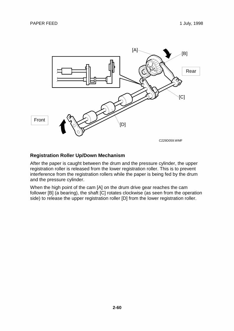
PAPER FEED 1 July, 1998
2-60
Registration Roller Up/Down Mechanism
After the paper is caught between the drum and the pressure cylinder, the upperregistration roller is released from the lower registration roller. This is to preventinterference from the registration rollers while the paper is being fed by the drumand the pressure cylinder.
When the high point of the cam [A] on the drum drive gear reaches the camfollower [B] (a bearing), the shaft [C] rotates clockwise (as seen from the operationside) to release the upper registration roller [D] from the lower registration roller.
C229D059.WMF
[A][B]
[C]
[D]
Rear
Front

1 July, 1998 PAPER FEED
2-61
Det
aile
dD
escr
ipti
ons
2.6.5 PAPER FEED CONTROL MECHANISM
The paper feed timing around the registration roller [A] is monitored by two differentphoto-sensors. The first is the paper registration sensor [C], which is located beforethe registration roller. The second sensor is the paper feed timing sensor [B], whichis located after the registration roller.
The paper registration sensor [C] detects the paper arriving at the registrationroller. The paper feed motor start timing is determined by this sensor. When thepaper comes into contact with the rollers, the motor remains stopped to create abuckle in the paper to obtain precise paper registration and to prevent paper skew.The motor starts turning a pre-determined period after the sensor is activated bythe paper. The sensor is also used to detect jams.
The paper feed timing sensor [B] is also used to detect paper jams. It is also usedto compensate for delays in paper feed caused by slippage at the registrationroller, as described below.
The CPU monitors the paper feed timing sensor after the registration motor startsturning. If the sensor turns on late, the CPU determines that there has beenslippage at the registration roller. Depending on the size of the delay, theregistration motor speeds up to recover the delay.
C229D060.WMF
[A]
[B]
[C]
Rear
Front

PAPER FEED 1 July, 1998
2-62
2.6.6 PAPER TABLE ANGLE ADJUSTMENT MECHANISM
There are two paper table openpositions: level, and 15 degreesupward slant. Normally the papertable is set at the level position.
The 15 degrees upward slantposition is used to feed specialtypes of paper, such as envelopes,which are difficult to feed at thelevel position. In the slantedposition, the tray capacity isreduced.
As the paper table [A] is loweredfrom the closed position, the pin onthe lever [C] engages the cutout inthe lock bracket [B]. Then, thepaper table stops at the levelposition.
When the paper table isslightly raised from the levelposition, the spring plate [D]pushes the lock bracket [B],and the pin on the lever [C]disengages. This stops thetable at the 15 degreesupward slant position.
C229D511.WMF
C229D061.WMF
[A]
[B]
[C]
[B] [D]
[C]

1 July, 1998 PAPER FEED
2-63
Det
aile
dD
escr
ipti
ons
2.6.7 PAPER TABLE OPEN DETECTION
When the paper table is open, the lever [A] activates the paper table set sensor [B].If the paper table remains closed and the sensor is not activated, guidance will bedisplayed on the operation panel.
C229D510.WMF
[A]
[B]

PAPER FEED 1 July, 1998
2-64
2.6.8 PAPER TABLE UP/DOWN MECHANISM
Paper Table Drive Mechanism
An independent dc motor, the paper table motor [A], drives the paper table. Whenthe motor turns, the pinion [B] turns along the rack [C], moving the paper table upor down.
To reduce noise, there is a shutter cover below the table, which is a combination of5 plates. The shutter closes the opening beneath the paper table when the table islifted up.
NOTE: Although each plate of the shutter looks similar, only the second and fourthplates [D] from the top are the same in shape. The other plates are alldifferent from each other. Be sure to re-assemble in the correct sequence.
C229D062.WMF
C229D063.WMF
[A]
[B]
[C]
[D]
Rear
Front

1 July, 1998 PAPER FEED
2-65
Det
aile
dD
escr
ipti
ons
Table Upper/Lower Limit Detection and Paper Height Control
When the paper table moves up, the top of the paper stack contacts the pick-uproller [B], lifting it up. Then, when the paper height sensor [A] is actuated, the papertable stops.
During a printing run, sheets are fed from the stack, and the pick-up roller lowers.When the paper height sensor is de-actuated, the paper table motor starts turningand lifts the paper table until the sensor is actuated again. In this way, the top ofthe paper stack remains at the same position during printing.
When the tray lowers, the lower limit position is detected by the paper table lowerlimit sensor (not shown), which is located beside the paper table motor.
C229D066.WMF
[A]
[B]

PAPER FEED 1 July, 1998
2-66
2.6.9 PAPER SIDE FENCE MECHANISM
The left and right side fences move together due to a rack and pinion mechanism.
The actuator plate [A] is attached to the rack. This actuates the paper widthdetection board, to detect the position of the side fences (see Paper Size andPaper End Detection).
The side plate friction pads on the front and rear paper side fences prevent multiplefeed. These are especially useful when thin paper is used.
There are two spring plates [B] applying pressure against the racks (one springplate each for the right and left racks). Normally, there is no pressure applied to theracks. However, during long copy runs, the side plates may move away from thesides of the stack. By adjusting the position of the spring plates, the side fencepressure can be increased.
C229D064.WMF
C229D117.WMF
[A]
[B]

1 July, 1998 PAPER FEED
2-67
Det
aile
dD
escr
ipti
ons
2.6.10 PAPER SIZE AND PAPER END DETECTIONS
When paper is placed on the paper table, the paper end sensor [A], which is areflective photosensor, is activated.
If B4 sized (or 8 1/2" x 14") paper or larger is set on the paper table, the paperlength sensor [B] is activated.
The actuator plate [C] is attached to the rack for the paper side fences. The paperwidth detection board detects the position of the side fences. The paper size datais sent to the CPU in combination with the status of the paper length sensor.
C229D040.WMF
C229D065.WMF
[A]
[B]
[C]

PRINTING AND PRESSURE CYLINDER 1 July, 1998
2-68
2.7 PRINTING AND PRESSURE CYLINDER
2.7.1 OVERVIEW
This model uses a pressure cylinder, instead of a press roller.
Two printing pressure springs [A] (one each at front and rear) pull the pressurecylinder up against the drum through the front and rear printing pressure arms [C].(The arms rotate around the shaft [D].) Normally, the arms are engaged and theprinting pressure is not applied. When the paper reaches the image transfer area,the arms are released by the printing pressure release solenoid [E].
The printing pressure cams [B] control the printing pressure application area toavoid the master clamper on the drum.
In this model, there are two possible master sizes. Printing on a large master (A3sized cut) or small master (A4 sideways sized cut) is selected automatically (only ifthe optional ADF is used). The printing pressure cams include two shapes, one forA3 printing and one for A4 printing, so that the machine can switch to theappropriate printing area.
The paper clamper catches the leading edge of the paper after it has passed theregistration roller section.NOTE: When the Thick Paper mode is selected on the operation panel, the paper
is not clamped, because thick paper does not cause paper wrapping jams(around the drum).
If the paper is still wrapped around the pressure cylinder after it has passed theimage transfer area, the lower wrapping jam sensor detects it. (The upper wrappingjam, which is paper wrapping around the drum, is detected by the paper exit sensorin the paper delivery unit.)
C229D067.WMF
[A]
[B]
[C]
[D]
[C]
[B]
[A]
Rear[E]
Front

1 July, 1998 PRINTING AND PRESSURE CYLINDER
2-69
Det
aile
dD
escr
ipti
ons
2.7.2 PAPER CLAMPING
Clamping the Paper
The paper clamper catches the leading edge of the paper after it has passed theregistration roller.
As the pressure cylinder rotates, the high point of the cam [B] reaches the bearing[A] on the lever at the front end of the paper clamper, and the clamper opens.When the clamper is open, the leading edge of the paper just reaches the clamperand enters it. After the high point of the cam passes the bearing, the clampercloses and holds the paper using magnets.
When Thick Paper mode is selected on the operation panel, the paper is notclamped. (The clamping is not needed since thick paper does not cause paperwrapping jams around the drum.)
So, for Thick Paper mode, the paper feed start timing at the registration roller isdelayed to prevent the paper from being caught by the clamper. Then, the motorspeeds up the paper feed to ensure the that the image transfers from the drum atthe same timing as for normal paper. The clamper will open and close withoutclamping the thick paper.
C229D041.WMF
[A]
[B]
Front
Rear

PRINTING AND PRESSURE CYLINDER 1 July, 1998
2-70
Releasing the Paper
The paper is released shortly after the leading edge passes through the nipbetween the drum and pressure cylinder where the image is transferred to thepaper, and it is fed towards the paper delivery unit.
As the pressure cylinder rotates, the other high point of the cam [B] reaches thebearing at the front end of the clamper. The clamper is again opened and thepaper is released.
The opening angle of the clamper for releasing is larger than for clamping, and thiscauses the paper release pawls [A] to rise to push the clamped edge of the paper,which helps the release mechanism.
C229D071.WMF
[A]
[B]
Front
Rear

1 July, 1998 PRINTING AND PRESSURE CYLINDER
2-71
Det
aile
dD
escr
ipti
ons
2.7.3 PRINTING PRESSURE MECHANISM
There are two printing pressure springs [D] and two printing pressure arms [B], oneeach at front and rear. The pressure cylinder rests on the printing pressure arms.Normally, the arms are engaged and the printing pressure is not applied.
The printing pressure cam [G] always rotates because of drive from the mainmotor. When the high point of the cam reaches the bearing [F] on the printingpressure arm, it pushes down the arm slightly. At this moment, a small gap iscreated between the hook on the arm and the printing pressure release lever [A].Then, the printing pressure release solenoid [E] can release the arms. This occurswhen the paper reaches the image transfer area.
When the arms are released, the two printing pressure springs pull the pressurecylinder up against the drum through the front and rear printing pressure arms,which turn around the release arm shaft [C].
The printing pressure cam controls the printing pressure application area to preventprinting pressure from being applied to the master clamper area on the drum. Afterthe printing pressure arms are released, the printing pressure is applied while thebearing on the printing pressure arm is riding on the low point of the cam. When itrides on the high point of the cam, the printing pressure is released to avoid themaster clamper.
NOTE: Do not clean the pressure cylinder surface with alcohol or other strongsolvents. Use a cloth dampened with water. Periodic cleaning is requiredfor this part.
C229D069.WMF
[A]
[B]
[C]
[D]
[E]
[F]
[G]
Rear
Front

PRINTING AND PRESSURE CYLINDER 1 July, 1998
2-72
2.7.4 PRINTING PRESSURE CAM SHIFTING FOR A3/A4 SIZEMASTERS
In this model, printing on a large master (A3 sized cut) or a small master (A4sideways sized cut) is selected automatically (only if the optional ADF is used).
When the CPU detects that A4 sized paper (or 8 1/2" x 11") or smaller has beenset in the sideways feed direction on the paper table, and two or more originalshave been placed in the ADF, the machine automatically makes the smallermaster.NOTE: The master sizes are as follows:
Large Master: 320 x 530 mm (320 x 540 mm for U.S.A. models)Small Master: 320 x 355 mm
Since the small master does not cover all the printing area of the drum screen, thelast original's image is always made on a large master. This is to prevent the drumscreen from drying if the next printing job is not done for a long time.
Therefore, a small master is not made when there is only one original in the ADF,even when printing on small paper. (In the Platen mode, the small master is nevermade because the machine cannot detect the number of originals.)
Based on the master size, the correct printing area is applied automatically. Theprinting pressure cam [B] includes two shapes (for A3 printing and for A4 sidewaysprinting) in one part.
When switching the printing area, the pressure cam shift motor [A] turns. Theswitching plate [E] moves the cam shaft from side to side through some gears,which moves the printing pressure cam at each end of the shaft from side to side.The rack moves until either the A4 cam sensor [D] or A3 cam sensor [C] isactivated.
C229D070.WMF
[A]
[B]
[C]
[D]
[E]
[B]
Front
Rear

1 July, 1998 PRINTING AND PRESSURE CYLINDER
2-73
Det
aile
dD
escr
ipti
ons
2.7.5 PAPER FEED CONTROL MECHANISM
Paper Feed Start Timing Detection
There are two actuators on the rear flange of the pressure cylinder. The twoactuators activate the paper feed start sensor [A], to determine the start timing ofthe paper feed motor and the registration motor. (For details, refer to the PaperFeed section – Paper Feed Mechanism, and Paper Registration Mechanism.)
Detection and Feedback of Pressure Cylinder Rotation Fluctuation
Since the pressure cylinder does not have a perfectly circular cross-section, therotation speed tends to fluctuate.
The feed encoder [B], which is a photointerrupter, is activated by the encoder plate[C] at the rear of the pressure cylinder, generating a pulse signal. The CPUmonitors this signal to detect fluctuations in the pressure cylinder rotation.
Depending on the detected fluctuation, the registration motor start timing isadjusted so that the leading edge of the paper is precisely caught by the paperclamper [D] on the pressure cylinder.
C229D022.WMF
C229D068.WMF
[A]
[B]
[C]
[D]Rear
Front

PRINTING AND PRESSURE CYLINDER 1 July, 1998
2-74
2.7.6 PRESSURE CYLINDER DRIVE MECHANISM
Overview
The main motor [D] rotates the pressure cylinder through the main drive timing belt[B], image up/down shift mechanism [A], timing belt [F], and gears, as shownabove. The gear [E] is also driven by the main motor, and it rotates the printingpressure cams [C].
C229D072.WMF
[A][B]
[D]
[E]
[F]
[C]
RearView

1 July, 1998 PRINTING AND PRESSURE CYLINDER
2-75
Det
aile
dD
escr
ipti
ons
Pressure Cylinder HP Return Mechanism (Manual Pressure CylinderRotation)
If the operator rotates the pressure cylinder by hand while removing the drum, themain motor drive also turns. It may not be possible to reinstall the drum, becausethe position of the drum drive gear will have changed.
The knob [A] is used to rotate the main motor drive manually. A small plate coversthe knob normally, because it is only for emergency use.
If this happens, the knob can be used to turn the main motor drive. When the arrow[B] on the indicator disk meets the center division, the drive is at home position.The drum drive gear is also at home position, and the drum can be reset.
C229D042.WMF
[A]
[B]
Rear
Front

PAPER DELIVERY 1 July, 1998
2-76
2.8 PAPER DELIVERY
2.8.1 OVERVIEW
The paper delivery unit consists of three rubber belts [A] and the vacuum fan motor[D]. The rubber belts are driven by the main motor, and they feed the paper, whichis held against the belts by suction generated by the vacuum fan motor.
The paper pick-off plate [E] is located close to the pressure cylinder, in order toprevent the paper from being wrapped around the pressure cylinder.
The paper guide wings [B] help to feed out the paper to the delivery table. A dcmotor (the wing guide motor) changes the angle of the wings automatically. Thereare two settings, and the setting used depends on the paper type selected at theoperation panel.
The exit sensor (not shown) detects paper misfeeds.
The exit pawl [C] prevents paper from wrapping around the drum. The two air knifefans help to separate the paper from the drum.
C229D025.WMF
[A]
[B]
[C]
[D]
[B]
[E]
Rear
Front
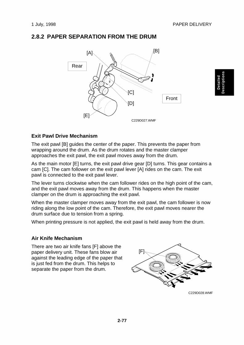
1 July, 1998 PAPER DELIVERY
2-77
Det
aile
dD
escr
ipti
ons
2.8.2 PAPER SEPARATION FROM THE DRUM
Exit Pawl Drive Mechanism
The exit pawl [B] guides the center of the paper. This prevents the paper fromwrapping around the drum. As the drum rotates and the master clamperapproaches the exit pawl, the exit pawl moves away from the drum.
As the main motor [E] turns, the exit pawl drive gear [D] turns. This gear contains acam [C]. The cam follower on the exit pawl lever [A] rides on the cam. The exitpawl is connected to the exit pawl lever.
The lever turns clockwise when the cam follower rides on the high point of the cam,and the exit pawl moves away from the drum. This happens when the masterclamper on the drum is approaching the exit pawl.
When the master clamper moves away from the exit pawl, the cam follower is nowriding along the low point of the cam. Therefore, the exit pawl moves nearer thedrum surface due to tension from a spring.
When printing pressure is not applied, the exit pawl is held away from the drum.
Air Knife Mechanism
There are two air knife fans [F] above thepaper delivery unit. These fans blow airagainst the leading edge of the paper thatis just fed from the drum. This helps toseparate the paper from the drum.
C229D027.WMF
C229D028.WMF
[A] [B]
[C]
[D]
[E]
[F]
Rear
Front

PAPER DELIVERY 1 July, 1998
2-78
2.8.3 PAPER DELIVERY WING MECHANISM
The paper guide wings [A] lift the side of the paper as it leaves the delivery unit.
This stiffens the paper so that the leading edge of the paper will not sag and brushagainst the sheets on the delivery table. This prevents the ink on freshly printedsheets from being smeared.
The angle of the paper wing guides can be changed automatically by the wingguide motor [D], depending on the paper type selected by the operator at theoperation panel. When the paper type is changed, the motor automatically changesthe angle of the wing guides.NOTE: The paper types that can be selected are standard, thick, and special. Two
additional settings for paper types can be customized as user 1 and user 2.The angle of the paper guide wings for each paper type can be adjustedwith SP mode (SP6-100). In addition, the angle can be fixed for all papertypes at the upper or lower position with SP2-120, to override the SP6-100setting. (Refer to the SP mode table in the Service Tables section.)
The wing guide motor [D] moves the paper wing guides up or down through somegears. The wing lower position sensor [C] and wing upper position sensor [B]detect the high and low angle positions of the paper wing guides.
C229D030.WMF
[B]
[C]
[D]
[A]
Rear
Front

1 July, 1998 PAPER DELIVERY
2-79
Det
aile
dD
escr
ipti
ons
2.8.4 PAPER DELIVERY TABLE MECHANISM
The paper delivery table consists of the rear side fence, front side fence, and endfence. The angle of the small paper guide [A] on each side fence can be changedby turning the knob [B].
The small guides help to stack the paper more evenly on the table. Both edges ofthe paper are guided by the guides as the copy is fed out. Then, the paper israpidly fed out against the end plate for stacking.
The front side fence [C] can be laid down towards the operation side, to take outthe paper stack more easily.
When larger paper than A4 is stacked, the end fence must be slid out to the left. Byholding the left end of the table and lifting it up slightly [D], the bottom left of thetable can be slid out.
C229D031.WMF
C229D032.WMF
[A]
[B]
[C]
[D]

PAPER DELIVERY 1 July, 1998
2-80
2.8.5 PAPER DELIVERY JAM SENSORS
Paper Delivery Jam
The exit sensor [A] detects paper jams.
Paper Lower Wrapping
The lower wrapping jam sensor [B] detects when paper is wrapped around thepressure cylinder.
C229D034.WMF
C229D035.WMF
[A]
[B]
Rear
Rear
Front
Front

1 July, 1998 PAPER DELIVERY
2-81
Det
aile
dD
escr
ipti
ons
2.8.6 PAPER DELIVERY UNIT DRIVE MECHANISM
The paper delivery unit is driven by the main motor. As the main motor [D] turns,the main drive timing belt [C] turns. Drive is transmitted to the pulley [B] at the endof the rubber belt drive roller shaft, through the gears and the timing belt.
The knob [A] can be used to rotate the main motor drive manually. A small platenormally covers the knob, and it is not accessible for the operator. It is foremergency use only.
When the knob is turned by hand, it turns the rubber belt drive roller shaft. Therotation is transmitted to the main drive timing belt [C] via the route opposite to thenormal main motor drive.
At the same time as the knob is turned, the drive position indicator disk [F] turnsthrough the shaft [E] and two timing belts. The arrow mark on the disk shows theposition of the main motor drive.
If the operator rotates the pressure cylinder by hand while removing the drum, themain motor drive also turns. It may not be possible to reinstall the drum, becausethe position of the drum drive gear will have changed.
If this happens, the knob can be used to turn the main motor drive. When the arrowon the indicator disk meets the center division, the drive is in the home position.The drum drive gear also in the home position, and the drum can be reset.
C229D023.WMF
[A]
[B] [C]
[D]
[E]
[F]
Rear
Front

PAPER DELIVERY 1 July, 1998
2-82
2.8.7 JOB SEPARATION MECHANISM
Overview
The job separation function can be selected using the Job Separator key on theoperation panel. The print on the top of each print set on the paper delivery table ispulled out slightly by the sliding arm [A]. This function is used normally when two ormore pages were set in the ADF or when in the Class mode.
When a job (a set of copies of one original) is completed, the job separator motor[B] turns on to move the sliding arm [A] onto the paper stack on the paper deliverytable. Then, the slider lift motor [C] lowers the sliding arm.
A high friction material (a type of sandpaper) is attached to the edge of the slidingarm and it touches the top sheet of the paper stack. Then, the job separator motorturns on again to return the sliding arm. Only the top sheet is moved, and it ismoved by about 25 mm.
The sliding arm stays in the same position till the first print of the next job is fed outto the paper delivery table. Then, the job separator and slider lift motors return thesliding arm to the home position.
The slider lift motor can move the sliding arm up and down through a range ofapproximately 60 mm. This means that the job separation function can work withup to approximately 600 sheets of paper (for 64 g/m2 paper) on the paper deliverytable.
C229D033.WMF
[A][B]
[C]

1 July, 1998 PAPER DELIVERY
2-83
Det
aile
dD
escr
ipti
ons
Sliding Arm Control
The sliding arm moves across until the slider position sensor [B] (a micro-switch)tuns on. When the sliding arm returns, the job separation motor turns until theslider HP sensor [C] (a micro-switch) turns on.
While the sliding arm is being lowered onto the top sheet of the paper stack, thepaper sensor [D] (a micro-switch) turns on when the edge of the sliding armtouches the paper.
The slider upper limit sensor [A] detects when the sliding arm is at its highestpossible position.
C229D049.WMF
[A]
[B]
[C]
[D]

IMAGE UP/DOWN SHIFTING 1 July, 1998
2-84
2.9 IMAGE UP/DOWN SHIFTING
2.9.1 OVERVIEW
In Image Up/Down Shifting mode, which can be operated at the operation panel,the image position on the print can be moved forward or backward with respect tothe paper feed direction.
The image shift amount is controlled by changing the registration motor starttiming. However, when the paper feed timing from the registration roller changes,the pressure cylinder position must also be changed so that the paper will becaught properly by the paper clamper on the pressure cylinder. This is alsonecessary to make sure that the printing pressure application area is correct, sincethe pressure cylinder cross-section is not completely circular.
The image up/down shifting mechanism changes the position of the pressurecylinder to match the amount of shift selected.
The mechanism is located in the drum drive gear [A]. It is composed of the imageshift gear [B], image shift motor [E], image shift HP sensor [D], and image shift arm[C]. The HP sensor is activated when the image shifting arm is at home position.
C229D036.WMF
[A]
[B]
[C]
[D]
[E]

1 July, 1998 IMAGE UP/DOWN SHIFTING
2-85
Det
aile
dD
escr
ipti
ons
2.9.2 IMAGE UP/DOWN SHIFTING MECHANISM
This section explains how the machine changes the position of the pressurecylinder to cope with the changed registration start timing in image shifting mode.
The image shift motor [F] turns by an amount that depends on the image shiftamount selected at the operation panel. The motor drives the image shift arm [D]through the worm gear [E].
The image shift arm pivots about the shaft [H]. The image shift gear [C], attachedto the image shift arm, also rotates about the shaft as it moves around the surfaceof the primary gear [A]. The image shift gear turns the primary gear as it movesaround its surface.
The primary gear is connected to the idler pulley [G] via a timing belt. The idlerpulley rotates the pressure cylinder drive gear (not shown). Therefore, moving theimage shift gear up or down rotates the pressure cylinder drive gear, whichchanges the position of the pressure cylinder.
The drum drive gear [B] is also on the shaft [H]. However, it does not turn when theprimary gear turns. Therefore, the drum stays in the same position (the homeposition) even though the position of the pressure cylinder changes.
In this way, a phase difference is made between the positions of the drum andpressure cylinder.
C229D037.WMF
[A][B]
[C]
[D]
[E]
[F]
[G]
[H]

IMAGE UP/DOWN SHIFTING 1 July, 1998
2-86
Shifting Amount Detection
The image shift encoder [A] is activated by the rotation of the pulse disk on theimage shift motor [B]. As the motor turns, this encoder generates a pulse signal.The CPU uses this to detect the amount of motor rotation.
The detected amount is displayed on the operation panel as the image shiftamount.
When the image shifting mode is canceled, the image shift motor turns until theimage shift HP sensor turns on: i.e. the shifting amount is 0.
C229D038.WMF
[A]
[B]

1 July, 1998 ERROR DETECTION
2-87
Det
aile
dD
escr
ipti
ons
2.10 ERROR DETECTION
2.10.1 ORIGINAL FEED ERROR DETECTION IN THE ADF
Registration Sensor
DF Feed Motor
DF Feed Clutch
Image Scanning Start
L+80 mm
Feed-in
Original Feed-in JamThe sensor is still off 5 secondsafter the motor turns on.
Original Feed-out JamThe sensor stays on.
Feed-out
"L" means the original's length.

ERROR DETECTION 1 July, 1998
2-88
2.10.2 MASTER EJECT ERROR DETECTION
Error of Master Pick-up from Drum
1st Drum PositionSensor2nd Drum PositionSensor1st Drum MasterSensor
Master Eject Sensor
Master Eject and Compression Error
HP Sensor
Limit Position Sensor
Pressure Plate Motor
Master Eject Start Timing
Master Eject JamThe master eject sensor doesnot turn on during this period.
Eject Process(Stays ON)
(Stays OFF)
Master Eject Sensor stays on⇒ JamStill off after 8 seconds ⇒ Jam
Drum Master Box Direction Drum Direction
HP EjectPosition
Compressing Position(Stays for 2 seconds)
Returned to HP
Does notreachhere after6 seconds⇒ Motorlocked
Check during rotation in themaster box direction
- Check Timing -When one of the following occurs:
• When Limit Position Sensorturns on.
• 6 seconds passes aftermotor turns on. (4 secondsfor the small sized master.)
Number of HP Sensor On or Off Edges(First on edge is just after motor starts.)
• 5 times ⇒ Normal• 4 times ⇒ Master box full
• Less than 4 ⇒ Pressure plate locked(SC06-00 lights)

1 July, 1998 ERROR DETECTION
2-89
Det
aile
dD
escr
ipti
ons
2.10.3 ERROR DETECTION DURING MASTER MAKING
Master Set and Feed Error
Master Making Unit SetSensor
Master Set Sensor
Master End Sensor
Master Edge SensorPlaten Release Sensor
Platen Release Motor
Master Feed Motor
Duct Entrance Solenoid
Master Feed Clutch
1st CheckThe master edge sensor stays offwhen 5 seconds has passed:⇒ Master Feed Jam
1 s
Master Set Error Detection• The master end sensor is on• The master set sensor stays off
30 mm
2nd CheckThe master edge sensorstays off:⇒ Master Feed Jam
18 mm500 ms
The unit has been set.
The motor turns off when 3seconds has passed and theplaten release sensor turns off.

ERROR DETECTION 1 July, 1998
2-90
Master Cut Error
1st Drum PositionSensor2nd Drum PositionSensor
Master EdgeSensorCutter HP Sensor
Main Motor
Cutter Motor
Error During Clamping the Master to the Drum
2nd Drum PositionSensor2nd Drum MasterSensor
The drum is at the clamping position.
66 degrees
Master Clamping ErrorThe 2nd drum master sensor stays off.
At this time, the status of the master edge sensor is checked.If the sensor remains activated, it means that a master cut errorhas occurred and the following recovery operation is carried out.
Checking the status of the master edge sensor:• OFF: The master cut error has been
recovered, but a master feed jam isdisplayed.
• ON: SC04-20 is displayed (no recovery).
Master Cut for Recovery
This chart is based onthe case that a mastercut error has occurred.
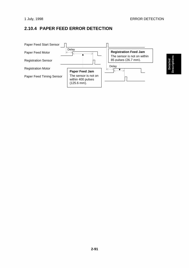
1 July, 1998 ERROR DETECTION
2-91
Det
aile
dD
escr
ipti
ons
2.10.4 PAPER FEED ERROR DETECTION
Paper Feed Start Sensor
Paper Feed Motor
Registration Sensor
Registration Motor
Paper Feed Timing Sensor
Delay
Paper Feed JamThe sensor is not onwithin 400 pulses(125.6 mm).
Delay
Registration Feed JamThe sensor is not on within85 pulses (26.7 mm).

ERROR DETECTION 1 July, 1998
2-92
2.10.5 PAPER DELIVERY ERROR DETECTION
Paper Delivery Error
1st Drum PositionSensor
Paper Exit Sensor
Paper Upper/Lower Wrapping Detection
Paper Feed StartSensorPaper Exit Sensor
Lower WrappingJam Sensor
The sensor status check when the feed start sensor turns on.• The paper exit sensor is off, and the lower wrapping jam
sensor remains off⇒ Paper jam wrapped around the drum
• Lower wrapping jam sensor is on:⇒ Paper jam wrapped around the pressure cylinder
132° 7°
1st Check 2nd Check
Paper Exit JamAt both 1st and 2nd checks, theexit sensor is not on.

1 July, 1998 INSTALLATION REQUIREMENTS
3-1
Inst
alla
tion
3. INSTALLATION
3.1 INSTALLATION REQUIREMENTS
The installation location should be carefully chosen because the environmentalconditions greatly affect the performance of the machine.
3.1.1 REQUIRED ENVIRONMENTAL CONDITIONS
1. Temperature 10 to 30°C (50 to 86°F)
2. Humidity 20 to 90 % RH
3. Place the machine on a strong and level base. The machine must be levelwithin 5 mm both front to rear and left to right.
3.1.2 ENVIRONMENTS TO AVOID
1. Locations exposed to direct sunlight or strong light (more than 1,500 lux).
2. Areas with corrosive gases.
3. Dusty areas.
4. Locations directly exposed to cool air from an air conditioner or reflected heatfrom a space heater. (Sudden temperature changes from low to high or viceversa may cause condensation within the machine.)
3.1.3 POWER CONNECTION
1. Securely connect the power cord to a power source.
2. Make sure that the wall outlet is near the machine and easily accessible.
3. Make sure the plug is firmly inserted in the outlet.
4. Avoid multiwiring.
5. Voltage must not fluctuate more than 10%.
6. Do not pinch the power cord.

INSTALLATION REQUIREMENTS 1 July, 1998
3-2
3.1.4 ACCESS TO MACHINE:
Place the machine near a power source, providing clearance, as shown below.
C231I510.WMF
More than 10 cm (4.0")
65 cm(25.6")
More than60 cm(23.7”)
More than60 cm
(23.7”)
141 cm (55.6")More than60 cm
(23.7”)
PaperDeliveryTable
PaperFeedTable

1 July, 1998 INSTALLATION PROCEDURE
3-3
Inst
alla
tion
3.2 INSTALLATION PROCEDURE
3.2.1 MAIN BODY
Accessory Check
Make sure that you have all the accessories listed below.
Operating Instructions (Expect for Ricoh European Version) .............. 1NECR (Ricoh version only).................................................................. 1Brand Stickers (OEM version only) ........................................................................... 1 setModel Name Plates (OEM version only) .......................................................................... 1 set
Paper Delivery Table ........................................................................... 1 set
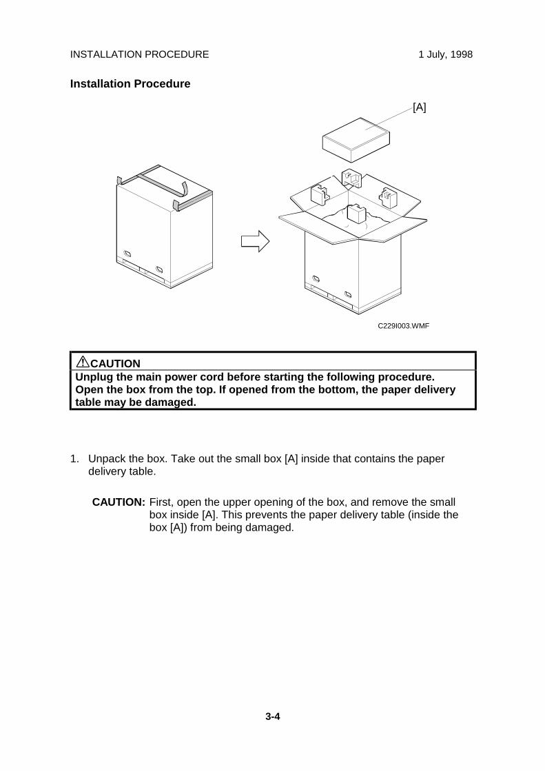
INSTALLATION PROCEDURE 1 July, 1998
3-4
Installation Procedure
CAUTIONUnplug the main power cord before starting the following procedure.Open the box from the top. If opened from the bottom, the paper deliverytable may be damaged.
1. Unpack the box. Take out the small box [A] inside that contains the paperdelivery table.
CAUTION: First, open the upper opening of the box, and remove the smallbox inside [A]. This prevents the paper delivery table (inside thebox [A]) from being damaged.
C229I003.WMF
[A]

1 July, 1998 INSTALLATION PROCEDURE
3-5
Inst
alla
tion
2. Continue to unpack the box. Make sure that there are the accessory bag [A]and the paper delivery unit inside the small box [B].
C229I010.WMF
C229I002.WMF
[B]
[A]

INSTALLATION PROCEDURE 1 July, 1998
3-6
3. When installing the optional table, mount the machine, as shown. (2 screwspacked with the table).
CAUTIONOnly handle using the carrying handles [A] on the bottom of the machine.Otherwise, your fingers may be pinched between the main body and thetable during installation. (The gap between the bottom of the main bodyand the table is very small.)
C229I006.WMF
[A]

1 July, 1998 INSTALLATION PROCEDURE
3-7
Inst
alla
tion
4. Remove the tape securing the covers and units, and the master clamperprotective sheet [A], as shown.
C229I004.WMF
C229I011.WMF
[A]

INSTALLATION PROCEDURE 1 July, 1998
3-8
5. Take out the paper delivery table from the box.
6. Set the front and rear side fences, as shown.
7. Assemble the paper delivery table, as shown (two screws).
C229I008.WMF
C229I009.WMF

1 July, 1998 INSTALLATION PROCEDURE
3-9
Inst
alla
tion
8. Install the paper delivery table (2 screws).
9. Install the master roll.
10. Install the ink cartridge.
11. Firmly insert the plug in the wall outlet.
CAUTION: Make sure that the wall outlet is near the machine and easilyaccessible.
12. Turn on the main switch.
13. Press the “Economy Mode” key while holding down the “0” key, to supply ink tothe drum.
14. Make test copies.
C229I007.WMF

INSTALLATION PROCEDURE 1 July, 1998
3-10
3.2.2 AUTO DOCUMENT FEEDER (OPTION)
Accessory Check
Make sure that you have all the accessories listed below.
Document feeder unit ..............................................................1
DF harness ..............................................................................1
Screws ....................................................................................2
Thumb screws ........................................................................4
Stabilizer brackets ..................................................................2
DF scale cover ........................................................................1
DF exposure glass ..................................................................1
Caution label ...........................................................................1

1 July, 1998 INSTALLATION PROCEDURE
3-11
Inst
alla
tion
Installation Procedure
CAUTIONUnplug the main body power cord before starting the following procedure.
Moving the MPU aside
1. First, remove the rear exterior cover of the main body.
A: Remove the memory board [A] (If installed as this is an option).
B: Disconnect the flat cable [B].
NOTE: Gently pull out the lever [C] to release the flat cable, as shown. It caneasily be damaged. Also, when reconnecting it, carefully push it backas shown [D].
2. Remove 7 screws securing the MPU bracket to flip over the MPU.
C229R032.WMF
[A]
[B][C] [D]

INSTALLATION PROCEDURE 1 July, 1998
3-12
ADF harness installation
1. Remove the rear cover (6 screws) and the DF connector cover (2 screws).
2. Swing out the MPU bracket [A] (6 screws).
3. Run the DF harness (accessory), as shown, and fasten it with the clamps [B] (5clamps), which were originally used in the main body.
4. Connect the cable connector [C] to CN216 on the I/O board.
5. Attach the connector [D] at the opposite end to the connector bracket (2screws).
A628O031.WMF
[A]
[C]
[D]
[B]

1 July, 1998 INSTALLATION PROCEDURE
3-13
Inst
alla
tion
ADF stabilizer installation
1. Attach the two stabilizer brackets [A] to the back of the table using thethumbscrews [B] (4 screws). All components are in the accessories.
2. Attach the caution label [C], as shown.
CAUTIONThis procedure must be done to prevent the machine from fallingbackwards when the ADF is open.
C229I500.WMF
[A]
[C]
[A][B]

INSTALLATION PROCEDURE 1 July, 1998
3-14
CAUTIONUnplug the main body power cord before starting the following procedure.When installing the DF, use the DF tool [A] or a standard screwdriver.
ADF installation
1. Unplug the document feeder. Then, remove the shipping tape.
2. Remove the left scale [B] (2 screws).
3. Place the DF exposure glass [C] on the glass holder.
4. Peel off the backing [D] of the double side tape attached to the rear side of thescale guide [E], then install the scale guide (2 screws).
5. Attach the original size decal [F] to the scale guide.NOTE: Place the decal at the rear edge, and the left side flush with the scale
paper guide [E], as shown.
6. Install the stud screws [G].
A628I502.WMF
A628I501.WMF
A628I500.WMF
[B]
[C]
[D]
[F]
[E]
[G
[A]

1 July, 1998 INSTALLATION PROCEDURE
3-15
Inst
alla
tion
7. Install the DF unit [A].
8. Slide the DF to the left, then secure the DF unit with the 2 screws (M4×10).
9. Connect the I/F harness [B] to the main body.
10. Attach the original direction decals [C] to the DF table, as shown.
11. Turn the main switch on. Then, check if the document feeder works properly.
A628O032.WMF
A628I505.WMF
[A]
[B]
[C]

INSTALLATION PROCEDURE 1 July, 1998
3-16
3.2.3 INTERFACE BOARD (OPTION)
NOTE: The interface board is originally installed in the U.S.A and Europeanversion models as a standard part, not an option.
1. Remove the rear cover and the right rear cover.
2. Install the I/F board [A] in CN102 on the MPU (2 screws).
3. Connect the cable [B] (accessory) to the I/F board.
4. Attach the connector [C] at the opposite end to the connector bracket (2screws).
5. Cut away the blindfold cover [D] on the right rear cover.
A628O033.WMF
A628O034.WMF
[A]
[B]
[C]
[D]

1 July, 1998 INSTALLATION PROCEDURE
3-17
Inst
alla
tion
3.2.4 COLOR DRUM (OPTION)
There are two types of color drum units:
Color Drum – A3 Drum
Color Drum – A4 Drum
1. Take the color drum out of the drum case. Remove the holder [A].
2. Remove the protective paper in the master clamper.
3. Attach the appropriate color decal (accessory) [B] to the drum case.
4. Remove the original drum, as shown.
5. Install the color drum in the machine.
C229I011.WMF
C229I026.WMF
C229I017.WMFC229I027.WMF
[B]
[A]

1 July, 1998 SERVICE REMARKS
4-1
Ser
vice
Tab
les
4. SERVICE TABLES
4.1 SERVICE REMARKS
4.1.1 SCANNER SECTION
1. Xenon Lamp
Do not touch the xenon lamp while it is on, or you might receive a weak electricalshock.
2. Scanner Wire Installation
A special tool is needed. See “6.5.7 Scanner Wire.”
3. Sensor Board Unit (SBU) Calibration
When the MPU is replaced or the standard white plate located behind the originalscale is replaced, the SBU must be calibrated with SP6-32-1.
4.1.2 MASTER EJECT SECTION
1. Master Pick-up Roller Drive Gear and Master Clamper Drive ArmPositions
These parts must be positioned correctly. See "6.6.4 Reassembling the MasterPick-up Roller Drive Gears."
4.1.3 MASTER FEED SECTION
1. Thermal Head 1When installing the thermal head, there are important points to note. See "Remarksfor Handling the Thermal Head" in "2.2.7 Thermal Head."
2. Thermal Head 2
When replacing the thermal head, be sure to adjust the voltage supplied to thethermal head (See “6.7.6 Thermal Head Voltage Adjustment”).

SERVICE REMARKS 1 July, 1998
4-2
3. Master Vacuum Fan Position
The fan must be positioned correctly. See "6.7.5 Master Vacuum Fan Positioning."
4. Master Feed Mylar Positions
When replacing or removing the thermal head, the cutter unit, the master duct, orthe guide plate of the lower master feed control roller, the strips of mylar are easilyput in the wrong position while installing the lower tension roller or lower masterfeed control roller. For details, refer to "6.7.10 Master Feed Mylar Positioning."
4.1.4 PAPER FEED SECTION
1. Paper Feed Roller and Paper Separation Roller 1
Be careful to install the rollers the correct way around. They have a one-way clutchinside.
2. Paper Feed Roller and Paper Separation Roller 2
Do not touch the surfaces of the rollers with bare hands.
4.1.5 DRUM AND DRUM DRIVE SECTION
1. Doctor Roller
Normally the doctor roller gap is not adjusted or changed. It tends to be difficult toadjust in the field. If the gap becomes narrower, an uneven image may appear onthe prints. If it becomes wider, too much ink will be applied to the drum screens,resulting in ink leakage from the drum.
2. Drum Master Clamper1) Do not allow the inside of the clamping plate to become dirty with ink.2) Do not use alcohol or other solvents to clean the inside of the clamping plate.
Use a cloth dampened with water.
3. Ink Roller Unit
Do not disassemble the ink roller unit. Each part between the front and rear sideplates of this unit has been precisely adjusted on the production line to keep thedoctor and ink rollers parallel against the drum shaft.

1 July, 1998 SERVICE REMARKS
4-3
Ser
vice
Tab
les
4.1.6 MAIN DRIVE SECTION
1. Main Drive Adjustment
Special tools are needed for the adjustment. For details, see "6.11.2 Main DriveMechanism (Main Timing Belt)."
4.1.7 ELECTRICAL COMPONENTS
1. Main Processing Unit (MPU) and I/O Board
After replacing the MPU or I/O board, some adjustments are needed. See "6.3MPU and I/O Board Replacement."
2. Main Processing Unit (MPU) and Power Supply Unit
To access the rear of the machine, the MPU and I/O board have to be moved outof the way. See "6.4 MPU and PSU Opening Procedures."
3. Power Supply Unit
When replacing the power supply unit, be sure to adjust the voltage supplied to thethermal head. See “6.7.6 Thermal Head Voltage Adjustment.”
4. Program Update
To update the software in the flash ROM on the MPU, a special tool is needed. See“4.5.4 Load Program (SP8-20).”
5. Sensor Adjustments
Adjustment is needed for the following sensors
1st drum master sensor2nd drum master sensorMaster eject sensorMaster edge sensorMaster end sensor
For details, see the adjustment procedures for each sensor in section 6.
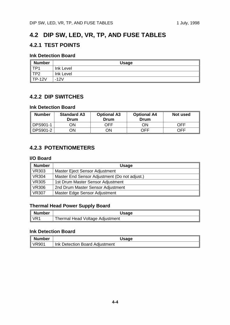
DIP SW, LED, VR, TP, AND FUSE TABLES 1 July, 1998
4-4
4.2 DIP SW, LED, VR, TP, AND FUSE TABLES
4.2.1 TEST POINTS
Ink Detection BoardNumber Usage
TP1 Ink LevelTP2 Ink LevelTP-12V -12V
4.2.2 DIP SWITCHES
Ink Detection BoardNumber Standard A3
DrumOptional A3
DrumOptional A4
DrumNot used
DPS901-1 ON OFF ON OFFDPS901-2 ON ON OFF OFF
4.2.3 POTENTIOMETERS
I/O BoardNumber Usage
VR303 Master Eject Sensor AdjustmentVR304 Master End Sensor Adjustment (Do not adjust.)VR305 1st Drum Master Sensor AdjustmentVR306 2nd Drum Master Sensor AdjustmentVR307 Master Edge Sensor Adjustment
Thermal Head Power Supply BoardNumber Usage
VR1 Thermal Head Voltage Adjustment
Ink Detection BoardNumber Usage
VR901 Ink Detection Board Adjustment

1 July, 1998 DIP SW, LED, VR, TP, AND FUSE TABLES
4-5
Ser
vice
Tab
les
4.2.4 LED'S
MPUNumber Function
LED101 Monitors the CPU operation. Usually, this LED is blinking.LED102 Monitors power supplied to the MPU. Usually, this LED is lit.
I/O BoardNumber Function
LED300 Not used.LED301 Not used.LED302 Monitors the Master Eject Sensor.LED303 Monitors the Master Edge Sensor.LED304 Monitors the feed control CPU operation. Usually, this LED is blinking.LED305 Monitors power supplied to the I/O board. Usually, this LED is lit.
4.2.5 FUSES
Power Supply UnitFuse Rated Current Protect
FU700 10A Power Supply UnitFU701 5A Main Motor Drive BoardFU702 5A Main Motor Drive BoardFU703 5A I/O BoardFU704 5A Thermal Head Power Supply Board, I/O Board
Thermal Head Power Supply BoardFuse Rated Current Protect
FU750 2A Thermal Head
Main Motor Control BoardFuse Rated Current Protect
FUSE 10A Main Motor

SERVICE CALL CODES 1 July, 1998
4-6
4.3 SERVICE CALL CODES
Code Title Conditions Possible CausesSC02-00 Scanner motor
lock (the HPsensor remainsoff)
After the scanner has left homeposition, it does not return therefor more than 7 seconds.
• Defective scanner HPsensor
• Scanner wire slip-off• Defective scanner
motorSC02-01 Scanner motor
lock (the HPsensor remainson)
At power on or when the Startkey is pressed, the scanner doesnot move from the home positiontowards the scanning direction formore than 2 seconds.
• Defective scanner HPsensor
• Scanner wire slip-off• Defective scanner
motorSC02-02 Scanner motor
lock (the scannerdoes not return toHP)
At power on, the scanner doesnot return to the home positionwithin 2 seconds after it left.
• Defective scanner HPsensor
• Scanner wire slip-off• Defective scanner
motorSC03-00 Thermal head ID
errorThe CPU detects an abnormal IDsignal from the thermal head.
• Defective thermal head• Defective MPU
SC03-01 Thermal headenergy pulseerror
The CPU detects an abnormalthermal head energy controlpulse.
• Defective MPU• Defective PSU
SC03-02 Thermal headthermistor short
The signal from the thermal headthermistor reaches 4.88 volts.
• Thermistor open circuit• Related connector
disconnectedSC03-03 Thermal head
temperatureabnormal
When the Start key is pressed, atemperature of 54 °C or more isdetected at the thermal head.
• Thermistor short• Defective thermal head
SC04-00 Cutter HP sensorremains on
The cutter does not leave thehome for more than 3 secondsafter the cutter motor on signal isgenerated.
• Defective sensor• Defective motor• Jammed master
SC04-01 Cutter HP sensorremains off
The cutter does not return to thehome for more than 3 secondsafter the cutter has left home
• Defective sensor• Defective motor• Jammed master
SC04-10 Platen releasesensor remainson
The sensor is not de-activated formore than 5 seconds after theplaten release motor on signal isgenerated.
• Defective sensor• Defective motor
SC04-11 Platen releasesensor remainsoff
The sensor is not activated formore than 5 seconds after theplaten release motor on signal isgenerated.
• Defective sensor• Defective motor

1 July, 1998 SERVICE CALL CODES
4-7
Ser
vice
Tab
les
Code Title Conditions Possible CausesSC04-20 Master cut error If the master edge sensor
remains on even after the firstmaster cut recovery operation.(Normally, the master is cut if themaster edge sensor detects amis-cut master the first time.)
• Defective master edgesensor
• Defective cutter unit• Defective master
vacuum fans• Jammed master
SC05-00 Main motor lock(1st drumposition sensordoes not turn on)
At power on or when the drumreturns to home position, the 1stdrum position sensor is notactivated for more than 3.75seconds after the main motor onsignal is generated.
• Defective sensor• Defective main motor
SC05-01 Main motor lock(motor controlsignal error)
The CPU on the motor controlboard detects an abnormal signalfrom the main motor encoder.
• Defective main motor
SC05-10 Image shift HPsensor remainson
At power on, the sensor is not de-activated for more than 25seconds after the image shiftmotor on signal is generated.
• Defective sensor• Defective motor
SC05-11 Image shift HPsensor remainsoff
At power on, the sensor is notactivated for more than 25seconds after the image shiftmotor on signal is generated.
• Defective sensor• Defective motor
SC05-12 No imageposition encoderpulse
At power on or when the imageup/down shift mode is selected,the CPU detects no encoderpulse from the sensor for morethan 25 seconds after the imageshift motor on signal isgenerated.
• Defective sensor
SC05-20 Drum shift HPsensor remainson
At power on, the sensor is not de-activated for more than 6seconds after the drum shiftmotor on signal is generated.
• Defective sensor• Defective motor
SC05-21 Drum shift HPsensor remainsoff
At power on, the sensor is notactivated for more than 6seconds after the drum shiftmotor on signal is generated.
• Defective sensor• Defective motor
SC05-22 No drum shiftsensor pulse
At power on or when the imageside-to-side shift mode isselected, the CPU detects noencoder pulse from the sensor formore than 6 seconds after thedrum shift motor on signal isgenerated.
• Defective sensor
SC05-30 Drum thermistoropen
The signal from the thermistorbeside the ink detecting pinsreaches 4.5 volts.
• Thermistor open circuit• Related connector
disconnected

SERVICE CALL CODES 1 July, 1998
4-8
Code Title Conditions Possible CausesSC05-31 Drum thermistor
shortThe thermistor beside the inkdetecting pins detects anexcessively high temperature (96°C).
• Thermistor short
SC05-32 Ink pump sensorremains on
The sensor is not de-activatedafter the ink pump motor onsignal is generated.
• Defective sensor• Defective motor• Jammed ink pump
driveSC05-33 Ink pump sensor
remains offThe sensor is not activated afterthe ink pump motor on signal isgenerated.
• Defective sensor• Defective motor• Jammed ink pump
driveSC05-40 A4 cam sensor
remains onThe sensor does not de-activatefor more than 6 seconds after thepressure cam shift motor onsignal is generated.
• Defective sensor• Defective motor
SC05-41 A3 cam sensorremains off
The sensor does not activate formore than 6 seconds after thepressure cam shift motor onsignal is generated.
• Defective sensor• Defective motor
SC05-42 A3 cam sensorremains on
The sensor does not de-activatefor more than 6 seconds after thepressure cam shift motor onsignal is generated.
• Defective sensor• Defective motor
SC05-43 A4 cam sensorremains off
The sensor does not activate formore than 6 seconds after thepressure cam shift motor onsignal is generated.
• Defective sensor• Defective motor
SC05-50 Clamper closeposition sensorremains on whenopening theclamper
At the master clamper opentiming, the sensor is not de-activated for more than 4seconds after the clamper motoron signal is generated.
• Defective sensor• Defective motor• Jammed drum guide
drive• Defective 2nd drum
position sensorSC05-51 Clamper open
position sensorremains off whenopening theclamper
At the master clamper opentiming, the sensor is not activatedfor more than 4 seconds after theclamper motor on signal isgenerated.
• Defective sensor• Defective motor• Jammed drum guide
drive• Defective 2nd drum
position sensorSC05-52 Clamper open
position sensorremains on whenopening theclamper
At the master clamper opentiming, the sensor is not de-activated for more than 4seconds after the clamper motoron signal is generated.
• Defective sensor• Defective motor• Jammed drum guide
drive• Defective 2nd drum
position sensor

1 July, 1998 SERVICE CALL CODES
4-9
Ser
vice
Tab
les
Code Title Conditions Possible CausesSC05-53 Clamper open
position sensorremains off whenclosing theclamper
At the master clamper closingtiming, the sensor is not activatedfor more than 4 seconds after theclamper motor on signal isgenerated.
• Defective sensor• Defective motor• Jammed drum guide
drive• Defective 2nd drum
position sensorSC05-54 Clamper open
position sensorremains on whenclosing theclamper
At the master clamper closingtiming, the sensor is not de-activated for more than 4seconds after the clamper motoron signal is generated.
• Defective sensor• Defective motor• Jammed drum guide
drive• Defective 2nd drum
position sensorSC05-55 Clamper close
position sensorremains off whenclosing theclamper
At the master clamper closingtiming, the sensor is not activatedfor more than 4 seconds after theclamper motor on signal isgenerated.
• Defective sensor• Defective motor• Jammed drum guide
drive• Defective 2nd drum
position sensorSC05-60 Idling HP sensor
remains onThe sensor does not de-activateafter the idling roller motor onsignal is generated.
• Defective sensor• Defective motor
SC05-61 Idling HP sensorremains off
The sensor does not activateafter the idling roller motor onsignal is generated.
• Defective sensor• Defective motor
SC06-00 Pressure platedoes not movefrom home to themaster ejectready position
The pressure plate does notreach the master eject readyposition after it has left home formore than 3 seconds after thepressure plate motor on signal isgenerated.
• Defective sensor• Defective motor• Jammed master
SC06-01 Pressure platedoes not return tothe homeposition
The pressure plate does notreach the home position for morethan 6 seconds after the pressureplate motor on signal isgenerated.
• Defective sensor• Defective motor• Jammed master
SC06-02 Pressure platedoes not move tothe compressionposition
The pressure plate does notreach home while traveling fromthe master eject ready position tocompression position for morethan 6 seconds after the pressureplate motor on signal isgenerated.
• Defective sensor• Defective motor• Jammed master
SC07-00 Sensor 0 in thefeed pressuredetection boardremains on
The sensor does not changestatus.
• Defective feedpressure detectionboard
• Defective feedpressure motor

SERVICE CALL CODES 1 July, 1998
4-10
Code Title Conditions Possible CausesSC07-01 Sensor 0 in the
feed pressuredetection boardremains off
The sensor does not changestatus.
• Defective feedpressure detectionboard
• Defective feedpressure motor
SC07-02 Sensor 1 in thefeed pressuredetection boardremains on
The sensor does not changestatus.
• Defective feedpressure detectionboard
• Defective feedpressure motor
SC07-03 Sensor 1 in thefeed pressuredetection boardremains off
The sensor does not changestatus.
• Defective feedpressure detectionboard
• Defective feedpressure motor
SC07-04 Sensor 2 in thefeed pressuredetection boardremains on
The sensor does not changestatus.
• Defective feedpressure detectionboard
• Defective feedpressure motor
SC07-05 Sensor 2 in thefeed pressuredetection boardremains off
The sensor does not changestatus.
• Defective feedpressure detectionboard
• Defective feedpressure motor
SC07-06 Sensor 3 in thefeed pressuredetection boardremains on
The sensor does not changestatus.
• Defective feedpressure detectionboard
• Defective feedpressure motor
SC07-07 Sensor 3 in thefeed pressuredetection boardremains off
The sensor does not changestatus.
• Defective feedpressure detectionboard
• Defective feedpressure motor
SC07-10 Sensor 0 in theseparationpressuredetection boardremains on
The sensor does not changestatus.
• Defective separationpressure detectionboard
• Defective separationpressure motor
SC07-11 Sensor 0 in theseparationpressuredetection boardremains off
The sensor does not changestatus.
• Defective separationpressure detectionboard
• Defective separationpressure motor

1 July, 1998 SERVICE CALL CODES
4-11
Ser
vice
Tab
les
Code Title Conditions Possible CausesSC07-12 Sensor 1 in the
separationpressuredetection boardremains on
The sensor does not changestatus.
• Defective separationpressure detectionboard
• Defective separationpressure motor
SC07-13 Sensor 1 in theseparationpressuredetection boardremains off
The sensor does not changestatus.
• Defective separationpressure detectionboard
• Defective separationpressure motor
SC07-14 Sensor 2 in theseparationpressuredetection boardremains on
The sensor does not changestatus.
• Defective separationpressure detectionboard
• Defective separationpressure motor
SC07-15 Sensor 2 in theseparationpressuredetection boardremains off
The sensor does not changestatus.
• Defective separationpressure detectionboard
• Defective separationpressure motor
SC07-16 Sensor 3 in theseparationpressuredetection boardremains on
The sensor does not changestatus.
• Defective separationpressure detectionboard
• Defective separationpressure motor
SC07-17 Sensor 3 in theseparationpressuredetection boardremains off
The sensor does not changestatus.
• Defective separationpressure detectionboard
• Defective separationpressure motor
SC07-20 Feed encodererror
The CPU detects an abnormalsignal from the feed encoder.
• Defective I/O board• Defective sensor
SC07-50 Wing lowerposition sensorremains on
At the wing guide movingupwards timing, the sensor is notde-activated for more than 6seconds after the wing guidemotor on signal is generated.
• Defective sensor• Defective motor
SC07-51 Wing upperposition sensorremains off
At the wing guide movingupwards timing, the sensor is notactivated for more than 6seconds after the wing guidemotor on signal is generated.
• Defective sensor• Defective motor
SC07-52 Wing upperposition sensorremains on
At the wing guide movingdownwards timing, the sensor isnot de-activated for more than 6seconds after the wing guidemotor on signal is generated.
• Defective sensor• Defective motor

SERVICE CALL CODES 1 July, 1998
4-12
Code Title Conditions Possible CausesSC07-53 Wing lower
position sensorremains off
At the wing guide movingdownwards timing, the sensor isnot activated for more than 6seconds after the wing guidemotor on signal is generated.
• Defective sensor• Defective motor
SC07-60 Paper sensor (inthe job separator)remains on
At the slider moving upwardstiming, the sensor is not de-activated for more than 9seconds after the slider lift motoron signal is generated.
• Defective sensor• Defective motor• Defective job separator
board
SC07-61 Slider upper limitsensor remainsoff
At the slider moving upwardstiming, the sensor is not activatedfor more than 9 seconds after theslider lift motor on signal isgenerated.
• Defective sensor• Defective motor• Defective job separator
board
SC07-62 Slider upper limitsensor remainson
At the slider moving downwardstiming, the sensor is not de-activated for more than 9seconds after the slider lift motoron signal is generated.
• Defective sensor• Defective motor• Defective job separator
board
SC07-63 Paper sensor (injob separator)remains off
At the slider moving downwardstiming, the sensor is not activatedfor more than 9 seconds after theslider lift motor on signal isgenerated.
• Defective sensor• Defective motor• Defective job separator
board
SC07-70 Slider HP sensorremains on
At the slider moving toward thedelivery table timing, the sensoris not de-activated for more than6 seconds after the job separatormotor on signal is generated.
• Defective sensor• Defective motor• Defective job separator
board
SC07-72 Slider positionsensor remainson when sliderreturns
At the slider returning timing, thesensor is not de-activated formore than 6 seconds after the jobseparator motor on signal isgenerated.
• Defective sensor• Defective motor• Defective job separator
board
SC07-73 Slider HP sensorremains off whenslider returns
At the slider returning timing, thesensor is not activated for morethan 6 seconds after the jobseparator motor on signal isgenerated.
• Defective sensor• Defective motor• Defective job separator
board
SC30-00 Paper table lowerlimit sensorremains on
At the table moving upwardstiming, the sensor is not de-activated for more than 7.5seconds after the paper tablemotor on signal is generated.
• Defective sensor• Defective motor
SC30-01 Paper heightsensor remainsoff
At the table moving upwardstiming, the sensor is not activatedfor more than 7.5 seconds afterthe paper table motor on signal isgenerated.
• Defective sensor• Defective motor

1 July, 1998 SERVICE CALL CODES
4-13
Ser
vice
Tab
les
Code Title Conditions Possible CausesSC30-02 Paper height
sensor remainson
At the table moving downwardstiming, the sensor is not de-activated for more than 7.5seconds after the paper tablemotor on signal is generated.
• Defective sensor• Defective motor
SC30-03 Paper table lowerlimit sensorremains off
At the table moving downwardstiming, the sensor is not activatedfor more than 7.5 seconds afterthe paper table motor on signal isgenerated.
• Defective sensor• Defective motor
SC80-00 PC controllerinterface signalerror
Signal transmission error in theinterface board.
• Defective interfaceboard

SPECIAL TOOLS 1 July, 1998
4-14
4.4 SPECIAL TOOLS
The following are the special tools used for service.
Description Part Number ApplicationMain Drive Securing Tool Kit(Drum securing tool and twopositioning shafts as a set)
C229 9000 For main drive positioning(See 6.11.2 Main DriveMechanism section)
ROM Board - 2 A193 9351 For program download(See 4.5.4 Load Programsection)
Scanner Positioning Pin Kit(4 pins as a set)
A006 9104 For scanner wireinstallation(See 6.5.7 Scanner Wiresection)
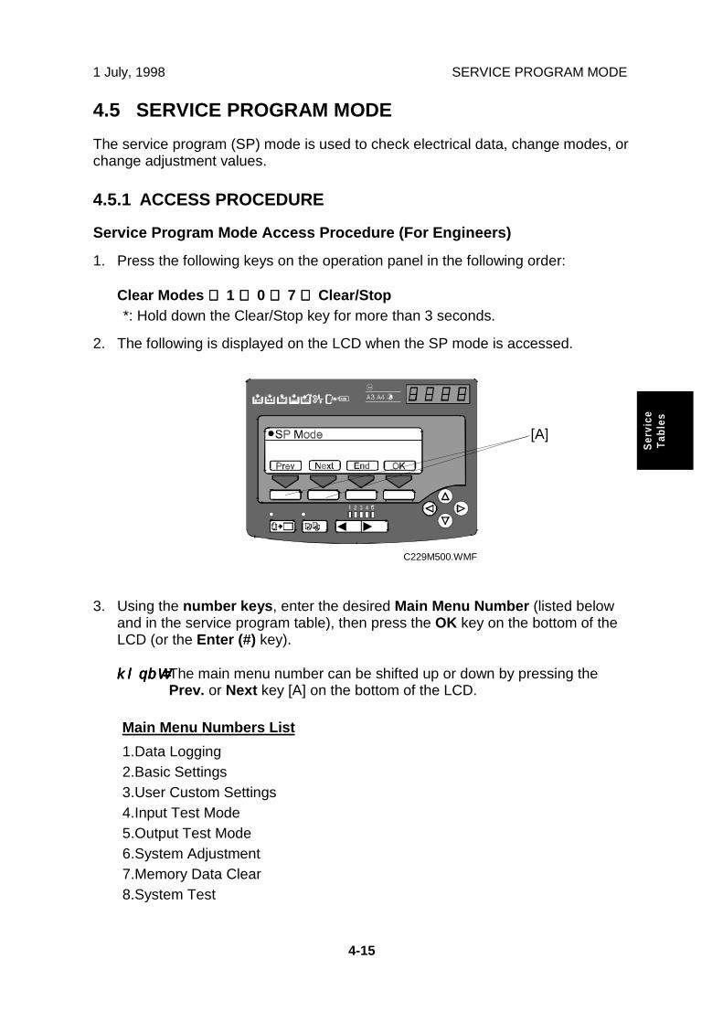
1 July, 1998 SERVICE PROGRAM MODE
4-15
Ser
vice
Tab
les
4.5 SERVICE PROGRAM MODE
The service program (SP) mode is used to check electrical data, change modes, orchange adjustment values.
4.5.1 ACCESS PROCEDURE
Service Program Mode Access Procedure (For Engineers)
1. Press the following keys on the operation panel in the following order:
Clear Modes ⇒⇒⇒⇒ 1 ⇒⇒⇒⇒ 0 ⇒⇒⇒⇒ 7 ⇒⇒⇒⇒ Clear/Stop *: Hold down the Clear/Stop key for more than 3 seconds.
2. The following is displayed on the LCD when the SP mode is accessed.
3. Using the number keys, enter the desired Main Menu Number (listed belowand in the service program table), then press the OK key on the bottom of theLCD (or the Enter (#) key).
klqbW=klqbW=klqbW=klqbW= The main menu number can be shifted up or down by pressing thePrev. or Next key [A] on the bottom of the LCD.
Main Menu Numbers List
1.Data Logging2.Basic Settings3.User Custom Settings4.Input Test Mode5.Output Test Mode6.System Adjustment7.Memory Data Clear8.System Test
C229M500.WMF
[A]

SERVICE PROGRAM MODE 1 July, 1998
4-16
4. Using the number keys, enter the desired Sub Menu Number (listed in theservice program table), then press the OK key on the bottom of the LCD (or theEnter (#) key).
klqbW=klqbW=klqbW=klqbW= The sub menu number can be shifted up or down by pressing the Prev.or Next key [A] on the bottom of the LCD.
5. Not for all sub menu items but for some, there are menus under the sub menu.Using the Prev. or Next key [A] on the bottom of the LCD, select the desiredmenu.
klqbW=klqbW=klqbW=klqbW= These menus are not accessible by entering the number with thenumber keys.
6. Follow the "Change Adjustment Values or Modes" procedure below.
klqbW=klqbW=klqbW=klqbW= To cancel the SP mode, press the Clear Modes key or the Return (orEnd) key on the bottom of the LCD.
Change Adjustment Values or Modes
1. After entering the desired SP mode, pressing the OK key on the bottom of theLCD (or the Enter (#) key). The current value or mode will be displayed on theLCD (at the end of the second line).
2. Enter the desired value or mode using the number keys (listed in the serviceprogram table).
klqbW=klqbW=klqbW=klqbW= Use the key to toggle between + and -.
3. Press the OK key to store the desired value or mode.
4. To cancel the SP mode, press the Clear Modes key or the Return (or End)key on the bottom of the LCD.

1 July, 1998 1. DATA LOGGING
4-17
Ser
vice
Tab
les
4.5.2 SERVICE PROGRAM TABLE
Main Menu Number List
1.Data Logging2.Basic Settings3.User Custom Settings4.Input Test Mode5.Output Test Mode6.System Adjustment7.Memory Data Clear8.System Test
1. Data Logging
SP No. Display Function Default UserTools
1-001-1 Total Master Counter 0 - 1-001-2 Resettable Master Count 0 1-2 1-001-3 M Counter ADF Mode 0 - 1-001-4 M Counter Economy Mode 0 - 1-001-5 M Counter Combine 2 0 - 1-001-6 M Counter Combine 4 0 - 1-001-7 M Counter Enl. Mode 0 - 1-001-8 M Counter Red. Mode 0 - 1-001-9 M Counter Zoom Mode 0 - 1-001-10 M Counter Dir. Mag. 0 - 1-001-11 M Counter Make-up Mode 0 - 1-001-12 M Counter Make-up Photo 0 - 1-001-13 M Counter Margin Erase 0 - 1-001-14 M Counter Online Mode 0 - 1-001-15 M Counter Online Overlay 0 - 1-001-16 M Counter Overlay Mode 0 - 1-001-17 M Counter Format Overlay 0 -
1-001-18 M Counter MemoryCombine
0 -
1-001-19 M Counter Date Stamp 0 - 1-001-20 M Counter Page Number 0 - 1-001-21 M Counter Default Stamp 0 - 1-001-22 M Counter User Stamp 0 - 1-001-23 M Counter Letter Mode 0 - 1-001-24 M Counter Ltr/Pht Mode 0 - 1-001-25 M Counter Photo Mode 0 - 1-001-26 M Counter Pencil Mode 0 - 1-001-27 M Counter Tint Mode
Master counters
1-001-1: Total count1-001-2: User counter1-001-3 to 27: Counters forvarious copy modes
0 -

1. DATA LOGGING 1 July, 1998
4-18
SP No. Display Function Default UserTools
1-001-28 M Counter A3/DLT 0 - 1-001-29 M Counter B4/LG 0 - 1-001-30 M Counter A4-L/LT-L 0 - 1-001-31 M Counter A4/LT 0 - 1-001-32 M Counter B5-L 0 - 1-001-33 M Counter B5 0 - 1-001-34 M Counter Other Sizes 0 - 1-001-35 M Counter Up/Down Sift 0 - 1-001-36 M Counter Side Shift 0 - 1-001-37 M Counter Short Master 0 - 1-001-38 M Counter Image Rotation 0 - 1-001-39 M Counter Special 0 - 1-001-40 M Count Standard Paper 0 - 1-001-41 M Counter Thick Paper 0 - 1-001-42 M Counter User 1 Paper 0 - 1-001-43 M Counter User 2 Paper 0 - 1-001-44 M Counter Same-No. Class 0 - 1-001-45 M Counter By-Class Class 0 - 1-001-46 M Counter Manual Class 0 - 1-001-47 M Counter Job Separator 0 - 1-001-48 M Counter Autocycle
Master counters
1-001-28 to 34: Originalsizes1-001-35, 36, 44 to 48:Various copy modes1-001-39 to 43: Varioustypes
0 - 1-002-1 Total Print Counter 0 - 1-002-2 Resettable Print Counter 0 1-2 1-002-3 P Counter Color Drum 0 - 1-002-4 P Counter Over A3/DLT 0 - 1-002-5 Print Counter A3/DLT 0 - 1-002-6 Print Counter B4/LG 0 - 1-002-7 Print Counter A4-L/LT-L 0 - 1-002-8 Print Counter A4/LT 0 - 1-002-9 Print Counter B5-L 0 - 1-002-10 Print Counter B5 0 - 1-002-11 Print Counter A6-L 0 - 1-002-12 Print Counter Under A6-L 0 - 1-002-13 P Counter Other Sizes
Print counters
‘-L’: Lengthwise
0 - 1-003 Set Master Counter 0 - 1-004 Ejected Master Counter 0 - 1-005 Ink Pump Rotation Count 0 - 1-006 Master End Counter 0 - 1-007 Ink End Counter 0 - 1-008 Master Full Counter 0 - 1-020 Original Counter ADF 0 - 1-021 Original Counter Platen 0 - 1-030-1 UC M Counter: Code 1 0 - 1-030-2 UC P Counter: Code 1
Master and printer countersfor each user code 0 -

1 July, 1998 1. DATA LOGGING
4-19
Ser
vice
Tab
les
SP No. Display Function Default UserTools
1-030-3 UC M Counter: Code 2 0 - 1-030-4 UC P Counter: Code 2 0 - 1-030-5 UC M Counter: Code 3 0 - 1-030-6 UC P Counter: Code 3 0 - 1-030-7 UC M Counter: Code 4 0 - 1-030-8 UC P Counter: Code 4 0 - 1-030-9 UC M Counter: Code 5 0 - 1-030-10 UC P Counter: Code 5 0 - 1-030-11 UC M Counter: Code 6 0 - 1-030-12 UC P Counter: Code 6 0 - 1-030-13 UC M Counter: Code 7 0 - 1-030-14 UC P Counter: Code 7 0 - 1-030-15 UC M Counter: Code 8 0 - 1-030-16 UC P Counter: Code 8 0 - 1-030-17 UC M Counter: Code 9 0 - 1-030-18 UC P Counter: Code 9 0 - 1-030-19 UC M Counter: Code10 0 - 1-030-20 UC P Counter: Code10 0 - 1-030-21 UC M Counter: Code11 0 - 1-030-22 UC P Counter: Code11 0 - 1-030-23 UC M Counter: Code12 0 - 1-030-24 UC P Counter: Code12 0 - 1-030-25 UC M Counter: Code13 0 - 1-030-26 UC P Counter: Code13 0 - 1-030-27 UC M Counter: Code14 0 - 1-030-28 UC P Counter: Code14 0 - 1-030-29 UC M Counter: Code15 0 - 1-030-30 UC P Counter: Code15 0 - 1-030-31 UC M Counter: Code16 0 - 1-030-32 UC P Counter: Code16 0 - 1-030-33 UC M Counter: Code17 0 - 1-030-34 UC P Counter: Code17 0 - 1-030-35 UC M Counter: Code18 0 - 1-030-36 UC P Counter: Code18 0 - 1-030-37 UC M Counter: Code19 0 - 1-030-38 UC P Counter: Code19 0 - 1-030-39 UC M Counter: Code20 0 - 1-030-40 UC P Counter: Code20 0 - 1-031-1 UC Total Master Counter 0 - 1-031-2 UC Total Print Counter
Master and printer countersfor each user code
0 - 1-040 ROM Part Number - -
1-041 Machine Serial NumberEnter data with SP3-70 atinstallation if required. - -
1-042 ROM Version - -

1. DATA LOGGING 1 July, 1998
4-20
SP No. Display Function Default UserTools
1-050 Service Telephone NumberEnter data with SP3-72 atinstallation if required. 0 -
1-051 Last Service Call Code 0 - 1-060 Power On Time 0 - 1-070-1 1 - 5 Prints 0 - 1-070-2 6 - 10 Prints 0 - 1-070-3 11 - 20 Prints 0 - 1-070-4 21 - 30 Prints 0 - 1-070-5 31 - 50 Prints 0 - 1-070-6 51 - 70 Prints 0 - 1-070-7 71 - 100 Prints 0 - 1-070-8 101 - 200 Prints 0 - 1-070-9 201 - 500 Prints 0 - 1-070-10 501 - 1000 Prints 0 - 1-070-11 Over 1000 Prints
Copies-per-originalcounters
0 - 1-080 Misfeed Setting Counter 0 -
1-081 Multifeed Setting Count
Number of times the userchanged the ‘Misfeed’ or‘Multifeed’ settings forpaper feed or separationpressures
0 -
1-082 Start Error Message Cnt.Number of times an errormessage appeared whenthe Start key was pressed
0 -
1-102-1 Jam DF Feed-in Error 0 - 1-102-2 Jam DF Feedout Error 0 - 1-104-1 Jam Master Set Error 0 - 1-104-2 Jam Master Clamp Error 0 - 1-104-3 Jam Master Cut Error 0 - 1-106-1 Jam Master Eject ON Chk 0 - 1-106-2 Jam Pressure Plate Error 0 - 1-106-3 Jam Master Eject OFF Chk 0 - 1-107-1 Jam Regist ON Check 0 -
1-107-2 Jam Feed Timing ONCheck
0 -
1-107-3 Jam Feed Timing OFF Chk 0 - 1-107-4 Jam Paper Upper Wrapping 0 - 1-107-5 Jam Paper Lower Wrapping 0 - 1-107-6 Jam Paper Exit OFF Check
Counters for various typesof jams
0 -
1-202-1 Jam% DF Feed-in ErrorJam ratio for various typesof jam 0 -
1-202-2 Jam% DF Feed-out Error 0 - 1-204-1 Jam% Master Set Error 0 - 1-204-2 Jam% Master Clamp Error 0 - 1-204-3 Jam% Master Cut Error 0 - 1-206-1 Jam% Master Eject ON Chk 0 - 1-206-2 Jam% Press Plate Error 0 -

1 July, 1998 1. DATA LOGGING
4-21
Ser
vice
Tab
les
SP No. Display Function Default UserTools
1-206-3 Jam% M Eject OFF Check 0 - 1-207-1 Jam% Regist ON Check 0 - 1-207-2 Jam% Feed Timing ON Chk 0 -
1-207-3 Jam% Feed Timing OFFChk
0 -
1-207-4 Jam% Paper Upper Wrap 0 - 1-207-5 Jam% Paper Lower Wrap 0 - 1-207-6 Jam% Paper Exit OFF Chk
Jam ratio for various typesof jam
0 - 1-300-1 Jam P0 A3/B4 Standard 0 - 1-300-2 Jam P0 A3/B4 Thick 0 - 1-300-3 Jam P0 A3/B4 Others 0 - 1-300-4 Jam P0 A4/B5-L Standard 0 - 1-300-5 Jam P0 A4/B5-L Thick 0 - 1-300-6 Jam P0 A4/B5-L Others 0 - 1-300-7 Jam P0 A4/B5 Standard 0 - 1-300-8 Jam P0 A4/B5 Thick 0 - 1-300-9 Jam P0 A4/B5 Others 0 - 1-300-10 Jam P0 Other Sizes Std 0 - 1-300-11 Jam P0 Other Sizes Thick 0 - 1-300-12 JamP0 Other Sizes Others
Feed-in jams andregistration roller jams forvarious paper sizes andpaper types
‘-L’: Lengthwise
0 - 1-301-1 Jam P1 A3/B4 Standard 0 - 1-301-2 Jam P1 A3/B4 Thick 0 - 1-301-3 Jam P1 A3/B4 Others 0 - 1-301-4 Jam P1 A4/B5-L Standard 0 - 1-301-5 Jam P1 A4/B5-L Thick 0 - 1-301-6 Jam P1 A4/B5-L Others 0 - 1-301-7 Jam P1 A4/B5 Standard 0 - 1-301-8 Jam P1 A4/B5 Thick 0 - 1-301-9 Jam P1 A4/B5 Others 0 - 1-301-10 Jam P1 Other Sizes Std 0 - 1-301-11 Jam P1 Other Sizes Thick 0 - 1-301-12 JamP1 Other Sizes Others
Registration roller jams (Incase if the paper feedtiming sensor stays on) forvarious paper sizes andpaper types
‘-L’: Lengthwise
0 - 1-302-1 Jam P2 A3/B4 Standard 0 - 1-302-2 Jam P2 A3/B4 Thick 0 - 1-302-3 Jam P2 A3/B4 Others 0 - 1-302-4 Jam P2 A4/B5-L Standard 0 - 1-302-5 Jam P2 A4/B5-L Thick 0 - 1-302-6 Jam P2 A4/B5L Others 0 - 1-302-7 Jam P2 A4/B5 Standard
Upper wrap, lower wrap,and feed-out jams forvarious paper sizes andpaper types
‘-L’: Lengthwise
0 - 1-302-8 Jam P2 A4/B5 Thick 0 - 1-302-9 Jam P2 A4/B5 Others 0 - 1-302-10 Jam P2 Other Sizes Std 0 - 1-302-11 Jam P2 Other Sizes Thick 0 -
1-302-12 Jam P2 Other Sizes Others 0 -

1. DATA LOGGING 1 July, 1998
4-22
SP No. Display Function Default UserTools
1-303-1 P Count A3/B4 Standard 0 - 1-303-2 P Count A3/B4 Thick 0 - 1-303-3 P Count A3/B4 Others 0 - 1-303-4 P Count A4/B5-L Standard 0 - 1-303-5 P Count A4/B5-L Thick 0 - 1-303-6 P Count A4/B5L Others 0 - 1-303-7 P Counter A4/B5 Standard 0 - 1-303-8 P Count A4/B5 Thick 0 - 1-303-9 P Count A4/B5 Others 0 - 1-303-10 P Count Other Sizes Std
Print counters for variouspaper sizes and paper
types
0 - 1-303-11 P Count Other Sizes Thk 0 - 1-303-12 P Cnt Other Sizes Others 0 - 1-304-1 M Set Error Low Temp 0 - 1-304-2 M Set Error Normal Temp 0 - 1-304-3 M Set Error High Temp 0 - 1-305-1 M Clamp Error Low Temp 0 - 1-305-2 M Clamp Error Nor. Temp 0 - 1-305-3 M Clamp Error High Temp 0 - 1-306-1 M Cut Error Low Temp 0 - 1-306-2 M Cut Error Normal Temp 0 - 1-306-3 M Cut Error High Temp 0 - 1-307-1 M Eject ON Jam Low Temp 0 - 1-307-2 M Eject ON Jam Nor Temp 0 - 1-307-3 M Eject ON Jam High Temp 0 - 1-308-1 Press Plate Error Low 0 - 1-308-2 Press Plate Error Normal 0 - 1-308-3 Press Plate Error High 0 -
1-309-1 M Eject OFF Jam LowTemp
Master error counters fordifferent temperature
conditions (temperaturedetected by the thermistor
in the drum)
0 -
1-309-2 M Eject OFF Jam Nor Temp 0 - 1-309-3 M Eject OFF Jam High Tem 0 -

1 July, 1998 2. BASIC SETTINGS
4-23
Ser
vice
Tab
les
2. Basic Settings
SP No. Display Function Default Setting UserTools
2-002 Set Key Counter Also see 2-291. No No/Yes - 2-003 Set Key Card Japan only No No/Yes - 2-006 PC Controller Settings Do not adjust. AUTO AUTO /
10PS1-9
2-010 Sizes in Metric or Inch - 0:JPN1:mm2:Inch
1-6
2-011 Select Language Type See Note 1. - 0 to 6 - 2-020-1 Default Original Mode 0 0 to 3 3-3 2-020-2 Default Tint Mode OFF ON/OFF 3-8 2-020-3 Default Paper Type 1 0 to 4 3-1 2-020-4 Default Master Density 1 0 to 3 3-2 2-020-5 Default Print Speed 3 1 to 5 - 2-020-6 Default Auto Cycle Mode ON ON/OFF 4-1 2-020-7 Def Image Position
Tp/Btm0 -15.0 to
15.0-
2-020-8 Def Image Position Lt/Rt 0 -10.0 to10.0
-
2-020-9 Default Photo/Lightness 1 0 to 2 3-6 2-020-10 Default Photo/Screen 0 0 to 4 3-7 2-020-11 Def On-line Paper Size 14 0 to 14 3-10 2-020-12 Default Make-up Pattern1 0 0 to 43 - 2-020-13 Default Make-up Pattern2 0 0 to 43 - 2-020-14 Default Make-up Pattern3 0 0 to 43 - 2-020-15 Default Make-up Pattern4
Defaults forvarious usersettingsSee Notes 2 to 9.
0 0 to 43 - 2-030 Panel Beeper See Note 10. 1 0 to 2 2-5 2-031 Background Correction See Note 11. No No/Yes 4-6 2-032-1 TH Egy Temp Ctl - Black ON ON/OFF - 2-032-2 TH Egy Temp Ctl - Color
See Note 12OFF ON/OFF
2-040 Ink Detection ON ON/OFF - 2-041 Paper Length Detection ON ON/OFF - 2-042-1 Paper Width Detection ON ON/OFF 4-3 2-042-2 Paper Size Indicators OFF ON/OFF - 2-043 Drum Master Detection ON ON/OFF - 2-044 Platen Cover Set Detect ON ON/OFF - 2-045 ADF Close Detection ON ON/OFF - 2-046-1 Platen Orig. Size Detect ON ON/OFF 4-5 2-046-2 ADF Orig. Size Detect
Enables/disablesvarious sensors fortest purposes
2-042-2: OFFmeans that theindicators are on.
2-046-2: See Note13. ON ON/OFF 4-4
2-060 Long Paper Mode See Note 14. OFF ON/OFF - 2-070 Auto Combine Originals See Note 15. NO YES/NO 4-8 2-080 A3 Master 2 Count Up See Note 16. 0 0 to 2 - 2-090 APS A5 Size Detection See Note 17. NO YES/NO - 2-100 User Code Mode OFF ON/OFF 1-4

2. BASIC SETTINGS 1 July, 1998
4-24
SP No. Display Function Default Setting UserTools
2-110 Auto Quality Start ON ON/OFF 4-13 2-120 Exit Wing Position See Note 18. 0 0 to 2 4-15 2-150 Auto Image Rotation See Note 19. Yes Yes/No 4-20 2-170 Auto Master Save Select OFF: A3 master
always usedregardless oforiginal size.
AUTO AUTO /OFF
4-21
2-210 Ink Master Left Also for masterroll. See Note 20.
OFF ON/OFF 4-18
2-220 Key Card Setting Japan only 1 0 to 3 1-5 2-230 Copy Count Display Down Up /
Down2-3
2-240 Class Display Select Japan only Normal School/Normal
2-241 Class Entry Per Orig. Normal By Orig /Normal
4-2
2-250 Combine Orig. Sep. Line See Note 21. 0 0 to 4 4-9 2-260 Auto Combine Mode
ResetNo Yes/No 4-10
2-270 Print Restart in Class See Note 22. 2 1 to 2 4-16 2-271 Job Sep. At Class Mode Yes Yes/No 4-17 2-290 Key Operator Code OFF ON/OFF 6-6 2-291 Restricted Access See Note 23. OFF ON/OFF 6-8 2-300 Stamp Type See Note 24. 0 0 to 6 5-1 2-301 Default Stamp Size See Note 25. 0 0 to 3 5-2 2-302 Default Stamp Density See Note 26. 0 0 to 2 5-3 2-303 Default Stamp Position See Note 27. 0 0 to 9 5-4 2-304 User Stamp Size 0 0 to 3 5-5 2-305 User Stamp Density 0 0 to 2 5-6 2-306 User Stamp Position
See Note 28.
0 0 to 9 5-7 2-307 Date Stamp Type m.d.’y d.m.’y /
m.d.’y5-9
2-308 Date Stamp Position See Note 29. 0 0 to 3 5-10 2-309 Page Numbering Type See Note 30. 0 0 to 2 5-12 2-310 Default Page Position See Note 31. 0 0 to 3 5-13 2-320 Skip Feed Mode Display Yes Yes/No 4-11 2-370 Ink Supply w/Trial Print ON: Ink is supplied
while a trial print ismade after makinga new master.
OFF ON/OFF -
2-380 Japanese Display Type Do not use. 0 0 to 2 - 2-390 A3/DLT Drum Selection See Note 32. - DLT/A3 - 2-400 User1 Paper Type 0 0 to 5 4-19 2-401 User2 Paper Type
See Note 33.0 0 to 5 4-19

1 July, 1998 2. BASIC SETTINGS
4-25
Ser
vice
Tab
les
SP No. Display Function Default Setting UserTools
2-410 Auto On-line Mode YES: The on-linemode isautomaticallyactivated whendata is sent from aPC (needs theoptional PCcontroller)
No Yes/No -
2-420 Feed Friction Pad Type Do not use. Normal Normal /Custom
-
2-421 Type of Thermal Head Do not use. 2 1 to 2 -
Notes
1: 2-011 (Display language)
0: Japanese, 1: English, 2: German, 3: French, 4: Italian, 5: Spanish, 6: Dutch,7: Chinese
2: 2-020-1 (Default original mode)
0: Letter, 1: Letter/Photo, 2: Photo, 3: Pencil
3: 2-020-3 (Default paper type)
0: Special, 1: Standard, 2: Thick, 3: User 1, 4: User 2
4: 2-020-4 (Default master density)
0: Pale, 1: Normal, 2: Fairly dark, 3: Dark
5: 2-020-5 (Default print speed, cpm)
1: 60, 2: 75, 3: 90, 4: 105, 5: 120
6: 2-020-9 (Default Photo/Lightness)
This is the default brightness in photo or letter/photo mode.
0: Dark, 1: Normal, 2: Light
7: 2-020-10 (Default Photo/Screen)
This is the default screen type for photo mode.
0: Standard, 1: Coarse 1, 2: Coarse 2, 3: Coarse 3, 4: Coarse 4 (coarsest)

2. BASIC SETTINGS 1 July, 1998
4-26
8: 2-020-11 (Default On Line paper size)
This is the default paper size when the On Line key is pressed,
0: A3, 1: B4, 2: A4, 3: A4 lengthwise, 4: B5, 5: B5 lengthwise, 6: A5,7: A5 lengthwise, 8: A6, 9: A6 lengthwise, 10 to 12: Not used, 13: Free, 14: Auto
Free – The master size is determined by the paper size sent from the PC.
Auto – The master size is determined by the paper size on the paper feed table. Ifthe data from the PC is for a larger paper size, the excess data is lost.
Other settings: For example, if the setting is 0 (A3), the machine always makes anA3 master.
9: 2-020-12 to -15 (Default make-up patterns 1 to 4)
0 to 39: Preset patterns, from 1 to 4040 to 43: User-created patterns A to D
10: 2-030 (Panel beeper)
0: Disabled, 1: Enabled (except for when keys pressed), 2: Enabled fully
11: 2-031 (Background correction)
This can be used in letter/photo, photo, and tint modes to prevent the backgroundof an original from appearing on copies. See Detailed Section Descriptions –Image Processing for more details.
12: 2-032 (Thermal head energy control with temperature)
If this is switched on, the energy supplied to the thermal head will depend on thetemperature measured by the thermistor in the drum.
Less than 25 °C 25 – 30 °C More than 30 °C
Standard SP 3-020-1 value(Default: -7%)
SP 3-020-1 – 5%(Default: -12%)
SP 3-020-1 – 10%(Default: -17%)
Economy SP 3-020-2 value (Default: -25%)
13: 2-046-2 (ADF original size detection)
Disabling ADF original size detection allows the ADF to scan originals within thefollowing range.
Width: 105 to 297 mmLength: 128 to 864 mm
14: 2-060 (Long paper mode)
This disables trailing edge detection to allow long printer paper to be fed. This isnot within specifications, so the machine’s performance cannot be guaranteedusing this mode.

1 July, 1998 2. BASIC SETTINGS
4-27
Ser
vice
Tab
les
15: 2-070 (Auto Combine Original mode)
This SP mode determines the use of the Combine key.
0: Normal – The Combine key accesses the Combine feature, in which twooriginals can be combined onto one copy
1: Automatic – The Combine key accesses the Auto Combine feature, in which thesame original is printed twice or four times on the copy
This SP mode is only referred to when using the exposure glass. From the ADF,Auto Combine is always used if more than one original is placed.
The default is Normal.
16: 2-080 (Double count-up for A3 masters)
0: The counters go up by 1 only.
1: The master counter goes up by 2.
2: The master and print counters both go up by 2.
17: 2-090 (APS A5 Size Detection)
This determines how the machine behaves if the APS sensors cannot detect theoriginal because it is too small
0: No original detected, 1: A5 assumed
Default: 0
18: 2-120 (Exit Wing Position)
This determines the position of the wings on the paper delivery table.
0: Auto (determined by the setting of SP6-100 for the currently-used paper type)
1: Always Up (regardless of SP6-100), 2: Always Down (regardless of SP6-100)
19: 2-150 (Auto Image Rotation)
If enabled, this feature rotates the scanned image if the original and printing paperare of the same size but different orientations.
0: Disabled, 1: Enabled
Default: Enabled

2. BASIC SETTINGS 1 July, 1998
4-28
20: 2-210 (Ink Near-end Detection)
This SP mode enables and disables the display for ink and master roll near-enddetection.
The machine determines how much of the master roll is remaining by subtractingthe length of each master that is made.
In addition, it determines how much ink is left by counting the number of ink pumpstrokes that have been made.
The default is 0 (disabled). In this condition, the master and ink consumption is stillmonitored, but if a near-end condition occurs, it will not be displayed.
If this SP mode is changed to 1 (enabled), near-end will be displayed, but only for afew seconds when the machine has just been switched on.
21: 2-250 (Separation lines for Combine Original mode)
This can only be used with Memory Combine mode, using the optional memoryboard.
This determines the type of separation line printed on copies between the imagesof the different originals.
0: None (default), 1: Solid, 2: Broken line type A, 3: Broken line type B, 4: Cropmarks
22: 2-270 (Print Restart in Class)
This determines how the machine behaves if the Job Separator feature is not used.
1: Auto Start – After printing for one class has been finished, there is a pause of afew seconds, then printing for the next class begins automatically. The short breakallows the user to take the stack of prints off the delivery table.
2: Disabled (Default) – After printing for one class has been finished, the machinestops. The user must press Print to start printing for the next class.
23: 2-291 (Restricted Access)
When the key counter is installed, the technician enables the key counter with SP2-002. However, the user can override this setting with SP 2-291 (which is alsouser tool 6-8).
OFF: Copies can be made even if the user has no key counter, regardless of SP 2-002.
ON: The user must have a key counter, if SP2-002 has been switched on.
The default is OFF, so to use the key counter, the user must switch 2-291 on usingthe equivalent user tool (6-8).
24: 2-300 (Stamp type)
This determines what the Stamping function (Stamp key) puts on the printouts.

1 July, 1998 2. BASIC SETTINGS
4-29
Ser
vice
Tab
les
25: 2-301 (Default stamp size)
This determines the size of the stamp.
0: Normal (about 32 x 64 mm), 1: x 2, 2: x 4, 3: x 8
26: 2-302 (Default Stamp Density)
0: Solid fill (default), 1: Fine pattern, 2: Coarse pattern
27: 2-303 (Default Stamp Position)
0: Upper left, 1: Upper middle, 2: Upper right, 3: Center left, 4: Center,5: Center right, 6: Lower left, 7: Lower middle, 8: Lower right,9: Everywhere (repeated)
User tool 5-4 (SP 3-120 to 128) can be used to adjust the co-ordinates of types 0to 8.
28: 2-304 to 2-306 (User Stamp Size, Density, and Position)
These settings are the same as SP 2-301 to 2-303, except that they are for theuser stamp. User stamps are stored using user tool 5-8.
User tool 5-7 (SP 3-130 to 138) can be used to adjust the co-ordinates of types 0to 8.
29: 2-308 (Date Stamp Position)
0: Upper left (horizontal), 1: Lower right (horizontal), 2: Lower left (vertical),3: Upper right (vertical)
30: 2-309 (Page Numbering Type)
0: P1, P2, P3, . . 1: 1/5, 2/5, 3/5, . . 2: - 1 -, - 2 -, - 3 -, . . .
31: 2-310 (Default Page Number Stamping Position)
0: Upper right (horizontal), 1: Upper left (vertical), 2: Bottom middle (horizontal),3: Center right (vertical)
Settings 0 and 1 determine the default for the ‘P1, P2’ and ‘1/5, 2/5’ types of pagenumbering.
Settings 2 and 3 determine the default for the ‘- 1 -, - 2 -‘ types of page numbering.
32: 2-390 (Drum Size – A3 or DLT)
This setting changes the master making area. It also affects the available range forthe default image position shift (top/bottom, SP2-020-7).
A3: -15 mm to + 15 mmDLT: -10 mm to + 10 mm

2. BASIC SETTINGS 1 July, 1998
4-30
33: 2-400, 401 (Paper types for User 1 and User 2)
The user can customize two paper types (User 1 and User 2) in addition to thethree usual paper types (Normal, Thick, Special).
These SP modes give the machine a rough idea of what type of paper the user isusing as types User 1 and User 2.
0: This paper type is not being used at present1: Standard, no feed (Standard paper type, non feed likely)2: Standard, double feed (Standard paper type, double feed likely)3: Thick, no feed (Thick paper type, non feed likely)4: Thick, double feed (Thick paper type, double feed likely)5: Thick, medium (Thick paper type, with intermediate chances of double and non-feed)

1 July, 1998 3. USER CUSTOM SETTINGS
4-31
Ser
vice
Tab
les
3. User Custom Settings
SP No. Display Function Default Setting UserTools
3-001 Minimum PrintQuantity
0 0 to9999%
2-1
3-002 Maximum PrintQuantity
9999 0 to9999%
2-2
3-010-1 Magnification (A3 toA4)
71 50 to200%
3-4
3-010-2 Magnification (B4 toA4)
82 50 to200%
3-4
3-010-3 Magnification (A3 toB4)
87 50 to200%
3-4
3-010-4 Magnification(Margins)
93 50 to200%
3-4
3-010-5 Magnification(Standard)
100 50 to200%
3-4
3-010-6 Magnification (B4 toA3)
115 50 to200%
3-4
3-010-7 Magnification (A4 toB4)
122 50 to200%
3-4
3-010-8 Magnification (A4toA3)
Allows the user tochange the defaultreproduction ratios
141 50 to200%
3-4
3-020-1 T Head Energy -Standard
-7 0 to -99%
-
3-020-2 T Head Energy -Economy
Thermal head energy instandard and economymodes, as percentage offull power. Also see SP2-032.
-25 0 to -99%
-
3-030 Auto Reset Time Determines how long ittakes for the machine toreturn to the defaults.
0 0, 1 to 5 1-1
3-051 Number of SkipFeeds
2 1-9 4-11
3-060-1 MarginErase A3MainScan
293 50-297 3-9
3-060-2 MarginErase A3SubScan
420 50-420 3-9
3-060-3 MarginErase B4/LG-L Main
253 50-257 3-9
3-060-4 MarginErase B4/LG-L Sub
Determines the edgeerase margins.
For example, for A3main scan, the width ofthe original is 297 mm,and the erase margin isset at 293. This meansthat only the central 293
mm will be scanned. 360 50-364 3-9
3-060-5 MarginErase A4/LT-L Main
206 50-216 3-9
3-060-6 MarginErase A4/LT-L Sub
293 50-297 3-9
3-060-7 MarginErase A4MainScan
293 50-297 3-9
3-060-8 MarginErase A4SubScan
206 50-216 3-9

3. USER CUSTOM SETTINGS 1 July, 1998
4-32
SP No. Display Function Default Setting UserTools
3-060-9 MarginErase B5-LMain
178 50-182 3-9
3-060-10 MarginErase B5-LSub
253 50-257 3-9
3-060-11 MarginErase B5MainScan
253 50-257 3-9
3-060-12 MarginErase B5SubScan
178 50-182 3-9
3-060-13 MarginErase A5-LMain
144 50-148 3-9
3-060-14 MarginErase A5-LSub
Determines the edgeerase margins.For example, for A3main scan, the width ofthe original is 297 mm,and the erase margin isset at 293. This meansthat only the central 293mm will be scanned.
206 50-210 3-9
3-060-15 MarginErase A5MainScan
206 50-210 3-9
3-060-16 MarginErase A5SubScan
144 50-148 3-9
3-060-17 MarginErase Card-LMain
96 50-105 3-9
3-060-18 MarginErase Card-LSub
144 50-148 3-9
3-060-19 MarginErase CardMain
144 50-148 3-9
3-060-20 MarginErase CardSub
96 50-105 3-9
3-060-21 MarginEraseCustom Main
66 50-300 3-9
3-060-22 MarginEraseCustom Sub
161 50-432 3-9
3-061-1 Set Custom Size -Main
70 50-300 3-9
3-061-2 Set Custom Size -Sub
This allows the user toinput a custom size.SP3-060-21 and 22specify edge erasemargins for this originalsize.
165 50-432 3-9
3-070 Machine SerialNumber
0 - -
3-071 Installation Date 0 - - 3-072 Service Telephone
Number0 - -
3-073 Clock - - 1-8 3-074 First Power On Date
Do these at installation ifrequired. The data isused in the data printoutmode in the system test.(SP3-70 and -72 can beseen in SP41 and -50.)
- - - 3-090 Manual Idling
RotationThis determines thenumber of drum idlingrotations when the userhas selected QualityStart with the QualityStart key.
45 0-90 4-12

1 July, 1998 3. USER CUSTOM SETTINGS
4-33
Ser
vice
Tab
les
SP No. Display Function Default Setting UserTools
3-091-1 Auto Idling 0-4h 0 0-90 4-14 3-091-2 Auto Idling 4-24h 0 0-90 4-14 3-091-3 Auto Idling 24-72h 15 0-90 4-14 3-091-4 Auto Idling 72h-Over 15 0-90 4-14 3-092-1 AutoIdling 0-4h Low
Temp0 0-90 4-14
3-092-2 Auto Idling 4-24hLow
15 0-90 4-14
3-092-3 Auto Idling 24-72hLow
45 0-90 4-14
3-092-4 Auto Idling 72h-OverLow
45 0-90 4-14
3-093-1 AutoIdling 0-4hHighTemp
0 0-90 4-14
3-093-2 Auto Idling 4-24hHigh
0 0-90 4-14
3-093-3 Auto Idling 24-72hHigh
0 0-90 4-14
3-093-4 AutoIdling 72h-OverHigh
These determine thenumber of drum idlingrotations in Auto QualityStart mode, dependingon the length of time themachine has beenunused.3-091: 15 to 28 °C3-092: Below 15 °C3-093: Above 28 °C
15 0-90 4-14
3-100(-1 to -12)
Register Class 1-1 to1-12
30 0-9999 3-5
3-101 (-1 to -12)
Register Class 2-1 to2-12
0 0-9999 3-5
3-102 (-1 to -12)
Register Class 3-1 to3-12
0 0-9999 3-5
3-103 (-1 to -12)
Register Class 4-1 to4-12
0 0-9999 3-5
3-104 (-1 to -12)
Register Class 5-1 to5-12
0 0-9999 3-5
3-105 (-1 to -12)
Register Class 6-1 to6-12
0 0-9999 3-5
3-106 (-1 to -12)
Register Class 7-1 to7-12
0 0-9999 3-5
3-107 (-1 to -12)
Register Class 8-1 to8-12
0 0-9999 3-5
3-108 (-1 to -12)
Register Class 9-1 to9-12
The number of studentsin each class.No. of grades: Up to 9No. of classes pergrade: Up to 12No. of students perclass: Program withthese SP modes
Defaults for each gradeClasses 1 to 4: 30Classes 5 to 12: 0
0 0-9999 3-5
3-110 Register User Code - - 6-3 3-111 Change User Code - - 6-4 3-112 Register Key
Operator0000 0000 to
99996-7
3-113 Clear User Code
These are foradministering the usercodes and the keyoperator code.
- - 6-5 3-120-1 Stamp Top Rt - Side 24 8 to 144 5-4 3-120-2 Stamp Top Rt -
UpDown24 8 to 104 5-4
3-121-1 Stamp Top Mdl -Side
These specify the co-ordinates of the eightpossible positions for thepreset stamp. 0 -72 to 72 5-4

3. USER CUSTOM SETTINGS 1 July, 1998
4-34
SP No. Display Function Default Setting UserTools
3-121-2 Stamp Top Mdl -UpDown
24 8 to 104 5-4
3-122-1 Stamp Top Lft - Side 24 8 to 144 5-4 3-122-2 Stamp Top Lft -
UpDown
These specify the co-ordinates of the eightpossible positions for thepreset stamp. 24 8 to 104 5-4
3-123-1 Stamp Btm Rt - Side 24 8 to 144 5-4 3-123-2 Stamp Btm Rt -
UpDown24 8 to 104 5-4
3-124-1 Stamp Btm Mdl -Side
0 -72 to 72 5-4
3-124-2 Stamp Btm Mdl -UpDown
24 8 to 104 5-4
3-125-1 Stamp Btm Lft - Side 24 8 to 144 5-4 3-125-2 Stamp Btm Lft -
UpDown24 8 to 104 5-4
3-126-1 Stamp Rt Mdl - Side 24 8 to 144 5-4 3-126-2 Stamp Rt Mdl -
UpDown0 -52 to 52 5-4
3-127-1 Stamp Center - Side 0 -72 to 72 5-4 3-127-2 Stamp Center -
UpDown0 -52 to 52 5-4
3-128-1 Stamp Lft Mdl - Side 24 8 to 144 5-4 3-128-2 Stamp Lft Mdl -
UpDown0 -52 to 52 5-4
3-130-1 UserStamp Top Rt -Side
24 8 to 144 5-7
3-130-2 UserStamp Top Rt -UpDn
24 8 to 104 5-7
3-131-1 U Stamp Top Mdl -Side
These specify the co-ordinates of the eightpossible positions for theuser stamp.
0 -72 to 72 5-7
3-131-2 U Stamp Top Mdl -UpDown
24 8 to 104 5-7
3-132-1 U Stamp Top Lft -Side
24 8 to 144 5-7
3-132-2 U Stamp Top Lft -UpDown
24 8 to 104 5-7
3-133-1 User Stamp Btm Rt -Side
24 8 to 144 5-7
3-133-2 User Stamp Btm Rt -UpDn
24 8 to 104 5-7
3-134-1 U Stamp Btm Mdl -Side
0 -72 to 72 5-7
3-134-2 U Stamp Btm Mdl -UpDown
24 8 to 104 5-7
3-135-1 U Stamp Btm Lft -Side
24 8 to 144 5-7
3-135-2 U Stamp Btm Lft -UpDown
24 8 to 104 5-7

1 July, 1998 3. USER CUSTOM SETTINGS
4-35
Ser
vice
Tab
les
SP No. Display Function Default Setting UserTools
3-136-1 User Stamp Rt Mdl -Side
24 8 to 144 5-7
3-136-2 User Stamp Rt Mdl -UpDn
0 -52 to 52 5-7
3-137-1 User Stamp Center -Side
These specify the co-ordinates of the eightpossible positions for thepreset stamp.
0 -72 to 72 5-7
3-137-2 User Stamp Center -UpDn
0 -52 to 52 5-7
3-138-1 U Stamp Lft Mdl -Side
24 8 to 144 5-7
3-138-2 U Stamp Lft Mdl -UpDown
0 -52 to 52 5-7
3-140-1 Date Top Lft - Side 20 8-40 5-11 3-140-2 Date Top Lft -
UpDown8 8-40 5-11
3-141-1 Date Btm Rt - Side 20 8-40 5-11 3-141-2 Date Btm Rt -
UpDown8 8-40 5-11
3-142-1 Date Btm Lft - Side 12 8-40 5-11 3-142-2 Date Btm Lft -
UpDown20 8-40 5-11
3-143-1 Date Top Rt - Side 8 8-40 5-11 3-143-2 Date Top Rt -
UpDown
These specify the co-ordinates of the fourpossible positions for thedate stamp.
20 8-40 5-11
3-150-1 Page Top Rt - Side 12 8-40 5-14 3-150-2 Page Top Rt -
UpDown8 8-40 5-14
3-151-1 Page Top Lft - Side 12 8-40 5-14 3-151-2 Page Top Lft -
UpDown12 8-40 5-14
3-152-1 Page Btm Mdl - Side 0 0 5-14 3-152-2 Page Btm Mdl -
UpDown8 8-40 5-14
3-153-1 Page Mdl Rt - Side 8 8-40 5-14 3-153-2 Page Mdl Rt -
UpDown
These specify the co-ordinates of the fourpossible positions for thepage number stamp.
0 0 5-14
3-161 Num of Master EjectTrial
This specifies thenumber of master ejectattempts before an erroris indicated.
1 1 to 3 -

4. INPUT TEST MODE 1 July, 1998
4-36
4. Input Test Mode
SP No. Display 4-020 Scanner HP Sensor 4-021-1 Original Length SN 0 4-021-2 Original Length SN 1 4-021-3 Original Width SN 2 4-021-4 Original Width SN 3 4-021-5 Original Length SN 4 4-021-6 Original Length SN 5 4-022 Platen Cover Sensor 4-040 Master Unit Set Sensor 4-041 Cutter HP Sensor 4-042 Master Set Sensor 4-043 Master End Sensor 4-044 Master Edge Sensor 4-046 Platen Release Sensor 4-060 Eject Box Set Sensor 4-061 Paper Eject Sensor 4-062 Pressure Plate HP Sensor 4-063 Pressure Plate Limit SN 4-080 Paper Table Lowering SW 4-081 Paper End Sensor 4-082 Table Lower Limit Sensor 4-083 Paper Table Height SN 4-084 Paper Registration SN 4-085 Paper Feed Timing Sensor 4-086-1 Paper Feed Pressure 0 4-086-2 Paper Feed Pressure 1 4-086-3 Paper Feed Pressure 2 4-086-4 Paper Feed Pressure 3 4-087-1 Separation Pressure 0 4-087-2 Separation Pressure 1 4-087-3 Separation Pressure 2 4-087-4 Separation Pressure 3 4-088 Paper Table Set Sensor 4-089 Paper Feed Start Sensor 4-090-1 Paper Width Detection 0 4-090-2 Paper Width Detection 1 4-090-3 Paper Width Detection 2 4-090-4 Paper Width Detection 3 4-090-5 Paper Width Detection 4 4-090-6 Paper Width Detection 5 4-091 Paper Length Sensor 4-100 Paper Exit Sensor 4-101-1 Wing Upper Position SN

1 July, 1998 4. INPUT TEST MODE
4-37
Ser
vice
Tab
les
SP No. Display 4-101-2 Wing Lower Position SN 4-120 1st Drum Position Sensor 4-121 2nd Drum Position Sensor 4-122-1 Drum Type Check 0 4-122-2 Drum Type Check 1 4-123 Ink Pump Sensor 4-124 Ink Cartridge Set Sensor 4-125 Ink Detection 4-126 Drum Idling Roller HP SN 4-127-1 1st Drum Master Sensor 4-127-2 2nd Drum Master Sensor 4-128 Lower Wrapping Jam SN 4-129-1 A3 Cam Sensor 4-129-2 A4 Cam Sensor 4-131 Main Motor Lock Detect 4-140 Image Shift HP Sensor 4-141 Drum Shift HP Sensor 4-142-1 Clamp Close Position SN 4-142-2 Clamper Open Position SN 4-143 P Cylinder Feed Encoder 4-400 Front Door Open Detect 4-500 DF Installation Detect 4-501 DF Cover Open Sensor 4-502 DF Registration Sensor 4-503 DF Original Set Sensor 4-504-1 DF Original Width SN 1 4-504-2 DF Original Width SN 2 4-504-3 DF Original Width SN 3 4-504-4 DF Original Length SN 1 4-504-5 DF Original Length SN 2 4-505 DF Position Sensor 4-506 DF APS Start Sensor 4-520 Slider Upper Limit SN 4-521 Job Separator Paper SN 4-522 Slider Position Sensor 4-523 Slider HP Sensor 4-580 Key Card Detecteion 4-900 Key Counter Detection

5. OUTPUT TEST MODE 1 July, 1998
4-38
5. Output Test Mode
SP No. Display 5-001 All Indicators On 5-020 Xenon Lamp 5-021-1 Move Scanner - Scan 5-021-2 Move Scanner - Return 5-021-3 Move Scanner to HP 5-040 Master Feed Clutch 5-041 Master Vacuum Fan 5-042-1 Cutter Motor Forward 5-042-2 Cutter Motor Reverse 5-042-3 Move Cutter to HP 5-043-1 Platen Release Motor 5-043-2 Apply Platen Pressure 5-043-3 Release Platen Pressure 5-044 Master Duct Entrance Sol 5-045-1 Master Feed Motor 5-060-1 Pressure Plate to Limit 5-060-2 Press Plate to Eject Pos 5-060-3 Pressure Plate to HP 5-061-1 M Eject Motor Forward 5-061-2 M Eject Motor Reverse 5-080-1 Paper Table Motor Up 5-080-2 Paper Table Motor Down 5-081-1 Paper Pressure Motor Up 5-081-2 Paper Press Motor Down 5-082-1 Sep. Pressure Motor Up 5-082-2 Sep. Pressure Motor Down 5-083-1 Paper Feed Motor Slowest 5-083-2 Paper Feed Motor 30 rpm 5-083-3 Paper Feed Motor 1st 5-083-4 Paper Feed Motor 2nd 5-083-5 Paper Feed Motor 3rd 5-083-6 Paper Feed Motor 4th 5-083-7 Paper Feed Motor 5th 5-084-1 Regist Motor Slowest 5-084-2 Regist Motor 30 rpm 5-084-3 Registration Motor 1st 5-084-4 Registration Motor 2nd 5-084-5 Registration Motor 3rd 5-084-6 Registration Motor 4th 5-084-7 Registration Motor 5th 5-100-1 Wing Guide Motor Up 5-100-2 Wing Guide Motor Down 5-101 Air Knife Fan

1 July, 1998 5. OUTPUT TEST MODE
4-39
Ser
vice
Tab
les
SP No. Display 5-102 Transport Vacuum Fan 5-120-1 Drum Rotation Slowest 5-120-2 Drum Rotation 1st Speed 5-120-3 Drum Rotation 2nd Speed 5-120-4 Drum Rotation 3rd Speed 5-120-5 Drum Rotation 4th Speed 5-120-6 Drum Rotation 5th Speed 5-121 Printing Pressure Sol. 5-122-1 Ink Pump Motor 5-123-1 Shift Pressure Cam to A3 5-123-2 Shift Pressure Cam to A4 5-124-1 Drum Idling Roller ON 5-124-2 Idling Roller Return 5-140-1 Clamper Motor - Open 5-140-2 Clamper Motor - Close 5-141-1 Image Shift Motor - • 5-141-2 Image Shift Motor - • 5-142-1 Drum Shift Motor - • 5-142-2 Drum Shift Motor - • 5-400 Print Counter Up 5-401 Master Counter Up 5-402 Thermal Head ON 5-500 DF Feed Motor 5-501 DF Feed Clutch 5-502 DF Pick-up Solenoid 5-520-1 Slider Lift Motor - Up 5-520-2 Slider Lift Motor - Down 5-521-1 Job Separator Motor Fwd. 5-521-2 Job Separator Motor Rev. 5-580-1 Count-up Key Card 5-580-2 Key Card Motor 5-900 Count-up Key Counter

6. SYSTEM ADJUSTMENT 1 July, 1998
4-40
6. System Adjustment
SP No. Display Function Default Settings 6-001-1 Main Scan Pos. -
Platen0 -5.0 to 5.0 mm
6-001-2 Main Scan Position -DF
Side-to-side registrationadjustment; see Note 1.
0 -5.0 to 5.0 mm
6-002-1 Scan Start Pos. -Platen
0 -5.0 to 5.0 mm
6-002-2 Scan Start Position -DF
Scanning start lineadjustment; see Note 2.
0 -5.0 to 5.0 mm
6-010 Master Writing Speed See Note 3. 0 -5.0 to 5.0% 6-011-1 Scanning Speed -
Platen0 -5.0 to 5.0%
6-011-2 Scanning Speed - DF
See Note 4.
0 -5.0 to 5.0% 6-012 Master Writing Length Do not use in the field. 0 -5.0 to 5.0 % 6-020-1 V&Thresh Master
Eject SN2.5 0.0 to 5.0V
6-020-2 V&ThreshDrumMaster 1 SN
2.5 0.0 to 5.0V
6-020-3 V&ThreshDrumMaster 2 SN
2.5 0.0 to 5.0V
6-020-4 V & Thresh MasterEnd SN
0.9 0.0 to 5.0V
6-020-5 V & Thresh PaperExit SN
2.5 0.0 to 5.0V
6-020-6 V&Thresh MasterEdge SN
The use of these SPmodes is explained invarious parts of theReplacement andAdjustment section.
1.5 0.0 to 5.0V
6-032-1 SBU Auto Calibration Refer to theReplacements andAdjustments section.
- -
6-032-2 SBU Gain Setting - - 6-032-3 SBU DC Count
Setting- -
6-032-4 SBU Reference Value - - 6-032-5 SBU Offset Value
Do not adjust.
- - 6-050 LCD Contrast
AdjustmentSee Note 5. 6 0 to 7
6-070 Master MakingDensity
See Note 6. 1 0 to 2
6-082-1 MTF Filter LetterMode
0 0 to 11
6-082-2 MTF Filter Ltr/PhtMode
5 0 to 11
6-082-3 MTF Filter PencilMode
6 0 to 11
6-082-4 MTF Filter PhotoMode
See Note 7.
2 0 to 11
6-090-1 FeedPressure StdSpecial
See Note 8. 3 0 to 6

1 July, 1998 6. SYSTEM ADJUSTMENT
4-41
Ser
vice
Tab
les
SP No. Display Function Default Settings 6-090-2 Freq - Special Paper See Note 8. 5 0 to 6 6-090-3 V Freq - Special
Paper6 0 to 6
6-091-1 FeedPressure StdNor Ppr
3 0 to 6
6-091-2 Freq - Normal Paper 5 0 to 6 6-091-3 V Freq - Normal
Paper6 0 to 6
6-092-1 FeedPressure StdThick
5 0 to 6
6-092-2 Freq - Thick Paper 6 0 to 6 6-092-3 V Freq - Thick Paper 6 0 to 6 6-093-1 FeedPressure Std
User 15 0 to 6
6-093-2 Freq - User 1 Paper 6 0 to 6 6-093-3 V Freq - User 1 Paper 6 0 to 6 6-094-1 FeedPressure Std
User 24 0 to 6
6-094-2 Freq - User 2 Paper 5 0 to 6 6-094-3 V Freq - User 2 Paper 6 0 to 6 6-095-1 SepPressure Std
Special1 0 to 6
6-095-2 Freq - Special Paper 3 0 to 6 6-095-3 V Freq - Special
Paper4 0 to 6
6-096-1 SepPressure Std NorPpr
2 0 to 6
6-096-2 Freq - Normal Paper 4 0 to 6 6-096-3 V Freq - Normal
Paper6 0 to 6
6-097-1 SepPressure StdThick
2 0 to 6
6-097-2 Freq - Thick Paper 3 0 to 6 6-097-3 V Freq - Thick Paper 4 0 to 6 6-098-1 SepPressure Std
User 14 0 to 6
6-098-2 Freq - User 1 Paper 5 0 to 6 6-098-3 V Freq - User 1 Paper 6 0 to 6 6-099-1 SepPressure Std
User 20 0 to 6
6-099-2 Freq - User 2 Paper 1 0 to 6 6-099-3 V Freq - User 2 Paper 2 0 to 6 6-100-1 Wing Angle - Special
PprSee Note 9. Low High/Low
6-100-2 Wing Angle - NormalPpr
High High/Low
6-100-3 Wing Angle - ThickPaper
Low High/Low

6. SYSTEM ADJUSTMENT 1 July, 1998
4-42
SP No. Display Function Default Settings 6-100-4 Wing Angle - User1
PaperSee Note 9. High High/Low
6-100-5 Wing Angle - User2Paper
Low High/Low
6-101-1 Paper Clamp - SplPaper
OFF Enable/OFF
6-101-2 Paper Clamp - NorPaper
Enable Enable/OFF
6-101-3 Paper Clamp - ThkPaper
OFF Enable/OFF
6-101-4 Paper Clamp - U1Paper
Enable Enable/OFF
6-101-5 Paper Clamp - U2Paper
See Note 10.
OFF Enable/OFF
6-110-1 PaperFeed Delay - 16rpm
200 0 to 255
6-110-2 Feed Delay - 20 rpm 200 0 to 255 6-110-3 Feed Delay - 30 rpm 200 0 to 255 6-110-4 Feed Delay - 60 rpm 219 0 to 255 6-110-5 Feed Delay - 75 rpm 147 0 to 255 6-110-6 Feed Delay - 90 rpm 100 0 to 255 6-110-7 Feed Delay - 105 rpm 53 0 to 255 6-110-8 Feed Delay - 120 rpm
Do not adjust. (Changesthe feed motor on timingafter the feed start timingsensor is activated.)
26 0 to 255 6-111-1 Thick Feed Delay - 16
rpm200 0 to 255
6-111-2 Feed Delay - 20 rpm 200 0 to 255 6-111-3 Feed Delay - 30 rpm 200 0 to 255 6-111-4 Feed Delay - 60 rpm 199 0 to 255 6-111-5 Feed Delay - 75 rpm 130 0 to 255 6-111-6 Feed Delay - 90 rpm 78 0 to 255 6-111-7 Feed Delay - 105 rpm 40 0 to 255 6-111-8 Feed Delay - 120 rpm
Do not adjust. (Changesthe feed motor on timingin thick and special papermodes after the feed starttiming sensor isactivated.)
16 0 to 255 6-112-1 Regist Delay - 16 rpm 34 0 to 255 6-112-2 Regist Delay - 20 rpm 34 0 to 255 6-112-3 Regist Delay - 30 rpm 34 0 to 255 6-112-4 Regist Delay - 60 rpm 30 0 to 255 6-112-5 Regist Delay - 75 rpm 27 0 to 255 6-112-6 Regist Delay - 90 rpm 23 0 to 255 6-112-7 Regist Delay - 105
rpm18 0 to 255
6-112-8 Regist Delay - 120rpm
Do not adjust. (Changesthe registration motor ontiming after the feed starttiming sensor isactivated.)
13 0 to 255
6-113-1 Thick Regist Delay -16
43 0 to 255
6-113-2 Regist Delay - 20 rpm 43 0 to 255 6-113-3 Regist Delay - 30 rpm 43 0 to 255 6-113-4 Regist Delay - 60 rpm 40 0 to 255 6-113-5 Regist Delay - 75 rpm
Do not adjust. (Changesthe registration motor ontiming in thick and specialpaper modes after thefeed start timing sensor isactivated.) 35 0 to 255

1 July, 1998 6. SYSTEM ADJUSTMENT
4-43
Ser
vice
Tab
les
SP No. Display Function Default Settings 6-113-6 Regist Delay - 90 rpm 30 0 to 255 6-113-7 Regist Delay - 105
rpm25 0 to 255
6-113-8 Regist Delay - 120rpm
Do not adjust. (Changesthe registration motor ontiming in thick and specialpaper modes after thefeed start timing sensor isactivated.)
20 0 to 255
6-114-1 A4 Regist Delay - 16rmp
34 0 to 255
6-114-2 Regist Delay - 20 rpm 34 0 to 255 6-114-3 Regist Delay - 30 rpm 34 0 to 255 6-114-4 Regist Delay - 60 rpm 30 0 to 255 6-114-5 Regist Delay - 75 rpm 27 0 to 255 6-114-6 Regist Delay - 90 rpm 23 0 to 255 6-114-7 Regist Delay - 105
rpm18 0 to 255
6-114-8 Regist Delay - 120rpm
Do not adjust. (Changesthe registration motor ontiming in the use of the A4drum after the feed starttiming sensor isactivated.)
12 0 to 255
6-115-1 A4 Thick RegistDelay 16
43 0 to 255
6-115-2 Regist Delay - 20 rpm 43 0 to 255 6-115-3 Regist Delay - 30 rpm 43 0 to 255 6-115-4 Regist Delay - 60 rpm 40 0 to 255 6-115-5 Regist Delay - 75 rpm 35 0 to 255 6-115-6 Regist Delay - 90 rpm 30 0 to 255 6-115-7 Regist Delay - 105
rpm25 0 to 255
6-115-8 Regist Delay - 120rpm
Do not adjust. (Changesthe registration motor ontiming in thick and specialpaper modes incombination with the useof the A4 drum after thefeed start timing sensor isactivated.)
20 0 to 255
6-116-1 Paper Clamp TimingPulse
See Replacements andAdjustments – PaperFeed Length Adjustmentfor how to use.
143 0 to 255
6-116-2 Regist Timing Pulse Do not adjust. 113 0 to 255 6-116-3 Feed Stop Timing
PulseSee Replacements andAdjustments – PaperFeed Length Adjustmentfor how to use.
25 0 to 255
6-116-4 Regist Speed CtlPulse
Do not adjust. 20 0 to 255
6-116-5 PaperClamp - ThickPaper
See Replacements andAdjustments – PaperFeed Length adjustmentfor how to use.
150 0 to 255
6-116-6 Regist - Thick Paper Do not adjust. 213 0 to 255 6-116-7 Paper Clamp Pls - A4
CamDo not adjust. 143 0 to 255
6-116-8 Not used - - 6-117-1 Skip Regist Delay 16
rpmDo not adjust. 34 0 to 255

6. SYSTEM ADJUSTMENT 1 July, 1998
4-44
SP No. Display Function Default Settings 6-117-2 Regist Delay - 20 rpm Do not adjust. 34 0 to 255 6-117-3 Regist Delay - 30 rpm 34 0 to 255 6-117-4 Regist Delay - 60 rpm 30 0 to 255 6-117-5 Regist Delay - 75 rpm 27 0 to 255 6-117-6 Regist Delay - 90 rpm 23 0 to 255 6-117-7 Regist Delay - 105
rpm18 0 to 255
6-117-8 Regist Delay - 120rpm
12 0 to 255
6-118-1 A4 Skip Regist Delay16 rpm
34 0 to 255
6-118-2 Regist Delay - 20 rpm 34 0 to 255 6-118-3 Regist Delay - 30 rpm 34 0 to 255 6-118-4 Regist Delay - 60 rpm 30 0 to 255 6-118-5 Regist Delay - 75 rpm 27 0 to 255 6-118-6 Regist Delay - 90 rpm 23 0 to 255 6-118-7 Regist Delay - 105
rpm18 0 to 255
6-118-8 Regist Delay - 120rpm
Do not adjust.
12 0 to 255
6-130 Drum Master ClampRegist
See Note 11. 0 -10.0 to10.0mm
Notes
1: 6-001 (Main scan position)
Inputting a positive number moves the image away from the operation side of themachine. Use the point ( . ) key to switch between + and –.
2: 6-002 (Scan start position)
Inputting a positive number moves the image away from the leading edge of theprinter paper. Use the point ( . ) key to switch between + and –.
3: 6-010 (Master writing speed)
This changes the master feed motor speed.
Inputting a positive value stretches the image on the master. Inputting a negativevalue shrinks it.
Normally, do not use this SP mode to adjust the vertical magnification. Use it only ifthe vertical magnification is not satisfactory by adjusting Scanning Speed (SP6-011).
4: 6-011 (Scanning speed)
Inputting a positive value stretches the image on the master. Inputting a negativevalue shrinks it.
5: 6-050 (Operation panel LCD contrast)
0: Palest, 7: Darkest

1 July, 1998 6. SYSTEM ADJUSTMENT
4-45
Ser
vice
Tab
les
6: 6-070 (Master making density)
0: Pale, 1: Normal, 2: Dark
The default is 1: Normal. Changing this moves the user’s image density settings upor down one notch.
7: 6-082 (MTF filters)
A stronger filter leads to a sharper image, but moiré can become more apparent.
Refer to the following diagram for the relationship between this SP mode and filterstrength (the relationship is not linear). Do not use a value of 1; this is fordesigner’s tests only.
8: 6-90 to 99 (Paper feed and separation pressures for different paper types)
These SP modes determine the paper feed and separation pressures that areautomatically applied during paper feed. The user adjusts these pressures byselecting a paper type (normal, thick, special, user 1, user 2), and then by selectinghow often non-feeds and double feeds are occurring.
The user customizes the user 1 and user 2 types by selecting from 5 choices.These choices can be seen in the description for SP 2-400 and 2-401. Each ofthese 5 choices has a set of feed and separation pressures (refer to DetailedSection Descriptions – Paper Feed).
6-090: Special paper, feed pressure6-091: Normal paper, feed pressure6-092: Thick paper, feed pressure6-093: User 1 paper, feed pressure6-094: User 2 paper, feed pressure6-095: Special paper, separation pressure6-096: Normal paper, separation pressure6-097: Thick paper, separation pressure6-098: User 1 paper, separation pressure6-099: User 2 paper, separation pressure
The settings for user 1 and user 2 depends on the type of paper that the user hasset these up for (see SP 2-400 and 2-401).
11 8 2
C229D505.WMF

6. SYSTEM ADJUSTMENT 1 July, 1998
4-46
9: 6-100 (Paper delivery table wing angle)
The machine lifts or lowers the wings depending on the paper type selected by theuser (standard, special, thick, user 1, user 2).
The settings for user 1 and user 2 depends on the type of paper that the user hasset these up for (see SP 2-400 and 2-401).
10: 6-101 (Paper clamping)
Whether the machine clamps the paper or not depends on the paper type selectedby the user (standard, special, thick, user 1, user 2).
The settings for user 1 and user 2 depends on the type of paper that the user hasset these up for (see SP 2-400 and 2-401).
11: 6-130 (Drum master clamper registration)
This determines how far after the leading edge the master is clamped.
A larger value clamps the master further away from the leading edge, and movesthe image closer to the leading edge of the paper.
Do not use this SP to adjust leading edge registration. Use SP6-2 for that.

1 July, 1998 7. MEMORY DATA CLEAR
4-47
Ser
vice
Tab
les
7. Memory Data Clear
SP No. Display UserTools
7-001 Clear Factory Settings (See "4.4.3 Clearing the Factory Settings"section.)
-
7-010 Clear Jam/Error Logging - 7-011 Clear Resettable Counter 1-3 7-012 Clear Total Counter - 7-020-1 Clear U-Counter: Code 1 6-2 7-020-2 Clear U-Counter: Code 2 6-2 7-020-3 Clear U-Counter: Code 3 6-2 7-020-4 Clear U-Counter: Code 4 6-2 7-020-5 Clear U-Counter: Code 5 6-2 7-020-6 Clear U-Counter: Code 6 6-2 7-020-7 Clear U-Counter: Code 7 6-2 7-020-8 Clear U-Counter: Code 8 6-2 7-020-9 Clear U-Counter: Code 9 6-2 7-020-10 Clear U-Counter: Code 10 6-2 7-020-11 Clear U-Counter: Code 11 6-2 7-020-12 Clear U-Counter: Code 12 6-2 7-020-13 Clear U-Counter: Code 13 6-2 7-020-14 Clear U-Counter: Code 14 6-2 7-020-15 Clear U-Counter: Code 15 6-2 7-020-16 Clear U-Counter: Code 16 6-2 7-020-17 Clear U-Counter: Code 17 6-2 7-020-18 Clear U-Counter: Code 18 6-2 7-020-19 Clear U-Counter: Code 19 6-2 7-020-20 Clear U-Counter: Code 20 6-2 7-021 Clear All User Counters 6-2 7-022 Clear User Code - 7-023 Clear Key Operator Code - 7-050 Clear User Program - 7-051 Clear User Custom Default - 7-052 Reset Make-up Pattern - 7-062 Reset MTF Filter (SP6-82) - 7-070 Reset Feed Pressure (SP6-90, 91, 92, 93, 94) - 7-071 Reset Sep. Pressure (SP6-95, 96, 97, 98, 99) - 7-072 Reset Wing Guide Angle (SP6-100) - 7-073 Reset Paper Clamping Data (SP6-101) - 7-074 Reset Feed Control Data (SP6-111, 112, 113, 114, 115, 117, 118) - 7-075 Reset Feed Control Pulse Data (SP6-116) -

8. SYSTEM TEST 1 July, 1998
4-48
8. System Test
SP No. Display (Comments) 8-010-1 Scanner Free Run M 8-010-2 Magnification at FreeRun 8-011-1 ADF Free Run Mode 8-011-2 Mag. at ADF Free Run 8-020 Load Program (See "4.4.4 Load Program" section.) 8-030 APS Sensor Check Mode 8-040 TH Test Pattern Select (Patterns 0 to 9, 0: No pattern) 8-050-1 Make Master with Pattern 8-050-2 Make-up Pattern Number 8-070-1 Logging Data Printout (Needs the optional memory board) 8-070-2 User Code Counters Only (Needs the optional memory board) 8-070-3 Jam & SC Counters Only (Needs the optional memory board) 8-070-4 Jams/Errors Details (Needs the optional memory board) 8-071 Basic Settings Printout (Needs the optional memory board) 8-072-1 UserCustomSettings Print, excludes class mode (Needs the optional
memory board) 8-072-2 Class Mode Settings (Needs the optional memory board) 8-073-1 Input Test Item Printout (Needs the optional memory board) 8-073-2 OutputTest Item Printout (Needs the optional memory board) 8-074-1 System Adjustment Print (Needs the optional memory board) 8-074-2 Paper Feed Adjustments 8-080 Not used 8-100-1 Register User Stamp A (UP Mode 5-8) 8-100-2 Register User Stamp B (UP Mode 5-8) 8-100-3 Register User Stamp C (UP Mode 5-8) 8-100-4 Register User Stamp D (UP Mode 5-8) 8-110 Register Makeup Pattern (UP Mode 5-15)
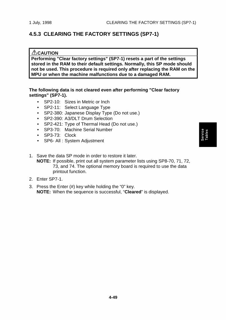
1 July, 1998 CLEARING THE FACTORY SETTINGS (SP7-1)
4-49
Ser
vice
Tab
les
4.5.3 CLEARING THE FACTORY SETTINGS (SP7-1)
CAUTIONPerforming "Clear factory settings" (SP7-1) resets a part of the settingsstored in the RAM to their default settings. Normally, this SP mode shouldnot be used. This procedure is required only after replacing the RAM on theMPU or when the machine malfunctions due to a damaged RAM.
The following data is not cleared even after performing "Clear factorysettings" (SP7-1).
• SP2-10: Sizes in Metric or Inch• SP2-11: Select Language Type• SP2-380: Japanese Display Type (Do not use.)• SP2-390: A3/DLT Drum Selection• SP2-421: Type of Thermal Head (Do not use.)• SP3-70: Machine Serial Number• SP3-73: Clock• SP6- All : System Adjustment
1. Save the data SP mode in order to restore it later.NOTE: If possible, print out all system parameter lists using SP8-70, 71, 72,
73, and 74. The optional memory board is required to use the dataprintout function.
2. Enter SP7-1.
3. Press the Enter (#) key while holding the “0” key.NOTE: When the sequence is successful, “Cleared” is displayed.

LOAD PROGRAM (SP8-20) 1 July, 1998
4-50
4.5.4 LOAD PROGRAM (SP8-20)
The software in the flash ROM on the MPU can be upgraded using the ROM board(a special tool), as follows.
NOTE: The ROM board is available as a service part. The part number is#A193 9351.
1. Before downloading new software, check the current version with SP1-42.
2. Turn off the main switch and disconnect the power plug.
3. Mount the U1 to U4 ROMs in the correct sockets on the ROM board [A] asshown above.
4. Remove the cover [B].
5. Plug the ROM board into the connector on the MPU.
6. Loosen the screw [C] to adjust the ROM board stand position. Then, retightenthe screw.
7. Connect the power plug and turn on the main switch.
8. Access SP8-20 and press the OK key. Press the Enter (#) key to startdownloading (the LCD displays 'Processing').
9. After completing the download (the LCD displays 'Completed'), check theupdated ROM version with SP1-42.
10. Leave the SP mode and turn off the main switch, then remove the ROM board.
C229M000.WMF
[B]
[C]
[A]

1 July, 1998 USER TOOLS
4-51
Ser
vice
Tab
les
4.5.5 USER TOOLS
Some items in the SP mode can be accessed by users with the User Tools. TheUser Tools key on the operation panel accesses these.
The following table shows all the user tools.
User Tools TableNo. Display Equivalent SP No.1-1 Auto Reset Time 3-0301-2 R. Counter Display 1-001-2, 1-002-21-3 Reset R. Counter 7-0111-4 Set User Code 2-1001-5 Key Card Setting 2-2201-6 Sizes in Metric or Inch 2-0101-7 Select Language Type 2-0111-8 Time Setting 3-0731-9 Auto On-line 2-410
1-10 Data Print 8-070-2, 8-072-22-1 Minimum Print Quantity 3-0012-2 Maximum Print Quantity 3-0022-3 Copy Count Display 2-2302-5 Panel Beeper 2-0302-6 LCD Contrast Adjustment 6-0503-1 Default Paper Type 2-020-33-2 Default Master Density 2-020-43-3 Default Original Mode 2-020-13-4 Magnification Ratio Settings 3-010-1 to -83-5 Class Mode Settings 3-1003-5 Class Entry Number Settings 3-100 to 3-1083-6 Default Photo/Lightness 2-020-93-7 Default Photo/Screen 2-020-103-8 Default Tint Mode 2-020-23-9 Margin Erase Area Settings 3-060-1 to -223-9 Custom Margin Erase Area Settings 3-061-1 to -2
3-10 Default On-line Paper Size 2-020-114-1 Default Auto Cycle Mode 2-020-64-2 Class Entry Per Orig. 2-2414-3 Paper Width Detection 2-042-14-4 ADF Orig. Size Detect 2-046-24-5 Platen Orig. Size Detect 2-046-14-6 Background ON/OFF 2-0314-7 Long Paper Mode 2-0604-8 Auto Combine Originals 2-0704-9 Combine Orig. Sep. Line 2-250
4-10 Default Auto Cycle Mode 2-260

USER TOOLS 1 July, 1998
4-52
No. Display Equivalent SP No.4-11 Skip Feed Mode Display 2-3204-11 Number of Skip Feeds 3-0514-12 Manual Idling Rotation 3-0904-13 Auto Quality Start 2-1104-14 Quality Start Mode Settings 3-091 to 3-0934-15 Exit Wing Position 2-1204-16 Print Restart in Class 2-2704-17 Job Sep. At Class Mode 2-2714-18 Ink/Master Left 2-2104-19 User1 Paper Type 2-4004-19 User2 Paper Type 2-4014-20 Auto Image Rotation 2-1504-21 Master Cut Length 2-1705-1 Stamp Type 2-3005-2 Default Stamp Size 2-3015-3 Default Stamp Density 2-3025-4 Default Stamp Position 2-3035-4 Stamp Position Adjustments 3-120 to 3-1285-5 User Stamp Size 2-3045-6 User Stamp Density 2-3055-7 Default User Stamp Position 2-3065-7 User Stamp Position Adjustments 3-130 to 3-1385-8 Register User Custom Stamps 8-100-1 to -45-9 Date Stamp Type 2-307
5-10 Default Date Stamp Position 2-3085-11 Date Stamp Position Adjustments 3-140 to 3-1435-12 Page Numbering Type 2-3095-13 Default Page Stamping Positions 2-310-1 to -25-14 Page Stamping Position Adjustments 3-150 to 3-1535-15 Register Makeup Pattern 8-1106-1 Master and Print Counters for Each User
Code1-030 to 1-040
6-1 Master Counter for All User Codes 1-031-16-1 Print Counter for All User Codes 1-031-26-2 Clear Counters for Each User Code 7-020-1 to -206-3 Register User Code 3-1106-4 Change User Code 3-1116-5 Clear User Code 3-1136-6 Key Operator Code 2-2906-7 Register Key Operator 3-1126-8 Restricted Access 2-291

1 July, 1998 MAINTENANCE TABLE
5-1
Pre
vent
ive
Mai
nte
nan
ce
5. PREVENTIVE MAINTENANCE
5.1 MAINTENANCE TABLE
The following items should be maintained periodically. There are two sets ofintervals - one based on time and the other based on print count. For maintenanceitems with entries in both of them, use whichever comes first.
C: Clean, R: Replace, L: Lubricate, A: Adjust
Time Print CounterIntervalItem 6M 1Y 2Y 3Y 300K 600K 1M 1.2M 2M
EM NOTE
Scanner/OpticsExposure Lamp C C C C Dry ClothMirror/Reflector C C C C Soft ClothScanner Guide Rail C C C C Dry ClothPlaten Cover /White Plate
C C C C DampCloth
Exposure Glass C C C C Dry ClothMaster FeedThermal Head C AlcoholPlaten Roller
C C C RExpectedlife is 6Kmasters.
Master EjectRollers
C C C C Alcohol
Master Eject Box C C C C Alcohol1st and 2nd DrumMaster Sensors
C Dry Cloth
Paper FeedPaper Pick-upRoller
C C R C R DampCloth
Paper Feed Roller C C R C R DampCloth
Paper Feed andPick-up Roller One-way Clutches
R R
Friction Pad C C R C R DampCloth
Feed Roller andTransport BeltRoller Bushings
L L L Motor Oil(SAE #20)
Feed Drive Gears L L L Grease(Alvania#2)
Paper DeliveryTransport Belts
R R
Paper End Sensor C C C C Dry Cloth

MAINTENANCE TABLE 1 July, 1998
5-2
Time Print CounterIntervalItem 6M 1Y 2Y 3Y 300K 600K 1M 1.2M 2M
EM NOTE
Registration/FeedTiming/ExitSensors
C C C C Dry Cloth
Registration Roller C C C C Dry ClothDrum and Ink SupplyCloth Screen R RDrum Drive Gearsand Cam
L L L Grease(Alvania#2)
Drum FlangeBushing
L L L Motor Oil(SAE #20)
In/Outside of Drum C C C C AlcoholInk Nozzle C C C C AlcoholOthersPressure Cylinder C C R C R Damp
ClothPaper Clamper (onPressure Cylinder)
C C R C R Dry Cloth
Timing BeltTension
A
ADF (Option)DF Feed Rollers C C C C Dry Cloth

1 July, 1998 EXTERIOR
6-1
Rep
lace
men
tA
dju
stm
ent
6. REPLACEMENT AND ADJUSTMENT
6.1 EXTERIOR
6.1.1 EXPOSURE GLASS, OPERATION PANEL, AND UPPER COVERS
A: Exposure glass (First, remove the left scale [B] and upper scale [C].)
D: Operation panel
E: Lower operation panel cover
F: Rear upper cover
G: Left scanner cover
H. Right scanner cover
C229R069.WMF
[A]
[D]
[B]
[C]
[E]
[F][G]
[H]

EXTERIOR 1 July, 1998
6-2
6.1.2 REAR AND LEFT COVERS
A: Rear cover
B: Left cover
C229R512.WMF
[A][B]

1 July, 1998 EXTERIOR
6-3
Rep
lace
men
tA
dju
stm
ent
6.1.3 FRONT DOOR, AND RIGHT FRONT AND RIGHT REAR COVERS
A: Front door
B: Right front cover
C: Right rear cover
C229R510.WMF
[A]
[B]
[C]

EXTERIOR 1 July, 1998
6-4
6.1.4 INNER COVER AND KNOB COVER
A: Inner cover
B: Knob cover
C229R511.WMF
[A]
[B]

1 July, 1998 COPY IMAGE ADJUSTMENT
6-5
Rep
lace
men
tA
dju
stm
ent
6.2 COPY IMAGE ADJUSTMENT
6.2.1 LEADING EDGE REGISTRATION ADJUSTMENT
PURPOSE: To adjust the leading edge registration on prints by changing theimage scanning start positions in platen and ADF modes.
ADJUSTMENT STANDARD:
Within 0 ± 2.0 mm (in platen mode)
Within 0 ± 2.5 mm (in ADF mode)
CAUTION: This adjustment is required every time the MPU has been replaced.
1. Turn on the main switch, and make a copy in platen mode.
NOTE: The image position on the trial print that is automatically made aftermaking a master tends to be inconstant. Do not use the trial print tocheck the copy image.
2. Measure the difference between the leading edge registration of the originaland the print. If the registration does not meet specifications, go to the nextstep.
3. Access SP6-2-1 (Scan Start Position Adjustment - Platen Mode).
4. Adjust the gap.
5. Exit the SP mode and make a copy.
6. Re-measure the leading edge registration to ensure it is within specifications. Ifthe registration meets specifications, go to the next step.
7. Make a copy in ADF mode and repeat the same steps using SP6-2-2 (ScanStart Position - DF Mode). The specification in ADF mode is 0 ± 2.5 mm.
NOTE: The master clamping position is adjustable using SP6-130 (Drum MasterClamp Registration). Changing the clamping position with this SP alsoadjusts the leading edge registration. Normally, do not use this SP modefor adjusting the leading edge registration.

COPY IMAGE ADJUSTMENT 1 July, 1998
6-6
6.2.2 SIDE-TO-SIDE REGISTRATION ADJUSTMENT
PURPOSE: To adjust the side-to-side image position on prints by changing themain-scan positions in platen and ADF modes.
ADJUSTMENT STANDARD:
Within 0 ± 2.0 mm (in platen mode)
Within 0 ± 2.5 mm (in ADF mode)
CAUTION: This adjustment is required every time the MPU has been replaced.
1. Turn on the main switch, and make a copy in platen mode.
NOTE: The image position on the trial print that is automatically made aftermaking a master tends to be inconstant. Do not use the trial print tocheck the copy image.
2. Measure the difference between the side-to-side edge registration of theoriginal and the print. If the registration does not meet specifications, go to thenext step.
3. Access SP6-1-1 (Main-scan Position - Platen Mode).
4. Adjust the gap.
5. Exit the SP mode and make a copy.
6. Re-measure the side-to-side registration to ensure it is within specifications. Ifthe registration meets specifications, go to the next step.
7. Make a copy in ADF mode and repeat the same steps using SP6-1-2 (Main-scan Position - DF Mode). The specification in ADF mode is 0 ± 2.5 mm.

1 July, 1998 COPY IMAGE ADJUSTMENT
6-7
Rep
lace
men
tA
dju
stm
ent
6.2.3 VERTICAL MAGNIFICATION ADJUSTMENT
PURPOSE: To adjust the vertical magnification to within the adjustment standardby changing the scanning speeds in platen and ADF modes.
ADJUSTMENT STANDARD:
Within 100 ± 1.0%
CAUTION: This adjustment is required every time the MPU has been replaced.
1. Turn on the main switch, and make a copy in platen mode.
NOTE: The image position on the trial print that is automatically made aftermaking a master tends to be inconstant. Do not use the trial print tocheck the copy image.
2. Measure the difference between the magnification of the original and the print.If the vertical magnification does not meet specifications, go to the next step.
3. Access SP6-11-1 (Scanning Speed - Platen Mode).
4. Adjust the value.
5. Exit the SP mode and make a copy.
6. Check the vertical magnification again to ensure it is within specifications. If thevertical magnification meets specifications, go to the next step.
7. Make a copy in ADF mode and repeat the same steps using SP6-11-2(Scanning Speed - DF Mode).
NOTE: The master feed speed during image writing can be adjusted with SP6-10(Master Writing Speed). Changing the speed with this SP also adjusts thevertical magnification. Normally, do not use this SP mode for adjusting thevertical magnification.

MPU AND I/O BOARD REPLACEMENT 1 July, 1998
6-8
6.3 MPU AND I/O BOARD REPLACEMENT
SP mode data and other adjustment data are stored in the backup RAM on theMPU. There are adjustable potentiometers on the I/O board.
Therefore, once the MPU and/or I/O boards are replaced, the followingadjustments are needed.
- When the MPU is replaced -
• The SP mode data returns to the default. Save the data SP mode in order torestore it later. If possible, print out all system parameter lists using SP8-70,71, 72, 73, and 74. (The optional memory board is required to use the dataprintout function.)
• Carry out all copy image adjustments. (See "6.2 Copy Image Adjustment".)• Sensor board unit calibration. (See "6.5.8 Sensor Board Unit Calibration".)• Master end sensor adjustment. (See "6.7.7 Master End Sensor Adjustment".)
NOTE: If you use the backup RAM [A](IC117) from the old MPU onthe new one, all data,including data in the SPmodes, will be restored. Youdo not have to do the aboveprocedures. (The batteryinside the RAM preserves thedata even if the RAM isremoved from the MPU.)
- When the I/O board is replaced -
• Carry out the adjustments forthe 1st drum master, 2nd drummaster, master eject, andmaster edge sensors. (Whenboth MPU and I/O board arereplaced, carry out the masterend sensor adjustment, also.)
C229R503.WMF[A]

1 July, 1998 MPU AND PSU OPENING PROCEDURES
6-9
Rep
lace
men
tA
dju
stm
ent
6.4 MPU AND PSU OPENING PROCEDURES
Opening the MPU
First, remove the rear exterior cover.
A: Memory board (If installed, as thisis an option.)
B: Flat cableNOTE: Gently pull out the lever
[C] to release the flatcable, as shown. It caneasily be damaged.Also, when reconnectingit, carefully push it backas shown [D].
Then, remove 7 screws securing theMPU bracket to flip over the MPU.
Opening the PSU
First, remove the rear exterior cover.
Then, remove 6 screws to flip over thePSU [E].
C229R032.WMF
C229R095.WMF
[A]
[B]
[E]
[C] [D]

SCANNER UNIT 1 July, 1998
6-10
6.5 SCANNER UNIT
6.5.1 LENS COVER
1. Remove the scales and exposure glass. (See 6.1.1 Exposure Glass, OperationPanel, and Upper Covers.)
2. Remove the flat cable [A] (1 screw).
3. Remove the right lens cover [B] (6 screws) and left lens cover [C] (5 screws).
C229R070.WMF
[A]
[B]
[C]

1 July, 1998 SCANNER UNIT
6-11
Rep
lace
men
tA
dju
stm
ent
6.5.2 SCANNER FRAME
1. Remove the platen cover (ADF).
2. Remove all parts indicated in 6.1.1 Exposure Glass, Operation Panel, andUpper Covers section.
3. Remove the exposure glass bracket [A] (1 screw).
4. Disconnect the platen cover sensor [B] and remove the lower rear scannerframe [C] (5 screws).
5. Disconnect the scanner H.P. sensor [D] and remove the upper rear scannerframe [E] (2 screws).
6. Remove the lower operation panel [F] (3 screws).
7. Remove the front scanner frame [G] (5 screws).
C229R071.WMF
[A]
[B]
[C]
[D]
[E]
[F]
[G]

SCANNER UNIT 1 July, 1998
6-12
6.5.3 ORIGINAL SIZE SENSOR AND LENS BLOCK/SBUASSEMBLY
Original Size Sensors
1. Remove the exposure glass. (See 6.1.1 Exposure Glass, Operation Panel, andUpper Covers.)
2. Remove the lens covers. (See 6.5.1 Lens Cover.)
3. Change the original size sensors [A]: two for 110/120 V machines and three for220/240 V machines (2 screws each).
Lens Block/SBU Assembly
1. Remove the exposure glass and operation panel. (See 6.1.1 Exposure Glass,Operation Panel, and Upper Covers.)
2. Remove the lens covers. (See 6.5.1 Lens Cover.)
3. Disconnect the flexible cable [B].
4. Remove the grounding wire [C] (1 screw).
5. Remove the lens block [D] (4 screws).
C229R072.WMF
[A]
[B]
[C][D]

1 July, 1998 SCANNER UNIT
6-13
Rep
lace
men
tA
dju
stm
ent
6.5.4 XENON LAMP
1. Remove the exposure glass and operation panel. (See 6.1.1 Exposure Glass,Operation Panel, and Upper Covers.)
2. Remove the scanner frames. (See 6.5.2 Scanner Frame.)
3. Remove the connector cover [A] (1 screw).
4. Press the lamp holder [B] down with a screwdriver, as shown.
5. Slide the xenon lamp [C] forward and remove it (1 connector).klqbW=klqbW=klqbW=klqbW= Do not touch the glass surface of the xenon lamp with your fingers.
6. After installing the new lamp, press the lamp holder up to the original positionso that it can hold the lamp properly.
C229R073.WMF
[A]
[B]
[C]

SCANNER UNIT 1 July, 1998
6-14
6.5.5 SCANNER H. P. SENSOR/PLATEN COVER SENSOR
1. Remove the exposure glass and upper rear cover. (See 6.1.1 Exposure Glass,Operation Panel, and Upper Covers.)
2. Replace the platen cover sensor [A] (1 connector).
3. Remove the scale bracket [B] (1 screw) and replace the scanner H.P. sensor[C].
C229R074.WMF
[A]
[B]
[C]

1 July, 1998 SCANNER UNIT
6-15
Rep
lace
men
tA
dju
stm
ent
6.5.6 SCANNER MOTOR
1. Remove the exposure glass and operation panel. (See 6.1.1 Exposure Glass,Operation Panel, and Upper Covers.)
2. Remove the lens covers. (See Lens Cover.)
3. Remove the scanner frames. (See Scanner Frame.)
4. Disconnect the cable [A].
5. Remove the tension spring [B].
6. Remove the motor and bracket [C] (2 screws).
7. Secure the new motor with the tension spring.
C229R075.WMF
[A]
[B]
[C]

SCANNER UNIT 1 July, 1998
6-16
6.5.7 SCANNER WIRE
1. Remove the exposure glass and operation panel. (See 6.1.1 Exposure Glass,Operation Panel, and Upper Covers.)
2. Remove the lens covers. (See 6.5.1 Lens Cover.)
3. Remove the scanner frames. (See 6.5.2 Scanner Frame.)
4. Remove the pin [A] securing the 1st scanner and remove the 1st scanner.
5. Remove the spring [B].
6. Loosen the screw [C] securing the wire tension bracket. Loosen the screw atthe opposite side.
7. Remove the scanner wire.
8. Wind the new scanner wire on the pulley in the correct direction as shown.
C229R076.WMF
[A]
[B]
[C]
1
2
3, 6
4
5
7
8

1 July, 1998 SCANNER UNIT
6-17
Rep
lace
men
tA
dju
stm
ent
9. Wind the end of the new wire with a ball as shown by steps 2 - 4 in theillustration on the previous page.
10. Wind the end of the new wire with a ring as shown by steps 5 - 7 in theillustration on the previous page.
11. Secure the screw of the wire tension bracket, with the wire tension springpulled as shown by step 7 in the illustration on the previous page.
12. Install the 1st scanner and adjust its position with the scanner positioning pins(P/N A0069104) [A]. Then clamp the 1st scanner with the scanner positioningpin as shown by step 8 in the illustration on the previous page.
13. Remove the positioning pins. After sliding the scanner to the left and rightseveral times, set the scanner positioning pins to check the clamp position andwire tension bracket position again.
C229R077.WMF
[A]

SCANNER UNIT 1 July, 1998
6-18
6.5.8 SENSOR BOARD UNIT CALIBRATION
PURPOSE: Perform the SBU auto calibration using the SP mode in the followingcases:• When the MPU is replaced• When the standard white plate located behind the original scale is
replaced.
PROCEDURE:
1. Place about 10 sheets of paper on the exposure glass.
2. Turn on the main switch and access the SP mode (Clear Modes ⇒ 1 ⇒ 0 ⇒ 7⇒ Clear/Stop).
3. Select SP6-32-1 (SBU Auto Calibration).
4. Press the Enter (#) key to start.
NOTE: When the sequence is successful, “Completed” is displayed on thedisplay.

1 July, 1998 MASTER EJECT SECTION
6-19
Rep
lace
men
tA
dju
stm
ent
6.6 MASTER EJECT SECTION
6.6.1 MASTER EJECT ROLLER UNIT
Unit Removal
First, open the front door.
A: Supporter
B: Master eject roller unit
Master Eject Sensor
First, remove the master eject roller unit.(See the procedure above.)
A: Master eject sensor cover
B: Master eject sensor
C229R083.WMF
C229R084.WMF
[A]
[B]
[A]
[B]

MASTER EJECT SECTION 1 July, 1998
6-20
6.6.2 MASTER EJECT DRIVE UNIT
Unit Removal
1. Slide out the master eject box and the master eject drive unit.
2. Remove the left exterior cover.
3. To remove the master eject drive unit [A], slide it out in the paper deliverydirection, and pull down the top of the unit towards the operation panel. (Seethe arrows in the illustration.)
NOTE: The master eject drive unit is connected to the cables from the sensorand the motor. Remove the master eject unit carefully.
C229R056.WMF
[A]

1 July, 1998 MASTER EJECT SECTION
6-21
Rep
lace
men
tA
dju
stm
ent
Sensors and Motors in the Master Eject Drive Unit
First, remove the master eject drive unit.(See the previous procedure.)
A: Master Eject Motor
B: Pressure Plate HP Sensor
C: Pressure Plate Limit Position Sensor
D: Pressure Plate Motor
C229R085.WMF
[A]
[B]
[C]
[D]

MASTER EJECT SECTION 1 July, 1998
6-22
6.6.3 MASTER EJECT SENSOR ADJUSTMENT
PURPOSE: To ensure that the sensor detects the ejected master properly.
CAUTION: 1) The sensor adjustment is required in the following cases:- When the sensor is replaced.- When the I/O board is replaced.
2) While adjusting, make sure to attach all exterior covers to avoidexternal light.
3) Do not turn the VRs excessively. Turn slowly until the LED turnsoff.
4) If the sensor is dirty, clean or replace it.5) For how to access SP mode, refer to the Service Program Mode
section.
PROCEDURE
1. Turn on the main switch, then accessSP6-20-1 (Sensor Voltage andThreshold Adjustment for Master EjectSensor).
NOTE: Make sure that the master ejectbox and drum are installed.
2. Remove the rear cover and access theI/O board. Turn VR303 [A] clockwiseuntil LED302 [B] lights.
3. The sensor input voltage is displayed onthe operation panel. Check that it isbetween 1.0 and 1.5 volts. If it is not, goback to step 2.
4. Leave the SP mode.
C229R104.WMF
[A][B]

1 July, 1998 MASTER EJECT SECTION
6-23
Rep
lace
men
tA
dju
stm
ent
6.6.4 REASSEMBLING THE MASTER PICK-UP ROLLER DRIVEGEARS
PURPOSE: When the master pick-up roller drive sector gear [A] or master ejectclamper drive arm [B] have been removed, they must be re-installedin the correct position.
PROCEDURE:
1. The master eject clamper drive arm [B] must be flush with the cutout in theframe, as shown.
2. Holding the arm in the above position, install the sector gear [A] so that thesmall positioning hole in the sector gear exactly overlaps the positioning hole inthe frame, as shown.
C229R105.WMF
[B][A]
2. This edge mustbe flush with thecutout.
1. The positioning hole in the gear mustoverlap the positioning hole in the frame.

MASTER FEED SECTION 1 July, 1998
6-24
6.7 MASTER FEED SECTION
6.7.1 MASTER MAKING UNIT REMOVAL
First, slide out the master making unit [A].
Then, remove it (2 screws [B]).
C229R034.WMF
[A][B]
[B]

1 July, 1998 MASTER FEED SECTION
6-25
Rep
lace
men
tA
dju
stm
ent
6.7.2 MASTER SET ROLLER AND PLATEN ROLLER
First, remove the master making unit from the machine.
A: Front bracket
B: Rear bracket
C: Master set roller unit
C229R087.WMF
C229R058.WMF
[A]
[B]
[C]

MASTER FEED SECTION 1 July, 1998
6-26
Disassemble the master set roller unit
D: Master set roller
NOTE: When re-installing the springs at the non-operation side, refer to the abovediagram.
E: Platen roller [E] (slide it towards the operation side)
C229R059.WMF
C229R040.WMF
[D]
[E]

1 July, 1998 MASTER FEED SECTION
6-27
Rep
lace
men
tA
dju
stm
ent
6.7.3 THERMAL HEAD
First, remove the platen roller.
A: Thermal head cover
B: Thermal head (Disconnect the thermal head connectors)
CAUTION: 1) After the replacement, adjust the input voltage.2) There is a small mylar [C] in the base. At reinstallation, make sure
that it is in the correct position. (Refer to 6.7.10 Master Feed MylarPositioning.)
3) Make sure that there is no foreign material on the thermal headsurface (especially on the heating elements).Don’t touch the surface with bare hands. (If you touch it, clean thesurface with alcohol.)
4) Similarly, do not touch the surface of the master film with barehands.
5) Connect and disconnect the connectors carefully.Keep them horizontal. Also, make sure that they are reconnectedfirmly.
6) Don’t touch the terminals of the connectors with bare hands.
C229R090.WMF
C229R061.WMF
[A]
[B]
[C]

MASTER FEED SECTION 1 July, 1998
6-28
6.7.4 SENSORS, MOTORS, AND CUTTER IN THE MASTERMAKING UNIT
Duct Entrance Solenoid
First, remove the master making unit from the machine.
A: Front platen roller bracket
B: Front cover
C: Master making unit right cover
C229R063.WMF
C229R091.WMF[C]
[A]
[B]
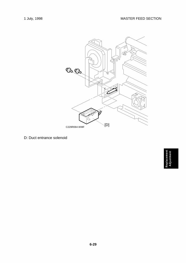
1 July, 1998 MASTER FEED SECTION
6-29
Rep
lace
men
tA
dju
stm
ent
D: Duct entrance solenoid
C229R064.WMF[D]

MASTER FEED SECTION 1 July, 1998
6-30
Cutter Unit, Platen Release Motor and Sensor, and Master Feed Clutch
First, remove the master making unit from the machine.
A: Rear platen roller bracket
B: Rear cover
C: Cable cover
Disconnect the connector [D] between the cutter unit and the cable.
Unhook the wire from the cable clamps [E].
C229R041.WMF
C229R120.WMF
[A]
[B]
[C]
[D]
[E]

1 July, 1998 MASTER FEED SECTION
6-31
Rep
lace
men
tA
dju
stm
ent
F: Cover bracket
G: Cutter unit
NOTE: Make sure that the mylar [H] is in the correct position when reinstalling thecutter unit. There are 6 of these mylars across the length of the cutter unit.(Refer to 6.7.10 Master Feed Mylar Positioning.)
I: Platen release motor
J: Platen release sensor
NOTE: Make sure that the gear is positioned correctly. Install it in accordance with6.7.9 Platen Release Cam Adjustment section.
C229R065.WMF
C229R042.WMF
[F]
[G]
[H]
[F][I]
[J]

MASTER FEED SECTION 1 July, 1998
6-32
K: Master feed clutch
NOTE: 1) Push the pawl [L] out from the centerto slide the clutch off the shaft.2) At installation, make sure that the stopper [M] is positioned as
shown.
C229R043.WMF
[M]
[K]
[L]

1 July, 1998 MASTER FEED SECTION
6-33
Rep
lace
men
tA
dju
stm
ent
Master Feed Motor
First, remove the master making unit from the machine.
A: Rear platen roller bracket
B: Master making unit rear cover
C: Master making unit right cover
C229R041.WMF
C229R057.WMF [C]
[A]
[B]

MASTER FEED SECTION 1 July, 1998
6-34
D: Thermal head cover
E: Stay
NOTE: Take care when removing the thermal head and the stay because theseare connected to a cable from a sensor.
F: Rail
G: Master feed motor
C229R060.WMF
C229R066.WMF
[D]
[E]
[F]
[G]

1 July, 1998 MASTER FEED SECTION
6-35
Rep
lace
men
tA
dju
stm
ent
Master Set Sensor
A: Thermal head cover
NOTE: Take care when removing the thermal head cover because it is connectedto the cable from the sensor.
B: Master set sensor
C229R090.WMF
C229R067.WMF
[A]
[B]

MASTER FEED SECTION 1 July, 1998
6-36
Master End Sensor
A: Rear platen roller bracket
B: Master making unit rear cover
C: Master making unit right cover
C229R041.WMF
C229R057.WMF
[A]
[B]
[C]

1 July, 1998 MASTER FEED SECTION
6-37
Rep
lace
men
tA
dju
stm
ent
D: Thermal head cover
E: Stay
NOTE: Be careful when removing the thermal head cover and the stay becausethese are connected to cables from sensors.
F: Master end sensor
C229R060.WMF
C229R068.WMF
[F]
[E]
[D]
[E]

MASTER FEED SECTION 1 July, 1998
6-38
6.7.5 MASTER VACUUM FAN POSITIONING
PURPOSE: To ensure that the master vacuum fans are installed the correct wayaround. If they are installed the wrong way around, there will be nosuction in the master buffer duct, resulting in master jams.
PROCEDURE:When installing the master vacuum fan, position the cable as shown in thediagram.
C229R103.WMF
[A]

1 July, 1998 MASTER FEED SECTION
6-39
Rep
lace
men
tA
dju
stm
ent
6.7.6 THERMAL HEAD VOLTAGE ADJUSTMENT
PURPOSE: To maintain printing quality when making masters and to extend thelife time of the thermal head.
CAUTION• The voltage value affects the durability of the thermal head, and is different for
each thermal head. Refer to the exact voltage value that is labeled on eachthermal head.
• The adjustment range is between + 0 and – 0.1 volts from the specified value.Never set it out of this range even if there is an image quality problem.
1. Turn off the main switch. Then,remove the upper rear exteriorcover to access the thermal headpower supply board.
2. Check the voltage on the thermalhead decal.NOTE: The value is different for
each thermal head.
3. Turn on the main switch andaccess the SP mode (ClearModes ⇒ 1 ⇒ 0 ⇒ 7 ⇒Clear/Stop). Then, select SP 5-402 (the thermal head voltageadjustment of the output mode).
4. Press the Start key to apply the voltage to the thermal head. The voltage iscontinually supplied while the Start key is held down.
NOTE: As another way to apply the voltage, press the key instead of theStart key. However, once the key is pressed, the machine will notstop supplying the voltage until you press the Clear/Stop key or cancelthe SP mode. To protect the thermal head, never leave the voltage onfor a long time.
5. Measure the voltage between pins TP1 (VHD) and TP2 (GND) on the powersupply board. Check that it is between + 0 and – 0.1 volts from the specifiedvalue that you read from the decal in step 2.
6. If needed, adjust the voltage by turning VR1 on the power supply board.
NOTE: - To increase the voltage: Turn VR1 clockwise- To reduce the voltage: Turn VR1 counterclockwise
7. Press the Clear Modes key to leave the SP mode.
C229R092.WMF

MASTER FEED SECTION 1 July, 1998
6-40
6.7.7 MASTER END SENSOR ADJUSTMENT
PURPOSE: To ensure that the sensor detects the end mark (a solid black area) onthe master roll.
CAUTION: 1) The sensor adjustment is required in the following cases:- When the sensor is replaced.- When the MPU is replaced.
2) If the sensor is dirty, clean or replace it.3) For how to access the SP mode, refer to the Service Program
Mode section.
PROCEDURE:
1. Turn on the main switch, then access SP6-20-4 (Sensor Voltage and ThresholdAdjustment for Master End Sensor).
2. The sensor threshold value is displayed on the operation panel. Enter 0.5(volts) with the number keys.
3. Leave the SP mode.

1 July, 1998 MASTER FEED SECTION
6-41
Rep
lace
men
tA
dju
stm
ent
6.7.8 MASTER EDGE SENSOR ADJUSTMENT
PURPOSE: To ensure that the sensor detects the master properly.
CAUTION: 6) The sensor adjustment is required in the following cases:- When the sensor is replaced.- When the I/O board is replaced.
7) While adjusting, make sure to attach all exterior covers to avoidexternal light.
8) Do not turn the VRs excessively. Turn slowly until the LED turnsoff.
9) If the sensor is dirty, clean or replace it.10) For how to access the SP mode, refer to the Service Program
Mode section.
PROCEDURE:
1. Slide out the master making unit.
2. Remove the master roll.NOTE: The master roll must not be installed for this adjustment.
3. Remove the front platen roller bracket [A] and the front cover [B].
C229R063.WMF
[A]
[B]

MASTER FEED SECTION 1 July, 1998
6-42
4. Close the duct entrance plate [A] by hand and secure the link [B] with tape.NOTE: This procedure must be done to obtain fine adjustment.
5. Slide in the master makingunit and make sure that thedrum is installed.
6. Turn on the main switch,then access SP6-20-6(Sensor Voltage andThreshold Adjustment forMaster Edge Sensor).
7. Remove the rear cover andaccess the I/O board. TurnVR307 [C] clockwise untilLED303 [D] lights.
8. The sensor input voltage isdisplayed on the operationpanel. Check that it isbetween 0.85 and 0.95volts. If it is not, repeat step7.
9. Leave the SP mode.
C229R533.WMF
C229R104.WMF [C]
[D]
[A]
[B]

1 July, 1998 MASTER FEED SECTION
6-43
Rep
lace
men
tA
dju
stm
ent
6.7.9 PLATEN RELEASE CAM ADJUSTMENT
PURPOSE: Once the platen pressure release mechanism is disassembled, theplaten release cam [A] must be reinstalled in the correct position.
PROCEDURE:When tightening the screws to secure the mechanism, make sure that the smallholes in the gears [B] are in line with the cutouts in the bracket, as shown.
C229R093.WMF
[A]
[B]

MASTER FEED SECTION 1 July, 1998
6-44
6.7.10 MASTER FEED MYLAR POSITIONING
PURPOSE: These strips of mylar are easily put in the wrong position. Take careto set these properly to avoid master jams.
PROCEDURE:When replacing or removing the thermal head, the cutter unit, the master duct, orthe guide plate of the lower master feed control roller, install the lower tension rolleror lower master feed control roller as shown in the illustration.
C229R114.WMFC229R115.WMF
C229R113.WMF
C229R112.WMF
OKNG
Thermal Head BaseBefore the tension roller
Cutter UnitAfter the tension roller
Lower Master Feed Control RollerExit Guide Plate
Buffer Duct Entrance PlateBefore the Master Feed Control Roller
OKNG
OKNG OKNG

1 July, 1998 DRUM
6-45
Rep
lace
men
tA
dju
stm
ent
6.8 DRUM
6.8.1 DRUM CLOTH SCREEN
1. Remove the drum guide [A].
NOTE: Do not settle the drum unit upside down. However, if you do settle itupside down, wipe off the ink around the ink roller beforehand (usingSP 2-40, select OFF in ink detection mode, and feed paper until inkends).
2. Loosen the stopper [B] (the drum lock solenoid), then rotate the drum until theclamper unit is positioned on the top of the drum.
3. Remove the drum screen [C].
C229R045.WMF
C229R046.WMF
C229R086.WMF
[A]
[C]
[B]

DRUM 1 July, 1998
6-46
CAUTION: 1) Do not scratch the cloth screen or metal screen.2) When replacing the cloth screen, spread the screen around the
metal screen while strongly pulling the stay [A]. Adjust the stay sothat it is parallel to the master clamper, then tighten the screws.
3) When installing the new screen, the black sensor patches [B] mustbe to the left of the master clamper. (Position the clamper on the topof the drum, and view from the operation side - refer to the upperillustration.)
4) Make sure that the correct side of the screen is facing up. (Refer tothe lower illustration.)
5) Make sure that the stays forsecuring the cloth screen arepositioned correctly. (Refer tothe lower illustration.)
6) Make sure that the insidescreen is not wrinkled whilespreading it around the drum.
C229R048.WMF
C229R047.WMF
[A]
[B]
Inside
Outside

1 July, 1998 DRUM
6-47
Rep
lace
men
tA
dju
stm
ent
6.8.2 DRUM MASTER CLAMPER AND METAL SCREEN
NOTE: Remove the cloth screen first.
1. Remove the drum clamper [A].
NOTE: To remove the clamper screws on theoperation panel side, turn the drum intoposition and pull out the lever [B]. Torotate the drum, release the stopper [C]on the rear of the drum.
CAUTION: 1) When replacing the drum clamper, install the spring on the oppositeside as shown in the illustration.
2) Do not settle the drum unit upside down. However, if you do settle itupside down, wipe off the ink around the ink roller beforehand (usingSP 2-40, select OFF in ink detection mode, and feed paper until inkends).
2. Remove the metal screen [D].
C229R049.WMF
C229R086.WMF
C229R050.WMF
[D]
[A]
[B][C]

DRUM 1 July, 1998
6-48
CAUTION: 1) Do not scratch the cloth screen or metal screen.2) Make sure that the correct end of the metal screen is
overlapping. (Refer to the lower right part of the upperillustration.)
3) When attaching the metal screen to the drum flanges, wrap it sothat the gap is correct. (Refer to the upper part of the upperillustration.)
4) When installing the master clamper [C], make sure that it is thecorrect way around. The side with the sandpaper [B] must befacing the black patch [A].
5) Do not allow the inside of the master clamper to become dirtywith ink. If it is dirty with ink, the master may slip off and theimage position on the prints will move toward the trailing edge ofthe print during a printing run.
6) Use a cloth dampened with water to clean the inside of themaster clamper. Do not use alcohol or other solvents. Theclamping force of the magnet will be weakened.
C229R110.WMF
C229R111.WMF
0 to 0.3 mm
0 to 0.3 mmThe standard position for the metalscreen (the left side overlaps, asviewed from the operation panel).
Operation Side
[A][B]
[C]

1 July, 1998 DRUM
6-49
Rep
lace
men
tA
dju
stm
ent
6.8.3 MOTORS AND SENSORS IN THE DRUM
NOTE: Remove the cloth screen and metal screen first.
1. First, pull out the ink cartridge holder.A: Drum shift motorB: Ink pump motorC: Drum shift HP sensor
NOTE: When reinstalling the drum shift motor unit, insert the bearings [D] intothe drum flange edge, as shown.
C229R052.WMF
[A]
[B]
[C]
[D]

DRUM 1 July, 1998
6-50
2. E: Ink detection pin
3. First, remove the ink pump unit.F: Ink pumpG: Ink pump sensor
4. H: Idling roller motor
C229R051.WMF
C229R053.WMF
[E]
[F]
[G]
[H]

1 July, 1998 DRUM
6-51
Rep
lace
men
tA
dju
stm
ent
5. First, remove the sensor bracket (1 screw).I: Idling roller HP sensor
C229R054.WMF
[I]
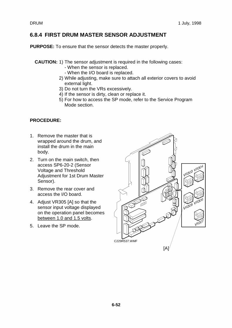
DRUM 1 July, 1998
6-52
6.8.4 FIRST DRUM MASTER SENSOR ADJUSTMENT
PURPOSE: To ensure that the sensor detects the master properly.
CAUTION: 1) The sensor adjustment is required in the following cases:- When the sensor is replaced.- When the I/O board is replaced.
2) While adjusting, make sure to attach all exterior covers to avoidexternal light.
3) Do not turn the VRs excessively.4) If the sensor is dirty, clean or replace it.5) For how to access the SP mode, refer to the Service Program
Mode section.
PROCEDURE:
1. Remove the master that iswrapped around the drum, andinstall the drum in the mainbody.
2. Turn on the main switch, thenaccess SP6-20-2 (SensorVoltage and ThresholdAdjustment for 1st Drum MasterSensor).
3. Remove the rear cover andaccess the I/O board.
4. Adjust VR305 [A] so that thesensor input voltage displayedon the operation panel becomesbetween 1.0 and 1.5 volts.
5. Leave the SP mode.
C229R537.WMF
[A]

1 July, 1998 DRUM
6-53
Rep
lace
men
tA
dju
stm
ent
6.8.5 SECOND DRUM MASTER SENSOR ADJUSTMENT
PURPOSE: To ensure that the sensor detects the master properly.
PROCEDURE:
CAUTION: 1) The sensor adjustment is required in the following cases:- When the sensor is replaced.- When the I/O board is replaced.
2) While adjusting, make sure to attach all exterior covers to avoidexternal light.
3) Do not turn the VRs excessively.4) If the sensor is dirty, clean or replace it.5) For how to access the SP mode, refer to the Service Program
Mode section.
1. Remove the master that is wrapped around the drum, and install the drum inthe main body.
2. Remove the knob cover [A] and turn the knob until the indicator moves to thepoint shown [B].
NOTE: This step moves the black patch on the drum screen to the sensor.
C229R534.WMF
[A]
[B]

DRUM 1 July, 1998
6-54
3. Remove the rear cover andaccess the I/O board.
4. Fully turn VR306 [A]counterclockwise.NOTE: The sensor output
becomes minimum.
5. Turn on the main switch, thenaccess SP6-20-3 (SensorVoltage and ThresholdAdjustment for 2nd DrumMaster Sensor).
6. The sensor input voltage isdisplayed on the operationpanel. Check if it is 0.3 volts ormore.
7. If the sensor input voltage is0.3 volts or more, adjustmentis completed.
8. If the sensor input voltage isless than 0.3 volts, adjustVR306 [A] so that the sensorinput voltage becomesbetween 0.3 and 0.4 volts.
9. Leave the SP mode.
C229R537.WMF [A]

1 July, 1998 DRUM
6-55
Rep
lace
men
tA
dju
stm
ent
6.8.6 INK ROLLER GAP ADJUSTMENT
PURPOSE: To ensure that ink on the ink roller spreads evenly on the drumscreen.
PROCEDURE:
1. Take out the drum unit from the machine.
2. Remove the cloth and metal screens from the drum unit.
3. Wipe off the ink around the ink roller and the doctor roller.
4. Insert a 0.08-mm gap gauge between the doctor roller and the ink roller. Then,make sure that a 0.1-mm gauge cannot pass through the gap.
NOTE: Check the gap at the left, center, and right.
5. If the gap is not correct, loosen the screws [A] on both sides and adjust the gapby turning the eccentric bushings [B] at each side.
C229R055.WMF
[B]
[A]
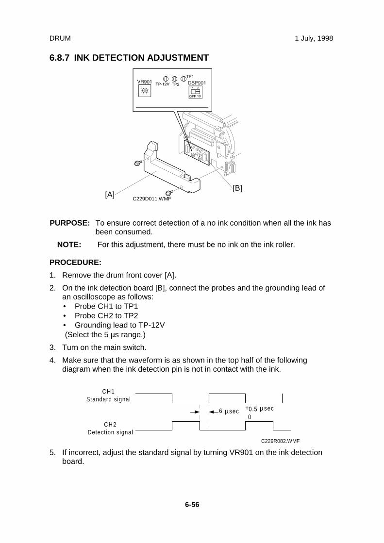
DRUM 1 July, 1998
6-56
6.8.7 INK DETECTION ADJUSTMENT
PURPOSE: To ensure correct detection of a no ink condition when all the ink hasbeen consumed.
NOTE: For this adjustment, there must be no ink on the ink roller.
PROCEDURE:
1. Remove the drum front cover [A].
2. On the ink detection board [B], connect the probes and the grounding lead ofan oscilloscope as follows:• Probe CH1 to TP1• Probe CH2 to TP2• Grounding lead to TP-12V(Select the 5 µs range.)
3. Turn on the main switch.
4. Make sure that the waveform is as shown in the top half of the followingdiagram when the ink detection pin is not in contact with the ink.
5. If incorrect, adjust the standard signal by turning VR901 on the ink detectionboard.
C229D011.WMF
6 +0.5 µ0
CH1Standard signal
CH2Detection signal
µsec sec
C229R082.WMF
[A][B]

1 July, 1998 PAPER FEED SECTION
6-57
Rep
lace
men
tA
dju
stm
ent
6.9 PAPER FEED SECTION
6.9.1 PAPER TABLE UNIT
1. Remove the inner cover and the rear cove. (See 6.1 Exterior section.)
2. From the rear of the machine, swing out the MPU. (See 6.4 MPU and PSUOpening Procedures.)
3. Remove the following parts:A: Two springsB: Front bracket (2 screws)C: Rear bracket (1 screw)
4. Disconnect 4 connectors going to the unit, then remove the paper table unit [D](6 screws).
C229R101.WMF
[A]
[D]
[B]
[A]
[C]

PAPER FEED SECTION 1 July, 1998
6-58
6.9.2 PAPER FEED ROLLER, PICK-UP ROLLER, AND FRICTION PAD
A: Pick-up roller (1 clip)
B: Paper feed roller (1 clip)
C: Friction pad
C229R513.WMF
[A]
[B]
[C]

1 July, 1998 PAPER FEED SECTION
6-59
Rep
lace
men
tA
dju
stm
ent
6.9.3 PAPER WIDTH DETECTION BOARD
First, remove the rear cover(3 screws).
B: Paper table rear coverNOTE: Carefully push
out the 2 hooks[A] with ascrewdriver.
C: Sensor cover (2 screws)
D: Paper width detectionboard (1 screw, 1connector)
6.9.4 PAPER HEIGHT SENSOR
First, remove the mastermaking unit (see 6.7.1 MasterMaking Unit Removal).
A: Feed cover (2 screws)
B: Paper height sensor (1screw, 1 connector)
NOTE: When reinstallingthe master makingunit, push it inwhile pressing therail with aforefinger. Thensecure the screws.
C229R033.WMF
C229R035.WMF
[B]
[C]
[D][A]
[A]
[B]

PAPER FEED SECTION 1 July, 1998
6-60
6.9.5 FEED PRESSURE DETECTION BOARD
1. Remove the mastermaking unit. (See 6.7.1Master Making UnitRemoval.)
A: Feed cover (2 screws)
2. Swing out the MPU. (See6.4 MPU and PSUOpening Procedures.)
B: Rear rail guideC: Feed pressuredetection board (2screws)
C229R500.WMF
C229R078.WMF
[A]
[B]
[C]

1 July, 1998 PAPER FEED SECTION
6-61
Rep
lace
men
tA
dju
stm
ent
6.9.6 PAPER REGISTRATION AND FEED TIMING SENSORS, AND UPPER REGISTRATION ROLLER
1. Remove the master making unit. (See 6.7.1 Master Making Unit Removal.)
A: Feed cover (2 screws)
2. Swing out the MPU. (See 6.4 MPU and PSU Opening Procedures.)
B: Pulley cover (1 screw)C: Paper feed motor (2 screws)D: Pulley (1 E-ring)
NOTE: Do not lose the key [E] from the pulley.
C229R500.WMF
C229R096.WMF
[B][E]
[C]
[D]
[A]

PAPER FEED SECTION 1 July, 1998
6-62
3. E: Right paper guide plate (1 screw)F: Paper feed roller (1 clip)G: Pick-up roller (1 clip)
4. Remove the clips [H] and slide the bushing [I] towards the operation side.
J: Paper feed roller unit
C229R097.WMF
[E]
[F]
[G]
[H]
[I]
[J]

1 July, 1998 PAPER FEED SECTION
6-63
Rep
lace
men
tA
dju
stm
ent
5. K: Rear rail guide (2 screws)L: Connectors from the feed pressure detection board
6. Remove the front exterior cover and inner cover.
M: Front rail guide (2 screws)N: Feed pressure unit [C] (4 screws)
C229R098.WMF
[L]
[K]
[M]
[N]

PAPER FEED SECTION 1 July, 1998
6-64
7. O: Sensor bracket (1 screw).
8. Remove the paper registration and feed timing sensors from the bracket.
9. P: Upper registration roller
C229R036.WMF
C229R527.WMF
[O]
[P]

1 July, 1998 PAPER FEED SECTION
6-65
Rep
lace
men
tA
dju
stm
ent
6.9.7 LOWER REGISTRATION ROLLER
- From the rear -
1. Swing out the MPU. (See 6.4 MPU and PSU Opening Procedures.)
2. Remove the pulley cover [D] and the bracket [C] (3 screws, 7 connectors).
3. Remove the registration motor [F] (2 screws, 1 connector).
4. Remove the pulley [E] (2 Allen screws).
5. Remove the bearing holder [B] and the bearing [A] (2 screws).
-From the front -
6. Remove the front exterior cover (4 screws) and the inner cover (5 screws).
7. Remove the bearing holder [G] and the bearing [H] (2 screws).
8. Pull out the registration roller [I] towards the operation side.
C229R037.WMF
C229R038.WMF
[A][B]
[C]
[D]
[E]
[F]
[G][H]
[I]

PAPER FEED SECTION 1 July, 1998
6-66
6.9.8 REGISTRATION ROLLER LIFTING CAM REMOVAL
1. Swing out the MPU. (See 6.4 MPU and PSU Opening Procedures.)
2. Remove the pulley cover [A] and the bracket [B] (3 screws, 7 connectors).
3. Remove the registration roller lifting cam [C].
CAUTION: There is the set position for the cam. When reinstalling the cam, followRegistration Roller Lifting Cam Position Adjustment on the next page.
C229R501.WMF
[A]
[B]
[C]

1 July, 1998 PAPER FEED SECTION
6-67
Rep
lace
men
tA
dju
stm
ent
6.9.9 REGISTRATION ROLLER LIFTING CAM POSITION ADJUSTMENT
PURPOSE: To ensure smooth paper feed from the registration roller to the drum.
CAUTION: Make sure that the drum is at home position before the adjustment.
1. When installing the registration roller lifting cam [A] on the shaft, align the camfollower (a bushing) at the center or within two divisions to the right of thecenter.
2. If the cam follower cannot be put in the correct place, try to change the gearmeshing. Also, try to readjust the position by loosening the screw holding thecam to the gear.
NOTE: To obtain a perfect adjustment, you must take out any gear play byapplying clockwise pressure to the cam (with the gear) during theadjustment.
C229R039.WMF
[A]

PAPER FEED SECTION 1 July, 1998
6-68
6.9.10 PAPER TABLE HEIGHT ADJUSTMENT
PURPOSE: To ensure smooth paper feed
1. Open the paper table. (There must be no paper.)
2. Turn on the main switch, then access SP 5-80-1 ("Paper Table Motor Up" in theoutput test mode).
3. In the SP mode, hold down the Start key to lift the paper table until it stops.
4. After the paper table stops, check if the distance [A] between the lower edge ofthe stay and the upper face of the table until it is 76.5 mm.
5. If the distance is not correct, adjust the upper limit position of the paper table bychanging the paper height sensor position. To do this, loosen the screw andmoves the sensor bracket [B] up or down.
NOTE: - To lower the stop position of the paper table: Moves the bracketdown.- To raise the stop position of the paper table: Moves the bracket up.
C229R514.WMF
C229R080.WMF
[B]
[A]

1 July, 1998 PAPER FEED SECTION
6-69
Rep
lace
men
tA
dju
stm
ent
6.9.11 TIMING BELT TENSION ADJUSTMENT FOR THE PAPERFEED MOTOR
PURPOSE: To ensure smooth paper feed
1. Make sure that the distance between the motor and the flange is 8.5 ± 0.5 mm.
2. Apply a 500g load to the center of the belt using a tension gauge. Make surethat the belt deflects between 2 to 4 mm. If the tension is incorrect, move themotor up or down.
C229R540.WMF
2 ~ 4 mm
8.5 ± 0.5 mm

PAPER FEED SECTION 1 July, 1998
6-70
6.9.12 TIMING BELT TENSION ADJUSTMENT FOR THE REGISTRATION MOTOR
PURPOSE: To ensure smooth paper feed.
1. Make sure that the distance between the end of the lower registration rollershaft and the edge of the pulley is 0 ± 0.5 mm.
2. Apply a 500g load to the center of the belt using a tension gauge. Make surethat the belt deflects between 2 to 4 mm. If the tension is incorrect, move themotor up or down.
C229R539.WMF
2 to 4 mm
0 ± 0.5 mm

1 July, 1998 PAPER FEED SECTION
6-71
Rep
lace
men
tA
dju
stm
ent
6.9.13 PAPER FEED AND SEPARATION PRESSUREADJUSTMENT
Paper feed pressure adjustment
PURPOSE: To ensure smooth paper feed from the paper table.
• The user has a choice of three different settings for the paper feed pressure(Standard, Frequent, Very Frequent). The user sets this between jobs dependingon how often they think no-feed errors are occurring.
• The setting is returned to the default by pressing the Clear Modes key or turningthe main switch off and back on. The default setting is “Standard”.
• The pressure applied for each setting can be adjusted by SP mode.
1. Select SP mode “6” (Adjustment mode).
2. Input “91” with the number keys, then press the Enter key.NOTE: SP90 is for special paper types (basically for envelopes), SP91 is for
standard paper types, and SP92 is for thick paper. If the user hasprogrammed as User 1 or User 2, you can change the paper feedpressures with SP93 and SP94.
3. Change the settings as necessary.• Defaults for SP91 – Standard: 3, Frequent: 5, Very Frequent: 6• The available pressure levels are from 0 to 6. (0 is the weakest, 6 is the
strongest.)
Paper separation pressure adjustment
PURPOSE: To ensure paper separation.
• The user has a choice of three different settings for the separation pressure(Standard, Frequent, Very Frequent). The user sets this between jobs dependingon how often they think multi-feed errors are occurring.
• The setting is returned to the default by pressing the Clear Modes key or turningthe main switch off and back on. The default setting is “Standard”.
• The pressure applied for each setting can be adjusted by SP mode.
1. Select SP mode “6” (Adjustment mode).
2. Input “96” with the number keys, then press the Enter key.NOTE: SP95 is for special paper types, SP96 is for standard paper types, and
SP97 is for thick paper. If the user has programmed as User 1 or User2, you can change the paper feed pressures with SP98 and SP99.
3. Change the settings as necessary.• Defaults for SP96 – Standard: 2, Frequent: 4, Very Frequent: 6• The available pressure levels are from 0 to 6. (0 is the weakest, 6 is the
strongest.)

PAPER FEED SECTION 1 July, 1998
6-72
6.9.14 PAPER FEED LENGTH ADJUSTMENT
Paper Feed Motor Stop Timing Adjustment
PURPOSE: To ensure that the paper reaches the registration roller properly.Changing the paper feed motor stop timing with SP6-116-3 changesthe paper feed length for the paper feed roller.
CAUTION: Do not change SP6-110 and 6-111 (these change the paper feedstart timing).
PROCEDURE:
1. Turn on the main switch, then access the SP mode.
2. Enter SP6-116-3.
3. Increase or decrease the value on the display.
NOTE: 1) Before changing the value, check the current setting, in case youneed to recover the previous setting. (Default for SP6-116-3 – "25")
2) Changing the value by +1 increases the paper feed motor's on-timeand feeds the paper an extra 0.3 mm.
4. Leave the SP mode, then check the paper feed performance. If the problem stilloccurs, repeat the above steps.

1 July, 1998 PAPER FEED SECTION
6-73
Rep
lace
men
tA
dju
stm
ent
Paper Clamping Timing Adjustment
PURPOSE: To ensure that the paper reaches the paper clamper on the pressurecylinder properly. Changing the paper clamping timing with SP6-116-1changes the paper feed length for the paper registration roller.
CAUTION: Do not change SP6-112 to 6-115 (these change the registrationmotor start timing). In addition, do not change SP6-116-2, -4, -6, or -7.
PROCEDURE:
1. Turn on the main switch, then access the SP mode.
2. Enter SP6-116-1.
NOTE: The paper clamping timing depends on the paper type selected at theoperation panel. SP6-116-1 is the adjustment for normal paper only.For thick paper, use SP6-116-5. (Note that in thick paper mode, paperclamping is not done.)
3. Increase or decrease the value on the display.
NOTE: 1) Before changing the value, check the current setting, in case youneed to recover the previous setting. (Default for SP6-116-1 – "143,"for SP6-116-5 – "150")
2) Changing the value by +1 decreases the registration motor's on-timeand feeds the paper 0.3 mm less.
4. Leave the SP mode, then check the paper feed performance. If the problem stilloccurs, repeat the above steps.

PRINTING SECTION 1 July, 1998
6-74
6.10 PRINTING SECTION
6.10.1 PRESSURE CYLINDER
NOTE: Take care when removing and replacing the pressure cylinder, becausethe pressure cylinder is made of soft rubber. Also, the encoder on the rearof the cylinder is easily damaged
Removal Procedure
1. Remove the drum.
2. Remove the bracket [A] (1 screw, 1 connector).
3. Remove the left exterior cover (5 screws).
4. Remove the paper delivery unit. (See "6.12.1 Paper Delivery Unit and Air KnifeFan Unit" section.)
5. Remove the exit pawl. (See "6.12.5 Paper Exit Pawl Removal" section.)
6. Remove the paper clamper [D] (2 screws, ground wire [B]).
7. Remove the blinding cover [C] from the inner cover (1 screw).
C229R001.WMF
[A]
[B]
[C]
[D]

1 July, 1998 PRINTING SECTION
6-75
Rep
lace
men
tA
dju
stm
ent
8. Turn the cylinderclockwise 80 degrees, sothat the positioning hole[A] in the side of thecylinder is at the top. (Theflat part of the cylinderfaces the upper right side,as shown.)
9. Remove the screw andflip over the stopper [B].
C229R526.WMF
C229R002.WMF
[B]
[A]

PRINTING SECTION 1 July, 1998
6-76
10. Put the right hand into theside trapezoid hole (forremoving lower wrappingjams), and support thebottom of the cylinder.
11. Pull it a little toward you(to disengage the jointbehind the cylinder).Then, push up to thedrum position.
CAUTION: There is theencoder plateat the rear ofthe cylinder.Be careful notto damage itwhenremoving thecylinder.
12. Pull the cylinder towardyou, and rest put it onthe flat area of the innercover [A].
13. With the left hand, holdthe bearing tightly,putting fingers into theholes as shown.
14. Support the rear of thepressure cylinder withthe right hand. Then,bring out the cylinderusing both hands.
C229R003.WMF
C229R004.WMF
[A]

1 July, 1998 PRINTING SECTION
6-77
Rep
lace
men
tA
dju
stm
ent
Reinstallation procedure
CAUTION: Take care not to turnthe drive accidentallyafter removing thecylinder. When thedrive is in position, thecutout (forengagement) in thedrive conductor (whitedisk) [A] is positionedhorizontally but leansto the upper right justslightly.
1. Hold the pressure cylinder sothat the round hole [C] isuppermost. Rest the pressurecylinder on the flat area of theinner cover [D].
CAUTION: There is anencoder plate [B] atthe rear of thecylinder. Be carefulnot to damage itwhen installing thecylinder.
2. With the left hand, hold thebearing tightly, putting fingersinto the holes as shown.
3. Support the rear of thepressure cylinder with the righthand. Put the right hand intothe side trapezoid hole (forremoving lower wrappingjams), and support the bottomof the cylinder.
C229R005.WMF
C229R004.WMF
[A]
[D]
[C]
[B]

PRINTING SECTION 1 July, 1998
6-78
4. Then, put the pressure cylinderinto the hole where the drumwas using both hands.
5. Install the pressure cylinder,while positioning the thinnestpart of the shaft of the bearing[A] with the clamper cam (theblack cam) as shown to theright. Position the bearing [A]on the bearing holder.
6. While the round hole [B] isuppermost, push the pressurecylinder towards the non-operation side (to engage thejoint behind the cylinder).
NOTE: 1) If it cannot enter, pushwhile turning thepressure cylinder alittle. Check if the jointis engaged properly byturning the cylinderslightly.
2) Set the bearing stopper[C] as shown.
C229R538.WMF
C229R006.WMF[C]
[B]
[A]

1 July, 1998 PRINTING SECTION
6-79
Rep
lace
men
tA
dju
stm
ent
6.10.2 FEED START SENSOR AND FEED ENCODER
1. Fist, remove the pressure cylinder. (See 6.10.1 Pressure Cylinder section.)
2. From the rear of the machine, swing out the MPU. (See 6.4 MPU and PSUOpening Procedures.)
3. Disconnect the connectors [D] from the rear of the machine.
4. Remove the feed encoder [B] and feed start sensor [C].
CAUTION: Make sure if there is agap [A] between thesensor bracket and theprinting pressurerelease arm [B]. Theremust be no gap or lessthan 0.2 mm.
C229R007.WMF
C229R117.WMF
[A]
[B]
[D]
[A]
[B]
[C]

PRINTING SECTION 1 July, 1998
6-80
6.10.3 PRINTING PRESSURE ADJUSTMENT
PURPOSE: To improve the print results.
1. Move the printing pressure bracket to its highest position, then tighten thescrew [A].
2. Adjust the clearance [C] to be 6.6 ± 0.3 mm by turning the bolt [B].
C229R009.WMF
[A]
[B]
[C]

1 July, 1998 PRINTING SECTION
6-81
Rep
lace
men
tA
dju
stm
ent
6.10.4 PRINTING PRESSURE RELEASE ARM GAP ADJUSTMENT
PURPOSE: To ensure that printing pressure release lever is disengaged whenthe printing pressure release solenoid is energized.
1. Rotate the printing pressure cams so that the arm moves to the lower mostposition.
NOTE: Use the main drive rotation knob. When the top of the cam meets thebearing [A] during turning the knob, the arm is at to the lower mostposition.
2. Adjust the clearance between the hook and the printing pressure release armby moving the bracket [B] up and down. The clearance must be 0.2 ± 0.1 mm.
3. Do the same at the non-operation side.
C229R010.WMF[B]
0.2 ± 0.1 mm
[A]

MAIN DRIVE AND IMAGE UP/DOWN SHIFTING DRIVE SECTION 1 July, 1998
6-82
6.11 MAIN DRIVE AND IMAGE UP/DOWN SHIFTING DRIVESECTION
6.11.1 MAIN MOTOR
- From the rear -
1. Turn off the main switch and remove the rear cover (6 screws, 1 ground wire).
2. Swing out the PSU. (See 6.4 MPU and PSU Opening Procedures.)
3. Remove the main motor control board [A] (3 screws, 4 connectors).
4. Remove the wire protection cover [B] (2 screws).
5. Remove the bracket [C] (1 screw).
C229R008.WMF
[A]
[B]
[C]

1 July, 1998 MAIN DRIVE AND IMAGE UP/DOWN SHIFTING DRIVE SECTION
6-83
Rep
lace
men
tA
dju
stm
ent
6. Remove the 2 springs [D].
7. Remove the pulley bracket [E] (2 screws).
8. Remove the timing belt [F].
9. Remove the bracket [G] (5 screws, 2 cord clamps).
CAUTION: Screw [H] is located under the main wire harness. Take care not todamage the wire harness when removing it.
- From the paper exit side -
10. Remove the paper delivery cover (4 screws).
11. Remove the job separator unit [I] (2 screws).
C299R524.WMF
C229R522.WMF
[F]
[E][D]
[H]
[G]
[I]

MAIN DRIVE AND IMAGE UP/DOWN SHIFTING DRIVE SECTION 1 July, 1998
6-84
– Again, from the rear –
12. Remove the power cord bracket [J] (4 screws).
13. Remove the main motor [K] (5 screws).
CAUTION: After you replace the main motor, you must adjust the exit pawl drivetiming. (See 6.12.7 Paper Exit Pawl Drive Timing Adjustment.)
C229R525.WMF
[K]
[J]

1 July, 1998 MAIN DRIVE AND IMAGE UP/DOWN SHIFTING DRIVE SECTION
6-85
Rep
lace
men
tA
dju
stm
ent
6.11.2 MAIN DRIVE MECHANISM (MAIN DRIVE TIMING BELT)
Disassembly Procedure
1. Turn off the main switch and disconnect the power plug.
2. Remove the drum.
3. Remove the rear exterior cover (6 screws, 1 ground wire).
4. Swing out the MPU and PSU. (See 6.4 MPU and PSU Opening Procedures.)
5. Remove the pulley cover [B] and the bracket [A].
6. Remove the registration roller lifting cam [C].
C229R501.WMF
[A]
[B]
[C]

MAIN DRIVE AND IMAGE UP/DOWN SHIFTING DRIVE SECTION 1 July, 1998
6-86
- From the rear -
7. Remove the main motor control board [A] (3 screws, 4 connectors).
8. Remove the wire protection cover [B] (2 screws).
9. Remove the bracket [C] (1 screw).
C229R008.WMF
[A]
[B]
[C]

1 July, 1998 MAIN DRIVE AND IMAGE UP/DOWN SHIFTING DRIVE SECTION
6-87
Rep
lace
men
tA
dju
stm
ent
10. Remove the 2 springs [D].
11. Remove the pulley bracket [E] (2 screws).
12. Remove the timing belt [F].
13. Remove the bracket [G] (5 screws, 2 cord clamps).
CAUTION: Screw [H] is located under the main wire harness. Take care not todamage the wire harness when removing it.
14. Remove the image shifting unit[I] (3 screws, 3 connectors).
C299R524.WMF
C229R019.WMF
[I]
[F]
[E][D]
[H]
[G]

MAIN DRIVE AND IMAGE UP/DOWN SHIFTING DRIVE SECTION 1 July, 1998
6-88
15. Remove the printing pressure cam drive gear [A] (2 screws).
16. Remove the supporter for PSU and MPU (4 screws).
17. Remove the drive unit [B] (6 screws, 1 cord clamp).
18. Disassemble the drive unit to remove the upper cover (2 E-rings, 2 bearings, 1spring, 7 screws).
19. Remove the image shifting arm [C].
20. Remove the sector gear [D].
21. Remove the image shifting gear [E] and the drive gear.
22. Replace the main drive timing belt.
C229R018.WMF
[B]
[E][C]
[A]
[D]
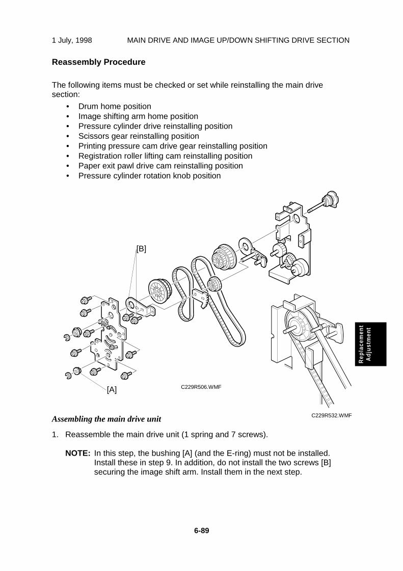
1 July, 1998 MAIN DRIVE AND IMAGE UP/DOWN SHIFTING DRIVE SECTION
6-89
Rep
lace
men
tA
dju
stm
ent
Reassembly Procedure
The following items must be checked or set while reinstalling the main drivesection:
• Drum home position• Image shifting arm home position• Pressure cylinder drive reinstalling position• Scissors gear reinstalling position• Printing pressure cam drive gear reinstalling position• Registration roller lifting cam reinstalling position• Paper exit pawl drive cam reinstalling position• Pressure cylinder rotation knob position
Assembling the main drive unit
1. Reassemble the main drive unit (1 spring and 7 screws).
NOTE: In this step, the bushing [A] (and the E-ring) must not be installed.Install these in step 9. In addition, do not install the two screws [B]securing the image shift arm. Install them in the next step.
C229R506.WMF
C229R532.WMF
[A]
[B]

MAIN DRIVE AND IMAGE UP/DOWN SHIFTING DRIVE SECTION 1 July, 1998
6-90
2. Tighten the two screws [A] toassemble the image shift armand image shift gear.
NOTE: Install the two screwstemporarily, since youmust retighten them instep 5.
3. Make sure that the plate on therear of the image shift arm isfirmly set on the bearing sleeve[B] as shown.
CAUTION: Once the two screws [A] are loosened, the rear plate of the imageshift arm easily slips off the bearing sleeve. Make sure that the rearplate is on the bearing sleeve properly also before installing themain drive unit on the machine rear frame in step 13.
4. Strongly push the shaft of the image shiftgear against the other gears, and firmly tighten the screw [C].
5. Similarly, tighten the two screws [E] while pushing the arm shaft against theother gears strongly.
NOTE: Step 4 and 5 are to remove play between the image shift gear and othergears. There must be no gear play between these gears. The screws areset through long holes [D]. Make sure that the screws reach the end of thelong hole when tightening them.
6. Make sure that the image shift gear smoothly moves along the drum drive gear.
C229R504.WMF
C229R508.WMF
C229R531.WMF
[B]
[C]
[D]
[D][E]
[A]

1 July, 1998 MAIN DRIVE AND IMAGE UP/DOWN SHIFTING DRIVE SECTION
6-91
Rep
lace
men
tA
dju
stm
ent
Setting the drum drive disk, image shifting arm, pressure cylinder drive disk, andscissors gear in their home positions
7. To set the drum drive disk in the home position, align the elongated hole [C] inthe drum drive disk straight downwards by turning the disk.
8. Set the image shift arm [A] in the home position. Align the hole in the upperplate [B] with the elongated hole in the image shift arm.
9. Align the hole in the pressure cylinder drive disk [E] with the hole in the sideplate of the drive unit [D], then install the bushing [F] (one E-ring).
NOTE: Before installing the bushing [F], make sure that the scissors gear [G]also meshes with the next gear. If the scissors gear is set incorrectly by180 degrees, the scissors gear will not mesh with that gear. (See OKand NG in the diagram above.)
C229R509.WMF
[C]
[A]
[B]
[D]
[E]
[F]
OK NG
[G]

MAIN DRIVE AND IMAGE UP/DOWN SHIFTING DRIVE SECTION 1 July, 1998
6-92
Installing the main drive unit on the machine rear frame
- From the paper exit side -
10. Remove the paper delivery unitand air knife unit. (See 6.12.1Paper Delivery Unit and Air KnifeFan Unit.)
11. Remove the job separator unit[A] (2 screws).
12. Remove the paper exit pawl.(See 6.12.5 Paper Exit PawlRemoval.)
13. While aligning andholding the pressurecylinder horizontally asshown, set the main driveunit so that the convexpoints of the pressurecylinder's drive disk [C]meet the concave pointsof the pressure cylinderdrive transmission disk[B] (made of whiteplastic).
NOTE: Hold the drum drivedisk, image shiftingarm, pressurecylinder drive disk,and scissors gear intheir home positionsas explained in step7, 8, and 9. Inaddition, make surethat the rear plate ison the bearing sleeveproperly as explainedin step 3.
C229R522.WMF
C229R023.WMF
[C]
[B]
[A]

1 July, 1998 MAIN DRIVE AND IMAGE UP/DOWN SHIFTING DRIVE SECTION
6-93
Rep
lace
men
tA
dju
stm
ent
14. Secure the main drive unit onthe machine rear frame (6screws).
15. Make sure that the image shift arm[B] is in the home position. Alignthe hole in the upper plate [A] withthe elongated hole in the imageshift arm (as explained in step 8).
16. Push the image up/down shiftdrive unit [C] against the imageshift arm sector gear, and securethe unit (3 screws, 3 connectors).
NOTE: 1) Ensure that the unit isset without any play.
2) Do not push on the unittoo strongly. Ensurethat the image shift armmoves smoothly aftersecuring the unit. If itdoes not, SC05-10 willbe displayed at powerup.
17. Install the main drive timing belt on the main motor shaft, and reassemble theparts of the main motor area. (Refer to steps 7 through 13 of the Disassemblyprocedure.)
C229R018.WMF
C229R024.WMF
[B]
[A]
[C]

MAIN DRIVE AND IMAGE UP/DOWN SHIFTING DRIVE SECTION 1 July, 1998
6-94
Fine adjustment using the special tools
NOTE: The tools are available as aservice part. The part number is#C229 9000 (three parts as aset).
18. Make sure that the drum drive diskis in the home position by settingthe drum drive securing tool [A].
NOTE: If the special tool is notavailable, align theelongated hole in the drumdrive disk [B] with the shaft[C] below it, as shown.
19. Install the drum unit in the machine.
20. Close the front cover, connect thepower plug, then turn on the mainswitch. The up/down image shifting mechanism will initialize.
NOTE: This procedure is needed to return the image shift arm to its homeposition. If the image shift arm is not returned to home position exactlyin this step, correct positioning for each main drive part will not beobtained.
21. Turn off the mainswitch, and disconnectthe power plug.
22. Remove the drum andagain set the drumdrive-securing tool [A].
23. From the rear, loosenthe two screws [D] toallow the pressurecylinder drive gear toturn freely.NOTE: Do not remove
the screws.
C229R081.WMF
C229R025.WMF
[A]
[B]
[C]
[D]
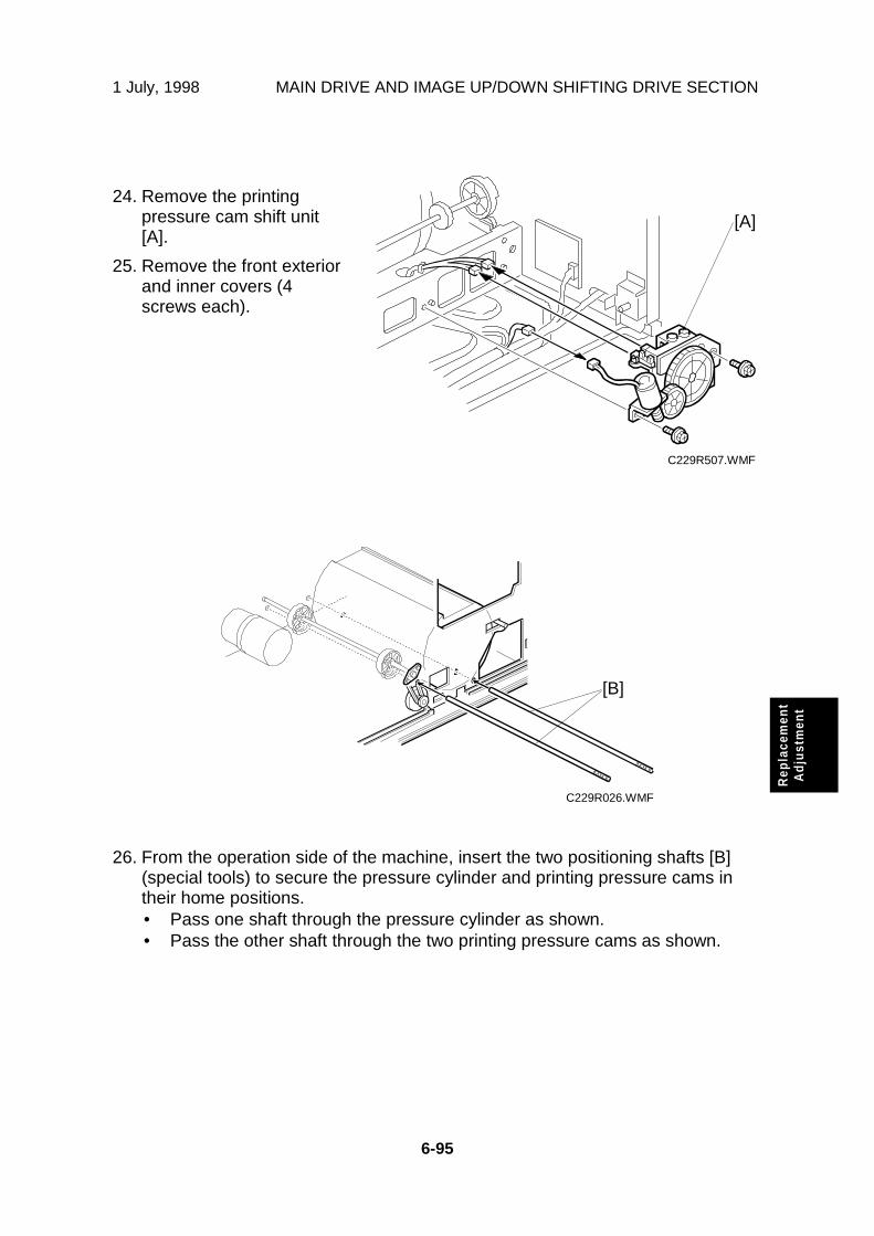
1 July, 1998 MAIN DRIVE AND IMAGE UP/DOWN SHIFTING DRIVE SECTION
6-95
Rep
lace
men
tA
dju
stm
ent
24. Remove the printingpressure cam shift unit[A].
25. Remove the front exteriorand inner covers (4screws each).
26. From the operation side of the machine, insert the two positioning shafts [B](special tools) to secure the pressure cylinder and printing pressure cams intheir home positions.• Pass one shaft through the pressure cylinder as shown.• Pass the other shaft through the two printing pressure cams as shown.
C229R507.WMF
C229R026.WMF
[B]
[A]

MAIN DRIVE AND IMAGE UP/DOWN SHIFTING DRIVE SECTION 1 July, 1998
6-96
27. Remove only the drumdrive-securing tool (leavethe two positioningshafts). Then turn themain motor [B] clockwiseby hand until the drumdrive disk [C] has turnedabout 10 degrees, asshown.
NOTE: Although themotor will not turnsmoothly sincethe drive issecured with thespecial tools, thisis normal.
28. Turn the main motor [A]counterclockwise, and setthe drum drive disk [B] inthe home position. (If thedisk is turned too much atthis point, reset from step26.)
CAUTION: These steps are needed to put gear play in the direction opposite tothe printing direction. Make sure to turn the main motor by hand inthe above order (steps 27 and 28). If the motor is turned in wrongorder, the main drive will turn slightly when the two shafts (specialtools) are removed. If you turned it in the wrong order, return tostep 27 then do step 28.
C229R535.WMF
C229R536.WMF
[A]
[B]
[B]
[C]

1 July, 1998 MAIN DRIVE AND IMAGE UP/DOWN SHIFTING DRIVE SECTION
6-97
Rep
lace
men
tA
dju
stm
ent
29. Set the drum drive-securing tool once again. (See step 18.)CAUTION: Do not turn the drum drive disk by force while setting the tool. If you
turned the disk, return to step 27 then do step 28.
30. Secure the pressure cylinder drive gear [A] (2 screws).CAUTION: Don’t turn the gear by force while securing it.
31. Install the printing pressure cam drive gear and firmly tighten the 2 screws [B].
NOTE: 1) To remove gear play, secure the cam drive gear while turning itcounterclockwise (as viewed from the rear).
2) Secure the cam drive gear by tightening the two screws in themiddle of the curved oval holes. This allows for the maximumadjustable range for later repositioning of the gear.
C229R079.WMF[B]
[A]

MAIN DRIVE AND IMAGE UP/DOWN SHIFTING DRIVE SECTION 1 July, 1998
6-98
Finishing
32. Install the registration roller lifting cam [C]. (See 6.9.9 Registration Roller LiftingCam Position Adjustment for the correct position of the cam.)
33. Install the pulley cover [B] and bracket [A].
34. Install the exit pawl, and adjust the paper exit pawl drive timing. (See 6.12.7Paper Exit Pawl Drive Timing Adjustment.)
35. Adjust the pressure cylinder rotation knob. (See 6.11.3 Pressure CylinderRotation Knob Adjustment.)
36. Remove all special tools (the drum drive-securing tool and two positioningshafts).
37. Adjust the gap between the exit pawl and the drum. Also adjust the gapbetween the paper scraper and the pressure cylinder. (See 6.12.6 GapAdjustment between Paper Pick-off Plate and Pressure Cylinder and 6.12.8Gap Adjustment between Exit Pawl and Drum.)
C229R501.WMF
[A]
[B]
[C]

1 July, 1998 MAIN DRIVE AND IMAGE UP/DOWN SHIFTING DRIVE SECTION
6-99
Rep
lace
men
tA
dju
stm
ent
Copy Image Check Procedure after Main Drive and Image Up/DownShifting Drive Section Re-assembly
When the main drive mechanism is disassembled and assembled, the imageposition on copies may fluctuate due to play in the drive components.
Whenever you disassemble the main drive mechanism, you must check thefollowing items for the copy quality:
When the image position on copies is not constant• Check the pressure cylinder position.
Use the positioning shaft (a special tool) to check if the position of thepressure cylinder is correct. See steps 26 through 30 in "ReassemblyProcedure" of 6.11.2 Main Drive Mechanism (Main Drive Timing Belt).
When the leading edge margin of copies (10 mm) is not constant• Check the position of the printing pressure cams.
Use the positioning shaft (a special tool) to check if the cam position iscorrect. See steps 26 through 31 in "Reassembly Procedure" of 6.11.2 MainDrive Mechanism (Main Drive Timing Belt).
• Check if you followed steps 18 through 21 in "Reassembly Procedure" of6.11.2 Main Drive Mechanism (Main Drive Timing Belt).
Other procedures if copy image problems are still detected• Check the image up/down shift drive unit position.
See 6.11.6 Image Up/Down Shift Drive Unit Position Adjustment. Also, see6.11.5 Image Up/Down Shift Worm-gear Position Adjustment.
• Check the image shift gear play.See steps 2 through 6 in "Reassembly Procedure" of 6.11.2 Main DriveMechanism (Main Drive Timing Belt).
• Check the scissors gear position.See step 9 in "Reassembly Procedure" of 6.11.2 Main Drive Mechanism(Main Drive Timing Belt). Also, see 6.11.4 Scissors Gear PositionAdjustment.

MAIN DRIVE AND IMAGE UP/DOWN SHIFTING DRIVE SECTION 1 July, 1998
6-100
6.11.3 PRESSURE CYLINDER ROTATION KNOB ADJUSTMENT
1. Set the drum drive securing tool [B] (a special tool) as shown to hold the drumdrive at home position.NOTE: If the special tool is not available, align the long hole of the drum drive
disk [A] exactly with the shaft below it.
2. Loosen two screws [C] so that the pulley [D] freely turns.
3. Turn the timing belt [E] by hand until the triangle mark on the indicator diskmeets the center division. (When the indicator disk is in the correct position, thehole in the disk and the two holes in the bracket are in line, as shown [F].
4. Retighten the two screws [C] to secure the pulley in position.
C229R011.WMF
1[A]
[D]
3
2
[B]
[C]
[E]
[F]

1 July, 1998 MAIN DRIVE AND IMAGE UP/DOWN SHIFTING DRIVE SECTION
6-101
Rep
lace
men
tA
dju
stm
ent
6.11.4 SCISSORS GEAR POSITION ADJUSTMENT
PURPOSE: If the position of the scissors gear is not correct, the paper feedregistration will vary.
1. Loosen the lock nut [B].
2. Tighten the screw, so that the gear meshes on both gears are aligned asshown [A].
3. Turn the screw fully counterclockwise circle to loosen it, as shown [C].
4. Holding the screw, tighten the lock nut [B].
C229R505.WMF
[A]
[B]
[C]

MAIN DRIVE AND IMAGE UP/DOWN SHIFTING DRIVE SECTION 1 July, 1998
6-102
6.11.5 IMAGE UP/DOWN SHIFT WORM-GEAR POTISIONADJUSTMENT
Fully push up the worm gear [A], and push down the worm gear shaft [B]. Whileholding them together, secure with the 2 set screws.
C229R027.WMF
[A]
[B]

1 July, 1998 MAIN DRIVE AND IMAGE UP/DOWN SHIFTING DRIVE SECTION
6-103
Rep
lace
men
tA
dju
stm
ent
6.11.6 IMAGE UP/DOWN SHIFT DRIVE UNIT POSITIONADJUSTMENT
PURPOSE: To take out any play while using the image up/down shiftingfunction.
1. Set the image shift arm [B] in the home position. Align the hole in the upperplate with the elongated hole in the image shift arm [A].
2. Push the image up/down shift drive unit [C] against the image shift arm sectorgear, and secure the unit (3 screws, 3 connectors).
NOTE: 1) Set the arm without play in the vertical direction of the image shiftarm.
2) Do not push too strongly. Check if the image shift arm movessmoothly after securing the unit. If it does not, SC05-10 will light atpower on.
C229R024.WMF
[A]
[B]
[C]

PAPER DELIVERY SECTION 1 July, 1998
6-104
6.12 PAPER DELIVERY SECTION
6.12.1 PAPER DELIVERY UNIT AND AIR KNIFE FAN UNIT
1. Turn off the main switch.
2. Remove the paper delivery cover [A] (4 screws).
3. Remove the paper delivery unit [B] (2 screws, 3 connectors, ground wire, knob,belt).
4. Remove the air knife fan unit [C] (2 screws, 1 connector).
C229R515.WMF
C229R520.WMF
C229R521.WMF
[A]
[B]
[C]

1 July, 1998 PAPER DELIVERY SECTION
6-105
Rep
lace
men
tA
dju
stm
ent
6.12.2 PAPER TRANSPORT BELT REMOVAL
First, remove the paper delivery unit (see 6.12.1 Paper Delivery Unit and Air KnifeFan Unit), then remove the paper pick-off plate from the unit (4 screws).
A: Driven roller shaft
B: Upper unit
C: Paper guide wings
D: Drive roller shaft
E: Transport belts
CAUTION: 1) When reassembling, the actuator [F] for the wing upper andlower position sensors must be positioned between the sensors.
2) Both ends of the driven roller shaft [G] have a milled flat face.When reassembling, make sure that the ends are set firmly intothe cutouts in the base.
C229R012.WMF
[C]
[D]
[F]
[G]
[A]
[E]
[B]
[C]

PAPER DELIVERY SECTION 1 July, 1998
6-106
6.12.3 PAPER EXIT SENSOR REMOVAL
First, remove the paper delivery unit. (See 6.12.1 Paper Delivery Unit and Air KnifeFan Unit.)
A: Vacuum fan unit (4 screws)
B: Paper exit sensor (1 screw, 1 connector)
C229R013.WMF
[A]
[B]

1 July, 1998 PAPER DELIVERY SECTION
6-107
Rep
lace
men
tA
dju
stm
ent
6.12.4 VACUUM MOTOR REMOVAL
First, remove the paper delivery unit. (See 6.12.1 Paper Delivery Unit and Air KnifeFan Unit.)
A: Vacuum motor (2 screws)
C229R518.WMF
[A]

PAPER DELIVERY SECTION 1 July, 1998
6-108
6.12.5 PAPER EXIT PAWL REMOVAL
1. Remove the drum unit.
2. Remove the paper exit pawl [A] (1 screw).
C229R519.WMF
[A]

1 July, 1998 PAPER DELIVERY SECTION
6-109
Rep
lace
men
tA
dju
stm
ent
6.12.6 GAP ADJUSTMENT BETWEEN PAPER PICK-OFF PLATEAND PRESSURE CYLINDER
PURPOSE: To ensure smooth paper feed to the paper delivery unit
1. Remove the drum.
2. Apply the printing pressure as follows. (Push the pressure cylinder up to theprinting position.)
1) Access SP 5-121, and select “ON” for the printing pressure release solenoid.2) While the solenoid is on, turn the cylinder half way round by hand.3) Leave SP mode.
3. Adjust the clearance between the paper pick-off plate [A] and the surface of thepressure cylinder until it is 1 ± 0.3 mm (loosen the 4 screws).
CAUTION: Be sure to perform this adjustment after pushing the pressure cylinderup to the printing position. If the gap is adjusted with the pressurecylinder in the non-printing position, the paper pick-off plate willdamage the pressure cylinder when the printing pressure is appliedand the pressure cylinder is pushed up, because the gap will be toosmall.
C229R014.WMF
1 ± 0.3 mm
[A]

PAPER DELIVERY SECTION 1 July, 1998
6-110
6.12.7 PAPER EXIT PAWL DRIVE TIMING ADJUSTMENT
PURPOSE: To ensure smooth paper feed, and to ensure that the exit pawl doesnot touch the master clamper on the drum.
NOTE: You must adjust this after the main drive belt is replaced.
1. Remove the drum.
2. Remove the paper delivery unit. (See 6.12.1 Paper Delivery Unit and Air KnifeFan Unit.)
3. Make sure that the drum drive disk is in the home position.
NOTE: Normally, the disk is in the home position after the drum is removed. Ifnecessary, set the drum securing tool [A] to make sure that the drumdrive disk is in the home position. (If the special tool is not available,align the long positioning hole in the drum drive disk exactly with theshaft [C] below it as shown.)
4. Make sure that the positioning holes in the rear frame and the drive gear [B] arein line as shown [C].
5. If the holes are in line, the paper exit pawl drive timing is OK. If they are not,remove the gear [B] and reinstall it so that the holes are in line.
C229R015.WMF
[A]
[B]
[C]

1 July, 1998 PAPER DELIVERY SECTION
6-111
Rep
lace
men
tA
dju
stm
ent
6.12.8 GAP ADJUSTMENT BETWEEN EXIT PAWL AND DRUM
PURPOSE: To ensure that the paper is delivered without paper wrap or damage.
1. Turn the main drive manually, so that the bearing [A] of the exit pawl arm [C]rides on the low point of the cam.
NOTE: Use the main drive rotation knob to turn the main drive.
2. By moving the adjusting plate [B], adjust the clearance [C] between the drumand the top of the exit pawl until it becomes 1 ± 0.5 mm.
C229R016.WMF
[A]
[B]
[C]

1 July, 1998
7-1
P-t
o-P
7. POINT TO POINT DIAGRAM
• Location Map• Section A• Section B• Section C• Section D• Section E• Section F
NOTE: The symbols used in the diagrams are as follows:
PP2.WMF

1 July, 1998
7-2
Location Map
C229S500.WMF
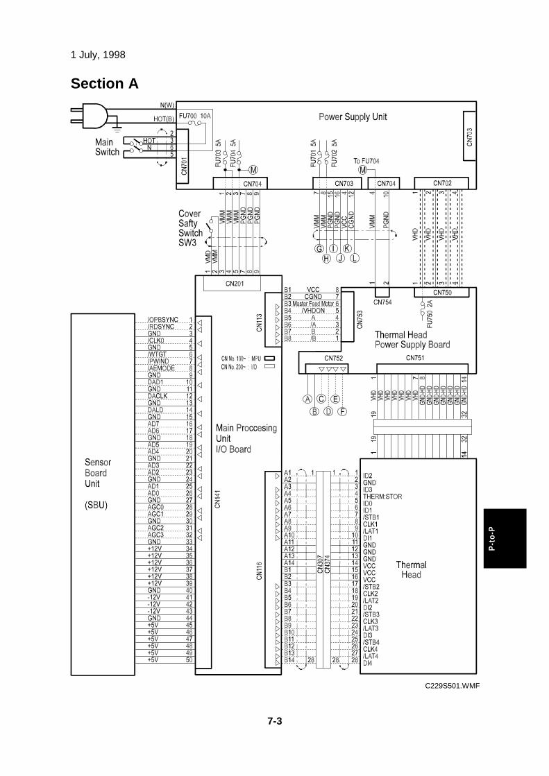
1 July, 1998
7-3
P-t
o-P
Section A
C229S501.WMF

1 July, 1998
7-4
Section B
C229S502.WMF

1 July, 1998
7-5
P-t
o-P
Section C
C229S503.WMF

1 July, 1998
7-6
Section D
C229S504.WMF

1 July, 1998
7-7
P-t
o-P
Section E
C229S505.WMF

1 July, 1998
7-8
Section F
C229S506.WMF
1. OVERALL INFORMATION 1-1...........................................1.1 SPECIFICATIONS 1-1....................................................1.2 GUIDE TO COMPONENTS AND THEIR 1-5................
1.2.1 MACHINE EXTERIOR 1-5...................................................1.3 MACHINE INTERIOR 1-6..............................................
1.3.1 OPERATION PANEL 1-8.....................................................1.3.2 INDICATORS 1-10.................................................................
1.4 PRINTING PROCESS OVERVIEW 1-11.........................1.5 MECHANICAL COMPONENT LAYOUT 1-12.................1.6 ELECTRICAL COMPONENT LAYOUT 1-13...................
1.6.1 PRINTED CIRCUIT BOARD LAYOUT 1-13..........................1.6.2 SCANNER SECTION 1-14....................................................1.6.3 PAPER FEED SECTION 1-14...............................................1.6.4 MASTER EJECT, PRESSURE CYLINDER, AND 1-15.........1.6.5 PAPER DELIVERY SECTION 1-16.......................................1.6.6 MASTER MAKING UNIT 1-16...............................................1.6.7 DRUM UNIT 1-17...................................................................1.6.8 TABLES OF ELECTRICAL COMPONENTS 1-18................
1.7 DRIVE LAYOUT 1-22.......................................................1.7.1 OVERVIEW 1-22...................................................................1.7.2 MAIN DRIVE 1-23..................................................................
2. DETAILED SECTION DESCRIPTIONS 2-1........................2.1 SCANNER AND OPTICS 2-1........................................
2.1.1 OVERVIEW 2-1...................................................................2.1.2 SCANNER DRIVE 2-2.........................................................2.1.3 ORIGINAL SIZE DETECTION IN PLATEN MODE 2-3........
2.2 IMAGE-PROCESSING 2-5.............................................2.2.1 OVERVIEW 2-5...................................................................2.2.2 AUTO BACKGROUND CORRECTION 2-6.........................2.2.3 AUTO SHADING 2-7...........................................................2.2.4 FILTERING AND MAIN SCAN MAGNIFICATION/R 2-8.....2.2.5 BINARY PROCESSING 2-10................................................2.2.6 OPTIONAL MEMORY BOARD 2-11......................................2.2.7 THERMAL HEAD 2-12...........................................................
2.3 MASTER EJECT 2-14.....................................................2.3.1 OVERVIEW 2-14...................................................................2.3.2 MASTER EJECT MECHANISM 2-15....................................2.3.3 PRESSURE PLATE DRIVE MECHANISM 2-22...................
2.4 MASTER FEED 2-27.......................................................2.4.1 OVERVIEW 2-27...................................................................2.4.2 MASTER SET MECHANISM 2-28.........................................2.4.3 MASTER MAKING AND FEED MECHANISM 2-30...............2.4.4 WRAPPING THE MASTER AROUND DRUM 2-33..............2.4.5 MASTER MAKING UNIT SLIDE-OUT MECHANISM 2-38....2.4.6 OPENING DOOR FOR MISFED MASTER 2-38...................
2.5 DRUM 2-39.......................................................................

2.5.1 OVERVIEW 2-39...................................................................2.5.2 INK SUPPLY AND KNEADING MECHANISM 2-40..............2.5.3 DRUM SHIFT MECHANISM FOR IMAGE 2-47.....................2.5.4 DRUM SET MECHANISM 2-48.............................................2.5.5 DRUM DRIVE MECHANISM 2-49.........................................2.5.6 MASTER DETECTION 2-50..................................................
2.6 PAPER FEED 2-51..........................................................2.6.1 OVERVIEW 2-51...................................................................2.6.2 PAPER FEED MECHANISM 2-52.........................................2.6.3 PAPER FEED/SEPARATION PRESSURE 2-54...................2.6.4 PAPER REGISTRATION MECHANSM 2-58.........................2.6.5 PAPER FEED CONTROL MECHANISM 2-61......................2.6.6 PAPER TABLE ANGLE ADJUSTMENT 2-62........................2.6.7 PAPER TABLE OPEN DETECTION 2-63.............................2.6.8 PAPER TABLE UP/DOWN MECHANISM 2-64.....................2.6.9 PAPER SIDE FENCE MECHANISM 2-66.............................2.6.10 PAPER SIZE AND PAPER END DETECTIONS 2-67.........
2.7 PRINTING AND PRESSURE CYLINDER 2-68................2.7.1 OVERVIEW 2-68...................................................................2.7.2 PAPER CLAMPING 2-69.......................................................2.7.3 PRINTING PRESSURE MECHANISM 2-71..........................2.7.4 PRINTING PRESSURE CAM SHIFTING FOR 2-72..............2.7.5 PAPER FEED CONTROL MECHANISM 2-73......................2.7.6 PRESSURE CYLINDER DRIVE MECHANISM 2-74.............
2.8 PAPER DELIVERY 2-76..................................................2.8.1 OVERVIEW 2-76...................................................................2.8.2 PAPER SEPARATION FROM THE DRUM 2-77...................2.8.3 PAPER DELIVERY WING MECHANISM 2-78......................2.8.4 PAPER DELIVERY TABLE MECHANISM 2-79....................2.8.5 PAPER DELIVERY JAM SENSORS 2-80.............................2.8.6 PAPER DELIVERY UNIT DRIVE MECHANISM 2-81............2.8.7 JOB SEPARATION MECHANISM 2-82.................................
2.9 IMAGE UP/DOWN SHIFTING 2-84.................................2.9.1 OVERVIEW 2-84...................................................................2.9.2 IMAGE UP/DOWN SHIFTING MECHANISM 2-85................
3. INSTALLATION 3-1..............................................................3.1 INSTALLATION REQUIREMENTS 3-1.........................
3.1.1 REQUIRED ENVIRONMENTAL CONDITIONS 3-1............3.1.2 ENVIRONMENTS TO AVOID 3-1........................................3.1.3 POWER CONNECTION 3-1................................................3.1.4 ACCESS TO MACHINE: 3-2...............................................
3.2 INSTALLATION PROCEDURE 3-3...............................3.2.1 MAIN BODY 3-3...................................................................3.2.2 AUTO DOCUMENT FEEDER (OPTION) 3-10......................3.2.3 INTERFACE BOARD (OPTION) 3-16..................................3.2.4 COLOR DRUM (OPTION) 3-17.............................................
4. SERVICE TABLES 4-1.........................................................

4.1 SERVICE REMARKS 4-1..............................................4.1.1 SCANNER SECTION 4-1...................................................4.1.2 MASTER EJECT SECTION 4-1..........................................4.1.3 MASTER FEED SECTION 4-1............................................4.1.4 PAPER FEED SECTION 4-2...............................................4.1.5 DRUM AND DRUM DRIVE SECTION 4-2...........................4.1.6 MAIN DRIVE SECTION 4-3.................................................4.1.7 ELECTRICAL COMPONENTS 4-3......................................
4.2 DIP SW, LED, VR, TP, AND FUSE TABLES 4-4..........4.2.1 TEST POINTS 4-4...............................................................4.2.2 DIP SWITCHES 4-4.............................................................4.2.3 POTENTIOMETERS 4-4.....................................................4.2.4 LED’S 4-5.............................................................................4.2.5 FUSES 4-5...........................................................................
4.3 SERVICE CALL CODES 4-6.........................................4.4 SPECIAL TOOLS 4-14.....................................................4.5 SERVICE PROGRAM MODE 4-15..................................
4.5.1 ACCESS PROCEDURE 4-15................................................4.5.2 SERVICE PROGRAM TABLE 4-17.......................................4.5.3 CLEARING THE FACTORY SETTINGS (SP7-1) 4-49..........4.5.4 LOAD PROGRAM (SP8-20) 4-50..........................................4.5.5 USER TOOLS 4-51................................................................
5. PREVENTIVE MAINTENANCE 5-1......................................5.1 MAINTENANCE TABLE 5-1...........................................
6. REPLACEMENT AND ADJUSTMENT 6-1.........................6.1 EXTERIOR 6-1...............................................................
6.1.1 EXPOSURE GLASS, OPERATION PANEL, AND 6-1........6.1.2 REAR AND LEFT COVERS 6-2..........................................6.1.3 FRONT DOOR, AND RIGHT FRONT AND RIGHT 6-3.......6.1.4 INNER COVER AND KNOB COVER 6-4............................
6.2 COPY IMAGE ADJUSTMENT 6-5.................................6.2.1 LEADING EDGE REGISTRATION ADJUSTMENT 6-5.......6.2.2 SIDE-TO-SIDE REGISTRATION ADJUSTMENT 6-6..........6.2.3 VERTICAL MAGNIFICATION ADJUSTMENT 6-7...............
6.3 MPU AND I/O BOARD REPLACEMENT 6-8.................6.4 MPU AND PSU OPENING PROCEDURES 6-9............6.5 SCANNER UNIT 6-10.......................................................
6.5.1 LENS COVER 6-10................................................................6.5.2 SCANNER FRAME 6-11........................................................6.5.3 ORIGINAL SIZE SENSOR AND LENS 6-12.........................6.5.4 XENON LAMP 6-13...............................................................6.5.5 SCANNER H. P. SENSOR/PLATEN COVER 6-14...............6.5.6 SCANNER MOTOR 6-15.......................................................6.5.7 SCANNER WIRE 6-16...........................................................6.5.8 SENSOR BOARD UNIT CALIBRATION 6-18.......................
6.6 MASTER EJECT SECTION 6-19....................................

6.6.1 MASTER EJECT ROLLER UNIT 6-19...................................6.6.2 MASTER EJECT DRIVE UNIT 6-20......................................6.6.3 MASTER EJECT SENSOR ADJUSTMENT 6-22..................6.6.4 REASSEMBLING THE MASTER PICK-UP 6-23...................
6.7 MASTER FEED SECTION 6-24......................................6.7.1 MASTER MAKING UNIT REMOVAL 6-24.............................6.7.2 MASTER SET ROLLER AND PLATEN ROLLER 6-25.........6.7.3 THERMAL HEAD 6-27...........................................................6.7.4 SENSORS, MOTORS, AND CUTTER IN THE 6-28..............6.7.5 MASTER VACUUM FAN POSITIONING 6-38......................6.7.6 THERMAL HEAD VOLTAGE ADJUSTMENT 6-39................6.7.7 MASTER END SENSOR ADJUSTMENT 6-40......................6.7.8 MASTER EDGE SENSOR ADJUSTMENT 6-41...................6.7.9 PLATEN RELEASE CAM ADJUSTMENT 6-43.....................6.7.10 MASTER FEED MYLAR POSITIONING 6-44.....................
6.8 DRUM 6-45.......................................................................6.8.1 DRUM CLOTH SCREEN 6-45...............................................6.8.2 DRUM MASTER CLAMPER AND METAL SCREEN 6-47....6.8.3 MOTORS AND SENSORS IN THE DRUM 6-49...................6.8.4 FIRST DRUM MASTER SENSOR ADJUSTMENT 6-52.......6.8.5 SECOND DRUM MASTER SENSOR ADJUSTMENT 6-53..6.8.6 INK ROLLER GAP ADJUSTMENT 6-55................................6.8.7 INK DETECTION ADJUSTMENT 6-56..................................
6.9 PAPER FEED SECTION 6-57.........................................6.9.1 PAPER TABLE UNIT 6-57.....................................................6.9.2 PAPER FEED ROLLER, PICK-UP ROLLER, AND 6-58.......6.9.3 PAPER WIDTH DETECTION BOARD 6-59..........................6.9.4 PAPER HEIGHT SENSOR 6-59............................................6.9.5 FEED PRESSURE DETECTION BOARD 6-60.....................6.9.6 PAPER REGISTRATION AND FEED TIMING 6-61..............6.9.7 LOWER REGISTRATION ROLLER 6-65..............................6.9.8 REGISTRATION ROLLER LIFTING CAM REMOVAL 6-66..6.9.9 REGISTRATION ROLLER LIFTING CAM 6-67.....................6.9.10 PAPER TABLE HEIGHT ADJUSTMENT 6-68....................6.9.11 TIMING BELT TENSION ADJUSTMENT FOR 6-69............6.9.12 TIMING BELT TENSION ADJUSTMENT FOR 6-70............6.9.13 PAPER FEED AND SEPARATION PRESSURE 6-71........6.9.14 PAPER FEED LENGTH ADJUSTMENT 6-72.....................
6.10 PRINTING SECTION 6-74..............................................6.10.1 PRESSURE CYLINDER 6-74..............................................6.10.2 FEED START SENSOR AND FEED ENCODER 6-79........6.10.3 PRINTING PRESSURE ADJUSTMENT 6-80......................6.10.4 PRINTING PRESSURE RELEASE ARM GAP 6-81............
6.11 MAIN DRIVE AND IMAGE UP/DOWN 6-82...................6.11.1 MAIN MOTOR 6-82.............................................................6.11.2 MAIN DRIVE MECHANISM (MAIN DRIVE TIMING 6-85....6.11.3 PRESSURE CYLINDER ROTATION KNOB 6-100...............6.11.4 SCISSORS GEAR POSITION ADJUSTMENT 6-101............6.11.5 IMAGE UP/DOWN SHIFT WORM-GEAR 6-102...................

6.11.6 IMAGE UP/DOWN SHIFT DRIVE UNIT 6-103......................6.12 PAPER DELIVERY SECTION 6-104................................
6.12.1 PAPER DELIVERY UNIT AND AIR KNIFE FAN 6-104.........6.12.2 PAPER TRANSPORT BELT REMOVAL 6-105.....................6.12.3 PAPER EXIT SENSOR REMOVAL 6-106.............................6.12.4 VACUUM MOTOR REMOVAL 6-107....................................6.12.5 PAPER EXIT PAWL REMOVAL 6-108..................................6.12.6 GAP ADJUSTMENT BETWEEN PAPER 6-109....................6.12.7 PAPER EXIT PAWL DRIVE TIMING 6-110...........................6.12.8 GAP ADJUSTMENT BETWEEN EXIT PAWL 6-111.............
7. POINT TO POINT DIAGRAM 7-1........................................Location Map 7-2..................................................................Section A 7-3........................................................................Section B 7-4........................................................................Section C 7-5........................................................................Section D 7-6........................................................................Section E 7-7........................................................................Section F 7-8.........................................................................