Embed Size (px)
Citation preview
© 2005 American Honda Motor Co., Inc. - All Rights Reserved. All 28631-31200 (0510) 1 of 13
INSTALLATIONINSTRUCTIONS
Accessory Application Publications No.
Issue Date
OCT 2005
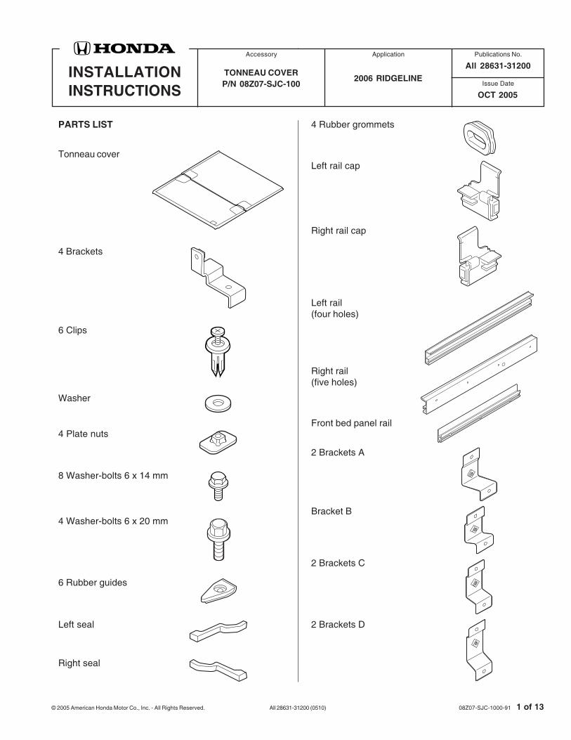
2006 RIDGELINETONNEAU COVERP/N 08Z07-SJC-100
08Z07-SJC-1000-91
PARTS LIST
Tonneau cover
4 Brackets
6 Clips
Washer
4 Plate nuts
8 Washer-bolts 6 x 14 mm
4 Washer-bolts 6 x 20 mm
6 Rubber guides
Left seal
Right seal
4 Rubber grommets
Left rail cap
Right rail cap
Left rail(four holes)
Right rail(five holes)
Front bed panel rail
All 28631-31200
2 Brackets A
Bracket B
2 Brackets C
2 Brackets D
2 of 13 All 28631-31200 (0510) © 2005 American Honda Motor Co., Inc. - All Rights Reserved.
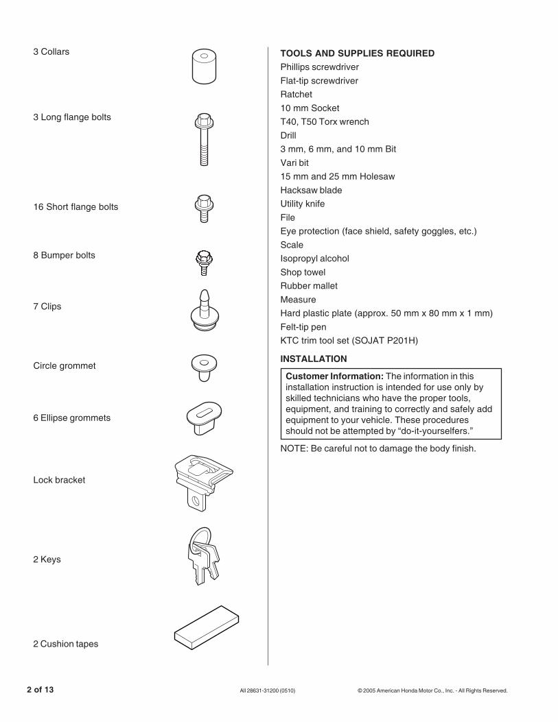
3 Collars
3 Long flange bolts
16 Short flange bolts
8 Bumper bolts
7 Clips
Circle grommet
6 Ellipse grommets
Lock bracket
2 Keys
TOOLS AND SUPPLIES REQUIREDPhillips screwdriverFlat-tip screwdriverRatchet10 mm SocketT40, T50 Torx wrenchDrill3 mm, 6 mm, and 10 mm BitVari bit15 mm and 25 mm HolesawHacksaw bladeUtility knifeFileEye protection (face shield, safety goggles, etc.)ScaleIsopropyl alcoholShop towelRubber malletMeasureHard plastic plate (approx. 50 mm x 80 mm x 1 mm)Felt-tip penKTC trim tool set (SOJAT P201H)
INSTALLATION
Customer Information: The information in thisinstallation instruction is intended for use only byskilled technicians who have the proper tools,equipment, and training to correctly and safely addequipment to your vehicle. These proceduresshould not be attempted by “do-it-yourselfers.”
NOTE: Be careful not to damage the body finish.
2 Cushion tapes

© 2005 American Honda Motor Co., Inc. - All Rights Reserved. All 28631-31200 (0510) 3 of 13
6. While wearing eye protection, drill a 3 mm holethrough eight marked locations on the inside of thefront bed panel.
FRONT BEDPANEL(Inside)
MARKS (8)
DRILL (3 mm drill bit)
3920131T
3929032H
FRONT BEDPANEL
TORXBOLTS (6)
4610041H
TORXBOLT(T50)
LEFT FRONT UPPERTIE-DOWN HOOK
4611010H
FRONT BEDPANEL
UPPER HOLE
STEP DRILLExpand the holesto 1 in. (25 mm).
Top edge
1. Make sure you have the anti-theft code for theradio, then write down the radio station presets.
2. Disconnect the negative cable from the battery.
3. Remove the left front upper tie-down hook (twotorx bolts). Remove the right front upper tie-downhook (two torx bolts).
4. Remove the front bed panel (six torx bolts).
5. While wearing eye protection, enlarge the threeupper holes in the front bed panel using a 1 in.(25 mm) step drill. Remove all burrs from theedges of the holes with a file.
4 of 13 All 28631-31200 (0510) © 2005 American Honda Motor Co., Inc. - All Rights Reserved.
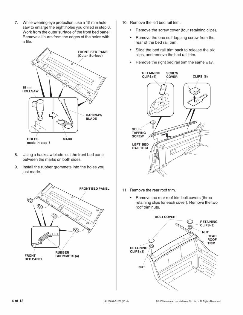
7. While wearing eye protection, use a 15 mm holesaw to enlarge the eight holes you drilled in step 6.Work from the outer surface of the front bed panel.Remove all burrs from the edges of the holes witha file.
8. Using a hacksaw blade, cut the front bed panelbetween the marks on both sides.
9. Install the rubber grommets into the holes youjust made.
3920141T
15 mmHOLESAW
FRONT BED PANEL(Outer Surface)
HOLESmade in step 6
MARK
HACKSAWBLADE
3920151T
FRONT BED PANEL
RUBBERGROMMETS (4)FRONT
BED PANEL
10. Remove the left bed rail trim.
• Remove the screw cover (four retaining clips).
• Remove the one self-tapping screw from therear of the bed rail trim.
• Slide the bed rail trim back to release the sixclips, and remove the bed rail trim.
• Remove the right bed rail trim the same way.
11. Remove the rear roof trim.
• Remove the rear roof trim bolt covers (threeretaining clips for each cover). Remove the tworoof trim nuts.
4D19051H
BOLT COVERRETAININGCLIPS (3)
NUTREARROOFTRIM
NUT
RETAININGCLIPS (3)
3926071H
LEFT BEDRAIL TRIM
SELF-TAPPINGSCREW
SCREWCOVER
RETAININGCLIPS (4) CLIPS (6)
© 2005 American Honda Motor Co., Inc. - All Rights Reserved. All 28631-31200 (0510) 5 of 13
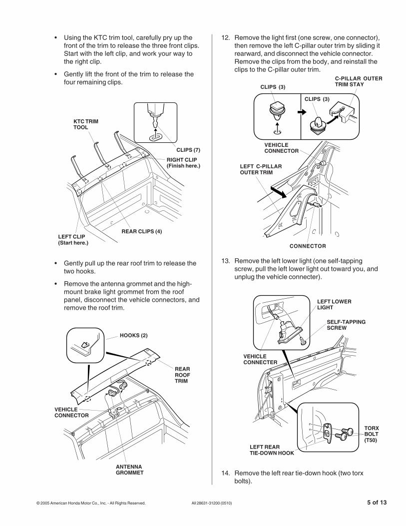
• Using the KTC trim tool, carefully pry up thefront of the trim to release the three front clips.Start with the left clip, and work your way tothe right clip.
• Gently lift the front of the trim to release thefour remaining clips.
• Gently pull up the rear roof trim to release thetwo hooks.
• Remove the antenna grommet and the high-mount brake light grommet from the roofpanel, disconnect the vehicle connectors, andremove the roof trim.
3926062H
SELF-TAPPINGSCREW
VEHICLECONNECTER
LEFT LOWERLIGHT
TORXBOLT(T50)
LEFT REARTIE-DOWN HOOK
12. Remove the light first (one screw, one connector),then remove the left C-pillar outer trim by sliding itrearward, and disconnect the vehicle connector.Remove the clips from the body, and reinstall theclips to the C-pillar outer trim.
13. Remove the left lower light (one self-tappingscrew, pull the left lower light out toward you, andunplug the vehicle connecter).
14. Remove the left rear tie-down hook (two torxbolts).
4D19062H
KTC TRIMTOOL
CLIPS (7)
LEFT CLIP(Start here.)
REAR CLIPS (4)
RIGHT CLIP(Finish here.)
HOOKS (2)
REARROOFTRIM
VEHICLECONNECTOR
ANTENNAGROMMET
4804024H
4611021H
CLIPS (3)
CLIPS (3)
C-PILLAR OUTERTRIM STAY
LEFT C-PILLAROUTER TRIM
VEHICLECONNECTOR
CONNECTOR
6 of 13 All 28631-31200 (0510) © 2005 American Honda Motor Co., Inc. - All Rights Reserved.
3920161T
LEFT BED PANEL(Inside)
MARKS (8)
DRILL (3 mm bit)
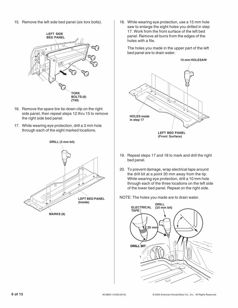
18. While wearing eye protection, use a 15 mm holesaw to enlarge the eight holes you drilled in step17. Work from the front surface of the left bedpanel. Remove all burrs from the edges of theholes with a file.
The holes you made in the upper part of the leftbed panel are to drain water.
3920171T
15 mm HOLESAW
LEFT BED PANEL(Front Surface)
HOLES madein step 17
15. Remove the left side bed panel (six torx bolts).
3926021H
LEFT SIDEBED PANEL
TORXBOLTS (6)(T40)
16. Remove the spare tire tie-down clip on the rightside panel, then repeat steps 12 thru 15 to removethe right side bed panel.
17. While wearing eye protection, drill a 3 mm holethrough each of the eight marked locations.
19. Repeat steps 17 and 18 to mark and drill the rightbed panel.
20. To prevent damage, wrap electrical tape aroundthe drill bit at a point 30 mm away from the tip.While wearing eye protection, drill a 10 mm holethrough each of the three locations on the left sideof the lower bed panel. Repeat on the right side.
NOTE: The holes you made are to drain water.
DRILL (10 mm bit)
DRILL BIT
ELECTRICAL TAPE
DRILL BIT
30 mm

© 2005 American Honda Motor Co., Inc. - All Rights Reserved. All 28631-31200 (0510) 7 of 13
3920180T
LEFT SEAL
ADHESIVEBACKING
LEFT BED PANEL
21. Using isopropyl alcohol on a shop towel, clean theleft bed panel where the left seal will attach.
22. Remove the adhesive backing from the left seal,and attach it to the left bed panel as shown.
3930021H
SHORT FLANGEBOLTS (8)
BRACKET ABRACKET B
BRACKET C
BRACKET D
3930031H
BRACKET A
BRACKET CBRACKET D
SHORT FLANGEBOLTS (6)
23. Install the right seal to the right side bed panel thesame way.
24. Position bracket A, B, C and D on the left vehiclepanel, and install them with two short flange boltsfor each bracket.
25. Position bracket A, C and D on the right vehiclepanel, and install them with two short flange boltsfor each bracket.
4D20510K
GROMMET(Discard.)
CIRCLEGROMMET
ELLIPSEGROMMETS (6)
GROMMET (6)(Discard.)
26. Reinstall the left and right bed panels.
27. Reinstall the right and left C-pillar outer trims.
28. Remove and discard the grommets from the roofpanel, and install the ellipse grommets and onecircle grommet to the roof panel.

8 of 13 All 28631-31200 (0510) © 2005 American Honda Motor Co., Inc. - All Rights Reserved.
32. Using isopropyl alcohol on a shop towel, clean theleft rail where the water stoppers will attach.
33. Get the water stoppers and clips, remove theadhesive backings from the three water stoppers,and attach them to the left rail. Attach the threeclips into the holes in the water stoppers.
3920200T
ADHESIVEBACKING CLIPS (3)
WATERSTOPPERS (3)
LEFT RAIL
3920190T
FRONT BEDPANEL RAIL
LEFT RAIL CAP
RIGHT RAIL CAP
4D20501K
REAR ROOFTRIM
CLIPS (7)
CLIPS (7)(Discard.)
29. On the back of the rear roof trim, remove anddiscard the clips from the rear roof trim, and installthe seven clips.
31. Install the left and right rail caps to the front bedpanel rail.
30. Reinstall the rear roof trim.
34. Install the water stoppers to the right rail the sameway.
35. Place the front bed panel in position, and looselyinstall the three bottom bolts.
3930042H
FRONT BEDPANEL
TORX BOLT(Reused.)

© 2005 American Honda Motor Co., Inc. - All Rights Reserved. All 28631-31200 (0510) 9 of 13
36. Check that the seal you attached in step 21 is nottwisted or collapsed. If it is, raise it by inserting ascale or small screw driver.
3920211T
LEFT AND RIGHTBED PANEL
LEFTandRIGHTBEDPANEL
SEAL
SEAL
FRONT BEDPANEL
FRONTBEDPANEL
37. Position three collars, (one washer with the centercollar) and the front bed panel rail against the frontbed panel, and install three long flange bolts.Tighten the flange bolts and the torx bolts installedin step 34.
38. Slide or push (by hitting with a rubber hammer) theleft and right rail caps until they contact the bedpanel.
39. Position the left rail to the left bed panel, andinstall four bumper bolts. Install the right rail thesame way.
NOTE: Make sure the rail fits into the rail cap.
3920231T
FRONT BEDPANEL RAIL
LEFT RAILCAP
RIGHT RAILCAP
3920301T
BUMPER BOLT
LEFT RAIL
LEFT RAIL
LEFT RAILCAP
3930062H
FRONT BEDPANEL RAIL
LONG FLANGEBOLTS (3)
COLLARS (3)
WASHER
10 of 13 All 28631-31200 (0510) © 2005 American Honda Motor Co., Inc. - All Rights Reserved.
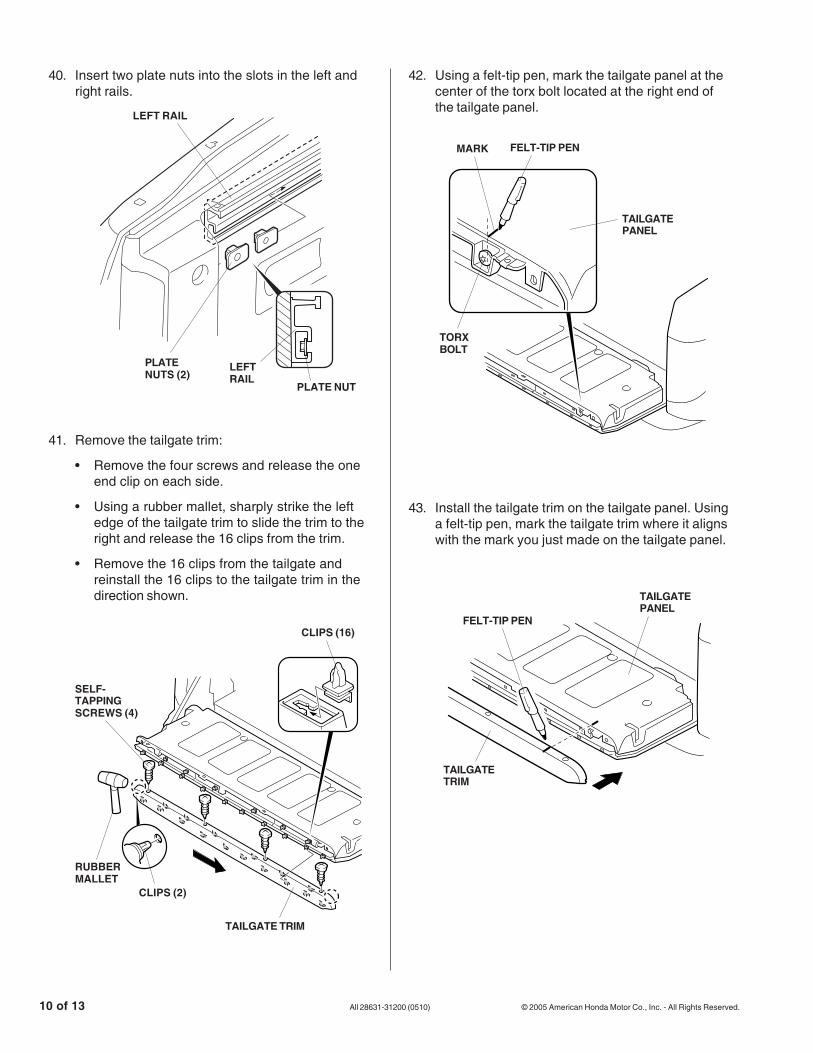
40. Insert two plate nuts into the slots in the left andright rails.
3920241T
PLATE NUT
LEFTRAIL
PLATENUTS (2)
LEFT RAIL
41. Remove the tailgate trim:
• Remove the four screws and release the oneend clip on each side.
• Using a rubber mallet, sharply strike the leftedge of the tailgate trim to slide the trim to theright and release the 16 clips from the trim.
• Remove the 16 clips from the tailgate andreinstall the 16 clips to the tailgate trim in thedirection shown.
42. Using a felt-tip pen, mark the tailgate panel at thecenter of the torx bolt located at the right end ofthe tailgate panel.
3920330T
FELT-TIP PEN
TORXBOLT
MARK
TAILGATEPANEL
43. Install the tailgate trim on the tailgate panel. Usinga felt-tip pen, mark the tailgate trim where it alignswith the mark you just made on the tailgate panel.
3920340T
FELT-TIP PEN
TAILGATEPANEL
TAILGATETRIM
4605081T
SELF-TAPPINGSCREWS (4)
CLIPS (2)
CLIPS (16)
TAILGATE TRIM
RUBBERMALLET

© 2005 American Honda Motor Co., Inc. - All Rights Reserved. All 28631-31200 (0510) 11 of 13
48. Fold the tonneau cover, and attach it to the bedrail. Check that the projection of the bed rail setsin the concave section of the tonneau coversecurely. Note that the tonneau cover is heavy.Work with an assistant when you install thetonneau cover.
44. Remove the tailgate trim. Measure the tailgatetrim from the marked point to the dimensionsshown, and cut out the tailgate trim.
3920350T
23 mm
MARKEDPOINT
TAILGATETRIM
10 mm
29 mm
29 mm
UTILITYKNIFE
45. Remove the torx bolt from the right end of thetailgate panel. Install the lock bracket on thetailgate panel with the TORX bolt you justremoved.
46. Reinstall the tailgate trim.
47. Reinstall the tie down hooks.
3920360T
LOCKBRACKET
TAILGATE PANEL
TORX BOLT(Reuse.)
3920253T
TONNEAUCOVER
TONNEAUCOVER
BED RAIL
push
PROJECTION
CONCAVE
12 of 13 All 28631-31200 (0510) © 2005 American Honda Motor Co., Inc. - All Rights Reserved.
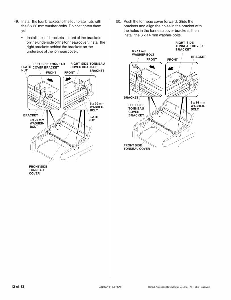
50. Push the tonneau cover forward. Slide thebrackets and align the holes in the bracket withthe holes in the tonneau cover brackets, theninstall the 6 x 14 mm washer-bolts.
49. Install the four brackets to the four plate nuts withthe 6 x 20 mm washer-bolts. Do not tighten themyet.
• Install the left brackets in front of the bracketson the underside of the tonneau cover. Install theright brackets behind the brackets on theunderside of the tonneau cover.
3920272T
FRONT FRONT
LEFT SIDETONNEAUCOVERBRACKET
RIGHT SIDETONNEAU COVERBRACKET6 x 14 mm
WASHER-BOLT
BRACKET
6 x 14 mmWASHER-BOLT
BRACKET
FRONT SIDETONNEAU COVER
3920262T
LEFT SIDE TONNEAUCOVER BRACKET
FRONT FRONT BRACKET
RIGHT SIDE TONNEAUCOVER BRACKET
6 x 20 mmWASHER-BOLT
PLATENUT
6 x 20 mmWASHER-BOLT
PLATENUT
BRACKET
FRONT SIDETONNEAUCOVER

© 2005 American Honda Motor Co., Inc. - All Rights Reserved. All 28631-31200 (0510) 13 of 13
51. Unfold the tonneau cover. Open and close thetailgate 3 to 4 times until the tonneau cover fitsproperly. Then tighten the 6 x 20 mm washer-bolts.
3920321T
6 x 20 mmWASHER-BOLT
6 x 20 mmWASHER-BOLT
FRONT
TAILGATE
TONNEAUCOVERREARPANEL
FRONT
TONNEAU COVERFRONT PANEL
3920293T
KNOBS (2)Turn 90 degrees to lock.
REAR SIDETONNEAU COVER
54. Turn the two knobs to unlock the tonneau cover.
55. Reconnect the negative cable to the battery.
56. Reset the clock, and reset the radio stationpresets.
NOTE: Whenever the battery is disconnected, thedriver’s window AUTO function is disabled.
57. Start the engine. Push down on the driver’swindow switch until the window is fully open.
58. Check that the cargo lights are working.
59. Pull up on the driver’s window switch to close thewindow completely, then hold the switch for2 seconds or more.
60. Lower and raise the window to check the operationof the driver's window AUTO function.
61. Give the keys to your customer.
53. Lock the rear of the tonneau cover by turning thetwo knobs 90 degrees.
52. Attach cushion tape to both hinges. Attach the tape to the front half of the hinge so that it cushions the rear half of the hinge as shown.
3920400T
FRONTSIDETONNEAUCOVERREAR SIDE
TONNEAUCOVER
REAR SIDETONNEAU COVER
FRONT
CUSHIONTAPE
FRONT SIDETONNEAU COVER
HINGE
FRONT
CUSHIONTAPE