Embed Size (px)
Citation preview
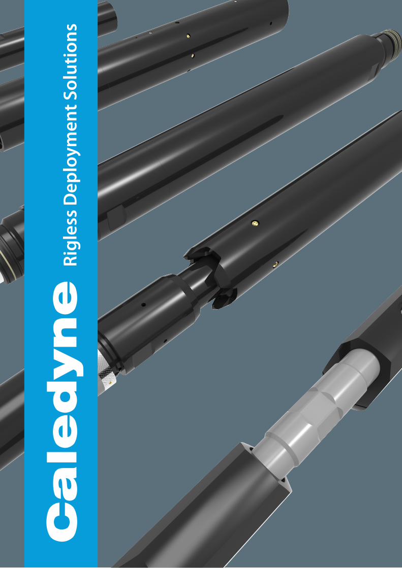
Cale
dyne
Rig
less
Dep
loym
ent S
olut
ions
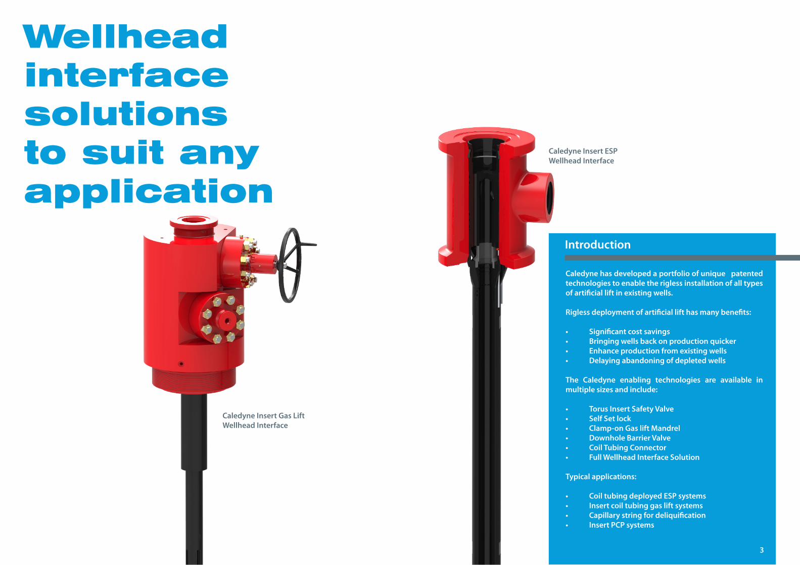
Wellhead interface solutions to suit any application
Caledyne has developed a portfolio of unique patented technologies to enable the rigless installation of all types of artificial lift in existing wells.
Rigless deployment of artificial lift has many benefits:
• Significantcostsavings• Bringingwellsbackonproductionquicker• Enhanceproductionfromexistingwells• Delayingabandoningofdepletedwells
The Caledyne enabling technologies are available in multiple sizes and include:
• TorusInsertSafetyValve• SelfSetlock• Clamp-onGasliftMandrel• DownholeBarrierValve• CoilTubingConnector• FullWellheadInterfaceSolution
Typical applications:
• CoiltubingdeployedESPsystems• Insertcoiltubinggasliftsystems• Capillarystringfordeliquification• InsertPCPsystems
Introduction
CaledyneInsertESPWellheadInterface
CaledyneInsertGasLiftWellheadInterface
3
Contents
5
Torus 06
CT Connector 14
ClamponGasLiftMandrel 18
DSBV 22
Self-SetLockMandrel 26
StuffingBox 30
Stinger 34
HEST 38
CompanyProfile 42
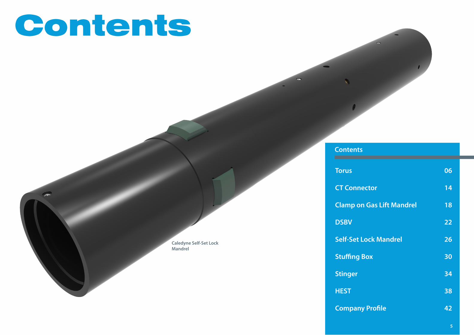
Contents
CaledyneSelf-SetLockMandrel
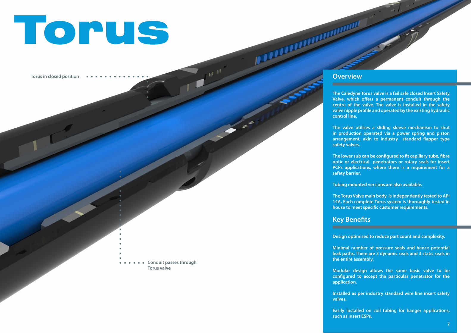
TorusTheCaledyneTorusvalveisafailsafeclosedInsertSafetyValve, which offers a permanent conduit through thecentre of the valve. The valve is installed in the safety valve nipple profile and operated by the existing hydraulic control line.
The valve utilises a sliding sleeve mechanism to shut in production operated via a power spring and piston arrangement, akin to industry standard flapper typesafety valves.
Thelowersubcanbeconfiguredtofitcapillarytube,fibreoptic or electrical penetrators or rotary seals for insert PCPs applications, where there is a requirement for asafety barrier.
Tubing mounted versions are also available.
TheTorusValvemainbodyisindependentlytestedtoAPI14A.EachcompleteTorussystemisthoroughlytestedinhouse to meet specific customer requirements.
Overview
Design optimised to reduce part count and complexity.
Minimal number of pressure seals and hence potentialleakpaths.Thereare3dynamicsealsand3staticsealsinthe entire assembly.
Modular design allows the same basic valve to beconfigured to accept the particular penetrator for the application.
Installedasper industrystandardwire line insertsafetyvalves.
Easily installed on coil tubing for hanger applications, suchasinsertESPs.
KeyBenefits
Conduit passes through Torus valve
Torus in closed position
7
When safety and well
stimulation are key issues
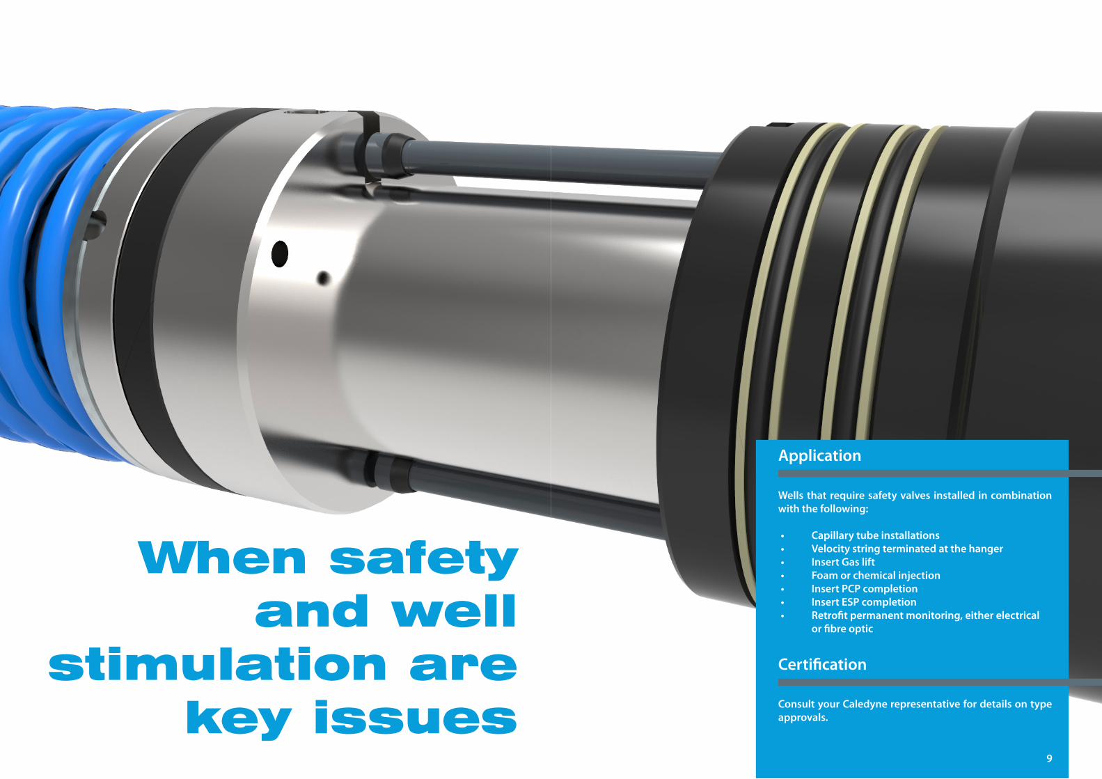
Wellsthatrequiresafetyvalves installed incombinationwith the following:
• Capillarytubeinstallations• Velocitystringterminatedatthehanger• InsertGaslift• Foamorchemicalinjection• InsertPCPcompletion• InsertESPcompletion• Retrofitpermanentmonitoring,eitherelectrical
or fibre optic
Application
Consult your Caledyne representative for details on type approvals.
Certification
9
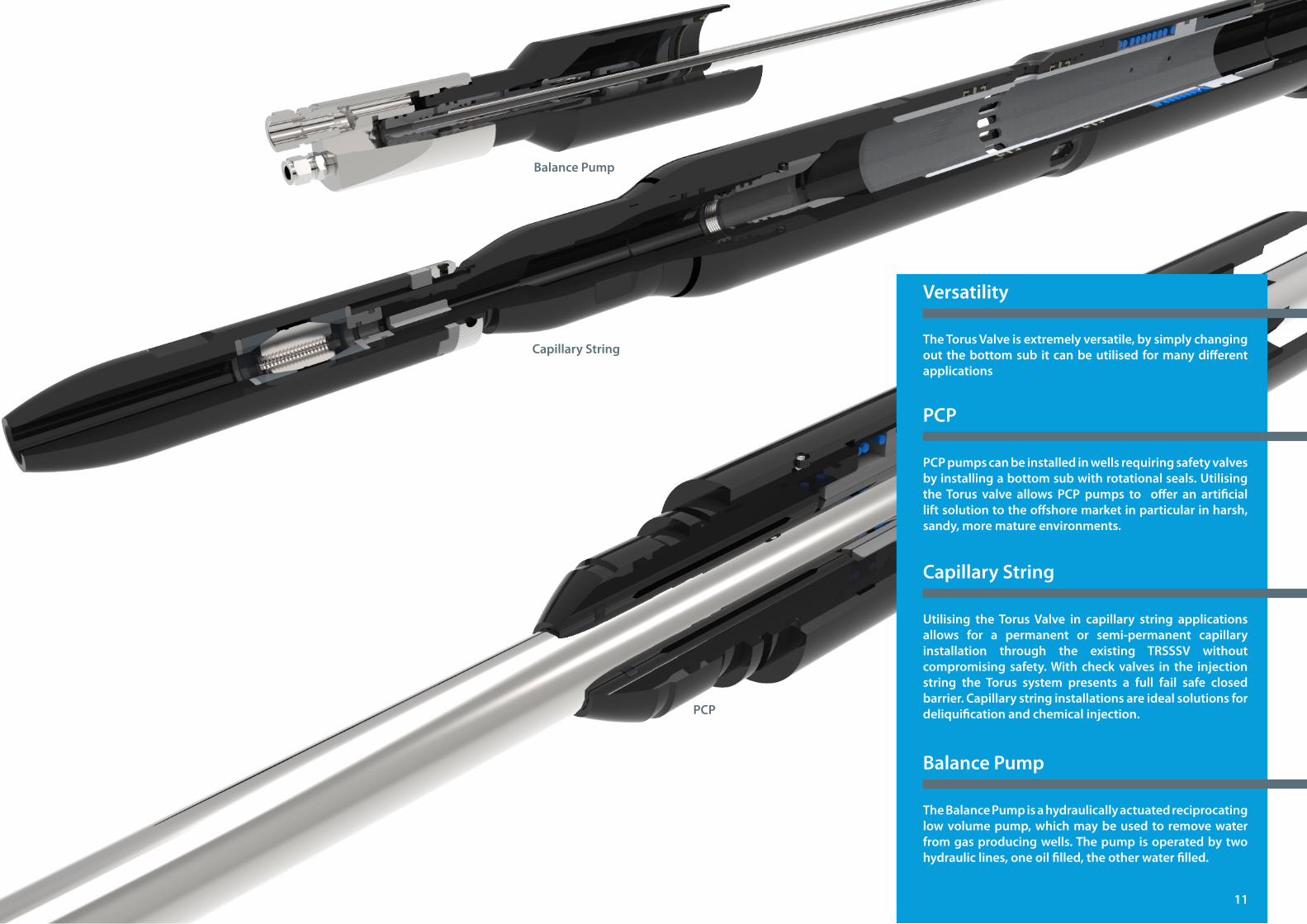
TheTorusValveisextremelyversatile,bysimplychangingout thebottomsub itcanbeutilisedformanydifferentapplications
Versatility
PCPpumpscanbeinstalledinwellsrequiringsafetyvalvesby installing a bottom sub with rotational seals. Utilising theTorus valve allows PCP pumps to offer an artificialliftsolutiontotheoffshoremarketinparticularinharsh,sandy,morematureenvironments.
PCP
Utilising theTorusValve in capillary string applicationsallows for a permanent or semi-permanent capillaryinstallation through the existing TRSSSV withoutcompromising safety.With checkvalves in the injectionstring the Torus system presents a full fail safe closed barrier. Capillary string installations are ideal solutions for deliquificationandchemicalinjection.
Capillary String
TheBalancePumpisahydraulicallyactuatedreciprocatinglowvolumepump,whichmaybeusedtoremovewaterfrom gas producing wells. The pump is operated by two hydrauliclines,oneoilfilled,theotherwaterfilled.
BalancePump
PCP
Capillary String
BalancePump
11
TorusTechnical
Data
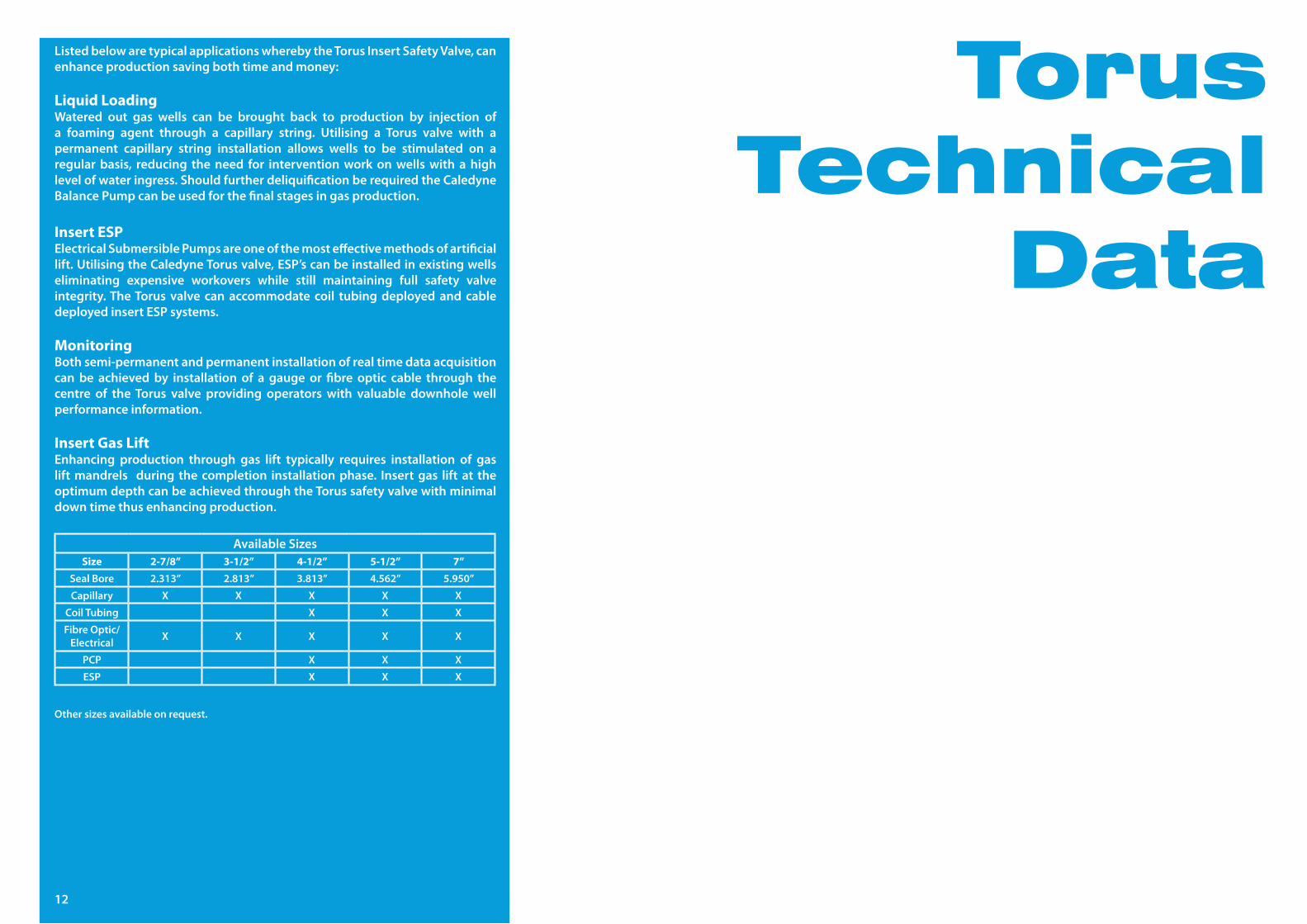
ListedbelowaretypicalapplicationswherebytheTorusInsertSafetyValve,canenhance production saving both time and money:
Liquid LoadingWatered out gas wells can be brought back to production by injection ofa foaming agent through a capillary string. Utilising a Torus valve with a permanent capillary string installation allows wells to be stimulated on a regularbasis, reducing theneed for interventionworkonwellswithahighlevel of water ingress. Should further deliquification be required the Caledyne BalancePumpcanbeusedforthefinalstagesingasproduction.
Insert ESPElectricalSubmersiblePumpsareoneofthemosteffectivemethodsofartificiallift.UtilisingtheCaledyneTorusvalve,ESP’scanbeinstalledinexistingwellseliminating expensive workovers while still maintaining full safety valveintegrity. The Torus valve can accommodate coil tubing deployed and cable deployedinsertESPsystems.
MonitoringBothsemi-permanentandpermanentinstallationofrealtimedataacquisitioncan be achieved by installation of a gauge or fibre optic cable through the centre of the Torus valve providing operators with valuable downhole well performance information.
Insert Gas LiftEnhancing production through gas lift typically requires installation of gasliftmandrels during thecompletion installationphase. Insertgas liftat theoptimum depth can be achieved through the Torus safety valve with minimal down time thus enhancing production.
AvailableSizesSize 2-7/8” 3-1/2” 4-1/2” 5-1/2” 7”
SealBore 2.313” 2.813” 3.813” 4.562” 5.950”
Capillary X X X X X
Coil Tubing X X X
FibreOptic/Electrical X X X X X
PCP X X X
ESP X X X
12
Other sizes available on request.
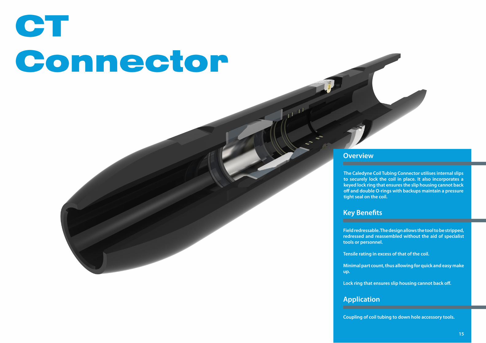
CTConnector
The Caledyne Coil Tubing Connector utilises internal slips to securely lock the coil in place. It also incorporates akeyedlockringthatensuresthesliphousingcannotbackoffanddoubleO-ringswithbackupsmaintainapressuretight seal on the coil.
Overview
Fieldredressable.Thedesignallowsthetooltobestripped,redressed and reassembled without the aid of specialist tools or personnel.
Tensile rating in excess of that of the coil.
Minimalpartcount,thusallowingforquickandeasymakeup.
Lockringthatensuressliphousingcannotbackoff.
Coupling of coil tubing to down hole accessory tools.
KeyBenefits
Application
15
CTConnectorTechnical
Data
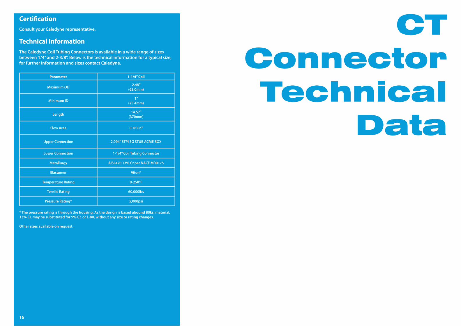
Certification
Technical Information
Parameter 1-1/4” Coil
MaximumOD 2.48”(63.0mm)
MinimumID 1”(25.4mm)
Length 14.57”(370mm)
FlowArea 0.785in2
Upper Connection 2.094”8TPI3GSTUBACMEBOX
LowerConnection 1-1/4”CoilTubingConnector
Metallurgy AISI42013%CrperNACEMR0175
Elastomer Viton®
Temperature Rating 0-250°F
Tensile Rating 60,000lbs
PressureRating* 5,000psi
Consult your Caledyne representative.
*Thepressureratingisthroughthehousing.Asthedesignisbasedabound80ksimaterial,13%Cr.maybesubstitutedfor9%Cr.orL-80,withoutanysizeorratingchanges.
Other sizes available on request.
The Caledyne Coil Tubing Connectors is available in a wide range of sizes between1/4”and2-3/8”.Belowisthetechnicalinformationforatypicalsize,for further information and sizes contact Caledyne.
16
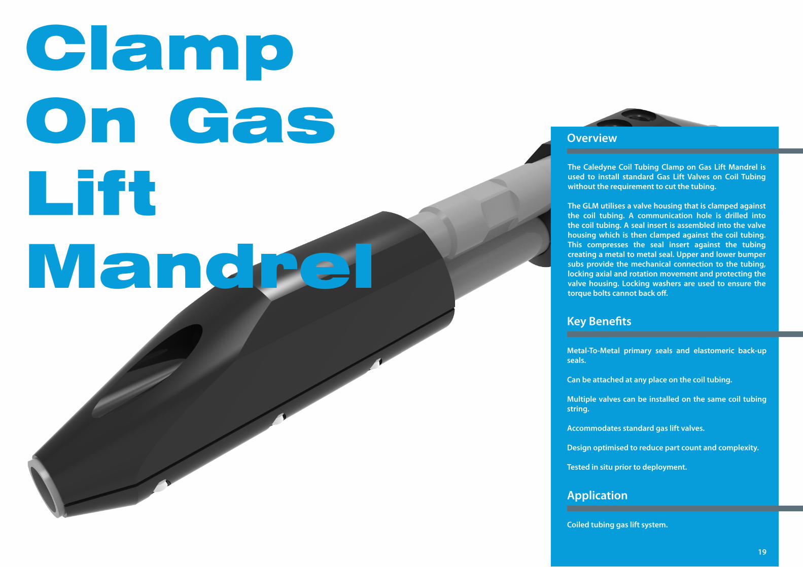
Clamp On Gas Lift Mandrel
TheCaledyneCoilTubingClamponGasLiftMandrel isused to install standard Gas Lift Valves on Coil Tubingwithout the requirement to cut the tubing.
TheGLMutilisesavalvehousingthatisclampedagainstthe coil tubing. A communication hole is drilled intothecoiltubing.Asealinsertisassembledintothevalvehousing which is then clamped against the coil tubing. This compresses the seal insert against the tubing creating a metal to metal seal. Upper and lower bumper subsprovide themechanical connection to the tubing,lockingaxialandrotationmovementandprotectingthevalve housing. Lockingwashers are used to ensure thetorqueboltscannotbackoff.
Overview
Metal-To-Metal primary seals and elastomeric back-upseals.
Can be attached at any place on the coil tubing.
Multiplevalvescanbe installedonthesamecoil tubingstring.
Accommodatesstandardgasliftvalves.
Design optimised to reduce part count and complexity.
Tested in situ prior to deployment.
Coiled tubing gas lift system.
KeyBenefits
Application
19
Clamp on Gas Lift Mandrel
Technical Data
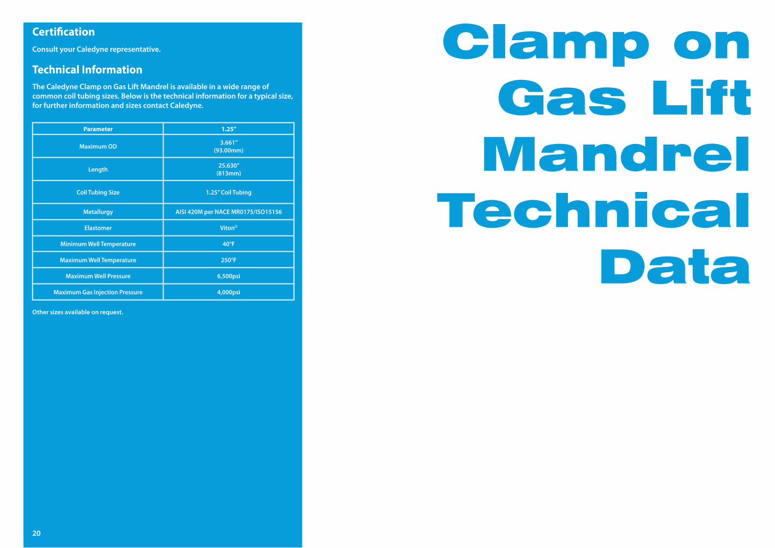
Certification
Technical Information
Parameter 1.25”
MaximumOD 3.661”(93.00mm)
Length 25.630”(813mm)
Coil Tubing Size 1.25”CoilTubing
Metallurgy AISI420MperNACEMR0175/ISO15156
Elastomer Viton®
MinimumWellTemperature 40°F
MaximumWellTemperature 250°F
MaximumWellPressure 6,500psi
MaximumGasInjectionPressure 4,000psi
Consult your Caledyne representative.
Other sizes available on request.
20
TheCaledyneClamponGasLiftMandrelisavailableinawiderangeofcommoncoiltubingsizes.Belowisthetechnicalinformationforatypicalsize,for further information and sizes contact Caledyne.
Deep
Set
Barrier
Valve
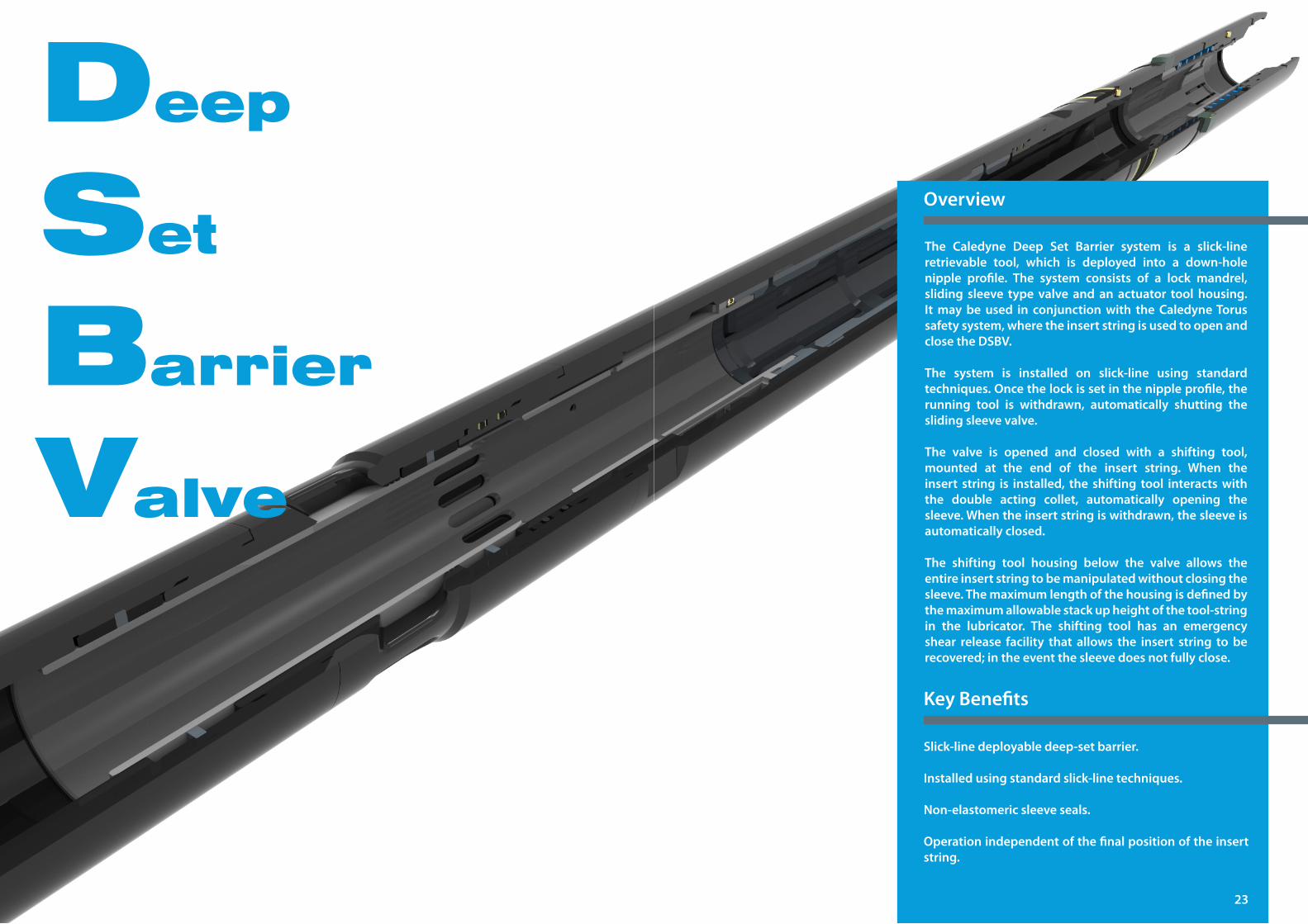
The Caledyne Deep Set Barrier system is a slick-lineretrievable tool, which is deployed into a down-holenipple profile. The system consists of a lock mandrel,sliding sleeve type valve and an actuator tool housing. Itmaybeused in conjunctionwith theCaledyneTorussafetysystem,wheretheinsertstringisusedtoopenandclosetheDSBV.
The system is installed on slick-line using standardtechniques.Oncethelockissetinthenippleprofile,therunning tool is withdrawn, automatically shutting thesliding sleeve valve.
The valve is opened and closed with a shifting tool,mounted at the end of the insert string. When theinsert string is installed, the shifting tool interactswiththe double acting collet, automatically opening thesleeve.Whentheinsertstringiswithdrawn,thesleeveisautomatically closed.
The shifting tool housing below the valve allows the entire insert string to be manipulated without closing the sleeve. The maximum length of the housing is defined by themaximumallowablestackupheightofthetool-stringin the lubricator. The shifting tool has an emergency shear release facility that allows the insert string to be recovered; in the event the sleeve does not fully close.
Overview
Slick-linedeployabledeep-setbarrier.
Installedusingstandardslick-linetechniques.
Non-elastomericsleeveseals.
Operation independent of the final position of the insert string.
KeyBenefits
23
DSBVTechnical
Data
Application
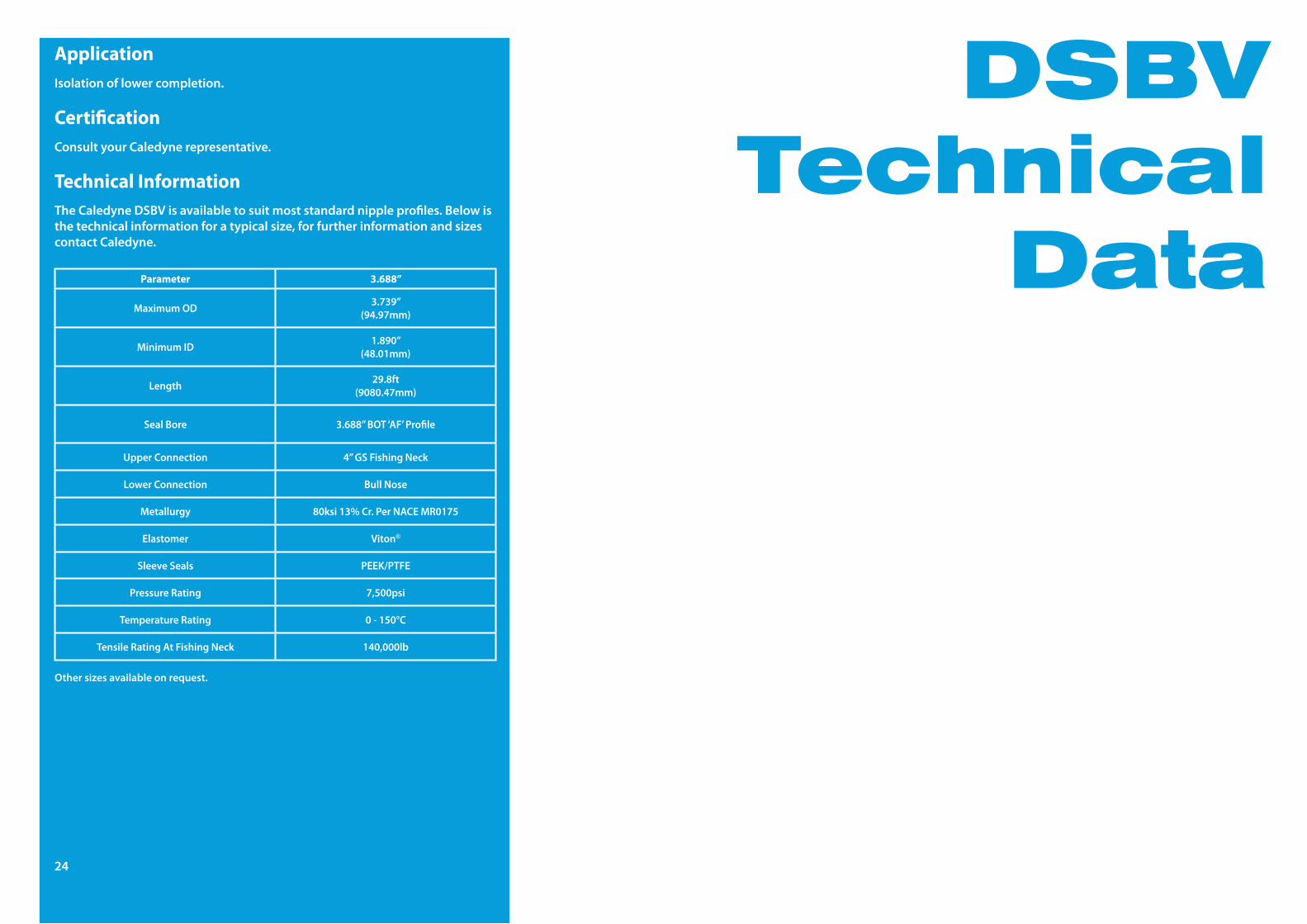
Certification
Technical Information
Parameter 3.688”
MaximumOD 3.739”(94.97mm)
MinimumID 1.890”(48.01mm)
Length 29.8ft(9080.47mm)
SealBore 3.688”BOT‘AF’Profile
Upper Connection 4”GSFishingNeck
LowerConnection BullNose
Metallurgy 80ksi13%Cr.PerNACEMR0175
Elastomer Viton®
Sleeve Seals PEEK/PTFE
PressureRating 7,500psi
Temperature Rating 0-150°C
TensileRatingAtFishingNeck 140,000lb
Isolationoflowercompletion.
Consult your Caledyne representative.
Other sizes available on request.
24
TheCaledyneDSBVisavailabletosuitmoststandardnippleprofiles.Belowisthetechnicalinformationforatypicalsize,forfurtherinformationandsizescontact Caledyne.
Self-Set Lock Mandrel
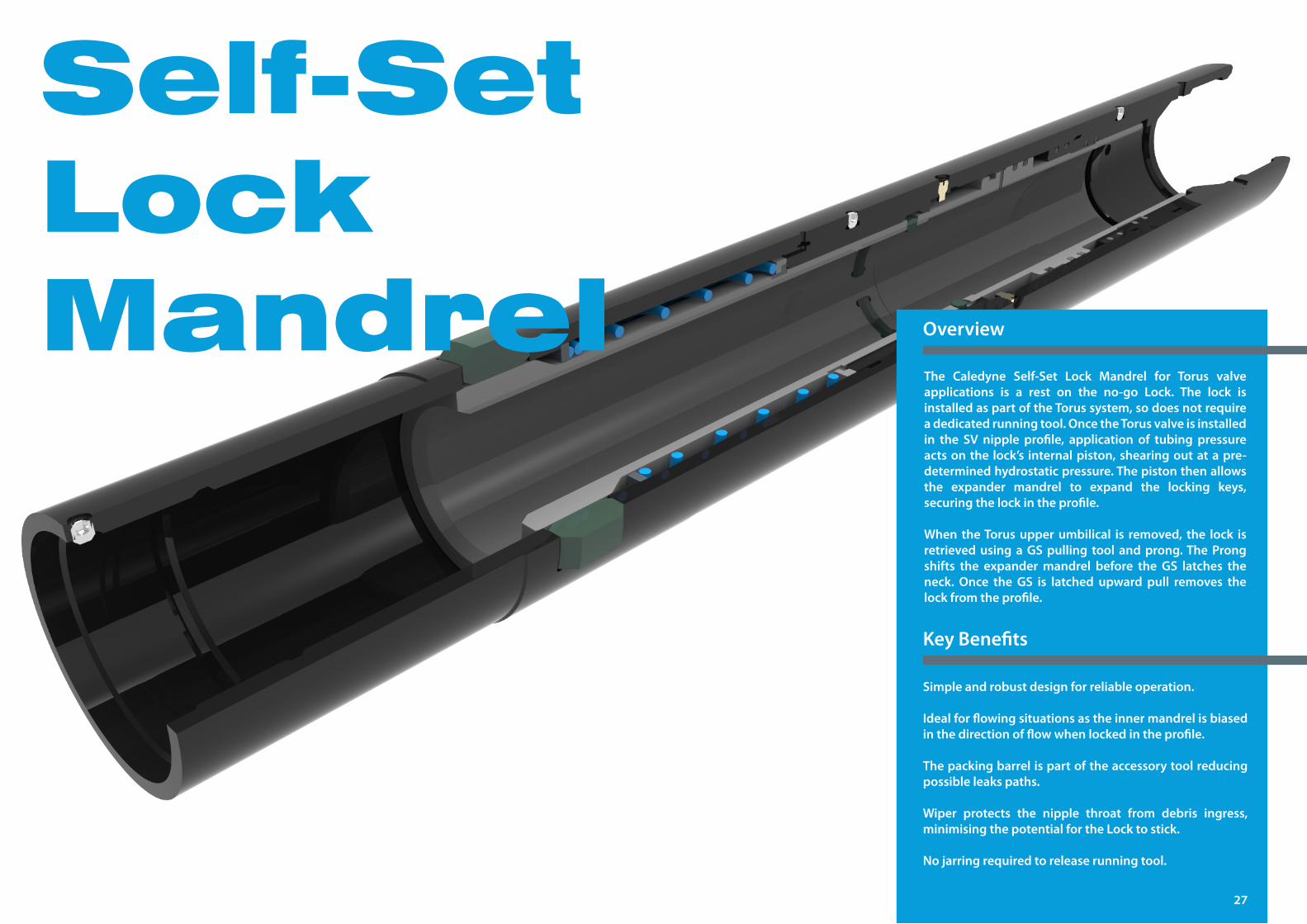
The Caledyne Self-Set Lock Mandrel for Torus valveapplications is a rest on the no-go Lock. The lock isinstalledaspartoftheTorussystem,sodoesnotrequirea dedicated running tool. Once the Torus valve is installed in the SV nipple profile, application of tubing pressureactsonthe lock’s internalpiston,shearingoutatapre-determined hydrostatic pressure. The piston then allows the expander mandrel to expand the locking keys,securingthelockintheprofile.
When theTorusupperumbilical is removed, the lock isretrievedusingaGSpulling tool andprong.TheProngshifts the expandermandrel before the GS latches theneck. Once the GS is latched upward pull removes thelockfromtheprofile.
Overview
Simple and robust design for reliable operation.
Idealforflowingsituationsastheinnermandrelisbiasedinthedirectionofflowwhenlockedintheprofile.
Thepackingbarrelispartoftheaccessorytoolreducingpossibleleakspaths.
Wiper protects the nipple throat from debris ingress,minimisingthepotentialfortheLocktostick.
Nojarringrequiredtoreleaserunningtool.
KeyBenefits
27
Self-Set Lock
MandrelTechnical
Data
Certification
Application
Technical Information
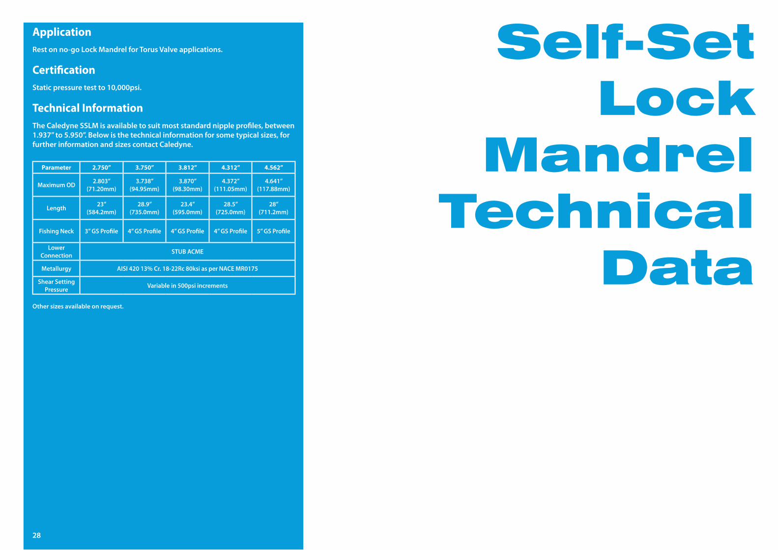
Parameter 2.750” 3.750” 3.812” 4.312” 4.562”
MaximumOD 2.803”(71.20mm)
3.738”(94.95mm)
3.870”(98.30mm)
4.372”(111.05mm)
4.641”(117.88mm)
Length 23”(584.2mm)
28.9”(735.0mm)
23.4”(595.0mm)
28.5”(725.0mm)
28”(711.2mm)
FishingNeck 3”GSProfile 4”GSProfile 4”GSProfile 4”GSProfile 5”GSProfile
LowerConnection STUBACME
Metallurgy AISI42013%Cr.18-22Rc80ksiasperNACEMR0175
Shear Setting Pressure Variablein500psiincrements
Staticpressuretestto10,000psi.
Restonno-goLockMandrelforTorusValveapplications.
Other sizes available on request.
28
TheCaledyneSSLMisavailabletosuitmoststandardnippleprofiles,between1.937”to5.950”.Belowisthetechnicalinformationforsometypicalsizes,forfurther information and sizes contact Caledyne.
Stuffing Box
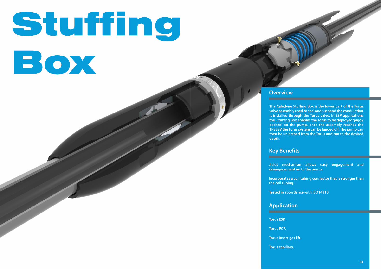
TheCaledyneStuffingBoxisthelowerpartoftheTorusvalve assembly used to seal and suspend the conduit that is installed through theTorusvalve. InESPapplicationstheStuffingBoxenablestheTorustobedeployed‘piggybacked’ on the pump, once the assembly reaches theTRSSSVtheTorussystemcanbelandedoff.Thepumpcanthen be unlatched from the Torus and run to the desired depth.
Overview
J-slot mechanism allows easy engagement anddisengagement on to the pump.
Incorporatesacoiltubingconnectorthatisstrongerthanthe coil tubing.
TestedinaccordancewithISO14310
TorusESP.
TorusPCP.
Torus insert gas lift.
Torus capillary.
KeyBenefits
Application
31
Stuffing Box
Technical Data
Certification
Technical Information
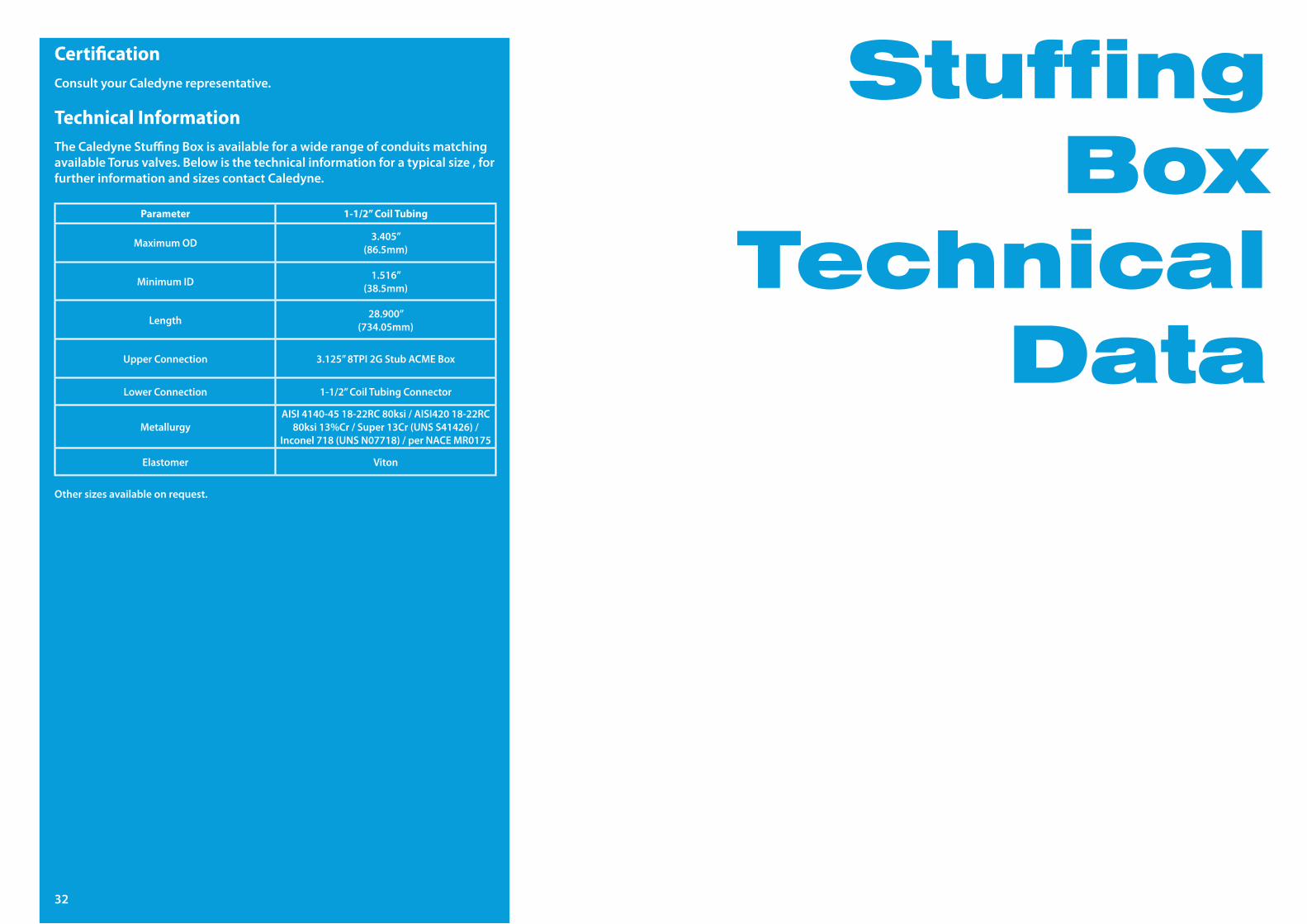
Parameter 1-1/2” Coil Tubing
MaximumOD 3.405”(86.5mm)
MinimumID 1.516”(38.5mm)
Length 28.900”(734.05mm)
Upper Connection 3.125”8TPI2GStubACMEBox
LowerConnection 1-1/2”CoilTubingConnector
MetallurgyAISI4140-4518-22RC80ksi/AISI42018-22RC
80ksi13%Cr/Super13Cr(UNSS41426)/Inconel718(UNSN07718)/perNACEMR0175
Elastomer Viton
Consult your Caledyne representative.
Other sizes available on request.
32
TheCaledyneStuffingBoxisavailableforawiderangeofconduitsmatchingavailableTorusvalves.Belowisthetechnicalinformationforatypicalsize,forfurther information and sizes contact Caledyne.
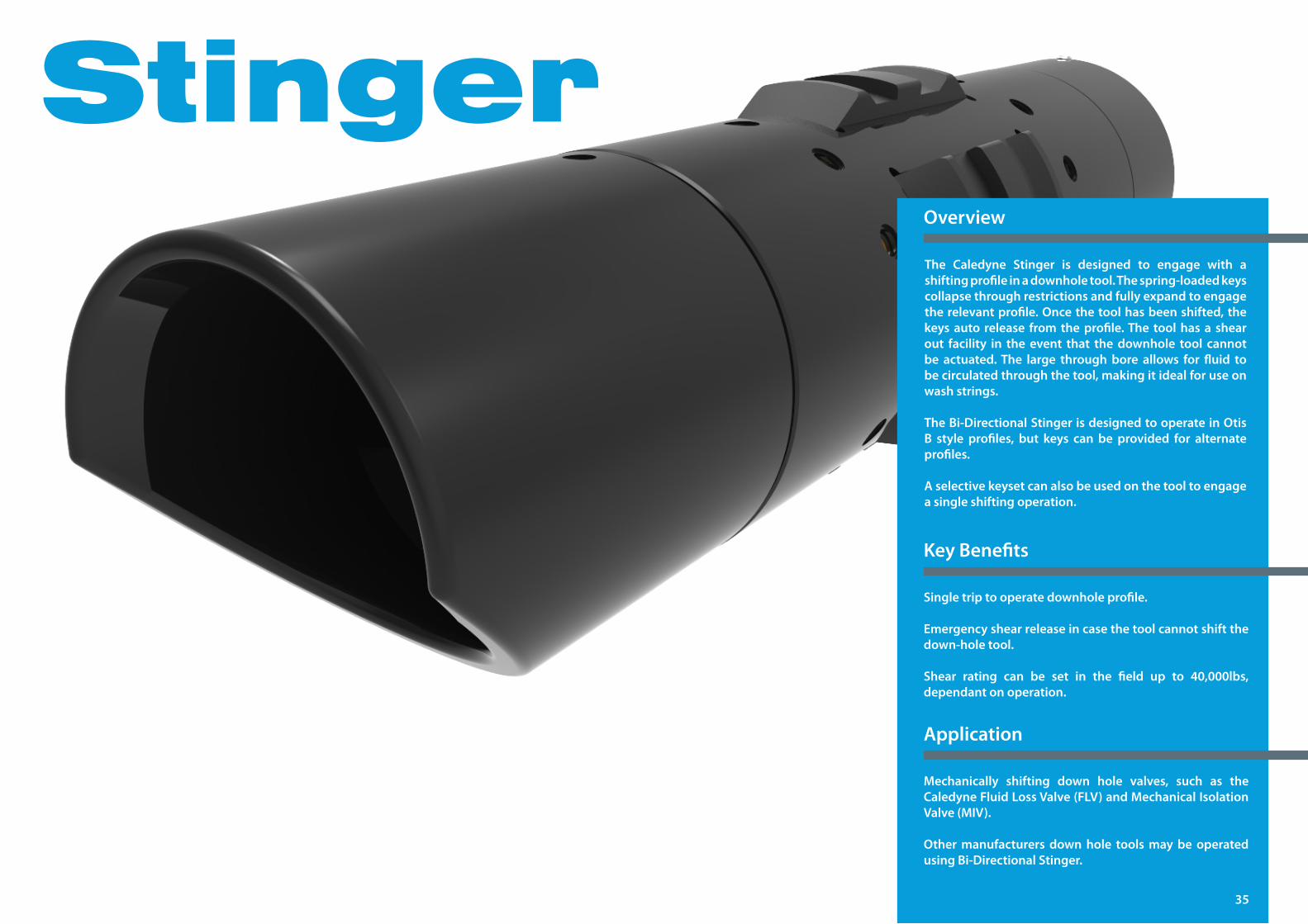
StingerThe Caledyne Stinger is designed to engage with a shiftingprofileinadownholetool.Thespring-loadedkeyscollapse through restrictions and fully expand to engage therelevantprofile.Oncethetoolhasbeenshifted,thekeysauto release fromtheprofile.The toolhasa shearout facility in the event that the downhole tool cannot be actuated.The large throughbore allows for fluid tobecirculatedthroughthetool,makingitidealforuseonwash strings.
TheBi-DirectionalStingerisdesignedtooperateinOtisB style profiles, but keys can be provided for alternateprofiles.
Aselectivekeysetcanalsobeusedonthetooltoengagea single shifting operation.
Overview
Single trip to operate downhole profile.
Emergencyshearreleaseincasethetoolcannotshiftthedown-holetool.
Shear rating can be set in the field up to 40,000lbs,dependant on operation.
Mechanically shifting down hole valves, such as theCaledyneFluidLossValve(FLV)andMechanicalIsolationValve(MIV).
Other manufacturers down hole tools may be operated usingBi-DirectionalStinger.
KeyBenefits
Application
35
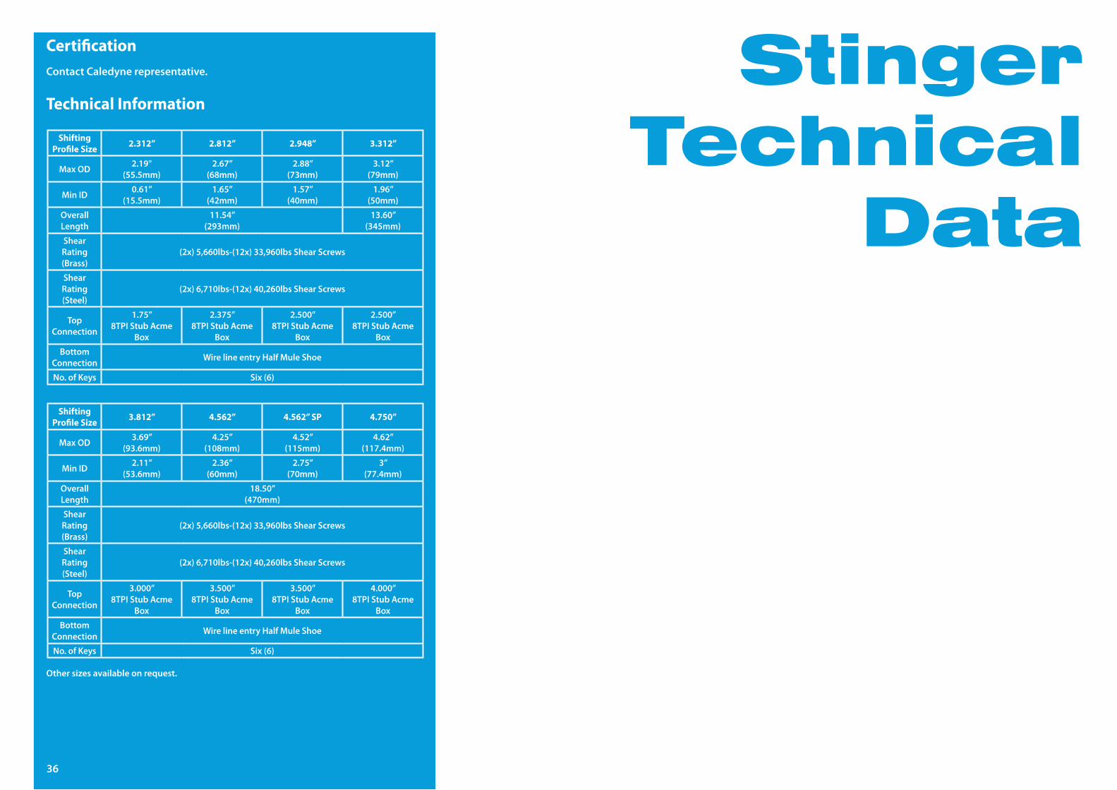
Technical Information
CertificationContact Caledyne representative.
Shifting Profile Size 2.312” 2.812” 2.948” 3.312”
MaxOD 2.19"(55.5mm)
2.67”(68mm)
2.88”(73mm)
3.12”(79mm)
MinID 0.61”(15.5mm)
1.65”(42mm)
1.57”(40mm)
1.96”(50mm)
Overall Length
11.54”(293mm)
13.60”(345mm)
Shear Rating(Brass)
(2x)5,660lbs-(12x)33,960lbsShearScrews
Shear Rating(Steel)
(2x)6,710lbs-(12x)40,260lbsShearScrews
Top Connection
1.75”8TPIStubAcme
Box
2.375”8TPIStubAcme
Box
2.500”8TPIStubAcme
Box
2.500”8TPIStubAcme
Box
BottomConnection WirelineentryHalfMuleShoe
No.ofKeys Six (6)
Shifting Profile Size 3.812” 4.562” 4.562” SP 4.750”
MaxOD 3.69”(93.6mm)
4.25”(108mm)
4.52”(115mm)
4.62”(117.4mm)
MinID 2.11”(53.6mm)
2.36”(60mm)
2.75”(70mm)
3”(77.4mm)
Overall Length
18.50”(470mm)
Shear Rating(Brass)
(2x)5,660lbs-(12x)33,960lbsShearScrews
Shear Rating(Steel)
(2x)6,710lbs-(12x)40,260lbsShearScrews
Top Connection
3.000”8TPIStubAcme
Box
3.500”8TPIStubAcme
Box
3.500”8TPIStubAcme
Box
4.000”8TPIStubAcme
Box
BottomConnection WirelineentryHalfMuleShoe
No.ofKeys Six (6)
Other sizes available on request.
StingerTechnical
Data
36
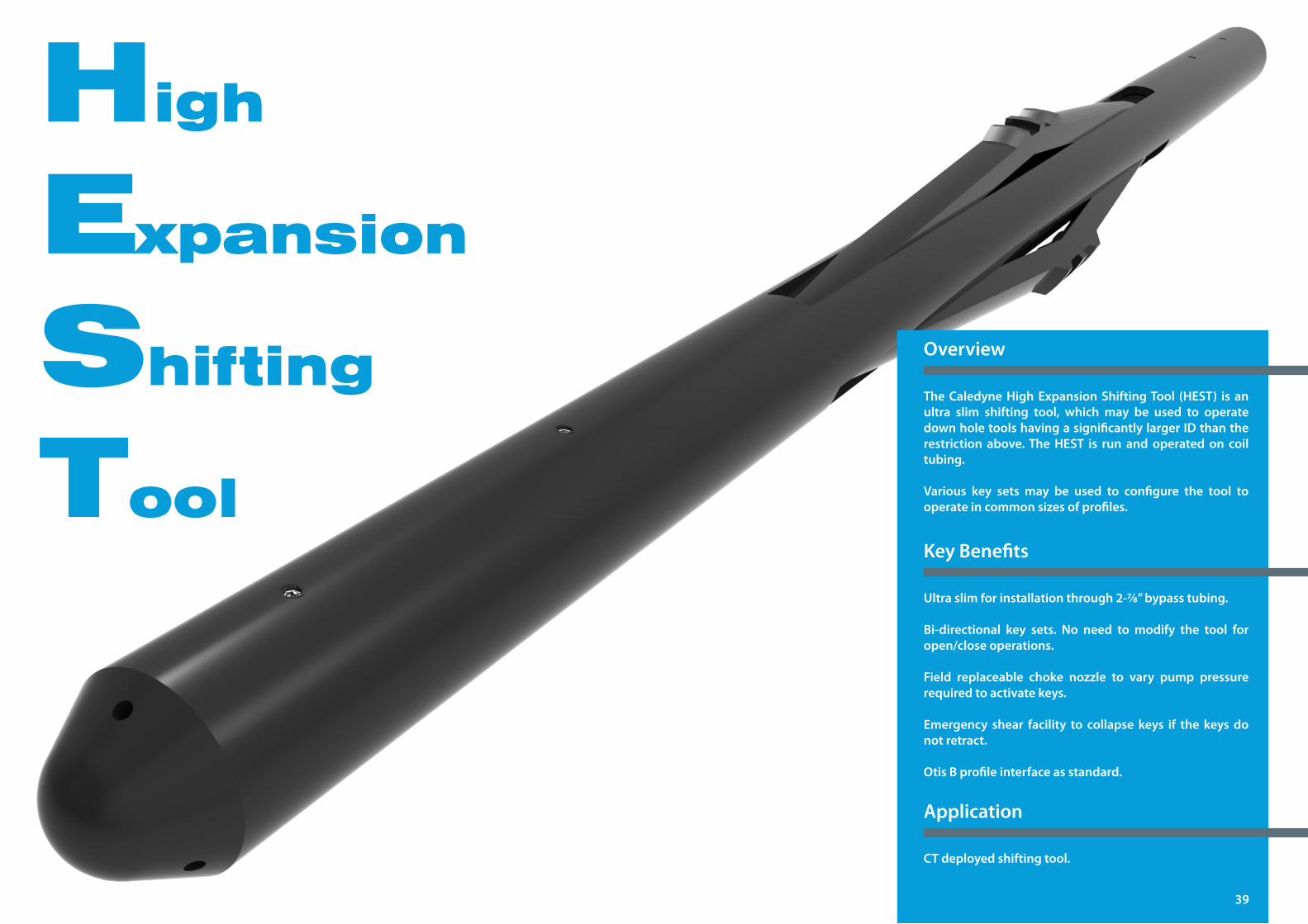
High
Expansion
Shifting
Tool
TheCaledyneHighExpansionShiftingTool (HEST) is anultra slim shifting tool, which may be used to operatedownholetoolshavingasignificantlylargerIDthantherestriction above.TheHEST is run andoperatedon coiltubing.
Various key sets may be used to configure the tool tooperate in common sizes of profiles.
Overview
Ultraslimforinstallationthrough2-7/8”bypasstubing.
Bi-directional key sets. No need to modify the tool foropen/closeoperations.
Field replaceable choke nozzle to vary pump pressurerequiredtoactivatekeys.
Emergency shear facility to collapse keys if the keysdonot retract.
OtisBprofileinterfaceasstandard.
CT deployed shifting tool.
KeyBenefits
Application
39
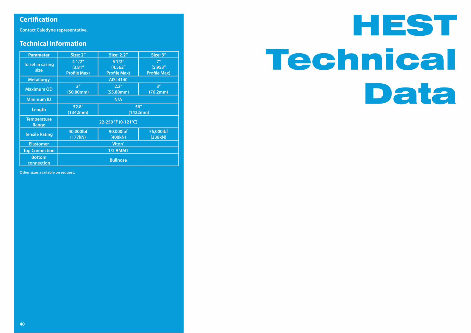
HESTTechnical
Data
40
Parameter Size: 2” Size: 2.2” Size: 3”
To set in casing size
41/2”(3.81”
ProfileMax)
51/2”(4.562”
ProfileMax)
7”(5.953”
ProfileMax)Metallurgy AISI4140
MaximumOD 2”(50.80mm)
2.2”(55.88mm)
3”(76.2mm)
MinimumID N/A
Length 52.8”(1342mm)
56”(1422mm)
Temperature Range 22-250°F(0-121°C)
Tensile Rating 40,000lbf(177kN)
90,000lbf(400kN)
76,000lbf(338kN)
Elastomer Viton®
Top Connection 1/2AMMTBottom
connection Bullnose
Other sizes available on request.
Technical Information
CertificationContact Caledyne representative.
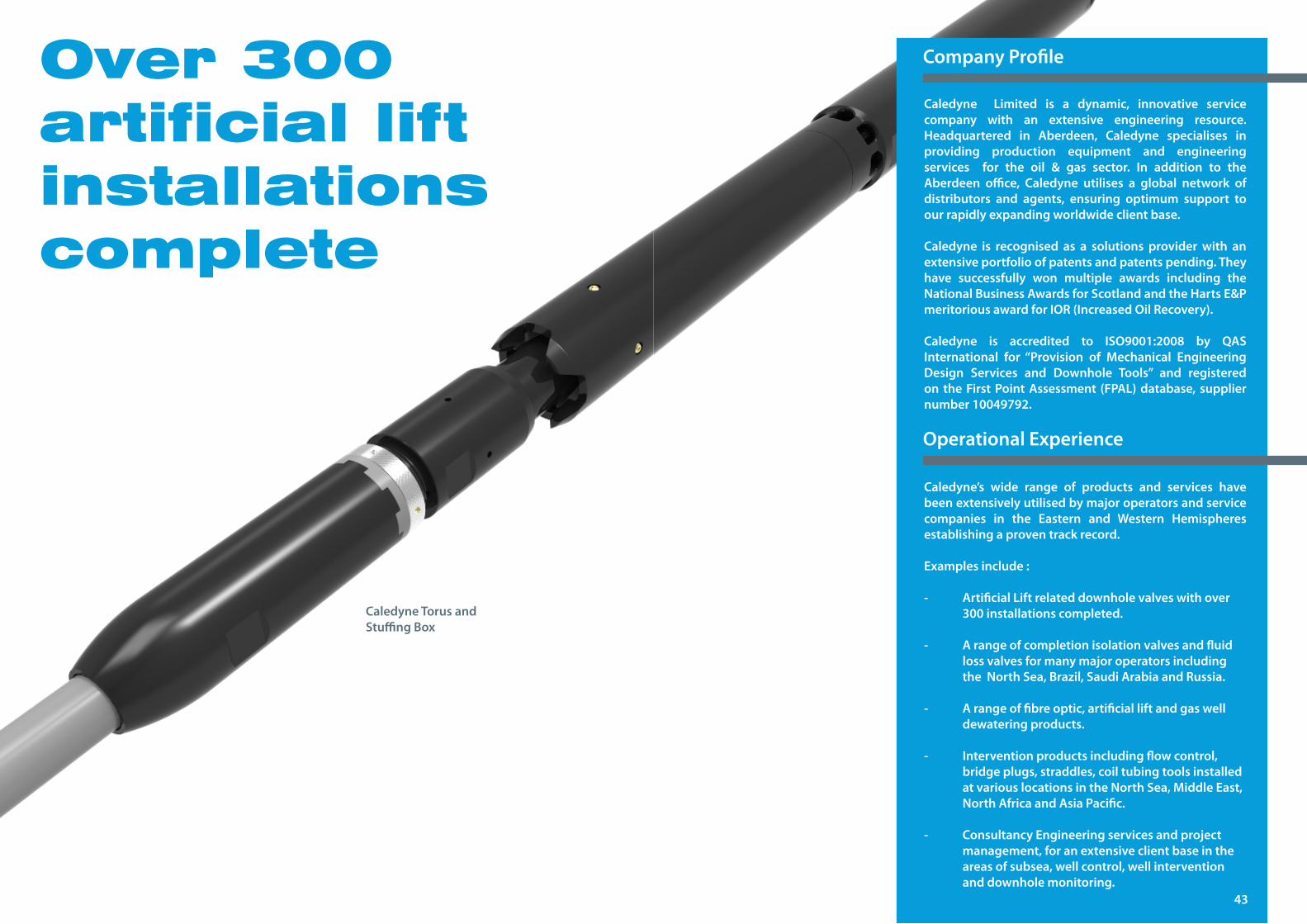
Over 300 artificial lift installations complete
Caledyne Limited is a dynamic, innovative servicecompany with an extensive engineering resource. Headquartered in Aberdeen, Caledyne specialises inproviding production equipment and engineering services for the oil & gas sector. In addition to theAberdeen office, Caledyne utilises a global network ofdistributors and agents, ensuring optimum support toour rapidly expanding worldwide client base.
Caledyne is recognised as a solutions provider with an extensive portfolio of patents and patents pending. They have successfully won multiple awards including the NationalBusinessAwardsforScotlandandtheHartsE&PmeritoriousawardforIOR(IncreasedOilRecovery).
Caledyne is accredited to ISO9001:2008 by QASInternational for “Provision of Mechanical EngineeringDesign Services and Downhole Tools” and registeredontheFirstPointAssessment (FPAL)database, suppliernumber10049792.
Caledyne’s wide range of products and services havebeenextensivelyutilisedbymajoroperatorsandservicecompanies in the Eastern and Western Hemispheresestablishingaproventrackrecord.
Examplesinclude:
- ArtificialLiftrelateddownholevalveswithover 300 installations completed. - Arangeofcompletionisolationvalvesandfluid lossvalvesformanymajoroperatorsincluding theNorthSea,Brazil,SaudiArabiaandRussia. - Arangeoffibreoptic,artificialliftandgaswell dewatering products. - Interventionproductsincludingflowcontrol, bridgeplugs,straddles,coiltubingtoolsinstalled atvariouslocationsintheNorthSea,MiddleEast, NorthAfricaandAsiaPacific.
- ConsultancyEngineeringservicesandproject management,foranextensiveclientbaseinthe areasofsubsea,wellcontrol,wellintervention and downhole monitoring.
CompanyProfile
OperationalExperience
43
Caledyne Torus and StuffingBox

CaledyneLtdUnit24,TwinSpiresMugiemossRoad
AberdeenAB219BG
Tel: +44(0)1224826827Email:[email protected]: www.caledyne.co.uk
Copyright©2015CaledyneLtd