Embed Size (px)
Citation preview
RIS p A IL
,
COD. 14 92 01 !is _ .... '77.77 ......... 7, M7_ .... VtOlO ••• tOlOIP-Ccid. U.'Ut
The 1!I" s l.allons end due.lpllono In !hI. ",on .. el • •• Ind lcall •• only, Ih a ",a n .. racl ... e •• a.arvlng lI.e ll !he . lg"1 10 Introduce wltllo .. 1 noUce . ny ",odltlca Uon It .... y de.", n.e .... " 10' a b.n., ptlr10rmanea 01 Iha ",olo.cycle or lo r conltruetlve or eo",,,, .. cla l reason •.
SEIMM MOTO GUZZI + SERVIZIO PUBBLICAZIONI TECNICHE
COD 14920156
lO00K· 1179 - Prinled In lla l ~. Maflan,· AIInIII Bergamo
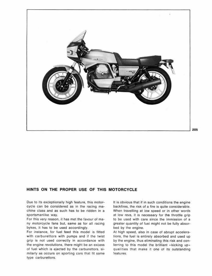
HINTS ON THE PROPER USE OF THIS MOTORCYCLE
Due to its exc'eptionally high feature, this motorcycle can be considered as in the racing machine c lass and as such has to be ridden in a sportsmanlike way. For this very reason , it has met the favour of many motorcycle fa ns but, same as for all racing bykes. it has to be used accordingly. For instance, for fuel feed this model is filted with carburettors with pumps and if the twist grip is not used correctly in accordance wi th the engine revolutions , there might be an excess of fuel which is ejected by the carburettors, similarly as occurs on sporting cars thai fil same type ca rburettors.
It is obvious thai if in such conditions the engine backfires, the risk of a fire is quite considerable. When travelling at low speed or in other words at low revs, it is necessary for the throttle grip to be used with care since the immission of a greater quantity of fuel might not be fully absorbed by the engine. At high speed. also in case of abrupt accelerations. the fuel is entirely absorbed and used up by the engine, thus eliminating this risk and conferring to this model the brilliant " kicking up .. qual ities that make it one of its outstanding features.
205

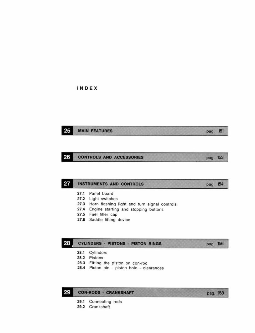
IN 0 EX
tti MAIN FEATURES
CONTROLS AND ACCESSORIES
INSTRUMENTS AND CONTROLS
27.1 Panel board 27.2 Ligh t switches 27.3 Horn flashing light and turn Signal contro ls 27.4 Engine starl ing and stopping buttons 27.5 Fuel filler cap 27.6 Saddle lifting device
CYUNDERS - PISTONS - PISTON RINGS
28.1 Cylinders 28.2 Pistons 28.3 Fitting the piston on con-rod 28.4 Piston pin • piston hole - c learances
CON-RODS - CRANKSHAFT
29.1 Connecting rods 29.2 Crankshaft
pag. 151
pag. 153
pag. 154
pag. 156
pog. 156
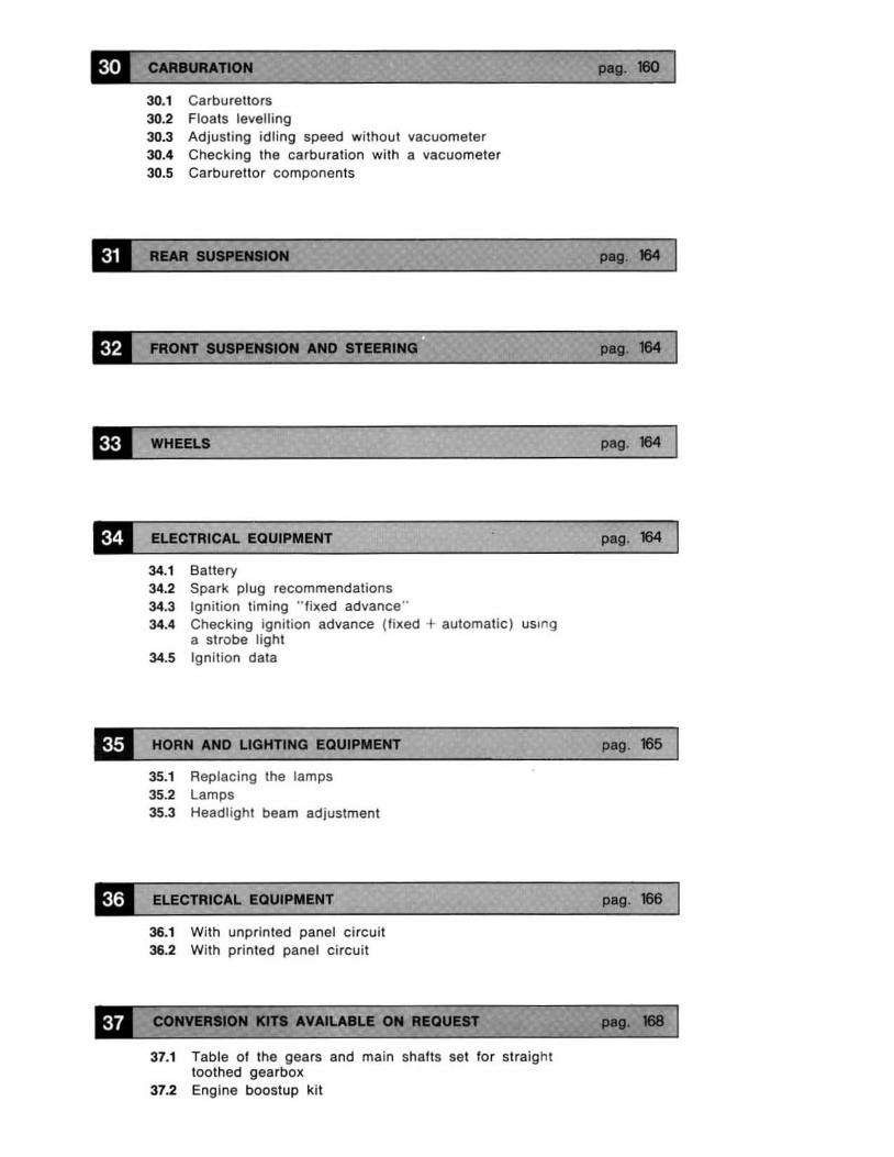
30.1 Carburettors 30.2 Floats levelling 30.3 Adjusting idling speed without vaeuorneter 30.4 Checking the carburation with a vaeuorneter 30.5 Carburettor components
FRONT 8118_ ANa
WHEELS
ELECTRICAL EQUIPMENT
34.1 Battery 34.2 Spark plug recommendations 34.3 Ignit ion tim ing " lJxed advance " 34.4 Checking Ign il ion advance (fixed + automatic ) uSing
a strobe light 34.5 Ign ition data
HORN AND LIGHTING EQUIPMENT
35.1 Repl acing the lamps 35.2 Lamps 35.3 Headl ight beam adjustment
ELECTRICAL EQUIPMENT
36.1 With unprinted panel circuit 36.2 With printed panel circuit
37.1 Table 01 the gears and main shafts sel for straight toothed gearbox
37.2 Engine booslup kit
peg. 1110
peg. 184
pag. 184
psg. 184
psg. 165
psg. 166
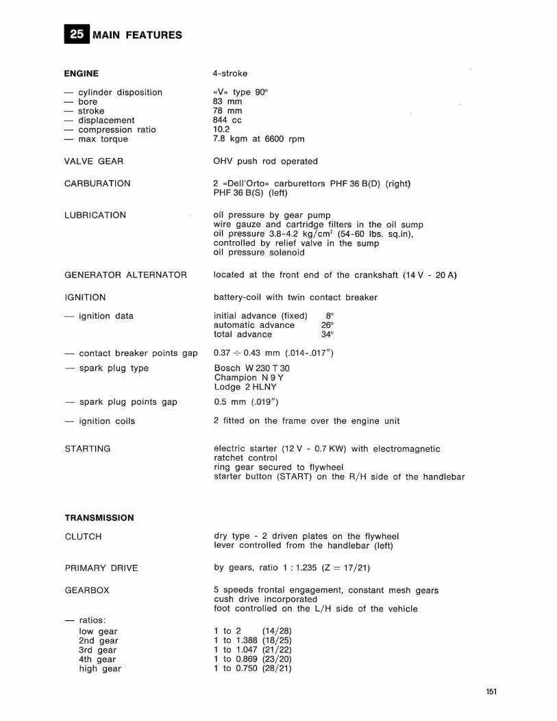
ElMAIN FEATURES
ENGINE
- cylinder disposition - bore - stroke - displacement - compression ratio - max torque
VALVE GEAR
CARBURATION
LUBRICATION
GENERATOR ALTERNATOR
IGNITION
- ignition data
- contact breaker points gap
- spark plug type
- spark plug pOints gap
- ignition coils
STARTING
TRANSMISSION
CLUTCH
PRIMARY DRIVE
GEARBOX
- ratios: low gear 2nd gear 3rd gear 4th gear high gear
4-stroke
«V .. type 90" 83 mm 78 mm 844 cc 10.2 7.8 kgm at 6600 rpm
OHV push rod operated
2 «DelJ 'Orto» carbu rettors PHF 36 8(0) (right) PHF 36 8(S) (left)
oil pressure by gear pump wire gauze and cart ridg e fi lters in the oil sump oi l pressure 3.8-4.2 kg/ cm2 (54-60 Ibs. sq.in) , controll ed by rel ief valve in the sump oi l pressure solenoid
located at the front end of the crankshaft (14 V - 20 A)
battery-coi l with twin contact breaker
initial advance (fixed) 8" automatic advance 26" total advance 34"
0.37 -:- 0.43 mm (.014-.017" )
Bosch W 230 T 30 Champion N 9 Y Lodge 2 HLNY
0.5 mm (.019")
2 fitted on the frame over the engine unit
electric starter (12 V - 0.7 KW) with electromagnetic ratchet control ring gear secured to flywheel starter button (START) on the R/ H side of the handlebar
dry type - 2 driven plates on the flywheel lever controlled from the handlebar (left)
by gears, ratio 1 : 1.235 (Z = 17/ 21)
5 speeds frontal engagement, constant mesh gears cush drive incorporated foot controlled on the L/ H side of the vehicle
1 to 2 1 to 1.388 1 to 1.047 1 to 0.869 1 to 0.750
(14/ 28) (18/ 25) (21/ 22) (23/ 20) (28/ 21)
151
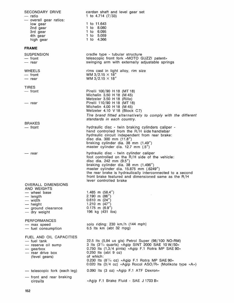
SECONDARY DRIVE - ratio - overall gear ratios:
low gear 2nd gear 3rd gear 4th gear high gear
FRAME
SUSPENSION - front - rear
WHEELS - front - rear
TIRES - front
- rear
BRAKES - front
- rear
OVERALL DIMENSIONS AND WEIGHTS - wheel base - length - width - height - ground clearance - dry weight
PERFORMANCES - max speed - fuel consumption
FUEL AND OIL CAPACITIES - fuel tank - reserve oil sump - gearbox - rear drive box
(level gears)
- telescopic fork (each leg)
- front and rear braking circuits
152
cardan shaft and level gear set 1 10 4.714 (7/ 33)
1 to 11.643 1 to 8.080 1 to 6.095 1 to 5.059 1 to 4.366
cradle type - tubular structure telescopic front fork "MOTO GUZZI patent» swinging arm with externally adjustable springs
rims cast in light alloy , rim size WM 3/2.15 X 18" WM 3/ 2.15 x 18"
Pirel li 100/ 90 H 18 (MT 18) Michelin 3.50 H 18 (M 45) Metzeler 3.50 H 18 (Ri lle) Pireili 110/ 90 H 18 (MT 18) Michelin 4.00 H 18 (M 45) Metzeler 4.10 V 18 (Block e7) Tire brand fitted alternatively to comply with the different standards in each country.
hydraulic disc - twin braking cylinders caliper -hand controlled from the R/ H side handlebar hydraulic circuit independent from rear brake: disc dia. 300 mm (11 .8/1 ) braking cylinde r dia. 38 mm (1.49") master cylinder dia. 12.7 mm (.5")
hydraulic disc - twin cylinder caliper foot controlled on the R/ H side of the vehicle: disc dia. 242 mm (9.5/1) braking cyli nder dia. 38 mm (1.496") master cylinder dia. 15.875 mm (.6249/1) the rear brake is hydraulically interconnected to a second front brake leatured and dimensioned same as the R/ H lever controlled brake
1.485 m (58.4" ) 2.190 m (86") 0.610 m (24") 1.210 m (47") 0.175 m (6.9" ) 196 kg (431 Ibs)
solo riding : 230 km/ h (144 mph) 6.5 Its km (abt 32 mpg)
22.5 Its (5,84 us gls) Petrol Super (98/ 100 NO-RM) 3 lis (3 1
/. quarts) «Agip SINT 2000 SAE 10 W/ 50" 0.750 Its (1,3/ 4 pints) «Agip F.1 Rotra MP SAE 90" 0.250 Its (abt 9 oz) of which: 0.230 Its (S 1/4 oz) "Agip F.l Rotra MP SAE 90" 0.020 lis (3/ 4 oz) «Agip Rocol ASO / R» (Mo likote type «A»)
0.090 Its (3 oz) «Agip F.1 ATF Oexron ...
«Agip F.1 Brake Fluid - SAE J 1703 B»
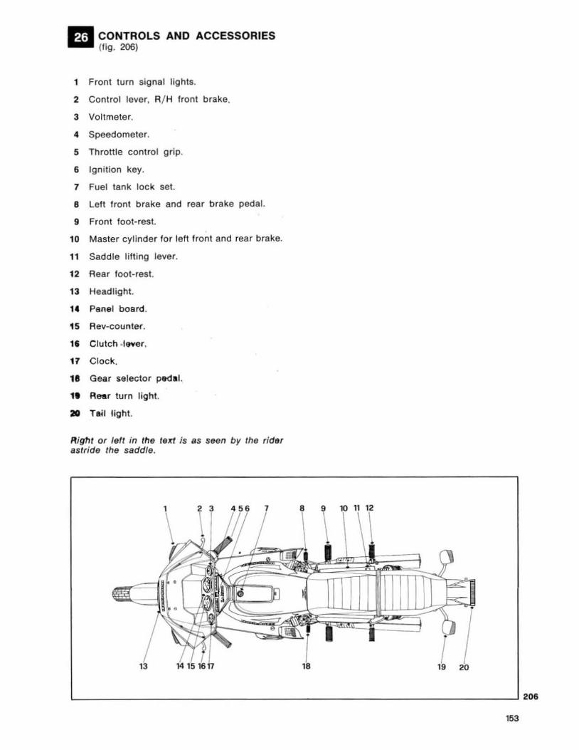
CONTROLS AND ACCESSORIES (fig. 206)
1 Front turn signal lights.
2 Control lever, R/ H front brake.
3 Voltmeter.
4 Speedometer.
S Throttle control grip.
6 Ignition key.
7 Fuel tank lock set.
B Left front brake and rear brake pedal.
9 Front foot-rest.
10 Master cylinder for left front and rear brake.
11 Sadd le lifting lever.
12 Rear foot-rest.
13 Headlight.
1C Panel board.
1S Rev-counter.
l' Clutch .Iever.
17 Clock.
18 Gear selector pedal.
1. Rear turn light.
210 Tail light.
Right or feft in the text is BS seen by the ,idar astride the saddle.
L-__________________________________________________________ ~20.
153
207
208
154
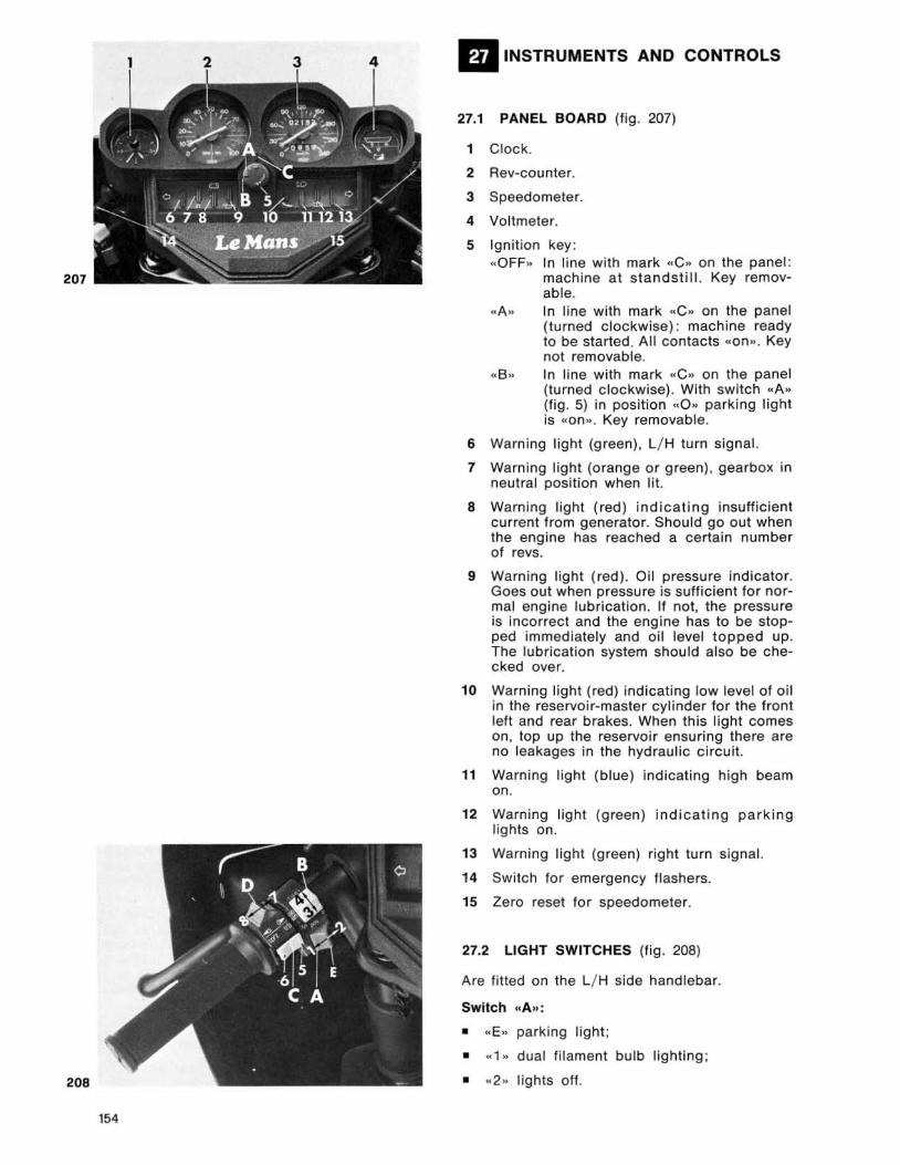
III INSTRUMENTS AND CONTROLS
27.1 PANEL BOARD (fig . 207)
1 Clock .
2 Aev·CQunler.
3 Speedometer.
4 Voltmeter.
S Ignit ion key : " OFF. In line with mark «C» on the panel :
machine at s tands t ill. Key removable.
" A.. In line with mark .. Coo on the panel (turned clockwise) : machine ready to be started , All contacts «on .. , Key not removable .
.. 8 .. In line with mark «C .. on the panel (turned c lockwise). With switch .. A .. (fig. 5) in positi on .. 0 .. parking light is "on ,. , Key removable .
6 Warning light (green) , L/ H turn signal.
7 Warning light (o rang e or green) . gearbox in neut ral position when l it.
a Warning light ( red) indicating insufficient current from generator. Should go out when the eng ine has reached a certa in number of revs.
9 Warning l ight (red). Oil pressure indicator. Goes out when pressure is sufficient for nor· mal engine lubrication. If not, the pressure is Incorrect and the engine has to be stop· ped immediately and oi l level topp ed up. The lubrication system should also be che· cked over.
10 Warning light (red) indicat ing low level of oi l in the reservoi r·master cyl inder for the front left and rear brakes. When this light comes on, top up the reservoir ensuring there are no leakages in th e hydraulic c ircuit.
11 Warn ing l igh t (blue) indicatin g high beam on.
12 Warn ing light (green) indicat ing parking l ights on.
13 Warning light (green) ri gh t turn signal.
14 Swi tch for emergency flashers.
15 Zero reset for speedometer.
27.2 LIGHT SWITCHES (fig . 208)
Are fitted on the L j H side handlebar.
Switch fC A»;
• .. E» parking light ;
• .. 1 " dual filament bulb l ight ing ;
• .. 2 .. lights off.
Switch .. B .. :
With switch .. A .. in position .. 1 .. :
• «3" low beam ;
• .. 4 .. high beam.
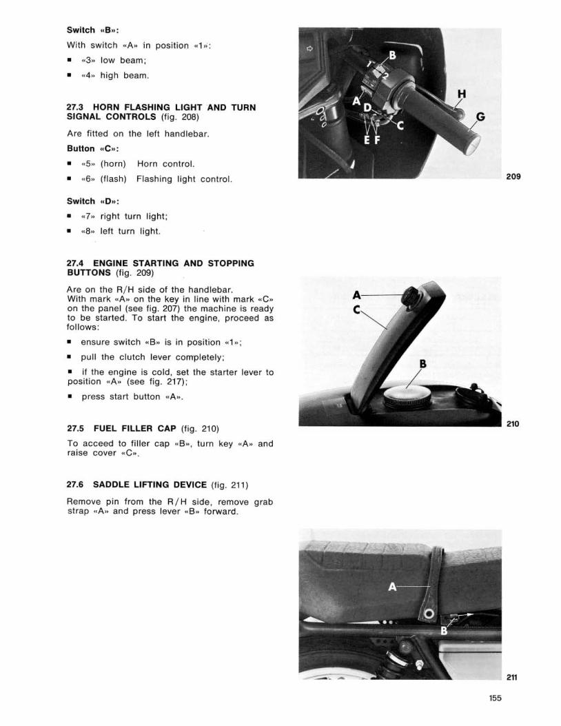
27.3 HORN FLASHING LIGHT AND TURN SIGNAL CONTROLS (fig . 208)
Are fitted on the left hand lebar.
Button etC .. :
• .. 5 .. (horn) Horn control.
• .. 6,. (flash) Flashing l ight conlrol.
Switch .. 0 ,.:
• .. 7,. r ight turn light ;
• «8 .. left turn l ight.
27.4 ENGINE STARTING AND STOPPING BUTTONS (fig. 209)
Are on the R/ H side of the handlebar. With mark " A .. on the key in line with mark .. C .. on the panel (see fig. 207) the machine is ready to be started . To sta rt the engine, proceed as follows :
• ensure switch .. 8 .. is in position «1,, ;
• pull the c lutch lever completely ;
• if the engine is cold , set the starter lever to posit ion .. A .. (see fig. 217);
• press start button "A., .
27.5 FUEL FILLER CAP (fig . 210)
To acceed to fi l le r cap .. 8 .. . turn key " A" and raise cover .. C .. .
27.6 SADDLE LIFTING DEVICE (fig . 211 )
Remove pin from the R / H side , remove grab strap "A .. and press fever ,,8 .. forward.
209
210
211
155

II CYLINDERS - PISTONS - PISTON RINGS
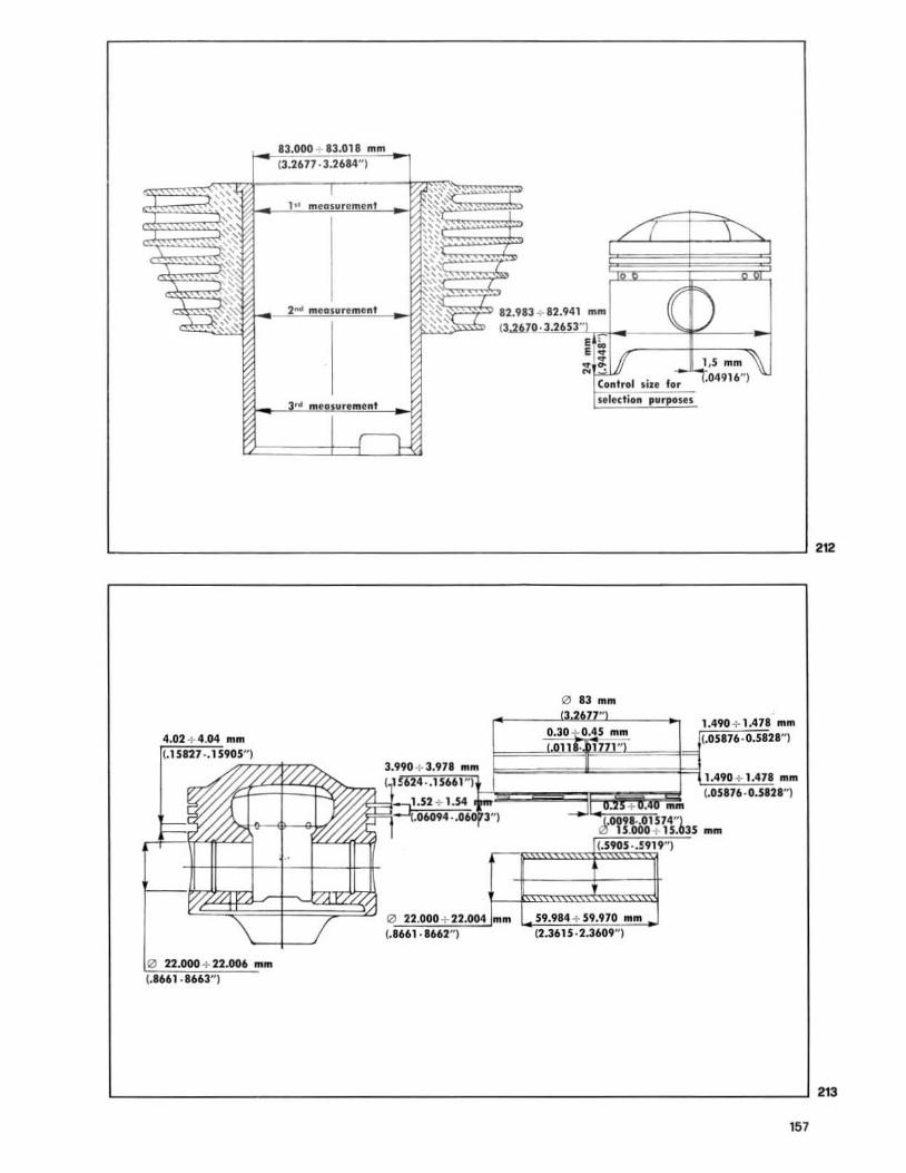
28.1 CYLINDERS (see fig . 212)
Inspection
The cylinder bore should be measured al 3 dif· ferent heights in a t ransversal and longitudinal directions (on top, at center, and at the base). Shou ld the steeve be worn down to more than the specified limits, it will be necessary to regr· ind the cy linder, bearing in mind that pistons and piston rings are available in the following oversizes: 4/ 10 (.01574") and 6/ 10 (0.02362" ).
CYLINDER
ORIGINAL 4f l0 mm 6 / 10 mm mm (.01574", (.02362")
83.000·83.018 83.400·83.418 83.600·83.618 (3.26n·3.2804 H
) (3.334-3.341 ~ ) (3.290-3.297")
SELECTION OF CYLINDER DIAMETER
ClASS .,... CLASS _8 . mm mm
83.000-83.009 83.009-83.018 (3.2677-3.2678 H
) (3.2678-3.2681 " )
N. B. Cylinders must always be matched with pistons of same class.
28.2 PISTONS (see fig . 212 and 213)
At the time an engine is overhauled the piston crown and the piston ring slots should be clea-
. ned of all ca rbon deposits before checking piston-cyl inder clearance. If this exceed the limits indicated in the table, then it will be necessary to regrind the cyli nder bearing in mind that the pistons are supplied in the following oversizes : 4/ 10 (.01574 ") 6 / 10 (.02362"). For engine balancing, both pistons should be the same weight. The maximum admissible difference should never exceed 1.5 grams (.05 oz) . The selection measurement should be taken at 22 mm (.0866") from the piston base (see drwg fig. 349 and select ion table) . When fitt ing a piston, take note of the selection mark stamped on the piston, also that word ing .. SCA" (exhaust) is turned against the cylinder exhaust port.
PISTON
ORIGINAL 4/ 10 ... m S/ lD ...... mm 1.0151.", (·0Zl62·1
82.923-82.941 83.325-83.341 83.523-83.541 (3.2646-3.26S:n (3.2804.3.2811 N) (3.2883-3.2889N)
156
SELECTION OF PISTON DIAMETER
CLASS ·A_ CLASS . 8 · mm mm
82.923-82.932 82.932-82.941 (3.2646-3.2650") (3.2650-3.2£S4~)
N.B. Pistons must always be matched with cylinders of same class ( <<A» with «A», "B .. with «B»).
28.3 FITTING THE PISTON ON CON-ROD
Before re-fitting the piston on the con-rod, heat it up in an oil bath at about 60 "C (140 OF) to l igh tly expand the hole and so make introduction of the piston easier.
28.4 PISTON PIN - PISTON HOLE CLEARANCES (see dfWg n. 213)
Each piston fits 3 piston rings :
1 Top compression ring
Original production 0 83.000 mm (3.267 ")
- 0 0 / 54/ 10 mm (.01574") 83.400 mm (3.282" )
- 0 0/ 56/ 10 mm (.02362") 83.600 mm (3.291")
Piston ring thickness 1.490- 1.478 mm (.05866- .0581 8") Piston ring gap 0.30-0.45 mm (.0118 - .0177" )
Piston ring thickness - piston groove clearance 0.030-0.062 mm (.0011 - .0024")
2 Intermediate stepped oil scraper
Original production 0 83.000 mm (3.267")
- 0 0/ 54/1 0 mm (.01574") 83.400 mm (3.282")
o 0 / 56/ 10 mm (.02362") 83.600 mm (3.290" )
- Piston ring thickness 1.490- 1.478 mm (.05866- .05818")
- Piston ri ng gap 0.30-0.45 mm (.0118 -.0177")
- Piston ring thickness - piston groove clearance 0.030 -0.062 mm (.0011-.0024" )
3 Bottom 011 scraper with spiral
- Origina l production 0 83.000 mm (3.267")
o 0/ 54/ 10 mm (.01574") 83.400 mm (3.282 ")
0 0/ 56/ 10 mm (.02362" ) 83.600 mm (3.291")
Piston ring thickness 3.900-3.878 mm (.153- .146")
Piston ring gap 0.25-0.40 mm (.0098- .015")
Piston ring thickness - piston groove clearance 0.042-0.060 mm (.0016-.0023")
83000 83018 mm 13.2677 ·3.2684"1
,,, meD ~lIremen t
,,,- , --" 1" ~~'..' - -. '~~ " " " ", " ," ,
'" ", '" " '" , ", " " .
" " '"'' ~ " , '" ~, ~ ,~ 2- meDlUrl meftt " 12,9
~ ~ " ~, :::~~~ ~ ~
, .. eD II eml nt
-rI-
4.02 + 4.04 mm
(.1 5127 .. 159;O?'7"1z,'7I7Z~ 3.990 + 3.971 mm ( 1~62 ·.15661")
1.52 + 1.S4
o 22.000 + 22.006 mm (.8661 · 8663,,)
.06094 •. 060 3'1
'" 22.000 + 22.004 mm " (,8661 . 8662 )
13 + 82.941
o 83 mm
0.30 0.45 mm
+ . nom
"",,' ·."'74"1
1.490 + 1.478 mm (.OS876 ·0.S828'1
1.490 + 1.478 mm (.05876 ·0.Sl2ln
)
o 15 000 + 15 035 nom (.S9OS · .5919")
59.984 + S9.970 mm " (2.3615 2.3609 )
157
212
213
""."S ~ 140 .02S mm
parallelism and t amplo. narity difference between the two axis measlIred at 200 :!: 0.10 mm
214 L _______________ -'
158
m CON-RODS - CRANKSHAFT
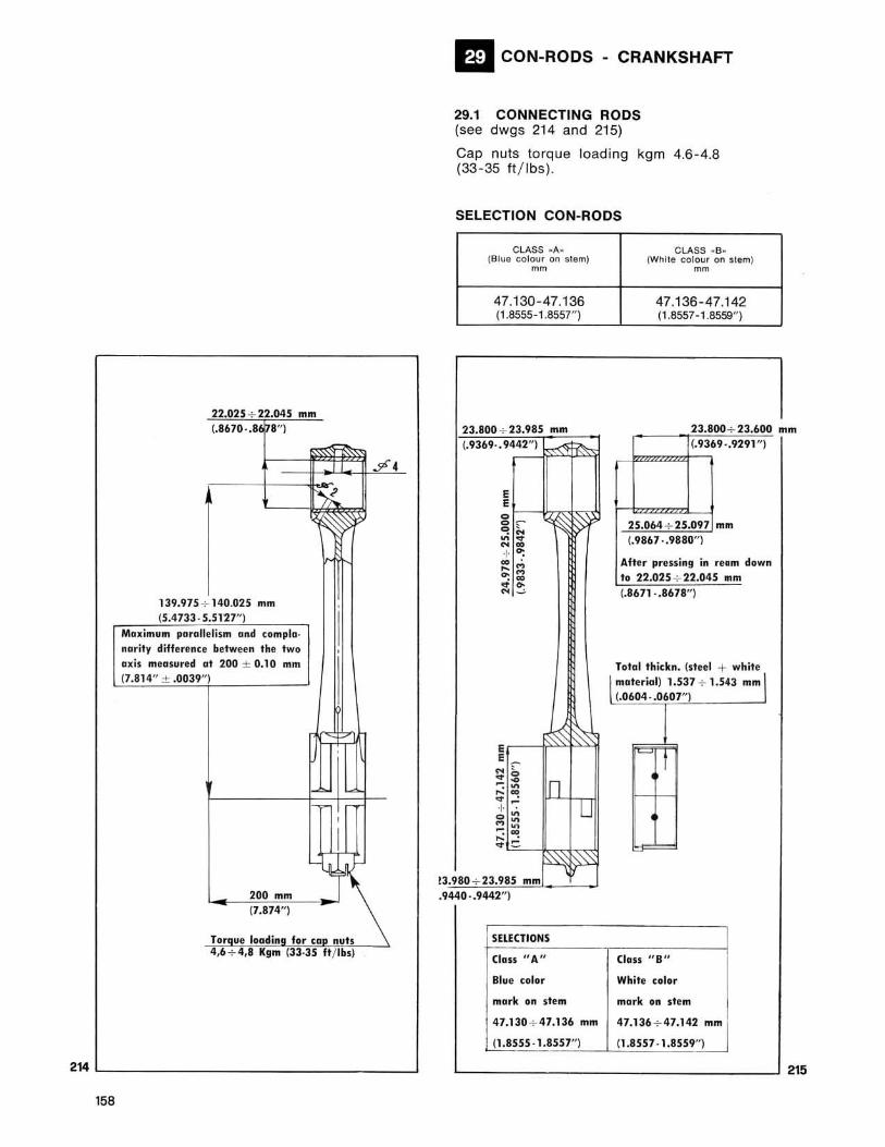
29.1 CONNECTING RODS (see dwgs 214 and 215)
Cap nuts torque load ing kgm 4.6 -4.8 (33 -35 ft j lbs) ,
SELECTION CON· RODS
CLASS _A. lSlue colo'" on Slem)
mm
47.130-47.136 (1.8555-1.8557" )
23.800 : 23.985 mm (.9369. , 9442")
E E e
~ e ~ e • • N ~ . N ~ + <>: ~ . ~M .M . ~ :!; ~
~ ~ E E "" , In . 0 -~ . ~ ~~
.~
IU + . gE ~~ ~ . . -
3.980 : 23.985 mm , .9440 -.9442")
SELECTIONS
(Ian" A"
Blue color
mark on stem
47.130 + 47.136
(1.8555 ·1 .8557")
mm
CLASS . 8 . lWhile colou' on stem)
mm
47.136 -47.142 (1.6557- 1.8559")
23.800 : 23.600 m (.9369 -.9291 ")
25.064 : 75.097 mm (.9867 · ,9880")
Afte r prenin9 in ream down 10 22.075 : 22.045 111m (.8671 · .8678" )
\ Talcd thickn. (steel + whit: I materia l) 1.S37 + 1.543 mm (.O604 · .0607"
Class " 8 "
White color
mork on stem
47.136 + 47.142 mm
(1.8557 · 1.8559")
m
215
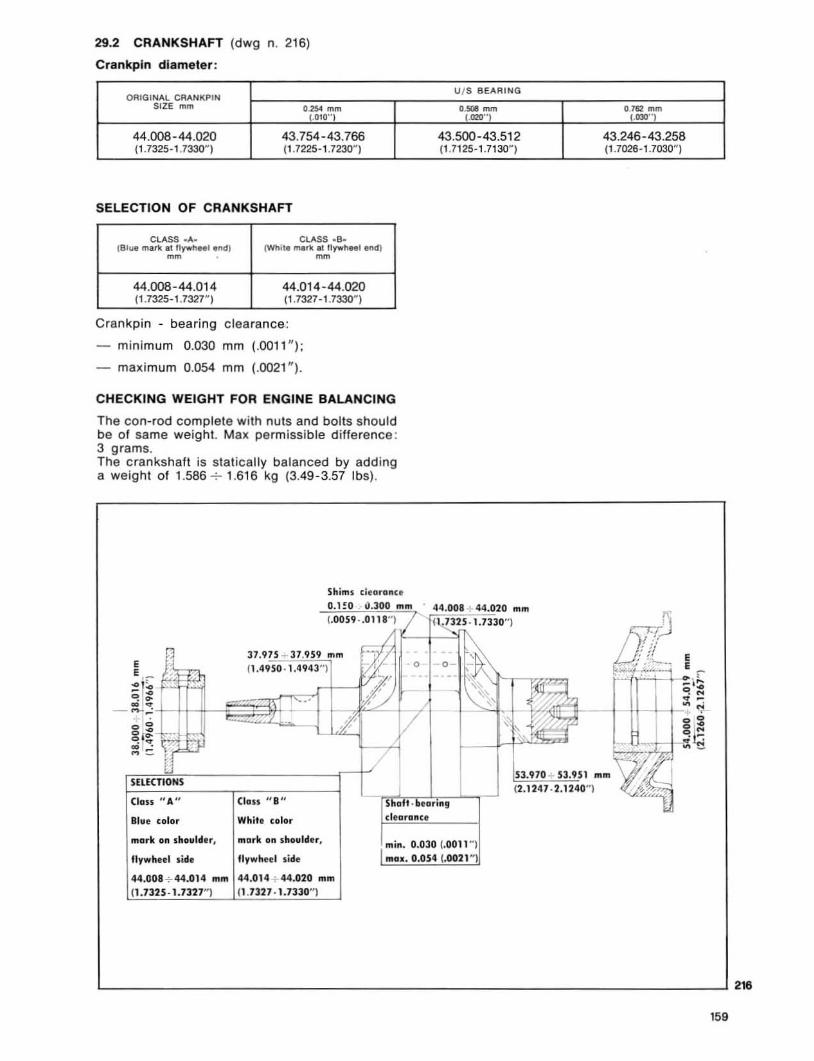
29.2 CRANKSHAFT (dwg n. 216)
Crankpln diameter:
ORIGINAl. CRANKPIN SIZE mm 0.2:54 mm
(.010"1
44.008-44.020 43.754-43.766 ( 1 . 7325·1 .7330~ 1 ( 1 . 7225- 1 . 7230~ )
SELECTION OF CRANKSHAFT
ClASS . A_ CLASS .S. lS I.,. mark al 1IY"'1>H1 _I (WtIite me.1t III lI)'Wt'leeJ enet)
mm mm
44.008-44.014 44.01 4-44.020 (1.7325, ' .732r) ( 1 . 7327 - 1 . 7330~ )
Crankpin - bearing clearance:
minimum 0.030 mm (.0011 " );
maximum 0.054 mm (.0021 ").
CHECKING WEIGHT FOR ENGINE BAlANCING
The con-rod complete with nuts and bolts should be of same weight. Max permissible difference : 3 grams. The crankshaft is statica lly balanced by add ing a weight of 1.586 -:- 1.616 kg (3.49-3.57 Ibs).
Shims dnron,e OltO -:1300 . . mm
(.0059 · .01 18""J ,/
i 37.975 .. 37.959 mm E 0.4950 . 1.4943") 0 E , "
:;!
U / S 8EARING
a.- mm (.02(1"1
43.500-43.512 ( ' .7125- 1 . 7130~)
. 44.008 + 44.020 mm
tl ~25 . , .7330"1
o~ - -- ~ Z -r ~ I~, . /'/ I-.. :: .. I .
-" - Li' / g,: . , , ..; I"': .- /
fi , :J
~ SEUCTIONS
3.910 + 53.9 l2.J247 .2.J24
(lass " A" (loss " S" S II t ' II'II""9
Bill' colllr Whit, clllllr d'lIron(,
mark on shollldtr. mllrk on shovlder. min. 0.030 (.0011 ")
flywheel side flywheel side mOll. 0.054 (.0021 ~)
44.008 + 44.014 mm 44.014 + 44.020 mm (1 .7325 · 1.7327") 0 .7327 · 1.7330")
0-162 mm (.030"1
43.246-43.258 ( 1 . 7026·1 .7030~)
L-______________________________________________________________ -" 21.
159
217
160
m CARBURATION
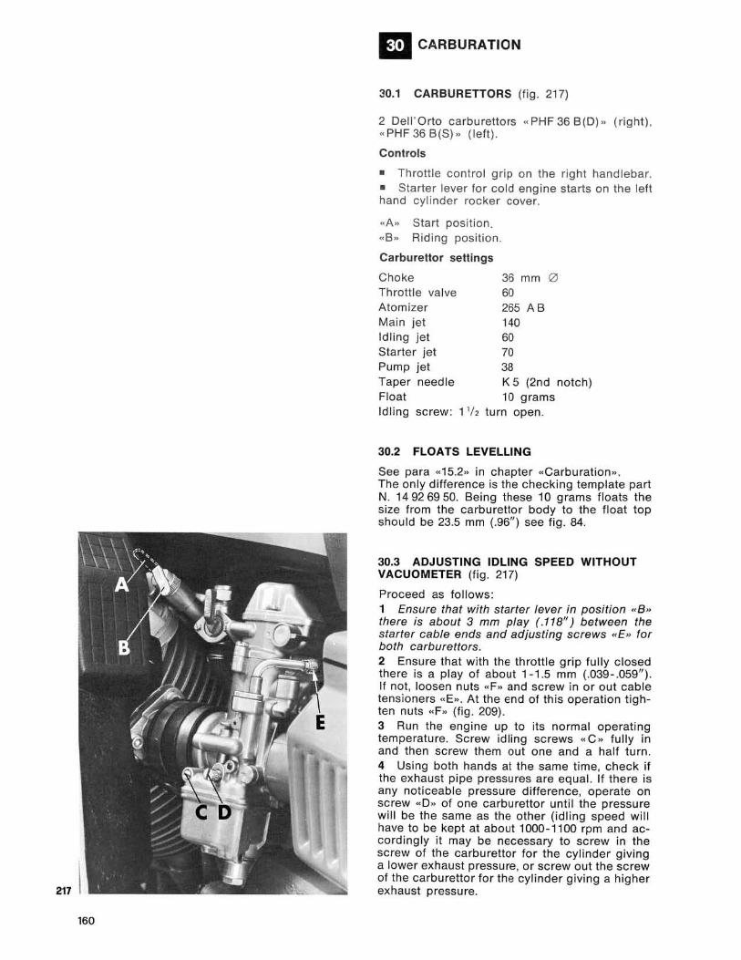
30.1 CARBURETTORS (fig . 217)
2 Dell' O rto carburetto rs " PHF 36 8(0 )>> ( r ight), .PHF 368(8). (lel1).
Controls
• Throttle control grip on the right handlebar. • Starter lever for col d eng ine starts on the left hand cyli nder rocker cover .
.. A" Slart position .
.. 8.. Riding position.
Carburettor settings
Choke Throttle valve Atomizer Main jet Idling jet Starter jet Pump jet Taper needle Float
36 mm 0 60 265 A B 140 60 70 38 K 5 (2nd notch) 10 grams
Idling screw : 1 112 turn open.
30.2 FLOATS LEVELLING
See para «15.2» in chapter "Carburation». The only difference is Ine checking template part N. 14926950. Being these 10 grams floats the size from the carburettor body to the float top should be 23.5 mm (.96/1) see fig . 84.
30.3 ADJUSTING IDLING SPEED WITHOUT VACUOMETER (fig . 217)
Proceed as follows: 1 Ensure that with starter lever in position «8 » there is about 3 mm play ( .118/1) between the starter cable ends and adjusting screws «E» for both carburettors. 2 Ensure that with the throttl e grip fully closed there is a play of about 1- 1.5 mm (.039-.059" ). If not , loosen nuts «F" and sc rew in or out cable tensioners «E». At the end of this operation tighten nuts «F» (fig . 209) . 3 Run the engine up to its normal operating temperature. Screw idling screws «C o> full y in and then screw them out one and a half turn. 4 Using both hands at the same time, check if the exhaust pipe pressures are equal. If there is any noticeable pressure difference, operate on screw «0" of one carbu rettor until the pressure wil l be the same as the other (idl ing speed w ill have to be kept at about 1000-1100 rpm and accordingly it may be necessary to screw in the screw of the carburetlor for the cy linder giving a lower exhaust pressure, or screw out the sc rew of the carburetlor for the cylinder giving a higher exhaust pressure.
S Acting on screws .. C .. obtain the best carbu· ration for each cylinder (this will be noticed by a slight increase of rpm) and adjust the tick-over speed according to point 4. 6 Disconnect one spark plug lead at a time and check that th e engine in both cases stops after firing the same number of strokes. If this does not occur, screw out screw .. 0 .. of the carburettor for the cylinder that makes the engine fire more strokes or screw in the screw of the ca r· burettor making the engine fire less strokes. 7 Adjust id l ing speed at 1000·1 100 rpm by screwing in or out both screws .. 0 » by the same amount. 8 Ensure that the sl ides open simultaneously by proceed ing as follows : by the assistance of a second person, gradually turn the throttle can· trol grip and check that. the exhaust pipe pressure increases in synchron izat ion, using both your hands. If the pressure inc rease of one cylinder is advanced, act on it s carburettor by gra· dually sc rewing in adjuster .. E .. after loosening counternut .. F .. (fig. 209) unti l the synchronization of both exhaust pipe pressures is reached.
30.4 CHECKING THE CARBURATION WITH A VACUOMETER
Proceed as follows:
1 Make sure that with starter lever in the .. 8 .. position there is a c learance of about 3 mm (.118") between the starter cable ends and the wi re adjusting sc rews .. E .. of both carburettors (fig. 217) . 2 Ensure that with the twi s t grip fu lly c losed between the cable ends and cable adjusters .. E» (at the handlebar end) there is a clearance of 1·1.5 mm (.039-.059") fo r both carburettors. If not, loosen counternuts .. F .. and sc rew in or out adjusting screws .. E .. not forgetting to re-tighten nuts .. F .. after adjustment (see fig . 209) . 3 Adjust sc rew .. C .. (Iig . 217) screwing it in fully and then unscrewing it 1 '12 turns for both carburetto rs. (Undoing th is screw increases the petrol flow and viceversa decreases it) . 4 Remove in let pipe .. A .. sealing plugs and in the holes fit up hoses .. 8 .. of vacuometer .. C. (see fig . 85). S To adjust the tick-over speed (to be done on a warm engine) operate as follows: • start the engine with the throttle grip at minimum opening (1000· 1100 rpm) operating on slide adjuster .. 0 .. in fig. 217. At this stage, check that both mercury columns .. 0 .. of vacuometer .. C .. (fig . 85) are at same height and, if not act on screw .. 0 .. (fig. 217) to obtain this condition. 6 Re-adjust the positions of pi lot screws .. C .. (fig . 217) to the point giving the lowest possible number of revolutions. Then re-check the position of both mercury columns .. 0 .. on vacuo meter dial .. C .. (fig . 85) and eventually repeat lIJe operation at 5. 7 Synch ronize the ca rburettors as follows (after adjusting idl ing speed) : • start the eng ine and grad uall y acce lerate, checking that both mercury columns on vacuo-
meter dial .. C .. are equally l ined up (fig. 85) . If not, operate on cable adjusters .. E .. after having loosened counte rnuts .. F .. (see fig. 209) of the throttle control cables (handlebar end) until the said line up is obtained ; • after th is check, undo the hoses from the inlet ports .. B» (fig. 85) and ret ighten all retaining screws and washers.
161
21.~ __ _
162
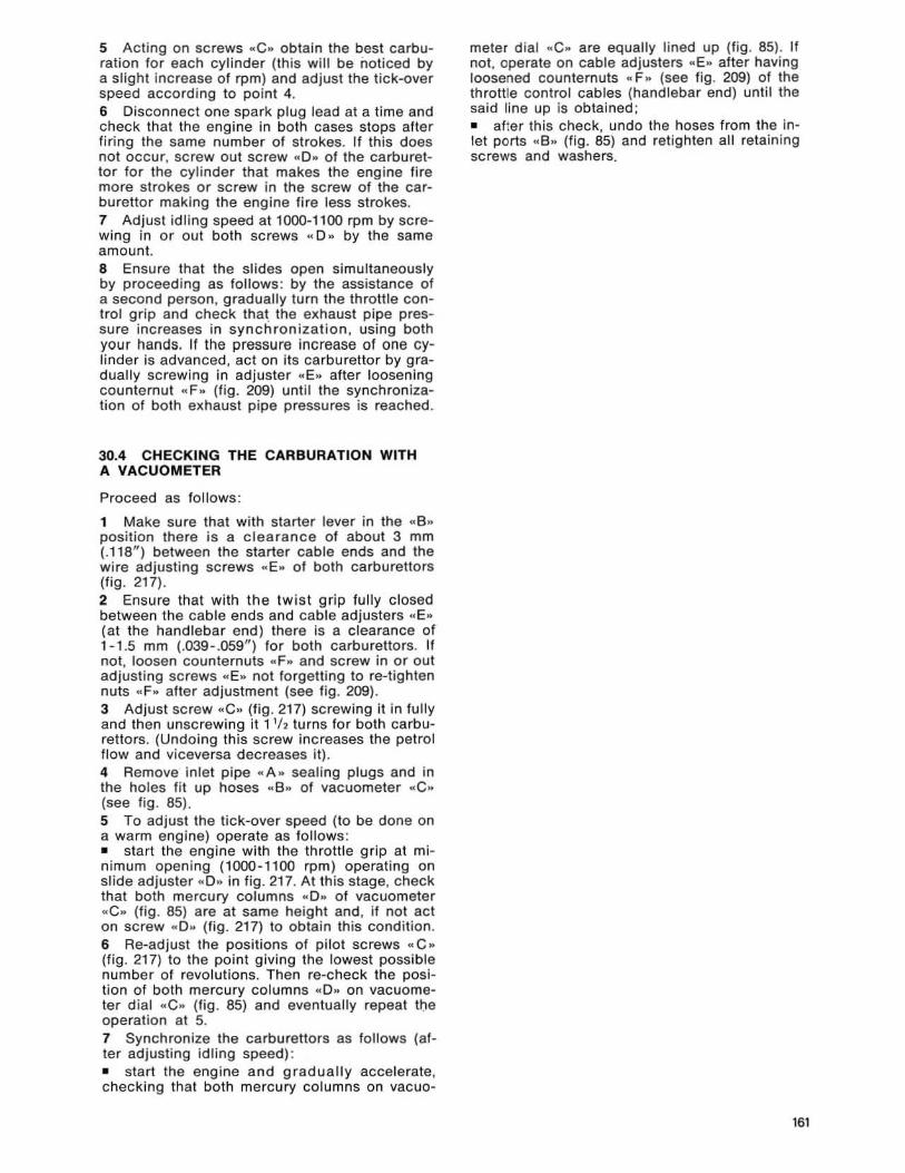
30.5 CARBURETTOR COMPONENTS
1 Throttle valve (sl ide) . 2 Needle K. 3 Main nozzle AB. 4 Main jet. 5 Pilo t jet. 6 Starter jet. 7 Accelerator pump jet . 8 Float needle valve . 9 Float unit.
10 Top cover screw. 11 Gasket. 12 Throttle control lever screw. 13 Washer. 14 Top cover. 15 Cover gasket . 16 Washer. 17 Throttle sl ide crank . 18 Intermediate slide control cable. 19 Support screw. 20 Washer. 21 Support. 22 Mixture chamber cover screw. 23 Chamber cover. 24 Lever washer. 25 Lever cap cover. 26 Lever return spring. 27 Throttle gas lever. 28 Return spring. 29 Needle c lip. 30 Gasket, mixture chamber cover. 31 Pin , accelerator pump lever. 32 Spring. 33 Throttle pump arm. 34 Tube. 35 Cable adjuster securing screw. 36 Cable adjuster. 37 Starter cable cap. 38 Slarter cover screw. 39 Starter cover. 40 Cover gasket. 41 Starter valve return spring. 42 Starter valve. 43 Idle adjuster washer. 44 Washer, flat . 45 Idle adjusting screw spring. 46 Idle screw. 47 Throttle va lve (sUde) adjusting screw. 48 Throtlle valve spring. 49 Flat washer. 50 Washer. 51 Accelerator pump jet holder. 52 Jelholder washer. 53 Washer. 54 Accelerator pump valve. 55 Pump diaphgram screw washer.
56 Pump diaphgram screw. 57 Diaphgram securing nul. 58 Accelerator pump cover screw. 59 Washer. 60 Pump cover. 61 Pump diaphgram spring. 62 Pump diaphgram. 63 Pump diaphgram gasket. 64 Main jetholder. 65 Filter screen. 66 Petrol feed union. 67 Union screw. 68 Accelerator pump leeder. 69 Needle gasket. 70 Float pivot pin . 71 Sealing gasket. 72 Float bowl. 73 Float bowl plug gasket . 7' Float bowl plug. 75 Air intake tube. 76 Pin, throttle control. T7 Pin return spring. 78 Cover, mixture chamber.
163
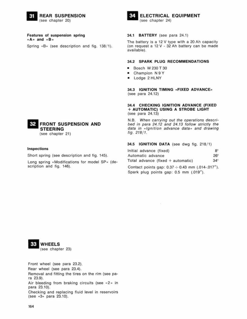
~ REAR SUSPENSION .... (see chapter 20)
Features of suspension spring .. A .. and "e .. Spring .. 6 . (see description and fig . 138/ 1).
II FRONT SUSPENSION AND STEERING (see chapter 21)
Inspections
Short spring (see description and fjg. 145).
Long spring .. Modifications lor model SP .. (desc ription and fig . 146).
mWHEELS (see chapter 23)
Front wheel (see para 23.2) , Rear wheel (see para 23.4), Removal and fitting the tires on the rim (see para 23.9) , Air bleeding from brak ing circuits (see .. 2. in para 23.10). Checking and replacing fluid level in reservoirs (see .. 3 .. para 23.10) .
164
II ELECTRICAL EQUIPMENT (see chapter 24)
34.1 BATTERY (see para 24.1)
The battery is a 12 V type with a 20 Ah capacity (on request a 12 V - 32 Ah battery can be made available) .
34.2 SPARK PLUG RECOMMENDATIONS
• Bosch W 230 T 30 • Champion N 9 Y • lodge 2 HlNY
34.3 IGNITION TIMING .. FIXED ADVANCE .. (see para 24.12)
34.4 CHECKING IGNITION ADVANCE (FIXED + AUTOMATIC) USING A STROBE LIGHT (see para 24.13)
N.B. When carrying out the operations descri· bed in para 24.12 and 24.13 follow strictly the data in .. Ignition advance data .. and drawing fig. 218/ 1.
34.5 IGNITION DATA (see dwg fig . 218/ 1)
Initial advance (fixed) 8" Automatic advance 26" Total advance ('Ixed + automatic) 34°
Contact points gap: 0.37 ..;.- 0.43 mm (.0"1 4· .017" ). Spark plug paints gap : 0.5 mm (.01 9" ).
II 35.1
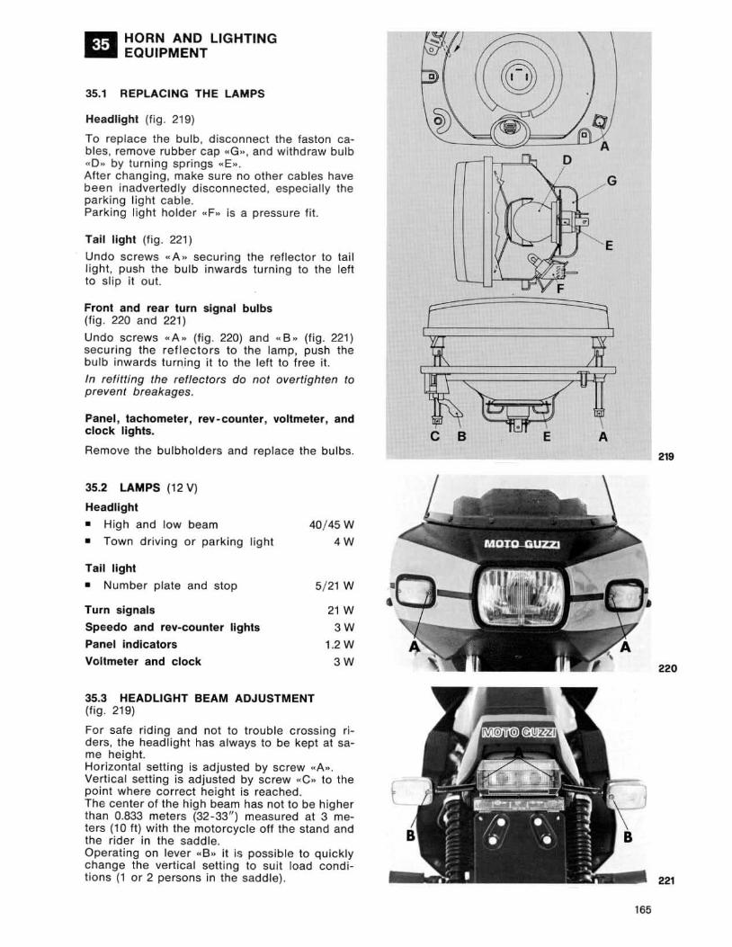
HORN AND LIGHTING EQUIPMENT
REPLACING THE LAMPS
Headlight (fig . 219)
To replace the bulb. d isconnect the faston cables , remove rubber cap .. G». and withdraw bulb .. D .. by turning springs «E», After changing. make sure no other cables have been inadvertedly disconnected, espec ially the parking light cable. Parking light holder .. F,. is a pressure fit.
Tail light (f ig . 221)
Undo screws ... A .. securing the reflector to tail lighl , push the bulb inwards turn ing to the left to Sli p it out.
Front and rear turn signal bulbs (fig. 220 and 221)
Undo screws " A .. (fig . 220) and .. B " (fig . 221) securing the reflectors to the lamp, push the bulb inwards turning it to the left to free it.
In refitting the reflectors do not overtighten to prevent breakages.
Panel , tachometer, rev-counter, voltmeter, and clock lights.
Remove the bulbholders and replace the bulbs.
35.2 LAMPS (12 VI
Headlight
• High and low beam
• Town driving or parking light
Tail light
• Number plate and stop
Turn signals
Speedo and rev-counter lights
Panel indicators
Voltmeter and clock
40/ 45 W
4W
5/ 21 W
21 W
3W 1.2 W
3W
35.3 HEADLIGHT BEAM ADJUSTMENT (fig . 219)
For safe riding and not to trouble crossing ri ders, the headlight has always to be kept at same height. Horizontal setting is adjusted by screw .. A .. . Vertical setting is adjusted by screw .. C .. to the point where correct height is reached. The cen ter of the high beam has not to be higher than 0.833 meters (32-33") measured at 3 melers (10 tt) with the motorcycle off the stand and the rider in th e saddle. Operat ing on lever ,,8 .. it is possible to qu ickly change the vertical setting to suit load condilions (lor 2 persons in the saddle).
D
C B A
219
220
l
221
165
166
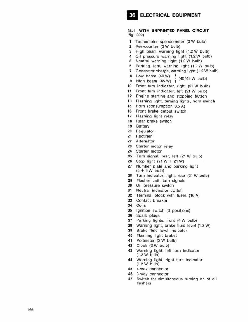
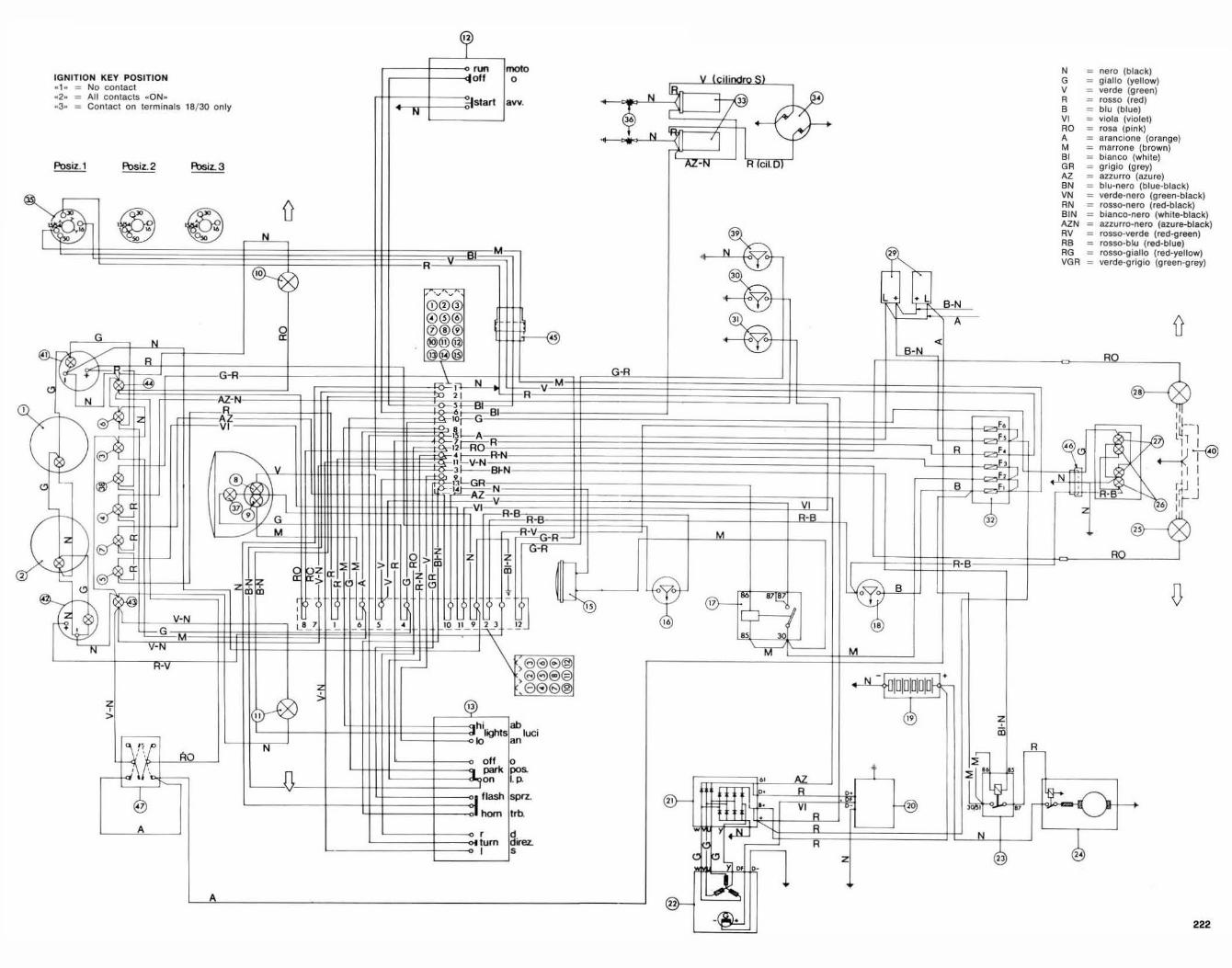
ELECTRICAL EQUIPMENT
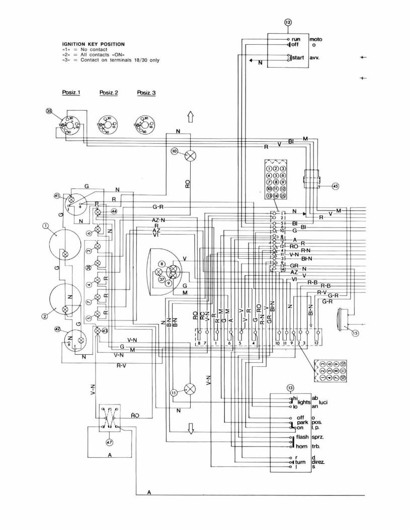
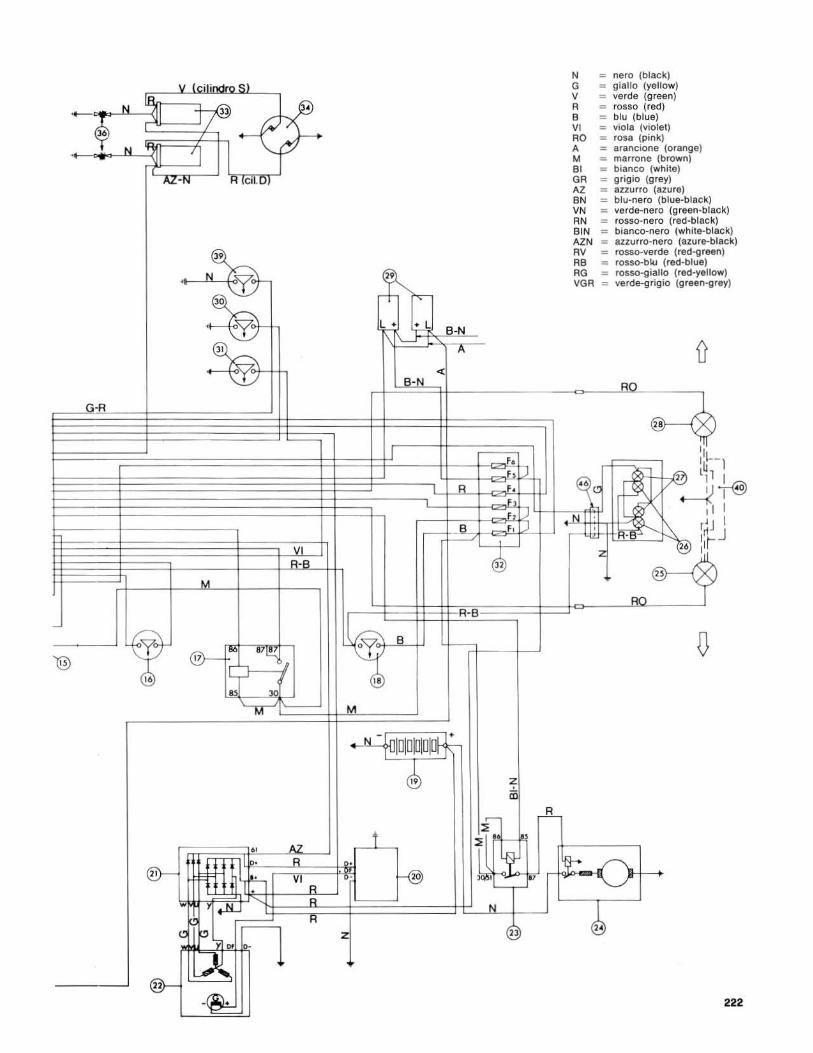
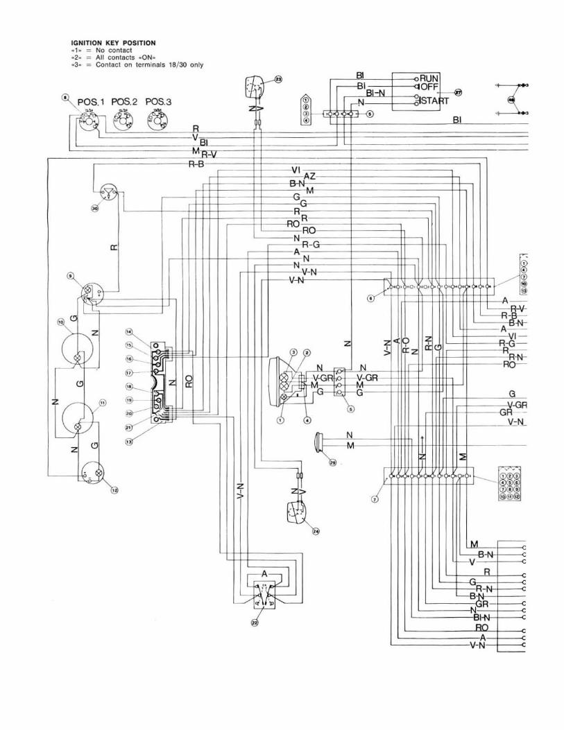
36.1 WITH UNPRINTED PANEL CIRCUIT (f;g. 222)
1 Tachometer speedometer (3 W bulb) 2 Rev-counter (3 W bulb) 3 High beam warning light (1.2 W bulb) 4 Oil pressure warning light (1.2 W bulb) 5 Neutral warning light (1 .2 W bulb) 6 Parking light, warning light (1.2 W bu lb) 7 Generator charge, warning light (1.2 W bulb)
8 L~w beam (40 W) ~ (40/ 45 W bulb) 9 H1gh beam (45 W) ~
10 Front turn ind icator, r ight (21 W bulb) 11 Front turn ind icator, left (21 W bulb) 12 Engine starting and stopping button 13 Flashing light, turning lights, horn switch 15 Horn (consumption 3.5 A) 16 Front brake cutout switch 17 Flashing light relay 18 Rear brake switch 19 Battery 20 Regulator 21 Rectifier 22 Alternator 23 Starter motor relay 24 Starter motor 25 Turn signal, rear, left (21 W bulb) 26 Stop l ight (21 W + 21 W) 27 Number plate and parking l ight
(5 + 5W bulb) 28 Turn indicator, right, rear (21 W bulb) 29 Flasher unit, turn signals 30 Oil pressure switch 31 Neutral indicator switch 32 Terminal block with fuses (16 A) 33 Contact breaker 34 Coils 35 Ignit ion switch (3 positions) 36 Spark plugs 37 Parking lights, front (4 W bulb) 38 Warning light , brake fluid level (1 .2 Wl 39 Brake flu id level indicator 40 Flashing l ight braket 41 Voltmeter (3 W bulb) 42 Clock (3 W bulb) 43 Warning light , left turn ind icator
(1.2 W bulb) 44 Warning light, right turn Indicator
(1.2 W bulb) 45 4-way connector 46 3-way connector 47 Switch fo r simultaneous turning on of all
flashers
I
,
IGNITION KEY POSITION ~ 1 · ::: NO contact - 2 - '" All con tacts . ON_ · 3- = COntac t on terminals 18/ 30 only
G
"" tx: R
C V ltL
I' " ~I >I '- ~ 1e1
c I~ ~ '"
C 1\ IE>"E
12
1&
~V --0 '" .... I, ~
~~~ ~ "
v-
z , >
V-N
G
I-V
G-R
•
N
R
~ ~
off
:;Istart
M
I , I H -
:'~G BI
~I--A
z
moto 0
avv.
V M R
<$
'i!!
N
N
W @
w
"
B-N
F. FI
---B- F.
F,
r-----' - @
M
R-B
~ B
®- " "i\
IT @
M ~
, . - IDIDJ1D~
4 z in
I" ~ • l-
II ~ , ~
--"-, @J
~
,
N = nero (black) G = g lallo (yellow) 1/ = verde (green) R = fosse (red) B = blu (blue) VI "" vio la (violet) RO ::: rosa (pink) A = aranclone (orange) M = mlrrona (brown) 81 = blarlco (white) GR = g. lgio (grey) AZ = auurro (azu re) BN = blu-nero (blue-black) liN = verde-nero (green-black) AN :: rosso-nero (red-black) BIN = bianco-naro (white-black) AZN = azzurro-nero (azure-black) RII = rosso-verda (red.green) RB = rosso-blu (red-blue) RG '" rosso-giallo (red-yellow) VGA = verde-grigio (green-grey)
D RO
r!.i
, , ,
D
~O t---+
~
222
IGNITION KEY POSITION - , - '" No contact _2_ = AU con tacts -ON--3- '" Contact on termlnats t8/ 3O only
H"
A
N
N
C'i> N
G-R
v . . ) S)
J? .-f3!-. ' I 'j
cn.u/
-
M
IJ M M
H 2
®- -~
"
t
< . B-N
R-B
-
F. F F.
F,
N '" nero (black) G '" glallo (yellow) v '" verde (green) R '" rOS50 (red) B '" blu (blue) VI = viola (violet) RO '" rosa (pink) A '" arancione (orange) M :: marrooe (brown) BI = blanco (white) GR '" grigio (grey) AZ '" auurro (azure) BN = blu-oero (blue-black) VN = verde-nero (greeo-black) RN :: rosso-nero (red-black) BIN '" bianco-nero (white-black) AZN = anurro-oero (azure-black) RV '" rosso-verde (red-green) RB '" rosso-blu (red-blue) RG = rosso-giallo (reel-yellow) VGR '" verde-grigio (green-grey)
HO
2
222
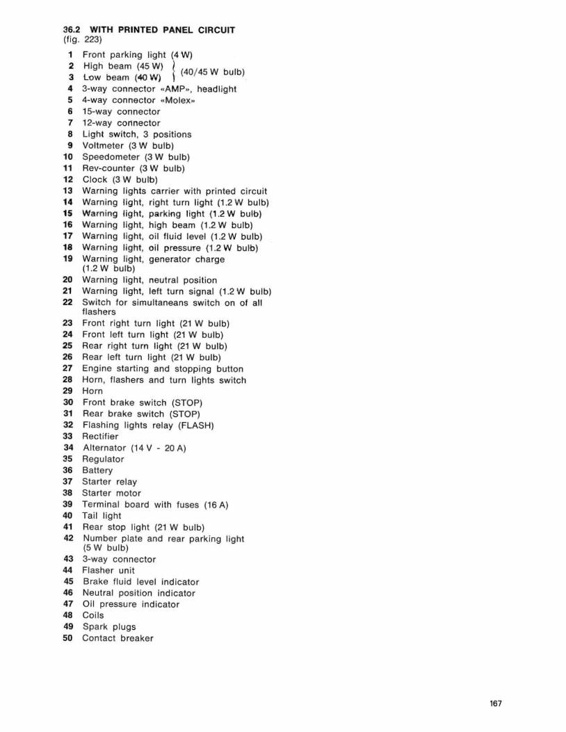
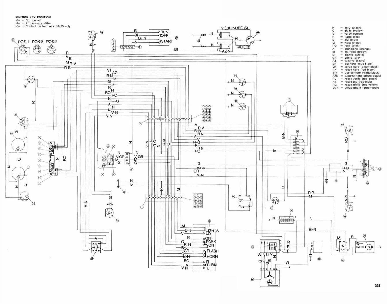
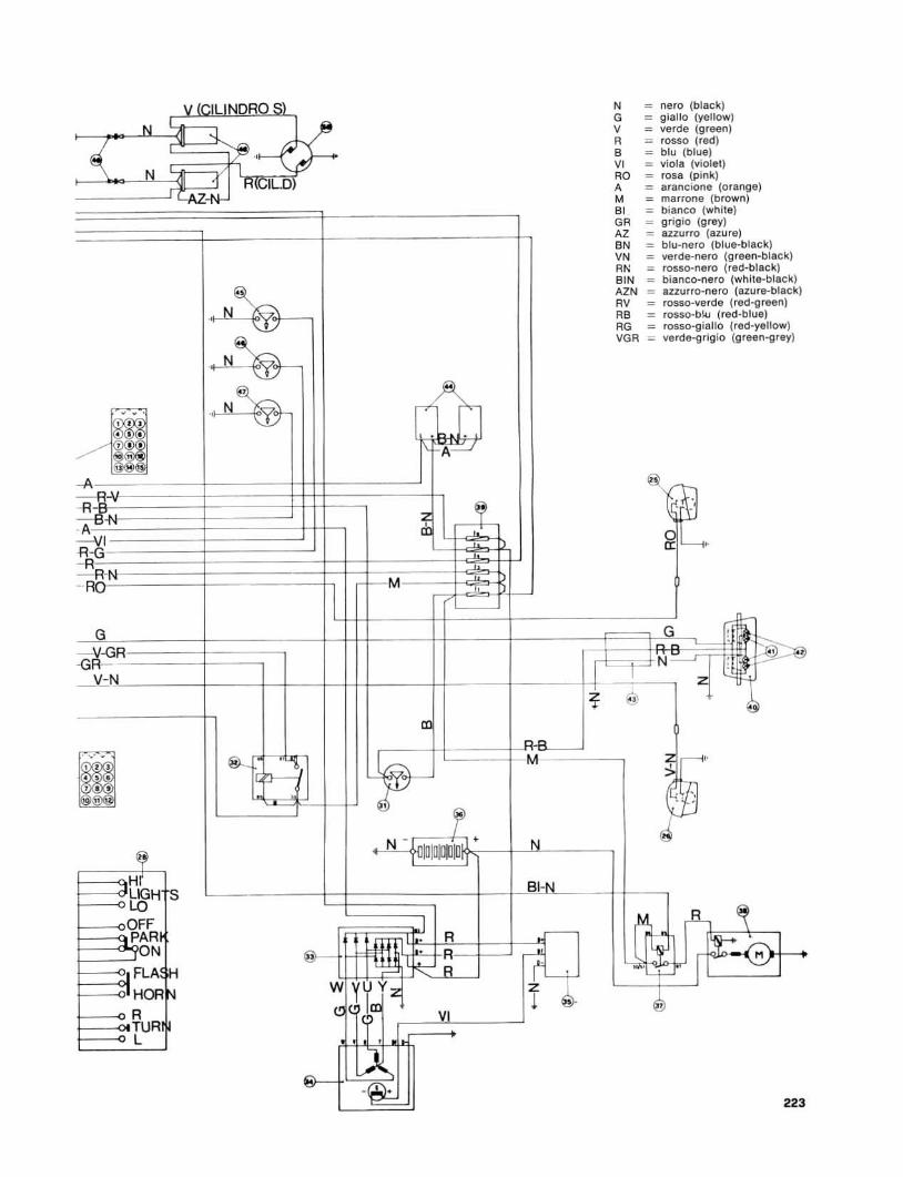
36.2 WITH PRINTED PANEL CIRCUIT (fi g. 223)
1 Front parking l ight (4 W)
2 High beam (45 W) l (40/ 45 W bu lb) 3 low beam (<40 W) , 4 3-way connector "AMP", headlight 54-way connector «Molex» 6 15-way connector 7 12-way connector 8 Light sw itch , 3 positions 9 Voltmeter (3 W bulb)
10 Speedometer (3 W bulb) 11 Rev-counter (3 W bulb) 12 Clock (3 W bu lb) 13 Warning lights carrier with printed ci rcuit 14 Warning light, right turn light (1 .2W bulb) 15 Warning light, parking light (1.2 W bulb) 16 Warn ing light. high beam (1.2 W bulb) 17 Warning light, oi l fluid level (1.2 W bulb) 18 Warning light, oil pressur e (1.2 W bu lb ) 19 Warning light , generator charge
(1 .2 W bulb) 20 Warning light. neutra l position 21 Warning light, left turn signal (1.2 W bulb) 22 Switch for simultaneans switch on of all
flashers 23 Front right turn light (21 W bulb) 24 Front left turn light (21 W bulb) 25 Rear right lurn l ight (21 W bulb) 26 Rear left turn l ight (21 W bulb) 27 Engine starting and stopping button 28 Horn, flashers and tu rn lights swi tch 29 Horn 30 Front brake switch (STOP) 31 Rear brake switch (STOP) 32 Flashing lights relay (FLASH) 33 Rectifier 34 Alternator (14 V • 20 A) 35 Regulator 36 Battery 37 Starter relay 38 Starter motor 39 Terminal board with fuses (16 A) 40 Tail l ight 41 Rear stop l ight (21 W bu lb) 42 Number plate and rear parking light
(5 W bulb) 43 3·way connector 44 Flasher unit 45 Brake flu id level indicator 46 Neutral pOSition indicator 47 Oil pressure indicator 48 Coi ls 4. Spark plugs 50 Contact breaker
167
IGNITION KEY POSITION _1. = No contact _2. = All contaclS «ON. «3- _ Contact on lerminals 18/ 30 only
R
a
81
I , I
N
N
c,
I::;
M
R
rv~,
II
a
I R
.• 'H-;l;-Feo'f-J"'" R VI ' ,
[]
N
BI-N
0-
r '
"00-«=::::::;-V1 ---.J
-~
N nero (black) G giallo (yellow) v verde (greell) R rosso (red) B btu (blue) VI viola (violet) RO rosa (pink) A aTallciolle (o,ange) M maITone (browll) Bt bianco (white) GR 9,i9io (grey) AZ azzuITo (azure) BN btu-nero (blue-black) VN verde-nero (green-black) RN rosso-nero (, ed-black) BIN bianco-nlTO (white-black) AZN azzurro-nero (azure-black) RV rosso-verde (red-green) RB rosso-blu (recl-blue) RG T05so-glaliO (red-yellow) VGR vercle-grlgl0 (green-grey)
223
IGNITION KEY POSITION . 1. = No conlac::1 . 2. = All c::ontac::ts . ON-- 3- :: COl'ltact 01'1 terminals 18/ 30 only
o
~.-. ® II I '
,
~,l " ~~ Ir ®
( @
N
~
l '-
,J , ~
t-'-
®) ,
! F' la I
G
I ~ 1
I ....
- V R
-;;no
V(CILI:4 N = nero (black)
N G = giallo (yellow) V = verde (green) R = fOssa (red)
~ a = blu (blue)
N " = viola (violet)
-[ RICILO) RO = rosa (pink) A = arancione (orange)
J LAZ-N- M = rna.rone (brown) a, = bianco (white) GR = g.lg io (grey) AZ = azzurro (azure) aN == blu-nero (blue-black) VN = verde-nero (green-black) RN = rosso-nero (red-black) a 'N = bianco-nero (wlllte-black)
N"'= AZN = azzurro-nero (azure-black) RV = rosso-verde (red-green) Ra = rosso-blu (red-blue)
N~ RG = rosso-giallo (red-yellow) VGR = verde-griglo (green-grey)
'-V
N~ r' l ~ '-V ... , .
" ~
~ .~ f!:~
'v
I I-
G nC "4' ':.""--= '-N
@
" • C-R
®.. Il= : , ,
1'iV <jj> SJ
N - o N • "
1 1
t~H S RI.N
LO ,.8- ~ OFF
R ~ ,~. PAR I~ /---, ON UU " FLA ~
' R I ' ''C;)
HOR I. r ~ R ,.
VI TUR L
Cl .~
223
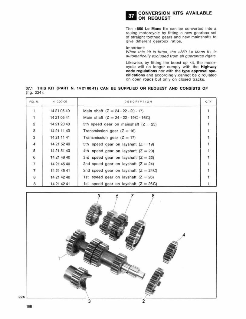
II!II!I CONVERSION KITS AVAILABLE ~ON REQUEST
The .. 850 Le Mans II .. can be converted into a racing motorcycle by filting a new gearbox sel of straight toothed gears and new mainshafts to give different gearbox ralios.
Important: When this kit is fitted, the .. 850 Le Mans II ,. is automatically excluded from a/l guarantee rights .
Likewise, by fitting the boost up kit , the moto rcycle will no longer comply with the Highway code regulations nor with the type approval specifications and accordingly cannot be circulated on open roads but on ly on closed tracks.
37.1 THIS KIT (PART N. 14210041) CAN BE SUPPLIED ON REQUEST AND CONSISTS OF (fig . 224),
FIG. N. N. coolee DESCRIPTION C.r<
1 14210540 Main shaft (Z ~ 24 - 22 - 20 - 17) 1
1 14210541 Main shaft (Z ~ 24-22- 19C-16C) 1
2 14212040 5th speed gear on mainshaft (Z ~ 25) 1
3 14211 140 Transmission gear (Z ~ 16) 1
3 14211141 Transmission gear (Z ~ 17) 1
4 14 215240 5th speed gear on layshaft (Z ~ 19) 1
5 142151 40 41h speed gear on lays haft (Z ~ 20) 1
6 14214840 3rd speed gear on lays haft (Z ~ 22) 1
7 1421 45 40 2nd speed gear on layshaft (Z = 24) 1
7 1421 4541 2nd speed gear on layshaft (Z = 24C) 1
8 14214240 151 speed gear on layshafl (Z ~ 26) 1
8 14214241 1st speed gear on layshaft (Z ~ 26C) 1
224 L-_________________ " __________________ ~----------------------J
168
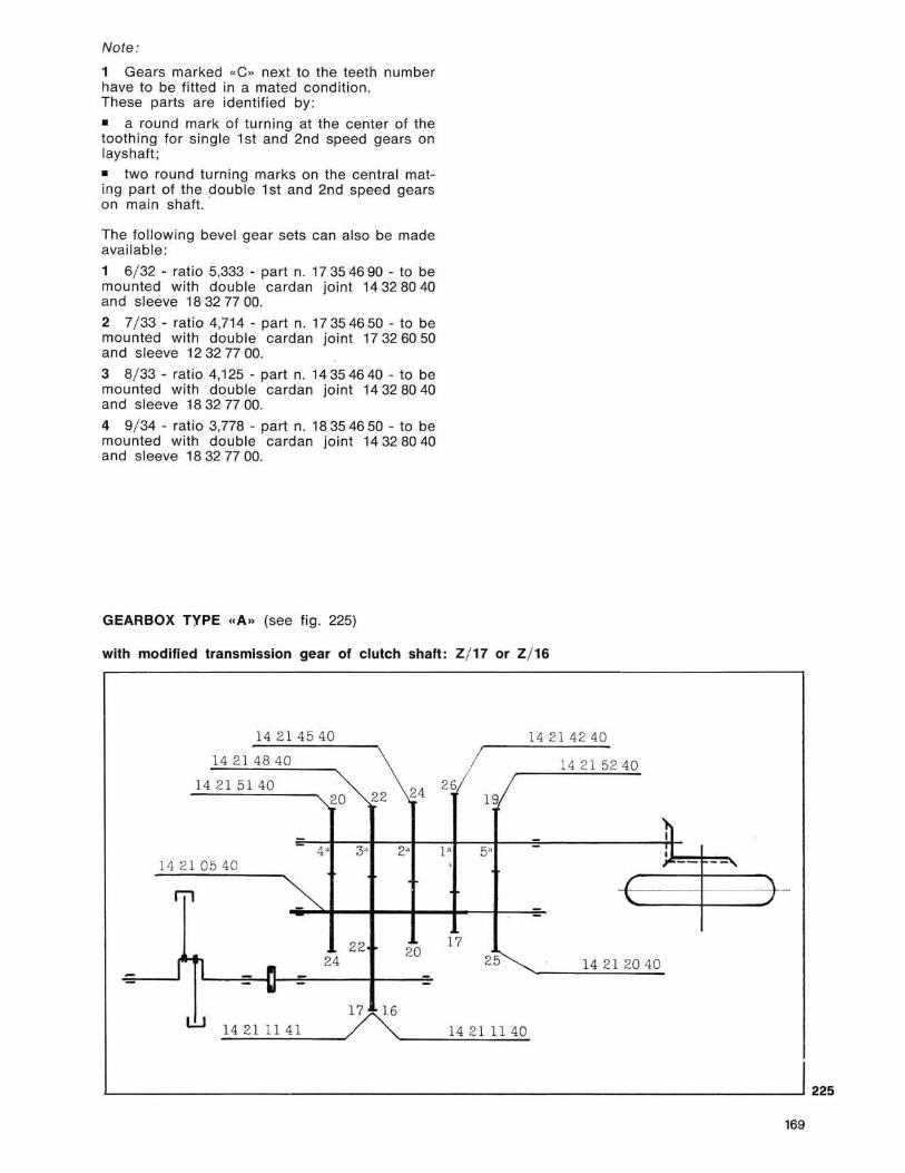
Note:
1 Gears marked " C .. next to the teeth number have to be f itted in a mated condition . These parts are identified by:
• a round mark of turning at the center of the loathing for single 1 sl and 2nd speed gears on Jayshaft ;
• two round turning marks on the central mating part of the double 1st and 2nd speed gears on main shaft. '
The following bevel gear sets can also be made available :
1 6/ 32 - ratio 5,333 - parI n. 17354690 - to be mounted with double cardan jOint 14328040 and sleeve 183277 00.
2 7/ 33 - ratio 4,714 - pari n. 17 35 46 50 - to be mounted with double cardan joint 17 32 60 50 and sleeve 123277 00.
3 8/ 33 - ratio 4,125 - part n. 14354640 - to be mounted with double cardan joint 14328040 and sleeve 183277 00.
4 9/ 34 - ratio 3,778 - part n. 18354650 - to be mounted with double ca rdan jOint 14328040 and sleeve 183277 00.
GEARBOX TYPE <f A » (see fig . 225)
with modified transmission gear of c lutch shaft : Z/ 17 or Z/ 16
1421 4540 14 2 14240
14 214840 14 2 152 40
14 215140 24 26 20 22 19
- -- 4" 3' 2' P 5" -14 2 10540 .
~ 171 --22 17
20 h ~
24 25 14 21 20 40 - -~ - -
17 16
"1~4~2~1~1~1_4~1~ __ J~~ ____ ~1~4~2~1~1~1~4""0
) I , - --,
L-______________________________________________________________ ~225
' 69
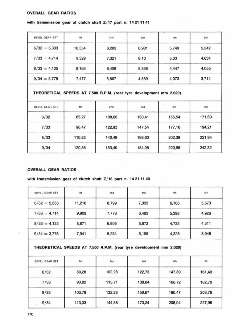
OVERALL GEAR RATIOS
with transmission gear of clutch shaft Z/ 17 part n. 14211141
BEVEl. GEAR SET '" ,", '" '" "" 6/ 32 = 5.333 10,554 8,282 6.901 5,749 5,242
7/ 33 = 4.714 9.329 7,321 6.10 5,03 4.634
8/ 33 = 4.125 8.163 6.406 5.338 4,447 4,055
9/34 = 3.778 7.477 5,867 4.889 4.073 3,71 4
THEORETICAL SPEEDS AT 7.500 R.P.M. (rear lyre development mm 2.020)
BEVEL GE"R SET '" ,", ,., '" '" 6/ 32 85.27 108.66 130,41 156.54 171 .69
7/ 33 96,47 122,93 147,54 177,16 194,21 --
8/ 33 110,25 140,49 168.60 202,38 221 ,94
9/ 34 120.36 153,40 184.08 220.96 242.32
·OVERALL GEAR RATIOS
with transmission gear of clutch shaft Z/ 16 part n. 14211140
BEVEl. Ge.-.R SET '" , .. ,., '" "" 6/ 32 = 5.333 11 ,210 8,799 7.333 6.106 5,573
7/ 33 = 4.714 9.909 7,778 6,482 5.398 4,926
8/ 33 = 4.125 8,671 6.806 5.672 4.725 4,31 1
9/ 34 = 3.778 7,941 6.234 5,195 4.326 3,948
THEORETICAL SPEEDS AT 7,500 R.P,M. (rear tyre development mm 2.020)
BEVEL GEAR SET '" ,", ,., '" "" 6/ 32 80.28 102,28 122.73 147,39 161,49
7/ 33 90.82 115,71 138.84 166.72 182,70
8/ 33 103,79 132,23 158,67 190,47 208.76
9/ 34 113.33 144.36 173,24 208.04 227.96
170
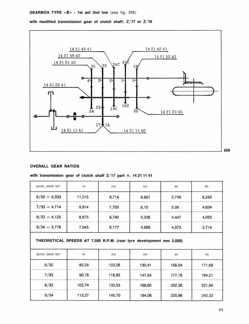
GEARBOX TYPE .. B .. - 1st ani 2nd low (see fig . 226)
with modified transmission gear of clutch shaft : Z/ 17 or Z/ 16
14214541 14214241
14214840 14215240
14 215140 24C 2 I" 1 20 22
I
4' 3' 2' I ' 5' - , 142105 4 1 - --
171 "" 22 ,9C 16C
• 24 25 14 21 2040 - - V - -17 16
I.!J 14211141 1421 1-140
226
OVERAll GEAR RATIOS
with transmission gear of clutch shaft Z/ 17 part n. 14211141
BEVEL GEAR SET '" "'" ,., '" "'
6/ 32 = 5,333 '1 .215 8,71 4 6,901 5.749 5.242
7/ 33 = 4.714 9,914 7,703 .6,10 5.08 4,634
8/ 33 = 4,125 8.675 6,740 5,338 4.447 4,055
9/ 34 = 3,778 7.945 6.177 4.889 4.073 3.71 4
THEORETICAL SPEEDS AT 7.500 R.P.M. (rear tyre development mm 2.020)
BEVEL GEAR SET '" "'" ,.,
'" "' 6/ 32 80,24 103.28 130,41 156.54 171.69
7/ 33 90,78 116.83 147.54 177,16 194,21
8/ 33 103.74 133,53 168,60 202,38 221 ,94
9/ 34 113.27 145.70 184.08 220,96 242.32
171
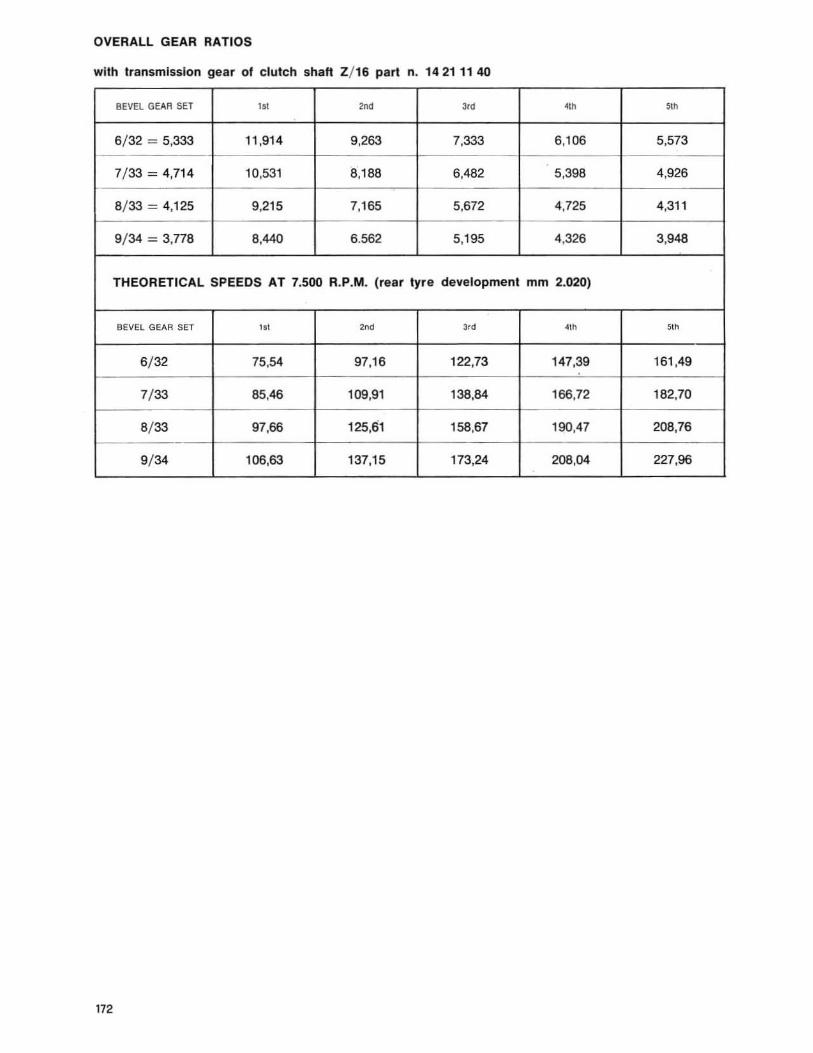
OVERAll GEAR RATIOS
with transmission gear of clutch shaH Z/ 16 part n. 14211140
BEVEL GEAR SET '" '''' 3,d "" .. 6/ 32 ~ 5,333 11,914 9,263 7,333 6,106 5,573
7/ 33 ~ 4,714 10,531 8,188 6,482 5 ,398 4,926
8/ 33 ~ 4,125 9,215 7,165 5,672 4,725 4,311
9/ 34 ~ 3,n8 8,440 6.562 5,195 4,326 3,948
THEORETICAL SPEEDS AT 7.500 R.P.M. (rear tyre development mm 2.020)
BeVEL GEAR SET '" '"' "d "" "" 6/ 32 75,54 97,16 122,73 147.39 161 ,49
7/ 33 85,46 109,91 138,84 166,72 182,70
8/ 33 97,66 125,61 158,67 190,47 208,76
9/ 34 106,63 137,15 173,24 208,04 227,96
172
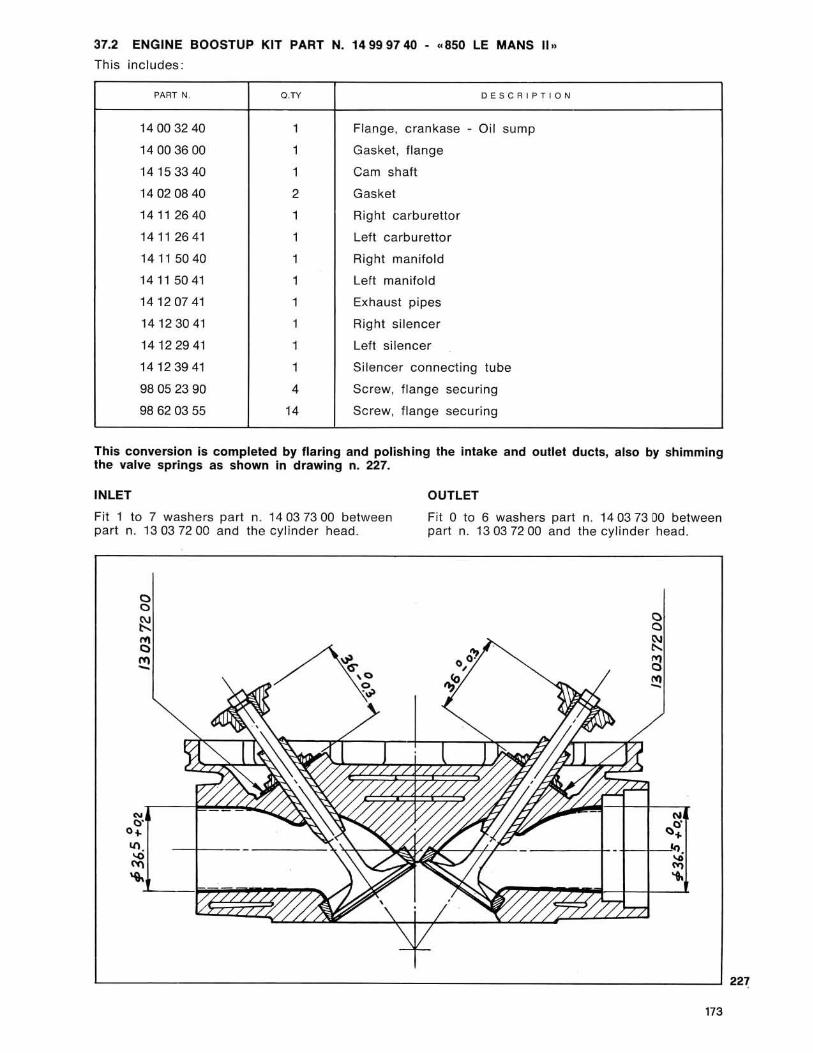
37.2 ENGINE BOOSTUP KIT PART N. 14999740 • «850 LE MANS II »
This includes:
PART N. Q." DESCRIP T IO N
14003240 1 Flange, crankase - Oil sump
14003600 1 Gasket, flange
14153340 1 Cam shaft
14020840 2 Gasket
14112640 1 Right carburettor
141 12641 1 Left carbu retto r
14115040 1 Right manifold
14115041 1 Left manifold
14120741 1 Exhaust pipes
14123041 1 Right silencer
14122941 1 Left silencer
14123941 1 Silencer connecting tube
98052390 • Screw, flange securing
98620355 ,. Screw, flange securing
This conversion is completed by flaring and polishing the intake and outlet ducts, also by shimming the valve springs as shown in drawing n. 227.
INLET
Fit 1 to 7 washers pari n. 14037300 between part n. 13037200 and the cylinder head.
N o· o. "'. ~
OUTLET
Fit 0 to 6 washers part n. 140373 00 between pari n. 130372 00 and the cyl inder head.
0" 0,
.,'"
N o· "'.
+-+-". ~ ...
~L-~~~~..J..--.,L-~ljLLL-L-LkLJ
173
22~


SEIMM MOTO GUZZI S. p. A. Mend.llo del lerio