Embed Size (px)
Citation preview
��������� ����������
��������������� ��������������
���������������������
�� �� �����������
�������������� �������
2
INDEX
Page 1. GENERAL INFORMATION .......................................................................... 3
2. SYSTEM COMPONENTS ............................................................................. 4
2.1 Construction ............................................................................................................. 4
2.2 Control Cabinet ......................................................................................................... 6
2.3 Electrical and Electronical Components ........................................................................ 6
2.4 Pneumatic Components .............................................................................................. 8
3. OPERATION INSTRUCTIONS .................................................................... 9
4. MAINTENANCE .......................................................................................... 11
5. PRACTICAL TROUBLESHOOTING PROCEDURES ...................................... 12
6. CE DECLERATION ...................................................................................... 14
7. ISO 14OO1 : 2004 CERTIFICATE .............................................................. 15
8. ISO 9001 : 2008 CERTIFICATE ................................................................. 16
�������������� �������
3
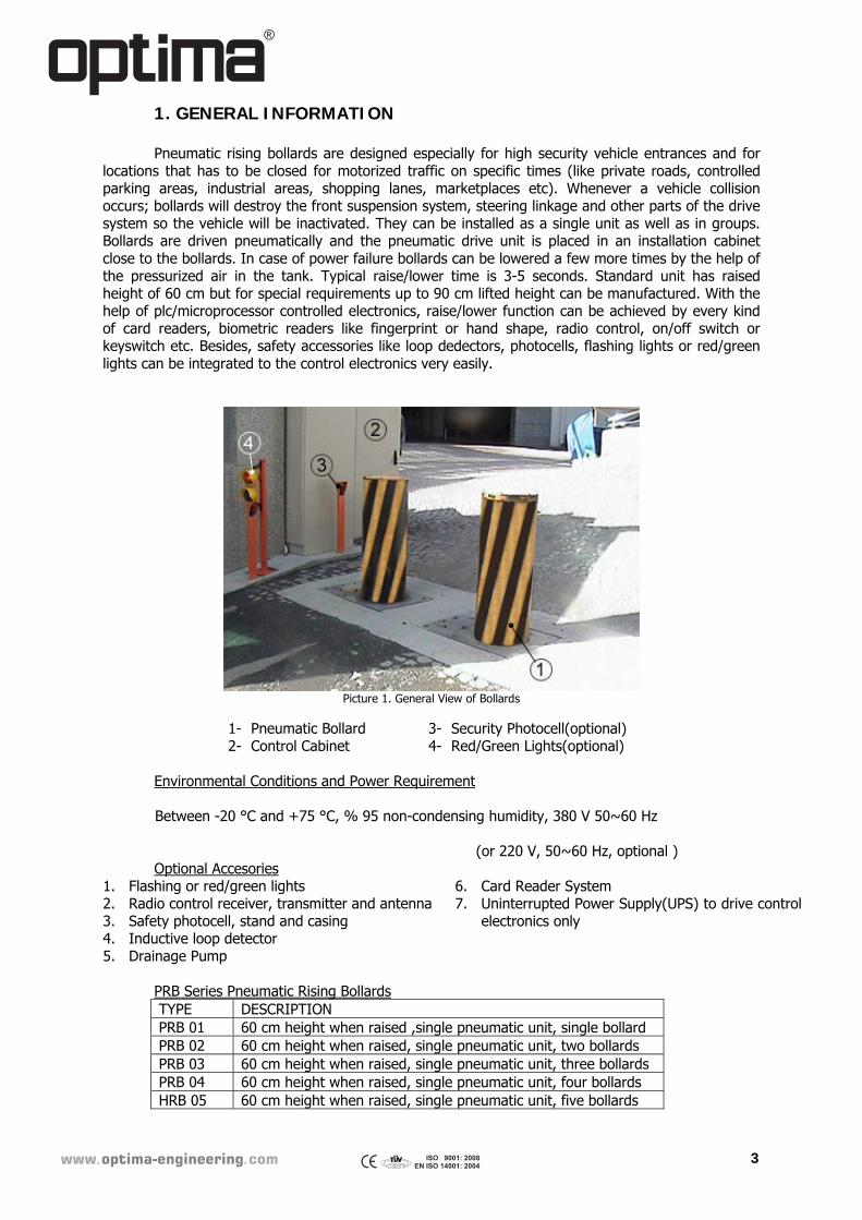
1. GENERAL INFORMATION Pneumatic rising bollards are designed especially for high security vehicle entrances and for locations that has to be closed for motorized traffic on specific times (like private roads, controlled parking areas, industrial areas, shopping lanes, marketplaces etc). Whenever a vehicle collision occurs; bollards will destroy the front suspension system, steering linkage and other parts of the drive system so the vehicle will be inactivated. They can be installed as a single unit as well as in groups. Bollards are driven pneumatically and the pneumatic drive unit is placed in an installation cabinet close to the bollards. In case of power failure bollards can be lowered a few more times by the help of the pressurized air in the tank. Typical raise/lower time is 3-5 seconds. Standard unit has raised height of 60 cm but for special requirements up to 90 cm lifted height can be manufactured. With the help of plc/microprocessor controlled electronics, raise/lower function can be achieved by every kind of card readers, biometric readers like fingerprint or hand shape, radio control, on/off switch or keyswitch etc. Besides, safety accessories like loop dedectors, photocells, flashing lights or red/green lights can be integrated to the control electronics very easily.
Picture 1. General View of Bollards
1- Pneumatic Bollard 2- Control Cabinet
3- Security Photocell(optional) 4- Red/Green Lights(optional)
Environmental Conditions and Power Requirement
Between -20 °C and +75 °C, % 95 non-condensing humidity, 380 V 50~60 Hz (or 220 V, 50~60 Hz, optional )
Optional Accesories 1. Flashing or red/green lights 2. Radio control receiver, transmitter and antenna 3. Safety photocell, stand and casing 4. Inductive loop detector 5. Drainage Pump
6. Card Reader System 7. Uninterrupted Power Supply(UPS) to drive control
electronics only
PRB Series Pneumatic Rising Bollards TYPE DESCRIPTION PRB 01 60 cm height when raised ,single pneumatic unit, single bollard PRB 02 60 cm height when raised, single pneumatic unit, two bollards PRB 03 60 cm height when raised, single pneumatic unit, three bollards PRB 04 60 cm height when raised, single pneumatic unit, four bollards HRB 05 60 cm height when raised, single pneumatic unit, five bollards
�������������� �������
4
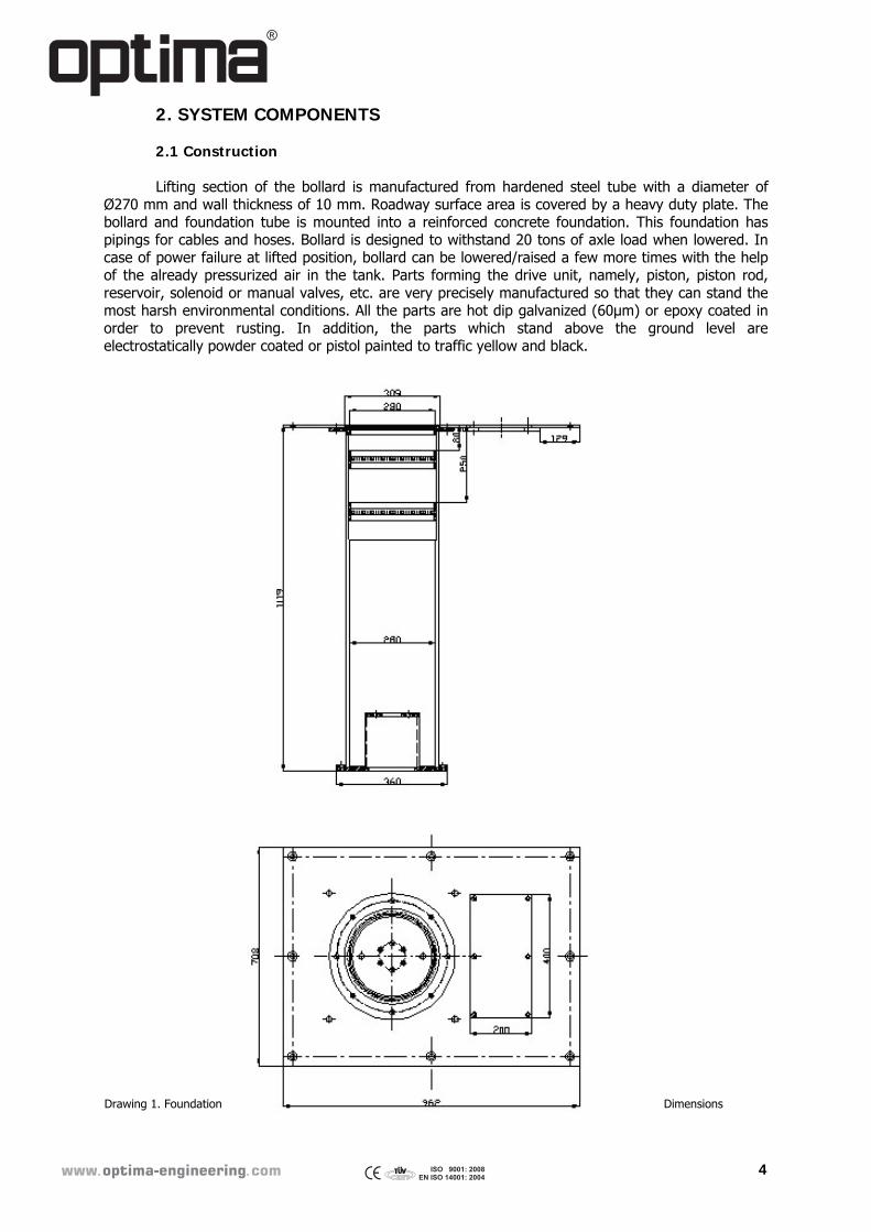
2. SYSTEM COMPONENTS 2.1 Construction Lifting section of the bollard is manufactured from hardened steel tube with a diameter of Ø270 mm and wall thickness of 10 mm. Roadway surface area is covered by a heavy duty plate. The bollard and foundation tube is mounted into a reinforced concrete foundation. This foundation has pipings for cables and hoses. Bollard is designed to withstand 20 tons of axle load when lowered. In case of power failure at lifted position, bollard can be lowered/raised a few more times with the help of the already pressurized air in the tank. Parts forming the drive unit, namely, piston, piston rod, reservoir, solenoid or manual valves, etc. are very precisely manufactured so that they can stand the most harsh environmental conditions. All the parts are hot dip galvanized (60µm) or epoxy coated in order to prevent rusting. In addition, the parts which stand above the ground level are electrostatically powder coated or pistol painted to traffic yellow and black.
Drawing 1. Foundation Dimensions
�������������� �������
5
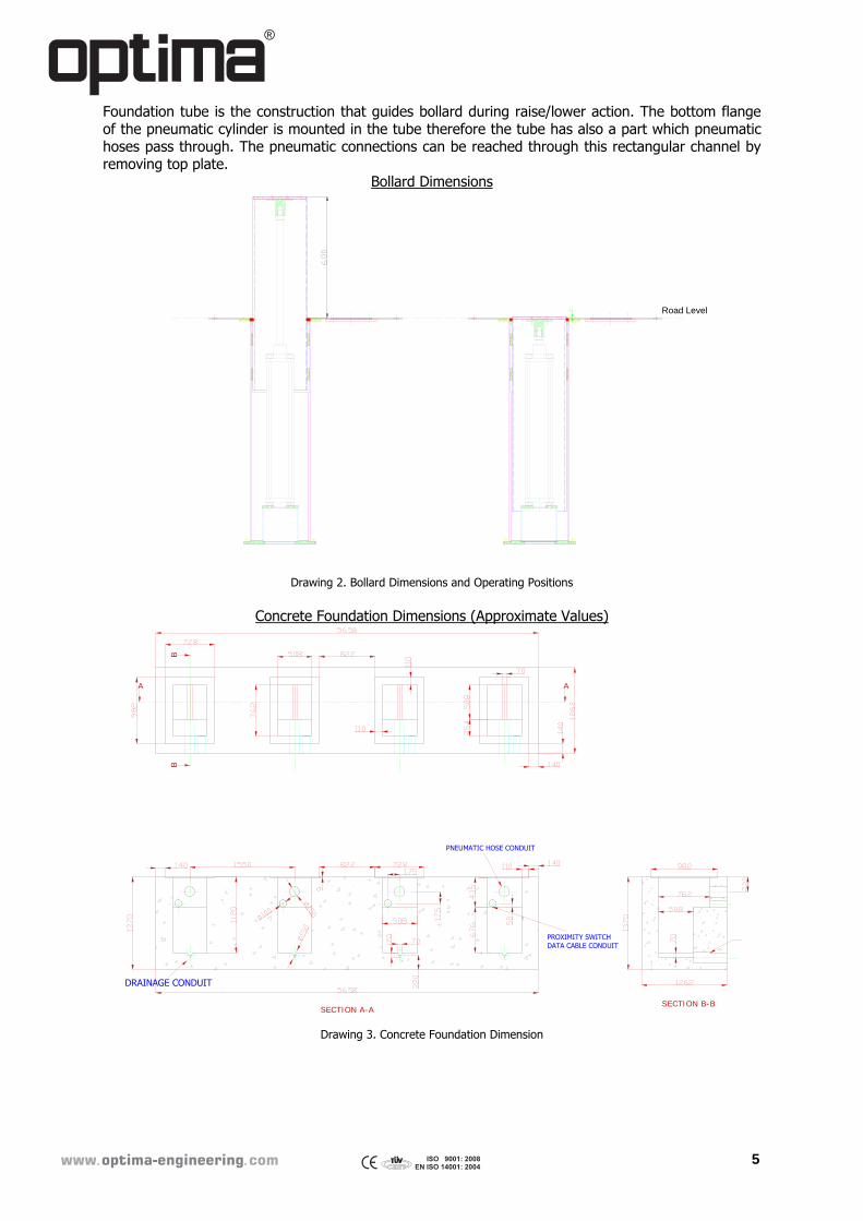
Foundation tube is the construction that guides bollard during raise/lower action. The bottom flange of the pneumatic cylinder is mounted in the tube therefore the tube has also a part which pneumatic hoses pass through. The pneumatic connections can be reached through this rectangular channel by removing top plate.
Bollard Dimensions
Drawing 2. Bollard Dimensions and Operating Positions
Concrete Foundation Dimensions (Approximate Values)
Drawing 3. Concrete Foundation Dimension
Road Level
SECTION A-ASECTION B-B
A A
BB
DRAINAGE CONDUIT
PNEUMATIC HOSE CONDUIT
PROXIMITY SWITCHDATA CABLE CONDUIT
�������������� �������
6
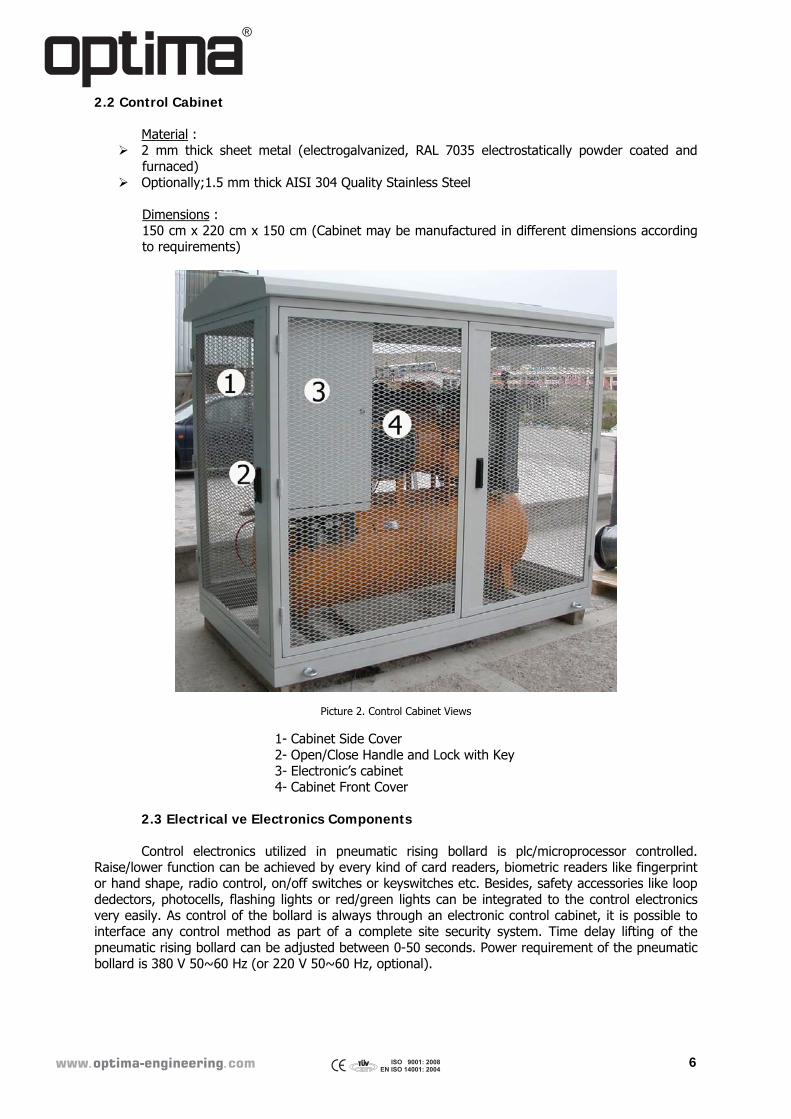
2.2 Control Cabinet
Material : 2 mm thick sheet metal (electrogalvanized, RAL 7035 electrostatically powder coated and
furnaced) Optionally;1.5 mm thick AISI 304 Quality Stainless Steel
Dimensions : 150 cm x 220 cm x 150 cm (Cabinet may be manufactured in different dimensions according to requirements)
Picture 2. Control Cabinet Views
1- Cabinet Side Cover 2- Open/Close Handle and Lock with Key 3- Electronic’s cabinet 4- Cabinet Front Cover
2.3 Electrical ve Electronics Components Control electronics utilized in pneumatic rising bollard is plc/microprocessor controlled. Raise/lower function can be achieved by every kind of card readers, biometric readers like fingerprint or hand shape, radio control, on/off switches or keyswitches etc. Besides, safety accessories like loop dedectors, photocells, flashing lights or red/green lights can be integrated to the control electronics very easily. As control of the bollard is always through an electronic control cabinet, it is possible to interface any control method as part of a complete site security system. Time delay lifting of the pneumatic rising bollard can be adjusted between 0-50 seconds. Power requirement of the pneumatic bollard is 380 V 50~60 Hz (or 220 V 50~60 Hz, optional).
�������������� �������
7
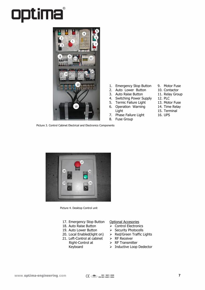
Picture 3. Control Cabinet Electrical and Electronics Components
1. Emergency Stop Button 2. Auto Lower Button 3. Auto Raise Button 4. Switching Power Supply 5. Termic Failure Light 6. Operation Warning
Light 7. Phase Failure Light 8. Fuse Group
9. Motor Fuse 10. Contactor 11. Relay Group 12. PLC 13. Motor Fuse 14. Time Relay 15. Terminal 16. UPS
Picture 4. Desktop Control unit
17. Emergency Stop Button 18. Auto Raise Button 19. Auto Lower Button 20. Local Enabled(light on) 21. Left-Control at cabinet Right-Control at
Keyboard
Optional Accesories Control Electronics Security Photocells Red/Green Traffic Lights RF Receiver RF Transmitter Inductive Loop Dedector
�������������� �������
8
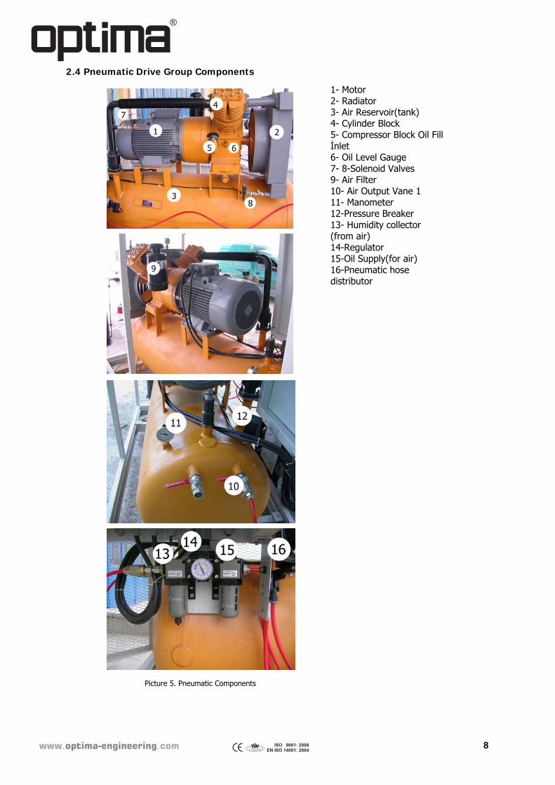
2.4 Pneumatic Drive Group Components
1- Motor 2- Radiator 3- Air Reservoir(tank) 4- Cylinder Block 5- Compressor Block Oil Fill İnlet 6- Oil Level Gauge 7- 8-Solenoid Valves 9- Air Filter 10- Air Output Vane 1 11- Manometer 12-Pressure Breaker 13- Humidity collector (from air) 14-Regulator 15-Oil Supply(for air) 16-Pneumatic hose distributor
Picture 5. Pneumatic Components
�������������� �������
9
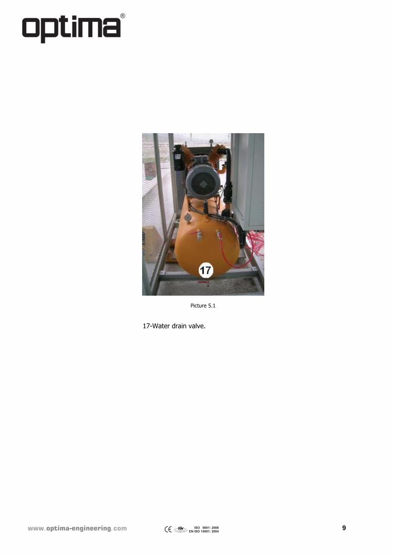
Picture 5.1
17-Water drain valve.
�������������� �������
10
3. OPERATION INSTRUCTIONS
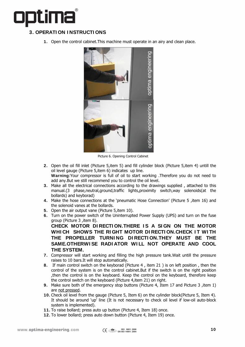
1. Open the control cabinet.This machine must operate in an airy and clean place.
Picture 6. Opening Control Cabinet
2. Open the oil fill inlet (Picture 5,item 5) and fill cylinder block (Picture 5,item 4) untill the oil level gauge (Picture 5,item 6) indicates up line. Warning:Your compressor is full of oil to start working .Therefore you do not need to add any.But we still recommend you to control the oil level.
3. Make all the electrical connections according to the drawings supplied , attached to this manual.(3 phase,neutral,ground,traffic lights,proximity switch,way solenoids(at the bollards) and keyborad)
4. Make the hose connections at the ‘pneumatic Hose Connection’ (Picture 5 ,item 16) and the solenoid vanes at the bollards.
5. Open the air output vane (Picture 5,item 10). 6. Turn on the power switch of the Uninterrupted Power Supply (UPS) and turn on the fuse
group (Picture 3 ,item 8). CHECK MOTOR DIRECTION.THERE IS A SIGN ON THE MOTOR WHICH SHOWS THE RIGHT MOTOR DIRECTION.CHECK IT WITH THE PROPELLER TURNING DIRECTION.THEY MUST BE THE SAME.OTHERWISE RADIATOR WILL NOT OPERATE AND COOL THE SYSTEM.
7. Compressor will start working and filling the high pressure tank.Wait untill the pressure raises to 10 bars.It will stop automatically.
8. If main control switch on the keyborad (Picture 4 , item 21 ) is on left position , then the control of the system is on the control cabinet.But if the switch is on the right position ,then the control is on the keyboard. Keep the control on the keyboard, therefore keep the control switch on the keyboard (Picture 4,item 21) on right.
9. Make sure both of the emergency stop buttons (Picture 4, Item 17 and Picture 3 ,item 1) are not pressed.
10. Check oil level from the gauge (Picture 5, Item 6) on the cylinder block(Picture 5, Item 4). It should be around ‘up’ line (It is not necessary to check oil level if low-oil auto-block system is implemented).
11. To raise bollard; press auto up button (Picture 4, Item 18) once. 12. To lower bollard; press auto down button (Picture 4, Item 19) once.
�������������� �������
11
13. Humidity collector has a reservoir (Picture 5, Item 13) underneath . It collects water to this reservoir. This reservuar has the vane at the bottom. This vane is used to drain the collected water. Therefore , user must follow the fullness of this reservoir and drain it when necessary.The frequency of this process depends on the humidty of the environment and working hours of the compressor.
14. Oil supply gives oil to air(Picture 5, Item 15) which are going to the solenoid vanes. Put oil to its reservoir when necessary.The oil there is not an ordinary oil,it is called ‘oil to condition air for pneumatic pistons’.
15. Air filter must be cleaned once a week (Picture 5, Item 9). Please follow the directions above for both entrance and exit bollards.
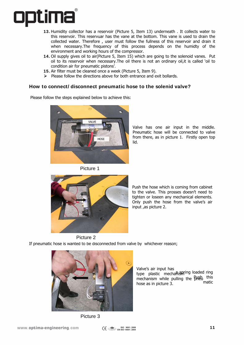
How to connect/disconnect pneumatic hose to the solenid valve? Please follow the steps explained below to achieve this:
Valve has one air input in the middle. Pneumatic hose will be connected to valve from there, as in picture 1. Firstly open top lid.
Push the hose which is coming from cabinet
to the valve. This prosses doesn’t need to tighten or loseen any mechanical elements. Only push the hose from the valve’s air input ,as picture 2.
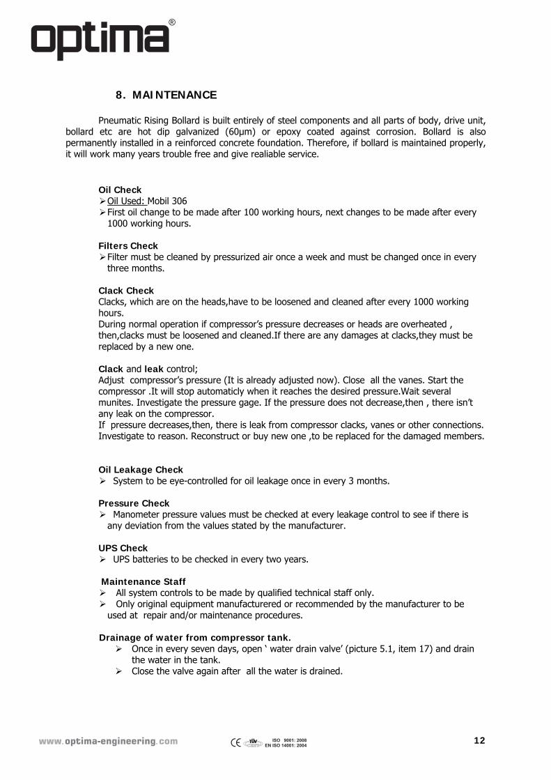
If pneumatic hose is wanted to be disconnected from valve by whichever reason;
Valve’s air input has
a spring loaded ring type plastic mechanism . Push this mechanism while pulling the pneu
matic hose as in picture 3.
Picture 1
Picture 2
Picture 3
�������������� �������
12
8. MAINTENANCE Pneumatic Rising Bollard is built entirely of steel components and all parts of body, drive unit,
bollard etc are hot dip galvanized (60µm) or epoxy coated against corrosion. Bollard is also permanently installed in a reinforced concrete foundation. Therefore, if bollard is maintained properly, it will work many years trouble free and give realiable service.
Oil Check Oil Used: Mobil 306 First oil change to be made after 100 working hours, next changes to be made after every
1000 working hours. Filters Check Filter must be cleaned by pressurized air once a week and must be changed once in every
three months. Clack Check Clacks, which are on the heads,have to be loosened and cleaned after every 1000 working hours. During normal operation if compressor’s pressure decreases or heads are overheated , then,clacks must be loosened and cleaned.If there are any damages at clacks,they must be replaced by a new one. Clack and leak control; Adjust compressor’s pressure (It is already adjusted now). Close all the vanes. Start the compressor .It will stop automaticly when it reaches the desired pressure.Wait several munites. Investigate the pressure gage. If the pressure does not decrease,then , there isn’t any leak on the compressor. If pressure decreases,then, there is leak from compressor clacks, vanes or other connections. Investigate to reason. Reconstruct or buy new one ,to be replaced for the damaged members.
Oil Leakage Check System to be eye-controlled for oil leakage once in every 3 months. Pressure Check Manometer pressure values must be checked at every leakage control to see if there is
any deviation from the values stated by the manufacturer. UPS Check UPS batteries to be checked in every two years.
Maintenance Staff All system controls to be made by qualified technical staff only. Only original equipment manufacturered or recommended by the manufacturer to be
used at repair and/or maintenance procedures. Drainage of water from compressor tank. Once in every seven days, open ‘ water drain valve’ (picture 5.1, item 17) and drain
the water in the tank. Close the valve again after all the water is drained.
�������������� �������
13
9. PRACTICAL TROUBLESHOOTING PROCEDURES
If there is no movement observed after pressing auto raise/lower buttons;
- Make sure emergency stop buttons (Picture 4, Item 17 and Picture 3, Item 1) are not pressed.
- Make sure all fuses (Picture 3, Item 8) are in upwards position. - Make sure keyboard control switch is on the proper position.
If there are unexpected behaviours in system, quickly stop the system by pressing emergency
stop button (Picture 4, Item 17). In case of power failure,
- Bollards will continue to work for a few more times as there is already pressurized air in
the reservoir .
Please follow the directions above for both entrance and exit bollards. If the system is not still running after all these controls please contact with the manufacturer.
Diagram for Finding Failure for Compressor
Failure Probable Reason What must be done?
1.If air supply decreases There is leakage at the first level suction clacks.
Loosen the clacks, clean them or change with a new one.
There is adherance at the discharge piston.
Dismount the piston then clean and lubricate it.
Dirty air is sucked. Clean the filter. 2.If intercooler pressure is too
low There is leakage at the first
level suction clacks. Dismount the clacks, clean
them or change with new one. 3. If intercooler pressure is too
high There is blockage eitherat the
discharge piston or release valve.
Dismount the piston then clean and oil lubricte it.
There is leakage at the second grade absorb clacks.
Loosen the clacks, clean them or change with new one.
4. If there is excessive heat at the compressor.
Intercooler and cooling fin is dirty.
Clean the compressor by pressurized air.
Calck is to be damaged. Oil lubriction is not enough.
Renew to old one, fill oil until line is on the dip rode.
5. If oil consumption is too high Oil level is too high. Empty oil untill designated oil level.
Piston ring had been abrasioned and/or piston and cylinder had
been aged.
Renew the old elements.
6. If there is noise and vibration at the compressor.
Piston is hitting cylinder’s head. Put a new gasket between the cylinder and cylinder’s head.
Piston is hitting the calck. Inspect to clack’s gasket. Balance wheel or air blower had
been loosen. Tighten bolts and nuts.
7. If there is evacuation at the first level safety release valve.
There is leakage at the second level suction clacks.
Dismount the clacks, clean them or change with a new
one. Safety release valve had been
loosened. Dismount the valve. Clean the valve and then assemble it to
the initial place.
�������������� �������
14
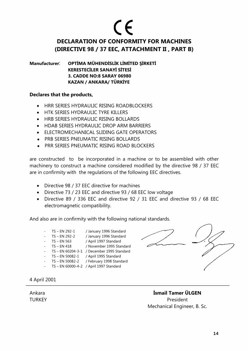
DECLARATION OF CONFORMITY FOR MACHINES (DIRECTIVE 98 / 37 EEC, ATTACHMENT II , PART B)
Manufacturer: OPTİMA MÜHENDİSLİK LİMİTED ŞİRKETİ KERESTECİLER SANAYİ SİTESİ 3. CADDE NO:8 SARAY 06980 KAZAN / ANKARA/ TÜRKİYE Declares that the products,
HRR SERIES HYDRAULIC RISING ROADBLOCKERS HTK SERIES HYDRAULIC TYRE KILLERS HRB SERIES HYDRAULIC RISING BOLLARDS HDAB SERIES HYDRAULIC DROP ARM BARRIERS ELECTROMECHANICAL SLIDING GATE OPERATORS
PRB SERIES PNEUMATIC RISING BOLLARDS ● PRR SERIES PNEUMATIC RISING ROAD BLOCKERS ● are constructed to be incorporated in a machine or to be assembled with other machinery to construct a machine considered modified by the directive 98 / 37 EEC are in confirmity with the regulations of the following EEC directives.
Directive 98 / 37 EEC directive for machines Directive 73 / 23 EEC and directive 93 / 68 EEC low voltage Directive 89 / 336 EEC and directive 92 / 31 EEC and directive 93 / 68 EEC
electromagnetic compatibility. And also are in confirmity with the following national standards.
- TS – EN 292-1 / January 1996 Standard - TS – EN 292-2 / January 1996 Standard - TS – EN 563 / April 1997 Standard - TS – EN 418 / November 1995 Standard - TS – EN 60204-3-1 / December 1995 Standard - TS – EN 50082-1 / April 1995 Standard - TS – EN 50082-2 / February 1998 Standard - TS – EN 60000-4-2 / April 1997 Standard
4 April 2001 Ankara İsmail Tamer ÜLGEN TURKEY President Mechanical Engineer, B. Sc.
15
16