Embed Size (px)
Citation preview
Risk-Based Safety and Mission Assurance: Approach and Experiences in Practice
Jesse Leitner, Bhanu Sood, Eric Isaac, Jack Shue, Nancy Lindsey, Jeannette Plante
NASA GSFC
Greenbelt, MD 20771
Contact author:
Jesse Leitner
NASA GSFC, Code 300
Greenbelt, MD 20771
301-286-2630
Risk-Based Safety and Mission Assurance: Approach and Experiences in Practice
Jesse Leitner, Bhanu Sood, Eric Isaac, Jack Shue, Nancy Lindsey, Jeannette Plante
NASA GSFC
Greenbelt, MD 20771
Abstract
In 2014, in response to a large volume of feedback from industry, the science community, and
internal to Goddard Space Flight Center (GSFC), GSFC’s Safety and Mission Assurance (SMA)
Directorate began a transition to a risk-based implementation of SMA, departing from its
longstanding practice of being primarily driven by a mostly-static set of Mission Assurance
Requirements. The transition started out with a pilot project involving risk-based acceptance of
bare printed circuit boards that was enormously successful, continued through a complete
organizational transformation in 2015, and culminated with the baselining of formal Risk-Based
SMA policy in 2016. This paper highlights five major examples of successful implementation of
Risk-Based SMA that have demonstrated not only substantial savings in project resources, but
also the ability to achieve the lowest level of risk in developing and operating inherently risky
systems.
Key words: quality, reliability, risk-based safety and mission assurance, risk-informed decision
making, risk management
This paper is a declared work of the U.S. Government and is not subject to copyright laws in the United
States of America

1.0 Introduction
In 2016, NASA Goddard Space Flight Center (GSFC) formally established a policy for risk-
based safety and mission assurance (SMA) through the publication of Goddard Procedural
Requirement (GPR) 8705.4, Risk Classification Guidelines and Risk-Based SMA Practices for
GSFC Payloads and Systems (NASA GSFC, June 2016). This document serves to provide
guidance and repeatability to projects seeking to align SMA requirements with the mission’s risk
tolerance profile, greatly reducing the risk that the process of assigning requirements has missed
a critical requirement or is imposing one that will excessively drive up programmatic risk. The
guidance is expected to streamline internal review and approval and to provide a repository for
lessons learned. This set in motion new approaches not only for selecting up-front requirements,
but also for responding to various scenarios encountered in system development. In 2014, while
GPR 8705.4 was being developed, GSFC’s SMA organization began pilot studies for
implementing the approach. This paper presents the risk-based SMA framework that is
embodied in GSFC’s command media (e.g., requirements directives and policy documents,
standards, and a variety of other configuration-managed forms of documentation) and
characterizes the benefits achieved for a small selection of key results since the policy has been
instituted through the 2014 pilot study and formal implementation that started in June of 2016. It
presents several case studies showing how these risk-based SMA principles were applied, along
with their observed outcomes. In this paper, as in high-level directives and standards at GSFC
that embody the risk-based SMA framework, direction will be in the form of guidance (i.e.,
“should” statements), while in most cases, it will be up to individual projects and stakeholder
expectations to establish requirements (i.e., “shall” statements). However, the risk-based SMA
philosophy will emphasize that very few requirements are sacred and that risk should always be
considered, especially in cases where there is a strong pushback against a requirement by the
developer.
1.1 Goddard Space Flight Center Overview
NASA’s Goddard Space Flight Center, NASA’s first and oldest space center, houses the largest
organization in the United States of scientists, engineers, and technologists who build spacecraft,
instruments, and new technology to study Earth, the sun, our solar system, and the universe.
GSFC has about 25 current spacecraft and space instrument projects in development at the
moment, some in-house, some contracted out-of-house, and some a mix of both. These projects
enable space missions to collect scientific information, prove out technologies, provide a national
service such as weather assessment and prediction, or support other national or international
priorities. These include the James Webb Space Telescope, the GOES-R series of weather
satellites, the Joint Polar Satellite System (JPSS) series of weather satellites, and the ICESat-2
spacecraft with the ATLAS laser instrument to name a few. GSFC is also operating dozens of
current spacecraft, such as the Hubble Space Telescope, the Magnetospheric Multi Scale mission
formation, and much of the Earth-observing system (EOS) constellation, for example. GSFC has
a very long history of mission success, with most missions surpassing their design lifetimes by at
least a factor of two, and frequently a factor of five, 10, or greater. With GSFC’s resounding
success in developing and operating space missions also comes a fear of departing from
longstanding practices. Any challenge to longstanding successful practices, whether in science,
engineering, or safety and mission assurance, prompts a concern that failure may be around the
corner, with a potential to taint GSFC’s reputation. This fear introduced challenges in

transitioning from an approach of strict compliance to longstanding requirements to one of risk-
based SMA.
2.0 Risk-Based SMA Overview
Risk-based SMA is a guiding principle for achieving safe and successful missions with limited
resources. It focuses on mitigating specific risks using engineering judgment that are applicable
to a project versus simply enforcing a set of requirements because they have always worked in
the past. This does not imply that the focus of all SMA activities is driven by known risks, but
rather the activities and requirements are prioritized based on the known risks and the risk
posture of the project, and a continuous balancing of risk across the project is the objective (see
section 3.3). Ultimately, risk-based SMA is all about looking at the interconnected and
competing sides of project risks as opposed to treating risks as isolated concerns where
individual mitigation actions cannot drive unintended consequences elsewhere. To be most
effective at implementing risk-based SMA, it is important to consider risk in a very structured
and rigorous way, where a risk, based on a concern that an undesired event will occur, will
include a clear context as well as a likelihood and a consequence. Risks at GSFC come in three
categories: technical, programmatic, and safety. A technical risk is a potential problem that
involves the possibility of impact to Flight / Ground segments during operations (i.e., "end
products" performing their desired functions in their operational environments).” A
programmatic risk is a potential problem that involves the possibility of impact to development
activities and / or the ability to deliver the required product within the allocated budget, schedule,
and resources. A safety risk is a potential problem that involves the possibility of personnel
injury or death and/or damage to facilities or other property outside the ownership of a project or
program. It should be noted that typical development and risk mitigation activities within SMA
for space system development involve the use of resources and the encumbrance of
programmatic risk in order to make technical risk as low as possible. (Thorough understanding
of this trade is essential for effective implementation of risk-based SMA.) It is common practice
to use barriers and controls to simply eliminate safety risks or to make their likelihoods
extremely remote in the development of unmanned space systems.
The key elements of risk-based SMA are:
a. Risk-informed framework – architecting and prioritizing SMA practices toward the
highest-risk areas and employing proactive functions to mitigate common risk drivers
early in a project (for example, additional safety personnel applied to areas prone to
mishaps or extra quality personnel applied to development efforts that are highly
sensitive to workmanship errors).
b. Risk-informed requirements generation – applying more stringent requirements in
areas that are more critical or sensitive to forces outside of the project’s control and
employing guidance instead of strict requirements in areas where (1) there are many good
solutions, (2) team capability is high for technical decision-making, and (3) supplier
quality is high and stable.
c. Risk-informed decisions – decisions are made after considering the direct and collateral
risks and benefits of all of the mitigation options (e.g., repair vs. use-as-is, make vs. buy).
d. Risk-informed review and audit – review and audit will expose adherence to and many
violations of requirements, standard practices, best practices and lessons learned (within
GSFC and at external vendors) – the key is to use an assessment of risk that is relevant to
the mission conditions and objectives rather than a generic commitment to compliance to
determine the best path forward.
Risk-based SMA has the following attributes:
a. Upfront assessment of reliability and risk in order to prioritize how resources and
requirements will be applied
b. Early discussions with the system developers about their approach to ensuring mission
success and responsiveness to feedback and treatment of a departure from the developer’s
standard approach as a risk
c. Hybrid requirements that allow greater risk where the design has greater fault tolerance
and impose greater controls where fault tolerance is critical (e.g., using aggressively-
screened parts for critical items and commercially-screened parts where the design is
fault-tolerant)
d. Judicious application of requirements based on learning from previous projects, the
results from the reliability/risk assessment, and the operating environment (e.g., lessons
learned – multiple sources, cross-cutting risk assessments, etc.)
e. Characterization of risks to safety or mission success from nonconforming items to
determine suitability for use – the project determines whether to accept, not accept, or
mitigate risks based on consideration of all risks in the system
f. Characterization and mitigation of risks associated with particular designs, architectures,
or requirements sets.
g. Continuous review of requirements for suitability based on current processes,
technologies, and recent experiences.
h. Consideration of the risk of implementing a requirement vs. the risk of not implementing
the requirement.
i. Holistic, risk-based determination of the acceptability of items built to different standards
based on the understanding of the practices combined with prior experiences, rather than
seeking to address or close individual requirements gaps (e.g., per an inherited items
process (NASA GSFC, March 2016)).
3.0 Risk Assessment and Documentation
Guidelines for performing rigorous risk assessments for space systems are provided in GSFC-
HDBK-8005 – Guideline for Performing Risk Assessments (NASA GSFC, 2017). This
handbook provides foundational principles for ensuring that risks are compared at the same level
using a balanced approach.
This Section describes how GSFC characterizes the risk of nonconforming and out-of-family
items. When developers ascertain that a nonconforming item is acceptable for use in a particular
application, the developing organization should use reasonable means to eliminate or mitigate
the effects of the nonconformance. The developer should determine the risk of using the item as
is or establish an appropriate body (such as a material review board, parts control board, or
failure review board) to assess the risk. Achieving conformance after the fact is not necessarily
the priority.
The subject matter expert, or, at GSFC, the Commodity Risk Assessment Engineer (CRAE),
produces a risk statement to provide to the pertinent SMA Lead (e.g. the mission assurance
manager or chief safety and mission assurance officer). The CRAE will ultimately present risk
statements and supporting rationale to a project risk management board for disposition. Each
CRAE is assigned one or more key commodity areas (such as bare printed circuit boards,
standard spacecraft components, electronic packaging, electronic parts, or electromechanical
devices) for which they are continuously accumulating knowledge through lessons learned and
research. The SMA Lead works with the project to determine the acceptability of the risk and/or
risk mitigation options that the CRAE has characterized and provided to them.
3.1 Risk-based handling of deviations from requirements and nonconforming items
NASA’s supply chain consists of a wide variety of suppliers, some of whom have thrived over
decades through NASA contracts or subcontracts and others who may have no prior involvement
in aerospace at all. As a result, a project can establish a requirements baseline and levy that
baseline on a prime contractor and their subcontractors and encounter throughout the project
lifecycle suppliers who declare in advance that they cannot or will not be able to comply with
one or more of those baseline requirements. This may also apply to the prime contractor.
Waivers or similar records are used to capture these requests for requirements relief, and they
should be vetted by a CRAE or appropriate commodity expert. These requests are then captured
in a supplier risk management database as well as a lesson learned. Examples include:
a. Use of alternate and/or equivalent standards. The most typical examples are those used
for printed circuit boards (PCBs), soldering, conformal coating and staking, and cable
and wire harness manufacturing.
b. Use of a different electrical, electronic, and electromechanical (EEE) part quality and
reliability grading system such as /883 vs. Class B.
c. Materials of a lower grade than minimum specifications
d. Items built to an unqualified or nonstandard process
Late discovery of these conditions, where requirements relief was not previously negotiated, will
appear as a nonconformance.
After the supplier and the project agree to the requirements that will be applied, all failures to
meet a requirement are documented in the project’s nonconformance reporting system.
The formality of such documentation should be commensurate with the mission risk posture.
Nonconformances include:
a. Bare printed circuit boards or structural integrity coupons thereof not built to the
specified requirements or not demonstrating compliance with requirements.
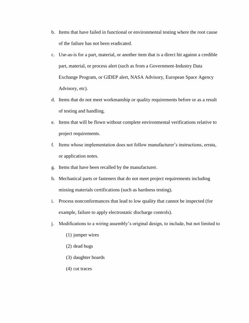
b. Items that have failed in functional or environmental testing where the root cause
of the failure has not been eradicated.
c. Use-as-is for a part, material, or another item that is a direct hit against a credible
part, material, or process alert (such as from a Government-Industry Data
Exchange Program, or GIDEP alert, NASA Advisory, European Space Agency
Advisory, etc).
d. Items that do not meet workmanship or quality requirements before or as a result
of testing and handling.
e. Items that will be flown without complete environmental verifications relative to
project requirements.
f. Items whose implementation does not follow manufacturer’s instructions, errata,
or application notes.
g. Items that have been recalled by the manufacturer.
h. Mechanical parts or fasteners that do not meet project requirements including
missing materials certifications (such as hardness testing).
i. Process nonconformances that lead to low quality that cannot be inspected (for
example, failure to apply electrostatic discharge controls).
j. Modifications to a wiring assembly’s original design, to include, but not limited to
(1) jumper wires
(2) dead bugs
(3) daughter boards
(4) cut traces

Note: The presence of these types of electronic packaging features, as a means to
realize an electrical design change without the penalty of redesigning the bare PCB
and rebuilding the printed wiring assembly (PWA), does not necessarily indicate on
its own that the design is not fully vetted or that the hardware carries heightened risk.
The SMA team needs to be made aware when a modified PWA has been “inherited,”
meaning that it has been fully characterized and vetted for the application and is
intended to be used-as-is, so that the unexpected features are not treated as new, un-
vetted repairs that require risk evaluation and thus are subsequently recorded as
nonconformances. An example of this is in the receipt of a commercial-off-the-shelf
component where such features would be fully expected and would not affect the
form, fit, or function of the device.
The project will provide supporting information for items that are suspected to have been
nonconforming as delivered (i.e., not due to end-user handling, processing, or storage) to the
supply chain management organization to follow up with the vendor and determine the cause for
the nonconforming item and the cause for the vendor having delivered a nonconforming item.
Keeping good records of supplier product quality issues via a supplier risk management process
is critical for determining whether the risk justifies greater SMA surveillance or involvement.
Prior to rebuilding or procuring an item that has been received in a nonconforming state, it is
important to ensure that the causes both for the nonconformance and for the quality escape have
been identified and mitigated or eliminated.
3.2 Out-of-Family Items
Out-of-family refers to items that meet all requirements while presenting performance in one or
more areas that is significantly different from that of the majority of the current population or
populations used in the past. Out-of-family behavior should prompt a risk assessment similarly
to nonconforming items because it may be a sign of something unexpected or different that may
lead to a previously uncharacterized degradation or failure mode. Out-of-family items should
prompt a follow-up with the vendor in many cases to determine the cause. In general, when out-
of-family items are determined to indicate a risk to the project, the nonconforming item process
in section 3.1 should be followed.
3.3 Balanced-Risk Practices
As a general principle, the development team should always be considering the risk of taking
actions vs. the risk of not taking actions. Part of this is a continuous process of questioning
requirements, particularly in cases where enforcing or implementing a requirement has the
potential for causing competing, previously unforeseen, risks or cost impacts. SMA teams
should vet these types of requirements with the requirements stakeholder (generally the
individual or organization that funds the effort and is expecting the return on investment in the
form of scientific achievement) to discover lower risk alternatives. Threats to hardware,
personnel, facilities, or the public should be identified by personnel from many disciplines,
including safety, reliability, software assurance, quality assurance, and others. Those threats that
are not mitigated with simple actions should be framed as risks and categorized as safety,
programmatic, or technical, as appropriate. It is essential to categorize risk appropriately since
the risk likelihood thresholds are different in each category using GSFC’s risk management
approach (NASA GSFC, 2012).
Many risks typically identified in hazard analysis by safety personnel are actually threats to
mission hardware prior to launch (programmatic risks, because recovery is possible) or threats to
hardware after launch (technical risks, because recovery is not possible), and these risks should
be treated commensurate with risks in the same respective categories. Treating risks to mission
hardware as safety risks may have the consequence of adding single point failures to the system
when there is no actual safety need to do so, thereby unnecessarily reducing reliability.
4.0 Contract Type Considerations
Note that the contract type is an important factor in the selection of safety and mission success
activities. Cost plus contracts rely significantly on oversight to ensure mission success and tend
to be a close teamwork effort between the government and the vendor. As such, the role of the
government is an oversight role, having authority at multiple levels for making decisions. Fixed
price contracts and those dependent on best commercial practices or off-the-shelf designs should
only be selected after a very careful review and assessment of the sufficiency of the vendor’s
historical processes for ensuring mission success within the stakeholder’s defined risk posture.
For fixed-price contracts, the role of the government is generally an insight role without
authority to make decisions at lower levels. Furthermore, the general trend when stepping from
Class A (lowest acceptable risk with highest National importance) down to a “do no harm”
(typically, a technology demonstration with tolerance for failure) risk posture, is one of less
prescription (more objectives-based) and less documentation, leaving more to the developer’s
standard practices. At the subcontract level, where the majority of the quality assurance
requirements are implemented, the supplier may not be under contract at all and may be
responding to a purchase order with limited or no NASA requirement flow down, as is the case
with commercial off-the-shelf items. Careful coordination with the prime contractor is required
in these instances when NASA has interest in looking at, or interacting closely with, the
supplier’s process or product prior to delivery, such as when investigating the root cause for
quality escapes or a failure. Distinguishing the roles and contract types is crucial to a successful
partnership between NASA and its supplier.
5.0 Representative Risk-based SMA results
In this Section we will provide several examples of how these risk-based SMA principles were
applied to improve the chance for mission success. These examples are summarized in the
following table:
5.1 PCB Coupon Nonconformance Handling
To ensure the structural and electrical integrity of bare PCBs, GSFC had long imposed the
standard-- Qualification and Performance Specification for Rigid Printed Boards, IPC 6012
Revision B Class 3/A, (IPC, 2004) and required structural integrity coupon microsections to
verify compliance. Between about 2000 and 2010, GSFC had been seeing a nonconformance
rate between about 20 and 30% across rigid PCBs, with some higher peaks at times. GSFC’s
approach was to treat the requirements in an absolute sense, although the standard itself suggests
that there should be flexibility in interpretation. This subsequently resulted in rejection of all
boards associated with nonconforming coupons, with few exceptions, as discussed below. It was
quite common to require three or four iterations of board fabrication, in many cases to result in
the determination that the first nonconforming board was the best out of all tries. There was no
determination of the risk in using a board with nonconformances, but the schedule hit would
frequently result in the loss of valuable system-level testing time as well as some boards
becoming critical path items. Furthermore, upon detailed review of the causes of the
nonconformance, it turned out that frequently, a different specification was flowed down through
notes on the pre-existing drawing, or the PCB supplier had moved on and baselined their
operations to the current version of the industry standard while GSFC was invoking an older,
superseded version. In 2014, after several cases where the impacts to projects were extreme,
focus was turned to the risk associated with common nonconformances. Upon determining very
low to nonexistent elevated risks due to common nonconformances, a policy was instituted that
required risk assessments to be performed on all nonconforming coupons. After roughly two
years with the policy applying to in-house development efforts, 193 circuit board lots were
assessed for risk, out of which 167 boards were selected to use-as-is, leaving 26 rejected
nonconforming lots (< 15% rejected out of all nonconformances). Based on the typical range of
costs for board manufacture and turnaround time, this resulted in a savings of between $400K
and $3.0M, with schedule savings between 300 and 1200 weeks for component developments.
Some such component developments were on the critical development path, representing
direct effect on the overall project schedule, while others had an effect on internal schedule
margins and reduced the time available to perform testing and verification activities. Note that
these cumulative schedule savings were enormous, but they are distributed over about 25
projects, and they are reflective of a high level of conservatism at the piece-part level that is
inherent in projects at GSFC. While in most cases the component level slips have little direct
effect on overall project schedules, the scrapping of items that entail minimal risk has the effect
of increasing overall project risk by removing valuable testing time. Very few printed circuit
board failures have occurred at GSFC over the past decade and none have been associated with
boards accepted through this process. Aside from the clear benefit of eliminating unnecessary
scrap, the process is one of continuous learning and improvement, where each risk assessment
builds upon the previous, and spawns testing efforts that feed back into the assessment process.
Initially, some of the assessments took four weeks or more, but after sufficient experience base,
comparable assessments can now be performed in hours or days.
5.2 Metrology and Calibration Requirements
In 2014, a review of audit and assessment findings identified a trend of a challenging closure
path associated with metrology and calibration internal and external findings. Furthermore, there
were growing complaints from the development community as well as many instances of testing
being seriously held up or disrupted by a Met/Cal concern. Review of a swath of these findings
indicated no risks associated with what were typically requirements violations that ranged from
the use of a box with an out-of-date calibration sticker through use of the wrong standard. These
facts combined to suggest that there was a requirements problem. A two-year investigation
revealed a range of issues with how Met/Cal requirements are imposed at GSFC, to include:
a. The lack of understanding about how Met/Cal applies across a large Center where
equipment is transient, going from project to project, location to location, and
environment to environment, where a sticker could never be sufficient to identify
whether a piece of equipment is properly calibrated for its current environment.
b. The lack of understanding that calibration is a means to ensure the accuracy of
measurements where accuracy is required, and not a means to guarantee that the
equipment functions properly.
c. The lack of understanding that in most cases in an environment with a multitude of
unique, specialized configurations, calibration of individual boxes is frequently
overcome by the condition of the setup (for example, it was common to require
power supplies to be calibrated and stickered, but they were frequently used with
long cabling and other electronics in the loop that effectively negated the calibration
in the location where accuracy was required).
d. The lack of understanding that the use of a different, but properly vetted, technical
requirements standard affected the efficiency associated with the calibration lab, but
not the risks associated with using calibrated equipment.
e. The fact that key measurements that require accuracy within a typical setup at
GSFC were not at the input or output of a particular box, but at some arbitrary
location within a configuration so that over-attention to calibration of individual
boxes took the attention away from the locations where accurate measurements
were actually required.
Subsequently, these issues were addressed through updates of both GSFC- and NASA-
level requirements. Ultimately, the result was to empower the user and development
community, rather than the Met/Cal service labs, to determine how to implement Met/Cal
requirements, not only saving significant money but enabling the Center to operate at an
overall lower level of risk. The agency followed suit by changing the higher-level
requirements as a result of our findings and actions.
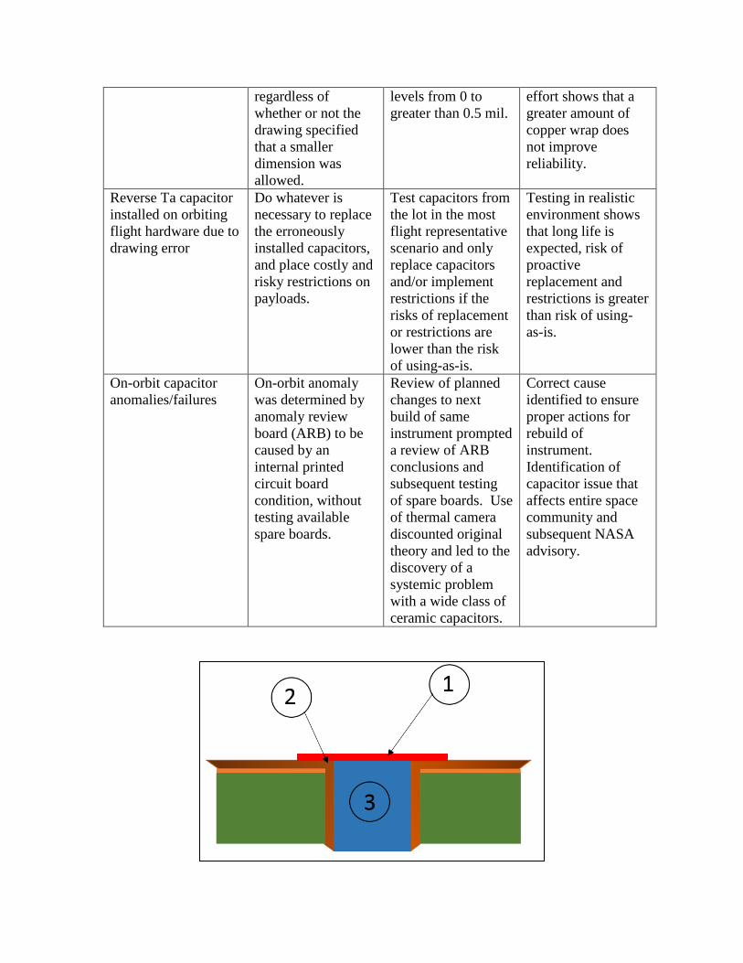
5.3 PCB Copper wrap violations
In our review of nonconforming PCB coupons, the minimum copper wrap (length and thickness)
requirement has been a persistent cause of board rejections. Copper wrap over vias in the board
is shown in cross-section view in Figure 1.
The requirement emphasized both a two-surface contact of the wrap plating layer (both with the
hole wall and the top-side annular ring plating) rather than a one-surface butt joint, as well as a
minimum thickness for the section on the top surface (above the annular ring plating and
measured 1 mil from the hole wall) connecting both features to increase PCB reliability. Two
root causes were found for the most common nonconformances: (1) the planarization process
used to optimize the panel’s surface flatness after the plating process reduces the wrap thickness
with a ±60% accuracy (a panel can contain multiple boards), and (2) the requirement was not
included in alternate standards used at the time for some builds (for example, the European
Space Agency’s ECSS-Q-ST-70-11C instead of IPC-6012B Class 3/A).
During the development process for the Ice, Cloud, and land Elevation Satellite (ICESat)-II
mission, the problem of copper wrap nonconformance once again emerged, this time affecting a
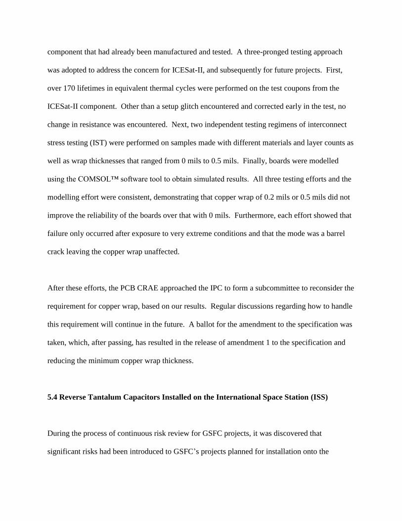
component that had already been manufactured and tested. A three-pronged testing approach
was adopted to address the concern for ICESat-II, and subsequently for future projects. First,
over 170 lifetimes in equivalent thermal cycles were performed on the test coupons from the
ICESat-II component. Other than a setup glitch encountered and corrected early in the test, no
change in resistance was encountered. Next, two independent testing regimens of interconnect
stress testing (IST) were performed on samples made with different materials and layer counts as
well as wrap thicknesses that ranged from 0 mils to 0.5 mils. Finally, boards were modelled
using the COMSOL™ software tool to obtain simulated results. All three testing efforts and the
modelling effort were consistent, demonstrating that copper wrap of 0.2 mils or 0.5 mils did not
improve the reliability of the boards over that with 0 mils. Furthermore, each effort showed that
failure only occurred after exposure to very extreme conditions and that the mode was a barrel
crack leaving the copper wrap unaffected.
After these efforts, the PCB CRAE approached the IPC to form a subcommittee to reconsider the
requirement for copper wrap, based on our results. Regular discussions regarding how to handle
this requirement will continue in the future. A ballot for the amendment to the specification was
taken, which, after passing, has resulted in the release of amendment 1 to the specification and
reducing the minimum copper wrap thickness.
5.4 Reverse Tantalum Capacitors Installed on the International Space Station (ISS)
During the process of continuous risk review for GSFC projects, it was discovered that
significant risks had been introduced to GSFC’s projects planned for installation onto the
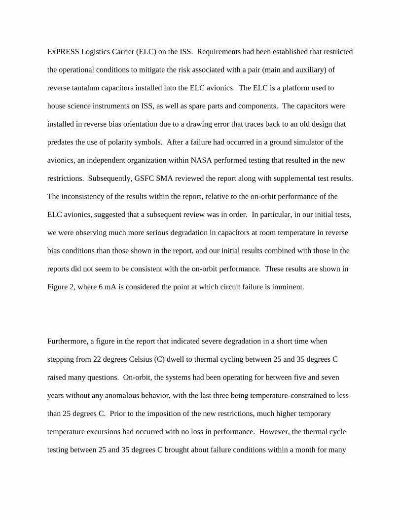
ExPRESS Logistics Carrier (ELC) on the ISS. Requirements had been established that restricted
the operational conditions to mitigate the risk associated with a pair (main and auxiliary) of
reverse tantalum capacitors installed into the ELC avionics. The ELC is a platform used to
house science instruments on ISS, as well as spare parts and components. The capacitors were
installed in reverse bias orientation due to a drawing error that traces back to an old design that
predates the use of polarity symbols. After a failure had occurred in a ground simulator of the
avionics, an independent organization within NASA performed testing that resulted in the new
restrictions. Subsequently, GSFC SMA reviewed the report along with supplemental test results.
The inconsistency of the results within the report, relative to the on-orbit performance of the
ELC avionics, suggested that a subsequent review was in order. In particular, in our initial tests,
we were observing much more serious degradation in capacitors at room temperature in reverse
bias conditions than those shown in the report, and our initial results combined with those in the
reports did not seem to be consistent with the on-orbit performance. These results are shown in
Figure 2, where 6 mA is considered the point at which circuit failure is imminent.
Furthermore, a figure in the report that indicated severe degradation in a short time when
stepping from 22 degrees Celsius (C) dwell to thermal cycling between 25 and 35 degrees C
raised many questions. On-orbit, the systems had been operating for between five and seven
years without any anomalous behavior, with the last three being temperature-constrained to less
than 25 degrees C. Prior to the imposition of the new restrictions, much higher temporary
temperature excursions had occurred with no loss in performance. However, the thermal cycle
testing between 25 and 35 degrees C brought about failure conditions within a month for many
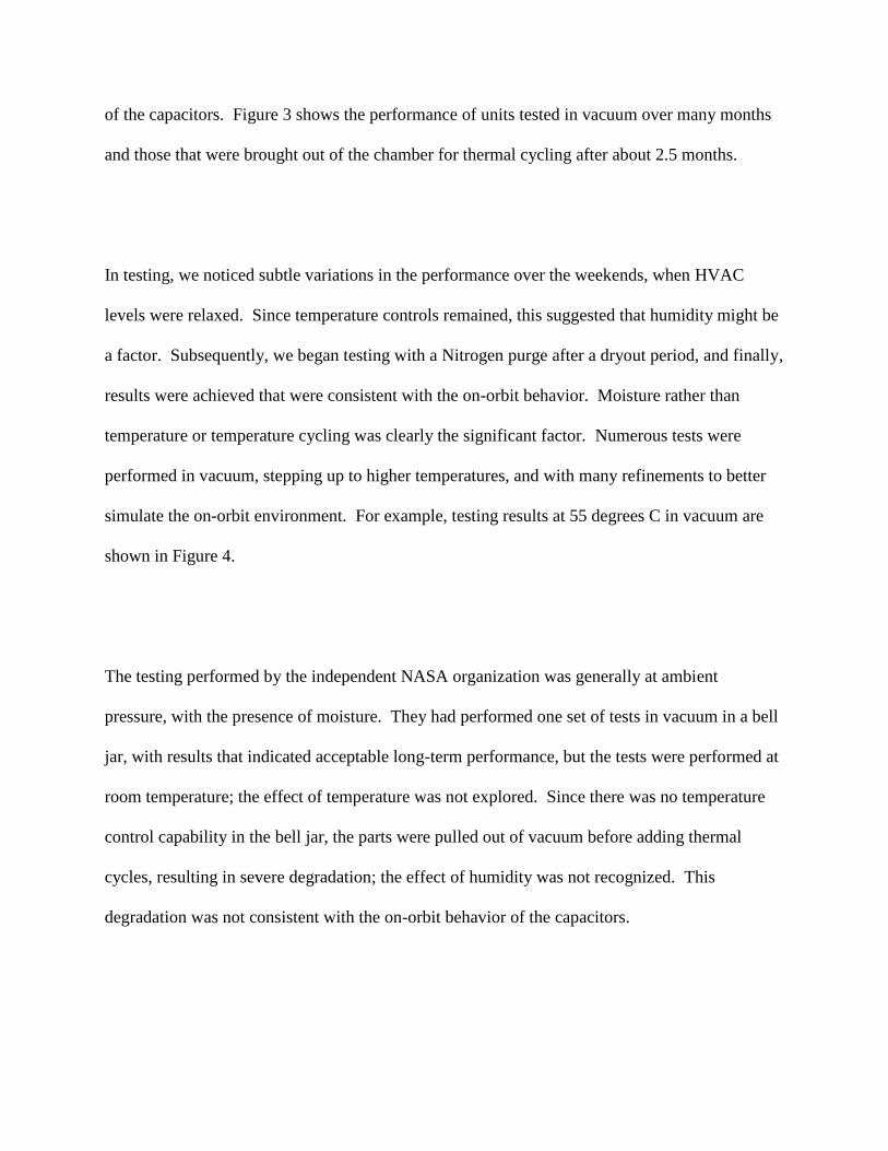
of the capacitors. Figure 3 shows the performance of units tested in vacuum over many months
and those that were brought out of the chamber for thermal cycling after about 2.5 months.
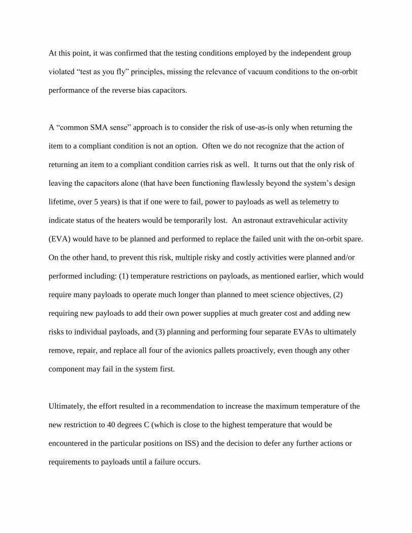
In testing, we noticed subtle variations in the performance over the weekends, when HVAC
levels were relaxed. Since temperature controls remained, this suggested that humidity might be
a factor. Subsequently, we began testing with a Nitrogen purge after a dryout period, and finally,
results were achieved that were consistent with the on-orbit behavior. Moisture rather than
temperature or temperature cycling was clearly the significant factor. Numerous tests were
performed in vacuum, stepping up to higher temperatures, and with many refinements to better
simulate the on-orbit environment. For example, testing results at 55 degrees C in vacuum are
shown in Figure 4.
The testing performed by the independent NASA organization was generally at ambient
pressure, with the presence of moisture. They had performed one set of tests in vacuum in a bell
jar, with results that indicated acceptable long-term performance, but the tests were performed at
room temperature; the effect of temperature was not explored. Since there was no temperature
control capability in the bell jar, the parts were pulled out of vacuum before adding thermal
cycles, resulting in severe degradation; the effect of humidity was not recognized. This
degradation was not consistent with the on-orbit behavior of the capacitors.
At this point, it was confirmed that the testing conditions employed by the independent group
violated “test as you fly” principles, missing the relevance of vacuum conditions to the on-orbit
performance of the reverse bias capacitors.
A “common SMA sense” approach is to consider the risk of use-as-is only when returning the
item to a compliant condition is not an option. Often we do not recognize that the action of
returning an item to a compliant condition carries risk as well. It turns out that the only risk of
leaving the capacitors alone (that have been functioning flawlessly beyond the system’s design
lifetime, over 5 years) is that if one were to fail, power to payloads as well as telemetry to
indicate status of the heaters would be temporarily lost. An astronaut extravehicular activity
(EVA) would have to be planned and performed to replace the failed unit with the on-orbit spare.
On the other hand, to prevent this risk, multiple risky and costly activities were planned and/or
performed including: (1) temperature restrictions on payloads, as mentioned earlier, which would
require many payloads to operate much longer than planned to meet science objectives, (2)
requiring new payloads to add their own power supplies at much greater cost and adding new
risks to individual payloads, and (3) planning and performing four separate EVAs to ultimately
remove, repair, and replace all four of the avionics pallets proactively, even though any other
component may fail in the system first.
Ultimately, the effort resulted in a recommendation to increase the maximum temperature of the
new restriction to 40 degrees C (which is close to the highest temperature that would be
encountered in the particular positions on ISS) and the decision to defer any further actions or
requirements to payloads until a failure occurs.
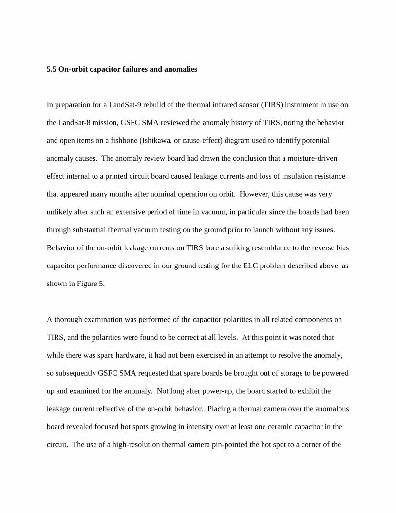
5.5 On-orbit capacitor failures and anomalies
In preparation for a LandSat-9 rebuild of the thermal infrared sensor (TIRS) instrument in use on
the LandSat-8 mission, GSFC SMA reviewed the anomaly history of TIRS, noting the behavior
and open items on a fishbone (Ishikawa, or cause-effect) diagram used to identify potential
anomaly causes. The anomaly review board had drawn the conclusion that a moisture-driven
effect internal to a printed circuit board caused leakage currents and loss of insulation resistance
that appeared many months after nominal operation on orbit. However, this cause was very
unlikely after such an extensive period of time in vacuum, in particular since the boards had been
through substantial thermal vacuum testing on the ground prior to launch without any issues.
Behavior of the on-orbit leakage currents on TIRS bore a striking resemblance to the reverse bias
capacitor performance discovered in our ground testing for the ELC problem described above, as
shown in Figure 5.
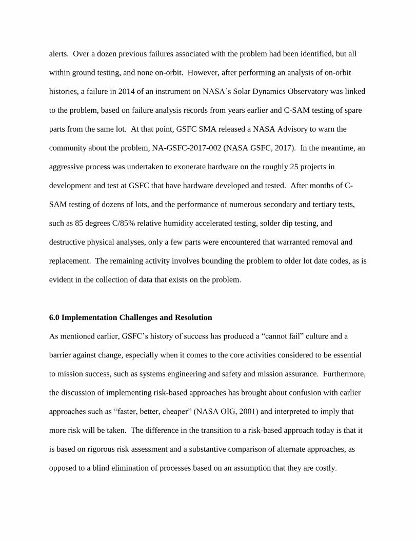
A thorough examination was performed of the capacitor polarities in all related components on
TIRS, and the polarities were found to be correct at all levels. At this point it was noted that
while there was spare hardware, it had not been exercised in an attempt to resolve the anomaly,
so subsequently GSFC SMA requested that spare boards be brought out of storage to be powered
up and examined for the anomaly. Not long after power-up, the board started to exhibit the
leakage current reflective of the on-orbit behavior. Placing a thermal camera over the anomalous
board revealed focused hot spots growing in intensity over at least one ceramic capacitor in the
circuit. The use of a high-resolution thermal camera pin-pointed the hot spot to a corner of the

capacitor, highly indicative of a crack. While cracks in ceramic capacitors have been somewhat
common, we had not known of a case of one that was not discovered upon installation or during
integration and test. Inspection of the part on the spare board and removal of the part gave no
indications of an external crack. The thermal image is shown in Figure 6. Two capacitors that
developed low insulation resistance during testing of the spare boards were carefully-removed
from the board and subjected to detailed failure analysis. In each case the anomalous capacitor
contained an internal delamination between an electrode and the ceramic dielectric. Furthermore,
each capacitor exhibited an internal crack in the ceramic dielectric that was coincident with the
delamination and extended between two adjacent electrode plates. Both the delamination and the
crack features were self-contained within the capacitor chip (i.e., there were no externally-visible
cracks). Internal delaminations and cracks that extend between the anode and cathode provide
conduits within which electrically-conductive leakage paths may develop over time under bias.
Fortunately, the project had hundreds of spare parts from the same lot date code in inventory that
would be useful for characterizing the lot. C-Mode Scanning Acoustic Microscopy (C-SAM),
was performed on the lot to determine whether there were internal flaws in the pristine parts,
such as voids or delaminations. The C-SAM results for over 300 residual parts revealed
delaminations in around 50% of the parts in the lot. The task forward would be to link the
delaminations in the spare parts with the anomalous parts on-orbit and on the spare board on the
ground. The subsequent investigation revealed that this had been a long-standing problem,
known in some communities, but not well-reported, without any broadly-published product
alerts. Over a dozen previous failures associated with the problem had been identified, but all
within ground testing, and none on-orbit. However, after performing an analysis of on-orbit
histories, a failure in 2014 of an instrument on NASA’s Solar Dynamics Observatory was linked
to the problem, based on failure analysis records from years earlier and C-SAM testing of spare
parts from the same lot. At that point, GSFC SMA released a NASA Advisory to warn the
community about the problem, NA-GSFC-2017-002 (NASA GSFC, 2017). In the meantime, an
aggressive process was undertaken to exonerate hardware on the roughly 25 projects in
development and test at GSFC that have hardware developed and tested. After months of C-
SAM testing of dozens of lots, and the performance of numerous secondary and tertiary tests,
such as 85 degrees C/85% relative humidity accelerated testing, solder dip testing, and
destructive physical analyses, only a few parts were encountered that warranted removal and
replacement. The remaining activity involves bounding the problem to older lot date codes, as is
evident in the collection of data that exists on the problem.
6.0 Implementation Challenges and Resolution
As mentioned earlier, GSFC’s history of success has produced a “cannot fail” culture and a
barrier against change, especially when it comes to the core activities considered to be essential
to mission success, such as systems engineering and safety and mission assurance. Furthermore,
the discussion of implementing risk-based approaches has brought about confusion with earlier
approaches such as “faster, better, cheaper” (NASA OIG, 2001) and interpreted to imply that
more risk will be taken. The difference in the transition to a risk-based approach today is that it
is based on rigorous risk assessment and a substantive comparison of alternate approaches, as
opposed to a blind elimination of processes based on an assumption that they are costly.
6.1 Changing the culture
In order to get past the fear of failure associated with such change, it has been essential to
perform continuous and persistent training at all levels in the organization, centered on real
examples from pilot project implementation and from testing performed. At the core of the risk-
based approach is a thorough understanding of risk, and while GSFC has been using risk
management for well over a decade, there was not a rigorous and consistent approach for
assessing and managing risk across the Center. The rigor and consistency are essential to
effective risk-based SMA implementation, especially when some longstanding and long-trusted
requirements are being displaced or diminished in authority, so this brought about further need
for developing guidelines, building examples, and training development engineers and SMA
personnel to understand and manage risk. A key element of this is promoting the understanding
of the risks that come with implementing requirements as well as their effectiveness for buying
down risks in operation (i.e., in space where in most cases hardware cannot be repaired). One of
the biggest challenges has been reducing some of the conservatism at the piece-part level in
exchange for more rigorous system-level analysis including fault-tolerance. The piece-part
conservatism has become an artifact of the organizational structure with subject matter experts
for a range of individual areas, such as electronic parts, printed circuit boards, materials, etc., that
have traditionally had nearly-unfettered ownership of their elements among each of the projects.
For highly-resource-constrained missions, piece-part conservatism has frequently led to reduced
system-level testing because of long screening times, the need to respond to screening anomalies
whose effects in the application are not clear, and occasional overtesting. This is one example of
trading resources (e.g., costs and time to performing screening) and programmatic risk (e.g.,
risks that screening processes will take longer than expected or cost more because you damage
something) to buy down technical risk (risk of a failure when on-orbit). This is an example of an
essential risk trade that must be understood for the most effective implementation of
requirements. In support of, and beyond, the substantive assessment of risk necessary to
convince the GSFC community to take a risk-based approach has been detailed assessment of
data from integration and test, and on-orbit, as well as the collection of data from specially-
designed tests in relevant scenarios. In Section 6.2 we will summarize the results to identify key
collective take-aways from each of the example areas.
6.2 Discussion of Findings
We have described five major mission assurance challenges that could have taken a very
different path to closure based on traditional practices of GSFC and NASA as a whole. In each
of these instances, the traditional path was not likely to have led to hardware failure; however,
the programmatic risk would have increased (i.e., cost and schedule growth). In 2014, after
several cases where the impacts to projects were extreme, focus was turned to the risk associated
with common nonconformances. Upon determining very low to nonexistent elevated risks due to
common nonconformances, a policy was instituted that eventually required risk assessments to
be performed on all nonconforming coupons. This ended up reducing scrap by about 85% and
saved substantial schedule, resulting in not only cost savings but savings of key time allocated to
system level testing. This involved steering away from the long-standing core assumption that
high rates of nonconformance necessarily indicate an industry or manufacturing problem that
drives up the risk of product failure. It also revisited the need to support standard technical
requirements that are imposed broadly, with empirical evidence of their value and effectiveness.
It showed that without technical rigor in the rationale used to establish them, these requirements
could actually be counterproductive by unnecessarily driving up cost or reducing reliability. In
the same time frame, the huge burden of nonconformances in the areas of metrology and
calibration led to a detailed investigation and a complete transformation of an approach based on
empowering the user and development community, rather than the Met/Cal service labs, to
determine how to implement Met/Cal requirements, not only saving significant money but
enabling the Center to operate at an overall lower level of risk. The agency followed suit by
changing the higher-level requirements as a result of our findings and actions. After some time
implementing the printed circuit board risk assessment process, a common theme of
manufacturing challenges in meeting the copper wrap requirement emerged, highlighted in a
high risk that had been burdening the ICESat-2 project. This prompted a rigorous, multi-pronged
testing regimen that ultimately showed that reliability was not improved by meeting the
requirement, resulting in closure and a requirements update in the standard. In parallel, the
NICER project on the International Space Station had become burdened by a late-breaking
requirement to address a reverse polarity tantalum capacitor installed in the ExPRESS Logistics
Carrier platform to which it would ultimately be installed, prompting detailed risk assessments
and development of a range of rigorous tests. In this example, safety risk would have increased
if astronaut Extra-Vehicular Activities were selected to achieve closure. Ultimately the ISS
program decided to raise the maximum allowable temperature for the ELC users and eliminate
further EVA plans, reducing cost and risk substantially across the board. Finally, the ceramic
capacitor problem experienced on two GSFC missions on-orbit has brought about lessons in
using all data to characterize an anomaly that has broad implications and using all resources
available to try to recreate the anomaly. In particular, when drawing conclusions that drive
costly corrective actions that also have associated risk, be sure that all available data have been
exhausted. Furthermore, this problem and resulting investigation exposed a longstanding
problem that has existed with information transfer about known problems across the space
community.
Although the long-standing practices that were challenged in these examples normally evolve out
of past experiences within specific contexts (lessons learned) they can ignore the big picture
view of risk and discourage new testing and new analyses of the prior data. Lessons learned are
extremely valuable when the context is the same but can create solution bias when the context is
sufficiently similar. Some relatively straightforward analyses were used to steer away from these
well-intentioned paths and onto paths of lower risk while saving multiple millions of dollars and
hundreds of weeks of project schedule.
7.0 Summary and Conclusions
This paper has presented a risk-based SMA framework that prioritizes understanding all sides of
risk for a given problem as opposed to applying a bias toward compliance with quality
requirements after a problem has occurred. Standard SMA requirements are a normalization of
lessons learned and serve to streamline communication of expectations between customers and
suppliers. They facilitate the plan and implementation of analyses and controls that maximize
first-pass compliance. These examples show that once noncompliance has occurred, the SMA
requirements may no longer be as useful as careful analysis and risk management. While NASA
routinely uses material review boards, failure review boards, and anomaly review boards to
understand the nature and impact of nonconformances, there is a bias towards returning the item
to a state of conformance without consideration of the risk of doing so. This bias competes with
performing deeper investigations of existing and new data to understand options and risks.
Process nonconformance is often equated with a lack of commitment to the requirements, or
complacency, rather than considering if the nonconformance is actually feedback indicating a
shortcoming in the requirement itself. Lessons learned are at the core of the methodology and
are inherent in all activities but carry specific context that must be recognized. The examples
presented demonstrate not only that the risk-based approach is effective at saving cost and
schedule resources, but that it enables any project to operate at the lowest possible risk posture
given its particular resource constraints.
8.0 References
1. IPC (Association Connecting Electronics Industries), IPC 6012 Revision B, Qualification
and Performance Specification for Rigid Printed Boards, August, 2004.
2. NASA Goddard Space Flight Center, Goddard Procedural Requirements 8705.4, Risk
Classification Guidelines and Risk-Based SMA Practices for GSFC Payloads and
Systems, June 2016.
3. NASA Goddard Space Flight Center, Goddard Procedural Requirements 8730.5,
Safety and Mission Assurance Acceptance of Inherited and Build-to-Print Products,
March 2016.
4. NASA Goddard Space Flight Center, GSFC-HDBK-8005, Guideline for Performing Risk
Assessments, October 2017.
5. NASA Goddard Space Flight Center, Goddard Procedural Requirements 7120.4, Risk
Management, August 2012.
6. NASA Office of the Inspector General, “Faster, Better, Cheaper: Policy, Strategic
Planning, and Human Resource Alignment, IG-01-009, March 13, 2001.
7. NASA Goddard Space Flight Center, Multilayer Ceramic Capacitors with Internal
Delaminations and Cracks Leading to Reduced Insulation Resistance Failure Modes in
Service, NASA Advisory NA-GSFC-2017-02, June 2017.
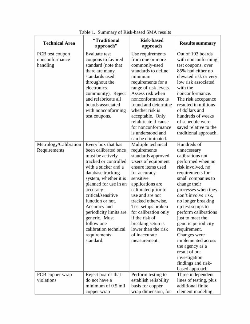
Table 1. Summary of Risk-based SMA results
Technical Area “Traditional
approach”
Risk-based
approach Results summary
PCB test coupon
nonconformance
handling
Evaluate test
coupons to favored
standard (note that
there are many
standards used
throughout the
electronics
community). Reject
and refabricate all
boards associated
with nonconforming
test coupons.
Use requirements
from one or more
commonly-used
standards to define
minimum
requirements for a
range of risk levels.
Assess risk when
nonconformance is
found and determine
whether risk is
acceptable. Only
refabricate if cause
for nonconformance
is understood and
can be eliminated.
Out of 193 boards
with nonconforming
test coupons, over
85% had either no
elevated risk or very
low risk associated
with the
nonconformance.
The risk acceptance
resulted in millions
of dollars and
hundreds of weeks
of schedule were
saved relative to the
traditional approach.
Metrology/Calibration
Requirements
Every box that has
been calibrated once
must be actively
tracked or controlled
with a sticker and a
database tracking
system, whether it is
planned for use in an
accuracy-
critical/sensitive
function or not.
Accuracy and
periodicity limits are
generic. Must
follow one
calibration technical
requirements
standard.
Multiple technical
requirements
standards approved.
Users of equipment
ensure items used
for accuracy-
sensitive
applications are
calibrated prior to
use and are not
tracked otherwise.
Test setups broken
for calibration only
if the risk of
breaking setup is
lower than the risk
of inaccurate
measurement.
Hundreds of
unnecessary
calibrations not
performed when no
risk involved, no
requirements for
small companies to
change their
processes when they
don’t involve risk,
no longer breaking
up test setups to
perform calibrations
just to meet the
generic periodicity
requirement.
Changes were
implemented across
the agency as a
result of our
investigation
findings and risk-
based approach.
PCB copper wrap
violations
Reject boards that
do not have a
minimum of 0.5 mil
copper wrap
Perform testing to
establish reliability
basis for copper
wrap dimension, for
Three independent
lines of testing, plus
additional finite
element modeling
regardless of
whether or not the
drawing specified
that a smaller
dimension was
allowed.
levels from 0 to
greater than 0.5 mil.
effort shows that a
greater amount of
copper wrap does
not improve
reliability.
Reverse Ta capacitor
installed on orbiting
flight hardware due to
drawing error
Do whatever is
necessary to replace
the erroneously
installed capacitors,
and place costly and
risky restrictions on
payloads.
Test capacitors from
the lot in the most
flight representative
scenario and only
replace capacitors
and/or implement
restrictions if the
risks of replacement
or restrictions are
lower than the risk
of using-as-is.
Testing in realistic
environment shows
that long life is
expected, risk of
proactive
replacement and
restrictions is greater
than risk of using-
as-is.
On-orbit capacitor
anomalies/failures
On-orbit anomaly
was determined by
anomaly review
board (ARB) to be
caused by an
internal printed
circuit board
condition, without
testing available
spare boards.
Review of planned
changes to next
build of same
instrument prompted
a review of ARB
conclusions and
subsequent testing
of spare boards. Use
of thermal camera
discounted original
theory and led to the
discovery of a
systemic problem
with a wide class of
ceramic capacitors.
Correct cause
identified to ensure
proper actions for
rebuild of
instrument.
Identification of
capacitor issue that
affects entire space
community and
subsequent NASA
advisory.
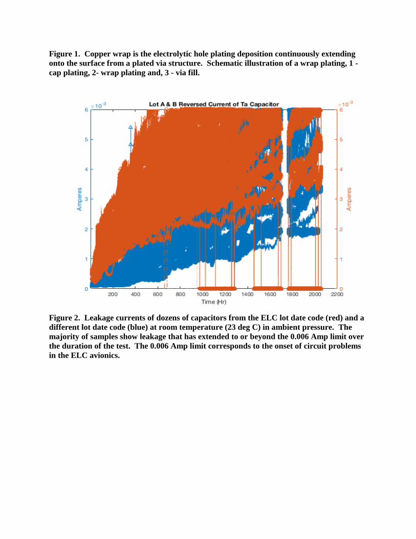
Figure 1. Copper wrap is the electrolytic hole plating deposition continuously extending
onto the surface from a plated via structure. Schematic illustration of a wrap plating, 1 -
cap plating, 2- wrap plating and, 3 - via fill.
Figure 2. Leakage currents of dozens of capacitors from the ELC lot date code (red) and a
different lot date code (blue) at room temperature (23 deg C) in ambient pressure. The
majority of samples show leakage that has extended to or beyond the 0.006 Amp limit over
the duration of the test. The 0.006 Amp limit corresponds to the onset of circuit problems
in the ELC avionics.

Figure 3. Leakage currents of all capacitors tested in vacuum until mid-June. Those that
start to rise after mid-June were taken from the chamber and cycled between 25 and 35
deg C in ambient pressure. The 0.006 Amp level was determined to represent the onset of
circuit problems in the ELC avionics.
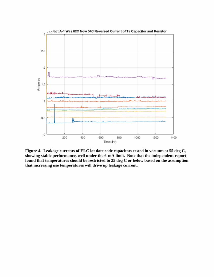
Figure 4. Leakage currents of ELC lot date code capacitors tested in vacuum at 55 deg C,
showing stable performance, well under the 6-mA limit. Note that the independent report
found that temperatures should be restricted to 25 deg C or below based on the assumption
that increasing use temperatures will drive up leakage current.
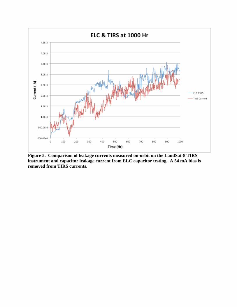
Figure 5. Comparison of leakage currents measured on-orbit on the LandSat-8 TIRS
instrument and capacitor leakage current from ELC capacitor testing. A 54 mA bias is
removed from TIRS currents.
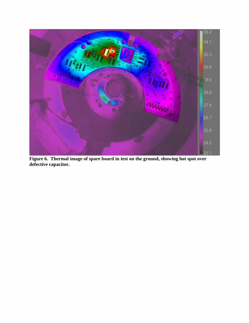
Figure 6. Thermal image of spare board in test on the ground, showing hot spot over
defective capacitor.