Embed Size (px)
Citation preview
1SINTEF Energy Research
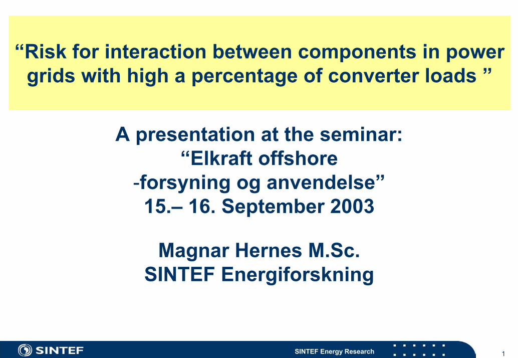
“Risk for interaction between components in power grids with high a percentage of converter loads ”
A presentation at the seminar:“Elkraft offshore
-forsyning og anvendelse”15.– 16. September 2003
Magnar Hernes M.Sc.SINTEF Energiforskning
2SINTEF Energy Research
Power electronic equipment appears as non-linear components in the power grid
Examples of such equipment is variable speed motor drives (VSD) and uninterruptible power supplies (UPS)The degree of non-linearity depends on the power circuit of the converter, as seen from the grid, and the control system for theconverter The risk for operational problems increases with increasing percentage of converter load (converter power relative to the short circuit level for the grid)
3SINTEF Energy Research
Examples of operational problems in grids with high percentage of converter load
Overharmonics- E.g. from 6-pulse og 12-pulse diode- and thyristor rectifiersHigh-frequency noise (”radio noise”) from converters with high-frequency switching transistors and thyristors (IGBT, GTO)Stability problems due to converter control
E.g. from converters with constant power controlInteraction between components in the grid
E.g. sub-synchronous resonance where mechanical natural frequencies within rotating equipment is excited by interharmonics from converters for variable speed drives (VSD)
4SINTEF Energy Research
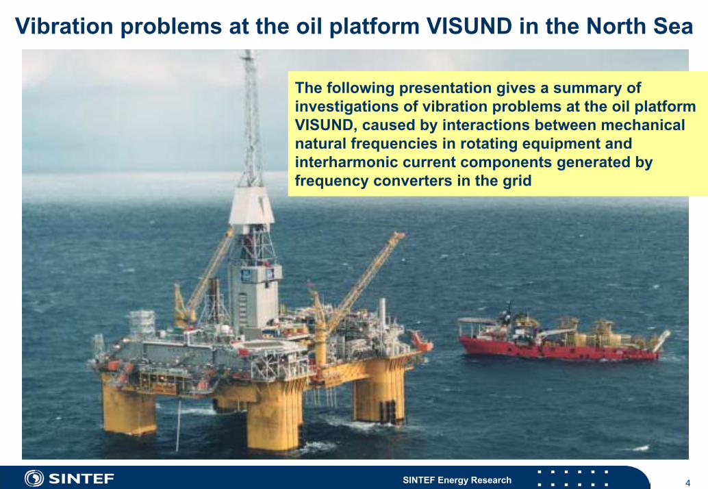
Vibration problems at the oil platform VISUND in the North Sea
The following presentation gives a summary of investigations of vibration problems at the oil platform VISUND, caused by interactions between mechanical natural frequencies in rotating equipment andinterharmonic current components generated by frequency converters in the grid
5SINTEF Energy Research
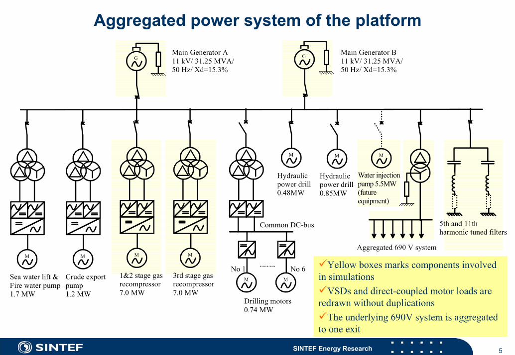
Aggregated power system of the platform
M
Sea water lift &Fire water pump1.7 MW
M
Crude export pump 1.2 MW
M
1&2 stage gasrecompressor 7.0 MW
M
3rd stage gasrecompressor7.0 MW
M
Drilling motors0.74 MW
M
No 1 No 6
M
Hydraulicpower drill0.48MW
M
Hydraulicpower drill0.85MW
Common DC-bus
Aggregated 690 V system
5th and 11thharmonic tuned filters
G G Main Generator B11 kV/ 31.25 MVA/50 Hz/ Xd=15.3%
Main Generator A11 kV/ 31.25 MVA/50 Hz/ Xd=15.3%
M
Water injectionpump 5.5MW(future equipment)
Yellow boxes marks components involved in simulations
VSDs and direct-coupled motor loads are redrawn without duplications
The underlying 690V system is aggregated to one exit
6SINTEF Energy Research
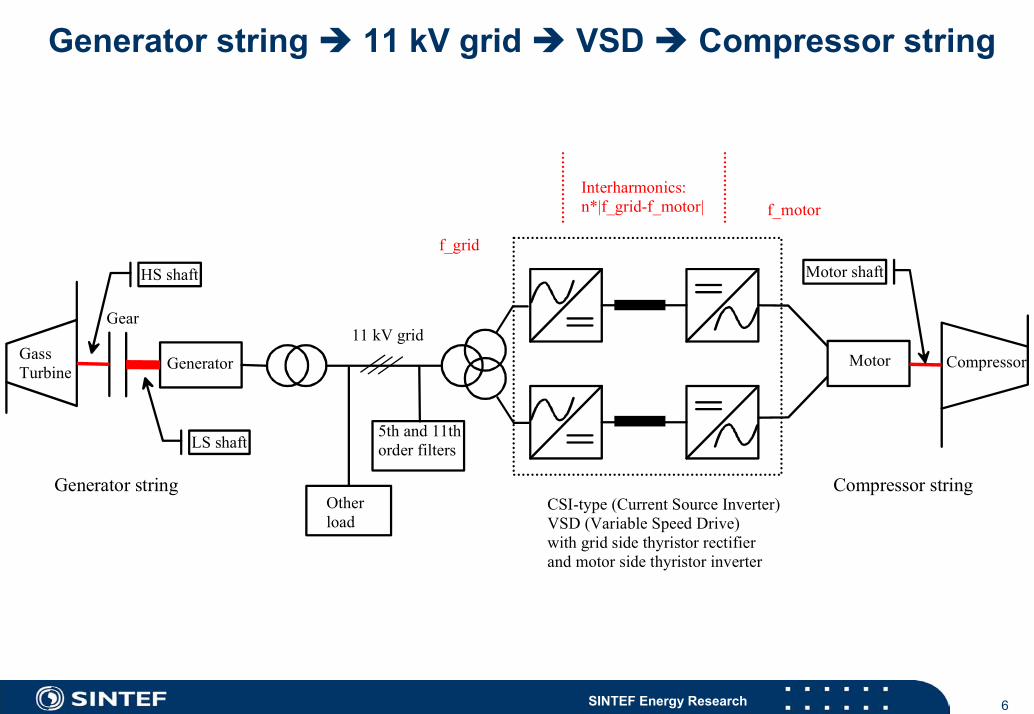
Generator string 11 kV grid VSD Compressor string
CSI-type (Current Source Inverter)VSD (Variable Speed Drive)with grid side thyristor rectifierand motor side thyristor inverter
GassTurbine
Gear
HS shaft
LS shaft
Generator
11 kV grid
5th and 11thorder filters
Other load
Motor shaft
Motor Compressor
f_grid
f_motorInterharmonics:n*|f_grid-f_motor|
Generator string Compressor string
7SINTEF Energy Research
Problem-description
Norsk Hydro has periodically experienced severe vibration problems within the power generators at some of their oil platforms in the North SeaInitially these problems were believed to have a pure mechanicalnature, and actions like modifications of a gear shaft (quill shaft), thereby increasing the inherent mechanical damping of the turbine generator trains (TG trains), was carried outBecause these modifications did only partly solve the problems, SINTEF recommended to focus on possible sources for the problemswithin the electric grid, especially to two large current source variable speed drives (VSDs)Then it was decided to engage SINTEF for the clarification of possible interaction from the power grid. For this purpose the simulationprogram PSCAD/ EMTDC was used
8SINTEF Energy Research
Two types of problems experienced
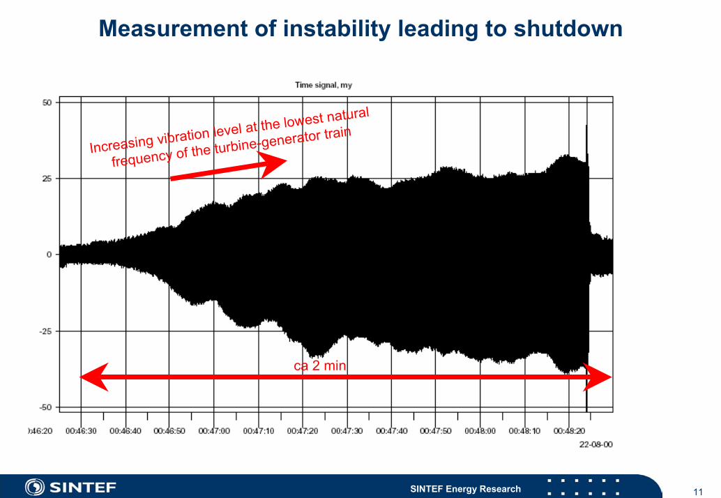
One had a transient character, and has been found to coincide with certain operating speeds of two 7 MW VSD driven compressor drives The other phenomenon has only occurred a few times, but is more serious since it leads to power shutdown of the platform. It is experienced as a slowly increasing vibration, which develops over some time (a couple of minutes) to inadmissible levels, finally tripping the generator
9SINTEF Energy Research
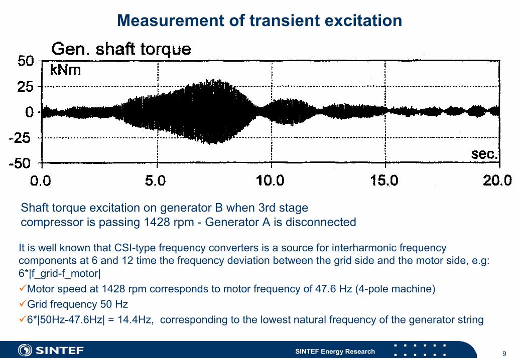
Measurement of transient excitation
Shaft torque excitation on generator B when 3rd stagecompressor is passing 1428 rpm - Generator A is disconnected
It is well known that CSI-type frequency converters is a source for interharmonic frequency components at 6 and 12 time the frequency deviation between the grid side and the motor side, e.g: 6*|f_grid-f_motor|
Motor speed at 1428 rpm corresponds to motor frequency of 47.6 Hz (4-pole machine)Grid frequency 50 Hz6*|50Hz-47.6Hz| = 14.4Hz, corresponding to the lowest natural frequency of the generator string
10SINTEF Energy Research
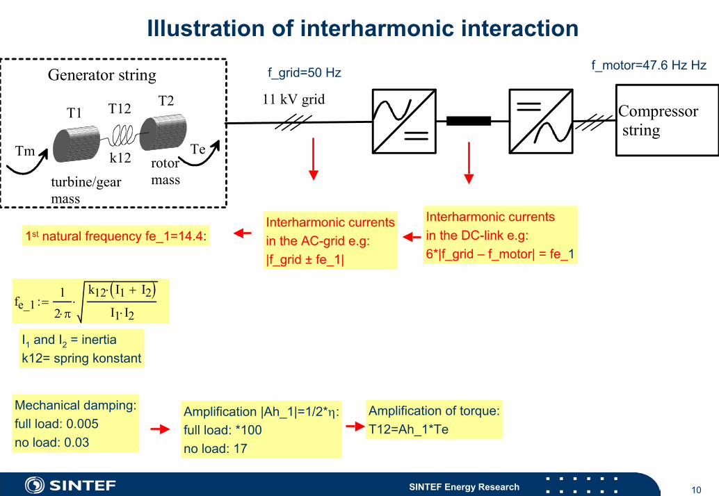
Illustration of interharmonic interaction
T1T2T12
turbine/gearmass
rotormass
Tm Te
11 kV gridGenerator string
Compressor string
k12
f_grid=50 Hz f_motor=47.6 Hz Hz
Interharmonic currentsin the DC-link e.g:6*|f_grid – f_motor| = fe_1
Interharmonic currentsin the AC-grid e.g:|f_grid ± fe_1|
1st natural frequency fe_1=14.4:
fe_11
2 π⋅
k12 I1 I2+( )⋅
I1 I2⋅⋅:=
I1 and I2 = inertiak12= spring konstant
Mechanical damping:full load: 0.005no load: 0.03
Amplification of torque:T12=Ah_1*Te
Amplification |Ah_1|=1/2*η:full load: *100no load: 17
11SINTEF Energy Research
Measurement of instability leading to shutdown
Increasing vibration level at the lowest natural
frequency of the turbine-generator train
ca 2 min
12SINTEF Energy Research
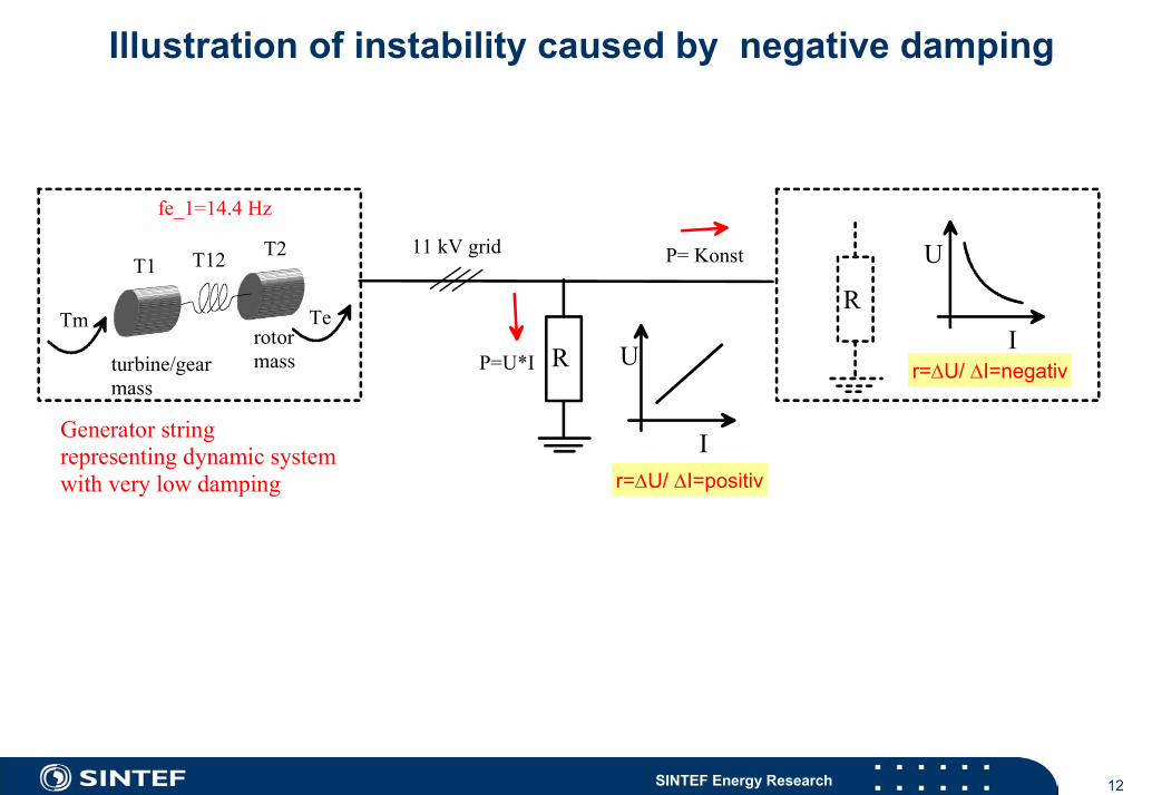
Illustration of instability caused by negative damping
T1T2T12
turbine/gearmass
rotormass
Tm Te
fe_1=14.4 Hz
11 kV grid
R U
IGenerator stringrepresenting dynamic systemwith very low damping
P=U*I
P= Konst U
IR
r=∆U/ ∆I=positiv
r=∆U/ ∆I=negativ
13SINTEF Energy Research
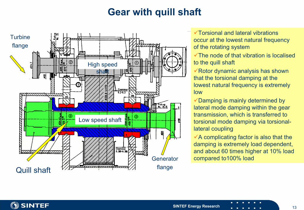
Gear with quill shaft
Turbineflange
GeneratorflangeQuill shaft
High speed shaft
Low speed shaft
Torsional and lateral vibrations occur at the lowest natural frequencyof the rotating system
The node of that vibration is localisedto the quill shaft
Rotor dynamic analysis has shown that the torsional damping at thelowest natural frequency is extremelylow
Damping is mainly determined bylateral mode damping within the geartransmission, which is transferred totorsional mode damping via torsional-lateral coupling
A complicating factor is also that thedamping is extremely load dependent, and about 60 times higher at 10% load compared to100% load
14SINTEF Energy Research
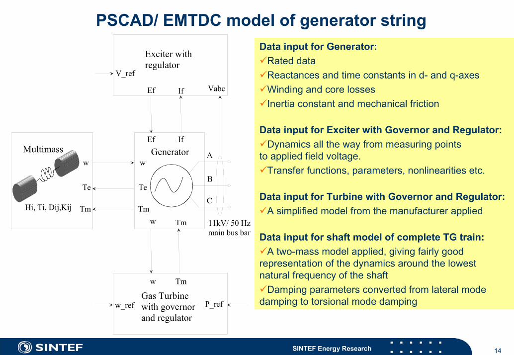
PSCAD/ EMTDC model of generator stringData input for Generator:
Rated dataReactances and time constants in d- and q-axesWinding and core lossesInertia constant and mechanical friction
Data input for Exciter with Governor and Regulator:Dynamics all the way from measuring points
to applied field voltage.Transfer functions, parameters, nonlinearities etc.
Data input for Turbine with Governor and Regulator:A simplified model from the manufacturer applied
Data input for shaft model of complete TG train:A two-mass model applied, giving fairly good
representation of the dynamics around the lowestnatural frequency of the shaft
Damping parameters converted from lateral modedamping to torsional mode damping
wGenerator
Te
Tm
Ef If
Vabc
V_ref
A
B
C
w Tm
Exciter withregulator
Hi, Ti, Dij,Kij
Multimassw
Te
Tm
w_ref P_ref
Tmw
Ef If
Gas Turbinewith governorand regulator
11kV/ 50 Hzmain bus bar
15SINTEF Energy Research
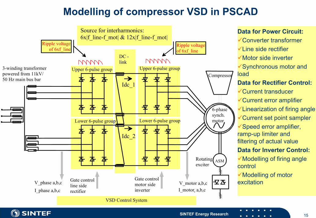
Modelling of compressor VSD in PSCAD
Data for Power Circuit:Converter transformerLine side rectifierMotor side inverterSynchronous motor and
loadData for Rectifier Control:
Current transducerCurrent error amplifierLinearization of firing angleCurrent set point samplerSpeed error amplifier,
ramp-up limiter andfiltering of actual valueData for Inverter Control:
Modelling of firing angle control
Modelling of motor excitation
Ripple voltageof 6xf_line
Idc_1
3-winding transformerpowered from 11kV/50 Hz main bus bar
Gate controlline side rectifier
Upper 6-pulse group
Lower 6-pulse group Lower 6-pulse group
Gate controlmotor side inverter
6-phasesynch.motor
ASM
Ripple voltageof 6xf_line
Upper 6-pulse group
Source for interharmonics:6x|f_line-f_mot| & 12x|f_line-f_mot|
VSD Control System
V_phase a,b,cI_phase a,b,c
V_motor a,b,cI_motorr a,b,c
Compressor
Rotatingexciter
Idc_2
DC -link
16SINTEF Energy Research
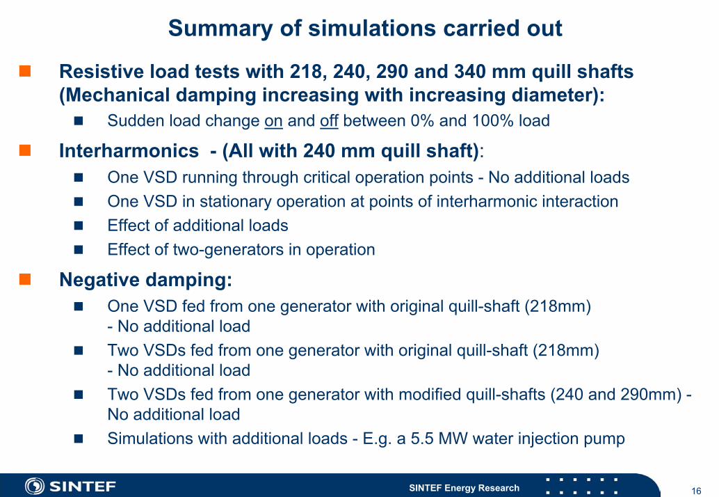
Summary of simulations carried out
Resistive load tests with 218, 240, 290 and 340 mm quill shafts(Mechanical damping increasing with increasing diameter):
Sudden load change on and off between 0% and 100% load
Interharmonics - (All with 240 mm quill shaft):One VSD running through critical operation points - No additional loadsOne VSD in stationary operation at points of interharmonic interactionEffect of additional loadsEffect of two-generators in operation
Negative damping:One VSD fed from one generator with original quill-shaft (218mm)- No additional loadTwo VSDs fed from one generator with original quill-shaft (218mm)- No additional loadTwo VSDs fed from one generator with modified quill-shafts (240 and 290mm) -No additional loadSimulations with additional loads - E.g. a 5.5 MW water injection pump
17SINTEF Energy Research
Simulation of interharmonics
Time (sec)
no name
0 5 10 15 20 25 30 35 40 45 50 +37
+40.4
+43.8
+47.2
+50.6
+54Generator Frequency Motor Frequency
no name
0 5 10 15 20 25 30 35 40 45 50 +8
+13.8
+19.6
+25.4
+31.2
+376xslip 6xsl+3 12xslip 12xsl+6 14.36 Hz
no name
0 5 10 15 20 25 30 35 40 45 50-0.03
+0.026
+0.082
+0.138
+0.194
+0.25TM Te
no name
0 5 10 15 20 25 30 35 40 45 50-0.03
+0.04
+0.11
+0.18
+0.25
+0.32T12
no name
0 5 10 15 20 25 30 35 40 45 50 +0
+0.0176
+0.0352
+0.0528
+0.0704
+0.088TMfund Tefund T12fund
Generator frequencyMotor frequency
54 Hz
Tm, Te
37 Hz
37 Hz
8 Hz
+0.25 pu
-0.03 pu
+0.32 pu
-0.03 pu
+0.088 pu
0 pu
6xslip, 6xslip+3, 12xslip, 12xslip+6, 14.36 Hz
50 sec
T12
Te_fund, T12_fund
Generator frequency
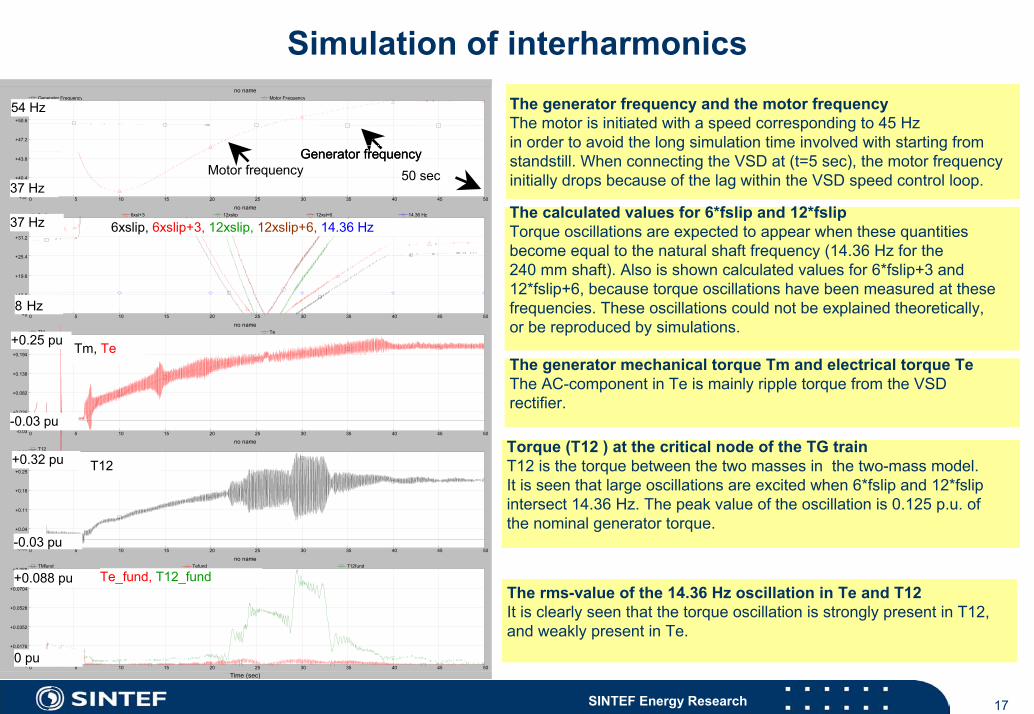
The generator frequency and the motor frequencyThe motor is initiated with a speed corresponding to 45 Hz in order to avoid the long simulation time involved with starting from standstill. When connecting the VSD at (t=5 sec), the motor frequencyinitially drops because of the lag within the VSD speed control loop.
The calculated values for 6*fslip and 12*fslipTorque oscillations are expected to appear when these quantitiesbecome equal to the natural shaft frequency (14.36 Hz for the 240 mm shaft). Also is shown calculated values for 6*fslip+3 and 12*fslip+6, because torque oscillations have been measured at thesefrequencies. These oscillations could not be explained theoretically, or be reproduced by simulations.
The generator mechanical torque Tm and electrical torque TeThe AC-component in Te is mainly ripple torque from the VSDrectifier.
Torque (T12 ) at the critical node of the TG trainT12 is the torque between the two masses in the two-mass model.It is seen that large oscillations are excited when 6*fslip and 12*fslipintersect 14.36 Hz. The peak value of the oscillation is 0.125 p.u. ofthe nominal generator torque.
The rms-value of the 14.36 Hz oscillation in Te and T12 It is clearly seen that the torque oscillation is strongly present in T12, and weakly present in Te.
18SINTEF Energy Research
Frequency analysis of simulated waveforms
6*fslip
12*fslip
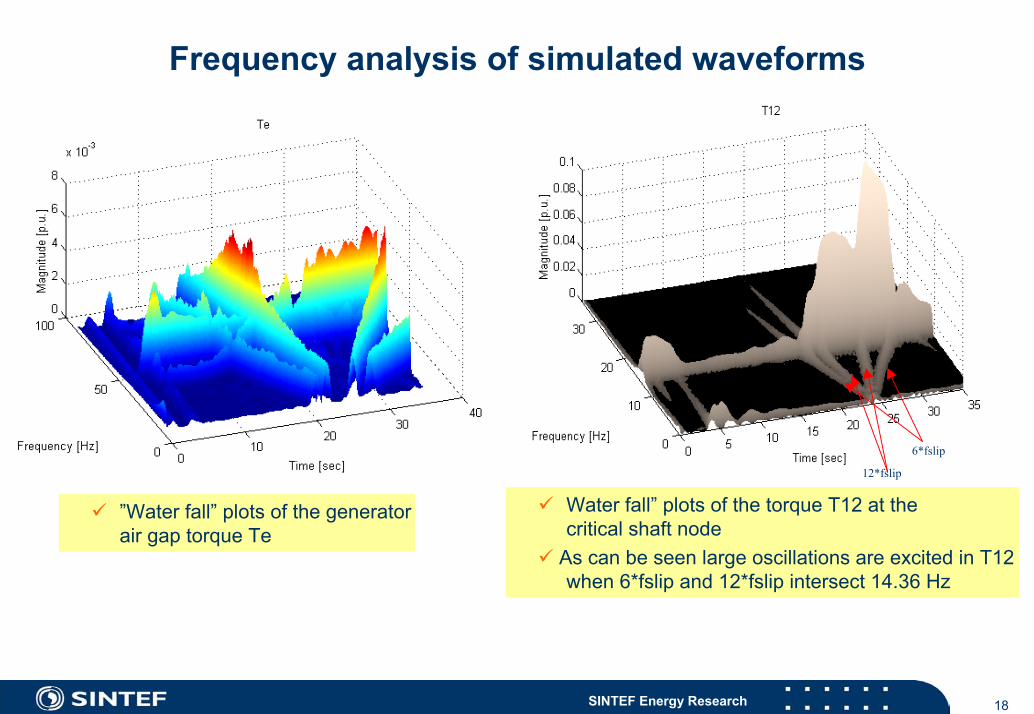
Water fall” plots of the torque T12 at thecritical shaft node
As can be seen large oscillations are excited in T12when 6*fslip and 12*fslip intersect 14.36 Hz
”Water fall” plots of the generatorair gap torque Te
19SINTEF Energy Research
Simulation of negative damping
Time (sec)
no name
0 5 10 15 20 25 30 35 40 45 50 +34
+37.8
+41.6
+45.4
+49.2
+53Generator Frequency Motor Frequency
no name
0 5 10 15 20 25 30 35 40 45 50 +10
+46
+82
+118
+154
+1906xslip 12xslip 14.36 Hz
no name
0 5 10 15 20 25 30 35 40 45 50-0.29
-0.146
-0.002
+0.142
+0.286
+0.43TM Te
no name
0 5 10 15 20 25 30 35 40 45 50 -8
-4.6
-1.2
+2.2
+5.6
+9T12
no name
0 5 10 15 20 25 30 35 40 45 50 +0
+1.1
+2.2
+3.3
+4.4
+5.5TMfund Tefund T12fund
no name
0 5 10 15 20 25 30 35 40 45 50 -5
-1.4
+2.2
+5.8
+9.4
+13 :P_gen
53 Hz
34 Hz
190 Hz
10 Hz
+0.43 pu
-0.29 pu
+9 pu
-8 pu
+5.5 pu
0 pu
+13 MW
-5 MW
Motor frequency
Generator frequency
6xslip, 12xslip, 12.5 Hz
Tm, Te
50 sec
T12
T12_fund
P_gen
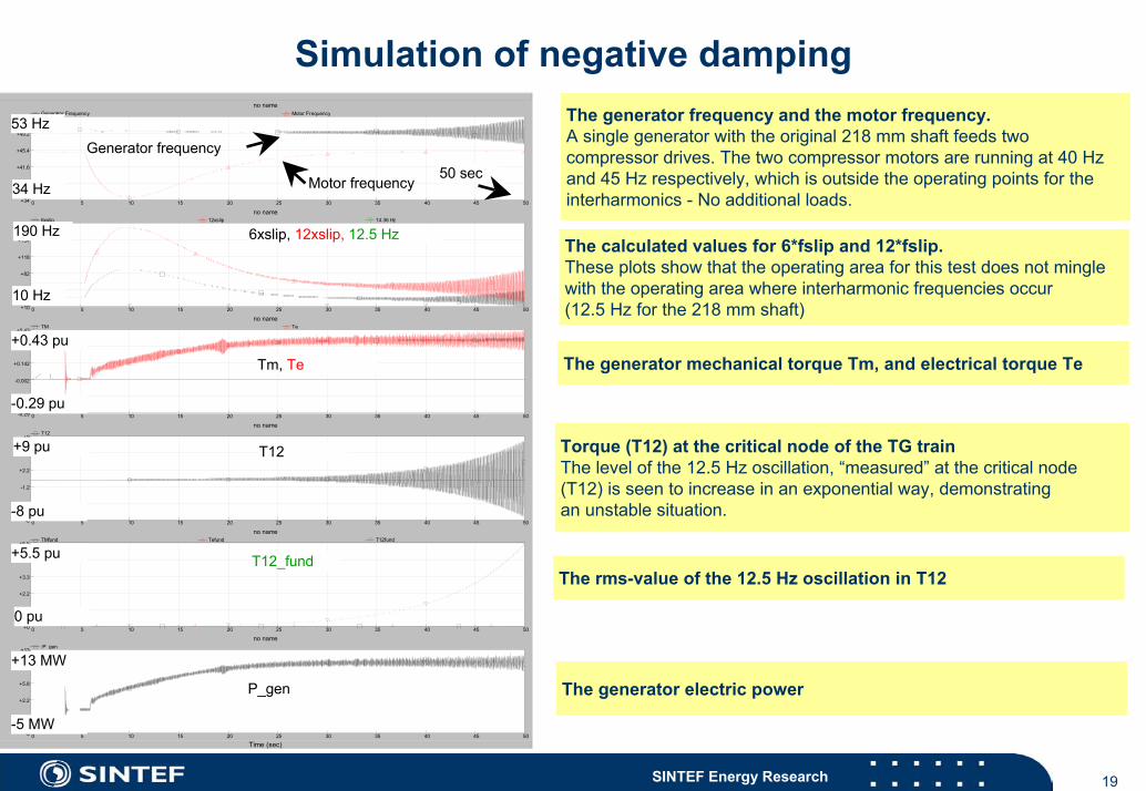
The generator frequency and the motor frequency. A single generator with the original 218 mm shaft feeds two compressor drives. The two compressor motors are running at 40 Hzand 45 Hz respectively, which is outside the operating points for theinterharmonics - No additional loads.
The calculated values for 6*fslip and 12*fslip.These plots show that the operating area for this test does not minglewith the operating area where interharmonic frequencies occur(12.5 Hz for the 218 mm shaft)
The generator mechanical torque Tm, and electrical torque Te
Torque (T12) at the critical node of the TG trainThe level of the 12.5 Hz oscillation, “measured” at the critical node (T12) is seen to increase in an exponential way, demonstrating an unstable situation.
The rms-value of the 12.5 Hz oscillation in T12
The generator electric power
20SINTEF Energy Research
ConclusionsBoth the interaction mechanisms described initially in the presentation have been identified and demonstrated by simulations with PSCAD/EMTDC. The source for the interharmonic interaction was found to be frequency components in the DC-link currents of the compressor VSDs, generated by the difference between line side and motor side fundamental frequencyThe torsional oscillation level may reach 0.24 p.u. peak-peak with modified 240mm quill shaft, when the compressor VSDs are allowed to run through critical operation points with their maximum slew rateIf the VSDs are allowed to stay at critical speeds, torsional oscillations of 2.5 peak-peak of nominal generator torque have been simulated. It should be noted that this is theoretical values applicable for a linear systemExperience after installation of the 240 mm modified shaft confirms that the vibration level is still to highThe control system for the compressor VSDs seems to be passive to the interharmonic oscillationsNeither the turbine governor, nor the exciter control system seem to interfere with the oscillations introduced by interharmonics
21SINTEF Energy Research
Conclusions cont.
Exponential increasing generator shaft oscillations as result of negative damping have been demonstrated, when simulating a situation where one generator powers both compressor drives. The original 218 mm shaft was definitively unstable, while the modified 240 mm shaft could become unstable during worst case conditions The positive effect of further additional mechanical damping by increasing the diameter of the quill shaft to 290 mm, was clearly demonstratedThe stabilizing effect of additional resistive load in the power grid was demonstrated for both original and modified shaftsPositive damping effect from the direct line driven 5.5 MW water injection pump was demonstrated for modified shafts, while the original shaft shows to be unstableTime domain simulations applying tools like PSCAD/EMTDC have proved to be a very valuable tool to clarify possible interaction problems in power grids where power electronic converters are involved, provided sufficient detailed modelling, and provided that sufficient data is obtainable from the vendorsAs result from this simulation study a new quill shaft with 290 mm diameter has been installed

22SINTEF Energy Research
Approximations and uncertainties
The approximations of most concern as regards influence on simulation results are:
Uncertain data for TG train shaft dynamics. Especially data for mechanical dampingLack of data for dynamics for the synchronization of control angles for the VSD rectifier and inverterLack of data for dynamics of the compressor load-torque characteristicsLack of data for dynamics of the compressor motor excitation controller
23SINTEF Energy Research
Other countermeasures than replacing quill shaft ?
Other, ”more elegant” countermeasures than increasing the damping by replacing the quill shaft has been considered, but have so far not been detailed investigated.
Investigate the possibility for introducing active damping at the lowest natural frequency of the TG train by modifications of the generator exciter controllerInvestigate possible modifications of the control system of the compressor driveVSDsEvaluate a dedicated active DC-type filter or attenuator in the DC-link of theVSDs, tuned to the critical generator shaft frequencyEvaluate an active AC-type filter or attenuator in the 11kV network, directly, or preferably via transformer. Such device could also be configured to take care of other possible interaction sources in the platform power grid
24SINTEF Energy Research
References
Clarification of possible network interaction between turbine-generator train and converters in the power network at VISUND – Accomplished project for Norsk Hydro
• Technical report: TR F5451• ”Investigation of Possible Network Interaction between Turbine-Generator Trains and
Converters in the Power Grid at the Oil Platform Visund” - Paper presented on PCC-Osaka 2002:
"Clarification of possible interactions between generator train and converter at GRANE” – Accomplished project for Kvaerner Oil and Gas
• Technical report TR F5477Simulation of possible VSD and Gas Turbine-Generator interaction at the HAMMERFEST LNG-plant – Pågående prosjekt for Linde AG
• A project in cooperation with: Ødegaard & Danneskiold-Samsøe A/S (ØDS)
• 5 generators with detailed modelling of electrical and mechanical dynamics
• 4 large compressor drives with detailed modelling of electrical and mechanical dynamics
• Underlying grid with i.a. several direct coupled asynchronous motors
• Cables and lines to external grid (Hammerfest, Skaidi)