Embed Size (px)
Citation preview
International Journal of Science and Research (IJSR) ISSN (Online): 2319-7064
Impact Factor (2012): 3.358
Volume 3 Issue 12, December 2014 www.ijsr.net
Licensed Under Creative Commons Attribution CC BY
Risk Reduction of SSO and Enhance the Stability in DFIG Control Systems Using Multi-Input Multi-
Output State Space Methodology
G. Rajeswari1, A. Anuradha2
1PG Student, Valliammai Engineering College, Chennai, India.
, 2Assistant Professor, Valliammai Engineering College, Chennai, India.
Abstract: Doubly-fed induction generators (DFIGs) have gained widespread acceptance in modern wind energy conversion systems. The stability and dynamics of power systems involving DFIGs have recently become salient issues. With the use of high power voltage source converters (VSCs)-based DFIG wind farms connected to series capacitors, sub-synchronous dynamics usually exist which reduces the overall damping and results in unstable dynamics. This paper investigates the sub-synchronous interactions (SSIs) by using eigenvalues and modal analysis tools, proposes sub-synchronous damping controller, which is integrated to the grid side converter as well as rotor side converter. Furthermore, this SSI damping controls are designed using multi-input multi-output (MIMO) approach. This provides greater flexibility in using several measurements and control inputs. Thus, this robust technique is able to properly damp the sub-synchronous resonance in a power system with series-compensated line. Keywords: SSI mitigation, series compensation, sub-synchronous control interactions (SSCI), sub-synchronous resonance (SSR), wind energy conversion systems (WECS). 1. Introduction
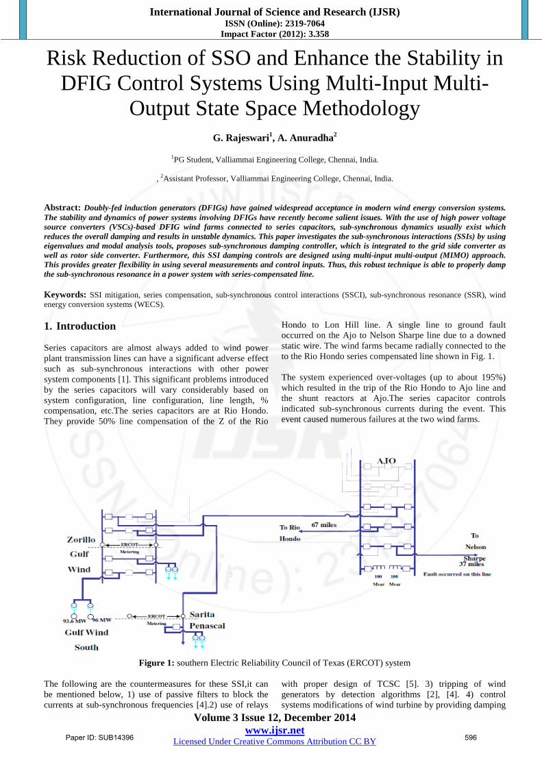
Series capacitors are almost always added to wind power plant transmission lines can have a significant adverse effect such as sub-synchronous interactions with other power system components [1]. This significant problems introduced by the series capacitors will vary considerably based on system configuration, line configuration, line length, % compensation, etc.The series capacitors are at Rio Hondo. They provide 50% line compensation of the Z of the Rio
Hondo to Lon Hill line. A single line to ground fault occurred on the Ajo to Nelson Sharpe line due to a downed static wire. The wind farms became radially connected to the to the Rio Hondo series compensated line shown in Fig. 1. The system experienced over-voltages (up to about 195%) which resulted in the trip of the Rio Hondo to Ajo line and the shunt reactors at Ajo.The series capacitor controls indicated sub-synchronous currents during the event. This event caused numerous failures at the two wind farms.
Figure 1: southern Electric Reliability Council of Texas (ERCOT) system
The following are the countermeasures for these SSI,it can be mentioned below, 1) use of passive filters to block the currents at sub-synchronous frequencies [4].2) use of relays
with proper design of TCSC [5]. 3) tripping of wind generators by detection algorithms [2], [4]. 4) control systems modifications of wind turbine by providing damping
Paper ID: SUB14396 596
International Journal of Science and Research (IJSR) ISSN (Online): 2319-7064
Impact Factor (2012): 3.358
Volume 3 Issue 12, December 2014 www.ijsr.net
Licensed Under Creative Commons Attribution CC BY
controls to damp the SSR frequencies [2], [4], [11] and [12]. The last solution avoids the implementation of expensive additional damping devices, such as FACTS or bypass filters. Thus this solution is very economic [6], [7]. This paper addresses the last solution in which two approaches can be implemented for DFIG wind turbines: one of them adds an SSI damping control signal in the reactive current control loop of the grid-side converter (GSC) [2], whereas the other one adds the damping control signal in the rotor voltage through the rotor-side converter (RSC) [11], [12]. Additionally, comparison of the GSC and RSC control loops to perform SSI damping action effectively. In this way, it could be more acceptable for system operators and manufactures who are usually conservative to fully replace the well-known PI control structures. 2. Stability Analysis Small signal stability is defined as the ability of a power system to return to a stable operating point, after any disturbance that leads to an incremental change in one or more of the state variables of the power system [1]. In this work, the small signal stability problems for wind power generation will be researched and how they impact on a power system. All this work begins on the space equation and the output equation which give the necessary information.
x(t) = f (x, u, t)
y(t) = g (x, u, t) (1)
Where, equation (1) has all state variables, u is the input variables, t is time and y is the output function. The linearization of equation(1) allows investigating the response to small variations. To do this, and considering that state functions contains some different variables on its polynomial equation, these equations are developed in Taylor´s series expansion in which with higher orders of the derivatives omitted because of its minimum interaction to the response. The linear result is a system presented in equation
x = Ax + Bu
y = cx(2)
Where A is the state matrix, B is the input matrix, c the output matrix. Finally to obtain the eigenvalues it must be found the values of s that satisfy [5],Det(sI-A)=0. The n-solutions of λ = λ1 , λ2 , … λn are the eigenvalues of A. These eigenvalues can be real or complex [2]. In this paper, PSAT software [18], (Fig.1), is used to analysis the eigenvalues. Roots positions and its values as they appear on this plot show if system is stable or not. As can be seen all real values are negatives which means system is stable under this conditions. The full eigenvalues report shows results in matrix and also participation factors are presented.
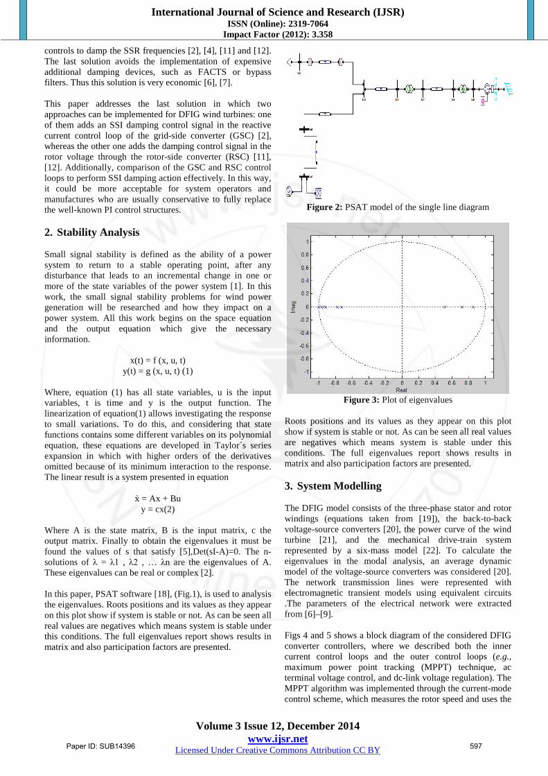
Figure 2: PSAT model of the single line diagram
Figure 3: Plot of eigenvalues
Roots positions and its values as they appear on this plot show if system is stable or not. As can be seen all real values are negatives which means system is stable under this conditions. The full eigenvalues report shows results in matrix and also participation factors are presented. 3. System Modelling The DFIG model consists of the three-phase stator and rotor windings (equations taken from [19]), the back-to-back voltage-source converters [20], the power curve of the wind turbine [21], and the mechanical drive-train system represented by a six-mass model [22]. To calculate the eigenvalues in the modal analysis, an average dynamic model of the voltage-source converters was considered [20]. The network transmission lines were represented with electromagnetic transient models using equivalent circuits .The parameters of the electrical network were extracted from [6]–[9]. Figs 4 and 5 shows a block diagram of the considered DFIG converter controllers, where we described both the inner current control loops and the outer control loops (e.g., maximum power point tracking (MPPT) technique, ac terminal voltage control, and dc-link voltage regulation). The MPPT algorithm was implemented through the current-mode control scheme, which measures the rotor speed and uses the
Paper ID: SUB14396 597
International Journal of Science and Research (IJSR) ISSN (Online): 2319-7064
Impact Factor (2012): 3.358
Volume 3 Issue 12, December 2014 www.ijsr.net
Licensed Under Creative Commons Attribution CC BY
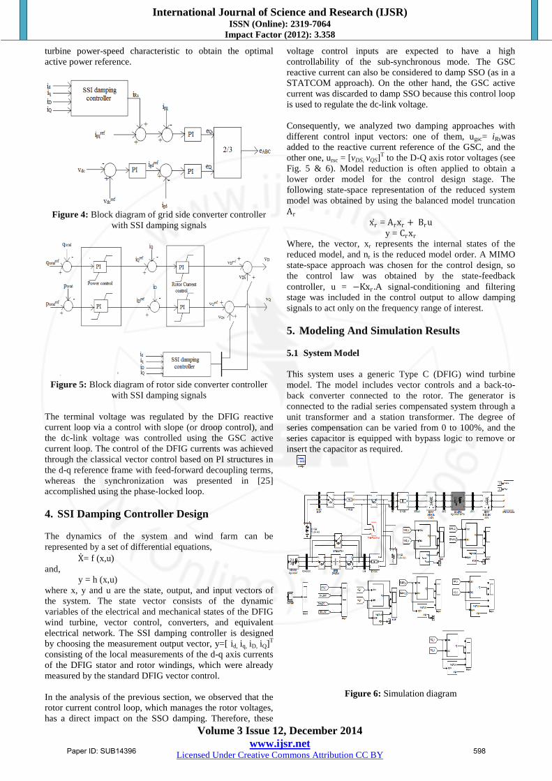
turbine power-speed characteristic to obtain the optimal active power reference.
Figure 4: Block diagram of grid side converter controller
with SSI damping signals
Figure 5: Block diagram of rotor side converter controller
with SSI damping signals The terminal voltage was regulated by the DFIG reactive current loop via a control with slope (or droop control), and the dc-link voltage was controlled using the GSC active current loop. The control of the DFIG currents was achieved through the classical vector control based on PI structures in the d-q reference frame with feed-forward decoupling terms, whereas the synchronization was presented in [25] accomplished using the phase-locked loop. 4. SSI Damping Controller Design The dynamics of the system and wind farm can be represented by a set of differential equations,
X= f (x,u) and,
y = h (x,u) where x, y and u are the state, output, and input vectors of the system. The state vector consists of the dynamic variables of the electrical and mechanical states of the DFIG wind turbine, vector control, converters, and equivalent electrical network. The SSI damping controller is designed by choosing the measurement output vector, y=[ id, iq, iD, iQ]T consisting of the local measurements of the d-q axis currents of the DFIG stator and rotor windings, which were already measured by the standard DFIG vector control. In the analysis of the previous section, we observed that the rotor current control loop, which manages the rotor voltages, has a direct impact on the SSO damping. Therefore, these
voltage control inputs are expected to have a high controllability of the sub-synchronous mode. The GSC reactive current can also be considered to damp SSO (as in a STATCOM approach). On the other hand, the GSC active current was discarded to damp SSO because this control loop is used to regulate the dc-link voltage. Consequently, we analyzed two damping approaches with different control input vectors: one of them, ugsc= iRswas added to the reactive current reference of the GSC, and the other one, ursc = [vDS, vQS]T to the D-Q axis rotor voltages (see Fig. 5 & 6). Model reduction is often applied to obtain a lower order model for the control design stage. The following state-space representation of the reduced system model was obtained by using the balanced model truncation Ar
xr = Arxr + Bru y = Crxr
Where, the vector, xr represents the internal states of the reduced model, and nr is the reduced model order. A MIMO state-space approach was chosen for the control design, so the control law was obtained by the state-feedback controller, u = −Kxr .A signal-conditioning and filtering stage was included in the control output to allow damping signals to act only on the frequency range of interest. 5. Modeling And Simulation Results
5.1 System Model This system uses a generic Type C (DFIG) wind turbine model. The model includes vector controls and a back-to-back converter connected to the rotor. The generator is connected to the radial series compensated system through a unit transformer and a station transformer. The degree of series compensation can be varied from 0 to 100%, and the series capacitor is equipped with bypass logic to remove or insert the capacitor as required.
Figure 6: Simulation diagram
Paper ID: SUB14396 598
International Journal of Science and Research (IJSR) ISSN (Online): 2319-7064
Impact Factor (2012): 3.358
Volume 3 Issue 12, December 2014 www.ijsr.net
Licensed Under Creative Commons Attribution CC BY
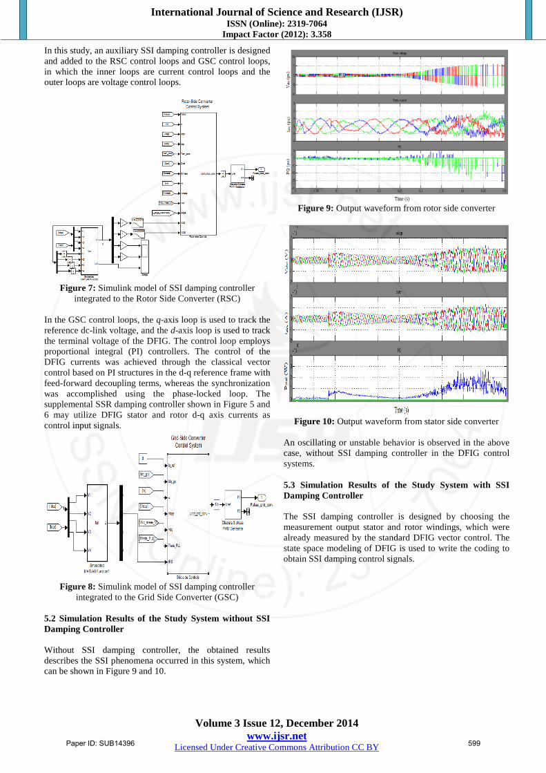
In this study, an auxiliary SSI damping controller is designed and added to the RSC control loops and GSC control loops, in which the inner loops are current control loops and the outer loops are voltage control loops.
Figure 7: Simulink model of SSI damping controller
integrated to the Rotor Side Converter (RSC) In the GSC control loops, the q-axis loop is used to track the reference dc-link voltage, and the d-axis loop is used to track the terminal voltage of the DFIG. The control loop employs proportional integral (PI) controllers. The control of the DFIG currents was achieved through the classical vector control based on PI structures in the d-q reference frame with feed-forward decoupling terms, whereas the synchronization was accomplished using the phase-locked loop. The supplemental SSR damping controller shown in Figure 5 and 6 may utilize DFIG stator and rotor d-q axis currents as control input signals.
Figure 8: Simulink model of SSI damping controller
integrated to the Grid Side Converter (GSC) 5.2 Simulation Results of the Study System without SSI Damping Controller Without SSI damping controller, the obtained results describes the SSI phenomena occurred in this system, which can be shown in Figure 9 and 10.
Figure 9: Output waveform from rotor side converter
Figure 10: Output waveform from stator side converter
An oscillating or unstable behavior is observed in the above case, without SSI damping controller in the DFIG control systems. 5.3 Simulation Results of the Study System with SSI Damping Controller The SSI damping controller is designed by choosing the measurement output stator and rotor windings, which were already measured by the standard DFIG vector control. The state space modeling of DFIG is used to write the coding to obtain SSI damping control signals.
Paper ID: SUB14396 599
International Journal of Science and Research (IJSR) ISSN (Online): 2319-7064
Impact Factor (2012): 3.358
Volume 3 Issue 12, December 2014 www.ijsr.net
Licensed Under Creative Commons Attribution CC BY
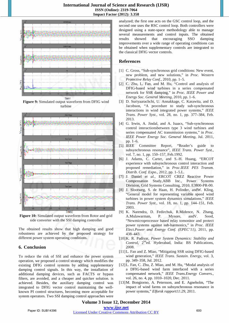
Figure 9: Simulated output waveform from DFIG wind
turbine
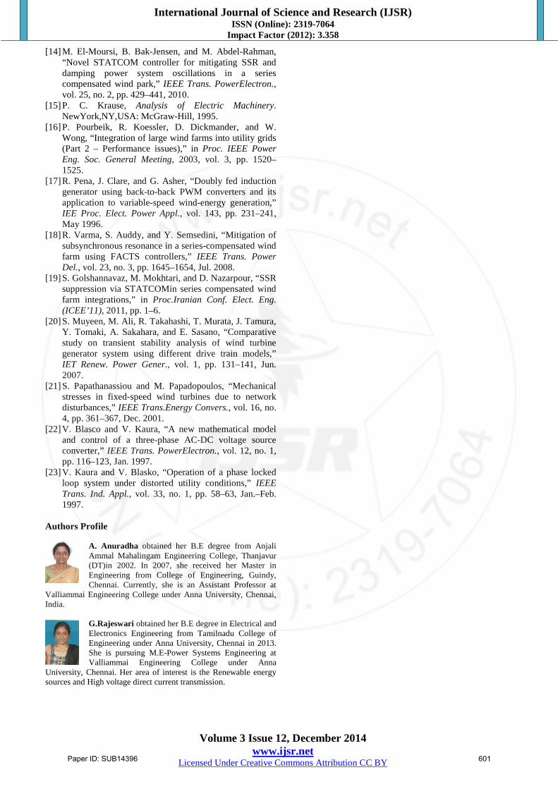
Figure 10: Simulated output waveform from Rotor and grid
side converter with the SSI damping controller The obtained results show that high damping and good robustness are achieved by the proposed strategy for different power system operating conditions. 6. Conclusion To reduce the risk of SSI and enhance the power system operation, we proposed a control strategy which modifies the existing DFIG control systems by adding supplementary damping control signals. In this way, the installation of additional damping devices, such as FACTS or bypass filters, are avoided, and a cheaper and quicker solution. is achieved. Besides, the auxiliary damping control was integrated to DFIG vector control maintaining the well-known PI control structures, becoming more acceptable for system operators. Two SSI damping control approaches were
analyzed; the first one acts on the GSC control loop, and the second one uses the RSC control loop. Both controllers were designed using a state-space methodology able to manage several measurements and control inputs. The obtained results showed that encouraging SSO damping improvements over a wide range of operating conditions can be obtained when supplementary controls are integrated to the classical DFIG vector controls. References [1] C. Gross, “Sub-synchronous grid conditions: New event,
new problem, and new solutions,” in Proc. Western Protective Relay Conf., 2010, pp. 1–5.
[2] C. Zhu, L. Fan, and M. Hu, “Control and analysis of DFIG-based wind turbines in a series compensated network for SSR damping,” in Proc. IEEE Power and Energy Soc. General Meeting, 2010, pp. 1–6.
[3] D. Suriyaarachchi, U. Annakkage, C. Karawita, and D. Jacobson, “A procedure to study sub-synchronous interactions in wind integrated power systems,” IEEE Trans. Power Syst., vol. 28, no. 1, pp. 377–384, Feb. 2013.
[4] G. Irwin, A. Jindal, and A. Isaacs, “Sub-synchronous control interactionsbetween type 3 wind turbines and series compensated AC transmission systems,” in Proc. IEEE Power Energy Soc. General Meeting, Jul. 2011, pp. 1–6.
[5] IEEE Committee Report, “Reader’s guide to subsynchronous resonance”, IEEE Trans. Power Syst., vol. 7, no. 1, pp. 150–157, Feb.1992.
[6] J. Adams, C. Carter, and S.-H. Huang, “ERCOT experience with subsynchronous control interaction and proposed remediation,” in Proc.IEEE PES Transm. Distrib. Conf. Expo., 2012, pp. 1–5.L.
[7] J. Daniel et al., ERCOT CREZ Reactive Power Compensation Study,ABB Inc., Power Systems Division, Grid Systems Consulting, 2010, E3800-PR-00.
[8] J. Slootweg, S. de Haan, H. Polinder, andW. Kling, “General model for representing variable speed wind turbines in power system dynamics simulations,” IEEE Trans. Power Syst., vol. 18, no. 1, pp. 144–151, Feb. 2003.
[9] K. Narendra, D. Fedirchuk, R.Midence, N. Zhang, A.Mulawarman, P. Mysore, andV. Sood, “Newmicroprocessor based relay tomonitor and protect power systems against sub-harmonics,” in Proc. IEEE Elect.Power and Energy Conf. (EPEC’11), 2011, pp. 438–443.
[10] K. R. Padiyar, Power System Dynamics: Stability and Control, 2nded. Hyderabad, India: BS Publications, 2008.
[11] L. Fan and Z. Miao, “Mitigating SSR using DFIG-based wind generation,” IEEE Trans. Sustain. Energy, vol. 3, pp. 349–358, Jul. 2012.
[12] L. Fan, C. Zhu, Z. Miao, and M. Hu, “Modal analysis of a DFIG-based wind farm interfaced with a series compensated network,” IEEE Trans.Energy Convers., vol. 26, no. 4, pp. 1010–1020, Dec. 2011.
[13] M. Bongiorno, A. Petersson, and E. Agneholm, “The impact of wind farms on subsynchronous resonance in power systems,” Elforsk rapport11:29, 2011.
Paper ID: SUB14396 600
International Journal of Science and Research (IJSR) ISSN (Online): 2319-7064
Impact Factor (2012): 3.358
Volume 3 Issue 12, December 2014 www.ijsr.net
Licensed Under Creative Commons Attribution CC BY
[14] M. El-Moursi, B. Bak-Jensen, and M. Abdel-Rahman, “Novel STATCOM controller for mitigating SSR and damping power system oscillations in a series compensated wind park,” IEEE Trans. PowerElectron., vol. 25, no. 2, pp. 429–441, 2010.
[15] P. C. Krause, Analysis of Electric Machinery. NewYork,NY,USA: McGraw-Hill, 1995.
[16] P. Pourbeik, R. Koessler, D. Dickmander, and W. Wong, “Integration of large wind farms into utility grids (Part 2 – Performance issues),” in Proc. IEEE Power Eng. Soc. General Meeting, 2003, vol. 3, pp. 1520–1525.
[17] R. Pena, J. Clare, and G. Asher, “Doubly fed induction generator using back-to-back PWM converters and its application to variable-speed wind-energy generation,” IEE Proc. Elect. Power Appl., vol. 143, pp. 231–241, May 1996.
[18] R. Varma, S. Auddy, and Y. Semsedini, “Mitigation of subsynchronous resonance in a series-compensated wind farm using FACTS controllers,” IEEE Trans. Power Del., vol. 23, no. 3, pp. 1645–1654, Jul. 2008.
[19] S. Golshannavaz, M. Mokhtari, and D. Nazarpour, “SSR suppression via STATCOMin series compensated wind farm integrations,” in Proc.Iranian Conf. Elect. Eng. (ICEE’11), 2011, pp. 1–6.
[20] S. Muyeen, M. Ali, R. Takahashi, T. Murata, J. Tamura, Y. Tomaki, A. Sakahara, and E. Sasano, “Comparative study on transient stability analysis of wind turbine generator system using different drive train models,” IET Renew. Power Gener., vol. 1, pp. 131–141, Jun. 2007.
[21] S. Papathanassiou and M. Papadopoulos, “Mechanical stresses in fixed-speed wind turbines due to network disturbances,” IEEE Trans.Energy Convers., vol. 16, no. 4, pp. 361–367, Dec. 2001.
[22] V. Blasco and V. Kaura, “A new mathematical model and control of a three-phase AC-DC voltage source converter,” IEEE Trans. PowerElectron., vol. 12, no. 1, pp. 116–123, Jan. 1997.
[23] V. Kaura and V. Blasko, “Operation of a phase locked loop system under distorted utility conditions,” IEEE Trans. Ind. Appl., vol. 33, no. 1, pp. 58–63, Jan.–Feb. 1997.
Authors Profile
A. Anuradha obtained her B.E degree from Anjali Ammal Mahalingam Engineering College, Thanjavur (DT)in 2002. In 2007, she received her Master in Engineering from College of Engineering, Guindy, Chennai. Currently, she is an Assistant Professor at
Valliammai Engineering College under Anna University, Chennai, India.
G.Rajeswari obtained her B.E degree in Electrical and Electronics Engineering from Tamilnadu College of Engineering under Anna University, Chennai in 2013. She is pursuing M.E-Power Systems Engineering at Valliammai Engineering College under Anna
University, Chennai. Her area of interest is the Renewable energy sources and High voltage direct current transmission.
Paper ID: SUB14396 601