Embed Size (px)
Citation preview
RIT Senior Design Project 10662D3 Engineering Camera Platform
Friday October 9, 2009 11:30 to 1:00pm

Team Members
• Gregory Hintz (EE)• Samuel Skalicky (CE)• Jeremy Greene (EE)• Jared Burdick (EE)• Michelle Bard (ME)• Anthony Perrone (ME)
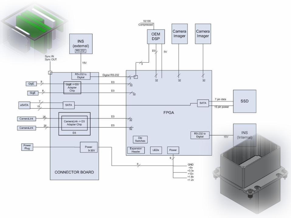
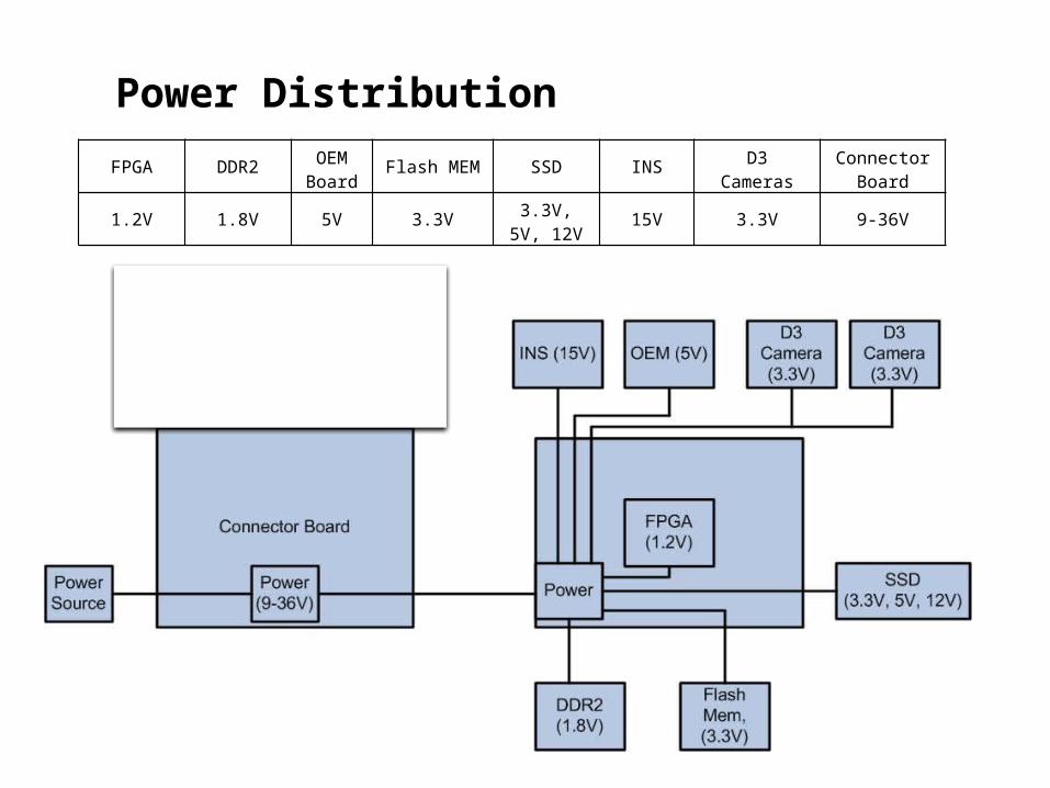
Power Distribution
FPGA DDR2OEM Board
Flash MEM SSD INS D3 CamerasConnector
Board
1.2V 1.8V 5V 3.3V3.3V, 5V,
12V15V 3.3V 9-36V
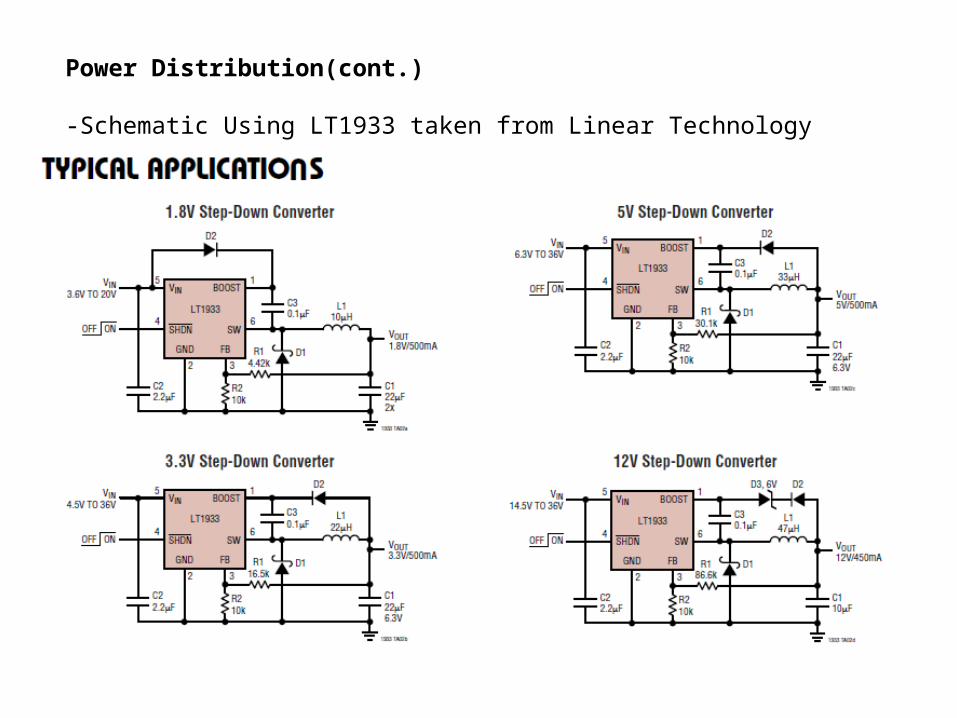
Power Distribution(cont.)
-Schematic Using LT1933 taken from Linear Technology
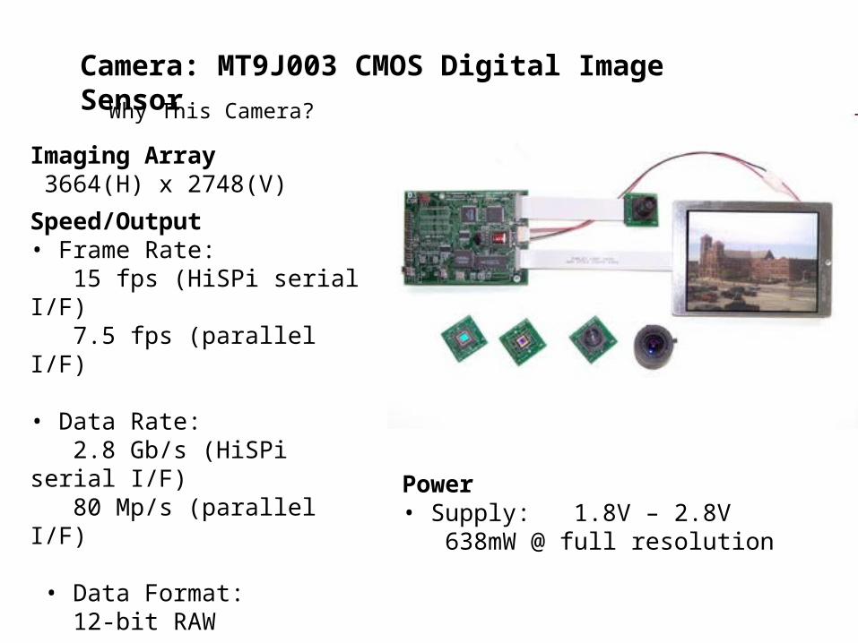
Camera: MT9J003 CMOS Digital Image SensorWhy This Camera?
Imaging Array 3664(H) x 2748(V)
Speed/Output• Frame Rate:
15 fps (HiSPi serial I/F) 7.5 fps (parallel I/F)
• Data Rate: 2.8 Gb/s (HiSPi serial I/F) 80 Mp/s (parallel I/F)
• Data Format: 12-bit RAW
Temperature Range• –30°C to +70°C
Power• Supply: 1.8V – 2.8V
638mW @ full resolution

Interfaces
D3 Camera Interface-16-bit parallel output-6 Miscellaneous positions-Two wire I²C bus interface-Several clock and control positions
CameraLink -LVDS to achieve theoretical transmission
rate of 1.923Gbps-Not dependent on a particular supply
voltage because of low signal voltage swing
GigE-High bandwidth for high-speed, and high
resolution cameras-Downward compatible with 10/100 Mhz
Ethernet-Operates at a fast frame rate
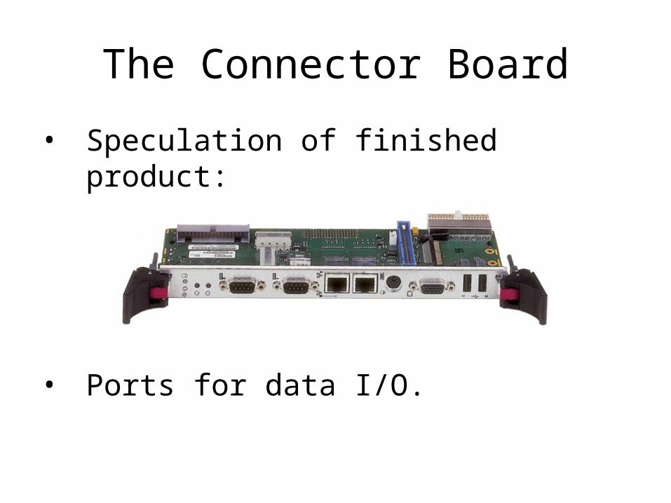
The Connector Board
• Speculation of finished product:
• Ports for data I/O.
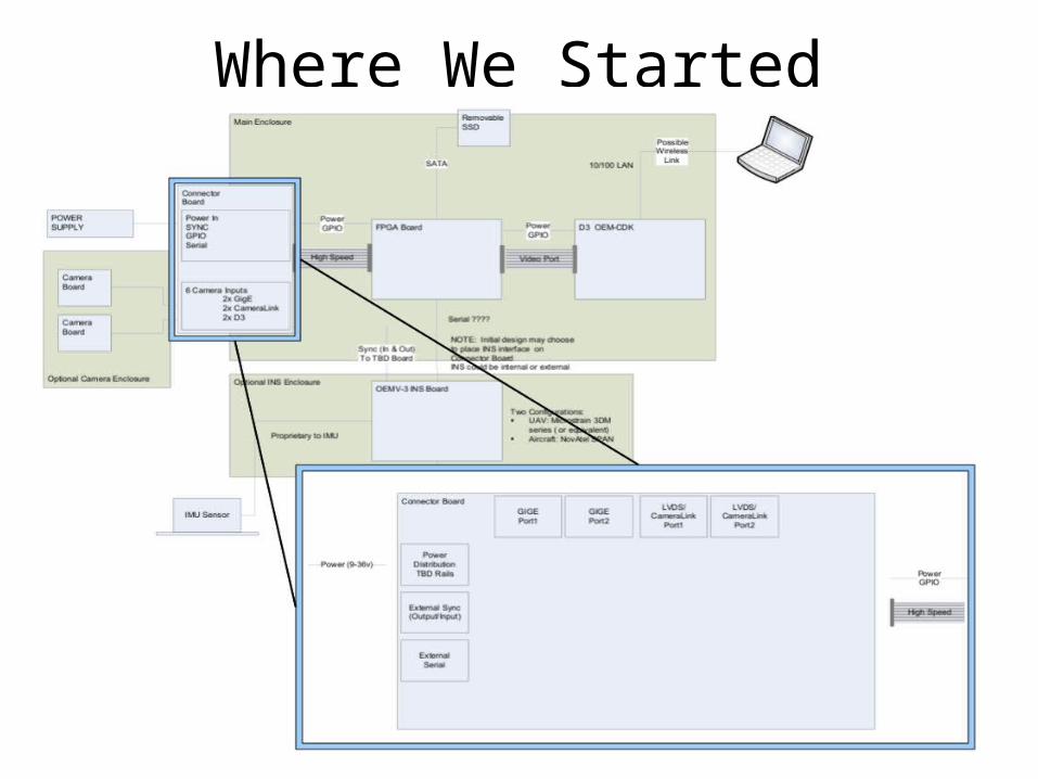
Where We Started
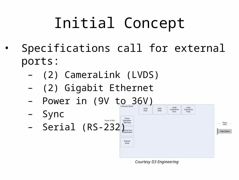
Initial Concept
• Specifications call for external ports:– (2) CameraLink (LVDS)– (2) Gigabit Ethernet– Power in (9V to 36V)– Sync– Serial (RS-232)
Courtesy D3 Engineering
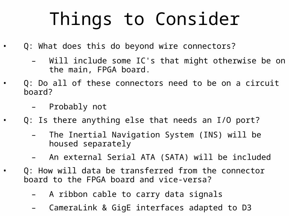
Things to Consider• Q: What does this do beyond wire connectors?
– Will include some IC's that might otherwise be on the main, FPGA board.
• Q: Do all of these connectors need to be on a circuit board?
– Probably not
• Q: Is there anything else that needs an I/O port?
– The Inertial Navigation System (INS) will be housed separately
– An external Serial ATA (SATA) will be included
• Q: How will data be transferred from the connector board to the FPGA board and vice-versa?
– A ribbon cable to carry data signals
– CameraLink & GigE interfaces adapted to D3
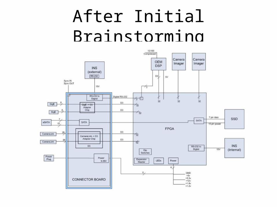
After Initial Brainstorming
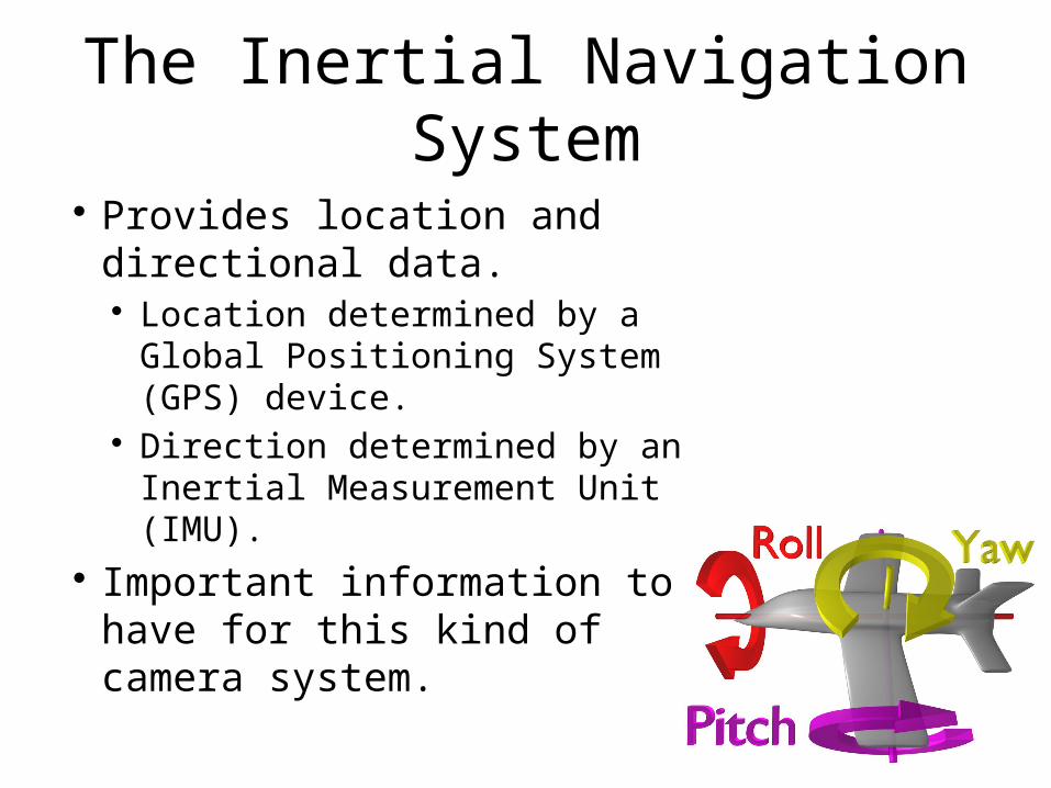
The Inertial Navigation System
Provides location and directional data. Location determined by a Global
Positioning System (GPS) device. Direction determined by an
Inertial Measurement Unit (IMU). Important information to have
for this kind of camera system.

Considering the Options
MicroStrain 3DM
Both can be used with RS232 port.
NovAtel SPAN

Enclosure Consideration
Some models contain the GPS and IMU in a single unit, others separate them.
May have noteworthy impact on size and design of the system enclosure.
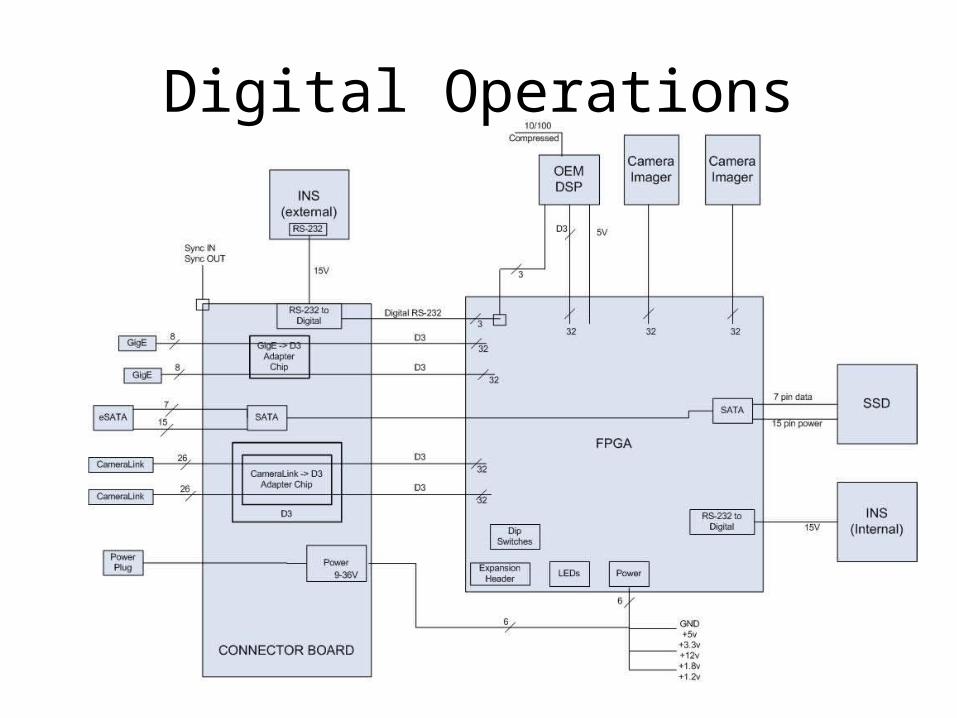
Digital Operations
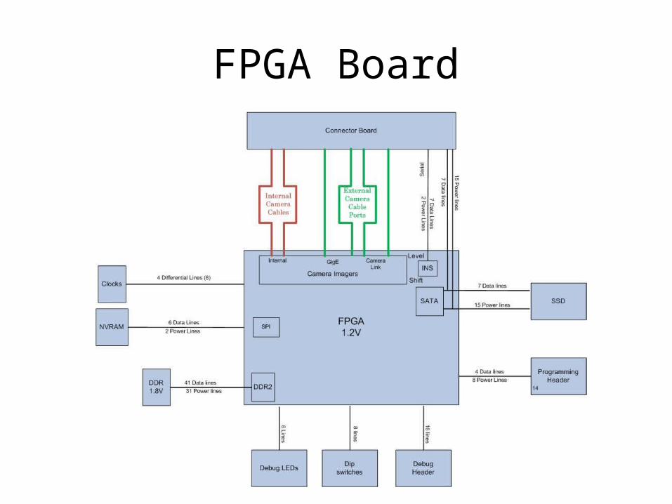
FPGA Board
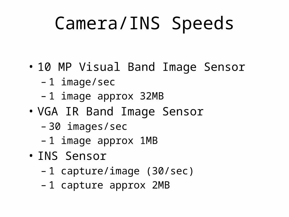
Camera/INS Speeds
• 10 MP Visual Band Image Sensor– 1 image/sec– 1 image approx 32MB
• VGA IR Band Image Sensor– 30 images/sec– 1 image approx 1MB
• INS Sensor– 1 capture/image (30/sec)– 1 capture approx 2MB
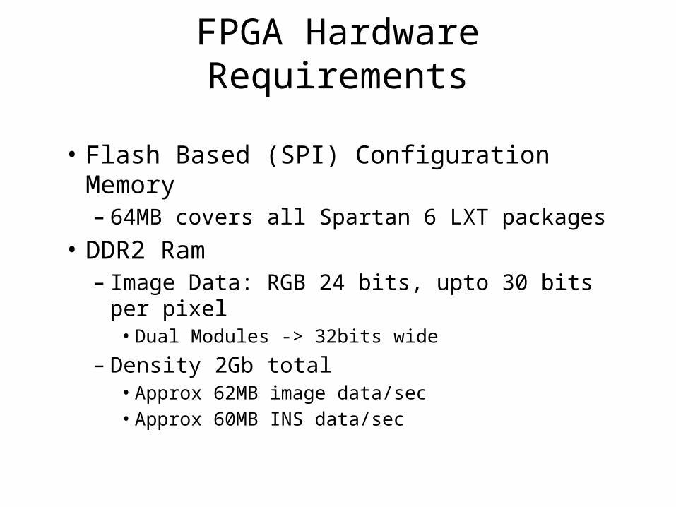
FPGA Hardware Requirements
• Flash Based (SPI) Configuration Memory– 64MB covers all Spartan 6 LXT packages
• DDR2 Ram– Image Data: RGB 24 bits, upto 30 bits per
pixel• Dual Modules -> 32bits wide
– Density 2Gb total• Approx 62MB image data/sec• Approx 60MB INS data/sec
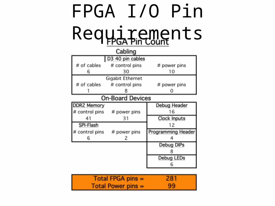
FPGA I/O Pin Requirements
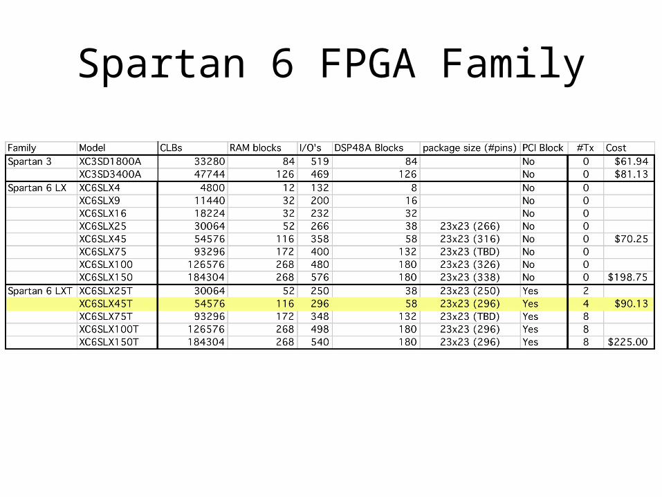
Spartan 6 FPGA Family
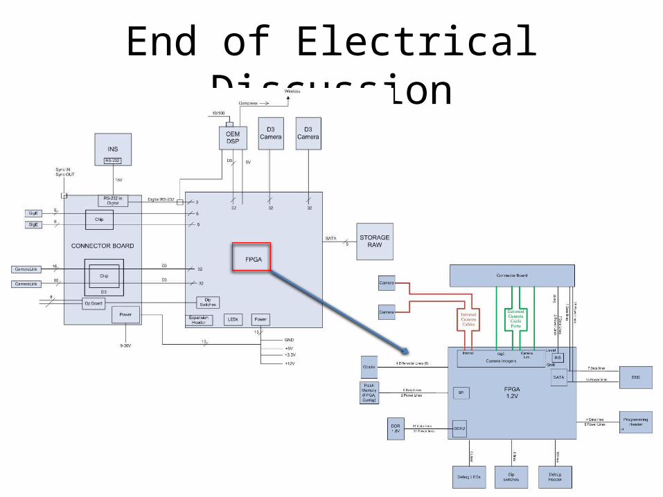
End of Electrical Discussion
Needs Considerations Approach
• Maintain optimal temperature range required by components
• Prevent the heat produced by the electronics from interfering with the operation of cameras
• Maintain an air/water tight environment
Heat Mitigation
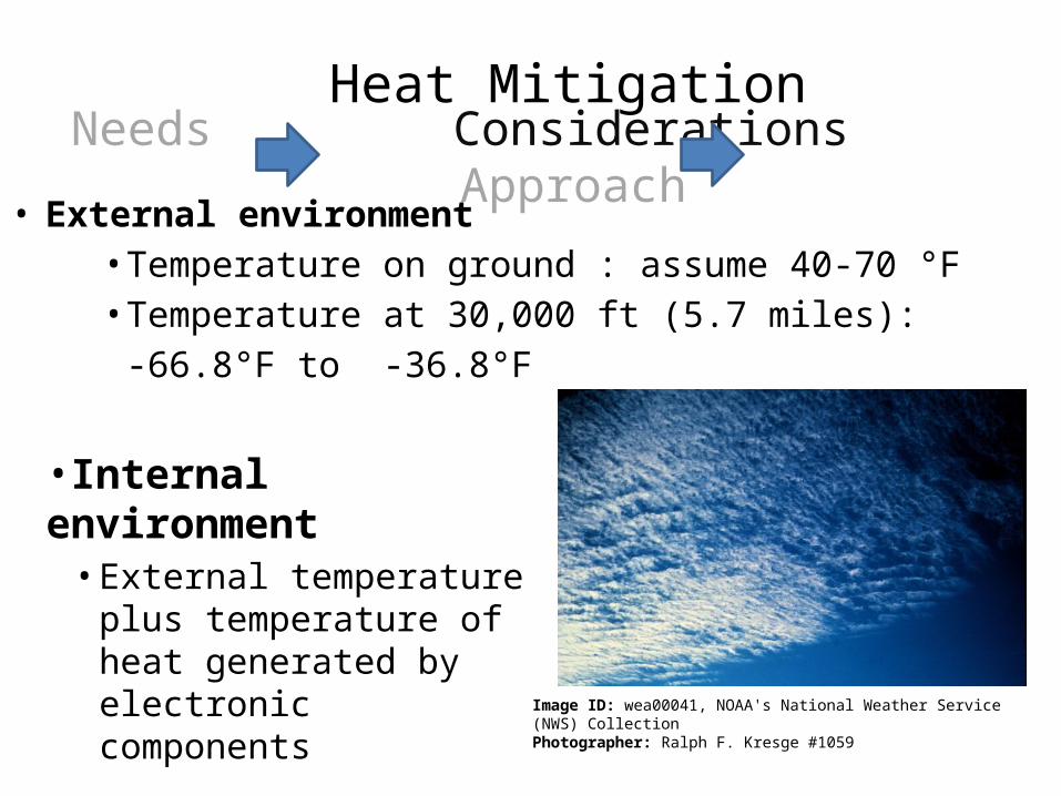
• External environment• Temperature on ground : assume 40-70 °F• Temperature at 30,000 ft (5.7 miles):
-66.8°F to -36.8°F
Image ID: wea00041, NOAA's National Weather Service (NWS) Collection Photographer: Ralph F. Kresge #1059
•Internal environment• External temperature plus
temperature of heat generated by electronic components
Needs Considerations ApproachHeat Mitigation
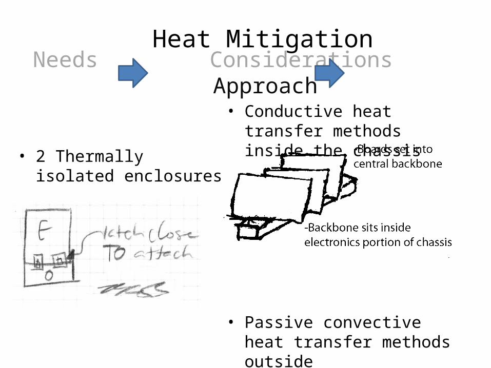
• 2 Thermally isolated enclosures
• Conductive heat transfer methods inside the chassis
• Passive convective heat transfer
methods outside
Needs Considerations ApproachHeat Mitigation

• Ensure imaging system is securely attached to airframe
• Reduce vibration of system
Image from: www.airamericafc.com/imaging/
Needs Considerations Approach
Airframe Mounting
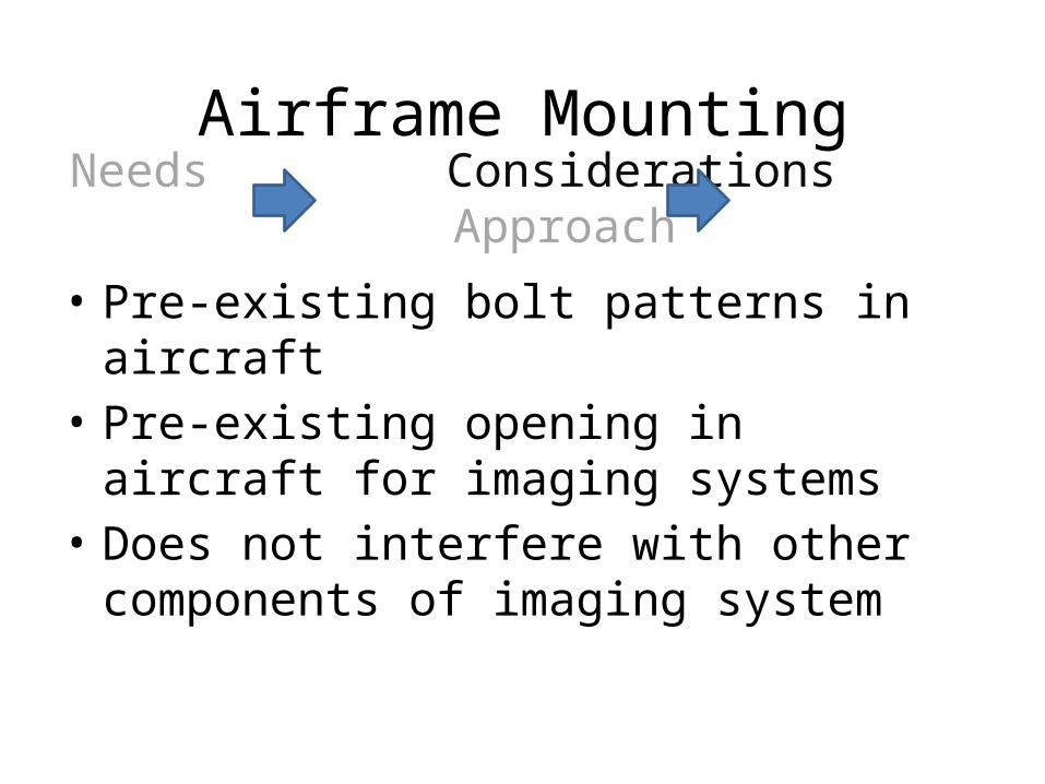
• Pre-existing bolt patterns in aircraft• Pre-existing opening in aircraft for imaging
systems• Does not interfere with other components of
imaging system
Needs Considerations Approach
Airframe Mounting
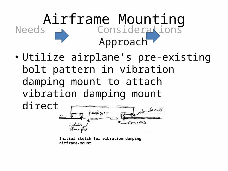
• Utilize airplane’s pre-existing bolt pattern in vibration damping mount to attach vibration damping mount directly to airframe
Initial sketch for vibration damping airframe-mount
Needs Considerations ApproachAirframe Mounting
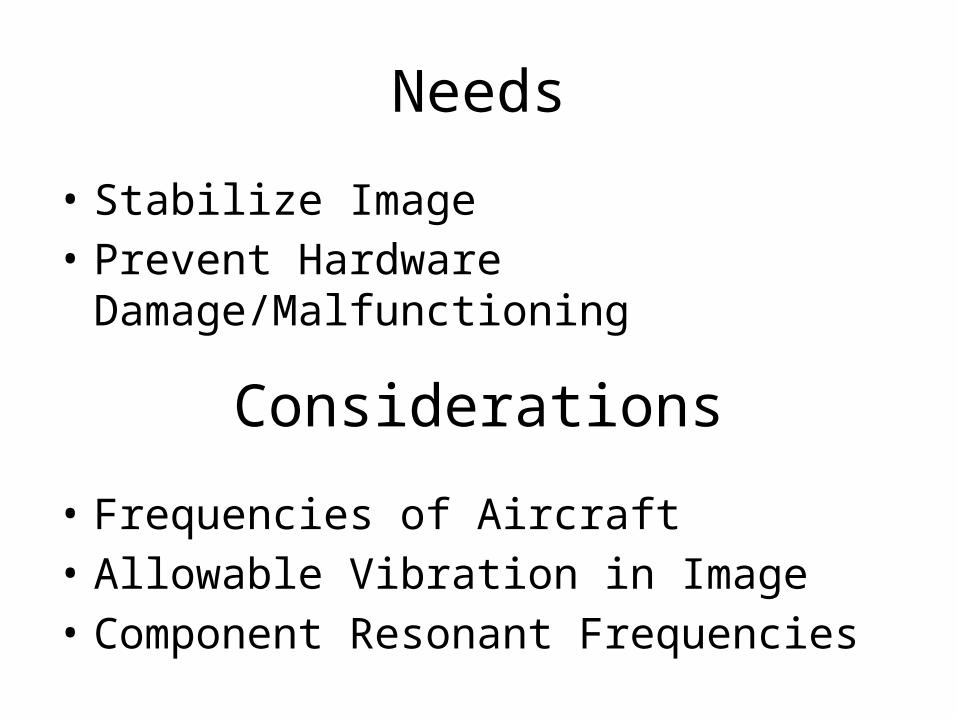
Needs
• Stabilize Image• Prevent Hardware Damage/Malfunctioning
Considerations
• Frequencies of Aircraft• Allowable Vibration in Image• Component Resonant Frequencies
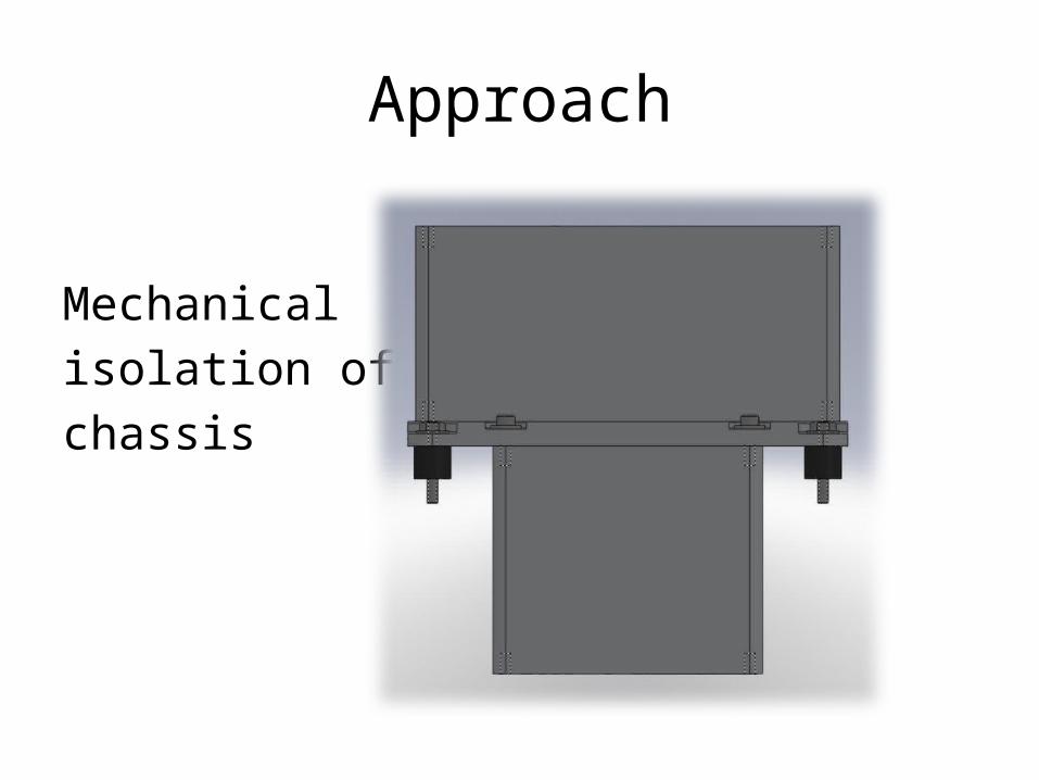
Approach
Mechanical isolation of chassis
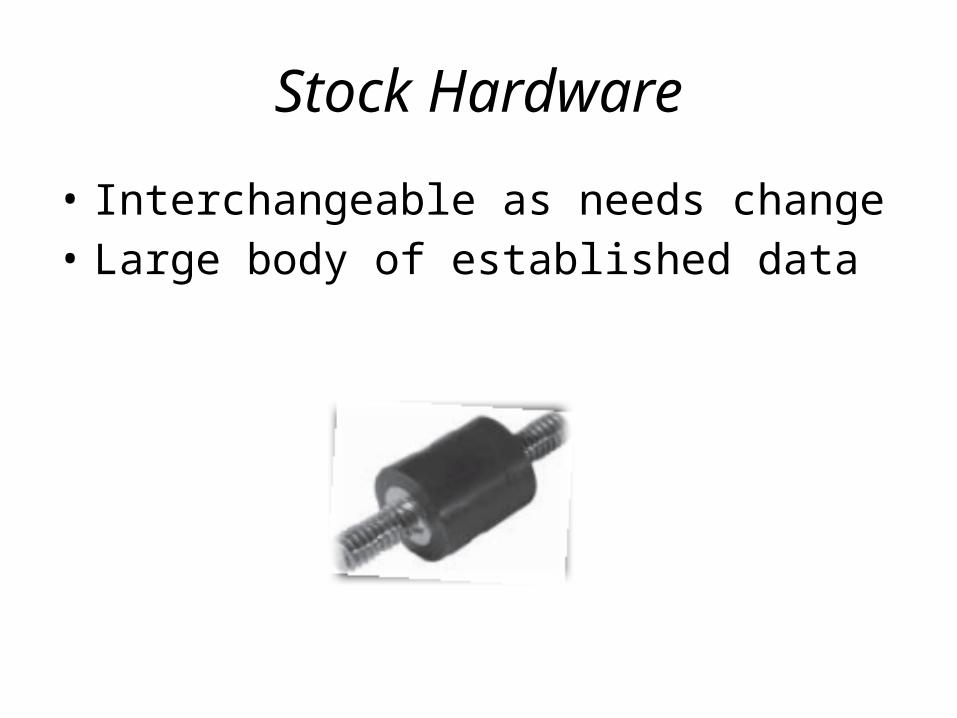
Stock Hardware
• Interchangeable as needs change• Large body of established data

Chassis DesignPhase 1: Individual Compartments
Separate Enclosures Thermally Isolated
ModularMinimal Leak Paths
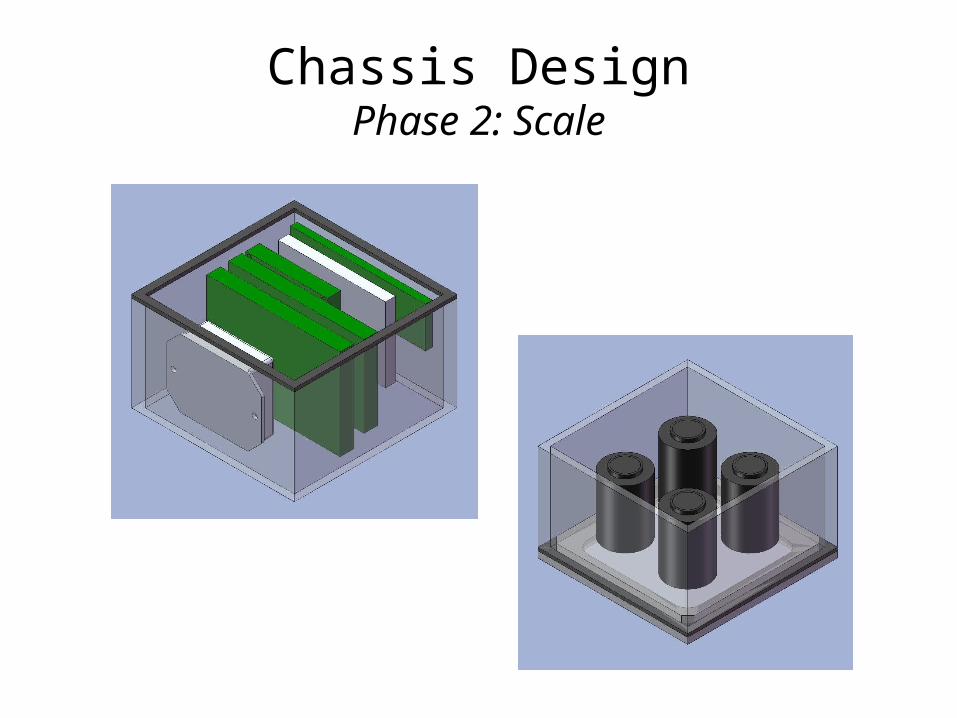
Chassis DesignPhase 2: Scale

Chassis DesignPhase 3: Detail
RIT Senior Design Project 10662D3 Engineering Camera Platform
Friday October 9, 2009