Embed Size (px)
Citation preview

Rittal PMC
USV-Manual
7857.3617857.3637857.365
Modular (n+1)-redundant3phase UPS System
10-40kVA
A3346302IT74-GB

A3346302IT74-GB 2
We reserve all rights for this technical documentation. It may neither be reproduced nor made available tothird parties without our prior consent. It may also in any other way not be utilised improperly by the recipientor third parties. Non-compliance involves payment of damages and may result in criminal liability.
CONTENTS1 SAFETY...................................................................................................................................................... 5
2 DESCRIPTION ........................................................................................................................................... 6
2.1 RELIABILITY AND QUALITY STANDARDS. .................................................................................... 62.2 POWER MODULAR CONCEPT MODELS........................................................................................ 62.3 SINGLE/PARALLEL-MODULES AND SINGLE/MULTI-CABINET CONFIGURATIONS .................. 62.4 WARRANTY....................................................................................................................................... 72.5 EXTENDED WARRANTY.................................................................................................................. 7
3 INSTALLATION.......................................................................................................................................... 8
3.1 INTRODUCTION................................................................................................................................ 83.1.1 Receipt of the UPS ........................................................................................................................ 83.1.2 Nameplate...................................................................................................................................... 8
3.2 UNPACKING...................................................................................................................................... 83.3 BATTERIES ....................................................................................................................................... 83.4 STORAGE.......................................................................................................................................... 9
3.4.1 UPS................................................................................................................................................ 93.4.2 Battery............................................................................................................................................ 9
3.5 POSITIONING.................................................................................................................................... 93.6 CABLING.......................................................................................................................................... 10
3.6.1 Connection Diagram .................................................................................................................... 103.6.2 Preparation for the Input Cabling................................................................................................. 103.6.3 Earthing........................................................................................................................................ 103.6.4 Connection of the Mains Supply .................................................................................................. 103.6.5 Single Input Feed......................................................................................................................... 113.6.6 Dual Input Feed ........................................................................................................................... 113.6.7 Preparation for the Output Cabling .............................................................................................. 123.6.8 Connection of the Load................................................................................................................ 123.6.9 Output Cabling ............................................................................................................................. 12
3.7 INTERNAL BATTERY MODULES................................................................................................... 163.8 EXTERNAL BATTERY CABINET AND BATTERY CONNECTION ................................................ 16
3.8.1 External Battery Configuration..................................................................................................... 163.8.2 Connection of External Battery Cabinet and PMC EXTENDED TWIN ....................................... 17
3.9 INTERFACING................................................................................................................................. 193.9.1 SMART PORT (Serial RS 232).................................................................................................... 193.9.2 DRY PORT (volt-free contacts) ................................................................................................... 20
4 OPERATION............................................................................................................................................. 21
4.1 COMMISSIONING ........................................................................................................................... 214.2 CONTROL PANEL........................................................................................................................... 21
4.2.1 Power Management Display (PMD) ............................................................................................ 214.2.2 LED Indicators ............................................................................................................................. 224.2.3 Keys ............................................................................................................................................. 224.2.4 ON/OFF Start-up and Shutdown Buttons .................................................................................... 224.2.5 Definition of a Single/Parallel-Module System (DIP Switch SW1-1) ........................................... 234.2.6 Definition of a Single/ Multi-Cabinet Chain (DIP Switch SW1-9)................................................. 23
4.3 DESCRIPTION OF THE LCD .......................................................................................................... 244.3.1 Status Screens............................................................................................................................. 244.3.2 Main Menu Screen....................................................................................................................... 244.3.3 Event Log Screen ........................................................................................................................ 244.3.4 Measurements Screen................................................................................................................. 25
A3346302IT74-GB 3
4.3.5 Commands Screen ...................................................................................................................... 254.3.6 UPS Data ..................................................................................................................................... 254.3.7 Set-Up User ................................................................................................................................. 264.3.8 Set-Up Service............................................................................................................................. 26
4.4 OPERATING MODES...................................................................................................................... 274.4.1 Mode "ON LINE" (INVERTER MODE) ........................................................................................ 274.4.2 Mode"OFF-LINE"(ECO- or BYPASS MODE).............................................................................. 274.4.3 "MAINTENANCE BYPASS" - Mode ............................................................................................ 284.4.4 Parallel Isolator (IA2) ................................................................................................................... 28
4.5 START-UP PROCEDURE ............................................................................................................... 294.6 SHUTDOWN PROCEDURE ............................................................................................................ 314.7 LOAD TRANSFER: FROM INVERTER OPERATION TO MAINTENANCE BYPASS.................... 324.8 LOAD TRANSFER: FROM MAINTENANCE BYPASS TO INVERTER OPERATIONS ................. 33
5 REPLACEMENT OF UPS-MODULE ....................................................................................................... 34
5.1 REPLACEMENT OF UPS-MODULE IN SINGLE-MODULE SYSTEMS ......................................... 345.1.1 How to Extract a UPS-Module in SINGLE MODULE Systems ................................................... 345.1.2 How to Fit Back a UPS-Module in SINGLE-MODULE-Systems ................................................. 35
5.2 REPLACEMENT OF UPS-MODULE IN REDUNDANT MULTI-MODULE SYSTEM ...................... 375.2.1 How to Extract a Module in Redundant Multi-Module System .................................................... 375.2.2 How to insert a module in a Redundant Multi Module System.................................................... 38
5.3 REPLACEMENT OF A MODULE IN CAPACITY MULTI-MODULE SYSTEM ................................ 395.3.1 How to Extract a Module in a Capacity Multi-Module System..................................................... 395.3.2 How to Fit Back a Module in a Capacity Multi-Module System ................................................... 40
6 MULTI-CABINET CONFIGURATION ...................................................................................................... 42
6.1 CONCEPT OF MULTI-CABINET CONFIGURATION...................................................................... 426.2 INSTALLATION INSTRUCTIONS.................................................................................................... 43
6.2.1 Introduction .................................................................................................................................. 436.2.2 Paralleling of UPS-Cabinets ........................................................................................................ 43
6.2.2.1 Connection of Parallel Communication Cables (BUS-lines) ............................................... 436.2.2.2 Parallel Adapater and DIP-Switch SW2-2........................................................................... 44
6.2.3 DIP-Switch SW1-1 and SW1-9 Settings...................................................................................... 446.2.4 ON/OFF – Main Buttons .............................................................................................................. 456.2.5 Parallel Isolator (IA2) ................................................................................................................... 456.2.6 Maintenance Bypass (IA1)........................................................................................................... 45
6.2.6.1 Redundant Parallel Configuration ....................................................................................... 466.2.6.2 Capacity Parallel Configuration........................................................................................... 46
6.2.7 ECO-MODE (BYPASS MODE) in Parallel Systems.................................................................... 466.3 COMMISSIONING OF MULTI-CABINET CONFIGURATION ......................................................... 46
6.3.1 Start-up of a Multi-Cabinet Configuration .................................................................................... 466.3.2 Shutdown of Multi-Cabinet Configuration .................................................................................... 466.3.3 Replacement of a Faulty UPS-Module in a Multi-Cabinet Configuration..................................... 47
7 MAINTENANCE ....................................................................................................................................... 48
7.1 INTRODUCTION.............................................................................................................................. 487.2 USER RESPONSIBILITIES ............................................................................................................. 487.3 ROUTINE MAINTENANCE.............................................................................................................. 487.4 BATTERY TEST .............................................................................................................................. 48
8 TROUBLESHOOTING ............................................................................................................................. 49
8.1 ALARMS........................................................................................................................................... 498.2 MENU, COMMANDS, EVENT LOG AND MEASUREMENTS ........................................................ 498.3 FAULT IDENTIFICATION AND RECTIFICATION........................................................................... 49
9 OPTIONS.................................................................................................................................................. 50
9.1 INTRODUCTION.............................................................................................................................. 509.2 REMOTE EMERGENCY FACILITIES ............................................................................................. 509.3 REMOTE SIGNALLING PANEL (RSP) ........................................................................................... 51
9.3.1 How to Connect the Remote Signalling Panel (RSP).................................................................. 529.4 GENERATOR ON FACILITIES........................................................................................................ 52
9.5 Power Modular Concept-Software Shutdown und Management Software.................................................53

A3346302IT74-GB 4
9.5.1 Why is UPS Management important?.......................................................................................... 539.5.2 Power Modular Concept-Software Shutdown and Monitoring Software ..................................... 53
9.6 SNMP CARD/ADAPTER FOR NETWORK MANAGEMENT /REMOTE MONITORING ................ 55

A3346302IT74-GB 5
1 Safety
BEFORE ATTEMPTING TO INSTALL OR START UP THIS UPS THE USER MUSTENSURE THAT THE SAFETY INSTRUCTIONS IN THIS MANUAL ARE CAREFULLYREAD AND OBSERVED BY TECHNICALLY COMPETENT PERSONNEL. KEEP THISMANUAL WITH THE UPS FOR FUTURE REFERENCE.THIS UPS MUST NOT BE STARTED UP OR PUT INTO USE WITHOUT HAVING BEENCOMMISSIONED BY A FULLY TRAINED AND AUTHORISED PERSON.
ALL SERVICING MUST BE PERFORMED ONLY BY QUALIFIED PERSONNEL. DONOT ATTEMPT TO SERVICE THE UPS YOURSELF.BY OPENING OR REMOVING THE UPS-COVERS YOU RUN RISK OF EXPOSURE TODANGEROUS VOLTAGES!
IN CASE OF ANY KIND OF DOUBT REGARDING THIS UPS, CONTACT:���� RITTAL GmbH & Co. KGAuf dem StützelbergD-35745 HerbornGermanyTel. +49 (0)2772-505-0Fax.+49 0)2772-505-2913e-mail: [email protected]
RITTAL GMBH & CO. KG WILL ASSUME NEITHER RESPONSIBILITY NOR LIABILITYDUE TO INCORRECT OPERATION OR MANIPULATION OF THE UPS.
HIGH LEAKAGE CURRENT!MAKE SURE THAT THE EARTHING IS CARRIED OUT CORRECTLY BEFORE YOUCONNECT THE MAINS POWER SUPPLY!
THE POWER MODULAR CONCEPT 10 – 40 kVA IS CLASS A - UPS-PRODUCT(ACCORDING TO EN 50091/Part-2).IN A DOMESTIC ENVIRONMENT IT MAY CAUSE RADIO INTERFERENCE. IN SUCHAN ENVIRONMENT THE USER MAY BE REQUIRED TO UNDERTAKE ADDITIONALMEASURES.
RITTAL GMBH & CO. KG HAS TAKEN EVERY PRECAUTION TO PRODUCE ANACCURATE, COMPLETE AND EASY TO UNDERSTAND MANUAL AND WILLTHEREFORE ASSUME NO RESPONSIBILITY NOR LIABILITY FOR DIRECT,INDIRECT OR ACCIDENTAL PERSONAL OR MATERIAL DAMAGE DUE TO ANYMISINTERPRETATION OR UNDESIRED MISTAKES IN THIS MANUAL.THIS MANUAL MAY NOT BE COPIED NOR REPRODUCED PRIOR TO WRITTENPERMISSION OF RITTAL GMBH & CO. KG.
USER MUST HANG A WARNING LABEL ON ALL PRIMARY UPS POWERISOLATORS. ELECTRICAL MAINTENANCE PERSONNEL SHOULD BE AWARE OFDANGEROUS VOLTAGES. THE WARNING LABEL SHOULD CARRY THEFOLLOWING WORDING:“ISOLATE UPS BEFORE WORKING ON THIS CIRCUIT”
!
!
!
!
!
A3346302IT74-GB 6
2 Description
2.1 RELIABILITY AND QUALITY STANDARDS
Congratulation on your purchase of the Power Modular Concept PMC.
The PMC will provide your critical equipment with a steady and reliable power supply for manyyears.
The unique and modular Concept PMC belongs to the newest generation of midrange 3phaseUPS-Systems. High reliability, low operating cost and excellent electrical performance are onlysome of the highlights of this innovative UPS solution.
The criteria and methods implemented at RITTAL for the design and manufacture correspond tothe most stringent quality standards.
RITTAL is certified successfully in every areas according to the model of the InternationalStandard ISO 9001/EN 29001. The Certification of UPS with the operating performanceaccording to the Norm IEC 62 040-3 and VDE 0558 Part 530 is accomplished. With it the RITTALUPS has the classification code VFl-SS-111.
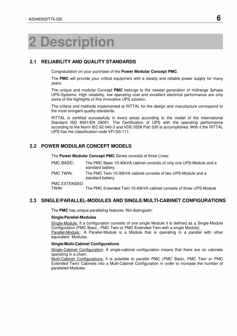
2.2 POWER MODULAR CONCEPT MODELS
The Power Modular Concept PMC Series consists of three Lines:
PMC BASIC: The PMC Basic 10-40kVA cabinet consists of only one UPS-Module and a standard battery.
PMC TWIN: The PMC Twin 10-30kVA cabinet consists of two UPS-Module and a standard battery.
PMC EXTENDEDTWIN: The PMC Extended Twin 10-40kVA cabinet consists of three UPS-Module
2.3 SINGLE/PARALLEL-MODULES AND SINGLE/MULTI-CABINET CONFIGURATIONS
The PMC has unique paralleling features. We distinguish:
Single/Parallel-Modules
Single-Module: If a configuration consists of one single Module it is defined as a Single-ModuleConfiguration (PMC Basic , PMC Twin or PMC Extended Twin with a single Module).Parallel-Module:. A Parallel-Module is a Module that is operating in a parallel with otherequivalent Modules.
Single/Multi-Cabinet Configurations
Single-Cabinet Configuration: A single-cabinet configuration means that there are no cabinetsoperating in a chain.Multi-Cabinet Configurations: It is possible to parallel PMC (PMC Basic, PMC Twin or PMCExtended Twin) Cabinets into a Multi-Cabinet Configuration in order to increase the number ofparalleled Modules.

A3346302IT74-GB 7
2.4 WARRANTY
The PMC is supplied with a limited warranty that the UPS and its component parts are free fromdefects in materials for a period of 12 months from the date of original commissioning or 15months from the date of original delivery, whichever is the sooner. Transportation cost is notincluded in the warranty and has to be paid by the end-user.
Do not return anything without written authorisation from RITTAL GmbH & Co. KG or your closestservice centre. RITTAL or the closest service centre will then give you further instructions how toproceed.
Any product must be returned with transportation charges prepaid and must be accompanied bya description of the failure. Products without description will not be handled.
This warranty is invalidated if the UPS is put into use without having been commissioned by afully trained and by RITTAL authorised person.
This warranty does not apply to any damage or losses caused by misuse, abuse, negligence,neglect, unauthorised repair or modification, incorrect installation, inappropriate environment,accident, act of God or inappropriate application.
If the UPS fails to conform to the above within the warranty period then RITTAL GmbH & Co. KGor an authorized service centre will, at its sole option, repair or replace the UPS or parts of it. Allrepaired or replaced parts will remain the property of RITTAL or of the authorized service centre.
RITTAL is not liable for any costs, such as loss of profits or revenue, loss of equipment, loss ofdata or software, cost of substitutes, claims by third parties or otherwise.
As general policy, RITTAL GmbH & Co. KG does not recommend the use of any of its productsin life support applications where failure or malfunction of the RITTAL product can be reasonablyexpected to cause failure of the life support device or to significantly affect us safety oreffectiveness. RITTAL GmbH & Co. KG does not recommend the use of any of its products indirect patient care. RITTAL will not knowingly sell its products for use in such applications unlessit receives in writing assurances satisfactory to RITTAL that the risks of injury or damage havebeen minimized, the customer assumes all such risks and the liability RITTAL is adequatelyprotected under the circumstances.
The UPS may contain batteries that must be re-charged for a minimum of 24 hours every 6months to prevent deep discharging. Batteries that have been, for whatever reason, deepdischarged are not covered by the warranty.
2.5 EXTENDED WARRANTY
The standard warranty may be enhanced by protecting the UPS with an Extended WarrantyAgreement (maintenance contract).
For more details please contact the nearest representative.
!

A3346302IT74-GB 8
3 Installation
3.1 INTRODUCTION
This chapter contains all the necessary information for the correct unpacking, positioning, cablingand installation of the PMC.
ALL THE OPERATIONS IN THIS SECTION MUST BE PERFORMED BYAUTHORISED ELECTRICIANS OR BY QUALIFIED PERSONNEL.RITTAL will take no responsibility for any personal or material damage causedby incorrect cabling or operations or activities, which are not carried out as perthe instructions contained in this manual.
3.1.1 Receipt of the UPS
Upon receiving the UPS, carefully examine the packing container and the UPS for any sign ofphysical damage. In case of rupture or suspect inform immediately:
a) The carrier and
b) RITTAL GmbH & Co. KG.
Ensure that the received UPS corresponds to the material indicated in the delivery note.
The packing container of the PMC protects it from mechanical and environmental damage. Toincrease its protection the UPS is wrapped with a plastic sheet.
3.1.2 Nameplate
The technical specifications of the PMC are provided on the nameplate, which is situated at thefront of the UPS. Check if it corresponds to the purchased material mentioned in the deliverynote.
3.2 UNPACKING
When unpacking the UPS observe the "FRAGILE" and "ARROW" on the packing container.
Perform the following steps to unpack the UPS:
• Cut wrappers and remove packing container by pulling it upwards;
• Remove the plastic cover from the UPS;
• Remove pallet from the UPS;
• Retain the packaging materials for future shipment of the UPS;
• Examine the UPS for any sign of damage. Notify your carrier or supplier immediately ifdamage is apparent.
• Open the UPS-door and make sure that all the UPS-Mudules are appropriately fittedin their UPS-Compartment and if the UPS system is provided without a UPS-modulemake sure that the empty UPS-compartment is correctly covered with the UPS-compartment protection cover.
3.3 BATTERIES
The standard batteries of the PMC are sealed, maintenance-free batteries, mounted in anexternal battery cabinet and will typically be connected when the UPS is commissioned.
The battery life depends very much on the ambient temperature. A temperature range between+18° and +23°C will achieve the optimum battery life.
If the UPS is delivered without batteries, RITTAL is not responsible for any damage ormalfunctioning caused to the UPS by incorrect wiring.
!

A3346302IT74-GB 9
3.4 STORAGE
3.4.1 UPS
If you plan to store the UPS prior to use, keep the UPS unpacked in a dry, clean and cool storageroom with an ambient temperature between (+5 °C to +40°C) and humidity of less than 90%.
If the packing container is removed protect the UPS from dust.
3.4.2 Battery
The battery life depends very much on the ambient temperature.
It is therefore important not to store the battery longer than 6 months at 20°C, 3 months at 30°Cand 2 months at 35°C storage temperature without a battery recharge.
For longer-term storage make sure that the battery is fully recharged every 6 months.
SEALED BATTERIES MUST NEVER BE STORED IN A DISCHARGED OR PARTIALLYDISCHARGED STATE.
EXTREME TEMPERATURE, UNDER- AND OVERCHARGE AND OVERDISCHARGE WILLDESTROY BATTERIES!
Before and after storing, charge the battery.
Always store the batteries in a dry, clean, cool environment in their original packaging.
If the packing container is removed protect the batteries from dust and humidity.
3.5 POSITIONING
The PMC is a compact and light UPS and can easily be moved to the final position.
All parts of the PMC are accessible from the front and rear making it a service-friendly andmaintenance-friendly UPS.
The UPS should be located where:
• Humidity and temperature are within prescribed limits;
• Fire protection standards are respected;
• Cabling can be performed easily;
• Available front accessibility for service or periodic maintenance;
• Requested air cooling flow should be granted;
• The air conditioning system should have sufficient capacity;
• Dust or corrosive/explosive gases must be absent;
• The place is vibration free;
• Minimum 10cm rear space is recommended for proper cooling (see Figure 3.1 and 3.2);
• Only front access is necessary for service and maintenance.
Clearances X Clearances X
Minimum 100mm Minimum 100mm
UPS
X
BatteryCabinet
UPS
X
Figure 3.1: UPS space recommendation Figure 3.2: UPS + Battery cabinetspace recommendation

A3346302IT74-GB 10
3.6 CABLING
3.6.1 Connection Diagram
To ensure correct operation of the UPS and its ancillary equipment it is necessary to provide themains cables with appropriate fuse protection.
To connect the PMC to the mains power supply see Figures 3.3, 3.4 and 3.5.
ALL THE OPERATIONS IN THIS MANUAL MUST BE PERFORMED BYAUTHORISED ELECTRICIANS OR BY QUALIFIED INTERNAL PERSONNEL.DO NOT OPERATE IN CASE OF PRESENCE OF WATER OR MOISTURE.BY OPENING OR REMOVING THE UPS-COVERS YOU RUN RISK OF EXPOSURETO DANGEROUS VOLTAGES!
3.6.2 Preparation for the Input Cabling
Before you start connecting the UPS, ensure that:
• MAINS VOLTAGE (INPUT VOLTS) AND FREQUENCY (FREQUENCY)CORRESPOND TO THE VALUES INDICATED ON THE NAMEPLATE OF THE UPS.
• EARTHING IS PERFORMED IN ACCORDANCE WITH THE PRESCRIBED IECSTANDARDS OR WITH LOCAL REGULATIONS;
• UPS IS CONNECTED TO THE MAINS THROUGH A LV-DISTRIBUTION BOARDWITH A SEPARATE MAINS LINE (PROTECTED WITH A CIRCUIT BREAKER ORFUSE) FOR THE UPS.
Provide input fuses and cables according to Figure 3.4 or in accordance with the prescribed IECStandards or with the local regulations.
The input of the UPS must be fitted with circuit breakers or other kind of protection. The circuitbreakers will be connected between the mains supply and the UPS and will provide additionalprotection to the UPS in the event of overloads and short circuits.
3.6.3 Earthing
ALL THE OPERATIONS IN THIS SECTION MUST BE PERFORMED BYAUTHORISED ELECTRICIANS OR BY QUALIFIED TRAINED INTERNALPERSONNEL.
To ensure protection of personnel during the installation of UPS make sure that the connectionsare performed under the following conditions:
• No mains voltage is present;
• Loads are shut down and disconnected;
• PMC is shut down and voltage-free.
Connect the earthing wire coming from the LV-Distribution Board to the terminal "PE".
Under the connection terminal of the UPS there is a cable-fixing rail to ensure that the cableshave been fastened properly.
3.6.4 Connection of the Mains Supply
After the UPS has been unpacked and brought to its final position the authorized technician maystart with the cabling.
ALL THE OPERATIONS IN THIS SECTION MUST BE PERFORMED BYAUTHORISED ELECTRICIANS OR BY QUALIFIED INTERNAL PERSONNEL.
To ensure protection of the personnel during the installation of the UPS make sure that theconnections are performed under the following conditions:
• No mains voltage is present;
• All loads are shut down and disconnected;
• PMC is shut down and voltage-free.
!
!
!

A3346302IT74-GB 11
Remove the terminal cover of the UPS
Before connecting the input power cables make sure that:
• UPS-Module is fitted in its correct position;
• Maintenance Bypass IA1 is open in position OFF;
• Parallel Isolators IA2 are in position OFF
Connect the input power cable coming from the LV-Distribution Board to the terminals of the UPSshowed in the following pages, keeping the phase rotation in clock-wise sense.
NOTE: Neutral input wire must always be connected!
NOTE: The PMC is provided with facilities for both single feed (one common input cable forrectifier and bypass) and dual feed (separate input cable for rectifier and bypass).
The standard PMC is always supplied with facilities for a single feed.
If dual feed is required please contact your nearest Service Centre.
3.6.5 Single Input Feed
To achieve correct Input Cabling see Drawing in Figure 3.5.
For single input feed connect the mains input cable to UPS Terminal Block according to thefollowing table:
MAINS INPUT CABLE UPS TERMINAL
Phase L1 1L1
Phase L2 1L2
Phase L3 1L3
NEUTRAL 1N
EARTH PE
For minimum recommended Input Cable Sections and Fuse Ratings for the PMC ExtendedTwin see table in Figure 3.4.
Under the connection terminal of the UPS there is a cable-fixing rail to ensure that the cableshave been fastened properly.
3.6.6 Dual Input Feed
To achieve correct input cabling see Terminal Block in Figure 3.5.
NOTE: The UPS is supplied (as standard version) with facilities for a single cable feed (forrectifier and bypass).
If dual feed is required, please contact your nearest service centre.For dual input feed connect the mains input cables to UPS Terminal according to followingtables:
MAINS INPUT CABLE UPS TERMINAL BYPASS INPUT CABLE UPS TERMINAL
Phase L1 1L1 Phase L1 2L1Phase L2 1L2 Phase L2 2L2
Phase L3 1L3 Phase L3 2L3
NEUTRAL 1N NEUTRAL 2N
EARTH PE EARTH PE
For minimum recommended Input Cable Sections and Fuse Ratings PMC Extended Twin seetable in Figure 3.4.
Under the connection terminal of the UPS there is a cable-fixing rail to ensure that the cableshave been fastened properly.
!

A3346302IT74-GB 12
3.6.7 Preparation for the Output Cabling
Before you start connecting the loads, ensure that the sum of the indicated UPS-module ratedpowers (OUTPUT POWER) on the nameplates (on the front side of the UPS-modules) is equal toor larger than the total load requirements.
The output of the UPS must be fitted with circuit breakers or other kind of protection. Thesecircuit breakers will be connected between the loads and the UPS and will provide additionalprotection to the UPS in the event of overloads and short circuits.
These circuit breakers will enable the protection of each load separately.
The size of the circuit breakers depends on the load rating of the load sockets.
The circuit breakers must comply with the prescribed IEC Standards. It is recommended toprovide a separate output distribution board for the load.
The following values should be indicated on the output distribution board:
• Maximum total load rating;
• Maximum load rating of the load sockets.
• If a common distribution board is used (sockets for Mains and UPS voltage), ensurethat on each socket there is an indication of the applied voltage (“Mains” or “UPS”).
Output power cable ratings should be in accordance with the recommended cable sections andfuses ratings or in accordance with the prescribed IEC Standards or with the local regulations.
Under the connection terminal of the UPS there is a cable-fixing rail to ensure that the cableshave been fastened properly.
Ensure that the earthing is performed in accordance with the prescribed IEC Standards or withthe local regulations.
3.6.8 Connection of the Load
ALL THE OPERATIONS IN THIS SECTION MUST BE PERFORMED BYAUTHORISED ELECTRICIANS OR BY QUALIFIED INTERNAL PERSONNEL
To ensure protection of the personnel during the installation of the UPS make sure that theconnections are performed under the following conditions:
• No mains voltage is present;
• All loads are shut down and disconnected;
• PMC is shut down and voltage-free.
Before connecting the output power cables make sure that:
• UPS-Module is fitted in its correct position;
• Maintenance bypass is in position OFF;
• Parallel Isolators IA2 is in position OFF
Remove the terminal cover of the UPS.
Connect the output power cable coming from the LV-Distribution Board to the terminals of theUPS as shown in drawing of Figure 3.5.
3.6.9 Output Cabling
To achieve correct Output Cabling see Terminal Block in Figure 3.5.
For output cabling connect output cable to UPS Terminal according to following Output to UPSterminal block correlation.
OUTPUT CABLE UPS TERMINAL
Phase L1 3L1
Phase L2 3L2
Phase L3 3L3
NEUTRAL 3N
EARTH PEUnder the connection terminal of the UPS there is a cable-fixing rail to ensure that the cableshave been fastened properly.
!

A3346302IT74-GB 13
Block Diagram Extended Twin
Figure 3.3: Block Diagram PMC Extended Twin
STANDARD VERSION (SINGLE FEED INPUT)Power (kVA) Fuse A (Agl/CB) Cable A (IEC 60950-1:2001) Cable D (IEC 60950-1:2001) Fuse E +/N/- Cable E +/N/-
10 3x63 5x10 5x10 3x32A 3x410+10 3x63 5x10 5x10 3x63A* 3x10*
10+10+10 3x63 5x10 5x10 3x100A* 3x25*15 3x100 5x25 5x25 3x63A 3x10
15+15 3x100 5x25 5x25 3x100A* 3x25*15+15+15 3x100 5x25 5x25 3x125A* 3x35*
20 3x100 5x25 5x25 3x63A 3x10²⁰+20 3x100 5x25 5x25 3x125A* 3x35*
20+20+20 3x100 5x25 5x25 3x160A* 3x50*30 3x125 5x35 5x35 3x80A 3x16
30+30 3x125 5x35 5x35 3x125A* 3x35*30+30+30 3x125 5x35 5x35 3x200A* 3x70*
40 3x200 5x70 5x70 3x100A 3x2540+40 3x200 5x70 5x70 3x160A* 3x50*
40+40+40 3x200 5x70 5x70 3x250A* 3x120*
VERSION ON REQUEST (DUAL FEED INPUT)
Power (kVA)Fuse B
(Agl/CB)Cable B
(IEC 60950-1:2001)Fuse C
(Agl/CB)Cable C
(IEC 60950-1:2001)Cable D
(IEC 60950-1:2001)Fuse E
+/N/-Cable E
+/N/-
10 3x63 5x10 3x63 4x10 5x10 3x32A 3x410+10 3x63 5x10 3x63 4x10 5x10 3x63A* 3x10*
10+10+10 3x63 5x10 3x63 4x10 5x10 3x100A* 3x25*15 3x100 5x25 3x100 4x25 5x25 3x63A 3x10
15+15 3x100 5x25 3x100 4x25 5x25 3x100A* 3x25*15+15+15 3x100 5x25 3x100 4x25 5x25 3x125A* 3x35*
20 3x100 5x25 3x100 4x25 5x25 3x63A 3x10²⁰+20 3x100 5x25 3x100 4x25 5x25 3x125A* 3x35*
20+20+20 3x100 5x25 3x100 4x25 5x25 3x160A* 3x50*30 3x125 5x35 3x125 4x35 5x35 3x80A 3x16
30+30 3x125 5x35 3x125 4x35 5x35 3x125A* 3x35*30+30+30 3x125 5x35 3x125 4x35 5x35 3x200A* 3x70*
40 3x200 5x70 3x200 4x70 5x70 3x100A 3x2540+40 3x200 5x70 3x200 4x70 5x70 3x160A* 3x50*
40+40+40 3x200 5x70 3x200 4x70 5x70 3x250A* 3x120*
*only valid for common battery use
STANDARD VERSION (SINGLE FEED INPUT)
MAINS (3x380V/220V,3x400/230V,3x415/240V
Maintenance Bypass IA1
Cable D
Load
ExtendedTwinFrame
UPS module 1
F1 F2
Static Switch
IA2-1
Inverter
Rectifier
Fuse A
Cable A
F1 F2
IA2-2
Inverter
Rectifier
Static Switch
UPS module 2
UPS module 3
IA2-3
Inverter
Rectifier
F1 F2
Static Switch
Cable E
FuseE
Cable B Cable C
MAINS (3x380V/220V,3x400/230V,3x415/240V
Fuse B
VERSION ON REUQEST (DUAL FEED INPUT)
Cable D
Load
ExtendedTwinFrame
Fuse C
Maintenance Bypass IA1
F1 F2
Static Switch
UPS module 2
Inverter
Rectifier
IA2-2
Static Switch
UPS module 1
Inverter
Rectifier
F2F1
IA2-1 IA2-3
F1 F2
Static Switch
UPS module 3Rectifier
Inverter
Cable E
FuseE
A3346302IT74-GB 14
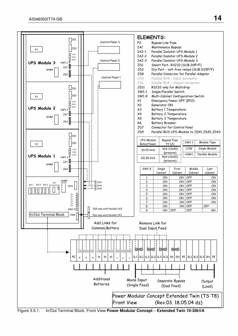
Figure 3.5.1: In/Out Terminal Block, Front View Power Modular Concept – Extended Twin 10-30kVA
ELEMENTS:F2 Bypass Line Fuse
IA1 Maintenance Bypass
IA2-1 Parallel Isolator UPS-Module 1
IA2-2 Parallel Isolator UPS-Module 2
IA2-3 Parallel Isolator UPS-Module 3
JD1 Smart Port- RS232 (SUB-D9P/F)
JD2 Dry Port - volt-free relays (SUB-D25P/F)
JD8 Parallel Connector for Parallel Adapter
JD11 RS232 only for Multidrop
SW1-1 Single/Parallel Switch
SW1-9 Multi-Cabinet Configuration Switch
X1 Emergency Power OFF (EPO)
X2 Generator ON
X3 Battery 1 Temperature
X4 Battery 2 Temperature
X5 Battery 3 Temperature
X6 Battery Breaker
JD7 Connector for Control Panel
JD4 Parallel BUS UPS-Module to JD41,JD42,JD43
Power Modular Concept Extended Twin (TS T8)
Front View (Rev.03. 18.05.04 dz)
Control Panel 2
JD2
SNMP
SW1-1
F2
JD1
JD7
JD4
JD2
SNMP
SW1-1
F2
JD1
JD7
JD4
Control Panel 3
JD2
SNMP
SW1-1
F2
JD1
JD7
JD4
Control Panel 1
UPS-Module
Rated Power
Bypass Fuse
F2 (A)
10/15 kVA 32A (14x51)
(pronorm)
20/30 kVA 50A (14x51)
(pronorm)
SW1-9
JD8In/Out Terminal Block
Mains Input
(Single Feed)
Remove Link for
Dual Input Feed
Additional
BatteriesSeparate Bypass
(Dual Feed)Output
(Load)
1L1 2L1 1L2 2L2 1L3 2L3 1N 2N PE 3L1 3L2 3L3 3N PE+ N N N _ _ _++PE
Add Links for
Common Battery
SW1-9 Single
Cabinet
First
Cabinet
Middle
Cabinet
Last
Cabinet
1 ON ON OFF ON
2 ON ON OFF ON
3 ON ON OFF ON
4 ON ON OFF ON
5 ON ON OFF ON
6 ON ON OFF ON
7 ON ON OFF ON
8 ON ON OFF OFF
9 ON OFF OFF ON
SW1-1 Module Type
LOW Single Module
HIGH Parallel Module
X6
X1
X2
X3
X4
X5
IA2-2 IA2-3 IA2-1
UPS Module 3
UPS Module 2
UPS Module 1
JD11
X1/M
X2/M
X3/M
X1/M
X2/M
X3/M
X1/M
X2/M
X3/M
JD43
JD41
JD42
1.1.1
IA1 SNMP
JD5 only with Parallel UPS
JD6 only with Parallel UPS
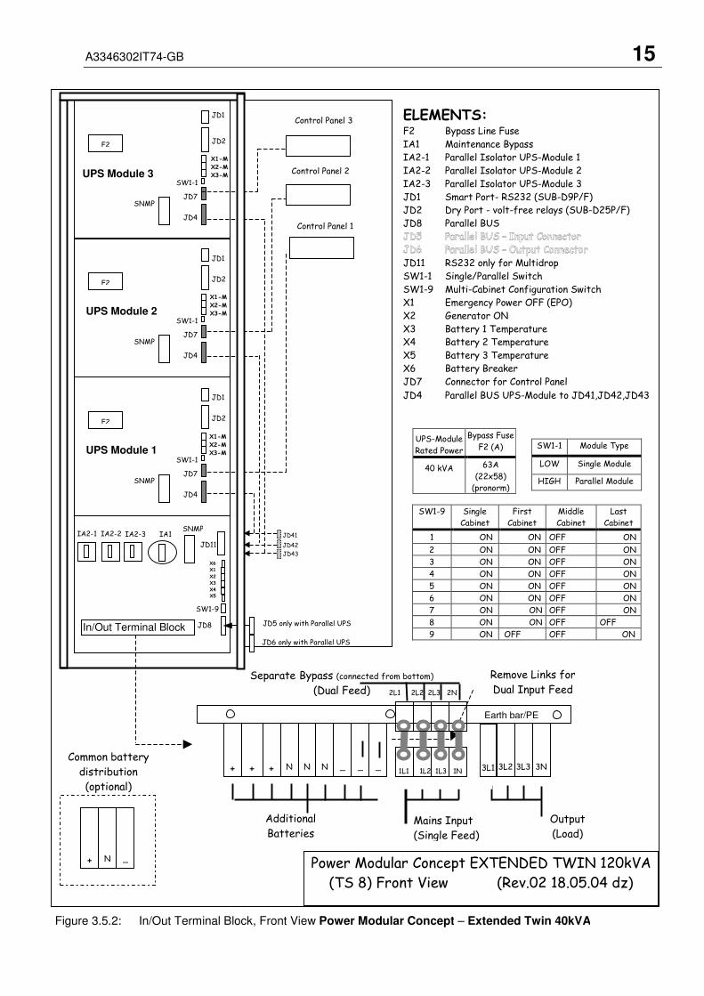
A3346302IT74-GB 15
ELEMENTS:F2 Bypass Line Fuse
IA1 Maintenance Bypass
IA2-1 Parallel Isolator UPS-Module 1
IA2-2 Parallel Isolator UPS-Module 2
IA2-3 Parallel Isolator UPS-Module 3
JD1 Smart Port- RS232 (SUB-D9P/F)
JD2 Dry Port - volt-free relays (SUB-D25P/F)
JD8 Parallel BUS
JD11 RS232 only for Multidrop
SW1-1 Single/Parallel Switch
SW1-9 Multi-Cabinet Configuration Switch
X1 Emergency Power OFF (EPO)
X2 Generator ON
X3 Battery 1 Temperature
X4 Battery 2 Temperature
X5 Battery 3 Temperature
X6 Battery Breaker
JD7 Connector for Control Panel
JD4 Parallel BUS UPS-Module to JD41,JD42,JD43
UPS-Module
Rated Power
Bypass Fuse
F2 (A)
40 kVA 63A
(22x58)
(pronorm)
SW1-9 Single
Cabinet
First
Cabinet
Middle
Cabinet
Last
Cabinet
1 ON ON OFF ON
2 ON ON OFF ON
3 ON ON OFF ON
4 ON ON OFF ON
5 ON ON OFF ON
6 ON ON OFF ON
7 ON ON OFF ON
8 ON ON OFF OFF
9 ON OFF OFF ON
SW1-1 Module Type
LOW Single Module
HIGH Parallel Module
Power Modular Concept EXTENDED TWIN 120kVA
(TS 8) Front View (Rev.02 18.05.04 dz)
+ N _
Common battery
distribution
(optional)
Control Panel 2UPS Module 3
JD2
SNMP
SW1-1
F2
JD1
JD7
JD4
X1-M
X2-M
X3-M
UPS Module 2
JD2
SNMP
SW1-1
F2
JD1
JD7
JD4
X1-M
X2-M
X3-M
UPS Module 1
JD2
SNMP
SW1-1
F2
JD1
JD7
JD4
Control Panel 1
X1-M
X2-M
X3-M
In/Out Terminal Block
SW1-9
JD8
IA2-2 IA2-3 IA2-1
JD5 only with Parallel UPS
JD6 only with Parallel UPS
IA1
Control Panel 3
Figure 3.5.2: In/Out Terminal Block, Front View Power Modular Concept – Extended Twin 40kVA
Mains Input
(Single Feed)
Additional
Batteries
Output
(Load)
3L2 3L3 3N+ N N N _ _ _++ 1L1 1L2 1L3 1N
2L1 2L2 2L3 2N
Remove Links for
Dual Input FeedSeparate Bypass (connected from bottom)
(Dual Feed)
Earth bar/PE
3L1
X6 X1
X2
X3
X4 X5
SNMP
JD43
JD41
JD42 JD11
A3346302IT74-GB 16
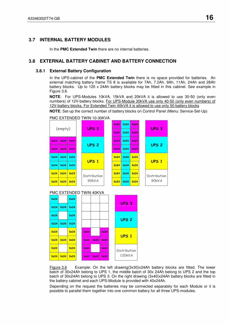
3.7 INTERNAL BATTERY MODULES
In the PMC Extended Twin there are no internal batteries.
3.8 EXTERNAL BATTERY CABINET AND BATTERY CONNECTION
3.8.1 External Battery Configuration
In the UPS-cabinet of the PMC Extended Twin there is no space provided for batteries. Anexternal matching battery frame TS 8 is available for 7Ah, 7.2Ah, 9Ah, 11Ah, 24Ah and 28Ahbattery blocks. Up to 120 x 24Ah battery blocks may be fitted in this cabinet. See example inFigure 3.6.
NOTE: For UPS-Modules 10kVA, 15kVA and 20kVA it is allowed to use 30-50 (only evennumbers) of 12V-battery blocks. For UPS-Module 30kVA use only 40-50 (only even numbers) of12V-battery blocks. For Extended Twin 40kVA it is allowed to use only 50 battery blocks
NOTE: Set-up the correct number of battery blocks on Control Panel (Menu: Service-Set-Up)
PMC EXTENDED TWIN 10-30KVA
5x24 5x24 5x24
(empty) UPS 35x24 5x24 5x24
UPS 3
5x24 5x24 5x24 5x24 5x24 5x24
5x24 5x24 5x24
UPS 25x24 5x24 5x24
UPS 2
5x24 5x24 5x24 5x24 5x24 5x24
5x24 5x24 5x24
UPS 15x24 5x24 5x24
UPS 1
5x24 5x24 5x24 5x24 5x24 5x24
5x24 5x24 5x24
Distribution
90kVA 5x24 5x24 5x24
Distribution
90kVA
PMC EXTENDED TWIN 40KVA
5x24 5x24
5x24 5x24 5x24
UPS 3
5x24 5x24
5x24 5x24 5x24
UPS 2
5x24 5x24 5x24 5x24
5x24 5x24 5x24 5x24 5x24 5x24
UPS 1
5x24 5x24 5x24 5x24
5x24 5x24 5x24 5x24 5x24 5x24
Distribution
120kVA
Figure 3.6 Example: On the left drawing(3x30)x24Ah battery blocks are fitted. The lowerbatch of 30x24Ah belong to UPS 1, the middle batch of 30x 24Ah belong to UPS 2 and the topbatch of 30x24Ah belong to UPS 3. On the right drawing (3x40)x24Ah battery blocks are fitted inthe battery cabinet and each UPS-Module is provided with 40x24Ah.
Depending on the request the batteries may be connected separately for each Module or it ispossible to parallel them together into one common battery for all three UPS-modules.

A3346302IT74-GB 17
3.8.2 Connection of External Battery Cabinet and Power Modular Concept ExtendedTwin
ALL THE OPERATIONS IN THIS MANUAL MUST BE PERFORMED BYAUTHORISED ELECTRICIANS OR BY QUALIFIED INTERNAL PERSONNEL.DO NOT OPERATE IN CASE OF PRESENCE OF WATER OR MOISTURE.BY OPENING OR REMOVING THE UPS-COVERS YOU RUN RISK OF EXPOSURETO DANGEROUS VOLTAGES!
It is normally recommended for redundant Multi-Module systems to provide each UPS-Modulewith its own separate battery. In this way the redundancy is extended also to the batteries. In theFigure 3.7 the drawing shows how to connect the batteries in the external battery cabinet and thePMC Extended Twin.
If the three battery batches are desired to be used as one common battery for all three UPS-Modules then Battery Links may be connected as shown below.
External Battery Cabinet PMCTS 8 Extended Twin
Figure 3.7.1 Connection of external batteries for 10-30kVA
!
3+ N N N 1- 2- 3-2+1+PEPE1-N1+ 2-N2+ 3-N3+
Add Links for
Common Battery
BatteryFuses
forUPS 1
BatteryFuses
forUPS 2
BatteryFuses
forUPS 3

A3346302IT74-GB 18
External Battery Cabinet PMCTS 8 Extended Twin
To ensure protection of the personnel during the installation of the UPS make surethat the connections are performed under the following conditions:
• No mains voltage is present in the UPS
• All the loads are disconnected
• The UPS and the external battery are voltage-free
To verify the complete shut down of the PMC perform following steps:
1) Make sure that the fuses feeding the UPS in the input Distribution Board are all openand no power is fed to the UPS.
2) Make sure the "MAINTENANCE BYPASS"(IA1) is open (position "OFF”)
3) Make sure the battery fuses in the external battery cabinet are open.
4) Connect Earth (PE) between the UPS and external battery cabinet.
5) Connect the corresponding + , N, - terminals between UPS and external batterycabinet according to drawing in Figure 3.7.
!
BatteryFuses
forUPS 1
BatteryFuses
forUPS 2
BatteryFuses
forUPS 3
3+ N N N 1- 2- 3-2+1+PEPE 1-N1+ 2-N2+3-N3+ PE
For Common Battery
+ N -

A3346302IT74-GB 19
3.9 INTERFACING
The PMC is provided with two ports:
• SMART PORT (Serial RS 232);
• DRY PORT (volt-free contacts);
3.9.1 SMART PORT (Serial RS 232)
The SMART PORT JD1 is an intelligent RS 232 serial port that allows the UPS to be connectedto a computer. The connector is a standard D-Type, 9-pin, female.
When installed the optional SMART PORT, the PMC-Software allows the computer to monitorthe mains voltage and the UPS status continuously.
In the event of any changes the computer terminal will display a message. (For details see ourMonitoring Package: PMC-Software )*.
The Fig. 3.8 and 3.9 shows how to connect a PC to the UPS.
a) Fig. 3.8 in case the PC has a 9 pin serial port
b) Fig. 3.9 in case the PC has a 25 pin serial port
a) Interface Cable (UPS End) Interface cable (Computer End)(9-Pin, D-Type Male) (9-Pin, D-Type Female)
Connects to UPS Connects toSMART PORT Computer
Figure 3.8 Connector Cable - PC Serial Port with 9-Pin Connection
b) Interface Cable (UPS End) Interface cable (Computer End)(9-Pin, D-Type Male) (25-Pin, D-Type Female)
Connects to UPS Connects toSMART PORT Computer
Figure 3.9 Connector Cable – PC Serial Port with 25-pin Connection
1
2
3
9
.
.
.
5
1
2
3
9
.
.
.
5
1
2
3
9
.
.
.
5
1
2
3
25
.
.
.
7
.
.
.
.

A3346302IT74-GB 20
3.9.2 DRY PORT (volt-free contacts)
Description:
The DRY PORT JD2 (DB-25P/F) may be used for:
• Connection of remote emergency stop facilities (see paragraph 9.2);
• Connection of Remote Status Panel (see paragraph 9.3);
• Provision of signals for the automatic and orderly shutdown of servers
• or IBM AS400, etc.
Definition of PINs on DRY PORT JD2 (25 PIN):
Pin Contact Signal Function
1 NO Mains failure
2 NC ALARM MAINS_OK Mains present
3 C Common
4 NO Load on inverter
5 NC Message LOAD_ON_INV
6 C Common
7 NO Battery low
8 NC ALARM BATT_LOW Battery OK
9 C Common
10 NO Load on Mains (BYPASS mode)
11 NC Message LOAD_ON_MAINS
12 C Common
13 NO Common Alarm
14 NC ALARM COMMON_ALARM No Alarm Condition
15 C Common
16
-
19
NC Not Connected
20 Customer in
21 GND Customer in GND
22 PS_12 GND
23 PS_12 + 12V (Imax = 100 mA)
24 Not Connected
25 Not Connected
All volt free contacts are rated 60 VAC max. and 500 mA max.
Figure 3.10 DRY PORT (JD2) Connections
+12V

A3346302IT74-GB 21
4 Operation
4.1 COMMISSIONING
The PMC is a high quality electronic machine that must be commissioned by a fully trained andauthorized RITTAL field service engineer before being put into use.
The commissioning of the UPS involves the connection of the UPS and battery, the checking ofthe electrical installation and operating environment of the UPS, the controlled start-up andtesting of the UPS and customer training.
Any PMC-System not commissioned by a RITTAL field service engineer orauthorized service centre must be considered an electrical hazard and RITTALaccepts no responsibility for its safe operation or the safety of any personnel.Additionally, the manufacturer’s warranty is immediately invalidated if theUPS is put into use before it has been correctly commissioned.
4.2 CONTROL PANEL
The user-friendly control panel is composed of three parts:
• POWER MANAGEMENT LCD DISPLAY (PMD);
• LED INDICATORS;
• KEYS.
Figure 4.1 Control Panel.
4.2.1 Power Management Display (PMD)
The 2 x 20 character LCD simplifies the communication with the UPS and provides thenecessary monitoring information about the UPS.
The menu driven LCD enables the access to the:
• EVENT REGISTER;
• Monitor the input and output U, I, f, P,
• Battery runtime;
• To perform commands like start-up and shut-down of UPS and
• Load transfer from INVERTER to BYPASS and vice-versa;
• DIAGNOSIS (SERVICE MODE);
• Adjustments and testing.
LINE 2 BY PASS
BATTERY ALARM
LINE 1 INV
ON/OFF
RESET � � ENTER
ON/OFF
!
Power Modular Concept

A3346302IT74-GB 22
4.2.2 LED Indicators
The mimic diagram serves to indicate the general status of the UPS. The LED-indicators showthe power flow status and in the event of mains failure or load transfer from inverter to bypassand vice-versa. The corresponding LED-indicators will change colours from green (normal) to red(warning).
The LED’s LINE 1 (rectifier) and LINE 2 (bypass) indicate the availability of the mains powersupply.
The LED’s INVERTER and BYPASS if green indicate which of the two is supplying power to thecritical load. When the battery is supplying the load due to mains failure the LED-indicatorBATTERY is flashing.
The LED-indicator ALARM is a visual indication of any internal or external alarm condition. At thesame time an audible alarm will be activated.
INDICATOR INDICATOR STATUS MEANING
ALARM OFF
RED
No alarm condition
Alarm conditiont
LINE 1 GREEN
RED
Mains rectifier available
Mains rectifier not available
LINE 2 GREEN
RED
OFF
Mains bypass available
Mains bypass not OK or not available
UPS is turned off
BY-PASS GREEN
OFF
Load on bypass (Bypass-or Eco-Mode)
Bypass not operating (switched-off)
INV GREEN
RED
OFF
Load on inverter
Inverter fault or load not transferable to inverter
Inverter not operating (switched-off)
BATTERY GREEN
RED
Flashing GREEN
Battery OK
Battery fault or battery is discharged
Battery in discharge or battery fuse open
4.2.3 Keys
The keys allow the user to operate the UPS to perform settings and adjustments, to start-up andshutdown the UPS, to monitor on the LCD display the voltages, currents, frequencies and othervalues.
KEYS FUNCTION
ON/OFF
ON/OFF
Serve to switch-on (press both keys simultaneously), or shutdown the UPS (press both keyssimultaneously)
UP (�) Move upwards through the menu
DOWN (�) Move downwards through the menu.
RESETCancel the audible alarm. If the alarm condition was only transient the LED-indicatorALARM would also extinguish otherwise it will remain on (red).
ENTER Confirms a chosen menu item.
4.2.4 ON/OFF Start-up and Shutdown Buttons
By pressing simultaneously both ON/OFF Buttons on the Control Panel the UPS may beswitched on or shutdown. This is to prevent accidental start-up or shutdown of the UPS. The twomain ON/OFF buttons are also used as a security LOAD–OFF-switch, making it possible toquickly disconnect the load from the UPS in emergency situations when a competent technicianworking on the UPS is in danger or if the UPS has some kind of anomaly.

A3346302IT74-GB 23
TO SHUT DOWN A UPS-MODULE YOU MUST PRESS BOTH ON/OFF-BUTTONS SIMULTANEOUSLY ON CONTROL PANEL!
ACTIVATION OF THE ON/OFF BUTTONS WHEN THE UPS IS NOT INMAINTENANCE BYPASS MODE CAN INTERRUPT THE POWER SUPPLY TOTHE LOAD.
4.2.5 Definition of a Single/Parallel-Module System (DIP Switch SW1-1)
By means of the DIP Switch SW1-1, which is located on the front of a Module, it is possible todetermine whether the Module is a:
• Single UPS (Switch Position LOW). On the right hand corner of the LCD you can readS (for Single)
• Parallel UPS (Switch Position HIGH). On the right hand corner of the LCD of therespective UPS-Modules you can read P01 (Master), P02 (slave) and P03 (Slave)
4.2.6 Definition of a Single/ Multi-Cabinet Chain (DIP Switch SW1-9)
By means of the DIP Switch SW1-9, which is located on the front of a Cabinet, it is possible todetermine the “position” of the Cabinets in Multi-Cabinet Chain:
• “First” in the Multi-Cabinet Chain
• “Middle” in the Multi-Cabinet Chain (there may be more than one)
• “Last” in the Multi-Cabinet Chain.
NOTE: If a Cabinet is a Single Cabinet then it is seen as the “First” and “Last” in animaginary Chain. So the positions of the DIP Switch SW1-9 must be set as shown below:
SW1-9 SingleCabinet
FirstCabinet
MiddleCabinet
LastCabinet
1 ON ON OFF ON
2 ON ON OFF ON
3 ON ON OFF ON
4 ON ON OFF ON
5 ON ON OFF ON
6 ON ON OFF ON
7 ON ON OFF ON
8 ON ON OFF OFF
9 ON OFF OFF ON
!
!

A3346302IT74-GB 24
4.3 DESCRIPTION OF THE LCD
4.3.1 Status Screens
DESCRIPTION LCD-DISPLAY
1 Load is protected by UPS power (load is suppliedby inverter(Normal Operation)
LOADPROTECTED
P01
2 Load is not protected by UPS power it is suppliedby mains power (load on bypass)
LOADNOT PROTECTED
P01
3 Load supply completely interrupted. UPS hasbeen switched off by “ON/OFF” buttons
LOAD OFFSUPPLY FAILURE
P01
4 The UPS/module is not supplying load anymore.The output switch is open
LOAD DISCONNECTEDPARALLEL SWITCH OPEN
P01
NOTE: On the right hand side of the LCD there is a 3 digit indicator defining the Module“Position” in the Multi-Module system.
S stands for Single Module. The system consists only of one Module.
P01 stands for Parallel Cabinet in a Multi-Module system and 01 stands for the first Cabinet(MASTER) in the Multi-Module system.
P02 stands for Parallel Cabinet in a Multi-Cabinet system and 02 stands for the second Cabinet (SLAVE) in the Multi-Cabinet system.
P03 stands for Parallel-Cabinet in a Multi- Cabinet system and 03 stands for the third Cabinet (SLAVE) in the Multi- Cabinet system.
The definition of the Cabinet “Position” is achieved in the Menu Service Set-Up.
4.3.2 Main Menu Screen
DESCRIPTION LCD-DISPLAY
1 Logging Control. A log of the last 64 events isstored in the Power Management Display.
���� EVENT LOGMEASUREMENTS
2 In Menu Measurements: monitor voltages,power,frequencies, currents, autonomy etc.
���� MEASUREMENTSCOMMANDS
3 The Command Menu enables to perform thecommands “Load to inveter”, Load to bypass,battery test.
���� COMMANDSUPS DATA
4 The UPS Data are the UPS personalizedinformation “serial number”
���� SET-UP DATASET-UP USER
5 Various settings can be performed by the user:Date/Time, automatic battery test, etc.
���� SET-UP USERSET-UP SERVICE
6 Various adjustments can be performed by theservice staff
���� SET-UP SERVICENO MORE MENU
4.3.3 Event Log Screen
DESCRIPTION LCD-DISPLAY
1 Logging Control; a log of the last 64 events isstored in the Power Management Display.
01 05-10-00LOAD TO INV.
14-38-59
2 Every stored event is identified with a sequentialnumber and time stamp.
02 05-10-00LOAD TO BYP.
14-38-56
3 All events and alarms are indicated with their dateand time of appearance.
03 05-10-00LOAD OFF
14-37-14
A3346302IT74-GB 25
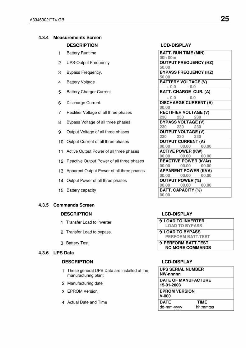
4.3.4 Measurements Screen
DESCRIPTION LCD-DISPLAY
1 Battery Runtime BATT. RUN TIME (MIN)00h 00m
2 UPS-Output Frequency OUTPUT FREQUENCY (HZ)50.00
3 Bypass Frequency. BYPASS FREQUENCY (HZ)50.00
4 Battery Voltage BATTERY VOLTAGE (V) + 0.0 - 0.0
5 Battery Charger Current BATT. CHARGE CUR. (A)
+ 0.0 - 0.0
6 Discharge Current. DISCHARGE CURRENT (A)00.00
7 Rectifier Voltage of all three phases RECTIFIER VOLTAGE (V)230 230 230
8 Bypass Voltage of all three phases BYPASS VOLTAGE (V)230 230 230
9 Output Voltage of all three phases OUTPUT VOLTAGE (V)230 230 230
10 Output Current of all three phases OUTPUT CURRENT (A)00.00 00.00 00.00
11 Active Output Power of all three phases ACTIVE POWER (KW)00.00 00.00 00.00
12 Reactive Output Power of all three phases REACTIVE POWER (kVAr)00.00 00.00 00.00
13 Apparent Output Power of all three phases APPARENT POWER (KVA)00.00 00.00 00.00
14 Output Power of all three phases OUTPUT POWER (%)00.00 00.00 00.00
15 Battery capacity BATT. CAPACITY (%)00.00
4.3.5 Commands Screen
DESCRIPTION LCD-DISPLAY
1 Transfer Load to inverter ���� LOAD TO INVERTERLOAD TO BYPASS
2 Transfer Load to bypass. ���� LOAD TO BYPASSPERFORM BATT.TEST
3 Battery Test ���� PERFORM BATT.TESTNO MORE COMMANDS
4.3.6 UPS Data
DESCRIPTION LCD-DISPLAY
1 These general UPS Data are installed at themanufacturing plant
UPS SERIAL NUMBERNW-nnnnn
2 Manufacturing dateDATE OF MANUFACTURE15-01-2003
3 EPROM Version EPROM VERSIONV-000
4 Actual Date and Time DATE TIMEdd-mm-yyyy hh:mm:ss
A3346302IT74-GB 26
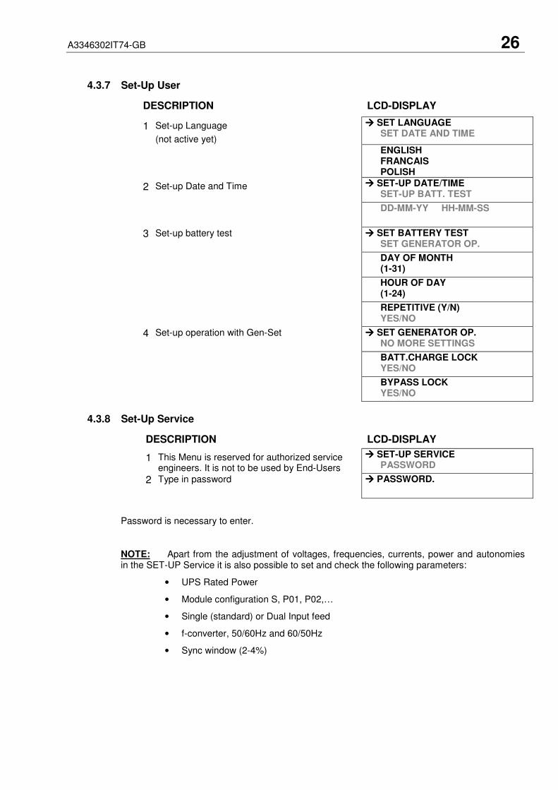
4.3.7 Set-Up User
DESCRIPTION LCD-DISPLAY
1 Set-up Language
(not active yet)
���� SET LANGUAGESET DATE AND TIME
ENGLISHFRANCAISPOLISH
2 Set-up Date and Time ���� SET-UP DATE/TIMESET-UP BATT. TEST
DD-MM-YY HH-MM-SS
3 Set-up battery test ���� SET BATTERY TESTSET GENERATOR OP.
DAY OF MONTH(1-31)
HOUR OF DAY(1-24)
REPETITIVE (Y/N)YES/NO
4 Set-up operation with Gen-Set ���� SET GENERATOR OP.NO MORE SETTINGS
BATT.CHARGE LOCKYES/NO
BYPASS LOCKYES/NO
4.3.8 Set-Up Service
DESCRIPTION LCD-DISPLAY
1 This Menu is reserved for authorized serviceengineers. It is not to be used by End-Users
���� SET-UP SERVICEPASSWORD
2 Type in password ���� PASSWORD.
Password is necessary to enter.
NOTE: Apart from the adjustment of voltages, frequencies, currents, power and autonomiesin the SET-UP Service it is also possible to set and check the following parameters:
• UPS Rated Power
• Module configuration S, P01, P02,…
• Single (standard) or Dual Input feed
• f-converter, 50/60Hz and 60/50Hz
• Sync window (2-4%)

A3346302IT74-GB 27
4.4 OPERATING MODES
4.4.1 Mode "ON LINE" (INVERTER MODE)
The ON-LINE-Mode is the UPS-Operating Mode in which the load is supplied through theRECTIFIER and INVERTER.
Using the control panel (see figure 4.1), the UPS can easily be transferred to the ON-LINE-Mode.The ON-LINE-Mode provides the highest degree of protection, especially in the event of a mainsdisturbance or failure.
This operating mode is always recommended if the critical loads (computer systems) will nottolerate any interruption of the supply (not even the shortest).
In the unlikely event of an inverter fault or overload condition the UPS will transfer the loadautomatically and without interruption to the static bypass-mains supply (transfer time = 0).
4.4.2 Mode"OFF-LINE"(ECO- or BYPASS MODE)
In the "OFF-Line Mode”, the load is supplied from the mains through the static bypass.
Using the control panel (see figure 4.1), the UPS may be easily transferred to "Bypass Mode”.
When the UPS is operating in "Bypass Mode”, the efficiency of the system is higher. In the eventof a mains failure the load will automatically be transferred from mains to inverter within 5 msec(this is valid for single and parallel systems). The battery charger remains active in the "Bypass-Mode”.
The "Bypass-Mode”, is recommended only if the loads can tolerate interruptions of 3-5 ms(transfer time from Bypass Mode to ON-LINE Mode).
In order to provide the load with maximum protection RITTAL alwaysrecommends that the load be supplied by the inverter (ON-LINE-Mode).!
LED Indicator Colour
LINE 1 Green
LINE 2 Green
BYPASS OFF
INVERTER Green
BATTERY Green
LED Indicator Colour
LINE 1 Green
LINE 2 Green
BYPASS Green
INVERTER OFF
BATTERY Green

A3346302IT74-GB 28
4.4.3 "MAINTENANCE BYPASS" - Mode
The Maintenance Bypass Mode is performed by means of the IA1 BYPASS SWITCH on the frontof the UPS:
POSITION OFSWITCH
EFFECT
ON Bypass-Switch Closed (Load supplied directly from mains)LCD-indication: “MANUAL BYP IS CLOSED” LED Indicators will indicateas shown in table below.
OFFBypass-Switch Open – Normal operating condition(Load supplied by inverter)LCD-indication “MANUAL BYP IS OPEN”LED Indicators will indicate as shown in table below.
LED Indicator ON OFF
LINE 1 Green Green
LINE 2 Green Green
BYPASS Green OFF
INVERTER RED Green
BATTERY Green Green
Before transferring the load to Maintenance Bypass (IA1) always make sure allthe UPS-modules are in the "Bypass-Mode” or “ECO-Mode”.
IF THE UPS IS OPERATING IN THE MAINTENANCE BYPASS MODE THROUGHTHE BYPASS SWITCH THE LOAD WILL NOT BE PROTECTED IN THE EVENTOF A MAINS FAILURE. IT IS THEREFORE STRONGLY RECOMMENDED TOSWITCH OVER TO THE ON-LINE MODE (INV. ON) OR BYPASS MODE (OFF-LINE MODE) AS SOON AS POSSIBLE.
4.4.4 Parallel Isolator (IA2)
Every UPS-unit (module) is provided with an output parallel isolator (IA2) which, when openedisolates the corresponding unit (module) from the PARALLEL BUS and from the LOAD. Once IA2is open there is no power coming from its inverter.
In redundant parallel configurations it is used to isolate a unit from the parallel system without theneed of transferring the load to bypass.
POSITION EFFECT
ON Normal Operation (Load supplied by UPS)
OFFUPS-Module isolated from Parallel Bus for maintenance ormodule replacement (UPS-Module not supplying load)
!
!
MAINS LOAD
MAINTENANCEBYPASS
UPS

A3346302IT74-GB 29
4.5 START-UP PROCEDURE
ALL THE OPERATIONS IN THIS SECTION MUST BE PERFORMED BYAUTHORISED ELECTRICIANS OR BY QUALIFIED INTERNAL PERSONNEL.
Situation of UPS-System before switching it on:
1. Make sure the fuses for the supply of UPS-System in the Input Distribution Board onsite are open.
2. Make sure all the input and output cabling has been performed correctly and checkthe input phase rotation.
3. Verify that all Parallel Isolator Switches IA2-1, IA2-2 and IA2-3 are open (PositionOFF).
4. Verify that the Maintenance Switch IA1 is open and in Position OFF.
5. Make sure all the battery fuses in external battery cabinets are open.
6. Bypass fuses F2 on all UPS-modules are inserted.
7. Check the DIP Switch SW1-1 position, of all Modules. If the cabinet has only oneModule and it is operating as a Single UPS (Switch in Position LOW). If it is a ParallelUPS (Switch in Position HIGH).
8. Check the Position of the DIP Switches SW1-9. This is a Single- CabinetConfiguration, and the DIP Switches SW1-9 must be set according to positionsshown in Table of Paragraph 4.2.6
Start up procedure of PMC Extended Twin:
1. Insert fuses for the supply of UPS-System in the Input Distribution- The LED-indicators LINE 1 and battery on UPS-Module is lit – green- On LCD-Display “LOAD OFF, SUPPLY FAILURE” will appear.
2. UPS-Module 1:Press both “ON/OFF” Main Buttons to switch on UPS.LCD panel must display: “LOAD DISCONNECTED PARALLEL SWITCH OPEN” andthe LED-indicator will appear as shown below:
LED Indicator Colour
LINE 1 Green
LINE 2 Green
BYPASS Green
INVERTER OFF
BATTERY Flashing Green
3. Check Command: LOAD TO INVERTERLED indicator will appear as shown below:
LED Indicator Colour
LINE 1 Green
LINE 2 Green
BYPASS OFF
INVERTER Green
BATTERY Flashing Green
4. Scroll through the menu measurement and check their correctness
5. Module 2: Repeat same procedure as for Module 1:Steps 2)-4).
6. Module 3: Repeat same procedure as for Module 1:Steps 2)-4).
7. Check battery polarity and voltage.
!

A3346302IT74-GB 30
8. If the battery polarity and voltage is correct insert external battery fuses(breakers).
9. Testing of Parallel Functions(The load fuses in output Distribution Board are still open i.e. the loads aredisconnected!). All three UPS-Modules are on INVETER MODE
10. Press simultaneously the two ON/OFF buttons on the UPS-control panel (PMD) on allthree control panels to turn the modules OFF. On the LCD’s message “LOAD OFF,SUPPLY FAILURE” will appear
11. Close Parallel Isolator IA2-1 (position ON) of Module 1, on LCD: “PARALLEL SWCLOSED” will appear.Close Parallel Isolator IA2-2 (position ON) of Module 2, on LCD: “PARALLEL SWCLOSED” will appear.Close Parallel Isolator IA2-3 (position ON) of Module 3, On LCD: “PARALLEL SWCLOSED” will appear.
12. Press simultaneously the two ON/OFF buttons on the UPS-control panel (PMD) on allthree control panels to turn the modules ON. On output Terminal Block there is nowUPS power and on all three LCD’s: “LOAD PROTECTED” will appear.
13. Load transfer to Maintenance BypassGo to Menu COMMANDS and choose command “LOAD TO BYPASS” and transferthe load to mains on control panel of any one of the three UPS-modules.Close Maintenance Bypass Switch IA1 (position ON)On LCD: “MANUAL BYP IS CLOSED” will appear and the LED-indicator will indicateas shown below:
LED Indicator Colour
LINE 1 Green
LINE 2 Green
BYPASS Green
INVERTER RED
BATTERY Green
14. Connect Load to the UPS OutputInsert fuses in output Distribution BoardVerify on control Panel that the load is on bypass
15. Open Maintenance Bypass Switch IA1On LCD: “MANUAL BYP IS OPEN” will appear followed by “LOAD NOTPROTECTED”
16. Check on LCD the Output Powers, Voltages Currents and Frequencies.
17. Load transfer to InverterGo to Menu COMMANDS and choose command “LOAD TO INVERTER” and transferthe load to inverter on control panel of any one of the three UPS-modules.On all three LCD’s: “LOAD PROTECTED” will appear followed by
18. Check the output Voltages and Currents once again.
THE LOAD IS NOW PROTECTED BY THE PMC

A3346302IT74-GB 31
4.6 SHUTDOWN PROCEDURE
ALL THE OPERATIONS IN THIS SECTION MUST BE PERFORMED BYAUTHORISED ELECTRICIANS OR BY QUALIFIED INTERNAL PERSONNEL.
The PMC may be shutdown completely if the load does not need input power for an extendedperiod of time.
It may be switched to Maintenance Bypass Mode for service or maintenance purposes, ortransferred to the OFF-LINE Mode if the load does not need the highest degree of protection.
The load may be disconnected by means of the two ON/OFF (LOAD-OFF) buttons for securityreasons.
Complete Shutdown procedure of PMC Extended Twin:
The UPS may be shut down completely if the loads do not need any powersupply. Therefore the following steps are to be performed only after the loadhas been disconnected and does not need any power supply.
PRESSING ON ALL MODULES BOTH ON/OFF BUTTONS SIMULTANEOUSLYDURING NORMAL OPERATION WILL SWITCH OFF THE UPS OUTPUT AND NOLONGER SUPPLY POWER TO THE LOAD.
1. Verify that the loads are shutdown and that there is no need for power supply to theload.
2. If the loads are all disconnected, press simultaneously both ON/OFF-Buttons on UPS-Control Panel on all three Control Panels.On the LCD: “LOAD OFF, SUPPLY FAILURE” will appear and the LED-indicator willindicate as shown below:
LED Indicator Colour
LINE 1 Green
LINE 2 OFF
BYPASS OFF
INVERTER OFF
BATTERY Green
3. Open all three Parallel Isolator Switches IA2-1, IA2-2, IA2-3.
4. Open battery fuses/breakers in external battery cabinets or racks.
5. Open the mains fuses/breaker in the building distribution panel.
AFTER SWITCHING OFF A UPS UNIT MAKE SURE THE INTERNAL DC-CAPACITORS HAVE BEEN DISCHARGED AND WAIT AT LEAST 10 MINUTES
THE PMC IS NOW VOLTAGE FREE.
!
!

A3346302IT74-GB 32
4.7 LOAD TRANSFER: FROM INVERTER OPERATION TO MAINTENANCE BYPASS
If it is necessary to perform service or maintenance on the UPS it is possible to transfer the UPSto MAINTENANCE BYPASS.
BEFORE YOU SWITCH THE MAINTENANCE BYPASS TO POSITION «ON»,MAKE SURE THAT THE LOAD HAS BEEN TRANSFERRED TO MAINS SUPPLY(OFF-LINE MODE)
ALL THE OPERATIONS IN THIS SECTION MUST BE PERFORMED BYAUTHORISED ELECTRICIANS OR BY QUALIFIED INTERNAL PERSONNEL.
Situation of UPS-System before starting the Transfer Procedure to Maintenance Bypass:
The load is protected by PMC running in normal operation. (The UPS-Module is operating oninverter).
1. Using LDC panel, select the COMMANDS menu and choose command “LOAD TOBYPASS” and transfer the load to mains on control panel of any one of the three UPS-modulesOn LCD panel “LOAD NOT PROTECTED” will appear.
2. Close Maintenance Bypass Switch IA1 (position ON).On LCD: “MANUAL BYP IS CLOSED” will appear and the mimic panel will show:
LED Indicator Colour
LINE 1 Green
LINE 2 Green
BYPASS Green
INVERTER RED
BATTERY Green
3. Press simultaneously the two ON/OFF buttons on the UPS-control panel (PMD) on allthree control panels.On the LCD’s message “LOAD OFF, SUPPLY FAILURE” will appear and the mimicpanel will show:
LED Indicator Colour
LINE 1 Green
LINE 2 OFF
BYPASS OFF
INVERTER OFF
BATTERY Flashing Green
4. Open Parallel Isolators IA2-1, IA2-2 and IA2-3.
5. Open battery fuses/breakers in the external battery cabinets or racks.
THE LOAD IS NOW SUPPLIED BY MAINS AND IS NOT PROTECTED
!
!

A3346302IT74-GB 33
4.8 LOAD TRANSFER: FROM MAINTENANCE BYPASS TO INVERTER OPERATIONS
This procedure describes the sequence of operations to be done in order to restart the UPS andrestore ON-LINE mode (Load on Inverter).
ALL THE OPERATIONS IN THIS SECTION MUST BE PERFORMED BYAUTHORISED ELECTRICIANS OR BY QUALIFIED INTERNAL PERSONNEL.
Situation of UPS-System before starting the Transfer Procedure to ON-LINE mode:
The load is supplied directly by Input Mains power and the UPS is OFF.
1. Close battery fuses/breakers in the external battery cabinets or racks.
2. On the LCD’s: “LOAD OFF, SUPPLY FAILURE” will appear and the mimic panel willshow:
LED Indicator Colour
LINE 1 Green
LINE 2 OFF
BYPASS OFF
INVERTER OFF
BATTERY Flashing/Green
3. Close Parallel Isolators IA2-1, IA2-2 and IA-3 and check message “PARALLEL SWCLOSED” on LCD of each module.
4. Press simultaneously the two ON/OFF buttons on the UPS-control panel (PMD) on allthree control panels.Unit will start-up and after about 60 seconds the mimic panel will show:
LED Indicator Colour
LINE 1 Green
LINE 2 Green
BYPASS Green
INVERTER RED
BATTERY Green
5. Make sure that the bypass LED is green, then open the Maintenance Bypass SwitchIA1 (position OFF).
6. Using LDC panel, select the COMMANDS menu and choose command “LOAD TOINVERTER”. This will transfer the LOAD to Inverter on the complete system (all units).On LCD panel “LOAD PROTECTED” will appear.
THE LOAD IS NOW SUPPLIED BY INVERTER POWER AND IS PROTECTED
!

A3346302IT74-GB 34
5 Replacement of UPS-Module
5.1 REPLACEMENT OF UPS-MODULE IN SINGLE-MODULE SYSTEMS
ALL THE OPERATIONS IN THIS SECTION MUST BE PERFORMED BYAUTHORISED ELECTRICIANS OR BY QUALIFIED INTERNAL TRAINEDPERSONNEL.BY OPENING OR REMOVING THE UPS-MODULES AND MODULE COVERS YOURUN RISK OF EXPOSURE TO DANGEROUS VOLTAGES!BEFORE REMOVING A UPS-MODULE MAKE SURE THE INTERNAL DC-CAPACITORS HAVE BEEN DISCHARGED FOR AT LEAST 2 MINUTES.DO NOT EVER LEAVE THE UPS-MODULE COMPARTMENT WITHOUT ANAPPROPRIATE PROTECTION COVERRITTAL WILL NOT TAKE RESPONSIBILITY OR BE LIABLE FOR PERSONNELINJURIES OR MATERIAL DAMAGES CAUSED BY IMPROPER MANIPULATIONOF THE UPS, OR BY INCORRECT CABLING. THE PROPER INSTALLATION ANDUSAGE INSTRUCTIONS OF THE UPS ARE DESCRIBED WITHIN THIS MANUALAND MUST BE STRICTLY ADHERED TO.
5.1.1 How to Extract a UPS-Module in SINGLE MODULE Systems
If your PMC Extended Twin consists of only one single UPS-Module then perform followingsteps to extract the module:
1. Reset the Alarm on faulty Module. The audible noise will stop.If the Alarm condition persists (the LED-Indicator ALARM will remain red) it meansthat there is a fault in the UPS-Module.
2. If the load is supplied by the mains in Bypass-Mode (Eco-Mode) the MaintenanceBypass (IA1) may be closed by turning it to position “ON”.NOTE: If the load is on inverter then before closing the Maintenance Bypass IA1,transfer load to bypass by means of the command “LOAD TO BYPASS” in submenuCOMMANDS. On LCD: “LOAD NOT PROTECTED” will appear.
3. Close Maintenance Bypass Switch IA1 (position ON)On LCD: “MANUAL BYP IS CLOSED” will appear and the LED-indicator will indicateas shown below:
LED Indicator Colour
LINE 1 Green
LINE 2 Green
BYPASS Green
INVERTER RED
BATTERY Green
The load is now directly supplied by mains and is not protected
4. Open the Parallel Isolator Switch IA2 (switch to position “OFF”) of the faulty UPS-Module. The UPS-Module is now disconnected from output;
5. Press both ON/OFF Buttons on UPS-Module simultaneously;
6. Open battery fuses/breakers in external battery cabinet or rack;
7. Disconnect cables from connectors JD1, JD2, JD7, JD4 and SNMP network cable.
8. Unscrew the four screws on the front side of the module that are fixing it to the UPS-frame;
!

A3346302IT74-GB 35
9. Pull Module only partly horizontally by means of the 2 black handles until the rearconnectors are disconnected.
ATTENTION: BEFORE DRAWING THE UPS-MODULE COMPLETELY OUT, WAIT 2 MINUTESUNTIL THE INTERNAL DC-CAPACITORS ARE DISCHARGED.
10. Draw UPS-Module by pulling it out horizontally:NOTE: Two persons are needed to pull out the module from the UPS-Frame. Theweight of a 40 kVA-module is 56kg (the weight of 10 kVA-module is 52kg)
11. Insert new UPS-Module or cover the opening (UPS-Module Compartment) withappropriate protection cover immediately and fix with four screws.
WHILE THE UPS IS OPERATING IN THE MAINTENANCE BYPASS-MODE THE LOAD IS NOTPROTECTED AND IN THE EVENT OF A MAINS FAILURE THE LOAD SUPPLY WILL BEINTERRUPTED AND THE LOAD WILL CRASH.
5.1.2 How to Fit Back a UPS-Module in SINGLE-MODULE-Systems
ALL THE OPERATIONS IN THIS SECTION MUST BE PERFORMED BYAUTHORISED ELECTRICIANS OR BY QUALIFIED INTERNAL TRAINEDPERSONNEL.BY OPENING OR REMOVING THE UPS-MODULES AND MODULE COVERS YOURUN RISK OF EXPOSURE TO DANGEROUS VOLTAGES!DO NOT EVER LEAVE THE UPS-MODULE COMPARTMENT WITHOUT ANAPPROPRIATE PROTECTION COVERRITTAL WILL NOT TAKE RESPONSIBILITY OR BE LIABLE FOR PERSONNELINJURIES OR MATERIAL DAMAGES CAUSED BY IMPROPER MANIPULATIONOF THE UPS, OR BY INCORRECT CABLING. THE PROPER INSTALLATION ANDUSAGE INSTRUCTIONS OF THE UPS ARE DESCRIBED WITHIN THIS MANUALAND MUST BE STRICTLY ADHERED TO.
If your PMC Extended Twin consists of only one single UPS-Module then perform followingsteps to fit back the new module:
1. Remove UPS-Module compartment protection cover by unscrewing four screws onthe front.
2. Slide two thirds of UPS-Module into dedicated UPS-compartment (make sure not toplug the UPS-Module into the rear connector).Connect Control Panel cable to connector JD7.Push UPS-module to its final position and push strongly to assure good contact on therear plugs.NOTE: Two persons are needed to carry and push the module to its final position inUPS-frame. The weight of 40 kVA-Module is 56kg (the weight of 10 kVA-module is52kg)
3. Tighten the four screws on the front of module;
4. Reconnect cables on connectors JD1, JD2, JD4 and SNMP network cable.
5. Check if the LED LINE1 and battery is green. If yes, mains voltage is OK;On the LCD: “LOAD OFF, SUPPLY FAILURE” will appear and the LED-indicator willindicate as shown below:
LED Indicator Colour
LINE 1 Green
LINE 2 OFF
BYPASS OFF
INVERTER OFF
BATTERY Flashing Green
!
!
!
A3346302IT74-GB 36
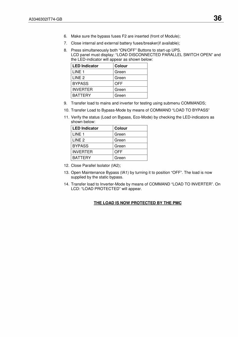
6. Make sure the bypass fuses F2 are inserted (front of Module);
7. Close internal and external battery fuses/breaker(if available);
8. Press simultaneously both “ON/OFF” Buttons to start-up UPS.LCD panel must display: “LOAD DISCONNECTED PARALLEL SWITCH OPEN” andthe LED-indicator will appear as shown below:
LED Indicator Colour
LINE 1 Green
LINE 2 Green
BYPASS OFF
INVERTER Green
BATTERY Green
9. Transfer load to mains and inverter for testing using submenu COMMANDS;
10. Transfer Load to Bypass-Mode by means of COMMAND “LOAD TO BYPASS”
11. Verify the status (Load on Bypass, Eco-Mode) by checking the LED-indicators asshown below:
LED Indicator Colour
LINE 1 Green
LINE 2 Green
BYPASS Green
INVERTER OFF
BATTERY Green
12. Close Parallel Isolator (IA2);
13. Open Maintenance Bypass (IA1) by turning it to position “OFF”. The load is nowsupplied by the static bypass.
14. Transfer load to Inverter-Mode by means of COMMAND “LOAD TO INVERTER”. OnLCD: “LOAD PROTECTED” will appear.
THE LOAD IS NOW PROTECTED BY THE PMC

A3346302IT74-GB 37
5.2 REPLACEMENT OF UPS-MODULE IN REDUNDANT MULTI-MODULE SYSTEM
ALL THE OPERATIONS IN THIS SECTION MUST BE PERFORMED BYAUTHORISED ELECTRICIANS OR BY QUALIFIED INTERNAL TRAINEDPERSONNEL.BY OPENING OR REMOVING THE UPS-MODULES AND MODULE COVERS YOURUN RISK OF EXPOSURE TO DANGEROUS VOLTAGES!BEFORE REMOVING A UPS-MODULE MAKE SURE THE INTERNAL DC-CAPACITORS HAVE BEEN DISCHARGED FOR AT LEAST 2 MINUTES.DO NOT EVER LEAVE THE UPS-MODULE COMPARTMENT WITHOUT ANAPPROPRIATE PROTECTION COVERRITTAL WILL NOT TAKE RESPONSIBILITY OR BE LIABLE FOR PERSONNELINJURIES OR MATERIAL DAMAGES CAUSED BY IMPROPER MANIPULATIONOF THE UPS, OR BY INCORRECT CABLING. THE PROPER INSTALLATION ANDUSAGE INSTRUCTIONS OF THE UPS ARE DESCRIBED WITHIN THIS MANUALAND MUST BE STRICTLY ADHERED TO.
5.2.1 How to Extract a Module in Redundant Multi-Module System
If in a redundant parallel system a UPS-module is faulty, the load will continue to be protected bythe operating modules On-Line-Mode (Inverter-Mode) and the faulty Module may be replacedwithout having to transfer the load to bypass!
To extract the faulty module from the UPS-Frame in a Redundant Multi- Module Configurationproceed as follows:
1. Identify the faulty Module with the Alarm condition and RESET the Alarm. The audiblenoise will stop. If the Alarm conditions persists (the LED-Indicator ALARM is red) thereis a fault in the UPS-Module.
2. Verify that load is supplied by inverter of the other modules running by checking theLCD indication LOAD PROTECTED. Verify load measures on the operating modules.
3. Turn the faulty module OFF by pressing simultaneously both “ON/OFF” buttons.On the LCD: “LOAD OFF, SUPPLY FAILURE” should appear and the LED-indicatorwill indicate as shown below:
LED Indicator Colour
LINE 1 Green
LINE 2 OFF
BYPASS OFF
INVERTER OFF
BATTERY Flashing Green
4. Open the corresponding Parallel Isolator Switch IA2. LCD panel must show:PARALLEL SW OPEN.
5. Remove the 4 fixation screws and slide out the UPS-Module (10cm) paying particularattention to the cable connected to JD4. This operation will disconnect module by thepower connection located on the back of the cabin.
6. With the module OFF, disconnect any connected cable as JD7, JD1 and JD2, and anynetwork cable from the SNMP adapter.
7. Pull the module out.
ATTENTION: BEFORE DRAWING THE UPS-MODULE COMPLETELY OUT,WAIT 2 MINUTES UNTIL THE INTERNAL DC-CAPACITORS ARE DISCHARGED.
NOTE: Two persons are needed to carry and push the module to its final position in UPS-frame. The weight of 40 kVA-Module is 56kg (the weight of 10 kVA-module is 52kg).
8. Screw the protection cover on the empty area left empty by the module with the 4fixation screws.
!

A3346302IT74-GB 38
5.2.2 How to insert a module in a Redundant Multi Module System
In a Redundant Parallel system one module can be re-introduced on its original location withoutaffecting normal system operation. Load will be protected by the other modules running ON-LINE.
Module must be previously set according to system personalization. Please make sure with yournearest service centre for correct settings.
1. Remove the protection cover by unscrewing the 4 fixation screws on the front.
2. Lift the module to its destination position. See above note concerning weights.
3. Slide two thirds of UPS module into dedicated compartment (make sure not to plug theUPS-Module into the rear connector). Connect Control Panel cable to connector JD7.Push UPS-module to its final position and push strongly to assure good contact on therear plugs. Tighten the four screws on the front of module;
4. Reconnect cables on connectors JD1, JD2, JD4 and SNMP network cable;
5. Check if LED LINE1 and battery is green. If yes, mains voltage is OK;On the LCD: “LOAD OFF, SUPPLY FAILURE” will appear and the LED-indicator willindicate as shown below:
LED Indicator Colour
LINE 1 Green
LINE 2 OFF
BYPASS OFF
INVERTER OFF
BATTERY Flashing Green
6. Make sure the bypass fuse F2 is inserted (front of Module);
7. Close external battery fuses/breaker of the new Module
8. Press both “ON/OFF” Buttons simultaneously to start-up UPS.
9. Wait 60 seconds, LCD panel must display: “LOAD DISCONNECTED PARALLELSWITCH OPEN” and the LED-indicator will appear as shown below:
LED Indicator Colour
LINE 1 Green
LINE 2 Green
BYPASS Green
INVERTER OFF
BATTERY Flashing/Green
10. Transfer load to Inverter-Mode by means of COMMAND “LOAD TO INVERTER” ofthe control panel. LED-indicator will appear as shown below:
LED Indicator Colour
LINE 1 Green
LINE 2 Green
BYPASS OFF
INVERTER Green
BATTERY Green
11. Stop the module by pressing simultaneously both “ON/OFF” buttons.
12. Close the Parallel Isolator Switch IA2 corresponding to the module.LCD panel must show the message PARALLEL SW CLOSED.
13. Press simultaneously both “ON/OFF” buttons.Module will restart automatically connecting load to inverter and run in parallel withother ON LINE modules. LCD panel must show LOAD PROTECTED indication.
THE LOAD IS NOW PROTECTED BY THE PMC

A3346302IT74-GB 39
5.3 REPLACEMENT OF A MODULE IN CAPACITY MULTI-MODULE SYSTEM
ALL THE OPERATIONS IN THIS SECTION MUST BE PERFORMED BYAUTHORISED ELECTRICIANS OR BY QUALIFIED INTERNAL TRAINEDPERSONNEL.BY OPENING OR REMOVING THE UPS-MODULES AND MODULE COVERS YOURUN RISK OF EXPOSURE TO DANGEROUS VOLTAGES!BEFORE REMOVING A UPS-MODULE MAKE SURE THE INTERNAL DC-CAPACITORS HAVE BEEN DISCHARGED FOR AT LEAST 2 MINUTES.DO NOT EVER LEAVE THE UPS-MODULE COMPARTMENT WITHOUT ANAPPROPRIATE PROTECTION COVERRITTAL WILL NOT TAKE RESPONSIBILITY OR BE LIABLE FOR PERSONNELINJURIES OR MATERIAL DAMAGES CAUSED BY IMPROPER MANIPULATIONOF THE UPS, OR BY INCORRECT CABLING. THE PROPER INSTALLATION ANDUSAGE INSTRUCTIONS OF THE UPS ARE DESCRIBED WITHIN THIS MANUALAND MUST BE STRICTLY ADHERED TO.
5.3.1 How to Extract a Module in a Capacity Multi-Module System
If in capacity parallel system a UPS-Module experiences a fault and there is not enough capacityleft to protect the load by the remaining operating UPS-Modules, the load will automatically betransferred to bypass (Bypass-Mode or Eco-Mode) and will continue to be supplied by the mainspower supply.
To extract the faulty module from the UPS-Frame in a Capacity Multi-Module System proceedas follows:
1. Identify the faulty Module with the Alarm condition and RESET the Alarm. The audiblenoise will stop. If the Alarm conditions persists (the LED-Indicator ALARM is red) thereis a fault in the UPS-Module.
2. Verify that the load is on Bypass and is supplied by the mains power (Bypass-Mode orEco-Mode) on all three UPS-Modules; in the majority of the events the LED-indicatorson Control Panel of the Faulty Module will show:
LED Indicator Colour
LINE 1 Green
LINE 2 Green
BYPASS Green
INVERTER RED
BATTERY Green
3. Whereas the LED-indicators on the Control Panels of the other two OperatingModules will show
LED Indicator Colour
LINE 1 Green
LINE 2 Green
BYPASS Green
INVERTER OFF
BATTERY Green
4. Close Maintenance Bypass Switch IA1 (position ON)
!

A3346302IT74-GB 40
5. On LCD: “MANUAL BYP IS CLOSED” will appear and the LED-indicator will indicateas shown below:
LED Indicator Colour
LINE 1 Green
LINE 2 Green
BYPASS Green
INVERTER RED
BATTERY Green
The load is now directly supplied by mains and is not protected
6. Open the Parallel Isolator Switch IA2 (switch to position “OFF”) of UPS-module to bereplaced. The UPS-module is now disconnected from the output;
7. Press both ON/OFF Buttons on UPS-Module simultaneously;
8. Open corresponding battery fuses;
9. Remove the 4 fixation screws and slide out the UPS-Module (10cm) paying particularattention to the cable connected to JD4. This operation will disconnect module by thepower connection located on the back of the cabin.
10. Disconnect cables from connectors JD1, JD2, JD7, JD4 and SNMP network cable;
ATTENTION: BEFORE DRAWING THE UPS-MODULE COMPLETELY OUT,WAIT 2 MINUTES UNTIL THE INTERNAL DC-CAPACITORS ARE DISCHARGED.
11. Draw UPS-Module by pulling it out horizontally:NOTE: Two persons are needed to pull out the module from the UPS-Frame. Theweight of a 40 kVA-module is 56kg (10 kVA-module 52kg).
12. Insert new UPS-Module or cover the opening (UPS-Module Compartment) withappropriate protection cover immediately and fix with four screws.
WHILE THE UPS IS OPERATING IN THE MAINTENANCE BYPASS-MODE THELOAD IS NOT PROTECTED AND IN THE EVENT OF A MAINS FAILURE THELOAD SUPPLY WILL BE INTERRUPTED AND THE LOAD WILL CRASH.
5.3.2 How to Fit Back a Module in a Capacity Multi-Module System
To replace a Faulty Module in a Capacity Multi-Module System perform following steps:
1. Remove UPS-Module compartment protection cover by unscrewing four screws onthe front.
2. Slide two thirds of UPS-Module into dedicated UPS-compartment (make sure not toplug the UPS-Module into the rear connector).Connect Control Panel cable to connector JD7.Push UPS-module to its final position and push strongly to assure good contact on therear plugs.
NOTE: Two persons are needed to carry and push the module to its final position inUPS-frame. The weight of 40 kVA-Module is 56kg (the weight of 10 kVA-module is52kg)
3. Tighten the four screws on the front of module;
4. Reconnect cables on connectors JD1, JD2, JD4 and SNMP network cable;
!
!

A3346302IT74-GB 41
5. Check if LED LINE1 and battery are green.On the LCD: “LOAD OFF, SUPPLY FAILURE” will appear and the LED-indicator willindicate as shown below:
LED Indicator Colour
LINE 1 Green
LINE 2 OFF
BYPASS OFF
INVERTER OFF
BATTERY Flashing Green
6. Make sure the bypass fuse F2 is inserted (front of Module);
7. Close external battery fuses/breaker of the new Module;
8. Press both “ON/OFF” Buttons simultaneously to start-up UPS.LCD panel must display: “LOAD DISCONNECTED PARALLEL SWITCH OPEN” andthe LED-indicator will appear as shown below:
LED Indicator Colour
LINE 1 Green
LINE 2 Green
BYPASS Green
INVERTER OFF
BATTERY Green
9. Transfer load to mains and inverter for testing using submenu COMMANDS
10. Transfer Load to Bypass-Mode by means of COMMAND “LOAD TO BYPASS
11. Verify the status LOAD ON BYPASS
LED Indicator Colour
LINE 1 Green
LINE 2 Green
BYPASS Green
INVERTER OFF
BATTERY Green
12. Verify that the remaining UPS-Modules are also on Bypass;
13. If all three UPS-Modules are on Bypass, Close Parallel Isolator Switch IA2 of NewModule (position ON); on LCD should appear “PARALLEL SW IS CLOSED”.
14. Open Maintenance Bypass (IA1) by turning it to position “OFF”. The load is nowsupplied by the static bypass of all three Modules. Check LED-indicators on controlpanels.
15. Transfer load to Inverter-Mode by means of COMMAND “LOAD TO INVERTER” onany one of three control panels. On LCD: “LOAD PROTECTED” will appear and theLED-indicator will indicate as shown below:
LED Indicator Colour
LINE 1 Green
LINE 2 Green
BYPASS OFF
INVERTER Green
BATTERY Green
THE LOAD IS NOW PROTECTED BY THE PMC
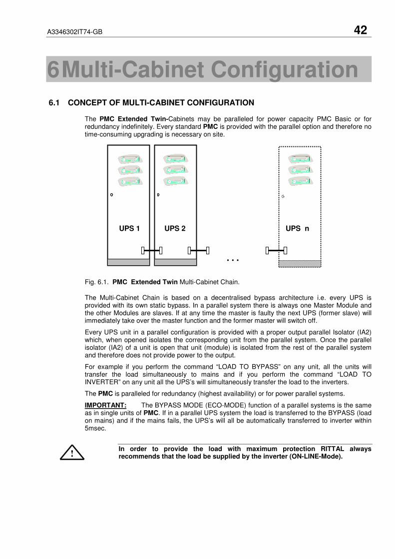
A3346302IT74-GB 42
6 Multi-Cabinet Configuration
6.1 CONCEPT OF MULTI-CABINET CONFIGURATION
The PMC Extended Twin-Cabinets may be paralleled for power capacity PMC Basic or forredundancy indefinitely. Every standard PMC is provided with the parallel option and therefore notime-consuming upgrading is necessary on site.
UPS 1 UPS 2 UPS n
Fig. 6.1. PMC Extended Twin Multi-Cabinet Chain.
The Multi-Cabinet Chain is based on a decentralised bypass architecture i.e. every UPS isprovided with its own static bypass. In a parallel system there is always one Master Module andthe other Modules are slaves. If at any time the master is faulty the next UPS (former slave) willimmediately take over the master function and the former master will switch off.
Every UPS unit in a parallel configuration is provided with a proper output parallel Isolator (IA2)which, when opened isolates the corresponding unit from the parallel system. Once the parallelisolator (IA2) of a unit is open that unit (module) is isolated from the rest of the parallel systemand therefore does not provide power to the output.
For example if you perform the command “LOAD TO BYPASS” on any unit, all the units willtransfer the load simultaneously to mains and if you perform the command “LOAD TOINVERTER” on any unit all the UPS’s will simultaneously transfer the load to the inverters.
The PMC is paralleled for redundancy (highest availability) or for power parallel systems.
IMPORTANT: The BYPASS MODE (ECO-MODE) function of a parallel systems is the sameas in single units of PMC. If in a parallel UPS system the load is transferred to the BYPASS (loadon mains) and if the mains fails, the UPS’s will all be automatically transferred to inverter within5msec.
In order to provide the load with maximum protection RITTAL alwaysrecommends that the load be supplied by the inverter (ON-LINE-Mode).!
…
…
A3346302IT74-GB 43
6.2 INSTALLATION INSTRUCTIONS
6.2.1 Introduction
ELECTRICIANS OR BY QUALIFIED INTERNAL TRAINED PERSONNEL.
BY OPENING OR REMOVING THE UPS-MODULES AND MODULE COVERSYOU RUN RISK OF EXPOSURE TO DANGEROUS VOLTAGES!
BEFORE REMOVING A UPS-MODULE MAKE SURE THE INTERNAL DC-CAPACITORS HAVE BEEN DISCHARGED FOR AT LEAST 2 MINUTES.
DO NOT EVER LEAVE THE UPS-MODULE COMPARTMENT WITHOUT ANAPPROPRIATE PROTECTION COVER.
RITTAL WILL NOT TAKE RESPONSIBILITY OR BE LIABLE FOR PERSONNELINJURIES OR MATERIAL DAMAGES CAUSED BY IMPROPER MANIPULATIONOF THE UPS, OR BY INCORRECT CABLING. THE PROPER INSTALLATION ANDUSAGE INSTRUCTIONS OF THE UPS ARE DESCRIBED WITHIN THIS MANUALAND MUST BE STRICTLY ADHERED TO.
DO NOT ATTEMPT TO COMMISSION A PARALLEL CABINETS SYSTEMWITHOUT CAREFULLY READING THIS USER MANUAL (SEE ALSOCHAPTERS 3 AND 4
NOTE: IN ORDER TO ACHIEVE EQUAL LOAD SHARING BETWEEN THE UPS-CABINETS, THEINPUT CABLE LENGTHS FROM THE INPUT DISTRIBUTION BOARD TO THE UPS AND FROM THEOUTPUT CABLE TO THE OUTPUT DISTRIBUTION BOARD SHOULD BE THE SAME RESPECTIVELY.WHEN CABLING THE UPS’S BEWARE TO CONNECT INPUT AND OUTPUT WIRES TO THECORRESPONDING TERMINALS, RESPECTING THE SAME PHASE SEQUENCE ON ALL UPSCABINETS. EXAMPLE: PHASE1 UPS1 = PHASE1 UPS2 = …… = PHASE1 UPS n
WHEN CABLING THE UPS’s MAKE SURE THAT THE UPS’s ARECOMPLETELY VOLTAGE FREE. CHECK THAT THE MAINTENANCEBYPASSES (IA1) AND ALL PARALLEL ISOLATOR (IA2) ARE OPEN (“OFF”) ONALL CABINETS.
6.2.2 Paralleling of UPS-Cabinets
6.2.2.1 Connection of Parallel Communication Cables (BUS-lines)
For the correct performance of different parallel functions and operations the parallel unitscommunicate continuously between each other. This is achieved by means of the so-calledcommunication BUS-Lines.
After terminating the input and output cabling of each single UPS, it is necessary to connect theunits together to form the parallel system. For this purpose a communication BUS line isconnected sequentially between the units. Connect communication BUS lines according to Figure6.2.
NOTE: CONNECT THE BUS CABLES ONLY WITH SWITCHED OFF UPS AND OPENEDPARALLEL ISOLATORS IA2. RESPECT THE FOLLOWING CONNECTION SEQUENCES.
1. Fit the Parallel Adapter over the Connector JD8 on all UPS-cabinets
2. Set DIP Switch SW2-2 on each Parallel Adapter depending on the UPS Cabinet in theparallel cabinet configuration (see page 45)
3. Connect PORT JD6 on Parallel Adapter of UPS-Cabinet 1and PORT JD5 of ParallelAdapter of UPS-Cabinet 2 with the corresponding BUS-Cable;
4. Connect PORT JD6 on Parallel Adapter of UPS-Cabinet 2 and PORT JD5 of UPS-Cabinet 3 with the corresponding BUS-Cable
5. Continue in the same manner for the remaining UPS-Cabinets.
!
!
!

A3346302IT74-GB 44
Figure 6.2.Connection of the Bus Lines when paralleling UPS-Cabinets by means of ParallelAdapters.
6.2.2.2 Parallel Adapater and DIP-Switch SW2-2
If the UPS-CABINETS are paralleled the Parallel Adapter will be placed on the Connector JD8 onthe distribution panel and the communications cables between the cabinets will be connectedthrough the connectors JD5 and JD6, as we are doing now.
NOTE: set the Switch SW2-2 correctly according to the corresponding cabinet configuration.
6.2.3 DIP-Switch SW1-1 and SW1-9 Settings
Before starting up the parallel system it is necessary to set the DIP Switches SW1-1 and SW1-9to their correct positions.
DIP Switch SW1-1
The DIP Switch SW1-1 is located on every UPS-Module and serves to define if the UPS-Moduleis a single or parallel Module.
SW1-1 has two positions:
HIGH = Parallel (the Module is in a parallel system)
LOW = Single (the Module is a single UPS)
In the case of parallel cabinet configurations the SW1-1 on all Modules is always in position HIGH= Parallel.
SingleUnit First Unit Middle Unit Last UnitSW 1 ON OFF OFF ONSW 2 ON ON OFF OFF
SW1-1 Module Type
HIGH Parallel Module
LOW Single Module
UPS-Cabinet 1 UPS-Cabinet 2 UPS-Cabinet n-1 UPS-Cabinet n
Parallel Adapter
JD6 JD5
Master-SlaveInput
Master-SlaveOutput SW2-2
Parallel Adapter
JD6 JD5
Master-SlaveInput
Master-SlaveOutput SW2-2
Parallel Adapter
JD6 JD5
Master-SlaveInput
Master-SlaveOutput SW2-2
Parallel Adapter
JD6 JD5
Master-SlaveInput
Master-SlaveOutput SW2-2
ParallelAdapter
JD 5
SW2-2
JJD6
JD8
A3346302IT74-GB 45
DIP Switch SW1-9
The DIP Switch SW1-9 is located on every Cabinet (PMC Extended Twin) and not on Modules.With this switch it is possible to determine the “position of an PMC Extended Twin-Cabinet” ina Multi-Cabinet Chain. Define each PMC Extended Twin-Cabinet in a Multi-Cabinet Chain as:
1. The “First”,
2. The “Middle” (there may be more than one) and
3. The “Last”
Cabinet in the Multi-Cabinet Chain by setting the DIP Switch SW1-9 on each cabinet according tothe Table below:
SW1-9 SingleCabinet
FirstCabinet
MiddleCabinet
LastCabinet
1 ON ON OFF ON
2 ON ON OFF ON
3 ON ON OFF ON
4 ON ON OFF ON
5 ON ON OFF ON
6 ON ON OFF ON
7 ON ON OFF ON
8 ON ON OFF OFF
9 ON OFF OFF ON
After having set the SW1-1 on all UPS-Modules and SW1-9 on all the PMC Extended Twin-Cabinets correctly the UPS’s may be commissioned
6.2.4 ON/OFF – Main Buttons
The ON/OFF-Buttons serve to shutdown the UPS-system for service or maintenance or foremergency reasons.
IF BOTH ON/OFF-BUTTONS ARE PRESSED ON THE UPS-Module IN A MULTI-Module SYSTEM ONLY THAT PARTICULAR UPS-Module WILL SHUTDOWN.TO SHUTDOWN THE COMPLETE SYSTEM PRESS BOTH ON/OFF-BUTTONSON EVERY UPS-MODULE OF A MULTI-MODULE SYSTEM .
6.2.5 Parallel Isolator (IA2)
Every UPS-unit is provided with a parallel isolator IA2. The parallel isolator is an importantelement of the UPS-unit, that allows the isolation of a unit from the parallel system without theneed to transfer the load to bypass.
IA2 OPEN: THE CORRESPONDING UPS-MODULE IS ISOLATED FROM THEOUTPUT. THERE IS NO COMMUNICATION BETWEEN THE ISOLATED UNIT ANDTHE REST OF THE PARALLEL SYSTEM. THE ISOLATED UPS-MODULE MAY BEREPLACED WITHOUT COMPROMISING THE REST OF THE SYSTEM.IA2 CLOSED: THE CORRESPONDING UPS IS BEING ADDED TO THE REST OFTHE PARALLEL SYSTEM.IMPORTANT: BEFORE CLOSING THE IA2 OF A UPS-MODULE BE SURE THATTHE STATUS OF THAT UPS-MODULE IS THE SAME AS OF THE REST OF THEOPERATING UPS-MODULE WITH CLOSED IA2. EXAMPLE: IF ALL UPS’s WITHCLOSED IA2 ARE ON INVERTER, MAKE SURE THAT THE UNIT ON WHICHISOLATOR IA2 IS BEING CLOSED IS ALSO ON INVERTER.
6.2.6 Maintenance Bypass (IA1)
There are two types of Parallel System Configurations: redundant and capacity parallel systems(see Chapter 5).
!
!

A3346302IT74-GB 46
6.2.6.1 Redundant Parallel Configuration
In a redundant parallel system a UPS-module may easily be isolated from the parallel system byopening the respective isolator (IA2). It is now possible to operate or shut down this unit withoutinfluencing the rest of the parallel system. The rest of the parallel system will continue to protectthe load. The isolated UPS-Module may be replaced without the need of transferring the load tobypass by means of the Maintenance Bypass (IA1).
6.2.6.2 Capacity Parallel Configuration
In the event of a fault in one of the UPS-Modules in a capacity parallel system the load willautomatically be transferred to static bypass (mains). In order to replace the faulty module theload must be transferred to mains by means of Maintenance Bypass (IA1).
6.2.7 ECO-MODE (BYPASS MODE) in Parallel Systems
The Eco-Mode function in a Parallel System is the same as in Single Systems. If in a PMCParallel System the load is supplied by the mains(load on mains) and in the event of mainsfailure, all UPS’s will automatically transfer the load back to the inverters with 5msec.
In order to provide the load with maximum protection RITTAL alwaysrecommends that the load be supplied by the inverter (ON-LINE-Mode).
6.3 COMMISSIONING OF MULTI-CABINET CONFIGURATION
ALL THE OPERATIONS IN THIS SECTION MUST BE PERFORMED BYAUTHORISED ELECTRICIANS OR BY QUALIFIED INTERNAL TRAINEDPERSONNEL.BY OPENING OR REMOVING THE UPS-MODULES AND MODULE COVERS YOURUN RISK OF EXPOSURE TO DANGEROUS VOLTAGES!BEFORE REMOVING A UPS-MODULE MAKE SURE THE INTERNAL DC-CAPACITORS HAVE BEEN DISCHARGED FOR AT LEAST 2 MINUTES.DO NOT EVER LEAVE THE UPS-MODULE COMPARTMENT WITHOUT ANAPPROPRIATE PROTECTION COVER.RITTAL WILL NOT TAKE RESPONSIBILITY OR BE LIABLE FOR PERSONNELINJURIES OR MATERIAL DAMAGES CAUSED BY IMPROPER MANIPULATION OFTHE UPS, OR BY INCORRECT CABLING. THE PROPER INSTALLATION ANDUSAGE INSTRUCTIONS OF THE UPS ARE DESCRIBED WITHIN THIS MANUALAND MUST BE STRICTLY ADHERED TO.
6.3.1 Start-up of a Multi-Cabinet Configuration
Before starting up a Multi-Cabinet Configuration verify that:
1. All the input and output cabling has been performed correctly according to Chapter 3of this User Manual;
2. The parallel communication cables have been connected correctly according toParagraph 6.2.2 of Chapter 6;
3. All the DIP Switches for the Modules and PMC Extended Twin-Cabinets been setcorrectly according to Paragraph 6.2.3 of Chapter 6;
4. All the external battery cabinets/racks have been connected correctly;
The start-up of a Multi-Cabinet Configuration may be performed in analogy to the start-upprocedures for a single PMC Twin-Cabinet described in Paragraph 4.5 of Chapter 4.
6.3.2 Shutdown of Multi-Cabinet Configuration
Before shutting-down of a Multi-Cabinet Configuration make sure that the loads do need powerprotection and that they are disconnected.
!
!

A3346302IT74-GB 47
The UPS may be shut down completely if the loads do not need any powersupply. Therefore the steps in this Paragraph are to be performed only afterthe load has been disconnected and does not need any power supply.
To perform a complete shutdown of a Multi-Cabinet Configuration proceed in analogy to theshutdown procedures described in Paragraph 4.6 of Chapter 4.
6.3.3 Replacement of a Faulty UPS-Module in a Multi-Cabinet Configuration
If in a Multi-Cabinet Configuration a UPS-Module fails proceed in replacing the UPS-Module inanalogy with the replacement procedures described in Chapter 5 of this User Manual.
!

A3346302IT74-GB 48
7 Maintenance
7.1 INTRODUCTION
ALL THE OPERATIONS IN THIS SECTION MUST BE PERFORMED BYAUTHORISED ELECTRICIANS OR BY QUALIFIED INTERNAL PERSONNEL.
To ensure an optimum operation of the PMC and a continuous and efficient protection of theconnected load it is recommended to check the batteries every 6 months, depending on theambiance temperature.
7.2 USER RESPONSIBILITIES
There are no user serviceable parts contained within the UPS so the maintenance responsibilitiesof the user are minimal. To maximise the useful working life and reliability of the UPS and itsbatteries, the environment in which the UPS operates should be kept cool, dry, dust and vibrationfree. The batteries should be hold fully charged.
7.3 ROUTINE MAINTENANCE
The UPS is designed to receive regular preventative maintenance inspections. Thesepreventative maintenance inspections are essential to ensure that both the useful working life andthe reliability of the UPS are maximised. When the UPS is commissioned, the commissioningfield service engineer will attach a service record book to the front of the UPS and this will beused to record the full service history of the UPS.
Preventative maintenance inspections involve working inside the UPS, which contains hazardousAC and DC voltages. Only RITTAL trained or agreed service personnel and authorised fieldservice engineers are fully aware of all of the hazardous areas within the UPS.
During a preventative maintenance inspection the field service engineer will carry out thefollowing checks:
• Site/environment conditions;
• Integrity of electrical installation;
• Cooling airflow;
• Rectifier operation and calibration;
• Inverter operation and calibration;
• Static switch operation;
• Battery status;
• Load characteristics;
• Integrity of alarm and monitoring systems;
• Operation of all installed options;
7.4 BATTERY TEST
The battery test takes approx. 3 minutes and should be performed only if:
• there are no alarm conditions;
• the battery is fully charged;
• mains is present.
The battery testing can be carried out independently of the operation mode (OFF-LINE or ON-LINE) and whether or not the load is connected.
The battery test procedure can be performed from the UPS front panel. See “Operation” Chapter 4.
!

A3346302IT74-GB 49
8 Troubleshooting
8.1 ALARMS
In the event of an alarm condition the red LED-Indicator “Alarm” and the audible alarm will turnon.
In this case proceed as follows:
1. Silence the audible alarm by pressing the button "Reset".2. Identify the cause of the alarm condition by means of the EVENT LOG in the MAIN
menu.3. In case of doubts please contact the nearest Service centre.4. Fault identification and rectification information is given on the following pages.
8.2 MENU, COMMANDS, EVENT LOG AND MEASUREMENTS
In Chapter 4 there is a detailed description of the Menu, Commands, Event Log andMeasurements that can be operated and displayed on the LCD. The List of Alarms andMessages are shown in the Annexe.
8.3 FAULT IDENTIFICATION AND RECTIFICATION
The major alarm conditions that will be encountered are:
Alarm Condition Meaning Suggested Solution
UPS FAULTThere is a fault in the UPS andtherefore normal operation cannotbe guaranteed
Call the authorised service centre forassistance
MAINS BYP/RECTFAULT
Mains power supply is outsideprescribed tolerance
The input power to UPS is too low or missing.If site power appears to be OK, check the inputcircuit breakers etc. supplying the UPS
OUTPUT SHORTThere is a short circuit at the outputof UPS (on load side)
Check all output connections and repair asrequired.
OVERLOAD Load exceeds the UPS rated power
Identify which piece of equipment is causingthe overload and remove it from the UPS.Do not connect laser printers, photocopiers,electric heaters, kettles etc. to the UPS
OVERTEMPERATUREUPS temperature has exceeded theallowed value
Check the ambient temperature of the UPS isless than 30° C.If the ambient temperature is normal call theauthorised service centre for assistance.
BATTERY CHARGEROFF
The attached battery and thebattery charger set-up do notcorrespond or battery charger fault
Call the authorised service centre forassistance.
INVERTER FAULT Inverter is faulty.Call the authorised service centre forassistance.
SYNCHRON FAULTThe inverter and mains are notsynchronised.
The frequency of the input voltage to the UPSis outside operational limits and the UPS staticbypass has been temporarily disabled.
BATTERY INDISCHARGE
Battery is near end of autonomyShutdown load connected to UPS before theUPS switches itself off to protect its batteries
MANUAL BYP ISCLOSED
Maintenance Bypass closed. Loadsupplied by mains
This alarm is only displayed if the UPS is onMaintenance Bypass
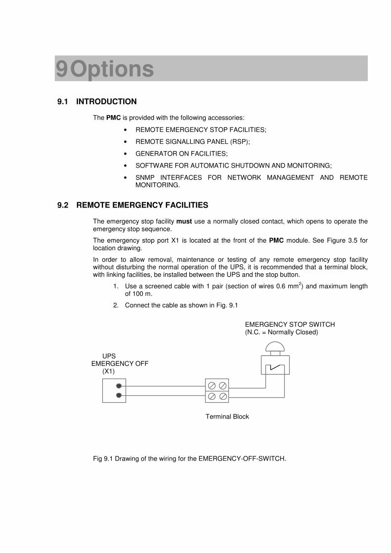
9 Options
9.1 INTRODUCTION
The PMC is provided with the following accessories:
• REMOTE EMERGENCY STOP FACILITIES;
• REMOTE SIGNALLING PANEL (RSP);
• GENERATOR ON FACILITIES;
• SOFTWARE FOR AUTOMATIC SHUTDOWN AND MONITORING;
• SNMP INTERFACES FOR NETWORK MANAGEMENT AND REMOTEMONITORING.
9.2 REMOTE EMERGENCY FACILITIES
The emergency stop facility must use a normally closed contact, which opens to operate theemergency stop sequence.
The emergency stop port X1 is located at the front of the PMC module. See Figure 3.5 forlocation drawing.
In order to allow removal, maintenance or testing of any remote emergency stop facilitywithout disturbing the normal operation of the UPS, it is recommended that a terminal block,with linking facilities, be installed between the UPS and the stop button.
1. Use a screened cable with 1 pair (section of wires 0.6 mm2) and maximum length
of 100 m.
2. Connect the cable as shown in Fig. 9.1
EMERGENCY STOP SWITCH(N.C. = Normally Closed)
UPSEMERGENCY OFF
(X1)
Terminal Block
Fig 9.1 Drawing of the wiring for the EMERGENCY-OFF-SWITCH.

A3346302IT74-GB 51
9.3 REMOTE SIGNALLING PANEL (RSP)
The optional Remote Status Panel (RSP) may be used to display UPS status information up toa distance of 100m.
No. INDICATOR INDICATOR STATUS MEANING
1 LINE GREEN
RED
Mains available
Mains not available
2 BATTERY GREEN
YELLOW
OFF
Battery OK
Battery near the end of capacity
No UPS supply or UPS on bypass
3 INVERTER GREEN
OFF
Load supplied by inverter
Inverter supply not available
4 LOAD GREEN
RED FLASHING
Load is supplied
Load is not supplied
5 ALARM RESET Push button Silence the audible alarm
6 ALARM RED
OFF
Alarm condition; check other LEDS forindication of mains and/or UPS status.
UPS is in normal operation condition
7 BYPASS RED
OFF
Load is supplied by mains
Load is supplied by inverter
Figure. 9.2: LED Indicators on Remote Signalling Panel (RSP)
Remote Signalling Panel
(6)
(5)
(1)
(1)
LINE
LINE
INV
(3)
(7)
BYPASS
(2)
BATT.
LOAD
(4)

A3346302IT74-GB 52
9.3.1 How to Connect the Remote Signalling Panel (RSP)
• Provide a 0,7.5 mm2, shielded cable (max 100 meters);
• Do not connect shielding;
• Connect a D-type, 25pin, Male connector to one end of cable;
• The other end of cable connect to the 6pin, Terminal Block inside the RSP-Boxas shown in Figure 9.3
• Connect 25 pin D-type connector to the UPS Dry Port.
Interface CableUPS End
Connects toUPSDRY PORTJD2
Connects Fig. 9.3: Connection of Remote Signalling Panel (RSP)
Details of all Dry Port connections are shown in Figure 3.10.
9.4 GENERATOR ON FACILITIES
The generator ON facility must use a normally open contact that closes to indicate that agenerator is running and supplying input power to UPS.
When used, this facility disables the UPS static bypass and prevents the UPS fromtransferring the load onto the generator power supply.
Generator alarm panel
UPSGenerator port
X2
Figure 9.4: Generator ON Connection
Remote StatusPanel (Terminal Block)
6
3
4
5
2
1
5
7
23
6
22
3
9GROUND
Mains Failure
Load on Mains/Inverter
Battery Low
+ 12 V

A3346302IT74-GB 53
9.5 POWER MODULAR CONCEPT-SOFTWARE SHUTDOWN AND MANAGEMENTSOFTWARE
9.5.1 Why is UPS Management important?
By combining a UPS with network management products, such as an SNMP protocol,System-administrators are guaranteed their data and their system will constantly be protectedfrom corruption or data loss even in the event of an extended power failure or when batteriesreach a critical low state. In the event of a power disturbance system administrators can alsomonitor their network from a central location, allowing an early detection of problems. In factutility power is unreliable at times, ensuring that all network systems have constant power canbe a difficult task. The situation becomes even more complex if systems are managed acrossa Local Area Network (LAN) or Wide Area Network (WAN) around the world.
When a power failure occurs action can be taken to protect the system and its valuable data. Ifno action is initiated by the operator, this event can seriously damage the system. The UPSsoftware will react automatically in such a case and shutdown the operating system. RITTALhas found it important to have a complete solution for its UPS and is able to offer a wide rangeof monitoring/remote controls for assuring the maximum protection degree to the RITTALcustomers.
9.5.2 Power Modular Concept-Software Shutdown and Monitoring Software
Power Modular Concept PMC-Software is an external monitoring and shutdown software whichwas designed to operate with all RITTAL UPS products, both with the DRY PORT (Relays) JD2and SMART PORT (RS232) JD1.
The software packet consists of a CD ROM for most diffused operating systems (Windows,Unix, OS/2, DEC VMS, Novell, Apple), a standard connection and a user manual.
The 25 pin port with voltage-free contacts may also be used for automatic shutdown inconnection with PMC-Software. It is necessary to provide a special cable to connect the 25pin port of the UPS and the serial port of the server.
Figure 9.5. Monitoring image.
The main characteristics of PMC-Software are:
• Automatic unattended master/slave shutdown in heterogeneous networks
• On-screen autonomy time / battery time countdown
• On-screen server log off and shutdown procedure
• Extensive logging of all UPS activity and power quality data, with timestamp
• Scheduled UPS economy mode, service mode, other systems status
• Graphical user interface for Windows compatible platforms
• Automatic unattended local shutdown

A3346302IT74-GB 54
• Special software modules to close and save open MS-Office documents.
• Compatible for all optional modules like UPSDIALER, SNMP adapters,Temperature sensors, etc.
The UPS-Management Software is a client-/server-application for networks and localworkstations. Basically PMC-Software consists of two parts: the server-module of the UPS-Management Software is UPSServ, which communicates via RS-232 cable with the UPS.Working as a background process the UPSServ collects messages, received from the UPS.The UPSServ interprets received messages and makes them available to the client-moduleUPSCli and to any SNMP-based management station.
When UPSServ detects voltage variations or a power failure it can execute various so calledsystem „event routines“, which for example may shutdown the server or send warning toconnected users. These system event routines which are a part of the UPS-ManagementSoftware can be adjusted to your demands.
The UPS management software includes with every serial number the licence for using theUPS service on one server with one UPS and an unlimited numbers of connected WINDOWSworkstations. When operating with two or more servers a licence for every additional server isrequired. It doesn’t matter if the UPS service runs at that location or if the server is halted by aUPS service via remote command. The same regulations are applicable to the use of remotesend/receive modules RCCMD and multiserver shutdown under NT, UNIX and other operatingsystems. The service programs are generally delivered as a single-licence. To use a singleCD ROM to shutdown multiple servers you have to purchase additional CD license keys.
Parallel/redundant UPS systems are also manageable by the software.
The main principle is: let introduce a shutdown of a Server only when strictly necessary. Acorrect Parallel Handling has therefore to manage a parallel system as a whole and alwaysconsidering redundancy. Following statements apply:
- Every alarm on any unit is immediately notified, but …
- … a reaction to a severe fault is introduced only when the minimum number of UPS –Modules necessary to supply the load exhibits an alarming situation.
- The real Battery autonomy time of the (whole) parallel system is computed continuously.
- Maintenance on a redundant unit may be executed without annoyance to the managementsystem (supervisor).
In order to be managed, a RITTAL UPS can be integrated into a network in two ways:
1. By means of the server which is being powered by the UPS and is integrated in thenetwork. In most of the cases the server is used as sub-agent and you only need the PMC-Software without any SNMP Adapter. You need a standard serial connection between theRS232 SMART port of the UPS and the RS232 port of the computer/server.
2. In some situations it is preferable to interface the network via an SNMP adapter. By this wayup to 50 computers can be shut down in a RCCMD environment. RCCMD (Remote ConsoleCommand) is an additional software module, which can be triggered by the SNMP device toexecutes a command (typically a shutdown command) on a remote system.

A3346302IT74-GB 55
9.6 SNMP CARD/ADAPTER FOR NETWORK MANAGEMENT /REMOTE MONITORING
The Simple Network Management Protocol (SNMP) is a worldwide-standardizedcommunication-protocol. It is used to monitor any device in the network via simple controllanguage. The UPS-Management Software also provides its data in this SNMP format with itsinternal software agent. The operating system you are using must support the SNMP protocol.We offer our software with SNMP functionality for Novell, OS/2, all Windows running onINTEL and ALPHA, DEC VMS, Apple.
Two types of SNMP interfaces with identical functionality are available: an external SNMP-Adapter (Box) and an internal SNMP-Card. Both can manage a parallel system (N modules)and return either global values - which are consistent for the whole parallel system - or specificvalues from the single modules.
Figure 9.6 SNMP Adapter
The adapter may be configured via Telnet, HTTP (Web-Browser) or serial connection(Terminal). For normal operation at least one network connection (Ethernet) is required.
The SNMP adapter can be used, utilising the RCCMD send function, for an automatic networkwide shut down or just for informing connected users. The shut down procedure can beinitiated on a low residual battery autonomy time (downtime) or by a countdown timer which isstarted at the beginning of the alarm. A shut down is therefore possible without extra inputfrom the operator, and is fully software controlled.
The small (125x70 mm) External SNMP adapter comes with following interfaces:
1. RJ-45 connector for 10/100 Base-T(autoswitchable)2. Serial Port for configuration (COM2) or optional ModBus
interface.3. Error/Link LED for UPS status4. Aux Port5. DIP Switch6. Serial Port to the UPS (COM1)7. DC Supply (9 VDC or 9-36 VDC supply, depending on model);
Figure 9.7 External SNMP Adapter
The Internal SNMP-Card can be inserted into an appropriateextension slot of the PMC. This adapter communicates via the serialport of the UPS and makes a direct multiple server shut downpossible without additional SNMP management software.
Figure 9.8 Internal SNMP Adapter
For detailed information please see Software Manual provided with the PMC-Software CDROM.RCCMD - Remote Console Command module for a multi-server shutdown. Thisstand-alone software module is designed to receive and execute a command issued by aremote device. Thanks to RCCMD it is possible to execute a shutdown in an heterogeneousmultiplatform network. The new release RCCMD2 is an application available for all OperatingSystems, analogous to PMC-Software. Our SNMP Interfaces are compatible to RCCMD.
Internal SNMP-Card
UPS
Ethernet
9
External SNMP-Adapter