Embed Size (px)
Citation preview
i
Riverbank Stability Assessment
and Applied Best Practices Guide
Pittsburgh, PA
Prepared for: City of Pittsburgh
414 Grant St.
Pittsburgh, PA 15219
Prepared by: Planning, Programs, & Project Management Division
U.S. Army Corps of Engineers, Pittsburgh District
1000 Liberty Avenue
Pittsburgh, Pennsylvania 15222
June 2021
ii
Executive Summary
Introduction There is growing consensus over the importance of considering social, political, and environmental
factors together when making decisions regarding the rehabilitation and stabilization of riverbanks
within urban settings. Toward this end, the City of Pittsburgh requested assistance from the U.S.
Army Corps of Engineers (USACE), Pittsburgh District with developing a series of tools to
facilitate effective management of approximately 43 miles of riverbank along the Allegheny,
Monongahela, and Ohio Rivers. The specific objectives of this study were to:
1. Assess and map the current condition of riverbanks within City limits
2. Develop an applied best practices document that guides future remediation of unstable
riverbanks within the context of the planning goals established by the City and its partners.
The current study was conducted under Section 22 of the Water Resources Development Act of
1974, as amended.
Riverbank Condition Assessment & Mapping The study team characterized and evaluated critical attributes controlling riverbank erosion and
failure throughout the study area, including bank material and condition, slope, the presence and
type of vegetation, extent of impervious surfaces within the riparian area, and the presence and/or
extent of existing features that can further contribute to bank instability (e.g., existing erosion
and/or undercutting). Bank material, bank condition, and slope were used to establish riverbank
segments and define 31 distinct riverbank typologies. Each riverbank segment was given an overall
condition score of either poor, fair, or favorable, depending on its underlying typology. The
presence and extent of erosion and undercutting and extent of adjacent impervious surface was
then used to further refine each riverbank segment’s overall condition and stability rating. A total
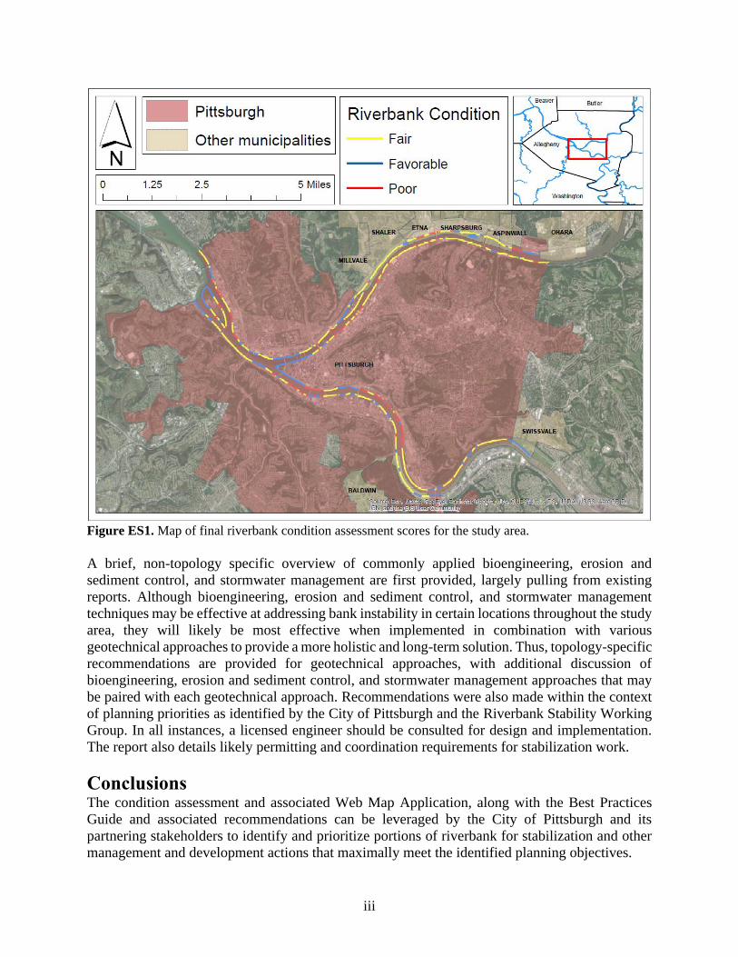
of 11.9 miles of riverbank received a ‘favorable’ condition assessment rating, 24.1 miles received
a ‘fair’ rating, and 6.7 miles received a ‘poor’ rating (Figure ES1).
Assessment data for each reach, along with photographs depicting the characteristics of each
segment were published to ArcGIS Online and an application was created to display the
characteristics. The Web Map Application can be used to visually assess riverbank conditions
throughout the study area and facilitate planning and management decisions, such as prioritizing
areas for future restoration actions. This interface is live and accessible at the following location:
https://pittsburghpa.gov/innovation-performance/interactive-maps.
Riverbank Stabilization Techniques and Applied Best Practices Results of the riverbank assessment informed a Best Practices Guide designed to assist with
identifying the most effective riverbank stabilization and rehabilitation techniques for each
riverbank typology. Riverbank stabilization approaches included in this report fall within the broad
categories of bioengineering (i.e., engineering techniques that utilize nature-based materials and
processes to encourage riverbank stabilization and ecological diversity), erosion and sediment
control, stormwater management, and geotechnical techniques.
iii
Figure ES1. Map of final riverbank condition assessment scores for the study area.
A brief, non-topology specific overview of commonly applied bioengineering, erosion and
sediment control, and stormwater management are first provided, largely pulling from existing
reports. Although bioengineering, erosion and sediment control, and stormwater management
techniques may be effective at addressing bank instability in certain locations throughout the study
area, they will likely be most effective when implemented in combination with various
geotechnical approaches to provide a more holistic and long-term solution. Thus, topology-specific
recommendations are provided for geotechnical approaches, with additional discussion of
bioengineering, erosion and sediment control, and stormwater management approaches that may
be paired with each geotechnical approach. Recommendations were also made within the context
of planning priorities as identified by the City of Pittsburgh and the Riverbank Stability Working
Group. In all instances, a licensed engineer should be consulted for design and implementation.
The report also details likely permitting and coordination requirements for stabilization work.
Conclusions The condition assessment and associated Web Map Application, along with the Best Practices
Guide and associated recommendations can be leveraged by the City of Pittsburgh and its
partnering stakeholders to identify and prioritize portions of riverbank for stabilization and other
management and development actions that maximally meet the identified planning objectives.
iv
Table of Contents
Executive Summary ...................................................................................................................... ii
Abbreviations and Acronyms ...................................................................................................... v
List of Tables ................................................................................................................................ vi
List of Figures .............................................................................................................................. vii
List of Appendices ........................................................................................................................ ix
1 Introduction ........................................................................................................................... 1
1.1 Background & Objectives ................................................................................................ 1
1.2 Coordination ..................................................................................................................... 1
1.3 Study Area ........................................................................................................................ 1
1.4 Brief History of Pittsburgh Riverbanks ............................................................................ 2
2 Riverbank Condition Assessment & Mapping ................................................................... 3
2.1 Methods ............................................................................................................................ 4
2.1.1 Criteria Development ................................................................................................ 4
2.1.2 Field Assessment ...................................................................................................... 4
2.1.3 GIS Assessment ...................................................................................................... 10
2.1.4 Condition Assignment ............................................................................................ 11
2.2 Results and Existing Conditions .................................................................................... 17
2.2.1 Field Assessment .................................................................................................... 17
2.2.2 GIS Assessment ...................................................................................................... 25
2.2.3 Condition Assignment ............................................................................................ 26
2.3 Published Map: Web Map Application .......................................................................... 28
2.3.1 Using the Web Map Application ............................................................................ 28
3 Riverbank Stabilization Techniques and Applied Best Practices ................................... 29
3.1 Bioengineering Techniques for Riverbank Stabilization ............................................... 30
3.2 Erosion and Sediment Control ....................................................................................... 35
3.2.1 Vegetation for Erosion and Sediment Control and Riverbank Stabilization .......... 38
3.3 Stormwater Management ............................................................................................... 43
3.4 Geotechnical Techniques for Riverbank Stabilization ................................................... 45
3.4.1 Stabilization Techniques for Naturalized Riverbank Typologies ........................... 45
3.4.2 Stabilization Techniques for Manmade Riverbank Typologies .............................. 56
3.5 Riverbank Stabilization and Multi-Priority Planning ..................................................... 60
4 Permitting Process and Next Steps .................................................................................... 62
4.1 Federal Permitting ............................................................................................................... 63
4.2 State of Pennsylvania Permitting ........................................................................................ 63
4.3 Allegheny County and City of Pittsburgh Permitting ......................................................... 64
5 Summary .............................................................................................................................. 65
6 Glossary of Terms ................................................................................................................ 66
7 Literature Cited ................................................................................................................... 68
v
Abbreviations and Acronyms ACCD ............................................................................. Allegheny County Conservation District
ACPW .......................................................................... Allegheny County Office of Public Works
AGC ........................................................ U.S. Army Corps of Engineers Army Geospatial Center
ALCOSAN ........................................................................... Allegheny County Sanitary Authority
BMP ...................................................................................................... Best Management Practice
CoP DCP .............................................................. City of Pittsburgh Department of City Planning
CWA ..................................................................................................................... Clean Water Act
ESRI ............................................................................. Environmental Systems Research Institute
E&S ............................................................................................................... Erosion and Sediment
GIS .............................................................................................. Geographic Information Systems
GNSS ...................................................................................... Global Navigation Satellite System
IENC ...................................................................................... Inland Electronic Navigation Charts
IPaC.............................................................................. Information for Planning and Consultation
NPDES .................................................................... National Point Discharge Elimination System
MWMO ............................................................ Mississippi Watershed Management Organization
NRCS ................................................................................ Natural Resource Conservation Service
PADCNR .................................. Pennsylvania Department of Conservation of Natural Resources
PADEP ..................................................... Pennsylvania Department of Environmental Protection
PAFBC ........................................................................... Pennsylvania Fish and Boat Commission
PHMC ............................................................. Pennsylvania Historical and Museum Commission
PAPUC ............................................................................ Pennsylvania Public Utility Commission
PASPGP-4................................................... Pennsylvania State Programmatic General Permit # 4
PennDOT ................................................................... Pennsylvania Department of Transportation
PHMC ............................................................. Pennsylvania Historical and Museum Commission
PNDI ............................................................................. Pennsylvania Natural Diversity Inventory
PNHP ............................................................................... Pennsylvania Natural Heritage Program
SHPO ......................................................................................... State Historic Preservation Office
TRM ........................................................................................................ Turf Reinforcement Mats
USACE ........................................................................................... U.S. Army Corps of Engineers
USEPA .............................................................................. U.S. Environmental Protection Agency
USFWS ............................................................................................ U.S Fish and Wildlife Service
vi
List of Tables
Table 1. Finalized list of characteristics included in the riverbank assessment. Attributes are
categorized based on assessment methods (i.e., those assessed in the field and those assessed
using existing data within GIS), as well as the type of feature each attribute represents (i.e.,
continuous or point) ...................................................................................................................4
Table 2. Definitions and key characteristics for the three natural and six manmade riverbank
types ...........................................................................................................................................5
Table 3. Definitions and key characteristics of bank condition for natural and manmade
riverbanks ...................................................................................................................................7
Table 4. Slope chart showing the relationship between the horizontal (H) and vertical (V)
components of slope as represented by ratio, percent grade, and slope angle ...........................8
Table 5. Definitions of slope assessment criteria for natural and manmade riverbanks .................9
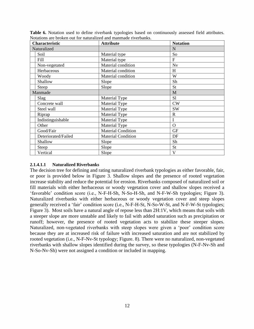
Table 6. Notation used to define riverbank typologies based on continuously assessed field
attributes. Notations are broken out for natural and manmade riverbanks .............................. 12
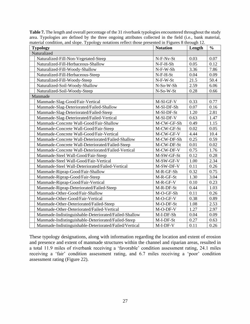
Table 7. The length and overall percentage of the 31 riverbank typologies encountered
throughout the study area. Typologies are defined by the three ongoing attributes collected in
the field (i.e., bank material, material condition, and slope. Typology notations reflect those
presented in Figures 8 through 12 ............................................................................................27
Table 8. Summary of bioengineering riverbank stabilization techniques .....................................31
Table 9. Selected Erosion and Sediment Control Best Management Practices suitable for
riverbank stabilization techniques............................................................................................36
Table 10. Invasive species prolific along riverbanks in Pittsburgh, PA .......................................39
Table 11. General Practices of Invasive Plant Management .........................................................39
Table 12. Selected recommended seed mixes based on site condition, modified from PADEP
Erosion and Sediment Control Manual ....................................................................................40
Table 13. Recommendations based on river zone .........................................................................40
Table 14. Recommended species based on riverbank flooding frequency and elevation for
Pittsburgh region ......................................................................................................................41
Table 15. Stormwater Management Techniques ..........................................................................43
Table 16. Typologies applicable for flattening the slope ..............................................................46
Table 17. Typologies applicable for terracing the slope ...............................................................47
Table 18. Typologies applicable for excavation and replacement ................................................49
Table 19. Typologies applicable for buttressing a slope ...............................................................52
Table 20. Typologies applicable for installing a retaining wall ....................................................54
Table 21. Manmade typologies applicable for flattening a slope .................................................57
Table 22. Manmade typologies applicable for terracing a slope ...................................................57
Table 23. Manmade typologies applicable for excavating and replacing .....................................57
Table 24. Manmade typologies applicable for installing a retaining wall ....................................58
Table 25. Manmade typologies applicable when repairing an existing structure .........................59
Table 26. Manmade typologies applicable when replacing an existing structure .........................59
Table 27. Example recommendations for stabilization actions that would help meet each of the
four planning priorities ............................................................................................................60
Table 28. List of possible agency coordination.............................................................................64
vii
List of Figures
Figure 1. Extent of assessed riverbanks within the City of Pittsburgh and adjacent
municipalities. Location of the study area within Allegheny County is also shown .................2
Figure 2. Photographs showing a variety of riverbank land uses and a barge carrying coal ..........3
Figure 3. Photographs showing a naturalized riverbank and manmade concrete wall ...................6
Figure 4. Photographs showing a deteriorating manmade slag and naturalized vegetated slope ...8
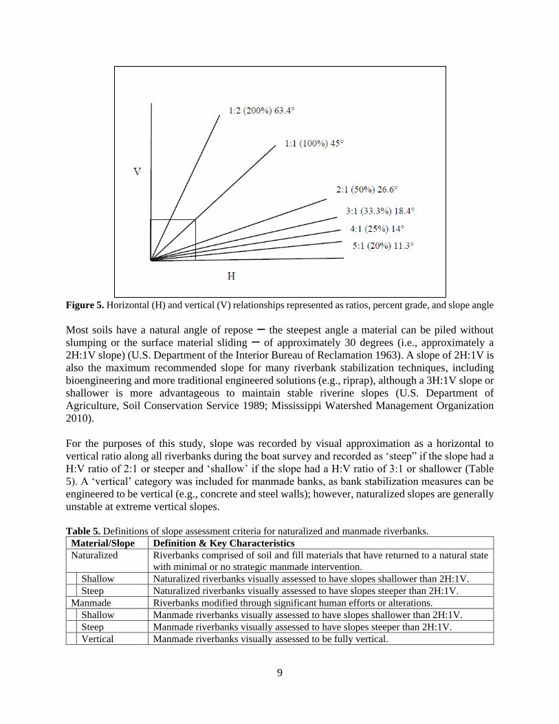
Figure 5. Horizontal (H) and vertical (V) relationships represented as ratios, percent grade, and
slope angle .................................................................................................................................9
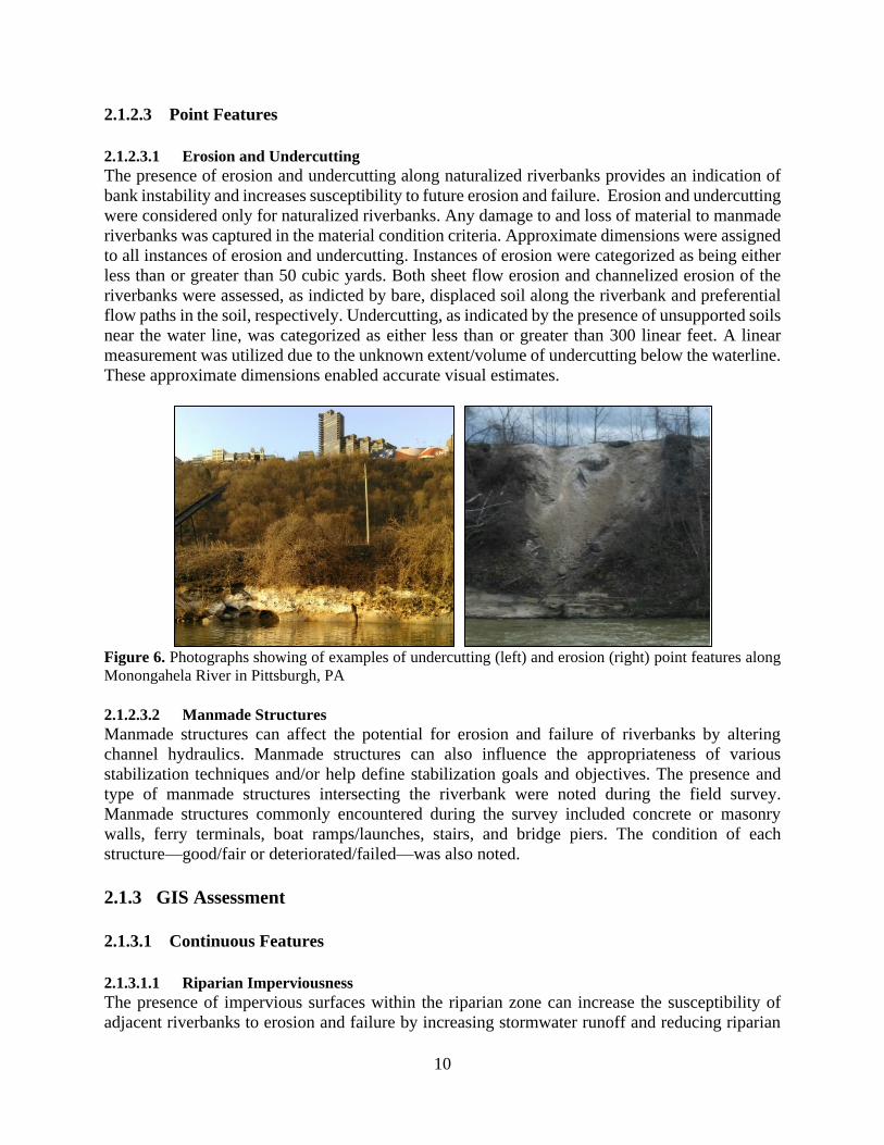
Figure 6. Photographs showing of examples of undercutting and erosion point features ............10
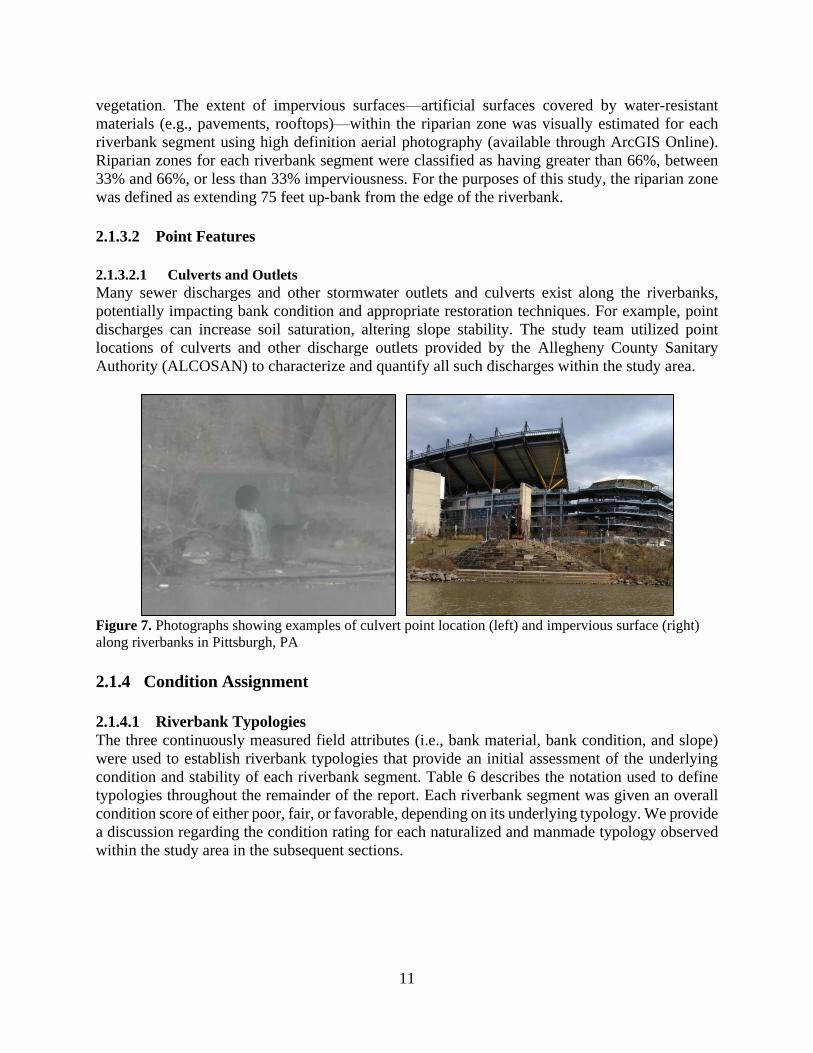
Figure 7. Photographs showing examples of culvert point location and impervious surface .......11
Figure 8. Decision tree used to define and assign bank condition scores to natural riverbank
typologies. Missing typologies and associated condition scores indicate typologies that were
not encountered within the study area .....................................................................................13
Figure 9. Decision tree used to define and assign bank condition scores to manmade slag
riverbank typologies. Missing typologies and associated condition scores indicate typologies
that were not encountered within the study area ......................................................................14
Figure 10. Decision tree used to define and assign bank condition scores to manmade slag
riverbank typologies. Missing typologies and associated condition scores indicate typologies
that were not encountered within the study area ......................................................................15
Figure 11. Decision tree used to define and assign bank condition scores to manmade riprap
typologies. Missing typologies and associated condition scores indicate typologies that were
not encountered within the study area .....................................................................................16
Figure 12. Decision tree used to define and assign bank condition scores to manmade
indistinguishable and manmade other typologies. Missing typologies and associated
condition scores indicate typologies that were not encountered within the study area ...........17
Figure 13. Map showing the location and extent of natural and manmade riverbanks throughout
the study area. Locations and extents of specific natural (soil and fill) and manmade
(indistinguishable, other, riprap, slag, concrete walls, and steel walls) can be found in the
online web application .............................................................................................................18
Figure 14. Length of riverbank within the study area that classifies as natural and manmade
materials ...................................................................................................................................19
Figure 15. Map showing the location and extent of natural and manmade riverbank conditions
throughout the study area .........................................................................................................20
Figure 16. Length of natural and manmade riverbanks within the study area that categorized by
condition ..................................................................................................................................21
Figure 17. Map showing the location and extent of riverbanks with shallow, steep, and vertical
slopes throughout the study area ..............................................................................................22
Figure 18. Length of natural and manmade riverbanks within the study characterized by shallow
(i.e., less than 2H:1V), steep (i.e., greater than 2H:1V), and vertical slopes ...........................23
Figure 19. Location of distinct areas of erosion and undercutting throughout the study area ......24
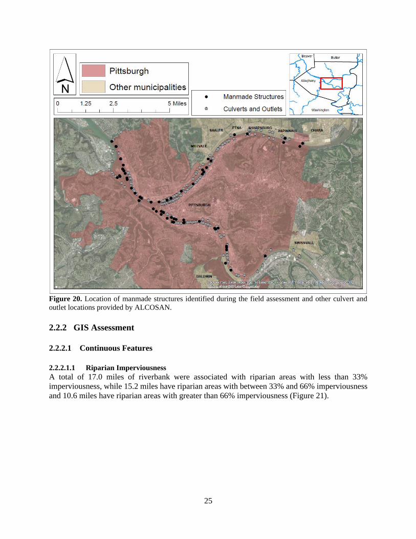
Figure 20. Location of manmade structures identified during the field assessment and other
culvert and outlet locations provided by ALCOSAN ..............................................................25
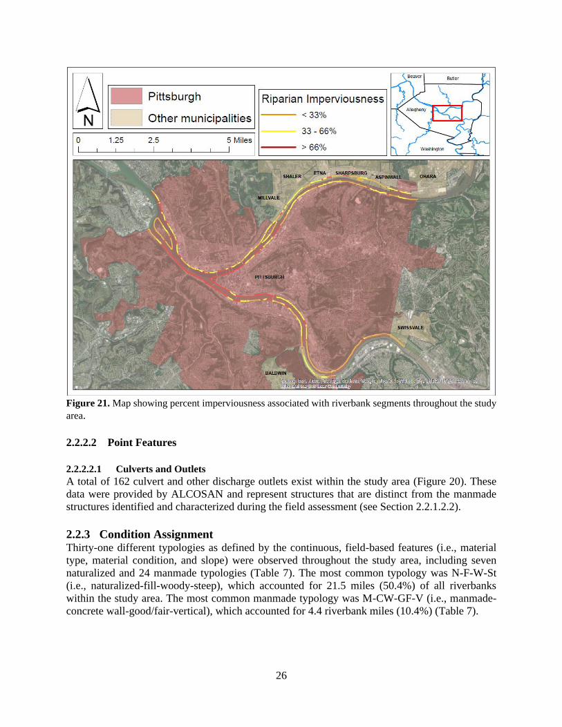
Figure 21. Map showing the location and extent of riverbanks with shallow, steep, and vertical
slopes throughout the study area ..............................................................................................26
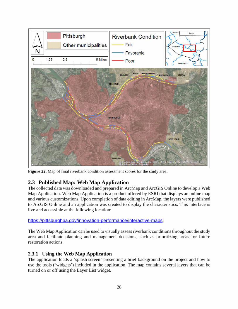
Figure 22. Map of final riverbank condition assessment scores for the study area ......................28
viii
Figure 23. Three riverbank zones described in riverbank stabilization techniques ......................30
Figure 24. Diagram and photo of installed brush mattress ...........................................................32
Figure 25. Diagram and photo of bush layering ...........................................................................32
Figure 26. Diagram and photo of a turf reinforcement mat ..........................................................32
Figure 27. Diagram and photo of live staking in combination with tree revetments and erosion
control blanket .........................................................................................................................33
Figure 28. Photos of root wad stabilization and natural boulder stabilization ..............................33
Figure 29. Diagram and photo of vegetated geogrid ....................................................................33
Figure 30. Diagram and photo of live fascines, bio-logs, and seeded erosion control blanket ....34
Figure 31. Diagram and photo of installed bio-log .......................................................................34
Figure 32. Diagram and photo of installed vegetated erosion control blanket .............................34
Figure 33. Five main sources of water-generated erosion acting on riverbanks ..........................35
Figure 34. Cross-sectional and plan views of filter sock application ...........................................36
Figure 35. Cross-sectional and plan views of filter berm application ..........................................37
Figure 36. Diagram and photo of vegetative filter strip application .............................................37
Figure 37. Diagram and photos of silt fence and super silt fence application ..............................37
Figure 38. Diagrams of stair step grading and grooved slope surface roughening techniques .....37
Figure 39. Diagram and photo of erosion control blanket application .........................................38
Figure 40. Diagram and photo of cellular confinement system application .................................38
Figure 41. Diagram and photo of green roof application ..............................................................44
Figure 42. Diagram of an open canal and sedimentation basin ....................................................44
Figure 43. Diagram of a bioretention swale and vegetated swale ................................................44
Figure 44. Diagram of an underground substrate filter and water storage cistern ........................44
Figure 45. Typical cross section view and photograph showing the flattening of an existing
unstable slope with erosion control fabric placed on the flattened slope ................................46
Figure 46. Profile view of flattened slop with bioengineering stabilization techniques ...............47
Figure 47. Typical cross section view and photograph of a terraced slope installed to increase
stability and provide access along walking path ......................................................................48
Figure 48. Example of a terraced slope design with integration of bioengineering techniques for
section of riverbank along the Ohio River in Pittsburgh, PA ..................................................48
Figure 49. Typical cross section of excavation and replacement of an existing unstable slope ...49
Figure 50. Riprap rock armoring with integration of vegetation and geotextile fabric ................50
Figure 51. Profile and plan view diagrams of rock barb installation as a rock
armoring/excavation and replacement technique .....................................................................51
Figure 52. Typical cross section of a buttress constructed to stabilize a slope .............................52
Figure 53. Typical cross section view showing a constructed wall to stabilize a slope and photos
of constructed retaining walls along the riverfronts of Pittsburgh ...........................................53
Figure 54. Retaining wall system including riprap armoring at base, geotextile installation
behind the wall and vegetated erosion control blanket installation on the top of the wall ......54
Figure 55. Diagram of crib wall retaining structure with vegetation integrated into design ........55
Figure 56. Gabion wall installation that utilize bioengineering techniques ..................................56

ix
List of Appendices
Appendix A: NRCS Soil Survey of Riparian Corridor within Project Area
1
1 Introduction
1.1 Background & Objectives Bank erosion and failure represent natural processes that are integral to the functioning of river
ecosystems (Florsheim et al. 2008). However, land use change within the watershed (e.g.,
increased urbanization and floodplain development) and modifications to the natural channel (e.g.,
loss of natural vegetation and construction of engineered riverbanks) and flow regime (e.g.,
upstream reservoirs and locks and dams) can alter the natural rate of riverbank erosion/failure and
result in socioeconomic and ecological consequences (Geyer et al. 2000, Allan 2004, Maynord et
al. 2008, Duro et al. 2020). This is particularly true for urban population centers, which are often
characterized by extensive development around and significant modification to river channels in
order to take advantage of the vital services they provide, including water provision, wastewater
assimilation, recreation, navigation, and transport (Grimm et al. 2008).
There is growing consensus over the importance of considering social, political, and environmental
factors together when making decisions regarding the rehabilitation and stabilization of riverbanks
within urban settings (Findlay and Taylor 2006; Gurnell et al. 2007). Sustainability of the coupled
socioeconomic and ecological system requires placing the river at the center of urban planning
such that decisions are made to maximize effective use of the river while recognizing that a
healthy, functioning river is vital to maintaining its utility. There have been recent calls for the
development of tools capable of facilitating the identification, prioritization, and implementation
of sustainable development activities and rehabilitation of riverbanks and their associated riparian
corridors in urban areas (Johnson et al. 2007; Everard and Moggridge 2012).
Toward this end, the City of Pittsburgh requested assistance from the U.S. Army Corps of
Engineers (USACE), Pittsburgh District (District) with developing a series of tools to facilitate
effective management of riverbanks and associated riparian areas along the Allegheny,
Monongahela, and Ohio Rivers. The specific objectives of this study were to:
1. Assess and map the current condition of riverbanks within City limits, and
2. Develop an applied best practices document that guides future remediation of unstable
riverbanks within the context of the planning goals established by the City and its partners.
1.2 Coordination The current study was conducted under Section 22 of the Water Resources Development Act of
1974, as amended, which provides authority for USACE to provide planning assistance and
technical expertise to support states, local governments, and other non-Federal entities in broad,
comprehensive water resource planning efforts. All work described in subsequent sections was
cost shared on a 50% federal and 50% non-federal basis per Section 22 requirements.
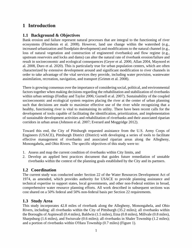
1.3 Study Area This study incorporates 42.8 miles of riverbank along the Allegheny, Monongahela, and Ohio
Rivers, including: all riverbanks within the City of Pittsburgh (35.2 miles); all riverbanks within
the Boroughs of Aspinwall (0.4 miles), Baldwin (1.5 miles), Etna (0.8 miles), Millvale (0.8 miles),
Sharpsburg (1.6 miles), and Swissvale (0.6 miles); all riverbanks in Shaler Township (1.2 miles);
and a portion of riverbanks within O'Hara Township (0.7 miles) (Figure 1).
2
Figure 1. Extent of assessed riverbanks along the Allegheny, Monongahela, and Ohio rivers within the City
of Pittsburgh and adjacent municipalities. Location of the study area within Allegheny County is also
shown. The location of Herrs Island on Allegheny River is also shown with black and red radial.
1.4 Brief History of Pittsburgh Riverbanks As can be seen in the Figure 1, the metropolitan area of Pittsburgh is centered around the
confluence of the Allegheny and Monongahela rivers where they form the Ohio river. A 24-mile
long pool, referred to as the Emsworth Pool or Pittsburgh Pool, spans the sections of the three
rivers within the city limits with a targeted pool elevation of 710-feet maintained by the USACE
Emsworth Locks and Dams (incudes Emsworth Gated Dam at River Mile 6.2 and a backchannel
dam at Neville Island at River Mile 6.8) (USACE 2021). The Pittsburgh District operates 23 locks
and dams on the Allegheny, Monongahela, and Ohio Rivers. The main purpose of the locks and
dams is to improve and maintain the navigability of the rivers. Navigation and engineering of the
three rivers surrounding Pittsburgh has served a prominent role in the industrial and economic
history of the city and region. Engineering modifications including removing large rocks and
snags, constructing low dams to deepen channels, and widening river extents to improve
navigation on the three rivers surrounding Pittsburgh can be traced as far back as the late 1700’s.
By 1824, USACE assumed authority over the development of the rivers which resulted in the
eventual large scale engineering improvements and canalization efforts that transformed
3
navigation for the region and set the city of Pittsburgh up to serve as a commercial and industrial
hub throughout the industrial revolution (Moxley, 2001). The Pittsburgh steel industry as well as
coal and gravel mining, natural gas production, timbering, manufacturing, and the expansive
railway system relied heavily on the rivers and riverbanks. Industrialization during the 1800’s and
1900’s brought substantial modification to the riverbanks of Pittsburgh including, but not limited
to, deforestation, vast removal of natural soils, pollution to the soil and water, and widespread
modification and installation of manmade materials along the riverbanks (Andropogon, 2006).
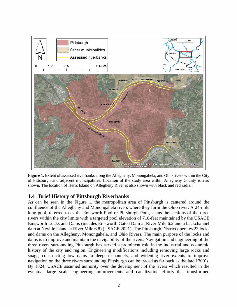
Figure 2. Photographs showing a variety of riverbank land use (left) and a barge carrying coal (right) along
the Monongahela River in Pittsburgh, PA
2 Riverbank Condition Assessment & Mapping
From a geomorphic perspective, a riverbank is defined as the landform distinguished by the
topographic gradient extending from the bed of the river channel along the lateral land-water
margin toward the edge of the floodplain (Florsheim et al. 2008). The riverbank assessment in this
study only considers the portion of the riverbank above the water surface and within the 75-foot
riparian buffer at the time the survey was conducted. River elevations at Point State Park ranged
from 710.5 feet to 710.7 feet during the time of sampling.
Riverbank erosion and failure is controlled by multiple interacting factors, including bank material
and condition, river morphology (i.e., shape of the river channel), and vegetation and land use
within the riparian zone. The riparian zone is defined as the land area that serves as the interface
between the terrestrial and river ecosystems bordering the river channel, including the riverbank
and floodplain (Geyer et al. 2000; Wynn and Mostaghimi 2006). The study team developed a series
of criteria to assess how each of these critical factors influences the stability of riverbanks
throughout the study area and synthesized these criteria into a continuous measure of riverbank
condition. This section describes the methods used to develop and assess these criteria and results
of the riverbank condition assessment.
4
2.1 Methods
2.1.1 Criteria Development The project team developed a preliminary list of criteria to characterize and quantify critical aspects controlling riverbank erosion and failure, including bank material (e.g., native and naturalized soils vs. various manmade materials) (Hook 1980; Florsheim et al. 2008), the presence and type of vegetation (Geyer et al. 2000, Polvi et al. 2004), and extent of impervious surfaces within the riparian area (Allan 2004), as well as the presence and/or extent of existing features that can further contribute to bank instability, including existing erosion and/or undercutting and manmade structures (e.g., culverts/outfalls).
A preliminary site visit was conducted to optimize the data collection process and redefine
characteristics to accurately classify physical attributes. Herrs Island was selected for the initial
reconnaissance effort due to ease of access and the varying terrain along the riverbank (Figure 1).
This initial effort led to the determination that several attributes were most effectively and
efficiently assessed using existing geospatial data within GIS rather than in the field. It was also
determined that several attributes needed to be collected continuously, whereas others were best
represented as point characteristics. Point characteristics were defined as any attributes that
represented discrete features with lengths of approximately 100 yards or less. The final list of
attributes, including the methods for assessing and representing them in GIS, is presented in Table
1. Final criteria are described in detail in the following sections.
Table 1. Finalized list of characteristics included in the riverbank assessment. Attributes are categorized
based on assessment methods (i.e., those assessed in the field and those assessed using existing data within
GIS), as well as the type of feature each attribute represents (i.e., continuous or point).
Attribute Assessment methods Feature type
Bank material Field Continuous
Material condition Field Continuous
Bank slope Field Continuous
Erosion Field Point
Undercutting Field Point
Structure Field Point
Riparian impervious GIS Continuous
Culvert/outlet GIS Point
2.1.2 Field Assessment
2.1.2.1 Data Collection
A geodatabase containing all assessment criteria was created using geographic information
systems (GIS) [ArcMap, version 10.6.1; Environmental Systems Research Institute (ESRI),
Redlands, California] and implemented with the ESRI Collector Application installed on a Trimble
TDC-100 Global Navigation Satellite System (GNSS) data collector. The Trimble TDS-100 GNSS
data collector leverages global positioning systems and other navigation satellite constellations
and enabled the study team to geo-reference all riverbank attributes and associated photos.
5
Field data were collected via boat traveling along the length of each riverbank for the entirety of
the study area. The assessment was completed in three days with an average of 12.7 miles mapped
per day. Data collection occurred in early spring (March 2, 3, and 10, 2020) during the dormant
growing season to ensure vegetation foliage would not inhibit line of sight to the riverbank.
Continuous attributes (i.e., bank slope, material, and condition) were used to determine the overall
typology of the riverbank at any given location. The study team traveled parallel to the riverbank
until a change in one of the continuous attributes resulted in a change in the overall bank typology.
The location of a change in typology was georeferenced using the Trimble TDS-100 GNSS data
collector and a new riverbank segment was classified in the data collector geodatabase. Within
each riverbank segment, point features were georeferenced and characteristics and photos of those
features were collected. Distinct riverbank typologies and segments and associated point feature
characteristics of those banks were identified and assessed for all riverbanks within the study area.
Detailed descriptions of each attribute collected during the field assessment are provided below.
2.1.2.2 Continuous Features
2.1.2.2.1 Bank Material & Type
Riverbank material was characterized as either naturalized/native or manmade. As referenced
above in Section 1.4, the industrial and engineering modifications to the riverbanks within the city
of Pittsburgh and the study area resulted in replacement of most of the native soil with urban fill.
The term naturalized is used in the context of this report to describe the sections of the riverbank
containing soil (including modified native soils) and fill materials that have returned to a natural
state with minimal or no strategic manmade intervention with varying degrees of sucess. The study
assumes all the riverbanks in the study area have experienced some degree of anthropomorphic
modification. A soil resource report from the US Department of Agriculture (USDA) Natural
Resources Conservation Service (NRCS) Web Soil Survey was created for the study area including
the 75-foot riparian buffer (NRCS 2019) and can be found in Appendix A: NRCS Soil Survey of
Riparian Corridor within Project Area. Urban land is the dominant soil type that was characterized
in the soil report, with lesser amounts of native soil present. Urban land may be fill, rubble, or
human transported material. Urban land, as classified by the NRCS soil report, makes up most of
the areas characterized in the assessment as naturalized riverbank and may or may not be vegetated.
Naturalized riverbanks were divided into two separate types based on bank material, including
those comprised of naturalized or native soils (i.e., ‘soil’) which were generally more stabilized
and vegetated and those comprised of visibly altered material and rubble (i.e. ‘fill’) which may or
may not be vegetated. Manmade riverbanks were defined as those modified through significant
human efforts or alterations and were divided into six different material types: riprap, slag,
concrete wall, steel wall, indistinguishable, and other. Each material type is defined below in Table
2, including key observations that differentiate them from one another.
Table 2. Definitions and key characteristics for the three naturalized and six manmade riverbank types.
Material/Type Definition & Key Characteristics Naturalized Riverbanks comprised of soil and fill materials that have returned to a natural state
with minimal or no strategic manmade intervention
Naturalized and
Native Soil
Riverbanks where the underlying materials are native soils or naturalized soil if
placed by humans. These soils are likely weathered and loosely compacted and
may or may not be vegetated. If no nearby modifications were noted, it was
6
Material/Type Definition & Key Characteristics assumed that the soils have not been substantially altered in recent history by
human activities.
Fill Riverbanks where the underlying materials were assumed to be placed or
compacted with manmade intervention. It was assumed that the presence of
manmade infrastructure in the riparian area required site development prior to
construction and/or destruction, including the use of fill material to augment the
riverbank. Materials directly adjacent or underlying existing or relic development
and infrastructure was assumed to be fill.
Manmade Riverbanks modified through significant human efforts or alterations.
Riprap Manmade riverbanks composed of strategically placed natural or man-made stone,
including boulders, cobbles, gravels and/or gabion baskets.
Slag Manmade riverbanks with discarded slag ─ a stony byproduct separated from
metals during the smelting or refining of ore ─ coating the underlying
soil/substrates. This material type was commonly found adjacent to existing or
pre-existing industrial plants.
Concrete wall Manmade riverbanks composed of various concrete structures.
Steel wall Manmade riverbanks composed of steel structures (e.g., sheet pile walls).
Other Manmade riverbanks comprised of materials with few occurrences throughout the
study area (e.g., timber, brick). Material type was recorded during the field survey.
Indistinguishable Manmade riverbanks for which material composition was not readily discernable.
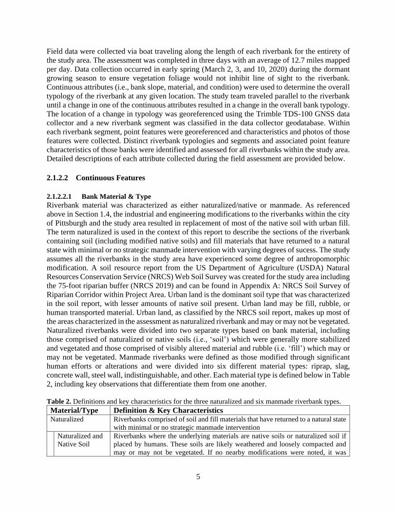
Throughout the study area, there were occasions when the riverbank consisted of a combination
of materials. In these instances, the riverbank was classified relative to the material with the lowest
elevation, as this was the material the river is most frequently in contact with. Given the size of
the study area and timing of data collection during the dormant growing season (i.e., leaf-off
period), it was not feasible to obtain more detailed information on the composition of bank material
or the associated vegetation type and structure.
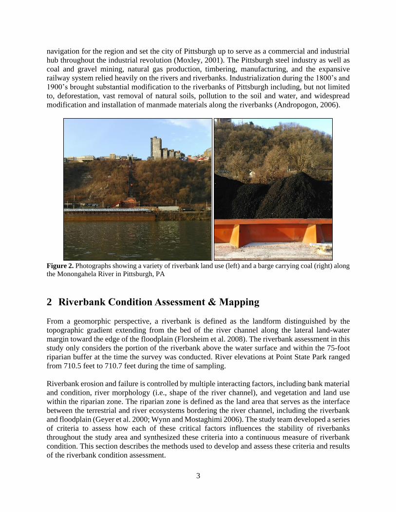
Figure 3. Photographs showing a naturalized riverbank (left) and manmade concrete wall (right) along the
Monongahela River in Pittsburgh, PA.
7
2.1.2.2.2 Material Condition
Riverbank material condition was determined during the boat survey by observing the presence of
vegetation, presence of manmade materials, and presence and extent of erosion. The naturalized
riverbank condition was assessed with respect to the presence and general type of vegetation.
Previous research has shown the presence and type of vegetation to be a critical factor in
controlling riverbank erosion and failure (Geyer et al. 2000, Polvi et al. 2004). Naturalized
riverbanks were assigned to one of three conditions based on presence and type of ground cover
vegetation, including herbaceous (non-woody stems, include grasses and ferns), non-vegetated,
and woody (trees, shrubs, lianas). A detailed survey of plant species was outside of the scope of
this study and was not feasible given the method of data collection (boat survey) and time of year
(leaf-off period). The survey did not include an inventory of tree species or mapping of tree canopy.
Geospatial data of the existing tree canopy for the city of Pittsburgh from Tree Pittsburgh (2015)
was reviewed (https://gis.pittsburghpa.gov/pghenvironmental/).
Manmade riverbanks had two different material conditions—good/fair and deteriorated/failed—
that were assigned based on presence and extent of damage and apparent instability. Each material
condition is defined below in Table 3.
Table 3. Definitions and key characteristics of bank condition for naturalized and manmade riverbanks.
Material/Condition Definition & Key Characteristics
Naturalized Riverbanks comprised of soil and fill materials that have returned to a natural
state with minimal or no strategic manmade intervention.
Non-Vegetated Naturalized riverbanks characterized primarily by exposed soils/substrates and
a general lack of vegetation.
Woody Naturalized riverbanks dominated by perennial trees and shrubs having stiff
stems and bark.
Herbaceous Naturalized riverbanks dominated by plants that have no persistent woody stems
above ground (e.g., grasses).
Manmade Riverbanks modified through significant human efforts or alterations.
Good / Fair Manmade riverbanks that appear to be in-tact and stable and with minimal
weathering and damage.
Deteriorated /
Failed
Manmade riverbanks that appear to be unstable (e.g., the presence of bare soil/fill
that signifies erosion or failure of the bank) and/or extensively damaged (e.g.,
missing material).
8
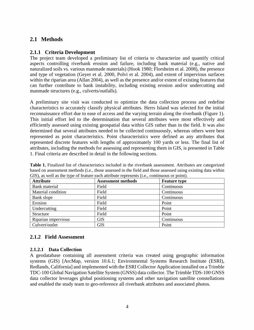
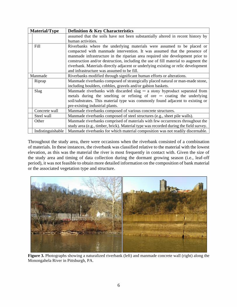
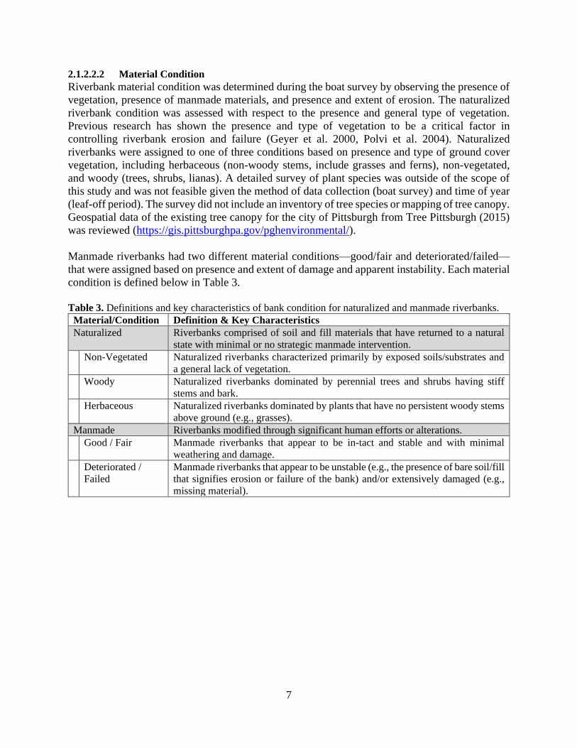
Figure 4. Photographs showing a deteriorating manmade slag (left) and naturalized vegetated slope (right)
along Allegheny River in Pittsburgh, PA.
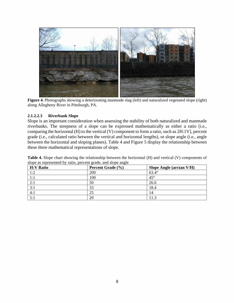
2.1.2.2.3 Riverbank Slope
Slope is an important consideration when assessing the stability of both naturalized and manmade
riverbanks. The steepness of a slope can be expressed mathematically as either a ratio [i.e.,
comparing the horizontal (H) to the vertical (V) component to form a ratio, such as 2H:1V], percent
grade (i.e., calculated ratio between the vertical and horizontal lengths), or slope angle (i.e., angle
between the horizontal and sloping planes). Table 4 and Figure 5 display the relationship between
these three mathematical representations of slope.
Table 4. Slope chart showing the relationship between the horizontal (H) and vertical (V) components of
slope as represented by ratio, percent grade, and slope angle
H:V Ratio Percent Grade (%) Slope Angle (arctan V/H)
1:2 200 63.4°
1:1 100 45°
2:1 50 26.6
3:1 33 18.4
4:1 25 14
5:1 20 11.3
9
Figure 5. Horizontal (H) and vertical (V) relationships represented as ratios, percent grade, and slope angle
Most soils have a natural angle of repose ꟷ the steepest angle a material can be piled without
slumping or the surface material sliding ꟷ of approximately 30 degrees (i.e., approximately a
2H:1V slope) (U.S. Department of the Interior Bureau of Reclamation 1963). A slope of 2H:1V is
also the maximum recommended slope for many riverbank stabilization techniques, including
bioengineering and more traditional engineered solutions (e.g., riprap), although a 3H:1V slope or
shallower is more advantageous to maintain stable riverine slopes (U.S. Department of
Agriculture, Soil Conservation Service 1989; Mississippi Watershed Management Organization
2010).
For the purposes of this study, slope was recorded by visual approximation as a horizontal to
vertical ratio along all riverbanks during the boat survey and recorded as ‘steep” if the slope had a
H:V ratio of 2:1 or steeper and ‘shallow’ if the slope had a H:V ratio of 3:1 or shallower (Table
5). A ‘vertical’ category was included for manmade banks, as bank stabilization measures can be
engineered to be vertical (e.g., concrete and steel walls); however, naturalized slopes are generally
unstable at extreme vertical slopes.
Table 5. Definitions of slope assessment criteria for naturalized and manmade riverbanks.
Material/Slope Definition & Key Characteristics
Naturalized Riverbanks comprised of soil and fill materials that have returned to a natural state
with minimal or no strategic manmade intervention.
Shallow Naturalized riverbanks visually assessed to have slopes shallower than 2H:1V.
Steep Naturalized riverbanks visually assessed to have slopes steeper than 2H:1V.
Manmade Riverbanks modified through significant human efforts or alterations.
Shallow Manmade riverbanks visually assessed to have slopes shallower than 2H:1V.
Steep Manmade riverbanks visually assessed to have slopes steeper than 2H:1V.
Vertical Manmade riverbanks visually assessed to be fully vertical.
10
2.1.2.3 Point Features
2.1.2.3.1 Erosion and Undercutting
The presence of erosion and undercutting along naturalized riverbanks provides an indication of
bank instability and increases susceptibility to future erosion and failure. Erosion and undercutting
were considered only for naturalized riverbanks. Any damage to and loss of material to manmade
riverbanks was captured in the material condition criteria. Approximate dimensions were assigned
to all instances of erosion and undercutting. Instances of erosion were categorized as being either
less than or greater than 50 cubic yards. Both sheet flow erosion and channelized erosion of the
riverbanks were assessed, as indicted by bare, displaced soil along the riverbank and preferential
flow paths in the soil, respectively. Undercutting, as indicated by the presence of unsupported soils
near the water line, was categorized as either less than or greater than 300 linear feet. A linear
measurement was utilized due to the unknown extent/volume of undercutting below the waterline.
These approximate dimensions enabled accurate visual estimates.
Figure 6. Photographs showing of examples of undercutting (left) and erosion (right) point features along
Monongahela River in Pittsburgh, PA
2.1.2.3.2 Manmade Structures
Manmade structures can affect the potential for erosion and failure of riverbanks by altering
channel hydraulics. Manmade structures can also influence the appropriateness of various
stabilization techniques and/or help define stabilization goals and objectives. The presence and
type of manmade structures intersecting the riverbank were noted during the field survey.
Manmade structures commonly encountered during the survey included concrete or masonry
walls, ferry terminals, boat ramps/launches, stairs, and bridge piers. The condition of each
structure—good/fair or deteriorated/failed—was also noted.
2.1.3 GIS Assessment
2.1.3.1 Continuous Features
2.1.3.1.1 Riparian Imperviousness
The presence of impervious surfaces within the riparian zone can increase the susceptibility of
adjacent riverbanks to erosion and failure by increasing stormwater runoff and reducing riparian
11
vegetation. The extent of impervious surfaces—artificial surfaces covered by water-resistant
materials (e.g., pavements, rooftops)—within the riparian zone was visually estimated for each
riverbank segment using high definition aerial photography (available through ArcGIS Online).
Riparian zones for each riverbank segment were classified as having greater than 66%, between
33% and 66%, or less than 33% imperviousness. For the purposes of this study, the riparian zone
was defined as extending 75 feet up-bank from the edge of the riverbank.
2.1.3.2 Point Features
2.1.3.2.1 Culverts and Outlets
Many sewer discharges and other stormwater outlets and culverts exist along the riverbanks,
potentially impacting bank condition and appropriate restoration techniques. For example, point
discharges can increase soil saturation, altering slope stability. The study team utilized point
locations of culverts and other discharge outlets provided by the Allegheny County Sanitary
Authority (ALCOSAN) to characterize and quantify all such discharges within the study area.
Figure 7. Photographs showing examples of culvert point location (left) and impervious surface (right)
along riverbanks in Pittsburgh, PA
2.1.4 Condition Assignment
2.1.4.1 Riverbank Typologies
The three continuously measured field attributes (i.e., bank material, bank condition, and slope)
were used to establish riverbank typologies that provide an initial assessment of the underlying
condition and stability of each riverbank segment. Table 6 describes the notation used to define
typologies throughout the remainder of the report. Each riverbank segment was given an overall
condition score of either poor, fair, or favorable, depending on its underlying typology. We provide
a discussion regarding the condition rating for each naturalized and manmade typology observed
within the study area in the subsequent sections.
12
Table 6. Notation used to define riverbank typologies based on continuously assessed field attributes.
Notations are broken out for naturalized and manmade riverbanks.
Characteristic Attribute Notation
Naturalized N
Soil Material type So
Fill Material type F
Non-vegetated Material condition Nv
Herbaceous Material condition H
Woody Material condition W
Shallow Slope Sh
Steep Slope St
Manmade M
Slag Material Type Sl
Concrete wall Material Type CW
Steel wall Material Type SW
Riprap Material Type R
Indistinguishable Material Type I
Other Material Type O
Good/Fair Material Condition GF
Deteriorated/Failed Material Condition DF
Shallow Slope Sh
Steep Slope St
Vertical Slope V
2.1.4.1.1 Naturalized Riverbanks
The decision tree for defining and rating naturalized riverbank typologies as either favorable, fair,
or poor is provided below in Figure 3. Shallow slopes and the presence of rooted vegetation
increase stability and reduce the potential for erosion. Riverbanks composed of naturalized soil or
fill materials with either herbaceous or woody vegetation cover and shallow slopes received a
‘favorable’ condition score (i.e., N-F-H-Sh, N-So-H-Sh, and N-F-W-Sh typologies; Figure 3).
Naturalized riverbanks with either herbaceous or woody vegetation cover and steep slopes
generally received a ‘fair’ condition score (i.e., N-F-H-St, N-So-W-St, and N-F-W-St typologies;
Figure 3). Most soils have a natural angle of repose less than 2H:1V, which means that soils with
a steeper slope are more unstable and likely to fail with added saturation such as precipitation or
runoff; however, the presence of rooted vegetation acts to stabilize these steeper slopes.
Naturalized, non-vegetated riverbanks with steep slopes were given a ‘poor’ condition score
because they are at increased risk of failure with increased saturation and are not stabilized by
rooted vegetation (i.e., N-F-Nv-St typology; Figure. 8). There were no naturalized, non-vegetated
riverbanks with shallow slopes identified during the survey, so these typologies (N-F-Nv-Sh and
N-So-Nv-Sh) were not assigned a condition or included in mapping.
13
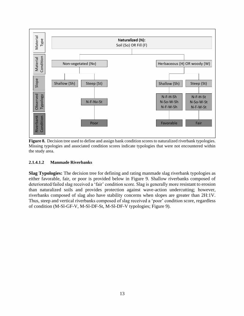
Figure 8. Decision tree used to define and assign bank condition scores to naturalized riverbank typologies.
Missing typologies and associated condition scores indicate typologies that were not encountered within
the study area.
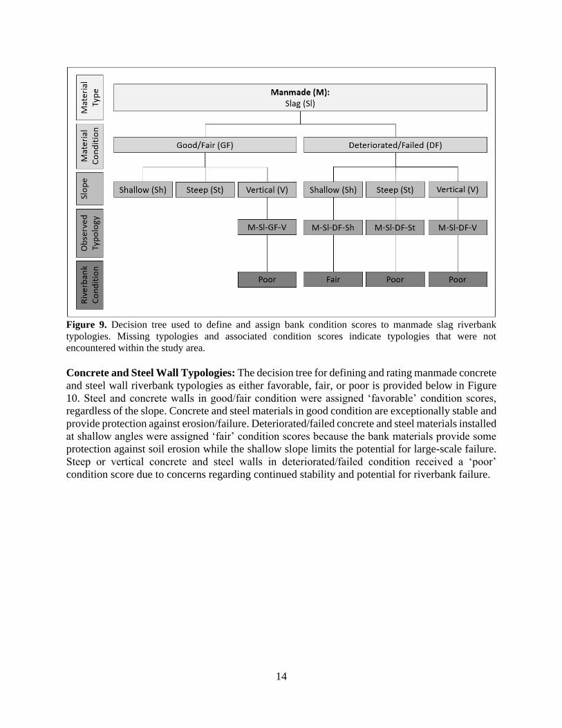
2.1.4.1.2 Manmade Riverbanks
Slag Typologies: The decision tree for defining and rating manmade slag riverbank typologies as
either favorable, fair, or poor is provided below in Figure 9. Shallow riverbanks composed of
deteriorated/failed slag received a ‘fair’ condition score. Slag is generally more resistant to erosion
than naturalized soils and provides protection against wave-action undercutting; however,
riverbanks composed of slag also have stability concerns when slopes are greater than 2H:1V.
Thus, steep and vertical riverbanks composed of slag received a ‘poor’ condition score, regardless
of condition (M-Sl-GF-V, M-Sl-DF-St, M-Sl-DF-V typologies; Figure 9).
14
Figure 9. Decision tree used to define and assign bank condition scores to manmade slag riverbank
typologies. Missing typologies and associated condition scores indicate typologies that were not
encountered within the study area.
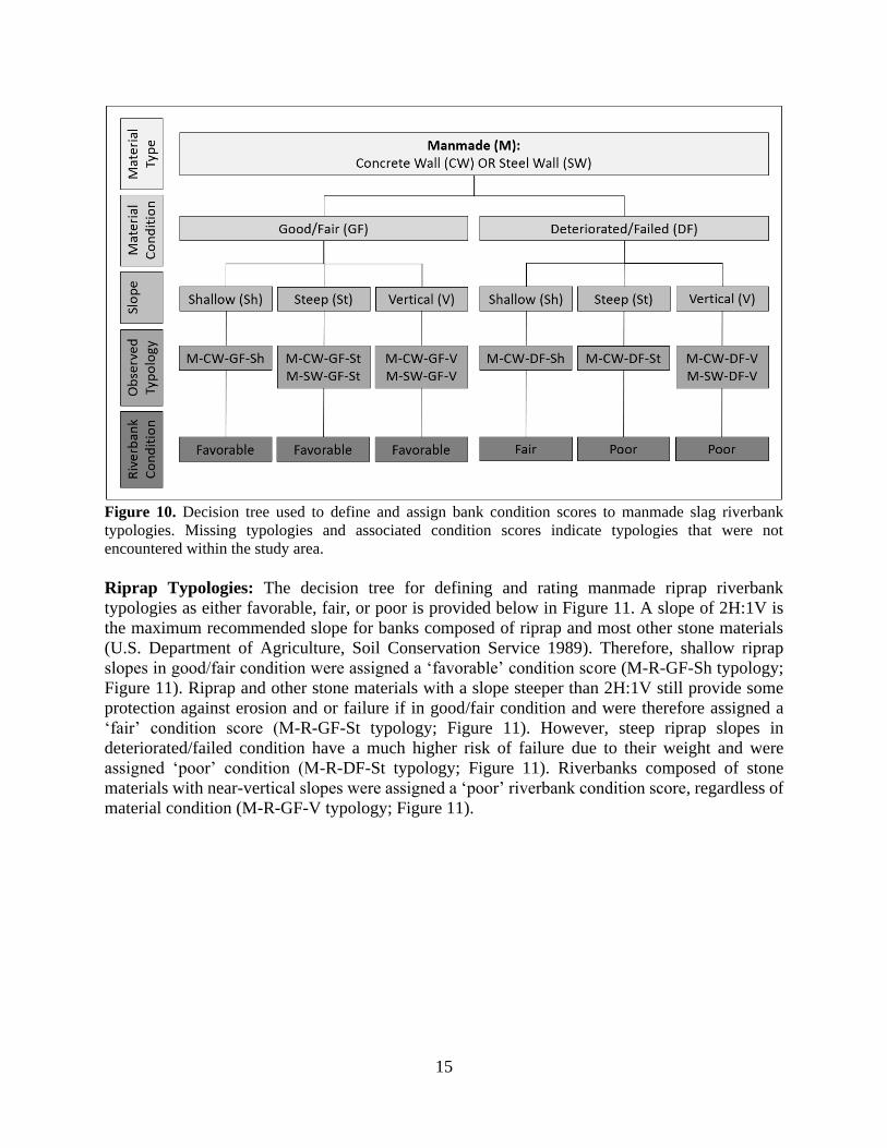
Concrete and Steel Wall Typologies: The decision tree for defining and rating manmade concrete
and steel wall riverbank typologies as either favorable, fair, or poor is provided below in Figure
10. Steel and concrete walls in good/fair condition were assigned ‘favorable’ condition scores,
regardless of the slope. Concrete and steel materials in good condition are exceptionally stable and
provide protection against erosion/failure. Deteriorated/failed concrete and steel materials installed
at shallow angles were assigned ‘fair’ condition scores because the bank materials provide some
protection against soil erosion while the shallow slope limits the potential for large-scale failure.
Steep or vertical concrete and steel walls in deteriorated/failed condition received a ‘poor’
condition score due to concerns regarding continued stability and potential for riverbank failure.
15
Figure 10. Decision tree used to define and assign bank condition scores to manmade slag riverbank
typologies. Missing typologies and associated condition scores indicate typologies that were not
encountered within the study area.
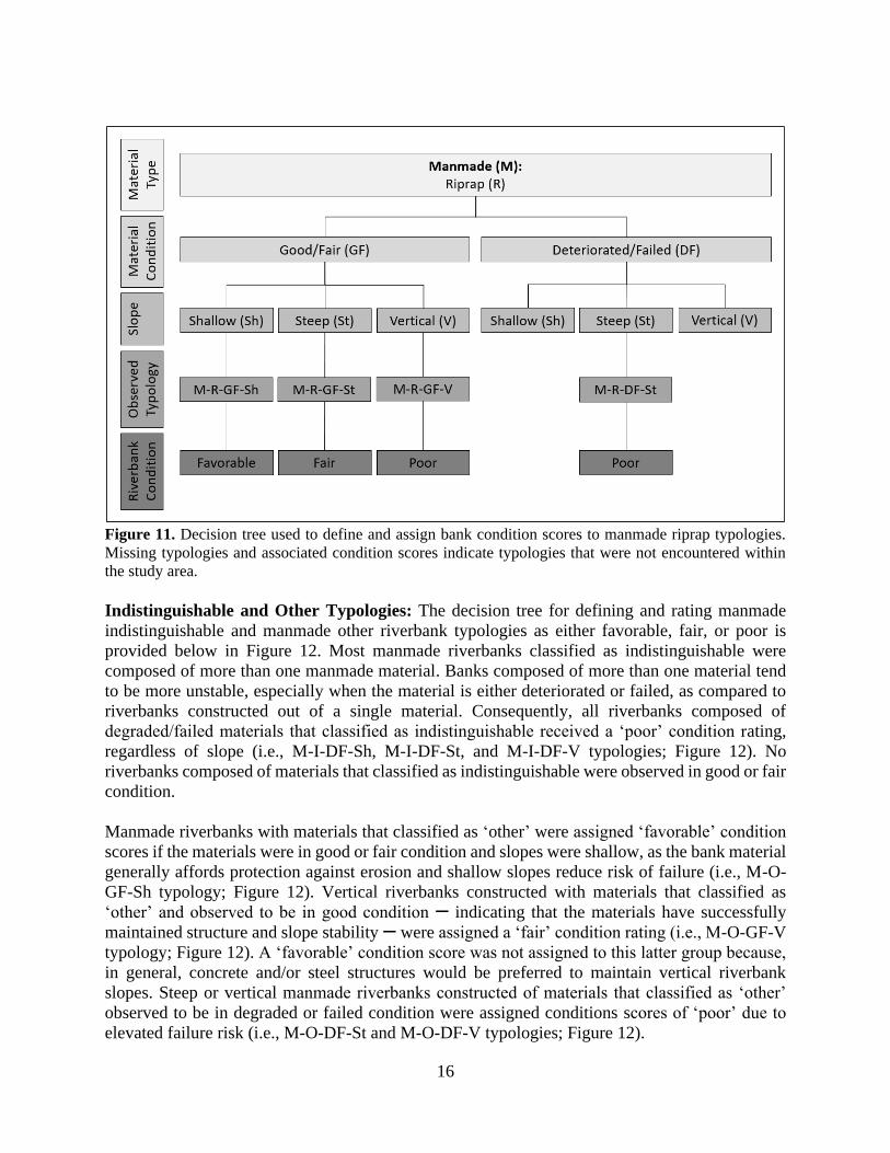
Riprap Typologies: The decision tree for defining and rating manmade riprap riverbank
typologies as either favorable, fair, or poor is provided below in Figure 11. A slope of 2H:1V is
the maximum recommended slope for banks composed of riprap and most other stone materials
(U.S. Department of Agriculture, Soil Conservation Service 1989). Therefore, shallow riprap
slopes in good/fair condition were assigned a ‘favorable’ condition score (M-R-GF-Sh typology;
Figure 11). Riprap and other stone materials with a slope steeper than 2H:1V still provide some
protection against erosion and or failure if in good/fair condition and were therefore assigned a
‘fair’ condition score (M-R-GF-St typology; Figure 11). However, steep riprap slopes in
deteriorated/failed condition have a much higher risk of failure due to their weight and were
assigned ‘poor’ condition (M-R-DF-St typology; Figure 11). Riverbanks composed of stone
materials with near-vertical slopes were assigned a ‘poor’ riverbank condition score, regardless of
material condition (M-R-GF-V typology; Figure 11).
16
Figure 11. Decision tree used to define and assign bank condition scores to manmade riprap typologies.
Missing typologies and associated condition scores indicate typologies that were not encountered within
the study area.
Indistinguishable and Other Typologies: The decision tree for defining and rating manmade
indistinguishable and manmade other riverbank typologies as either favorable, fair, or poor is
provided below in Figure 12. Most manmade riverbanks classified as indistinguishable were
composed of more than one manmade material. Banks composed of more than one material tend
to be more unstable, especially when the material is either deteriorated or failed, as compared to
riverbanks constructed out of a single material. Consequently, all riverbanks composed of
degraded/failed materials that classified as indistinguishable received a ‘poor’ condition rating,
regardless of slope (i.e., M-I-DF-Sh, M-I-DF-St, and M-I-DF-V typologies; Figure 12). No
riverbanks composed of materials that classified as indistinguishable were observed in good or fair
condition.
Manmade riverbanks with materials that classified as ‘other’ were assigned ‘favorable’ condition
scores if the materials were in good or fair condition and slopes were shallow, as the bank material
generally affords protection against erosion and shallow slopes reduce risk of failure (i.e., M-O-
GF-Sh typology; Figure 12). Vertical riverbanks constructed with materials that classified as
‘other’ and observed to be in good condition ꟷ indicating that the materials have successfully
maintained structure and slope stability ꟷ were assigned a ‘fair’ condition rating (i.e., M-O-GF-V
typology; Figure 12). A ‘favorable’ condition score was not assigned to this latter group because,
in general, concrete and/or steel structures would be preferred to maintain vertical riverbank
slopes. Steep or vertical manmade riverbanks constructed of materials that classified as ‘other’
observed to be in degraded or failed condition were assigned conditions scores of ‘poor’ due to
elevated failure risk (i.e., M-O-DF-St and M-O-DF-V typologies; Figure 12).
17
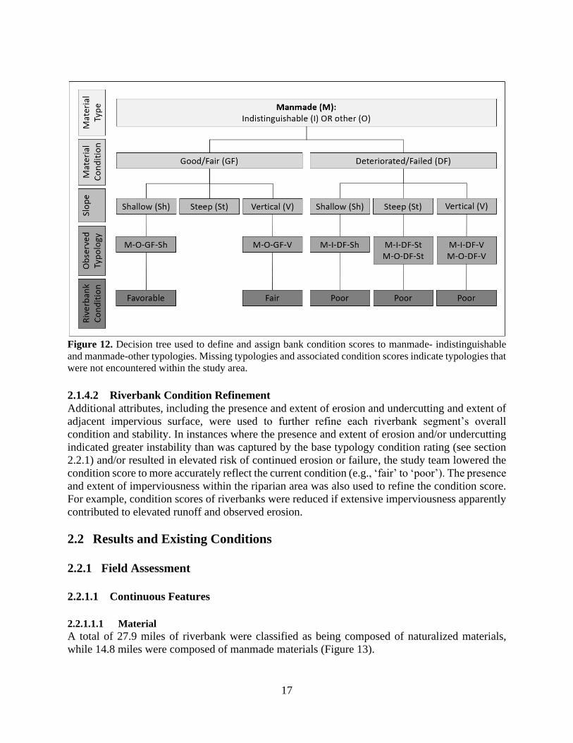
Figure 12. Decision tree used to define and assign bank condition scores to manmade- indistinguishable
and manmade-other typologies. Missing typologies and associated condition scores indicate typologies that
were not encountered within the study area.
2.1.4.2 Riverbank Condition Refinement
Additional attributes, including the presence and extent of erosion and undercutting and extent of
adjacent impervious surface, were used to further refine each riverbank segment’s overall
condition and stability. In instances where the presence and extent of erosion and/or undercutting
indicated greater instability than was captured by the base typology condition rating (see section
2.2.1) and/or resulted in elevated risk of continued erosion or failure, the study team lowered the
condition score to more accurately reflect the current condition (e.g., ‘fair’ to ‘poor’). The presence
and extent of imperviousness within the riparian area was also used to refine the condition score.
For example, condition scores of riverbanks were reduced if extensive imperviousness apparently
contributed to elevated runoff and observed erosion.
2.2 Results and Existing Conditions
2.2.1 Field Assessment
2.2.1.1 Continuous Features
2.2.1.1.1 Material
A total of 27.9 miles of riverbank were classified as being composed of naturalized materials,
while 14.8 miles were composed of manmade materials (Figure 13).
18
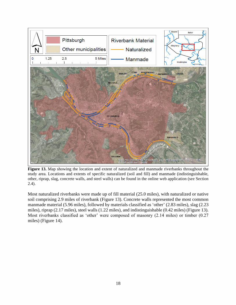
Figure 13. Map showing the location and extent of naturalized and manmade riverbanks throughout the
study area. Locations and extents of specific naturalized (soil and fill) and manmade (indistinguishable,
other, riprap, slag, concrete walls, and steel walls) can be found in the online web application (see Section
2.4).
Most naturalized riverbanks were made up of fill material (25.0 miles), with naturalized or native
soil comprising 2.9 miles of riverbank (Figure 13). Concrete walls represented the most common
manmade material (5.96 miles), followed by materials classified as ‘other’ (2.83 miles), slag (2.23
miles), riprap (2.17 miles), steel walls (1.22 miles), and indistinguishable (0.42 miles) (Figure 13).
Most riverbanks classified as ‘other’ were composed of masonry (2.14 miles) or timber (0.27
miles) (Figure 14).
19
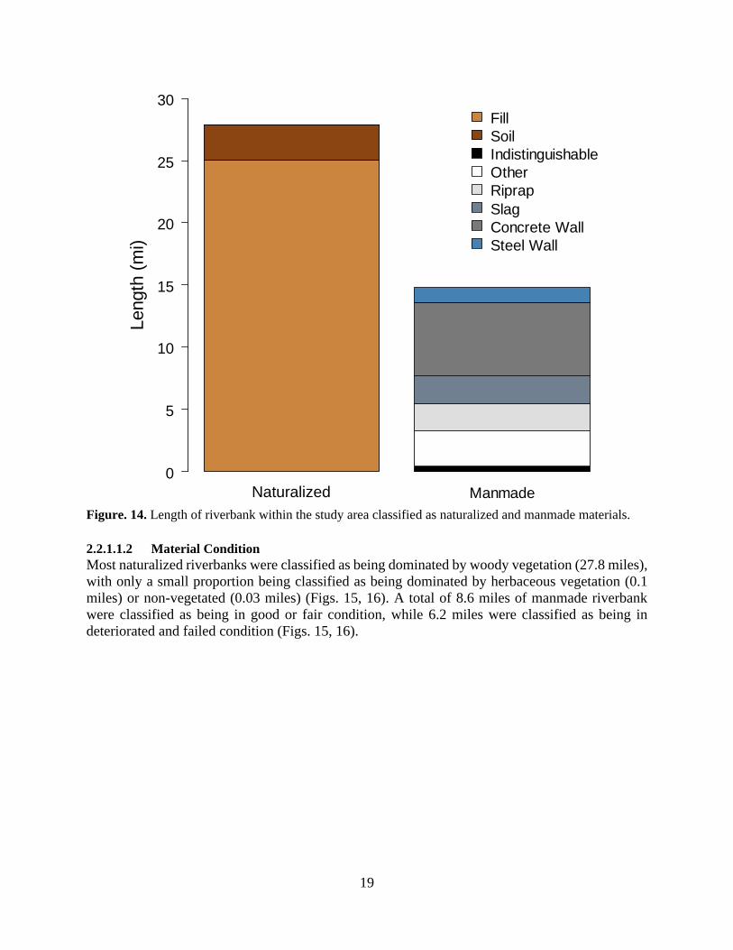
Figure. 14. Length of riverbank within the study area classified as naturalized and manmade materials.
2.2.1.1.2 Material Condition
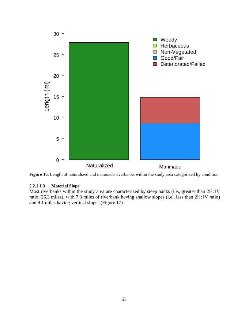
Most naturalized riverbanks were classified as being dominated by woody vegetation (27.8 miles),
with only a small proportion being classified as being dominated by herbaceous vegetation (0.1
miles) or non-vegetated (0.03 miles) (Figs. 15, 16). A total of 8.6 miles of manmade riverbank
were classified as being in good or fair condition, while 6.2 miles were classified as being in
deteriorated and failed condition (Figs. 15, 16).
Natural Manmade
Length
(m
i)
0
5
10
15
20
25
30
Fill
Soil
Indistinguishable
Other
Riprap
Slag
Concrete Wall
Steel Wall
Naturalized
20
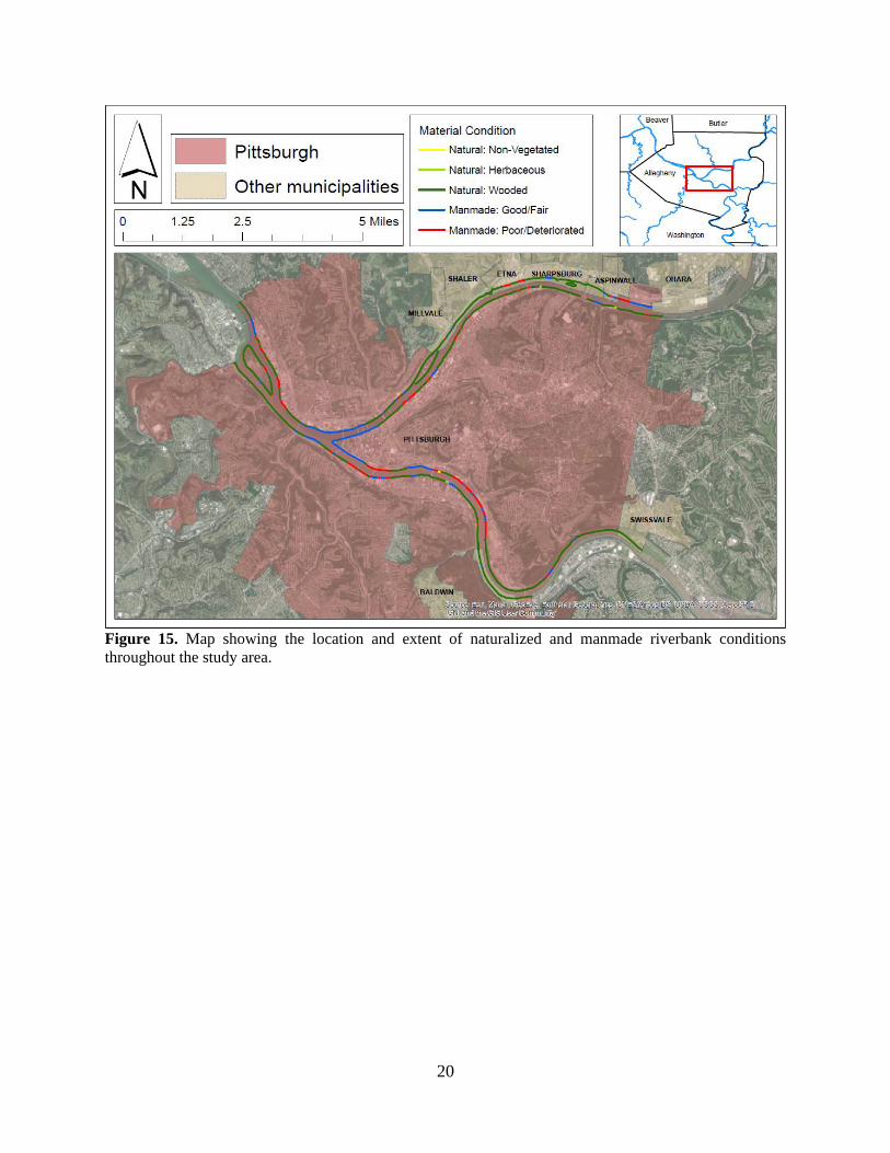
Figure 15. Map showing the location and extent of naturalized and manmade riverbank conditions
throughout the study area.
21
Figure 16. Length of naturalized and manmade riverbanks within the study area categorized by condition.
2.2.1.1.3 Material Slope
Most riverbanks within the study area are characterized by steep banks (i.e., greater than 2H:1V
ratio; 26.3 miles), with 7.3 miles of riverbank having shallow slopes (i.e., less than 2H:1V ratio)
and 9.1 miles having vertical slopes (Figure 17).
Natural Manmade
Length
(m
i)
0
5
10
15
20
25
30
Wooded
Grassy
Non-Vegetated
Good/Fair
Deteriorated/Failed
Naturalized
Woody Herbaceous Non-Vegetated Good/Fair Deteriorated/Failed
22
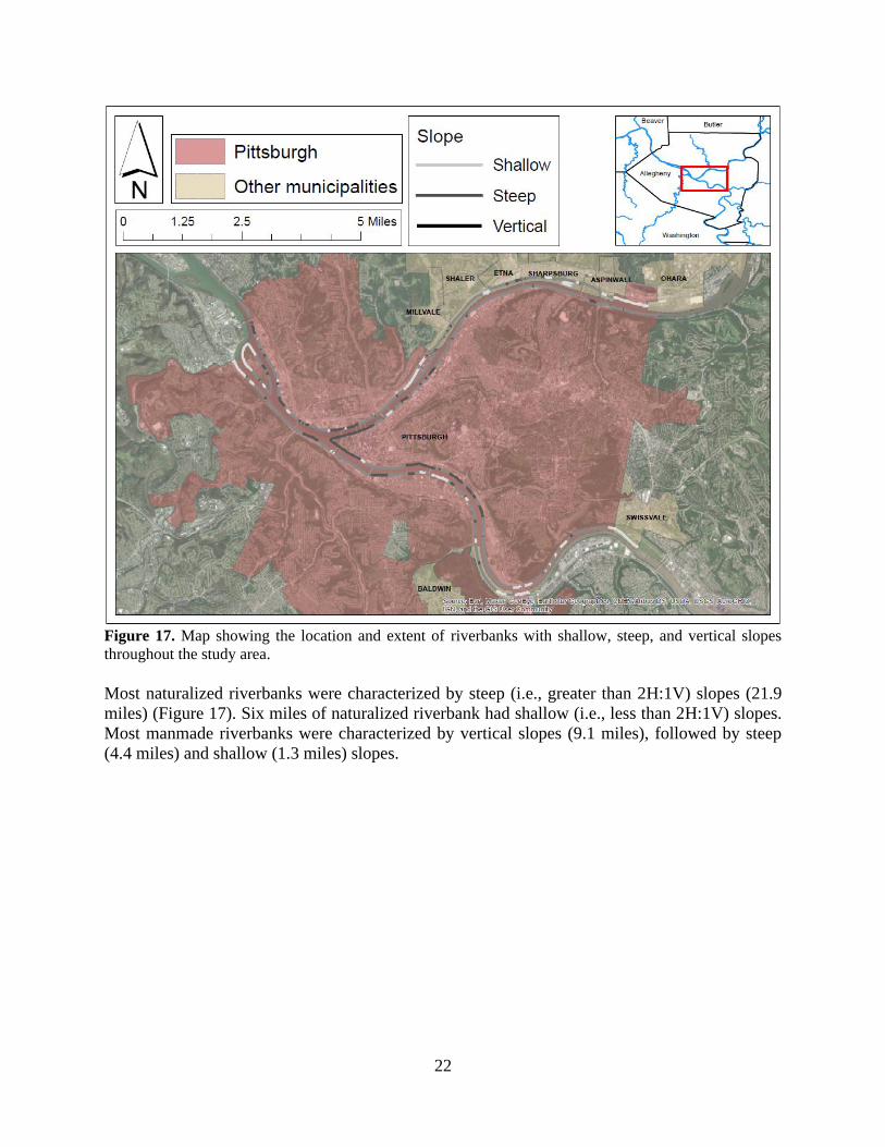
Figure 17. Map showing the location and extent of riverbanks with shallow, steep, and vertical slopes
throughout the study area.
Most naturalized riverbanks were characterized by steep (i.e., greater than 2H:1V) slopes (21.9
miles) (Figure 17). Six miles of naturalized riverbank had shallow (i.e., less than 2H:1V) slopes.
Most manmade riverbanks were characterized by vertical slopes (9.1 miles), followed by steep
(4.4 miles) and shallow (1.3 miles) slopes.
23
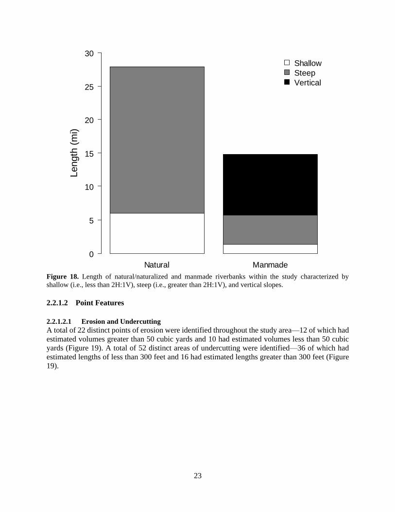
Figure 18. Length of natural/naturalized and manmade riverbanks within the study characterized by
shallow (i.e., less than 2H:1V), steep (i.e., greater than 2H:1V), and vertical slopes.
2.2.1.2 Point Features
2.2.1.2.1 Erosion and Undercutting
A total of 22 distinct points of erosion were identified throughout the study area—12 of which had
estimated volumes greater than 50 cubic yards and 10 had estimated volumes less than 50 cubic
yards (Figure 19). A total of 52 distinct areas of undercutting were identified—36 of which had
estimated lengths of less than 300 feet and 16 had estimated lengths greater than 300 feet (Figure
19).
Natural Manmade
Length
(m
i)
0
5
10
15
20
25
30
Shallow
Steep
Vertical
24
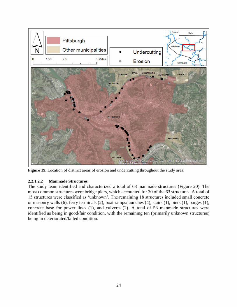
Figure 19. Location of distinct areas of erosion and undercutting throughout the study area.
2.2.1.2.2 Manmade Structures
The study team identified and characterized a total of 63 manmade structures (Figure 20). The
most common structures were bridge piers, which accounted for 30 of the 63 structures. A total of
15 structures were classified as ‘unknown’. The remaining 18 structures included small concrete
or masonry walls (6), ferry terminals (2), boat ramps/launches (4), stairs (1), piers (1), barges (1),
concrete base for power lines (1), and culverts (2). A total of 53 manmade structures were
identified as being in good/fair condition, with the remaining ten (primarily unknown structures)
being in deteriorated/failed condition.
25
Figure 20. Location of manmade structures identified during the field assessment and other culvert and
outlet locations provided by ALCOSAN.
2.2.2 GIS Assessment
2.2.2.1 Continuous Features
2.2.2.1.1 Riparian Imperviousness
A total of 17.0 miles of riverbank were associated with riparian areas with less than 33%
imperviousness, while 15.2 miles have riparian areas with between 33% and 66% imperviousness
and 10.6 miles have riparian areas with greater than 66% imperviousness (Figure 21).
26
Figure 21. Map showing percent imperviousness associated with riverbank segments throughout the study
area.
2.2.2.2 Point Features
2.2.2.2.1 Culverts and Outlets
A total of 162 culvert and other discharge outlets exist within the study area (Figure 20). These
data were provided by ALCOSAN and represent structures that are distinct from the manmade
structures identified and characterized during the field assessment (see Section 2.2.1.2.2).
2.2.3 Condition Assignment Thirty-one different typologies as defined by the continuous, field-based features (i.e., material
type, material condition, and slope) were observed throughout the study area, including seven
naturalized and 24 manmade typologies (Table 7). The most common typology was N-F-W-St
(i.e., naturalized-fill-woody-steep), which accounted for 21.5 miles (50.4%) of all riverbanks
within the study area. The most common manmade typology was M-CW-GF-V (i.e., manmade-
concrete wall-good/fair-vertical), which accounted for 4.4 riverbank miles (10.4%) (Table 7).
27
Table 7. The length and overall percentage of the 31 riverbank typologies encountered throughout the study
area. Typologies are defined by the three ongoing attributes collected in the field (i.e., bank material,
material condition, and slope. Typology notations reflect those presented in Figures 8 through 12.
Typology Notation Length %
Naturalized
Naturalized-Fill-Non-Vegetated-Steep N-F-Nv-St 0.03 0.07
Naturalized-Fill-Herbaceous-Shallow N-F-H-Sh 0.05 0.12
Naturalized-Fill-Woody-Shallow N-F-W-Sh 3.36 7.86
Naturalized-Fill-Herbaceous-Steep N-F-H-St 0.04 0.09
Naturalized-Fill-Woody-Steep N-F-W-St 21.5 50.4
Naturalized-Soil-Woody-Shallow N-So-W-Sh 2.59 6.06
Naturalized-Soil-Woody-Steep N-So-W-St 0.28 0.66
Manmade
Manmade-Slag-Good/Fair-Vertical M-Sl-GF-V 0.33 0.77
Manmade-Slag-Deteriorated/Failed-Shallow M-Sl-DF-Sh 0.07 0.16
Manmade-Slag-Deteriorated/Failed-Steep M-Sl-DF-St 1.20 2.81
Manmade-Slag-Deteriorated/Failed-Vertical M-Sl-DF-V 0.63 1.47
Manmade-Concrete Wall-Good/Fair-Shallow M-CW-GF-Sh 0.49 1.15
Manmade-Concrete Wall-Good/Fair-Steep M-CW-GF-St 0.02 0.05
Manmade-Concrete Wall-Good/Fair-Vertical M-CW-GF-V 4.44 10.4
Manmade-Concrete Wall-Deteriorated/Failed-Shallow M-CW-DF-Sh 0.25 0.59
Manmade-Concrete Wall-Deteriorated/Failed-Steep M-CW-DF-St 0.01 0.02
Manmade-Concrete Wall-Deteriorated/Failed-Vertical M-CW-DF-V 0.75 1.76
Manmade-Steel Wall-Good/Fair-Steep M-SW-GF-St 0.12 0.28
Manmade-Steel Wall-Good/Fair-Vertical M-SW-GF-V 1.00 2.34
Manmade-Steel Wall-Deteriorated/Failed-Vertical M-SW-DF-V 0.11 0.26
Manmade-Riprap-Good/Fair-Shallow M-R-GF-Sh 0.32 0.75
Manmade-Riprap-Good/Fair-Steep M-R-GF-St 1.30 3.04
Manmade-Riprap-Good/Fair-Vertical M-R-GF-V 0.10 0.23
Manmade-Riprap-Deteriorated/Failed-Steep M-R-DF-St 0.44 1.03
Manmade-Other-Good/Fair-Shallow M-O-GF-Sh 0.11 0.26
Manmade-Other-Good/Fair-Vertical M-O-GF-V 0.38 0.89
Manmade-Other-Deteriorated/Failed-Steep M-O-DF-St 1.08 2.53
Manmade-Other-Deteriorated/Failed-Vertical M-O-DF-V 1.27 2.97
Manmade-Indistinguishable-Deteriorated/Failed-Shallow M-I-DF-Sh 0.04 0.09
Manmade-Indistinguishable-Deteriorated/Failed-Steep M-I-DF-St 0.27 0.63
Manmade-Indistinguishable-Deteriorated/Failed/Vertical M-I-DF-V 0.11 0.26
These typology designations, along with information regarding the location and extent of erosion
and presence and extent of manmade structures within the channel and riparian areas, resulted in
a total 11.9 miles of riverbank receiving a ‘favorable’ condition assessment rating, 24.1 miles
receiving a ‘fair’ condition assessment rating, and 6.7 miles receiving a ‘poor’ condition
assessment rating (Figure 22).
28
Figure 22. Map of final riverbank condition assessment scores for the study area.
2.3 Published Map: Web Map Application The collected data was downloaded and prepared in ArcMap and ArcGIS Online to develop a Web
Map Application. Web Map Application is a product offered by ESRI that displays an online map
and various customizations. Upon completion of data editing in ArcMap, the layers were published
to ArcGIS Online and an application was created to display the characteristics. This interface is
live and accessible at the following location:
https://pittsburghpa.gov/innovation-performance/interactive-maps.
The Web Map Application can be used to visually assess riverbank conditions throughout the study
area and facilitate planning and management decisions, such as prioritizing areas for future
restoration actions.
2.3.1 Using the Web Map Application The application loads a ‘splash screen’ presenting a brief background on the project and how to
use the tools (‘widgets’) included in the application. The map contains several layers that can be
turned on or off using the Layer List widget.
29
Changes in the ongoing field characteristics (i.e., material, material condition, and slope) that
define changes in typology and individual riverbank segments, as well as point attributes (i.e.,
erosion, undercutting, and manmade structures) and associated data and photos are included on the
map as point features. The photos appear on the map approximately where they were taken from,
and a leader line points to the approximate location of the photo’s subject. Clicking on the photo
point activates a popup that displays observation attributes and a link to view the photo.
The ongoing characteristic observations from the field (i.e., material, material condition, and slope)
and GIS (i.e., riparian imperviousness) were used to categorize the riverbanks throughout the study
area. Riverbanks are defined by the ‘Shoreline’ layer from the US Army Corps of Engineers Army
Geospatial Center (AGC) Inland Electronic Navigation Charts (IENC). The IENC shoreline layer
was divided and attributed according to the recorded and defined attributes. Because there are
several attributions for ongoing characteristic observations, the shoreline layer is duplicated in the
Layer List to allow color-coded visualization of each attribute. Clicking on shoreline features
activates a popup that displays observation attributes.
Additional layers were added to the web application to provide additional context, including: bike
trails [bike trail map from Bike Pittsburgh (BikePGH)], major ALCOSAN discharges, the
approximate route of the USACE river survey vessel, the Riparian Zone (defined as a 75 foot
buffer of the IENC shoreline), City of Pittsburgh’s riverfront development overlay, City of
Pittsburgh Zoning, road lines (U.S. Geological Survey), IENC layers, municipal boundaries,
Allegheny County parcels (with a layer showing land owned by City of Pittsburgh), Allegheny
County parcels by ClassDesc (a County-determined category that categorizes land use into broad
categories), and aerial imagery base maps. These additional layers can enhance the utility of the
web map application to identify management priorities within the context of existing conditions
and City and stakeholder priorities.
The Add Data widget is available in the Web Map Application, which allows other published
geographic data or uploads to be temporarily added to the map. The USACE Pittsburgh District
Geospatial Section should be contacted if it is determined that additional layers are permanently
required. The Web Map Application does not contain an export function. The file geodatabase
containing observations and photos has been provided to the City of Pittsburgh.
3 Riverbank Stabilization Techniques and Applied Best Practices
Results of the riverbank assessment were incorporated into a Best Practices Guide designed to
assist with identifying the most effective riverbank stabilization and rehabilitation techniques for
each riverbank typology. The City of Pittsburgh, Riverlife (Pittsburgh-based non-profit
organization whose mission is community-led redevelopment of the City’s downtown riverfronts),
and the Pittsburgh District compiled pertinent existing reports and studies regarding Pittsburgh
riverbank and riparian ecology, and best practices for riverbank rehabilitation and stabilization for
urban riverbanks. Riverbank stabilization approaches summarized and included within this report
fall within the broad categories of bioengineering (i.e., engineering techniques that utilize nature-
based materials and processes to encourage riverbank stabilization and ecological diversity),
erosion and sediment control, stormwater management, and geotechnical techniques.
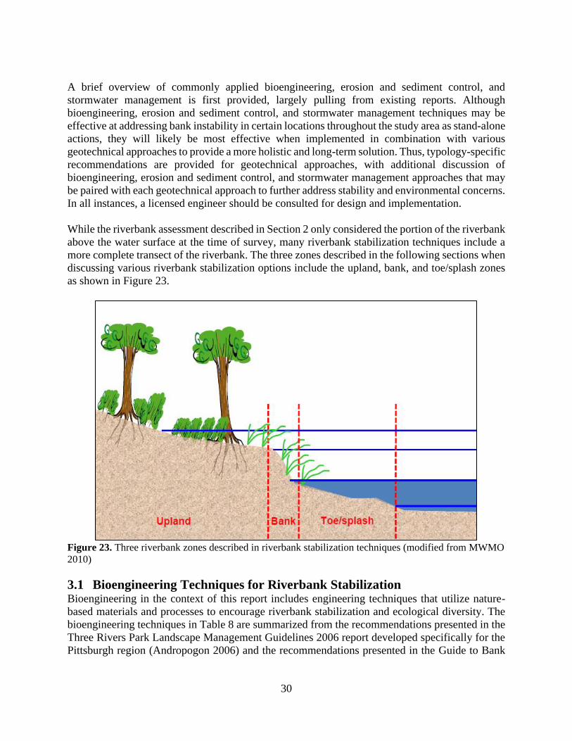
30
A brief overview of commonly applied bioengineering, erosion and sediment control, and
stormwater management is first provided, largely pulling from existing reports. Although
bioengineering, erosion and sediment control, and stormwater management techniques may be
effective at addressing bank instability in certain locations throughout the study area as stand-alone
actions, they will likely be most effective when implemented in combination with various
geotechnical approaches to provide a more holistic and long-term solution. Thus, typology-specific
recommendations are provided for geotechnical approaches, with additional discussion of
bioengineering, erosion and sediment control, and stormwater management approaches that may
be paired with each geotechnical approach to further address stability and environmental concerns.
In all instances, a licensed engineer should be consulted for design and implementation.
While the riverbank assessment described in Section 2 only considered the portion of the riverbank
above the water surface at the time of survey, many riverbank stabilization techniques include a
more complete transect of the riverbank. The three zones described in the following sections when
discussing various riverbank stabilization options include the upland, bank, and toe/splash zones
as shown in Figure 23.
Figure 23. Three riverbank zones described in riverbank stabilization techniques (modified from MWMO
2010)
3.1 Bioengineering Techniques for Riverbank Stabilization Bioengineering in the context of this report includes engineering techniques that utilize nature-
based materials and processes to encourage riverbank stabilization and ecological diversity. The
bioengineering techniques in Table 8 are summarized from the recommendations presented in the
Three Rivers Park Landscape Management Guidelines 2006 report developed specifically for the
Pittsburgh region (Andropogon 2006) and the recommendations presented in the Guide to Bank
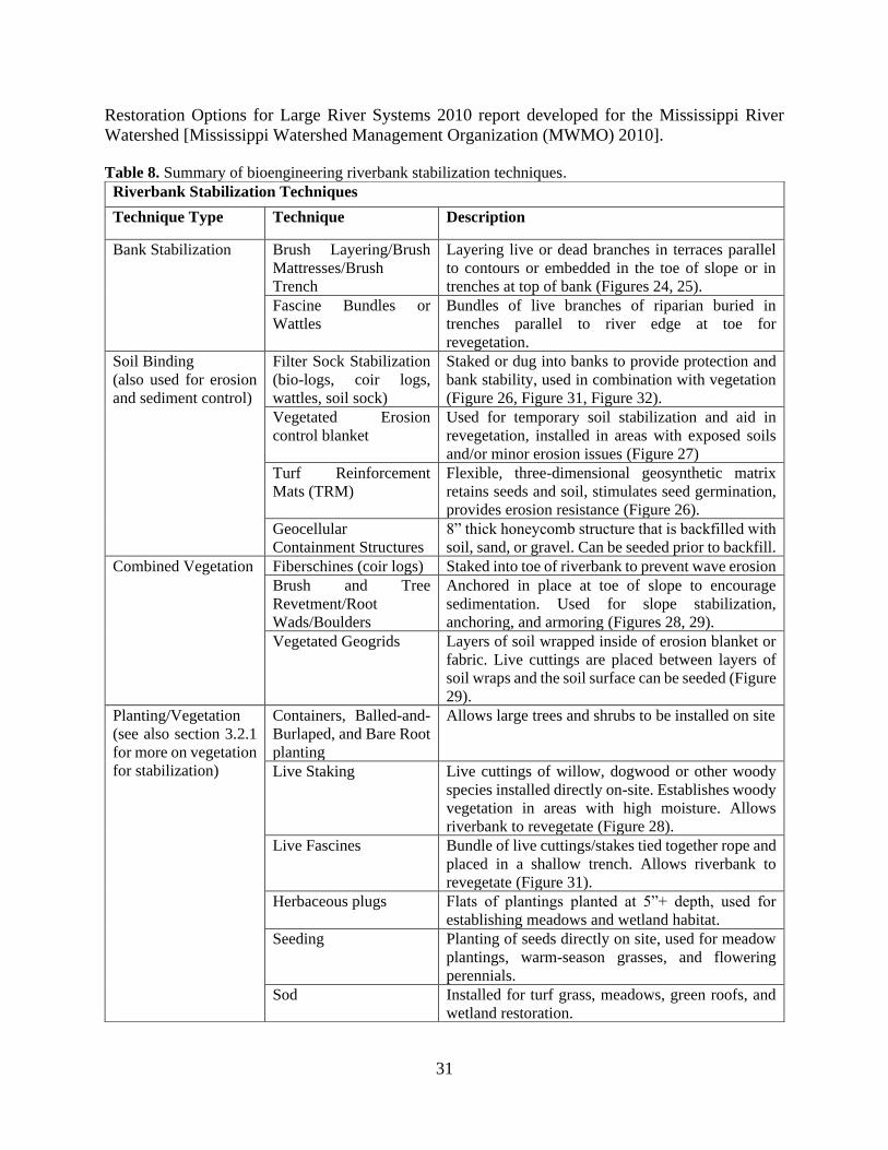
31
Restoration Options for Large River Systems 2010 report developed for the Mississippi River
Watershed [Mississippi Watershed Management Organization (MWMO) 2010].
Table 8. Summary of bioengineering riverbank stabilization techniques.
Riverbank Stabilization Techniques
Technique Type Technique Description
Bank Stabilization Brush Layering/Brush
Mattresses/Brush
Trench
Layering live or dead branches in terraces parallel
to contours or embedded in the toe of slope or in
trenches at top of bank (Figures 24, 25).
Fascine Bundles or
Wattles
Bundles of live branches of riparian buried in
trenches parallel to river edge at toe for
revegetation.
Soil Binding
(also used for erosion
and sediment control)
Filter Sock Stabilization
(bio-logs, coir logs,
wattles, soil sock)
Staked or dug into banks to provide protection and
bank stability, used in combination with vegetation
(Figure 26, Figure 31, Figure 32).
Vegetated Erosion
control blanket
Used for temporary soil stabilization and aid in
revegetation, installed in areas with exposed soils
and/or minor erosion issues (Figure 27) Turf Reinforcement
Mats (TRM)
Flexible, three-dimensional geosynthetic matrix
retains seeds and soil, stimulates seed germination,
provides erosion resistance (Figure 26).
Geocellular
Containment Structures
8” thick honeycomb structure that is backfilled with
soil, sand, or gravel. Can be seeded prior to backfill.
Combined Vegetation Fiberschines (coir logs) Staked into toe of riverbank to prevent wave erosion
Brush and Tree
Revetment/Root
Wads/Boulders
Anchored in place at toe of slope to encourage
sedimentation. Used for slope stabilization,
anchoring, and armoring (Figures 28, 29).
Vegetated Geogrids Layers of soil wrapped inside of erosion blanket or
fabric. Live cuttings are placed between layers of
soil wraps and the soil surface can be seeded (Figure
29).
Planting/Vegetation
(see also section 3.2.1
for more on vegetation
for stabilization)
Containers, Balled-and-
Burlaped, and Bare Root
planting
Allows large trees and shrubs to be installed on site
Live Staking Live cuttings of willow, dogwood or other woody
species installed directly on-site. Establishes woody
vegetation in areas with high moisture. Allows
riverbank to revegetate (Figure 28).
Live Fascines Bundle of live cuttings/stakes tied together rope and
placed in a shallow trench. Allows riverbank to
revegetate (Figure 31).
Herbaceous plugs Flats of plantings planted at 5”+ depth, used for
establishing meadows and wetland habitat.
Seeding Planting of seeds directly on site, used for meadow
plantings, warm-season grasses, and flowering
perennials.
Sod Installed for turf grass, meadows, green roofs, and
wetland restoration.
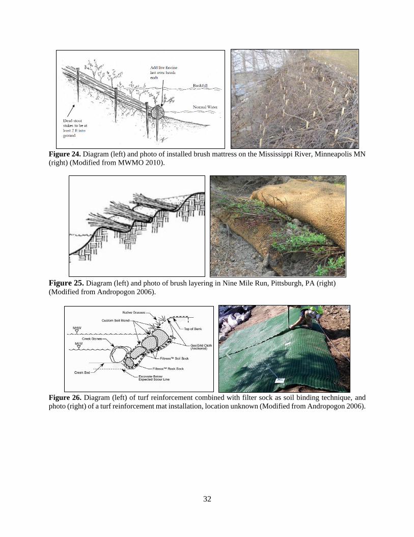
32
Figure 24. Diagram (left) and photo of installed brush mattress on the Mississippi River, Minneapolis MN
(right) (Modified from MWMO 2010).
Figure 25. Diagram (left) and photo of brush layering in Nine Mile Run, Pittsburgh, PA (right)
(Modified from Andropogon 2006).
Figure 26. Diagram (left) of turf reinforcement combined with filter sock as soil binding technique, and
photo (right) of a turf reinforcement mat installation, location unknown (Modified from Andropogon 2006).
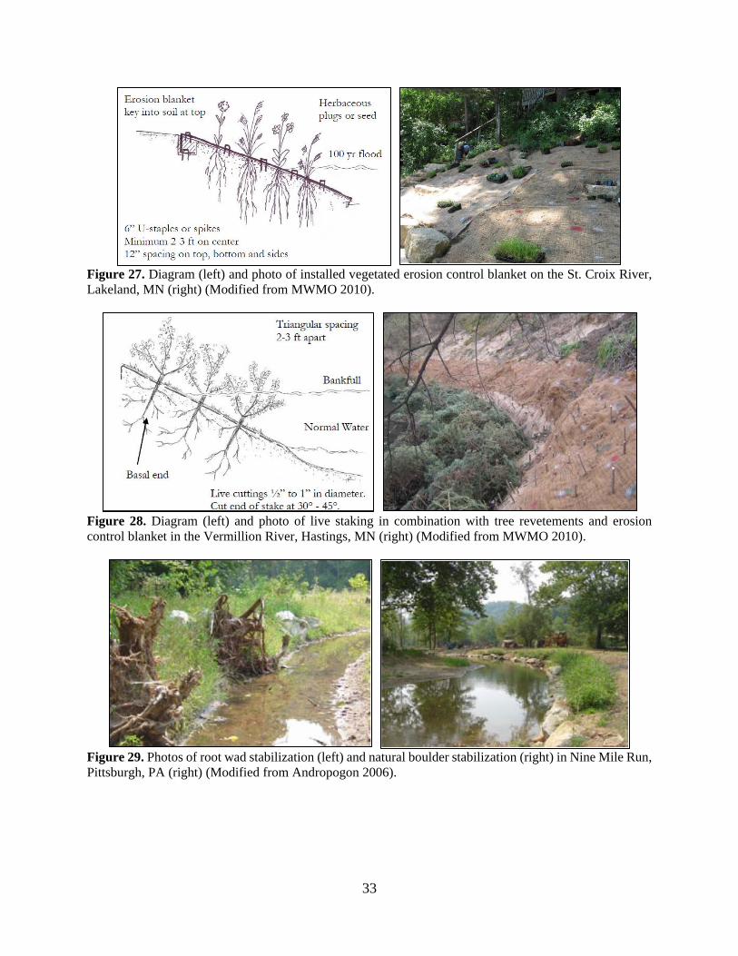
33
Figure 27. Diagram (left) and photo of installed vegetated erosion control blanket on the St. Croix River,
Lakeland, MN (right) (Modified from MWMO 2010).
Figure 28. Diagram (left) and photo of live staking in combination with tree revetements and erosion
control blanket in the Vermillion River, Hastings, MN (right) (Modified from MWMO 2010).
Figure 29. Photos of root wad stabilization (left) and natural boulder stabilization (right) in Nine Mile Run,
Pittsburgh, PA (right) (Modified from Andropogon 2006).
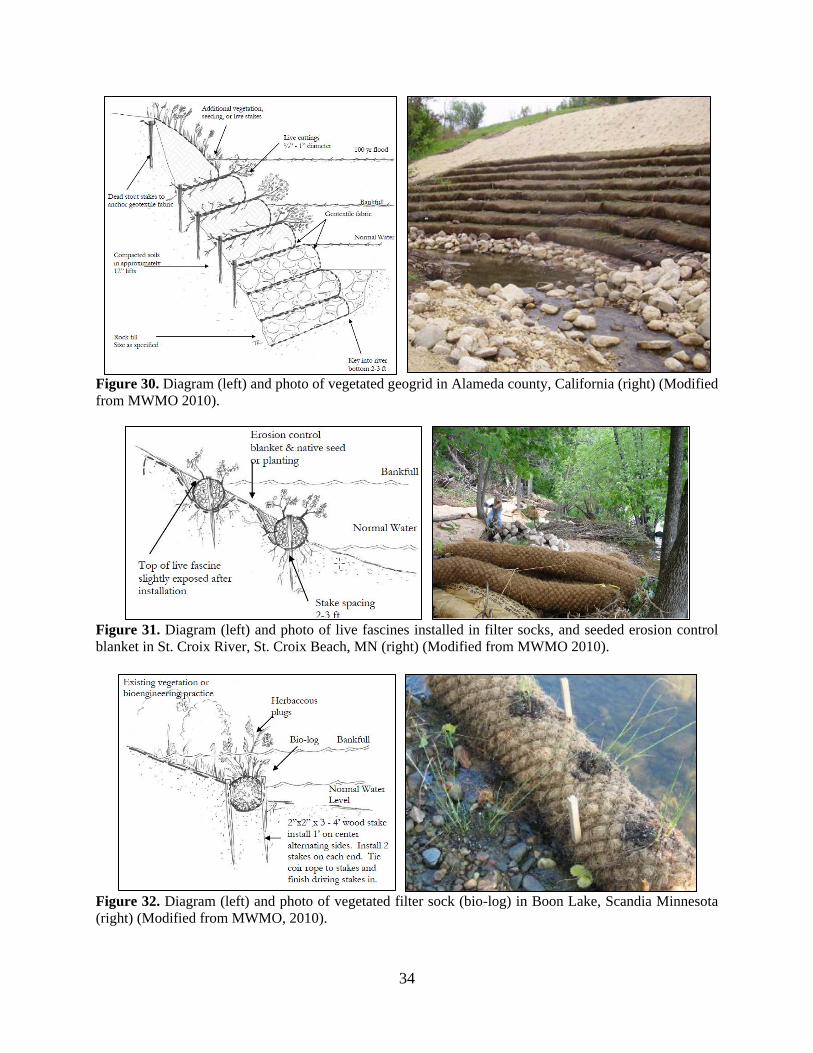
34
Figure 30. Diagram (left) and photo of vegetated geogrid in Alameda county, California (right) (Modified
from MWMO 2010).
Figure 31. Diagram (left) and photo of live fascines installed in filter socks, and seeded erosion control
blanket in St. Croix River, St. Croix Beach, MN (right) (Modified from MWMO 2010).
Figure 32. Diagram (left) and photo of vegetated filter sock (bio-log) in Boon Lake, Scandia Minnesota
(right) (Modified from MWMO, 2010).
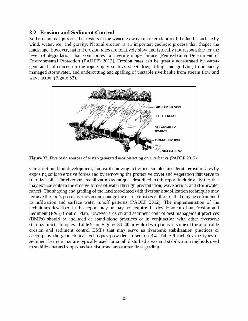
35
3.2 Erosion and Sediment Control Soil erosion is a process that results in the wearing away and degradation of the land’s surface by
wind, water, ice, and gravity. Natural erosion is an important geologic process that shapes the
landscape; however, natural erosion rates are relatively slow and typically not responsible for the
level of degradation that contributes to riverine slope failure [Pennsylvania Department of
Environmental Protection (PADEP) 2012]. Erosion rates can be greatly accelerated by water-
generated influences on the topography such as sheet flow, rilling, and gullying from poorly
managed stormwater, and undercutting and spalling of unstable riverbanks from stream flow and
wave action (Figure 33).
Figure 33. Five main sources of water-generated erosion acting on riverbanks (PADEP 2012)
Construction, land development, and earth-moving activities can also accelerate erosion rates by
exposing soils to erosive forces and by removing the protective cover and vegetation that serve to
stabilize soils. The riverbank stabilization techniques described in this report include activities that
may expose soils to the erosive forces of water through precipitation, wave action, and stormwater
runoff. The shaping and grading of the land associated with riverbank stabilization techniques may
remove the soil’s protective cover and change the characteristics of the soil that may be detrimental
to infiltration and surface water runoff patterns (PADEP 2012). The implementation of the
techniques described in this report may or may not require the development of an Erosion and
Sediment (E&S) Control Plan, however erosion and sediment control best management practices
(BMPs) should be included as stand-alone practices or in conjunction with other riverbank
stabilization techniques. Table 9 and Figures 34–40 provide descriptions of some of the applicable
erosion and sediment control BMPs that may serve as riverbank stabilization practices or
accompany the geotechnical techniques provided in section 3.4. Table 9 includes the types of
sediment barriers that are typically used for small disturbed areas and stabilization methods used
to stabilize natural slopes and/or disturbed areas after final grading.
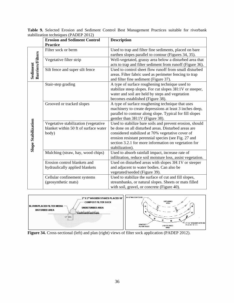
36
Table 9. Selected Erosion and Sediment Control Best Management Practices suitable for riverbank
stabilization techniques (PADEP 2012)
Erosion and Sediment Control
Practice
Description
Sed
imen
t
Barr
iers
/Fil
ters
Filter sock or berm Used to trap and filter fine sediments, placed on bare
earthen slopes parallel to contour (Figures 34, 35).
Vegetative filter strip Well-vegetated, grassy area below a disturbed area that
acts to trap and filter sediment from runoff (Figure 36).
Silt fence and super silt fence Used to control sheet flow runoff from small disturbed
areas. Filter fabric used as perimeter fencing to trap
and filter fine sediment (Figure 37).
Slo
pe
Sta
bil
izati
on
Stair-step grading A type of surface roughening technique used to
stabilize steep slopes. For cut slopes 3H:1V or steeper,
water and soil are held by steps and vegetation
becomes established (Figure 38).
Grooved or tracked slopes A type of surface roughening technique that uses
machinery to create depressions at least 3 inches deep,
parallel to contour along slope. Typical for fill slopes
gentler than 3H:1V (Figure 38).
Vegetative stabilization (vegetative
blanket within 50 ft of surface water
body)
Used to stabilize bare soils and prevent erosion, should
be done on all disturbed areas. Disturbed areas are
considered stabilized at 70% vegetative cover of
erosion resistant perennial species (see Fig. 27 and
section 3.2.1 for more information on vegetation for
stabilization).
Mulching (straw, hay, wood chips) Used to absorb rainfall impact, increase rate of
infiltration, reduce soil moisture loss, assist vegetation.
Erosion control blankets and
hydraulically applied blankets
Used on disturbed areas with slopes 3H:1V or steeper
and adjacent to water bodies. Can also be
vegetated/seeded (Figure 39).
Cellular confinement systems
(geosynthetic mats)
Used to stabilize the surface of cut and fill slopes,
streambanks, or natural slopes. Sheets or mats filled
with soil, gravel, or concrete (Figure 40).
Figure 34. Cross-sectional (left) and plan (right) views of filter sock application (PADEP 2012).
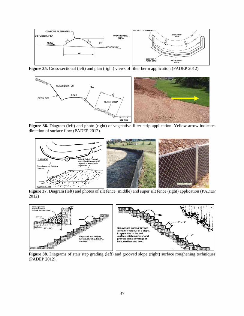
37
Figure 35. Cross-sectional (left) and plan (right) views of filter berm application (PADEP 2012)
Figure 36. Diagram (left) and photo (right) of vegetative filter strip application. Yellow arrow indicates
direction of surface flow (PADEP 2012).
Figure 37. Diagram (left) and photos of silt fence (middle) and super silt fence (right) application (PADEP
2012)
Figure 38. Diagrams of stair step grading (left) and grooved slope (right) surface roughening techniques
(PADEP 2012).
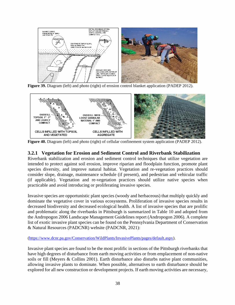
38
Figure 39. Diagram (left) and photo (right) of erosion control blanket application (PADEP 2012).
Figure 40. Diagram (left) and photo (right) of cellular confinement system application (PADEP 2012).
3.2.1 Vegetation for Erosion and Sediment Control and Riverbank Stabilization Riverbank stabilization and erosion and sediment control techniques that utilize vegetation are
intended to protect against soil erosion, improve riparian and floodplain function, promote plant
species diversity, and improve natural habitat. Vegetation and re-vegetation practices should
consider slope, drainage, maintenance schedule (if present), and pedestrian and vehicular traffic
(if applicable). Vegetation and re-vegetation practices should utilize native species when
practicable and avoid introducing or proliferating invasive species.
Invasive species are opportunistic plant species (woody and herbaceous) that multiply quickly and
dominate the vegetative cover in various ecosystems. Proliferation of invasive species results in
decreased biodiversity and decreased ecological health. A list of invasive species that are prolific
and problematic along the riverbanks in Pittsburgh is summarized in Table 10 and adopted from
the Andropogon 2006 Landscape Management Guidelines report (Andropogon 2006). A complete
list of exotic invasive plant species can be found on the Pennsylvania Department of Conservation
& Natural Resources (PADCNR) website (PADCNR, 2021):
(https://www.dcnr.pa.gov/Conservation/WildPlants/InvasivePlants/pages/default.aspx).
Invasive plant species are found to be the most prolific in sections of the Pittsburgh riverbanks that
have high degrees of disturbance from earth moving activities or from emplacement of non-native
soils or fill (Meyers & Collins 2001). Earth disturbance also disturbs native plant communities,
allowing invasive plants to dominate. When possible, alternatives to earth disturbance should be
explored for all new construction or development projects. If earth moving activities are necessary,
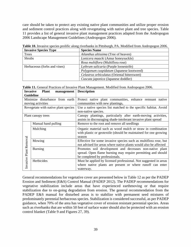
39
care should be taken to protect any existing native plant communities and utilize proper erosion
and sediment control practices along with revegetating with native plant and tree species. Table
11 provides a list of general invasive plant management practices adapted from the Andropogon
2006 Landscape Management Guidelines (Andropogon 2006).
Table 10. Invasive species prolific along riverbanks in Pittsburgh, PA. Modified from Andropogon 2006.
Invasive Species Type Species Name
Trees Ailanthus altissima (Tree of heaven)
Shrubs Lonicera maacki (Amur honeysuckle)
Rosa multiflora (Multiflora rose)
Herbaceous (forbs and vines) Lythrum salicaria (Purple loosestrife)
Polygonum cuspidatum (Japanese knotweed)
Celastrus orbiculatus (Oriental bittersweet)
Cuscuta japonica (Japanese doddler)
Table 11. General Practices of Invasive Plant Management. Modified from Andropogon 2006.
Invasive Plant management
Guideline
Description
Minimize disturbance from earth
moving activities
Protect native plant communities, enhance remnant native
communities with new plantings,
Revegetate with native plant species Use a native species list matched to the specific habitat. Avoid
non-native species.
Plant canopy trees Canopy plantings, particularly after earth-moving activities,
assists in discouraging shade-intolerant invasive plant spread
Invas
ive
Pla
nt
Rem
ov
al
Manual hand pulling Remove to the root and remove all seedlings
Mulching Organic material such as wood mulch or straw in combination
with plastic or geotextile (should be maintained for one growing
season
Mowing Effective for some invasive species such as multiflora rose, but
not advised for areas where native plants would also be affected
Burning Promotes soil development and decreases non-native plant
spread. Open flame burning may require permitting and should
be completed by professionals.
Herbicides Must be applied by licensed professional. Not suggested in areas
where native plants are present or where runoff can enter
waterway.
General recommendations for vegetative cover are presented below in Table 12 as per the PADEP
Erosion and Sediment (E&S) Control Manual (PADEP 2012). The PADEP recommendations for
vegetative stabilization include areas that have experienced earthmoving or that require
stabilization due to on-going degradation from erosion. The general recommendation from the
PADEP E&S manual for disturbed areas is to stabilize with permanent seed mixtures of
predominately perennial herbaceous species. Stabilization is considered successful, as per PADEP
guidance, when 70% of the area has vegetative cover of erosion resistant perennial species. Areas
such as riverbanks that are within 50 feet of surface water should also be protected with an erosion
control blanket (Table 9 and Figures 27, 39).
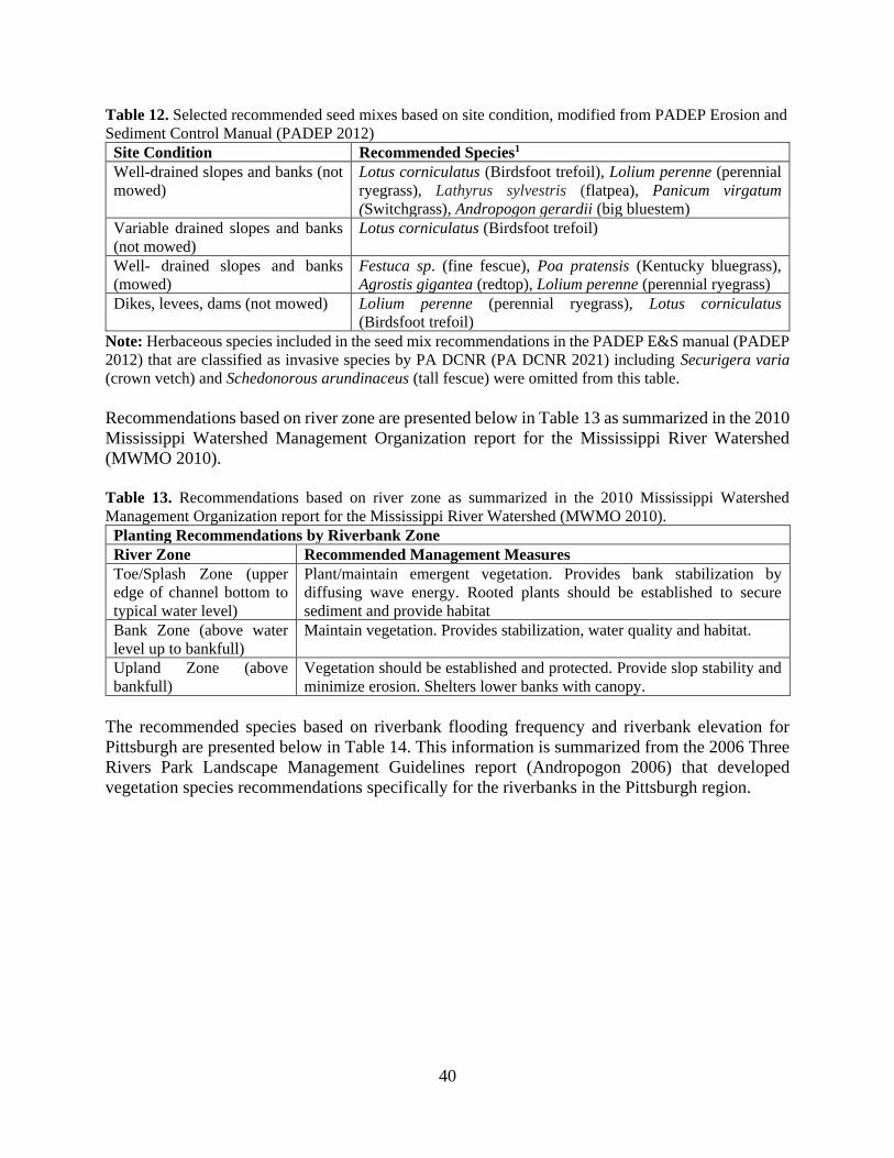
40
Table 12. Selected recommended seed mixes based on site condition, modified from PADEP Erosion and
Sediment Control Manual (PADEP 2012)
Site Condition Recommended Species1
Well-drained slopes and banks (not
mowed)
Lotus corniculatus (Birdsfoot trefoil), Lolium perenne (perennial
ryegrass), Lathyrus sylvestris (flatpea), Panicum virgatum
(Switchgrass), Andropogon gerardii (big bluestem)
Variable drained slopes and banks
(not mowed)
Lotus corniculatus (Birdsfoot trefoil)
Well- drained slopes and banks
(mowed)
Festuca sp. (fine fescue), Poa pratensis (Kentucky bluegrass),
Agrostis gigantea (redtop), Lolium perenne (perennial ryegrass)
Dikes, levees, dams (not mowed) Lolium perenne (perennial ryegrass), Lotus corniculatus
(Birdsfoot trefoil)
Note: Herbaceous species included in the seed mix recommendations in the PADEP E&S manual (PADEP
2012) that are classified as invasive species by PA DCNR (PA DCNR 2021) including Securigera varia
(crown vetch) and Schedonorous arundinaceus (tall fescue) were omitted from this table.
Recommendations based on river zone are presented below in Table 13 as summarized in the 2010
Mississippi Watershed Management Organization report for the Mississippi River Watershed
(MWMO 2010).
Table 13. Recommendations based on river zone as summarized in the 2010 Mississippi Watershed
Management Organization report for the Mississippi River Watershed (MWMO 2010).
Planting Recommendations by Riverbank Zone
River Zone Recommended Management Measures
Toe/Splash Zone (upper
edge of channel bottom to
typical water level)
Plant/maintain emergent vegetation. Provides bank stabilization by
diffusing wave energy. Rooted plants should be established to secure
sediment and provide habitat
Bank Zone (above water
level up to bankfull)
Maintain vegetation. Provides stabilization, water quality and habitat.
Upland Zone (above
bankfull)
Vegetation should be established and protected. Provide slop stability and
minimize erosion. Shelters lower banks with canopy.
The recommended species based on riverbank flooding frequency and riverbank elevation for
Pittsburgh are presented below in Table 14. This information is summarized from the 2006 Three
Rivers Park Landscape Management Guidelines report (Andropogon 2006) that developed
vegetation species recommendations specifically for the riverbanks in the Pittsburgh region.
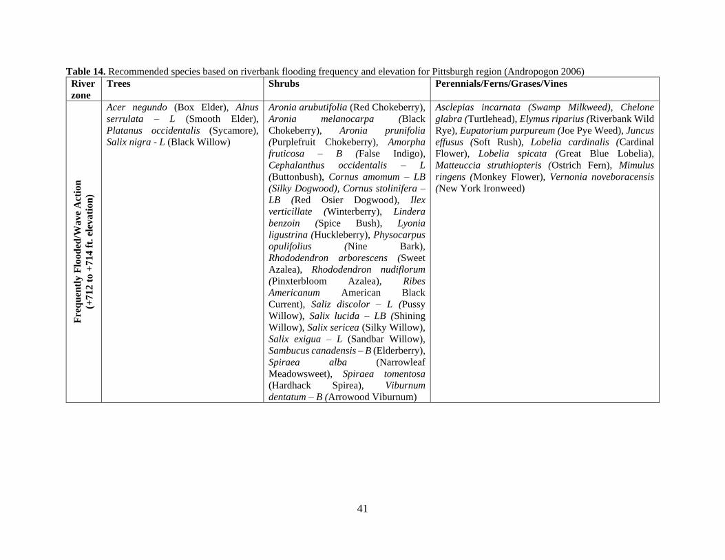
41
Table 14. Recommended species based on riverbank flooding frequency and elevation for Pittsburgh region (Andropogon 2006)
River
zone
Trees Shrubs Perennials/Ferns/Grases/Vines F
req
uen
tly
Flo
od
ed/W
ave
Act
ion
(+71
2 t
o +
714 f
t. e
leva
tion
)
Acer negundo (Box Elder), Alnus
serrulata – L (Smooth Elder),
Platanus occidentalis (Sycamore),
Salix nigra - L (Black Willow)
Aronia arubutifolia (Red Chokeberry),
Aronia melanocarpa (Black
Chokeberry), Aronia prunifolia
(Purplefruit Chokeberry), Amorpha
fruticosa – B (False Indigo),
Cephalanthus occidentalis – L
(Buttonbush), Cornus amomum – LB
(Silky Dogwood), Cornus stolinifera –
LB (Red Osier Dogwood), Ilex
verticillate (Winterberry), Lindera
benzoin (Spice Bush), Lyonia
ligustrina (Huckleberry), Physocarpus
opulifolius (Nine Bark),
Rhododendron arborescens (Sweet
Azalea), Rhododendron nudiflorum
(Pinxterbloom Azalea), Ribes
Americanum American Black
Current), Saliz discolor – L (Pussy
Willow), Salix lucida – LB (Shining
Willow), Salix sericea (Silky Willow),
Salix exigua – L (Sandbar Willow),
Sambucus canadensis – B (Elderberry),
Spiraea alba (Narrowleaf
Meadowsweet), Spiraea tomentosa
(Hardhack Spirea), Viburnum
dentatum – B (Arrowood Viburnum)
Asclepias incarnata (Swamp Milkweed), Chelone
glabra (Turtlehead), Elymus riparius (Riverbank Wild
Rye), Eupatorium purpureum (Joe Pye Weed), Juncus
effusus (Soft Rush), Lobelia cardinalis (Cardinal
Flower), Lobelia spicata (Great Blue Lobelia),
Matteuccia struthiopteris (Ostrich Fern), Mimulus
ringens (Monkey Flower), Vernonia noveboracensis
(New York Ironweed)
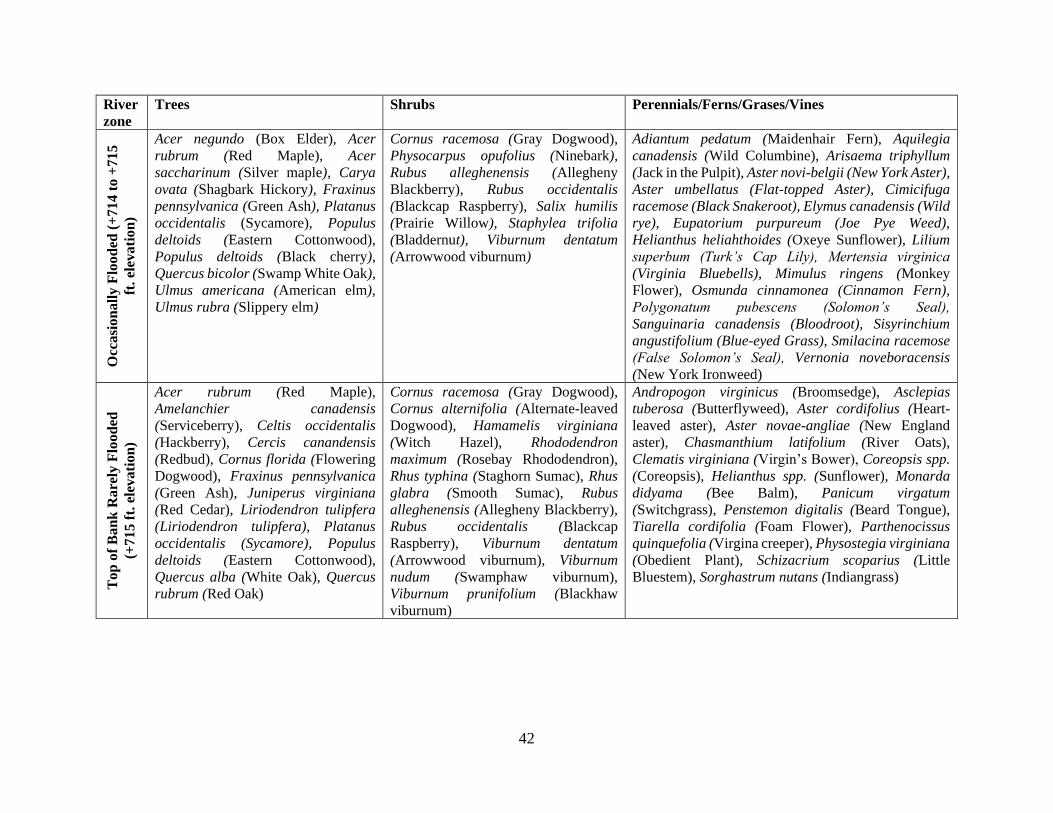
42
River
zone
Trees Shrubs Perennials/Ferns/Grases/Vines O
ccasi
on
all
y F
loo
ded
(+
714
to
+715
ft.
elev
ati
on
) Acer negundo (Box Elder), Acer
rubrum (Red Maple), Acer
saccharinum (Silver maple), Carya
ovata (Shagbark Hickory), Fraxinus
pennsylvanica (Green Ash), Platanus
occidentalis (Sycamore), Populus
deltoids (Eastern Cottonwood),
Populus deltoids (Black cherry),
Quercus bicolor (Swamp White Oak),
Ulmus americana (American elm),
Ulmus rubra (Slippery elm)
Cornus racemosa (Gray Dogwood),
Physocarpus opufolius (Ninebark),
Rubus alleghenensis (Allegheny
Blackberry), Rubus occidentalis
(Blackcap Raspberry), Salix humilis
(Prairie Willow), Staphylea trifolia
(Bladdernut), Viburnum dentatum
(Arrowwood viburnum)
Adiantum pedatum (Maidenhair Fern), Aquilegia
canadensis (Wild Columbine), Arisaema triphyllum
(Jack in the Pulpit), Aster novi-belgii (New York Aster),
Aster umbellatus (Flat-topped Aster), Cimicifuga
racemose (Black Snakeroot), Elymus canadensis (Wild
rye), Eupatorium purpureum (Joe Pye Weed),
Helianthus heliahthoides (Oxeye Sunflower), Lilium
superbum (Turk’s Cap Lily), Mertensia virginica
(Virginia Bluebells), Mimulus ringens (Monkey
Flower), Osmunda cinnamonea (Cinnamon Fern),
Polygonatum pubescens (Solomon’s Seal),
Sanguinaria canadensis (Bloodroot), Sisyrinchium
angustifolium (Blue-eyed Grass), Smilacina racemose
(False Solomon’s Seal), Vernonia noveboracensis
(New York Ironweed)
To
p o
f B
an
k R
are
ly F
lood
ed
(+7
15
ft.
ele
vati
on
)
Acer rubrum (Red Maple),
Amelanchier canadensis
(Serviceberry), Celtis occidentalis
(Hackberry), Cercis canandensis
(Redbud), Cornus florida (Flowering
Dogwood), Fraxinus pennsylvanica
(Green Ash), Juniperus virginiana
(Red Cedar), Liriodendron tulipfera
(Liriodendron tulipfera), Platanus
occidentalis (Sycamore), Populus
deltoids (Eastern Cottonwood),
Quercus alba (White Oak), Quercus
rubrum (Red Oak)
Cornus racemosa (Gray Dogwood),
Cornus alternifolia (Alternate-leaved
Dogwood), Hamamelis virginiana
(Witch Hazel), Rhododendron
maximum (Rosebay Rhododendron),
Rhus typhina (Staghorn Sumac), Rhus
glabra (Smooth Sumac), Rubus
alleghenensis (Allegheny Blackberry),
Rubus occidentalis (Blackcap
Raspberry), Viburnum dentatum
(Arrowwood viburnum), Viburnum
nudum (Swamphaw viburnum),
Viburnum prunifolium (Blackhaw
viburnum)
Andropogon virginicus (Broomsedge), Asclepias
tuberosa (Butterflyweed), Aster cordifolius (Heart-
leaved aster), Aster novae-angliae (New England
aster), Chasmanthium latifolium (River Oats),
Clematis virginiana (Virgin’s Bower), Coreopsis spp.
(Coreopsis), Helianthus spp. (Sunflower), Monarda
didyama (Bee Balm), Panicum virgatum
(Switchgrass), Penstemon digitalis (Beard Tongue),
Tiarella cordifolia (Foam Flower), Parthenocissus
quinquefolia (Virgina creeper), Physostegia virginiana
(Obedient Plant), Schizacrium scoparius (Little
Bluestem), Sorghastrum nutans (Indiangrass)
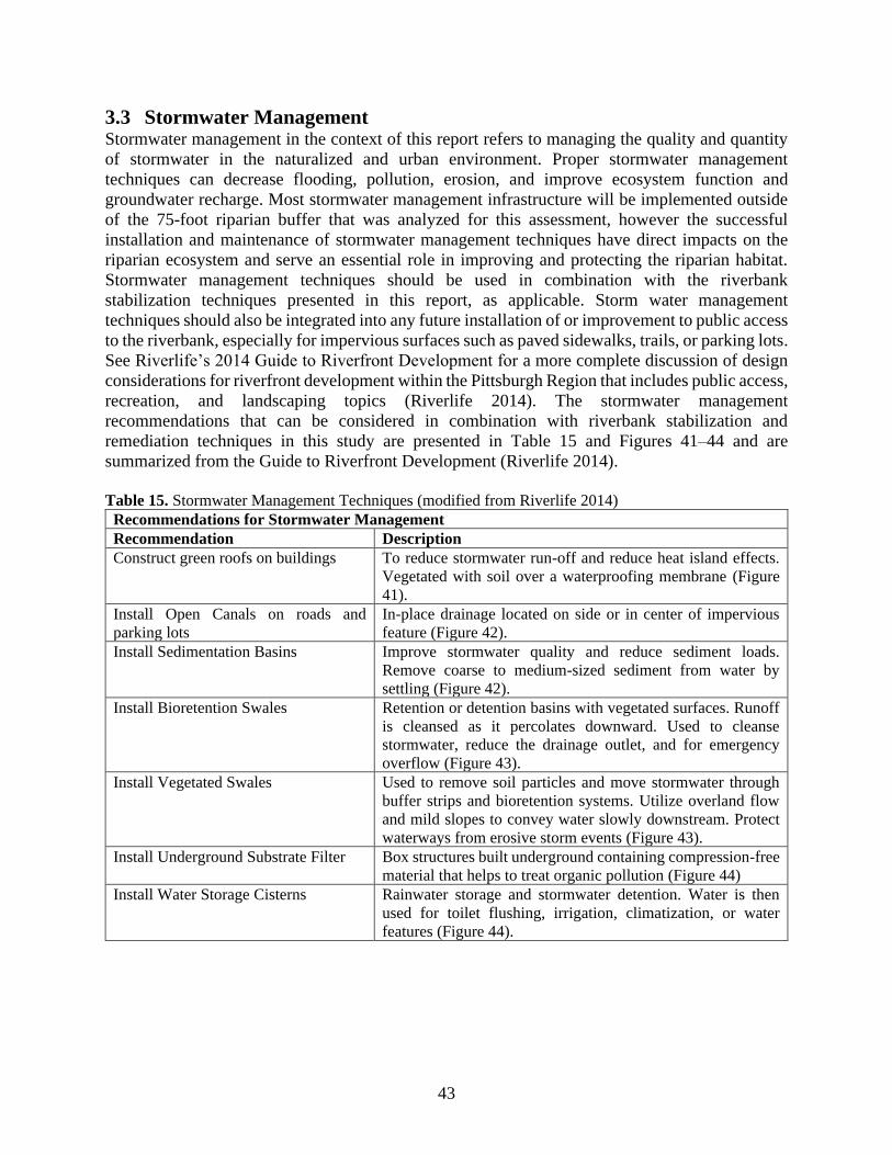
43
3.3 Stormwater Management Stormwater management in the context of this report refers to managing the quality and quantity
of stormwater in the naturalized and urban environment. Proper stormwater management
techniques can decrease flooding, pollution, erosion, and improve ecosystem function and
groundwater recharge. Most stormwater management infrastructure will be implemented outside
of the 75-foot riparian buffer that was analyzed for this assessment, however the successful
installation and maintenance of stormwater management techniques have direct impacts on the
riparian ecosystem and serve an essential role in improving and protecting the riparian habitat.
Stormwater management techniques should be used in combination with the riverbank
stabilization techniques presented in this report, as applicable. Storm water management
techniques should also be integrated into any future installation of or improvement to public access
to the riverbank, especially for impervious surfaces such as paved sidewalks, trails, or parking lots.
See Riverlife’s 2014 Guide to Riverfront Development for a more complete discussion of design
considerations for riverfront development within the Pittsburgh Region that includes public access,
recreation, and landscaping topics (Riverlife 2014). The stormwater management
recommendations that can be considered in combination with riverbank stabilization and
remediation techniques in this study are presented in Table 15 and Figures 41–44 and are
summarized from the Guide to Riverfront Development (Riverlife 2014).
Table 15. Stormwater Management Techniques (modified from Riverlife 2014)
Recommendations for Stormwater Management
Recommendation Description
Construct green roofs on buildings To reduce stormwater run-off and reduce heat island effects.
Vegetated with soil over a waterproofing membrane (Figure
41).
Install Open Canals on roads and
parking lots
In-place drainage located on side or in center of impervious
feature (Figure 42).
Install Sedimentation Basins Improve stormwater quality and reduce sediment loads.
Remove coarse to medium-sized sediment from water by
settling (Figure 42).
Install Bioretention Swales Retention or detention basins with vegetated surfaces. Runoff
is cleansed as it percolates downward. Used to cleanse
stormwater, reduce the drainage outlet, and for emergency
overflow (Figure 43).
Install Vegetated Swales Used to remove soil particles and move stormwater through
buffer strips and bioretention systems. Utilize overland flow
and mild slopes to convey water slowly downstream. Protect
waterways from erosive storm events (Figure 43).
Install Underground Substrate Filter Box structures built underground containing compression-free
material that helps to treat organic pollution (Figure 44)
Install Water Storage Cisterns Rainwater storage and stormwater detention. Water is then
used for toilet flushing, irrigation, climatization, or water
features (Figure 44).
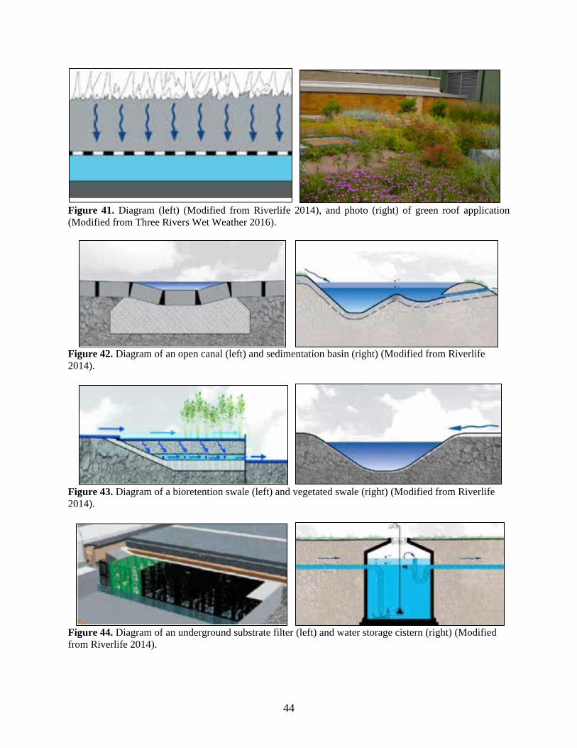
44
Figure 41. Diagram (left) (Modified from Riverlife 2014), and photo (right) of green roof application
(Modified from Three Rivers Wet Weather 2016).
Figure 42. Diagram of an open canal (left) and sedimentation basin (right) (Modified from Riverlife
2014).
Figure 43. Diagram of a bioretention swale (left) and vegetated swale (right) (Modified from Riverlife
2014).
Figure 44. Diagram of an underground substrate filter (left) and water storage cistern (right) (Modified
from Riverlife 2014).
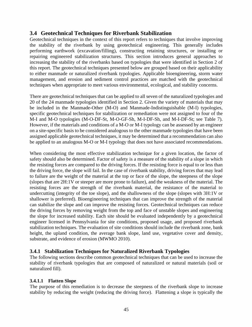
45
3.4 Geotechnical Techniques for Riverbank Stabilization Geotechnical techniques in the context of this report refers to techniques that involve improving
the stability of the riverbank by using geotechnical engineering. This generally includes
performing earthwork (excavation/filling), constructing retaining structures, or installing or
repairing engineered stabilization structures. This section introduces general approaches to
increasing the stability of the riverbanks based on typologies that were identified in Section 2 of
this report. The geotechnical techniques presented below are grouped based on their applicability
to either manmade or naturalized riverbank typologies. Applicable bioengineering, storm water
management, and erosion and sediment control practices are matched with the geotechnical
techniques when appropriate to meet various environmental, ecological, and stability concerns.
There are geotechnical techniques that can be applied to all seven of the naturalized typologies and
20 of the 24 manmade typologies identified in Section 2. Given the variety of materials that may
be included in the Manmade-Other (M-O) and Manmade-Indistinguishable (M-I) typologies,
specific geotechnical techniques for stabilization or remediation were not assigned to four of the
M-I and M-O typologies (M-O-DF-St, M-O-GF-Sh, M-I-DF-Sh, and M-I-DF-St; see Table 7).
However, if the materials and conditions of a M-O or M-I typology can be assessed by an engineer
on a site-specific basis to be considered analogous to the other manmade typologies that have been
assigned applicable geotechnical techniques, it may be determined that a recommendation can also
be applied to an analogous M-O or M-I typology that does not have associated recommendations.
When considering the most effective stabilization technique for a given location, the factor of
safety should also be determined. Factor of safety is a measure of the stability of a slope in which
the resisting forces are compared to the driving forces. If the resisting force is equal to or less than
the driving force, the slope will fail. In the case of riverbank stability, driving forces that may lead
to failure are the weight of the material at the top or face of the slope, the steepness of the slope
(slopes that are 2H:1V or steeper are more prone to failure), and the weakness of the material. The
resisting forces are the strength of the riverbank material, the resistance of the material to
undercutting (integrity of the toe slope), and the shallowness of the slope (slopes with 3H:1V or
shallower is preferred). Bioengineering techniques that can improve the strength of the material
can stabilize the slope and can improve the resisting forces. Geotechnical techniques can reduce
the driving forces by removing weight from the top and face of unstable slopes and engineering
the slope for increased stability. Each site should be evaluated independently by a geotechnical
engineer licensed in Pennsylvania for site conditions, proposed usage, and proposed riverbank
stabilization techniques. The evaluation of site conditions should include the riverbank zone, bank
height, the upland condition, the average bank slope, land use, vegetative cover and density,
substrate, and evidence of erosion (MWMO 2010).
3.4.1 Stabilization Techniques for Naturalized Riverbank Typologies The following sections describe common geotechnical techniques that can be used to increase the
stability of riverbank typologies that are composed of naturalized or natural materials (soil or
naturalized fill).
3.4.1.1 Flatten Slope
The purpose of this remediation is to decrease the steepness of the riverbank slope to increase
stability by reducing the weight (reducing the driving force). Flattening a slope is typically the
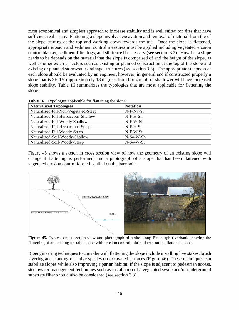
46
most economical and simplest approach to increase stability and is well suited for sites that have
sufficient real estate. Flattening a slope involves excavation and removal of material from the of
the slope starting at the top and working down towards the toe. Once the slope is flattened,
appropriate erosion and sediment control measures must be applied including vegetated erosion
control blanket, sediment filter logs, and silt fence if necessary (see section 3.2). How flat a slope
needs to be depends on the material that the slope is comprised of and the height of the slope, as
well as other external factors such as existing or planned construction at the top of the slope and
existing or planned stormwater drainage structures (see section 3.3). The appropriate steepness of
each slope should be evaluated by an engineer, however, in general and if constructed properly a
slope that is 3H:1V (approximately 18 degrees from horizontal) or shallower will have increased
slope stability. Table 16 summarizes the typologies that are most applicable for flattening the
slope.
Table 16. Typologies applicable for flattening the slope.
Naturalized Typologies Notation Naturalized-Fill-Non-Vegetated-Steep N-F-Nv-St Naturalized-Fill-Herbaceous-Shallow N-F-H-Sh Naturalized-Fill-Woody-Shallow N-F-W-Sh Naturalized-Fill-Herbaceous-Steep N-F-H-St Naturalized-Fill-Woody-Steep N-F-W-St Naturalized-Soil-Woody-Shallow N-So-W-Sh Naturalized-Soil-Woody-Steep N-So-W-St
Figure 45 shows a sketch in cross section view of how the geometry of an existing slope will
change if flattening is performed, and a photograph of a slope that has been flattened with
vegetated erosion control fabric installed on the bare soils.
Figure 45. Typical cross section view and photograph of a site along Pittsburgh riverbank showing the
flattening of an existing unstable slope with erosion control fabric placed on the flattened slope.
Bioengineering techniques to consider with flattening the slope include installing live stakes, brush
layering and planting of native species on excavated surfaces (Figure 46). These techniques can
stabilize slopes while also improving riparian habitat. If the slope is adjacent to pedestrian access,
stormwater management techniques such as installation of a vegetated swale and/or underground
substrate filter should also be considered (see section 3.3).
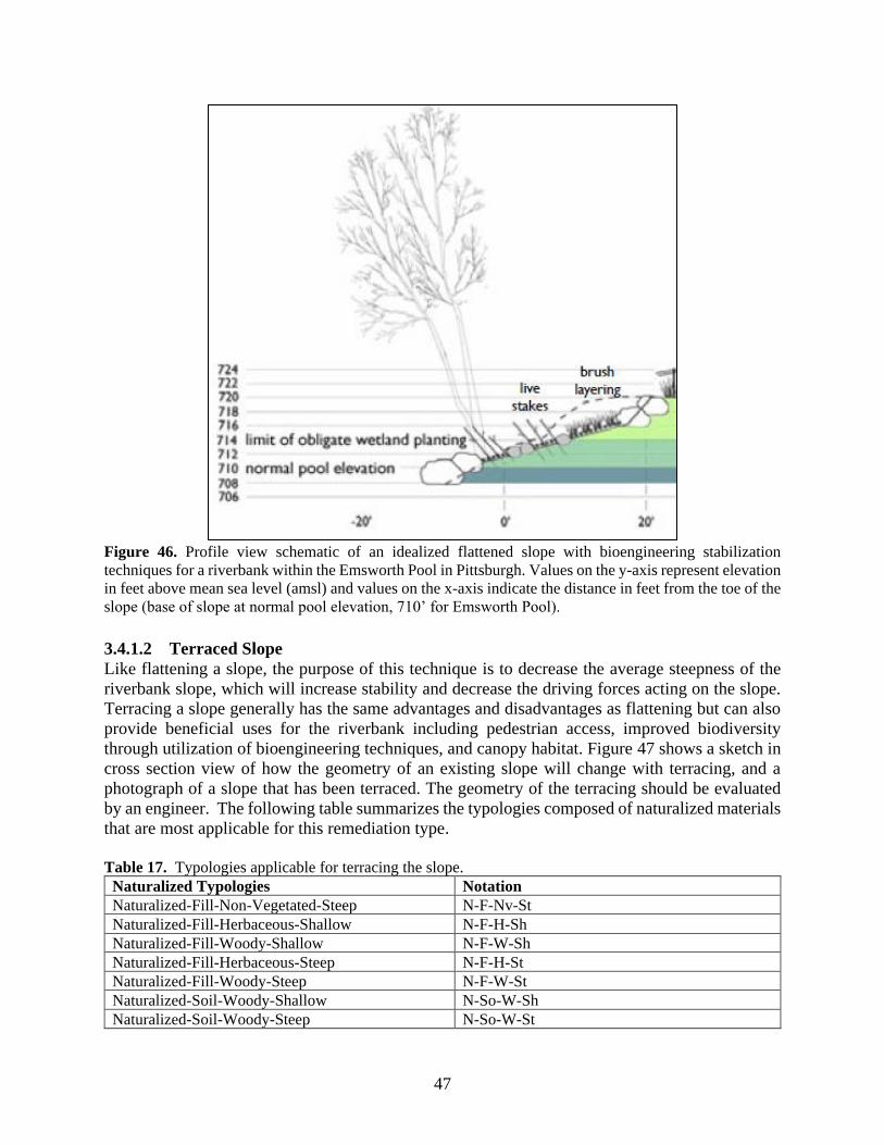
47
Figure 46. Profile view schematic of an idealized flattened slope with bioengineering stabilization
techniques for a riverbank within the Emsworth Pool in Pittsburgh. Values on the y-axis represent elevation
in feet above mean sea level (amsl) and values on the x-axis indicate the distance in feet from the toe of the
slope (base of slope at normal pool elevation, 710’ for Emsworth Pool).
3.4.1.2 Terraced Slope
Like flattening a slope, the purpose of this technique is to decrease the average steepness of the
riverbank slope, which will increase stability and decrease the driving forces acting on the slope.
Terracing a slope generally has the same advantages and disadvantages as flattening but can also
provide beneficial uses for the riverbank including pedestrian access, improved biodiversity
through utilization of bioengineering techniques, and canopy habitat. Figure 47 shows a sketch in
cross section view of how the geometry of an existing slope will change with terracing, and a
photograph of a slope that has been terraced. The geometry of the terracing should be evaluated
by an engineer. The following table summarizes the typologies composed of naturalized materials
that are most applicable for this remediation type.
Table 17. Typologies applicable for terracing the slope.
Naturalized Typologies Notation Naturalized-Fill-Non-Vegetated-Steep N-F-Nv-St Naturalized-Fill-Herbaceous-Shallow N-F-H-Sh Naturalized-Fill-Woody-Shallow N-F-W-Sh Naturalized-Fill-Herbaceous-Steep N-F-H-St Naturalized-Fill-Woody-Steep N-F-W-St Naturalized-Soil-Woody-Shallow N-So-W-Sh Naturalized-Soil-Woody-Steep N-So-W-St
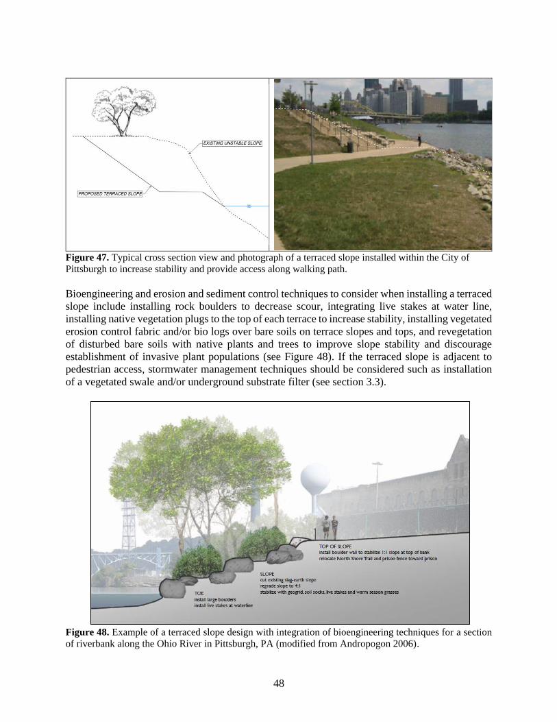
48
Figure 47. Typical cross section view and photograph of a terraced slope installed within the City of
Pittsburgh to increase stability and provide access along walking path.
Bioengineering and erosion and sediment control techniques to consider when installing a terraced
slope include installing rock boulders to decrease scour, integrating live stakes at water line,
installing native vegetation plugs to the top of each terrace to increase stability, installing vegetated
erosion control fabric and/or bio logs over bare soils on terrace slopes and tops, and revegetation
of disturbed bare soils with native plants and trees to improve slope stability and discourage
establishment of invasive plant populations (see Figure 48). If the terraced slope is adjacent to
pedestrian access, stormwater management techniques should be considered such as installation
of a vegetated swale and/or underground substrate filter (see section 3.3).
Figure 48. Example of a terraced slope design with integration of bioengineering techniques for a section
of riverbank along the Ohio River in Pittsburgh, PA (modified from Andropogon 2006).
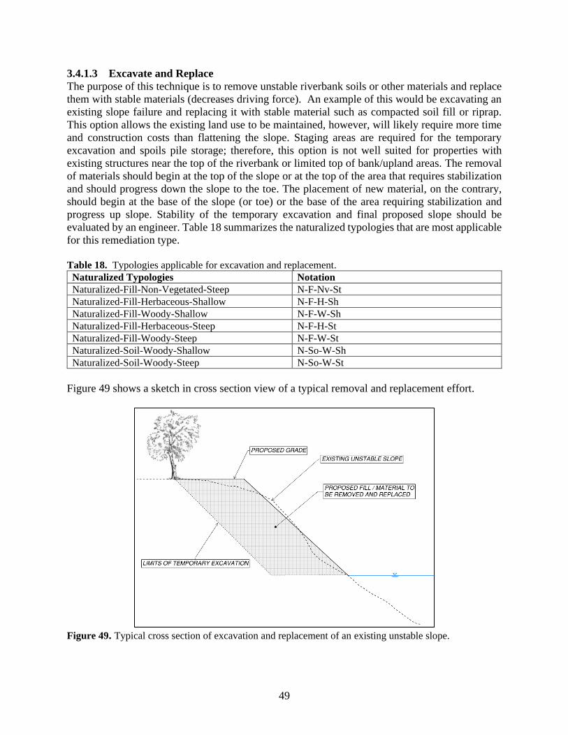
49
3.4.1.3 Excavate and Replace
The purpose of this technique is to remove unstable riverbank soils or other materials and replace
them with stable materials (decreases driving force). An example of this would be excavating an
existing slope failure and replacing it with stable material such as compacted soil fill or riprap.
This option allows the existing land use to be maintained, however, will likely require more time
and construction costs than flattening the slope. Staging areas are required for the temporary
excavation and spoils pile storage; therefore, this option is not well suited for properties with
existing structures near the top of the riverbank or limited top of bank/upland areas. The removal
of materials should begin at the top of the slope or at the top of the area that requires stabilization
and should progress down the slope to the toe. The placement of new material, on the contrary,
should begin at the base of the slope (or toe) or the base of the area requiring stabilization and
progress up slope. Stability of the temporary excavation and final proposed slope should be
evaluated by an engineer. Table 18 summarizes the naturalized typologies that are most applicable
for this remediation type.
Table 18. Typologies applicable for excavation and replacement.
Naturalized Typologies Notation Naturalized-Fill-Non-Vegetated-Steep N-F-Nv-St Naturalized-Fill-Herbaceous-Shallow N-F-H-Sh Naturalized-Fill-Woody-Shallow N-F-W-Sh Naturalized-Fill-Herbaceous-Steep N-F-H-St Naturalized-Fill-Woody-Steep N-F-W-St Naturalized-Soil-Woody-Shallow N-So-W-Sh Naturalized-Soil-Woody-Steep N-So-W-St
Figure 49 shows a sketch in cross section view of a typical removal and replacement effort.
Figure 49. Typical cross section of excavation and replacement of an existing unstable slope.
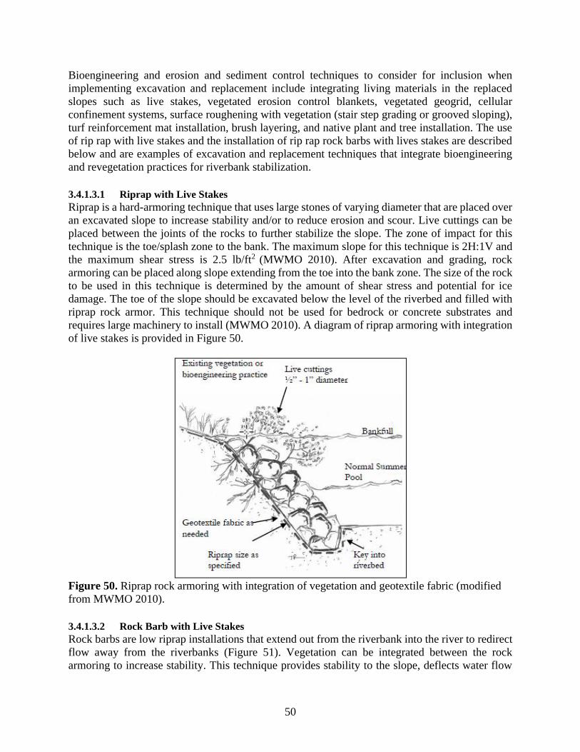
50
Bioengineering and erosion and sediment control techniques to consider for inclusion when
implementing excavation and replacement include integrating living materials in the replaced
slopes such as live stakes, vegetated erosion control blankets, vegetated geogrid, cellular
confinement systems, surface roughening with vegetation (stair step grading or grooved sloping),
turf reinforcement mat installation, brush layering, and native plant and tree installation. The use
of rip rap with live stakes and the installation of rip rap rock barbs with lives stakes are described
below and are examples of excavation and replacement techniques that integrate bioengineering
and revegetation practices for riverbank stabilization.
3.4.1.3.1 Riprap with Live Stakes
Riprap is a hard-armoring technique that uses large stones of varying diameter that are placed over
an excavated slope to increase stability and/or to reduce erosion and scour. Live cuttings can be
placed between the joints of the rocks to further stabilize the slope. The zone of impact for this
technique is the toe/splash zone to the bank. The maximum slope for this technique is 2H:1V and
the maximum shear stress is 2.5 lb/ft2 (MWMO 2010). After excavation and grading, rock
armoring can be placed along slope extending from the toe into the bank zone. The size of the rock
to be used in this technique is determined by the amount of shear stress and potential for ice
damage. The toe of the slope should be excavated below the level of the riverbed and filled with
riprap rock armor. This technique should not be used for bedrock or concrete substrates and
requires large machinery to install (MWMO 2010). A diagram of riprap armoring with integration
of live stakes is provided in Figure 50.
Figure 50. Riprap rock armoring with integration of vegetation and geotextile fabric (modified
from MWMO 2010).
3.4.1.3.2 Rock Barb with Live Stakes
Rock barbs are low riprap installations that extend out from the riverbank into the river to redirect
flow away from the riverbanks (Figure 51). Vegetation can be integrated between the rock
armoring to increase stability. This technique provides stability to the slope, deflects water flow
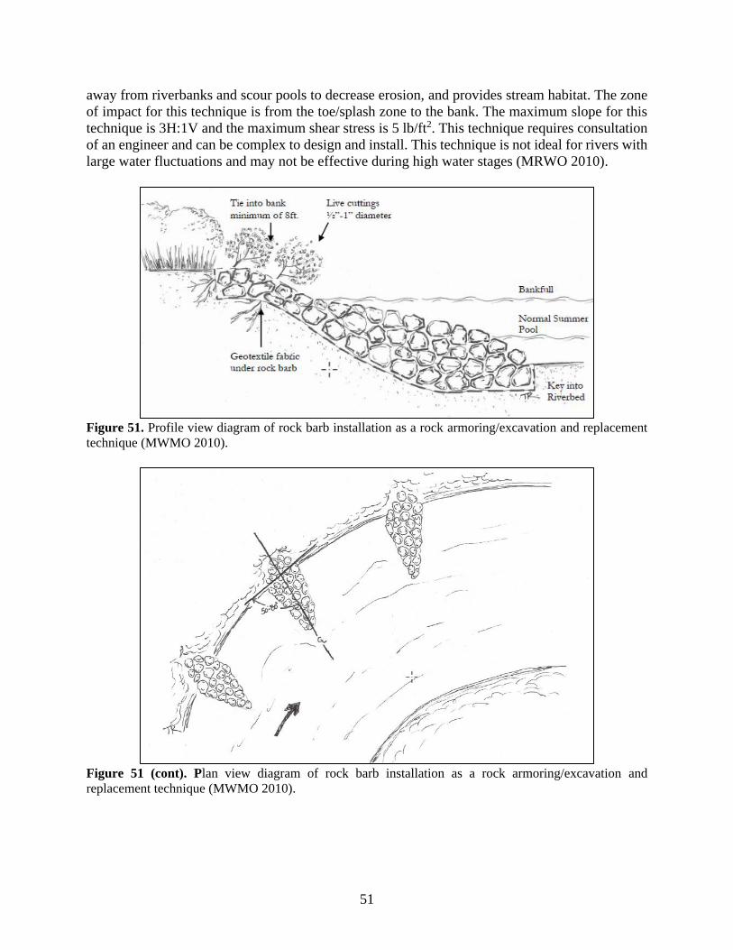
51
away from riverbanks and scour pools to decrease erosion, and provides stream habitat. The zone
of impact for this technique is from the toe/splash zone to the bank. The maximum slope for this
technique is 3H:1V and the maximum shear stress is 5 lb/ft2. This technique requires consultation
of an engineer and can be complex to design and install. This technique is not ideal for rivers with
large water fluctuations and may not be effective during high water stages (MRWO 2010).
Figure 51. Profile view diagram of rock barb installation as a rock armoring/excavation and replacement
technique (MWMO 2010).
Figure 51 (cont). Plan view diagram of rock barb installation as a rock armoring/excavation and
replacement technique (MWMO 2010).
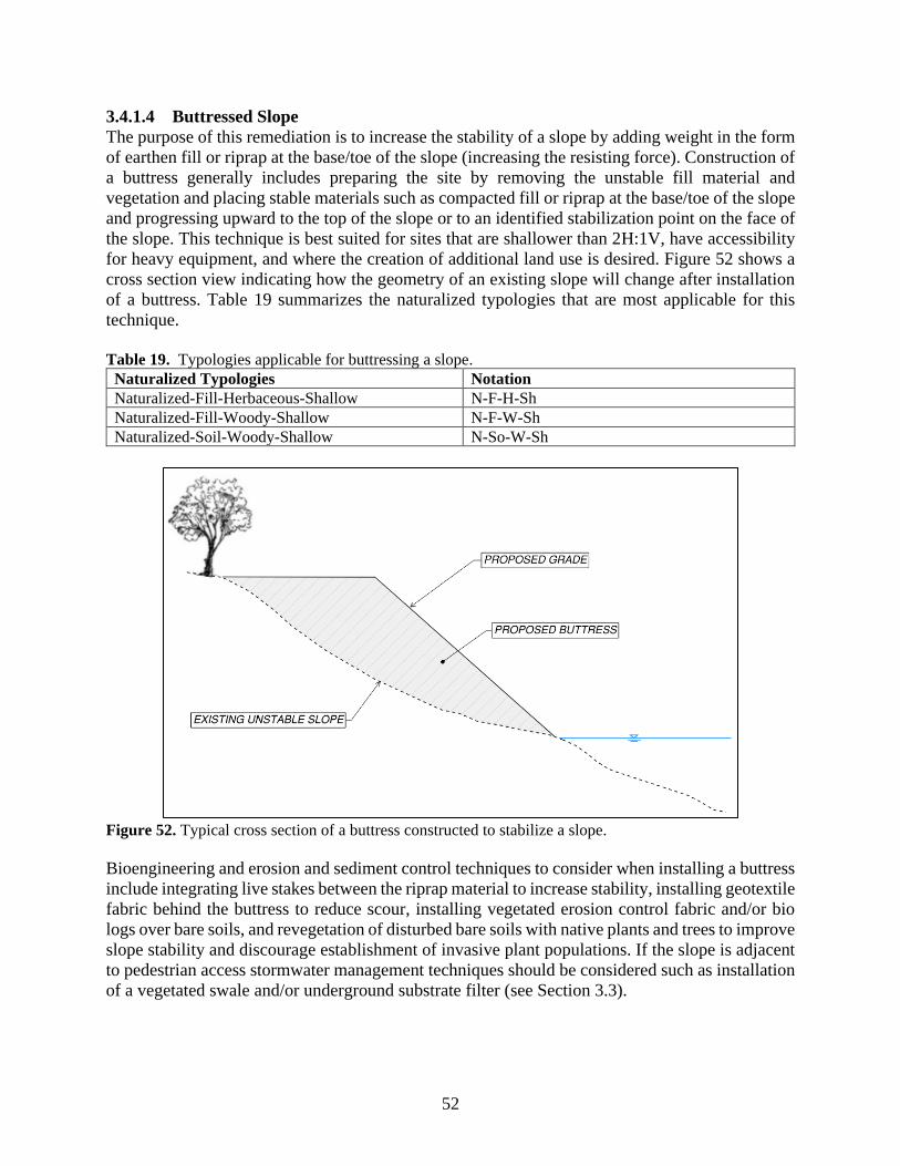
52
3.4.1.4 Buttressed Slope
The purpose of this remediation is to increase the stability of a slope by adding weight in the form
of earthen fill or riprap at the base/toe of the slope (increasing the resisting force). Construction of
a buttress generally includes preparing the site by removing the unstable fill material and
vegetation and placing stable materials such as compacted fill or riprap at the base/toe of the slope
and progressing upward to the top of the slope or to an identified stabilization point on the face of
the slope. This technique is best suited for sites that are shallower than 2H:1V, have accessibility
for heavy equipment, and where the creation of additional land use is desired. Figure 52 shows a
cross section view indicating how the geometry of an existing slope will change after installation
of a buttress. Table 19 summarizes the naturalized typologies that are most applicable for this
technique.
Table 19. Typologies applicable for buttressing a slope.
Naturalized Typologies Notation Naturalized-Fill-Herbaceous-Shallow N-F-H-Sh Naturalized-Fill-Woody-Shallow N-F-W-Sh Naturalized-Soil-Woody-Shallow N-So-W-Sh
Figure 52. Typical cross section of a buttress constructed to stabilize a slope.
Bioengineering and erosion and sediment control techniques to consider when installing a buttress
include integrating live stakes between the riprap material to increase stability, installing geotextile
fabric behind the buttress to reduce scour, installing vegetated erosion control fabric and/or bio
logs over bare soils, and revegetation of disturbed bare soils with native plants and trees to improve
slope stability and discourage establishment of invasive plant populations. If the slope is adjacent
to pedestrian access stormwater management techniques should be considered such as installation
of a vegetated swale and/or underground substrate filter (see Section 3.3).
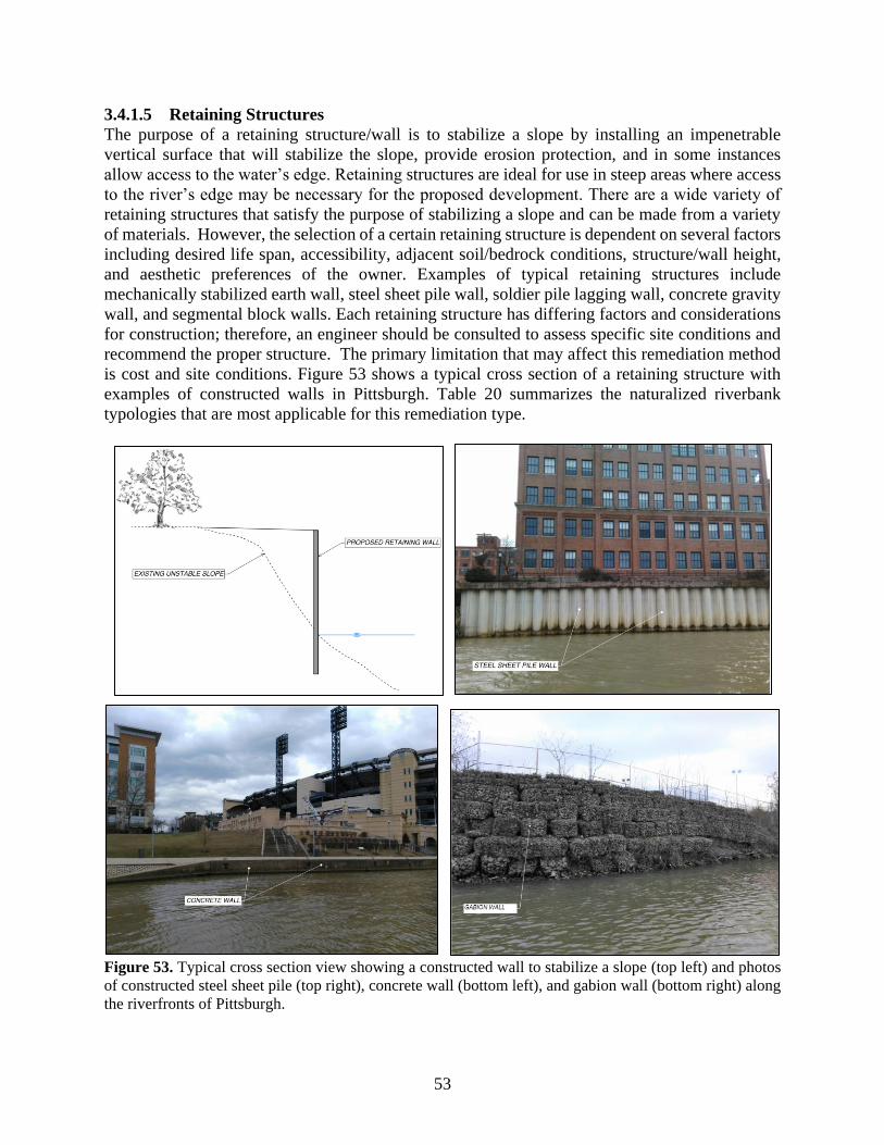
53
3.4.1.5 Retaining Structures
The purpose of a retaining structure/wall is to stabilize a slope by installing an impenetrable
vertical surface that will stabilize the slope, provide erosion protection, and in some instances
allow access to the water’s edge. Retaining structures are ideal for use in steep areas where access
to the river’s edge may be necessary for the proposed development. There are a wide variety of
retaining structures that satisfy the purpose of stabilizing a slope and can be made from a variety
of materials. However, the selection of a certain retaining structure is dependent on several factors
including desired life span, accessibility, adjacent soil/bedrock conditions, structure/wall height,
and aesthetic preferences of the owner. Examples of typical retaining structures include
mechanically stabilized earth wall, steel sheet pile wall, soldier pile lagging wall, concrete gravity
wall, and segmental block walls. Each retaining structure has differing factors and considerations
for construction; therefore, an engineer should be consulted to assess specific site conditions and
recommend the proper structure. The primary limitation that may affect this remediation method
is cost and site conditions. Figure 53 shows a typical cross section of a retaining structure with
examples of constructed walls in Pittsburgh. Table 20 summarizes the naturalized riverbank
typologies that are most applicable for this remediation type.
Figure 53. Typical cross section view showing a constructed wall to stabilize a slope (top left) and photos
of constructed steel sheet pile (top right), concrete wall (bottom left), and gabion wall (bottom right) along
the riverfronts of Pittsburgh.
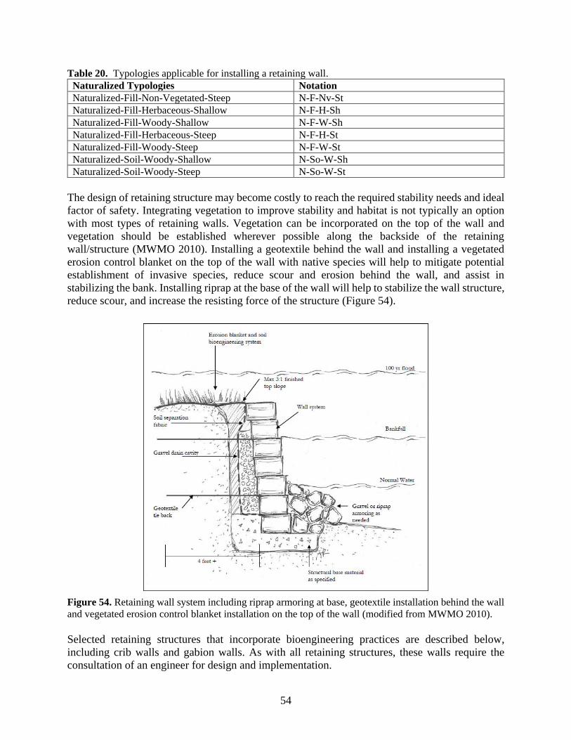
54
Table 20. Typologies applicable for installing a retaining wall.
Naturalized Typologies Notation Naturalized-Fill-Non-Vegetated-Steep N-F-Nv-St Naturalized-Fill-Herbaceous-Shallow N-F-H-Sh Naturalized-Fill-Woody-Shallow N-F-W-Sh Naturalized-Fill-Herbaceous-Steep N-F-H-St Naturalized-Fill-Woody-Steep N-F-W-St Naturalized-Soil-Woody-Shallow N-So-W-Sh Naturalized-Soil-Woody-Steep N-So-W-St
The design of retaining structure may become costly to reach the required stability needs and ideal
factor of safety. Integrating vegetation to improve stability and habitat is not typically an option
with most types of retaining walls. Vegetation can be incorporated on the top of the wall and
vegetation should be established wherever possible along the backside of the retaining
wall/structure (MWMO 2010). Installing a geotextile behind the wall and installing a vegetated
erosion control blanket on the top of the wall with native species will help to mitigate potential
establishment of invasive species, reduce scour and erosion behind the wall, and assist in
stabilizing the bank. Installing riprap at the base of the wall will help to stabilize the wall structure,
reduce scour, and increase the resisting force of the structure (Figure 54).
Figure 54. Retaining wall system including riprap armoring at base, geotextile installation behind the wall
and vegetated erosion control blanket installation on the top of the wall (modified from MWMO 2010).
Selected retaining structures that incorporate bioengineering practices are described below,
including crib walls and gabion walls. As with all retaining structures, these walls require the
consultation of an engineer for design and implementation.
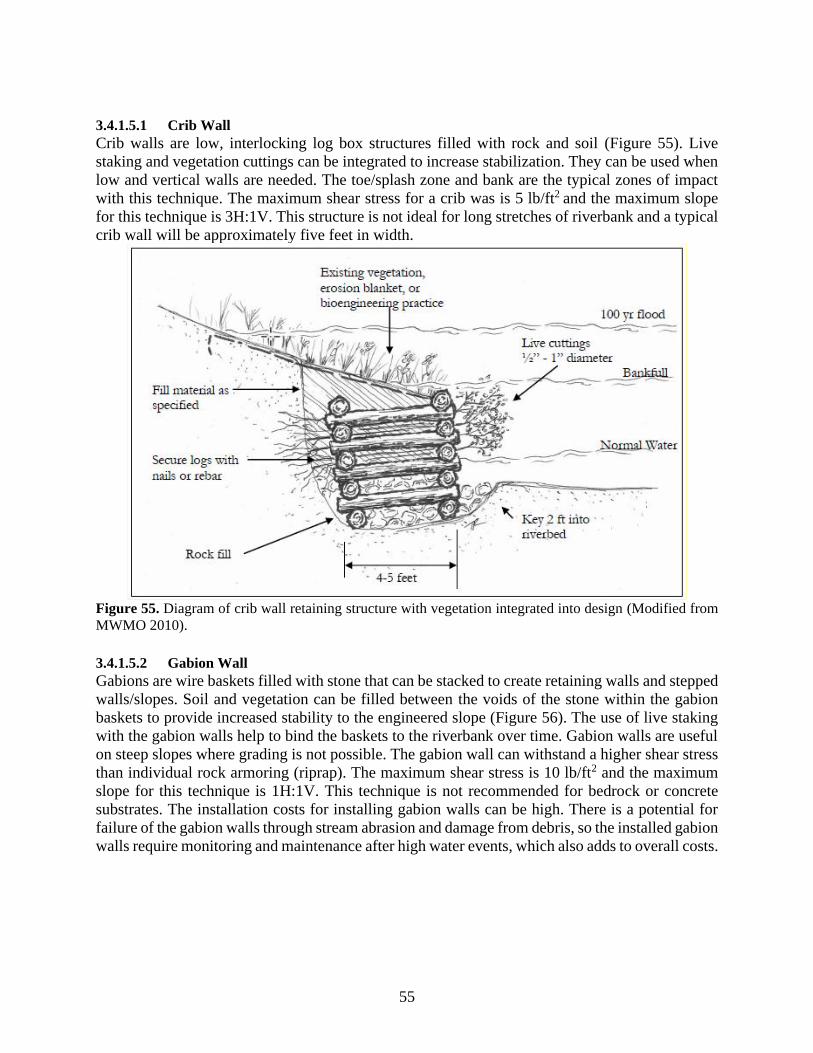
55
3.4.1.5.1 Crib Wall
Crib walls are low, interlocking log box structures filled with rock and soil (Figure 55). Live
staking and vegetation cuttings can be integrated to increase stabilization. They can be used when
low and vertical walls are needed. The toe/splash zone and bank are the typical zones of impact
with this technique. The maximum shear stress for a crib was is 5 lb/ft2 and the maximum slope
for this technique is 3H:1V. This structure is not ideal for long stretches of riverbank and a typical
crib wall will be approximately five feet in width.
Figure 55. Diagram of crib wall retaining structure with vegetation integrated into design (Modified from
MWMO 2010).
3.4.1.5.2 Gabion Wall
Gabions are wire baskets filled with stone that can be stacked to create retaining walls and stepped
walls/slopes. Soil and vegetation can be filled between the voids of the stone within the gabion
baskets to provide increased stability to the engineered slope (Figure 56). The use of live staking
with the gabion walls help to bind the baskets to the riverbank over time. Gabion walls are useful
on steep slopes where grading is not possible. The gabion wall can withstand a higher shear stress
than individual rock armoring (riprap). The maximum shear stress is 10 lb/ft2 and the maximum
slope for this technique is 1H:1V. This technique is not recommended for bedrock or concrete
substrates. The installation costs for installing gabion walls can be high. There is a potential for
failure of the gabion walls through stream abrasion and damage from debris, so the installed gabion
walls require monitoring and maintenance after high water events, which also adds to overall costs.
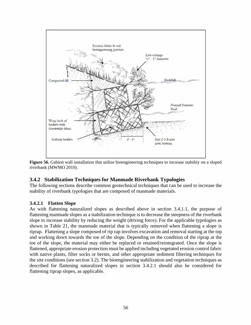
56
Figure 56. Gabion wall installation that utilize bioengineering techniques to increase stability on a sloped
riverbank (MWMO 2010).
3.4.2 Stabilization Techniques for Manmade Riverbank Typologies The following sections describe common geotechnical techniques that can be used to increase the
stability of riverbank typologies that are composed of manmade materials.
3.4.2.1 Flatten Slope
As with flattening naturalized slopes as described above in section 3.4.1.1, the purpose of
flattening manmade slopes as a stabilization technique is to decrease the steepness of the riverbank
slope to increase stability by reducing the weight (driving force). For the applicable typologies as
shown in Table 21, the manmade material that is typically removed when flattening a slope is
riprap. Flattening a slope composed of rip rap involves excavation and removal starting at the top
and working down towards the toe of the slope. Depending on the condition of the riprap at the
toe of the slope, the material may either be replaced or retained/reintegrated. Once the slope is
flattened, appropriate erosion protection must be applied including vegetated erosion control fabric
with native plants, filter socks or berms, and other appropriate sediment filtering techniques for
the site conditions (see section 3.2). The bioengineering stabilization and vegetation techniques as
described for flattening naturalized slopes in section 3.4.2.1 should also be considered for
flattening riprap slopes, as applicable.
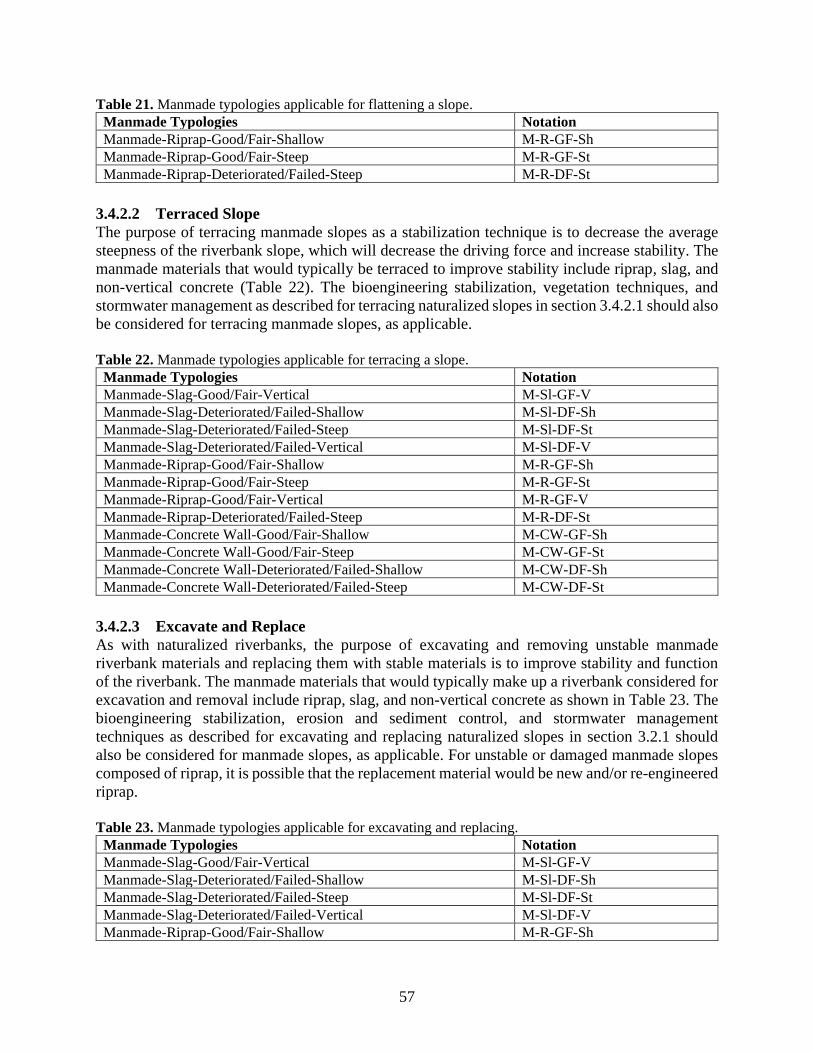
57
Table 21. Manmade typologies applicable for flattening a slope.
Manmade Typologies Notation Manmade-Riprap-Good/Fair-Shallow M-R-GF-Sh Manmade-Riprap-Good/Fair-Steep M-R-GF-St Manmade-Riprap-Deteriorated/Failed-Steep M-R-DF-St
3.4.2.2 Terraced Slope
The purpose of terracing manmade slopes as a stabilization technique is to decrease the average
steepness of the riverbank slope, which will decrease the driving force and increase stability. The
manmade materials that would typically be terraced to improve stability include riprap, slag, and
non-vertical concrete (Table 22). The bioengineering stabilization, vegetation techniques, and
stormwater management as described for terracing naturalized slopes in section 3.4.2.1 should also
be considered for terracing manmade slopes, as applicable.
Table 22. Manmade typologies applicable for terracing a slope.
Manmade Typologies Notation Manmade-Slag-Good/Fair-Vertical M-Sl-GF-V Manmade-Slag-Deteriorated/Failed-Shallow M-Sl-DF-Sh Manmade-Slag-Deteriorated/Failed-Steep M-Sl-DF-St Manmade-Slag-Deteriorated/Failed-Vertical M-Sl-DF-V Manmade-Riprap-Good/Fair-Shallow M-R-GF-Sh Manmade-Riprap-Good/Fair-Steep M-R-GF-St Manmade-Riprap-Good/Fair-Vertical M-R-GF-V Manmade-Riprap-Deteriorated/Failed-Steep M-R-DF-St Manmade-Concrete Wall-Good/Fair-Shallow M-CW-GF-Sh
Manmade-Concrete Wall-Good/Fair-Steep M-CW-GF-St
Manmade-Concrete Wall-Deteriorated/Failed-Shallow M-CW-DF-Sh
Manmade-Concrete Wall-Deteriorated/Failed-Steep M-CW-DF-St
3.4.2.3 Excavate and Replace
As with naturalized riverbanks, the purpose of excavating and removing unstable manmade
riverbank materials and replacing them with stable materials is to improve stability and function
of the riverbank. The manmade materials that would typically make up a riverbank considered for
excavation and removal include riprap, slag, and non-vertical concrete as shown in Table 23. The
bioengineering stabilization, erosion and sediment control, and stormwater management
techniques as described for excavating and replacing naturalized slopes in section 3.2.1 should
also be considered for manmade slopes, as applicable. For unstable or damaged manmade slopes
composed of riprap, it is possible that the replacement material would be new and/or re-engineered
riprap.
Table 23. Manmade typologies applicable for excavating and replacing.
Manmade Typologies Notation Manmade-Slag-Good/Fair-Vertical M-Sl-GF-V Manmade-Slag-Deteriorated/Failed-Shallow M-Sl-DF-Sh Manmade-Slag-Deteriorated/Failed-Steep M-Sl-DF-St Manmade-Slag-Deteriorated/Failed-Vertical M-Sl-DF-V Manmade-Riprap-Good/Fair-Shallow M-R-GF-Sh
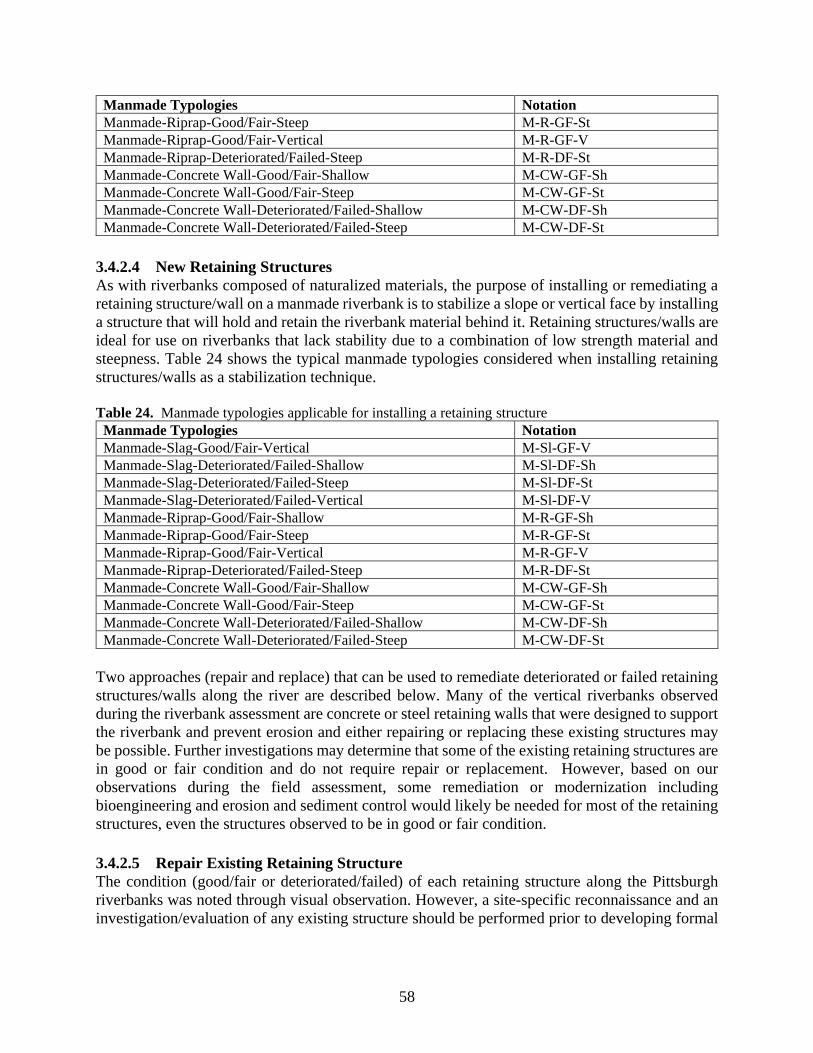
58
Manmade Typologies Notation Manmade-Riprap-Good/Fair-Steep M-R-GF-St Manmade-Riprap-Good/Fair-Vertical M-R-GF-V Manmade-Riprap-Deteriorated/Failed-Steep M-R-DF-St Manmade-Concrete Wall-Good/Fair-Shallow M-CW-GF-Sh Manmade-Concrete Wall-Good/Fair-Steep M-CW-GF-St Manmade-Concrete Wall-Deteriorated/Failed-Shallow M-CW-DF-Sh Manmade-Concrete Wall-Deteriorated/Failed-Steep M-CW-DF-St
3.4.2.4 New Retaining Structures
As with riverbanks composed of naturalized materials, the purpose of installing or remediating a
retaining structure/wall on a manmade riverbank is to stabilize a slope or vertical face by installing
a structure that will hold and retain the riverbank material behind it. Retaining structures/walls are
ideal for use on riverbanks that lack stability due to a combination of low strength material and
steepness. Table 24 shows the typical manmade typologies considered when installing retaining
structures/walls as a stabilization technique.
Table 24. Manmade typologies applicable for installing a retaining structure
Manmade Typologies Notation Manmade-Slag-Good/Fair-Vertical M-Sl-GF-V Manmade-Slag-Deteriorated/Failed-Shallow M-Sl-DF-Sh Manmade-Slag-Deteriorated/Failed-Steep M-Sl-DF-St Manmade-Slag-Deteriorated/Failed-Vertical M-Sl-DF-V Manmade-Riprap-Good/Fair-Shallow M-R-GF-Sh Manmade-Riprap-Good/Fair-Steep M-R-GF-St Manmade-Riprap-Good/Fair-Vertical M-R-GF-V Manmade-Riprap-Deteriorated/Failed-Steep M-R-DF-St Manmade-Concrete Wall-Good/Fair-Shallow M-CW-GF-Sh Manmade-Concrete Wall-Good/Fair-Steep M-CW-GF-St Manmade-Concrete Wall-Deteriorated/Failed-Shallow M-CW-DF-Sh Manmade-Concrete Wall-Deteriorated/Failed-Steep M-CW-DF-St
Two approaches (repair and replace) that can be used to remediate deteriorated or failed retaining
structures/walls along the river are described below. Many of the vertical riverbanks observed
during the riverbank assessment are concrete or steel retaining walls that were designed to support
the riverbank and prevent erosion and either repairing or replacing these existing structures may
be possible. Further investigations may determine that some of the existing retaining structures are
in good or fair condition and do not require repair or replacement. However, based on our
observations during the field assessment, some remediation or modernization including
bioengineering and erosion and sediment control would likely be needed for most of the retaining
structures, even the structures observed to be in good or fair condition.
3.4.2.5 Repair Existing Retaining Structure
The condition (good/fair or deteriorated/failed) of each retaining structure along the Pittsburgh
riverbanks was noted through visual observation. However, a site-specific reconnaissance and an
investigation/evaluation of any existing structure should be performed prior to developing formal
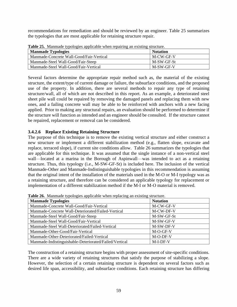
59
recommendations for remediation and should be reviewed by an engineer. Table 25 summarizes
the typologies that are most applicable for retaining structure repair.
Table 25. Manmade typologies applicable when repairing an existing structure.
Manmade Typologies Notation Manmade-Concrete Wall-Good/Fair-Vertical M-CW-GF-V Manmade-Steel Wall-Good/Fair-Steep M-SW-GF-St Manmade-Steel Wall-Good/Fair-Vertical M-SW-GF-V
Several factors determine the appropriate repair method such as, the material of the existing
structure, the extent/type of current damage or failure, the subsurface conditions, and the proposed
use of the property. In addition, there are several methods to repair any type of retaining
structure/wall, all of which are not described in this report. As an example, a deteriorated steel
sheet pile wall could be repaired by removing the damaged panels and replacing them with new
ones, and a failing concrete wall may be able to be reinforced with anchors with a new facing
applied. Prior to making any structural repairs, an evaluation should be performed to determine if
the structure will function as intended and an engineer should be consulted. If the structure cannot
be repaired, replacement or removal can be considered.
3.4.2.6 Replace Existing Retaining Structure
The purpose of this technique is to remove the existing vertical structure and either construct a
new structure or implement a different stabilization method (e.g., flatten slope, excavate and
replace, terraced slope), if current site conditions allow. Table 26 summarizes the typologies that
are applicable for this technique. It was assumed that the single instance of a non-vertical steel
wall—located at a marina in the Borough of Aspinwall—was intended to act as a retaining
structure. Thus, this typology (i.e., M-SW-GF-St) is included here. The inclusion of the vertical
Manmade-Other and Manmade-Indistinguishable typologies in this recommendation is assuming
that the original intent of the installation of the materials used in the M-O or M-I typology was as
a retaining structure, and therefore can be considered an applicable typology for replacement or
implementation of a different stabilization method if the M-I or M-O material is removed.
Table 26. Manmade typologies applicable when replacing an existing structure.
Manmade Typologies Notation Manmade-Concrete Wall-Good/Fair-Vertical M-CW-GF-V Manmade-Concrete Wall-Deteriorated/Failed-Vertical M-CW-DF-V Manmade-Steel Wall-Good/Fair-Steep M-SW-GF-St Manmade-Steel Wall-Good/Fair-Vertical M-SW-GF-V Manmade-Steel Wall-Deteriorated/Failed-Vertical M-SW-DF-V Manmade-Other-Good/Fair-Vertical M-O-GF-V Manmade-Other-Deteriorated/Failed-Vertical M-O-DF-V Manmade-Indistinguishable-Deteriorated/Failed/Vertical M-I-DF-V
The construction of a retaining structure begins with proper assessment of site-specific conditions.
There are a wide variety of retaining structures that satisfy the purpose of stabilizing a slope.
However, the selection of a certain retaining structure is dependent on several factors such as
desired life span, accessibility, and subsurface conditions. Each retaining structure has differing
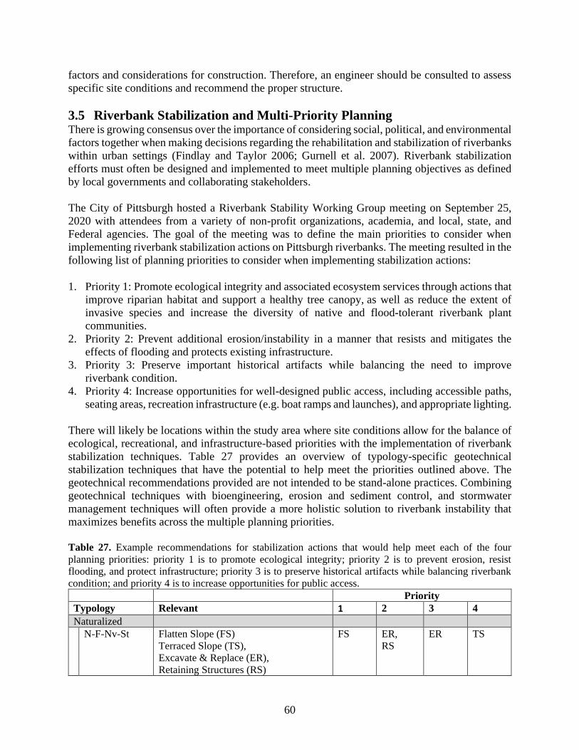
60
factors and considerations for construction. Therefore, an engineer should be consulted to assess
specific site conditions and recommend the proper structure.
3.5 Riverbank Stabilization and Multi-Priority Planning There is growing consensus over the importance of considering social, political, and environmental
factors together when making decisions regarding the rehabilitation and stabilization of riverbanks
within urban settings (Findlay and Taylor 2006; Gurnell et al. 2007). Riverbank stabilization
efforts must often be designed and implemented to meet multiple planning objectives as defined
by local governments and collaborating stakeholders.
The City of Pittsburgh hosted a Riverbank Stability Working Group meeting on September 25,
2020 with attendees from a variety of non-profit organizations, academia, and local, state, and
Federal agencies. The goal of the meeting was to define the main priorities to consider when
implementing riverbank stabilization actions on Pittsburgh riverbanks. The meeting resulted in the
following list of planning priorities to consider when implementing stabilization actions:
1. Priority 1: Promote ecological integrity and associated ecosystem services through actions that
improve riparian habitat and support a healthy tree canopy, as well as reduce the extent of
invasive species and increase the diversity of native and flood-tolerant riverbank plant
communities.
2. Priority 2: Prevent additional erosion/instability in a manner that resists and mitigates the
effects of flooding and protects existing infrastructure.
3. Priority 3: Preserve important historical artifacts while balancing the need to improve
riverbank condition.
4. Priority 4: Increase opportunities for well-designed public access, including accessible paths,
seating areas, recreation infrastructure (e.g. boat ramps and launches), and appropriate lighting.
There will likely be locations within the study area where site conditions allow for the balance of
ecological, recreational, and infrastructure-based priorities with the implementation of riverbank
stabilization techniques. Table 27 provides an overview of typology-specific geotechnical
stabilization techniques that have the potential to help meet the priorities outlined above. The
geotechnical recommendations provided are not intended to be stand-alone practices. Combining
geotechnical techniques with bioengineering, erosion and sediment control, and stormwater
management techniques will often provide a more holistic solution to riverbank instability that
maximizes benefits across the multiple planning priorities.
Table 27. Example recommendations for stabilization actions that would help meet each of the four
planning priorities: priority 1 is to promote ecological integrity; priority 2 is to prevent erosion, resist
flooding, and protect infrastructure; priority 3 is to preserve historical artifacts while balancing riverbank
condition; and priority 4 is to increase opportunities for public access.
Priority
Typology Relevant 1 2 3 4
Naturalized
N-F-Nv-St Flatten Slope (FS)
Terraced Slope (TS),
Excavate & Replace (ER),
Retaining Structures (RS)
FS ER,
RS
ER TS
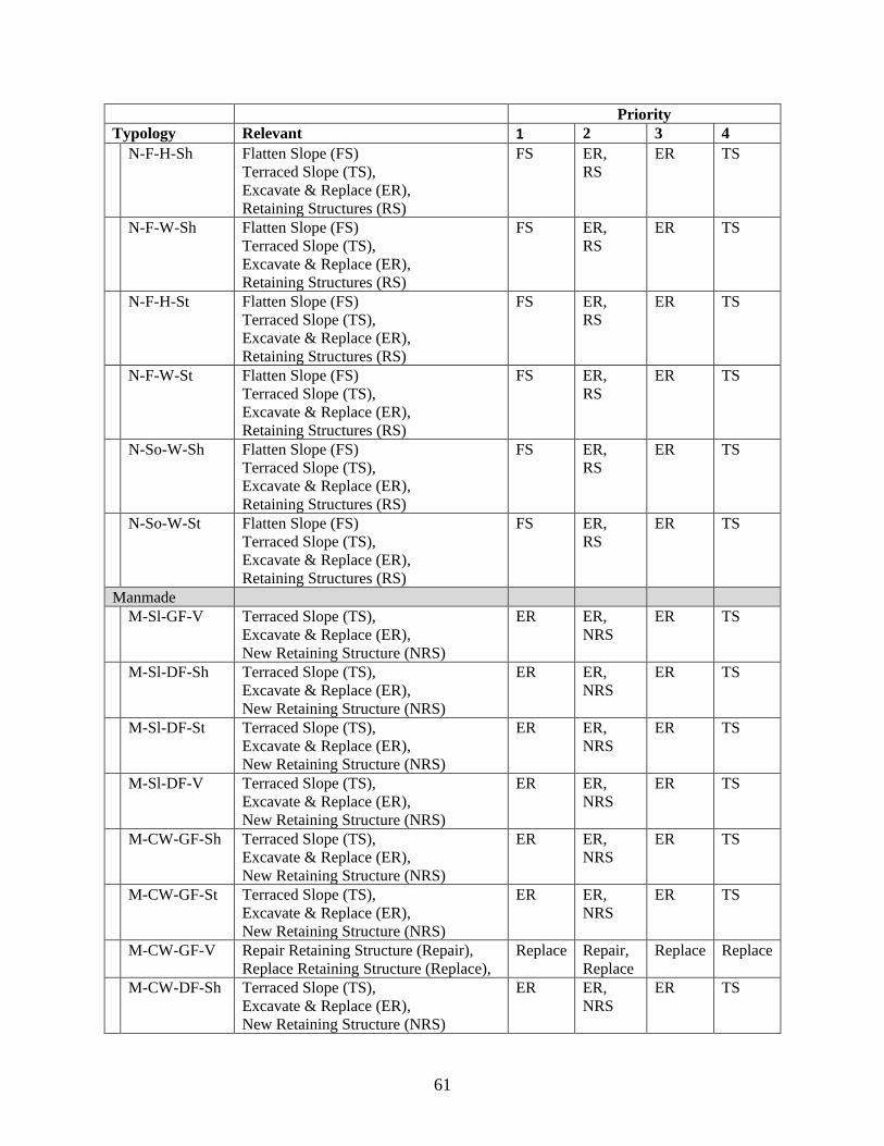
61
Priority
Typology Relevant 1 2 3 4
N-F-H-Sh Flatten Slope (FS)
Terraced Slope (TS),
Excavate & Replace (ER),
Retaining Structures (RS)
FS ER,
RS
ER TS
N-F-W-Sh Flatten Slope (FS)
Terraced Slope (TS),
Excavate & Replace (ER),
Retaining Structures (RS)
FS ER,
RS
ER TS
N-F-H-St Flatten Slope (FS)
Terraced Slope (TS),
Excavate & Replace (ER),
Retaining Structures (RS)
FS ER,
RS
ER TS
N-F-W-St Flatten Slope (FS)
Terraced Slope (TS),
Excavate & Replace (ER),
Retaining Structures (RS)
FS ER,
RS
ER TS
N-So-W-Sh Flatten Slope (FS)
Terraced Slope (TS),
Excavate & Replace (ER),
Retaining Structures (RS)
FS ER,
RS
ER TS
N-So-W-St Flatten Slope (FS)
Terraced Slope (TS),
Excavate & Replace (ER),
Retaining Structures (RS)
FS ER,
RS
ER TS
Manmade
M-Sl-GF-V Terraced Slope (TS),
Excavate & Replace (ER),
New Retaining Structure (NRS)
ER ER,
NRS
ER TS
M-Sl-DF-Sh Terraced Slope (TS),
Excavate & Replace (ER),
New Retaining Structure (NRS)
ER ER,
NRS
ER TS
M-Sl-DF-St Terraced Slope (TS),
Excavate & Replace (ER),
New Retaining Structure (NRS)
ER ER,
NRS
ER TS
M-Sl-DF-V Terraced Slope (TS),
Excavate & Replace (ER),
New Retaining Structure (NRS)
ER ER,
NRS
ER TS
M-CW-GF-Sh Terraced Slope (TS),
Excavate & Replace (ER),
New Retaining Structure (NRS)
ER ER,
NRS
ER TS
M-CW-GF-St Terraced Slope (TS),
Excavate & Replace (ER),
New Retaining Structure (NRS)
ER ER,
NRS
ER TS
M-CW-GF-V Repair Retaining Structure (Repair),
Replace Retaining Structure (Replace),
Replace Repair,
Replace
Replace Replace
M-CW-DF-Sh Terraced Slope (TS),
Excavate & Replace (ER),
New Retaining Structure (NRS)
ER ER,
NRS
ER TS
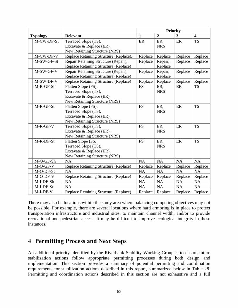
62
Priority
Typology Relevant 1 2 3 4
M-CW-DF-St Terraced Slope (TS),
Excavate & Replace (ER),
New Retaining Structure (NRS)
ER ER,
NRS
ER TS
M-CW-DF-V Replace Retaining Structure (Replace), Replace Replace Replace Replace
M-SW-GF-St Repair Retaining Structure (Repair),
Replace Retaining Structure (Replace)
Replace Repair,
Replace
Replace Replace
M-SW-GF-V Repair Retaining Structure (Repair),
Replace Retaining Structure (Replace)
Replace Repair,
Replace
Replace Replace
M-SW-DF-V Replace Retaining Structure (Replace) Replace Replace Replace Replace
M-R-GF-Sh Flatten Slope (FS),
Terraced Slope (TS),
Excavate & Replace (ER),
New Retaining Structure (NRS)
FS ER,
NRS
ER TS
M-R-GF-St Flatten Slope (FS),
Terraced Slope (TS),
Excavate & Replace (ER),
New Retaining Structure (NRS)
FS ER,
NRS
ER TS
M-R-GF-V Terraced Slope (TS),
Excavate & Replace (ER),
New Retaining Structure (NRS)
FS ER,
NRS
ER TS
M-R-DF-St Flatten Slope (FS,
Terraced Slope (TS),
Excavate & Replace (ER),
New Retaining Structure (NRS)
FS ER,
NRS
ER TS
M-O-GF-Sh NA NA NA NA NA
M-O-GF-V Replace Retaining Structure (Replace) Replace Replace Replace Replace
M-O-DF-St NA NA NA NA NA
M-O-DF-V Replace Retaining Structure (Replace) Replace Replace Replace Replace
M-I-DF-Sh NA NA NA NA NA
M-I-DF-St NA NA NA NA NA
M-I-DF-V Replace Retaining Structure (Replace) Replace Replace Replace Replace
There may also be locations within the study area where balancing competing objectives may not
be possible. For example, there are several locations where hard armoring is in place to protect
transportation infrastructure and industrial sites, to maintain channel width, and/or to provide
recreational and pedestrian access. It may be difficult to improve ecological integrity in these
instances.
4 Permitting Process and Next Steps
An additional priority identified by the Riverbank Stability Working Group is to ensure future
stabilization actions follow appropriate permitting processes during both design and
implementation. This section provides a summary of potential permitting and coordination
requirements for stabilization actions described in this report, summarized below in Table 28.
Permitting and coordination actions described in this section are not exhaustive and a full
63
permitting and coordination review should be conducted before, during, and after project
development to ensure compliance with federal, state, and local laws, ordinances, and
requirements. It is recommended that agencies be contacted early in the planning process to ensure
project feasibility.
4.1 Federal Permitting The U.S Fish and Wildlife Service (USFWS) may require coordination, and depending on the size
and location of the project, USFWS may require the submittal of an environmental review using
the Information for Planning and Consultation (IPaC) tool in addition to the Pennsylvania Natural
Diversity Inventory (PNDI) environmental review tool (described below PA permitting).
Depending on the location and size of the project, the U.S. Environmental Protection Agency
(USEPA) may be involved in the permitting process along with the USACE Pittsburgh District
Regulatory Branch. Projects that may affect areas below the ordinary high-water mark and/or
projects that may include or affect wetlands may require a Clean Water Act 404 Permit/401
Certification. Section 404(e) of the Clean Water Act (CWA) (33 United States Code [U.S.C.]
Section [§] 1344) allows for the issuance of general permits on a statewide basis, which operate in
conjunction with a State regulatory program (Pennsylvania Department of Environmental
Protection; PADEP) that protects the aquatic environment in a manner equivalent to the
Department of the Army regulatory program (USACE), provided that the activities permitted
under each category of such general permits are similar in nature and result in no more than
minimal individual or cumulative adverse effects on the aquatic environment. This Pennsylvania
State Programmatic General Permit # 5 (PASPGP-5) is issued pursuant to Section 404(e) and is
based on and consistent with the requirements of the CWA 404(b)(1) Guidelines (USACE 2011).
The PASPGP-5 permit is not eligible for use on the Ohio River, the Monongahela River, and the
portion of the Allegheny River from its mouth upstream to the Kinzua Dam. Projects ineligible for
authorization under PASPGP-5 may require authorization under the PADEP joint permit process,
which combines applications for a Pennsylvania water obstruction and encroachment permit and
a USACE Section 404 permit. The USACE Pittsburgh District is also a regulatory agency, and has
jurisdiction over Section 10 permits for docks that may or may not protrude into the navigable
waterway and should also be contacted for coordination pertaining to USACE owned and operated
infrastructure that may be involved in the project development .
4.2 State of Pennsylvania Permitting The Pennsylvania Department of Environmental Protection (PADEP) should be contacted early in
the planning process to determine which permitting and regulatory processes must be completed.
Depending on the total size of the project area and proximity to water bodies, the PADEP may
require an Erosion and Sediment Control plan. The PADEP Erosion and Sediment Control Manual
(PADEP 2016) should be reviewed prior the project development. The Chapter 102 permitting
requirements and the National Pollutant Discharge Elimination System (NPDES) permitting
requirements may also apply to the project. PADEP Chapter 106 permitting requirements which
regulates the floodway and floodplain may also apply to the project along with the PADEP joint
permitting process. The Pennsylvania Department of Conservation of Natural Resources
(PADCNR) may require the submittal of a PNDI through the Pennsylvania Natural Heritage
Program (PNHP). The PNDI tool is a required component when applying for any PADEP permit
and is also the mechanism to initiate an environmental review of all state and federally listed
threatened and endangered species. See the program website for more information on this program.
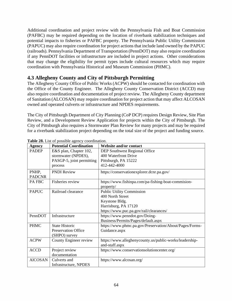
64
Additional coordination and project review with the Pennsylvania Fish and Boat Commission
(PAFBC) may be required depending on the location of riverbank stabilization techniques and
potential impacts to fisheries or PAFBC property. The Pennsylvania Public Utility Commission
(PAPUC) may also require coordination for project actions that include land owned by the PAPUC
(railroads). Pennsylvania Department of Transportation (PennDOT) may also require coordination
if any PennDOT facilities or infrastructure are included in project actions. Other considerations
that may change the eligibility for permit types include cultural resources which may require
coordination with Pennsylvania Historical and Museum Commission (PHMC).
4.3 Allegheny County and City of Pittsburgh Permitting The Allegheny County Office of Public Works (ACPW) should be contacted for coordination with
the Office of the County Engineer. The Allegheny County Conservation District (ACCD) may
also require coordination and documentation of project review. The Allegheny County department
of Sanitation (ALCOSAN) may require coordination for project action that may affect ALCOSAN
owned and operated culverts or infrastructure and NPDES requirements.
The City of Pittsburgh Department of City Planning (CoP DCP) requires Design Review, Site Plan
Review, and a Development Review Application for projects within the City of Pittsburgh. The
City of Pittsburgh also requires a Stormwater Plan Review for many projects and may be required
for a riverbank stabilization project depending on the total size of the project and funding source.
Table 28. List of possible agency coordination.
Agency Potential Coordination Website and/or contact
PADEP E&S plan, Chapter 102,
stormwater (NPDES),
PASGP-5, joint permitting
process
DEP Southwest Regional Office
400 Waterfront Drive
Pittsburgh, PA 15222
412-442-4000
PNHP,
PADCNR
PNDI Review https://conservationexplorer.dcnr.pa.gov/
PA FBC Fisheries review https://www.fishinpa.com/pa-fishing-boat-commision-
property/
PAPUC Railroad clearance Public Utility Commission
400 North Street
Keystone Bldg.
Harrisburg, PA 17120
https://www.puc.pa.gov/rail/clearances/
PennDOT Infrastructure https://www.penndot.gov/Doing-
Business/Permits/Pages/default.aspx
PHMC State Historic
Preservation Office
(SHPO) survey
https://www.phmc.pa.gov/Preservation/About/Pages/Forms-
Guidance.aspx
ACPW County Engineer review https://www.alleghenycounty.us/public-works/leadership-
and-staff.aspx
ACCD Project review
documentation
https://www.conservationsolutioncenter.org/
AlCOSAN Culverts and
Infrastructure, NPDES
https://www.alcosan.org/
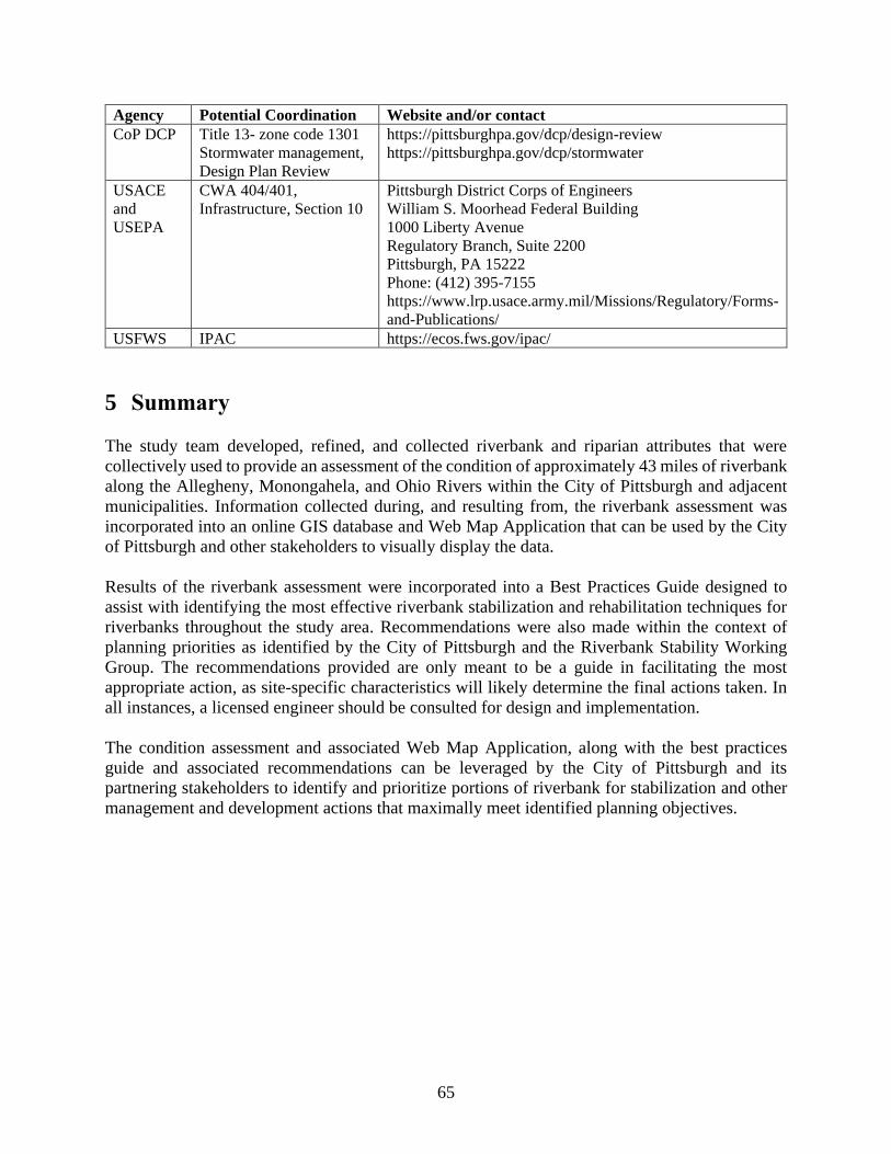
65
Agency Potential Coordination Website and/or contact
CoP DCP Title 13- zone code 1301
Stormwater management,
Design Plan Review
https://pittsburghpa.gov/dcp/design-review
https://pittsburghpa.gov/dcp/stormwater
USACE
and
USEPA
CWA 404/401,
Infrastructure, Section 10
Pittsburgh District Corps of Engineers
William S. Moorhead Federal Building
1000 Liberty Avenue
Regulatory Branch, Suite 2200
Pittsburgh, PA 15222
Phone: (412) 395-7155
https://www.lrp.usace.army.mil/Missions/Regulatory/Forms-
and-Publications/
USFWS IPAC https://ecos.fws.gov/ipac/
5 Summary
The study team developed, refined, and collected riverbank and riparian attributes that were
collectively used to provide an assessment of the condition of approximately 43 miles of riverbank
along the Allegheny, Monongahela, and Ohio Rivers within the City of Pittsburgh and adjacent
municipalities. Information collected during, and resulting from, the riverbank assessment was
incorporated into an online GIS database and Web Map Application that can be used by the City
of Pittsburgh and other stakeholders to visually display the data.
Results of the riverbank assessment were incorporated into a Best Practices Guide designed to
assist with identifying the most effective riverbank stabilization and rehabilitation techniques for
riverbanks throughout the study area. Recommendations were also made within the context of
planning priorities as identified by the City of Pittsburgh and the Riverbank Stability Working
Group. The recommendations provided are only meant to be a guide in facilitating the most
appropriate action, as site-specific characteristics will likely determine the final actions taken. In
all instances, a licensed engineer should be consulted for design and implementation.
The condition assessment and associated Web Map Application, along with the best practices
guide and associated recommendations can be leveraged by the City of Pittsburgh and its
partnering stakeholders to identify and prioritize portions of riverbank for stabilization and other
management and development actions that maximally meet identified planning objectives.
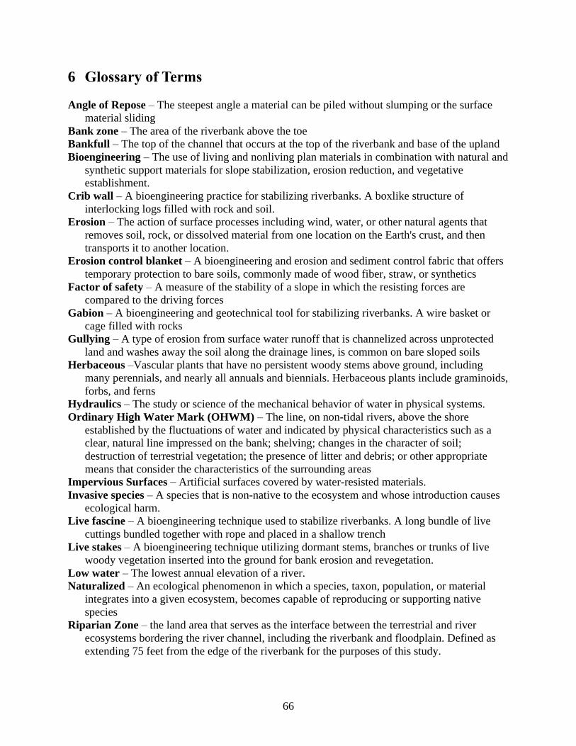
66
6 Glossary of Terms
Angle of Repose – The steepest angle a material can be piled without slumping or the surface
material sliding
Bank zone – The area of the riverbank above the toe
Bankfull – The top of the channel that occurs at the top of the riverbank and base of the upland
Bioengineering – The use of living and nonliving plan materials in combination with natural and
synthetic support materials for slope stabilization, erosion reduction, and vegetative
establishment.
Crib wall – A bioengineering practice for stabilizing riverbanks. A boxlike structure of
interlocking logs filled with rock and soil.
Erosion – The action of surface processes including wind, water, or other natural agents that
removes soil, rock, or dissolved material from one location on the Earth's crust, and then
transports it to another location.
Erosion control blanket – A bioengineering and erosion and sediment control fabric that offers
temporary protection to bare soils, commonly made of wood fiber, straw, or synthetics
Factor of safety – A measure of the stability of a slope in which the resisting forces are
compared to the driving forces
Gabion – A bioengineering and geotechnical tool for stabilizing riverbanks. A wire basket or
cage filled with rocks
Gullying – A type of erosion from surface water runoff that is channelized across unprotected
land and washes away the soil along the drainage lines, is common on bare sloped soils
Herbaceous –Vascular plants that have no persistent woody stems above ground, including
many perennials, and nearly all annuals and biennials. Herbaceous plants include graminoids,
forbs, and ferns
Hydraulics – The study or science of the mechanical behavior of water in physical systems.
Ordinary High Water Mark (OHWM) – The line, on non-tidal rivers, above the shore
established by the fluctuations of water and indicated by physical characteristics such as a
clear, natural line impressed on the bank; shelving; changes in the character of soil;
destruction of terrestrial vegetation; the presence of litter and debris; or other appropriate
means that consider the characteristics of the surrounding areas
Impervious Surfaces – Artificial surfaces covered by water-resisted materials.
Invasive species – A species that is non-native to the ecosystem and whose introduction causes
ecological harm.
Live fascine – A bioengineering technique used to stabilize riverbanks. A long bundle of live
cuttings bundled together with rope and placed in a shallow trench
Live stakes – A bioengineering technique utilizing dormant stems, branches or trunks of live
woody vegetation inserted into the ground for bank erosion and revegetation.
Low water – The lowest annual elevation of a river.
Naturalized – An ecological phenomenon in which a species, taxon, population, or material
integrates into a given ecosystem, becomes capable of reproducing or supporting native
species
Riparian Zone – the land area that serves as the interface between the terrestrial and river
ecosystems bordering the river channel, including the riverbank and floodplain. Defined as
extending 75 feet from the edge of the riverbank for the purposes of this study.
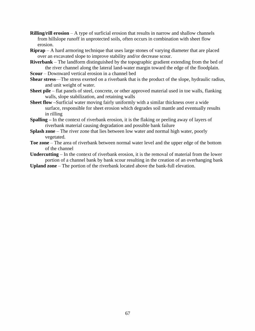
67
Rilling/rill erosion – A type of surficial erosion that results in narrow and shallow channels
from hillslope runoff in unprotected soils, often occurs in combination with sheet flow
erosion.
Riprap – A hard armoring technique that uses large stones of varying diameter that are placed
over an excavated slope to improve stability and/or decrease scour.
Riverbank – The landform distinguished by the topographic gradient extending from the bed of
the river channel along the lateral land-water margin toward the edge of the floodplain.
Scour – Downward vertical erosion in a channel bed
Shear stress—The stress exerted on a riverbank that is the product of the slope, hydraulic radius,
and unit weight of water.
Sheet pile – flat panels of steel, concrete, or other approved material used in toe walls, flanking
walls, slope stabilization, and retaining walls
Sheet flow –Surficial water moving fairly uniformly with a similar thickness over a wide
surface, responsible for sheet erosion which degrades soil mantle and eventually results
in rilling
Spalling – In the context of riverbank erosion, it is the flaking or peeling away of layers of
riverbank material causing degradation and possible bank failure
Splash zone – The river zone that lies between low water and normal high water, poorly
vegetated.
Toe zone – The area of riverbank between normal water level and the upper edge of the bottom
of the channel
Undercutting – In the context of riverbank erosion, it is the removal of material from the lower
portion of a channel bank by bank scour resulting in the creation of an overhanging bank
Upland zone – The portion of the riverbank located above the bank-full elevation.
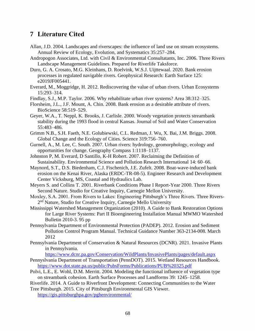
68
7 Literature Cited
Allan, J.D. 2004. Landscapes and riverscapes: the influence of land use on stream ecosystems.
Annual Review of Ecology, Evolution, and Systematics 35:257–284.
Andropogon Associates, Ltd. with Civil & Environmental Consultatants, Inc. 2006. Three Rivers
Landscape Management Guidelines. Prepared for Riverlife Taksforce.
Duro, G. A. Crosato, M.G. Kleinhans, D. Roelvink, W.S.J. Uijttewaal. 2020. Bank erosion
processes in regulated navigable rivers. Geophysical Research: Earth Surface 125:
e2019JF005441.
Everard, M., Moggridge, H. 2012. Rediscovering the value of urban rivers. Urban Ecosystems
15:293–314.
Findlay, S.J., M.P. Taylor. 2006. Why rehabilitate urban river systems? Area 38:312–325.
Florsheim, J.L., J.F. Mount, A. Chin. 2008. Bank erosion as a desirable attribute of rivers.
BioScience 58:519–529.
Geyer, W.A., T. Neppl, K. Brooks, J. Carlisle. 2000. Woody vegetation protects streambank
stability during the 1993 flood in central Kansas. Journal of Soil and Water Conservation
55:483–486.
Grimm N.B., S.H. Faeth, N.E. Golubiewski, C.L. Redman, J. Wu, X. Bai, J.M. Briggs. 2008.
Global Change and the Ecology of Cities. Science 319:756–760.
Gurnell, A., M. Lee, C. South. 2007. Urban rivers: hydrology, geomorphology, ecology and
opportunities for change. Geography Compass 1:1118–1137.
Johnston P, M. Everard, D Santillo, K-H Robert. 2007. Reclaiming the Definition of
Sustainability. Environmental Science and Pollution Research International 14: 60–66.
Maynord, S.T., D.S. Biedenham, C.J. Fischenich, J.E. Zufelt. 2008. Boat-wave-induced bank
erosion on the Kenai River, Alaska (ERDC-TR-08-5). Engineer Research and Development
Center Vicksburg, MS, Coastal and Hydraulics Lab.
Meyers S. and Collins T. 2001. Riverbank Conditions Phase I Report-Year 2000. Three Rivers
Second Nature. Studio for Creative Inquiry, Carnegie Mellon University.
Moxley, S.A. 2001. From Rivers to Lakes: Engineering Pittsburgh’s Three Rivers. Three Rivers-
2nd Nature, Studio for Creative Inquiry, Carnegie Mello University
Mississippi Watershed Management Organization (2010). A Guide to Bank Restoration Options
for Large River Systems: Part II Bioengineering Installation Manual MWMO Watershed
Bulletin 2010-3. 95 pp
Pennsylvania Department of Environmental Protection (PADEP). 2012. Erosion and Sediment
Pollution Control Program Manual. Technical Guidance Number 363-2134-008. March
2012
Pennsylvania Department of Conservation & Natural Resources (DCNR). 2021. Invasive Plants
in Pennsylvania.
https://www.dcnr.pa.gov/Conservation/WildPlants/InvasivePlants/pages/default.aspx
Pennyslvania Department of Transportation (PennDOT). 2015. Wetland Resources Handbook.
https://www.dot.state.pa.us/public/PubsForms/Publications/PUB%20325.pdf
Polvi, L.E., E. Wohl, D.M. Merritt. 2004. Modeling the functional influence of vegetation type
on streambank cohesion. Earth Surface Processes and Landforms 39: 1245–1258.
Riverlife. 2014. A Guide to Riverfront Development: Connecting Communities to the Water
Tree Pittsburgh. 2015. City of Pittsburgh Environmental GIS Viewer.
https://gis.pittsburghpa.gov/pghenvironmental/
69
Three Rivers Wet Weather. 2016. Incorporating Green Infrastructure into Stormwater
Management Ordinances: Green Roofs. Green Roofs | 3 Rivers Wet Weather
U.S. Department of Agriculture, Soil Conservation Service. 1989. Loose riprap protection,
Minnesota Technical Note 3m U.S. Department of Agriculture, Soil Conservation Service,
St. Paul, Minnesota, July 1989.
U.S Department of Agriculture, Natural Resource Conservation Service. 2019. Web Soil
Survey. Web Soil Survey - Home (usda.gov)
U.S. Department of the Interior Bureau of Reclamation. 1963. Hydraulic model studies of the
river outlet works of Oroville dam. Retrieved from
https://www.usbr.gov/tsc/techreferences/hydraulics_lab/pubs/HYD/HYD-299.pdf
U.S Army Corps of Engineers. 2011. Pennsylvania State Programmatic General Permit 4
Microsoft Word - PASPGP-4-Revision-ESA-PNDI-9-25-15.docx (army.mil)
U.S Army Corps of Engineers. 2021. Emsworth Lock and Dams.
https://www.lrp.usace.army.mil/Missions/Navigation/Locks-and-Dams/Emsworth-Locks-
Dams/
Wynn, T., S. Mostaghimi. 2006. The effects of vegetation and soil type on streambank erosion,
southwestern Virginia, USA. Journal of the American Water Resources Association 42:69–
82.


![POSTER Riverbank Proj[1]](https://img.pdfslide.net/doc/110x75/577d263d1a28ab4e1ea0a0e9/poster-riverbank-proj1.jpg)