Embed Size (px)
Citation preview
RIVET HANDBOOK
BLIND RIVETS
RIVET HANDBOOK
PAGE 2
Introduction 5a Rivet Fastening Explanation of “blind” side fastening Concepts Installation Grip Range Break Loads Galvanic Corrosion Removal of Blind Rivets Standards 5b Rivets Material types Sizes and codes Mechanical properties Head types Special types 5c Rivet Tools Hand tools
Pneumatic tools

BLIND RIVETS
RIVET HANDBOOK
PAGE 3
5a Rivet Fastening Concepts Introduction • Although bolting is the most common from of fastening in the world, it is restricted in
usage because of the need to screw a nut on the end. There are many applications where the back of the job cannot be accesses, such as fastening to tubing or walls.
• In these cases, the most common solution is to use Blind Rivets to fasten the job. Blind rivets are termed so because there is no need for access to the rear or ‘blind’ side of the joint.
• The use of rivets in fastening most applications has been proven to be superior and extremely cost effective when compared with other methods of fastening. Welding, sheet metal screws, bolts and nuts and solid rivets all require extensive labour. There are three main reasons why blind rivets are used.
1. Low Installed cost.
Up to 15 rivets per minute can be installed without any specialised labour. The unit cost is also much lower than other types of fastener.
2. Versatility Blind rivets are available in many types, sizes and materials to meet the requirements of the most demanding applications.
3. Reliability Materials are permanently clamped and provided the correct rivet is used can withstand severe vibration and environmental conditions.
• However, blind rivets are limited in their individual strength and should only be used
when fastening relatively light gauge materials.
BLIND RIVETS
RIVET HANDBOOK
PAGE 4
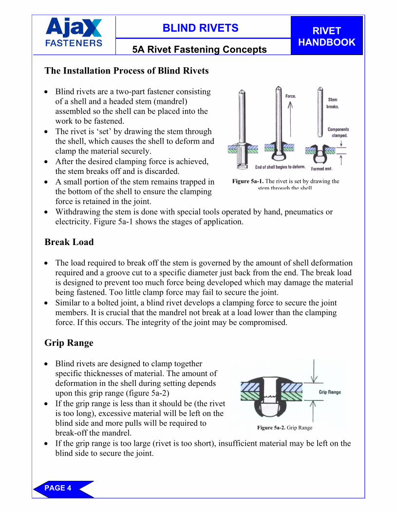
5A Rivet Fastening Concepts The Installation Process of Blind Rivets • Blind rivets are a two-part fastener consisting
of a shell and a headed stem (mandrel) assembled so the shell can be placed into the work to be fastened.
• The rivet is ‘set’ by drawing the stem through the shell, which causes the shell to deform and clamp the material securely.
• After the desired clamping force is achieved, the stem breaks off and is discarded.
• A small portion of the stem remains trapped in the bottom of the shell to ensure the clamping force is retained in the joint.
• Withdrawing the stem is done with special tools operated by hand, pneumatics or electricity. Figure 5a-1 shows the stages of application.
Break Load • The load required to break off the stem is governed by the amount of shell deformation
required and a groove cut to a specific diameter just back from the end. The break load is designed to prevent too much force being developed which may damage the material being fastened. Too little clamp force may fail to secure the joint.
• Similar to a bolted joint, a blind rivet develops a clamping force to secure the joint members. It is crucial that the mandrel not break at a load lower than the clamping force. If this occurs. The integrity of the joint may be compromised.
Grip Range • Blind rivets are designed to clamp together
specific thicknesses of material. The amount of deformation in the shell during setting depends upon this grip range (figure 5a-2)
• If the grip range is less than it should be (the rivet is too long), excessive material will be left on the blind side and more pulls will be required to break-off the mandrel.
• If the grip range is too large (rivet is too short), insufficient material may be left on the blind side to secure the joint.
Figure 5a-1. The rivet is set by drawing the stem through the shell.
Figure 5a-2. Grip Range
BLIND RIVETS
RIVET HANDBOOK
PAGE 5
5a Rivet Fastening Concepts Galvanic Corrosion • When dissimilar metals come into contact in the presence of an electrolyte, a galvanic
action occurs which corrodes one metal at a faster rate and the other more slowly. • The rate of corrosion depends upon a) the difference in electrical potential, b) the
conductivity of the electrolyte and c) the relative sizes of the contacting areas. • Blind rivets are regularly used with dissimilar metals such as aluminium, stainless steel,
mild steel, zinc-coated steel and copper. In applications high in moisture content – such as air conditioners and marine environments – particular care needs to be taken to minimise the effect of galvanic corrosion.
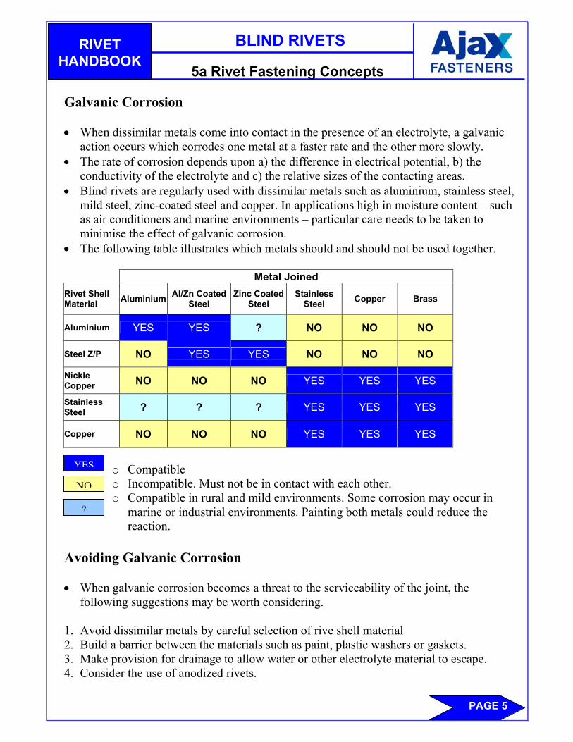
• The following table illustrates which metals should and should not be used together. Metal Joined Rivet Shell Material Aluminium Al/Zn Coated
Steel Zinc Coated
Steel Stainless
Steel Copper Brass
Aluminium YES YES ? NO NO NO
Steel Z/P NO YES YES NO NO NO
Nickle Copper NO NO NO YES YES YES
Stainless Steel ? ? ? YES YES YES
Copper NO NO NO YES YES YES
o Compatible o Incompatible. Must not be in contact with each other. o Compatible in rural and mild environments. Some corrosion may occur in
marine or industrial environments. Painting both metals could reduce the reaction.
Avoiding Galvanic Corrosion • When galvanic corrosion becomes a threat to the serviceability of the joint, the
following suggestions may be worth considering. 1. Avoid dissimilar metals by careful selection of rive shell material 2. Build a barrier between the materials such as paint, plastic washers or gaskets. 3. Make provision for drainage to allow water or other electrolyte material to escape. 4. Consider the use of anodized rivets.
YES
NO
?
BLIND RIVETS
RIVET HANDBOOK
PAGE 6
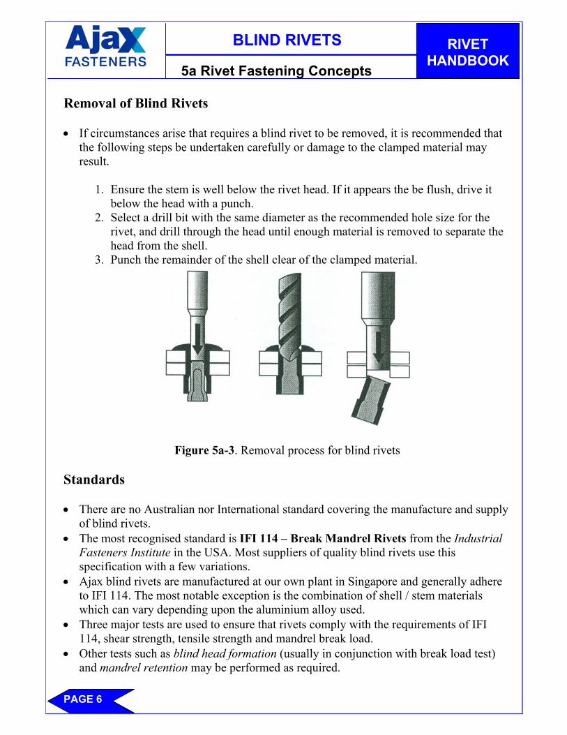
5a Rivet Fastening Concepts Removal of Blind Rivets • If circumstances arise that requires a blind rivet to be removed, it is recommended that
the following steps be undertaken carefully or damage to the clamped material may result.
1. Ensure the stem is well below the rivet head. If it appears the be flush, drive it
below the head with a punch. 2. Select a drill bit with the same diameter as the recommended hole size for the
rivet, and drill through the head until enough material is removed to separate the head from the shell.
3. Punch the remainder of the shell clear of the clamped material.
Figure 5a-3. Removal process for blind rivets Standards • There are no Australian nor International standard covering the manufacture and supply
of blind rivets. • The most recognised standard is IFI 114 – Break Mandrel Rivets from the Industrial
Fasteners Institute in the USA. Most suppliers of quality blind rivets use this specification with a few variations.
• Ajax blind rivets are manufactured at our own plant in Singapore and generally adhere to IFI 114. The most notable exception is the combination of shell / stem materials which can vary depending upon the aluminium alloy used.
• Three major tests are used to ensure that rivets comply with the requirements of IFI 114, shear strength, tensile strength and mandrel break load.
• Other tests such as blind head formation (usually in conjunction with break load test) and mandrel retention may be performed as required.
BLIND RIVETS
RIVET HANDBOOK
PAGE 7
5b Types of Blind Rivets Shell and Stem Materials • Blind rivets owe their popularity to ease of installation and versatility. The thousands of
applications that use rivets created a demand for rivets made from various types of material.
• Usually, the governing factors in material selection are strength, corrosion resistance and the material to be fastened.
• As a general rule, the shell material should be the same as the material under the head, ie, if aluminium is fastened to steel, use steel rivets.
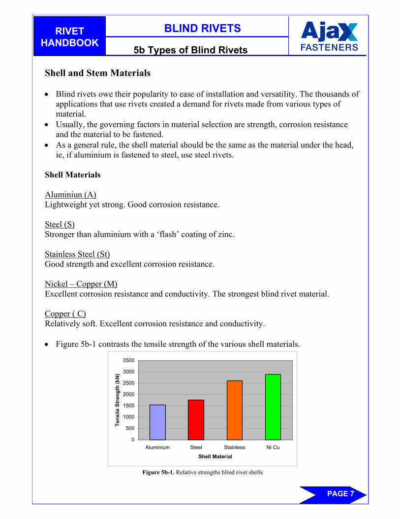
Shell Materials Aluminiun (A) Lightweight yet strong. Good corrosion resistance. Steel (S) Stronger than aluminium with a ‘flash’ coating of zinc. Stainless Steel (St) Good strength and excellent corrosion resistance. Nickel – Copper (M) Excellent corrosion resistance and conductivity. The strongest blind rivet material. Copper ( C) Relatively soft. Excellent corrosion resistance and conductivity. • Figure 5b-1 contrasts the tensile strength of the various shell materials.
0
500
1000
1500
2000
2500
3000
3500
Aluminium Steel Stainless Ni Cu
Shell Material
Tens
ile S
tren
gth
(kN
)
Figure 5b-1. Relative strengths blind rivet shells
BLIND RIVETS
RIVET HANDBOOK
PAGE 8
5b Types of Blind Rivets Stem Materials • Because the greater portion of the stem is discarded after setting, the stem material is
not as crucial, save that it must be ate least the equivalent strength of the shell material. If not, it will be unable to deform the end of the shell.
• Steel is the most common, although stainless and aluminium stems are available in some rivets.
• Part of the stem remains in the shell after setting. In the case of steel, this part may rust, an undesirable attribute in many circumstances. In these cases, stainless and aluminium stems may be specified.
Sizes and Codes • Contrary to popular belief of many ‘expert’ rivet users, a blind rivet will set in one
application of the tool – provided the correct rivet is used for that particular job. To assist with sorting through the many varied types of blind rivets, codes are used to ensure the best part can be used for the specific application.
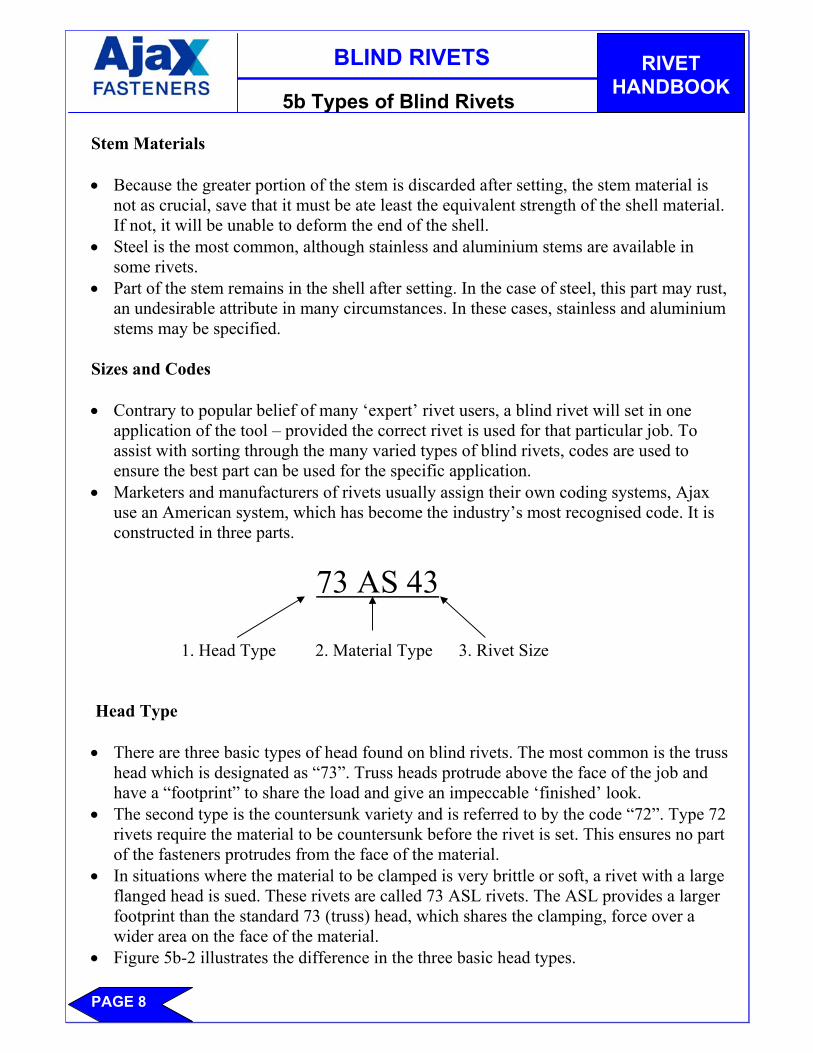
• Marketers and manufacturers of rivets usually assign their own coding systems, Ajax use an American system, which has become the industry’s most recognised code. It is constructed in three parts.
73 AS 43 1. Head Type 2. Material Type 3. Rivet Size
Head Type • There are three basic types of head found on blind rivets. The most common is the truss
head which is designated as “73”. Truss heads protrude above the face of the job and have a “footprint” to share the load and give an impeccable ‘finished’ look.
• The second type is the countersunk variety and is referred to by the code “72”. Type 72 rivets require the material to be countersunk before the rivet is set. This ensures no part of the fasteners protrudes from the face of the material.
• In situations where the material to be clamped is very brittle or soft, a rivet with a large flanged head is sued. These rivets are called 73 ASL rivets. The ASL provides a larger footprint than the standard 73 (truss) head, which shares the clamping, force over a wider area on the face of the material.
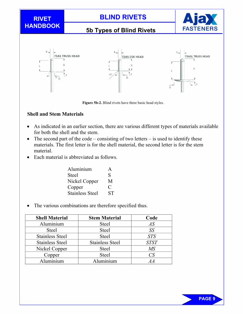
• Figure 5b-2 illustrates the difference in the three basic head types.
BLIND RIVETS
RIVET HANDBOOK
PAGE 9
5b Types of Blind Rivets
Figure 5b-2. Blind rivets have three basic head styles. Shell and Stem Materials • As indicated in an earlier section, there are various different types of materials available
for both the shell and the stem. • The second part of the code – consisting of two letters – is used to identify these
materials. The first letter is for the shell material, the second letter is for the stem material.
• Each material is abbreviated as follows.
Aluminium A Steel S Nickel Copper M Copper C Stainless Steel ST
• The various combinations are therefore specified thus.
Shell Material Stem Material Code Aluminium Steel AS
Steel Steel SS Stainless Steel Steel STS Stainless Steel Stainless Steel STST Nickel Copper Steel MS
Copper Steel CS Aluminium Aluminium AA
BLIND RIVETS
RIVET HANDBOOK
PAGE 10
5b Types of Blind Rivets In the case of special types of rivet, the material code may be combined with another features, eg. 73 ASMG is a truss head Aluminium Steel Multi-Grip. There will be more on special rivets in later sections. Size • The third section of the code designates the size. The coding system can be rather
complicated until clearly understood and even after then it is best to refer to the data sheets.
• Rivets are measured under the old imperial system although it is common for metric specifications to be given. For this reason, conversions are given on the data sheets. The size code – consisting of two or more numbers – is also in two parts. The first part gives the diameter of the shell and the second part gives the thickness of material the rivet is designed to clamp (Grip Range).
The second figure is not the length of the rivet shell
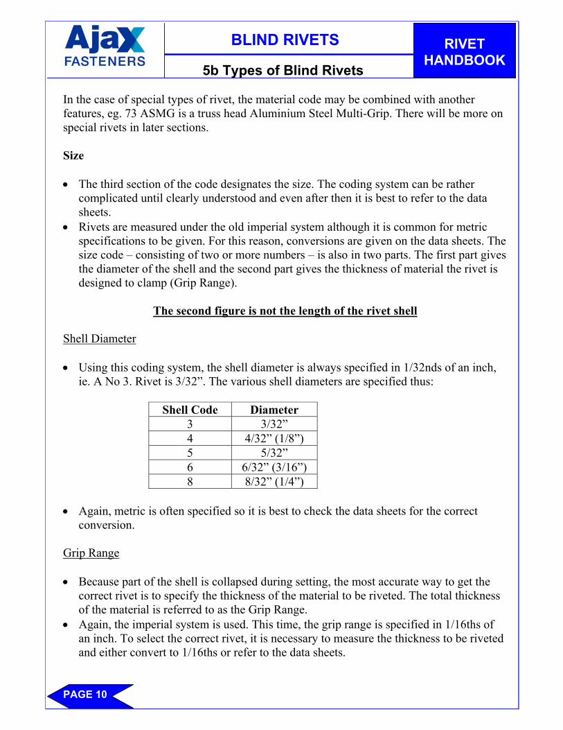
Shell Diameter • Using this coding system, the shell diameter is always specified in 1/32nds of an inch,
ie. A No 3. Rivet is 3/32”. The various shell diameters are specified thus:
Shell Code Diameter 3 3/32” 4 4/32” (1/8”) 5 5/32” 6 6/32” (3/16”) 8 8/32” (1/4”)
• Again, metric is often specified so it is best to check the data sheets for the correct
conversion. Grip Range • Because part of the shell is collapsed during setting, the most accurate way to get the
correct rivet is to specify the thickness of the material to be riveted. The total thickness of the material is referred to as the Grip Range.
• Again, the imperial system is used. This time, the grip range is specified in 1/16ths of an inch. To select the correct rivet, it is necessary to measure the thickness to be riveted and either convert to 1/16ths or refer to the data sheets.
BLIND RIVETS
RIVET HANDBOOK
PAGE 11
5b Types of Blind Rivets Specifying By Code • By now, the rivet code at the beginning of this section should make sense. Let’s have a
look at exactly what it is specifying.
73 AS 43 73 = Truss Head A = Aluminium Shell S = Steel Stem 4 = 4/32” Shell Diameter 3 = 3/16” Grip Range
• Using the correct rivet is vital to secure the joint properly. Whereas the user has a choice of shell diameter and material, the grip range is dictated by the job itself. Failure to use the correct rivet can cause the joint to collapse.
Special Types of Blind Rivet • Since the principle behind blind rivets was conceived, many variations have been
developed to satisfy the growing number of applications taking advantage of the simplicity offered. The following blind rivets are all stocked by Ajax Fasteners or are available from various sources.
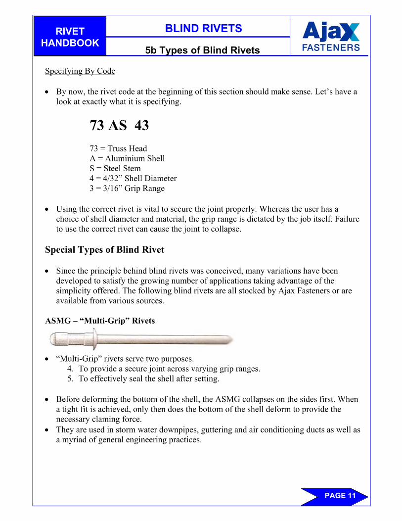
ASMG – “Multi-Grip” Rivets
• “Multi-Grip” rivets serve two purposes.
4. To provide a secure joint across varying grip ranges. 5. To effectively seal the shell after setting.
• Before deforming the bottom of the shell, the ASMG collapses on the sides first. When
a tight fit is achieved, only then does the bottom of the shell deform to provide the necessary claming force.
• They are used in storm water downpipes, guttering and air conditioning ducts as well as a myriad of general engineering practices.
BLIND RIVETS
RIVET HANDBOOK
PAGE 12
5b Types of Blind Rivets ASL – Large Flanged Rivets
• The large head diameter on the ASL is ideal for soft materials. The clamping force is
spread over a wider area, which prevents excessive damage on the face of the job. ASG –Grooved Rivets • Angular grooves around the rivet shell provide excellent holding power when set in less
stiff materials such as wood and plastics. TA – Aluminium Sealed Rivets
• The base of a TA rivet is sealed and therefore waterproof. The mandrel is attached to
the inside of the shell ensuring no gaps for water or air to pass through. Commonly used in water tanks, roofing and aluminium windows.
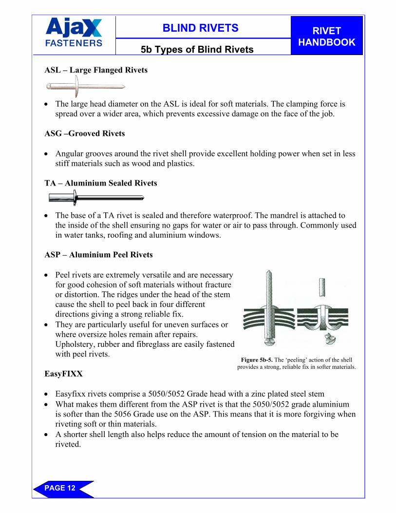
ASP – Aluminium Peel Rivets • Peel rivets are extremely versatile and are necessary
for good cohesion of soft materials without fracture or distortion. The ridges under the head of the stem cause the shell to peel back in four different directions giving a strong reliable fix.
• They are particularly useful for uneven surfaces or where oversize holes remain after repairs. Upholstery, rubber and fibreglass are easily fastened with peel rivets.
EasyFIXX • Easyfixx rivets comprise a 5050/5052 Grade head with a zinc plated steel stem • What makes them different from the ASP rivet is that the 5050/5052 grade aluminium
is softer than the 5056 Grade use on the ASP. This means that it is more forgiving when riveting soft or thin materials.
• A shorter shell length also helps reduce the amount of tension on the material to be riveted.
Figure 5b-5. The ‘peeling’ action of the shell provides a strong, reliable fix in softer materials.
BLIND RIVETS
RIVET HANDBOOK
PAGE 13
5c Rivet Setting Tools Rivet Tools • Selecting the correct rivet setting tool can be as important as selecting the correct rivet.
Using a pneumatic tool to set ten 73 AS 42’s can only be considered overkill, but would be ideal for setting 1,000 per day! The cost savings in labour alone would justify the expense, not to mention the Workcover claims!
• Many different types of tools are available to suit just about any situation imaginable. For reasons listed above, pneumatic tools are the preferred option for production lines and manufacturers. Often, they are used in a fixed work station which allows jobs to be set faster with less effort.
• Hand tools are used by the handyman who sets only a few rivets, and in situations where compressed air is not available for the pneumatic tool.
• Electric tools are also available although their popularity is restricted by a slow setting time.
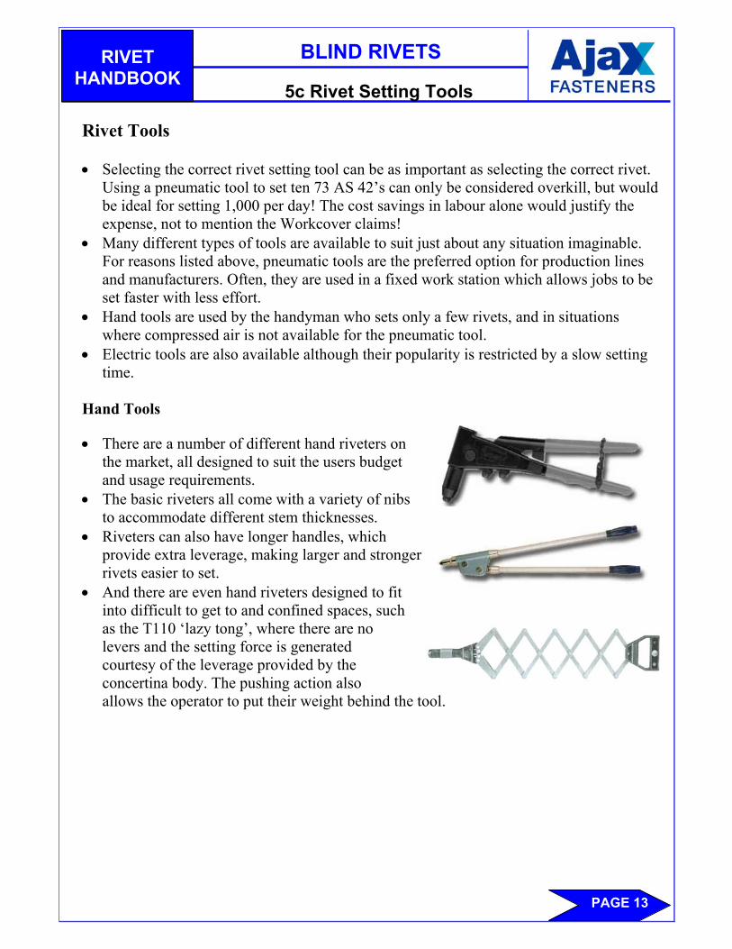
Hand Tools • There are a number of different hand riveters on
the market, all designed to suit the users budget and usage requirements.
• The basic riveters all come with a variety of nibs to accommodate different stem thicknesses.
• Riveters can also have longer handles, which provide extra leverage, making larger and stronger rivets easier to set.
• And there are even hand riveters designed to fit into difficult to get to and confined spaces, such as the T110 ‘lazy tong’, where there are no levers and the setting force is generated courtesy of the leverage provided by the concertina body. The pushing action also allows the operator to put their weight behind the tool.

BLIND RIVETS
RIVET HANDBOOK
PAGE 14
5c Rivet Setting Tools Pneumatic Rivet Tools • Hand tools may be unsuitable for production lines where large quantities of rivets are
set, or when the shell material is relatively hard, such as stainless steel and nickel-copper. For these applications, pneumatic tools are a better option.
• The tools use air pressure to apply a traction force to the rivet stem during setting. This relieves stress on the operator and reduces the chances of fatigue and carpel tunnel syndrome.
• Built-in features such as silencers, mechanical shock reducers and weight distribution mean that the modern air riveters are more comfortable to us, which increases productivity and tool performance.
Operation
1. The rivet stem is placed in the nosepiece in a similar fashion to hand tools.
2. Pressure on the trigger mechanism causes air to withdraw from the jaw case, which firmly grips the stem.
3. After setting, the spent stem remains in the head of the riveter. A gentle tilt backwards slides the stem into a collector at the rear of the tool. Vacuum units are available for some tools, which eliminates the last operation.