Embed Size (px)
Citation preview

R+L HYDRAULICS GESAMTKATALOGR+L HYDRAULICS GENERAL CATALOGUE


3
R+L HYDRAULICS GESAMTKATALOGR+L HYDRAULICS GENERAL CATALOGUE

4
DAS UNTERNEHMEN
THE COMPANY
Mit R+L HYDRAULICS, einem Unternehmen der weltweit operierenden Timken Company, setzen Sie auf einen Spezialisten für Qualitätsprodukte erstklassiger Performance in der Fluid- und Antriebstechnik: zum Beispiel bei Hydraulik-Komponenten der Marke Raja oder Antriebstechnik der Marke Lovejoy.
By choosing R+L HYDRAULICS, a company of the worldwide operating Timken Company, you count on the specialist for quality components of fluid technology and power transmission: e.g. hydraulic components by Raja or power transmission by Lovejoy.

5
DAS UNTERNEHMEN
THE COMPANY
HOHE ANFORDERUNGEN. BESTE LÖSUNGEN.
R+L HYDRAULICS entwickelt und fertigt ein ebenso umfas-sendes, wie auf Ihre Anforderungen maßgeschneidertes Portfolio hochwertiger Komponenten für die Fluid- und An-triebstechnik. Individuelle Lösungen für höchste Ansprüche in Maschinen-, Schiffs- und Fahrzeugbau, in der Stahlindus-trie und Offshore-Technik sowie für spezielle Anwendungen des Anlagenbaus, bilden einen wichtigen Bestandteil Ihres Unternehmenserfolgs.
IHRE VORTEILE• Qualitätskomponenten zu fairen Konditionen• Verbesserung Ihrer Marktposition durch Nutzung unserer
Kompetenzen in Entwicklung, Qualität und Service• Direkte und persönliche Beratung durch unseren Custo-
mer Service• Schnelle Lieferzeiten durch eine optimierte Supply-Chain• Projektbezogene Entwicklung unserer Komponenten auf
Ihre individuellen Anforderungen• Verkürzung Ihrer Reaktionszeiten: Das Auslegungstool
FLUIDWARE® APP kann die Auslegung einer Baugruppe, etwa aus Pumpenträger, Wellenkupplung und Zubehör, umgehend – auf Basis Ihrer individuellen Konditionen - kalkulieren.
HIGH REQUIREMENTS. THE BEST SOLUTIONS.
YOUR ADVANTAGES• Quality components at fair conditions • Improvement of your market position by using our
competences in development, quality and service • Direct and personal consultancy by our customer service• Fast delivery based on an optimized supply chain• Project related development of our components for your
individual needs • Minimization of your reaction time: The online designer
FLUIDWARE® APP can calculate the dimensioning of an assembly immediately, for example including a bellhousing, shaft coupling and accessories.
R+L HYDRAULICS develops and manufactures an extensive as well as customized portfolio fitting your requirements for high quality components for fluid technology and power transmission. Individual solutions for high demands of com-ponents for mechanical engineering, ship and vehicle con-stuction, steel industry and offshore technology as well as special purposes of plant engineering are an important part of your company´s success.

6
INHALT
CONTENT
HYDRAULIK-KOMPONENTENHYDRAULIC COMPONENTS
FLUIDWARE APP FLUIDWARE APP 8
PUMPENTRÄGER UND ZUBEHÖR BELLHOUSINGS AND ACCESSORIES 10
Pumpenträger nach VDMA 24 561 Bellhousings according to VDMA 24 561 12
Pumpenträger aus Grauguss GG-25 Bellhousings made of cast iron GG-25 17
Pumpenträger für Zahnradpumpen Bellhousings for gear pumps 18
Lecköl- und Montagebohrungen Leakage and inspection bores 22
Montageplatten und Pumpenträgerdichtungen Mounting plates and bellhousing gaskets 23
Kühlpumpenträger Serie KPV Cooler bellhousings series KPV 24
Pumpenträgerfüße Footbrackets 30
Dämpfungsringe Damping rods 33
Dämpfungsschienen Damping rings 34
BEHÄLTER UND ZUBEHÖR RESERVOIRS AND ACCESSORIES 36
Alubehälter Al-reservoirs 38
Zubehör Accessories 46
WÄRMETAUSCHER HEAT EXCHANGERS 56
ACN und DCN Öl-Luft-Kühler ACN and DCN oil-air coolers 58
OCN Nebenstromkühleinheiten OCN offline cooling units 69
BNZ Öl-Wasser-Kühler BNZ oil-water coolers 71
PK Plattenwärmetauscher PK heat exchangers 78
UKC Öl-Wasser-Wärmetauscher UKC oil-water heat exchangers 81
PumpenträgerBellhousings
KühlpumpenträgerCooler bellhousings
Alubehälter mit ZubehörAl-reservoirs and accessories
Luft-Kühler und Wasser-KühlerAir coolers and water coolers

7
INHALT
CONTENT
ANTRIEBSTECHNIKPOWER TRANSMISSION
KUPPLUNGEN COUPLINGS 84
SPIDEX® – die elastische Kupplung SPIDEX® – the elastic coupling 86
DENTEX®/DENTEX® FL – die flexible Kupplung DENTEX®/DENTEX® FL – the flexible coupling 101
Torsionskupplungen LF/LK Torsional couplings LF/LK 108
HercuFlex – die Zahnkupplung HercuFlex – the gear coupling 138
Lamellenkupplungen Disc couplings 159
Kupplungen für den ATEX-Bereich Couplings for ATEX zones 173
Bei der Erstellung des Kataloges wurde äußerste Sorgfalt angewandt, nichts-destotrotz übernimmt der Herausgeber keine Haftung für eventuell auftretende Fehler und Auslassungen, insbesondere im technischen Bereich.Die technischen Angaben beziehen sich auf die beschriebenen Betriebsbedin-gungen und Einsatzfälle. Bei abweichenden Betriebsbedingungen und Einsatzfällen wenden Sie sich bitte an R+L HYDRAULICS.Technische Änderungen vorbehalten. Bitte beachten Sie auch unsere Betriebs- und Montageanleitungen.
© R+L HYDRAULICS GMBH, 2018
By creating the catalogue, it was handled with extreme care, however the editor assumes no liability for possibly occuring mistakes or omissions, especially in the technical area. The technical specifications are related to the described operating conditions and particular cases. In case of differing operating condi-tions and particular cases, please contact R+L HYDRAULICS.Technical changes are reserved. Please consider our operating and assembly instructions.
SPIDEX® DENTEX®/DENTEX® FL Torsionskupplungen LF/LKTorsional couplings LF/LK
Zahn- und LamellenkupplungenGear- and disc couplings

8
FLUIDWARE® APP
FLUIDWARE® APP
1. BENUTZERREGISTRIERUNG/LOGIN-BEREICH 1. USER REGISTRATION/LOG-IN AREA
Registrieren Sie sich einmalig schnell und unkompliziert unter www.fluidware-app.com. Anschließend erhalten Sie eine Anmeldebestätigung via Email. Bei späterer Nutzung ist ein bequemer Zugriff per Login-Name und Passwort mög-lich.
Register quickly and easily at www.fluidware-app.com. You will then receive a registration confirmation via email. In case of later use, a convenient access is possible by login name and password.
STEIGERN SIE IHRE EFFIZIENZ UND NUTZEN SIE WETTBEWERBSVORTEILE!
Mit FLUIDWARE® APP wird die Auslegung Ihrer Baugruppe – bestehend aus Pumpenträger, Kupplung und Zubehör – in Echtzeit konfiguriert und auf Basis Ihrer individuellen Konditionen sofort kalkuliert. Ihr Vorteil: Seien Sie schneller als der Wettbewerb und bieten Sie Ihre Baugruppe schnell und unkompliziert Ihrem Kunden an.
Zusätzlich bietet Ihnen die FLUIDWARE® APP folgende Nutzen:• Höchste Verfügbarkeit: Die FLUIDWARE® APP ist so flexibel wie Sie. Platt-
formunabhängig und stets per PC oder Tablet über alle gängigen Internet-Browser erreichbar.
• Effiziente Unterstützung Ihrer Konstruktion: Direkter Zugriff auf 2D und 3D Daten bei gleichzeitig ständiger Erweiterung des Datenpools.
• Internationale Verwendbarkeit: Die FLUIDWARE® APP kann in vielen Spra-chen der Welt genutzt werden und legt somit den Grundstein für eine globale Kommunikation.
• Zukunftssicher: Die FLUIDWARE® APP wird ständig um neue Pumpen-/ und Motorengenerationen erweitert. Auf Wunsch ist auch eine Erweiterung um Ihre individuellen Anwendungen möglich.
MIT R+L HYDRAULICS IN RICHTUNG INDUSTRIE 4.0WITH R+L HYDRAULICS TOWARDS INDUSTRY 4.0
INCREASE YOUR EFFICIENCY AND PROFIT FROM COMPETITIVE ADVANTAGES!
With FLUIDWARE® APP, the design of your assembly - consisting of bellhousing, coupling and accessories - is configured in real time and calculated immediate-ly on the basis of your individual conditions. Your advantage: Be faster than the competition and offer your assembly to your customer quickly and easily.
In addition, the FLUIDWARE® APP offers you the following benefits:• Highest availability: The FLUIDWARE® APP is as flexible as you are. Plat-
form-independent and always accessible via PC or tablet with all standard internet browsers.
• Efficient support for your construction: Direct access to 2D and 3D data while simultaneously expanding the data pool.
• International usability: The FLUIDWARE® APP can be used in many lan-guages of the world, thus laying the foundations for global communication.
• Future-proof: The FLUIDWARE® APP is constantly being expanded by new pump and motor generations. On request, an extension to your individual applications is also possible.
ALLE VORTEILE DER FLUIDWARE® APP SIND IN NUR VIER SCHRITTEN FÜR SIE ERREICHBAR:ALL THE ADVANTAGES OF THE FLUIDWARE® APP ARE AVAILABLE IN JUST FOUR STEPS:

9
FLUIDWARE® APP
FLUIDWARE® APP
FLUIDWARE® APP ist mehrsprachig. Neben Deutsch und Englisch werden die Sprachen Französisch, Spanisch, Italienisch, Niederländisch, Chinesisch, Rus-sisch und Türkisch angeboten.
FLUIDWARE® APP is multilingual. In addition to German and English, the following languages are available: French, Spanish, Italian, Dutch, Chinese, Russian and Turkish.
2. DAS „HERZSTÜCK“ – DER KONFIGURATOR2. THE “CENTER-PIECE“ – THE CONFIGURATOR
Mit dem Konfigurator der FLUIDWARE® APP können Sie Ihre Auslegung mittels Dropdown-Menü individuell konfigurieren. Die Dropdown-Felder bieten eine schnelle Suchfunktion nach den gewünschten Parametern durch die implemen-tierte Autofill-Funktion. Die FLUIDWARE® APP erstellt automatisch die Zeich-nung der gewählten Konfiguration in Echtzeit, sodass eine sofortige Übersicht der gewählten Komponenten auch visuell möglich ist. Zudem stehen Ihnen die 2D als auch 3D Daten zum Download zur Verfügung.
The configurator of the FLUIDWARE® APP allows you to configure your as-sembly via the drop-down menu. The drop-down fields provide a fast search function according to the desired parameters through the implemented Autofill function. The FLUIDWARE® APP automatically creates the drawing of the cho-sen configuration in real-time so that an immediate overview of the selected components is also possible visually. The 2D and 3D data are also available for download.
3. SOFORTIGE PREISKALKULATION3. INSTANT PRICE CALCULATION
Unter dem Button „Konfigurationen“ können alle bisher gespeicherten Ausle-gungen ausgewählt werden. Die Konfigurationen lassen sich durch die Quick-navigation aufrufen oder über den Projektbrowser öffnen, sodass sie jederzeit zur Verfügung stehen. So können die Konfigurationen direkt weiterbearbeitet oder modifiziert werden. Weiter bietet der Projektbrowser eine Übersicht aller Dokumente, die mit der FLUIDWARE® APP erstellt wurden – geordnet nach dem Dokumenten-Typ. So haben Sie Ihre Auslegungen, Angebote und zur Konfigura-tion gehörige CAD-Dateien jederzeit im Blick – ob unterwegs oder am Arbeits-platz.
Click on the „Configurations“ button to select all previously saved designs. The configurations can be accessed through the quick navigation or can be opened via the project browser so that they are available at all times. Thus, the configu-rations can be further processed or modified. The project browser also provides an overview of all documents created with the FLUIDWARE® APP – ordered by document type. This allows you to keep track of your designs, quotes, and CAD files associated with your configuration, whether you‘re on the road or at work.
FLUIDWARE® APP ermöglicht die sofortige Abfrage Ihrer individuellen Nettopreise für die erstellte Konfiguration. Per Knopfdruck erhalten Sie Ihr Angebot direkt per Email zugesandt. Eine vorherige Angebotsanfrage über R+L HYDRAULICS ist nicht mehr notwendig.
FLUIDWARE® APP allows you to instantly receive your individual net prices for the created configuration. At the push of a button you receive your offer directly by email. A previous request for quotation via R+L HYDRAULICS is no longer necessary.
4. SPÄTERE NUTZUNG IHRER KONFIGURATIONEN4. LATER USE OF YOUR CONFIGURATIONS
www.fluidware-app.com
1010
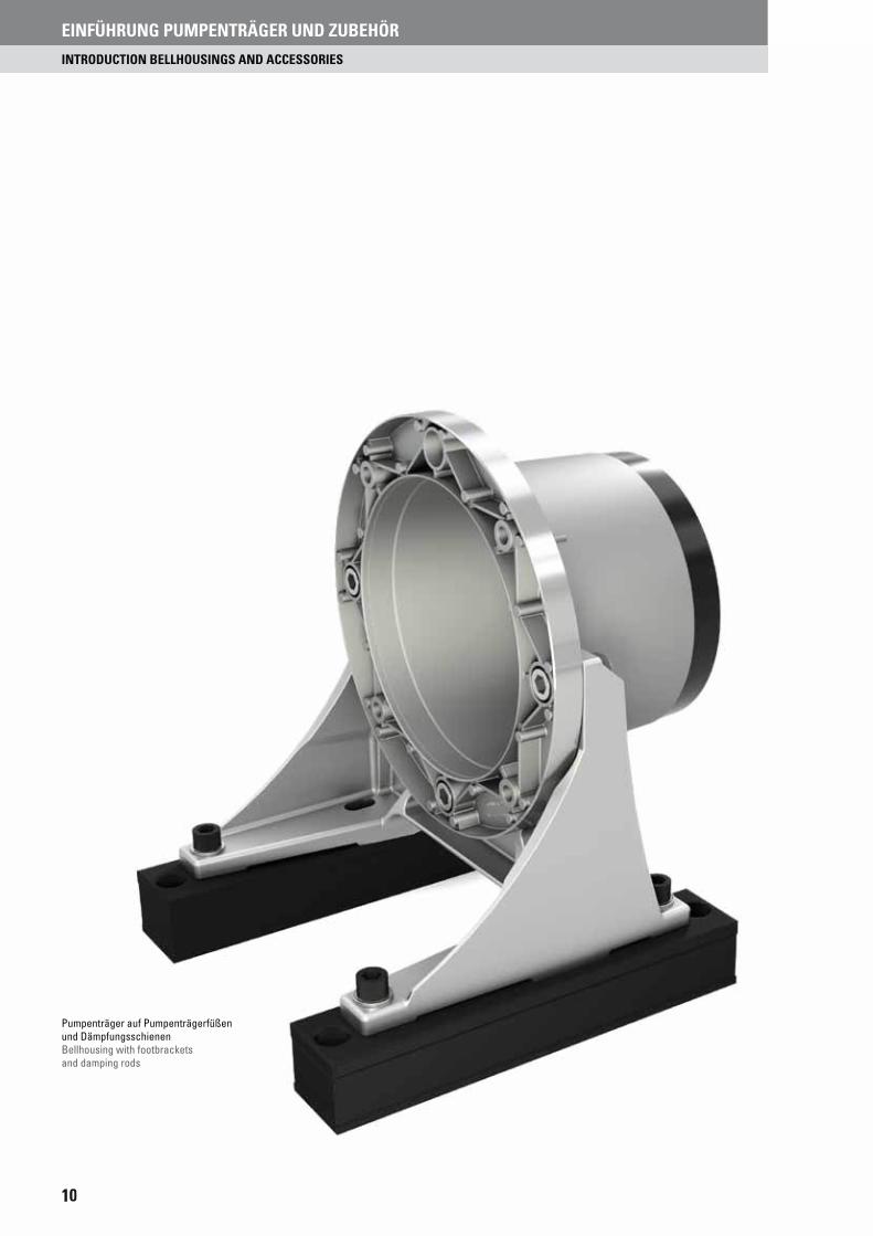
EINFÜHRUNG PUMPENTRÄGER UND ZUBEHÖR
INTRODUCTION BELLHOUSINGS AND ACCESSORIES
Pumpenträger auf Pumpenträgerfüßen und DämpfungsschienenBellhousing with footbrackets and damping rods

11
PUMPENTRÄGER NACH VDMA 24 561 12BELLHOUSINGS ACC. TO VDMA 24 561
PUMPENTRÄGER AUS GRAUGUSS GG-25 17BELLHOUSINGS MADE OF CAST IRON GG-25
PUMPENTRÄGER FÜR ZAHNRADPUMPEN 18BELLHOUSINGS FOR GEAR PUMPS
LECKÖL- UND MONTAGEBOHRUNGEN 22LEAKAGE- AND INSPECTION HOLES
MONTAGEPLATTEN UND PUMPENTRÄGERDICHTUNGEN 23MOUNTING PLATES AND BELLHOUSING GASKETS
KÜHLPUMPENTRÄGER SERIE KPV 24COOLER BELLHOUSINGS SERIES KPV
PUMPENTRÄGERFÜSSE 30FOOTBRACKETS
DÄMPFUNGSRINGE 33DAMPING RINGS
DÄMPFUNGSSCHIENEN 34DAMPING RODS
EINFÜHRUNG PUMPENTRÄGER UND ZUBEHÖR
INTRODUCTION BELLHOUSINGS AND ACCESSORIES
PUMPENTRÄGER UND ZUBEHÖRBELLHOUSINGS AND ACCESSORIES
PUMPENTRÄGER NACH VDMA 24 561BELLHOUSINGS ACC. TO VDMA 24 561
PUMPENTRÄGER AUS GRAUGUSS GG-25BELLHOUSINGS MADE OF CAST IRON GG-25
PUMPENTRÄGER FÜR ZAHNRADPUMPENBELLHOUSINGS FOR GEAR PUMPS
LEL CKÖL- UND MONTAGEBOHRUNGENLELEAKAKAGAGE-E- AANDND IINSPECTIOON HOLES
MOMONTNTAGAGEPEPLALATTTTENEN UUNDND PPUMUMPEPENNTRÄRÄGERDRDICICHTHTUNUNMOMOUNUNTITINGNG PPLALATETES S ANANDD BEBELLLLHOHOUSUSININGG GAGASKSKETETSS
KÜKÜHLHLPUPUMPMPENENTRTRÄGÄGERER SSERERIEIE KKPVPVCOOLER BELE LHLHOUOUSIS NGGS SESERIR ESES KKPVPV
PUMPENTRRÄGÄ ERFÜSSEFOFOOTOTBRB ACKETS
DÄMPFUNGSRINGEDAMPING RINGS
DÄMPFUNGSSCHIENENDAMPING RODS
INTRODUCTION BEL
PUMPENTRÄGER UND ZUBEHÖRBELLHOUSINGS AND ACCESSORIES
PUM
PEN
TRÄG
ER
BEL
LHOU
SIN
GS

12
PUM
PEN
TRÄG
ER
BEL
LHOU
SIN
GSPUMPENTRÄGER NACH VDMA 24 561
BELLHOUSINGS ACC. TO VDMA 24 561
• Abmessungen gemäß VDMA 24 561• Starre und gedämpfte Ausführung mit identischer Längenabstufung• Problemloses Austauschen der Ausführungen untereinander möglich
PRODUKTEIGENSCHAFTENFEATURES
• Dimensions acc. to VDMA 24 561• Rigid and noise damping versions in identical length• Easy interchangeability
PUMPENTRÄGER NACH VDMA 24 561BELLHOUSINGS ACC. TO VDMA 24 561

13
PUM
PEN
TRÄG
ER
BEL
LHOU
SIN
GS
PUMPENTRÄGER NACH VDMA 24 561
BELLHOUSINGS ACC. TO VDMA 24 561
TYPENBEZEICHNUNGMODEL TYPE
RV 250 / * * *
VDMA PumpenträgerVDMA bellhousing
160
200
250
300
350
400
450
550
660
800
Totale Pumpenträgerlänge inkl. DFTotal length of bellhousing incl. DF
Siehe Tabellen Seite 15 – 17See tables page 15 – 17
PumpenanschlussPump connection
XXXX BearbeitungscodeInternal machining code Gedämpfter Pumpenträger
Bellhousing with noise reduction
– Ohne DämpfungsflanschWithout damping flange
DF
Mit integrierter Dämpfung von 250 – 350 (Monobloc)With integrated damping from 250 – 350 (Monobloc)
DF350Mit Dämpfungsflansch ab RV400With damping flange up from RV400DV400
DF401
Interner Zusatzcode für OptionenOptional internal code
ZF Zwischenflansch PumpenseiteIntermediate flange pump side
MZF Zwischenflansch MotorseiteIntermediate flange motor side
ZR Zentrierring PumpenseiteCentering ring pump side
MB InspektionsöffnungInspection hole
LB LeckölbohrungLeakage bore
E EinpressmutterPress nut
GI Mit Schutzgitter für MBIncluding protective grid for MB
ST Mit Stopfen für MBIncluding drain plug for MB
DF/148 / XXXX/
ZULÄSSIGE GEWICHTSBELASTUNG DER GEDÄMPFTEN PUMPENTRÄGERPERMITTED WEIGHT LOAD OF DAMPED BELLHOUSINGS
Für andere Schwerpunktabstände Lx errechnet sich die zulässige Gewichtskraft Fzul aus der Näherungsformel:Other centre to centre distances Lx, the permitted weight load Fzul can be calculated acc. to the approximation formula:
Max. zulässige Betriebstemperatur +80 °C, kurzzeitig +100 °CMax. permitted operating temperature +80 °C, for short periods +100 °C
Fzul = F + 0.5 F (L
-1)Lx
Zulässige Gewichtsbelastung der gedämpften Pumpenträger und Dämpfungsflansche unter Berücksichtigung einer Betriebstemperatur bis 60°C Permitted weight load for dampened bellhousing and damping flange valid for an operating temperature of 60°C
Pumpenträger gedämpftBellhousing noise reduction
DämpfungflanschDamping flange
RV 250 RV 300 RV 350 DV 400 DF 401/1N
Schwerpunktabstand L [mm]Centre to centre spacing [mm] 100 100 100 300 300
Zul. Gewichtskraft F [N]Permitted weight load F [N] 400 1300 1500 2500 2500
Flansch-ØFlange dia.
F
L

14
PUM
PEN
TRÄG
ER
BEL
LHOU
SIN
GSPUMPENTRÄGER NACH VDMA 24 561
BELLHOUSINGS ACC. TO VDMA 24 561
MONOBLOC-PUMPENTRÄGER, GEDÄMPFT NACH VDMA 24 561MONOBLOC-BELLHOUSINGS WITH NOISE DAMPER ACC. TO VDMA 24 561
Hersteller von Hydraulik-Zubehör haben bekanntlich keinen Einfluss auf den Geräuschcharakter einer Pumpe. Die Beeinflussung von Luftschall und Flüs-sigkeitsschall und auch des Körperschalls einer Pumpe obliegt dem Pumpen-konstrukteur.
Der Geräuschcharakter einer Pumpe – bestehend aus Grundfrequenz und Oberwellen – kann besonders unangenehm werden, wenn sich der Körper-schall in andere Bauelemente eines Hydraulikaggregates und hiermit ver-bundene Maschinenelemente fortpflanzt. Die Volumenpulsation und somit Druckpulsation einer Pumpe kann zu besonders unangenehmen Strukturreso-nanzen führen, welche teilweise selbst durch eine Schalldruckpegelmessung in Form des dB(A)-Wertes nicht immer umfassend zum Ausdruck kommen.
Zur Vermeidung der Fortpflanzung dieser Pulsation in andere Bauelemente ist eine weitestgehende Körperschalltrennung zu erwirken. Neben der erfor-derlichen Verwendung einer drehelastischen Kupplung – wie der SPIDEX®-Kupplung – und von Druckschläuchen anstelle von Verrohrungen, geschieht die wesentliche Körperschalltrennung mittels eines gedämpften Pumpenträ-gers. Derartige Dämpfungsflansche enthalten ein Elastomer, welches den metallischen Kontakt zwischen Pumpe und den übrigen Elementen eines Hy-draulikaggregates verhindert.
Die Firma R+L HYDRAULICS fertigt und vertreibt Dämpfungsflansche zur Geräuschreduzierung von Hydraulikaggregaten. Aufgrund der langjährigen Erfahrung hat R+L HYDRAULICS ein gedämpftes Monobloc-Pumpenträgersy-stem (Abb. 4) entwickelt, welches eine wesentliche Vereinfachung gegenüber der üblichen Bauweise bietet. Die Verbindung zwischen Dämpfungsring und Pumpenträger erfolgt jetzt gänzlich ohne Verschraubungen. Vielmehr wird der Pumpenflansch direkt durch eine formschlüssige, anvulkanisierte Elastomer-Verbindung (sowohl in Drehrichtung als auch als Radialabstützung) unmittel-bar mit dem eigentlichen Pumpenträger verbunden.
It is a well-known fact, that manufacturers of hydraulic accessories have no influence at all upon the noise characteristics of a pump. The influence of air sound and liquid sound, but also that of structure-borne noise is incumbent on the pump design engineer himself.
The noise characteristics of a pump – consisting of basic frequency and har-monic waves – can become very annoying, when the structure-borne noise of the hydraulic unit and that of the herewith integrated elements of the machine are propagated. The volume vibration of a pump, and with it the pressure vi-bration, can cause a particularly unpleasant resonance of the structure, which itself cannot always be expressed, even by means of a sound-pressure level monitoring in form of a dB(A)-value.
In order to prevent the propagation of this vibration into other integrated elements as far as possible, the separation of the structure-borne noises is to be achieved. And, apart from having to use a flexible coupling – like a SPIDEX® coupling – and pressure piping instead of the conventional one, the structure-born noises will be essentially separated through the implementation of bell-housings with noise damper. Damper flanges of this type contain an elastomer, which hinders the metallic contact between the pump and the other elements of the hydraulic unit.
The company R+L HYDRAULICS manufactures and distributes damper flanges for the noise reduction of hydraulic units. On account of its many years of ex-perience in this field, R+L HYDRAULICS has developed a monobloc bellhous-ing system with noise damping (Fig. 4), which offers an essential simplification towards the conventional construction. The connection between the noise damper ring and the bellhousing is now totally made without bolting. Rather more, the pump flange is directly combined with the bellhousing by means of a form-conclusive and vulcanised elastomer compound (as well in the sense of rotation as in the radial back-up).
Das Ergebnis ist eine deutlich verbesserte Steifigkeit in Verbindung mit her-vorragenden Dämpfungseigenschaften. Bei einem Monobloc-Pumpenträger mit Motorflanschdurchmesser 300 mm, passend zu einem E-Motor, Baugrösse 132, ergibt sich beispielsweise eine Zerreißkraft von 56 kN. Die höhere Stei-figkeit bewirkt vor allem geringere Verlagerungswerte und somit eine höhere Lebensdauer der Kupplung.
Der Dämpfungseffekt des Monobloc-Pumpenträgers ist nicht nur abhängig von dem speziellen Einsatzfall, sondern auch von dem Geräuschcharakter der Pumpe. Je unangenehmer das Pumpengeräusch, desto höher der Dämpfungs-grad. Das Spektrum der Schallpegelreduzierung liegt in der Regel zwischen 3 dB(A) bei geräuschärmeren Pumpen (Abb. 1) und über 10 dB(A) bei Pumpen (Abb. 2), welche ein unangenehmeres „Geräuscherlebnis“ vermitteln.
The result is a significant improvement of the stiffness, in combination with first rate noise damping characteristics i.e. meaning a tensile strength of 56 kN, in the case of a monobloc-bellhousing with a motor flange diameter of 300 mm, suitable for an E-motor frame size 132. The higher stiffness results especially in lesser misalignments, which go together with a higher service life of the coupling.
The noise damping effect of the monobloc-bellhousing does not only depend on the special field case but also on the noise characteristics of the pump. The more annoying the pump’s noise is, the higher the damping degree will be. The spectrum of soundlevel reduction generally lies between 3 dB(A) in the case of less noisy pumps (Fig. 1) and more than 10 dB(A) by pumps (Fig. 2), which procure a more annoying “noise-experience”.
Abb. 1 Schalldruckpegelmessung FlügelzellenpumpeFig. 1 Sound-pressure level monitoring vane pump
Abb. 2 Schalldruckpegelmessung AußenzahnradpumpeFig. 2 Sound-pressure level monitoring external gear pump
20 001080604060
65
70
75
80
85
RV300-starr
RV300-DF (Monobloc)RV300-DF (Monobloc)
RV300-rigid
Operating pressure p [bar]
Soun
d le
vel [
dB(A
)]Sc
hallp
egel
[dB(
A)]
Betriebsdruck p [bar]
60
65
70
75
80
85 RV250-starr
RV250-DF(Monobloc)
Operating pressure p [bar]Betriebsdruck p [bar]
Soun
d le
vel [
dB(A
)]Sc
hallp
egel
[dB(
A)]
20 40 60 80 100 120 140 160 180 200
RV250-rigid
RV250-DF(Monobloc)

15
PUM
PEN
TRÄG
ER
BEL
LHOU
SIN
GS
PUMPENTRÄGER NACH VDMA 24 561
BELLHOUSINGS ACC. TO VDMA 24 561
3
2
1
Ø d 3
L1
4
F
L
Ø d
H2
G
G1
L1
Ø d1Ø D4
F
Ø D3
2
1
L
2
Ø DØ D
Ø D
Ø DØ DØ D
MONOBLOC-SYSTEM, GEDÄMPFTE AUSFÜHRUNGMONOBLOC-SYSTEM, NOISE REDUCTION VERSION
Ø D1 = 250 – 350 mm Ø D1 = 250 – 350 mm
RV.../.../... RV.../.../.../DF
Pumpenträger mit Flansch-Ø D1 = 160 mm nach VDMA 24 561 nur in starrer Ausführung. Ausführung mit Flansch-Ø D1 = 200 mm mit verschraubtem Dämpfungsflansch auf Anfrage.Bellhousings with flange-Ø D1 = 160 mm acc. to VDMA 24 561 only in rigid version. Noise reduction version with flange-Ø D1 = 200 mm with screwed damping flange on request.
Abb. 3 Pumpenträger, starr, nach VDMA 24 561Fig. 3 Bellhousings, rigid, acc. to VDMA 24 561
Abb. 4 Monobloc-Pumpenträger, gedämpft, nach VDMA 24 561 Formschlüssige Verbindung ohne VerschraubungFig. 4 Monobloc-Bellhousings with noise damper, acc. to VDMA 24 561 Form fitting without screw joint
Pumpen-trägertypType ofbellhousing
E-MotorBaugrößeFrame size
LeistungPower
WellenendeShaftend
FußflanschFootbracket
AbmessungenDimensions
[kW]D x I [mm]
D1[mm]
D2[mm]
D3[mm]
D4[mm]
d1[mm]
d2[mm]
d3[mm]
L[mm]
L1[mm]
F[mm]
G[mm]
G1 H2[mm]
RV 160/80/...71
0.2514 x 30 PTFL160 160 130 110 110 21 107 –
8013 4 9 M8 8.5
RV 160/90/... 0.37 90RV 200/100/... 80 0.55 – 0.75 19 x 40
PTFL200 200 165 130 145 36129
–
100
16 5 11 M10 12.5RV 200/110/...
90 S+L 1.1 – 1.5 24 x 50
110RV 200/118/... 118RV 200/124/...
128124
RV 200/140/... 140RV 250/120/... 100 L 2.2 – 3.0
28 x 60
PTFL250
250 215 180 190 45178
172
120
19 5 14 M12 14.5
RV 250/124/...
112 M 4.0 PTFS250
124RV 250/128/... 128RV 250/135/... 135RV 250/148/... 172 148RV 250/175/... 176 175RV 300/144/... 132 S 5.5
38 x 80 PTFL300PTFS300 300 265 230 234 50
222
217
144
20 5 14 M12 18.0RV 300/150/...
132 M 7.5221
150RV 300/155/... 155RV 300/168/... 220 168RV 300/196/... 217 196RV 350/188/... 160 M+L 11.0 – 15.0 42 x 110
PTFS350 350 300 250 260
41 236231
188
26 6 18 M16 18.0RV 350/204/...
180 M+L 18.5 – 22.0 48 x 11053 234 204
RV 350/228/... 70 232 228 228RV 350/256/... 90 230 226 256
STARRE AUSFÜHRUNG RVRIGID VERSION RV
Ø D1 = 160 – 350 mm Ø D1 = 160 – 350 mm

16
PUM
PEN
TRÄG
ER
BEL
LHOU
SIN
GS
STARRE AUSFÜHRUNG RVRIGID VERSION RV
Ø D1 = 400 – 800 mm Ø D1 = 400 – 800 mm
GEDÄMPFTE AUSFÜHRUNG, 2-TEILIGNOISE REDUCTION VERSION, 2-PIECE
Ø D1 = 400 – 800 mm Ø D1 = 400 – 800 mm
RV.../.../...
RV.../.../.../DF350RV.../.../.../DF401
**Nicht in der VDMA-Norm enthalten **Not included in the VDMA-Standard
F
L
G
F
L
Ø d 2
H2
Ø D 4
Ø D 3
2
1
Ø DØ D
L 1
G 1
Ø d1
Ø d 3
Ø d 3
L 1
4Ø D
3
2
1
Ø DØ DØ D
RV.../.../.../DV400
Ab Größe 450, 8 BohrungenFrom Size 450, 8 bores
Pumpen-trägertypType ofbellhousing
E-MotorBaugrößeFrame size
LeistungPower
[kW]
WellenendeShaftend
D x I[mm]
FußflanschFootbracket
AbmessungenDimensions
D1
[mm]
D2
[mm]
D3
[mm]
D4
[mm]
d1min
[mm]
d1min
[mm]
d2
[mm]
d3
[mm]
L
[mm]
L1
[mm]
F
[mm]
G
[mm]
G1 H2
[mm]
RV 400/204/...200 L 30 55 x 110 PTFS400 400 350 300 300 50
50(DF350)
50(DV400)
80(DF401)
265
260(DF350)
283(DV400)
362(DF401)
204
26 6 18 M16 22RV 400/228/... 262 228
RV 400/256/... 259 256
RV 450/234/... 225 S 37
60 x 140 PTFS450 450 400 350 350 80
301 234
26 6 18 M16 20RV 450/262/...
225 M45 297 262
RV 450/285/...276
285
RV 450/315/... 315
RV 550/248/... 250 M 55 65 x 140
PTS5500 550 500 450 450 80
362 248
26 6 18 M16 20RV 550/265/...
280 S+M 75–90 75 x 140
360 265
RV 550/275/... 358 275
RV 550/295/... 354 295
RV 550/315/... 351 315
RV 660/310/...315 S+M+L
110–13280 x 170 PTS660 660 600 550 550 80
414 310
32 6 23 M20 20RV 660/330/...160–200
409 330
RV 660/345/... 408 345
RV 800/315/...** 355 L 250–315 95 x 170
— 800 740 680 680 125
468 315
60 10 23 M20 35RV 800/335/...**
400 L 355–400 100 x 210
474 335
RV 800/350/...** 485 350
RV 800/443/...** 490 443
Andere Dämpfungskombinationen und separate Dämpfungsflansche auf AnfrageOther damping combinations and separate damping flanges on request
PUMPENTRÄGER NACH VDMA 24 561
BELLHOUSINGS ACC. TO VDMA 24 561

17
PUM
PEN
TRÄG
ER
BEL
LHOU
SIN
GSPumpen trägertypType of bellhousing
E-Motor BaugrößeFrame size
LeistungPower
[kW]
WellenendeShaft end
D x l[mm]
FußflanschtypType of foot
bracket
AbmessungenDimensions
[mm]
GewichtWeight
[kg]D1 D2 D3 D4 D5 D6 T L L1 L2 L3 N G G1
GG-RV250/175/… 112 M 4.0 28 x 60 GG-PTFS 250 250 215 180 190 40 176 10 175 19 14 5 4 14 M12 10.50GG-RV300/144/... 132 S 5.5
38 x 80 GG-PTFS 300 300 265 230 23450 222
10144
20 16 5 4 14 M1213.00
GG-RV300/196/... 132 M 7.5 75 218 196 15.00GG-RV350/188/... 160 M+L 11.0 + 15.0 42 x 110
GG-PTFS 350 350 300 250 260
40 245
10
188
26 18 6 4 18 M16
20.50GG-RV350/204/...
180 M+L 18.5 + 22.0 48 x 11050 244 204 21.00
GG-RV350/228/... 65 243 228 22.00GG-RV350/256/... 85 241 256 23.50GG-RV400/204/...
200 L 30.0 55 x 110 GG-PTFS 400 400 350 300 300 45284
10204
26 20 6 4 18 M1628.00
GG-RV400/228/... 283 228 28.50GG-RV450/234/... 225 S 37.0
60 x 140 GG-PTFS 450 450 400 350 35050 332
10234
26 20 6 8 18 M1636.00
GG-RV450/262/... 225 M 45.0 80 330 262 37.50GG-RV550/248/… 250 M 55.0 65 x 140
GG-PTFS 550 550 500 450 450 80431
10248
26 20 6 8 18 M1653.00
GG-RV550/265/... 280 S+M 75.0 + 90.0 75 x 140 430 265 53.50GG-RV660/330/... 315 S+M+L 160.0 + 200.0 80 x 170 GG-PTFS 660 660 600 550 550 80 526 10 330 32 24 6 8 23 M20 86.00
PUMPENTRÄGER GG-PT BELLHOUSINGS GG-PT
Pumpenträger aus Grauguss sind speziell für folgende Anwendungen entwickelt worden:
- Hohe Belastungen- Mobilhydraulik- Bergbau, Offshore- Servomotorische Antriebe
Aufgrund der hohen Masse gute Geräuschdämpfungseigenschaften.
Starre Ausführung GG-RVWerkstoff: EN-GJL-250Ø D1 = 250 – 660 mmAb Lager verfügbarAndere Größen auf AnfrageMontageanleitung beachten
Leckage- bzw. Montagebohrungen sind bei der Bestellung anzugeben.Leackage- or inspection holes respectively have to be specified with the order.
PUMPENTRÄGER AUS GRAUGUSS GG-25BELLHOUSINGS MADE OF CAST IRON GG-25
Ø D
4
Ø D
1
Ø D
3 F9
Ø D
5
Ø D
6
Ø D2
Nx Ø G Nx G1
Bellhousings made of cast iron are especially developed for the following applications:
- High loads- Mobile hydraulic- Mining, Offshore- Servomotorical drives
Based on the high weight, good noise reduction performance.
Rigid version GG-RVMaterial: EN-GJL-250Ø D1 = 250 – 660 mmAvailble from stockOther sizes on requestConsider operation manual
PUMPENTRÄGER AUS GRAUGUSS GG-25
BELLHOUSINGS MADE OF CAST IRON GG-25

18
PUM
PEN
TRÄG
ER
BEL
LHOU
SIN
GSPUMPENTRÄGER FÜR ZAHNRADPUMPEN
BELLHOUSINGS FOR GEAR PUMPS
• Motorbundhöhe gemäß VDMA 24 561• Kombinierbar mit Fußflanschen nach VDMA 24 561• Motorflanschdurchmesser von 160 – 400 mm
PRODUKTEIGENSCHAFTENFEATURES
• Height of motor flange acc. to VDMA 24 561• Optional combination with footbrackets acc. to VDMA 24 561• Motor flange diameter from 160 – 400 mm
PUMPENTRÄGER FÜR ZAHNRADPUMPENBELLHOUSINGS FOR GEAR PUMPS

19
PUM
PEN
TRÄG
ER
BEL
LHOU
SIN
GS
PUMPENTRÄGER FÜR ZAHNRADPUMPEN
BELLHOUSINGS FOR GEAR PUMPS
TYPENBEZEICHNUNGMODEL TYPE
RV 250 / ZFV
PumpenanschlussPump connection
XXXX Interner BearbeitungscodeInternal machining code
Interner Zusatzcode für OptionenOptional internal code
ZF Zwischenflansch PumpenseiteIntermediate flange pump side
MZF Zwischenflansch MotorseiteIntermediate flange motor side
ZR ZentrierringCentering ring
MB InspektionsöffnungInspection hole
LB Leckölbohrung Leakage bore
E EinpressmutterPress nut
B14 /110 / XXXX /
PumpenträgerBellhousing
Flansch-ØFlange-Ø
160200250300350400
PumpenträgerlängeLength of bellhousing
Siehe TabellenSee tables
MotorbauformFrame size
– IM B 35
B 14 IM B 14
TYPENBEZEICHNUNGMODEL TYPE
M1 G
G1
M2
M
Ø d1
2xG2
M1G
G1
M
4xG2
Fig. 1
Fig. 4
2xG2
Fig. 2 Fig. 3
M1G
G1
M2
M
G
G1
M2
MØ d1
2xG2
Ø d1
M2
L1
L
Ø d1 Ø D1
Ø D2
Ø D3
Ø d2
Ø D4
MotorseiteMotor side
PumpenseitePump side

20
PUM
PEN
TRÄG
ER
BEL
LHOU
SIN
GS
Typ Type
Bohrbild Pump con. D1 D2 D3 D4 d1 d2 L L1 F G G1 G2 M M1 M2
RV160/70/401 Fig. 1
160 130 110 110
32.0 107 70
13 4 9
M82 x M8 40.0 40.0 10.35
RV160/70/468 Fig. 3 22.0 2 x M6 66.0 25.5 33.00RV160/80/401 Fig. 1 32.0 107
80
2 x M8 40.0 40.0 10.35RV160/80/401/B14 32.0 Ø9RV160/80/448/ZFV*
Fig. 425.4
–M8
4 x M6 72.0 52.4 26.20RV160/80/448/B14/ZFV* 25.4 Ø9RV160/80/453/B14/ZFV* 30.0 73.0 56.0 24.50RV160/90/401 Fig. 1 32.0 107
90
M8 2 x M8 40.0 40.0 10.35RV160/90/401/B14 32.0 Ø9RV160/90/448/ZFV*
Fig. 4
25.4–
M84 x M6 72.0 52.4 26.20
RV160/90/448/B14/ZFV* 25.4
Ø9
24.50RV160/90/453/B14/ZFV* 30.0 73.0 56.0RV160/95/441/B14/ZFV* 80.0 – 95
4 x M8
100.0 72.0 34.50RV160/95/446/B14/ZFV* 36.5 96.2 71.5 32.70
80.0
– 105
100.0 72.0 34.50RV160/105/446/B14/ZFV* 36.5 96.2 71.5 32.70
25.4 72.0 52.4 26.20RV160/110/441/B14/ZFV* 80.0 100.0 72.0 34.50RV160/110/446/B14/ZFV* 36.5 96.2 71.5 32.70
Typ Type
Bohrbild Pump con. D1 D2 D3 D4 d1 d2 L L1 F G G1 G2 M M1 M2
RV200/80/401 Fig. 1
200 165 130 145
32.00
129
80
16 5 11 M10
2 x M8 40.0 40.0 10.35RV200/80/448 Fig. 4 25.40 4 x M6 72.0 52.4 26.20RV200/80/453 30.00 73.0 56.0 24.50RV200/80/468 Fig. 3 22.00 2 x M6 66.0 25.5 33.00RV200/80/493 Fig. 4 33.00 4 x M6 72.0 52.4 26.20RV200/90/401 Fig. 1 32.00
90
2 x M8 40.0 40.0 10.35RV200/90/448 Fig. 4 25.40 4 x M6 72.0 52.4 26.20RV200/90/453 30.00 73.0 56.0 24.50RV200/90/468 Fig. 3 22.00 2 x M6 66.0 25.5 33.00RV200/90/493
Fig. 4
33.00 4 x M6 72.0 52.4 26.20RV200/96/439/ZFV* 50.00
– 96
2 x M10 60.0 60.0 14.50RV200/96/441/ZFV* 80.00 4 x M8 100.0 72.0 34.50RV200/96/446/ZFV* 36.50 96.2 71.5 32.70RV200/96/459/ZFV* 36.50 4 x M6RV200/100/404 52.00
129 100 2 x M862.0 62.0 23.30RV200/100/405 63.00
RV200/100/474 32.00 52.0 52.0 19.50RV200/100/476 45.24RV200/106/439/ZFV* 50.00
– 106
2 x M10 60.0 60.0 14.50RV200/106/441/ZFV* 80.00 4 x M8 100.0 72.0 34.50RV200/106/446/ZFV* 36.50 96.2 71.5 32.70RV200/106/459/ZFV* 36.50 4 x M6RV200/110/404 52.00 129 110 2 x M8 62.0 62.0 23.30RV200/110/405 63.00
Typ Type
Bohrbild Pump con. D1 D2 D3 D4 d1 d2 L L1 F G G1 G2 M M1 M2
RV250/110/401Fig. 1
250 215 180 190
32.0
179
110
19 5 14 M12
2 x M8 40.0 40.0 10.35RV250/110/402 50.0 72.0 72.0 28.60RV250/110/439 2 x M10 60.0 60.0 14.50RV250/110/441
Fig. 4
80.0 4 x M8 100.0 72.0 34.50RV250/110/446 36.5 96.2 71.5 32.70RV250/110/448 25.4
4 x M672.0 52.4 26.20
RV250/110/453 30.0 73.0 56.0 24.50RV250/110/459 36.5 96.2 71.5 32.70RV250/110/462 4 x M8RV250/110/493 33.0 4 x M6 72.0 52.4 26.20RV250/110/828 77.0 4 x M8 96.2 71.5 32.70RV250/116/401
Fig. 132.0
116
2 x M8 40.0 40.0 10.35RV250/116/402 50.0 72.0 72.0 28.60RV250/116/439 2 x M10 60.0 60.0 14.50RV250/116/441
Fig. 4
80.0 4 x M8 100.0 72.0 34.50RV250/116/446 36.5 96.2 71.5 32.70RV250/116/448 25.4
4 x M672.0 52.4 26.20
RV250/116/453 30.0 73.0 56.0 24.50RV250/116/459 36.5 96.2 71.5 32.70RV250/116/462 4 x M8RV250/116/493 33.0 4 x M6 72.0 52.4 26.20RV250/116/828 77.0 4 x M8 96.2 71.5 32.70RV250/120/404
Fig. 1
52.0
178120
2 x M8 62.0 62.0 23.30RV250/120/405 63.0RV250/124/404 52.0 124RV250/124/405 63.0
Motorflansch – Ø 160 mm Motor flange – Ø 160 mm Abmessungen Dimensions [mm]
Motorflansch – Ø 200 mm Motor flange – Ø 200 mm
Motorflansch – Ø 250 mm Motor flange – Ø 250 mm
Abmessungen Dimensions [mm]
Abmessungen Dimensions [mm]
Achtung! * Nicht für öldichten Einbau geeignet Caution! * Don’t use for oil tight assembly
PUMPENTRÄGER FÜR ZAHNRADPUMPEN
BELLHOUSINGS FOR GEAR PUMPS

21
PUM
PEN
TRÄG
ER
BEL
LHOU
SIN
GS
Typ Type
Bohrbild Pump con. D1 D2 D3 D4 d1 d2 L L1 F G G1 G2 M M1 M2
RV300/130/405 Fig. 1
300 265 230 234
63.0
223
130
20 5 14 M12
2 x M8 62.0 62.0 23.3RV300/130/439 50.0 2 x M10 60.0 60.0 14.5RV300/130/441
Fig. 480.0 4 x M8 100.0 72.0 34.5
RV300/130/446 36.5 96.2 71.5 32.7RV300/130/459 4 x M6RV300/130/499 Fig. 2 50.0 2 x M10 60.0 60.0 14.5RV300/144/425
Fig. 4
65.0
144
4 x M8 110.0 110.0 32.5RV300/144/444
50.84 x M10 137.0
98.445.0
RV300/144/447 4 x M8 128.0 42.9RV300/144/465 4 x M10RV300/162/403/ZFV* 125.0 –
162
206.0 136.0 103.0RV300/162/419/ZFV* 60.0 4 x M12 154.0 127.0 48.0RV300/162/423/ZFV* 85.0 4 x M10 164.0 124.0 50.0RV300/162/426/ZFV* 80.0 4 x M12 150.0 150.0 43.2RV300/162/427/ZFV* 63.5 188.0 143.0 64.3RV300/162/442/ZFV* 105.0 4 x M10 145.0 102.0 48.0RV300/162/443/ZFV* 60.0 4 x M12 148.0 127.0RV300/162/444/ZFV* 50.8 4 x M10 137.0 98.4 45.0RV300/162/449/ZFV* 60.3 149.4 114.3 49.3RV300/162/451/ZFV* 63.5 4 x M12 196.0 142.8 65.1RV300/162/475/ZFV* 160.0 4 x M16 200.0 160.0 70.7
Typ Type
Bohrbild Pump con. D1 D2 D3 D4 d1 d2 L L1 F G G1 G2 M M1 M2
RV350/173/404 Fig. 1
350 300 250 260
52.0
238 173
26 6 18 M16
2 x M8 62.0 62.0 23.3RV350/173/405 63.0RV350/173/417 Fig. 4 80.0 4 x M10 130.0 100.0 41.0RV350/173/439 Fig. 1 50.0 2 x M10 60.0 60.0 14.5RV350/173/441
Fig. 4
80.0 4 x M8 100.0 72.0 34.5RV350/173/442 105.0 4 x M10 145.0 102.0 48.0RV350/173/444 50.8 137.0 98.4 45.0RV350/173/446 36.5 4 x M8 96.2 71.5 32.7RV350/173/447 50.8 128.0 98.4 42.9RV350/173/459 36.5 4 x M6 96.2 71.5 32.7RV350/173/499 Fig. 2 50.0 2 x M10 60.0 60.0 14.5RV350/205/403/ZFV*
Fig. 4
125.0
– 205
4 x M10 206.0 136.0 103.0RV350/205/419/ZFV* 60.0 4 x M12 154.0 127.0 48.0RV350/205/423/ZFV* 85.0 4 x M10 164.0 124.0 50.0RV350/205/426/ZFV* 80.0 4 x M12 150.0 150.0 43.2RV350/205/427/ZFV* 63.5 188.0 143.0 64.3RV350/205/442/ZFV* 105.0 4 x M10 145.0 102.0 48.0RV350/205/443/ZFV* 60.0 4 x M12 148.0 127.0RV350/205/444/ZFV* 50.8 4 x M10 137.0 98.4 45.0RV350/205/449/ZFV* 60.3 149.4 114.3 49.3
Typ Type
Bohrbild Pump con. D1 D2 D3 D4 d1 d2 L L1 F G G1 G2 M M1 M2
RV400/168/441
Fig. 4 400 350 300 300
80.0284 168
26 6 18 M16
4 x M8 100.0 72.0 34.5RV400/168/447 50.8 128.0 98.4 42.9RV400/168/481 100.0 4 x M10 132.0 88.4 44.2RV400/196/441 80.0
281 196
4 x M8 100.0 72.0 34.0RV400/196/442 105.0 4 x M10 145.0 102.0 48.0RV400/196/443 60.0 4 x M12 148.0 127.0RV400/196/444 50.8 4 x M10 137.0 98.4 45.0RV400/196/447 4 x M8 128.0 42.9RV400/196/449 60.3 4 x M10 149.4 114.3 49.3RV400/196/465 50.8 128.0 98.4 42.9
Motorflansch – Ø 400 mm Motor flange – Ø 400 mm
Motorflansch – Ø 350 mm Motor flange – Ø 350 mm
Motorflansch – Ø 300 mm Motor flange – Ø 300 mm Abmessungen Dimensions [mm]
Achtung! * Nicht für öldichten Einbau geeignet Caution! * Don’t use for oil tight assembly
PUMPENTRÄGER FÜR ZAHNRADPUMPEN
BELLHOUSINGS FOR GEAR PUMPS
Abmessungen Dimensions [mm]
Abmessungen Dimensions [mm]

22
PUM
PEN
TRÄG
ER
BEL
LHOU
SIN
GS
LECKÖL- UND MONTAGEBOHRUNGENLEAKAGE- AND INSPECTION BORES
Ø D E-MotorBaugruppe
E-motor
LeckölbohrungLeckage bore
MontagebohrungInspection bore
L1[mm]
D1[mm]
L2[mm]
D2[mm]
160 71 28
7.5
3729
200 80 / 90 36 53250 100 / 112 43 69
48
300 132 45 92350 160 / 180
51124
400 200450 225
160550 250 / 280660 315 60
TYPENBEZEICHNUNGMODEL TYPE
B14= E-Motor-Bauform IMB14 ohne Angabe = E-Motor-Bauform IMB5/V1B14= E-Motor type IMB14without specification = E-Motor type IMB5/V1
LB = Leckölbohrung Leckage boreMB = Montagebohrung Inspection boreGI = MB mit Gitter MB with gridST = MB mit Stopfen MB with plug
Pumpenträger ØBellhousing Ø
PumpenträgerlängeLength of bellhousing
BohrbildBore pattern
LECKÖL- UND MONTAGEBOHRUNGEN
LEAKAGE- AND INSPECTION BORES
POSITIONIERUNG VON LECKÖLBOHRUNGEN (LB) UND MONTAGEBOHRUNGEN (MB) MIT GITTER (GI) UND STOPFEN (ST)POSITIONING OF LEAKAGE (LB) AND INSPECTION BORES (MB) WITH GRIDS (GI) AND PLUGS (ST)
RV350 / 188 / 200 / LB / MB / GI / B14
Bei mehrteiligen Pumpenträgern werden Montagebohrungen auf LX/2 eingebracht.
TECHNISCHE DATENTECHINCAL DATA

23
PUM
PEN
TRÄG
ER
BEL
LHOU
SIN
GS
PUMPENTRÄGERDICHTUNGENBELLHOUSING GASKETS
MONTAGEPLATTENMOUNTING PLATES
Typ Type
Dichtung 1 Gasket 1
Dichtung 2 Gasket 2
AbmessungenDimensions
[mm]
L0 L1 L2 L3 L4 D0 D1 D2 D3 D4 D5 D6 R M W0 W1
MP 200 D 200 NBR D 325 NBR 325 190 140 8 16 250 225 165 147 9.5 11 20 60 M10 – 15MP 250 D 250 NBR D 355 NBR 350 190 140 8 16 300 275 215 192 9.5 14 20 60 M12 25 40MP 300 D 300 NBR D 420 NBR 420 225 150 8 16 360 330 265 236 14 14 20 90 M12 25 40MP 350 D 350 NBR D 475 NBR 475 255 160 10 20 410 380 300 262 14 18 25 110 M16 25 40
Bei V1-Anordnung Durchführung der Druckleitung zur einfachen Montage und Demontage der Pumpen-Motoren-Einheit.For leading through pressure line, thus easy mounting and dismounting of the unit pump-bellhousing-motor.
DICHTUNG 1 GASKET 1
Typ Type
AbmessungenDimensions
[mm]
D D1 D2 D3D 140 NBR 140 115 97 10D 160 NBR 160 130 112 10D 200 NBR 200 165 147 12D 250 NBR 250 215 193 14D 300 NBR 300 265 237 14D 350 NBR 350 300 263 19D 400 NBR 400 350 303 19D 450 NBR 450 400 353 19D 550 NBR 550 500 453 19D 660 NBR 660 600 554 24
Montage zwischen Pumpenträger und MontageplatteMounting between bellhousing and mounting plate
MATERIAL: NBR, Gummikork und Pappe
MATERIAL: NBR, rubberized cork and paper
DICHTUNG 2 GASKET 2
Typ Type
AbmessungenDimensions
[mm]
L0 L1 D0 D1 D2 R
D 325 NBR 325 250 200 140 10 60D 355 NBR 350 300 250 140 10 60D 420 NBR 420 360 300 150 15 90D 475 NBR 475 410 350 160 20 110
Montage zwischen Montageplatte und BehälterdeckelMounting between mounting plate andtank lid
MONTAGEPLATTEN UND PUMPENTRÄGERDICHTUNGEN
MOUNTING PLATES AND BELLHOUSING GASKETS

24
PUM
PEN
TRÄG
ER
BEL
LHOU
SIN
GSKÜHLPUMPENTRÄGER, SERIE KPV
COOLER BELLHOUSINGS, SERIES KPV
• Abmessungen gemäß VDMA 24 561• Gedämpfte Ausführung mit identischer Längenabstufung• Problemloser Austausch mit gedämpften Pumpenträgern
gemäß VDMA 24 561• Kombinierbar mit Fußflanschen nach VDMA 24 561
PRODUKTEIGENSCHAFTENFEATURES
• Dimensions acc. to VDMA 24 561• Noise damping versions in identical lengths• Easy replacement of dampened bellhousing acc. to VDMA 24 561• Optional combination with footbrackets acc. to VDMA 24 561
KÜHLPUMPENTRÄGER, SERIE KPVCOOLER BELLHOUSINGS, SERIES KPV

25
PUM
PEN
TRÄG
ER
BEL
LHOU
SIN
GS
KÜHLPUMPENTRÄGER, SERIE KPV
COOLER BELLHOUSINGS, SERIES KPV
TYPENBEZEICHNUNGMODEL TYPE
KPV 250 /
KühlpumpenträgertypType of cooler bellhousing
0.55–1.5 kW KPV2002.2–4 kW KPV2505.5–7.5 kW KPV30011–22 kW KPV350
DFD 28120 / XXXX
KühlpumpenträgerlängenLengths of cooler bellhousing
KPV200
100110118124128
KPV250
120124128135148175
KPV300
144150155168196
KPV350
188204228256
Kennzahl für PumpenanschlussBore code for pump connection
XXXX Interne NummerInternal code
Lüfterrad-Wellen-ØFan-shaft-Ø
D19 0.55–0.75 kWD24 1.1–1.5 kWD28 2.2–4 kWD38 5.5–7.5 kWD42 11–15 kWD48 18.5–22 kW
AusführungVersion
DF GedämpftDamped
Kühlleistung der Serie KPV in Korrelation zur installierten Motorleistung
• Die zulässige Nenndrehzahl(1) für die Antriebsmaschine beträgt 1500 1/min. Andere Drehzahlen nur nach Rücksprache mit dem Hersteller.
• Schallpegel(2) der gedämpften Ausführung gemessen mit Pumpenträger und E-Motor in 1 m Abstand zum Prüfling. Die angegebenen Werte sind als Anhaltswerte zu betrachten, da der tatsächliche Schallpegel abhängig vom eingesetzten Elektromotor schwankt.
• Drehrichtung der Pumpe grundsätzlich rechts (auf die Pumpenwelle gesehen).
Cooling capacity of the series KPV in correlation to the capacity of the installed engine.
• Nominal rotation (1) of driven machine 1500 1/min. In case of different rpm please contact the manufacturer.
• Noise levels (2) of damped version are measured with bellhousing and electric motor. Distance to the tested object 1 m. The a. m. values of noise level will be various depending on used electric motor.
• Direction of pump rotation always clockwise (looking on pump shaft).
TECHNISCHE DATEN TECHNICAL DATA
BetriebsdruckWorking pressure
LastwechselLoad cycle
Max. statischer DruckMax. static pressure
16 bar 1 x 10⁶ ; f = 2 Hz 40 bar
TypType
KühlleistungCooling power
Leistung E-Motor E-engine power
[kW]
LuftdurchsatzAir flow
LeistungsaufnahmeFan input power
Schallpegel (2)
Noise level (2)Korrelation Kühlleistung/Motorleistung
Correlation cooling power/E-engine power
p [kW] t=40k n=1500 1/min(1) [m3/h] [W] [dB(A)] [%]KPV200 0.95 0.55 – 1.50 72 20 52 63 – 1100KPV250 2.10 2.20 – 14.00 260 30 58 53 – 195KPV300 3.22 5.50 – 17.50 430 90 69 43 – 159KPV350 5.15 11.00 – 122.00 780 140 70 23 – 146

26
PUM
PEN
TRÄG
ER
BEL
LHOU
SIN
GSKÜHLPUMPENTRÄGER, SERIE KPV
COOLER BELLHOUSINGS, SERIES KPV
Kühlpumpenträger haben mittlerweile breiten Eingang in die Ölhydraulik ge-funden. Die Firma R+L HYDRAULICS GmbH stellt eine innovative Baureihe von Kompakt-Kühlern vor, welche über ein reines ‚face-lifting‘ weit hinausgeht und dem Anwender wesentliche Vorteile bietet – die Kühlpumpenträgerserie KPV.
Nachdem die anfangs auf dem Markt erhältlichen Kühlpumpenträger in der Regel mit einem Rippenrohr als Wärmetauscher bestückt waren, was diese – abgesehen von der unbefriedigenden Kühlleistung – überwiegend auf die Leckölkühlung beschränkte, ist die Verwendung prismatischer Kühlelemente heute Stand der Technik. R+L HYDRAULICS hat als erster Hersteller katalog-mäßige Kühlpumpenträger mit prismatischen Standard-Kühlelementen ein-gesetzt. Bei dem hierdurch möglichen Einbau der Kühler in die überwiegend drucklose Rücklaufleitung kann es jedoch bei bestimmten Konstellationen zu Druckspitzen kommen, welche mit herkömmlichen Druckmessgeräten nicht zu ermitteln sind.
Dieses ist z.B. häufig der Fall, wenn ein druckbeaufschlagter Zylinder im Milli-sekundenbereich durch ein Elektromagnetventil zur Rücklaufleitung hin entla-stet wird. Durch Massenträgheit und Reibung ist es vielfach nicht möglich, die entstehende Druckspitze vom Kühler fernzuhalten, was in der Vergangenheit bei periodisch wiederkehrenden Druckspitzen gelegentlich zum Ausfall des Wärmetauschers führte.
Cooler bellhousings are meanwhile well established in the oil hydraulic. The company R+L HYDRAULICS GmbH presents an innovative series of compact coolers, which reaches far beyond a plain “face-lifting” and offers the users substantial advantages – the cooler bellhousing series KPV.
Since the first cooler bellhousings on the market were usually equipped with a finned tube as heat exchanger, which – regardless of the unsatisfactory coo-ling power – chiefly limited to leakage oil cooling, is the application of prisma-tic cooling elements state-of-the-art today. The herewith given possibility to build the cooler into the mainly pressureless return pipe can however be the cause for pressure peaks, which cannot be detected with customary pressu-re measuring devices. R+L HYDRAULICS, that was the first manufacturer to bring in cooler bellhousings with prismatic standard cooling elements from catalogue.
This is often the case, for instance, when a cylinder under pressure will be unloaded within milliseconds by means of an electromagnetic valve to the return pipe. Because of inertia and friction, it is frequently not possible to pro-tect the cooler from the resulting pressure peak, which has in the past led to occasional breakdowns of the temperature exchanger in the case of recurring pressure peaks.
Bei der Konzeption der neuen KPV-Baureihe war es deshalb oberstes Gebot, ein Kühlelement zu integrieren, welches ohne Einbußen in der Kühlleistung dynamischen Druckbelastungen standhält. Mittels dynamischer Dauerbela-stungversuche wurde ein Kühlelement entwickelt, welches der anwenderbe-zogenen Vorgabe von Druckspitzen bis zu einer Höhe von 16 bar dauerhaft standhält (Abb. 1).
It became therefore top priority, during the development of the new series KPV, to integrate a cooling element, which withstands dynamic pressure loads without loss of cooling power. According to users’ requirements and by means of dynamic fatigue strain tests, a cooling element has been developed, which continually withstands pressure peaks up to 16 bars (Fig. 1).
Abb. 1) Dauerbelastungs-Druckversuche mit Kühlelementen für die R+L HYDRAULICS-Serie KPV bei 16 bar mit 1 x 10⁶ Lastspielen und f = 2 Hz
Fig. 1) Dynamic fatigue strain tests with cooling elements for the R+L HYDRAULICS-series KPV at 16 bars with 1 x 10⁶ stress cycles and f = 2 Hz
Kühlpumpenträger, Serie KPVCooler bellhousing, series KPV
Abb. 2) Austauschbarkeit der Bauweisen starr, gedämpft, gekühlt nach VDMA 24 561
Fig. 2) Interchangeability of configurations rigid, damped, cooled acc. to VDMA 24 561
KÜHLPUMPENTRÄGER VDMA-KOMPATIBEL,RESISTENT GEGEN DRUCKSPITZENCOOLER BELLHOUSING VDMA COMPATIBLE, RESISTANT TO PRESSURE PEAKS
00
10
20
30
40
015
Inpu
t 1 b
ar
sec1 2 3 4 5
DYNAMISCHE DRUCKBESTÄNDIGKEITDYNAMIC RESISTANCE TO PRESSURE
gekühltcooled
gedämpftdamped
L
H1H1
27
PUM
PEN
TRÄG
ER
BEL
LHOU
SIN
GS
KÜHLPUMPENTRÄGER, SERIE KPV
COOLER BELLHOUSINGS, SERIES KPV
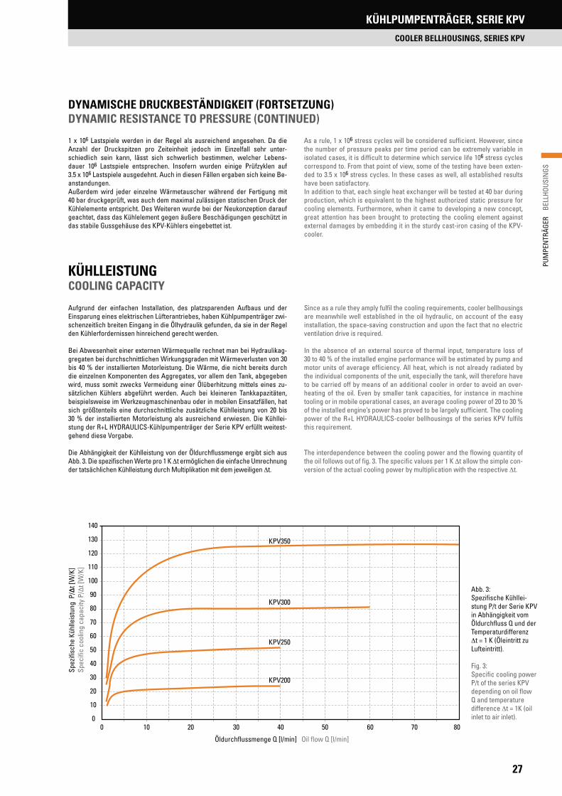
1 x 10⁶ Lastspiele werden in der Regel als ausreichend angesehen. Da die Anzahl der Druckspitzen pro Zeiteinheit jedoch im Einzelfall sehr unter-schiedlich sein kann, lässt sich schwerlich bestimmen, welcher Lebens-dauer 106 Lastspiele entsprechen. Insofern wurden einige Prüfzyklen auf 3.5 x 10⁶ Lastspiele ausgedehnt. Auch in diesen Fällen ergaben sich keine Be-anstandungen.Außerdem wird jeder einzelne Wärmetauscher während der Fertigung mit 40 bar druckgeprüft, was auch dem maximal zulässigen statischen Druck der Kühlelemente entspricht. Des Weiteren wurde bei der Neukonzeption darauf geachtet, dass das Kühlelement gegen äußere Beschädigungen geschützt in das stabile Gussgehäuse des KPV-Kühlers eingebettet ist.
As a rule, 1 x 10⁶ stress cycles will be considered sufficient. However, since the number of pressure peaks per time period can be extremely variable in isolated cases, it is difficult to determine which service life 106 stress cycles correspond to. From that point of view, some of the testing have been exten-ded to 3.5 x 10⁶ stress cycles. In these cases as well, all established results have been satisfactory.In addition to that, each single heat exchanger will be tested at 40 bar during production, which is equivalent to the highest authorized static pressure for cooling elements. Furthermore, when it came to developing a new concept, great attention has been brought to protecting the cooling element against external damages by embedding it in the sturdy cast-iron casing of the KPV-cooler.
Abb. 3: Spezifische Kühllei-stung P/t der Serie KPV in Abhängigkeit vom Öldurchfluss Q und der Temperaturdifferenz
t = 1 K (Öleintritt zu Lufteintritt).
Fig. 3:Specific cooling power P/t of the series KPV depending on oil flow Q and temperature difference t = 1K (oil inlet to air inlet).
DYNAMISCHE DRUCKBESTÄNDIGKEIT (FORTSETZUNG)DYNAMIC RESISTANCE TO PRESSURE (CONTINUED)
Aufgrund der einfachen Installation, des platzsparenden Aufbaus und der Einsparung eines elektrischen Lüfterantriebes, haben Kühlpumpenträger zwi-schenzeitlich breiten Eingang in die Ölhydraulik gefunden, da sie in der Regel den Kühlerfordernissen hinreichend gerecht werden.
Bei Abwesenheit einer externen Wärmequelle rechnet man bei Hydraulikag-gregaten bei durchschnittlichen Wirkungsgraden mit Wärmeverlusten von 30 bis 40 % der installierten Motorleistung. Die Wärme, die nicht bereits durch die einzelnen Komponenten des Aggregates, vor allem den Tank, abgegeben wird, muss somit zwecks Vermeidung einer Ölüberhitzung mittels eines zu-sätzlichen Kühlers abgeführt werden. Auch bei kleineren Tankkapazitäten, beispielsweise im Werkzeugmaschinenbau oder in mobilen Einsatzfällen, hat sich größtenteils eine durchschnittliche zusätzliche Kühlleistung von 20 bis 30 % der installierten Motorleistung als ausreichend erwiesen. Die Kühllei-stung der R+L HYDRAULICS-Kühlpumpenträger der Serie KPV erfüllt weitest-gehend diese Vorgabe.
Die Abhängigkeit der Kühlleistung von der Öldurchflussmenge ergibt sich aus Abb. 3. Die spezifischen Werte pro 1 K t ermöglichen die einfache Umrechnung der tatsächlichen Kühlleistung durch Multiplikation mit dem jeweiligen t.
KÜHLLEISTUNG COOLING CAPACITY
Since as a rule they amply fulfil the cooling requirements, cooler bellhousings are meanwhile well established in the oil hydraulic, on account of the easy installation, the space-saving construction and upon the fact that no electric ventilation drive is required.
In the absence of an external source of thermal input, temperature loss of 30 to 40 % of the installed engine performance will be estimated by pump and motor units of average efficiency. All heat, which is not already radiated by the individual components of the unit, especially the tank, will therefore have to be carried off by means of an additional cooler in order to avoid an over-heating of the oil. Even by smaller tank capacities, for instance in machine tooling or in mobile operational cases, an average cooling power of 20 to 30 % of the installed engine’s power has proved to be largely sufficient. The cooling power of the R+L HYDRAULICS-cooler bellhousings of the series KPV fulfils this requirement.
The interdependence between the cooling power and the flowing quantity of the oil follows out of fig. 3. The specific values per 1 K t allow the simple con-version of the actual cooling power by multiplication with the respective t.
0
10
20
30
40
50
60
70
80
90
100
110
120
130
140
Öldurchflussmenge Q [l/min] Oil flow Q [l/min]
KPV350
KPV300
KPV250
KPV200
Spez
ifisc
he K
ühlle
istu
ng P
/Δt [
W/K
]Sp
ecifi
c co
olin
g ca
paci
ty P
/Δt [
W/K
]
0 10 20 30 40 50 60 70 80

28
PUM
PEN
TRÄG
ER
BEL
LHOU
SIN
GSKÜHLPUMPENTRÄGER, SERIE KPV
COOLER BELLHOUSINGS, SERIES KPV
AUSTAUSCHBARKEIT NACH VDMA 24 561INTERCHANGEABILITY ACC. TO VDMA 24 561
Eine weitere Vorgabe für die Konzeption der innovativen R+L HYDRAULICS-Serie KPV war die volle Austauschbarkeit der Einbaumaße nach VDMA 24 561; und zwar nicht nur nach der Einbaulänge, sondern auch nach der Befesti-gungsposition der Fußverschraubung.
Dieses erlaubt nicht nur die Beibehaltung des gesamten Aufbaus inklusive Verrohrung im Falle von nachträglich erforderlichem Kühlereinsatz. Es erlaubt auch den Projekteuren von hydraulischen Anlagen, sich zu jedem späteren Zeitpunkt für das Erfordernis einer Kühlung mit und ohne Geräuschdämpfung zu entscheiden (siehe Abb. 2, Seite 26).
Der R+L HYDRAULICS-Kühlpumpenträger Serie KPV lässt sich sowohl in Hori-zontalbauweise IMB 35 als auch IMB 5 einbauen, dieses wiederum sowohl mit vertikalem als auch seitlichem Kühlluftaustritt. Ebenso ist der KPV in vertikaler IMV1-Bauweise montierbar.
A further guideline in the conception of the innovative R+L HYDRAULICS-series KPV was the full interchangeability of the mounting dimension acc. to VDMA 24 561 and that, not only according to the fitting length, but also accor-ding to the fastening position of the foot brackets.
This does not only make it possible to keep the complete installation, hydrau-lic piping inclusive, should the use of a cooler become necessary at a later stage. It also allows someone planning hydraulic installations, to decide on the requirements for a cooling with and without noise damper at a later point (see fig. 2, page 26).
The cooler bellhousing series KPV can be mounted horizontally IMB 35-ver-sion and IMB 5-version, and with vertical as well as with lateral cooling air discharge. But the KPV can just as well be mounted vertically – IMV1-version.
Abb. 4 Fig. 4
Abb.5: Durchflusswiderstand des Kühlelements bei einer Ölviskosität von 32 cSt.Fig. 5: Pressure drop of cooler matrix at the oil viscosity of 32 cSt.
Korrekturfaktor k für p-Werte in Abhängigkeit von anderen Viskositäten in cStCorrection factor for the p-values depending on other viscosity in cSt
kSt 15.00 22.00 32 46.00 68.00 100.00 150.0 220.0 460.0
k 0.64 0.73 1 1.28 1.62 2.65 3.9 6.9 17.1
KPV200
KPV250KPV300
KPV350
Öldurchflussmenge Q [l/min] Oil flow Q [l/min]
Durc
hflu
ssw
ider
stan
d Δ
p [b
ar]
Pres
sure
dro
p Δ
p [b
ar]
3,0
2,5
2,0
1,5
1,0
0,5
0,00 10 20 30 40 50 60 70 80

29
PUM
PEN
TRÄG
ER
BEL
LHOU
SIN
GS
KÜHLPUMPENTRÄGER, SERIE KPV
COOLER BELLHOUSINGS, SERIES KPV
ABMESSUNGENDIMENSIONS
Seitlicher Kühlluftaustritt möglich (Kühlpumpenträger um 90° gedreht) Lateral cooling air discharge possible (Cooler bellhousing rotated 90°)
Typ Type
Fußflansch PTFS Footbracket PTFS
Fußflansch PTFL Footbracket PTFL
A0[mm]
A1[mm]
B0[mm]
B1[mm]
B2[mm]
H0[mm]
A0[mm]
A1[mm]
B0[mm]
B1[mm]
B2[mm]
H0[mm]
KPV200 – – – – – – 210 180 90 20 60 112KPV250 250 215 230 125.0 60.0 155 250 220 110 40 60 132KPV300 300 265 270 149.5 75.5 185 290 260 120 40 80 160KPV350 350 300 305 175.0 90.0 235 – – – – – –
TypType
E-Motor BGFrame size
LeistungPower
WelleShaft
AbmessungenDimensions
[mm]
P [kW] D x l L0 L1 A2 A4 A5 A6 B3 H1 H2 D1 D2 D3 D4 D5 M0 G0
KPV20080
0.5519 x 24
100
88.0 123.0 204 157.0 262.0 70 176.4 144.9 200 130 165 145 11 10 G½0.75 110118
90 S+L 1.10 24 x 50 1241.50 128
KPV250
100 L2.20
28 x 60
120
108.3 144.5 267 183.0 313.0 102 193.0 168.0 250 180 215 190 14 12 G¾3.00 124
128
112 M 4.00135148175
KPV300 132 S+M
5.50
38 x 80
144
127.0 168.5 267 207.0 357.0 126 229.0 204.0 300 230 265 234 14 12 G¾7.50
150155168196
KPV350160 M+L 11.00 42 x 110 188
161.0 201.0 319 243.5 418.5 156 246.0 221.0 350 250 300 260 18 16 G¾15.00 204
180 M+L 18.50 48 x 110 22822.00 256
AA1A0
A6A4
A2
G0
A
H1H2
KühllufteintrittCooling air entry
PTFS
0H
B2B0
B1
LuftaustrittAir discharge
PTFL
D4
D3M0
B3
0H
L0L1
B2B0
B1
D2D1
PTFS
GeräuschdämpfungNoise damper
A5
D5
PTFS
FUSSFLANSCH OPTIONAL FOOTBRACKET OPTIONAL

30
PUM
PEN
TRÄG
ER
BEL
LHOU
SIN
GSPUMPENTRÄGERFÜSSE
FOOTBRACKETS
TypType
Für PumpenträgerFor bellhousing
AbmessungenDimensions
[mm]
GewichtWeight
[kg]B B1 L L1 L2 L3 L7 L8 H H1 H2 H4 R R1 S n d d1
GGG-PTFS 200 RV200/…/… 200 165 185 150 68 8 100 50 138 125 120 15 82.5 72.50 12
5
11.5 11 3.523GGG-PTFS 250 RV250/…/… 250 215 230 185 82
10125 60 165 155 150 15 107.5 95.25 17
14.0 145.291
GGG-PTFS 300 RV300/…/… 300 265 270 225 98 150 75 195 185 185 18 132.5 117.2520
9.117GGG-PTFS 350 RV350/…/… 350 300 305 265 110
12
175 90 252 235 232 22 150.0 130.50
18.0 18
17.155GGG-PTFS 400 RV400/…/… 400 350 350 300 125 200 100 275 260 240 22 175.0 150.50 22 21.585GGG-PTFS 450 RV450/…/… 450 400 385 335 133 225 110 310 295 280 22 200.0 176.00
259
27.362GGG-PTFS 550 RV550/…/… 550 500 465 415 165 275 140 370 350 318 25 250.0 226.00 42.609GGG-PTFS 660 RV660/…/… 660 600 555 495 195 18 330 165 405 380 348 30 300.0 276.00 30 20.0 22 60.398
Die volle Belastbarkeit wird nur erreicht, wenn alle vorhandenen Befestigungsbohrungen verschraubt werden!The full load capacity is reached, only if all mounting holes are being used!
PUMPENTRÄGERFÜSSE GGG-40FOOTBRACKETS GGG-40
PUMPENTRÄGERFÜSSE GGG-PTFSFOOTBRACKETS GGG-PTFS
Pumpenträgerfüße aus Sphäroguss GGG-40 sind speziell für folgende Anwendungen entwickelt worden:
- Schwerlastanwendungen- Mobilhydraulik- Bergbau, Offshore- Servomotorische Antriebe
Werkstoff: EN-GJS-400-15B = 200 – 660 mmAb Lager verfügbarAndere Größen auf AnfrageMontageanleitung beachten
nx Ø d
B
Footbrackets made of ductile iron GGG-40 are especially developed for the following applications:
- Heavy duty applications- Mobile hydraulic- Mining, Offshore- Servo motorical drives
Material: EN-GJS-400-15B = 200 – 660 mmAvailable from stockOther sizes on requestPlease consider the installation manual
Motorseite/Motor sided1
L3L2
L8L7
L1 L
Pumpenseite/Pump side
B1
S
31
PUM
PEN
TRÄG
ER
BEL
LHOU
SIN
GS
PUMPENTRÄGERFÜSSE
FOOTBRACKETS
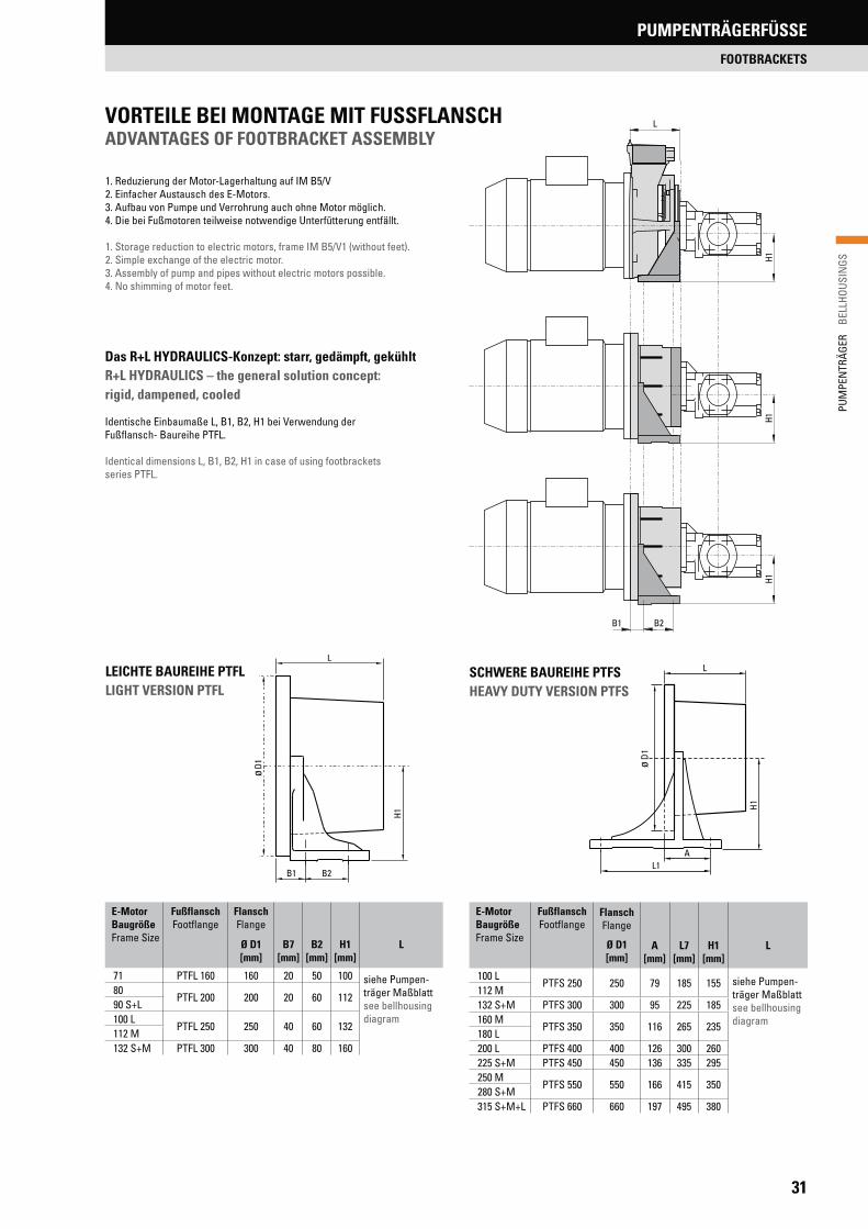
1. Reduzierung der Motor-Lagerhaltung auf IM B5/V2. Einfacher Austausch des E-Motors.3. Aufbau von Pumpe und Verrohrung auch ohne Motor möglich.4. Die bei Fußmotoren teilweise notwendige Unterfütterung entfällt.
1. Storage reduction to electric motors, frame IM B5/V1 (without feet).2. Simple exchange of the electric motor.3. Assembly of pump and pipes without electric motors possible.4. No shimming of motor feet.
Das R+L HYDRAULICS-Konzept: starr, gedämpft, gekühltR+L HYDRAULICS – the general solution concept: rigid, dampened, cooled
Identische Einbaumaße L, B1, B2, H1 bei Verwendung der Fußflansch- Baureihe PTFL.
Identical dimensions L, B1, B2, H1 in case of using footbracketsseries PTFL.
LEICHTE BAUREIHE PTFL LIGHT VERSION PTFL
SCHWERE BAUREIHE PTFSHEAVY DUTY VERSION PTFS
E-Motor BaugrößeFrame Size
FußflanschFootflange
Flansch Flange
B7[mm]
B2[mm]
H1[mm]
LØ D1[mm]
71 PTFL 160 160 20 50 100 siehe Pumpen-träger Maßblattsee bellhousing diagram
80PTFL 200 200 20 60 112
90 S+L100 L
PTFL 250 250 40 60 132112 M 132 S+M PTFL 300 300 40 80 160
E-Motor BaugrößeFrame Size
FußflanschFootflange
Flansch Flange
A[mm]
L7[mm]
H1[mm]
LØ D1[mm]
100 LPTFS 250 250 79 185 155 siehe Pumpen-
träger Maßblattsee bellhousing diagram
112 M132 S+M PTFS 300 300 95 225 185160 M
PTFS 350 350 116 265 235180 L200 L PTFS 400 400 126 300 260225 S+M PTFS 450 450 136 335 295250 M
PTFS 550 550 166 415 350280 S+M315 S+M+L PTFS 660 660 197 495 380
1H1H
B2B1
L
1H
1H
D1ø
L
B1 B2
1H
1D
ø
L
L1A
VORTEILE BEI MONTAGE MIT FUSSFLANSCHADVANTAGES OF FOOTBRACKET ASSEMBLY

32
PUM
PEN
TRÄG
ER
BEL
LHOU
SIN
GSPUMPENTRÄGERFÜSSE
FOOTBRACKETS
PTFL LEICHTE BAUREIHE PTFL LIGHT VERSION
PTFS SCHWERE BAUREIHEPTFS HEAVY DUTY VERSION
Ø d
B
2H
1H H
R1
R
HH2H1
H3
H4
B
R1RB3
Ø d
PTFS 800 auf Anfrage. Bitte beachten Sie unsere Montageanleitung. Der Pumpenträger muss mit sämtlichen Befestigungsbohrungen des Fußflansches verschraubt werden, um die volle Belastbarkeit des PTFL/PTFS zu gewährleisten!
PTFS 800 on request. Please note our assembly instruction. The bellhousing must be assembled with all mounting holes of the foot bracket, to ensure the maximum loading capacity of the PTFL/PTFS!
Typ Type
AbmessungenDimensions
[mm]
B B1 B2 B3 B4 L L1 L2 L3 L4 L5 L6 H H1 H2 H3 H4 R R1 S d d1 L L8
PTFL 160 160 140
– – –
80 50 15 7
– – –
108 100 10
– –
65.0 55.00 12 9 9
– –PTFL 200 210 180 90 60 15 4 122 112 12 82.5 72.50 14 11 11PTFL 250 250 220 110 60 25 21 145 132 15 107.5 95.00 19
14 14PTFL 300 290 260 120 80 24 20 172 160 20 132.5 117.00 18PTFS 250 250 215 193 250 162 260 185
–
10 147.5 67.5 110 167 155 155 120 15 107.5 95.15 15 15 60PTFS 300 300 265 243 300 207 270 225 10 172.0 80.0 130 197 185 185 145 18 132.5 117.25 18 20 75PTFS 350 350 300 260 350 210 305 265 12 195.0 92.0 150 255 235 235 184 18 150.0 130.00 18
18 18
25 90PTFS 400 400 350 320 400 260 350 300 12 225.0 105.0
–
277 260 232 220 20 175.0 151.00 20
–
100PTFS 450 450 400 364 450 317 385 335 12 250.0 113.0 312 295 272 238 20 200.0 176.00 22 110PTFS 550 550 500 454 550 401 465 415 12 300.0 140.0 365 350 335 285 25 250.0 226.00 25 140PTFS 660 660 600 550 660 486 555 495 18 360.0 165.0 400 380 360 308 30 300.0 276.00 30 22 22 165
PUMPENTRÄGERFÜSSE BAUREIHE PTFL / PTFS
FOOTBRACKETS SERIES PTFL / PTFSnach VDMA 24 561, für Motorbauform IM B5 acc. to VDMA 24 561 for bellhousings, motor type IM B5
B1
S
L2
L3 L1 L
Ø d1 B1
B2
B4L3
S
L8L6 L4
L 1 L
L5
Ø d1

33
PUM
PEN
TRÄG
ER
BEL
LHOU
SIN
GS
DÄMPFUNGSRINGE
DAMPING RINGS
TYPENBEZEICHNUNGMODEL TYPE
• Für vertikale und horizontale Montage• Kostengünstige Schallreduzierung durch Entkoppelung• Mineralölbeständigkeit durch NBR-Gummimischung• Anvulkanisierte Dichtlippe, keine zusätzliche Dichtung erforderlich
DR - V1 / B5 - 300 / VS
ABMESSUNGEN DIMENSIONS
Stan
dard
ausf
ühru
ngSt
anda
rd v
ersi
on
200250300 300
VS-A
usfü
hrun
gVS
-Des
ign350 350
400 400450 450550 550660 660
AusführungDesign
–StandardausführungStandard version
VSVS-AusführungVS-Design
2D D
D1
A
A
G
L
I
d
A
A
d1
L
Ausführung DR.../VS mit Senkbohrungen zur Vereinfachung der IM V1-Montage
Design DR.../VS with counterbore holes for easy vertically IM V1 mounting
Schnitt A - ADetail A - A
Schnitt A - ADetail A - A
L 2F F
L 1
PumpePump
MotorMotor
Zulässige radiale Gewichts- und Biegebelastung bei einer Betriebstemperatur von + 60 °CPermissible radial weight and bending loads with an operating temperature of + 60 °C
Fzul FPumpe+FMotor
Mbzul FMotor x L1- FPumpe x L2
TECHNISCHE DATEN TECHNICAL DATA
Dämpfungsring Typ Damping rings
IEC-Motor Baugröße IEC-Motor frame size
AbmessungenDimensions
[mm]
D D1 D2 G I L d d1
DR-V1/B5-200 80 / 90S / 90L 200 165 146 4 x M10 18 40
– –
DR-V1/B5-250 100L / 112M 250 215 1914 x M12
2245
DR-V1/B5-300 132S / 132M 300 265 235 50DR-V1/B5-350 160M / 160L / 180M / 180L 350 300 261
4 x M1660
DR-V1/B5-400 200L 400 350 301 29 50DR-V1/B5.450 225S / 225M 450 400 352
8 x M16 32 60DR-V1/B5-550 250M / 280S / 280M 550 500 452DR-V1/B5-660 315S / 315M 660 600 552 8 x M20 33 65DR-V1/B5-300/VS 132S / 132M 300 265 235 4 x M12
2250 4 x 14 4 x 20
DR-V1/B5-350/VS 160M / 160L / 180M / 180L 350 300 2614 x M16
604 x 18 4 x 26
DR- V1/B5-400/VS 200L 400 350 301 29 50DR- V1/B5-450/VS 225S / 225M 450 400 352
8 x M1632
60 8 x 18 8 x 26DR-V1/B5-550/VS 250M / 280S / 280M 550 500 452DR-V1/B5-660/VS 315S / 315M 660 600 552 8 x M20 65 8 x 22 8 x 31
DR-TypDR-Type 200 250 300 350 400 450 550 660Fzul [N] 385 755 1520 3780 5040 6800 13390 24720Mbzul [Nm] 30 65 175 740 1100 1600 4400 9000
• Vertical and horizontal mounting• Low cost noise level reducing as a result of rubber flexible separation• Resistance against mineral-oil due to NBR-rubber• Moulded ring-sealing, no additional sealing required
Fzul FPump+FMotor
Mbzul FMotor x L1- FPump x L2
DÄMPFUNGSRINGE
DAMPING RINGS

34
PUM
PEN
TRÄG
ER
BEL
LHOU
SIN
GSDÄMPFUNGSSCHIENEN
DAMPING RODS
ABMESSUNGEN DIMENSIONS
PRODUKTEIGENSCHAFTENFEATURES
• For electric motors with frame size IM B35 and footbrackets acc. VDMA 24 561
• Dimensioned for loads in case of horizontal mounting• Noise absorbing and vibration damping• Resistance against mineral-oil because of NBR-rubber
• Für Elektromotoren Bauform IM B35 und Fußflansche nach VDMA 24 561• Ausgelegt für die Gewichtsbelastung bei horizontalem Einbau• Schallreduzierend und schwingungsdämpfend• Mineralölbeständigkeit durch NBR-Gummimischung
TYPENBEZEICHNUNGMODEL TYPE
Dämpfungsschienen-TypType of damping rod
ElektromotorenElectric motors MDL/DSM
Fußflansche schwerFootbrackets heavy duty PTFSDL
Fußflansche leichtFootbrackets light PTFLDL
Nenngröße(siehe Tabelle unten)Nominal size(see table below)
P T F S D L 6 6 0
DÄMPFUNGSSCHIENEN DAMPING RODS
Dämpfungsschienen Damping rods
MotortypMotor type
L[mm]
L1[mm]
L2[mm]
L3[mm]
h[mm]
h1[mm]
h2[mm]
b[mm]
b1[mm]
b2[mm]
d[mm]
D[mm]
M1 M2
MDL 71 71196
90156
–
408 12 50
21
25 14 20
M6
–
MDL 80 80100 22
M8MDL 90S 90SMDL 90L 90L
240125
20524
MDL 100L 100L140
M10MDL 112M 112M
20MDL 132S 132S285 245 45
MDL 132M 132M 178MDL 160M 160M 340 210 300
60
15 15
70
28
35
18 26 M12MDL 160L 160L
416254
370MDL 180M 180M 241
35MDL 180L 180L 446 279 400MDL 200L 200L
496
305430
22 32 M16MDL 225S 225S 286MDL 225M 225M 311
445MDL 250M 250M 349
100 50 50 25 40 M20MDL 280S 280S580
368530
MDL 280M 280M 419MDL 315S 315S
660406
61070 150 60 75 25 40 M24MDL 315M 315M 457
MDL 315L 315L 720 508 670
TECHNISCHE DATEN TECHNICAL DATA
AUSFÜHRUNG MDL FÜR ELEKTROMOTOREN TYPE MDL FOR ELECTRIC MOTORS
35
PUM
PEN
TRÄG
ER
BEL
LHOU
SIN
GS
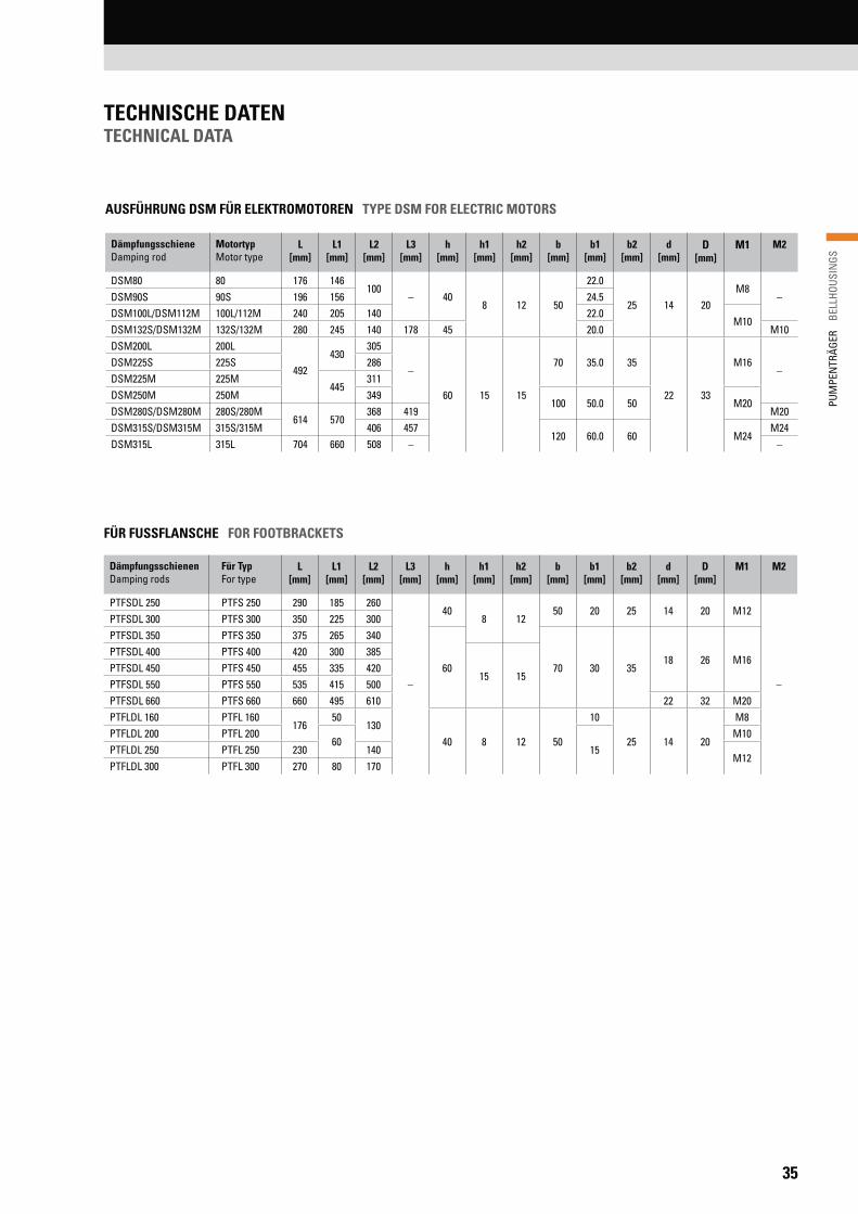
TECHNISCHE DATEN TECHNICAL DATA
Dämpfungsschiene Damping rod
MotortypMotor type
L[mm]
L1[mm]
L2[mm]
L3[mm]
h[mm]
h1[mm]
h2[mm]
b[mm]
b1[mm]
b2[mm]
d[mm]
D[mm]
M1 M2
DSM80 80 176 146100
– 408 12 50
22.0
25 14 20M8
–DSM90S 90S 196 156 24.5DSM100L/DSM112M 100L/112M 240 205 140 22.0
M10DSM132S/DSM132M 132S/132M 280 245 140 178 45 20.0 M10DSM200L 200L
492430
305
–
60 15 15
70 35.0 35
22 33
M16–
DSM225S 225S 286DSM225M 225M
445311
DSM250M 250M 349100 50.0 50 M20
DSM280S/DSM280M 280S/280M614 570
368 419 M20DSM315S/DSM315M 315S/315M 406 457
120 60.0 60 M24M24
DSM315L 315L 704 660 508 – –
Dämpfungsschienen Damping rods
Für TypFor type
L[mm]
L1[mm]
L2[mm]
L3[mm]
h[mm]
h1[mm]
h2[mm]
b[mm]
b1[mm]
b2[mm]
d[mm]
D[mm]
M1 M2
PTFSDL 250 PTFS 250 290 185 260
–
408 12
50 20 25 14 20 M12
–
PTFSDL 300 PTFS 300 350 225 300PTFSDL 350 PTFS 350 375 265 340
60 70 30 3518 26 M16
PTFSDL 400 PTFS 400 420 300 385
15 15PTFSDL 450 PTFS 450 455 335 420PTFSDL 550 PTFS 550 535 415 500PTFSDL 660 PTFS 660 660 495 610 22 32 M20PTFLDL 160 PTFL 160
17650
13040 8 12 50
10
25 14 20
M8PTFLDL 200 PTFL 200
6015
M10PTFLDL 250 PTFL 250 230 140
M12PTFLDL 300 PTFL 300 270 80 170
FÜR FUSSFLANSCHE FOR FOOTBRACKETS
AUSFÜHRUNG DSM FÜR ELEKTROMOTOREN TYPE DSM FOR ELECTRIC MOTORS

EINFÜHRUNG BEHÄLTER UND ZUBEHÖR
INTRODUCTION RESERVOIRS AND ACCESSORIES
36
Alubehälter mit StahldeckelAl-reservoir with steel lid

EINFÜHRUNG BEHÄLTER UND ZUBEHÖR
INTRODUCTION RESERVOIRS AND ACCESSORIES
37
ALUBEHÄLTER 38AL-RESERVOIRS
ZUBEHÖR 46ACCESSORIES
BEHÄLTER UND ZUBEHÖRRESERVOIRS AND ACCESSORIES
BEHÄ
LTER
RE
SERV
OIRS

38
BEHÄ
LTER
R
ESER
VOIR
SALUBEHÄLTER
AL-RESERVOIRS
ALUBEHÄLTERAL-RESERVOIRS
TECHNISCHE DATENTECHNICAL DATA
* Abhängig von Umgebungsbedingungen * Depending on ambient conditions
BehältergrößeSize of reservoir
NutzvolumenEffective volume
Spezifische KühlleistungSpecific cooling capacity
Kühlleistung*Cooling capacity*
Oberfläche mit DeckelSurface with reservoir lid
GewichtWeight
V [I] VN [I] P/ t [W/K] P [kW] t = 40 K [m2] [kg]
NG3.5 3.0 4 0.16 0.15 1.4NG6.5 6.0 9 0.36 0.25 1.7NG8 6.5 11 0.44 0.30 2.5NG12 10.0 15 0.60 0.35 2.3NG13 11.0 15 0.60 0.40 2.8NG20 17.0 18 0.72 0.50 4.3NG30 27.0 23 0.92 0.75 5.0NG44 40.0 26 1.04 1.00 7.0NG70 63.0 29 1.16 1.30 10.0NG130 123.0 52 2.10 1.93 25.0

39
BEHÄ
LTER
RE
SERV
OIRS
ALUBEHÄLTER
AL-RESERVOIRS
TYPENBEZEICHNUNG ALUBEHÄLTERMODEL TYPE AL-RESERVOIRS
NG30 SF 1
Bohrungen für AnzeigeBores for oil level gauge
ohnewithout –
mitwith SBNenngröße
Nominal size
3.5
6.5
8
12
13
20
30
44
70
130
Bohrungen für ÖlstandsanzeigeBores for oil level gauge
– ohnewithout
SF1 Ölstandsanzeige 76 mmOil level gauge 76 mm
SF2 Ölstandsanzeige 127 mmOil level gauge 127 mm
SF3 Ölstandsanzeige 254 mmOil level gauge 254 mm
KL13 Ölauge G¼"Oil eye G¼"
A18 Ölauge G¾"Oil eye G¾"
KL33 Ölauge G1"Oil eye G1"
TYPENBEZEICHNUNG BEHÄLTERDECKEL – STAHL/ALU MODEL TYPE STEEL/ALU LID
SD 30 / 200
NenngrößeNominal size
3.5
6.5
8
12
13
20
30
44
70
130
DeckelmaterialMaterial reservoir lid
StahlSteel SD
AluAlu AD
PumpenträgerbohrungBores for bellhousing
– ohnewithout
140NG6.5NG12/13
160NG6.5NG12/13NG20
200
NG12/13NG20NG30NG44
250
NG20NG30NG44NG70
300NG30NG44NG70
SB
40
BEHÄ
LTER
R
ESER
VOIR
SALUBEHÄLTER
AL-RESERVOIRS
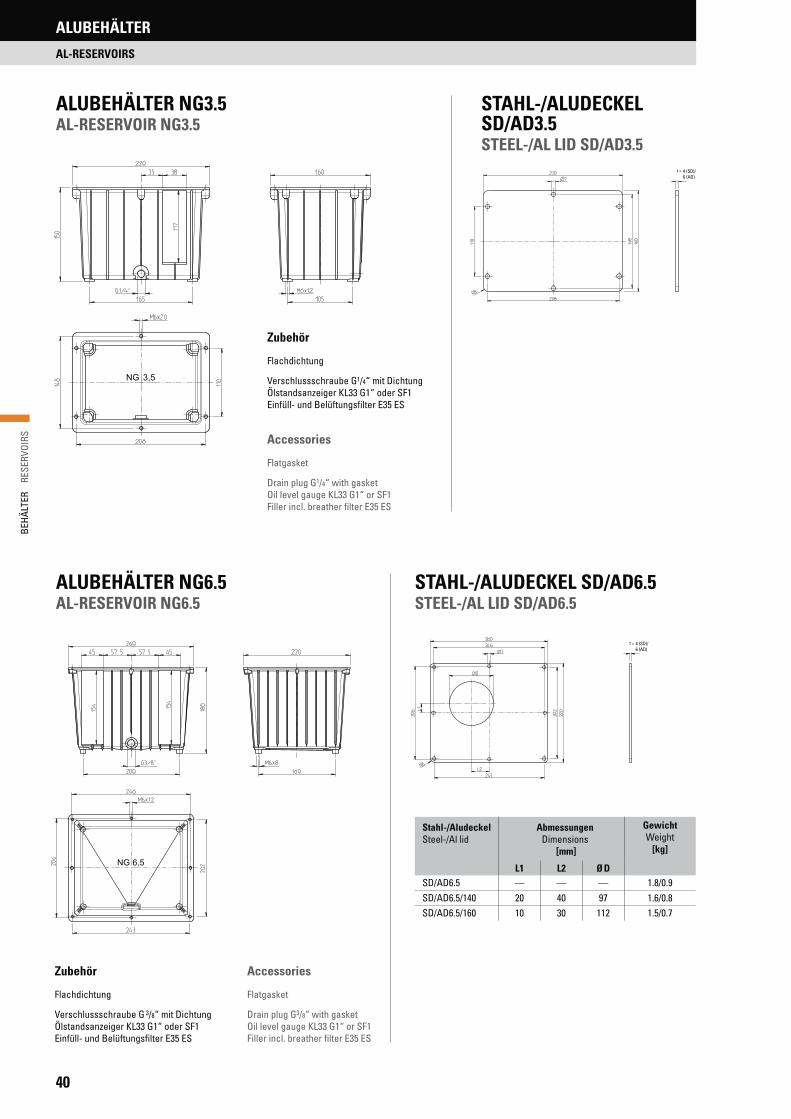
ALUBEHÄLTER NG3.5AL-RESERVOIR NG3.5
STAHL-/ALUDECKEL SD/AD3.5STEEL-/AL LID SD/AD3.5
Accessories
Flatgasket
Drain plug G1/4“ with gasket Oil level gauge KL33 G1“ or SF1Filler incl. breather filter E35 ES
Zubehör
Flachdichtung
Verschlussschraube G 3/8“ mit DichtungÖlstandsanzeiger KL33 G1“ oder SF1Einfüll- und Belüftungsfilter E35 ES
Stahl-/AludeckelSteel-/Al lid
Abmessungen Dimensions
[mm]
GewichtWeight
[kg]
L1 L2 Ø DSD/AD6.5 — — — 1.8/0.9SD/AD6.5/140 20 40 97 1.6/0.8SD/AD6.5/160 10 30 112 1.5/0.7
4 (SD)/6 (AD)
t =
Accessories
Flatgasket
Drain plug G3/8“ with gasketOil level gauge KL33 G1“ or SF1Filler incl. breather filter E35 ES
Zubehör
Flachdichtung
Verschlussschraube G1/4“ mit Dichtung Ölstandsanzeiger KL33 G1“ oder SF1Einfüll- und Belüftungsfilter E35 ES
ALUBEHÄLTER NG6.5AL-RESERVOIR NG6.5
STAHL-/ALUDECKEL SD/AD6.5STEEL-/AL LID SD/AD6.5
4 (SD)/6 (AD)
t =

41
BEHÄ
LTER
RE
SERV
OIRS
ALUBEHÄLTER
AL-RESERVOIRS
4 (SD)/6 (AD)
t =
4 (SD)/8 (AD)
t =
Zubehör
Flachdichtung
Verschlussschraube G3/8“ mit DichtungÖlstandsanzeiger KL33 G1“ Dichtung D160 NBR für Pumpenträger
Accessories
Flatgasket
Drain plug G3/8“ with gasketOil level gauge KL33 G1“ Gasket D160 NBR for bellhousing
ALUBEHÄLTER NG8AL-RESERVOIR NG8
STAHL-/ALUDECKEL SD/AD8STEEL-/AL LID SD/AD8
ALUBEHÄLTER NG12AL-RESERVOIR NG12
STAHL-/ALUDECKEL SD/AD12STEEL-/AL LID SD/AD12
Zubehör
Flachdichtung
Gussfüße 75 mm hochVerschlussschraube G3/8“ mit DichtungÖlstandsanzeiger KL33 G1“, SF1 oder SF2Einfüll- und Belüftungsfilter E35 ES
Accessories
Flatgasket
Cast feet 75 mm highDrain plug G3/8“ with gasketOil level gauge KL33 G1“, SF1 or SF2Filler incl. breather filter E35 ES
Stahl-/AludeckelSteel-/Al lid
Abmessungen Dimensions
[mm]
GewichtWeight
[kg]
L1 L2 Ø D
SD/AD12 – – – 2.4/1.6SD/AD12/140 25 60 97 2.1/1.5SD/AD12/160 25 60 112 2.0/1.4SD/AD12/200 5 40 147 1.8/1.3
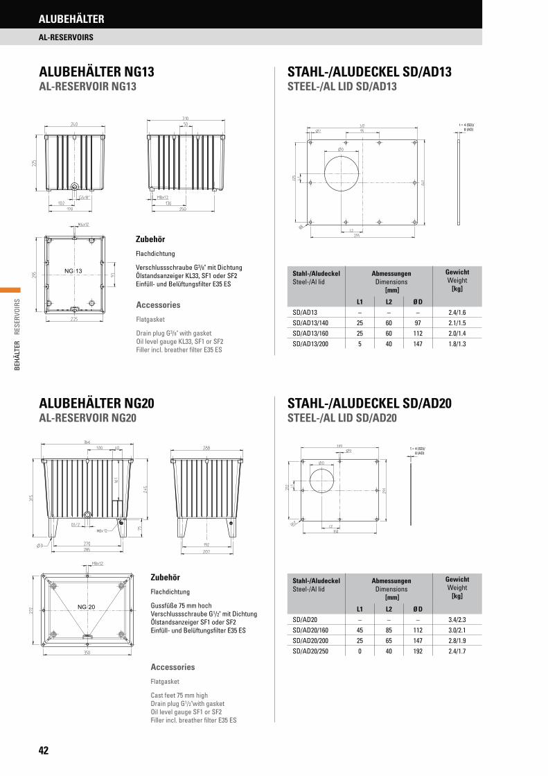
42
BEHÄ
LTER
R
ESER
VOIR
S
Zubehör
Flachdichtung
Verschlussschraube G3/8" mit DichtungÖlstandsanzeiger KL33, SF1 oder SF2Einfüll- und Belüftungsfilter E35 ES
Accessories
Flatgasket
Drain plug G3/8" with gasketOil level gauge KL33, SF1 or SF2Filler incl. breather filter E35 ES
Zubehör
Flachdichtung
Gussfüße 75 mm hochVerschlussschraube G1/2" mit DichtungÖlstandsanzeiger SF1 oder SF2Einfüll- und Belüftungsfilter E35 ES
Accessories
Flatgasket
Cast feet 75 mm highDrain plug G1/2"with gasketOil level gauge SF1 or SF2Filler incl. breather filter E35 ES
4 (SD)/8 (AD)
t =
4 (SD)/8 (AD)
t =
ALUBEHÄLTER NG13AL-RESERVOIR NG13
STAHL-/ALUDECKEL SD/AD13STEEL-/AL LID SD/AD13
ALUBEHÄLTER NG20AL-RESERVOIR NG20
STAHL-/ALUDECKEL SD/AD20STEEL-/AL LID SD/AD20
ALUBEHÄLTER
AL-RESERVOIRS
Stahl-/AludeckelSteel-/Al lid
Abmessungen Dimensions
[mm]
GewichtWeight
[kg]
L1 L2 Ø D
SD/AD13 – – – 2.4/1.6SD/AD13/140 25 60 97 2.1/1.5SD/AD13/160 25 60 112 2.0/1.4SD/AD13/200 5 40 147 1.8/1.3
Stahl-/AludeckelSteel-/Al lid
Abmessungen Dimensions
[mm]
GewichtWeight
[kg]
L1 L2 Ø D
SD/AD20 – – – 3.4/2.3SD/AD20/160 45 85 112 3.0/2.1SD/AD20/200 25 65 147 2.8/1.9SD/AD20/250 0 40 192 2.4/1.7

43
BEHÄ
LTER
RE
SERV
OIRS
ALUBEHÄLTER
AL-RESERVOIRS
ALUBEHÄLTER NG30AL-RESERVOIR NG30
STAHL-/ALUDECKEL SD/AD30STEEL-/AL LID SD/AD30
ALUBEHÄLTER NG44AL-RESERVOIR NG44
STAHL-/ALUDECKEL SD/AD44STEEL-/AL LID SD/AD44
5 (SD)/8 (AD)
t =
Zubehör ÖlauffangdichtungRundschnurdichtung NBR 6 mm
Gussfüße 150 mm hoch, Lenkrollen 150 mm hochVerschlussschraube G1/2" mit DichtungÖlstandsanzeiger SF1 oder SF2Einfüll- und Belüftungsfilter E35 ES oder EB80-10
AccessoriesOil drip-tray gasketRound section gasket NBR 6 mm
Cast feet 150 mm high, Castors 150 mm highDrain plug G1/2“ with gasketOil level gauge SF1 or SF2Filler incl. breather filter E35 ES or EB80-10
Zubehör ÖlauffangdichtungRundschnurdichtung NBR 6 mm
Gussfüße 150 mm hoch, Lenkrollen 150 mm hochVerschlussschraube G1/2" mit DichtungÖlstandsanzeiger SF1 oder SF2Einfüll- und Belüftungsfilter E35 ES oder EB80-10
AccessoriesOil drip-tray gasketRound section gasket NBR 6 mm
Cast feet 150 mm high, Castors 150 mm highDrain plug G1/2" with gasketOil level gauge SF1 or SF2Filler incl. breather filter E35 ES or EB80-10
5 (SD)/8 (AD)
t =
Stahl-/AludeckelSteel-/Al lid
Abmessungen Dimensions
[mm]
GewichtWeight
[kg]
L1 L2 Ø D
SD/AD30 – – – 6.5/3.6SD/AD30/200 50 120 147 5.9/3.2SD/AD30/250 25 95 192 5.4/2.9SD/AD30/300 0 70 236 4.8/2.6
Stahl-/AludeckelSteel-/Al lid
Abmessungen Dimensions
[mm]
GewichtWeight
[kg]
L1 L2 Ø D
SD/AD44 – – – 8.7/4.7SD/AD44/200 90 140 147 8.0/4.4SD/AD44/250 65 115 192 7.6/4.1SD/AD44/300 40 90 236 7.0/3.8

44
BEHÄ
LTER
R
ESER
VOIR
SALUBEHÄLTER
AL-RESERVOIRS
5 (SD)/8 (AD)
t =
Zubehör
ÖlauffangdichtungRundschnurdichtung NBR 6 mm
Gussfüße 150 mm hoch, Lenkrollen 150 mm hochVerschlussschraube G1/2" mit DichtungÖlstandsanzeiger SF1, SF2 oder SF3Einfüll- und Belüftungsfilter E35 ES oder EB80-10
Accessories
Oil drip-tray gasketRound section gasket NBR 6 mm
Cast feet 150 mm high, Castors 150 mm highDrain plug G1/2" with gasketOil level gauge SF1, SF2 or SF3Filler incl. breather filter E35 ES or EB80-10
L
M8x18
285
536
150
597
Ø 11
Q
744
277.5735
G1/2"
397437
1039
6
285
597109
78
M10x15
557
757183
78
166.
5
583
575
12 x Ø 9
600
575
583
744
277.5735760
166.
5
R216 (SD)/10 (AD)
t =
ALUBEHÄLTER NG70AL-RESERVOIR NG70
STAHL-/ALUDECKEL SD/AD70STEEL-/AL LID SD/AD70
ALUBEHÄLTER NG130AL-RESERVOIR NG130
STAHL-/ALUDECKEL SD/AD130STEEL-/AL LID SD/AD130
Zubehör Rundschnurdichtung NBR 6 mmGussfüße 150 mm hoch, Lenkrollen 150 mm hochVerschlussschraube G1/2" mit DichtungÖlstandsanzeiger SF1, SF2 oder SF3Einfüll- und Belüftungsfilter E35 ES oder EB80-10Schwallbleche längs (L) und quer (Q) einsteckbarÖlauffangwanne auf Anfrage
AccessoriesRound section gasket NBR 6 mmCast feet 150 mm highCastors 150 mm highDrain plug G1/2" with gasketOil level gauge SF1, SF2 or SF3Filler incl. breather filter E35 ES or EB80-10Baffles along (L) and across (Q) plugableOil sump on request
Stahl-/AludeckelSteel-/Al lid
Abmessungen Dimensions
[mm]
GewichtWeight
[kg]
L1 L2 Ø DSD/AD70 – – – 11.4/6.2SD/AD70/250 80 150 192 10.2/5.6SD/AD70/300 55 125 236 9.6/5.3
Stahl-/AludeckelSteel-/Al lid
Abmessungen Dimensions
[mm]
GewichtWeight
[kg]
L1 L2 Ø DSD/AD130 – – – 21.4/7.3SD/AD130/250
125150 192 20.0/6.8
SD/AD130/300 125 236 19.4/6.6

45
BEHÄ
LTER
RE
SERV
OIRS
ALUBEHÄLTER
AL-RESERVOIRS
ÖlwanneOil sump
Für BehälterFor reservoir
VolumenVolume
[l]
Abmessungen Dimensions
[mm]
L1 L2 L3 B1 B2 B3 B4 H1 H2 t1 t2 z Ø D
BWA30 NG30 33 550 326.0 300 40075
176.0 150160 153
3 5
812BWA44 NG44 45 600 341.0
–500 241.0
– 4BWA70 NG70 64 730 422.5 580 282.5BWA130 NG130 144 920 557.0 770 70 397.0 210 200 18
Bitte beachten:• Öldicht geschweißt, gemäß WHG19.• WHG19-Zertifikat & Stempel gegen Aufpreis auf Anfrage!• Pulver beschichtet RAL 9006 – Weißaluminium
Please note:• Oil-tight welded, acc. to WHG19• WHG19-certificate & stamp against extra charge on request!• powder coated RAL 9006 – white aluminium
Art. Nr.:Art. No.:
Behälter-GrößeSize of reservoir
Abmessungen Dimensions
[mm]
Theoretisches ÖlvolumenTheoretic oil volume
[l]
A B CDI0173 NG30 349 499
232.1
DI0172 NG44 432 533 2.6DI0170 NG70 482 623 3.5
ÖLAUFFANGDICHTUNG FÜR BEHÄLTERGRÖSSEN NG30, NG44 UND NG70OIL DRIP-TRAY GASKET FOR RESERVOIR SIZES NG30, NG44 AND NG70
1 2 3
Vorteile: • Lärmreduzierung• einfache Montage, problemlose Handhabung• keine zusätzliche Rundschnurdichtung erforderlich• Beständigkeit gegen alle gängigen Mineralöle• ab Lager verfügbar
H1
H2 t2
B1
t1
B3
B4
L2L1
B2
L3
Deutsches Gebrauchsmuster erteilt: Nr. 20 2006 001 703.8German utility patent granted: No 20 2006 001 703.8
Advantages:• Noise reduction• Simple assembly, smooth application• No additional round section gasket necessary• Resistance against all common mineral oils• Available from stock
ÖLWANNENOIL SUMPS

46
BEHÄ
LTER
R
ESER
VOIR
S
REINIGUNGSDECKEL IN ALUMINIUMGUSSLIGHT ALUMINIUM CLEANING COVERS
188
3D
Ø2
DØØ
D
Ø 12
1 D
Ø
1D
Ø
Ø 12Ø 121
DØ
Feld für Schriftzug 260 x 125 mmArea for logo 260 x 125 mm
Feld für Schriftzug 260 x 125 mmArea for logo 260 x 125 mm
*Reinigungsdeckel nach DIN 24 339 *Cleaning covers acc. to DIN 24 339
RD250-4 RD350-4/RD350-6 RD475-6
Reinigungsdeckel-TypType of cleaning cover
AbmessungenDimensions
[mm]
Profildichtung 16 x 18Profile gasket 16 x 18
Ø D Ø D1 Ø D2 Ø D3 Perbunan Viton
RD250-4 250 224 167 159 D168 NBR D168 FPMRD350-V 324-4*
350 324 267 261 D268 NBR D268 FPMRD350-V 324-6*
RD475-V 449-6* 475 449 392 386 D393 NBR D393 FPM
Schraubenanzugsmoment max. 10 NmTightening torque of screws max. 10 Nm
Schraubenanzugsmoment max. 10 NmTightening torque of screws max. 10 Nm
Schraubenanzugsmoment max. 10 NmTightening torque of screws max. 10 Nm
Feld für Schriftzug 170 x 80 mmArea for logo 170 x 80 mm
ZUBEHÖR
ACCESSORIES
REINIGUNGSDECKEL MIT IHREM FIRMENLOGOAUF ALUMINIUM-DIBOND-SCHILD UND HOCHWERTIGEM 4C-FARBDRUCK!
Erhältlich für Reinigungsdeckel der Größen RD350 + RD475
• Erhöht die Erkennbarkeit Ihres Firmenlogos auf Hydraulikaggregaten• Keine Investition in Alu-Schriftstempel nötig• Auch in Kleinstmengen zu günstigen Preisen erhältlich
Ihre individuellen Nettopreise erhalten Sie gerne auf Anfrage.Wir freuen uns auf Ihren Anruf!
CLEANING COVER WITH YOUR COMPANY LOGOON ALUMINIUM-DIBOND-PLATE AND HIGH-QUALITY 4C-COLOUR PRINT!
• Increases the visibility of your company logo on hydraulic untis• Also available in small quantities at an attracive price• No investment for a cast name plate needed
Your individual net price will be gladly provided upon request.We look forward to your call!
Fits for cleaning cover sizes RD350 + RD475

47
BEHÄ
LTER
RE
SERV
OIRS
ZUBEHÖR
ACCESSORIES
1 D
Ø
2D
ØØ D
Ø12 188
630
Feld für Schriftzug 270 x 130 mm*Area for logo 270 x 130 mm*
RD235 Feld für Schriftzug 115 x 30 mmRD235 Area for logo 115 x 30 mm
RD345 Feld für Schriftzug 220 x 58 mmRD345 Area for logo 220 x 58 mm
BehälterwandReservoir wall
DeckelCover
SchraubeScrew
DichtungGasket
KreuzCross
O-RingO-Ring
*RD560-6 (6-Loch)*RD560-6 (6-holes)
RD720-12 (12-Loch)RD720-12 (12-holes)
RD235 / RD345
Schraubenanzugsmoment max. 40 NmTightening torque of screws max. 40 Nm
Reinigungsdeckel-TypType of cleaning cover
AbmessungenDimensions
[mm]
DichtungGasket
SchraubeScrew
O-RingO-Ring
Ø D Ø D1 Ø D2 Perbunan VitonRD235 235 200 202 22 x 16 x 1.5 M16 x 55 214 x 5 NBR 214 x 5 FPMRD345 345 306 308 28.7 x 21.5 x 2.5 M20 x 65 319 x 8.4 NBR 315 x 10 FPM
Reinigungsdeckel-TypType of cleaning cover
AbmessungenDimensions
[mm]
Profildichtung 16 x 18Profile gasket 16 x 18
Ø D Ø D1 Ø D2 Ø D3 Perbunan Viton
RD560 560 530 470 460 D471 NBR –RD620 620 580 520 512 D520 NBR –RD720 720 680 620 608 D620 NBR –
Ronde nicht im Lieferumfang enthaltenCircular blank is not included in delivery
Schraubenanzugsmoment max. 10 NmTightening torque of screws max. 10 Nm
RD620-8 (8-Loch)RD620-8 (8-holes)

48
BEHÄ
LTER
R
ESER
VOIR
SZUBEHÖR
ACCESSORIES
B = Rohr ØD = Bohrungs Ø im DeckelB = Pipe dia.D = Bore dia. in lid
Technische DatenTechnical data
Allgemeine Temperaturgrenzen:a) Dauertemperatur = 90 – 95 °Cb) kurzfristige Temperaturspitzen = max. 110 °C
Materialeigenschaften des ElastomersGute Beständigkeit gegen Mineralöl, Benzin, Propan, Fette auf Mineralölbasis, Diesel, leichtes Heizöl, pflanzliche und tierische Fette.Bedingte Beständigkeit gegen Kraftstoffe mit hohem Aromatengehalt (Superkraftstoff). Schwache Beständigkeit gegen aromatische Kohlenwasserstoffe (z. B. Benzol), chlorierte Kohlenwasserstoffe (z. B. Trichlorethylen), Ester und polare Lösungsmittel.
General temperature limits:a) Continuous temperature = 90 – 95 °Cb) Peak temperature = max. 110 °C
Material properties of the elastomerGood resistance against mineral oil, petrol, propane, grease based on mineral oil, diesel, light fuel oil, vegetable and animal fat.Conditional resistance against high octane grade fuels. Low resis-tance against aromatic hydrocarbons (e.g. benzene), chlorinated hydrocarbons (e.g. trichloroethylene), ester and polar solvents.
Ab Lager verfügbar! On stock available!
Artikel Nr.Ident No.
Rohr ø Pipe ø [mm]
A
[mm]
B
[mm]
C
[mm]
D
[mm]
E
[mm]
F
[mm]
G
[mm]
H
[mm]
BZUB0123 8 12.0 8 6.4 14.0 20
25
3
12
BZUB0124 10 14.0 10 8.418.0 24BZUB0125 12 16.0 12 10.4
4BZUB0128 16 20.0 16 14.424.0 32BZUB0129 18 22.0 18 16.4
BZUB0130 20 24.0 20 18.430.0 40
5
BZUB0132 22 26.0 22 20.4BZUB0133 25 29.0 25 23.4
35.0 45BZUB0135 28 32.0 28 26.4BZUB0136 30 34.0 30 28.4 40.0 50BZUB0138 35 39.0 35 33.4
48.0 54BZUB0139 38 42.0 38 36.4
DECKELDURCHFÜHRUNG FÜR HYDRAULIK-ROHREBUSHINGS FOR HYDRAULIC PIPES THROUGH LIDS
Deckeldurchführungen werden bei Hydraulik-Aggregaten zur öldichten Fixierung der genormten Hydraulik-Rohre in Tankdeckeln eingesetzt. Vorteil: Ein öldichter und staub-dichter Sitz der Rohre im Deckel. Aufgrund einer speziellen Elastomermischung wird eine extreme Lärmminderung der Körperschallübertragung von der Ölsäule auf den Tankdeckel erreicht. Die Montage erfolgt durch einfaches Einstecken der Deckeldurchführung in die Tank-deckelbohrung. Das eingefettete Rohr wird anschließend in die Deckeldurchführung eingesteckt.
Bushings for lids that provide leak free sealing of standardised hydraulic pipes. Ad-vantage: Oil-tight and dust-proof sealing of the pipes. Excellent noise reduction is achieved from the elastomer compound bushings that insulate the oil column from the lid. Simple assembly by inserting the bushing into the bore hole of the lid and then in-stalling the lubricated pipe into the bushing.
Artikel Nr.Ident No.
Rohr ø Pipe ø [inch]
A
[mm]
B
[inch]
C
[mm]
D
[mm]
E
[mm]
F
[mm]
G
[mm]
H
[mm]
BZUB0126 ¼‘‘ 17.5 ¼‘‘ 11.9 24.0 32
25
4
12
BZUB0131 ½‘‘ 25.0 ½‘‘ 19.4 30.0 40
5BZUB0134 ¾‘‘ 30.0 ¾‘‘ 24.4 35.0 45BZUB0137 1‘‘ 37.0 1‘‘ 31.4 40.0 50BZUB0140 1¼‘‘ 46.0 1¼‘‘ 40.4 52.0 62BZUB0141 1½‘‘ 52.0 1 ½‘‘ 46.4 58.0 68
6BZUB0142 2‘‘ 64.0 2‘‘ 58.4 72.0 80BZUB0143 2 ½‘‘ 80.0 2 ½‘‘ 75.4 88.5 110BZUB0144 ¼‘‘ 10.5 ¼‘‘ 5.0 12.0 18
3BZUB0145 3/8‘‘ 13.5 3/8‘‘ 8.0 16.0 23BZUB0146 ½‘‘ 17.0 ½‘‘ 11.0
24.0 32BZUB0147 ¾‘‘ 23.0 ¾‘‘ 17.4 4BZUB0148 1¼‘‘ 36.0 1¼‘‘ 30.2 40.0 50 5

49
BEHÄ
LTER
RE
SERV
OIRS
ZUBEHÖR
ACCESSORIES
SF1 – SF3
KL13, KL33, A18
B
D
C
E
F
G
*A18 mit Mutter *A18 with nut
TypType
Abmessungen Dimensions
[mm]
A B C D E F G
SF1 / SF1 Th 76 32 108
34 45.0 28.0 M12SF2 / SF2 Th 127 76 159
SF3 / SF3 Th 254 203 286
KL13 – Ø 9 Ø 20 SW17 16.0 7.0 G 1/4"
A18* – Ø 18 Ø 35 SW32 18.5 8.5 G 3/4"
KL33 – Ø 23 Ø 42 SW34 24.0 11.0 G1“
ÖLSCHAUGLÄSER OIL LEVEL WINDOWS
C B A
G
DE
F
ÖLSTANDSANZEIGEROIL LEVEL GAUGES
3 Löcher für Gewindeschrauben M5 x 12 mm.3 holes for screws M5 x 12 mm.
Typ EB50-10Type EB50-10
Ø 80
138,
5
58,5
Ø 50
1,5
Ø 5
,5
Ø 72
Ø 83
39
117
2x
54M
Typ E35 ESType E35 ES
TypType
Ausschnitt DeckelRecess reservoir lid
Filter MaterialFilter material
MaschenweiteMesh aperture
E35 ES Ø 46 mm Kunststoff Plastic 45 Micron
EB50-10 Ø 29 mmMetall Metal 10 Micron
EB80-10 Ø 51 mm
Ø 46
45
108
120°
Ø 41
Ø 52Ø 28
Ø 5,5
EINFÜLL- UND BELÜFTUNGSFILTERFILLER AND BREATHER FILTER
6 Langlöcher für Gewindeschrauben M5 x 12 mm, für Lochkreis Ø 70,5 - 73,5 mm.
6 slots for screws M5 x 12 mm, for pitch circle diameter Ø 70.5 - 73.5 mm
Typ EB80-10Type EB80-10

50
BEHÄ
LTER
R
ESER
VOIR
SZUBEHÖR
ACCESSORIES
RL/G2-
AusführungType
1 SchaltstangeOne-float type RL/G1
2 SchaltstangenTwo-float type RL/G2
SeiteneinbauSingle float side mounting R1/G1-L
StandardausführungStandard version –
Verstärkte Ausf. (bewegte Flüssigkeiten)Heavy duty version (turbulent fluids) R
BefestigungsartType of fastening
Flansch Flange Gewinde Thread
F22 Bohrungen M42 holes M4
T1T2
G1“G1 1/4“
F33 Bohrungen M43 holes M4 T3 NPT 1 1/4“
Schaltschema oberer Schwimmer 2 nur bei RL/G2, max. NiveauWiring diagram upper float 2 only with RL/G2, max. level
Einfach-ReedSimple-Reed S1
Kontakte geschlossen, Schwimmer ohne Fluid.Closed contacts, in absence of liquid
S1AKontakte geschlossen, Schwimmer im Fluid.Closed contacts, in presence of liquid.
Wechsel-ReedAlternate-Reed S2
Steuerstab A Schwimmer 1, min. NiveauControl rod A upper float 1, min. level
A – Standardlänge 500 mmStandard length 500 mm
A1000 Sonderlänge 1000 mmOptional length 1000 mm
A xxx Wunschlänge 100-1000 mmSpec. length 100-1000 mm
Steuerstab B Schwimmer 2, max. NiveauControl rod B upper float 2, max. level
B –Standardlänge 400 mmStandard length 400 mm
B900Sonderlänge 900 mmOptional length 900 mm
B xxxWunschlänge 30-900 mmSpec. length 30-900 mm
R- F3- S2- A650- B280S1-
SCHALTSCHEMA WIRING DIAGRAMS
FLANSCH-BEFESTIGUNGEN FLANGE FASTENINGS
S1 (S1A)Einfach-ReedSimple-Reed
S2Wechsel-ReedAlternate-Reed
2
11
34Ø
5 +
0.5
3Ø
M4
F2 F3
Schaltschema unterer Schwimmer 1 oder bei RL/G1, min. NiveauWiring diagram lower float 1 or with RL/G1, min. level
Einfach-ReedSimple-Reed S1
Kontakte geschlossen, Schwimmer ohne Fluid.Closed contacts, in absence of liquid
S1AKontakte geschlossen, Schwimmer im Fluid.Closed contacts, in presence of liquid.
Wechsel-ReedAlternate-Reed S2
NIVEAUSCHALTER RLLEVEL GAUGE RL
• Die intelligente Lösung zur Überwachung von Flüssigkeitspegeln• In wenigen Minuten individuell an alle Einbauverhältnisse anpassbar – durch
einfaches Kürzen der Steuerstäbe mit einem gewöhnlichen Rohrschneider• Unempfindlich gegen schmutzige Flüssigkeiten• Auch für vertikalen und horizontalen Tankeinbau, da Reeds außerhalb
des flüssigen Mediums angeordnet sind
• The clever solution to check fluid levels• In a few minutes suitable to all build in situations – by cutting the control rods
with a normal pipe cutter• Insensitive against dirty liquids• Available for vertical and horizontal mounting as reeds are located
outside the liquid
TYPENBEZEICHNUNG MODEL TYPE

51
BEHÄ
LTER
RE
SERV
OIRS
ZUBEHÖR
ACCESSORIES
Maßtabelle für den Schnitt der Steuerstäbe Table of dimensions for cutting the control rods
Schwimmerabmessungen in Abhängigkeit zum Flüssigkeitspegel
H = 60 (L = 120 – 500 mm)H = 90 (L = 501 – 1000 mm)H1 = 70 (L1 = 120 – 1000 mm)H1 = 33 (L1 = 85 mm)H2 90 mm
Dimensions of float depending on fluid levels
H = 60 (L = 120 – 500 mm)H = 90 (L = 501 – 1000 mm)H1 = 70 (L1 = 120 – 1000 mm)H1 = 33 (L1 = 85 mm)H2 90 mm
Ø 35
1H
L
A
L1
H
B2
H
Flüssigkeits-niveau
Fluid level
L1, L [mm]
Schnitt Rohr 1, unterer SchwimmerCutting level rod 1,
lower float
A [mm]
Schnitt Rohr 2, oberer SchwimmerCutting level rod 2,
upper float
B [mm]
120 116 116140 137 137160 158 158180 179 179200 200 200220 221 221240 242 242260 263 263280 284 284300 305 305320 326 326340 347 347360 368 368380 389 389400 410 410420 431 431440 452 452460 473 473480 494 494500 515 515520 511 536540 532 557560 553 578580 574 599600 595 620620 616 641640 637 662660 658 683680 679 704700 700 725720 721 746740 742 767760 763 788780 784 809800 805 830820 826 851840 847 872860 868
880 889
900 910
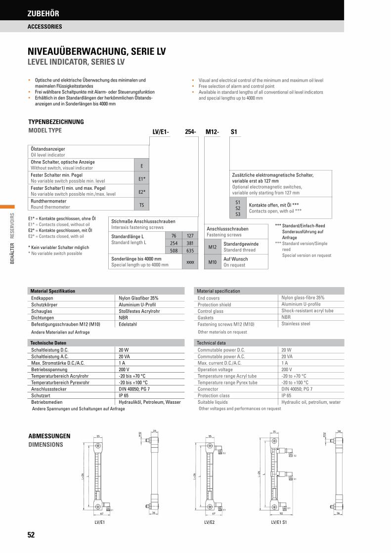
52
BEHÄ
LTER
R
ESER
VOIR
SZUBEHÖR
ACCESSORIES
NIVEAUÜBERWACHUNG, SERIE LV LEVEL INDICATOR, SERIES LV
ÖlstandsanzeigerOil level indicatorOhne Schalter, optische AnzeigeWithout switch, visual indicator E
Fester Schalter min. PegelNo variable switch possible min. level E1*
Fester Schalter1) min. und max. PegelNo variable switch possible min./max. level E2*
RundthermometerRound thermometer TS
Stichmaße AnschlussschraubenInteraxis fastening screws
Standardlänge LStandard length L
76 127
254 381
508 635
Sonderlänge bis 4000 mmSpecial length up to 4000 mm xxxx
AnschlussschraubenFastening screws
M12StandardgewindeStandard thread
M10Auf WunschOn request
Zusätzliche elektromagnetische Schalter,variable erst ab 127 mmOptional electromagnetic switches,variable only starting from 127 mm
S1S2S3
Kontakte offen, mit Öl ***Contacts open, with oil ***
LV/E1- M12- S1
*** Standard/Einfach-Reed Sonderausführung auf Anfrage
*** Standard version/Simple reed Special version on request
E1* = Kontakte geschlossen, ohne ÖlE1* = Contacts closed, without oilE2* = Kontakte geschlossen, mit ÖlE2* = Contacts closed, with oil
* Kein variabler Schalter möglich* No variable switch possible
• Optische und elektrische Überwachung des minimalen und maximalen Flüssigkeitsstandes
• Frei wählbare Schaltpunkte mit Alarm- oder Steuerungsfunktion• Erhältlich in den Standardlängen der herkömmlichen Ölstands-
anzeigen und in Sonderlängen bis 4000 mm
• Visual and electrical control of the minimum and maximum oil level• Free selection of alarm and control point• Available in standard lengths of all conventional oil level indicators
and special lengths up to 4000 mm
TYPENBEZEICHNUNG MODEL TYPE
Andere Spannungen und Schaltungen auf Anfrage
Material Spezifikation Material specificationEndkappen Nylon Glasfiber 35% End covers Nylon glass-fibre 35%Schutzkörper Aluminium U-Profil Protection shield Aluminium U-profileSchauglas Stoßfestes Acrylrohr Control glass Shock-resistant acryl tubeDichtungen NBR Gaskets NBRBefestigungsschrauben M12 (M10) Edelstahl Fastening screws M12 (M10) Stainless steel
Technische Daten Technical dataSchaltleistung D.C. 20 W Commutable power D.C. 20 WSchaltleistung A.C. 20 VA Commutable power A.C. 20 VAMax. Stromstärke D.C./A.C. 1 A Max. current D.C./A.C. 1 ABetriebsspannung 200 V Operation voltage 200 VTemperaturbereich Acrylrohr -20 bis +70 °C Temperature range Acryl tube -20 to +70 °CTemperaturbereich Pyrexrohr -20 bis +100 °C Temperature range Pyrex tube -20 to +100 °CAnschlussstecker DIN 40050; PG 7 Connector DIN 40050; PG 7Schutzart IP 65 Protection class IP 65Betriebsmedien Hydrauliköl, Petroleum, Wasser Suitable liquids Hydraulic oil, petrolium, water
Other voltages and performances on request
254-
ABMESSUNGENDIMENSIONS
LV/E1 LV/E2 LV/E1 S1
Andere Materialien auf Anfrage Other materials on request

53
BEHÄ
LTER
RE
SERV
OIRS
ZUBEHÖR
ACCESSORIES
G2- 650- 074- 230 WS- IP 65
GrundtypBasic type
EinschraubgewindeScrew-in thread
G1½
G2
Tauchlänge in mmImmersion length in mm
G1½ 400
G2650
950
Heizleistung in kWHeating capacity in kW
G1½0.37
1.00
0.80
G2
0.74
1.60
2.00
1.08
2.30
3.00
AnschlussspannungConnected load
230 WS230 V Wechselstrom230 V Alternating current
400 DS400 V Drehstrom400 V Three-phase alternating current
400 WS400 V Wechselstrom400 V Alternating current
SchutzartProtection class IP 65
ABMESSUNGEN DIMENSIONS
Stahlmantel mit WinkelverschraubungSteel casing with angular screw joint
SCHALTBILDER WIRING DIAGRAMS
Ø D
L
L2
L1
G
Ø D
1
PG
230/400 V DS
L3 PEL2L1
400 VWS
PEL2L1
230 VWS
PENL1
TypType
Tauchlänge LImmersion length L
[mm]
AnschlussspannungConnected load
[V]
HeizleistungHeating capacity
[kW]
Spez. Oberflächen-belastung
Special surface strain[W/cm2]
EinschränkungenRestrictions
230 WS 400 DS 0.37 0.7
G1½ 400 230 WS 400 DS 400 WS 1.00 2.0
0.80 1.5 0.7 W/cm2 für synthetische Ester
0.74 0.7 0.7 W/cm2 for synthetic estersG2 650 230 WS 400 DS 400 WS 1.60 1.5
2.00 2.0 1.5 W/cm2 für Mineralöle
1.08 0.7 1.5 W/cm2 for mineral oilsG2 950 230 WS 400 DS 400 WS 2.30 1.5
3.00 2.0
TypType
SW [mm]
G [mm]
L [mm]
L1 [mm]
L2 [mm]
D [mm]
D1 [mm]
PG [mm]
G1½ 60 1½‘‘ 400 25 96 42 49 11
G2 70 2‘‘ 650/950 26 106 52 59 16
EINSCHRAUBHEIZSTÄBE FÜR HYDRAULIKÖLSCREW-IN HEATING RODS FOR HYDRAULIC OIL
TYPENBEZEICHNUNG MODEL TYPE

54
BEHÄ
LTER
R
ESER
VOIR
S
• Kein Montageaufwand• Keine Schweißmuffen• Ideal für Nachrüstung• Vertikale und horizontale Anordnung möglich• Geringer Mindestölpegel• Haftmagnete zur Fixierung des Tauchheizers an Behälterboden,
Behälterwand oder Trennblech• Zusätzlich ziehen die Magnete metallische Teile aus dem Öl• Erwärmung von Hydrauliköl von 15 °C bis 50 °C
• No installation necessary• No welding box necessary• Ideal for retrofit• Vertical and horizontal mounting possible• Lower minimum oil level• Fixation of the plunger heater to the container base, wall or
separation metal plate by means of magnetic clamps• The magnetic clamps will also pull the metallic particles out of the oil• To heat up the hydraulic oil temperature between 15 °C and 50 °C
Typ Type
Ohne MagneteWithout magnets RH
Mit MagnetenWith magnets RHM
GrößeDimensions
250
256
500
506
1000
ThermostateinstellungThermostat setting
–40 °C*40 °C*
xxSonderSpecial
40RHM- 1000-
Temperaturintervall 3 °CTemperature interval 3 °C
* Standardeinstellung* Standard setting
AUFBAUGewendelter Rohrheizkörper 250, 500, 1000 W/230 V. Mineral- u. Rapsölbestän-diges 3-poliges Kunststoffkabel mit aufgeschobener Kabelverschraubung. Be-ständigkeit gegen andere Hydraulikflüssigkeiten auf Anfrage.
CONSTRUCTIONTubular heater coil 250, 500, 1000 W/230 V. Plastic cable (3 poles), resistant against mineral and rapeseed oil, with pushed-on cable screw joint. Resis-tance against other hydraulic liquids on request.
AUSLEGUNGSBEISPIELEXAMPLE OF DESIGN
Ein Behälter mit 630 l Volumen soll bei einer Umgebungstemperatur von 20 °C auf einer Öltemperatur von 45 °C gehalten werden ( t = 25 °C). Die hierfür erforderliche Heizleistung ergibt sich aus dem Schnittpunkt. Um die Aufrechterhaltung der Tem-peratur zu gewährleisten, ist das Heizelement mit dem nächst höheren Heizwert von 2 kW zu wählen. Bei Kaltstart empfiehlt sich, aus Gründen einer kürzeren Aufheizzeit, die Auswahl eines größeren Heizelementes (Leistungsfaktor 1,5 – 2,0).
A container with 630 l volume should be held at an oil temperature of 45 °C with an ambient temperature of 20 °C ( t = 25 °C). The heating capacity needed here arises out of the point of intersection. In order to maintain the tem-perature, a heating rod with the next higher heating capacity of 2 kW will have to be chosen. By cold starts and on grounds of a shorter heating period, it is recom-mended to choose a larger heating rod (capacity factor 1.5 to 2.0).
58.nim
70
L
Hydraulik-Stahlbehälter nach DIN24339Hydraulic steel reservoir acc. to DIN24339
BEISPIEL EXAMPLEErmittelte Leistung ~1,5 kW multipliziert mit Faktor 2,0 = 3 kW...Established capacity ~1.5 kW multiplied by factor 2.0 = 3 kW ….
TypType
HeizleistungHeating capacity
[W]
LängeLength [mm]
Spezifische OberflächenbelastungSpecial surface strain
[W/cm2]
EinschränkungenRestrictions
RH(M)250 250 250 1.2 0.6 W/cm2 für synthetische EsterRH(M)256 250 290 0.6 0.6 W/cm2 for synthetic estersRH(M)500 500 290 1.2
RH(M)506 500 390 0.6 1.2 W/cm2 für MineralöleRH(M)1000 1000 390 1.2 1.2 W/cm2 for mineral oils
TAUCHHEIZER, SERIE RH PLUNGE HEATER, SERIES RH
TYPENBEZEICHNUNG MODEL TYPE
AUSWAHLDIAGRAMM SELECTION DIAGRAM
Max. Verharrungstemperaturdifferenz bei R+L HYDRAULICS Tauchheizern und Ein-schraubheizstäben in Abhängigkeit der Behältergröße.
Max. maintainable temperature difference for R+L HYDRAULICS plunger heater and screw-in heating rods in relation to the container ’s size
10 °C
20 °C
30 °C
40 °C
50 °C
60 °C
5
4
32
1
3 kW
0,37 kW
0,25 kW
2000
]C°[t
1500 1000 630 400 250 160 100 63V[I]1250 800 300 200
2 kW0,5 kW
1 kW 0,75 kW
ZUBEHÖR
ACCESSORIES

55
BEHÄ
LTER
RE
SERV
OIRS
NOTIZENNOTES

EINFÜHRUNG WÄRMETAUSCHER
INTRODUCTION HEAT EXCHANGERS
56
OCN NebenstromkühleinheitOCN Offline Cooling Unit

EINFÜHRUNG WÄRMETAUSCHER
INTRODUCTION HEAT EXCHANGERS
ACN UND DCN ÖL-LUFT-KÜHLER 58ACN AND DCN OIL-AIR COOLERS
OCN NEBENSTROMKÜHLEINHEITEN 69OCN OFFLINE COOLING UNITS
BNZ ÖL-WASSER-KÜHLER 71BNZ OIL-WATER COOLERS
PK PLATTENWÄRMETAUSCHER 78PK PLATE HEAT EXCHANGERS
UKC ÖL-WASSER-WÄRMETAUSCHER 81UKC OIL-WATER HEAT EXCHANGERS
WÄRMETAUSCHERHEAT EXCHANGERS
57
WÄR
MET
AUSC
HER
HE
AT E
XCHA
NGE
RS
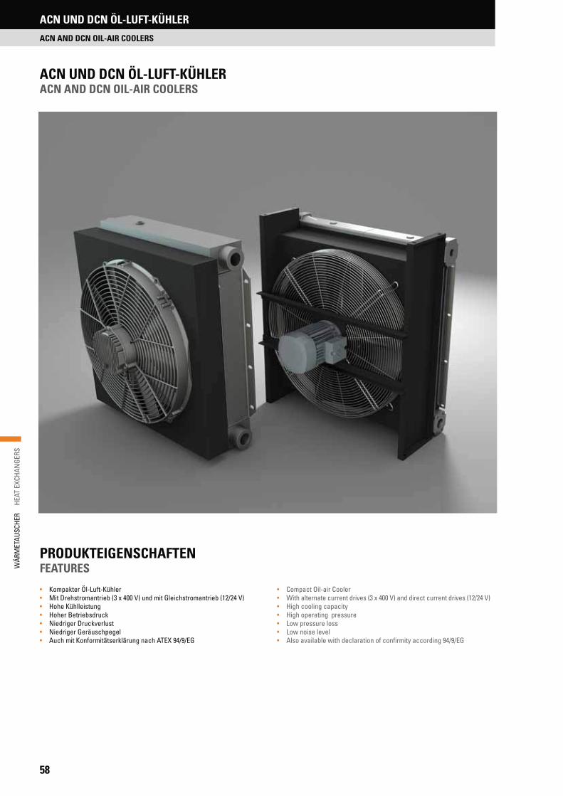
58
WÄR
MET
AUSC
HER
H
EAT
EXCH
ANGE
RSACN UND DCN ÖL-LUFT-KÜHLER
ACN AND DCN OIL-AIR COOLERS
• Kompakter Öl-Luft-Kühler• Mit Drehstromantrieb (3 x 400 V) und mit Gleichstromantrieb (12/24 V)• Hohe Kühlleistung• Hoher Betriebsdruck• Niedriger Druckverlust• Niedriger Geräuschpegel• Auch mit Konformitätserklärung nach ATEX 94/9/EG
PRODUKTEIGENSCHAFTENFEATURES
• Compact Oil-air Cooler• With alternate current drives (3 x 400 V) and direct current drives (12/24 V)• High cooling capacity• High operating pressure• Low pressure loss• Low noise level• Also available with declaration of confirmity according 94/9/EG
ACN UND DCN ÖL-LUFT-KÜHLERACN AND DCN OIL-AIR COOLERS

59
WÄR
MET
AUSC
HER
HE
AT E
XCHA
NGE
RS
ACN UND DCN ÖL-LUFT-KÜHLER
ACN AND DCN OIL-AIR COOLERS
Kühler: Aluminium, Weißaluminium RAL 9006Haube/ Füße: Stahl, Tiefschwarz RAL 9005Lüfter: PPG (Sondermaterial auf Anfrage)Lüftergitter ACN: Stahl, silber chromatiert, Chrom (VI) freiLüfter DCN: Kunststoff mit integriertem Elektromotor
Neben einem kompakten Design und einem hohen Wirkungsgrad hat R+L HYDRAULICS bei der Entwicklung seiner Öl-Luft-Kühler besonderen Wert auf eine möglichst geringe Geräuschentwicklung gelegt. Hierfür wurden die ein-gesetzten Kühlpakete und Ventilatoren entsprechend optimiert.
Derzeit sind 11 Baugrößen mit einer Kühlleistung von 4,4 kW bis 140 kW bei 40 °C Eintrittstemperaturdifferenz verfügbar. Die Kühlpakete der Baugrößen 5 bis 60 sind in einer Einweg- und Zweiwegausführung erhältlich. Dadurch steht bei diesen Abmessungen jeweils eine Version mit geringem Druckverlust und eine Version mit hoher Leistung zur Verfügung.
Durch den modularen Aufbau sind die ÖL-Luft-Kühler sowohl für stationäre als auch für mobile Hydraulikanlagen geeignet. Zu diesem Konzept gehört auch der Einsatz von IEC Normmotoren ab der Baugröße ACN-10. Daher können die Öl-Luftkühler auch mit Motoren für Sonderspannungen geliefert werden.
Maximale Betriebsdrücke:
20 bar dynamisch26 bar statisch
Cooler: Aluminium, white aluminium RAL 9006Cover/feet: Steel, jet black RAL 9005Fan: PPG (special material on request)Fan guard ACN: Steel, silver chromated Chrome (VI) freeCooler DCN: Plastic material with integrated electric motor
R+L HYDRAULICS’ oil-air coolers offer more than just a compact design and high efficiency – the cooling units and fans fitted were also optimized to en-sure that the coolers run with a minimum of noise.
The current range consists of 11 sizes with cooling capacities between 4.4 kW and 140 kW at 40 °C inlet temperature differential, with one-pass or two-pass versions of unit sizes 5 to 60 available. Two versions in sizes 5 to 60 are available: one with low pressure drop, the other with high cooling perfor-mance.
Our oil-air coolers are constructed on a modular basis, so they are suitable for both static and mobile hydraulic systems. From size ACN-10 IEC onwards, standard motors are used, so the coolers can be operated with special volt-ages.
Maximum working pressures:
20 bar dynamic26 bar static
TYPENBEZEICHNUNGMODEL TYPE
* Auf Anfrage On request
Strömungsrichtung der Luft:S = Saugend (vom Kühlpaket zum Motor);B = Drückend (vom Motor zum Kühlpaket)
Direction of Air Flow:S = Suction (cooling package to motor);B = Blowing (motor to cooling package)
Schutz für Kühlpaket:0 = ohne G = SchutzgitterF = Schutzgitter mit Filtervlies
Guard for cooling element:0 = without G = guardF = guard with filter fleece
Sonderausführungen:0 = ohneMA = MarineausführungEXE = gem. ATEX 94/9/EG Motor mit erhöhter SicheheitEXD = gem. ATEX 94/9/EG Motor druckfest gekapselt
Special designs:0 = withoutMA = marine constructionEXE = according ATEX 94/9/EG motor with increased protectionEXD = according ATEX 94/9/EG motor with pressure-resistant casing
Ausführungen nach Zeichnung:0 = ohnefortlaufende Nummer
Other special designs:0 = withoutconsecutive number
Öl-Luft-Kühler: ACN = mit Drehstromantrieb;DCN = mit Gleichstromantrieb
(für mobile Anwendungen)
Oil-Air Cooler:ACN = with Alternate Current Drive;DCN = with Direct Current Drive
(for mobile applications)
Baugrößen: 5; 10; 20; 30; 40; 50; 60; 70; 80; 90; 100
Sizes: 5; 10; 20; 30; 40; 50; 60; 70; 80; 90; 100
Wege: 1 = Einweg od. 2 = Zweiwege
Pass Through: 1 = one pass or 2 = two pass
Nennspannung des Motors:400 = 230/400 V 50 Hz drei Phasen230 = 230 V/50 Hz Wechselstrom12/24 = 12/24 V Gleichstrom
Nominal Voltage of Motor:400 = 230/400 V 50 Hz three phase230 = 230 V/50 Hz AC12/24 = 12/24 V DC
Temperaturschalter:0 = ohne TS42O = TS-4-2-OTS52O = TS-5-2-OTS62O = TS-6-2-O TS72O = TS-7-2-OWeitere Optionen siehe Seite 68
Temperature switch:0 = withoutTS42O = TS-4-2-OTS52O = TS-5-2-OTS62O = TS-6-2-O TS72O = TS-7-2-OOther options see page 68
Bypassventil:0 = ohne TB40 = temperaturgeregelter Bypass bis 40 °CTB50 = temperaturgeregelter Bypass bis 50 °CDB2 = druckgeregelter Bypass ab 2 bar DB5 = druckgeregelter Bypass ab 5 bar
Bypass valve:0 = withoutTB40 = temperature regulated bypass till 40 °CTB50 = temperature regulated bypass till 50 °CDB2 = pressure regulated bypass from 2 barDB5 = pressure regulated bypass from 5 bar
Polzahl des Motors: 2, 4, 6, 8
Number of poles: 2, 4, 6, 8
*ACN 60 1 400.4 S TS520 TB50 0 EXE S76
MATERIALIENMATERIALS

60
WÄR
MET
AUSC
HER
H
EAT
EXCH
ANGE
RSACN UND DCN ÖL-LUFT-KÜHLER
ACN AND DCN OIL-AIR COOLERS
• Bei der Installation der Kühler ist darauf zu achten, dass die Kühlluft frei ein- und ausströmen kann. Der Abstand zur Wand (A) sollte mindestens der Höhe des Kühlpaketes entsprechen (siehe Abbildung 1). Andere Luftströme dürfen den Kühlluftstrom der ACN und DCN Öl-Luft-Kühler nicht kreuzen.
• Bei der Aufstellung in geschlossenen Räumen muss auf eine ausreichende Frischluftzufuhr geachtet werden, damit die Kühlleistung durch die bereits erwärmte Luft nicht beeinträchtigt wird.
• Bei niedrigen Umgebungstemperaturen erhöht sich die Ölviskosität. Da-durch erhöht sich der Druckverlust beim Anlauf der Kühlung. Wenn der Druckverlust beim Anlauf den maximal zulässigen Betriebsdruck über-steigt, ist ein Thermo-Bypassventil oder ein Druck-Bypassventil parallel zum Öl-Luft-Kühler zu montieren.
• Die ACN-Öl-Luft-Kühler der Baugrößen 10 bis 100 sind für eine vertikale Montage mittels der integrierten Fußbefestigung vorgesehen. Die Öl-Luft-Kühler der Baugrößen ACN-70 bis ACN-100 verfügen an der Oberseite des Gehäuses über zusätzliche Befestigungspunkte. Sie können daher auch waagerecht montiert werden. Die ACN-Kühler der Baugröße 5 und die DCN-Öl-Luft-Kühler werden mit Hilfe von 2 Leisten am Kühlpaket befestigt.
• Der ölseitige Anschluss der Kühler erfolgt an den dafür vorgesehenen und entsprechend markierten Anschlussgewinden am oberen und unteren Sammeltank des Kühlpaketes (siehe Abbildung 2 + 3). Der jeweils nicht be-nötigte Anschluss wird ab Werk mit einem Verschlussstopfen verschlos-sen.
• Der nicht benötigte Anschlussstutzen kann ebenso wie die Anschlussstut-zen M22 x 1,5, G3/8“ und G1“ zum Anschluss von Messfühlern oder Schal-tern (Druck, Temperatur) verwendet werden.
• Beim elektrischen Anschluss des Elektromotors ist darauf zu achten, dass sich der Ventilator in Richtung des Drehrichtungspfeils, der auf dem Ge-häuse des Kühlers angebracht ist, dreht.
• Die Öl-Luft-Kühler sind für eine maximale Umgebungstemperatur von 40 °C und eine maximale Öltemperatur von 120 °C ausgelegt.
• When installing the cooler, please ensure that the cooling air can flow in and out freely. The distance from the wall (A) should be equal to or greater than the height of the cooling unit (see Figure 1). Ensure that no other cur-rents of air interferes with the cooling air flow of ACN and DCN oil-air cool-ers.
• If the cooler is operated indoors, there must always be an adequate supply of fresh air to prevent any negative effect on cooling performance by the presence of warm air in the room.
• Low ambient temperatures increase oil viscosity, leading to a high pres-sure drop when the cooling process starts. If the start-up pressure drop exceeds the maximum permitted operating pressure, a thermal bypass valve or pressure bypass valve must be installed parallel to the oil-air-cooler.
• ACN oil-air coolers in sizes 10 to 100 are intended for vertical installation using the integrated foot brackets. The oil-air cooler’s size ACN-70 to ACN- 100 have additional mounting holes at the top of the housing. Therefore they are also suitable for horizontal mounting. The ACN cooler in size 5 and all DCN oil-air coolers are attached with mounting bars which are at the cooling package.
• The oil-side cooler connection is made on the upper and lower collecting tank of the cooling unit, using the marked screw connectors provided (see Figures 2 + 3 for details). The connection not in use is closed by a factory-fitted stopper.
• The unused connecting pipe can, in the same way as connecting pipes M22x1.5, G3/8“and G1”, also be used to fit measuring probes or switches (pressure, temperature).
• Ensure that the electric motor is wired so that the fan rotates in the direc-tion of the arrow marking on the cooler housing.
• The oil-air-coolers were designed for use at an ambient temperature not exceeding 40 °C and a maximum oil temperature of 120 °C.
Abb. 1 Figure1
Abb. 2: EinwegFigure 2: One pass
Abb. 3 ZweiwegeFigure 3: Two pass
LuftstromAir Flow
A A
A
HINWEISE ZUR INSTALLATION, PLATZBEDARF UND MONTAGEINSTALLATION, NOTES SPACE REQUIREMENTS AND FITTING INSTRUCTIONS

61
WÄR
MET
AUSC
HER
HE
AT E
XCHA
NGE
RS
ACN UND DCN ÖL-LUFT-KÜHLER
ACN AND DCN OIL-AIR COOLERS
ABMESSUNGEN ACN BAUGRÖSSEN 5 BIS 60DIMENSIONS ACN SIZES 5 TO 60
BaureihenProduct series
A[mm]
B[mm]
C[mm]
D[mm]
E[mm]
F[mm]
G[mm]
H[mm]
I[mm]
J[mm]
K
ACN-5* 340 300 142 -** -** 272 25 290 45 97 G1½“ACN-10 430 347 396 199 100 239 40 360 63 128 G1"ACN-20 430 347 426 230 100 239 40 360 94 128 G1"ACN-30 550 490 430 213 130 377 60 460 63 163 G1"ACN-40 550 490 461 244 130 377 60 460 94 163 G1"ACN-50 712 670 470 213 130 554 72 610 63 183 G1½“ACN-60 712 670 500 244 130 554 72 610 94 183 G1½“
TECHNISCHE DATEN TECHNICAL DATA
BaureihenProduct series
MotorMotor
[kW/UPM]
StromaufnahmePower consumption
[A]
LuftdurchsatzAir flow
[m3/sek.]
GeräuschpegelNoise level1 m [dB(A)]
GeräuschpegelNoise level7 m [dB(A)]
GewichtWeight
[kg]
BestellcodeOrder code
ACN-5 0.11/2450 0.51 0.24 69 – 8 ACN-5-X-230.1-SACN-5 0.10/2500 0.20 0.23 69 – 8 ACN-5-X-400.2-SACN-10 0.37/3000 1.00 0.41 74 57 17 ACN-10-X-400.2-SACN-10 0.25/1500 0.80 0.24 61 44 17 ACN-10-1-400.4-SACN-20 0.37/3000 1.00 0.42 76 59 20 ACN-20-X-400.2-SACN-30 0.25/1500 0.80 0.62 70 53 25 ACN-30-X-400.4-S
ACN-30 0.18/1000 0.70 0.49 62 45 26 ACN-30-1-400.6-S
ACN-40 0.25/1500 0.80 0.63 72 55 32 ACN-40-X-400.4-SACN-50 0.55/1500 1.50 1.42 77 60 40 ACN-50-X-400.4-SACN-50 0.18/1000 0.70 0.88 67 50 37 ACN-50-1-400.6-SACN-60 0.55/1500 1.50 1.25 77 60 49 ACN-60-X-400.4-S
Der Geräuschpegel kann um ±3 dB(A) variieren. Dies ist auf eventuelle Reflexionen umstehender Gegenstände, Eigenfrequenzen u.ä. zurückzuführen. Die Geräuschmessungen wurden bei halb-sphärischer Streuung durchgeführt.The specified noise level may vary by ±3 dB(A). This is due to possible reflections from surrounding objects, natural frequencies or similar. The noise measurements were conducted at half-spherical diffusion.
X = Einweg oder ZweiwegeX = One pass or two pass
* Baugröße ACN-5 nicht mit IEC Normmotor erhältlich. Size ACN-5 not available with IEC standard motor.** ACN-5 ohne Montagefüße ACN-5 without mounting brackets
G3/8"
M22 x 1,5
Ø12 x 20
K (3x)
BF
A
I J
= =
D E
CG
H

62
WÄR
MET
AUSC
HER
H
EAT
EXCH
ANGE
RS
ABMESSUNGEN ACN BAUGRÖSSEN 70 BIS 100 DIMENSIONS ACN SIZES 70 TO 100
BaureihenProduct series
A[mm]
B[mm]
C[mm]
D[mm]
E[mm]
F[mm]
G[mm]
H[mm]
I[mm]
J[mm]
K
ACN-70 900 794 585 119 175 759 85 760 94 225 SAE 2" + G1½"ACN-80 1000 908 571 119 175 873 85 860 94 225 SAE 2" + G1½"ACN-90 1100 1008 647 119 200 973 85 960 94 250 SAE 2" + G1½"ACN-100 1200 1075 647 119 200 1040 85 1060 94 250 SAE 2" + G1½"
BaureihenProduct series
MotorMotor
[kW/UPM]
StromaufnahmePower consumption
[A]
LuftdurchsatzAir flow
[m3/sek.]
GeräuschpegelNoise level1 m [dB(A)]
GeräuschpegelNoise level7 m [dB(A)]
GewichtWeight
[kg]
BestellcodeOrder code
ACN-70 0.75/1000 2.43 1.78 77 64 91 ACN-70-1-400.6-S
ACN-70 0.37/750 1.60 1.30 69 56 91 ACN-70-1-400.8-S
ACN-80 1.1/1000 3.15 2.82 79 68 115 ACN-80-1-400.6-S
ACN-80 0.55/750 2.04 2.05 72 60 115 ACN-80-1-400.8-S
ACN-90 2.2/1000 5.35 3.60 85 72 140 ACN-90-1-400.6-S
ACN-90 1.1/750 3.25 2.56 76 64 134 ACN-90-1-400.8-S
ACN-100 2.2/1000 5.35 4.48 84 71 160 ACN-100-1-400.6-S
ACN-100 1.1/750 3.25 3.20 76 64 154 ACN-100-1-400.8-S
Der Geräuschpegel kann um ±3 dB(A) variieren. Dies ist auf eventuelle Reflexionen umstehender Gegenstände, Eigenfre-quenzen u.ä. zurückzuführen. Die Geräuschmessungen wurden bei halb-sphärischer Streuung durchgeführt.The specified noise level may vary by ±3 dB(A). This is due to possible reflections from surrounding objects, natural frequencies or similar. The noise measurements were conducted at half-spherical diffusion.
G3/8"
K (3x)
A
G 1“
F
B
GH
I J
= =
Ø 15 (8 x)
D E
C
TECHNISCHE DATEN TECHNICAL DATA
ACN UND DCN ÖL-LUFT-KÜHLER
ACN AND DCN OIL-AIR COOLERS

63
WÄR
MET
AUSC
HER
HE
AT E
XCHA
NGE
RS
ACN UND DCN ÖL-LUFT-KÜHLER
ACN AND DCN OIL-AIR COOLERS
BaureihenProduct Series
A[mm]
B[mm]
C[mm]
D[mm]
E[mm]
F[mm]
G[mm]
H[mm]
I[mm]
DCN-5 340 300 162 45 272 290 105 130 G½"DCN-10 420 347 220 63 317 360 110 100 G1"DCN-20 420 347 251 94 317 360 110 100 G1"DCN-30 520 490 221 63 455 460 95 110 G1"DCN-40 520 490 252 94 455 460 95 110 G1"
BaureihenProduct Series
StromaufnahmePower consumption
[A]
LuftdurchsatzAir flow
[m3/sek.]
GeräuschpegelNoise level1 m [dB(A)]
GeräuschpegelNoise level7 m [dB(A)]
GewichtWeight
[kg]
Bestellcode*Order code*
12 V 24 VDCN-5 11.8 6.2 0.23 n.a. n.a. 8 DCN-5-X-Y-SDCN-10 15.0 7.8 0.49 79 64 10 DCN-10-X-Y-SDCN-20 15.0 7.8 0.45 79 64 13 DCN-20-X-Y-SDCN-30 17.2 8.5 0.84 84 67 17 DCN-30-X-Y-S
DCN-40 17.2 8.5 0.74 84 67 24 DCN-40-X-Y-S
X = Einweg oder Zweiwege Y = 12 V oder 24 V X = One pass or two pass Y =12 V or 24 V
Der Geräuschpegel kann um ±3 dB(A) variieren. Dies ist auf eventuelle Reflexionen umstehender Gegenstände, Eigenfre-quenzen u.ä. zurückzuführen. Die Geräuschmessungen wurden bei halb-sphärischer Streuung durchgeführt.The specified noise level may vary by ±3 dB(A). This is due to possible reflections from surrounding objects, natural frequencies or similar. The noise measurements were conducted at half-spherical diffusion.
G3/8"
B
M22 x 1,5
I (3x)
E
HH
H
G
C
D
ABMESSUNGEN DCN DIMENSIONS DCN
TECHNISCHE DATEN TECHNICAL DATA
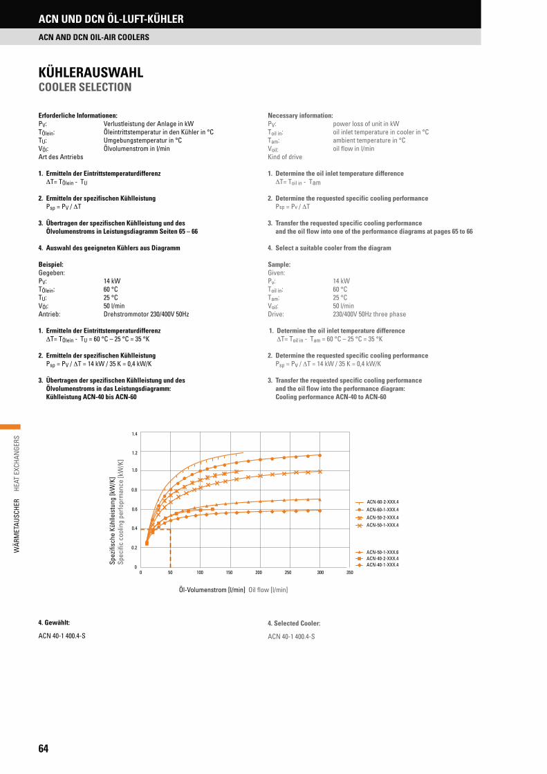
64
WÄR
MET
AUSC
HER
H
EAT
EXCH
ANGE
RS
Erforderliche Informationen:PV: Verlustleistung der Anlage in kWTÖlein: Öleintrittstemperatur in den Kühler in °CTU: Umgebungstemperatur in °CVÖl: Ölvolumenstrom in l/minArt des Antriebs
1. Ermitteln der Eintrittstemperaturdifferenz T= TÖlein - TU
2. Ermitteln der spezifischen Kühlleistung Psp = PV / T
3. Übertragen der spezifischen Kühlleistung und des Ölvolumenstroms in Leistungsdiagramm Seiten 65 – 66
4. Auswahl des geeigneten Kühlers aus Diagramm
Beispiel:Gegeben:PV: 14 kWTÖlein: 60 °CTU: 25 °CVÖl: 50 l/minAntrieb: Drehstrommotor 230/400V 50Hz
1. Ermitteln der Eintrittstemperaturdifferenz T= TÖlein - TU = 60 °C – 25 °C = 35 °K
2. Ermitteln der spezifischen Kühlleistung Psp = PV / T = 14 kW / 35 K = 0,4 kW/K
3. Übertragen der spezifischen Kühlleistung und des Ölvolumenstroms in das Leistungsdiagramm: Kühlleistung ACN-40 bis ACN-60
KÜHLERAUSWAHLCOOLER SELECTION
4. Gewählt:
ACN 40-1 400.4-S
Necessary information:PV: power loss of unit in kWToil in: oil inlet temperature in cooler in °CTam: ambient temperature in °CVoil: oil flow in l/minKind of drive
1. Determine the oil inlet temperature difference T= Toil in - Tam
2. Determine the requested specific cooling performance Psp = Pv / T
3. Transfer the requested specific cooling performance and the oil flow into one of the performance diagrams at pages 65 to 66
4. Select a suitable cooler from the diagram
Sample:Given:Pv: 14 kWToil in: 60 °CTam: 25 °CVoil: 50 l/minDrive: 230/400V 50Hz three phase
1. Determine the oil inlet temperature difference T= Toil in - Tam = 60 °C – 25 °C = 35 °K
2. Determine the requested specific cooling performance Psp = Pv / T = 14 kW / 35 K = 0,4 kW/K
3. Transfer the requested specific cooling performance and the oil flow into the performance diagram: Cooling performance ACN-40 to ACN-60
4. Selected Cooler:
ACN 40-1 400.4-S
ACN UND DCN ÖL-LUFT-KÜHLER
ACN AND DCN OIL-AIR COOLERS
Öl-Volumenstrom [l/min] Oil flow [l/min]
Spez
ifisc
he K
ühlle
istu
ng [k
W/K
]Sp
ecifi
c co
olin
g pe
rfopr
man
ce [k
W/K
]
0
0.2
0.4
0.6
0.8
1.0
1.2
1.4
0 50 100 150 200 250 300 350
ACN-40-1-XXX.4 ACN-40-2-XXX.4 ACN-50-1-XXX.6
ACN-50-1-XXX.4 ACN-50-2-XXX.4
ACN-60-1-XXX.4
ACN-60-2-XXX.4

65
WÄR
MET
AUSC
HER
HE
AT E
XCHA
NGE
RS
ACN UND DCN ÖL-LUFT-KÜHLER
ACN AND DCN OIL-AIR COOLERS
Spez
ifisc
he K
ühlle
istu
ng [k
W/K
]Sp
ecifi
c co
olin
g pe
rfopr
man
ce [k
W/K
]
Öldurchfluss [l/min] Oil flow [l/min]
Spez
ifisc
he K
ühlle
istu
ng [k
W/K
]Sp
ecifi
c co
olin
g pe
rfopr
man
ce [k
W/K
]KÜHLLEISTUNG ACN-5-1 BIS ACN-30-2COOLING PERFORMANCE ACN-5-1 TO ACN-30-2
KÜHLLEISTUNG ACN-40 BIS ACN-60COOLING PERFORMANCE ACN-40 TO ACN-60
Öldurchfluss [l/min] Oil flow [l/min]
0
0.05
0.10
0.15
0.20
0.25
0.30
0.35
0.40
0.45
0.50
0 20 40 60 80 100 120 140 160 ACN-5-1-XXX.2 ACN-5-2-XXX.2
ACN-10-1-XXX.2
ACN-10-1-XXX.4
ACN-10-2-XXX.2
ACN-20-1-XXX.2 ACN-20-2-XXX.2
ACN-30-1-XXX.6
ACN-30-1-XXX.4 ACN-30-2-XXX.4
0
0.2
0.4
0.6
0.8
1.0
1.2
1.4
0 50 100 150 200 250 300 350
ACN-40-1-XXX.4 ACN-40-2-XXX.4 ACN-50-1-XXX.6
ACN-50-1-XXX.4 ACN-50-2-XXX.4
ACN-60-1-XXX.4
ACN-60-2-XXX.4

66
WÄR
MET
AUSC
HER
H
EAT
EXCH
ANGE
RSACN UND DCN ÖL-LUFT-KÜHLER
ACN AND DCN OIL-AIR COOLERS
Die spezifischen Kühlleistungen für ACN- und DCN-Öl-Luft-Kühler beziehen sich auf eine Öleintrittstemperatur von 60 °C und eine Umgebungstemperatur von 20 °C. Das bedeutet eine Eintrittstemperaturdifferenz von 40 °C. Toleranz ± 5 %
The specific cooling performances of ACN and DCN heat exchangers are based on an oil inlet temperature of 60 °C and an ambient tempe-rature of 20 °C. This means an inlet temperature difference of 40 °C. Tolerance ± 5 %
KÜHLLEISTUNG ACN-70-1 BIS ACN-100-1COOLING PERFORMANCE ACN-70-1 TO ACN-100-1
Spez
ifisc
he K
ühlle
istu
ng [k
W/K
]Sp
ecifi
c co
olin
g pe
rfopr
man
ce [k
W/K
]
Öldurchfluss [l/min] Oil flow [l/min]
KÜHLLEISTUNG DCN-5-1 BIS DCN-40-1 COOLING PERFORMANCE DCN-5-1 TO DCN-40-1
Spez
ifisc
he K
ühlle
istu
ng [k
W/K
]Sp
ecifi
c co
olin
g pe
rfopr
man
ce [k
W/K
]
Öldurchfluss [l/min] Oil flow [l/min]
0
0.5
1.0
1.5
2.0
2.5
3.0
3.5
4.0
0 100 200 300 400 500 600 700
ACN-70-1-400.6-S
ACN-70-1-400.8-S
ACN-80-1-400.6-S
ACN-80-1-400.8-S
ACN-90-1-400.6-S
ACN-90-1-400.8-S
ACN-100-1-400.6-S
ACN-100-1-400.8-S
0
0.1
0.2
0.3
0.4
0.5
0.6
0.7
0 20 40 60 80 100 120 140
DCN-5-1-XX-S DCN-5-2-XX-S
DCN-10-1-XX-S DCN-10-2-XX-S
DCN-20-1-XX-S DCN-20-2-XX-S
DCN-30-1-XX-S DCN-30-2-XX-S
DCN-40-1-XX-S DCN-40-2-XX-S
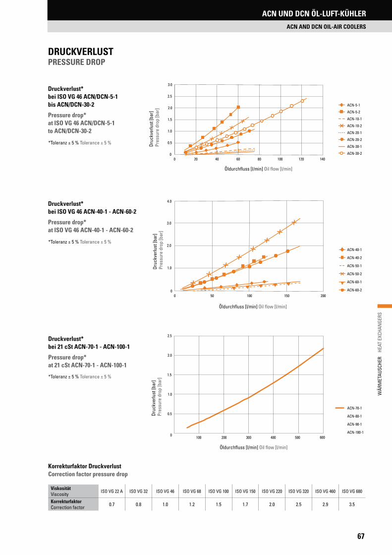
67
WÄR
MET
AUSC
HER
HE
AT E
XCHA
NGE
RS
ACN UND DCN ÖL-LUFT-KÜHLER
ACN AND DCN OIL-AIR COOLERS
Druc
kver
lust
[bar
]
Pres
sure
dro
p [b
ar]
Druckverlust* bei ISO VG 46 ACN/DCN-5-1 bis ACN/DCN-30-2
Pressure drop* at ISO VG 46 ACN/DCN-5-1 to ACN/DCN-30-2
Öldurchfluss [l/min] Oil flow [l/min]
Druckverlust* bei ISO VG 46 ACN-40-1 - ACN-60-2
Pressure drop* at ISO VG 46 ACN-40-1 - ACN-60-2
Öldurchfluss [l/min] Oil flow [l/min]
*Toleranz ± 5 % Tolerance ± 5 %
ViskositätViscosity
ISO VG 22 A ISO VG 32 ISO VG 46 ISO VG 68 ISO VG 100 ISO VG 150 ISO VG 220 ISO VG 320 ISO VG 460 ISO VG 680
KorrekturfaktorCorrection factor 0.7 0.8 1.0 1.2 1.5 1.7 2.0 2.5 2.9 3.5
Korrekturfaktor Druckverlust Correction factor pressure drop
Druckverlust* bei 21 cSt ACN-70-1 - ACN-100-1
Pressure drop* at 21 cSt ACN-70-1 - ACN-100-1
Druc
kver
lust
[bar
] Pr
essu
re d
rop
[bar
]
Öldurchfluss [l/min] Oil flow [l/min]
DRUCKVERLUSTPRESSURE DROP
Druc
kver
lust
[bar
]
Pres
sure
dro
p [b
ar]
*Toleranz ± 5 % Tolerance ± 5 %
*Toleranz ± 5 % Tolerance ± 5 %
0
0.5
1.0
1.5
2.0
2.5
3.0
0 20 40 60 80 100 120 140
ACN-5-1
ACN-5-2 ACN-10-1 ACN-10-2 ACN-20-1 ACN-20-2 ACN-30-1 ACN-30-2
0
1.0
2.0
3.0
4.0
0 50 100 150 200
ACN-40-1
ACN-40-2
ACN-50-1
ACN-50-2
ACN-60-1
ACN-60-2
0
0.5
1.0
1.5
2.0
2.5
100 200 300 400 500 600
ACN-70-1
ACN-80-1
ACN-90-1
ACN-100-1

68
WÄR
MET
AUSC
HER
H
EAT
EXCH
ANGE
RSACN UND DCN ÖL-LUFT-KÜHLER
ACN AND DCN OIL-AIR COOLERS
TS - 4 - 2 - 0
Kontakttyp: O = normal offen; S = normal geschlossen; W = WechselschalterType of electric contact: O = normally open; S = normally closed;
W = toggle switch
Hydraulikanschluss: 2 = G3/8“ ; 3 = M 22 x 1,5Hydraulic connection: 2 = G3/8“ ; 3 = M 22 x 1,5
Schalttemperatur: 4 = 40 °C; 5 = 50 °C; 6 = 60 °C; 7 = 70 °CSwitching temperature: 4 = 40 °C; 5 = 50 °C; 6 = 60 °C; 7 = 70 °C
Typ: TS = Temperaturschalter Standard, TC = Temperaturschalter CompactType: TS = Temperature switch standard, TC = Temperature switch compact
Material: BrassOperating temperature: -20 °C to 120 °CMax. operating pressure: 200 barSwitching accuracy: ± 3,5 °CType of electric contact: Normally open, normally closed, Toggle switchFixed hysteresis value: ~12 °C Body: Hexagonal, CH 27Electric protection according EN60529: IP65Electric connection: DIN43650, Type AMax. electrical load AC: 220 V / 10 A Max. electrical load DC: 24 V / 5 A
Material: BrassOperating temperature: -20 °C to 120 °CMax. operating pressure: 200 barSwitching accuracy: ± 3,5 °CType of electric contact: Normally open, normally closedFixed hysteresis value: ~12 °C Case: Hexagonal, CH 24 (G3/8”), CH 27 (M 22 x 1,5)Electric protection according EN60529: IP00Electric connection: Fast-On 6.3 x 0.8 mmMax. electrical load AC: 220 V / 10 A Max. electrical load DC: 24 V / 5 A
Material: MessingBetriebstemperatur: -20 °C bis 120 °CMaximaler Betriebsdruck: 200 barSchaltgenauigkeit: ± 3,5 °CKontakttyp: Normal offen, Normal geschlossenFest eingestellter Hysterese Wert: ~12 °C Gehäuse: Sechskant, Schlüsselweite 24 (G3/8“), 27 (M 22 x 1,5)Elektrische Schutzklasse nach EN60529: IP00Elektrischer Anschluss: Fast-On 6,3 x 0,8 mmMax. elektrische Belastung AC: 220 V / 10 A Max. elektrische Belastung DC: 24 V / 5 A
Material: MessingBetriebstemperatur: -20 °C bis 120 °CMaximaler Betriebsdruck: 200 barSchaltgenauigkeit: ± 3,5 °CKontakttyp: Normal offen, Normal geschlossen, Wechselschalter Fest eingestellter Hysterese Wert: ~12 °C Gehäuse: Sechskant, Schlüsselweite 27Elektrische Schutzklasse nach EN60529: IP65Elektrischer Anschluss: DIN43650, Form AMax. elektrische Belastung AC: 220 V / 10 A Max. elektrische Belastung DC: 24 V / 5 A
THERMOSCHALTER STANDARDTHERMOSWITCHES STANDARD
THERMOSCHALTER COMPACTTHERMOSWITCHES COMPACT
TYPENBEZEICHNUNGMODEL TYPE
Elektrischer AnschlussFast-On 6,3 x 0,8 mmElectric connectionFast-On 6.3 x 0.8 mm
Schlüsselweite
Hydraulik-AnschlussWrench size
Hydraulic connnection
Elektrischer Anschlussnach DIN 43650Electric connectionacc. DIN 43650
Schlüsselweite
Hydraulik-AnschlussWrench size
Hydraulic connnection
27
ca. 6
0
TECHNISCHE DATEN TECHNICAL DATA
TECHNISCHE DATEN TECHNICAL DATA

69
WÄR
MET
AUSC
HER
HE
AT E
XCHA
NGE
RS
• Kompaktes Design• Hohe Kühlleistung• Effiziente Motoren• Niedriger Geräuschpegel
• Compact design• High cooling capacity• Efficient motors• Low noise level
Die OCN-Baureihe ist eine Erweiterung der ACN Öl-Luft-Kühler Serie. Durch die integrierte Pumpe können die OCN Nebenstromkühleinheiten als eigen-ständige Baugruppe unabhängig von dem Hauptstrom der Hydraulikanlage betrieben werden. Das gewährleistet eine kontinuierliche Kühlung der Hy-draulikanlage und schützt den Kühler gegen Beschädigungen durch Druck-spitzen. Darüber hinaus lassen sich die OCN Nebenstromkühleinheiten auch einfach nachrüsten. Auf Anfrage können die OCN Nebenstromkühleinheiten auch mit Filter und separatem Temperaturschalter geliefert werden.
The OCN-Series is an extension of the ACN oil-air cooler line. Due to the in-tegrated pump, the OCN offline cooling units may operate independent of the main flow of the hydraulic system. This ensures a continuous cooling of the hydraulic system and protects the radiator against damage from pressure peaks. In addition, the OCN offline cooling units are easilyto be mounted sub-sequently. On request the OCN offline cooling units can be supplied with a filter and separate temperature switch.
PRODUKTEIGENSCHAFTENFEATURES
OCN NEBENSTROMKÜHLEINHEITEN
OCN OFFLINE COOLING UNITS
OCN NEBENSTROMKÜHLEINHEITENOCN OFFLINE COOLING UNITS

70
WÄR
MET
AUSC
HER
H
EAT
EXCH
ANGE
RS
BaureihenProduct series
A[mm]
B[mm]
C[mm]
D[mm]
E[mm]
F[mm]
G[mm]
H[mm]
I[mm]
J K L[mm]
M[mm]
OCN-10-2-400.4-S-20
439 347 444
57684.5
239 40 36063
G1" G1"
538
220OCN-10-2-400.4-S-40 572 534OCN-20-2-400.4-S-20 607
115.5 94569
OCN-20-2-400.4-S-40 602 564OCN-30-2-400.4-S-20
559 490 580
61183.0
377 60 46063
573
290OCN-30-2-400.4-S-40 606 568OCN-40-2-400.4-S-60
712 114.0 94
G1½" G1½"
662OCN-40-2-400.4-S-80OCN-50-2-400.4-S-60
721 670 775702 95.0
554 72 61063 650
377OCN-50-2-400.4-S-80OCN-60-2-400.4-S-60
733 126.0 94 682OCN-60-2-400.4-S-80
OCN NEBENSTROMKÜHLEINHEITENOCN OFFLINE COOLING UNITS
Max. Systemdruck: 10 barMax. Betriebstemperatur: -20 °C bis +120 °CBetriebsviskosität: 10 – 300 cStMedien: HLP, Synthetische Öle, Wasser-Glykol
(Glykolanteil > 40 %)Spannung: 230/400 V 50 Hz, 400/690 V 50 Hz
Max. internal operating pressure: 10 barMax. operating temperature: -20 °C to 120 °COperating viscosity: 10 – 300 cStMedia: HLP, synthetic oils, water glycol
(glycol contend > 40 %)Voltage: 230/400 V 50 Hz, 400/690 V 50 Hz
BaureihenProduct series
ÖldurchflussOil flow
[l/min]
Luftdurchsatz Air flow
[m³/sek.]
Spezifische KühlleistungSpecific cooling performance
[kW/K]
Motor/MotorLeistung/Polzahl
Power/Number of poles[kW]
EffizentsklasseEfficency class
Gewicht Weight
[kg]
Filter Filter
OCN-10-2-400.4-S-20 20
0.24
0.17
1.5 / 4
IE 2
41
Auf Anfrage
Upon request
OCN-10-2-400.4-S-40 40 0.19 43OCN-20-2-400.4-S-20 20 0.19 44OCN-20-2-400.4-S-40 40 0.23 46OCN-30-2-400.4-S-20 20
0.620.32 50
OCN-30-2-400.4-S-40 40 0.39 52OCN-40-2-400.4-S-60 60
0.630.52
3.0 / 4
73OCN-40-2-400.4-S-80 80 0.59OCN-50-2-400.4-S-60 60
1.420.79
80OCN-50-2-400.4-S-80 80 0.85OCN-60-2-400.4-S-60 60
1.250.92
88OCN-60-2-400.4-S-80 80 1.05
TECHNISCHE DATENTECHNICAL DATA
BETRIEBSBEDINGUNGENOPERATING CONDITIONS
ABMESSUNGENDIMENSIONS
K (Medium AUS)K (Medium OUT)
J (Medium EIN)J (Medium IN)
LD
340 E
1/2
GH A
M
FØ 12 x 20
C (ca.)B
OCN NEBENSTROMKÜHLEINHEITEN
OCN OFFLINE COOLING UNITS

71
WÄR
MET
AUSC
HER
HE
AT E
XCHA
NGE
RS
BNZ ÖL-WASSER-KÜHLER
BNZ OIL-WATER COOLERS
PRODUKTEIGENSCHAFTENFEATURES
BNZ ÖL-WASSER-KÜHLERBNZ OIL-WATER COOLERS
• Mit Alu-Lamellen und festem Rohrbündel• Vervielfachung der Kühloberfläche• Kompakte Bauweise• Geringer Druckverlust• Integrierte Messpunkte• Kühlleistung bis 500 kW• Volumenstrom bis 850 l/min
• With aluminium fins and rigid tube stack• Extended cooling surface• Compact design• Low pressure loss• Integrated test ports• Cooling capacity up to 500 kW• Flow rate up to 850 l/min
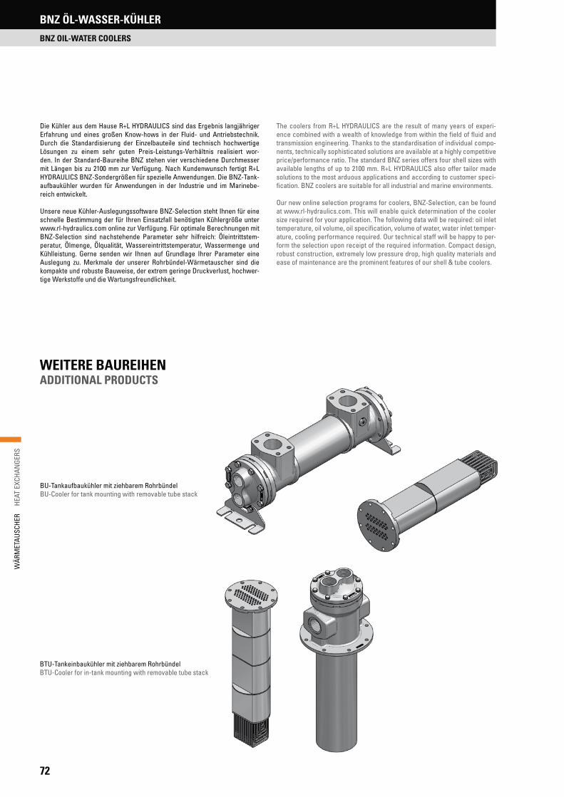
72
WÄR
MET
AUSC
HER
H
EAT
EXCH
ANGE
RSBNZ ÖL-WASSER-KÜHLER
BNZ OIL-WATER COOLERS
Die Kühler aus dem Hause R+L HYDRAULICS sind das Ergebnis langjähriger Erfahrung und eines großen Know-hows in der Fluid- und Antriebstechnik. Durch die Standardisierung der Einzelbauteile sind technisch hochwertige Lösungen zu einem sehr guten Preis-Leistungs-Verhältnis realisiert wor-den. In der Standard-Baureihe BNZ stehen vier verschiedene Durchmesser mit Längen bis zu 2100 mm zur Verfügung. Nach Kundenwunsch fertigt R+L HYDRAULICS BNZ-Sondergrößen für spezielle Anwendungen. Die BNZ-Tank-aufbaukühler wurden für Anwendungen in der Industrie und im Marinebe-reich entwickelt.
Unsere neue Kühler-Auslegungssoftware BNZ-Selection steht Ihnen für eine schnelle Bestimmung der für Ihren Einsatzfall benötigten Kühlergröße unter www.rl-hydraulics.com online zur Verfügung. Für optimale Berechnungen mit BNZ-Selection sind nachstehende Parameter sehr hilfreich: Öleintrittstem-peratur, Ölmenge, Ölqualität, Wassereintrittstemperatur, Wassermenge und Kühlleistung. Gerne senden wir Ihnen auf Grundlage Ihrer Parameter eine Auslegung zu. Merkmale der unserer Rohrbündel-Wärmetauscher sind die kompakte und robuste Bauweise, der extrem geringe Druckverlust, hochwer-tige Werkstoffe und die Wartungsfreundlichkeit.
The coolers from R+L HYDRAULICS are the result of many years of experi-ence combined with a wealth of knowledge from within the field of fluid and transmission engineering. Thanks to the standardisation of individual compo-nents, technically sophisticated solutions are available at a highly competitive price/performance ratio. The standard BNZ series offers four shell sizes with available lengths of up to 2100 mm. R+L HYDRAULICS also offer tailor made solutions to the most arduous applications and according to customer speci-fication. BNZ coolers are suitable for all industrial and marine environments.
Our new online selection programs for coolers, BNZ-Selection, can be found at www.rl-hydraulics.com. This will enable quick determination of the cooler size required for your application. The following data will be required: oil inlet temperature, oil volume, oil specification, volume of water, water inlet temper-ature, cooling performance required. Our technical staff will be happy to per-form the selection upon receipt of the required information. Compact design, robust construction, extremely low pressure drop, high quality materials and ease of maintenance are the prominent features of our shell & tube coolers.
WEITERE BAUREIHENADDITIONAL PRODUCTS
BU-Tankaufbaukühler mit ziehbarem RohrbündelBU-Cooler for tank mounting with removable tube stack
BTU-Tankeinbaukühler mit ziehbarem RohrbündelBTU-Cooler for in-tank mounting with removable tube stack
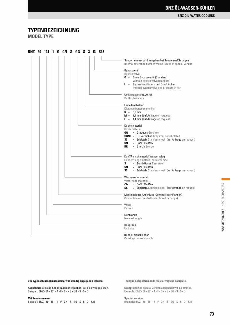
73
WÄR
MET
AUSC
HER
HE
AT E
XCHA
NGE
RS
BNZ ÖL-WASSER-KÜHLER
BNZ OIL-WATER COOLERS
Sondernummer wird vergeben bei SonderausführungenInternal reference number will be issued at special version
BypassventilBypass valveO = Ohne Bypassventil (Standard) Without bypass valve (standard) I = Bypassventil intern und Druck in bar Internal bypass valve and pressure in bar
Umlenksegmente/AnzahlBaffles/Numbers
LamellenabstandDistance between the finsS = 0,8 mmM = 1,1 mm (auf Anfrage on request)L = 1,4 mm (auf Anfrage on request)
DeckelmaterialCover materialGG = Grauguss Grey iron GGNI = GG vernickelt Grey iron; nickel-platedSS = Edelstahl Stainless steel (auf Anfrage on request)CN = CuNi10Fe1MNBR = Bronze Bronze
Kopf/Flanschmaterial WasserseitigHeader/flange material on water-side S = Stahl (Guss) Cast steel CN = CuNi10Fe1Mn SS = Edelstahl Stainless steel (auf Anfrage on request)
Wasserrohrmaterial Water-tube material CN = CuNi10Fe1MnSS = Edelstahl/Stainless steel (auf Anfrage on request)
Mantelseitiger Anschluss (Gewinde oder Flansch)Connection on the shell side (thread or flange)
WegePasses
NennlängeNominal length
BaugrößeUnit size
Bündel nicht ziehbarCartridge non-removable
TYPENBEZEICHNUNGMODEL TYPE
Der Typenschlüssel muss immer vollständig angegeben werden.
Ausnahme: Ist keine Sondernummer vergeben, wird sie weggelassen. Beispiel: BNZ - 80 - 361 - 4 - F - CN - S - GG - S - 5 - O
Mit SondernummerBeispiel: BNZ - 80 - 361 - 4 - F - CN - S - GG - S - 5 - O - S25
The type designation code must always be complete.
Exception: if no special version assigned it will be omitted.Example: BNZ - 80 - 361 - 4 - F - CN - S - GG - S - 5 - O
Special versionExample: BNZ - 80 - 361 - 4 - F - CN - S - GG - S - 5 - O - S25
BNZ - 60 - 131 - 1 - G - CN - S - GG - S - 3 - I3 - S13

74
WÄR
MET
AUSC
HER
H
EAT
EXCH
ANGE
RS
U
KL
M
KL
R
M
NO
P
S S
T
NO
P
R
B CDG G
JI
AEF
KL
M
U
S S
T
NO
P
R
H
AEF
B CDG G
JI
nur für BNZ 60only for BNZ 60
KL
MKL
M
NO
P
U
S S
T
NO
P
B CDG G
JI
AEF
nur für BNZ 60only for BNZ 60
2-WEGE2-PASS
1-WEG1-PASS
4-WEGE4-PASS
BNZ ÖL-WASSER-KÜHLER
BNZ OIL-WATER COOLERS
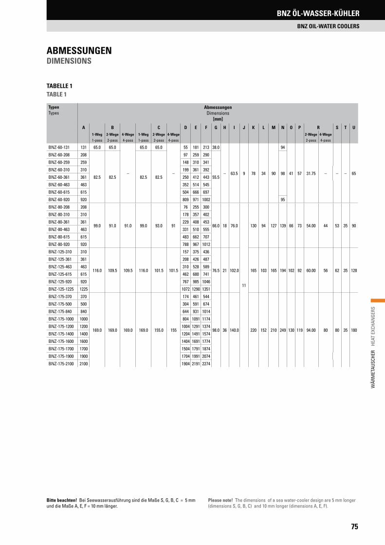
75
WÄR
MET
AUSC
HER
HE
AT E
XCHA
NGE
RS
ABMESSUNGENDIMENSIONS
TypenTypes
Abmessungen Dimensions
[mm]
A B C D E F G H I J K L M N O P R S T U1-Weg1-pass
2-Wege2-pass
4-Wege4-pass
1-Weg1-pass
2-Wege2-pass
4-Wege4-pass
2-Wege2-pass
4-Wege4-pass
BNZ-60-131 131 65.0 65.0
–
65.0 65.0
–
55 181 213 38.0
– 63.5 9 78 34 90
94
41 57 31.75 – – – 65
BNZ-60-208 208
82.5 82.5 82.5 82.5
97 259 290
55.598
BNZ-60-259 259 148 310 341
BNZ-60-310 310 199 361 392
BNZ-60-361 361 250 412 443
BNZ-60-463 463 352 514 545
BNZ-60-615 615 504 666 697
BNZ-60-920 920 809 971 1002 95
BNZ-80-208 208
99.0 91.0 91.0 99.0 93.0 91
76 255 300
66.0 18 76.0
11
130 94 127 139 66 73 54.00 44 53 35 90
BNZ-80-310 310 178 357 402
BNZ-80-361 361 229 408 453
BNZ-80-463 463 331 510 555
BNZ-80-615 615 483 662 707
BNZ-80-920 920 788 967 1012
BNZ-125-310 310
116.0 109.5 109.5 116.0 101.5 101.5
157 375 436
76.5 21 102.0 165 103 165 194 102 92 60.00 56 62 35 128
BNZ-125-361 361 208 426 487
BNZ-125-463 463 310 528 589
BNZ-125-615 615 462 680 741
BNZ-125-920 920 767 985 1046
BNZ-125-1225 1225 1072 1290 1351
BNZ-175-370 370
169.0 169.0 169.0 169.0 155.0 155
174 461 544
98.0 36 140.0 220 152 210 249 130 119 94.00 80 80 35 180
BNZ-175-500 500 304 591 674
BNZ-175-840 840 644 931 1014
BNZ-175-1000 1000 804 1091 1174
BNZ-175-1200 1200 1004 1291 1374
BNZ-175-1400 1400 1204 1491 1574
BNZ-175-1600 1600 1404 1691 1774
BNZ-175-1700 1700 1504 1791 1874
BNZ-175-1900 1900 1704 1991 2074
BNZ-175-2100 2100 1904 2191 2274
TABELLE 1TABLE 1
Bitte beachten! Bei Seewasserausführung sind die Maße S, G, B, C = 5 mm und die Maße A, E, F = 10 mm länger.
Please note! The dimensions of a sea water-cooler design are 5 mm longer (dimensions S, G, B, C) and 10 mm longer (dimensions A, E, F).
BNZ ÖL-WASSER-KÜHLER
BNZ OIL-WATER COOLERS

76
WÄR
MET
AUSC
HER
H
EAT
EXCH
ANGE
RS
TABELLE 2TABLE 2
TypenTypes
Wärmeaustausch-fläche
Heat exchange surface area
[m2]
ÖlanschlussOil port
WasseranschlüsseWater connection
Ablass-SchraubeDrain plug
(S)
Anzahl der Umlenk-
segmente Number of
bafflesStandardStandard
OptionalOptional
Ablass-SchraubeDrain plug
(S)
MessanschlussTest port
(T)
1-Weg1-pass
2-Wege2-pass
4-Wege4-pass
BNZ-60-131 0.32 G ½“
–– – G ¾“ G 3/8“ – G 1/8“
1BNZ-60-208 0.57
G ¾“
BNZ-60-259 0.73 3BNZ-60-310 0.90 1BNZ-60-361 1.06
3BNZ-60-463 1.38BNZ-60-615 1.86
5BNZ-60-920 2.83BNZ-80-208 1.11
G 1½“ G ¼“ G ¼“
G 1¼“ G 1“ G ½“
G ¼“
1BNZ-80-310 1.74
SAE 1½“BNZ-80-361 2.04
3BNZ-80-463 2.67BNZ-80-615 3.60BNZ-80-920 5.47 5BNZ-125-310 3.72
SAE 2“ G ½“ G 1¼“ G ¾“
1BNZ-125-361 4.35
3BNZ-125-463 5.71BNZ-125-615 7.71BNZ-125-920 11.72 3, 5BNZ-125-1225 15.71 3, 5, 7BNZ-175-370 8.54
SAE 3½" – G ½" G ½" SAE 3½" SAE 2" SAE 1¼" G ½"
1BNZ-175-500 11.73 1, 3BNZ-175-840 20.19 3, 5BNZ-175-1000 24.18 3, 5, 7BNZ-175-1200 29.18 3, 5, 7BNZ-175-1400 34.13 5, 7, 9BNZ-175-1600 39.12 5, 7, 9BNZ-175-1700 41.62 3, 7, 11BNZ-175-1900 46.61 3, 7, 11BNZ-175-2100 51.56 3, 7, 11
Die Längenmaße können sich aus produktionstechnischen Gründen um ± 2 mm ändern.Length measurements may vary for production engineering reasons by ± 2 mm.
ABMESSUNGENDIMENSIONS
BNZ ÖL-WASSER-KÜHLER
BNZ OIL-WATER COOLERS

77
WÄR
MET
AUSC
HER
HE
AT E
XCHA
NGE
RS
KomponentenComponents
Standard-KühlerStandard-Cooler
Seewasser-KühlerSeewater-Cooler
Optional (auf Anfrage)Optional (on request)
RohreTubes
CuNi 90/10CuNi 90/10
CuNi 90/10CuNi 90/10
Kupfer/Edelstahl Copper/Stainless steel
Mantel, Umlenkblech, Befestigungswinkel, BypassventilShell, guide plate, mounting bracket, bypass valve
StahlSteel
StahlSteel
DeckelEnd cover
Grauguss GG25Cast Iron GG25
chem. vernickeltchemically nickel-plated
EdelstahlStainless steel
BronzeBronze
LamellenFins
AluminiumAluminium
AluminiumAluminium
Kupfer/EdelstahlCopper/Stainless steel
RohrbodenTube sheet
StahlSteel
Stahl mit CuNi-Endplatte 90/10Steel with CuNi end plate 90/10
EdelstahlStainless steel
DichtungenGaskets
Flachdichtung C4400Flat Gasket C4400
MATERIALIEN MATERIALS
TECHNISCHE DATENTECHNICAL DATA
1) Die maximale Betriebstemperatur beträgt 95 °C (höhere Temperatur auf Anfrage)
2) Der maximale Betriebsdruck ist mantelseitig 40 bar und rohrseitig 16 bar
3) Die maximalen Durchflussmengen [l/min] siehe Tabelle 4
1) Maximum operating temperature 95 °C (higher temperatures on request)
2) Maximum operating pressure 40 bar on shell side and 16 bar on tube side
3) Maximum flow rate volumes [l/min] see table 4
MAXIMALE DURCHFLUSSMENGENMAXIMUM FLOW RATE VOLUMES
BNZ/BU/BTUBaureihenProduct Series
ÖlOil
Mantel Shell
[l/min]
BNZWasserWater [l/min]
1-Weg1-pass
2-Wege2-pass
4-Wege4-pass
Cu CuNi SS Cu CuNi SS Cu CuNi SS
DN 60 75 47 70 105 23 35 54 – – –
DN 80 G/F 225 90 135 202 45 67 100 22 34 51
DN 125 G 330 206 310 465 103 155 232 51 77 115
DN 125 F 400 206 310 465 103 155 232 51 77 115
DN 175 850 410 614 921 205 307 460 102 154 230
G = Gewinde; F = Flansch (Größen siehe Seite 75)
Bei einer Kühlung mit Seewasser wird die Wassermenge nach unten korri-giert. Bitte wenden Sie sich an unsere technische Abteilung.
Achtung! – Bitte beachten Sie vor dem Einbau die Wartungs- und Bedie-nungsanleitung. Unsachgemäßer Einbau kann zur Beschädigung des Kühlers führen!
G = BSP; F = flange (sizes see page 75)
For sea water application, the water volume should be reduced. Please con-tact our technical dept.
Caution! – Please study the maintenance and operating instructions before installation of the heat exchanger. Incorrect installation can cause damage to the cooler!
TABELLE 3TABLE 3
TABELLE 4TABLE 4
BNZ ÖL-WASSER-KÜHLER
BNZ OIL-WATER COOLERS

78
WÄR
MET
AUSC
HER
H
EAT
EXCH
ANGE
RSPK PLATTENWÄRMETAUSCHER
PK PLATE HEAT EXCHANGERS
PK PLATTENWÄRMETAUSCHERPK PLATE HEAT EXCHANGERS
Geräteanschlüsse: F1 Primär – Ein F2 Primär – Aus F3 Sekundär – Aus F4 Sekundär – EinPlattenmaterial: Edelstahl (1.4404)Lot: KupferBetriebsdruck max.: 30 bar (Nickel 16 bar)Temperatur max.: ±195 °C
Connection ports: F1 Primary – On F2 Primary – Off F3 Secondary – Off F4 Secondary – OnPlate material: Stainless steel (AISI316L)Solder: CopperOperating pressure max.: 30 bar (nickel 16 bar)Operating temperature max.: ±195 °C
TECHNISCHE DATEN TECHNICAL DATA

79
WÄR
MET
AUSC
HER
HE
AT E
XCHA
NGE
RS
PK PLATTENWÄRMETAUSCHER
PK PLATE HEAT EXCHANGERS
ABMESSUNGEN DIMENSIONS
TypenTypes
A[mm]
B [mm]
C[mm]
D[mm]
F[mm]
PK-10 74 40 204 170 8.0 + 2.23 x n
PK-2090
43
231 182 10.0 + 2.24 x n
PK-220 328 279 10.0 + 2.22 x n
PK-240 91 464 415 10.0 + 2.20 x n
PK-30
124 73
173 120 10.0 + 2.22 x n
PK-40 335 281 9.5 + 2.24 x n
PK-50
532
478 9.5 + 2.23 x n
PK-70L/M
271
200 460 11.0 + 2.25 x n
PK-80 161 421 11.5 + 2.34 x n
PK-90 161 802 690 11.3 + 2.31 x n
* Das Maß „F“ ergibt sich bei PK-10 bis PK-100 durch die Plattenzahl und den Wert Kopfplatte + Fußplatte. n = Anzahl der Platten
** Bodenkonsole BK 35 für PK-30 bis PK-50 und Bodenkonsole BK 79 für PK-70 bis PK-90
* The dimension „F“ results for PK-10 to PK-100 from the number of plates and the value cover plate + base plate. n = number of plates
** Floorbracket BK 35 for PK-30 up to PK-50 and Floorbracket BK 79 for PK-70 up to PK-90
BaugrößeSize
PlattenanzahlNo. of plates
InnengewindeInternal thread
I
SchlüsselweiteKey width
SW
AußengewindeExternal thread
A
FlanschFlange
F
PK-10 8, 10, 14, 20, 24, 30, 34, 40, 44, 50 G ½“ – G ½“, G ¾“
–
PK-20 8, 10, 14, 20, 24, 30, 34, 40, 44, 50 G ½“, G ¾“ –, SW 32 G ½“, G ¾“, G 1“
PK-220PK-240 8, 10, 14, 20, 24, 30, 34, 40, 44, 50 G ½“, G ¾“ –, SW 32 G ½“, G ¾“, G 1“
PK-30 8, 10, 14, 20, 24, 30, 34, 40, 44, 50 G ½“ bis G 1“ SW 36, SW 46 G ¾“, G 1“, G 1¼“
PK-40PK-50
8, 10, 14, 20, 24, 30, 34, 40, 44, 50, 60, 70, 80, 90, 100 G ¾“ bis G 1“ SW 36, SW 46 G ¾“, G 1“, G 1¼“
PK-70L/70M 20, 24, 30, 34, 40, 44, 50, 60, 70, 80, 90, 100, 110, 120, 130, 140, 150 G 1½“ SW 55 G 1½“, G 2“ DN 40
DN 50
PK-80PK-90
20, 24, 30, 34, 40, 44, 50, 60, 70, 80, 90, 100, 110, 120, 130, 140, 150, ..., 260 G 2½“ SW 85 G 2“, G 2½“ DN 65
DN 80
PK-100 50, 60, 70, 80, 90, 100, 110, 120, 130, 140, 150, 160, 170, 180, 190, 200, ..., 300
auf Anfrageon request
auf Anfrageon request
auf Anfrageon request DN 65, DN 80, DN 100*
*Spezial / *SpecialWeitere Anschlüsse auf Anfrage / Other connection sizes on request

80
WÄR
MET
AUSC
HER
H
EAT
EXCH
ANGE
RSPK PLATTENWÄRMETAUSCHER
PK PLATE HEAT EXCHANGERS
TYPENBEZEICHNUNG MODEL TYPE
TransporthakenTransport hooks
H = Halterung BWK = Boden-Wand-KonsoleH = Bracket BWK = Floor-Wall-Console
Nickel gelötet (auf Anfrage) Nickel soldered (on request)
Gewindegröße Thread size
Gewindeart A = Außengewinde I = Innengewinde F = FlanschType of thread A = External thread I = Internal thread F = Flange
Plattenanzahl Number of plates
Baugröße Size
Plattenwärmetauscher Plate heat exchanger
HALTERUNGEN BRACKETS
PK-30 – PK-50
PK-30 – PK-50Boden-Wand-KonsoleFloor-Wall-Console
PK-70 – PK-90Halterung und TransporthakenBracket and Transport hooks
PK - 10 - 20 - I - G1 - N - H - TH
Plattenwärme-tauscherHeat exchanger
Art der HalterungBracket Type
BezeichnungDesignation
PK-30 – PK-50 FußhalterungBracket
Fußhalterung für Bracket forPK-30, PK-40 und PK-50
PK-30 – PK-50Boden-Wand-
KonsoleFloor-Wall-Console
Boden-Wand-Konsole für Floor-Wall-Console for PK-30, PK-40 und PK-50
PK-70 – PK-90 FußhalterungBracket
Fußhalterung für Bracket for PK-70, PK-80 und PK-90
PK-70 – PK-90 TransporthakenTransport hooks
Transporthaken für Transport hooks for
PK-70, PK-80 und PK-90
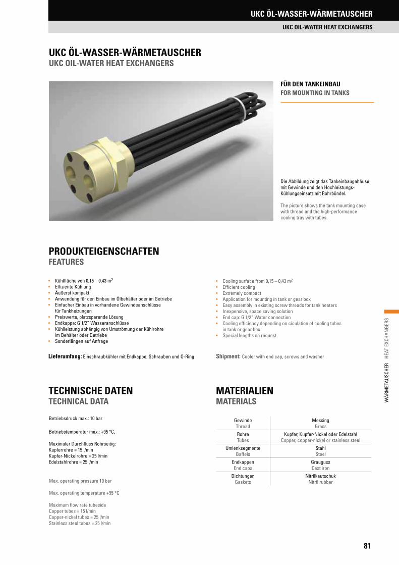
81
WÄR
MET
AUSC
HER
HE
AT E
XCHA
NGE
RS
• Kühlfläche von 0,15 – 0,43 m2
• Effiziente Kühlung• Äußerst kompakt• Anwendung für den Einbau im Ölbehälter oder im Getriebe• Einfacher Einbau in vorhandene Gewindeanschlüsse
für Tankheizungen• Preiswerte, platzsparende Lösung• Endkappe: G 1/2” Wasseranschlüsse• Kühlleistung abhängig von Umströmung der Kühlrohre
im Behälter oder Getriebe• Sonderlängen auf Anfrage
• Cooling surface from 0,15 – 0,43 m2
• Efficient cooling• Extremely compact• Application for mounting in tank or gear box• Easy assembly in existing screw threads for tank heaters• Inexpensive, space saving solution• End cap: G 1/2” Water connection• Cooling efficiency depending on ciculation of cooling tubes
in tank or gear box• Special lengths on request
PRODUKTEIGENSCHAFTENFEATURES
TECHNISCHE DATENTECHNICAL DATA
Betriebsdruck max.: 10 bar
Betriebstemperatur max.: +95 °C,
Maximaler Durchfluss Rohrseitig:Kupferrohre = 15 l/minKupfer-Nickelrohre = 25 l/minEdelstahlrohre = 25 l/min
Die Abbildung zeigt das Tankeinbaugehäuse mit Gewinde und den Hochleistungs- Kühlungseinsatz mit Rohrbündel.
The picture shows the tank mounting case with thread and the high-performance cooling tray with tubes.
Lieferumfang: Einschraubkühler mit Endkappe, Schrauben und O-Ring Shipment: Cooler with end cap, screws and washer
FÜR DEN TANKEINBAUFOR MOUNTING IN TANKS
Max. operating pressure 10 bar
Max. operating temperature +95 °C
Maximum flow rate tubesideCopper tubes = 15 l/minCopper-nickel tubes = 25 l/minStainless steel tubes = 25 l/min
MATERIALIENMATERIALS
GewindeThread
MessingBrass
Rohre Tubes
Kupfer, Kupfer-Nickel oder Edelstahl Copper, copper-nickel or stainless steel
UmlenksegmenteBaffels
StahlSteel
EndkappenEnd caps
GraugussCast iron
DichtungenGaskets
NitrilkautschukNitril rubber
UKC ÖL-WASSER-WÄRMETAUSCHER
UKC OIL-WATER HEAT EXCHANGERS
UKC ÖL-WASSER-WÄRMETAUSCHERUKC OIL-WATER HEAT EXCHANGERS

82
WÄR
MET
AUSC
HER
H
EAT
EXCH
ANGE
RSUKC ÖL-WASSER-WÄRMETAUSCHER
UKC OIL-WATER HEAT EXCHANGERS
ABMESSUNGENDIMENSIONS
TypType
L[mm]
x 11 190
x 12 550
x 13 580
x 14 600
x 15 630
x 16 640
x 17 690
x 18 705
x 19 780
x 20 805
x 21 950
x 22 1400
CU = Rohre Kupfer Tubes copper
CN = Rohre Kupfer/Nickel (90:10) Tubes copper-nickel (90:10)
SS = Rohre Edelstahl (1.4571) Tubes stainless steel (1.4571)
Längenmaß (siehe Tabelle)Linear dimension (see chart)
Gewindeanschlußgröße: G 1,5” = 1,5, G 2” = 2Threaded connection size: G 1,5” = 1.5, G 2” = 2“
U-Rohr KühleinsatzU-tube cooling device
TYPENBEZEICHNUNGMODEL TYPE
UKC – G 1,5“ – 550 – CU
15 +0,2 181,5 x 45°
Ø 80
-0,5
CA.100 CA.100 CA.100
Ø 74
±0,5
R ½“
35
Ø 56
G
2“
47 ”L“
UKC-G 1.5
15 +0,2 181,5 x 45°
Ø 80
-0,5
CA.100 CA.100 CA.100
Ø 74
±0,5
R ½“
35
Ø 56
G
2“
47 ”L“
UKC-G 2 TypType
L[mm]
xx 1 550
xx 2 840
xx 3 850
xx 4 930
xx 5 940
xx 6 1030
xx 7 1070
xx 8 1085
xx 9 1170
xx 10 1190
83
WÄR
MET
AUSC
HER
HE
AT E
XCHA
NGE
RS
NOTIZENNOTES

EINFÜHRUNG KUPPLUNGEN
INTRODUCTION COUPLINGS
84
SPIDEX® – die elastische KupplungDENTEX® / DENTEX® FL– die flexible KupplungSPIDEX® – the elastic couplingDENTEX® / DENTEX® FL– the flexible coupling
EINFÜHRUNG KUPPLUNGEN
INTRODUCTION COUPLINGS
85
KUPP
LUN
GEN
C
OUPL
INGS
SPIDEX® – DIE ELASTISCHE KUPPLUNG 86SPIDEX® – THE ELASTIC COUPLING
DENTEX®/DENTEX® FL – DIE FLEXIBLE KUPPLUNG 101DENTEX®/DENTEX® FL – THE FLEXIBLE COUPLING
TORSIONSKUPPLUNGEN LF/LK 108TORSIONAL COUPLINGS LF/LK
HERCUFLEX – DIE ZAHNKUPPLUNG 138HERCUFLEX – THE GEAR COUPLING
LAMELLENKUPPLUNGEN 159DISC COUPLINGS
KUPPLUNGEN FÜR DEN ATEX-BEREICH 173COUPLINGS FOR ATEX ZONES
KUPPLUNGENCOUPLINGS

86
KUPP
LUN
GEN
C
OUPL
INGS
SPIDEX® – DIE ELASTISCHE KUPPLUNG
SPIDEX® – THE ELASTIC COUPLING
FUNKTIONSWEISETECHNICAL DESCRIPTION
Elastic couplings reduce intermittent short-period torsional shocks by briefly storing part of this shock energy elastically. Any degree of uneven move-ment and torque transference is consequently reduced. Elastic couplings suppress body resonance and therefore contribute to noise reduction. The elastic SPIDEX® coupling transmits the torque without the risk of breakdown and backlash-free. The convex generated profiled tooth crown, see Fig. 1, al-lows compensation of radial and angular displacements of the two connected shafts. It consists of a thermoplastic polyurethane elastomer that is loaded exclusively under pressure, designed for high abrasion resistance and elas-ticity, has good damping characteristics, is resistant to oils, greases, many solvents, atmospheric effects and ozone, as well as having a good resistance to hydrolysis in tropical conditions.
The operating temperature range is between -40 °C and +100 °C. Short tem-perature peaks up to +120 °C are admissible. For ambient temperatures above +100 °C contact R+L HYDRAULICS.
The standard hardness of the spider is 92° Shore A. For higher torques, a spi-der of 95° to 98° Shore A can be used, and for very high torques a spider with 64° Shore D, which is extremely hard and has a low damping effect. As Figures 1 and 2 show, the convex rim of the tooth absorbs a higher proportion of de-formation energy as deformation increases (see p. 87). The torsional stiffness value CT of the tooth crown increases with the torsional angle. Consequently, the coupling is relatively soft under small load conditions and becomes pro-gressively harder as the torque increases. This causes a progressive torsion curve, as shown in Fig. 3. The dynamic torsion curve has an insignificantly steeper course.
The damping energy shown in Fig. 3 results in the damping of torque shocks as shown in Fig. 4.
The special advantage of the progressive torsion characteristic is the reso-nance suppression achieved by the SPIDEX® coupling, as the critical reso-nance speed depends on the torsional stiffness CT (see Fig. 5). Hence, dif-ferent load conditions change the resonance behaviour of the system, which may reduce the risk of resonances.
The progressive curve therefore mainly protects the coupling against inadmis-sible overstressing. Furthermore, the torsional rigidity CT of the spider can be influenced by the choice of an appropriate Shore hardness material. A larger Shore hardness moves the resonance speed higher, and a lower Shore hard-ness moves resonance speed into a lower range. If in doubt, we recommend a calculation of the system’s dynamics by using the moments of inertia of the driving and driven sides.
SPIDEX® – DIE ELASTISCHE KUPPLUNGSPIDEX® – THE ELASTIC COUPLING
Elastische Kupplungen sind in der Lage, kurzzeitige Drehmomentstöße durch zeitweilige elastische Speicherung eines Teiles der Stoßenergie zu mildern. Der Ungleichförmigkeitsgrad der Bewegungs- und Drehmomentübertra-gung wird somit kleiner. Elastische Kupplungen dämpfen den Körperschall und tragen somit zur Geräuschminderung bei. Die elastische SPIDEX®-Kupplung überträgt das Drehmoment formschlüssig und durchschlagsicher. Der ballig profilierte Evolventenzahn (Abb. 1) gestattet den Ausgleich von Radial- und Winkelverlagerungen der zu verbindenden Wellen. Er besteht aus einem thermoplastischen Polyurethan-Elastomer, ist ausschließlich auf Druck belastet und zeichnet sich darüber hinaus durch hohe Verschleißfestigkeit und Elastizität, gute Dämpfungseigenschaften und gute Beständigkeit gegen Öle, Fette, viele Lösemittel, Witterungseinflüsse und Ozon aus. Hinzu kommt eine gute Hydrolyse- und Tropenbeständigkeit.
Die Einsatztemperaturen liegen zwischen -40 °C und +100 °C in der Standar-dausführung. Kurzzeitige Temperaturspitzen bis +120 °C sind zulässig. Für Einsatztemperaturen dauerhaft über +100 °C wenden Sie sich bitte an R+L HYDRAULICS.
Die Standardhärte des Zahnkranzes beträgt 92° Shore A. Für höhere Drehmo-mente können auch Zähnkränze mit 95° und 98° Shore A und für sehr hohe Drehmomente ein Zahnkranz mit 64° Shore D eingesetzt werden, dieser ist sehr hart und hat eine geringe Dämpfung. Durch die aus Abb. 1 und Abb. 2 zu ersehende Balligkeit nehmen die Zähne des Zahnkranzes mit zunehmender Verformung eine überproportional wachsende Verformungsenergie auf (Seite 87). Der Wert der Federsteife CT des Zahnkranzes nimmt mit Vergrößerung des relativen Drehwinkels zu. Folglich arbeitet die Kupplung bei geringer Dreh-momentübertragung relativ weich und mit zunehmendem Drehmoment immer härter. Hieraus ergibt sich eine progressive Federkennlinie gemäß Abb. 3. Die dynamische Federkennlinie hat einen geringfügig steileren Verlauf.
Die in Abb. 3 dargestellte Dämpfungsarbeit bewirkt die in Abb. 4 ersichtliche Dämpfung von Drehmomentstößen.
Ein besonderer Vorteil der progressiven Federkennlinie liegt im Resonanzver-halten der SPIDEX®-Kupplung. Da die kritische Resonanzdrehzahl abhängig von der Federsteife CT ist, letztere sich jedoch mit Verschiebung des Arbeits-punktes ändert, ergibt sich eine Verstimmung des Systems gemäß Abb. 5, wel-che die Gefahr des Aufschaukelns verringert.
Die progressive Kennlinie schützt somit vor allem die Kupplung gegen unzu-lässige Überbeanspruchung. Darüber hinaus kann die Federsteife CT durch eine entsprechende Wahl der Shorehärte beeinflusst werden. Eine größere Shorehärte verlagert die Resonanzdrehzahl in einen höheren, eine niedrigere Shorehärte in einen niedrigeren Bereich. Im Zweifelsfalle empfehlen wir eine Berechnung des Systems mittels der antriebs- und lastseitigen Massenträg-heitsmomente.
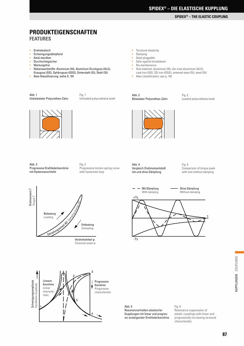
87
KUPP
LUN
GEN
C
OUPL
INGS
SPIDEX® – DIE ELASTISCHE KUPPLUNG
SPIDEX® – THE ELASTIC COUPLING
Abb. 1Unbelasteter Polyurethan-Zahn
Fig. 1Unloaded polyurethane tooth
Abb. 2Belasteter Polyurethan-Zahn
Fig. 2Loaded polyurethane tooth
Abb. 3Progressive Drehfederkennlinie mit Hystereseschleife
Fig. 3Progressive torsion spring curve with hysteresis loop
Abb. 4Vergleich Drehmomentstoß mit und ohne Dämpfung
Fig. 4Comparison of torque peak with and without damping
Abb. 5Resonanzverhalten elastischer Kupplungen mit linear und progres-siv ansteigender Drehfederkennlinie
Fig. 5Resonance suppression of elastic couplings with linear and progressively increasing torsional characteristic
Dreh
mom
ent T
Torq
ue T
BelastungLoading
Verdrehwinkel φTorsional angle φ
EntlastungUnloading
Dämpfungsarbeit A
D Dam
ping e
nerg
y AD
Mit DämpfungWith damping
Ohne DämpfungWithout damping
1
23
4
5
Schw
ingu
ngsa
mpl
itude
Osci
llatio
n am
plitu
de
Lineare KennlinieLinearcharacte-ristic
ProgressiveKennlinieProgressivecharacteristic
• Drehelastisch• Schwingungsdämpfend• Axial steckbar• Durchschlagsicher• Wartungsfrei• Nabenwerkstoffe: Aluminium (Al), Aluminium Druckguss (ALU),
Grauguss (GG), Sphäroguss (GGG), Sinterstahl (Si), Stahl (St)• Atex-Klassifizierung: siehe S. 181
PRODUKTEIGENSCHAFTENFEATURES
• Torsional elasticity• Damping• Axial pluggable• Safe against breakdown• No maintenance• Hub material: aluminium (Al), die-cast aluminium (ALU),
cast iron (GG), SG iron (GGG), sintered steel (Si), steel (St)• Atex classification: see p. 181

88
KUPP
LUN
GEN
C
OUPL
INGS
SPIDEX® – DIE ELASTISCHE KUPPLUNG
SPIDEX® – THE ELASTIC COUPLING
Schritt 1: Bestimmung des Nenndrehmoments Ihrer Anwendung:
TN [Nm] =
P[kW] x 9550
n [1/min]
Schritt 2: Berechnung des Betriebsfaktors Ihrer Anwendung mit der Tabelle auf Seite 89. Der Gesamtbetriebsfaktor (K) ergibt sich aus: K = K1 x K2 x K3
Schritt 3: Berechnung des konstruktiven Drehmoments (TNK) Ihrer Anwendung: Konstruktives Drehmoment (TNK) = Nenndrehmoment (TN) x Betriebsfaktor (K).
Schritt 4: Unter Verwendung der Elastomer-Leistungsdatentabellen auf der Seite 93 den Urethan-Shore-Härtegrad auswählen, der am besten den relativen Dämpfungsanforderungen Ihrer Anwen-dung entspricht.
Schritt 5: Finden Sie als nächstes die Spalten, in denen die Werte TKN und TKmax in Nm gelistet sind und vergleichen Sie diese mit dem Wert TNK für Ihre Anwendung. Stellen Sie sicher, dass die Werte des Zahnkranzes größer als die Anwendungswerte sind.
TKN & TKmax > TNK
Schritt 6: Nachdem die Größe unter Verwendung der Drehmomentwerte ausgewählt ist, stellen Sie mit Hilfe der Tabelle auf Seite 91 sicher, dass der erforderliche Bohrungsdurchmesser in die Kupplung passt.
Schritt 7: Überprüfen Sie sorgfältig das Gesamtmaß der Kupplung, um zu gewährleisten, dass die Kupplung in den Einbauraum passt.
AUSWAHLPROZESS ZUR GRÖSSENBESTIMMUNGSELECTION PROCESS FOR SIZING DETERMINATION
TN [Nm] Nenndrehmoment der Anwendung Nominal torque of the application
TKmax [Nm] Maximales Drehmoment der Kupplung Maximum torque of the coupling
P [kW] Leistung in Kilowatt Power in kilowatts
n [1/min] Umdrehungen pro Minute Revolutions per minute
Nm Newtonmeter Newton meters
TNK [Nm] Konstruktives Drehmoment der Anwendung Constructional torque of the application
TKW [Nm] Wechseldrehmoment Alternating torque
K Betriebsfaktor Application service factor
DEFINITION DER BEGRIFFEDEFINITION OF TERMS
Bei dem vorliegenden Auswahlprozess handelt es sich um ein vereinfachtes Verfahren zur Größenbestimmung unserer SPIDEX® Kupplung. Für eine ge-nauere Auswahl ist die DIN 704 T2 anzuwenden. Die Welle-Nabe-Verbindung ist kundenseitig zu prüfen.
Step 1: Determine the nominal torque of your application:
TN [Nm] =
P[kW] x 9550
n [1/min]
Step 2: Calculate your application service factor using the charts on page 89.
The total service factor (K) will be: K = K1 x K2 x K3
Step 3: Calculate the design torque (TNK) of your application: Design torque (TNK) = nominal torque (TN) x service factor (K).
Step 4: Using the elastomer performance data charts on page 93, select the urethane shore hardness which best corresponds to your relative damping needs in the application.
Step 5: Next find the columns listing TKN and TKmax values listed in Nm and compare them against the TNK figure for your application. Make sure that the spider/coupling size values are larger than the application values.
TKN & TKmax > TNK
Step 6: Once the size has been selected using the torque values, check the table on page 91 to make sure the bore size needed will fit in the coupling.
Step 7: Double check the overall dimensions of the coupling to ensure that it will fit in the space allowed for the coupling in the application.
This process is a simplified procedure for determining the correct size when selecting one of our SPIDEX® couplings. Use DIN 704 T2 when making a pre-cise selection. The shaft-hub connection has to be checked by the customer.

89
KUPP
LUN
GEN
C
OUPL
INGS
SPIDEX® – DIE ELASTISCHE KUPPLUNG
SPIDEX® – THE ELASTIC COUPLING
Anläufe pro StundeStarts per hour 100 200 400 800
Betriebsfaktor K2Service factor K2 1.0 1.2 1.4 1.6
ANWENDUNGS-BETRIEBSFAKTORENAPPLICATION SERVICE FACTORS
K1
K2 – FÜR ANLÄUFE PRO STUNDEK2 – FOR STARTS PER HOUR
K3 – FÜR UMGEBUNGSTEMPERATURENK3 – FOR AMBIENT TEMPERATURE
Betriebsfaktor K1Application service factor K1
Gleichmäßiger Betrieb mit kleinen Beschleunigungsmassen. Hydraulik- und Zentrifugalpumpen, kleine Generatoren, Gebläse, Lüfter, Ventilatoren, Band-/Schraubenförderer. Uniform operation with small masses to be accelerated. Hydraulic and centrifugal pumps, light generators, blowers, fans, ventilators, belt/screw conveyors.
1.0
Gleichmäßiger Betrieb mit mittleren Beschleunigungsmassen. Blechbiegemaschinen, Holzbearbeitungsmaschinen, Walzwerke, Textilmaschinen, Mischer. Uniform operation with medium masses to be accelerated. Sheet metal bending machines, wood working machines, mills, textile machines, mixers.
1.2
Ungleichmäßiger Betrieb mit mittleren Beschleunigungsmassen. Rotierende Öfen, Druckpressen, Generatoren, Schredder, Wickelmaschinen, Spinnmaschinen, Pumpen für dickflüssige Fluide. Irregular operation with medium masses to be accelerated. Rotating ovens, printing presses, generators, shredders, winders, spinning machines, pumps for viscous fluids.
1.3
Ungleichmäßiger Betrieb und Stoßbelastungen mit mittleren Beschleunigungsmassen. Betonmischer, Fallhämmer, Seilbahnen, Papiermühlen, Kompressionspumpen, Propellerpumpen, Seilwinden, Zentrifugen. Irregular operation and shocks, with medium masses to be accelerated. Concrete mixers, drop hammers, cable cars, paper mills, compression pumps, propeller pumps, rope winders, centrifuges.
1.4
Ungleichmäßiger Betrieb und starke Stoßbelastungen mit großen Beschleunigungsmassen. Bagger, Hammermühlen, Kolbenpumpen, Pressen, Erdbohrmaschinen, Scheren, Schmiedepressen, Steinbrecher. Irregular operation and heavy shocks, with large masses to be accelerated. Excavators, hammer mills, piston pumps, presses, rotary boring machines, shears, forge presses, stone crushers.
1.6
Ungleichmäßiger Betrieb und sehr starke Stoßbelastungen mit sehr großen Beschleunigungsmassen. Kolbenkompressoren und Pumpen ohne Drehzahlregelung, schwere Walzensätze, Schweißmaschinen, Ziegelpressen, Steinbrecher.Irregular operation and very heavy shocks, with very large masses to be accelerated. Piston-type compressors and pumps without speed variations, heavy roller sets, welding machines, brick presses, stone crushers.
1.8
Zahnkranz TypInsert type
-50 °C -30 °C bis up to
+30 °C
+40 °C +50 °C +60 °C +70 ° C +80 °C +90 °C +100 °C +110 °C +120 °C
Standard – 1.0 1.2 1.3 1.4 1.55 1.8 2.2 – – –High Temperature 1.0 1.0 1.1 1.2 1.3 1.45 1.6 1.8 2.1 2.5 3.0
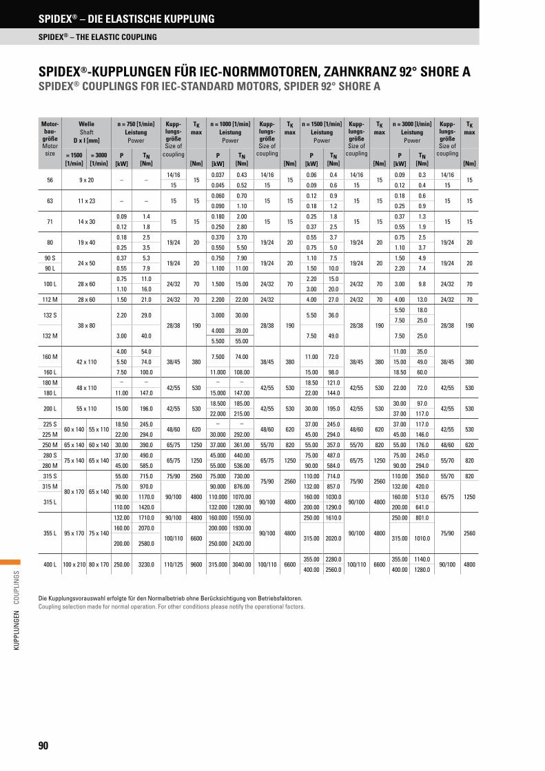
90
KUPP
LUN
GEN
C
OUPL
INGS
SPIDEX® – DIE ELASTISCHE KUPPLUNG
SPIDEX® – THE ELASTIC COUPLING
SPIDEX®-KUPPLUNGEN FÜR IEC-NORMMOTOREN, ZAHNKRANZ 92° SHORE ASPIDEX® COUPLINGS FOR IEC-STANDARD MOTORS, SPIDER 92° SHORE A
Die Kupplungsvorauswahl erfolgte für den Normalbetrieb ohne Berücksichtigung von Betriebsfaktoren.Coupling selection made for normal operation. For other conditions please notify the operational factors.
Motor-bau-
größeMotor
size
Welle Shaft
D x I [mm]
n = 750 [1/min] LeistungPower
Kupp-lungs-größe Size of
coupling
TKmax
n = 1000 [1/min] Leistung Power
Kupp-lungs-größeSize of
coupling
TKmax
n = 1500 [1/min] LeistungPower
Kupp-lungs-größeSize of
coupling
TKmax
n = 3000 [l/min] Leistung Power
Kupp-lungs-größeSize of
coupling
TKmax
= 1500 [1/min]
= 3000[1/min]
P [kW]
TN[Nm] [Nm]
P [kW]
TN [Nm] [Nm]
P [kW]
TN[Nm] [Nm]
P [kW]
TN [Nm] [Nm]
56 9 x 20 – –14/16
150.037 0.43 14/16
150.06 0.4 14/16
150.09 0.3 14/16
1515 0.045 0.52 15 0.09 0.6 15 0.12 0.4 15
63 11 x 23 – – 15 150.060 0.70
15 150.12 0.9
15 150.18 0.6
15 150.090 1.10 0.18 1.2 0.25 0.9
71 14 x 30 0.09 1.4
15 150.180 2.00
15 150.25 1.8
15 150.37 1.3
15 150.12 1.8 0.250 2.80 0.37 2.5 0.55 1.9
80 19 x 40 0.18 2.5
19/24 200.370 3.70
19/24 200.55 3.7
19/24 200.75 2.5
19/24 200.25 3.5 0.550 5.50 0.75 5.0 1.10 3.7
90 S 24 x 50
0.37 5.3 19/24 20
0.750 7.9019/24 20
1.10 7.519/24 20
1.50 4.919/24 20
90 L 0.55 7.9 1.100 11.00 1.50 10.0 2.20 7.4
100 L 28 x 60 0.75 11.0
24/32 70 1.500 15.00 24/32 702.20 15.0
24/32 70 3.00 9.8 24/32 701.10 16.0 3.00 20.0
112 M 28 x 60 1.50 21.0 24/32 70 2.200 22.00 24/32 4.00 27.0 24/32 70 4.00 13.0 24/32 70
132 S
38 x 80
2.20 29.0
28/38 190
3.000 30.00
28/38 190
5.50 36.0
28/38 190
5.50 18.0
28/38 1907.50 25.0
132 M 3.00 40.04.000 39.00
7.50 49.0 7.50 25.05.500 55.00
160 M 42 x 110
4.00 54.0
38/45 3807.500 74.00
38/45 38011.00 72.0
38/45 380
11.00 35.0
38/45 3805.50 74.0 15.00 49.0
160 L 7.50 100.0 11.000 108.00 15.00 98.0 18.50 60.0
180 M 48 x 110
– –42/55 530
– –42/55 530
18.50 121.042/55 530 22.00 72.0 42/55 530
180 L 11.00 147.0 15.000 147.00 22.00 144.0
200 L 55 x 110 15.00 196.0 42/55 53018.500 185.00
42/55 530 30.00 195.0 42/55 53030.00 97.0
42/55 53022.000 215.00 37.00 117.0
225 S60 x 140 55 x 110
18.50 245.048/60 620
– –48/60 620
37.00 245.048/60 620
37.00 117.042/55 530
225 M 22.00 294.0 30.000 292.00 45.00 294.0 45.00 146.0
250 M 65 x 140 60 x 140 30.00 390.0 65/75 1250 37.000 361.00 55/70 820 55.00 357.0 55/70 820 55.00 176.0 48/60 620
280 S75 x 140 65 x 140
37.00 490.065/75 1250
45.000 440.0065/75 1250
75.00 487.065/75 1250
75.00 245.055/70 820
280 M 45.00 585.0 55.000 536.00 90.00 584.0 90.00 294.0
315 S
80 x 170 65 x 140
55.00 715.0 75/90 2560 75.000 730.0075/90 2560
110.00 714.075/90 2560
110.00 350.0 55/70 820
315 M 75.00 970.0
90/100 4800
90.000 876.00 132.00 857.0 132.00 420.0
65/75 1250315 L
90.00 1170.0 110.000 1070.0090/100 4800
160.00 1030.090/100 4800
160.00 513.0
110.00 1420.0 132.000 1280.00 200.00 1290.0 200.00 641.0
355 L 95 x 170 75 x 140
132.00 1710.0 90/100 4800 160.000 1550.00
90/100 4800
250.00 1610.0
90/100 4800
250.00 801.0
75/90 2560160.00 2070.0
100/110 6600
200.000 1930.00
315.00 2020.0 315.00 1010.0200.00 2580.0 250.000 2420.00
400 L 100 x 210 80 x 170 250.00 3230.0 110/125 9600 315.000 3040.00 100/110 6600355.00 2280.0
100/110 6600355.00 1140.0
90/100 4800400.00 2560.0 400.00 1280.0

91
KUPP
LUN
GEN
C
OUPL
INGS
ABMESSUNGENDIMENSIONS
dhØ ØØ
gg
f fL 1 L 2
LE
dd
ØB
ØB
ØA
CsbsCH*
dhØ ØØ
g gf f
L 1 L 2
LE
dd
Øa
BØB
ØA
C 1sbsCH*
dhØ ØØ
g g
f fL 1 L 2
LE
dd
Øa
BØBa
ØA
C 1sbsC 1H*
Nabenkombination A/A Hub combination A/A
Nabenkombination A/BHub combination A/B
Nabenkombination B/BHub combination B/B
MASSENTRÄGHEITSMOMENTE J [kg m2] (Standardnabe mit maximalem Bohrungsdurchmesser ohne Nut)
MOMENT OF INERTIA J [kg m2] (Standard hub with max. diameter of bore without keyway)
H* ist das Mindestmaß, um welches die Aggregate auseinander geschoben wer-den müssen, um einen radialen Ausbau zu ermöglichen. Fertigbohrung nach ISO-Passung H7, Passfedernut nach DIN 6885, Blatt 1 (JS9). Das Gewicht und Massen-trägheitsmoment beziehen sich auf die Werkstoffe Al/GG/GGG bei max. möglichem Durchmesser d ohne Nut.
SPIDEX® Fertigbohrung Finish bore
[mm]
Abmessungen Dimensions
[mm]
GewichtWeight
NabenSonderlänge
Special hub length
Nabe A Hub A
Nabe B Hub B
min max min max A B Ba L L1/L2 E s b C C1 dh g f H* [kg] [mm]
Werkstoff: Aluminium Druckguss (ALU), Aluminium (Al) Material: die-cast aluminium (ALU), Aluminium (Al)A15 – – 4 15 26 – 26 28 10 8 1.0 6 – – 12 M5 5 8 0.025 –A19/24 6 19 19 24 40 32 39 66 25 16
2.012 20 21 18 M5
1014 0.130 55
A24/32 8 24 16 32 55 40 53 78 30 18 14 24 26 27 M5 16 0.260 60A28/38 10 28 28 38 65 48 63 90 35 20 2.5 15 28 29 30 M6
1518 0.460 60
A38/45 14 38 38 45 80 66 79 114 45 24 3.0 18 37 39 38 M8 19 0.900 70Werkstoff: Grauguss (GG), Sphäroguss (GGG), Stahl (St), Sinterstahl (Si) Material: cast iron (GG), SG iron (GGG), steel (St), sintered steel (Si) A14/16 St – – 4 16 30 – 30 35 11 13 1.5 10 – – 10 M4 5 12 0.140 18.5A19/24 GG/St/Si 6 19 12 24 40 32 39 66 25 16
2.012 20 21 18 M5
1014 0.350 55
A24/32 GG/St/Si 10 24 14 32 55 40 52 78 30 18 14 24 26 27 16 1.000 60A28/38 GG/St/Si 12 28 28 38 65 48 62 90 35 20 2.5 15 28 29 30 M6
1518 1.600 80
A38/45 GG/GGG/St/Si 14 38 38 45 80 66 77 114 45 24 3.0 18 37 37 38M8
19 2.300 110A42/55 GG/GGG/St/Si 19 42 42 55 95 75 94 126 50 26 3.0 20 40 40 46
20
21 3.600 110A48/60 GG/GGG/St/Si 19 48 48 60 105 85 102 140 56 28 3.5 21 45 45 51 22 4.800 110A55/70 GG/GGG/St 19 55 55 70 120 98 118 160 65 30 4.0 22 52 52 60
M10
23 7.400 140A65/75 GG/GGG/St 22 65 65 75 135 115 132 185 75 35 4.5 26 61 59 68 27 10.900 140A75/90 GG/GGG/St 30 75 75 90 160 135 158 210 85 40 5.0 30 69 65 80
2531 17.700 195
A90/100 GG/GGG/St 40 90 90 100 200 160 180 245 100 45 5.5 34 81 81 100 35 29.500 140/210 A100/110 GG/GGG/St – – 55 110 225 – 200 270 110 50 6.0 38 – 89 113
M16 30 39 43.500 –
A110/125 GG/GGG/St – – 65 125 255 – 230 295 120 55 6.5 42 – 96 127 35 43 63.000 –A125/145 GG/GGG/St – – 65 145 290 – 265 340 140 60 7.0 46 – 112 147 40 47 95.000 –
NabenteilPart of coupling
Material Material
Kupplungsgröße Coupling size
14/16 15 19/24 24/32 28/38 38/45 42/55 48/60 55/70 65/75 75/90 90/100 100/110 110/125 125/145
Nabe A Hub A
ALU/Al – – 0.000010 0.000040 0.000100 0.000350 – – – – – – – – –
GG/GGG/St – – 0.000050 0.000250 0.000400 0.000100 0.002000 0.003000 0.006000 0.012500 0.025000 0.069000 – – –
Nabe B Hub B
ALU/Al – 0.000004 0.000020 0.000090 0.000200 0.000450 – – – – – – – – –
GG/GGG/St 0.000020 – 0.000050 0.000200 0.000700 0.001000 0.003000 0.005000 0.010000 0.018300 0.041000 0.090000 0.154000 0.091000 0.575000ZahnkranzSpider
PU – – 0.000003 0.000010 0.000020 0.000050 0.000100 0.000200 0.000300 0.000500 0.002000 0.004000 0.007000 0.015000 0.025000
STANDARDPROGRAMM• A Naben und B Naben in Aluminium Druckguss „ALU“, Aluminium „Al“
und Grauguss „GG“• B Naben in Sphäroguss „GGG“, Stahl „St“, Sinterstahl „Si“• Sonderanfertigungen lieferbar• Baureihen 140/160/180 auf Anfrage
STANDARD PROGRAM• A hubs and B hubs made of die-cast aluminium “ALU”, Aluminium “Al“
and cast iron “GG”• B hubs made of SG iron “GGG”, steel “St”, sintered steel “Si”• Custom-made versions available• Series 140/160/180 on request
H* is the minimum dimension required for the disassembly of the aggregates in the radial direction. Finish bore acc. to ISO standard H7, keyway acc. to DIN 6885, sheet 1 (JS9). Weight and moment of inertia in relation to the materials Al/GG/GGG with max. diameter without keyway.
SPIDEX® – DIE ELASTISCHE KUPPLUNG
SPIDEX® – THE ELASTIC COUPLING

92
KUPP
LUN
GEN
C
OUPL
INGS
SPIDEX® – DIE ELASTISCHE KUPPLUNG
SPIDEX® – THE ELASTIC COUPLING
1Ø
A ØB
Ød
d hØ Ø
3D
Ø2;d
Ø4
D
ØA
7HD7
g
f
s b s
L 1
L
E D6
z = A
nzah
l Num
ber
ABMESSUNGEN SPIDEX®-FLANSCHKUPPLUNGENDIMENSIONS SPIDEX® FLANGE COUPLINGS
BAUREIHE FSERIES F
BAUREIHE FFSERIES FF
1) Fertigbohrung nach ISO-Passung H7, Passfedernut nach DIN 6885, Blatt 1 (JS9).2) Gewicht und Massenträgheitsmoment für Werkstoffe GG/GGG bei maximalem Bohrungsdurchmesser ohne Nut.3) Wenn Gewindebohrungen anstatt Durchgangsbohrungen benötigt werden, ändert sich die Flanschbezeichnung in BF bzw. BFF.4) Wenn größere Fertigbohrungen benötigt werden, können B-Naben verwendet werden.
1) Finish bore acc. to ISO standard H7, keyway acc. to DIN 6885, sheet 1 (JS9).2) Weight and moment of inertia in relation to the materials GG/GGG with max. diameter without keyway.3) If threaded bores are required instead of through bores, flange designation is changed to “BF” or “BFF”.4) If larger bore diameters are required, hub type B may be used.
SPIDEX® Fertigbohrung 1)
Finish bore 1)
[mm]
Abmessungen Dimensions
[mm]
Gewicht Weight
Massen-trägheits- moment 2)
Moment of inertia 2)
J [kg m2]min max 4) A A1 B L1 L E s b dh g f D6 D7d2
DIN 69
z AnzahlNumber D3 D4 [kg]
F 28 10 28 100 65 65 35 65 20 2.5 15 30 M8 15 10 1.5 7 6 65 80 1.18 0.0012F 38 14 38 115 80 66 45 79 24 3.0 18 38 M8 15 10 1.5 7 6 80 95 1.87 0.0023F 42 19 42 140 95 75 50 88 26 3.0 20 46 M8 20 12 2.0 9 6 95 115 3.06 0.0054F 48 19 48 150 105 85 56 96 28 3.5 21 51 M8 20 12 2.0 9 8 105 125 3.88 0.0080F 55 19 55 175 120 98 65 111 30 4.0 22 60 M10 20 16 2.0 11 8 120 145 6.21 0.0178F 65 22 65 190 135 115 75 126 35 4.5 26 68 M10 20 16 2.0 11 10 135 160 8.63 0.0293F 75 30 75 215 160 135 85 144 40 5.0 30 80 M10 25 19 2.5 14 10 160 185 13.20 0.0595F 90 40 90 260 200 160 100 165 45 5.5 34 100 M12 30 20 3.0 14 12 200 225 22.00 0.1443
SPIDEX® Abmessungen Dimensions
[mm]
Gewicht Weight
Massenträg- heitsmoment 2)
Moment of inertia 2)
A L E s b dh D6 D7d2
DIN 69 3)
z AnzahlNumber D3 D4 [kg] J [kg m2]
FF 28 100 40 20 2.5 15 30 10 1.5 7 6 65 80 1.19 0.0015FF 38 115 44 24 3.0 18 38 10 1.5 7 6 80 95 1.66 0.0028FF 42 140 50 26 3.0 20 46 12 2.0 9 6 95 115 2.91 0.0072FF 48 150 52 28 3.5 21 51 12 2.0 9 8 105 125 3.35 0.0092FF 55 175 62 30 4.0 22 60 16 2.0 11 8 120 145 5.78 0.0230FF 65 190 67 35 4.5 26 68 16 2.0 11 10 135 160 7.13 0.0340FF 75 215 78 40 5.0 30 80 19 2.5 14 10 160 185 10.50 0.0650FF 90 260 85 45 5.5 34 100 20 3.0 14 12 200 225 16.50 0.1500
d hØ Ø
3D
Ø2;d
Ø4
D ØA
7H
D7
D6D6
s b s
E
L
z = A
nzah
l Num
ber

93
KUPP
LUN
GEN
C
OUPL
INGS
SPIDEX® – DIE ELASTISCHE KUPPLUNG
SPIDEX® – THE ELASTIC COUPLING
TYPENBEZEICHNUNG KUPPLUNGSFLANSCHMODEL TYPE OF FLANGE
TYPENBEZEICHNUNG KUPPLUNGSNABEMODEL TYPE OF HUB
Flan
scht
yp
Type
of f
lang
e
A28
A38
A42
A48
A55
A65
A75
A90
A100
FlanschausführungDesign of flange
– Ungebohrt Unbored
F DurchgangslöcherThrough bores
BF GewindebohrungenThreaded bores
CFA Ausführung fürHydraulikpumpenFabrikat LINDEDesigned for hydraulic pumps manufacturer LINDE
CFB
CFD
GGG
FlanschwerkstoffMaterial of flange
Sphäroguss SG ironGGG40
GGG
A38 . FLANSCH F
StandardStandard –
KlemmnabeClamping hub KL
Beispiel FertigbohrungExample finish bore
Ung. Ungebohrt Unbored
Vorg. Vorgebohrt Prebored
38H7 Metrisch* Metric*
B17 Kegelig** Tapered**
F Zöllig*** Inch bored***
Profile
SAE SAE 16/32Z13***
DIN 5482 A35x31***
DIN 5480 N30x2x14x9G***
Verlängerte NabenExtended hub length
– StandardStandard
70 Siehe Seite 91See page 91
SonderbearbeitungSpecial machining
– StandardStandard
SO SonderzeichnungSpecial drawing
KL A38/45 . A35 x 31 L = 70 SO
NabenwerkstoffMaterial of hub
AluminiumAluminium Al
Aluminium DruckgussDie-cast aluminium ALU
SinterstahlSintered steel Si
GraugussCast iron GG
SphärogussSG iron GGG
StahlSteel St
Nabengröße/NabenausführungSize/Design of hub
Nab
enau
sfüh
rung
A
Hub
A
A15
Nab
enau
sfüh
rung
B
Hub
B
A14/16
A19 A19/24
A24 A24/32
A28 A28/38
A38 A38/45
A42 A42/55
A48 A48/60
A55 A55/70
A65 A65/75
A75 A75/90
A90 A90/100
A100 A100/110
A110 A110/125
A125 A125/145
* Siehe Seite 95 See page 95** Siehe Seite 97 See page 97*** Siehe Seite 96 See page 96
ST
FLANGE
TYPENBEZEICHNUNG FÜR SPIDEX®
MODEL TYPE FOR SPIDEX®

94
KUPP
LUN
GEN
C
OUPL
INGS
SPIDEX® – DIE ELASTISCHE KUPPLUNG
SPIDEX® – THE ELASTIC COUPLING
ZahnkranzSpider
GrößeSize
Drehmoment Torque [Nm]
Max. DrehzahlMax. RPMn [1/min]
VerdrehwinkelTorsional angle
Drehfedersteife Torsional stiffness
Cdyn [Nm/rad]
Verhältnis- mäßige
DämpfungRelativedamping
NennContin
TKN
MaximalMaximum
TKmax
WechselAlternat.
TKW
V*
30 m/s
40 m/sTKN
KN
TKmax Kmax
1.00 TKN
0.75 TKN
0.5 TKN
0.25 TKN
92° Shore A Farbe: Weiß Colour: White
14/16, 15 7.5 15 2.0 19000 – 6.4° 10° 0.38 x 10³ 0.31 x 10³ 0.24 x 10³ 0.14 x 10³
0.75
19/24 10.0 20 2.6 14000 19000
3.2° 5°
1.28 x 10³ 1.05 x 10³ 0.80 x 10³ 0.47 x 10³24/32 35.0 70 9.1 10600 14000 4.86 x 10³ 3.98 x 10³ 3.01 x 10³ 1.79 x 10³28/38 95.0 190 25.0 8500 11800 10.90 x 10³ 8.94 x 10³ 6.76 x 10³ 4.01 x 10³38/45 190.0 380 49.0 7100 9500 21.05 x 10³ 17.26 x 10³ 13.05 x 10³ 7.74 x 10³42/55 265.0 530 69.0 6000 8000 23.74 x 10³ 19.47 x 10³ 14.72 x 10³ 8.73 x 10³48/60 310.0 620 81.0 5600 7100 36.70 x 10³ 30.09 x 10³ 22.75 x 10³ 13.49 x 10³55/70 410.0 820 107.0 4750 6300 50.72 x 10³ 41.59 x 10³ 31.45 x 10³ 18.64 x 10³65/75 625.0 1250 163.0 4250 5600 97.13 x 10³ 79.65 x 10³ 60.22 x 10³ 35.70 x 10³75/90 1280.0 2560 333.0 3550 4750 113.32 x 10³ 92.92 x 10³ 70.26 x 10³ 41.65 x 10³90/100 2400.0 4800 624.0 2800 3750 190.09 x 10³ 155.87 x 10³ 117.86 x 10³ 69.86 x 10³100/110 3300.0 6600 858.0 2500 3350 253.08 x 10³ 207.53 x 10³ 156.91 x 10³ 93.01 x 10³110/125 4800.0 9600 1248.0 2240 3000 311.61 x 10³ 255.52 x 10³ 193.20 x 10³ 114.52 x 10³125/145 6650.0 13300 1729.0 2000 2650 474.86 x 10³ 389.39 x 10³ 294.41 x 10³ 174.51 x 10³
98° Shore A Farbe: Rot Colour: Red
14/16, 15 12.5 25 3.3 19000 – 3.2° 5° 0.56 x 10³ 0.46 x 10³ 0.35 x 10³ 0.21 x 10³
0.70
19/24 17.0 34 4.4 14000 19000 6.4° 10° 2.92 x 10³ 2.39 x 10³ 1.81 x 10³ 1.07 x 10³24/32 60.0 120 16.0 10600 14000
3.2° 5°
9.93 x 10³ 8.14 x 10³ 6.16 x 10³ 3.65 x 10³28/38 160.0 320 42.0 8500 11800 26.77 x 10³ 21.95 x 10³ 16.60 x 10³ 9.84 x 10³38/45 325.0 650 85.0 7100 9500 48.57 x 10³ 39.83 x 10³ 30.11 x 10³ 17.85 x 10³42/55 450.0 900 117.0 6000 8000 54.50 x 10³ 44.69 x 10³ 33.79 x 10³ 20.03 x 10³48/60 525.0 1050 137.0 5600 7100 65.29 x 10³ 53.54 x 10³ 40.48 x 10³ 24.00 x 10³55/70 685.0 1370 178.0 4750 6300 94.97 x 10³ 77.88 x 10³ 58.88 x 10³ 34.90 x 10³
95° Shore A Farbe: Rot Colour: Red
65/75 940.0 1880 244.0 4250 56003.2° 5°
129.51 x 10³ 106.20 x 10³ 80.30 x 10³ 47.60 x 10³75/90 1920.0 3840 499.0 3550 4750 197.50 x 10³ 161.95 x 10³ 122.45 x 10³ 72.58 x 10³90/100 3600.0 7200 936.0 2800 3750 312.20 x 10³ 256.00 x 10³ 193.56 x 10³ 114.73 x 10³
95° Shore A Farbe: Natur Colour: Nature
100/110 4950.0 9900 1287.0 2500 33503.2° 5°
383.26 x 10³ 314.27 x 10³ 237.62 x 10³ 140.85 x 10³110/125 7200.0 14400 1872.0 2240 3000 690.06 x 10³ 565.85 x 10³ 427.84 x 10³ 253.60 x 10³125/145 10000.0 20000 2600.0 2000 2650 1343.64 x 10³ 1101.79 x 10³ 833.06 x 10³ 493.79 x 10³
64° Shore D** Farbe: Grün Colour: Green
24/32 75.0 150 19.5 10600 14000
2.5° 3.6°
15.11 x 10³ 12.39 x 10³ 9.37 x 10³ 5.55 x 10³
0.60
28/38 200.0 400 52.0 8500 11800 27.52 x 10³ 22.57 x 10³ 17.06 x 10³ 10.12 x 10³38/45 405.0 810 105.0 7100 9500 70.15 x 10³ 57.52 x 10³ 43.49 x 10³ 25.78 x 10³42/55 560.0 1120 146.0 6000 8000 79.86 x 10³ 65.49 x 10³ 49.52 x 10³ 29.35 x 10³48/60 655.0 1310 170.0 5600 7100 95.51 x 10³ 78.32 x 10³ 59.22 x 10³ 35.10 x 10³55/70 825.0 1650 215.0 4750 6300 107.52 x 10³ 88.50 x 10³ 66.91 x 10³ 39.66 x 10³65/75 1175.0 2350 306.0 4250 5600 151.09 x 10³ 123.90 x 10³ 93.68 x 10³ 55.53 x 10³75/90 2400.0 4800 624.0 3550 4750 248.22 x 10³ 203.54 x 10³ 153.90 x 10³ 91.22 x 10³90/100 4500.0 9000 1170.0 2800 3750 674.52 x 10³ 553.11 x 10³ 418.20 x 10³ 247.89 x 10³
TECHNISCHE DATENTECHNICAL DATA
* Bei Umfanggeschwindigkeit über V = 30 m/s ist dynamisches Wuchten erforderlich. ** Nur in Verbindung mit Stahl-Naben* For speeds of over V = 30 m/s dynamic balancing is necessary. ** Only with steel hubs
STANDARD-ZAHNKRÄNZESTANDARD SPIDERS
Zahnkranz Polyurethan 92° Shore ASpider polyurethane 92° Shore A
• Weiß / White
• Dauertemperatur -40 bis +90 °C Continuous temperature -40 to +90 °C
• Max. Temperatur kurzzeitig -50 bis +120 °C Max. short-term temperature -50 to +120 °C
• Allgemeine Antriebe Normal drives
Zahnkranz Polyurethan 95/98° Shore ASpider polyurethane 95/98° Shore A
• Rot / Red
• Dauertemperatur -30 bis +90 °C Continuous temperature -30 to +90 °C
• Max. Temperatur kurzzeitig -40 bis +120 °C Max. short-term temperature -40 to +120 °C
• Allgemeine Antriebe mit erhöhten Belastungen Normal drives with high performance
Zahnkranz Polyurethan 64° Shore DSpider polyurethane 64° Shore D
• Grün / Green
• Dauertemperatur -20 bis +110 °C Continuous temperature -20 to +110 °C
• Max. Temperatur kurzzeitig -30 bis +120 °C Max. short-term temperature -30 to +120 °C
• Hohe Belastbarkeit mit geringem Verdrehwinkel High performance with small torsional angle

95
KUPP
LUN
GEN
C
OUPL
INGS
SPIDEX® – DIE ELASTISCHE KUPPLUNG
SPIDEX® – THE ELASTIC COUPLING
BASISPROGRAMM METRISCHE BOHRUNGENSTANDARD METRIC BORES
TypType
NabeHub
MaterialMaterial
Fertigbohrung ISO-Passung H7, Nut nach DlN 6885, Blatt 1 Finish bore acc. to ISO standard H7, keyway acc. to DlN 6885, sheet 1
6 7 8 9 10 11 12 14 15 16 17 18 19 20 22 24 25 28 30 32 35 38 40 42 45 48 50 55 60A14/16 B St x x x x x x x A14/16 L = 18.5 x x x x x A15 B Al x x x x x x x x x A19 A Al x x x x x x x x x x x x x A19/24 B x x x A19/24 L = 55.0 x x x A19 A GG x x x x x x x x x A19/24 B x x x A24 A Al x x x x x x x x x x x x A24/32 B x x x x A24/32 L = 60.0 x x A24 A GG x x x x x x x x A24/32 B x x x x A24/32 L = 60.0 x x A28 A Al x x x x x x x x x x A28/38 B x x x x A28/38 L = 60.0 x x A28 A GG x x x x x x x A28/38 B x x x x A28/38 L = 80.0 x x A38 A Al x x x x x x x x x x x A38/45 B x x x A38/45 L = 70.0 x x A38 A GG x x x x x x x x x x x A38/45 B x x x A38/45 L = 80.0 x x x A38/45 L = 110.0 x A42 A GG x x x x x x x x x x x x A42/55 B x x x x A42/55 L = 110.0 x x x A48 A GG x x x x x x x x x x x x x x x A48/60 B x x x A48/60 L = 110.0 x x x x
TypType
NabeHub
MaterialMaterial
Fertigbohrung ISO-Passung H7, Nut nach DlN 6885, Blatt 1 Finish bore acc. to ISO standard H7, keyway acc. to DlN 6885, sheet 1
20 22 24 25 28 30 32 35 38 40 42 45 48 50 55 60 63 65 70 75 80 85 90 100 110A55 A GG x x x x x x x x x x A55/70 B x x x A55/70 L = 140.0 x x A65 A GG x x x x x x x x x x x A65/75 B x x A65/75 L = 140.0 x A75 A GG x x x x x x x x x x x A75/90 B x x x A90 A GG x x x x x x x x x x A90/100 B x A100/110 B GG x x x x
HighTemp-ZAHNKRÄNZEHighTemp SPIDERS
Zahnkranz HighTemp 92° Shore ASpider HighTemp 92° Shore A
• Gelb / Yellow
• Allgemeine Antriebe / Normal drives
• Erhöhte Lebensdauer / Increased durability
Zahnkranz HighTemp 95/98° Shore ASpider HighTemp 95/98° Shore A
• Hellrot / Light red
• Allgemeine Antriebe mit erhöhter Belastung Normal drives with high performance
• Erhöhte Lebensdauer / Increased durability
Zahnkranz HighTemp 64° Shore DSpider HighTemp 64° Shore D
• Hellgrün / Light green
• Hohe Belastbarkeit mit geringem Verdrehwinkel High performance with small torsional angle
• Erhöhte Lebensdauer / Increased durability
Dauertemperatur -50 bis +120 °C bis Größe 55 Continuous temperature -50 to +120 °C up to size 55
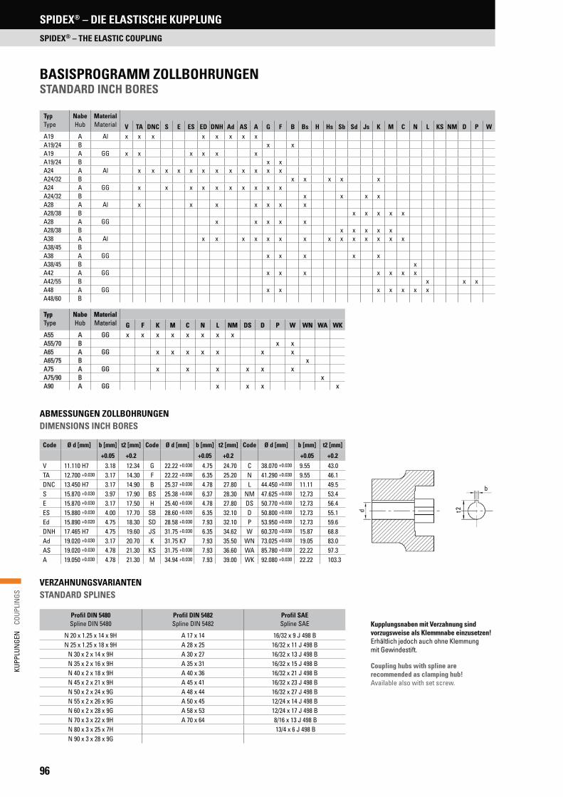
96
KUPP
LUN
GEN
C
OUPL
INGS
SPIDEX® – DIE ELASTISCHE KUPPLUNG
SPIDEX® – THE ELASTIC COUPLING
BASISPROGRAMM ZOLLBOHRUNGENSTANDARD INCH BORES
ABMESSUNGEN ZOLLBOHRUNGENDIMENSIONS INCH BORES
VERZAHNUNGSVARIANTENSTANDARD SPLINES
Kupplungsnaben mit Verzahnung sind vorzugsweise als Klemmnabe einzusetzen! Erhältlich jedoch auch ohne Klemmung mit Gewindestift.
Coupling hubs with spline are recommended as clamping hub! Available also with set screw.
TypType
NabeHub
MaterialMaterial V TA DNC S E ES ED DNH Ad AS A G F B Bs H Hs Sb Sd Js K M C N L KS NM D P W
A19 A Al x x x x x x x x A19/24 B x x A19 A GG x x x x x x A19/24 B x x A24 A Al x x x x x x x x x x x x A24/32 B x x x x x A24 A GG x x x x x x x x x x A24/32 B x x x x A28 A Al x x x x x x x A28/38 B x x x x x A28 A GG x x x x x A28/38 B x x x x x A38 A Al x x x x x x x x x x x x x x A38/45 B A38 A GG x x x x x A38/45 B x A42 A GG x x x x x x x A42/55 B x x x A48 A GG x x x x x x x A48/60 B
TypType
NabeHub
MaterialMaterial G F K M C N L NM DS D P W WN WA WK
A55 A GG x x x x x x x x A55/70 B x x A65 A GG x x x x x x x A65/75 B x A75 A GG x x x x x x A75/90 B x A90 A GG x x x x
Code Ø d [mm] b [mm] t2 [mm] Code Ø d [mm] b [mm] t2 [mm] Code Ø d [mm] b [mm] t2 [mm]
+0.05 +0.2 +0.05 +0.2 +0.05 +0.2V 11.110 H7 3.18 12.34 G 22.22 +0.030 4.75 24.70 C 38.070 +0.030 9.55 43.0TA 12.700 +0.030 3.17 14.30 F 22.22 +0.030 6.35 25.20 N 41.290 +0.030 9.55 46.1DNC 13.450 H7 3.17 14.90 B 25.37 +0.030 4.78 27.80 L 44.450 +0.030 11.11 49.5S 15.870 +0.030 3.97 17.90 BS 25.38 +0.030 6.37 28.30 NM 47.625 +0.030 12.73 53.4E 15.870 +0.030 3.17 17.50 H 25.40 +0.030 4.78 27.80 DS 50.770 +0.030 12.73 56.4ES 15.880 +0.030 4.00 17.70 SB 28.60 +0.020 6.35 32.10 D 50.800 +0.030 12.73 55.1Ed 15.890 +0.020 4.75 18.30 SD 28.58 +0.030 7.93 32.10 P 53.950 +0.030 12.73 59.6DNH 17.465 H7 4.75 19.60 JS 31.75 +0.030 6.35 34.62 W 60.370 +0.030 15.87 68.8Ad 19.020 +0.030 3.17 20.70 K 31.75 K7 7.93 35.50 WN 73.025 +0.030 19.05 83.0AS 19.020 +0.030 4.78 21.30 KS 31.75 +0.030 7.93 36.60 WA 85.780 +0.030 22.22 97.3A 19.050 +0.030 4.78 21.30 M 34.94 +0.030 7.93 39.00 WK 92.080 +0.030 22.22 103.3
Profil DIN 5480 Spline DIN 5480
Profil DIN 5482 Spline DIN 5482
Profil SAE Spline SAE
N 20 x 1.25 x 14 x 9H A 17 x 14 16/32 x 9 J 498 B N 25 x 1.25 x 18 x 9H A 28 x 25 16/32 x 11 J 498 B
N 30 x 2 x 14 x 9H A 30 x 27 16/32 x 13 J 498 BN 35 x 2 x 16 x 9H A 35 x 31 16/32 x 15 J 498 BN 40 x 2 x 18 x 9H A 40 x 36 16/32 x 21 J 498 BN 45 x 2 x 21 x 9H A 45 x 41 16/32 x 23 J 498 BN 50 x 2 x 24 x 9G A 48 x 44 16/32 x 27 J 498 BN 55 x 2 x 26 x 9G A 50 x 45 12/24 x 14 J 498 BN 60 x 2 x 28 x 9G A 58 x 53 12/24 x 17 J 498 B N 70 x 3 x 22 x 9H A 70 x 64 8/16 x 13 J 498 BN 80 x 3 x 25 x 7H 13/4 x 6 J 498 BN 90 x 3 x 28 x 9G
b
d t2

97
KUPP
LUN
GEN
C
OUPL
INGS
SPIDEX® – DIE ELASTISCHE KUPPLUNG
SPIDEX® – THE ELASTIC COUPLING
MAXIMAL ZULÄSSIGE VERLAGERUNGSWERTE FÜR ZAHNKRANZHÄRTEN 92°, 95°, 98° SHORE AMAX. PERMISSIBLE DISPLACEMENT VALUES FOR SPIDERS 92°, 95°, 98° SHORE A
Sorgfältiges Ausrichten der Wellen erhöht die Lebensdauer der Kupplung
ACHTUNG: MONTAGEANLEITUNG BEACHTENErhältlich unter www.rl-hydraulics.com
KEGELIGE BOHRUNGENTAPER BORES
d
b
t2
l
SPIDEX® Abmessungen Dimensions
[mm]
AxialversatzAxial
displacement
Radialversatz Radial displacement Kr [mm] Winkelversatz Angular displacement Kw [°]
Drehzahl Rotation n [1/min] Drehzahl Rotation n [1/min]
L E b s Ka [mm] 750 1000 1500 3000 750 1000 1500 3000A14 35 13 10 1.5
1.0 0.22 0.20 0.16 0.111.3 1.3 1.2 1.1A15 28 8 6 1.0
A19 66 16 12 2.0 1.2 0.27 0.24 0.20 0.13A24 78 18 14 2.0 1.4 0.30 0.27 0.22 0.15
1.11.0 0.9
0.8A28 90 20 15 2.5 1.5 0.34 0.30 0.25 0.17A38 114 24 18 3.0 1.8 0.38 0.35 0.28 0.19
1.1 1.0A42 126 26 20 3.0 2.0 0.43 0.38 0.32 0.21A48 140 28 21 3.5 2.1 0.50 0.44 0.36 0.25
1.21.2
1.10.9
A55 160 30 22 4.0 2.2 0.54 0.46 0.38 0.261.0A65 185 35 26 4.5 2.6 0.56 0.50 0.42 0.28
1.2A75 210 40 30 5.0 3.0 0.65 0.58 0.48 0.32
1.3A90 245 45 34 5.5 3.4 0.68 0.60 0.50 0.34
1.31.1A100 270 50 38 6.0 3.8 0.71 0.64 0.52 0.36
A110 295 55 42 6.5 4.2 0.75 0.67 0.55 0.381.3
A125 340 60 46 7.0 4.6 0.80 0.70 0.60 – –
Code Konus 1:8 Taper 1:8 Code Konus 1:5 Taper 1:5
Ø d b t2 I Ø d b t2 I…N/1 9.750 2.40 10.70 17.0 A10 9.85 2 10.85 11.5
…N/1c 11.600 3.00 12.90 16.5 As12 11.85 3 13.65 16.5…N/1e 13.000 2.40 13.80 21.0 B17 16.85 3 18.90 18.5…N/1d 14.000 3.00 15.50 17.5 C20 19.85 4 22.05 21.5…N/1b 14.300 3.20 15.65 19.5 Cs22 21.95 3 23.75 21.5…N/2 17.287 3.20 18.24 24.0 D25 24.85 5 27.90 26.5
…N/2a 17.287 4.00 18.94 24.0 E30 29.856
32.45 31.5…N/2b 17.287 3.00 18.24 24.0 F35 34.85 37.45 36.5…N/3 22.002 3.99 23.40 28.0 G40 39.85 42.45 41.5…N/4 25.463 4.78 28.86 36.0
…N/4b 25.463 5.00 28.23 36.0…N/4a 27.000 4.78 28.80 32.5…N/4g 28.450 6.00 29.33 38.5…N/5 33.176 6.38 35.39 44.0
…N/5a 33.176 7.00 35.39 44.0…N/6 43.057 7.95 46.46 51.0
…N/6a 41.150 8.00 44.25 42.0
• Das Längenmaß L vergrößert sich um die angegebenen Ka-Werte.• Die aufgeführten Verlagerungswerte sind allgemeine Richtwerte.• Bei gleichzeitigem Winkel- und Radialversatz können die angegebenen
Werte nur anteilmäßig ausgenutzt werden.• Die Tabellenwerte sind gültig für eine Betriebstemperatur T = +30 °C.
Bei einer Temperaturerhöhung müssen die max. zulässigen Radial- und Winkelverlagerungswerte mit dem Temperaturfaktor St multipliziert werden.
Temperatur T Temperature T -40 < +30 °C +30 < +40 °C +40 < +60 °C +60 < +80 °C +80 °C <
Faktor St Factor St 1.0 0.8 0.7 0.6 0.3
• The dimension L increases by the given Ka values.• The above mentioned displacement values are general guidelines.• In case of angular and radial displacements, the values can only be used
proportionately.• The values are valid for an operating temperature of T = +30 °C. If the
temperature increases, the permissible radial and simultaneous angular displacement values must be multiplied by the temperature factor St.
Careful alignment will extend the coupling life
CAUTION: CONSIDER THE ASSEMBLY INSTRUCTIONSAvailable at www.rl-hydraulics.com
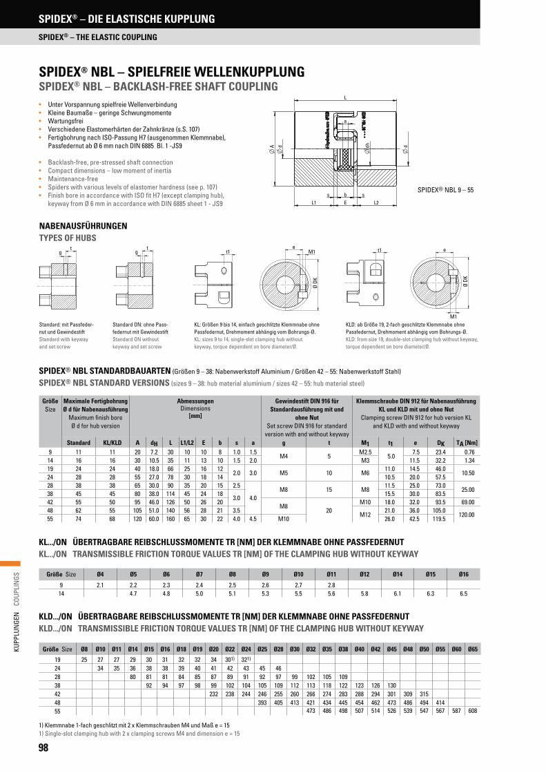
98
KUPP
LUN
GEN
C
OUPL
INGS
SPIDEX® – DIE ELASTISCHE KUPPLUNG
SPIDEX® – THE ELASTIC COUPLING
SPIDEX® NBL – SPIELFREIE WELLENKUPPLUNGSPIDEX® NBL – BACKLASH-FREE SHAFT COUPLING• Unter Vorspannung spielfreie Wellenverbindung • Kleine Baumaße – geringe Schwungmomente• Wartungsfrei• Verschiedene Elastomerhärten der Zahnkränze (s.S. 107)• Fertigbohrung nach ISO-Passung H7 (ausgenommen Klemmnabe),
Passfedernut ab Ø 6 mm nach DIN 6885 Bl. 1 -JS9
• Backlash-free, pre-stressed shaft connection• Compact dimensions – low moment of inertia• Maintenance-free• Spiders with various levels of elastomer hardness (see p. 107)• Finish bore in accordance with ISO fit H7 (except clamping hub),
keyway from Ø 6 mm in accordance with DIN 6885 sheet 1 - JS9
L
a
dhA
L2L1s b s
E
d d
SPIDEX® NBL 9 – 55
KL: Größen 9 bis 14, einfach geschlitzte Klemmnabe ohne Passfedernut, Drehmoment abhängig vom Bohrungs-Ø.KL: sizes 9 to 14, single-slot clamping hub without keyway, torque dependent on bore diameter/Ø.
KLD: ab Größe 19, 2-fach geschlitzte Klemmnabe ohne Passfedernut, Drehmoment abhängig vom Bohrungs-Ø.KLD: from size 19, double-slot clamping hub without keyway, torque dependent on bore diameter/Ø.
Standard ON: ohne Pass- federnut mit GewindestiftStandard ON without keyway and set screw
Standard: mit Passfeder- nut und GewindestiftStandard with keyway and set screw
NABENAUSFÜHRUNGENTYPES OF HUBS
KL.../ON ÜBERTRAGBARE REIBSCHLUSSMOMENTE TR [NM] DER KLEMMNABE OHNE PASSFEDERNUTKL.../ON TRANSMISSIBLE FRICTION TORQUE VALUES TR [NM] OF THE CLAMPING HUB WITHOUT KEYWAY
GrößeSize
Maximale Fertigbohrung Ø d für Nabenausführung
Maximum finish bore Ø d for hub version
Abmessungen Dimensions
[mm]
Gewindestift DIN 916 für Standardausführung mit und
ohne NutSet screw DIN 916 for standard
version with and without keyway
Klemmschraube DIN 912 für Nabenausführung KL und KLD mit und ohne Nut
Clamping screw DIN 912 for hub version KL and KLD with and without keyway
Standard KL/KLD A dH L L1/L2 E b s a g t M1 t1 e DK TA [Nm]9 11 11 20 7.2 30 10 10 8 1.0 1.5
M4 5M2.5
5.07.5 23.4 0.76
14 16 16 30 10.5 35 11 13 10 1.5 2.0 M3 11.5 32.2 1.3419 24 24 40 18.0 66 25 16 12
2.0 3.0 M5 10 M611.0 14.5 46.0
10.5024 28 28 55 27.0 78 30 18 14 10.5 20.0 57.528 38 38 65 30.0 90 35 20 15 2.5
4.0M8 15 M8
11.5 25.0 73.025.00
38 45 45 80 38.0 114 45 24 183.0
15.5 30.0 83.542 55 50 95 46.0 126 50 26 20
M820
M10 18.0 32.0 93.5 69.0048 62 55 105 51.0 140 56 28 21 3.5
M1221.0 36.0 105.0
120.0055 74 68 120 60.0 160 65 30 22 4.0 4.5 M10 26.0 42.5 119.5
SPIDEX® NBL STANDARDBAUARTEN (Größen 9 – 38: Nabenwerkstoff Aluminium / Größen 42 – 55: Nabenwerkstoff Stahl)
SPIDEX® NBL STANDARD VERSIONS (sizes 9 – 38: hub material aluminium / sizes 42 – 55: hub material steel)
Größe Size Ø4 Ø5 Ø6 Ø7 Ø8 Ø9 Ø10 Ø11 Ø12 Ø14 Ø15 Ø16
9 2.1 2.2 2.3 2.4 2.5 2.6 2.7 2.814 4.7 4.8 5.0 5.1 5.3 5.5 5.6 5.8 6.1 6.3 6.5
KLD.../ON ÜBERTRAGBARE REIBSCHLUSSMOMENTE TR [NM] DER KLEMMNABE OHNE PASSFEDERNUTKLD.../ON TRANSMISSIBLE FRICTION TORQUE VALUES TR [NM] OF THE CLAMPING HUB WITHOUT KEYWAY
Größe Size Ø8 Ø10 Ø11 Ø14 Ø15 Ø16 Ø18 Ø19 Ø20 Ø22 Ø24 Ø25 Ø28 Ø30 Ø32 Ø35 Ø38 Ø40 Ø42 Ø45 Ø48 Ø50 Ø55 Ø60 Ø65
19 25 27 27 29 30 31 32 32 34 301) 321)
24 34 35 36 38 38 39 40 41 42 43 45 4628 80 81 81 84 85 87 89 91 92 97 99 102 105 10938 92 94 97 98 99 102 104 105 109 112 113 118 122 123 126 13042 232 238 244 246 255 260 266 274 283 288 294 301 309 31548 393 405 413 421 434 445 454 462 473 486 494 41455 473 486 498 507 514 526 539 547 567 587 608
1) Klemmnabe 1-fach geschlitzt mit 2 x Klemmschrauben M4 und Maß e = 151) Single-slot clamping hub with 2 x clamping screws M4 and dimension e = 15

99
KUPP
LUN
GEN
C
OUPL
INGS
SPIDEX® – DIE ELASTISCHE KUPPLUNG
SPIDEX® – THE ELASTIC COUPLING
NBL-ZAHNKRÄNZENBL SPIDERS
GrößeSize
ZahnkranzSpider
DrehmomentTorque [Nm]
Max. DrehzahlMax. RPM n [1/min]
Statische DrehfedersteifeStatic torsional
stiffness
DynamischeDrehfedersteifeDynamic torsio-
nal stiffness
Radiale Steifheit
Radial stiffness
GewichtWeight
[kg]
Massenträgheits- moment
Moment of inertia J [kg m2]
NennContin.
TKN
MaximalMaximum
TKmax
StandardStandard
KL/KLD[Nm/rad]
bei 0.50 TKN
[Nm/rad]bei 0.50 TKN
[N/mm] NabeHub
(x 10-3)
ZahnkranzSpider (x 10-3)
NabeHub
(x 10-6)
ZahnkranzSpider (x 10-6)
NBL992° Shore A 3.0 6.0
19000 2380031.5 95 262
8 1.7 0.480 0.08598° Shore A 5.0 10.0 51.6 155 518
NBL1492° Shore A 7.5 15.0
12700 15900114.6 344 336
20 4.6 2.800 0.45798° Shore A 12.5 25.0 171.9 513 654
NBL1992° Shore A 10.0 20.0
9550 11900573.0 1720 1120
66 7.0 20.400 1.49098° Shore A 17.0 34.0 859.5 2580 2010
NBL2492° Shore A 35.0 70.0
6950 88501432.0 4296 1480
132 18.0 50.800 7.50098° Shore A 60.0 120.0 2063.0 6189 256064° Shore D 75.0 150.0 2978.0 8934 3696
NBL2892° Shore A 95.0 190.0
5850 73502292.0 6876 1780
253 29.0 200.300 16.50098° Shore A 160.0 320.0 3438.0 10314 320064° Shore D 200.0 400.0 4350.0 13050 4348
NBL3892° Shore A 190.0 380.0
4750 59504584.0 13752 2350
455 49.0 400.600 44.60098° Shore A 325.0 650.0 7160.0 21486 440064° Shore D 405.0 810.0 10540.0 31620 6474
NBL4292° Shore A 265.0 530.0
4000 50006300.0 14490 2430
1850 79.0 2246.000 100.00098° Shore A 450.0 900.0 19200.0 48000 557064° Shore D 560.0 1120.0 27580.0 68950 7270
NBL4892° Shore A 310.0 620.0
3600 45507850.0 18055 2580
2520 98.0 3786.000 200.00098° Shore A 525.0 1050.0 22370.0 55925 593064° Shore D 655.0 1310.0 36200.0 90500 8274
NBL5592° Shore A 410.0 820.0
3150 39509500.0 21850 2980
3800 115.0 7496.000 300.00098° Shore A 685.0 1370.0 23800.0 59500 668664° Shore D 825.0 1650.0 41460.0 103650 9248
Zahnkranz Polyurethan 92° Shore A NBLSpider polyurethane 92° Shore A NBL
• Gelb Yellow
• Dauertemperatur -40 bis +90 °C Continuous temperature -40 to +90 °C
• Max. Temperatur kurzzeitig -50 bis +120 °C Max. short-term temperature -50 to +120 °C
• Für Antriebe von elektrischen Mess- und Regelsystemen For drives of electrical measurement & control systems
Zahnkranz Polyurethan 98° Shore A NBLSpider polyurethane 98° Shore A NBL
• Rot Red
• Dauertemperatur -30 bis +90 °C Continuous temperature -30 to +90 °C
• Max. Temperatur kurzzeitig -40 bis +120 °C Max. short-term temperature -40 to +120 °C
• Positionierantriebe Positioning motors
• Hauptspindelantriebe bei hoher Beanspruchung Main spindle drives with high loads
Zahnkranz Polyurethan 64° Shore D NBLSpider polyurethane 64° Shore D NBL
• Grün Green
• Dauertemperatur -20 bis +110 °C Continuous temperature -20 to +110 °C
• Max. Temperatur kurzzeitig -30 bis +120 °C Max. short-term temperature -30 to +120 °C
• Hohe Belastbarkeit mit geringem Verdrehwinkel High loading with low torsion angle
TECHNISCHE DATENTECHNICAL DATA

100
KUPP
LUN
GEN
C
OUPL
INGS
TYPENBEZEICHNUNG FÜR SPIDEX® NBLMODEL TYPE FOR SPIDEX® NBL
ERLÄUTERUNG ZUM BESTELLSCHLÜSSEL EXPLANATION OF ORDER CODE
SPIDEX® KLD Al NBL 38 25H7 ON L = 20 SO
Sonderausführungen Special designs
Nabenlänge Length of hub
Nabenbohrung, Zusatz Hub bore, supplement
Nabenbohrung, Grundform Hub bore, basic form
Baugröße Size
Typ Type
Nabenwerkstoff Material of hub
Nabenausführung Design of hub
NABENAUSFÜHRUNGEN DESIGN OF HUBS
Ausführung Design
BestellschlüsselOrder code
BeschreibungDescription
BeispielExample
StandardStandard
- • zylindrische Bohrung mit Passfedernut nach DIN 6885/1
• cylindrical bore with keyway in accordance with DIN 6885/1
-…- ON • zylindrische Bohrung ohne Passfedernut
• cylindrical bore without keyway
Klemmnabe, einfach geschlitztClamping hub, single slot
KL • zylindrische Bohrung mit Passfedernut nach DIN 6885/1• Nabe einfach geschlitzt mit seitlicher Klemmschraube
• cylindrical bore with keyway in accordance with DIN 6885/1• single-slot hub with lateral clamping screw
KL-…-ON • zylindrische Bohrung ohne Passfedernut• Nabe einfach geschlitzt mit seitlicher Klemmschraube
• cylindrical bore without keyway• single-slot hub with lateral clamping screw
Klemmnabe, doppelt geschlitztClamping hub, double slot
KLD • zylindrische Bohrung mit Passfedernut nach DIN 6885/1• Nabe doppelt geschlitzt mit seitlicher Klemmschraube
• cylindrical bore with keyway in accordance with DIN 6885/1• double-slot hub with lateral clamping screw
KLD-…-ON • zylindrische Bohrung ohne Passfedernut• Nabe doppelt geschlitzt mit seitlicher Klemmschraube
• cylindrical bore without keyway• double-slot hub with lateral clamping screw
SPIDEX® – DIE ELASTISCHE KUPPLUNG
SPIDEX® – THE ELASTIC COUPLING

101
KUPP
LUN
GEN
C
OUPL
INGS
DENTEX®/DENTEX® FL – DIE FLEXIBLE KUPPLUNG
DENTEX®/DENTEX® FL – THE FLEXIBLE COUPLING
FUNKTIONSWEISETECHNICAL DESCRIPTION
The DENTEX® coupling is a flexible gear coupling whose typical features are two congruent hubs with crowned teeth which transmit torque by meshing with the internal toothing of a housing component. The coupling sleeve with axially parallel involute gearing is centered at the tooth flanks of the coupling hub. The coupling design fulfils the requirement for compensation of radial, angular and axial shaft displacements in order to relieve the neighbouring shaft bearings from non-controlled, additional loads. Even with the maximum permissible dis-placement, edge contact of the teeth is excluded and there will be no periodic variation of the angular velocity. The high internal cushioning properties of the plastic material used for the coupling sleeve reduce the effect of shock loading.
DENTEX® couplings are suitable both for horizontal and vertical shaft con-nections, for reversing and intermittent service. The steel/plastic combina-tion also has the advantage that no lubrication by oil or grease is required; the coupling, therefore, does not need any maintenance. The 6.6-polyamide used for the coupling sleeve is distinguished by its excellent sliding properties and wear resistance; it is also resistant to all market-standard lubricants and hydraulic fluids. Maximum service reliability is guaranteed at temperatures between -25 °C and +80 °C. A coupling sleeve in heat-stabilised polyamide is required for temperatures up to +140 °C.
• Ausgleich axialer, radialer und winkliger Wellenverlagerungen durch doppelkardanische Wirkungsweise
• Einfache, zeitsparende Montage• Sehr gutes elektrisches Isoliervermögen• Hohe thermische Beständigkeit• Wartungsfrei• Atex-Klassifizierung: siehe Seite 173
• Compensation of axial, radial and angular misalignment of shafts through double cardanic action
• Quick and easy assembly• Excellent electrical insulating properties• High thermal stability• No maintenance• Atex classification: see page 173
DENTEX®/DENTEX® FL – DIE FLEXIBLE KUPPLUNGDENTEX®/DENTEX® FL – THE FLEXIBLE COUPLING
Die DENTEX®-Kupplung ist eine flexible Wellenverbindung, um axiale, radi-ale und winklige Wellenverlagerungen auszugleichen. Das Drehmoment wird durch Ineinandergreifen von zwei kongruenten Naben mit ballig profilierten Zähnen in einer innenverzahnten Kunststoffhülse formschlüssig übertragen. Das Kupplungsprinzip bewirkt, dass die unmittelbar benachbarten Wellenla-ger vor unkontrolliert auftretenden Lagerkräften geschützt werden. Die Rück-stellkräfte bei Winkel- und Radialverlagerung können aufgrund der doppel-kardanischen Wirkungsweise vernachlässigt werden, es treten auch keine periodischen Schwankungen der Winkelgeschwindigkeit auf.
DENTEX®-Kupplungen sind für horizontale oder vertikale Wellenverbin-dungen geeignet und ermöglichen eine einfache und zeitsparende Monta-ge. Durch die Kombination der Werkstoffe Stahl/Kunststoff entfällt die sonst übliche Öl- oder Fettschmierung; die Kupplung gilt als absolut wartungsfrei. Durch die Verwendung von 6.6-Polyamid für die Kunststoffhülse wurden bes-te Gleit- und Verschleißeigenschaften erzielt, außerdem ist das Material re-sistent gegen alle handelsüblichen Schmieröle und Hydraulikflüssigkeiten. Eine optimale Betriebssicherheit liegt innerhalb der Temperaturbereiche -25 °C bis +80 °C. Für Betriebstemperaturen bis +140 °C ist der Einsatz einer Kupplungshülse aus hitzestabilisiertem Polyamid erforderlich.
TYPENBEZEICHNUNG MODEL TYPE
StandardStandard –
KlemmnabeClamping hub KL
NabenausführungType of hub
Serie BSeries B
14242832384248556580
100Serie B3RSeries B3R
2428
Serie B3R/B4RSeries B3R/B4R
32456580
100
KL B 42 . 38 H 7 L = 60 SO
Beispiel FertigbohrungExample finish bore
Ung. Ungebohrt UnboredVorg. Vorgebohrt Prebored38H7 Metrisch* Metric*B17 Kegelig* Tapered*F Zöllig* Inch bored*
ProfileSplines
SAE SAE 16/32Z13**DIN 5482 A35x31**DIN 5480 N30x2x14x9G**
Verlängerte NabenExtended hub length
– StandardStandard
60 Siehe Seite 103See page 103
SonderbearbeitungSpecial machining
– StandardStandard
SO SonderzeichnungSpecial drawing
* Siehe Seite 105** Siehe Seite 96* See page 105** See page 96
PRODUKTEIGENSCHAFTENFEATURES
NG
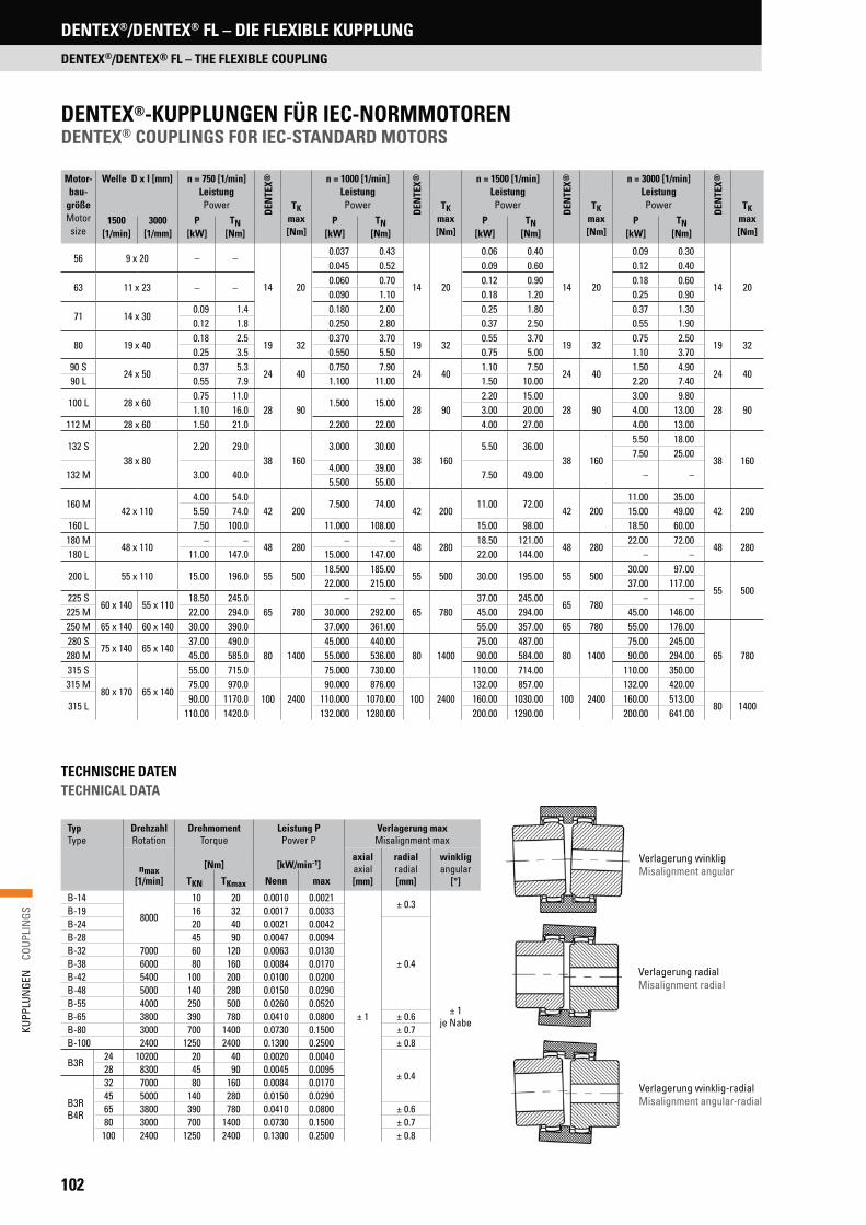
102
KUPP
LUN
GEN
C
OUPL
INGS
DENTEX®/DENTEX® FL – DIE FLEXIBLE KUPPLUNG
DENTEX®/DENTEX® FL – THE FLEXIBLE COUPLING
DENTEX®-KUPPLUNGEN FÜR IEC-NORMMOTOREN DENTEX® COUPLINGS FOR IEC-STANDARD MOTORS
TECHNISCHE DATEN TECHNICAL DATA
Verlagerung winkligMisalignment angular
Verlagerung radialMisalignment radial
Verlagerung winklig-radialMisalignment angular-radial
TypType
DrehzahlRotation
Drehmoment Torque
[Nm]
Leistung PPower P
[kW/min-1]
Verlagerung maxMisalignment max
nmax[1/min]
axialaxial[mm]
radialradial[mm]
winkligangular
[°]TKN TKmax Nenn max
B-14
8000
10 20 0.0010 0.0021
± 1
± 0.3
± 1je Nabe
B-19 16 32 0.0017 0.0033B-24 20 40 0.0021 0.0042
± 0.4
B-28 45 90 0.0047 0.0094B-32 7000 60 120 0.0063 0.0130B-38 6000 80 160 0.0084 0.0170B-42 5400 100 200 0.0100 0.0200B-48 5000 140 280 0.0150 0.0290B-55 4000 250 500 0.0260 0.0520B-65 3800 390 780 0.0410 0.0800 ± 0.6B-80 3000 700 1400 0.0730 0.1500 ± 0.7B-100 2400 1250 2400 0.1300 0.2500 ± 0.8
B3R24 10200 20 40 0.0020 0.0040
± 0.428 8300 45 90 0.0045 0.0095
B3RB4R
32 7000 80 160 0.0084 0.017045 5000 140 280 0.0150 0.029065 3800 390 780 0.0410 0.0800 ± 0.680 3000 700 1400 0.0730 0.1500 ± 0.7
100 2400 1250 2400 0.1300 0.2500 ± 0.8
Motor-bau-
größeMotor
size
Welle D x I [mm] n = 750 [1/min]LeistungPower
DEN
TEX® n = 1000 [1/min]
LeistungPower
DEN
TEX® n = 1500 [1/min]
LeistungPower
DEN
TEX® n = 3000 [1/min]
LeistungPower
DEN
TEX®
TKmax[Nm]
TKmax[Nm]
TKmax[Nm]
TKmax[Nm]
1500[1/min]
3000[1/mm]
P [kW]
TN[Nm]
P [kW]
TN[Nm]
P [kW]
TN[Nm]
P [kW]
TN[Nm]
56 9 x 20 – –
14 20
0.037 0.43
14 20
0.06 0.40
14 20
0.09 0.30
14 20
0.045 0.52 0.09 0.60 0.12 0.40
63 11 x 23 – –0.060 0.70 0.12 0.90 0.18 0.600.090 1.10 0.18 1.20 0.25 0.90
71 14 x 300.09 1.4 0.180 2.00 0.25 1.80 0.37 1.300.12 1.8 0.250 2.80 0.37 2.50 0.55 1.90
80 19 x 400.18 2.5
19 320.370 3.70
19 320.55 3.70
19 320.75 2.50
19 320.25 3.5 0.550 5.50 0.75 5.00 1.10 3.70
90 S24 x 50
0.37 5.3 24 40
0.750 7.9024 40
1.10 7.5024 40
1.50 4.9024 40
90 L 0.55 7.9 1.100 11.00 1.50 10.00 2.20 7.40
100 L 28 x 600.75 11.0
28 901.500 15.00
28 902.20 15.00
28 903.00 9.80
28 901.10 16.0 3.00 20.00 4.00 13.00112 M 28 x 60 1.50 21.0 2.200 22.00 4.00 27.00 4.00 13.00
132 S38 x 80
2.20 29.038 160
3.000 30.0038 160
5.50 36.0038 160
5.50 18.00
38 1607.50 25.00
132 M 3.00 40.04.000 39.00
7.50 49.00 – –5.500 55.00
160 M42 x 110
4.00 54.042 200
7.500 74.0042 200
11.00 72.0042 200
11.00 35.0042 2005.50 74.0 15.00 49.00
160 L 7.50 100.0 11.000 108.00 15.00 98.00 18.50 60.00180 M
48 x 110– –
48 280– –
48 28018.50 121.00
48 28022.00 72.00
48 280180 L 11.00 147.0 15.000 147.00 22.00 144.00 – –
200 L 55 x 110 15.00 196.0 55 50018.500 185.00
55 500 30.00 195.00 55 50030.00 97.00
55 50022.000 215.00 37.00 117.00
225 S60 x 140 55 x 110
18.50 245.065 780
– –65 780
37.00 245.0065 780
– –225 M 22.00 294.0 30.000 292.00 45.00 294.00 45.00 146.00250 M 65 x 140 60 x 140 30.00 390.0 37.000 361.00 55.00 357.00 65 780 55.00 176.00
65 780280 S
75 x 140 65 x 14037.00 490.0
80 140045.000 440.00
80 140075.00 487.00
80 140075.00 245.00
280 M 45.00 585.0 55.000 536.00 90.00 584.00 90.00 294.00315 S
80 x 170 65 x 140
55.00 715.0 75.000 730.00 110.00 714.00 110.00 350.00315 M 75.00 970.0
100 240090.000 876.00
100 2400132.00 857.00
100 2400132.00 420.00
315 L90.00 1170.0 110.000 1070.00 160.00 1030.00 160.00 513.00
80 1400110.00 1420.0 132.000 1280.00 200.00 1290.00 200.00 641.00

103
KUPP
LUN
GEN
C
OUPL
INGS
DENTEX®/DENTEX® FL – DIE FLEXIBLE KUPPLUNG
DENTEX®/DENTEX® FL – THE FLEXIBLE COUPLING
TypType
VorbohrungPrebored
FertigbohrungFinish bore
d [mm]
Abmessungen Dimensions
[mm]
SonderlängeExtended hub
length
GewichtWeight
Massenträg-heitsmomentMoment of
inertia
min max A B L L1/L2 E H* C F g f L1/L2 [kg] J [kg m2]
B-14 5 6 14 40 25 50 23
4
15 6.5 37
M5 6
40 0.175 0.000030
B-19 8 9 19 48 30 54 2517
7.0 37 – 0.320 0.000470
B-249 10
24 52 36 56 26 7.5 41 50 0.316 0.000093
B-28 28 66 44
84 40 20
19.0 46
M8 10
550.739 0.000310
B-32 11 12 32 76 5018.0 48
0.950 0.000550
B-38 12 14 38 83 58
60
1.220 0.000870
B-4216 20
42 92 65 88 42 22 19.0 50 1.490 0.001400
B-48 48 100 68 104 50 22 27.0 50 1.810 0.001800
B-55 – 25 55 125 83 124 60 30 30.0 65
M10 20
– 3.450 0.004600
B-65 0/30 10/32 65 140 96 144 70 32 36.0 72 – 5.180 0.009900
B-80 – 30 80 175 124 186 90 6 45 46.5 93 – 11.500 0.037000
B-100 35 40 100 210 152 228 110 8 55 63.0 102 M12 30 – 20.500 0.115600
DENTEX®-KUPPLUNGEN, SERIE BDENTEX® COUPLINGS, SERIES B
MONTAGEHINWEISASSEMBLY INSTRUCTION
H* ist das Mindestmaß, um welches die Aggregate auseinander geschoben werden müssen, um einen radialen Ausbau zu ermöglichen. Fertigbohrung nach ISO-Passung H7, Passfedernut nach DIN 6885, Blatt 1 (JS9). Gewicht und Massenträgheitsmoment beziehen sich auf den maximal möglichen Durchmesser d ohne Nut.
Bei Montage der Kupplung ist zu beachten, dass die Naben mit den Wellenenden bündig sind und das E-Maß eingehalten wird. Das E-Maß lässt sich anhand der Gesamtbaulänge L kontrollieren. Ein nicht exakt eingehaltenes E-Maß hat negativen Einfluss auf die Funktion der Kupplung. Vor Inbetriebnahme der Kupplung ist zu prüfen, ob die Verbindungshülse leicht axial verschiebbar ist. Die zulässigen Verlagerungswerte sind abhängig von Drehzahl und Leistung.
During assembly it is important that the hubs are correctly fitted on the shafts and that the dimension E is maintained. The dimension E can be checked by the total assembly length L. An inexact dimension E has a negative influence on the performance of the coupling. Check that axial movement of the coupling sleeve can be effected easily before operating the coupling for the first time. The permissible displacement values are dependent on rotation and transmitted power.
TECHNISCHE DATEN TECHNICAL DATA
H* is the minimum dimension required for the disassembly of the aggregates in a radial direction. Finish bore acc. to ISO standard H7, keyway acc. to DIN 6885, sheet 1 (JS9). Weight and moment of inertia values refer to maximum diameter d without keyway.

104
KUPP
LUN
GEN
C
OUPL
INGS
DENTEX®/DENTEX® FL – DIE FLEXIBLE KUPPLUNG
DENTEX®/DENTEX® FL – THE FLEXIBLE COUPLING
TypType
FertigbohrungFinish bore
d [mm]
Abmessungen Dimensions
[mm]
GewichtWeight
Massenträgheits-moment
Moment of inertia
min max A B L L1/L2 E H* C F g f [kg] J [kg m2]B4R 32 12 32 84 50 84 40
418.0
13.0 58M8 10
1.1 0.0007B4R 45 20 42 100 65 88 42 14.0 60 1.5 0.0017B4R 65 25 65 140 96 144 70 15.0 30.0 84
M10 205.4 0.0118
B4R 80 30 80 175 124 186 90 6 3.5 46.5 93 11.7 0.0385B4R 100 40 100 210 152 228 110 8 – 63.0 102 M12 30 20.8 0.0987
Typ B3RType B3R
Typ B4RType B4R
MIT AUSSENLIEGENDEN ANLAUF- UND SEEGERRINGENWITH OUTER BEARING RINGS AND SEEGER CIRCLIPS
TypType
FertigbohrungFinish bore
d [mm]
Abmessungen Dimensions
[mm]
GewichtWeight
Massenträgheits-moment
Moment of inertia
min max A B L L1/L2 E H* C F g f [kg] J [kg m2]B3R 24
1024 58 36 56 26
4
23.5 2.5 51 M5 6 0.3 0.0001B3R 28 28 70 44 84 40 26.0 14.0 56
M810
0.8 0.0004B3R 32 12 32 84 50 84 40 27.0 13.0 58 1.1 0.0007B3R 45 20 42 100 65 88 42 28.0 14.0 60 M8 1.5 0.0016B3R 65 25 65 140 96 144 70 40.0 30.0 84
M10 205.4 0.0115
B3R 80 30 80 175 124 186 90 6 45.0 46.5 93 11.6 0.0378B3R 100 40 100 210 152 228 110 8 49.0 63.0 102 M12 30 20.7 0.0974
MIT INNEN- UND AUSSEN-SEEGERRINGENWITH INNER AND OUTER SEEGER CIRCLIPS
H* ist das Mindestmaß, um welches die Aggregate auseinander geschoben werden müssen, um einen radialen Ausbau zu ermöglichen. Fertigbohrung nach ISO-Passung H7, Passfedernut nach DIN 6885, Blatt 1 (JS9). Gewicht und Massenträgheitsmoment beziehen sich auf den maximal möglichen Durchmesser d ohne Nut.
TECHNISCHE DATEN TECHNICAL DATA
TECHNISCHE DATEN TECHNICAL DATA
H* is the minimum dimension required for the disassembly of the aggregates in a radial direction. Finish bore acc. to ISO standard H7, keyway acc. to DIN 6885, sheet 1 (JS9). Weight and moment of inertia values refer to maximum diameter d without keyway.
DENTEX®-KUPPLUNGEN, SERIE B3RDENTEX® COUPLINGS, SERIES B3R
DENTEX®-KUPPLUNGEN, SERIE B4RDENTEX® COUPLINGS, SERIES B4R
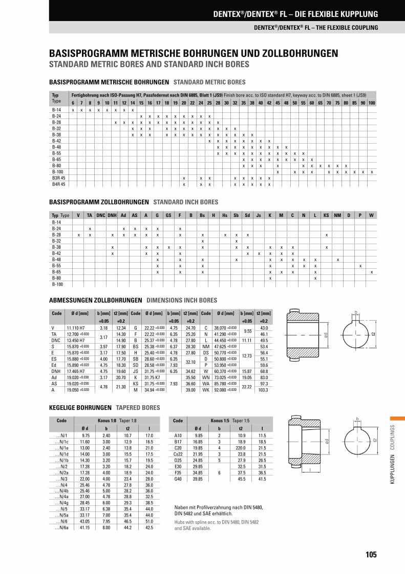
105
KUPP
LUN
GEN
C
OUPL
INGS
DENTEX®/DENTEX® FL – DIE FLEXIBLE KUPPLUNG
DENTEX®/DENTEX® FL – THE FLEXIBLE COUPLING
TypType
Fertigbohrung nach ISO-Passung H7, Passfedernut nach DIN 6885, Blatt 1 (JS9) Finish bore acc. to ISO standard H7, keyway acc. to DIN 6885, sheet 1 (JS9)
6 7 8 9 10 11 12 14 15 16 17 18 19 20 22 24 25 28 30 32 35 38 40 42 45 48 50 55 60 65 70 75 80 85 90 100B-14 x x x x x x x xB-24 x x x x x x x x xB-28 x x x x x x x x x x x x xB-32 x x x x x x x x x x x xB-38 x x x x x x x x x x x x x xB-42 x x x x x x x xB-48 x x x x x x x x xB-55 x x x x x x x x x x xB-65 x x x x x x x x xB-80 x x x x x x x x x xB-100 x x x x x x x x x xB3R 45 x x x x x x x xB4R 45 x x x x x x x x
BASISPROGRAMM METRISCHE BOHRUNGEN STANDARD METRIC BORES
ABMESSUNGEN ZOLLBOHRUNGEN DIMENSIONS INCH BORES
BASISPROGRAMM ZOLLBOHRUNGEN STANDARD INCH BORES
KEGELIGE BOHRUNGEN TAPERED BORES
Typ Type V TA DNC DNH Ad AS A G GS F B Bs H Hs Sb Sd Js K M C N L KS NM D P WB-14B-24 x x x x x xB-28 x x x x x x x x x x x x xB-32 x xB-38 x x x x x x x x x x x xB-42 x x x x x x x x xB-48 x x x x x x x x x xB-55 x x x x x x x xB-65 x x x x x x x xB-80 x xB-100
Naben mit Profilverzahnung nach DIN 5480, DIN 5482 und SAE erhältlich.
Hubs with spline acc. to DIN 5480, DIN 5482 and SAE available.
Code Ø d [mm] b [mm] t2 [mm] Code Ø d [mm] b [mm] t2 [mm] Code Ø d [mm] b [mm] t2 [mm]
+0.05 +0.2 +0.05 +0.2 +0.05 +0.2V 11.110 H7 3.18 12.34 G 22.22 +0.030 4.75 24.70 C 38.070 +0.030
9.5543.0
TA 12.700 +0.0303.17
14.30 F 22.22 +0.030 6.35 25.20 N 41.290 +0.030 46.1DNC 13.450 H7 14.90 B 25.37 +0.030 4.78 27.80 L 44.450 +0.030 11.11 49.5S 15.870 +0.030 3.97 17.90 BS 25.38 +0.030 6.37 28.30 NM 47.625 +0.030
12.73
53.4E 15.870 +0.030 3.17 17.50 H 25.40 +0.030 4.78 27.80 DS 50.770 +0.030 56.4ES 15.880 +0.030 4.00 17.70 SB 28.60 +0.020 6.35
32.10D 50.800 +0.030 55.1
Ed 15.890 +0.020 4.75 18.30 SD 28.58 +0.030 7.93 P 53.950 +0.030 59.6DNH 17.465 H7 4.75 19.60 JS 31.75 +0.030 6.35 34.62 W 60.370 +0.030 15.87 68.8Ad 19.020 +0.030 3.17 20.70 K 31.75 K7
7.9335.50 WN 73.025 +0.030 19.05 83.0
AS 19.020 +0.0304.78 21.30
KS 31.75 +0.030 36.60 WA 85.780 +0.03022.22
97.3A 19.050 +0.030 M 34.94 +0.030 39.00 WK 92.080 +0.030 103.3
Code Konus 1:8 Taper 1:8 Code Konus 1:5 Taper 1:5
Ø d b t2 I Ø d b t2 I…N/1 9.75 2.40 10.7 17.0 A10 9.85 2 10.9 11.5
…N/1c 11.60 3.00 12.9 16.5 B17 16.85 3 18.9 18.5…N/1e 13.00 2.40 13.8 21.0 C20 19.85 4 220.0 21.5…N/1d 14.00 3.00 15.5 17.5 Cs22 21.95 3 23.8 21.5…N/1b 14.30 3.20 15.7 19.5 D25 24.85 5 27.9 26.5…N/2 17.28 3.20 18.2 24.0 E30 29.85
632.5 31.5
…N/2a 17.28 4.00 18.9 24.0 F35 34.85 37.5 36.5…N/3 22.00 4.00 23.4 28.0 G40 39.85 45.5 41.5…N/4 25.46 4.78 27.8 36.0
…N/4b 25.46 5.00 28.2 36.0…N/4a 27.00 4.78 28.8 32.5…N/4g 28.45 6.00 29.3 38.5…N/5 33.17 6.38 35.4 44.0
…N/5a 33.17 7.00 35.4 44.0…N/6 43.05 7.95 46.5 51.0
…N/6a 41.15 8.00 44.2 42.5
BASISPROGRAMM METRISCHE BOHRUNGEN UND ZOLLBOHRUNGENSTANDARD METRIC BORES AND STANDARD INCH BORES

106
KUPP
LUN
GEN
C
OUPL
INGS
DENTEX®/DENTEX® FL – DIE FLEXIBLE KUPPLUNG
DENTEX®/DENTEX® FL – THE FLEXIBLE COUPLING
Typisches Einbaubeispiel für eine DENTEX® FL-Kupplung zwischen Dieselmotor und Hydraulikpumpe
Typical example for an installation of a DENTEX® FL coupling between diesel motor and hydraulic pump
*Hochbelastbare Naben auf Anfrage*Hubs resistant against high loads are available on request
DREHSTARRE FLANSCHKUPPLUNGEN FÜR DIESELMOTORISCHE ANTRIEBETORSIONALLY RIGID FLANGE COUPLINGS FOR DIESEL DRIVEN UNITS
Die glasfaserverstärkten Polyamid-Flansche der DENTEX® FL-Kupplungen basieren auf den genannten SAE-Anschlussmaßen für alle gängigen Dieselmotoren. Die DENTEX® FL-Kupplung ermöglicht eine formschlüssige Verbindung zwischen Dieselmotor und Hydraulikpumpe. Die Pumpenzentrierung erfolgt über das SAE-Gehäuse. Falls bei Pumpenwellen mit Profilverzahnung (DIN 5480, 5482, SAE) eine Nabensicherung durch Endscheibe und Schraube nicht möglich ist, sollte die Verwendung einer Klemmnabenverbindung vorgesehen werden. Die radiale Verspannung gewährleistet einen spielfreien Sitz auf der Pumpenwelle.
The glass-fibre reinforced polyamide coupling flanges of the DENTEX® FL couplings are based on the above mentioned mounting clearances for all conventional diesel motors. The DENTEX® FL coupling allows an interlocking connection between diesel motor and hydraulic pump. The pump is centred via the SAE housing. Should the securing of the hub by means of end-disc and screw not be possible in the case of pump shafts with profiled gear teeth (acc. to Standardization DIN 5480, 5482, SAE), the use of a clamping hub connection should be considered. The radial distortion guarantees a backlash-free fit on the pump shaft.
Bestellbeispiel: Bauart und Kupplungsgröße DENTEX® 48 FL, SAE-Flanschgröße 10, Fertigungsbohrung und Nabenlänge Ø 40 x 50
Ordering example: Type and coupling size DENTEX® 48 FL, SAE flange size 10, manufacturing bore and hub length Ø 40 x 50
• Minimale Einbaulänge• Blindmontage durch axiales Zusammenstecken• Wartungsfrei durch Werkstoffpaarung Kunststoff/Stahl• Glasfaserverstärkter Polyamidflansch hitzebeständig
bis +120 °C• Hohes Axialspiel von ± 2 mm schützt die benachbarten
Wellenlager vor auftretenden Lagerkräften• Sonderflansche lieferbar• Hohe Drehsteifigkeit – resonanzfreier Betrieb• Atex-Klassifizierung: siehe Seite 173
Größe*Size*
DrehmomentTorque[Nm]
Nabe bei max. Bohr-ØHub at max. bore Ø
Flansche nach SAEFlanges SAE
DrehfedersteifeDynamic torsional stiffness
MassenträgheitsmomentMoment of inertia
J [kg m2]
GewichtWeight
[kg]TKN TKmax TKW 6 1/2‘‘ 7 1/2‘‘ 8‘‘ 10‘‘ 11 1/2‘‘ 14‘‘ [Nm/rad]
42
240 480 120
0.0006 0.6750.4000 0.5200 0.5000 0.7500
0.30 TKN = 35 x 103
0.50 TKN = 75 x 103
0.0025 0.0045 0.0048 0.01000.75 TKN = 105 x 103
1.00 TKN = 125 x 103
48 0.0007 0.7900.3200 0.4300 0.5100 0.6400
0.30 TKN = 35 x 103
0.50 TKN = 75 x 103
0.0021 0.0035 0.0049 0.00850.75 TKN = 105 x 103
1.00 TKN = 125 x 103
65 650 1600 325 0.0039 2.1900.6400 0.8900
0.30 TKN = 110 x 103
0.50 TKN = 160 x 103
0.0065 0.01200.75 TKN = 200 x 103
1.00 TKN = 230 x 103
80 1200 3000 600 0.0151 5.200
1.12000.30 TKN = 200 x 103
0.50 TKN = 410 x 103
0.02200.75 TKN = 580 x 103
1.00 TKN = 700 x 103
0.73500.30 TKN = 200 x 103
0.50 TKN = 410 x 103
0.18700.75 TKN = 580 x 103
1.00 TKN = 700 x 103
TECHNISCHE DATEN TECHNICAL DATA
• Minimum mounting length• Blind mounting through push-fit assembly• Maintenance-free due to steel/plastic combination• Glass-fibre reinforced polyamide coupling flanges
heat resistant up to +120 °C• High axial play of ± 2 mm protecting neighbouring
shaft bearings from additional loads• Special flanges available• High torsional stiffness – resonance-free operation• Atex classification: see page 173
DENTEX® FL-KUPPLUNGENDENTEX® FL COUPLINGS

107
KUPP
LUN
GEN
C
OUPL
INGS
DENTEX®/DENTEX® FL – DIE FLEXIBLE KUPPLUNG
DENTEX®/DENTEX® FL – THE FLEXIBLE COUPLING
NenngrößeNominal dimension
Lochkreis-ØCircular bore Ø
Außen-ØOuter Ø
Befestigungsbohrung ØClamping borehole Ø
AnzahlNumber
D1 [mm] D [mm] [mm] z6 1/2‘‘ 200.02 215.90 9 67 1/2‘‘ 222.25 241.30 88 ‘‘ 244.47 263.52
116
10 ‘‘ 295.27 314.32811 1/2‘‘ 333.37 352.42
14‘‘* 438.15 466.72 14
NenngrößeNominal dimension
Lochkreis-ØCircular bore Ø
Außen-ØOuter Ø
Befestigungsbohrung ØClamping borehole Ø
Zentrier-ØCentre Ø
D1 [mm] D [mm] [mm] [mm]96 50 96 4.0 x 8.0 70125 100 125 3.0 x 8.0 80135 135 3.0 x 10.5 135150 130 150 5.0 x 8.0 106152 122 152 3.0 x 12.0 105155 125 155 155210 185 210 3.0 x 10.0 125
220165
2206.0 x 10.0 220
185 3.0 x 12.0 125
DENTEX® FL-KUPPLUNGENDENTEX® FL COUPLINGS
*2-teilig *2-parts
Größen 165, 180 und 252 auf Anfrage Dimensions 165, 180 and 252 on request
FLANSCH- UND NABENABMESSUNGEN SAE FLANGE AND HUB DIMENSIONS SAE
AUSWAHLTABELLE DENTEX® FL-FLANSCHKUPPLUNG MENU TABLE DENTEX® FL FLANGE COUPLING
* Anschlagseite Montage kurz* Stop side mounting short
L4L5
L4L5
d d
D 2D
L2L3
L1
B D
L3
L1B 2
D
**
D1 (z
= A
nzah
l/Num
ber)
D1 (z
= A
nzah
l/Num
ber)
GrößeSize
FertigbohrungFinish bore
AbmessungenDimensions
[mm]
SonderlängeSpecial length
[mm]
Nennmaß nach SAENominal dimension acc. to standardisation SAE
[D]
min max B D2 L1 L2 L3 L4 L5 L1 max 6 1/2 ‘‘ 7 1/2 ‘‘ 8 ‘‘ 10 ‘‘ 11 1/2 ‘‘ 14 ‘‘42
2042 65
10042 33 42
20 13 60x x x x
48 48 68 50 41 50 x x x x
65 25 65 96132
70 60 7027 21
–x
17231 22 x
80 30 80 124 90 78 87 30 21 x x
Nenngröße Nominal dimension
DENTEX® Naben-TypDENTEX® hub type
Motorhersteller/Typ (Beispiele)Engine manufacturer (examples)
6 1/2‘‘
B 42/48
Ford, Hatz, KHD, Kubota, Lister Petter, Lombardini, Perkins, Ruggerine, Slanzi, Teledyne7 1/2‘‘ Ford, Hatz, Isuzu, KHD, Kubota, Lister Petter, Lombardini, Mitsubishi, Perkins, Toyota, Yanmar8‘‘ Cummins, Ford, Hatz, Isuzu, KHD, Lister Petter, Lombardini, Mitsubishi, Perkins, Peugeot, Slanzi, Teledyne, Toyota10‘‘ Cummins, Hatz, Isuzu, KHD, Kubota, Lombardini, Lister Petter, Mitsubishi, Perkins, Slanzi, Toyota10‘‘
B 65Caterpillar, Cummins, Detroit Diesel, Daimler-Benz, Ford, Hercules, Isuzu, John Deere, KHD, Lister Petter, Perkins, Slanzi
11 1/2‘‘ Cummins, John Deere, Deutz14‘‘
B 80Cummins, John Deere, Deutz
96 mm Caterpillar, Lister Petter, Deutz, John Deere, Cummins125 mm
B 42/48
Hatz Z 788/789/790135 mm Kubota-650, 750, 850, 950, V 1100, 1200, Super 5 Serie (905 – 1505), Perkins 103-10150 mm Kubota-D600B, Z400, D722, V800, WG600, WG750 (Super Mini Serie), Briggs Daihatsu DM700, DM950
152 mmHatz-573, 673, 780, 786, E71, E75, E79 (Lochkreis Ø/circular bore Ø 122 mm), Perkins-4108, 504-2T/2LR Deutz-F2L511 (Lochkreis-Ø/circular bore Ø 125 mm)
155 mm Perkins 103-12/13/15, 104-22210 mm
B 42/45/48Kubota Super 3 Serie, D1403, D1703, V1903, V2203
220 mm Kubota Super 3 Serie, D1403, D1703, V1903, V2203 (Lochkreis-Ø/circular bore Ø 165 mm und/and Zentrier-Ø/centre bore Ø 220 mm)220 mm Kubota Super 3 Serie, D1403, D1703, V1903, V2203 (Lochkreis-Ø/circular bore Ø 185 mm und/and Zentrier-Ø/centre bore Ø 125 mm)
METRISCHE FLANSCHABMESSUNGENMETRIC FLANGE DIMENSIONS
SAE-FLANSCHABMESSUNGEN (SAE J 620)SAE FLANGE DIMENSIONS (SAE J 620)
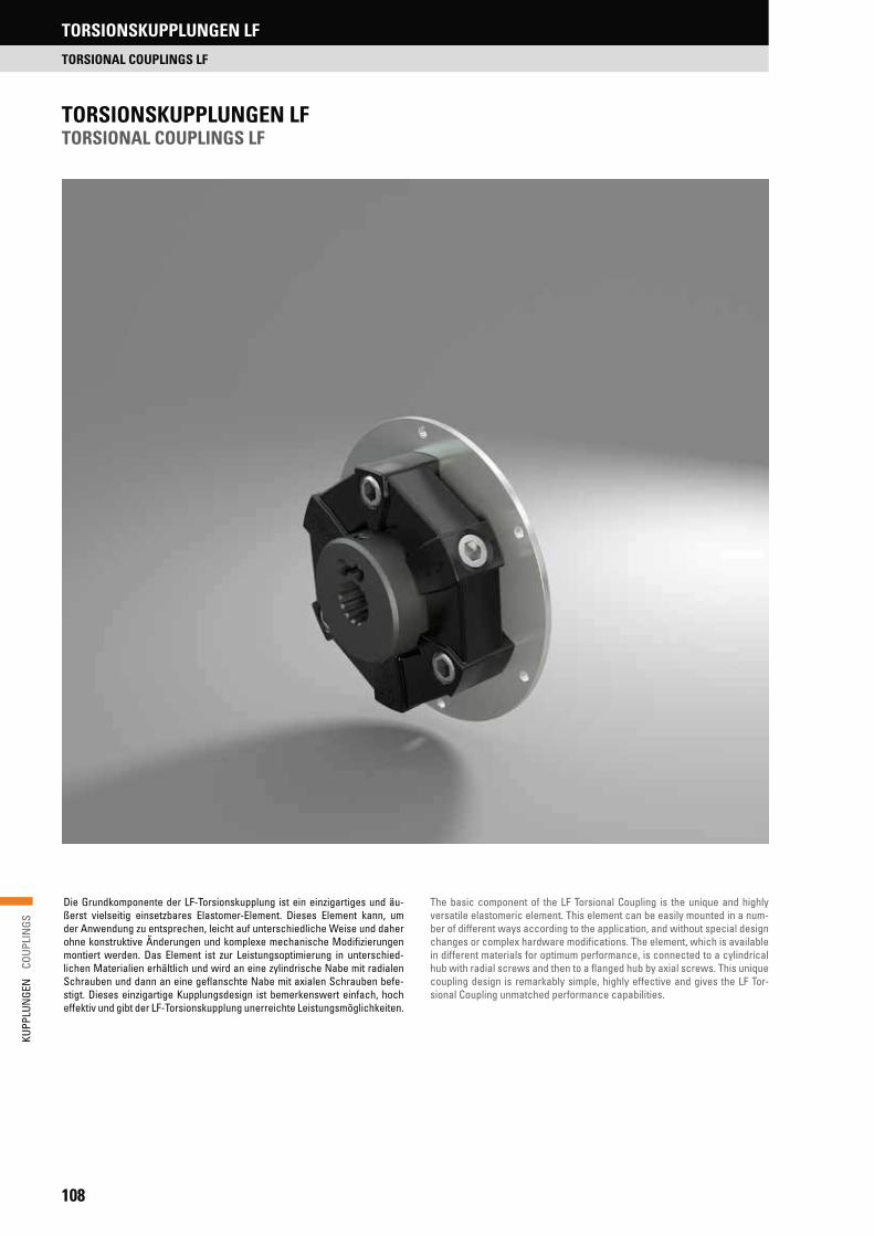
108
KUPP
LUN
GEN
C
OUPL
INGS
TORSIONSKUPPLUNGEN LF
TORSIONAL COUPLINGS LF
TORSIONSKUPPLUNGEN LF TORSIONAL COUPLINGS LF
Die Grundkomponente der LF-Torsionskupplung ist ein einzigartiges und äu-ßerst vielseitig einsetzbares Elastomer-Element. Dieses Element kann, um der Anwendung zu entsprechen, leicht auf unterschiedliche Weise und daher ohne konstruktive Änderungen und komplexe mechanische Modifizierungen montiert werden. Das Element ist zur Leistungsoptimierung in unterschied-lichen Materialien erhältlich und wird an eine zylindrische Nabe mit radialen Schrauben und dann an eine geflanschte Nabe mit axialen Schrauben befe-stigt. Dieses einzigartige Kupplungsdesign ist bemerkenswert einfach, hoch effektiv und gibt der LF-Torsionskupplung unerreichte Leistungsmöglichkeiten.
The basic component of the LF Torsional Coupling is the unique and highly versatile elastomeric element. This element can be easily mounted in a num-ber of different ways according to the application, and without special design changes or complex hardware modifications. The element, which is available in different materials for optimum performance, is connected to a cylindrical hub with radial screws and then to a flanged hub by axial screws. This unique coupling design is remarkably simple, highly effective and gives the LF Tor-sional Coupling unmatched performance capabilities.

109
KUPP
LUN
GEN
C
OUPL
INGS
TORSIONSKUPPLUNGEN LF
TORSIONAL COUPLINGS LF
ParallelverlagerungParallel misalignment
WinkelverlagerungAngular misalignment
DrehweichTorsional soft
AxialverlagerungAxial misalignment
PRODUKTMERKMALEFEATURES
• Substantial shock, vibration, and misalignment capabilities• Fail-safe operation• Coupling allows blind connection of equipment• Low weight, low moment of inertia• Free from noise and electrically insulating• No lubrication, maintenance free• Oil, heat, and corrosion resistant elements (HYTREL®, ZYTEL®)• Easy to disconnect driver and driven without moving equipment
or coupling hubs• Unique air flow design assists in keeping components cool during operation• Short profile for tight engine housing, or shaft-to-shaft requirements• Professional application assistance and expertise worldwide• Various element materials for variation in torsional stiffness and
environmental conditions
• Elemente aus versch. Materialien für unterschiedliche Torsionssteifigkeiten und Beständigkeiten
• Großes Leistungsvermögen hinsichtlich Stoßbelastungen, Schwingungen und Wellenverlagerungen
• Die Kupplung ermöglicht eine Blindmontage an maschinellen Einrichtungen • Niedriges Gewicht und geringes Trägheitsmoment• Frei von Störungen und elektrisch isolierend• Keine Schmierung, wartungsfrei• Öl-, hitze- und korrosionsbeständige Kupplungselemente (HYTREL®, ZYTEL®)• Einzigartiges Luftströmungsdesign kühlt die Komponenten während des
Betriebs• Kurzes Profil für enge Abstände im Maschinengehäuse oder von Welle zu
Welle• Leicht zu montieren, keine speziellen Verbindungen, Werkzeuge oder
zeitraubende Montageverfahren• Fachmännische Anwendungsunterstützung und Begutachtung weltweit• Elemente aus verschiedenen Materialien für unterschiedliche Drehfeder-
steifigkeiten und Umgebungsbedingungen

110
KUPP
LUN
GEN
C
OUPL
INGS
LF-TORSIONSKUPPLUNGEN – MODELLKONFIGURATIONEN LF TORSIONAL COUPLINGS – MODEL CONFIGURATION
MODELL O UND O/S MODEL O AND O/S
Das Herz der LF-Torsionskupplung ist ein flexibles Element. Es sind keine Ver-bindungen, Spezialwerkzeuge oder profilierte Aufspannflansche für die Ele-mente erforderlich. Das Modell O/S ermöglicht eine schnelle Blindmontage der treibenden mit der angetriebenen Einheit und erlaubt ein freies Längsspiel.
The heart of the LF Torsional Coupling is the flexible element. This model is easily mounted to the customer’s application designs or customer provided shaft hubs. No bands, special tools, or contoured element clamping flanges are necessary. This model allows the customer to make his own shaft hubs from readily available steel bar stock.
MODELL 1 UND 1/S MODEL 1 AND 1/S
Diese Kupplung besteht aus dem flexiblen Standardelement (Modell 0) mit einer einfachen zylindrischen Stahlnabe. Dies erfüllt die Anwendungsbedin-gungen für die direkte Montage an Motorschwungscheiben, Riemenscheiben, Bremsscheiben und Zahnrädern. Die zylindrische Nabe ist mit verschiedenen Bohrungen (Normen: ANSI, DIN, JIS) in Zoll, metrisch, für Keilwellen oder kun-denspezifisch erhältlich.
Modell 1/S wird mit der für die S-Bauform spezifischen axialen Schraube (ähnlich einem Passstift) für eine schnelle Blindmontage des Antriebsstrangs gezeigt.
Consists of the standard flexible element (Model 0) with a simple steel cylin-drical hub. This satisfies the application requirements for mounting directly to engine flywheels, pulleys, brake discs, friction clutches, universal joints and gears. The cylindrical hub is available in a range of bores (Standard ANSI, DIN, JIS) inch, metric, spline and custom.
Model 1/S is shown with the S-style axial screw (similar to a dowel) for quick blind assembly of the drive package. The same element combinations avail-able in Model 1 are also available in the Model 1/S.
MODELL 2 UND 2/S MODEL 2 AND 2/S
Diese Kupplung ist dem oben gezeigten Modell 1 ähnlich, außer dass ein Kupplungsflansch hinzugefügt wurde, um Welle-zu-Welle-Verbindungen her-zustellen. Das Modell 2/S erlaubt eine Blindmontage der Kupplung. Die Kupp-lungselemente vom Type „S“ erlauben eine axiale Verschiebung der Kupplung.
Provides a complete shaft-to-shaft coupling in a range of sizes for all industrial power transmission applications. It is similar to Model 1 shown above, except a flanged hub is added to make the shaft to shaft connection. Model 2/S allows the drive package to be blind connected. As with all S-style models, free axial end float of equipment shafts is accomplished without harmful push-pull force.
Modell O und O/S Model O and O/S
Modell 2 und 2/S Model 2 and 2/S
Modell 1 und 1/S Model 1 and 1/S
Auf dieser und der folgenden Seite sehen Sie die Standardmodelle der LF-Torsionskupplung. Das einfache und einzigartige Design der LF Torsionskupp-lung erlaubt eine Vielzahl an Modellen aus Standardkomponenten, um jede mögliche Anwendungsanforderung abzudecken. Vom Motorschwungradge-häuse bis hin zur langen Distanz eines korrosiven Kühlturms – Lovejoy hat das optimale LF Torsionskupplungsmodell für Ihre Anwendung.
Shown on this and the next page are the standard LF Torsional Coupling mod-els. The simple, unique design of the LF Torsional Coupling permits this wide range of models, from common components, to meet each application require-ment. From engine flywheel housing or the long corrosive span of a cooling tower, Lovejoy has the optimum LF Torsional Coupling model avaible for your application.
TORSIONSKUPPLUNGEN LF
TORSIONAL COUPLINGS LF

111
KUPP
LUN
GEN
C
OUPL
INGS
Modell 3 und 3/S Model 3 and 3/S
Modell 6/S Model 6/S
Modell 6 Model 6
Modell 6B Model 6B
MODELL 3 UND 3/S MODEL 3 AND 3/S
Mit einer zusätzlichen Motorenschwungrad-Montageplatte wird Modell 1 oder 1/S zu einem Modell 3 oder 3/S. Dieses Modell ist für viele Standard-SAE-Schwungradgrößen erhältlich (siehe Seiten 123 und 124), wird aber auch auf Bestellung in anderen Größen angefertigt. Die zylindrische Nabe ist mit verschiedenen Verzahnungen nach ANSI (SAE) oder DIN sowie mit zylindri-scher Bohrung und Nut erhältlich. Wie bei den vorherigen Modellen sind auch hier unterschiedliche Elemente zur Anpassung der Drehfedersteifigkeit oder für bestimmte Umgebungsbedingungen verfügbar.
A Model 1 or 1/S, with the addition of an engine flywheel mounting plate, be-comes a Model 3 or 3/S. It is available in many standard SAE flywheel sizes (see pages 123 and 124) as well as made-to-order sizes. The standard cylindri-cal hub is available in a variety of ANSI (SAE), DIN, JIS spline bores as well as straight bores. As with the previous models, various standard flexible element materials are available for specific torsional, misalignment and environmental requirements.
MODELL 6, 6/S UND 6B VERSION MIT FLIEGENDER WELLEMODEL 6, 6/S AND 6B FLOATING SHAFTS VERSION
Die Kupplungen sind in kundenspezifischen Einbaulängen erhältlich. Modell 6/S hat ein freies Längsspiel ohne schädliche Zug-Druck-Belastungen. Modell 6B ist eine hochelastische Kupplung mit einer fliegenden Welle und genauen wartungsfreien Zentrierflanschen für Anwendungen mit großen Spannweiten und großen Verlagerungen und/oder hohen Drehzahlanforderungen.
Floating shafts are available in customer specified assembly length, with special corrosion and heat resistant elements and materials. This model sur-passes all other floating shaft designs in assembly, simplicity and reliability. Model 6/S accommodates free endplay without harmful push-pull reaction forces. Model 6B is a highly elastic floating shaft coupling with accurate, maintenance- free centering flanges for applications with long spans and high misalignment and/or speed requirements.
LF-TORSIONSKUPPLUNGEN – MODELLKONFIGURATIONEN LF TORSIONAL COUPLINGS – MODEL CONFIGURATION
TORSIONSKUPPLUNGEN LF
TORSIONAL COUPLINGS LF

112
KUPP
LUN
GEN
C
OUPL
INGS
LF-TORSIONSKUPPLUNGEN – FLEXIBLE ELEMENTE LF TORSIONAL COUPLINGS – FLEXIBLE ELEMENTS
GUMMI (HTR) RUBBER (HTR)
Die Kupplungselemente aus Naturgummi (HTR) sind in der Verdrehung weich und werden bei der Montage komprimiert. Komprimierter Gummi kann im Vergleich mit nichtkomprimierten Elementen bis zum fünffa-chen der Torsionsbelastung aufnehmen. Die LF-Torsionselemente aus Gummi verarbeiten wirksam Stöße, Verlagerungen und Vibrationen und geben keine schädlichen Radial- und Axialbelastungen an die ange-schlossenen Einheiten ab. Jedes Gummielement ist in unterschiedlichen Durometer-Härtegraden (Shore-A-Skala) von 50, 60 und 70 für besondere Torsionsvibrationsbedingungen lieferbar. Naturgummi-Elemente (HTR) haben einen Betriebsbereich von -40 °C bis 90 °C. Für höhere Temperaturanforderungen wenden Sie sich bitte an die technische Abteilung der R+L HYDRAULICS.
Rubber in compression can carry up to five times the amount of torque, as compared to non-compressed elements. The rubber LF Torsional elements effectively accommodate shock, misalignment, and vibration and do not exert harmful radial and axial forces on the connected equipment. Each rubber element mate-rial is available in various durometer hardness (Shore A Scale) of 50, 60, and 70 for particular torsional vibration requirements. Natural rubber (HTR) elements have an operating range of -40 °C to 90 °C. Consult R+L HYDRAULICS Engineering for higher temperature requirements.
HYTREL® ELEMENTE (HY) HYTREL® ELEMENTS (HY)
Hergestellt aus HYTREL®, einer Elastomer-Verbindung von DuPontTM, sind diese Elemente etwa 20 mal steifer als Naturgummi und wurden primär für die Verwendung in flanschmontierten Verbrennungsmotor/Hydraulikpumpen-Anwendungen entwickelt. Diese Anwendungen erfordern gewöhnlich eine zuverläs-sige Kupplungsleistung in heißen und öligen Umgebungen. HYTREL®-Elemente arbeiten effizient in einem Temperaturbereich von -50 °C bis 120 °C. Eine Torsionskupplung mit HYTREL®-Element verschiebt schäd-liche Vibrationsresonanzfrequenzen über den Betriebsdrehzahlbereich der Hydraulik-Pumpenbaugruppe hinaus. Das einzigartige Design des Elements reduziert zudem schädliche axiale Reaktionsbelastungen.
LF Torsional elements are made of a HYTREL® elastomer compound from DuPontTM. These elements are torsionally much stiffer than natural rubber – about 20 times stiffer – and were developed for use primarily in combustion engine/hydraulic pump applications. These applications usually require reliable coupling performance in hot, oily environments. HYTREL® elements have 20% greater torque capacity compared to rubber elements and operate efficiently in the temperature range of -50 °C to 120 °C. The torsional coupling with the HYTREL® element places the harmful vibration resonance frequency above the operating speed range of the power package. The unique element design also reduces harmful axial reactionary forces.
ZYTEL® ELEMENTE (X) ZYTEL® ELEMENTS (X)
Diese torsionssteifen Elemente sind extrem robust und aus einer DuPontTM hochbelastbarer Elastomer-Verbindung ZYTEL® hergestellt. ZYTEL® ist sehr widerstandsfähig gegenüber Korrosion und chemischer Belastung. ZYTEL® Elemente können ohne eine Herabsetzung der Betriebswerte in Temperaturbereichen von -40 °C bis +150 °C eingesetzt werden. Der Aufbau dieser Elemente ergibt eine dreifache Torsionssteife im Vergleich zu den HYTREL®-Elementen. ZYTEL®-Elemente (X) zeigen weniger als 1° Verdrehwinkel beim Nenndrehmoment und sind absolut spielfrei.
This element is extremely rugged and made of Dupont's highly stressable ZYTEL® elastomeric compound. ZYTEL® has excellent resistance to most chemical attacks and corrosion. Operational temperature range is -40 °C to 150 °C without derating. This element composition is torsionally about three times stiffer than the HYTREL® elements. Maximum angular misalignment is 1°. ZYTEL® (X) elements exhibit less than 1° wind up at nominal torque and zero backlash.
TORSIONSKUPPLUNGEN LF
TORSIONAL COUPLINGS LF
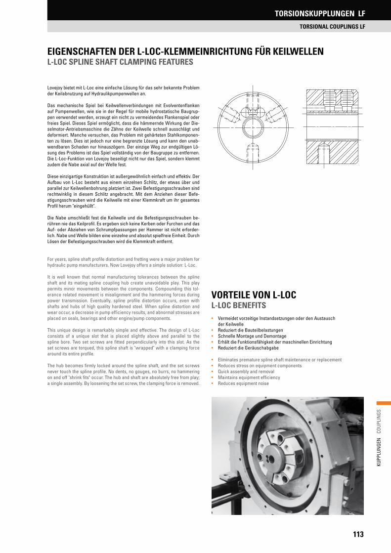
113
KUPP
LUN
GEN
C
OUPL
INGS
EIGENSCHAFTEN DER L-LOC-KLEMMEINRICHTUNG FÜR KEILWELLEN L-LOC SPLINE SHAFT CLAMPING FEATURES
Lovejoy bietet mit L-Loc eine einfache Lösung für das sehr bekannte Problem der Keilabnutzung auf Hydraulikpumpenwellen an.
Das mechanische Spiel bei Keilwellenverbindungen mit Evolventenflanken auf Pumpenwellen, wie sie in der Regel für mobile hydrostatische Baugrup-pen verwendet werden, erzeugt ein nicht zu vermeidendes Flankenspiel oder freies Spiel. Dieses Spiel ermöglicht, dass die hämmernde Wirkung der Die-selmotor-Antriebsmaschine die Zähne der Keilwelle schnell ausschlägt und deformiert. Manche versuchen, das Problem mit gehärteten Stahlkomponen-ten zu lösen. Dies ist jedoch nur eine begrenzte Lösung und kann den unab-wendbaren Schaden nur hinauszögern. Der einzige Weg zur endgültigen Lö-sung des Problems ist das Spiel vollständig von der Baugruppe zu entfernen. Die L-Loc-Funktion von Lovejoy beseitigt nicht nur das Spiel, sondern klemmt zudem die Nabe axial auf der Welle fest.
Diese einzigartige Konstruktion ist außergewöhnlich einfach und effektiv. Der Aufbau von L-Loc besteht aus einem einzelnen Schlitz, der etwas über und parallel zur Keilwellenbohrung platziert ist. Zwei Befestigungsschrauben sind rechtwinklig in diesem Schlitz angebracht. Mit dem Anziehen dieser Befe-stigungsschrauben wird die Keilwelle mit einer Klemmkraft um ihr gesamtes Profil herum "eingehüllt".
Die Nabe umschließt fest die Keilwelle und die Befestigungsschrauben be-rühren nie das Keilprofil. Es ergeben sich keine Kerben oder Furchen und das Auf- oder Abziehen von Schrumpfpassungen per Hammer ist nicht erforder-lich. Nabe und Welle bilden eine einzelne und absolut spielfreie Einheit. Durch Lösen der Befestigungsschrauben wird die Klemmkraft entfernt.
For years, spline shaft profile distortion and fretting were a major problem for hydraulic pump manufacturers. Now Lovejoy offers a simple solution: L-Loc.
It is well known that normal manufacturing tolerances between the spline shaft and its mating spline coupling hub create unavoidable play. This play permits minor movements between the components. Compounding this tol-erance related movement is misalignment and the hammering forces during power transmission. Eventually, spline profile distortion occurs, even with shafts and hubs of high quality hardened steel. When spline distortion and wear occur, a decrease in pump efficiency results, and abnormal stresses are placed on seals, bearings and other engine/pump components.
This unique design is remarkably simple and effective. The design of L-Loc consists of a unique slot that is placed slightly above and parallel to the spline bore. Two set screws are fitted perpendicularly into this slot. As the set screws are torqued, this spline shaft is "wrapped" with a clamping force around its entire profile.
The hub becomes firmly locked around the spline shaft, and the set screws never touch the spline profile. No dents, no gouges, no burrs, no hammering on and off "shrink fits" occur. The hub and shaft are absolutely free from play; a single assembly. By loosening the set screw, the clamping force is removed.
VORTEILE VON L-LOC L-LOC BENEFITS• Vermeidet vorzeitige Instandsetzungen oder den Austausch
der Keilwelle• Reduziert die Bauteilbelastungen• Schnelle Montage und Demontage• Erhält die Funktionsfähigkeit der maschinellen Einrichtung• Reduziert die Geräuschabgabe
• Eliminates premature spline shaft maintenance or replacement• Reduces stress on equipment components• Quick assembly and removal• Maintains equipment efficiency• Reduces equipment noise
TORSIONSKUPPLUNGEN LF
TORSIONAL COUPLINGS LF

114
KUPP
LUN
GEN
C
OUPL
INGS
Bei korrekter Auswahl und Bemessung dämpft die Lovejoy Torsionskupplung wirkungsvoll Vibrationen und gewährleistet, dass die Anlage, die von Die-sel, Benzin oder Erdgas-Kolbenmotoren angetrieben wird, nicht innerhalb der kritischen Frequenz betrieben wird. Um jedoch sicherzustellen, dass die Kupplung ihre Aufgabe wie vorgesehen erfüllt, sollte die Auswahl mittels einer Drehschwingungsanalyse verifiziert werden.
Die falsche Auswahl einer Kupplung in einer Motoranwendung führt häufig zu einem Kupplungsausfall oder einem Anlagenschaden. Wir empfehlen Ihnen die optimale Kupplung von R+L HYDRAULICS auswählen zu lassen.
Wir stellen sicher, dass die korrekte Kupplungsgröße und -steifheit nicht nur für das richtige nominale und maximale Drehmoment ausgewählt wird, son-dern auch für den schwer fassbaren Faktor eines ständig einwirkenden Vibra-tionsmoments, das sonst eine Elastomer-Kupplung schmelzen oder zerreißen und andere Systemkomponenten beschädigen könnte.
Zur Auslegung der Kupplung finden Sie auf unserer Website ein Arbeitsblatt, das Sie ausfüllen und per E-Mail an uns senden können.
Für die, die in ihren technischen Fähigkeiten sicher sind und die Torsions-analyse eines Systems verstehen und deshalb ihre eigene Kupplungsauswahl treffen wollen, stellen wir folgende essenzielle Richtlinien bereit.
When correctly sized and selected, the Lovejoy Torsional Coupling will ef-fectively dampen vibration and tune critical frequencies out of the operating range of systems driven by diesel, gasoline or natural gas reciprocating en-gines. But to make sure the coupling will do its job as intended, the selection should be verified with a torsional vibration analysis of the system.
Misapplication of the coupling in an engine application frequently leads to coupling failure or system damage. For these applications, we strongly urge that you let R+L HYDRAULICS make the coupling selection for you.
We will insure that the correct coupling size and stiffness is selected not only for proper nominal and maximum torque, but also for the elusive factor of con-tinuous vibratory torque which can otherwise melt or rupture an elastomeric coupling or damage other system components.
For designing the coupling you will find a worksheet on our website whichyou can send to R+L HYDRAULICS via e-mail.
For those confident in their technical abilities and understanding of system torsional analysis who prefer to make their own coupling selection, we pro-vide the following essential guidelines.
1. Choose a model that suits your drive arrangement using the descriptions of basic models given previously on pages 110 and 111.
• Model 3 or 3/S – For mounting directly to standard SAE flywheels.• Model 2 or 2/S – For shaft-to-shaft applications such as PTOs.
Also, the flanged hub can be modified to adapt to front damper pulleys.• Model 1 or 1/S – For connecting a shaft to a flange or non-standard
flywheel.• Model 6 – Various different universal floating shaft arrangements
available (see page 125)
2. Nominal torqueThe nominal torque transmitted though the coupling (TLN) must be no more than the nominal torque rating for the coupling (TKN) at any given operating temperature:
TKN TLN × St
where St is the temperature factor (Fig.1, p.119), and
TLN = 9555 . P/n , wherebyP [kW]: Drive powern [kW]: Speed
3. Peak torque pulsesThe magnitude of the maximum torque pulses that occur during operation (Tmax) at all operating temperatures must not exceed the maximum torque rating of the coupling (TKmax). These are short-duration transient pulses that would result from start-up, shock, or acceleration through a system reso-nance to reach operating speed. By definition, these pulses may occur over the life of the coupling 105 times in one direction of rotation, or 5 × 10⁴ times reversing.
TKmax Tmax × St
1. Wählen Sie ein Modell aus, das zu Ihrem Antriebssystem passt, indem Sie die vorab gegebenen Beschreibungen der Basismodelle auf den Seiten 110 und 111 berücksichtigen.
• Modell 3 oder 3/S – Für die direkte Montage auf SAE-Standard-schwungscheiben.
• Modell 2 oder 2/S – Für Welle-Welle-Anwendungen wie bei typischen Kraftübertragungen. Auch kann die Flanschnabe zur Anpassung an Dämpfungsscheiben modifiziert werden.
• Modell 1 oder 1/S – Für die Verbindung einer Welle mit einem Flansch oder einer Nicht-Standardschwungscheibe.
• Modell 6 – Es stehen verschiedene universelle Baugruppen mit fliegenden Wellen zur Verfügung (siehe Seite 125).
2. NenndrehmomentDas von der Kupplung übertragene Nenndrehmoment (TLN) darf nicht mehr als das Nenndrehmoment der Kupplung (TKN) bei der jeweiligen Betriebstem-peratur sein:
TKN TLN × St
wobei St der Temperaturfaktor (Abb.1, Seite 119) und
TLN = 9555 . P/n , wobeiP [kW]: Antriebsleistungn [kW]: Drehzahl
3. Drehmoment-ImpulsspitzenDie Magnitude der maximalen Drehmomentimpulse (Tmax), die über den ge-samten Betriebstemperaturbereich hinweg während des Betriebs auftreten, dürfen die maximale Drehmomentauslegung (TKmax) der Kupplung nicht über-schreiten. Dies sind kurzzeitige transiente Impulse, die vom Starten, von Stö-ßen oder von der Beschleunigung zur Erreichung der Betriebsdrehzahl durch eine Systemresonanz verursacht werden können. Per Definition können diese Impulse während der Lebensdauer der Kupplung 105 mal in eine der Drehrich-tungen oder 5 × 10⁴ mal in die andere Richtung auftreten.
TKmax Tmax × St
AUSWAHL DER TORSIONSKUPPLUNG FÜR VERBRENNUNGSMOTORANWENDUNGEN
TORSIONAL COUPLING SELECTION FOR INTERNAL COMBUSTION ENGINE APPLICATIONS
TORSIONSKUPPLUNGEN LF
TORSIONAL COUPLINGS LF

115
KUPP
LUN
GEN
C
OUPL
INGS
wobeinR = die kritische Resonanzdrehzahl des Systems [1/min],CTdyn = die dynamische Torsionssteife der Kupplung [Nm/rad],JA = das Massenträgheitsmoment der Antriebsseite [kg m²],undJL = das Massenträgheitsmoment der Lastseite [kg m²] sind.
In diesem Modell stellt die Kupplung eine Feder dar, welche die Torsions-schwingungen des Motors und der Schwungscheibe auf der einen und die der getriebenen Einheit auf der anderen Seite kontrolliert.
nR =60
CTdyn ×JA + JL
2 × i JA × JL
JA JL
CTdyn
Verwenden Sie die Werte der Drehfedersteifigkeiten aus der Leistungsdaten-tabelle (Seite 117). Massenträgheitswerte können von den betreffenden Mo-toren- oder Maschinenherstellern angefordert werden.
Im Allgemeinen sollten Dauerdrehzahlen für einen sicheren Betrieb mit nied-rigen Resonanzen das 1,5- bis 2-fache der hauptsächlichen kritischen Drehzahl betragen.
5. Dauerhaft zulässiges WechseldrehmomentDie Amplitude eines vom System generierten ständig schwingenden Wech-seldrehmoments (TW) darf die Werte der Kupplung (TKW) bei einer besonderen Dauerfrequenz [1/min] und Temperatur nicht überschreiten. Dieses Drehmo-ment ist der Grundlast (TLN) überlagert (koexistiert damit).
TKW TW × St × Sf
wobeiTKW = Kupplungsauslegung für ein dauerhaftes Wechseldrehmoment bei 10 Hz
undSf = der Frequenzfaktor, der die Betriebsfrequenz mit der Auslegung der
Kupplung bei 10 Hz in Verbindung bringt, ist (siehe Abb. 3. Seite 119).
Die Magnitude des ständig schwingenden Drehmoments (TW) hängt von dem Verstärkungsfaktor (V) ab, der auf dem Abstand der Betriebsdrehzahl im Dau-erzustand n von der Resonanzdrehzahl nR basiert:
6. Andere ErwägungenBeachten Sie die Leistungsdatentabellen, Abbildungen und Abmessungsta-bellen für die endgültige Kupplungsauswahl, damit die Maße (Außendurch-messer, Länge, Bohrungsmaße etc.), die Maximaldrehzahlen und die zuläs-sigen Verlagerungen den Anwendungsbedingungen entsprechen.
wherenR = the critical resonance speed of the system [1/min],CTdyn = the dynamic torsional stiffness of the coupling [Nm/rad],JA = the mass moment of inertia for the drive side [kg m²],andJL = the mass moment of inertia for the load side [kg m² ].
The coupling would be modeled as the spring controlling torsional oscillations of the engine and flywheel on one side and the driven equipment on the other:
Use the dynamic torsional stiffness values from the Performance Data table (p. 117). Mass moment of inertia values may be obtained from the respective engine and equipment manufacturers.
Generally, system steady-state operating speeds should be 1.5 to 2 times the major critical speed for safe, low-resonance operation.
5. Allowable continuously oscillating torqueThe amplitude of the continuously oscillating torque generated in the system (TW) must not exceed the coupling's rating (TKW) at a particular steady-state frequency [RPM] and temperature. This torque is superimposed on (co-exists with) the basic load (TLN).
TKW TW × St × Sf
whereTKW = coupling rating for continuously oscillating torque at 10 Hz
andSf = the frequency factor that relates the operating frequency to the
coupling’s 10 Hz rating (see fig. 3, p.119).
The magnitude of the continuously oscillating torque (TW) is dependent on an amplifying factor (V) based on the distance of the system steady-state operat-ing speed n from the resonance speed nR :
6. Other considerationsRefer to the Performance Data tables, figures, and dimension tables to make certain final coupling selection meets application constraints for envelope (O.D., length, bore dimensions, etc.), maximum speed limitations and allow-able misalignment.
V 1
(see fig. 4, p.119).|1-(n/nR )
2|
JA JL
CTdyn
4. Kritische Drehzahlen aufgrund der Resonanz bestimmenDie Kupplungssteife auswählen, sodass das System nicht im hohen Resonanz-bereich läuft, oder mit anderen Worten sicherstellen, dass normale Betriebs- und Leerlaufdrehzahlen sich nicht in der Nähe von kritischen Drehzahlen befinden.
Kritische Drehzahlen stehen in Beziehung mit der natürlichen Frequenz des Systems und der generierten Anzahl der Impulse oder Erregungen pro Um-drehung i (Reihenfolge). Zur Analyse ist die Anwendung möglichst auf ein 2-Massen-System zu reduzieren und nachfolgende Gleichung anzuwenden.
4. Determine critical speeds due to resonanceSelect coupling stiffness so that the system does not run at high resonance, or in other words, make sure normal running and idle speeds are not at or near critical speeds.
Critical speeds are related to the system natural frequency and the number of pulses or excitations generated per revolution i (order). For analysis, if pos-sible, reduce the application to a 2-mass system and apply the following equa-tion on next page.
nR =60
CTdyn ×JA + JL
2 × i JA × JL
V 1
(siehe Abb. 4, Seite 119).|1-(n/nR)2|
AUSWAHL DER TORSIONSKUPPLUNG FÜR VERBRENNUNGSMOTORANWENDUNGEN
TORSIONAL COUPLING SELECTION FOR INTERNAL COMBUSTION ENGINE APPLICATIONS
TORSIONSKUPPLUNGEN LF
TORSIONAL COUPLINGS LF

116
KUPP
LUN
GEN
C
OUPL
INGS
Während die LF-Torsionskupplung zur Lösung der speziellen Probleme im Zu-sammenhang mit Torsionsvibrationen bei Einheiten, die von Verbrennungsmo-toren angetrieben werden, entwickelt wurde, arbeitet diese Kupplung genau so gut bei allgemeinen industriellen Anwendungen. Verwenden Sie für An-wendungen mit Elektromotorantrieb oder andere Anwendungen ohne Motor folgendes einfaches Auswahlverfahren (siehe Seite 116) für motorgetriebene Anwendungen.
1. Wählen Sie ein Modell entsprechend den Beschreibungen der Ba-sismodelle auf den Seiten 110 und 111 aus, das Ihrer Antriebsanordnung entspricht:• Modell 2 – Das gebräuchlichste Modell für Welle-zu-Welle-
Anwendungen.• Modell 2/S – Für Welle-zu-Welle-Anwendungen, die ein freies Längsspiel
oder eine schnell steckbare Blindmontage benötigen.• Modell 1 oder 1/S – Für die Verbindung einer Welle mit einem Flansch
oder einer Schwungscheibe.
2. Wählen Sie das Elementenmaterial entsprechend den Anwendungsbe-dingungen aus. Am gebräuchlichsten wird das HTR-Element (Hochtempe-raturgummi) wegen der Vorzüge seiner hohen Flexibilität verwendet. Diese Eigenschaft liefert die zuvor beschriebenen Vorteile der Vibrations-, Stoß- und Geräuschdämpfung und eine hohe Verlagerungstoleranz.
Falls erforderlich liefert das ZYTEL®-Element eine starre Torsionsverbindung, die jedoch so flexibel ist, dass sie kleine Winkelverlagerungen toleriert. Die Anwendung des Modells 6 mit fliegender Welle erlaubt auch eine Parallelver-lagerung. Zudem ist das ZYTEL®-Material chemisch sehr resistent.
Beachten Sie bitte, dass das optionale HYTREL®-Element eine nahezu per-fekte Ausrichtung erfordert, was in den meisten Anwendungen nicht der Fall ist und wird daher nicht empfohlen, außer wenn das Element wie vorgese-hen an einer flanschmontierten Hydraulikpumpe an einem Motorschwung-rad eingesetzt wird.
3. Wählen Sie einen Betriebsfaktor aus der Tabelle auf Seite 119 für Ihre Anwendung aus.
Beispiel: Zentrifugalpumpe SF = 1,0
4. Bestimmen Sie die nominale Drehmomentanforderung für die Kupplung aus der angewandten Leistung ]PS] und der Drehzahl. Verwenden Sie, falls bekannt, das tatsächliche Drehmoment- oder die Leistungsanforderung der angetriebenen Einheit – andernfalls die nominale Motorleistung [kW].
Nehmen Sie nun die Leistungsdatentabelle und wählen Sie eine Kupplungs-größe aus, die für eine Leistung gleich oder größer dem Drehmoment der An-wendung multipliziert mit dem Betriebsfaktor ausgelegt ist:
Beispiel:Zentrifugalpumpe mit einer Leistungsaufnahme von10 kW bei 1500 [1/min].10 kW x 1.0 x 9555 / (1500 [1/min]) = 64 Nm
LT-Torsionskupplungsgröße LF8 verwenden
5. Andere ErwägungenBeachten Sie die Leistungsdatentabellen, Abbildungen und Abmessungsta-bellen zur endgültigen Kupplungsauswahl, die den Anwendungsbedingungen bzgl. der Maße (Außendurchmesser, Länge, Bohrungsmaße etc.) und der ma-ximalen Drehzahl entsprechen.
While the LF Torsional Coupling was developed to solve the unique problems associated with torsional vibration in equipment driven by internal combustion engines, the coupling works equally well in general industrial applications. For these electric motor-powered and other non-engine applications, use the following simple selection procedure (Refer to page 116 for engine-driven applications).
1. Choose a model that suits your drive arrangement using the descriptions of basic models given previously on pages 110 and 111:• Model 2 – Most common for shaft-to-shaft applications.• Model 2/S – For shaft to shaft applications that require free end-float
or quick, blind "plugin" assembly.• Model 1 or 1/S – For connecting a shaft to a flange or flywheel.
2. Choose element material consistent with application requirements. Most commonly, the HTR (hightemperature rubber) element is used for virtue of its high flexibility. This feature provides the previously mentioned benefits of vi-bration and shock damping, noise silencing, and a high tolerance for misalign-ment.
When required, the ZYTEL® element provides a torsionally rigid connection yet is still flexible in terms of accommodating small angular misalignments. Use of the floating-shaft Model 6 version will allow for parallel misalignment as well. The ZYTEL® material is also very chemical resistant.
Please note that the optional HYTREL® element requires almost perfect alignment which is unlikely in most applications and is not recommended, except when used as intended on a flange-mounted hydraulic pump to an engine flywheel.
3. Choose a service factor from the chart on page 119 for your application.
Example: Centrifugal pump SF = 1.0
4. Determine nominal torque requirement for coupling from application horse-power and speed. Use the actual torque or horsepower requirement for the driven equipment if known. Otherwise, use the rated motor power [kW].
Now, using the Performance Data table, select a coupling size with a rating equal to or greater than the application torque multiplied by the service factor:
Example:Centrifugal pump using 10 kW at 1500 [1/min].10 kW x 1.0 x 9555 / (1500 [1/min]) = 64 Nm
use LT Torsional size LF8
5. Other considerationsRefer to the Performance Data tables, figures, and dimension tables to make certain final coupling selection meets application constraints for envelope (O.D., length, bore dimensions, etc.), and maximum speed limitations.
TKN [Nm] P [kW] x SF x 9555
n [1/min]TKN [Nm]
P [kW] x SF x 9555
n [1/min]
AUSWAHL DER TORSIONSKUPPLUNG FÜR ALLGEMEINE INDUSTRIEANWENDUNGEN
TORSIONAL COUPLINGS SELECTION FOR GENERAL INDUSTRIAL APPLICATIONS
TORSIONSKUPPLUNGEN LF
TORSIONAL COUPLINGS LF
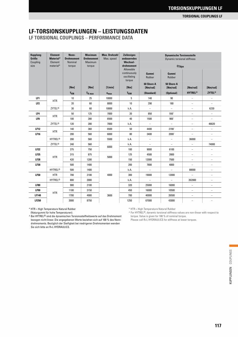
117
KUPP
LUN
GEN
C
OUPL
INGS
LF-TORSIONSKUPPLUNGEN – LEISTUNGSDATEN LF TORSIONAL COUPLINGS – PERFORMANCE DATA
KupplungGrößeCouplingsize
ElementMaterial*Element
material*
Nenn-Drehmoment
Nominaltorque
[Nm]
MaximumDrehmoment
Maximumtorque
[Nm]
Max. DrehzahlMax. speed
[1/min]
Zulässiges andauerndes
Wechsel-drehmoment
Allowable continuously
oscillatingtorque
[Nm]
Dynamische Torsionssteife Dynamic torsional stiffness
CTdyn
Gummi Rubber
Gummi Rubber
60 Shore A[Nm/rad]
50 Shore A[Nm/rad] [Nm/rad] [Nm/rad]
TKN TK max nmax TKW (Standard) (Optional) HYTREL® ZYTEL®
LF1HTR
10 25 10000 5 140 90 – –
LF2 20 60 8000 10 290 180 – –
ZYTEL® 30 60 10000 k.A. – – – 6230
LF4HTR
50 125 7000 20 850 550´ – –
LF8 100 280 6500 40 1500 900´ – –
ZYTEL® 120 280 7000 k.A. – – – 46820
LF12HTR
140 360 6500 50 4400 2700´ – –
LF16 200 560 6000 80 3400 2000´ – –
HYTREL® 200 560 5500 k.A. – – 36000 –
ZYTEL® 240 5606000
k.A. – – – 74000
LF22
HTR
275 750 100 9000 6100 – –
LF25 315 8755000
125 4500 2800 – –
LF28 420 1200 150 12000 7500 – –
LF30 500 1400
4000
200 7800 4800 – –
HYTREL® 500 1400 k.A. – – 88000 –
LF50 HTR 700 2100 300 19000 12000 – –
HYTREL® 800 2000 k.A. – – 262000 –
LF80
HTR
900 2100 320 25000 16000 – –
LF90 1100 3150
3600
450 16000 10500 – –
LF140 1700 4900 700 40000 26500 – –
LF250 3000 8750 1250 67000 43000 – –
* HTR = High Temperature Natural Rubber (Naturgummi für hohe Temperaturen).
^ Bei HYTREL® sind die dynamischen Torsionssteifheitswerte auf das Drehmoment bezogen nicht linear. Die angegebenen Werte beziehen sich auf 100 % des Nenn-drehmoments. Bezüglich der Steifigkeit bei niedrigeren Drehmomenten wenden Sie sich bitte an R+L HYDRAULICS.
* HTR = High Temperature Natural Rubber^ For HYTREL®, dynamic torsional stiffness values are non-linear with respect to
torque. Value is given for 100 % of nominal torque. Please call R+L HYDRAULICS for stiffness at lower torques.
TORSIONSKUPPLUNGEN LF
TORSIONAL COUPLINGS LF

118
KUPP
LUN
GEN
C
OUPL
INGS
LF-TORSIONSKUPPLUNGEN – LEISTUNGSDATENLF TORSIONAL COUPLINGS – PERFORMANCE DATA
Kupplung GrößeCouplingsize
Element Material*Element
material*
Max. zulässige Verlagerung**Max. allowable misalignment**
VerdrehwinkelWind up (angle of twist)
Statische SteifheitStatic stiffness
Winkel Angular
[°]
ParallelParallel
[mm]
Axial (Längsspiel)Axial (end float)
[mm]
Bei Nenn-Drehmoment
At nominaltorque
[°]
Bei max.Drehmoment
At max.torque
[°]
Axial Axial
RadialRadial
WinkelAngular
Kw Kr Standard KaS-Bauform***
S-Style***[N/mm]
Ca[N/mm]
Cr[N/°] Cw
LF1HTR 3
1.5 +/-2.0 +4.6/-2.06 17
38150 0.3
LF2 1.5 +/-3.0 +3.0/-3.0 22
ZYTEL® 1 0.1 +/-0.5 +3.0/-0.5 – –
LF4HTR 3
1.5 +/-3.0 +4.3/-3.05
1275 500
2.4
LF8 2.0 +/-4.0 +5.0/-4.0 14 3.6
ZYTEL® 1 0.1 +/-0.5 +5.0/-0.5 – –
LF12HTR
2 2.0 +/-3.0 +5.0/-4.0 3 7.5 250 1000 9.0
LF16 3 2.0 +/-5.0 +5.8/-5.0 5 14 100 500 5.0
HYTREL® 0 0 +3.0/-2.0 – –
ZYTEL® 1 0.1 +/-0.5 +5.8/-0.5 – –
LF22
HTR
2 2.0 +/-3.0 +5.8/-5.0 3 7.5 500 1300 12.0
LF25 3 2.0 +/-5.0 +6.6/-5.0 5 14 140 600 7.0
LF28 2 2.0 +/-3.0 +6.6/-5.0 3 7.5 550 1400 17.0
LF30 3 2.0 +/-5.0 +6.6/-5.0 5 14 190 750 9.0
HYTREL® 0 0 +3.0/-2.0 – –
LF50 HTR 3 2.0 +/-5.0 +6.6/-5.0 3 7.5 650 2200 26.0
HYTREL® 0 0 +3.0/-2.0 – –
LF80
HTR
2 1.5 +/-5.0 +6.6/-3.0 3 7.5 850 2900 34.0
LF90 3 2.0 +/-5.0 +8.6/-5.0 5 14 220 1000 17.0
LF1402
2.0 +/-5.0 +8.6/-5.03 7.5
650 2300 38.0
LF250 2.0 +/-5.0 +10.0/-5.0 1150 4100 68.0
* HTR = High Temperature Rubber (Gummi für hohe Temperaturen).** Die zulässigen Winkel- und Parallelverlagerungen sind von der Drehzahl
abhängig und bei Gummielementen sollten diese der Abb. 2 auf Seite 119 entsprechend justiert werden. HYTREL®-Elemente sind nur für An-wendungen geeignet, bei denen die angetriebene Komponente mit dem Antrieb für die notwendige perfekte Ausrichtung mit einer Führung ver-bunden ist (z. B. eine an das Motorschwungradgehäuse angeflanschte Hydraulikpumpe).
*** Die S-Bauform ist axial verschiebbar, ohne dass eine axiale Belastung der angeschlossenen Einheiten entsteht. Mit S-Bauform-Befestigungs-muffen in Sonderlängen kann zudem das zulässige Längsspiel vergrößert werden.
* HTR = High Temperature Rubber** Angular and parallel misalignment values are dependent on speed, and
for rubber elements, they should be adjusted according to figure 2 on page 119. HYTREL® elements are only for applications where the driven component is piloted to the driver for essentially perfect alignment (i.e. hydraulic pump flange-mounted to engine flywheel housing)
*** The "S-Style" design is not constrained axially and thus allows the hubs to move apart without creating axial force on the connected equipment. Special length S-Style fastener sleeves can further increase the allow-able end float.
TORSIONSKUPPLUNGEN LF
TORSIONAL COUPLINGS LF
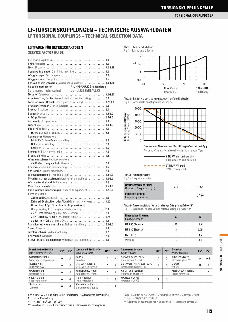
119
KUPP
LUN
GEN
C
OUPL
INGS
LF-TORSIONSKUPPLUNGEN – TECHNISCHE AUSWAHLDATEN LF TORSIONAL COUPLINGS – TECHNICAL SELECTION DATA
LEITFADEN FÜR BETRIEBSFAKTOREN SERVICE FACTOR GUIDE
Rührwerke Agitators . . . . . . . . . . . . . . . . . . . . . . . . . . . . . . . . . . . . . . . . . . 1.0Kneter Beaters . . . . . . . . . . . . . . . . . . . . . . . . . . . . . . . . . . . . . . . . . . . . . . 1.5Lüfter Blowers . . . . . . . . . . . . . . . . . . . . . . . . . . . . . . . . . . . . . . . . . . . . . . . 1.0-1.25Getränkefüllanlagen Can filling machinery . . . . . . . . . . . . . . . . . . . . . . 1.0Waggonkipper Car dumpers . . . . . . . . . . . . . . . . . . . . . . . . . . . . . . . . . . . 2.5Waggonwinden Car pullers . . . . . . . . . . . . . . . . . . . . . . . . . . . . . . . . . . . . 1.5Schraubenkompressoren Compressors (screws) . . . . . . . . . . . . . . . . 1.0-1.25Kolbenkompressoren R+L HYDRAULICS konsultieren Compressors (reciprocating) consult R+L HYDRAULICSFörderer Conveyors . . . . . . . . . . . . . . . . . . . . . . . . . . . . . . . . . . . . . . . . . . 1.0-1.25Arbeitswalzen, Rüttler Live roll, shaker & reciprocating . . . . . . . . . . . 3.0Förderer (rauer Betrieb) Conveyors (heavy duty) . . . . . . . . . . . . . . . . . 1.25-2.5Krane und Winden Cranes & hoists . . . . . . . . . . . . . . . . . . . . . . . . . . . . . 2.0Brecher Crushers . . . . . . . . . . . . . . . . . . . . . . . . . . . . . . . . . . . . . . . . . . . . 3.0Bagger Dredges . . . . . . . . . . . . . . . . . . . . . . . . . . . . . . . . . . . . . . . . . . . . . 1.5-2.0Aufzüge Elevators . . . . . . . . . . . . . . . . . . . . . . . . . . . . . . . . . . . . . . . . . . . . 1.5-2.0Verdampfer Evaporators . . . . . . . . . . . . . . . . . . . . . . . . . . . . . . . . . . . . . . 1.0Lüfter Fans . . . . . . . . . . . . . . . . . . . . . . . . . . . . . . . . . . . . . . . . . . . . . . . . . . 1.0-1.5Speiser Feeders . . . . . . . . . . . . . . . . . . . . . . . . . . . . . . . . . . . . . . . . . . . . . 1.0 Hubkolben Reciprocating . . . . . . . . . . . . . . . . . . . . . . . . . . . . . . . . . . . 2.5Generatoren Generators Nicht für Schweißen Not welding . . . . . . . . . . . . . . . . . . . . . . . . . . . 1.0 Schweißen Welding . . . . . . . . . . . . . . . . . . . . . . . . . . . . . . . . . . . . . . . 2.0 Lift Hoist . . . . . . . . . . . . . . . . . . . . . . . . . . . . . . . . . . . . . . . . . . . . . . . . . . 1.5Hammermühlen Hammer mills . . . . . . . . . . . . . . . . . . . . . . . . . . . . . . . . . 2.0Brennöfen Kilns . . . . . . . . . . . . . . . . . . . . . . . . . . . . . . . . . . . . . . . . . . . . . . 1.5Waschmaschinen Laundry washers mit Drehrichtungsumkehr Reversing . . . . . . . . . . . . . . . . . . . . . . . . . 2.0Deckentransmission Line shafting . . . . . . . . . . . . . . . . . . . . . . . . . . . . . . 1.5Sägewerke Lumber machinery . . . . . . . . . . . . . . . . . . . . . . . . . . . . . . . . . 2.0Werkzeugmaschinen Machine tools . . . . . . . . . . . . . . . . . . . . . . . . . . . . 1.5-2.0Metallformungsmaschinen Metal forming machines . . . . . . . . . . . . . . 1.5-2.5Walzwerke (drehend) Mills, rotary type . . . . . . . . . . . . . . . . . . . . . . . . . 2.0Mischmaschinen Mixers . . . . . . . . . . . . . . . . . . . . . . . . . . . . . . . . . . . . . . 1.5-1.8Papiermühlen-Einrichtungen Paper mills equipment . . . . . . . . . . . . . . 1.2-2.0Pumpen Pumps Zentrifugal Centrifugal . . . . . . . . . . . . . . . . . . . . . . . . . . . . . . . . . . . . . 1.0 Zahnrad, Drehkolben oder Flügel Gear, rotary or vane . . . . . . . . . . 1.25 Hubkolben. 1 Zyl., Einfach- oder Doppelwirkung Reciprocating 1 Cyl. single or double acting . . . . . . . . . . . . . . . . . . . 2.0 2 Zyl. Einfachwirkung 2 Cyl. single acting . . . . . . . . . . . . . . . . . . . . . 2.0 2 Zyl. Doppelwirkung 2 Cyl. double acting . . . . . . . . . . . . . . . . . . . . . 1.75 3 oder mehr Zyl. 3 or more Cyl. . . . . . . . . . . . . . . . . . . . . . . . . . . . . . . 1.5Gummiverarbeitungsmaschinen Rubber machinery . . . . . . . . . . . . . . 2.0-2.5Stoker Stokers . . . . . . . . . . . . . . . . . . . . . . . . . . . . . . . . . . . . . . . . . . . . . . . 1.0Textilmaschinen Textile machinery . . . . . . . . . . . . . . . . . . . . . . . . . . . . . 1.2Bauwinden Windlass . . . . . . . . . . . . . . . . . . . . . . . . . . . . . . . . . . . . . . . . . 2.0Holzverarbeitungsmaschinen Woodworking machinery . . . . . . . . . . . 1.0
Abb. 1 - TemperaturfaktorFig. 1 - Temperature factor
0.5
1
1.5
2
30 50 70 90
* Nur HTR* HTR only
Grad CelciusDegrees C
S t
Code: A = little or no effect; B = moderate effect; C = severe effect* HY = HYTREL® ZY = ZYTEL®
** Additives in antifreeze may attack these elastomers severely.
Kodierung: A = kleine oder keine Einwirkung, B = moderate Einwirkung, C = starke Einwirkung* HY = HYTREL® ZY = ZYTEL®
** Zusätze im Frostschutz können diese Elastomere stark angreifen.
Abb. 4 - Resonanzfaktor Vr und relativer Dämpfungsfaktor Fig. 4 - Resonance factor Vr and relative damping factor
Abb. 2 - Zulässige Verlagerung bezogen auf die DrehzahlFig. 2 - Permissible misalignment vs. speed
Betri
ebsd
rehz
ahl (
U/m
in)
Oper
atin
g Sp
eed
(RPM
)
Prozent des Nennwertes für zulässigen Versatz bei TKN
Percent of rating for allowable misalignment at TKN
HTR (Winkel und parallel)HTR (angular and parallel)
ZYTEL® (Winkel)ZYTEL® (angular)
Öl und HydraulikfluidsOils & hydraulic fluids
HY* ZY*Lösungen & TreibstoffeSolvents & fuels
HY* ZY* Säuren und LaugenAcids & bases
HY* ZY* SonstigesMiscellaneous
HY* ZY*
AutomatikgetriebeAutomatic transmissions A A Benzin
Gasoline A A Schwefelsäure (20 %) Sulfuric acid (20 %) A C Athylenglykol **
Ethylene glycol** A A, B
Fluidtyp A& F Fluid type A & F A A Nujol, JP4-Kerosin
Nujol, JP4 kerosene A A Chlorwasserstoffsäure (20 %)Hydrochloric acid(20 %) B C Dampf
Steam B B
Hydraulikfluid Hydraulic fluid A A Halokarbone, Freon
Halocarbons, Freon A A Kalium oder NatriumPotassium or sodium
Flüssiges AmmoniakLiquid ammonia A
Phosphatester Phosphate ester A A Trichloräthylen
Trichlorethylene C C Hydroxide (20 %)Hydroxide (20 %) A B
SchmierölLube oil A A Karbontetrachlorid
Carbon tetrachloride B A
Elastisches ElementElastic element Vr
HTR 50 Shore A 10 0.6
HTR 60 Shore A 8 0.78
HYTREL® – 0.5
ZYTEL® – 0.4
Abb. 3 - FrequenzfaktorFig. 3 - Frequency factor
Betriebsfrequenz f [Hz]Operating frequency f [Hz]
≤10 >10
Frequenzfaktor sfFrequency factor sf
1 √ f/10
TORSIONSKUPPLUNGEN LF
TORSIONAL COUPLINGS LF
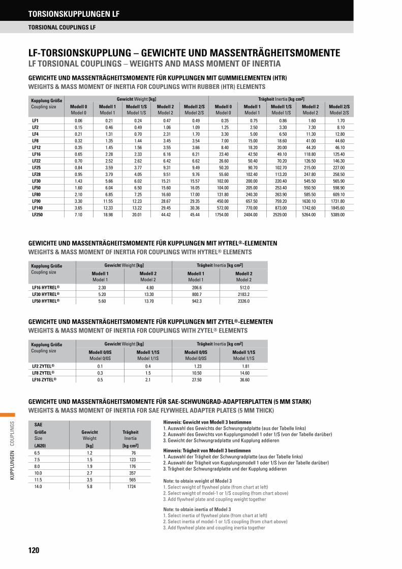
120
KUPP
LUN
GEN
C
OUPL
INGS
LF-TORSIONSKUPPLUNG – GEWICHTE UND MASSENTRÄGHEITSMOMENTELF TORSIONAL COUPLINGS – WEIGHTS AND MASS MOMENT OF INERTIA
GEWICHTE UND MASSENTRÄGHEITSMOMENTE FÜR KUPPLUNGEN MIT HYTREL®-ELEMENTENWEIGHTS & MASS MOMENT OF INERTIA FOR COUPLINGS WITH HYTREL® ELEMENTS
GEWICHTE UND MASSENTRÄGHEITSMOMENTE FÜR SAE-SCHWUNGRAD-ADAPTERPLATTEN (5 MM STARK)WEIGHTS & MASS MOMENT OF INERTIA FOR SAE FLYWHEEL ADAPTER PLATES (5 MM THICK)
Hinweis: Gewicht von Modell 3 bestimmen1. Auswahl des Gewichts der Schwungradplatte (aus der Tabelle links)2. Auswahl des Gewichts von Kupplungsmodell 1 oder 1/S (von der Tabelle darüber)3. Gewicht der Schwungradplatte und Kupplung addieren
Hinweis: Trägheit von Modell 3 bestimmen1. Auswahl der Trägheit der Schwungradplatte (aus der Tabelle links)2. Auswahl der Trägheit von Kupplungsmodell 1 oder 1/S (von der Tabelle darüber)3. Trägheit der Schwungradplatte und der Kupplung addieren
Note: to obtain weight of Model 31. Select weight of flywheel plate (from chart at left)2. Select weight of model-1 or 1/S coupling (from chart above)3. Add flywheel plate and coupling weight together
Note: to obtain inertia of Model 31. Select inertia of flywheel plate (from chart at left)2. Select inertia of model-1 or 1/S coupling (from chart above)3. Add flywheel plate and coupling inertia together
Kupplung GrößeCoupling size
Gewicht Weight [kg] Trägheit Inertia [kg cm2]
Modell 1Model 1
Modell 2Model 2
Modell 1Model 1
Modell 2Model 2
LF16 HYTREL® 2.30 4.80 206.6 512.0LF30 HYTREL® 5.20 13.30 800.7 2183.2LF50 HYTREL® 5.60 13.70 942.3 2326.0
Kupplung GrößeCoupling size
Gewicht Weight [kg] Trägheit Inertia [kg cm2]
Modell 0/0SModel 0/0S
Modell 1/1SModel 1/1S
Modell 0/0SModel 0/0S
Modell 1/1SModel 1/1S
LF2 ZYTEL® 0.1 0.4 1.23 1.81LF8 ZYTEL® 0.3 1.5 10.50 14.60LF16 ZYTEL® 0.5 2.1 27.50 36.60
Kupplung GrößeCoupling size
Gewicht Weight [kg] Trägheit Inertia [kg cm2]
Modell 0Model 0
Modell 1Model 1
Modell 1/SModel 1/S
Modell 2Model 2
Modell 2/SModel 2/S
Modell 0Model 0
Modell 1Model 1
Modell 1/SModel 1/S
Modell 2Model 2
Modell 2/SModel 2/S
LF1 0.06 0.21 0.24 0.47 0.49 0.35 0.75 0.86 1.60 1.70LF2 0.15 0.46 0.49 1.06 1.09 1.25 2.50 3.30 7.30 8.10LF4 0.21 1.31 0.70 2.31 1.70 3.30 5.00 6.50 11.30 12.80LF8 0.32 1.35 1.44 3.45 3.54 7.00 15.00 18.60 41.00 44.60LF12 0.35 1.45 1.56 3.55 3.66 8.40 18.20 20.00 44.20 46.10LF16 0.65 2.28 2.33 6.16 6.21 23.40 42.50 49.10 118.80 125.40LF22 0.70 2.52 2.62 6.42 6.62 26.60 50.40 70.20 126.50 146.30LF25 0.84 3.59 3.77 9.31 9.49 50.20 90.70 102.70 215.00 227.00LF28 0.95 3.79 4.05 9.51 9.76 55.60 102.40 113.20 247.80 258.50LF30 1.43 5.66 6.02 15.21 15.57 102.00 200.00 220.40 545.50 565.90LF50 1.60 6.04 6.50 15.60 16.05 104.00 205.00 253.40 550.50 598.90LF80 2.10 6.85 7.25 16.60 17.00 131.80 240.30 263.90 585.50 609.10LF90 3.30 11.55 12.23 28.67 29.35 450.00 657.50 759.20 1630.10 1731.80LF140 3.65 12.33 13.22 29.45 30.36 572.00 770.00 873.00 1742.60 1845.60LF250 7.10 18.98 20.01 44.42 45.44 1754.00 2404.00 2529.00 5264.00 5389.00
SAE
Größe Size
Gewicht Weight
Trägheit Inertia
(J620) [kg] [kg cm2]6.5 1.2 767.5 1.5 1238.0 1.9 17610.0 2.7 35711.5 3.5 56514.0 5.8 1724
GEWICHTE UND MASSENTRÄGHEITSMOMENTE FÜR KUPPLUNGEN MIT ZYTEL®-ELEMENTENWEIGHTS & MASS MOMENT OF INERTIA FOR COUPLINGS WITH ZYTEL® ELEMENTS
GEWICHTE UND MASSENTRÄGHEITSMOMENTE FÜR KUPPLUNGEN MIT GUMMIELEMENTEN (HTR)WEIGHTS & MASS MOMENT OF INERTIA FOR COUPLINGS WITH RUBBER (HTR) ELEMENTS
TORSIONSKUPPLUNGEN LF
TORSIONAL COUPLINGS LF
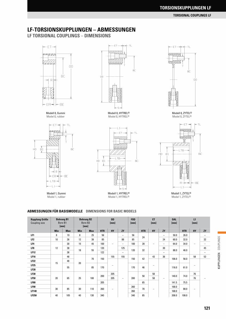
121
KUPP
LUN
GEN
C
OUPL
INGS
LF-TORSIONSKUPPLUNGEN – ABMESSUNGEN LF TORSIONAL COUPLINGS – DIMENSIONS
Modell 0, GummiModel 0, rubber
Modell 0, ZYTEL®
Model 0, ZYTEL®Modell 0, HYTREL®
Model 0, HYTREL®
Modell 1, Gummi Model 1, rubber
Modell 1, ZYTEL®
Model 1, ZYTEL®Modell 1, HYTREL®
Model 1, HYTREL®
ABMESSUNGEN FÜR BASISMODELLE DIMENSIONS FOR BASIC MODELS
Kupplung GrößeCoupling size
Bohrung B1Bore B1
[mm]
Bohrung B2Bore B2
[mm]
OD[mm]
FOD[mm]
ET[mm]
OAL[mm]
L1 [mm]
Min Max Min Max HTR HY ZY HTR HY ZY HTR HY ZY
LF1 8 19 8 25 56
–
– 5624
–
– 50.0 26.0
–
–
LF2 10 26 12 38 85 88 85 24 60.0 32.0 32
LF4
12
30 15 45 100 – 100 28 – 64.0 34.0 –
LF8 3818 55
120 125120 32
3088.0 46.0
45
LF12 38 122 – – –
LF16
15
48
20
70 150155 155
150 4243 36
106.0 56.058 53
LF22 48
–
–
–
–
–
–
LF2555 85 170 170 46 116.0 61.0
LF28
LF30
20 65 25 100200
205
20058
58140.0 74.0
76
LF50 205 58 76
LF80 205
–
65
–
141.5 75.5
–LF90
30 85 30 110 260260
70168.0
88.0LF140 260 168.0
LF250 40 105 40 130 340 340 85 208.0 108.0
TORSIONSKUPPLUNGEN LF
TORSIONAL COUPLINGS LF
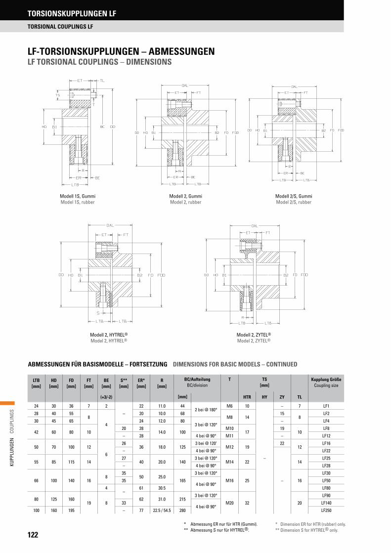
122
KUPP
LUN
GEN
C
OUPL
INGS
LF-TORSIONSKUPPLUNGEN – ABMESSUNGEN LF TORSIONAL COUPLINGS – DIMENSIONS
Modell 1S, GummiModel 1S, rubber
Modell 2/S, GummiModel 2/S, rubber
Modell 2, GummiModel 2, rubber
Modell 2, HYTREL®
Model 2, HYTREL®Modell 2, ZYTEL®
Model 2, ZYTEL®
ABMESSUNGEN FÜR BASISMODELLE – FORTSETZUNG DIMENSIONS FOR BASIC MODELS – CONTINUED
* Abmessung ER nur für HTR (Gummi).** Abmessung S nur für HYTREL®.
* Dimension ER for HTR (rubber) only.** Dimension S for HYTREL® only.
LTB[mm]
HD[mm]
FD[mm]
FT[mm]
BE[mm]
S**[mm]
ER*[mm]
R[mm]
BC/AufteilungBC/division
T TS[mm]
Kupplung GrößeCoupling size
[mm](+3/-2) HTR HY ZY TL
24 30 36 7 2
–
22 11.0 442 bei @ 180°
M6 10
–
– 7 LF1
28 40 558
4
20 10.0 68M8 14
158
LF2
30 45 65 24 12.0 803 bei @ 120°
– LF4
42 60 80 1020 28
14.0 100M10
1719
10LF8
– 28 4 bei @ 90° M11 – LF12
50 70 100 12
6
2636 18.0 125
3 bei @ 120‘M12 19
2212
LF16
– 4 bei @ 90°
–
LF22
55 85 115 1427
40 20.0 1403 bei @ 120°
M14 22 14LF25
– 4 bei @ 90° LF28
66 100 140 168
3550 25.0
165
3 bei @ 120°
M16 25 16
LF30
354 bei @ 90°
LF50
4–
61 30.5 LF80
80 125 16019 8
62 31.0 2153 bei @ 120°
M20 32 20
LF90
334 bei @ 90°
LF140
100 160 195 – 77 22.5 / 54.5 280 LF250
TORSIONSKUPPLUNGEN LF
TORSIONAL COUPLINGS LF
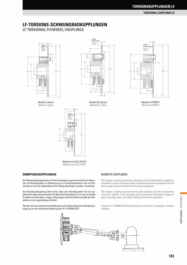
123
KUPP
LUN
GEN
C
OUPL
INGS
LF-TORSIONS-SCHWUNGRADKUPPLUNGENLF TORSIONAL FLYWHEEL COUPLINGS
DÄMPFUNGSKUPPLUNGEN
Die Dämpfungskupplung (auch Zwischenkupplung genannt) wird bei U-Gelen-ken und Kardanwellen zur Eliminierung von Torsionsvibrationen, die von Die-selmotoren auf die angetriebene Einrichtung übertragen werden, verwendet.
Die Dämpfungskupplung stellt sicher, dass das Antriebssystem frei von ge-fährlichen Resonanzdrehzahlen im Betriebsdrehzahlbereich ist und vermeidet Schäden an Zahnrädern, Lagern, Dichtungen und den Reibverschleiß der Keil-wellen an der angetriebenen Einheit.
Wenden Sie sich zwecks Unterstützung bei der Anwendung einer Dämpfungs-kupplung an die technische Abteilung der R+L HYDRAULICS.
DAMPER COUPLINGS
The damper coupling (sometimes referred to as the intermediate coupling) is used with U-Joint and Cardan shafts to eliminate torsional vibrations from the diesel engine being transmitted to the driven equipment.
The damper coupling assures that the drive systems are free of dangerous resonance speeds in the operating speed range and eliminates damage to gears, bearings, seals, and spline fretting of the driven equipment.
Contact R+L HYDRAULICS Engineering for assistance in applying a damper coupling.
Modell 3, GummiModel 3, rubber
Modell 3, HYTREL®
Model 3, HYTREL®Modell 3/S, GummiModel 3/S, rubber
Modell 3 and 3/S, ZYTEL®
Model 3 and 3/S, ZYTEL®
TORSIONSKUPPLUNGEN LF
TORSIONAL COUPLINGS LF

124
KUPP
LUN
GEN
C
OUPL
INGS
SAESchwungradGrößeSAEflywheelsize
Zentrier-durchmesserPilot diameter
P1[mm]
Schrauben-Kreis
Bolt circle
FBC[mm]
Durchg.-Bohr.Thru holes
Vorgeschlagene Kupplungsgrößen bezogen auf SAE-SchwungradgrößenSuggested coupling sizes for SAE flywheel sizes
AnzahlNumber
Ø[mm]
HTR HY ZY
Modell 3 & 3/SModel 3 & 3/S
Modell 3Model 3
Modell 3Model 3
6 ½ 215.90 200.02 69 8, 16 8, 16 8, 16
7 ½ 241.30 222.25 88 263.52 244.47 6
1116, 25 16, 30 16
10 314.32 295.27
8
25, 30, 50, 90 30, 50, 140
–11½ 352.42 333.37 30, 50, 90, 140, 250 50, 140, 25014 466.72 438.15
1390, 140, 250 140, 250
16 517.50 488.95 250 250
SCHWUNGRAD-KUPPLUNGSMODELL 3, 3/S – ABMESSUNGENFLYWHEEL COUPLINGS MODEL 3, 3/S – DIMENSIONS
* Abmessung ER nur für HTR (Gummi). * Dimension ER for HTR (rubber) only.
* Nur HYTREL® * HYTREL® only
SAE J620 SCHWUNGRADABMESSUNGEN FÜR MODELLE 3, 3/SSAE J620 FLYWHEEL DIMENSIONS FOR MODEL 3, 3/S
Durchgangs-bohrungenThru holes
Kupplung GrößeCoupling size
Bohrung B1Bore B1
[mm]
OD[mm]
ET[mm]
TL[mm]
L1[mm]
ER*[mm]
W[mm]
R[mm]
LTB[mm]
Min Max HTR HY ZY HTR HY ZY HTR HY ZY
LF1 8 19 56
–
–24
–
– 7 26.0
–
– 22–
11.0 24LF2 10 26 85 88 24 8 32.0 32 20 10.0 28LF4
1230 100 – 28 – 8 34.0 – 24 12.0 30
LF838
120 12532
3010 46.0
4528
5
14.0 42LF12 122 – – –LF16
1548 150
155 15542
43 3612 56.0
58 5336 18.0 50
LF22–
–
–
–
–
–
LF2555 170 46 14 61.0 40 20.0 55
LF28LF30
2065
200 205 58 5816
74.0 76 50 25.066LF50
65LF80 205
–
65
–
75.5
–
61 30.5LF90
30 85 260 7020
88.0 62 31.0 80LF140LF250 40 105 340 85 108.0 77 13/19 22.5/54.5 100
Kupplung GrößeCoupling size
BE[mm]
S*[mm]
HD[mm]
BC/AufteilungBC/division
T TS[mm]
[mm](+3/-2) HTR HY ZY
LF1 2–
30 442 bei/at 180°
M6 10
–
–LF2
4
40 68M8 14
15LF4 45 80
3 bei/at 120°–
LF8 2060 100 M10 17
19LF12 – 4 bei/at 90° –LF16
6
2670 125
3 bei/at 120°M12 19
22LF22 – 4 bei/at 90°
–
LF25 2785 140
3 bei/at 120°M14 22
LF28 – 4 bei/at 90°LF30
835
100 1653 bei/at 120°
M16 25LF50 354 bei/at 90°
LF80 4–
LF908
125 2153 bei/at 120°
M20 32LF140 334 bei/at 90°
LF250 – 160 280
LF-TORSIONS-SCHWUNGRADKUPPLUNGEN LF TORSIONAL FLYWHEEL COUPLINGS
TORSIONSKUPPLUNGEN LF
TORSIONAL COUPLINGS LF

125
KUPP
LUN
GEN
C
OUPL
INGS
MODELL 6, 6/S (GUMMIELEMENTE) MODEL 6, 6/S (RUBBER ELEMENTS)
Dieses Modell kompensiert erhebliche Axial-, Radial- und Winkelverlage-rungen und ist durch das Gummielement torsional sehr weich. Längen sind nicht standardisiert, werden aber nach Kundenanforderungen gefertigt. Die axialen Montageschrauben der S-Bauform bieten eine schnelle Montage und ermöglichen ein freies Längsspiel der Nabe ohne die verbundenen Einheiten axial zu belasten.
This model compensates considerable axial, radial, and angular misalignment, and the rubber flexible element is torsionally very soft. Lengths are not stan-dardized, but made according to customer requirements. S-style axial mount-ing screws allow the hubs to have free end float without exerting axial loads on the connected equipment, while providing quick assembly.
MODELL 6, 6/S (ZYTEL®-ELEMENTE) MODEL 6, 6/S (ZYTEL® ELEMENTS)
Die Elemente sind aus hoch-robustem, korrosionsresistentem ZYTEL® von DuPontTM hergestellt, sind verdrehungssteif und spielfrei mit weniger als 1° Verdrehwinkel. Große Spannweiten wie bei allen Ganzmetallkupplungen kön-nen ohne interne Stützlagerungen überbrückt werden, wenn leichtgewichtige flexible Elemente aus ZYTEL® verwendet werden. Naben, mechanische Teile und Rohre sind auch in Edelstahl oder mit korrosionsbeständigen Beschich-tungen erhältlich. Die axialen Montageschrauben der S-Bauform ermöglichen ein freies Längsspiel ohne schädliche Reaktionskräfte.
Elements made of super-tough, corrosion resistant ZYTEL® from DuPontTM
are torsionally stiff without backlash, with less than 1° windup. Large spans, equal to all-metal couplings, can be accommodated without internal support bearings when lightweight ZYTEL® flexible elements are used. Hubs, hard-ware and tubes are also available in stainless steel or with plating and corro-sion resistant coatings. S-style, axial mounting screws allow for free end-float without harmful reaction forces.
MODEL 6B (GUMMIELEMENTE) MODEL 6B (RUBBER ELEMENTS)
Entspricht dem Modell 6, außer dass die mittlere Welle von internem war-tungsfreiem Lagermaterial gestützt wird. Dies ermöglicht sowohl größere Abstände der Einheiten und hohe Drehzahlen als auch hohe Winkelverlage-rungen, die mit flexiblen Gummielementen erreicht werden können. Die Zeich-nung rechts zeigt eine der vielen Sonderkonstruktionen die geliefert werden können. In diesem Fall wird eine Standard-Schwungrad-Adapterplatte (siehe Modell 3) zur Ankupplung an das Schwungrad eines Dieselmotors verwendet. Die geflanschte Nabe am anderen Ende wird mit extra langen S-Bauform-Verbindungsschrauben geliefert. (Beachten Sie bitte, dass das Element um-gekehrt zu seiner normalen Richtung dargestellt ist.) Diese Anordnung erlaubt große axiale Bewegungen (freies Längsspiel) der Antriebsbaugruppe. Eine der vielen Eigenschaften von Modell 6 ist die Möglichkeit, die mittlere fliegende Welle radial zu entfernen, ohne die gekuppelte Maschine zu verschieben. Die flexiblen Elemente können am mittleren Segment vormontiert und dann zum Abschluss schnell mit wenigen Bauteilen an die Naben montiert werden.
Similar to Model 6, except the center shaft is supported by internal mainte-nance-free bearing material. This allows greater equipment separation and high speeds, as well as high angular misalignment, which can be obtained with rubber flexible elements. The drawing at the right shows one of the many special designs available. In this case, a standard flywheel adapter plate (see Model 3) is used to couple to a diesel engine flywheel. The flanged hub on the other end is supplied with extra long S-style connecting screws. (Notice that the element is reversed from its normal direction). This arrangement permits extensive axial movement (free end float) of the drive package. One of the many features of the Model 6 is that the center floating shaft can be radially removed without displacing the coupled machines. Flexible elements may be pre-assembled to the center segment and then final assembled to the hubs quickly, with little hardware.
Modell 6, GummiModel 6, Rubber
Modell 6, ZYTEL®
Model 6, ZYTEL®
Modell 6B, GummiModel 6B, Rubber
Schwungrad-Adapterplatte für
direkte Montage auf SAE-Schwungräder
mit Kupplungen über der Achse. Siehe Seite 134 für SAE-Schwung-
radabmessungen
Flywheel adapter plate for direct mounting to
SAE over center clutch type flywheel.
See p 134 SAE flywheel dimensions.
5 Bolzen ermöglichen Längsspiel5 pins permit axial-float
LF-TORSIONSKUPPLUNGEN – MODELL 6 UND 6B MIT FLIEGENDER WELLE LF TORSIONAL COUPLINGS – MODEL 6 & 6B FLOATING SHAFT COUPLINGS
Modell 3, 6/S GummiModel 3, 6/S Rubber
TORSIONSKUPPLUNGEN LF
TORSIONAL COUPLINGS LF

126
KUPP
LUN
GEN
C
OUPL
INGS
LF-TORSIONSKUPPLUNGEN – MODELL 6 UND 6B LF TORSIONAL COUPLINGS – MODEL 6 AND 6B
* Bitte den Abstand zwischen den Wellenenden L spezifizieren und dabei die Tabelle unten hinsichtlich der Maximal- und Minimalwerte beachten.* Please specify distance between shaft ends L. Refer to table below for max. and min. values.
MODELL 6 UND 6B MAXIMALE DREHZAHLEN UND LÄNGENMODEL 6 AND 6B MAXIMUM SPEED AND LENGTH DATA
MODELL 6 (GUMMI) MAX. SPANNWEITE L [mm] BEI UNTERSCHIEDLICHEN DREHZAHLEN*MODEL 6 (RUBBER) MAX. SPAN L [mm] AT VARIOUS SPEEDS*
* Für gegebene Drehzahlen sind bei Modell 6B größere Spannweiten möglich. Hierzu und bei höheren Dreh-zahlen bitte R+L HYDRAULICS kontaktieren.
* Longer spans for given speeds are possible with Model 6B. Consult R+L HYDRAULICS for maximum spans at higher speeds.
MODEL 6 (ZYTEL®) MAX. SPANNWEITE L [mm] BEI UNTERSCHIEDLICHEN DREHZAHLEN*MODEL 6 (ZYTEL®) MAX. SPAN L [mm] AT VARIOUS SPEEDS*
Kupplung GrößeCoupling size
Drehzahl [1/min] Speed [1/min]500 600 720 750 900 1000 1200 1500 1800
LF1 2390 2185 1980 1930 1750 1650 1470 1300 1140LF2 2770 2515 2260 2235 2000 1880 1680 1450 1320LF4 2950 2690 2440 2390 2190 2060 1850 1630 1500LF8 3400 3070 2795 2720 2460 2310 2060 1780 1630LF12LF16 3660 3275 2970 2900 2610 2440 2160 1830 1650LF22LF25 3910 3505 3125 3050 2690 2490 2110 1630 1470LF28LF30 4270 3835 3400 3330 2920 2690 2290 1730 1500LF50 4395 3990 3630 3530 3200 3020 2670 2340 2100LF80 2690LF90 4495 3940 3400 3300 2720 2390 1750 965 860LF140 4750 4290 3835 3730 3300 3070 2640 2100 1860LF250 5360 4830 4340 4240 3760 3480 3000 2390 2190
Kupplung GrößeCoupling size
Drehzahl [1/min] Speed [1/min]500 600 720 750 900 1000 1200 1500 1800
LF2 ZYTEL® 2800 2570 2340 2290 2080 1980 1800 1630 1470LF8 ZYTEL® 3450 3150 2870 2800 2570 2440 2210 1980 1830LF16 ZYTEL® 3730 3400 3100 3050 2770 2620 2390 2130 1830
Kupplung GrößeCoupling size
NenndrehmomentNominal torque
Bohrungsdurchm.Bore diameter
ElementElement
FlanschFlange
NabeHub
SpannweiteSpan
Y[mm]
BT[mm]
FT[mm]
TD[mm]
L6[mm][Nm]
B2[mm]
OD[mm]
FOD[mm]
LTB[mm]
L[mm]
GummiRubber
ZYTEL® Min Max GummiRubber
ZYTEL® GummiRubber
ZYTEL®
LF1 10 – 8 25 56 – 56 24
*
13.0
5
7 30 24 –LF2 20 30 12 38 85 88 85 28 14.0 8 40 24LF4 50 60 15 45 100 100 100 30 16.0 45 28 –LF8 100 120 18 55 120 125 120 42 18.0 10 60 32 30LF12 140 – 122 – –LF16 200 240
2070 150 155 150 50 24.0 12 70 42 36
LF22 275 – –
–
LF25 315 370 85 170 175 170 55 26.0 14 85 46LF28 420 – –LF30 500 550
25 100 200 205200 66 33.0 16 100 58LF50 700
– –LF80 900 205 34.5 65LF90 1100 30 110 260 260 80 39.0 19 125 70LF140 1700LF250 3000 40 130 340 340 100 46.0 10 160 85
Kupplung GrößeCoupling size
Max. Drehzahl [1/min] Max. speed [1/min]
Min. Spannweite Min. span
L [mm]
Max. Spannweite Max. span
L [mm](Nur kurze Spannweiten)
(Short spans only)bei 1750 [1/min] at 1750 [1/min]
ZYTEL® ZYTEL®
Modell 6Model 6
Modell 6Model 6
Modell 6Model 6
(Alle Versionen)(All versions)
Modell 6Model 6
Modell 6BModel 6B
Modell 6Model 6
LF1 1500
6000
– 79 1140 1320 –LF2 10000 1320 1475 1475LF4
2900
8000 92 1500 1575 –LF8 7000 106 1625 1830 1830LF12 – –LF16 6000 138 1650 1955 1955LF22 –
–
LF25 5000 5000 152 1475 2130LF28 –LF30
2500 40004500
1901500
2310LF50
–
2100LF80LF90
1500 3600 230 865 2515LF140 1855LF250 274 2185 2970
* Die maximale Spannweite basiert auf die Rohrverbiegung und einer kritischen 1,5-fachen Drehzahl über der Betriebsdrehzahl.* Maximum span is based on tube deflection and a critical speed 1.5x above operating speed.
MODELL 6 UND 6B - ABMESSUNGEN MODEL 6 AND 6B DIMENSIONS
TORSIONSKUPPLUNGEN LF
TORSIONAL COUPLINGS LF
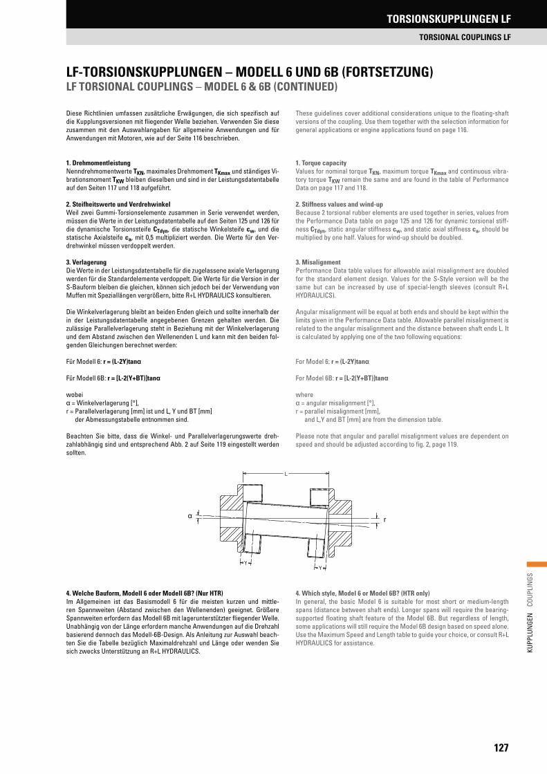
127
KUPP
LUN
GEN
C
OUPL
INGS
LF-TORSIONSKUPPLUNGEN – MODELL 6 UND 6B (FORTSETZUNG) LF TORSIONAL COUPLINGS – MODEL 6 & 6B (CONTINUED)
Diese Richtlinien umfassen zusätzliche Erwägungen, die sich spezifisch auf die Kupplungsversionen mit fliegender Welle beziehen. Verwenden Sie diese zusammen mit den Auswahlangaben für allgemeine Anwendungen und für Anwendungen mit Motoren, wie auf der Seite 116 beschrieben.
1. DrehmomentleistungNenndrehmomentwerte TKN, maximales Drehmoment TKmax und ständiges Vi-brationsmoment TKW bleiben dieselben und sind in der Leistungsdatentabelle auf den Seiten 117 und 118 aufgeführt.
2. Steifheitswerte und VerdrehwinkelWeil zwei Gummi-Torsionselemente zusammen in Serie verwendet werden, müssen die Werte in der Leistungsdatentabelle auf den Seiten 125 und 126 für die dynamische Torsionssteife CTdyn, die statische Winkelsteife cw, und die statische Axialsteife ca, mit 0,5 multipliziert werden. Die Werte für den Ver-drehwinkel müssen verdoppelt werden.
3. VerlagerungDie Werte in der Leistungsdatentabelle für die zugelassene axiale Verlagerung werden für die Standardelemente verdoppelt. Die Werte für die Version in der S-Bauform bleiben die gleichen, können sich jedoch bei der Verwendung von Muffen mit Speziallängen vergrößern, bitte R+L HYDRAULICS konsultieren.
Die Winkelverlagerung bleibt an beiden Enden gleich und sollte innerhalb der in der Leistungsdatentabelle angegebenen Grenzen gehalten werden. Die zulässige Parallelverlagerung steht in Beziehung mit der Winkelverlagerung und dem Abstand zwischen den Wellenenden L und kann mit den beiden fol-genden Gleichungen berechnet werden:
Für Modell 6: r = (L-2Y)tan
Für Modell 6B: r = [L-2(Y+BT)]tan
wobei = Winkelverlagerung [°],
r = Parallelverlagerung [mm] ist und L, Y und BT [mm] der Abmessungstabelle entnommen sind.
Beachten Sie bitte, dass die Winkel- und Parallelverlagerungswerte dreh-zahlabhängig sind und entsprechend Abb. 2 auf Seite 119 eingestellt werden sollten.
4. Welche Bauform, Modell 6 oder Modell 6B? (Nur HTR)Im Allgemeinen ist das Basismodell 6 für die meisten kurzen und mittle-ren Spannweiten (Abstand zwischen den Wellenenden) geeignet. Größere Spannweiten erfordern das Modell 6B mit lagerunterstützter fliegender Welle. Unabhängig von der Länge erfordern manche Anwendungen auf die Drehzahl basierend dennoch das Modell-6B-Design. Als Anleitung zur Auswahl beach-ten Sie die Tabelle bezüglich Maximaldrehzahl und Länge oder wenden Sie sich zwecks Unterstützung an R+L HYDRAULICS.
These guidelines cover additional considerations unique to the floating-shaft versions of the coupling. Use them together with the selection information for general applications or engine applications found on page 116.
1. Torque capacityValues for nominal torque TKN, maximum torque TKmax and continuous vibra-tory torque TKW remain the same and are found in the table of Performance Data on page 117 and 118.
2. Stiffness values and wind-upBecause 2 torsional rubber elements are used together in series, values from the Performance Data table on page 125 and 126 for dynamic torsional stiff-ness CTdyn, static angular stiffness cw, and static axial stiffness ca, should be multiplied by one half. Values for wind-up should be doubled.
3. MisalignmentPerformance Data table values for allowable axial misalignment are doubled for the standard element design. Values for the S-Style version will be the same but can be increased by use of special-length sleeves (consult R+L HYDRAULICS).
Angular misalignment will be equal at both ends and should be kept within the limits given in the Performance Data table. Allowable parallel misalignment is related to the angular misalignment and the distance between shaft ends L. It is calculated by applying one of the two following equations:
For Model 6: r = (L-2Y)tan
For Model 6B: r = [L-2(Y+BT)]tan
where = angular misalignment [°],
r = parallel misalignment [mm], and L,Y and BT [mm] are from the dimension table.
Please note that angular and parallel misalignment values are dependent on speed and should be adjusted according to fig. 2, page 119.
4. Which style, Model 6 or Model 6B? (HTR only)In general, the basic Model 6 is suitable for most short or medium-length spans (distance between shaft ends). Longer spans will require the bearing-supported floating shaft feature of the Model 6B. But regardless of length, some applications will still require the Model 6B design based on speed alone. Use the Maximum Speed and Length table to guide your choice, or consult R+L HYDRAULICS for assistance.
r
TORSIONSKUPPLUNGEN LF
TORSIONAL COUPLINGS LF
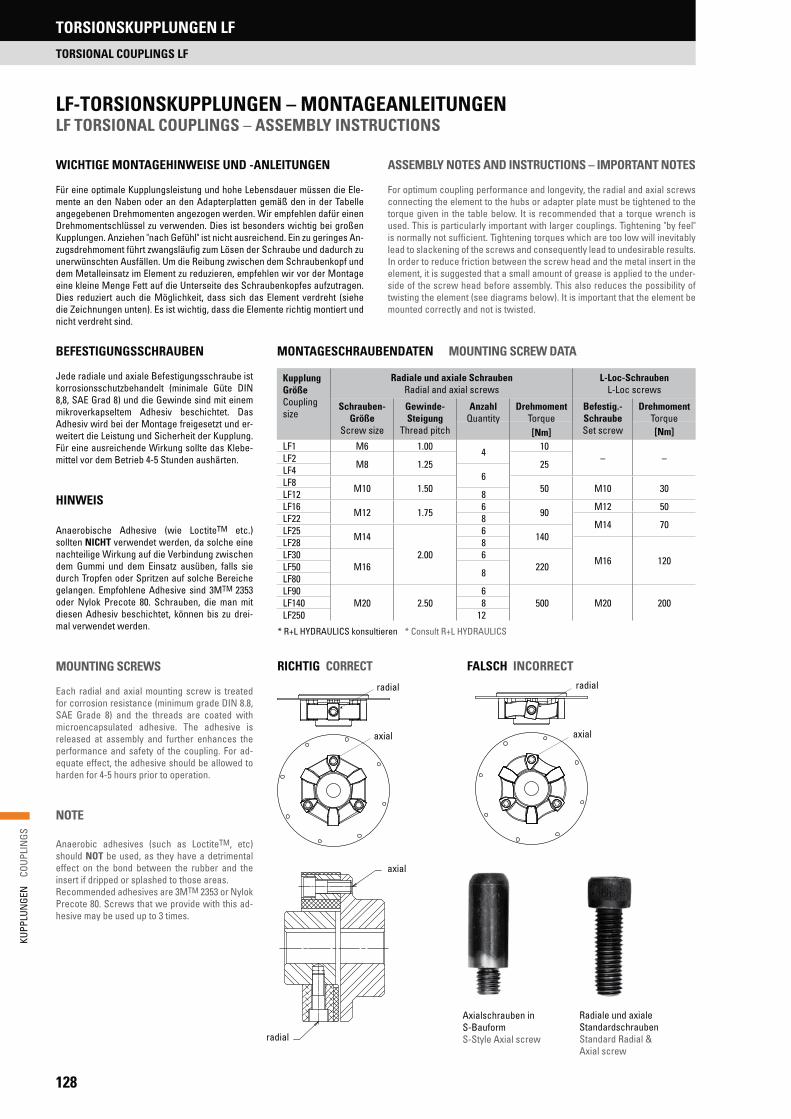
128
KUPP
LUN
GEN
C
OUPL
INGS
LF-TORSIONSKUPPLUNGEN – MONTAGEANLEITUNGEN LF TORSIONAL COUPLINGS – ASSEMBLY INSTRUCTIONS
WICHTIGE MONTAGEHINWEISE UND -ANLEITUNGEN
Für eine optimale Kupplungsleistung und hohe Lebensdauer müssen die Ele-mente an den Naben oder an den Adapterplatten gemäß den in der Tabelle angegebenen Drehmomenten angezogen werden. Wir empfehlen dafür einen Drehmomentschlüssel zu verwenden. Dies ist besonders wichtig bei großen Kupplungen. Anziehen "nach Gefühl" ist nicht ausreichend. Ein zu geringes An-zugsdrehmoment führt zwangsläufig zum Lösen der Schraube und dadurch zu unerwünschten Ausfällen. Um die Reibung zwischen dem Schraubenkopf und dem Metalleinsatz im Element zu reduzieren, empfehlen wir vor der Montage eine kleine Menge Fett auf die Unterseite des Schraubenkopfes aufzutragen. Dies reduziert auch die Möglichkeit, dass sich das Element verdreht (siehe die Zeichnungen unten). Es ist wichtig, dass die Elemente richtig montiert und nicht verdreht sind.
ASSEMBLY NOTES AND INSTRUCTIONS – IMPORTANT NOTES
For optimum coupling performance and longevity, the radial and axial screws connecting the element to the hubs or adapter plate must be tightened to the torque given in the table below. It is recommended that a torque wrench is used. This is particularly important with larger couplings. Tightening "by feel" is normally not sufficient. Tightening torques which are too low will inevitably lead to slackening of the screws and consequently lead to undesirable results. In order to reduce friction between the screw head and the metal insert in the element, it is suggested that a small amount of grease is applied to the under-side of the screw head before assembly. This also reduces the possibility of twisting the element (see diagrams below). It is important that the element be mounted correctly and not is twisted.
BEFESTIGUNGSSCHRAUBEN
Jede radiale und axiale Befestigungsschraube ist korrosionsschutzbehandelt (minimale Güte DIN 8,8, SAE Grad 8) und die Gewinde sind mit einem mikroverkapseltem Adhesiv beschichtet. Das Adhesiv wird bei der Montage freigesetzt und er-weitert die Leistung und Sicherheit der Kupplung. Für eine ausreichende Wirkung sollte das Klebe-mittel vor dem Betrieb 4-5 Stunden aushärten.
HINWEIS
Anaerobische Adhesive (wie LoctiteTM etc.) sollten NICHT verwendet werden, da solche eine nachteilige Wirkung auf die Verbindung zwischen dem Gummi und dem Einsatz ausüben, falls sie durch Tropfen oder Spritzen auf solche Bereiche gelangen. Empfohlene Adhesive sind 3MTM 2353 oder Nylok Precote 80. Schrauben, die man mit diesen Adhesiv beschichtet, können bis zu drei-mal verwendet werden.
MOUNTING SCREWS
Each radial and axial mounting screw is treated for corrosion resistance (minimum grade DIN 8.8, SAE Grade 8) and the threads are coated with microencapsulated adhesive. The adhesive is released at assembly and further enhances the performance and safety of the coupling. For ad-equate effect, the adhesive should be allowed to harden for 4-5 hours prior to operation.
NOTE
Anaerobic adhesives (such as LoctiteTM, etc) should NOT be used, as they have a detrimental effect on the bond between the rubber and the insert if dripped or splashed to those areas.Recommended adhesives are 3MTM 2353 or Nylok Precote 80. Screws that we provide with this ad-hesive may be used up to 3 times.
MONTAGESCHRAUBENDATEN MOUNTING SCREW DATA
RICHTIG CORRECT
radial
axial
FALSCH INCORRECTradial
axial
radial
axial
* R+L HYDRAULICS konsultieren * Consult R+L HYDRAULICS
Axialschrauben in S-BauformS-Style Axial screw
Radiale und axiale StandardschraubenStandard Radial & Axial screw
Kupplung GrößeCoupling size
Radiale und axiale Schrauben Radial and axial screws
L-Loc-SchraubenL-Loc screws
Schrauben-Größe
Screw size
Gewinde-Steigung
Thread pitch
AnzahlQuantity
DrehmomentTorque
Befestig.-SchraubeSet screw
DrehmomentTorque
[Nm] [Nm]LF1 M6 1.00 4 10
– –LF2 M8 1.25 25LF4 6LF8 M10 1.50 50 M10 30LF12 8LF16 M12 1.75 6 90 M12 50LF22 8 M14 70LF25 M14
2.00
6 140LF28 8
M16 120LF30M16
6220LF50 8LF80
LF90M20 2.50
6500 M20 200LF140 8
LF250 12
TORSIONSKUPPLUNGEN LF
TORSIONAL COUPLINGS LF
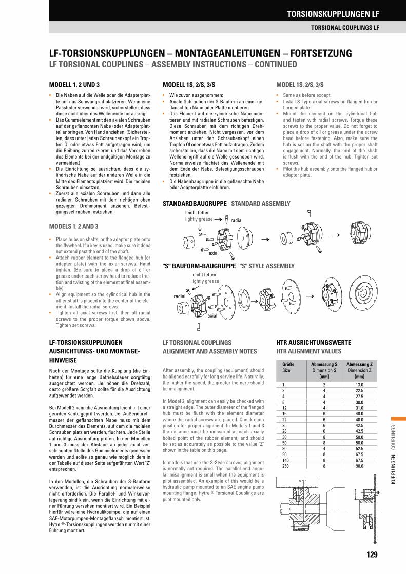
129
KUPP
LUN
GEN
C
OUPL
INGS
LF-TORSIONSKUPPLUNGEN – MONTAGEANLEITUNGEN – FORTSETZUNG LF TORSIONAL COUPLINGS – ASSEMBLY INSTRUCTIONS – CONTINUED
MODELL 1, 2 UND 3
• Die Naben auf die Welle oder die Adapterplat-te auf das Schwungrad platzieren. Wenn eine Passfeder verwendet wird, sicherstellen, dass diese nicht über das Wellenende herausragt.
• Das Gummielement mit den axialen Schrauben auf der geflanschten Nabe (oder Adapterplat-te) anbringen. Von Hand anziehen. (Sicherstel-len, dass unter jeden Schraubenkopf ein Trop-fen Öl oder etwas Fett aufgetragen wird, um die Reibung zu reduzieren und das Verdrehen des Elements bei der endgültigen Montage zu vermeiden.)
• Die Einrichtung so ausrichten, dass die zy-lindrische Nabe auf der anderen Welle in die Mitte des Elements platziert wird. Die radialen Schrauben einsetzen.
• Zuerst alle axialen Schrauben und dann alle radialen Schrauben mit dem richtigen oben gezeigten Drehmoment anziehen. Befesti-gungsschrauben festziehen.
MODELS 1, 2 AND 3
• Place hubs on shafts, or the adapter plate onto the flywheel. If a key is used, make sure it does not extend past the end of the shaft.
• Attach rubber element to the flanged hub (or adapter plate) with the axial screws. Hand tighten. (Be sure to place a drop of oil or grease under each screw head to reduce fric-tion and twisting of the element at final assem-bly).
• Align equipment so the cylindrical hub in the other shaft is placed into the center of the ele-ment. Install the radial screws.
• Tighten all axial screws first, then all radial screws to the proper torque shown above. Tighten set screws.
MODELL 1S, 2/S, 3/S
• Wie zuvor, ausgenommen:• Axiale Schrauben der S-Bauform an einer ge-
flanschten Nabe oder Platte montieren. • Das Element auf die zylindrische Nabe mon-
tieren und mit radialen Schrauben befestigen. Diese Schrauben mit dem richtigen Dreh-moment anziehen. Nicht vergessen, vor dem Anziehen unter den Schraubenkopf einen Tropfen Öl oder etwas Fett aufzutragen. Zudem sicherstellen, dass die Nabe mit dem richtigen Welleneingriff auf die Welle geschoben wird. Normalerweise fluchtet das Wellenende mit dem Ende der Nabe. Befestigungsschrauben festziehen.
• Die Nabenbaugruppe in die geflanschte Nabe oder Adapterplatte einführen.
LF-TORSIONSKUPPLUNGEN AUSRICHTUNGS- UND MONTAGE-HINWEISE
Nach der Montage sollte die Kupplung (die Ein-heiten) für eine lange Betriebsdauer sorgfältig ausgerichtet werden. Je höher die Drehzahl, desto größere Sorgfalt sollte für die Ausrichtung aufgewendet werden.
Bei Modell 2 kann die Ausrichtung leicht mit einer geraden Kante geprüft werden. Der Außendurch-messer der geflanschten Nabe muss mit dem Durchmesser des Elements, auf dem die radialen Schrauben platziert werden, fluchten. Jede Stelle auf richtige Ausrichtung prüfen. In den Modellen 1 und 3 muss der Abstand an jeder axial ver-schraubten Stelle des Gummielements gemessen werden und sollte so genau wie möglich dem in der Tabelle auf dieser Seite aufgeführten Wert "Z" entsprechen.
In den Modellen, die Schrauben der S-Bauform verwenden, ist die Ausrichtung normalerweise nicht erforderlich. Die Parallel- und Winkelver-lagerung sind klein, wenn die Einrichtung mit ei-ner Führung versehen montiert wird. Ein Beispiel hierfür wäre eine Hydraulikpumpe, die auf einen SAE-Motorpumpen-Montageflansch montiert ist. Hytrel®-Torsionskupplungen werden nur mit einer Führung montiert.
LF TORSIONAL COUPLINGS ALIGNMENT AND ASSEMBLY NOTES
After assembly, the coupling (equipment) should be aligned carefully for long service life. Naturally, the higher the speed, the greater the care should be in alignment.
In Model 2, alignment can easily be checked with a straight edge. The outer diameter of the flanged hub must be flush with the element diameter where the radial screws are placed. Check each position for proper alignment. In Models 1 and 3 the distance must be measured at each axially bolted point of the rubber element, and should be set as accurately as possible to the value "Z" shown in the table on this page.
In models that use the S-Style screws, alignment is normally not required. The parallel and angu-lar misalignment is small when the equipment is pilot assembled. An example of this would be a hydraulic pump mounted to an SAE engine pump mounting flange. Hytrel® Torsional Couplings are pilot mounted only.
Größe Size
Abmessung SDimension S
[mm]
Abmessung ZDimension Z
[mm]
1 2 13.02 4 22.54 4 27.58 4 30.012 4 31.016 6 40.022 6 40.025 6 42.528 6 42.530 8 50.050 8 50.080 4 52.590 8 67.5140 8 67.5250 8 90.0
HTR AUSRICHTUNGSWERTE HTR ALIGNMENT VALUES
MODEL 1S, 2/S, 3/S
• Same as before except:• Install S-Type axial screws on flanged hub or
flanged plate.• Mount the element on the cylindrical hub
and fasten with radial screws. Torque these screws to the proper value. Do not forget to place a drop of oil or grease under the screw head before fastening. Also, make sure the hub is set on the shaft with the proper shaft engagement. Normally, the end of the shaft is flush with the end of the hub. Tighten set screws.
• Pilot the hub assembly onto the flanged hub or adapter plate.
STANDARDBAUGRUPPE STANDARD ASSEMBLYleicht fettenlightly grease radial
axial
leicht fettenlightly grease
radial
axial
"S" BAUFORM-BAUGRUPPE "S" STYLE ASSEMBLY
TORSIONSKUPPLUNGEN LF
TORSIONAL COUPLINGS LF
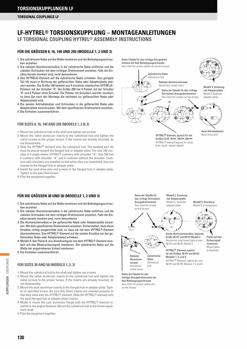
130
KUPP
LUN
GEN
C
OUPL
INGS
LF-HYTREL® TORSIONSKUPPLUNG – MONTAGEANLEITUNGEN LF TORSIONAL COUPLING HYTREL® ASSEMBLY INSTRUCTIONS
FÜR DIE GRÖSSEN 8, 16, 140 UND 250 (MODELLE 1, 2 UND 3)
1. Die zylindrische Nabe auf die Welle montieren und die Befestigungsschrau-ben anziehen.
2. Die radialen Aluminiumeinsätze in die zylindrische Nabe einführen und die radialen Schrauben mit dem richtigen Drehmoment anziehen. Falls die Ein-sätze bereits montiert sind, nicht demontieren.
3. Das HYTREL®-Element auf die zylindrische Nabe schieben. Das gerippte Teil (A) muss in Richtung der geflanschten Nabe oder Adapterplatte plat-ziert werden. Die Größe 140 besteht aus 4 einzelnen elastischen HYTREL®-Polstern mit der Schulter "A". Die Größe 250 hat 4 Polster mit der Schulter "A" und 4 Polster ohne Schulter. Die Polster mit Schultern werden montiert, so dass Sie nach der Montage die nächsten zur geflanschten Nabe oder Adapterplatte sind.
4. Die axialen Antriebsbolzen und Schrauben in die geflanschte Nabe oder Adapterplatte einschrauben. Mit dem spezifizierten Drehmoment anziehen.
5. Die Einheiten zusammenführen.
FOR SIZES 8, 16, 140 AND 250 (MODELS 1, 2 & 3)
1. Mount the cylindrical hub to the shaft and tighten set screws.2. Mount the radial aluminium inserts to the cylindrical hub and tighten the
radial screws to the proper torque. If the inserts are already mounted, do not disassemble.
3. Slide the HYTREL® element onto the cylindrical hub. The webbed part (A) must be placed toward the flanged hub or adapter plate. The size 140 con-sists of 4 single elastic HYTREL® cushions with shoulder “A”. Size 250 has 4 cushions with shoulder “A” and 4 cushions without the shoulder. Cush-ions with shoulders are installed so that when they are assembled, they are nearest to the flanged hub or adapter plate.
4. Install the axial drive pins and screws to the flanged hub or adapter plate. Tighten to the specified torque.
5. Pilot the equipment together.
FÜR DIE GRÖSSEN 30 UND 50 (MODELLE 1, 2 UND 3)
1. Die zylindrische Nabe auf die Welle montieren und die Befestigungsschrau-ben anziehen.
2. Die radialen Aluminiumeinsätze in die zylindrische Nabe einführen und die radialen Schrauben mit dem richtigen Drehmoment anziehen. Falls die Ein-sätze bereits montiert sind, nicht demontieren.
3. Die Aluminiumeinsätze in die geflanschte Nabe oder Adapterplatte einset-zen. Mit dem spezifizierten Drehmoment anziehen. Sicherstellen, dass diese Einsätze richtig ausgerichtet sind, so dass sie mit dem HYTREL®-Element übereinstimmen. Das HYTREL®-Element auf die axialen Einsätze (an der ge-flanschten Nabe oder Adapterplatte) schieben.
4. Modell 4: den Flansch aus Aluminiumguss mit dem HYTREL®-Element mon-tiert auf das Motorschwungrad montieren. Die zylindrische Nabe auf die Welle der angetriebenen Einheit montieren.
5. Die Einheiten zusammenführen.
FOR SIZES 30 AND 50 (MODELS 1, 2, 3)
1. Mount the cylindrical hub to the shaft and tighten set screws.2. Mount the radial aluminium inserts to the cylindrical hub and tighten the
radial screws to the proper torque. If the inserts are already mounted, do not disassemble.
3. Mount the axial aluminium inserts to the flanged hub or adapter plate. Tight-en to specified torque. Be sure that these inserts are oriented properly so that they mate with the HYTREL® element. Slide the HYTREL® element onto the axial (flanged hub or adapter plate) inserts.
4. Model 4: mount the cast aluminium flange with the HYTREL® element in-stalled to the engine flywheel. Mount the cylindrical hub to the driven equip-ment shaft.
5. Pilot the equipment together.
Siehe die Tabelle für das richtige Schrauben- AnzugsdrehmomentSee chart for proper screw torque
Modell 3, Schwung-rad-Adapterplatte Model 3, flywheel adapter plate
Modell 3, AnordungModel 3, arrangement
Platte auf das Schwungrad montierenMount plate to flywheelHYTREL®-Element, typisch
für die Größen 30 HY und 50 HY, Modelle 1, 2, und 3 HYTREL®-Element, typical for size 30 HY and 50 HY, Models 1, 2 and 3
Radialer Aluminium-einsatzAluminium radial insert
Zylindrische NabeCylindrical hub
Siehe die Tabelle für das richtige Anzugsdrehmoment der Keil-BefestigungsschraubeSee chart for proper spline set screw torque
Axiale Aluminiumeinsätze, typische Größe 30 HY und 50 HY Modell 3Aluminium axial insert typical size 30 HY and 50 HY, Model 3
Siehe Tabelle für das richtige Anzugsdreh- moment der Keil-BefestigungsschraubeSee chart for proper spline set screw torque
Zylindrische NabeCylindrical hub
Radialer AluminiumeinsatzAluminium radial insert
Siehe die Tabelle für das richtige Schrauben-AnzugsdrehmomentSee chart for proper screw torque
"A"
Modell 3, Schwung-rad-AdapterplatteModel 3 flywheel adapter plate
Axial AntriebsbolzenAxial drive pinsHYTREL®-Element, typisch für die
Größen 8 HY, 16 HY, 140 HY, 250 HYHYTREL® element typical for sizes 8 HY, 16 HY, 140 HY, 250 HY
TORSIONSKUPPLUNGEN LF
TORSIONAL COUPLINGS LF

131
KUPP
LUN
GEN
C
OUPL
INGS
Die LK-Torsionskupplung ist eine einfache, stabile, zweiteilige Kupplung, die aus einem Element oder einem Schwungradadapter zusammen mit einer Nabe mit Keilnut besteht. Sie wird bei Anwendungen mit einem Diesel-, Ben-zin- oder Erdgas-Motor verwendet, der eine oder mehrere flanschmontierte Hydraulikpumpen antreibt. Die Kupplungen sind sehr torsionssteif (nahezu starr) und ermöglichen Hydraulikpumpen und ähnlichen Einheiten, die eine geringe Masse oder Trägheit aufweisen, unter der kritischen Drehzahl zu betreiben. Die sehr steife LK-Kupplung verschiebt die kritische Drehzahl weit über den Betriebsbereich hinaus und liefert einen Antrieb ohne schädliche Torsionsvibrationen. Die LK-Kupplung ist die ideale Wahl für hydrostatische Antriebe, hauptsächlich für den unteren und mittleren Leistungsbereich. Ty-pische Anwendungen sind Bagger, Vibrationswalzen, Lader, Kräne, Personen-aufzüge, Gabelstapler, Traktoren etc. Die LK-Kupplung kann praktisch für alle motorgetriebenen hydrostatischen Anwendungen im niedrigen bis mittleren Leistungsbereich eingesetzt werden.
The LK Torsional Coupling is a simple, robust, two-piece coupling consisting of an element or flywheel adapter flange together with a splined hub. It is used on applications that have a diesel, gasoline or natural gas engine driving one or more flange mounted hydraulic pumps. The couplings are torsionally very stiff (almost rigid) enabling drives of hydraulic pumps and similar equipment having low mass or inertia to operate below the critical speed. The very stiff LK raises the critical speed well above the operating range providing a drive free of any harmful torsional vibrations. The LK is an ideal choice for hydrostatic construction drives, mainly in the low to mid power ranges. Typical applica-tions are excavators, vibratory rollers, loaders, cranes, elevators, forklifts, tractors, etc. Virtually all engine driven hydrostatic applications in the low to mid power range can use the LK coupling.
TORSIONSKUPPLUNGEN LKTORSIONAL COUPLINGS LK
TORSIONSKUPPLUNGEN LK
TORSIONAL COUPLINGS LK

132
KUPP
LUN
GEN
C
OUPL
INGS
TORSIONSKUPPLUNGEN LK TORSIONAL COUPLINGS LK
HERVORRAGENDE EIGENSCHAFTEN UND VORTEILE
• Kompakt, niedriges Gewicht, robust und betriebssicher mit einer langen Betriebsdauer.
• Ölbeständig und passend für Temperaturen von -40 °C bis zu +150 °C.• Eine hohe Torsionssteife erlaubt den Betrieb unter der kritischen Drehzahl
ohne Resonanzen, vorausgesetzt die Kupplung wurde richtig ausgewählt.• Wartungsfreie Kombination aus Sintermetall mit temperaturstabilisiertem
Spezial-Polyamid hoher Stoßfestigkeit.• Kurze Einbaulänge, einfache Montage, da die Kupplung axial montiert wer-
den kann.• Die Naben können mit dem bewährten patentierten L-Loc-Klemmsystem
ausgestattet werden. Mit L-Loc kann die Kupplungsnabe absolut bewe-gungsfrei auf Keilwellen angepasst werden, um den Reibungsverschleiß zu vermeiden.
• Die Naben können wie erforderlich in Form und Länge modifiziert werden.• Verschiedene Serien für genormte SAE-Schwungräder und ungenormte
Schwungräder.
KONSTRUKTION UND MATERIALIEN
Modernes Design, das ein rationales und ökonomisches Erzeugnis ergibt – gute Materialeigenschaften – ein seit Jahren bewährtes Konstruktionsprinzip.
NABEN
Hohe Qualität durch die Verwendung präziser Sintermetallnaben für alle LK-Kupplungsgrößen. Diese Naben werden bei Lovejoy gründlich getestet und haben sich bei vielen Anwendungen bewährt. Die einteiligen Naben (oder Nabensterne) haben Mitnehmer, die den Eingriff in das Element liefern. Die Seiten der Mitnehmer sind leicht ballig, um einen Kantendruck bei Winkelver-lagerungen zu vermeiden.
SCHWUNGRADFLANSCHE
Diese Flansche bestehen aus einem hochqualitativen Kunststoffspritzguss, der mit Glasfaser verstärkt ist, um ein hitzestabiles Produkt zu erhalten, dass eine hohe Belastungsstärke zeigt. Grundsätzlich ist der Schwungradflansch oder das Element in zwei unterschiedlichen Konstruktionen erhältlich:
A) Einteilig mit Einbaumaßen sowohl SAE J620 entsprechend als auch in ver-schiedenen metrischen Größen.
B) Zweiteilig mit einem universellen Kunststoffflansch, der mit einem Stahlad-apter an jedem Schwungrad befestigt werden kann. Solche Stahladapter können vom Kunden entweder selbst gefertigt oder von R+L HYDRAULICS geliefert werden.
Die einteiligen Flansche können in zwei unterschiedliche Positionen auf das Schwungrad montiert werden, wodurch sich zwei axiale Einbaulängen erge-ben. Die zweiteiligen Flansche können in vier unterschiedlichen Positionen montiert werden, woraus sich vier unterschiedliche Einbaulängen ergeben. Mit den unterschiedlichen Flanschpositionen und unterschiedlichen Längen der Naben kann die ideale Gesamtlänge der Kupplung erreicht werden.
SALIENT FEATURES AND ADVANTAGES
• Compact, light, robust and safe in operation with long service life.• Oil resistant and suitable for temperatures of -40 °C up to +150 °C.• High torsional stiffness-allowing operation below critical speed without
resonances, provided it is correctly selected.• Service free combination of sintered metal with highly shock resistant,
temperature stabilized special polyamide.• Short mounting length, easy assembly since it can be mounted axially.• The hubs can be equipped with the proven patented L-Loc clamping sys-
tem. With L-Loc, the coupling hub can be fit to splined shafts absolutely free of movement to eliminate fretting.
• The hubs can be modified in form and length as needed.• Various series for standardized SAE-flywheels and non-standard flywheels.
DESIGN AND MATERIALS
Modern construction to give rational and economic manufacture-good mate-rial properties-design principle proven over the years.
HUBS
High-quality, precision powdered-metal hubs are used for all sizes of the LK. These hubs are thoroughly tested by Lovejoy and proven in many applications. These one-piece hubs (or hubstars) have “dogs” that provide the engagement with the element. The sides of the dogs are lightly crowned to avoid edge pres-sure at angular misalignments.
FLYWHEEL FLANGES
These flanges are molded in high quality plastic, strengthened with glass fiber to produce a heat-stabilized product displaying high impact strength. Funda-mentally the flywheel flange or element is available in two different designs:
A) One-Piece with mounting measurements to SAE J620 as well as to various metric sizes.
B) Two-Piece consisting of one universal plastic flange, which can be fitted with steel adapter to any flywheel. Such steel adapters can be produced either by the customer himself or delivered by R+L HYDRAULICS.
The one-piece flanges can be mounted to the flywheel in two different posi-tions, resulting in two different axial mounting lengths. The two-piece flanges with adapter can be arranged in four different positions, resulting in four dif-ferent axial mounting lengths. By using the different positions of the flanges and different lengths of the hubs, the ideal overall length for the coupling can be reached.
TORSIONSKUPPLUNGEN LK
TORSIONAL COUPLINGS LK

133
KUPP
LUN
GEN
C
OUPL
INGS
TORSIONSKUPPLUNGEN LKTORSIONAL COUPLINGS LK
LK-KUPPLUNGEN-LEISTUNGSDATEN LK PERFORMANCE DATA
VERLAGERUNGDa die Kupplung sehr torsionssteif ist, ist sie auch in radialer Richtung sehr steif und deshalb für genau ausgerichtete Antriebe (flanschmontiert) geeig-net. Die Kupplung kann kleine Radial- und Winkelverlagerungen ausgleichen, wie sie normalerweise an flanschmontierten Antrieben erwartet werden. In der Axialrichtung kann die Nabe sich frei bewegen und kann einige Millimeter von der idealen axialen Position selbst über den Flansch hinausragend mon-tiert werden. Bei hochbelasteten Kupplungen wird jedoch empfohlen, dass die Mitnehmer jederzeit vollständig im Eingriff sind.
MONTAGEIn den meisten Fällen ist der Durchmesser des Nabensterns kleiner als der zentrale Aufnahmedurchmesser des Pumpenflansches (der Nabenstern passt durch die Bohrung im Flansch, der die Pumpe mit dem Schwungradgehäuse verbindet). Der Durchmesser des Nabensterns ist immer etwas kleiner als die normale Größe der Kupplung (der Rotationsdurchmesser des Nabensterns für die LF-K-100 ist < 100 mm und passt durch die Bohrung in der Pumpen-Mon-tageplatte, vorausgesetzt, dass diese einen Durchmesser von 100 mm oder darüber hat). In diesem Fall kann die Montage wie folgt erfolgen: (Siehe die Abbildung unten links)1. Den Kupplungsflansch an das Schwungrad schrauben.2. Die Pumpenmontageplatte auf das Schwungradgehäuse schrauben.3. Die Kupplung auf die Pumpenwelle schieben und sichern.4. Zum Eingriff der Kupplung mit der Pumpe, die Pumpe durch die Pumpen-
montageplatte beischieben.
In einigen Fällen, bei denen der Nabenstern-Durchmesser größer als die Boh-rung in der Pumpenmontageplatte ist, sollte die Montage wie folgt durchge-führt werden: (Siehe die Abbildung unten in der Mitte)
1. Den Kupplungsflansch an das Schwungrad schrauben.2. Die Pumpenmontageplatte an der Pumpe festschrauben.3. Die Kupplungsnabe auf die Pumpenwelle schieben und sichern.4. Die Pumpe mit der Montageplatte beischieben, bis die Kupplung eingreift
und dann die Montageplatte im Schwungradgehäuse fixieren. Die kom-plette Baugruppe am Schwungradgehäuse festschrauben.
AXIALE SICHERUNG DER NABEDie Nabe kann sich in ihrer axialen Position frei einstellen, da kein axialer Anschlag vorhanden ist. Daher muss die Nabe auf der Pumpenwelle axial gesichert werden. Für beste Ergebnisse verwenden Sie unser bewährtes L-Loc-Klemmsystem. Für leichte Antriebe, bei denen die Pumpenwelle mit einem Absatz versehen ist, kann es vorteilhaft sein, die Nabe mit einer Schraube und Scheibe am Wellenende festzuschrauben, vorausgesetzt, die Welle ist mit einer Gewindebohrung ausgestattet.
MISALIGNMENTAs the coupling is torsionally very stiff, it is also very stiff in the radial direc-tion. It is suitable for accurately aligned drives (flange mounted). The coupling is able to compensate for the small radial and angular misalignments that must normally be expected on flange mounted drives. In the axial direction, the hub can move freely and be located a few millimeters from the ideal axial position, even to the point of protruding out of the flange. However, for highly loaded couplings, it is recommended that the dogs are completely engaged at all times.
MOUNTINGIn most cases, the diameter of the hubstar is smaller than the center locating diameter of the pump flange (the hubstar passes through bore in the flange which connects the pump with the flywheel housing). The diameter of the hub-star is always a little smaller than the normal size of the coupling (the rotation diameter of the hubstar for LF-K-100 is < 100 mm; it will pass through the bore in the pump mounting plate provided it is 100 mm in diameter or greater). In this case the installation can be carried out as follows: (See bottom left picture)1. Bolt the coupling flange onto the flywheel.2. Bolt the pump mounting plate onto the flywheel housing.3. Fit coupling onto the pump shaft and secure.4. Offer up pump to engage coupling and pump in the pump mounting plate.
For the occasional case where the hubstar diameter is larger than the bore in the pump mounting plate, the installation should be carried out as follows: (See bottom center picture)
1. Bolt the coupling flange onto the flywheel.2. Bolt pump mounting plate to pump.3. Fit coupling hub onto the pump shaft and secure.4. Offer up pump and mounting plate so coupling engages and locate the pump
mount plate in the flywheel housing. Bolt complete assembly to flywheel housing.
AXIAL SECURING OF HUBThe hub can adjust its axial position freely as there is no axial stop. Therefore, the hub has to be secured onto the pump shaft axially. For best results use our proven L-Loc clamping system. For light drives where the pump shaft has a shoulder it can be sufficient to clamp the hub against the shoulder using a bolt and washer fastened onto the end of the pump shaft, provided it has a tapped hole.
Kupplung GrößeCoupling size
Nenn- Drehmoment
Nominal torque
TKN[Nm]
Max.DrehmomentMax. torque
TKmax[Nm]
Max.Drehzahl
Max. speed
n[1/min]
Dynamische Torsionssteife Dynamic torsional stiffness
CTdyn [kNm/rad]
RelativeDämpfung
Relative damping
[–]0.25 TKN 0.50 TKN 0.75 TKN 1.00 TKNLK80 125 330 6000 44 50 72 96LK100 400 800 5000 55 62 90 120LK125 800 1600 4500 155 180 315 460 0.4LK150 1200 3000 4000 260 280 420 900LK150D 2400 6000 4000 520 560 840 1800
TORSIONSKUPPLUNGEN LK
TORSIONAL COUPLINGS LK

134
KUPP
LUN
GEN
C
OUPL
INGS
ABMESSUNGEN FÜR SAE J620 SCHWUNGRAD-ANWENDUNGENDIMENSIONS FOR SAE J620 FLYWHEEL APPLICATIONS
* Andere kürzere oder längere Nabenlängen sind für spezielle Anforderungen erhältlich.** LK150D benutzt 2 ZYTEL®-Elemente parallel mit 1 Stahlplatte.
ABMESSUNGEN FÜR UNIVERSAL-ELEMENTE (FÜR NICHT-SAE-SCHWUNGRÄDER ETC.)DIMENSIONS FOR UNIVERSAL ELEMENTS (FOR NON-SAE FLYWHEELS, ETC.)
*Größe LK80-6-135, Führungen am Außendurchmesser. *Size LK80-6-135 pilots on the O.D.
SAE PUMPENKEILWELLEN*SAE PUMP SPLINES*
* SAE J744
G
H
* Other shorter or longer hub lengths available for special requirements.** LK150D uses 2 ZYTEL® elements in parallel with 1 steel plate.
SAECode
Anzahl der ZähneNumber of teeth
Keil-AbstandSpline pitch
Größter DurchmesserMajor diameter
[mm]A-A
920/40 12.7
A16/32
15.9B 13 22.2B-B 15 25.4C 14
12/2431.8
C-C 17 38.1D
138/16
44.5EF 15 50.8
Kupplung GrößeCoupling size
Nenn-Drehmoment
Nominal torque
Bohrungs-durchmesser
Bore diameter
SAESchwungradSAE flywheel
FlanschmaßeFlange dimensions
Nabenstern Hubstar
Baugruppe Assembly
Flansch BauformFlange style OD
[mm]BC
[mm]
Anzahl und Durch -messer der BohrungNumber & diameter
of holes
Flansch StärkeFlange
thickness[mm]
OB[mm]
LTB*[mm]
OAL[mm]
MontagelängeMounting length
Min [mm]
Max[mm]
GrößeSize[mm][Nm]
Länge[mm]
LK100 400 15 40
6.5
1-teilig/1-piece
215.9 200.0 6 x 8.5
14.0 6532 34 23+/-37.5 241.3 222.3 8 x 8.5
8.0 263.5 244.5 8 x 10.5 56 58 58+/-310.0 314.3 295.3 48 50 50+/-3
LK125 800 20 55 10.0 1-teilig/1-piece 314.3 295.3 8 x 10.5 20.0 85 48 50 50+/-311.5 352.4 333.4 42 46 36+/-3
LK150 1200 25 70 11.5 1-teilig/1-piece 352.4 333.4 8 x 10.5 20.0 110 53 53 33+/-114.0 2-teilig/1-piece 466.7 438.2 8 x 12.7 5.0 25+/-1
LK150D 2400 30 70 14.0 ** 466.7 438.2 8 x 12.7 3.4 110 52 54 25+/-1
Element GrößeElement size
Führung Pilot
B.C. Anzahl der BohrungenNumber of holes
Bohr.-DurchmesserHole diameter
A[mm]
B[mm]
S[mm]
C[mm]
D[mm]
E[mm]
F[mm]
G[mm]
H[mm]
LK80-6-106* 106 130 5 8.4 150 91.4 28.4 4.8 14.0 9.7LK80-6-135 135 100
310.4 135 92.2 25.4 * 9.9 15.5
LK100-165 125 142 12.5 174 125.0 34.0 4.010.0
20.0LK100-072 72 165 16.5 200 110.0LK125-195 135 6 12.5 195 135.0 30.0 6.0 14.0LK150-230 165 200 8 230 165.0 27.0 5.0 12.0
1-teiliger Flansch1-Piece flange
2-teiliger Flansch2-Piece flange
Universal-ElementUniversal element
OAL
Anzahl und Durchmesser der BohrungenNumber and diameter of holes
Flansch-stärkeFlange
thickness
OD BC
LTBBohr. DurchmesserBore diameter
Nabensternaußendurchm.Hubstar OB
OAL
Anzahl und Durchmesser
der BohrungenNumber and
diameter of holes
ODBC
LTBBohr. DurchmesserBore diameter
Nabensternaußendurchm.Hubstar OB
S
A D B C
F
E
Anzahl gleichmäßig verteilter BohrungenNumber of equally spaced holes
Montagelänge Mounting length
Montagelänge Mounting length
TORSIONSKUPPLUNGEN LK TORSIONAL COUPLINGS LK
TORSIONSKUPPLUNGEN LK
TORSIONAL COUPLINGS LK

135
KUPP
LUN
GEN
C
OUPL
INGS
TORSIONSKUPPLUNGEN
TORSIONAL COUPLINGS
LOVEJOY-PUMPENMONTAGEPLATTEN LOVEJOY PUMP MOUNTING PLATES
Pumpenmontageplatten von Lovejoy komplettieren Ihre Motoren-, Kupplungs- und Hydraulikpumpeneinheiten. Diese Platten liefern eine einfache Montage von Pumpen an Motoren-Schwungradgehäusen. Pumpenmontageplatten sind in zwei Standardtypen erhältlich: flache oder Abstandstypen. Montageplatten sind verfügbar für alle SAE-Gehäusegrößen 1 bis 6 und alle SAE-Hydraulik-pumpentypen von A bis D. DIN-Hydraulikpumpenführungen und Schrauben-muster sind ebenso erhältlich.
HINWEIS: Die Pumpenmontageplatte wird zur besseren Anschauung auf dem Foto rechts als Schnittmodell gezeigt.
Lovejoy pump mounting plates complete your engine, coupling, and hydraulic pump selection. These plates provide easy mounting of pumps to the engine flywheel housing. Pump mounting plates are available in two standard types: flat and spacer types. Stock plates are available for all SAE housings sizes 1 to 6 and all types of SAE A to D hydraulic pumps. DIN hydraulic pump pilots and bolt patterns also available.
NOTE: Pump mounting plate is cut away in photo to right, for clarity.
SAE J620 ABMESSUNGENSAE J620 DIMENSION REFERENCE
TYPISCHE SCHWUNGRADGEHÄUSEKOMBINATIONTYPICAL FLYWHEEL HOUSING COMBINATIONS
• Bevorzugt Andere Größen erhältlich• Preferred Other sizes available
Gewindebohrungen Tapped holes
P1
BC
P2D
J
H
G
SAE SchwungradgrößeSAE Flywheel size
KupplungsgrößenCoupling sizes
SAE-SchwungradgehäuseSAE flywheel housing
6 5 4 3 2 16 ½ 8, 16, 257 ½ 8, 16, 258 16, 25, 3010 25, 30, 5011 ½ 30, 50, 90, 14014 90, 140, 250
SchwungradgrößeFlywheel size
FührungPilot
P1[mm]
Schrauben-Kreis
Bolt circleBC
[mm]G
[mm]H
[mm]J
[mm]P2
[mm]D
[mm]
GewindelöcherTapped holes
Anz. No. Größe Size
6 ½ 215.90 200.0330.2
12.79.7 184.2 127.0 6
5/16“-187 ½ 241.30 222.25
12.7206.4
–8
8 263.53 244.48 62.0 225.4 63/8“-16
10 314.33 295.28 53.8 15.7 276.2 196.9
811 ½ 352.43 333.38 39.6
28.4 22.4314.3
203.23/8“-16
14 466.73 438.15 25.4 409.61/2“-13
16 517.53 488.9515.7
460.4 190.518 571.50 542.93
31.831.8 498.5 254.0 6
5/8“-1121 673.10 641.35
0.029.2 584.2
– 1224 733.43 692.15 31.8 644.5 3/4“-10

136
KUPP
LUN
GEN
C
OUPL
INGS
TORSIONSKUPPLUNGEN
TORSIONAL COUPLINGS
PBC
M
Ø d
M
Ø d
PBC
13
GF
LF
PBCd
D
EP
13
S
GS
LS
PBCD
EBCOD
d
PUMPEN-MONTAGEPLATTEN FÜR DIE VERWENDUNG AN HYDRAULIKPUMPEN MIT STANDARD-SAE-ANSCHLUSS UND KEILWELLENPUMP MOUNTING PLATES FOR USE WITH HYDRAULIC PUMPS HAVING STANDARD SAE MOUNTINGS AND SPLINE SHAFTS
ABSTANDSRINGE
Abstandsringe sind für alle SAE-Gehäusegrößen (1, 2, 3, 4, 5, 6) erhältlich. Diese Ringe liefern einen zu-sätzlichen Abstand vom Motorenschwungradgehäuse und der Pumpenmontageabstandsplatte. In den meisten Fällen liefert die Standard-Pumpenmontageabstandsplatte den erforderlichen Abstand zwischen dem Schwungrad und der Pumpe für die richtige Torsionskupplung. Bei der Bestellung von Abstands-ringen spezifizieren Sie einfach die SAE-Gehäusegröße und die erforderliche Stärke T.Beispiel: Abstandsring, SAE 3/12,7 (min. Stärke ist 12,7 mm mit stufenweisen Erhöhungen um 3,175 mm).
SPACER RINGS
Spacer rings are available for all SAE bellhousing sizes (1, 2, 3, 4, 5, 6). These rings will provide additional space between the engine flywheel housing and the pump mounting spacer plate. In most cases, the standard pump mounting spacer plate will provide the necessary area between the flywheel and the pump for the proper torsional coupling. When ordering spacer rings, simply specify the SAE bell housing size and required thickness, T. Example: Spacer Ring, SAE 3/12.7 (min. thickness is 12.7 mm, use increments of 3.175 mm).
StärkeThickness
Kundenspezifische Größen erhältlich. Bitte hierzu R+L HYDRAULICS kontaktieren.Custom sizes available. Please ask R+L HYDRAULICS.
LOVEJOY-PUMPENMONTAGEPLATTEN LOVEJOY PUMP MOUNTING PLATES
Schwungrad-Gehäuse GrößeFlywheel housing size
FührungDurchmesser
Pilot DIA
Schrauben- Kreis
Bolt circle
Außen-Durchm.Outside DIA
Flache PlatteFlat plate
AbstandsplatteSpacer plate
(SAE J617)EP
[mm]EBC[mm]
OD[mm]
GF[mm]
LF[mm]
GS[mm]
LS[mm]
S[mm]
1 511.2 530.2 552 22.4 19.167.1 65.5 48.095.3 93.7 76.2
2 447.7 466.7 489 22.4 19.1 52.8 51.3 33.3
3 409.6 428.6 451 12.7 11.258.7 57.2 42.726.4 24.9 11.2
12.7 44.2 42.7 28.24 362.0 381.0 403 12.7
11.236.3 34.8 20.319.6 18.0 3.6
5 314.3 333.4 356 12.7 11.2 49.0 47.5 33.06 266.7 285.8 308 12.7 11.2 40.1 38.6 24.1

137
KUPP
LUN
GEN
C
OUPL
INGS
TORSIONSKUPPLUNGEN
TORSIONAL COUPLINGS
36,6(Nabenlänge)(Hub length) 49.1
(Nabenlänge)(Hub length)
48(Nabenlänge)(Hub length)
Ø 82.6(SAE A)
Ø 101.7(SAE B)
Ø 101.7(SAE B)
38.6
6.4
52.6
56.6
50(OAL)
13.2
63.2
119.9
49
38.8
5.08
95
Kubota Super 03 – Gezeigt mit LK 80Kubota Super 03 – Shown with LK 80
Perkins® 103-10 – Gezeigt mit LK 100Perkins® 103-10 – Shown with LK 100
Perkins® 104-22 – Gezeigt mit LK 100Perkins® 104-22 – Shown with LK 100
Für die Montage von Hydraulikpumpen an Motoren, die kein SAE-Schwung-radgehäuse haben, bietet Lovejoy Montagegehäuse für folgende Motoren an. Alle sind erhältlich mit SAE-Pumpen-Montageführungen und Schrauben-normen oder können kundenspezifisch entsprechend Ihren Anforderungen angefertigt werden. Die Gehäuse sind aus hochfestem Aluminium, ausgelegt für die Aufnahme des Gewichts der Hydraulikpumpen, ohne dass es einer hin-teren Abstützung bedarf, was die Gesamtlänge der Motor-Pumpenbaugruppe reduziert. Die LK80 und/oder LK100 ist passend für die Schwungradoptionen der verschiedenen Motoren erhältlich und kann mit dem betreffenden Gehäu-se zu einem kompletten Satz gepaart werden.
For hydraulic pumps mounting to engines that do not have an SAE flywheel housing, Lovejoy offers pump mounting housings for the following engines. All are available with SAE pump mounting pilots and bolt patterns,or can be custom made to your requirements. Housings are high-strength aluminium, designed to support the weight of hydraulic pumps without the need for a rear support bracket while reducing the overall length of engine/pump package. The LK80 and/or LK100 are available to match flywheel options for the various engines and can be paired with the appropriate housing to provide a complete kit.
48(Nabenlänge)(Hub length)
Ø 101.7(SAE B)
50(OAL)
25.4 38.1
19.1
48(Nabenlänge)(Hub length)
Ø 101.7(SAE B)
5.2 46
38.6
48(Nabenlänge)(Hub length)
Ø 101.7(SAE B)
82.9
25.4 50(OAL)
Cummins® B3.3 – Gezeigt mit LK 100Cummins® B3.3 – Shown with LK 100
Deutz® FL 1011 – Gezeigt mit LK 100Deutz® FL 1011 – Shown with LK 100
Ford VSG 413 – Gezeigt mit LK 100Ford VSG 413 – Shown with LK 100
48(Nabenlänge)(Hub length) 36.6
(Nabenlänge)(Hub length)
36.6(Nabenlänge)(Hub length)
Ø 101.7(SAE B)
Ø 82.6(SAE A)
Ø 101.7(SAE B)
50(OAL)
43.3
98.641.1
94.5
48.536.6
28.4
4.8 38.125.4
51100.1
Ford LRG 425 – Gezeigt mit LK 100Ford LRG 425 – Shown with LK 100
Kubota Super Mini – Gezeigt mit LK 80Kubota Super Mini – Shown with LK 80
Kubota Super 05 – Gezeigt mit LK 80Kubota Super 05 – Shown with LK 80
LOVEJOY-PUMPENMONTAGEGEHÄUSE, TYPISCHE GEHÄUSE LOVEJOY PUMP MOUNTING HOUSINGS, TYPICAL HOUSINGS

138
KUPP
LUN
GEN
C
OUPL
INGS
HERCUFLEX – DIE ZAHNKUPPLUNG
HERCUFLEX – THE GEAR COUPLING
HERCUFLEX – DIE ZAHNKUPPLUNGHERCUFLEX – THE GEAR COUPLING
Rendering einbauen!
• Large bore dimensions and high torque capacity• High angular misalignment per gear mesh possible• Top-class seal system• Huge variety of special coupling types available • Atex classification: see page 173
• Große Bohrungsabmessungen und hohe Drehmomentenaufnahme • Hoher Winkelversatz pro Verzahnungsebene möglich• Verbesserter Schutz gegen innere Verschmutzung der Kupplung durch
innovatives Dichtungskonzept• Breites Spektrum an Sonderausführungen verfügbar • Atex-Klassifizierung: siehe Seite 173
PRODUKTEIGENSCHAFTENFEATURES

139
KUPP
LUN
GEN
C
OUPL
INGS
HERCUFLEX – DIE ZAHNKUPPLUNG
HERCUFLEX – THE GEAR COUPLING
EINFLUSSFAKTOREN FÜR DIE KUPPLUNGSAUSWAHL
Die folgenden Angaben sind für die Auswahl von Kupplungen notwendig:
• Beschreibung der Anwendung• Beschreibung des verwendeten Motors und der verwendeten
Abtriebseinheit• Motorleistung in P [kW]• Betriebsdrehzahl n [1/min]• Wellengrößen und -abstände• Größen- bzw. Bauraumbeschränkungen• Umgebungseinflüsse (Temperatur, chemische Stoffe, usw.)• Auswuchtanforderungen• Spezielle Anforderungen an die Kupplung
GRÖSSENBESTIMMUNG DER ZAHNKUPPLUNG
Bitte beachten Sie die Angaben für die jeweiligen Kupplungstypen auf den entsprechenden Katalogseiten. Die Abbildungen und Tabellen bieten eine gute Visualisierung der Kupplung und geben zusätzlich Auskunft über die Abmessungen. Wenn Sie mit der Auswahl beginnen, fangen Sie am besten mit der FX-Serie oder mit der CX-Serie an.
Schritt 1: Überprüfen Sie, ob der vorausgewählte Kupplungstyp Ihren Einsatzanforderungen entspricht.
Schritt 2: Ermitteln Sie das Nenndrehmoment der Anwendung in Nm anhand der folgenden Formel:
Drehmoment der Anwendung [Nm] TN = (P x 9550)
n
Schritt 3: Suchen Sie mit Hilfe der Betriebsfaktorentabelle den passenden Betriebsfaktor für Ihre Anwendung aus. Multiplizieren Sie den Betriebsfaktor mit dem gerade berechneten Drehmoment der Anwendung, um das erforderliche Gesamtdrehmoment für die Kupplungsauswahl zu ermitteln.
Schritt 4: Wählen Sie die passende Kupplungsgröße aus, indem Sie das Gesamtdrehmoment mit dem Nenndrehmoment für den gewünschten Kupplungstyp vergleichen. Das Nenndrehmoment finden Sie in den Tabellen auf der jeweiligen Katalogseite.
Schritt 5: Überprüfen Sie die Abmaße der Kupplung sowie den maximal einzubringenden Bohrungsduchmesser und die maximale Drehzahl, um sicherzustellen, dass die ausgewählte Kupplung den Anwendungsanforderungen entspricht.
Schritt 6: Notieren Sie besondere Anforderungen, die für die Kupplungsauswahl relevant sind, z.B. den Abstand zwischen den beiden Naben bei einer Spacer-Variante der Kupplung.
Wenden Sie sich an R+L HYDRAULICS, wenn Sie besondere Anwendungen haben.
FACTORS THAT INFLUENCE THE CHOICE OF COUPLING
The following data is required for selection of the right coupling:
• Description of the application • Description of the drive and driven side • Motor power in P [kW] • Motor operating speed n [1/min] • Shaft sizes and space between shaft ends• Size restriction and installation space restrictions• Environmental influences (temperature, chemicals etc.) • Balancing requirements • Special coupling performance requirements
DETERMINATION OF GEAR COUPLING SIZE
Please read the information about the respective coupling types on the corresponding catalogue pages carefully. The illustrations and charts provide a good visual impression of the coupling concerned as well as useful additional information on dimensions. When selecting a coupling, we recommend that you start with the Series FX or CX.
Step 1: Check whether your initial choice of coupling is suitable for the requirements of your application.
Step 2: Calculate the nominal torque of the application in Nm using the following formula:
Application torque [Nm] TN = (P x 9550)
n
Step 3: Use the service factors chart to determine the appropriate service factor for your application. Multiply the service factor by the application torque as calculated above to determine the total torque required for the coupling selection.
Step 4: Compare the total torque with the nominal torque of the selected coupling to determine the appropriate coupling size. The nominal torque values can be found in the charts on the respective catalogue pages.
Step 5: Check the coupling dimensions, the maximum possible bore diameter and maximum rotation speed to ensure that the coupling selected is suitable for the requirements of your application.
Step 6: Make a note of specific requirements that are relevant for the choice of coupling e.g. the distance between the two hubs in the case of a spacer type for the coupling selection.
Please contact R+L HYDRAULICS if you need a coupling for a special application.
AUSWAHL VON ZAHNKUPPLUNGENSELECTION OF GEAR COUPLINGS
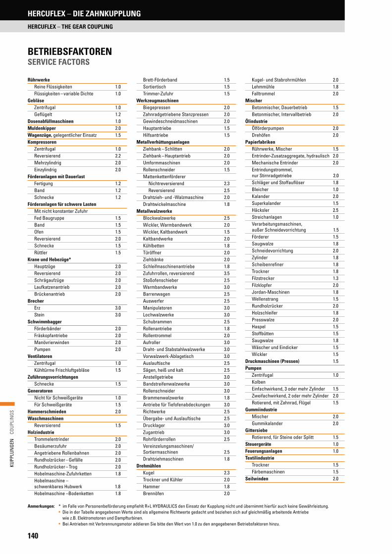
140
KUPP
LUN
GEN
C
OUPL
INGS
HERCUFLEX – DIE ZAHNKUPPLUNG
HERCUFLEX – THE GEAR COUPLING
Rührwerke Reine Flüssigkeiten 1.0 Flüssigkeiten – variable Dichte 1.0
Gebläse Zentrifugal 1.0 Geflügelt 1.2
Dosenabfüllmaschinen 1.0Muldenkipper 2.0Wagenzüge, gelegentlicher Einsatz 1.5Kompressoren
Zentrifugal 1.0 Reversierend 2.2 Mehrzylindrig 2.0 Einzylindrig 2.0
Förderanlagen mit Dauerlast Fertigung 1.2 Band 1.2 Schnecke 1.2
Förderanlagen für schwere Lasten Mit nicht konstanter Zufuhr Fed Baugruppe 1.5 Band 1.5 Ofen 1.5 Reversierend 2.0 Schnecke 1.5 Rüttler 1.5
Krane und Hebezüge* Hauptzüge 2.0 Reversierend 2.0 Schrägaufzüge 2.0 Laufkatzenantrieb 2.0 Brückenantrieb 2.0
Brecher Erz 3.0 Stein 3.0
Schwimmbagger Förderbänder 2.0 Fräskopfantriebe 2.0 Manövrierwinden 2.0 Pumpen 2.0
Ventilatoren Zentrifugal 1.0 Kühltürme Frischluftgebläse 1.5
Zuführungsvorrichtungen Schnecke 1.5
Generatoren Nicht für Schweißgeräte 1.0 Für Schweißgeräte 1.5
Hammerschmieden 2.0Waschmaschinen
Reversierend 1.5Holzindustrie
Trommelentrinder 2.0 Besäumerzufuhr 2.0 Angetriebene Rollenbahnen 2.0 Rundholzrücker – Gefälle 2.0 Rundholzrücker – Trog 2.0 Hobelmaschine-Zufuhrketten 1.8 Hobelmaschine –
schwenkbares Hubwerk 1.8 Hobelmaschine –Bodenketten 1.8
Brett-Förderband 1.5 Sortiertisch 1.5 Trimmer-Zufuhr 1.5
Werkzeugmaschinen Biegepressen 2.0 Zahnradgetriebene Stanzpressen 2.0 Gewindeschneidmaschinen 2.0 Hauptantriebe 1.5 Hilfsantriebe 1.5
Metallverhüttungsanlagen Ziehbank – Schlitten 2.0 Ziehbank – Hauptantrieb 2.0 Umformmaschinen 2.0 Rollenschneider 1.5 Mattenkettenförderer Nichtreversierend 2.3 Reversierend 2.5 Drahtzieh- und -Walzmaschine 2.0 Drahtwickelmaschine 1.8
Metallwalzwerke Blockwalzwerke 2.5 Wickler, Warmbandwerk 2.0 Wickler, Kaltbandwerk 1.5 Kaltbandwerke 2.0 Kühlbetten 1.8 Türöffner 2.0 Ziehbänke 2.0 Schleifmaschinenantriebe 1.8 Zufuhrrollen, reversierend 3.5 Stoßofenschieber 2.5 Warmbandwerke 3.0 Barrenwagen 2.5 Auswerfer 2.5 Manipulatoren 3.0 Lochwalzwerke 3.0 Schubrammen 2.5 Rollenantriebe 1.8 Rollentrommel 2.0 Aufroller 3.0 Draht- und Stabstahlwalzwerke 3.0 Vorwalzwerk-Ablagetisch 3.0 Auslauftische 2.5 Sägen, heiß und kalt 2.5 Anstellgetriebe 3.0 Bandstreifenwalzwerke 3.0 Rollenschneider 3.0 Brammenwalzwerke 1.8 Antriebe für Tiefofenabdeckungen 3.0 Richtwerke 2.5 Übergabe- und Auslauftische 2.5 Drucklager 3.0 Zugantrieb 3.0 Rohrförderrollen 2.5 Vereinzelungsmaschinen/ Sortiermaschinen 2.5 Drahtziehmaschinen 1.8
Drehmühlen Kugel 2.3 Trockner und Kühler 2.0 Hammer 1.8 Brennöfen 2.0
Kugel- und Stabrohrmühlen 2.0 Lehmmühle 1.8 Falltrommel 2.0
Mischer Betonmischer, Dauerbetrieb 1.5 Betonmischer, Intervallbetrieb 2.0
Ölindustrie Ölförderpumpen 2.0 Drehöfen 2.0
Papierfabriken Rührwerke, Mischer 1.5 Entrinder-Zusatzaggregate, hydraulisch 2.0 Mechanische Entrinder 2.0 Entrindungstrommel,
nur Stirnradgetriebe 2.0 Schläger und Stoffauflöser 1.8 Bleicher 1.0 Kalander 2.0 Superkalander 1.5 Häcksler 2.5 Streichanlagen 1.0 Verarbeitungsmaschinen,
außer Schneidevorrichtung 1.5 Förderer 1.5 Saugwalze 1.8 Schneidevorrichtung 2.0 Zylinder 1.8 Scheibenrefiner 1.8 Trockner 1.8 Filzstrecker 1.3 Filzklopfer 2.0 Jordan-Maschinen 1.8 Wellenstrang 1.5 Rundholzrücker 2.0 Holzschleifer 1.8 Presswalze 2.0 Haspel 1.5 Stoffbütten 1.5 Saugwalze 1.8 Wäscher und Eindicker 1.5 Wickler 1.5
Druckmaschinen (Pressen) 1.5Pumpen
Zentrifugal 1.0 Kolben Einfachwirkend, 3 oder mehr Zylinder 1.5 Zweifachwirkend, 2 oder mehr Zylinder 2.0 Rotierend, mit Zahnrad, Flügel 1.5
Gummiindustrie Mischer 2.0 Gummikalander 2.0
Gittersiebe Rotierend, für Steine oder Splitt 1.5
Steuergeräte 1.0Feuerungsanlagen 1.0Textilindustrie
Trockner 1.5 Färbemaschinen 1.5
Seilwinden 2.0
Anmerkungen: * im Falle von Personenbeförderung empfiehlt R+L HYDRAULICS den Einsatz der Kupplung nicht und übernimmt hierfür auch keine Gewährleistung. • Die in der Tabelle angegebenen Werte sind als allgemeine Richtwerte gedacht und beziehen sich auf gleichmäßig arbeitende Antriebe
wie z.B. Elektromotoren und Dampfturbinen. • Bei Antrieben mit Verbrennungsmotor addieren Sie bitte den Wert von 1.0 zu den angegebenen Betriebsfaktoren hinzu.
BETRIEBSFAKTOREN SERVICE FACTORS

141
KUPP
LUN
GEN
C
OUPL
INGS
Agitators Pure liquids 1.0 Liquids – variable density 1.0
Blowers Centrifugal 1.0 Lobe 1.2
Can filling machines 1.0Car dumpers 2.0Car pullers, intermittent duty 1.5Compressors
Centrifugal 1.0 Reciprocating 2.2 Multi cylinder 2.0 Single cylinder 2.0
Conveyors, uniformly loaded or fed Assembly 1.2 Belt 1.2 Screw 1.2
Conveyors, heavy duty Not uniformly Fed assembly 1.5 Belt 1.5 Oven 1.5 Reciprocating 2.0 Screw 1.5 Shaker 1.5
Cranes and hoists*
Main hoists 2.0 Reversing 2.0 Skip hoists 2.0 Trolley drive 2.0 Bridge drive 2.0
Crushers Ore 3.0 Stone 3.0
Dredges Conveyors 2.0 Cutter head drives 2.0 Maneuvering winches 2.0 Pumps 2.0
Fans Centrifugal 1.0 Cooling towers forced draft 1.5
Feeders Screw 1.5
Generators Not welding 1.0 Welding 1.5
Hammer mills 2.0Laundry washers
Reversing 1.5Lumber industry
Barkers – drum type 2.0 Edger feed 2.0 Live rolls 2.0 Log haul – incline 2.0 Log haul – well type 2.0 Planer feed chains 1.8 Planer tilting hoist 1.8 Planer floor chains 1.8
Slab conveyor 1.5 Sorting table 1.5 Trimmer feed 1.5
Machine tools Bending roll 2.0 Punch press, gear driven 2.0 Tapping machines 2.0 Main drives 1.5 Auxiliary drives 1.5
Metal mills Draw bench – carriage 2.0 Draw bench – main drive 2.0 Forming machines 2.0 Slitters 1.5
Table conveyors Non-reversing 2.3 Reversing 2.5
Wire drawing & flattening machine 2.0 Wire winding machine 1.8
Metal rolling mills Blooming mills 2.5 Coilers, hot mill 2.0 Coilers, cold mill 1.5 Cold mills 2.0 Cooling beds 1.8 Door openers 2.0 Draw benches 2.0 Edger drives 1.8 Feed rolls, reversing mills 3.5 Furnace pushers 2.5 Hot mills 3.0 Ingot cars 2.5 Kick-outs 2.5 Manipulators 3.0 Piercers 3.0 Pusher rams 2.5 Reel drives 1.8 Reel drums 2.0 Reelers 3.0 Rod and bar mills 3.0 Roughing mill delivery table 3.0 Runout tables 2.5 Saws, hot & cold 2.5 Screwdown drives 3.0 Skelp mills 3.0 Slitters 3.0 Slabing mills 1.8 Soaking pit cover drives 3.0 Straighteners 2.5 Tables, transfer & runout 2.5 Thrust block 3.0 Traction drive 3.0 Tube conveyor rolls 2.5 Unscramblers 2.5 Wire drawing 1.8
Mills, rotary type Ball 2.3 Dryers & coolers 2.0 Hammer 1.8 Kilns 2.0
Pebble & rod 2.0 Pug 1.8 Tumbling barrels 2.0
Mixers Concrete mixers, continuous 1.5 Concrete mixers, intermittent 2.0
Oil Industry Oil well pumping 2.0 Rotary kilns 2.0
Paper mills Agitators, mixers 1.5 Barker auxiliaries, hydraulic 2.0 Barker mechanical 2.0 Barking drum spur Gear only 2.0 Beater & pulper 1.8 Bleacher 1.0 Calenders 2.0 Calenders, super 1.5 Chippers 2.5 Coaters 1.0 Converting machines, except Cutters, Platters 1.5 Conveyors 1.5 Couch roll 1.8 Cutters 2.0 Cylinders 1.8 Disc refiners 1.8 Dryers 1.8 Felt stretcher 1.3 Felt whipper 2.0 Jordans 1.8 Line shaft 1.5 Log haul 2.0 Pulp grinder 1.8 Press roll 2.0 Reel 1.5 Stock chests 1.5 Suction roll 1.8 Washers & thickeners 1.5 Winders 1.5
Printing presses 1.5Pumps
Centrifugal 1.0 Reciprocating Single acting 3 or more cylinders 1.5 Double acting 2 or more cylinders 2.0 Rotary, gear type, lobe vane 1.5
Rubber Industry Mixer 2.0 Rubber calender 2.0
Screens Rotary, stone or gravel 1.5
Steering gear 1.0Stokers 1.0Textile industry
Dryers 1.5 Dyeing machinery 1.5
Windlass 2.0
Notes: * If people are transported, R+L HYDRAULICS does not recommend and will not warranty the use of the coupling.• Values contained in the table should be used as a general guide and are to be applied to smooth power sources such as electric motors and steam turbines.
• For drives involving internal combustion engines add 1.0 to the values listed.
HERCUFLEX – DIE ZAHNKUPPLUNG
HERCUFLEX – THE GEAR COUPLING
BETRIEBSFAKTOREN SERVICE FACTORS

142
KUPP
LUN
GEN
C
OUPL
INGS
Mit Hilfe der „Finite-Elemente-Methode” wurde die HercuFlex-Kupplung revolutioniert: Höheres Nenndrehmoment, größerer maximaler Bohrungsdurchmesser und längere Lebensdauer sind nur einige Vorteile. Die HercuFlex-Kupplung ist standardmäßig mit einer AGMA-Flanschschnittstelle ausgestattet, um die Austauschbarkeit in den Anwendungen zu gewährleisten.
FX SERIE FX SERIESS
Größe Size
Drehmoment Nominal torque
Max. Bohrung Max. bore
Max. DrehzahlMax. speed
[1/min]
[Nm] [mm] Ungewuchtet/Unbal Gewuchtet/Bal
1.0 1277 48 6000 9000
1.5 2949 62 5500 8250
2.0 5067 78 5000 7500
2.5 9005 92 4400 6600
3.0 15332 108 4000 6000
3.5 22998 127 3500 5250
4.0 35199 149 3000 4500
4.5 48296 171 2700 4050
5.0 66084 197 2500 3750
5.5 87145 220 2200 3300
6.0 136429 241 2100 3150
7.0 185154 287 2000 3000
• Large bore dimensions and high torque capacity• 1.5° misalignment per gear mesh• Screws with improved corrosion resistance • Reworked seal system provides improved protection
against internal contamination of the coupling• Standardised AGMA flange interface for easy replacement
The finite element method was used to revolutionise the HercuFlex coupling, which now offers higher nominal torque, larger maximum bore diameter and longer service life, to name a few benefits. The HercuFlex coupling is fitted with an AGMA flange interface as standard, making interchanging and replacement easy.
• Große Bohrungsabmessungen und hohe Drehmomentenaufnahme • 1,5° Versatz pro Verzahnungsebene• Verbesserte Korrosionsbeständigkeit der Schrauben• Überarbeitetes Dichtungsringkonzept für verbesserten
Schutz gegen innere Verschmutzung der Kupplung• Leichte Austauschbarkeit durch genormte AGMA Flanschschnittstelle
HERCUFLEX – DIE ZAHNKUPPLUNG
HERCUFLEX – THE GEAR COUPLING
KUPPLUNG MIT GEFLANSCHTER HÜLSEFLANGED STYLE COUPLING
PRODUKTEIGENSCHAFTENFEATURES

143
KUPP
LUN
GEN
C
OUPL
INGS
GrößeSize
Abmessungen Dimensions
[mm]
OAL OAL 1 OAL 2 LTB HD D FD TS CL P P1 G G1 G2
1.0 89.2 97.0 104.9 42.9 63.3 82.8 115.8 54.1 1.7 0.3 8.1
3.3
11.2 19.1
1.5 101.9 108.0 114.0 49.3 83.5 104.3 152.4 58.7 1.8 3.0 9.1 9.4 15.5
2.0 127.3 144.5 161.8 62.0 106.9 129.6 177.8 82.6 1.8 3.0 20.3 20.6 37.8
2.5 158.8 178.6 198.4 77.0 126.4 156.6 212.9 101.6 2.6 4.6 24.44.8
24.6 44.5
3.0 187.2 204.2 221.2 91.2 149.4 182.0 239.8 113.0 2.3 9.4 26.4 21.8 38.9
3.5 219.2 233.7 248.2 106.4 174.5 212.2 279.4 127.3 2.4 12.7 27.26.4
20.8 35.3
4.0 247.7 265.2 282.7 120.7 205.7 249.8 317.5 144.5 3.4 15.7 33.3 23.9 41.4
4.5 277.6 304.5 331.5 134.9 230.9 274.7 346.2 169.7 3.5 16.5 43.4
7.9
34.8 61.7
5.0 314.2 348.5 382.8 153.2 260.0 308.0 388.9 195.3 5.0 16.5 50.7 42.2 76.5
5.5 358.9 389.9 420.9 175.5 286.5 333.4 425.5 214.4 4.9 26.9 57.9 38.9 69.8
6.0 384.3 420.1 455.9 188.2 312.2 365.2 457.2 231.9 4.0 22.9 58.7 43.7 79.5
7.0 451.1 484.4 517.7 220.7 363.3 423.9 527.1 263.7 4.8 38.0 71.2 9.7 42.9 76.2
Normale Nabenanordnung Normal hub arrangement
Eine Nabe umgedrehtOne hub reversed
Zwei Naben umgedrehtTwo hubs reversed
HERCUFLEX – DIE ZAHNKUPPLUNG
HERCUFLEX – THE GEAR COUPLING
G
LTB
Ø HD Ø FDØ D
OAL
OAL
LTB
TSCL P
G G 1
LTB
P 1
OAL 1TS
CL
G 2
LTB
P 1
OAL 2TS
CL
ABMESSUNGEN (STANDARD-NABEN)DIMENSIONS (STANDARD HUBS)

144
KUPP
LUN
GEN
C
OUPL
INGS
Innerhalb der HercuFlex-Baureihe gibt es auch die Variante mit einer durchgehenden Hülse. Die CX-Variante verwendet das gleiche branchen- führende Design wie die FX-Variante. In das CX-Segment wurden mehrere Neuerungen eingebaut, um größere Bohrungsdurchmesser und Dreh-momentkapazitäten zu ermöglichen.
CX SERIE CX SERIES
• Große Bohrungsabmessungen und hohe Drehmomentenaufnahme• 1,5° Versatz pro Verzahnungsebene• Überarbeitetes Dichtungsringkonzept bietet verbesserten Schutz gegen
innere Verschmutzung der Kupplung
Größe Size
Drehmoment Nominal torque
Max. Bohrung Max. bore
Max. DrehzahlMax. speed
[1/min]
[Nm] [mm] Ungewuchtet/Unbal Gewuchtet/Bal
1.0 1277 48 6000 9000
1.5 2949 62 5500 8250
2.0 5067 78 5000 7500
2.5 9005 92 4400 6600
3.0 15332 108 4000 6000
3.5 22998 127 3500 5250
4.0 35199 149 3000 4500
4.5 48296 171 2700 4050
5.0 66084 197 2500 3750
5.5 87145 220 2200 3300
6.0 136429 241 2100 3150
7.0 185154 287 2000 3000
The HercuFlex series also includes a version with a continuous sleeve. The CX version uses the same industry-best design as the FX version. A number of new features have been created into the CX range to permit greater bore diameters and higher torque capacities.
• Large bore dimensions and high torque capacity • 1.5° misalignment per gear mesh• Reworked seal system provides improved protection
against internal contamination of the coupling
KUPPLUNG MIT DURCHGEHENDER HÜLSECONTINUOUS SLEEVE STYLE COUPLING
PRODUKTEIGENSCHAFTENFEATURES
HERCUFLEX – DIE ZAHNKUPPLUNG
HERCUFLEX – THE GEAR COUPLING

145
KUPP
LUN
GEN
C
OUPL
INGS
GrößeSize
Abmessungen Dimensions
[mm]
OAL OAL 1 OAL 2 LTB HD OD TS P P1 G G1 G2 LS CL
1.0 92.2 100.1 108.0 42.9 63.3 82.8 54.1 -3.0 4.83.3
11.2 19.1 92.2
1.51.5 101.9 108.0 114.0 49.3 83.5 104.3 58.7 1.3 7.4 9.4 15.5 98.92.0 127.3 144.5 161.8 62.0 106.9 129.6 82.6 0.0 17.3 20.6 37.8 126.92.5 158.8 178.6 198.4 77.0 126.4 156.6 101.6 2.6 22.4
4.824.6 44.5 153.3
3.0 187.2 204.2 221.2 91.2 149.4 182.0 113.0 9.3 26.3 21.8 38.9 168.33.5 219.2 233.7 248.2 106.4 174.5 212.2 127.3 16.7 31.2 6.4 20.8 35.3 185.6
2.34.0 247.7 265.2 282.7 120.7 205.7 249.8 144.5 19.5 37.0 6.4 23.9 41.4 208.54.5 277.6 304.5 331.5 134.9 230.9 274.7 169.7 17.3 44.2
7.9
34.8 61.7 242.75.0 314.2 348.5 382.8 153.2 260.0 308.0 195.3 15.3 49.6 42.2 76.5 283.3
3.25.5 358.9 389.9 420.9 175.5 286.5 333.4 214.4 25.0 55.9 38.9 69.8 308.76.0 384.3 420.1 455.9 188.2 312.2 365.2 231.9 20.9 56.7 43.7 79.5 342.37.0 451.1 484.4 517.7 220.7 363.3 423.9 263.7 37.0 70.3 9.7 42.9 76.2 376.8
ABMESSUNGEN (STANDARD-NABEN)DIMENSIONS (STANDARD HUBS)
OALLS
GLTB Ø HD
Ø OD
Normale Nabenanordnung Normal hub arrangement
Eine Nabe umgedrehtOne hub reversed
Zwei Naben umgedrehtTwo hubs reversed
OALTS
CL
G
LTB
P
OAL 1TS
G 1
CL
LTB
P 1
OAL 2TS
G 2
CL
LTB
P 1
HERCUFLEX – DIE ZAHNKUPPLUNG
HERCUFLEX – THE GEAR COUPLING
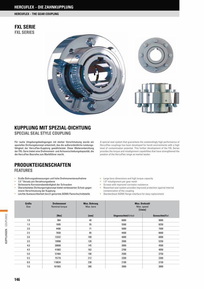
146
KUPP
LUN
GEN
C
OUPL
INGS
HERCUFLEX – DIE ZAHNKUPPLUNG
HERCUFLEX – THE GEAR COUPLING
FXL SERIE FXL SERIES
Größe Size
Drehmoment Nominal torque
Max. Bohrung Max. bore
Max. DrehzahlMax. speed
[1/min]
[Nm] [mm] Ungewuchtet/Unbal Gewuchtet/Bal
1.0 904 40 6000 9000
1.5 1695 55 5500 8250
2.0 4406 71 5000 7500
2.5 7830 85 4400 6600
3.0 13332 100 4000 6000
3.5 19998 120 3500 5250
4.0 30608 145 3000 4500
4.5 41883 162 2700 4050
5.0 57464 190 2500 3750
5.5 75779 212 2200 3300
6.0 118634 238 2100 3150
7.0 161003 280 2000 3000
A special seal system that guarantees the outstandingly high performance of HercuFlex couplings has been developed for harsh environments with a high level of contamination potential. This further development of the FXL Series provides the torque and misalignment capabilities that have strengthened the position of the HercuFlex range as market leader.
• Large bore dimensions and high torque capacity • 1.5° misalignment per gear mesh • Screws with improved corrosion resistance • Reworked seal system provides improved protection against internal
contamination of the coupling • Standardised AGMA flange interface for easy replacement
Für rauhe Umgebungsbedingungen mit starker Verschmutzung wurde ein spezielles Dichtungskonzept entwickelt, das die außerordentliche Leistungs- fähigkeit der HercuFlex-Kupplung gewährleistet. Diese Weiterentwicklung der FXL-Serie bietet eine Drehmoment- und Achsverschiebungskapazität, die die HercuFlex-Baureihe zum Marktführer macht.
• Große Bohrungsabmessungen und hohe Drehmomentenaufnahme• 1,5 ° Versatz pro Verzahnungsebene• Verbesserte Korrosionsbeständigkeit der Schrauben• Überarbeitetes Dichtungsringkonzept bietet verbesserten Schutz gegen
innere Verschmutzung der Kupplung• Leichte Austauschbarkeit durch genormte AGMA Flanschschnittstelle
KUPPLUNG MIT SPEZIAL-DICHTUNGSPECIAL SEAL STYLE COUPLING
PRODUKTEIGENSCHAFTENFEATURES

147
KUPP
LUN
GEN
C
OUPL
INGS
HERCUFLEX – DIE ZAHNKUPPLUNG
HERCUFLEX – THE GEAR COUPLING
GrößeSize
Abmessungen Dimensions
[mm]
OAL LTB HD OD TS G FD CL P
1.0 92.2 42.9 52.3 82.8 54.1
3.3
115.8
1.8
0.3
1.5 101.9 49.3 72.4 104.3 58.7 152.4 3.0
2.0 127.3 62.0 95.2 129.6 82.6 177.8 3.0
2.5 158.8 77.0 114.0 156.6 101.64.8
212.9 2.6 4.6
3.0 187.2 91.2 136.6 182.0 113.0 239.8 2.3 9.4
3.5 219.2 106.4 161.1 212.2 127.36.4
279.4 2.4 12.7
4.0 247.7 120.7 188.3 249.8 144.5 317.5 3.4 15.7
4.5 277.6 134.9 212.8 274.7 169.7
7.9
346.2 3.5 16.5
5.0 314.2 153.2 241.5 308.0 195.3 388.9 5.0 16.5
5.5 358.9 175.5 267.3 333.4 214.4 425.5 4.9 26.9
6.0 384.3 188.2 293.5 365.2 231.9 457.2 4.0 22.9
7.0 451.1 220.7 343.8 423.9 263.7 9.7 527.1 4.8 38.0
ABMESSUNGEN (STANDARD-NABEN)DIMENSIONS (STANDARD HUBS)
Normale Nabenanordnung Normal hub arrangement
OALTS
G
W
LTBOD
FDHDØ
OALTS
CL
G
LTB
P
ØØ

148
KUPP
LUN
GEN
C
OUPL
INGS
HERCUFLEX – DIE ZAHNKUPPLUNG
HERCUFLEX – THE GEAR COUPLING
• Axiale Positionierung des Pumpenlaufrades bei vertikal montierten Pumpen
• Leichter Einbau und einfache Wartung für Pumpe bzw. Motor, da die Bohrungen mit Spielpassungen ausgeführt werden
• Leichte Justierbarkeit durch Einstellbarkeit des vertikalen Abstandes• Einfache Wartung durch herausnehmbares Abstandsstück• AISI 1045 Stahl• Kupplung ist auch in Edelstahl verfügbar
GrößeSize
DrehmomentNominal torque
SchubkraftThrust capacity
Motor- und Pumpennabe Motor & pump hubs
Min. Bohrung Min. bore
Max Bohrung Max. bore
[Nm] [kN] [mm] [mm]
1125 192 20.02 11 29
1625 570 48.93 16 41
2125 1275
137.89
18 54
2625 240722
67
2875 3162 73
3125 4059 182.38 30 79
3875 7762 324.72 31 98
5000 22075 711.72 60 127
6000 28768 1334.47 73 152
7250 50701 1334.47101
184
8500 81748 1556.88 216
10500 154096 1779.29 127 267
RA UND RAHS SERIERA AND RAHS SERIES
Notwendige Angaben zur Kupplungsauswahl• Motorleistung oder Drehmomentenangabe
des Motors• Motordrehzahl oder Drehzahl der
Abtriebsseite (U/min)• Abstand zwischen den beiden Wellenenden
(BSE)• Wellendurchmesser und Wellenlänge• Gewinde der Stellmutter• zu übertragende Axialkraft• falls verfügbar können Zeichnungen
beigefügt werden• RAHS Kupplungen stimmen mit der Norm
API 610 überein.
• Axial positioning of pump impeller for vertically mounted pumps • Clearance-fit bores for easy fitting and maintenance of pump and motor • Vertical clearance can be set for easy adjustment • Removable spacer for easy maintenance • AISI 1045 steel • Coupling also available in stainless steel
Data required for coupling selection• Motor rating or motor torque • Motor speed or speed of driven side (RPM) • Space between the the two shaft ends (BSE) • Shaft diameter and end of shaft length• Thread of setting nut • Transmitted axial force • Drawings may be attached if available• RAHS couplings comply with standard API 610.
LABYRINTHDICHTUNG MIT FLANSCH VARIANTEFLANGED LABYRINTH SEAL STYLE COUPLING
Two different styles of the RA and RAHS couplings are available: Style II consists of two rigid hubs, setting nut and split ring for the motor hub. Style IV consists of two rigid hubs, setting nut, split ring for the motor hub and a spacer.
Die RA und RAHS Kupplung werden in zwei verschiedenen Varianten ange-boten: Variante II besteht aus zwei starren Naben, Stellmutter und Spaltring für die Motornabe. Variante IV besteht aus zwei starren Naben, Stellmutter und Spaltring für die Motornabe und ein Abstandsstück.
PRODUKTEIGENSCHAFTENFEATURES

149
KUPP
LUN
GEN
C
OUPL
INGS
HERCUFLEX – DIE ZAHNKUPPLUNG
HERCUFLEX – THE GEAR COUPLING
Position Item Beschreibung Description
1 Nabe auf Motorseite Upper hub – motor
2 Nabe auf Pumpenseite Lower hub – pump
3 Distanzstück Spacer
4 Stellmutter Adjusting nut, threaded
5 Scheibe Washer, split
6 RA und RAHS Zubehörteile RA and RAHS accessory kit
7 RA und RAHS Zubehörteile RA and RAHS accessory kit
GrößeSize
Abmessungen Dimensions
[mm]
Schrauben Bolts
B.C. Ø
STD OAL S AnzahlQuantity
GrößeSize
[Zoll/in]Type II Type IV FD D LTB LTB1 LS DC SL D1 D2 Standard Min [mm]
1125 133.35 242.82 76.20 44.45 54.10 28.19 50.80 22.61 22.35 44.45 31.75
112.78
41.40 4 1/4 – 28 60.33
1625 152.40 261.87 101.60 63.50 60.45 34.54 57.15 22.61 22.35 63.50 44.45 44.45
6
5/16 – 24 82.55
2125 181.10 290.58 130.30 79.50 71.37 45.72 68.33 22.61 25.40 79.50 57.15 66.80
1/2 – 20
107.95
2625 238.25 347.73 149.35 98.55 77.72 52.07 74.68 22.61 28.70 98.55 69.85 66.80 125.43
2875 263.65 373.13 162.05 111.25 90.42 64.77 87.38 22.61 35.05 111.25 76.20 73.15 138.13
3125 292.10 401.57 171.45 117.60 104.90 78.99 101.60 22.61 41.40 117.60 82.55 73.15 8 147.65
3875 323.85 433.32 227.08 149.35 114.30 88.39 111.25 22.61 44.45 149.35 101.60 79.50 6 3/4 – 16 193.68
5000 381.00
–
298.45 190.50 158.75 117.60 152.40 35.05 61.98 190.50 130.30
–
114.30 8
1 – 14
254.00
6000 530.35 336.55 228.60 241.30 193.80 234.95 41.40 101.60 228.60 155.70 120.65 10 292.10
7250 639.83 381.00 273.05 280.92 223.77 273.05 49.28 120.65 273.05 187.45 179.32 14 336.55
7500 852.42 438.15 317.50 388.87 331.72 381.00 49.28 168.40 317.50 219.20 185.6712
1-1/8 – 12 381.00
10500 1039.88 520.70 381.00 474.73 417.58 466.85 49.28 206.50 381.00 270.00 211.07 1-1/8 – 12 457.20
RA & RAHS Kupplungstyp IIRA & RAHS coupling type II
RA & RAHS Kupplungstyp IVRA & RAHS coupling type IV
ABMESSUNGENDIMENSIONS
3
4
6
2
D
LTB1
DC
D2
LS
S
OAL
D1
LSLTB
FDSL
1
5
7

150
KUPP
LUN
GEN
C
OUPL
INGS
HERCUFLEX – DIE ZAHNKUPPLUNG
HERCUFLEX – THE GEAR COUPLING
VARIANTEN VON HERCUFLEX ZAHNKUPPLUNGEN MIT DURCHGEHENDER HÜLSEVARIETY OF HERCUFLEX GEAR COUPLING TYPES WITH CONTINUOUS SLEEVE
Kupplungsvariante für den vertikalen EinbauDer obere Teil der Kupplung ist aus dem Standard-Produktprogramm der vertikalen Zahnkupplungen entnommen. In der Platte der unteren Nabe der unteren Kupplung ist ein gehärteter balliger Butzen; in der Platte der oberen Nabe ist ein gehärteter flacher Butzen. Diese zwei Butzen tragen das gesamte Gewicht der schwimmenden Baugruppe; somit bleibt der Abstand zwischen den zwei unteren Naben konstant, was die Flexibilität ermöglicht. Die Naben auf der Seite der schwimmenden Welle sind flexibel, die Naben auf der Seite der treibenden und der angetriebenen Welle sind starr.
Coupling version for vertical mountingThe upper section of the coupling comes from the standard product range of vertical gear couplings. There is a hardened crowned button in the plate of the lower hub of the lower coupling, and a hardened flat button in the plate of the upper hub. These two buttons support the entire weight of the floating sub-assembly, so the clearance between the two lower hubs remain constant, thus permitting flexibility. The hubs on the floating shaft side are flexible; those on the driving and driven shaft side are rigid.
VERTIKALE VARIANTE MIT SCHWIMMENDER WELLE VERTICAL FLOATING SHAFT TYPE
BREMSTROMMEL-VARIANTE BRAKE DRUM TYPE
Es sind zwei verschiedene Bremstrommel-Varianten abgebildet. Die linke Abbildung zeigt die Kupplung mit zwei Standardnaben und einer in die Hülse integrierten Bremstrommel. Die Ausführung rechts besteht aus einer Standardnabe und einer Standardhülse, wobei die Bremstrommel in die zweite Nabe integriert ist.
The illustrations show two different brake drum types. The illustration on the left shows the coupling with two standard hubs and a brake drum integrated in the sleeve. The type shown on the right consists of a standard hub and a standard sleeve, with the brake drum integrated in the second hub.

151
KUPP
LUN
GEN
C
OUPL
INGS
HERCUFLEX – DIE ZAHNKUPPLUNG
HERCUFLEX – THE GEAR COUPLING
BREMSSCHEIBEN-VARIANTE BRAKE DISC TYPE
Es sind zwei verschiedene Bremsscheiben-Varianten abgebildet. Die linke Abbildung zeigt die Kupplung mit zwei Standardnaben und einer in die Hülse integrierte Bremsscheibe. Die Ausführung rechts besteht aus einer Standardnabe und einer Standardhülse, wobei die Bremsscheibe in die zweite Nabe integriert ist.
The illustrations show two different brake disc types. The illustration on the left shows the coupling with two standard hubs and a brake disc integrated in the sleeve. The type shown on the right consists of a standard hub and a standard sleeve, with the brake disc integrated in the second hub.
GLEITNABEN-VARIANTE SLIDING HUB TYPE
Die Gleitnaben-Variante ist entwickelt worden, um große axiale Bewegungen ausgleichen zu können. Die Hülse und eine Nabe sind hierbei länger als bei der Standardausführung, was die axiale Verschiebung zulässt. Die andere kurze Nabe wird mit einer Distanzscheibe und einem Klemmring an der Hülse befestigt, um unerwünschte Bewegung zu vermeiden. Diese Kupplungsart ist auch mit zwei beweglichen Naben erhältlich. Dabei ist das axiale Verschieben für beide Naben begrenzt.
The sliding hub type was developed to enable large axial movements. Here, the sleeve and one hub are longer than in the standard type, allowing axial displacement. The other short hub is fixed to the sleeve with a spacer washer and a clamping ring to prevent undesirable movement. This type of coupling is also available with two movable hubs, although axial displacement for both hubs is then limited.
VARIANTEN VON HERCUFLEX ZAHNKUPPLUNGEN MIT DURCHGEHENDER HÜLSEVARIETY OF HERCUFLEX GEAR COUPLING TYPES WITH CONTINUOUS SLEEVE

152
KUPP
LUN
GEN
C
OUPL
INGS
HERCUFLEX – DIE ZAHNKUPPLUNG
HERCUFLEX – THE GEAR COUPLING
VARIANTEN VON HERCUFLEX ZAHNKUPPLUNGEN MIT DURCHGEHENDER HÜLSEVARIETY OF HERCUFLEX GEAR COUPLING TYPES WITH CONTINUOUS SLEEVE
Dieses Modell ist für den Einsatz in Jordan-Maschinen und Mahlmaschinen gedacht. Sie ist der Gleitnabenkupplung ähnlich. Der Unterschied zwischen den beiden Varianten ist, dass die lange Nabe der Jordan-Variante geteilt ist und mit einer Schraube an der Welle befestigt wird. Somit ist eine schnelle axiale Anpassung der Jordanwellen in der Nabe möglich.
This model is designed for use in Jordan machines and refiners. It is similar to the sliding hub coupling, the difference being that the long hub of the Jordan type is split and attached to the shaft with a screw. This allows fast axial adjustment of the Jordan shaft in the hub.
JORDAN-VARIANTE JORDAN TYPE
VARIANTE MIT DAUERSCHMIERUNG CONTINUOUS LUBRICATION TYPE
Dieses Modell ist eine Abwandlung der CX Kupplungsvariante. Hierbei wurden die Dichtungsringe durch spezielle Distanzscheiben ersetzt. Die Distanzscheiben sitzen passgenau in der Hülse, haben jedoch ausreichend Abstand zum Hülsen-Außendurchmesser um kontinuierliches Einspritzen von Schmierstoff zu ermöglichen.
This model is a modified type of the CX coupling, the difference being that the sealing rings have been replaced by special spacer washers. These washers fit snugly inside the sleeve, but there is sufficient clearance between washer and outer diameter of the sleeve to allow the continuous injection of lubricant.

153
KUPP
LUN
GEN
C
OUPL
INGS
HERCUFLEX – DIE ZAHNKUPPLUNG
HERCUFLEX – THE GEAR COUPLING
VARIANTEN VON HERCUFLEX ZAHNKUPPLUNGEN MIT GEFLANSCHTER HÜLSEVARIETY OF HERCUFLEX GEAR COUPLING TYPES WITH FLANGED SLEEVE
VARIANTE MIT AXIALSPIELBEGRENZUNG UND ABSTANDSHALTER LIMITED END FLOAT SPACER TYPE
Die zusätzlichen Platten begrenzen die axiale Bewegung der antreibenden oder der getriebenen Welle. Der Abstandshalter ermöglicht es, die Naben von beiden Wellen zu entfernen, ohne die Applikation zu demontieren.
The additional plates limit the axial movement of the driving or driven shaft. The spacer allows the hubs to be removed from both shafts without dismantling the entire application.
Die schwimmende Welle der Kupplungsbaugruppe wird über eine gehärtete, ballige Halbkugel auf eine Platte übertragen, die auf der unteren Nabe aufliegt. Neben dieser Standardvariante gibt es noch die Möglichkeit – je nach Applikation – die untere Nabe als starre Nabe auszuführen und die so gelagerte Welle über eine flexible Nabe am oberen Ende an den Antrieb anzubinden.
On the hardened crowned button rests the entire floating assembly of the coupling. The hardened crowned button is inserted in the plate of the lower hub. In addition to this standard type, it is also possible – depending on the application – to have a rigid lower hub; a flexible hub at the upper end of the shaft mounted in this way then connects the hub to the drive.
VERTIKALE VARIANTE MIT SCHWIMMENDER WELLE VERTICAL FLOATING SHAFT TYPE
VERTIKALE VARIANTE VERTICAL TYPE
Diese Kupplung verfügt über die gleichen Leistungs- und Verlagerungs-eigenschaften wie die Standard FX Kupplung der jeweiligen Größen. Das Gewicht der Hülse wird über eine gehärtete, ballige Halbkugel auf eine Platte übertragen, die auf der unteren Nabe aufliegt.
The performance and misalignment characteristics of this coupling are the same as those of the respective standard FX couplings of equivalent size. A hardened crowned button transfers the weight of the sleeve to a plate resting on the lower hub.

154
KUPP
LUN
GEN
C
OUPL
INGS
VARIANTEN VON HERCUFLEX ZAHNKUPPLUNGEN MIT GEFLANSCHTER HÜLSEVARIETY OF HERCUFLEX GEAR COUPLING TYPES WITH FLANGED SLEEVE
HERCUFLEX – DIE ZAHNKUPPLUNG
HERCUFLEX – THE GEAR COUPLING
ISOLIERENDE VARIANTE INSULATING TYPE
Zwischen den Flanschen und im Bereich der Schrauben wird ein nichtmetallisches Material verwendet, um etwaige elektrische Ströme von einer Welle zur anderen zu unterbinden.
Non-metallic material is used between the flanges and around the screws to ensure that an electric charge cannot pass one shaft to another.
JORDAN-VARIANTE JORDAN TYPE
Dieses Modell ist für den Einsatz in Jordan-Maschinen und Mahlmaschinen gedacht. Sie ist der Gleitnabenkupplung ähnlich. Der Unterschied zwischen den beiden Varianten ist, dass die lange Nabe der Jordan-Variante geteilt ist und mit einer Schraube an der Welle befestigt ist. Somit ist eine schnelle axiale Anpassung der Jordanwellen in der Nabe möglich.
This model is designed for use in Jordan machines and refiners. It is similar to the sliding hub coupling, the difference being that the long hub of the Jordan type is split and attached to the shaft with a screw. This allows fast axial adjustment of the Jordan shaft in the hub.
VARIANTE MIT SCHERBOLZEN ENGINEERED SHEAR PIN TYPE
Die Scherbolzen-Variante wird vorwiegend dafür verwendet, um das übertragbare Drehmoment begrenzen zu können. Dabei wird die Verbindung zwischen Antriebswelle und angetriebener Welle unterbrochen, wenn das Drehmoment die vorgeschriebene Grenze überschreitet. Solche Kupplungen sind besonders dazu geeignet, die Anlage im Falle einer Blockierung zu schützen. Nach dem Scherbruch können, mit Ausnahme der Scherbolzen, alle Komponenten der Kupplung wieder verwendet werden. Für eine kurze Zeit bleibt genügend Schmierstoff in der Kupplung, so dass die Anlage ausgeschaltet werden kann, ohne Beschädigung an der Kupplung hervorzurufen.
The shear pin type is mainly used to restrict the transmittable torque. This is achieved by interrupting the connection between driving and driven shaft when torque exceeds the predetermined limit. This type of coupling is particularly suitable for protecting the plant in the event of a jam. All coupling components, apart from the shear pins themselves, can be re-used after pins shear. An adequate amount of lubricant remains in the coupling for a short time, enabling the plant to be shut down before any damage is done to the coupling.

155
KUPP
LUN
GEN
C
OUPL
INGS
VARIANTEN VON HERCUFLEX ZAHNKUPPLUNGEN MIT GEFLANSCHTER HÜLSEVARIETY OF HERCUFLEX GEAR COUPLING TYPES WITH FLANGED SLEEVE
HERCUFLEX – DIE ZAHNKUPPLUNG
HERCUFLEX – THE GEAR COUPLING
VARIANTE MIT BREMSTROMMEL ODER -SCHEIBE BRAKE DRUM AND BRAKE DISC TYPE
Bei dieser Variante wird die Bremstrommel oder Bremsscheibe zwischen die Standardhülsen und/oder an der starren Nabe der Kupplung gebaut. Hiermit wird eine einfacherer Austausch der Bremsscheibe und Bremstrommel gewährleistet.
In this type, the brake drum or brake disc is installed between the standard sleeves and/or in the rigid hub of the coupling, thus ensuring easier replacement of the brake disc and brake drum.
DOPPELEINGRIFFSVARIANTE – HALBE ZAHNKUPPLUNG DOUBLE ENGAGEMENT HALF GEAR TYPE
Die innenliegende und außenliegende Verzahnung sind in einer Hülse untergebracht. So eignet sich diese Kupplung vor allem für den Einbau zwischen einem rotierenden Schwungrad oder einer Trommel und einer Welle. Diese Variante bietet die gleichen Leistungs- und Verlagerungseigenschaften wie die entsprechenden Standardkupplungen.
The interior and exterior gear meshes are enclosed in a sleeve, so this coupling is particularly suitable for installation between a rotating flywheel or drum and a shaft. This type offers the same performance and misalignment characteristics as the corresponding standard couplings.
STARRE KUPPLUNGSVARIANTE AUS LEGIERTEM STAHL – FARR-VARIANTE RIGID ALLOY STEEL FARR TYPE
Diese starre Kupplungsvariante ist mit zwei Endplatten versehen, so dass hierdurch eine drehstarre Verbindung realisiert werden kann, die auch axial fixiert ist. Diese Kupplung findet Verwendung zwischen langsam drehenden Wellen von einem Getriebekasten und einer Kopfwelle eines Förderbands, Becherwerks, Mischers oder anderen fliegend gelagerten Wellen.
This rigid coupling type is fitted with two end plates, which allows the realisation of a torsionally rigid connection that is also fixed axially. This coupling is used to connect slowly rotating gearbox shafts and the head shaft of a conveyor, bucket elevator, mixer or other floating shaft assemblies.

156
KUPP
LUN
GEN
C
OUPL
INGS
HERCUFLEX – DIE ZAHNKUPPLUNG
HERCUFLEX – THE GEAR COUPLING
ZUSÄTZLICHE ABMESSUNGENADDITIONAL DIMENSIONAL DATA
45°
H B.C. Ø
GrößeSize
Abmessungen Dimensions
[Zoll/in]
B.C. Ø
H*
UNC TiefeDepth
1.0– – –
1.5
2.0 3.38 5/16 – 18 0.50
2.5 3.94 3/8 – 16 0.56
3.0 4.94 1/2 – 13 0.75
3.5 5.56 1/2 – 13 0.75
4.0 6.44 5/8 – 11 0.94
4.5 7.38 5/8 – 11 0.94
5.0 8.00 3/4 – 10 1.13
5.5 9.00
1 – 81.50
6.0 9.75
7.0 11.63 1.50
GrößeSize
Abmessungen Dimensions
[mm]
Bohrung RSBHD Bore RSB L1 L2 L3 TW LTB* LTB 1**
1.0 63.25
Vollmaterial/Solid
69.85 11.18 19.05 12.70 42.93 101.60
1.5 83.57 79.5014.48
20.57 14.22 49.28 114.30
2.0 106.93 92.20 31.75 15.75 61.98 139.70
2.5 126.2437.34
107.19 19.05 38.86 19.05 76.96 165.10
3.0 149.35 112.52 25.91 42.93 22.35 91.19 177.80
3.5 174.50 46.74 117.35 33.27 47.75 25.40 106.43 190.50
4.0 205.74 62.74 126.24 37.34 54.86 28.45 120.65 209.55
4.5 230.8976.20
131.83 38.10 65.02 31.75 134.87 228.60
5.0 260.10 128.52 40.39 74.68 38.10 153.16 241.30
5.5 286.51101.60
141.22 50.04 81.03 44.45 175.51 266.70
6.0 312.17 143.51 45.97 81.79 60.45 188.21 285.75
7.0 363.22 127.00 177.80 63.50 96.77 60.45 220.73 335.03
* Länge Standard-Nabe Length standard hub** Länge Universal-Nabe Length universal hub
* H bezieht sich auf die Bohrungsform. UNC = Gewinde, Tiefe des Gewindes H refers to the bore form. UNC = thread, depth of thread
ABMESSUNGEN NABE HUB DIMENSIONS
ABZIEHGEWINDEBOHRUNGEN FLEX HUB PULLER BOLT HOLES
HD
LTB 1 Universal-NabeUniversal Hub
L1
L 2L 3
TW
BohrungBore
LTBStandard-NabeStandard Hub

157
KUPP
LUN
GEN
C
OUPL
INGS
HERCUFLEX – DIE ZAHNKUPPLUNG
HERCUFLEX – THE GEAR COUPLING
GrößeSize
Abmessungen Dimensions
[mm]
LS W DC FD CBD CBD 1 L
1.0 42.16 14.22
2.29
115.82 76.96 16.26
6.351.5 47.75 19.05 152.40 99.3120.57
2.0 60.45 19.05 177.80 124.21
2.5 73.1522.35
212.85 147.5726.92 7.87
3.0 84.07 239.78 170.94
3.5 96.77
28.70
279.40 196.34
33.27 9.654.0 107.95
4.83
317.50 229.11
4.5 122.17 346.20 256.03
5.0 139.7038.10
388.87 288.5439.62 14.22
5.5 152.40 425.45 319.53
6.0 169.93 25.40 6.35 457.20 349.25– –
7.0 187.45 28.70 7.87 527.05 402.84
GrößeSize
Anzahl der Schrauben Number of
bolts
Gewinde-größe
THD Size[Zoll/in]
Abmessungen Dimensions
[mm]
B.C. Ø * LengthMinBody
MaxGrip
1.0 6 1/4 – 28 95.25 38.10 16.00 27.00
1.5 8 3/8 – 24 122.22 50.80 22.35 36.53
2.06
1/2 – 20 149.23 57.15 22.35 35.71
2.5 5/8 – 18 180.98 69.85 25.40 42.06
3.0
8
5/8 – 18 206.38 69.85 25.40 118.26
3.5
3/4 – 16
241.30 82.55 31.75 54.76
4.0 279.40 82.55 31.75 54.76
4.5 10 304.80 82.55 31.75 29.36
5.0 8
7/8 – 14
342.90 107.95 42.93 73.03
5.514
368.30 76.20 28.70 44.45
6.0 400.05 82.55 30.23 47.63
7.0 16 1 – 14 463.55 88.90 33.27 53.98
Anzahl der Schrauben Number of bolts
Gewinde-größe
THD Size[Zoll/in]
Abmessungen Dimensions
[mm]
B.C. Ø ** LengthMin
BodyMaxGrip
6 1/4 – 28 95.25 20.57
7.14 11.1383/8 – 24
122.2225.40
10 147.62
101/2 – 20
177.8031.75 9.53 13.49
12 203.20
12
5/8 – 18
235.74
38.10 11.13 16.6614 269.88
14 298.45
143/4 – 16
334.9850.80 15.88 26.19
16 366.70
Nur mit freiliegendem SchraubenkopfExposed bolts only
SCHRAUBENABMESSUNGEN DER VARIANTE MIT VERSENKTEM SCHRAUBENKOPF SHROUDED BOLTS
** Teilkreisdurchmesser der Varianten mit versenktem Schraubenkopf
** Pitch circle diameter of styles with countersunk screw head
* Teilkreisdurchmesser der Varianten mit freiliegendem Schraubenkopf
* Pitch circle diameter of styles with exposed screw head
FD FD
LS
W W
LS
B.C. Ø* B.C. Ø**DC DC
CBD
CBD 1 L
EinspannlängeGrip
Schaft Body
LengthLänge
HÜLSEN- UND SCHRAUBENABMESSUNGEN SLEEVE AND BOLT DIMENSIONS
SCHRAUBENABMESSUNGEN DER VARIANTE MIT FREILIEGENDEM SCHRAUBENKOPF EXPOSED BOLTS

158
KUPP
LUN
GEN
C
OUPL
INGS
NLGI KlasseNLGI Grade 0/1
AussehenAppearance
dunkelbraun, klebrigDark brown, tacky
Viskosität Viscosity
@ 40 °C [cST] 350
@ 100 °C [cST] 10
Tropfpunkt [°C]Dropping point [°C] 160
Zentrifugale Ölabtrennung [Vol %] Centrifugal oil separation [Vol %] None
Verlust durch Spülung mit Wasser [Gew %]
Water spray-off [wt %]>3
Rostschutz Rust protection
GewährleistetPass
Timken, OK Last [N]Timken, OK Load [N] 178+
4-Kugel DrucktestFour-ball EP
Last-Verschleißwert [N]Load wear index [N] 667
Schweißpunkt [N]Weld point [N] 3923
4-Kugel VerschleißtestFour-ball wear
1 Std., 75° C, 1200 U/min, 392 [N]1 hr, 75° C, 1200 RPM, 392 [N] 0.4
EinsatztemperaturenGuide to operating temperature
Minimum [°C]Minimum [°C] -29
Dauerbetrieb, Max. [°C]Continuous service, max. [°C] 121
Kurzzeitspitze, Max. [°C]Short exposure, max. [°C] 163
EIGENSCHAFTEN/VORTEILECHARACTERISTICS/BENEFITS
• Kupplungsabnutzung wird minimiert• Widerstandsfähig gegen Waschwasser• Korrosions- und Rostschutz• Hohe Belastbarkeit • Längere Nachschmierungsintervalle• Einsatztemperaturen bis 163 °C• Haftet selbst bei hohen Geschwindigkeiten• Widerstandsfähig gegen Zentrifugalabtrennung• Minimierung von Stillstandszeiten und Wartungskosten
• Coupling wear is minimised • Resistant to water spray-off • Protection against corrosion and rust • High loading possible • Longer relubrication intervals • Operating temperatures up to 163 °C • Remains adhesive even at high speeds • Resistant to centrifugal separation • Minimises downtime and maintenance costs
KUPPLUNGSFETTCOUPLING GREASE
TYPISCHE EIGENSCHAFTEN DES KUPPLUNGSFETTESTYPICAL PROPERTIES OF GEAR COUPLING GREASE
HERCUFLEX – DIE ZAHNKUPPLUNG
HERCUFLEX – THE GEAR COUPLING
Projektierungsbogen für die Auswahl von HercuFlex Zahnkupp-lungen einfach downloaden unter: www.rl-hydraulics.com
HercuFlex Selection Worksheet: simply download at www.rl-hydraulics.com
SERVICE FÜR UNSERE KUNDENCUSTOMER SERVICE

159
KUPP
LUN
GEN
C
OUPL
INGS
LAMELLENKUPPLUNGEN
DISC COUPLINGS
• Keine Schmierung erforderlich• Ohne Verschleißteile• Zustand der Kupplung lässt sich im laufenden Betrieb ohne Demontage
überprüfen• Torsionssteif und spielfrei• Hohe Leistungsdichte (höheres übertragbares Moment bei vorgege-
benem Außendurchmesser)• Geeignet für raue Umgebungsbedingungen• Atex-Klassifizierung: siehe Seite 173
PRODUKTEIGENSCHAFTENFEATURES
• Eliminates the need for lubrification and coupling maintenance • No wearing parts • Condition of disc packs can be inspected with a strobe light while the
machine is running • Torsionally rigid without any backlash • High power density (higher torque for a given outside diameter)• Resistance to harsh environments • Atex classification: see page 173
Die Lovejoy D-Serie bietet ein breites Sortiment an hochwertigen Lamellen-kupplungen, die an die gestiegenen Anforderungen des Marktes hinsichtlich der übertragbaren Drehmomente und der Lebensdauer angepasst sind.Durch den Einsatz fortschrittlicher Entwurfstechniken, der Finite-Element-Methode und umfassenden Materialtests wurde ein innovatives Lamellen-paket entwickelt, das im Vergleich zu herkömmlichen Lamellenpaketen auf dem Markt revolutionär ist. Es kann – je nach Baugröße – maximale Winkel-abweichungen von 0.5° bis zu 1,5° ausgleichen und kommt in allen Lovejoy D Kupplungen zum Einsatz.Die Lovejoy D Lamellenpakete werden aus Edelstahl (AISI-301) gefertigt. Dies gewährleistet hohe Stabilität, hohen Ermüdungswiderstand und Beständigkeit unter rauen Umgebungsbedingungen.In den Lovejoy D Lamellenkupplungen kommen einheitliche Lamellenpakete mit 4, 6 oder 8 Schrauben zum Einsatz. Sie können auch mit Überlastbuchsen ausgestattet werden, um das Lamellenpaket während kurzzeitiger Torsions-überlast zu schützen.
Lovejoy takes great pride in being able to offer a wide variety of superior disc coupling products in models designed to meet the application needs of today’s worldwide power transmission market.Using advanced design techniques, implementation of Finite Element Analy-sis, and extensive testing of materials, Lovejoy has developed an innovative disc pack profile design revolutionary to traditional disc pack designs found in the market. This disc pack can – depending on the size of coupling – ac-comodate 1/2° to 1–1/2° of angular misalignment, and is used in all Lovejoy disc coupling products.Lovejoy disc packs are manufactured using high grade stainless steel (AISI-301), ensuring high strength, high endurance to fatigue, and resistance to most environmental conditions.Lovejoy disc couplings utilize disc packs with 4, 6 or 8 bolt designs. Lovejoy couplings can also be fitted with overload bushings to protect the disc pack during momentary torsional overloads.
LAMELLENKUPPLUNGEN LOVEJOY SERIE DDISC COUPLINGS LOVEJOY SERIES D

160
KUPP
LUN
GEN
C
OUPL
INGS
Ausführung Version Beschreibung Description
Ausführung SUVersion SU
• Einfache Kupplung mit zwei Naben und einem Lamellenpaket• Nur für den Ausgleich von Winkelabweichungen und axialen Versätzen
geeignet• Durch den Einsatz von zwei SU-Kupplungen und einer Zwischenwelle las-
sen sich auch größere Abstände zwischen zwei Wellenenden überbrücken und auch radiale Versätze ausgleichen
• Single flex plane with two hubs and a single disc pack• For angular and axial misalignment only• Two SU couplings are often combined with a shaft to make a floating shaft
coupling; shaft can be hollow for long light weight floating shaft couplings
Ausführung SXVersion SX
• Lamellenkupplung mit zwei Lamellenpaketen und standardisiertem Zwi-schenstück zum Ausgleich von radialen, axialen Versätzen und Winkelab-weichnungen
• In verschiedenen Baugrößen mit 4 (auf Anfrage), 6 oder 8 Schrauben und Bohrungsdurchmesser bis 235 mm verfügbar
• Individuelle Zwischenstücke und größere Bohrungsdurchmesser auf Anfra-ge erhältlich
• Two flex planes (one at each disc pack) accommodate parallel, angular, and axial misalignment
• Available in 4 (on request), 6 and 8 bolt designs; bore sizes up to 13 inches (235 mm)
• Custom spacer lengths & overload bushing available on request
Ausführung SXCSTVersion SXCST
• Kupplungen mit innenliegenden Naben und geteiltem Zwischenstück. Lamellenpakete können ohne Versetzen der Naben ausgetauscht werden
• Verbindungsschrauben werden im Inneren des Zwischenstücks in Richtung der Naben montiert
• Split spacer couplings, where disc packs can be serviced or removed without moving hubs
• Connecting bolts are installed from inside the spacer outward, pointing towards the hubs
STANDARDAUSFÜHRUNGENSTANDARD VERSIONS
LAMELLENKUPPLUNGEN
DISC COUPLINGS

161
KUPP
LUN
GEN
C
OUPL
INGS
WEITERE AUSFÜHRUNGEN AUF ANFRAGEOTHER VERSIONS ON REQUEST
Ausführung Version Beschreibung Description
Ausführung DIVersion DI
• Kupplung mit Ausbaustück• Das Ausbaustück besteht aus einem Zwischenstück, zwei Lamellen-
paketen und zwei Zwischenflanschen. Es wird komplett vormontiert geliefert und kann ohne Verschieben der Naben montiert werden.
• Zentrierungen an den Naben gewährleisten eine korrekte Führung der Drop-In-Baugruppe und verhindern das Schlagen des Zwischenstücks
• Erfüllt die Anforderungen gem. API-610 bezüglich der Auswuchtgüte und der Führung des Zwischenstücks
• Naben in Übergröße erhältlich – das ermöglicht ggf. die Verwendung von kleineren Kupplungen
• Coupling with “Drop-In” spacer assembly• “Drop-In” spacer assembly coupling; 2 hubs and spacer assembly
(comprising of the spacer, 2 unitized disc packs, and 2 guard rings)• Hubs are piloted - ensures proper centering, as an anti-flail feature• Meets API-610 balance and anti-flail requirements• Oversized hubs available, allows for the use of smaller couplings
where applicable
Ausführung SXCVersion SXC
• Kompakte Variante der Ausführung SX mit innenliegenden Naben• Kombinationen von innenliegenden mit außenliegenden Naben und
individuellen Zwischenstücken auf Anfrage möglich.
• Close coupled variation of the SX Type coupling• Can be used with one or both hubs turned outward for different shaft
separations.
Ausführung SXCSVersion SXCS
• Kupplung mit innenliegenden Naben und geteiltem Zwischenstück. La-mellenpakete können ohne Versetzen der Naben ausgetauscht werden
• Verbindungsschrauben werden von den Naben in Richtung des Zwischenstücks montiert
• Split spacer couplings, where disc packs can be serviced or removed without moving hubs
• SXCS Type connecting bolts are installed from the end of the hubs inward, pointing towards the spacer
Ausführung SX 6C Verbund- lamellenkupplung
Version SX 6C composite disc coupling
• Leichtes Verbundmaterial gewährleistet Stabilität und lange Lebensdauer• Edelstahlnaben bieten Schutz vor aggressiver Umgebung• Korrosions- und UV-Strahlenbeständig• Lange Lebensdauer
• Lightweight composite material ensures strength & endurance• Stainless steel hubs protect against aggressive environments• Corrosion & ultraviolet light resistant• Theoretical infinite fatigue life
LAMELLENKUPPLUNGEN
DISC COUPLINGS

162
KUPP
LUN
GEN
C
OUPL
INGS
LAMELLENKUPPLUNGEN
DISC COUPLINGS
1.) Ausführung der Kupplung wählen
2.) Die Betriebsfaktoren SFA und SFD der angetriebenen Maschine und An-triebsmaschine aus Tabelle 1 und Tabelle 2 entnehmen. Beide Betriebsfak-toren SFA und SFD müssen addiert werden und ergeben den kombinierten Betriebsfaktor SF.
3.) Das erforderliche Nennmoment wird mit der folgenden Formel ermittelt:
TKN erf =9550 . PAN . SF
nAN
TKN erf [Nm]: Erforderliches Nennmoment der Kupplung PAN [kW]: Nennleistung des Antriebes bei Betriebsdrehzahl nAN [1/min]: Betriebsdrehzahl des Antriebs
4.) Das Nennmoment der ausgewählten Kupplung muss gleich oder grö-ßer sein, als der erforderliche Nennmoment, das in Abschnitt 3 be-rechnet wurde. Außerdem ist das Spitzen- oder Anlaufdrehmoment der ausgewählten Kupplung zu überprüfen. Das Spitzenmoment des Antriebes darf den doppelten Wert des im Katalog angegebenen Nenndrehmoments der ausgewählten Kupplung nicht übersteigen. Die im Katalog angegebenen Nennmomente gelten nur für die Standard-nabe mit Passfedernut und Befestigungsschraube. Für andere Welle-Na-ben-Verbindungen wenden Sie sich bitte an unsere technische Abteilung.
5.) Ebenso sind die maximal zulässigen Bohrungen der Naben und das über-tragbare Drehmoment der gewählten Welle-Naben-Verbindung zu über-prüfen.
6.) Der zu erwartende oder bestehende Axial-, Winkel- und Radialversatz darf die im Katalog spezifizierten Werte nicht übersteigen. Dabei ist zu beach-ten, dass der zulässige Winkelversatz von dem Axialversatz und dem zu übertragenden Moment abhängt. Der maximal zulässige Winkelversatz ergibt sich aus den Diagrammen 1 und 2.
Bei der Montage der Kupplungen sollte der tatsächliche Versatz maximal 20 % der im Katalog genannten Werte nicht überschreiten.
1.) Select the coupling type.
2.) Select the driven machine service factor SFA from Table 1 and for the driv-ing machine SFD from Table 2. The summation of the service factors SFA and SFD add up to the combined service factor SF.
3.) Calculate the selection torque as per:
TKN erf =9550 . PAN . SF
nAN
TKN erf [Nm]: Minimum required selection torque PAN [kW]: Nominal input power at operating speed nAN [1/min]: Operating speed
4.) The coupling to be selected must have an equal or greater rated torque capacity than the selection torque calculated in 3. Check the peak or starting torque capacity of the selected coupling. For sys-tems which frequently utilize the peak torque capability of the pow-er source, verify that the magnitude of the peak torque does not exceed twice the rated nominal torque of the coupling selected. The nominal torque mentioned in the catalogue refers to a hub with cy-lindrical bore and key way. For other shaft hub joint please contact the technical department of R+L HYDRAULICS.
5.) Check the maximum hub bores, speed and if the shaft to hub assembly will transmit the torque.
6.) Check if existing or predicted axial, angular and offset misalignments are within permissible values as shown in the catalog. The permissible axial misalignment and torque depend on the angular misalignment as per shown below in diagram 1 and diagram 2. Angular misalignment, axial misalignment, and rated torque are all related to the coupling’s capacity to accommodate application torque over any period of time.
It is always recommended to try to install the coupling at roughly 20 % of the allowable misalignment.
Abbildung 1Figure 1
Abbildung 2 Figure 2
AUSLEGUNG DER KUPPLUNGSELECTION PROCESS FOR COUPLINGS
Win
kelv
ersa
tzAn
gula
r mis
alig
nmen
t
Win
kelv
ersa
tzAn
gula
r mis
alig
nmen
t
AxialversatzAxial displacement
1.5°
1.0° 1.0°
0.5°
1.5°
0.5°
6 Schrauben (unter dem 202)6 Bolts (under 202)
6 Schrauben (über dem 202)6 Bolts (above 202)
8 Schrauben8 Bolts
6 Schrauben (unter dem 202)6 Bolts (under 202)
6 Schrauben (über dem 202)6 Bolts (above 202)
8 Schrauben8 Bolts 0.6°
0.3°
0.6°
0.3°
50 % Max. 50 % of max. Max.KupplungsdrehmomentRated torque

163
KUPP
LUN
GEN
C
OUPL
INGS
LAMELLENKUPPLUNGEN
DISC COUPLINGS
Der zulässige Radialversatz ergibt sich aus: Kr = tan Kw x L, wobei L der Abstand zwischen den Lamellenpaketen ist.
7.) Schließlich muss geprüft werden, ob die Betriebsdrehzahl unterhalb der zulässigen Maximaldrehzahl liegt, bis zu der die Kupplung ohne zusätzliche Wuchtung betrieben werden kann. Wird diese Grenzdrehzahl überschrit-ten, ist dies in der Anfrage bzw. der Bestellung zu vermerken.
Technische Änderungen vorbehalten.
The permissible offset or radial misalignment is given by: Kr = tan Kw x L, where L is the distance between the discs.
7.) Check if balancing is needed. The operating speed must be equal or less than permissible speed mentioned in the column “without balancing”. If the operating speed is higher it has to be mentioned in the inquiry and the purchase order.
Technical changes reserved.
Winkel- und Radialversatz Angular and axial misalignment Axialversatz Axial misalignment
Projektierungsbogen für die Auswahl von Lamellenkupplungen: Einfach downloaden unter: www.rl-hydraulics.com
Disc Coupling Selection Worksheet: simply download at www.rl-hydraulics.com
SERVICE FÜR UNSERE KUNDENCUSTOMER SERVICE
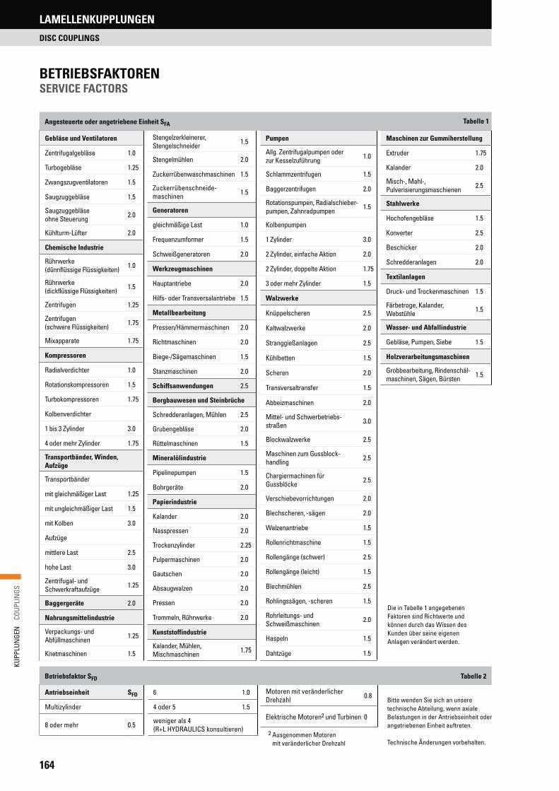
164
KUPP
LUN
GEN
C
OUPL
INGS
Antriebseinheit SFD
Multizylinder
8 oder mehr 0.5
Motoren mit veränderlicher Drehzahl 0.8
Elektrische Motoren2 und Turbinen 0
6 1.0
4 oder 5 1.5
weniger als 4 (R+L HYDRAULICS konsultieren)
Stengelzerkleinerer, Stengelschneider 1.5
Stengelmühlen 2.0
Zuckerrübenwaschmaschinen 1.5
Zuckerrübenschneide-maschinen 1.5
Generatoren
gleichmäßige Last 1.0
Frequenzumformer 1.5
Schweißgeneratoren 2.0
Werkzeugmaschinen
Hauptantriebe 2.0
Hilfs- oder Transversalantriebe 1.5
Metallbearbeitung
Pressen/Hämmermaschinen 2.0
Richtmaschinen 2.0
Biege-/Sägemaschinen 1.5
Stanzmaschinen 2.0
Schiffsanwendungen 2.5
Bergbauwesen und Steinbrüche
Schredderanlagen, Mühlen 2.5
Grubengebläse 2.0
Rüttelmaschinen 1.5
Mineralölindustrie
Pipelinepumpen 1.5
Bohrgeräte 2.0
Papierindustrie
Kalander 2.0
Nasspressen 2.0
Trockenzylinder 2.25
Pulpermaschinen 2.0
Gautschen 2.0
Absaugwalzen 2.0
Pressen 2.0
Trommeln, Rührwerke 2.0
Kunststoffindustrie
Kalander, Mühlen, Mischmaschinen 1.75
Gebläse und Ventilatoren
Zentrifugalgebläse 1.0
Turbogebläse 1.25
Zwangszugventilatoren 1.5
Saugzuggebläse 1.5
Saugzuggebläse ohne Steuerung 2.0
Kühlturm-Lüfter 2.0
Chemische Industrie
Rührwerke (dünnflüssige Flüssigkeiten) 1.0
Rührwerke (dickflüssige Flüssigkeiten) 1.5
Zentrifugen 1.25
Zentrifugen (schwere Flüssigkeiten) 1.75
Mixapparate 1.75
Kompressoren
Radialverdichter 1.0
Rotationskompressoren 1.5
Turbokompressoren 1.75
Kolbenverdichter
1 bis 3 Zylinder 3.0
4 oder mehr Zylinder 1.75
Transportbänder, Winden, Aufzüge
Transportbänder
mit gleichmäßiger Last 1.25
mit ungleichmäßiger Last 1.5
mit Kolben 3.0
Aufzüge
mittlere Last 2.5
hohe Last 3.0
Zentrifugal- und Schwerkraftaufzüge 1.25
Baggergeräte 2.0
Nahrungsmittelindustrie
Verpackungs- und Abfüllmaschinen 1.25
Knetmaschinen 1.5
Pumpen
Allg. Zentrifugalpumpen oderzur Kesselzuführung 1.0
Schlammzentrifugen 1.5
Baggerzentrifugen 2.0
Rotationspumpen, Radialschieber-pumpen, Zahnradpumpen 1.5
Kolbenpumpen
1 Zylinder 3.0
2 Zylinder, einfache Aktion 2.0
2 Zylinder, doppelte Aktion 1.75
3 oder mehr Zylinder 1.5
Walzwerke
Knüppelscheren 2.5
Kaltwalzwerke 2.0
Stranggießanlagen 2.5
Kühlbetten 1.5
Scheren 2.0
Transversaltransfer 1.5
Abbeizmaschinen 2.0
Mittel- und Schwerbetriebs-straßen 3.0
Blockwalzwerke 2.5
Maschinen zum Gussblock-handling 2.5
Chargiermachinen für Gussblöcke 2.5
Verschiebevorrichtungen 2.0
Blechscheren, -sägen 2.0
Walzenantriebe 1.5
Rollenrichtmaschine 1.5
Rollengänge (schwer) 2.5
Rollengänge (leicht) 1.5
Blechmühlen 2.5
Rohlingssägen, -scheren 1.5
Rohrleitungs- und Schweißmaschinen 2.0
Haspeln 1.5
Dahtzüge 1.5
Maschinen zur Gummiherstellung
Extruder 1.75
Kalander 2.0
Misch-, Mahl-, Pulverisierungsmaschienen 2.5
Stahlwerke
Hochofengebläse 1.5
Konverter 2.5
Beschicker 2.0
Schredderanlagen 2.0
Textilanlagen
Druck- und Trockenmaschinen 1.5
Färbetroge, Kalander, Webstühle 1.5
Wasser- und Abfallindustrie
Gebläse, Pumpen, Siebe 1.5
Holzverarbeitungsmaschinen
Grobbearbeitung, Rindenschäl-maschinen, Sägen, Bürsten 1.5
Angesteuerte oder angetriebene Einheit SFA
Betriebsfaktor SFD
Die in Tabelle 1 angegebenen Faktoren sind Richtwerte und können durch das Wissen des Kunden über seine eigenen Anlagen verändert werden.
Bitte wenden Sie sich an unsere technische Abteilung, wenn axiale Belastungen in der Antriebseinheit oder angetriebenen Einheit auftreten.
Technische Änderungen vorbehalten.2 Ausgenommen Motoren
mit veränderlicher Drehzahl
Tabelle 2
BETRIEBSFAKTORENSERVICE FACTORS
Tabelle 1
LAMELLENKUPPLUNGEN
DISC COUPLINGS
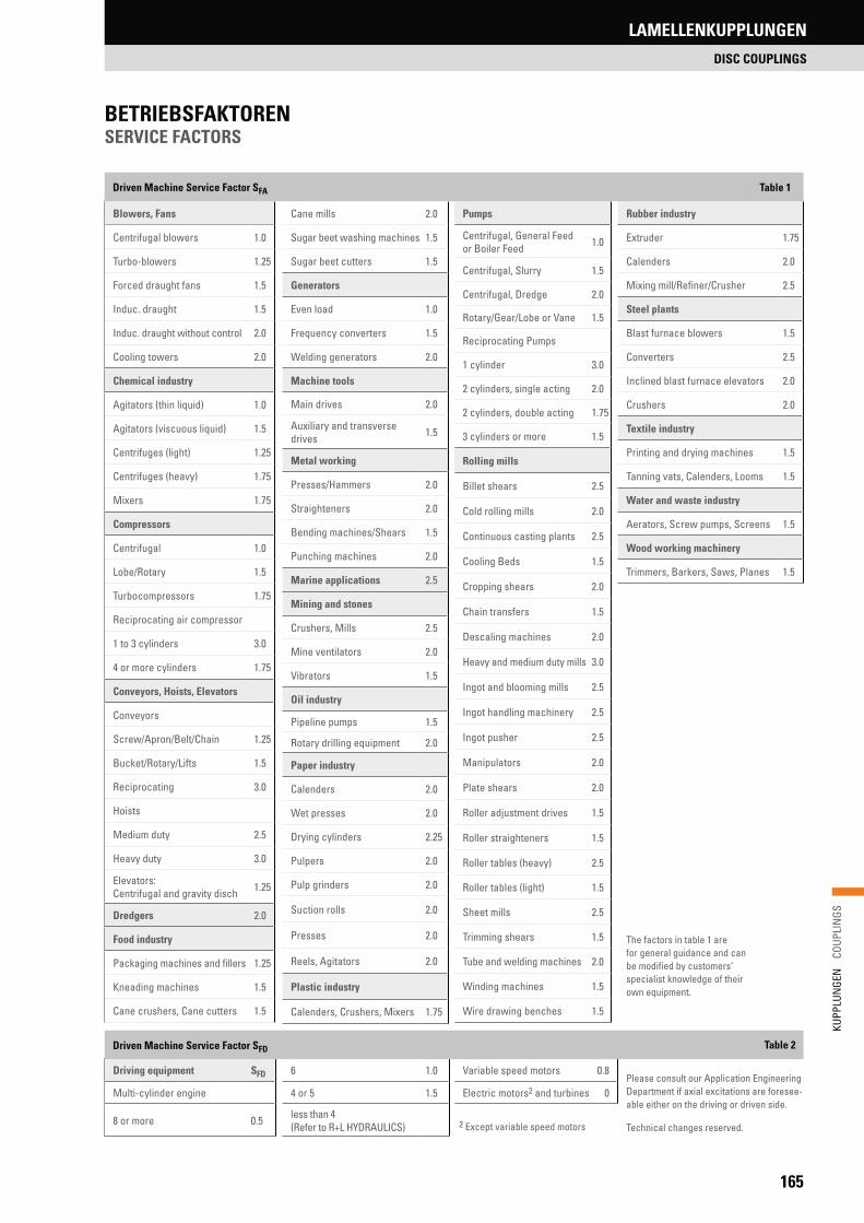
165
KUPP
LUN
GEN
C
OUPL
INGS
Driving equipment SFD
Multi-cylinder engine
8 or more 0.5
Variable speed motors 0.8
Electric motors2 and turbines 0
6 1.0
4 or 5 1.5
less than 4 (Refer to R+L HYDRAULICS)
Cane mills 2.0
Sugar beet washing machines 1.5
Sugar beet cutters 1.5
Generators
Even load 1.0
Frequency converters 1.5
Welding generators 2.0
Machine tools
Main drives 2.0
Auxiliary and transverse drives 1.5
Metal working
Presses/Hammers 2.0
Straighteners 2.0
Bending machines/Shears 1.5
Punching machines 2.0
Marine applications 2.5
Mining and stones
Crushers, Mills 2.5
Mine ventilators 2.0
Vibrators 1.5
Oil industry
Pipeline pumps 1.5
Rotary drilling equipment 2.0
Paper industry
Calenders 2.0
Wet presses 2.0
Drying cylinders 2.25
Pulpers 2.0
Pulp grinders 2.0
Suction rolls 2.0
Presses 2.0
Reels, Agitators 2.0
Plastic industry
Calenders, Crushers, Mixers 1.75
Blowers, Fans
Centrifugal blowers 1.0
Turbo-blowers 1.25
Forced draught fans 1.5
Induc. draught 1.5
Induc. draught without control 2.0
Cooling towers 2.0
Chemical industry
Agitators (thin liquid) 1.0
Agitators (viscuous liquid) 1.5
Centrifuges (light) 1.25
Centrifuges (heavy) 1.75
Mixers 1.75
Compressors
Centrifugal 1.0
Lobe/Rotary 1.5
Turbocompressors 1.75
Reciprocating air compressor
1 to 3 cylinders 3.0
4 or more cylinders 1.75
Conveyors, Hoists, Elevators
Conveyors
Screw/Apron/Belt/Chain 1.25
Bucket/Rotary/Lifts 1.5
Reciprocating 3.0
Hoists
Medium duty 2.5
Heavy duty 3.0
Elevators: Centrifugal and gravity disch 1.25
Dredgers 2.0
Food industry
Packaging machines and fillers 1.25
Kneading machines 1.5
Cane crushers, Cane cutters 1.5
Pumps
Centrifugal, General Feed or Boiler Feed 1.0
Centrifugal, Slurry 1.5
Centrifugal, Dredge 2.0
Rotary/Gear/Lobe or Vane 1.5
Reciprocating Pumps
1 cylinder 3.0
2 cylinders, single acting 2.0
2 cylinders, double acting 1.75
3 cylinders or more 1.5
Rolling mills
Billet shears 2.5
Cold rolling mills 2.0
Continuous casting plants 2.5
Cooling Beds 1.5
Cropping shears 2.0
Chain transfers 1.5
Descaling machines 2.0
Heavy and medium duty mills 3.0
Ingot and blooming mills 2.5
Ingot handling machinery 2.5
Ingot pusher 2.5
Manipulators 2.0
Plate shears 2.0
Roller adjustment drives 1.5
Roller straighteners 1.5
Roller tables (heavy) 2.5
Roller tables (light) 1.5
Sheet mills 2.5
Trimming shears 1.5
Tube and welding machines 2.0
Winding machines 1.5
Wire drawing benches 1.5
Rubber industry
Extruder 1.75
Calenders 2.0
Mixing mill/Refiner/Crusher 2.5
Steel plants
Blast furnace blowers 1.5
Converters 2.5
Inclined blast furnace elevators 2.0
Crushers 2.0
Textile industry
Printing and drying machines 1.5
Tanning vats, Calenders, Looms 1.5
Water and waste industry
Aerators, Screw pumps, Screens 1.5
Wood working machinery
Trimmers, Barkers, Saws, Planes 1.5
Driven Machine Service Factor SFA
Driven Machine Service Factor SFD
The factors in table 1 are for general guidance and can be modified by customers‘ specialist knowledge of their own equipment.
Please consult our Application Engineering Department if axial excitations are foresee-able either on the driving or driven side.
Technical changes reserved.2 Except variable speed motors
Table 1
Table 2
BETRIEBSFAKTORENSERVICE FACTORS
LAMELLENKUPPLUNGEN
DISC COUPLINGS

166
KUPP
LUN
GEN
C
OUPL
INGS
ANTRIEB EINES KOLBENKOMPRESSORSAntrieb: E-MotorLeistung: 160 kWDrehzahl: 1000 1/minWellendurchmesser: 95H7 x 170 mit Passfeder gem. DIN 6885/1Angetrieben: Kolbenkompressor mit drei Zylindern, mehrstufigWellendurchmesser: 92H7 mit Passfeder gem. DIN 6885/1Abstand zwischen den Wellenenden: ca. 178 mmVerlagerung zwischen den Wellenenden: radial Kr = 0,8 mm axial Ka = ±1,2 mm winklig Kw = ±1,5°
AUSWAHL DER GEEIGNETEN KUPPLUNGDa auch mit einem radialen Versatz zwischen den Wellenenden gerechnet wird, ist die Ausführung SU nicht geeignet, weil sie nur über ein Lamellen-paket verfügt und somit keine radialen Verlagerungen ausgleichen kann. Empfohlen wird daher die Ausführung SX oder DI (auf Anfrage erhältlich).
BESTIMMEN DER BETRIEBSFAKTORENAntrieb: E-Motor => gem. Tabelle 2: SFD = 0Angetrieben: Kolbenkompressor mit 3 Zylindern => gem. Tabelle 2: SFA = 3
BESTIMMEN DES ERFORDERLICHEN NENNMOMENTS
TKN erf =9.550 . 160 kW . 3
= 4.584 Nm1.000 1/min
AUSWAHL DER GEEIGNETEN BAUGRÖSSEAufgrund des erforderlichen Nennmoments wird die Baugröße SX 202-6 mit TKN = 4.600 Nm gewählt.
ÜBERPRÜFEN DES MAXIMALEN BOHRUNGSDURCHMESSERSDer maximale Bohrungsdurchmesser beträgt bei der Größe SX 202-6 d1/d2 = 90 mm. Daher muss die nächste Baugröße SX 228-6 gewählt werden.
ÜBERPRÜFEN DER ZULÄSSIGEN VERLAGERUNGENZulässige axiale Verlagerung:
Kazul = ±4,2 mm > Ka = ±1,2 mm
Zulässige winklige Verlagerung:
Ka= 0,29 < 0,5 = > gem. Diagramm 1 Kwzul = ±1° je Lamellenpaket
Kazul => Kwzul = ±2° für die gesamte Kupplung.
außerdem:
TK= 0,22 < 0,5 => gem. Diagramm 2 Kwzul = ±1° je Lamellenpaket
TKN => Kwzul = ±2° für die gesamte Kupplung.
=> Kwzul > Kw
Zulässige radiale Verlagerung:
Die Standardausführung der SX 228-6 ist geeignet für einen Abstand von S = 178 mm zwischen den Wellenenden. Entsprechend ergibt sich ein Abstand von Z = 140 mm zwischen den Lamellenpaketen. Somit gilt für die maximal zulässige radiale Verlagerung:
Krzul = tan1° × 140 mm = 2,4 mm > Kr
Generell wird empfohlen, bei der Montage darauf zu achten, dass die tatsächlichen Verlagerungswerte maximal 20 % der zulässigen Werte betragen. Dadurch hat die Kupplung die Möglichkeit, zusätzliche Verla-gerungen, die im Laufe des Betriebs durch Verschleiß und Setzung auf-treten können, auszugleichen.
DRIVE OF A RECIPROCATING AIR COMPRESSORDriving Machine: electric motorNominal Power: 160 kWSpeed: 1000 1/minShaft Diameter: 95H7 x 170 with key according DIN 6885/1Driven Machine: three cylinder multi stage reciprocating air compressorShaft Diameter: 92H7 with key according DIN 6885/1Distance between the shaft ends: roughly 178 mmMisalignment between the shaft ends: parallel Kr = 0,8 mm axial Ka = ±1,2 mm angular Kw = ±1,5°
DETERMINE THE TYPE OF COUPLINGSince the SU Type coupling only supports a single flex plane, it can only accommodate angular and axial misalignment, but not parallel misalign-ment. The next choice would be to look at an SX or DI Type coupling (available on request). The 6 bolt SX Type will accommodate both parallel misalignment and the defined shaft separation.
DETERMINE THE SERVICE FACTORSDriving Machine: electric motor => according Table 2: SFD = 0Driven Machine: three cylinder multi stage reciprocating air compressor => according Table 2: SFA = 3
CALCULATE THE SELECTION TORQUE
TKN erf =9.550 . 160 kW . 3
= 4.584 Nm1.000 1/min
SELECT THE SUITABLE SIZEBased on the selection torque calculated in step 3 the size SX 202-6 with a nominal torque of TKN = 4.600 Nm will be selected.
DOUBLECHECK THE MAXIMUM BORE DIAMETERThe maximum bore diameter which is available for size 202-6 is d1/d2 = 90 mm. Therefore the next larger size SX 228-6 has to be used.
DOUBLECHECK THE PERMISSIBLE MISALIGNMENTPermissible axiale misalignment:
Kazul = ±4,2 mm > Ka = ±1,2 mm
Permissible angular misalignment:
Ka= 0,29 < 0,5 = > according Diagram 1 Kwzul = ±1° per disc pack
Kazul => Kwzul = ±2° for two disc pack.
also:
TK= 0,22 < 0,5 => according Diagram 2 Kwzul = ±1° per disc pack
TKN => Kwzul = ±2° for two disc pack.
=> Kwzul > Kw
Permissible radial misalignment:
The SX 228-6 will support a distance of S = 178 mm between the shaft ends. The means a distance of Z = 140 mm between disc packs. So the permissible parallel misalignment will be
Krzul = tan1° × 140 mm = 2,4 mm > Kr
It is always recommended to try to install the coupling at roughly 20 % of the allowable misalignment. For this coupling the installer should try to achieve better than 0.020 parallel misalignment at the time of installation. This will allow for the additional misalignment that will occur as the result of equipment settle and general equipment wear.
AUSLEGUNGSBEISPIELSAMPLE APPLICATION
LAMELLENKUPPLUNGEN
DISC COUPLINGS

167
KUPP
LUN
GEN
C
OUPL
INGS
BaugrößeSize
Nennmoment Nominal torque
[Nm]
Max. MomentPeak torque
[Nm]
Drehfedersteife 1) Torsional stiffness 1)
x 106 [Nm/rad]
Zulässiger axialer Versatz 2) Permissible axial misalignment 2)
± ka [mm]
Zulässiger Winkelversatz 3),4) Permissible angular misalignment 3),4)
[°]
90-6 240 480 0.3 1.5 1.5
110-6 575 150 0.4 2.1 1.5
132-6 1100 2200 0.5 2.6 1.5
158-6 2000 4000 0.7 3.1 1.5
185-6 3300 6600 1.3 3.7 1.5
202-6 4600 9200 1.5 3.8 1.0
228-6 7000 14000 2.6 4.2 1.0
255-6 10200 20400 4.7 4.7 1.0
278-6 14200 28400 7.1 5.2 1.0
302-6 20000 40000 9.5 5.7 1.0
325-6 25000 50000 13.0 6.5 1.0
345-6 31000 62000 17.0 6.9 1.0
380-6 42300 84600 22.0 7.6 1.0
410-6 57100 114200 28.0 8.2 1.0
440-6 73500 147000 35.0 8.8 1.0
278-8 20000 40000 9.5 3.7 0.5
302-8 30000 60000 14.9 4.0 0.5
325-8 37000 74000 20.4 4.3 0.5
345-8 46000 92000 25.0 4.6 0.5
380-8 63000 126000 34.0 5.0 0.5
410-8 86000 172000 40.0 5.4 0.5
440-8 110000 220000 49.0 5.8 0.5
TECHNISCHE DATEN TECHNICAL DATA DISC PACKETS
1) Drehsteifigkeit des Lamellenpaketes Torsional stiffness is provided for one disc pack2) Zulässiger axialer Versatz für eine Kupplung mit zwei Lamellenpaketen Axial misaligment is provided for couplings with two disc packs3) Zulässiger Winkelversatz bezieht sich auf ein einzelnes Lamellenpake Angular misalignent is provided per single disc pack4) Siehe auch Abbildung 1 + 2, Seite 162 See page 162 figure 1 + 2 for additional informaiton regarding misalignment
LAMELLENPAKETEDISC PACKETS
LAMELLENKUPPLUNGEN
DISC COUPLINGS

168
KUPP
LUN
GEN
C
OUPL
INGS
LAMELLENKUPPLUNGEN
DISC COUPLINGS
Bau-größeSize
Nenn-moment Nominal torque
TKN
Max. Moment
Peak torque
TKNmax
Maximale DrehzahlMax. speed
Gewicht 4) Weight 4)
Massen-trägheits-moment 5) Moment
of inertia 5)
Zulässiger axialer
Versatz 6) Permissible
axial misalignment 6)
± kazul
Zulässiger Winkelversatz 7),8),9)
Permissible angular misalign-
ment 7),8),9)
± kwzul
d1/d2
Max. Bohrungs-
durchmesser 3) Max. bore 3)
L P L1/L2 A B
ohne wuchten 1)
without blancing 1)
mit wuchten 2)
with blancing 2)
[Nm] [Nm] [1/min] [1/min] [kg] [kgm2] [mm] [°] [mm] [mm] [mm] [mm] [mm] [mm]
90-6 240 480 9100 22700 1.4 0.001 0.75 1.5 38 88 7.5 40 90 58
110-6 575 1150 7200 18000 2.3 0.001 1.00 1.5 46 108 8.4 50 110 65
132-6 1100 2200 5840 14600 3.8 0.001 1.30 1.5 60 128 8.4 60 132 84
158-6 2000 4000 4920 12300 6.4 0.001 1.50 1.5 70 151 11.2 70 158 98
185-6 3300 6600 4200 10500 9.9 0.001 1.80 1.5 80 174 14.0 80 185 112
202-6 4600 9200 3840 9600 13.5 0.001 1.90 1.0 90 196 15.5 90 202 125
228-6 7000 14000 3400 8500 19.0 0.001 2.10 1.0 100 218 17.5 100 228 140
255-6 10200 20400 3080 7700 29.0 0.001 2.30 1.0 110 251 20.5 115 255 155
278-6 14200 28400 2800 7000 37.0 0.001 2.60 1.0 124 271 21.2 125 278 174
302-6 20000 40.000 2560 6400 49.0 0.001 2.80 1.0 135 294 24.4 135 302 190
325-6 25000 50.000 2400 6000 60.5 0.001 3.20 1.0 145 316 26.0 145 325 205
345-6 31000 62.000 2200 5500 73.0 0.001 3.40 1.0 155 338 28.2 155 345 217
380-6 42300 84.600 2040 5100 96.0 0.001 3.80 1.0 170 372 32.0 170 380 238
410-6 57100 114200 1880 4700 124.0 0.001 4.10 1.0 180 403 33.2 185 410 255
440-6 73500 147000 1740 4350 151.0 0.001 4.40 1.0 195 426 36.4 195 440 273
AUSFÜHRUNG SUSU TYPE
ABMESSUNGENDIMENSIONS
1) Ungewuchtet; Erfüllt die Andorderungen gem. AGMA 9000-C90 Klasse 9 Balanced as manufactured; Meets the requirements according AGMA 9000-C90 Class 9. 2) Gewuchtet; Erfüllt die Anforderungen von AGMA 9000-C90 Klasse 10 Balanced; Meets the requirements according AGMA 9000-C90 Class 10. 3) Der maximale Bohrungsdurchmesser bezieht sich auf zylindrische oder konische Bohrungen mit Passfedernuten. Bei Profilverzahnungen wenden Sie sich bitte an unsere
technische Abteilung. The maximum bores shown are for cylindrical or taper shafts with keys. For splines and other bore types, contact R+L HYDRAULICS Technical Support.4) Gewicht bezieht sich auf eine komplette Kupplung mit maximalem Bohrungsdurchmesser Weight is given for a complete coupling with maximum bores. 5) Wert für die Kupplung bei maximalem d1 und d2 und GD2 = 4J Moment of inertia is given for a complete coupling with maximum bores and GD2 = 4J. 6) Zulässiger axialer Versatz für eine Kupplung mit einem Lamellenpaket Axial misaligment is provided for coupling with one disc pack. 7) Zulässiger Winkelversatz bezieht sich auf ein einzelnes Lamellenpaket Angular misalignent is provided per single disc pack. 8) Siehe auch Abbildung 1 + 2, Seite 162 See page 162 figure 1 + 2 for additional informaiton regarding misalignment9) Die Ausführung SU lässt keinen parallelen Versatz zu There is no parallel misalginment for the SU Type.
LamellenpaketDisc pack
NabeHub
L
P
Ø d1
L1 L2
Ø d2
Ø B
Ø A

169
KUPP
LUN
GEN
C
OUPL
INGS
LAMELLENKUPPLUNGEN
DISC COUPLINGS
Bau-größeSize
Nenn-moment Nominal torque
TKN
Max. Moment
Peak torque
TKNmax
Maximale DrehzahlMax. Speed
Gewicht 4) Weight 4)
Massen-trägheits-moment 5) Moment of
Inertia 5)
Zulässiger axialer
Versatz 6) Permissible
axial misalign-
ment 6)
± ka
Zulässiger Winkel-
versatz 7),8) Permissible
angular misalign-ment 7),8)
± kW
d1/d2
Max. Bohrungs-
durch-messer 3)
Max. bore 3)
L Z P L1/L2 S 9) A B
ohne wuchten 1)
without blancing 1)
mit wuchten 2)
with blancing 2)
[Nm] [Nm] [1/min] [1/min] [kg] [kgm2] [mm] [°] [mm] [mm] [mm] [mm] [mm] [mm] [mm] [mm]
90-6 240 480 9100 22700 2.1 0.002 1.5 1.5 38 134 45 7.5 40 60 90 58
110-6 575 1150 7200 18000 2.9 0.004 2.1 1.5 46 189 72 8.4 50 89 110 65
132-6 1100 2200 5840 14600 5.5 0.012 2.6 1.5 60 228 91 8.4 60 108 132 84
158-6 2000 4000 4920 12300 8.6 0.025 3.1 1.5 70 264 102 11.2 70 124 158 98
185-6 3300 6600 4200 10500 15.0 0.063 3.7 1.5 80 300 112 14.0 80 140 185 112
202-6 4600 9200 3840 9600 21.0 0.110 3.8 1.0 90 339 128 15.5 90 159 202 125
228-6 7000 14000 3400 8500 30.0 0.200 4.2 1.0 100 375 140 17.5 100 175 228 140
255-6 10200 20400 3080 7700 40.0 0.320 4.7 1.0 110 427 156 20.5 115 197 255 155
278-6 14200 28400 2800 7000 57.0 0.560 5.2 1.0 124 469 177 21.2 125 219 278 174
302-6 20000 40000 2560 6400 74.0 0.860 5.7 1.0 135 505 186 24.4 135 235 302 190
325-6 25000 50000 2400 6000 89.0 1.170 6.5 1.0 145 544 202 26.0 145 254 325 205
345-6 31000 62000 2200 5500 109.0 1.630 6.9 1.0 155 580 214 28.2 155 270 345 217
380-6 42300 84600 2040 5100 146.0 2.640 7.6 1.0 170 637 233 32.0 170 297 380 238
410-6 57100 114200 1880 4700 190.0 4.040 8.2 1.0 180 690 254 33.2 185 321 410 255
440-6 73500 147000 1740 4350 224.0 5.450 8.8 1.0 195 725 262 36.4 195 335 440 273
AUSFÜHRUNG SX-6SX-6 TYPE
1) Ungewuchtet; Erfüllt die Andorderungen gem. AGMA 9000-C90 Klasse 9. Balanced as manufactured; Meets the requirements according AGMA 9000-C90 Class 9.2) Gewuchtet; Erfüllt die Anforderungen von AGMA 9000-C90 Klasse 10. Balanced; Meets the requirements according AGMA 9000-C90 Class 10. 3) Der maximale Bohrungsdurchmesser bezieht sich auf zylindrische oder konische Bohrungen mit Passfedernuten. Bei Profilverzahnungen oder anderen Verbindungen
wenden Sie sich bitte an unsere technische Abteilung. The maximum bores shown are for cylindrical or taper shafts with keys. For splines and other bore types, contact R+L HYDRAULICS Technical Support.
4) Gewicht bezieht sich auf eine komplette Kupplung mit maximalem Bohrungsdurchmesser und minimalem Abstand zwischen den Wellenenden. Weight is given for a complete coupling with minimum BSE and maximum bores.
5) Wert für die Kupplung bei minimalem S und maximalem d1 und d2 und GD2 = 4J Moment of inertia is given for a complete coupling with minimum S and maximum bores and GD2 = 4J.
6) Zulässiger axialer Versatz für eine Kupplung mit zwei Lamellenpaketen Axial misaligment is provided for two disc packs 7) Zulässiger Winkelversatz bezieht sich auf ein einzelnes Lamellenpaket Angular misalignent is provided per single disc pack8) Siehe auch Abbildung 1 + 2, Seite 162 See page 162 figure 1 + 2 for additional informaiton regarding misalignment.9) Entspricht dem Abstand zwischen den Wellenenden. Auf Anfrage vom Standard abweichende Abstände möglich / Distance between the shaft ends. Other then the standard
available on request.
ABMESSUNGENDIMENSIONS
LamellenpaketDisc pack
NabeHub
ZwischenstückSpacer
LZ P
S
L1 L2
Ø A
Ø d1
Ø d2

170
KUPP
LUN
GEN
C
OUPL
INGS
LAMELLENKUPPLUNGEN
DISC COUPLINGS
AUSFÜHRUNG SX-8SX-8 TYPE
Bau-größeSize
Nenn-moment Nominal torque
TKN
Max. Moment
Peak torque
TKNmax
Maximale DrehzahlMax. Speed
Gewicht 4) Weight 4)
Massen-trägheits-moment 5) Moment
of inertia 5)
Zulässiger axialer
Versatz 6) Permissible
Axial misalign-ment 6)
± kazul
Zulässiger Winkel-
versatz 7,8) Permissible
Angular misalign-ment 7,8)
± kwzul
d1/d2
Max. Bohrungs-
durch-messer 3)
Max. bore 3)
L Z P L1/L2 S 9) A B
ohne wuchten 1)
without blancing 1)
mit wuchten 2)
with blancing 2)
[Nm] [Nm] [1/min] [1/min] [kg] [kgm2] [mm] [°] [mm] [mm] [mm] [mm] [mm] [mm] [mm] [mm]
278-8 20000 40000 2800 7000 59 0.573 3.7 0.5 124 469 177 21.2 125 219 278 174
302-8 30000 60000 2560 6400 77 0.878 4.0 0.5 135 505 186 24.4 135 235 302 190
325-8 37000 74000 2400 6000 92 1.199 4.3 0.5 145 544 202 26.0 145 254 325 205
345-8 46000 92000 2200 5500 112 1.660 4.6 0.5 155 580 214 28.2 155 270 345 217
380-8 63000 126000 2040 5100 150 2.715 5.0 0.5 170 637 233 32.0 170 297 380 238
410-8 86000 172000 1880 4700 195 4.110 5.4 0.5 180 690 254 33.2 185 321 410 255
440-8 110000 220000 1740 4350 230 5.540 5.8 0.5 195 725 262 36.4 195 335 440 273
1) Ungewuchtet; Erfüllt die Andorderungen gem. AGMA 9000-C90 Klasse 9 Balanced as manufactured; Meets the requirements according AGMA 9000-C90 Class 9.2) Gewuchtet; Erfüllt die Anforderungen von AGMA 9000-C90 Klasse 10 Balanced; Meets the requirements according AGMA 9000-C90 Class 10. 3) Der maximale Bohrungsdurchmesser bezieht sich auf zylindrische oder konische Bohrungen mit Passfedernuten. Bei Profilverzahnungen oder anderen Verbindungen
wenden Sie sich bitte an unsere technische Abteilung. The maximum bores shown are for cylindrical or taper shafts with keys. For splines and other bore types, contact R+L HYDRAULICS Technical Support.
4) Gewicht bezieht sich auf eine komplette Kupplung mit maximalem Bohrungsdurchmesser und minimalem Abstand zwischen den Wellenenden. Weight is given for a complete coupling with minimum BSE and maximum bores.
5) Wert für die Kupplung bei minimalem S und maximalem d1 und d2 und GD2 = 4J Moment of inertia is given for a complete coupling with minimum S and maximum bores and GD2 = 4J.
6) Zulässiger axialer Versatz für eine Kupplung mit zwei Lamellenpaketen Axial misaligment is provided for two disc packs. 7) Zulässiger Winkelversatz bezieht sich auf ein einzelnes Lamellenpaket Angular misalignent is provided per single disc pack. 8) Siehe auch Abbildung 1 + 2, Seite 162 See page 162 figure 1 + 2 for additional informaiton regarding misalignment9) Entspricht dem Abstand zwischen den Wellenenden. Auf Anfrage vom Standard abweichende Abstände möglich. Distance between the shaft ends. Other then the standard
available on request.
LamellenpaketDisc pack
NabeHub
ZwischenstückSpacer
LZ P
S
L1 L2
Ø A
Ø d1
Ø d2
ABMESSUNGENDIMENSIONS
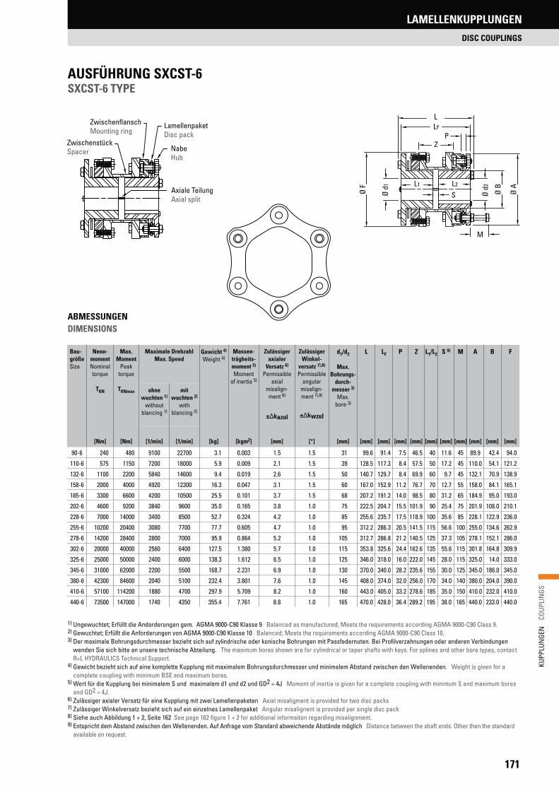
171
KUPP
LUN
GEN
C
OUPL
INGS
LAMELLENKUPPLUNGEN
DISC COUPLINGS
Bau-größeSize
Nenn-momentNominaltorque
TKN
Max. Moment
Peak torque
TKNmax
Maximale DrehzahlMax. Speed
Gewicht 4) Weight 4)
Massen-trägheits-moment 5)
Moment of inertia 5)
Zulässiger axialer
Versatz 6)
Permissible axial
misalign-ment 6)
± kazul
Zulässiger Winkel-
versatz 7),8)
Permissible angular
misalign-ment 7),8)
± kwzul
d1/d2
Max. Bohrungs-
durch-messer 3)
Max. bore 3)
L LF P Z L1/L2 S 9) M A B F
ohne wuchten 1)
without blancing 1)
mit wuchten 2)
with blancing 2)
[Nm] [Nm] [1/min] [1/min] [kg] [kgm2] [mm] [°] [mm] [mm] [mm] [mm] [mm] [mm] [mm] [mm] [mm] [mm] [mm]
90-6 240 480 9100 22700 3.1 0.003 1.5 1.5 31 99.6 91.4 7.5 46.5 40 11.6 45 89.9 42.4 94.0
110-6 575 1150 7200 18000 5.9 0.009 2.1 1.5 39 128.5 117.3 8.4 57.5 50 17.2 45 110.0 54.1 121.2
132-6 1100 2200 5840 14600 9.4 0.019 2.6 1.5 50 140.7 129.7 8.4 69.9 60 9.7 45 132.1 70.9 138.9
158-6 2000 4000 4920 12300 16.3 0.047 3.1 1.5 60 167.0 152.9 11.2 76.7 70 12.7 55 158.0 84.1 165.1
185-6 3300 6600 4200 10500 25.5 0.101 3.7 1.5 68 207.2 191.2 14.0 98.5 80 31.2 65 184.9 95.0 193.0
202-6 4600 9200 3840 9600 35.0 0.165 3.8 1.0 75 222.5 204.7 15.5 101.9 90 25.4 75 201.9 108.0 210.1
228-6 7000 14000 3400 8500 52.7 0.324 4.2 1.0 85 255.6 235.7 17.5 118.9 100 35.6 85 228.1 122.9 236.0
255-6 10200 20400 3080 7700 77.7 0.605 4.7 1.0 95 312.2 286.3 20.5 141.5 115 56.6 100 255.0 134.6 262.9
278-6 14200 28400 2800 7000 95.9 0.864 5.2 1.0 105 312.7 286.8 21.2 140.5 125 37.3 105 278.1 152.1 286.0
302-6 20000 40000 2560 6400 127.5 1.380 5.7 1.0 115 353.8 325.6 24.4 162.6 135 55.6 115 301.8 164.8 309.9
325-6 25000 50000 2400 6000 138.3 1.612 6.5 1.0 125 346.0 318.0 16.0 222.0 145 28.0 115 325.0 14.0 333.0
345-6 31000 62000 2200 5500 168.7 2.231 6.9 1.0 130 370.0 340.0 28.2 235.6 155 30.0 125 345.0 186.0 345.0
380-6 42300 84600 2040 5100 232.4 3.801 7.6 1.0 145 408.0 374.0 32.0 256.0 170 34.0 140 380.0 204.0 390.0
410-6 57100 114200 1880 4700 297.9 5.709 8.2 1.0 160 443.0 405.0 33.2 278.6 185 35.0 150 410.0 232.0 410.0
440-6 73500 147000 1740 4350 355.4 7.761 8.8 1.0 165 470.0 428.0 36.4 289.2 195 38.0 165 440.0 233.0 440.0
AUSFÜHRUNG SXCST-6SXCST-6 TYPE
1) Ungewuchtet; Erfüllt die Andorderungen gem. AGMA 9000-C90 Klasse 9 Balanced as manufactured; Meets the requirements according AGMA 9000-C90 Class 9.2) Gewuchtet; Erfüllt die Anforderungen von AGMA 9000-C90 Klasse 10 Balanced; Meets the requirements according AGMA 9000-C90 Class 10. 3) Der maximale Bohrungsdurchmesser bezieht sich auf zylindrische oder konische Bohrungen mit Passfedernuten. Bei Profilverzahnungen oder anderen Verbindungen
wenden Sie sich bitte an unsere technische Abteilung. The maximum bores shown are for cylindrical or taper shafts with keys. For splines and other bore types, contact R+L HYDRAULICS Technical Support.
4) Gewicht bezieht sich auf eine komplette Kupplung mit maximalem Bohrungsdurchmesser und minimalem Abstand zwischen den Wellenenden. Weight is given for a complete coupling with minimum BSE and maximum bores.
5) Wert für die Kupplung bei minimalem S und maximalem d1 und d2 und GD2 = 4J Moment of inertia is given for a complete coupling with minimum S and maximum bores and GD2 = 4J.
6) Zulässiger axialer Versatz für eine Kupplung mit zwei Lamellenpaketen Axial misaligment is provided for two disc packs 7) Zulässiger Winkelversatz bezieht sich auf ein einzelnes Lamellenpaket Angular misalignent is provided per single disc pack 8) Siehe auch Abbildung 1 + 2, Seite 162 See page 162 figure 1 + 2 for additional informaiton regarding misalignment.9) Entspricht dem Abstand zwischen den Wellenenden. Auf Anfrage vom Standard abweichende Abstände möglich Distance between the shaft ends. Other then the standard
available on request.
ABMESSUNGENDIMENSIONS
LamellenpaketDisc pack
NabeHub
ZwischenstückSpacer
ZwischenflanschMounting ring
Axiale TeilungAxial split
LLF
PZ
M
Ø d1
Ø d2 Ø B
Ø A
Ø F
SL1 L2
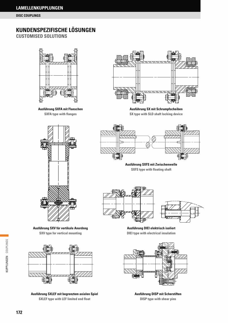
172
KUPP
LUN
GEN
C
OUPL
INGS
LAMELLENKUPPLUNGEN
DISC COUPLINGS
KUNDENSPEZIFISCHE LÖSUNGENCUSTOMISED SOLUTIONS
Ausführung SXFA mit Flanschen SXFA type with flanges
Ausführung SXV für vertikale Anordnng SXV type for vertical mounting
Ausführung DISP mit ScherstiftenDISP type with shear pins
Ausführung SXLEF mit begrenztem axialen SpielSXLEF type with LEF limited end float
Ausführung DIEI elektrisch isoliertDIEI type with electrical insulation
Ausführung SX mit Schrumpfscheiben SX type with SLD shaft locking device
Ausführung SXFS mit ZwischenwelleSXFS type with floating shaft

173
KUPP
LUN
GEN
C
OUPL
INGS
KUPPLUNGEN FÜR DEN ATEX-BEREICH
COUPLINGS FOR ATEX ZONES
KUPPLUNGEN FÜR DEN ATEX-BEREICHCOUPLINGS FOR ATEX ZONES
Die derzeit geltende ATEX-Richtlinie 2014/34/EU stellt weitreichende Anforderungen an Anlagen und deren Komponenten für den Einsatz in explosionsgefährdeten Bereichen.Als Spezialist in der Fluid- und Antriebstechnik, bietet Ihnen das Portfolio der R+L HYDRAULICS zahlreiche ATEX-konforme Lösungen für Ihre An-wendungen in allen Branchen.
The currently valid ATEX guideline 2014/24/EU requires extensive de-mands on systems and their components for being used in explosive areas. As a specialist in fluid and power transmission the portfolio from R+L HYDRAULICS offers you numerous ATEX compliant solutions for your applications in all sectors.
ProdukteProducts
SPIDEX® DENTEX® HercuFlex Lamellenkupplungen Disc couplings
Gerätegruppe I
Bis SPIDEX® 75Up to SPIDEX® 75(Keine Alu-Naben)(No aluminium hubs)
I M2 X
Serie B bis B65Series B up to B65Serie FL bis Ø 220 mmSeries FL up to Ø 6 ½”
I M2 X
Alle GrößenAll sizes
I M2 c X
Alle GrößenAll sizes
I M2 c
Gerätegruppe II
Bis SPIDEX® 65Up to SPIDEX® 65
II 2GD IIC TX
Serie B bis B65 (IIA, IIB, IIC)Series B up to B65 (IIA, IIB, IIC)Serie FL bis Ø 96 mm (nur IIC)Series FL up to Ø 3 ¾” (only IIC)
II 2GD IIC TX
Alle GrößenAll sizes
-30 °C Ta +65 °C, +80 °C, +90 °C
II 2G cIIC T6, T5, T4 X
Alle GrößenAll sizes
II 2GD c 135 °C (T4)
Bis SPIDEX® 125Up to SPIDEX® 125
II 2GD IIB TX
Serie FL ab Ø 125 mm bis Ø 220 mmSeries FL from Ø 5” up to Ø 6 ½”
II 2GD IIB TX
Alle GrößenAll sizes
-30 °C Ta +90 °C
II 2D c T 110 °C
Alle GrößenAll sizes
II 2GD c 100 °C (T5)
Bis SPIDEX® 140Up to SPIDEX® 140
II 2D 3G TX
Serie B, B3R, B4R und FLSeries B, B3R, B4R and FL
II 2GD IIB TX

R+L HYDRAULICS GmbHFriedrichstraße 6D-58791 Werdohl Phone: +49 2392 509-0
© R+L HYDRAULICS GmbH, 06/2018
DER DIREKTE DRAHT ZU R+L HYDRAULICS
Durchwahl für Deutschland: +49 2392 509-155
E-Mail Deutschland: [email protected]
Durchwahl Export: +49 2392 509-130
E-Mail Export: [email protected]
THE DIRECT CONTACT TO R+L HYDRAULICS
Direct dialling for Germany: +49 2392 509-155
E-Mail Germany: [email protected]
Direct dialling export: +49 2392 509-130
E-Mail export: [email protected]


![Catalogue technique MG05 - Poclain Hydraulics€¦ · CleanStart system / Hydraulic starter POCLAIN HYDRAULICS ... [5000] P Inlet from pump G3 ... (Hirschmann) 4 P5 Hydraulic connections](https://img.pdfslide.net/doc/110x75/5b399b777f8b9a5a178e8fb3/catalogue-technique-mg05-poclain-cleanstart-system-hydraulic-starter-poclain.jpg)