Embed Size (px)
Citation preview

BL20
Phone: 800.894.0412 - Fax: 888.723.4773 - Web: www.clrwtr.com - Email: [email protected]

Creating Potential Groups
Both bus refreshing modules and power feeding modules may be used to create a potential group. The base modulecreates the possible isolation of the potential group on the left-hand side of the respective power distribution module.
It is not permitted for modules with 24 VDC and with 120/230 VAC field supply to be used in a joint potential group.Therefore, when using digital input modules for 120/230 VAC, the power feeding module BL20-PF-120/230VAC-D is to beused to create a special potential group.
C-rail (Cross Connection)
C-rails run through all I/O base modules. The C-rail for base modules for power distribution is mechanically separated; thuspotentially isolating the adjoining supply groups.
Access to the C-rail
Access to the C-rail is made via base modules with a C designation (i.e. BL20-S4T-SBCS). The corresponding connectionlevel is indicated by a thick black line on all base modules for BL20 I/O modules. For base modules for power distribution,the black line is only above the connection “24" to indicate that the C-rail is separated from the adjoining potential group toits left.
It is permitted to load the C-rail with a maximum of 24 V; never with 120/230 VAC.
Using the C-rail with Relay Modules
The C-rail may be used to supply a common voltage when relay modules are used. To accomplish this, the load voltage (24VDC) is connected to a power distribution module and the base module BL20-P4x-SBBC with either tension clamp or screwconnections.
If the C-rail is used for the joint supply of voltage to relay modules, there must be a power distribution module used for thepotential isolation of the BL20 modules. The C-rail may still be used as protective earth (PE) once the potential isolation hasbeen made.
Using the C-rail as a Protective Earth
A C-rail may be used as a protective earth (PE), where the PE connection for each power distribution modules must beconnected to the mounting rail via an additional PE terminal, which is available as an accessory.
Phone: 800.894.0412 - Fax: 888.723.4773 - Web: www.clrwtr.com - Email: [email protected]
BL20
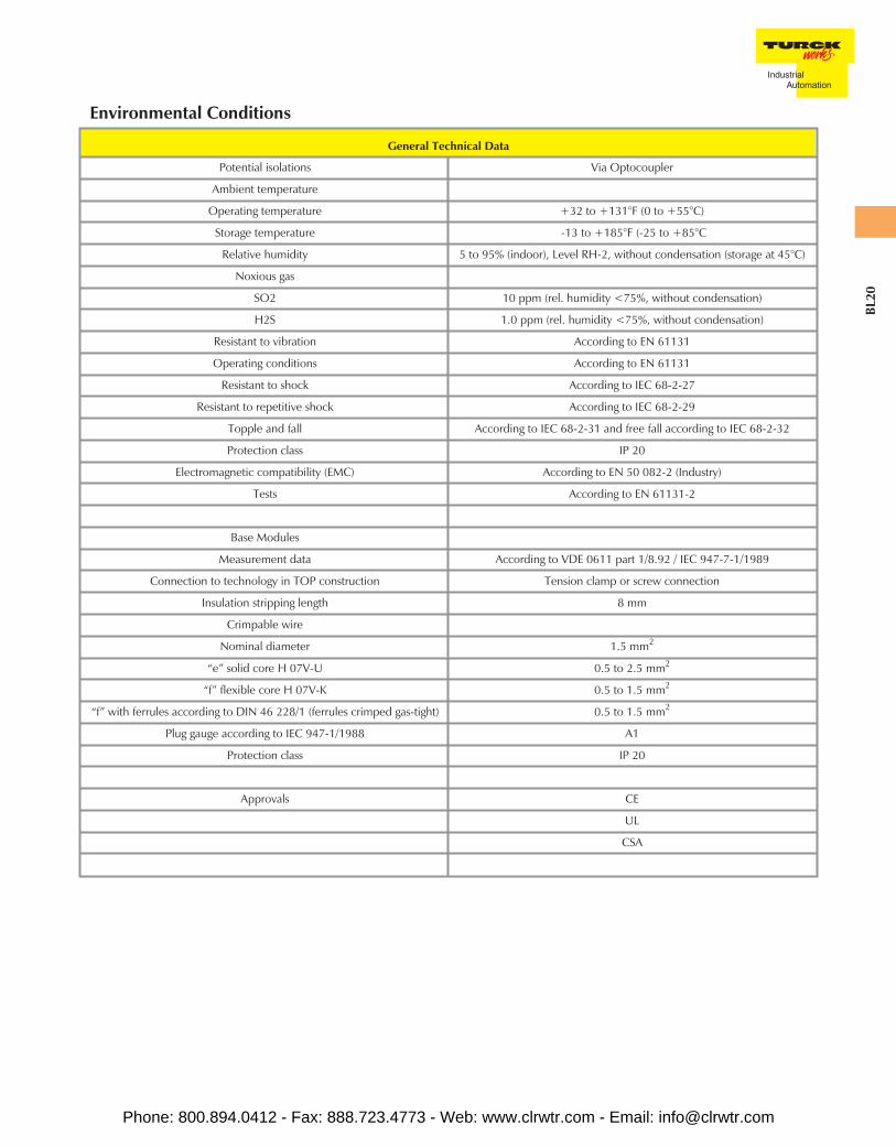
General Technical Data
Potential isolations Via Optocoupler
Ambient temperature
Operating temperature +32 to +131°F (0 to +55°C)
Storage temperature -13 to +185°F (-25 to +85°C
Relative humidity 5 to 95% (indoor), Level RH-2, without condensation (storage at 45°C)
Noxious gas
SO2 10 ppm (rel. humidity <75%, without condensation)
H2S 1.0 ppm (rel. humidity <75%, without condensation)
Resistant to vibration According to EN 61131
Operating conditions According to EN 61131
Resistant to shock According to IEC 68-2-27
Resistant to repetitive shock According to IEC 68-2-29
Topple and fall According to IEC 68-2-31 and free fall according to IEC 68-2-32
Protection class IP 20
Electromagnetic compatibility (EMC) According to EN 50 082-2 (Industry)
Tests According to EN 61131-2
Base Modules
Measurement data According to VDE 0611 part 1/8.92 / IEC 947-7-1/1989
Connection to technology in TOP construction Tension clamp or screw connection
Insulation stripping length 8 mm
Crimpable wire
Nominal diameter 1.5 mm2
“e” solid core H 07V-U 0.5 to 2.5 mm2
“f” flexible core H 07V-K 0.5 to 1.5 mm2
“f” with ferrules according to DIN 46 228/1 (ferrules crimped gas-tight) 0.5 to 1.5 mm2
Plug gauge according to IEC 947-1/1988 A1
Protection class IP 20
Approvals CE
UL
CSA
Environmental Conditions
Phone: 800.894.0412 - Fax: 888.723.4773 - Web: www.clrwtr.com - Email: [email protected]

BL20-GWBR-DNET
DeviceNet Gateway • Modular I/O• Fieldbus Independent Configuration
• IP 20 Protection• Various I/O Styles
Electrical• Operating Current: <250 mA from BR power supply• Supply Current: <10 A to I/O (from UL)
<1.5 A to backplane (from USYS)
Mechanical• Operating Temperature: 0 to +55°C (+32 to +131°F)• Protection: IP 20• Vibration: 1 g @ 5-100 Hz
Material• Housing: PC-V0 (Lexan)
Diagnostics (Logical)• Diagnostic information available through the DeviceNet I/O map
Diagnostics (Physical)• LEDs to indicate status of DeviceNet and Module Bus communication
1 = USYS
2 = GndSYS
3 = UL
4 = GndL
DeviceNet Connector
Power Connection
Phone: 800.894.0412 - Fax: 888.723.4773 - Web: www.clrwtr.com - Email: [email protected]

BL20
BL20-GW-DPV1
PROFIBUS-DP Gateway • Modular I/O• Fieldbus Independent Configuration
• IP 20 Protection• Various I/O Styles
Electrical• Operating Current: <430 mA from BR power supply (USYS)• Supply Current: <10 A to I/O (from UL)
<1.5 A to backplane (from USYS)
Mechanical• Operating Temperature: 0 to +55°C (+32 to +131°F)• Protection: IP 20• Vibration: 1 g @ 5-100 Hz
Material• Housing: PC-V0 (Lexan)
Diagnostics (Logical)• Diagnostic information available through the PROFIBUS-DP interface
Diagnostics (Physical)• LEDs to indicate status of PROFIBUS-DP and Module Bus communication
PROFIBUS-DPConnector
1 = Shield3 = BUS_B5 = DGnd6 = +5 VDC8 = BUS_A
Power Connectors
Phone: 800.894.0412 - Fax: 888.723.4773 - Web: www.clrwtr.com - Email: [email protected]
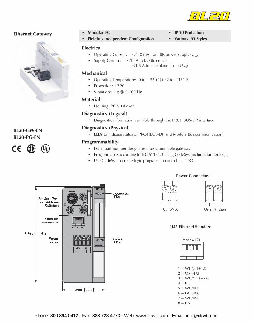
BL20-GW-ENBL20-PG-EN
Ethernet Gateway • Modular I/O• Fieldbus Independent Configuration
• IP 20 Protection• Various I/O Styles
Electrical• Operating Current: <430 mA from BR power supply (USYS)• Supply Current: <10 A to I/O (from UL)
<1.5 A to backplane (from USYS)
Mechanical• Operating Temperature: 0 to +55°C (+32 to +131°F)• Protection: IP 20• Vibration: 1 g @ 5-100 Hz
Material• Housing: PC-V0 (Lexan)
Diagnostics (Logical)• Diagnostic information available through the PROFIBUS-DP interface
Diagnostics (Physical)• LEDs to indicate status of PROFIBUS-DP and Module Bus communication
Programmability• PG in part number designates a programmable gateway• Progammable according to IEC 61131.3 using CodeSys (includes ladder logic)• Use CodeSys to create logic programs to control local I/O
Power Connectors
RJ45 Ethernet Standard
1 = WH/or (+TX)2 = OR (-TX)3 = WH/GN (+RX)4 = BU5 = WH/BU6 = GN (-RX)7 = WH/BN8 = BN
Phone: 800.894.0412 - Fax: 888.723.4773 - Web: www.clrwtr.com - Email: [email protected]
BL20
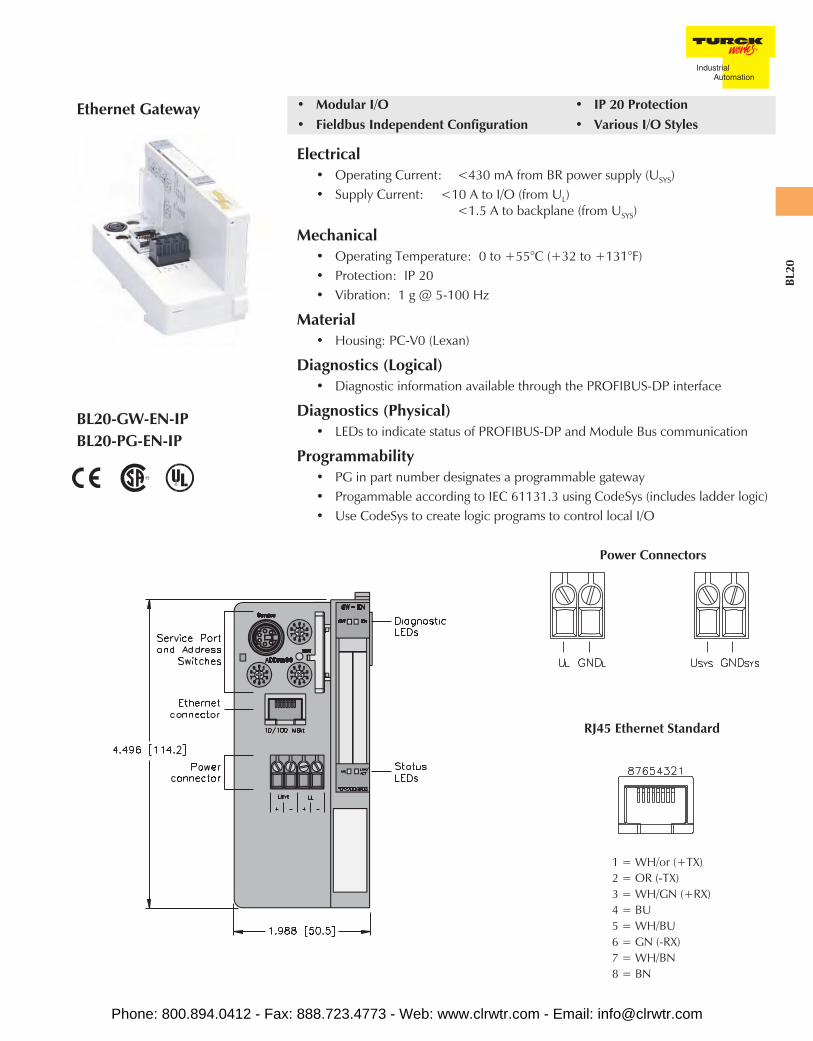
BL20-GW-EN-IPBL20-PG-EN-IP
Ethernet Gateway • Modular I/O• Fieldbus Independent Configuration
• IP 20 Protection• Various I/O Styles
Electrical• Operating Current: <430 mA from BR power supply (USYS)• Supply Current: <10 A to I/O (from UL)
<1.5 A to backplane (from USYS)
Mechanical• Operating Temperature: 0 to +55°C (+32 to +131°F)• Protection: IP 20• Vibration: 1 g @ 5-100 Hz
Material• Housing: PC-V0 (Lexan)
Diagnostics (Logical)• Diagnostic information available through the PROFIBUS-DP interface
Diagnostics (Physical)• LEDs to indicate status of PROFIBUS-DP and Module Bus communication
Programmability• PG in part number designates a programmable gateway• Progammable according to IEC 61131.3 using CodeSys (includes ladder logic)• Use CodeSys to create logic programs to control local I/O
Power Connectors
RJ45 Ethernet Standard
1 = WH/or (+TX)2 = OR (-TX)3 = WH/GN (+RX)4 = BU5 = WH/BU6 = GN (-RX)7 = WH/BN8 = BN
Phone: 800.894.0412 - Fax: 888.723.4773 - Web: www.clrwtr.com - Email: [email protected]
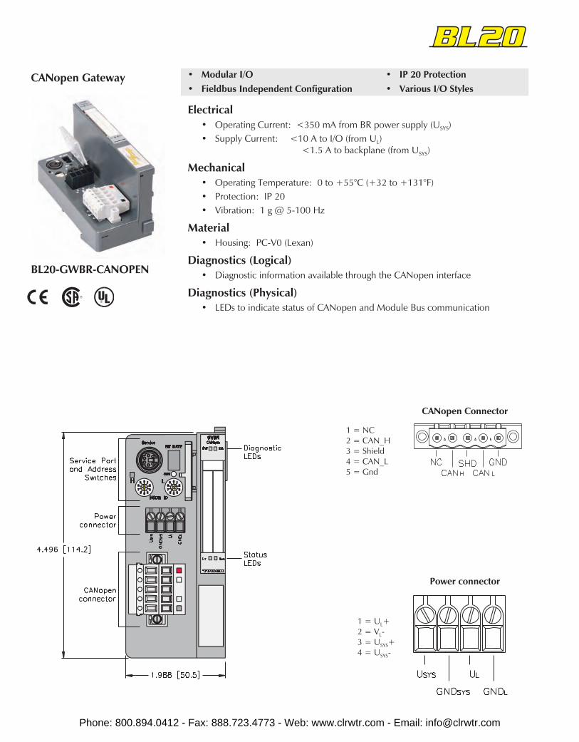
BL20-GWBR-CANOPEN
CANopen Gateway • Modular I/O• Fieldbus Independent Configuration
• IP 20 Protection• Various I/O Styles
Electrical• Operating Current: <350 mA from BR power supply (USYS)• Supply Current: <10 A to I/O (from UL)
<1.5 A to backplane (from USYS)
Mechanical• Operating Temperature: 0 to +55°C (+32 to +131°F)• Protection: IP 20• Vibration: 1 g @ 5-100 Hz
Material• Housing: PC-V0 (Lexan)
Diagnostics (Logical)• Diagnostic information available through the CANopen interface
Diagnostics (Physical)• LEDs to indicate status of CANopen and Module Bus communication
1 = NC2 = CAN_H3 = Shield4 = CAN_L5 = Gnd
CANopen Connector
1 = UL+2 = VL-3 = USYS+4 = USYS-
Power connector
Phone: 800.894.0412 - Fax: 888.723.4773 - Web: www.clrwtr.com - Email: [email protected]

BL20-2DI-24VDC-NBL20-2DI-24VDC-PBL20-4DI-24VDC-NBL20-4DI-24VDC-P (shown)
Discrete Input Modules • Modular I/O• Fieldbus Independent Configuration
• IP 20 Protection• Various I/O Styles
Electrical• Operating Current: <28 mA from VMB
<20 mA from VIO (...-2DI...)<40 mA from VIO (...-4DI...)
Power Distribution• Inputs: VIO
• Logic: VMB and VIO
Mechanical• Operating Temperature: 0 to +55°C (+32 to +131°F)• Protection: IP 20
Diagnostics• LED to indicate module bus communication status as well as I/O diagnostics• LEDs for each I/O point to indicate on/off status
Phone: 800.894.0412 - Fax: 888.723.4773 - Web: www.clrwtr.com - Email: [email protected]

BL20
Part Number Inpu
t Cou
nt
Pino
ut
Styl
e
Gro
upD
iagn
ostic
sIn
divi
dual
Dia
gnos
tics
Wire
-Bre
akD
etec
tion
I/OM
ap
BL20-2DI-24VDC-P withBL20-S3*-SBB** 2 B20-3A PNP 1
BL20-2DI-24VDC-N withBL20-S3*-SBB** 2 B20-3A NPN 1
BL20-4DI-24VDC-P withBL20-S6*-SBBSBB** 4 B20-6A PNP 2
BL20-4DI-24VDC-N withBL20-S6*-SBBSBB** 4 B20-6A NPN 2
* T = Tension clampS = Screw clamp
** Base modules sold separately. See page C58 - C61.
Inputs Data
In
Byte Bit 7 Bit 6 Bit 5 Bit 4 Bit 3 Bit 2 Bit 1 Bit 0
n–1 (Data from modules to the left)
n Data from next discrete modules I-1 I-0
n+1 (Data from modules to the right)
I/O Data Map 1
In
Byte Bit 7 Bit 6 Bit 5 Bit 4 Bit 3 Bit 2 Bit 1 Bit 0
n–1 (Data from modules to the left)
n Data from next discretemodules I-3 I-2 I-1 I-0
n+1 (Data from modules to the right)
I/O Data Map 2
B20-6AB20-3A
Input Connectors
Phone: 800.894.0412 - Fax: 888.723.4773 - Web: www.clrwtr.com - Email: [email protected]

BL20-E-8DI-24VDC-PBL20-E-16DI-24VDC-P
16DI..
Discrete Input EconomyModule
• Modular I/O• Fieldbus Independent Configuration• IP 20 Protection
• Base and Electronics in OnePart
Electrical• Operating Current: <30 mA from VMB
<2 mA from VIO
Power Distribution• Inputs: VIO
• Logic: VMB and VIO
Mechanical• Operating Temperature: 0 to +55°C (+32 to +131°F)• Protection: IP 20
Diagnostics• LED to indicate module bus communication status as well as I/O diagnostics• LEDs for each I/O point to indicate on/off status
8DI..
Phone: 800.894.0412 - Fax: 888.723.4773 - Web: www.clrwtr.com - Email: [email protected]

BL20
Part Number Coun
t
Pino
ut
Styl
e
Gro
upD
iagn
ostic
sIn
divi
dual
Dia
gnos
tics
Wire
-Bre
akD
etec
tion
I/OM
ap
BL20-E-8DI-24VDC-P 8 B20-E1 PNP 1
BL20-E-16DI-24VDC-P 16 B20-E2 PNP 2
Note: This module can only be used with other tension clamp modules.
Inputs Data
In
Byte Bit 7 Bit 6 Bit 5 Bit 4 Bit 3 Bit 2 Bit 1 Bit 0
n–1 (Data from modules to the left)
n I-7 I-6 I-5 I-4 I-3 I-2 I-1 I-0
n+1 I-8 I-9 I-10 I-11 I-12 I-13 I-14 I-15
n+2 (Data from right)
I/O Data Map 2
B20-E2
Input Connectors
12345678
1
2
3
4
5
6
7
8
9
10
8Dlp24 Vdc
DIA
B20-E1
In
Byte Bit 7 Bit 6 Bit 5 Bit 4 Bit 3 Bit 2 Bit 1 Bit 0
n–1 (Data from modules to the left)
n I-7 I-6 I-5 I-4 I-3 I-2 I-1 I-0
n+1 (Data from modules to the right)
I/O Data Map 1
Phone: 800.894.0412 - Fax: 888.723.4773 - Web: www.clrwtr.com - Email: [email protected]
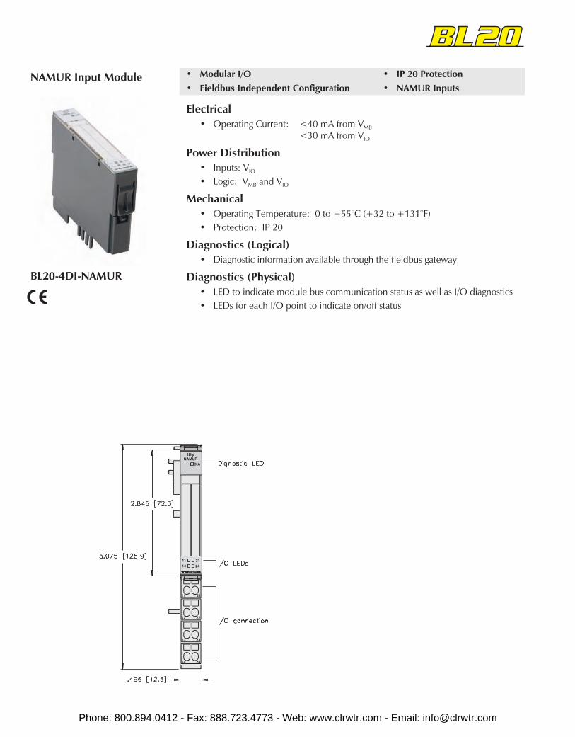
BL20-4DI-NAMUR
NAMUR Input Module • Modular I/O• Fieldbus Independent Configuration
• IP 20 Protection• NAMUR Inputs
Electrical• Operating Current: <40 mA from VMB
<30 mA from VIO
Power Distribution• Inputs: VIO
• Logic: VMB and VIO
Mechanical• Operating Temperature: 0 to +55°C (+32 to +131°F)• Protection: IP 20
Diagnostics (Logical)• Diagnostic information available through the fieldbus gateway
Diagnostics (Physical)• LED to indicate module bus communication status as well as I/O diagnostics• LEDs for each I/O point to indicate on/off status
Phone: 800.894.0412 - Fax: 888.723.4773 - Web: www.clrwtr.com - Email: [email protected]

BL20
Part Number Inpu
t Cou
nt
Pino
ut
Styl
e
Gro
upD
iagn
ostic
sIn
divi
dual
Dia
gnos
tics
Wire
-Bre
akD
etec
tion
I/OM
ap
BL20-4DI-NAMUR withBL20-S4*-SBBS** 4 B20-4C NAMUR X 1
* T = Tension clampS = Screw clamp
** Base modules sold separately. See page C58 - C61.
Inputs Data
In
Byte Bit 7 Bit 6 Bit 5 Bit 4 Bit 3 Bit 2 Bit 1 Bit 0
n–1 (Data from modules to the left)
n S-3 S-2 S-1 S-0 I-3 I-2 I-1 I-0
n+1 (Data from modules to the right)
I/O Data Map 1
B20-4C
Note: S = status bit
Input Connectors
Phone: 800.894.0412 - Fax: 888.723.4773 - Web: www.clrwtr.com - Email: [email protected]
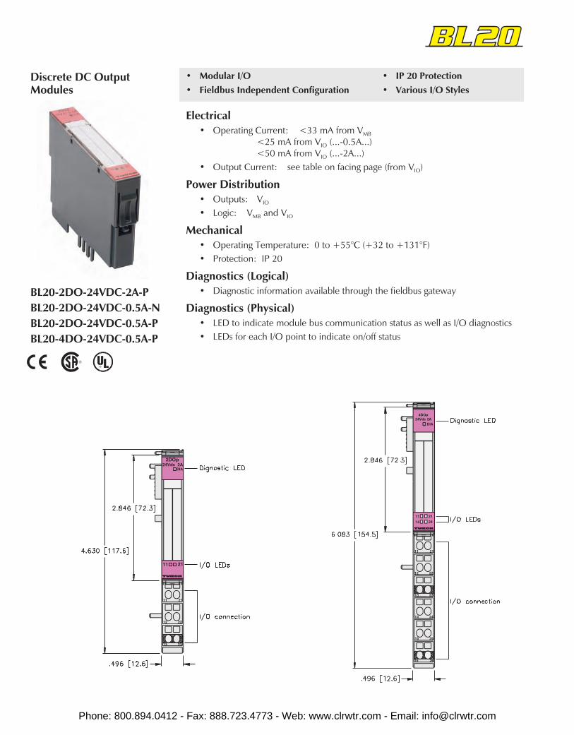
BL20-2DO-24VDC-2A-PBL20-2DO-24VDC-0.5A-NBL20-2DO-24VDC-0.5A-PBL20-4DO-24VDC-0.5A-P
Discrete DC OutputModules
• Modular I/O• Fieldbus Independent Configuration
• IP 20 Protection• Various I/O Styles
Electrical• Operating Current: <33 mA from VMB
<25 mA from VIO (...-0.5A...)<50 mA from VIO (...-2A...)
• Output Current: see table on facing page (from VIO)
Power Distribution• Outputs: VIO
• Logic: VMB and VIO
Mechanical• Operating Temperature: 0 to +55°C (+32 to +131°F)• Protection: IP 20
Diagnostics (Logical)• Diagnostic information available through the fieldbus gateway
Diagnostics (Physical)• LED to indicate module bus communication status as well as I/O diagnostics• LEDs for each I/O point to indicate on/off status
Phone: 800.894.0412 - Fax: 888.723.4773 - Web: www.clrwtr.com - Email: [email protected]
BL20
Part Number Inpu
t Cou
nt
Pino
ut
Curr
ent
Indi
vidu
alD
iagn
ostic
sW
ire-B
reak
Det
ectio
n
I/OM
ap
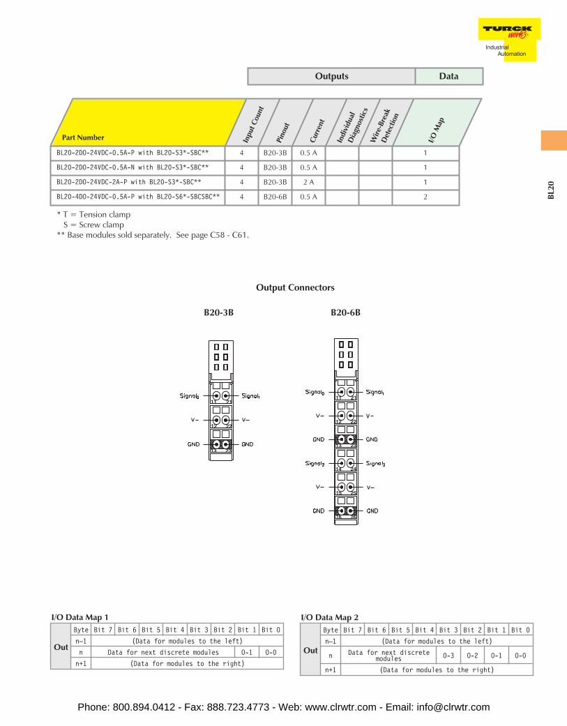
BL20-2DO-24VDC-0.5A-P with BL20-S3*-SBC** 4 B20-3B 0.5 A 1
BL20-2DO-24VDC-0.5A-N with BL20-S3*-SBC** 4 B20-3B 0.5 A 1
BL20-2DO-24VDC-2A-P with BL20-S3*-SBC** 4 B20-3B 2 A 1
BL20-4DO-24VDC-0.5A-P with BL20-S6*-SBCSBC** 4 B20-6B 0.5 A 2
* T = Tension clampS = Screw clamp
** Base modules sold separately. See page C58 - C61.
Outputs Data
Out
Byte Bit 7 Bit 6 Bit 5 Bit 4 Bit 3 Bit 2 Bit 1 Bit 0
n–1 (Data for modules to the left)
n Data for next discretemodules O-3 O-2 O-1 O-0
n+1 (Data for modules to the right)
I/O Data Map 2
Out
Byte Bit 7 Bit 6 Bit 5 Bit 4 Bit 3 Bit 2 Bit 1 Bit 0
n–1 (Data for modules to the left)
n Data for next discrete modules O-1 O-0
n+1 (Data for modules to the right)
I/O Data Map 1
B20-6BB20-3B
Output Connectors
Phone: 800.894.0412 - Fax: 888.723.4773 - Web: www.clrwtr.com - Email: [email protected]
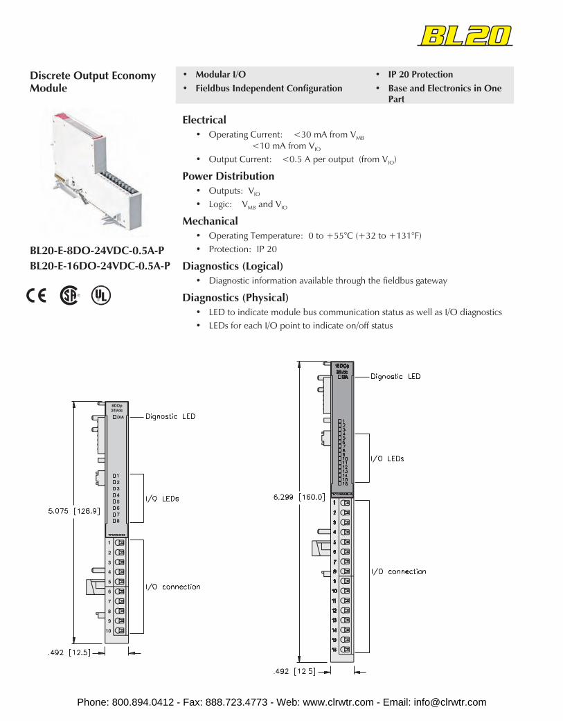
BL20-E-8DO-24VDC-0.5A-PBL20-E-16DO-24VDC-0.5A-P
Discrete Output EconomyModule
• Modular I/O• Fieldbus Independent Configuration
• IP 20 Protection• Base and Electronics in One
Part
Electrical• Operating Current: <30 mA from VMB
<10 mA from VIO
• Output Current: <0.5 A per output (from VIO)
Power Distribution• Outputs: VIO
• Logic: VMB and VIO
Mechanical• Operating Temperature: 0 to +55°C (+32 to +131°F)• Protection: IP 20
Diagnostics (Logical)• Diagnostic information available through the fieldbus gateway
Diagnostics (Physical)• LED to indicate module bus communication status as well as I/O diagnostics• LEDs for each I/O point to indicate on/off status
Phone: 800.894.0412 - Fax: 888.723.4773 - Web: www.clrwtr.com - Email: [email protected]

BL20
Part Number Inpu
t Cou
nt
Pino
ut
Curr
ent
Indi
vidu
alD
iagn
ostic
s
Wire
-Bre
akD
etec
tion
I/OM
ap
BL20-E-8DO-24VDC-0.5A-P 8 BO-E1 0.5 A X 1
BL20-E-16DO-24VDC-0.5A-P 16 BO-E2 0.5 A X 2
Outputs Data
Out
Byte Bit 7 Bit 6 Bit 5 Bit 4 Bit 3 Bit 2 Bit 1 Bit 0
n–1 (Data for modules to the left)
n O-7 O-6 O-5 O-4 O-3 O-2 O-1 O-0
n+1 0-8 O-9 O-10 O-11 O-12 O-13 O-14 O-15
n+2 (Data from right)
I/O Data Map 2
BO-E2
Output Connectors
12345678
1
2
3
4
5
6
7
8
9
10
8DOp24Vdc 0.5A
DIA
BO-E1
Out
Byte Bit 7 Bit 6 Bit 5 Bit 4 Bit 3 Bit 2 Bit 1 Bit 0
n–1 (Data for modules to the left)
n O-7 O-6 O-5 O-4 O-3 O-2 O-1 O-0
n+1 (Data for modules to the right)
I/O Data Map 1
Phone: 800.894.0412 - Fax: 888.723.4773 - Web: www.clrwtr.com - Email: [email protected]

BL20-2DO-R-COBL20-2DO-R-NOBL20-2DO-R-NC
Discrete relay OutputModules
• Modular I/O• Fieldbus Independent Configuration
• IP 20 Protection• Relay Outputs
Electrical• Operating Current: <28 mA from VMB
<20 mA from VIO
Power Distribution• Outputs: VIO
• Logic: VMB and VIO
Mechanical• Operating Temperature: 0 to +55°C (+32 to +131°F)• Protection: IP 20
Diagnostics (Logical)• Diagnostic information available through the fieldbus gateway
Diagnostics (Physical)• LED to indicate module bus communication status as well as I/O diagnostics• LEDs for each I/O point to indicate on/off status
Phone: 800.894.0412 - Fax: 888.723.4773 - Web: www.clrwtr.com - Email: [email protected]

BL20
Outputs Data
Out
Byte Bit 7 Bit 6 Bit 5 Bit 4 Bit 3 Bit 2 Bit 1 Bit 0
n–1 (Data for modules to the left)
n Data for next discrete modules O-1 O-0
n+1 (Data for modules to the right)
I/O Data Map 1
B20-4A
Part Number Coun
t
Pino
ut
Curr
ent
Indi
vidu
alD
iagn
ostic
sW
ire-B
reak
Det
ectio
n
I/OM
ap
BL20-2DO-R-NO with BL20-S4*-SBCS** 2 B20-4A 2 A 1
BL20-2DO-R-NC with BL20-S4*-SBCS** 2 B20-4A 2 A 1
BL20-2DO-R-CO with BL20-S4*-SBBS** 2 B20-4B 2 A 1
* T = Tension clampS = Screw clamp
** Base modules sold separately. See pages C58 - C61.
B20-4B
Output Connectors
Phone: 800.894.0412 - Fax: 888.723.4773 - Web: www.clrwtr.com - Email: [email protected]
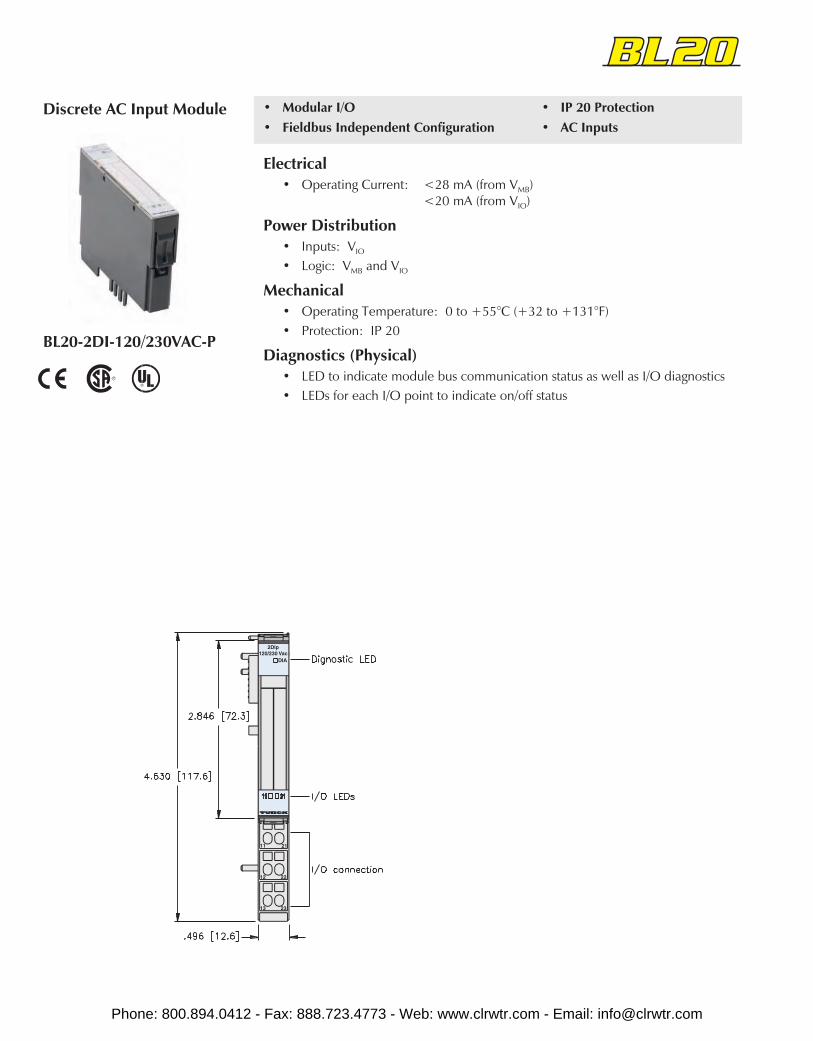
BL20-2DI-120/230VAC-P
Discrete AC Input Module
Electrical• Operating Current: <28 mA (from VMB)
<20 mA (from VIO)
Power Distribution• Inputs: VIO
• Logic: VMB and VIO
Mechanical• Operating Temperature: 0 to +55°C (+32 to +131°F)• Protection: IP 20
Diagnostics (Physical)• LED to indicate module bus communication status as well as I/O diagnostics• LEDs for each I/O point to indicate on/off status
• Modular I/O• Fieldbus Independent Configuration
• IP 20 Protection• AC Inputs
Phone: 800.894.0412 - Fax: 888.723.4773 - Web: www.clrwtr.com - Email: [email protected]
BL20
Part Number Inpu
t Cou
nt
Pino
ut
Styl
e
Gro
upD
iagn
ostic
sIn
divi
dual
Dia
gnos
tics
Wire
-Bre
akD
etec
tion
I/O Map
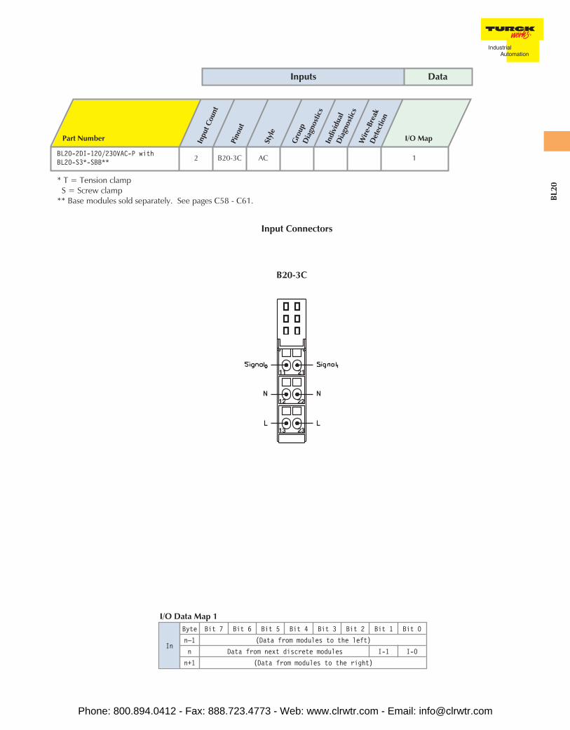
BL20-2DI-120/230VAC-P withBL20-S3*-SBB** 2 B20-3C AC 1
* T = Tension clampS = Screw clamp
** Base modules sold separately. See pages C58 - C61.
Inputs Data
In
Byte Bit 7 Bit 6 Bit 5 Bit 4 Bit 3 Bit 2 Bit 1 Bit 0
n–1 (Data from modules to the left)
n Data from next discrete modules I-1 I-0
n+1 (Data from modules to the right)
I/O Data Map 1
B20-3C
Input Connectors
Phone: 800.894.0412 - Fax: 888.723.4773 - Web: www.clrwtr.com - Email: [email protected]
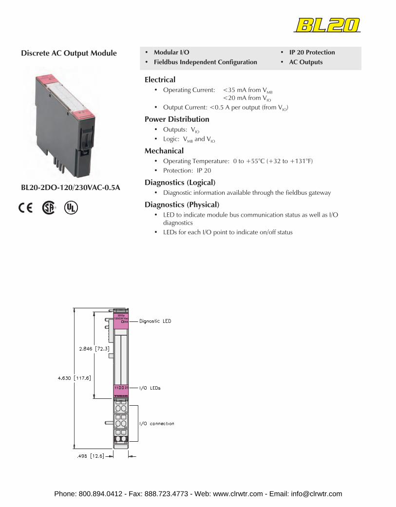
BL20-2DO-120/230VAC-0.5A
Discrete AC Output Module • Modular I/O• Fieldbus Independent Configuration
• IP 20 Protection• AC Outputs
Electrical• Operating Current: <35 mA from VMB
<20 mA from VIO
• Output Current: <0.5 A per output (from VIO)
Power Distribution• Outputs: VIO
• Logic: VMB and VIO
Mechanical• Operating Temperature: 0 to +55°C (+32 to +131°F)• Protection: IP 20
Diagnostics (Logical)• Diagnostic information available through the fieldbus gateway
Diagnostics (Physical)• LED to indicate module bus communication status as well as I/O
diagnostics• LEDs for each I/O point to indicate on/off status
Phone: 800.894.0412 - Fax: 888.723.4773 - Web: www.clrwtr.com - Email: [email protected]

BL20
Part Number Out
put
Coun
t
Pino
ut
Curr
ent
Indi
vidu
alD
iagn
ostic
sW
ire-B
reak
Det
ectio
n
I/OM
ap
BL20-2DO-120/230VAC-0.5A-P withBL20-S3*-SBC** 2 B20-3B 0.5 A 1
* T = Tension clampS = Screw clamp
** Base modules sold separately. See pages C58 - C61.
Outputs Data
Out
Byte Bit 7 Bit 6 Bit 5 Bit 4 Bit 3 Bit 2 Bit 1 Bit 0
n–1 (Data for modules to the left)
n Data for next discrete modules O-1 O-0
n+1 (Data for modules to the right)
I/O Data Map 1
B20-3B
Output Connectors
Phone: 800.894.0412 - Fax: 888.723.4773 - Web: www.clrwtr.com - Email: [email protected]
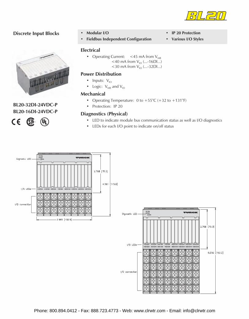
BL20-32DI-24VDC-PBL20-16DI-24VDC-P
Discrete Input Blocks • Modular I/O• Fieldbus Independent Configuration
• IP 20 Protection• Various I/O Styles
Electrical• Operating Current: <45 mA from VMB
<40 mA from VIO (...-16DI...)<30 mA from VIO (...-32DI...)
Power Distribution• Inputs: VIO
• Logic: VMB and VIO
Mechanical• Operating Temperature: 0 to +55°C (+32 to +131°F)• Protection: IP 20
Diagnostics (Physical)• LED to indicate module bus communication status as well as I/O diagnostics• LEDs for each I/O point to indicate on/off status
Phone: 800.894.0412 - Fax: 888.723.4773 - Web: www.clrwtr.com - Email: [email protected]
BL20
Part Number Inpu
t Cou
nt
Pino
ut
Styl
e
Gro
upD
iagn
ostic
sIn
divi
dual
Dia
gnos
tics
Wire
-Bre
akD
etec
tion
I/OM
ap
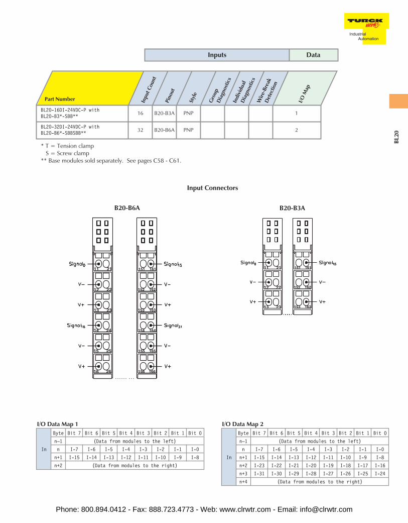
BL20-16DI-24VDC-P withBL20-B3*-SBB** 16 B20-B3A PNP 1
BL20-32DI-24VDC-P withBL20-B6*-SBBSBB** 32 B20-B6A PNP 2
* T = Tension clampS = Screw clamp
** Base modules sold separately. See pages C58 - C61.
Inputs Data
In
Byte Bit 7 Bit 6 Bit 5 Bit 4 Bit 3 Bit 2 Bit 1 Bit 0
n–1 (Data from modules to the left)
n I-7 I-6 I-5 I-4 I-3 I-2 I-1 I-0
n+1 I-15 I-14 I-13 I-12 I-11 I-10 I-9 I-8
n+2 (Data from modules to the right)
I/O Data Map 1
In
Byte Bit 7 Bit 6 Bit 5 Bit 4 Bit 3 Bit 2 Bit 1 Bit 0
n–1 (Data from modules to the left)
n I-7 I-6 I-5 I-4 I-3 I-2 I-1 I-0
n+1 I-15 I-14 I-13 I-12 I-11 I-10 I-9 I-8
n+2 I-23 I-22 I-21 I-20 I-19 I-18 I-17 I-16
n+3 I-31 I-30 I-29 I-28 I-27 I-26 I-25 I-24
n+4 (Data from modules to the right)
I/O Data Map 2
B20-B6A B20-B3A
Input Connectors
Phone: 800.894.0412 - Fax: 888.723.4773 - Web: www.clrwtr.com - Email: [email protected]
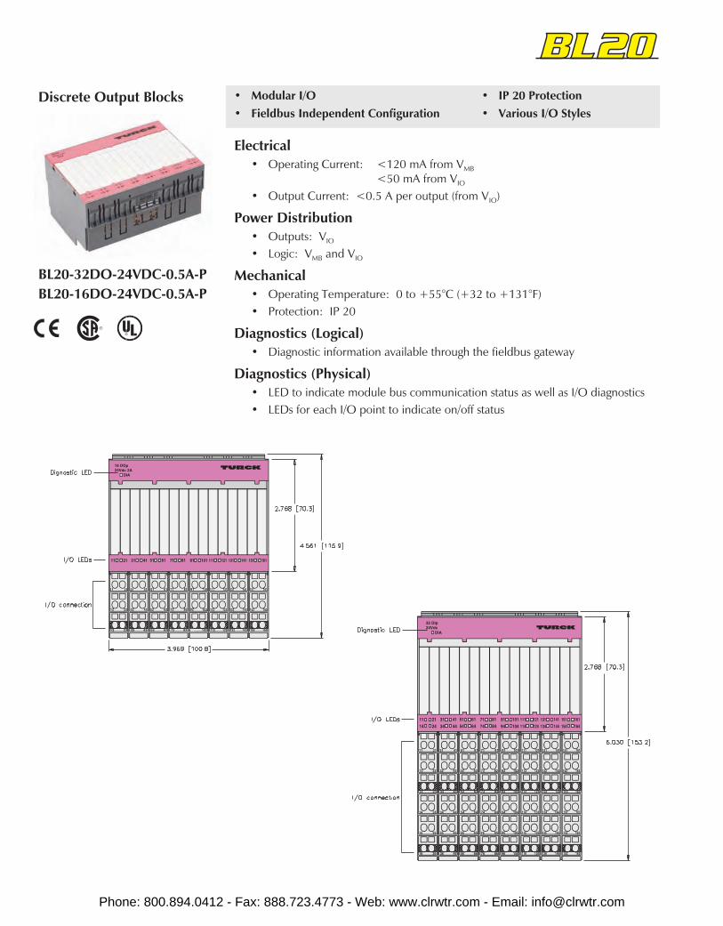
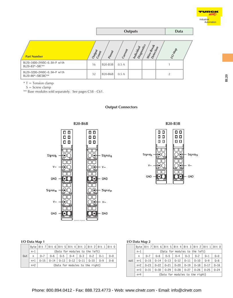
BL20-32DO-24VDC-0.5A-PBL20-16DO-24VDC-0.5A-P
Discrete Output Blocks • Modular I/O• Fieldbus Independent Configuration
• IP 20 Protection• Various I/O Styles
Electrical• Operating Current: <120 mA from VMB
<50 mA from VIO
• Output Current: <0.5 A per output (from VIO)
Power Distribution• Outputs: VIO
• Logic: VMB and VIO
Mechanical• Operating Temperature: 0 to +55°C (+32 to +131°F)• Protection: IP 20
Diagnostics (Logical)• Diagnostic information available through the fieldbus gateway
Diagnostics (Physical)• LED to indicate module bus communication status as well as I/O diagnostics• LEDs for each I/O point to indicate on/off status
Phone: 800.894.0412 - Fax: 888.723.4773 - Web: www.clrwtr.com - Email: [email protected]
BL20
Part Number Out
put
Coun
t
Pino
ut
Curr
ent
Indi
vidu
alD
iagn
ostic
sW
ire-B
reak
Det
ectio
n
I/OM
ap
BL20-16DO-24VDC-0.5A-P withBL20-B3*-SBC** 16 B20-B3B 0.5 A 1
BL20-32DO-24VDC-0.5A-P withBL20-B6*-SBCSBC** 32 B20-B6B 0.5 A 2
* T = Tension clampS = Screw clamp
** Base modules sold separately. See pages C58 - C61.
Outputs Data
out
Byte Bit 7 Bit 6 Bit 5 Bit 4 Bit 3 Bit 2 Bit 1 Bit 0
n–1 (Data for modules to the left)
n O-7 O-6 O-5 O-4 O-3 O-2 O-1 O-0
n+1 O-15 O-14 O-13 O-12 O-11 O-10 O-9 O-8
n+2 O-23 O-22 O-21 O-20 O-19 O-18 O-17 O-16
n+3 O-31 O-30 O-29 O-28 O-27 O-26 O-25 O-24
n+4 (Data for modules to the right)
I/O Data Map 2
Out
Byte Bit 7 Bit 6 Bit 5 Bit 4 Bit 3 Bit 2 Bit 1 Bit 0
n–1 (Data for modules to the left)
n O-7 O-6 O-5 O-4 O-3 O-2 O-1 O-0
n+1 O-15 O-14 O-13 O-12 O-11 O-10 O-9 O-8
n+2 (Data for modules to the right)
I/O Data Map 1
B20-B6B B20-B3B
Output Connectors
Phone: 800.894.0412 - Fax: 888.723.4773 - Web: www.clrwtr.com - Email: [email protected]
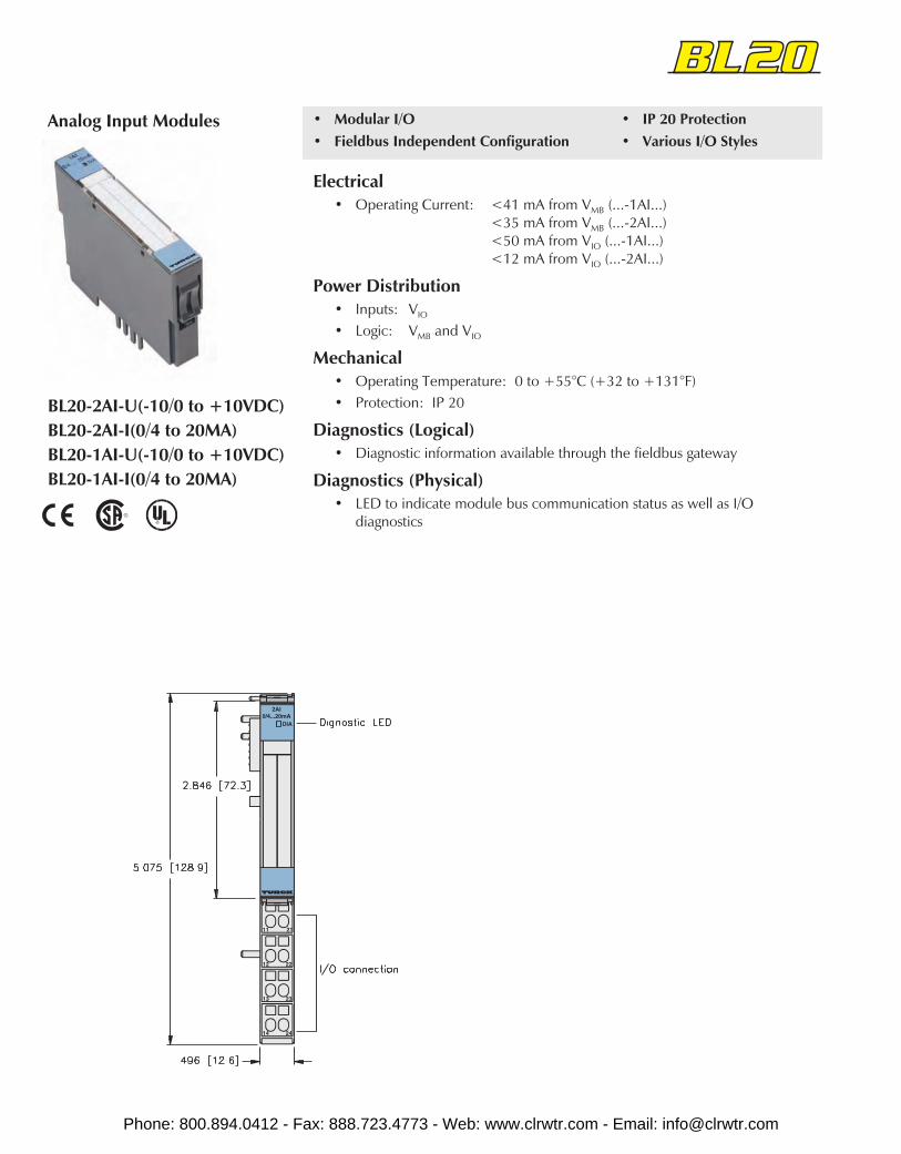
BL20-2AI-U(-10/0 to +10VDC)BL20-2AI-I(0/4 to 20MA)BL20-1AI-U(-10/0 to +10VDC)BL20-1AI-I(0/4 to 20MA)
Analog Input Modules • Modular I/O• Fieldbus Independent Configuration
• IP 20 Protection• Various I/O Styles
Electrical• Operating Current: <41 mA from VMB (...-1AI...)
<35 mA from VMB (...-2AI...)<50 mA from VIO (...-1AI...)<12 mA from VIO (...-2AI...)
Power Distribution• Inputs: VIO
• Logic: VMB and VIO
Mechanical• Operating Temperature: 0 to +55°C (+32 to +131°F)• Protection: IP 20
Diagnostics (Logical)• Diagnostic information available through the fieldbus gateway
Diagnostics (Physical)• LED to indicate module bus communication status as well as I/O
diagnostics
Phone: 800.894.0412 - Fax: 888.723.4773 - Web: www.clrwtr.com - Email: [email protected]
BL20
Part Number Inpu
t Cou
nt
Pino
ut
Styl
e
Gro
upD
iagn
ostic
sIn
divi
dual
Dia
gnos
tics
Wire
-Bre
akD
etec
tion
I/OM
ap
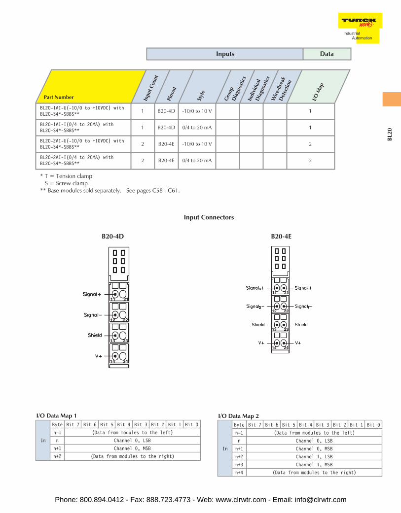
BL20-1AI-U(-10/0 to +10VDC) withBL20-S4*-SBBS** 1 B20-4D -10/0 to 10 V 1
BL20-1AI-I(0/4 to 20MA) withBL20-S4*-SBBS** 1 B20-4D 0/4 to 20 mA 1
BL20-2AI-U(-10/0 to +10VDC) withBL20-S4*-SBBS** 2 B20-4E -10/0 to 10 V 2
BL20-2AI-I(0/4 to 20MA) withBL20-S4*-SBBS** 2 B20-4E 0/4 to 20 mA 2
* T = Tension clampS = Screw clamp
** Base modules sold separately. See pages C58 - C61.
Inputs Data
In
Byte Bit 7 Bit 6 Bit 5 Bit 4 Bit 3 Bit 2 Bit 1 Bit 0
n–1 (Data from modules to the left)
n Channel 0, LSB
n+1 Channel 0, MSB
n+2 Channel 1, LSB
n+3 Channel 1, MSB
n+4 (Data from modules to the right)
I/O Data Map 2
In
Byte Bit 7 Bit 6 Bit 5 Bit 4 Bit 3 Bit 2 Bit 1 Bit 0
n–1 (Data from modules to the left)
n Channel 0, LSB
n+1 Channel 0, MSB
n+2 (Data from modules to the right)
I/O Data Map 1
B20-4D B20-4E
Input Connectors
Phone: 800.894.0412 - Fax: 888.723.4773 - Web: www.clrwtr.com - Email: [email protected]
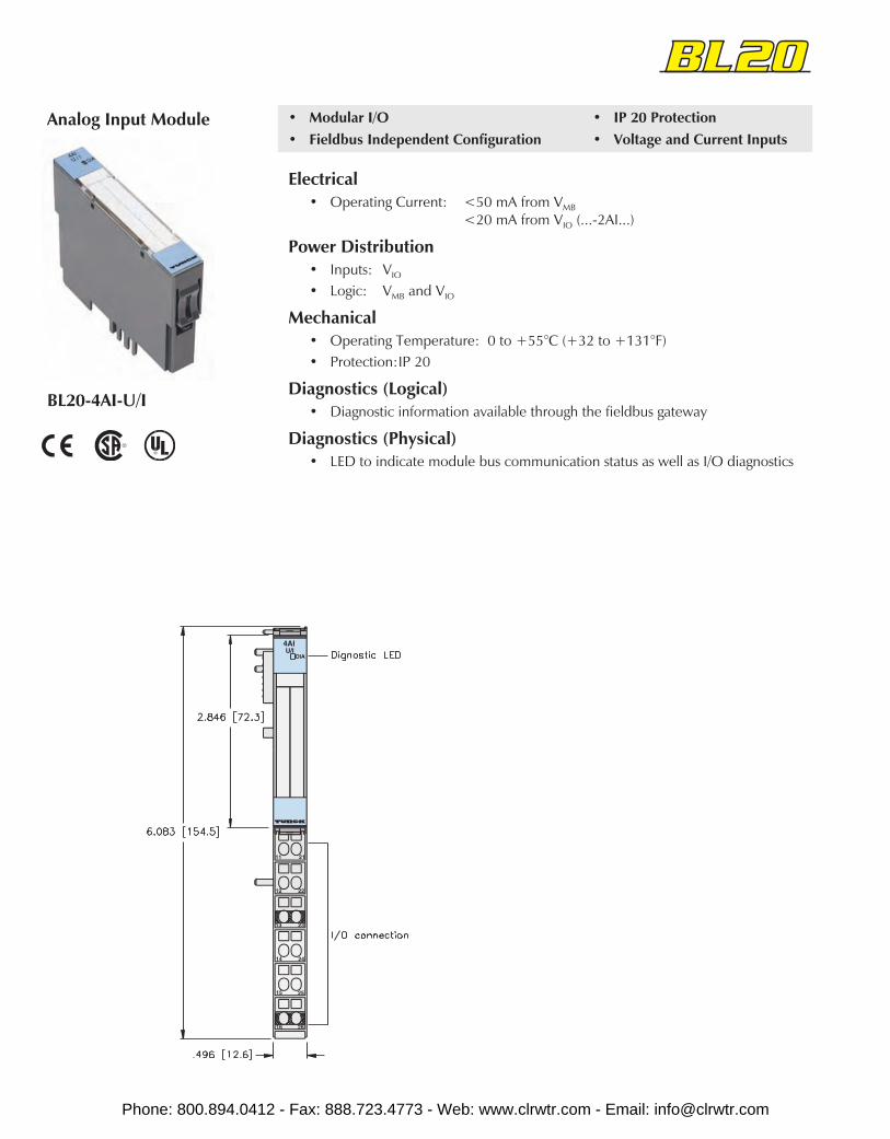
BL20-4AI-U/I
Analog Input Module • Modular I/O• Fieldbus Independent Configuration
• IP 20 Protection• Voltage and Current Inputs
Electrical• Operating Current: <50 mA from VMB
<20 mA from VIO (...-2AI...)
Power Distribution• Inputs: VIO
• Logic: VMB and VIO
Mechanical• Operating Temperature: 0 to +55°C (+32 to +131°F)• Protection:IP 20
Diagnostics (Logical)• Diagnostic information available through the fieldbus gateway
Diagnostics (Physical)• LED to indicate module bus communication status as well as I/O diagnostics
Phone: 800.894.0412 - Fax: 888.723.4773 - Web: www.clrwtr.com - Email: [email protected]
BL20
Part Number Inpu
t Cou
nt
Pino
ut
Styl
e
Gro
upD
iagn
ostic
sIn
divi
dual
Dia
gnos
tics
Wire
-Bre
akD
etec
tion
I/OM
ap
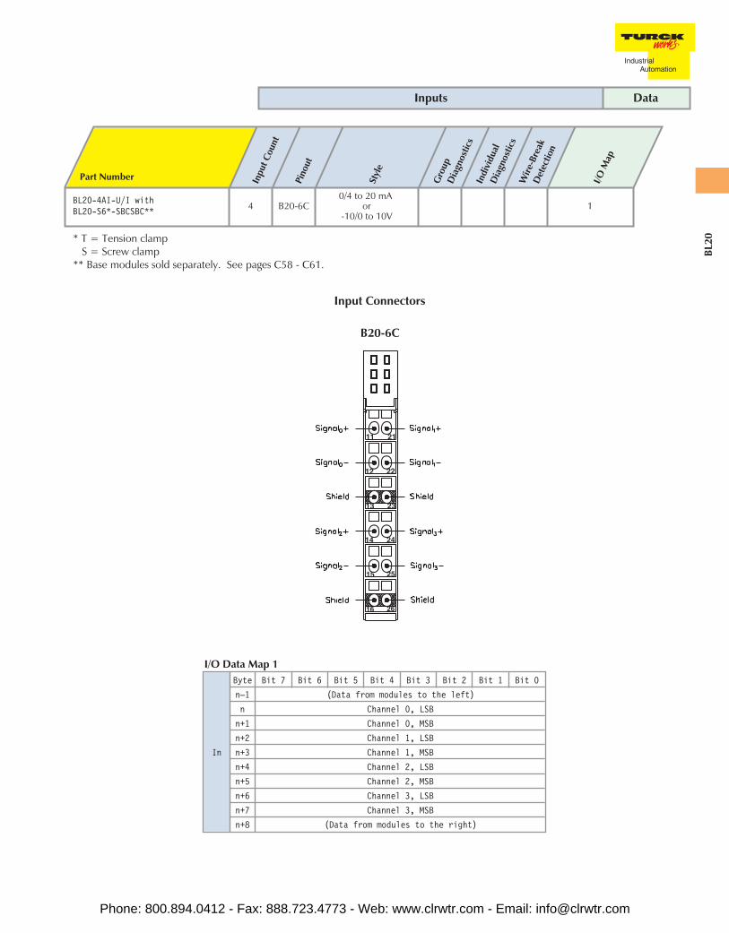
BL20-4AI-U/I withBL20-S6*-SBCSBC** 4 B20-6C
0/4 to 20 mAor
-10/0 to 10V1
* T = Tension clampS = Screw clamp
** Base modules sold separately. See pages C58 - C61.
Inputs Data
In
Byte Bit 7 Bit 6 Bit 5 Bit 4 Bit 3 Bit 2 Bit 1 Bit 0
n–1 (Data from modules to the left)
n Channel 0, LSB
n+1 Channel 0, MSB
n+2 Channel 1, LSB
n+3 Channel 1, MSB
n+4 Channel 2, LSB
n+5 Channel 2, MSB
n+6 Channel 3, LSB
n+7 Channel 3, MSB
n+8 (Data from modules to the right)
I/O Data Map 1
B20-6C
Input Connectors
Phone: 800.894.0412 - Fax: 888.723.4773 - Web: www.clrwtr.com - Email: [email protected]

BL20-2AI-THERMO-PIBL20-2AI-PT/NI-2/3
Temperature Input Modules • Modular I/O• Fieldbus Independent Configuration
• IP 20 Protection• Thermocouple or RTD Inputs
Electrical• Operating Current: <45 mA from VMB
<30 mA from VIO
• Thermocouple Types: B, E, J, K, N, R, S, T (... THERMO-PI)• RTD Types: PT100, PT500, PT1000, Ni100, Ni1000 (...PT/Ni-2/3)
Power Distribution• Inputs: VIO
• Logic: VMB and VIO
Mechanical• Operating Temperature: 0 to +55°C (+32 to +131°F)• Protection: IP 20
Diagnostics (Logical)• Diagnostic information available through the fieldbus gateway
Diagnostics (Physical)• LED to indicate module bus communication status as well as I/O diagnostics
Phone: 800.894.0412 - Fax: 888.723.4773 - Web: www.clrwtr.com - Email: [email protected]

BL20
Part Number Inpu
t Cou
nt
Pino
ut
Styl
e
Gro
upD
iagn
ostic
s
Indi
vidu
alD
iagn
ostic
s
Wire
-Bre
akD
etec
tion
I/OM
ap
BL20-2AI-PT/NI-2/3 withBL20-S4*-SBBS** 2 B20-4F RTD 1
BL20-2AI-THERMO-PI withBL20-S4*-SBBS-CJ** 2 B20-4G TC 1
* T = Tension clampS = Screw clamp
** Base modules sold separately. See pages C58 - C61.Note: BL20-S4*-SBBS-CJ has integrated cold junction compensation fro thermocouples.
Inputs Data
In
Byte Bit 7 Bit 6 Bit 5 Bit 4 Bit 3 Bit 2 Bit 1 Bit 0
n–1 (Data from modules to the left)
n Channel 0, LSB
n+1 Channel 0, MSB
n+2 Channel 1, LSB
n+3 Channel 1, MSB
n+4 (Data from modules to the right)
I/O Data Map 1
B20-4G B20-4F
Input Connectors
Phone: 800.894.0412 - Fax: 888.723.4773 - Web: www.clrwtr.com - Email: [email protected]

BL20-2AO-I(0/4 to 20MA)BL20-2AO-U(-10/0 to +10VDC)BL20-1AO-I(0/4 to 20MA)
Analog Output Modules • Modular I/O• Fieldbus Independent Configuration
• IP 20 Protection• Various I/O Styles
Electrical• Operating Current: <43 mA (from VMB)• Sensor Current: <50 mA (from VIO)
Power Distribution• Inputs: VIO
• Logic: VMB and VIO
Mechanical• Operating Temperature: 0 to +55°C (+32 to +131°F)• Protection: IP 20
Diagnostics (Logical)• Diagnostic information available through the fieldbus gateway
Diagnostics (Physical)• LED to indicate module bus communication status as well as I/O
diagnostics
Phone: 800.894.0412 - Fax: 888.723.4773 - Web: www.clrwtr.com - Email: [email protected]
BL20
Part Number Out
put
Coun
t
Pino
ut
Styl
e
Gro
upD
iagn
ostic
sIn
divi
dual
Dia
gnos
tics
Wire
-Bre
akD
etec
tion
I/OM
ap
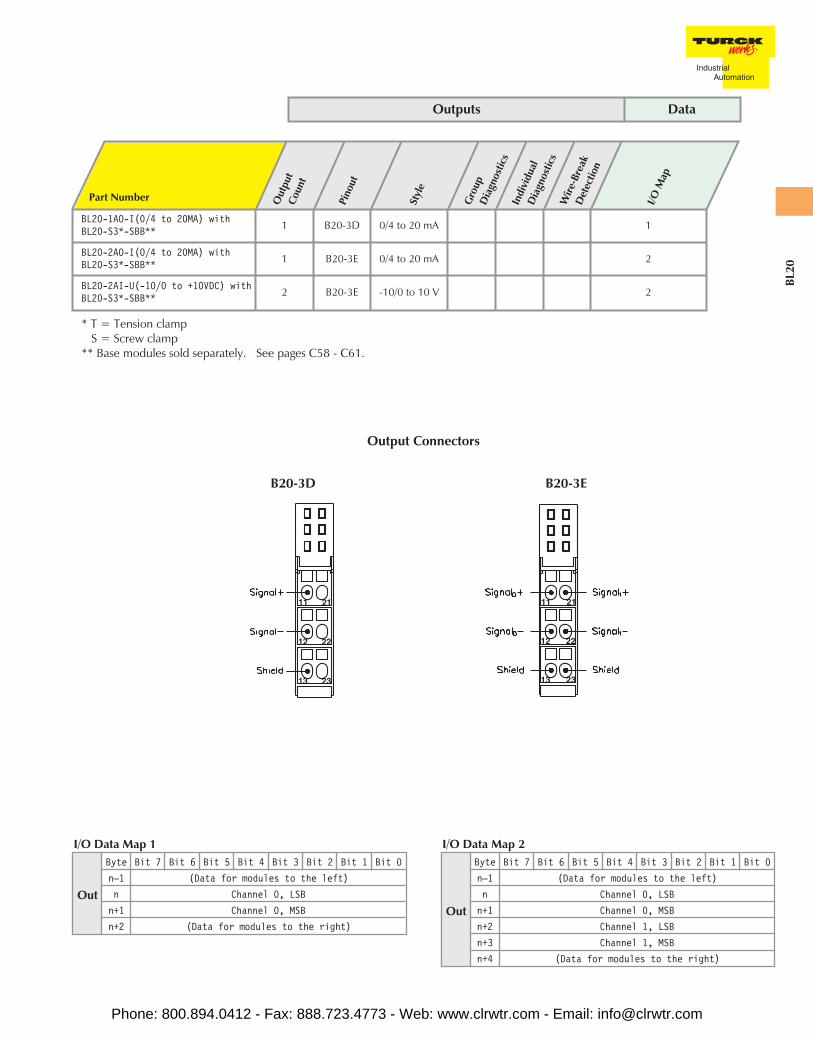
BL20-1AO-I(0/4 to 20MA) withBL20-S3*-SBB** 1 B20-3D 0/4 to 20 mA 1
BL20-2AO-I(0/4 to 20MA) withBL20-S3*-SBB** 1 B20-3E 0/4 to 20 mA 2
BL20-2AI-U(-10/0 to +10VDC) withBL20-S3*-SBB** 2 B20-3E -10/0 to 10 V 2
* T = Tension clampS = Screw clamp
** Base modules sold separately. See pages C58 - C61.
Outputs Data
Out
Byte Bit 7 Bit 6 Bit 5 Bit 4 Bit 3 Bit 2 Bit 1 Bit 0
n–1 (Data for modules to the left)
n Channel 0, LSB
n+1 Channel 0, MSB
n+2 Channel 1, LSB
n+3 Channel 1, MSB
n+4 (Data for modules to the right)
I/O Data Map 2
Out
Byte Bit 7 Bit 6 Bit 5 Bit 4 Bit 3 Bit 2 Bit 1 Bit 0
n–1 (Data for modules to the left)
n Channel 0, LSB
n+1 Channel 0, MSB
n+2 (Data for modules to the right)
I/O Data Map 1
B20-3D B20-3E
Output Connectors
Phone: 800.894.0412 - Fax: 888.723.4773 - Web: www.clrwtr.com - Email: [email protected]
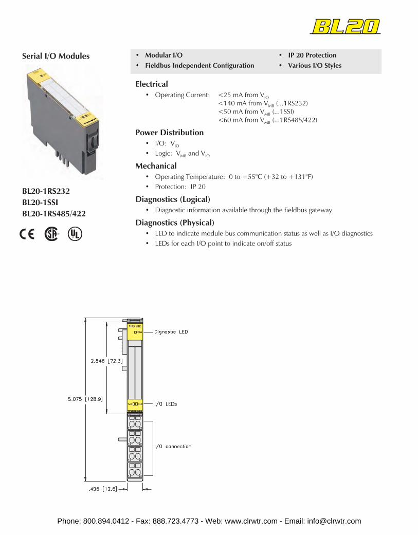
BL20-1RS232BL20-1SSIBL20-1RS485/422
Serial I/O Modules • Modular I/O• Fieldbus Independent Configuration
• IP 20 Protection• Various I/O Styles
Electrical• Operating Current: <25 mA from VIO
<140 mA from VMB (...1RS232)<50 mA from VMB (...1SSI)<60 mA from VMB (...1RS485/422)
Power Distribution• I/O: VIO
• Logic: VMB and VIO
Mechanical• Operating Temperature: 0 to +55°C (+32 to +131°F)• Protection: IP 20
Diagnostics (Logical)• Diagnostic information available through the fieldbus gateway
Diagnostics (Physical)• LED to indicate module bus communication status as well as I/O diagnostics• LEDs for each I/O point to indicate on/off status
Phone: 800.894.0412 - Fax: 888.723.4773 - Web: www.clrwtr.com - Email: [email protected]
BL20
Part Number Inpu
t Cou
nt
Pino
ut
Styl
e
Gro
upD
iagn
ostic
sIn
divi
dual
Dia
gnos
tics
Wire
-Bre
akD
etec
tion
Out
put
Coun
t
Pino
ut
Styl
e
Indi
vidu
alD
iagn
ostic
sW
ire-B
reak
Det
ectio
n
I/OM
ap
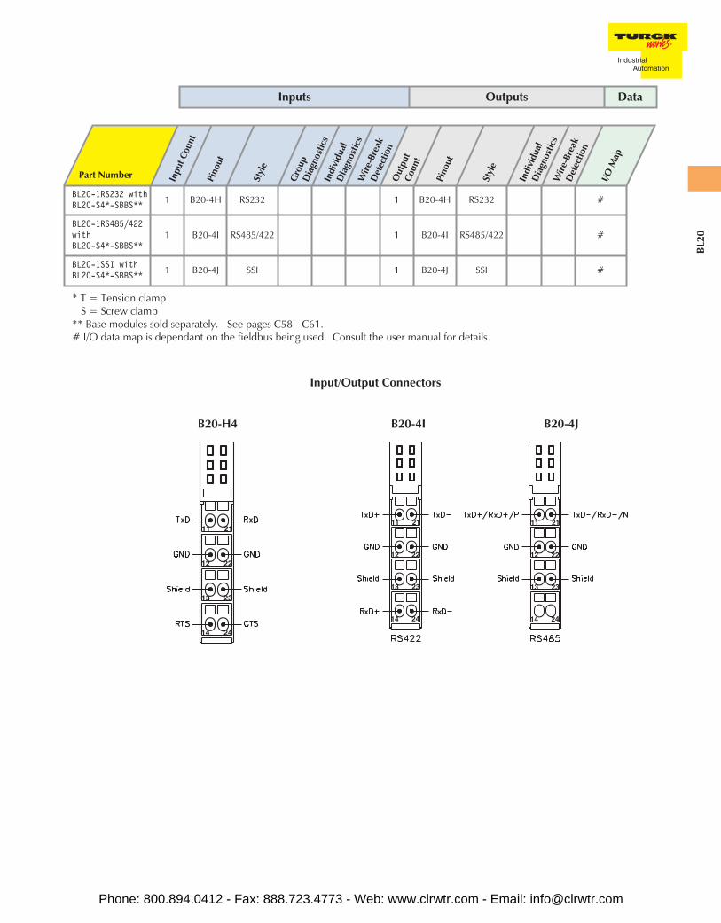
BL20-1RS232 withBL20-S4*-SBBS** 1 B20-4H RS232 1 B20-4H RS232 #
BL20-1RS485/422withBL20-S4*-SBBS**
1 B20-4I RS485/422 1 B20-4I RS485/422 #
BL20-1SSI withBL20-S4*-SBBS** 1 B20-4J SSI 1 B20-4J SSI #
* T = Tension clampS = Screw clamp
** Base modules sold separately. See pages C58 - C61.# I/O data map is dependant on the fieldbus being used. Consult the user manual for details.
Inputs Outputs Data
B20-4I B20-4JB20-H4
Input/Output Connectors
Phone: 800.894.0412 - Fax: 888.723.4773 - Web: www.clrwtr.com - Email: [email protected]
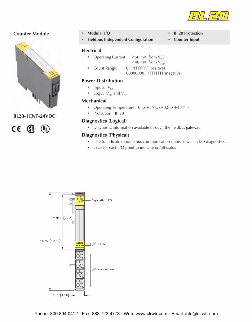
BL20-1CNT-24VDC
Counter Module • Modular I/O• Fieldbus Independent Configuration
• IP 20 Protection• Counter Input
Electrical• Operating Current: <50 mA (from VIO)
<40 mA (from VMB)• Count Range: 0...7FFFFFFF (positive)
80000000...FFFFFFFF (negative)
Power Distribution• Inputs: VIO
• Logic: VMB and VIO
Mechanical• Operating Temperature: 0 to +55°C (+32 to +131°F)• Protection: IP 20
Diagnostics (Logical)• Diagnostic information available through the fieldbus gateway
Diagnostics (Physical)• LED to indicate module bus communication status as well as I/O diagnostics• LEDs for each I/O point to indicate on/off status
Phone: 800.894.0412 - Fax: 888.723.4773 - Web: www.clrwtr.com - Email: [email protected]
BL20
Part Number Inpu
t Cou
nt
Pino
ut
Styl
e
Gro
upD
iagn
ostic
s
Indi
vidu
alD
iagn
ostic
s
Wire
-Bre
akD
etec
tion
I/OM
ap
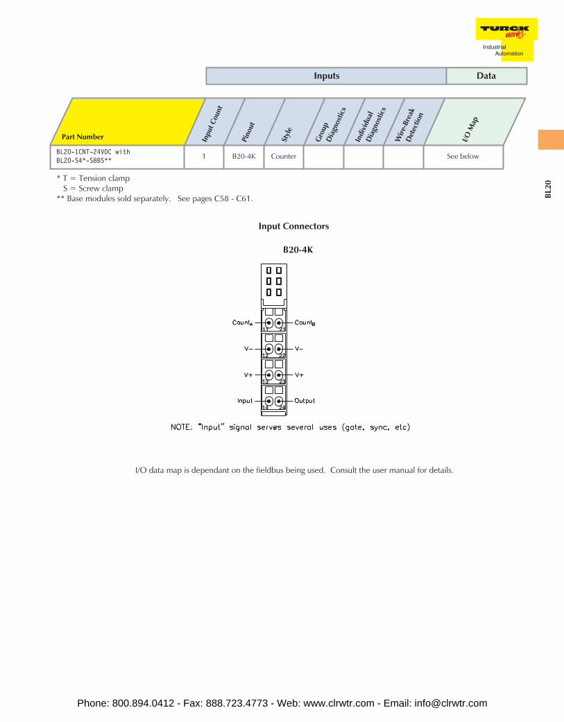
BL20-1CNT-24VDC withBL20-S4*-SBBS** 1 B20-4K Counter See below
* T = Tension clampS = Screw clamp
** Base modules sold separately. See pages C58 - C61.
Inputs Data
B20-4K
I/O data map is dependant on the fieldbus being used. Consult the user manual for details.
Input Connectors
Phone: 800.894.0412 - Fax: 888.723.4773 - Web: www.clrwtr.com - Email: [email protected]

BL20-PF-120/230VAC-DBL20-PF-24VDC-D
Power Feeding Modules • Modular I/O• Fieldbus Independent Configuration
• IP 20 Protection• Supply AC or DC I/O Power
Electrical• Operating Current: <28 mA (from VMB)• Output Current: <10 A for downstream I/O
Power Distribution• Accepts AC (...120/230VAC...) or DC (...24VDC...) supply to provide VIO for
downstream modules
Mechanical• Operating Temperature: 0 to +55°C (+32 to +131°F)• Protection: IP 20
Diagnostics (Logical)• Diagnostic information available through the fieldbus gateway
Diagnostics (Physical)• LED to indicate module bus communication and power supply status.
Phone: 800.894.0412 - Fax: 888.723.4773 - Web: www.clrwtr.com - Email: [email protected]
BL20
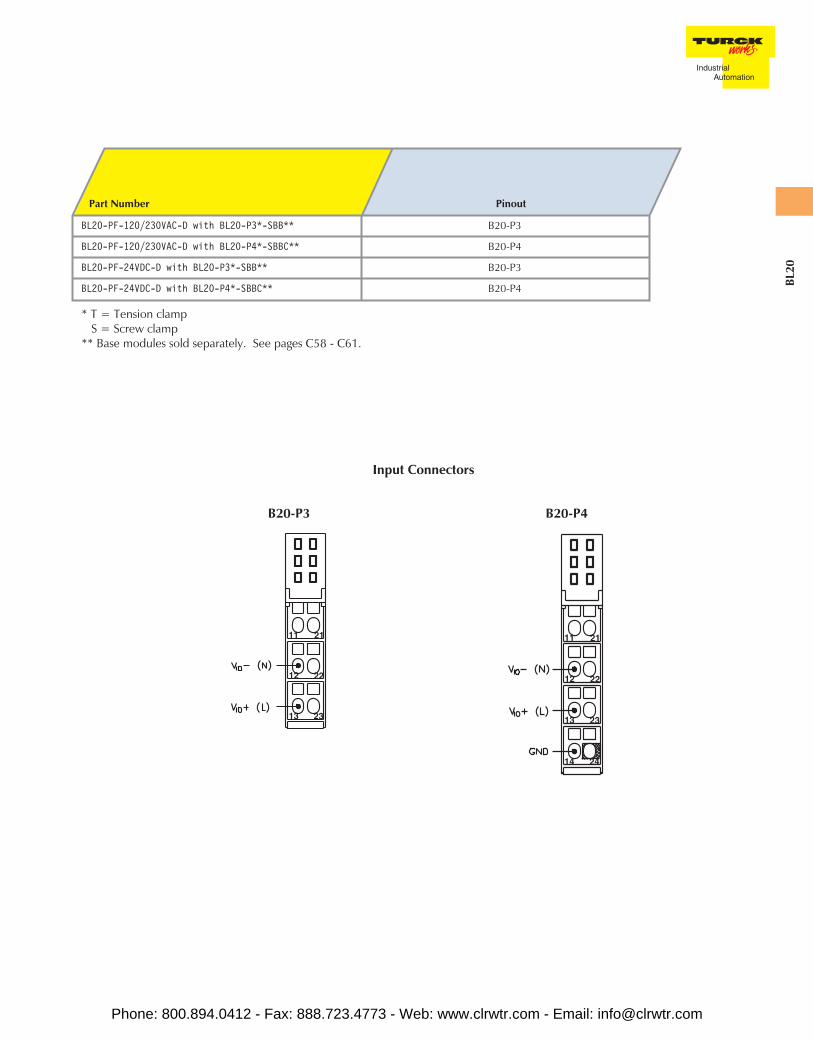
B20-P3
Part Number Pinout
BL20-PF-120/230VAC-D with BL20-P3*-SBB** B20-P3
BL20-PF-120/230VAC-D with BL20-P4*-SBBC** B20-P4
BL20-PF-24VDC-D with BL20-P3*-SBB** B20-P3
BL20-PF-24VDC-D with BL20-P4*-SBBC** B20-P4
* T = Tension clampS = Screw clamp
** Base modules sold separately. See pages C58 - C61.
B20-P4
Input Connectors
Phone: 800.894.0412 - Fax: 888.723.4773 - Web: www.clrwtr.com - Email: [email protected]
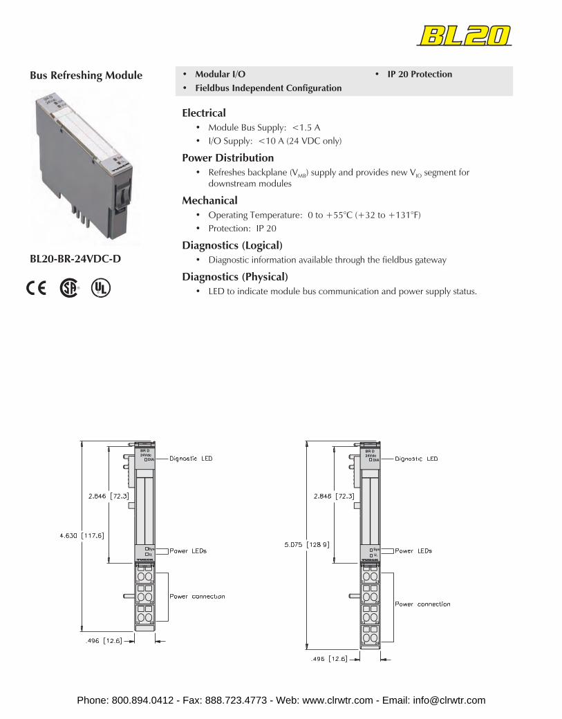
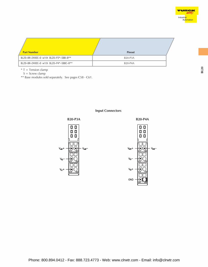
BL20-BR-24VDC-D
Bus Refreshing Module • Modular I/O• Fieldbus Independent Configuration
• IP 20 Protection
Electrical• Module Bus Supply: <1.5 A• I/O Supply: <10 A (24 VDC only)
Power Distribution• Refreshes backplane (VMB) supply and provides new VIO segment for
downstream modules
Mechanical• Operating Temperature: 0 to +55°C (+32 to +131°F)• Protection: IP 20
Diagnostics (Logical)• Diagnostic information available through the fieldbus gateway
Diagnostics (Physical)• LED to indicate module bus communication and power supply status.
Phone: 800.894.0412 - Fax: 888.723.4773 - Web: www.clrwtr.com - Email: [email protected]
BL20
B20-P3A B20-P4A
Part Number Pinout
BL20-BR-24VDC-D with BL20-P3*-SBB-B** B20-P3A
BL20-BR-24VDC-D with BL20-P4*-SBBC-B** B20-P4A
* T = Tension clampS = Screw clamp
** Base modules sold separately. See pages C58 - C61.
Input Connectors
Phone: 800.894.0412 - Fax: 888.723.4773 - Web: www.clrwtr.com - Email: [email protected]
Each gateway can support up to 3 SWIRE modules for a total of 48 non-reversing motor starters on a single gateway. Anyreversing motor starter is considered as 2 non-reversing. The motor starters are rated for .06kW to 15kW (0.08hp to 20hp).
By ordering parts of the motor starter separately will allow for fewer parts to be stored within your inventory and will costless to repair if just one piece of the motor starter fails. Motor starters are hot-swappable as long as the SWIRE-DIL modulestays connected to the SWIRE system.
Refer to the user manual for details on installing and configuring the BL20 motor starter system.
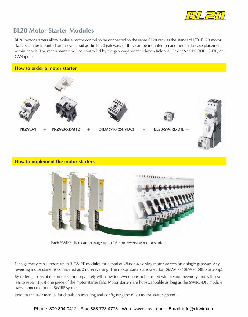
BL20 Motor Starter ModulesBL20 motor starters allow 3-phase motor control to be connected to the same BL20 rack as the standard I/O. BL20 motorstarters can be mounted on the same rail as the BL20 gateway, or they can be mounted on another rail to ease placementwithin panels. The motor starters will be controlled by the gateways via the chosen fieldbus (DeviceNet, PROFIBUS-DP, orCANopen).
How to implement the motor starters
Each SWIRE slice can manage up to 16 non-reversing motor starters.
How to order a motor starter
+ BL20-SWIRE-DIL =PKZM0-1 + PKZM0-XDM12 + DILM7-10 (24 VDC)
Phone: 800.894.0412 - Fax: 888.723.4773 - Web: www.clrwtr.com - Email: [email protected]
BL20
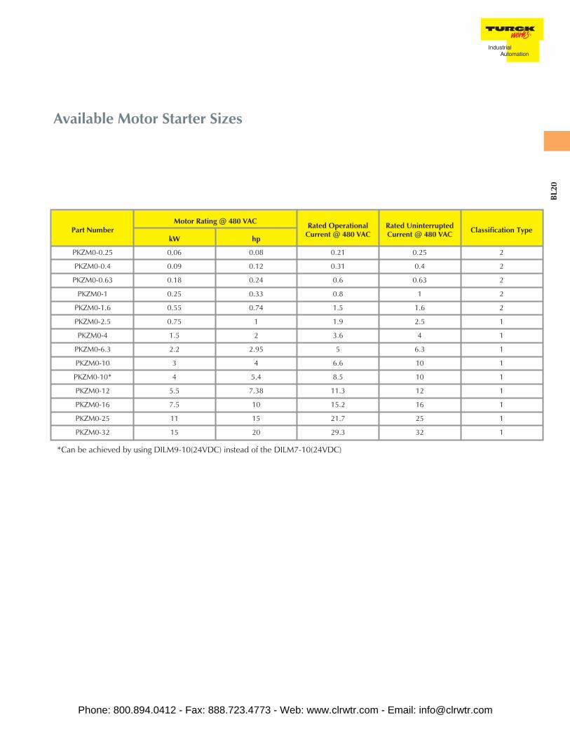
Available Motor Starter Sizes
Part NumberMotor Rating @ 480 VAC Rated Operational
Current @ 480 VACRated UninterruptedCurrent @ 480 VAC Classification Type
kW hp
PKZM0-0.25 0.06 0.08 0.21 0.25 2
PKZM0-0.4 0.09 0.12 0.31 0.4 2
PKZM0-0.63 0.18 0.24 0.6 0.63 2
PKZM0-1 0.25 0.33 0.8 1 2
PKZM0-1.6 0.55 0.74 1.5 1.6 2
PKZM0-2.5 0.75 1 1.9 2.5 1
PKZM0-4 1.5 2 3.6 4 1
PKZM0-6.3 2.2 2.95 5 6.3 1
PKZM0-10 3 4 6.6 10 1
PKZM0-10* 4 5.4 8.5 10 1
PKZM0-12 5.5 7.38 11.3 12 1
PKZM0-16 7.5 10 15.2 16 1
PKZM0-25 11 15 21.7 25 1
PKZM0-32 15 20 29.3 32 1
*Can be achieved by using DILM9-10(24VDC) instead of the DILM7-10(24VDC)
Phone: 800.894.0412 - Fax: 888.723.4773 - Web: www.clrwtr.com - Email: [email protected]

hp Motor Contactor Part Number Wiring Set PartNumber Relay Part Number SWIRE
Communication
0.08 PKZM0-0.25
PKZM0-XDM12
DILM7-10(24 VDC)
BL20-SWIRE-DIL
0.12 PKZM0-0.4
0.24 PKZM0-0.63
0.33 PKZM0-1
0.74 PKZM0-1.6
1 PKZM0-2.5
2 PKZM0-4
2.95 PKZM0-6.3
4 PKZM0-10
5.4 PKZM0-10* DILM9-10(24 VDC)
7.38 PKZM0-12 DILM12-10(24 VDC)
10 PKZM0-16 DILM15-10(24 VDC)
15 PKZM0-25PKZM0-XDM32
DILM25-10(24 VDC)
20 PKZM0-32 DILM32-10(24 VDC)
* To order a motor starter with the rated hp, order one of each part number that appears to the right.
Non-Reversing Part Numbers
Phone: 800.894.0412 - Fax: 888.723.4773 - Web: www.clrwtr.com - Email: [email protected]
BL20
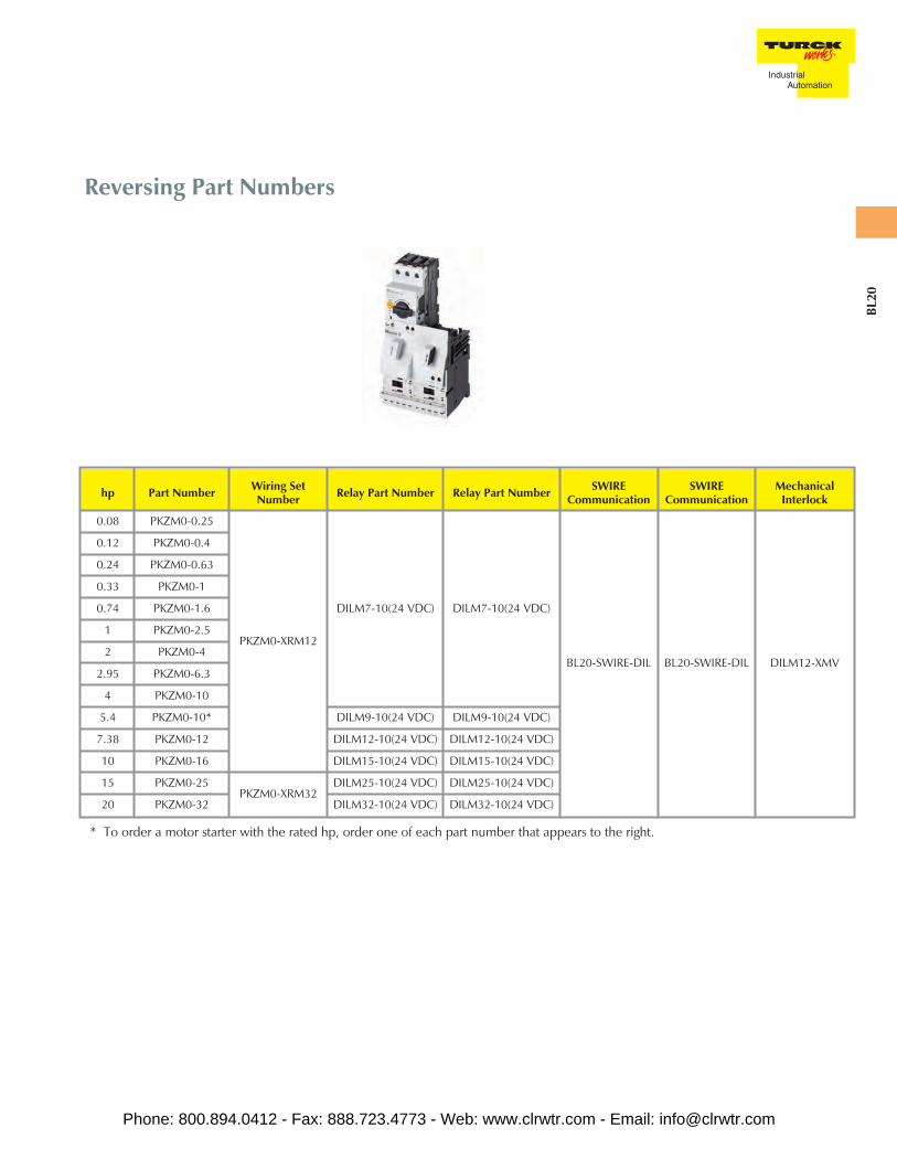
Reversing Part Numbers
hp Part Number Wiring SetNumber Relay Part Number Relay Part Number SWIRE
CommunicationSWIRE
CommunicationMechanical
Interlock
0.08 PKZM0-0.25
PKZM0-XRM12
DILM7-10(24 VDC) DILM7-10(24 VDC)
BL20-SWIRE-DIL BL20-SWIRE-DIL DILM12-XMV
0.12 PKZM0-0.4
0.24 PKZM0-0.63
0.33 PKZM0-1
0.74 PKZM0-1.6
1 PKZM0-2.5
2 PKZM0-4
2.95 PKZM0-6.3
4 PKZM0-10
5.4 PKZM0-10* DILM9-10(24 VDC) DILM9-10(24 VDC)
7.38 PKZM0-12 DILM12-10(24 VDC) DILM12-10(24 VDC)
10 PKZM0-16 DILM15-10(24 VDC) DILM15-10(24 VDC)
15 PKZM0-25PKZM0-XRM32
DILM25-10(24 VDC) DILM25-10(24 VDC)
20 PKZM0-32 DILM32-10(24 VDC) DILM32-10(24 VDC)
* To order a motor starter with the rated hp, order one of each part number that appears to the right.
Phone: 800.894.0412 - Fax: 888.723.4773 - Web: www.clrwtr.com - Email: [email protected]
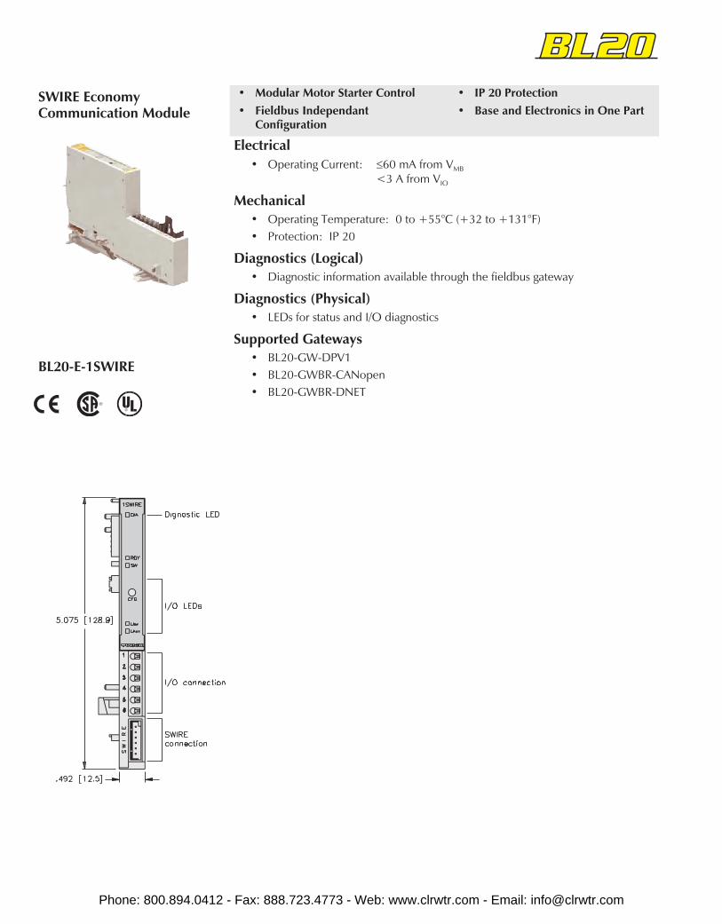
• Modular Motor Starter Control• Fieldbus Independant
Configuration
• IP 20 Protection• Base and Electronics in One Part
SWIRE EconomyCommunication Module
BL20-E-1SWIRE
Electrical• Operating Current: ≤60 mA from VMB
<3 A from VIO
Mechanical• Operating Temperature: 0 to +55°C (+32 to +131°F)• Protection: IP 20
Diagnostics (Logical)• Diagnostic information available through the fieldbus gateway
Diagnostics (Physical)• LEDs for status and I/O diagnostics
Supported Gateways• BL20-GW-DPV1• BL20-GWBR-CANopen• BL20-GWBR-DNET
Phone: 800.894.0412 - Fax: 888.723.4773 - Web: www.clrwtr.com - Email: [email protected]
BL20
Part Number Inpu
t Cou
nt
Pino
ut
Curr
ent
Gro
upD
iagn
ostic
s
Indi
vidu
alD
iagn
ostic
s
Wire
-Bre
akD
etec
tion
I/OM
ap
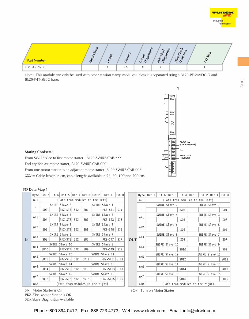
BL20-E-1SWIRE 1 3 A X X 1
Note: This module can only be used with other tension clamp modules unless it is separated using a BL20-PF-24VDC-D andBL20-P4T-SBBC base.
OUT
Byte Bit 7 Bit 6 Bit 5 Bit 4 Bit 3 Bit 2 Bit 1 Bit 0
n-1 (Data from modules to the left)
nSWIRE Slave 2 SWIRE Slave 1
SO2 SO1
n+1SWIRE Slave 4 SWIRE Slave 3
SO4 SO3
n+2SWIRE Slave 6 SWIRE Slave 5
SO6 SO5
n+3SWIRE Slave 8 SWIRE Slave 7
SO8 SO7
n+4SWIRE Slave 10 SWIRE Slave 9
SO10 SO9
n+5SWIRE Slave 12 SWIRE Slave 11
SO12 SO11
n+6SWIRE Slave 14 SWIRE Slave 13
SO14 SO13
n+7SWIRE Slave 16 SWIRE Slave 15
SO16 SO15
n+8 (Data from modules to the right)
SOx: Turn on Motor Starter
In
Byte Bit 7 Bit 6 Bit 5 Bit 4 Bit 3 Bit 2 Bit 1 Bit 0
n-1 (Data from modules to the left)
nSWIRE Slave 2 SWIRE Slave 1
SD2 PKZ-ST2 SI2 SD1 PKZ-ST1 SI1
n+1SWIRE Slave 4 SWIRE Slave 3
SD4 PKZ-ST2 SI2 SD3 PKZ-ST3 SI3
n+2SWIRE Slave 6 SWIRE Slave 5
SD6 PKZ-ST2 SI2 SD5 PKZ-ST5 SI5
n+3SWIRE Slave 8 SWIRE Slave 7
SD8 PKZ-ST2 SI2 SD7 PKZ-ST7 SI7
n+4SWIRE Slave 10 SWIRE Slave 9
SD10 PKZ-ST2 SI2 SD9 PKZ-ST9 SI9
n+5SWIRE Slave 12 SWIRE Slave 11
SD12 PKZ-ST2 SI2 SD11 PKZ-ST11 SI11
n+6SWIRE Slave 14 SWIRE Slave 13
SD14 PKZ-ST2 SI2 SD13 PKZ-ST13 SI13
n+7SWIRE Slave 16 SWIRE Slave 15
SD16 PKZ-ST2 SI2 SD15 PKZ-ST15 SI15
n+8 (Data from modules to the right)
SIx: Motor Starter is OnPKZ-STx: Motor Starter is OKSDx:Slave Diagnostics Available
I/O Data Map 1
1
Mating Cordsets:
From SWIRE slice to first motor starter: BL20-SWIRE-CAB-XXX.
End cap for last motor starter; BL20-SWIRE-CAB-000
From one motor starter to an adjacent motor starter: BL20-SWIRE-CAB-008
XXX = Cable length in cm, cable lengths available in 25, 50, 100 and 200 cm.
Phone: 800.894.0412 - Fax: 888.723.4773 - Web: www.clrwtr.com - Email: [email protected]
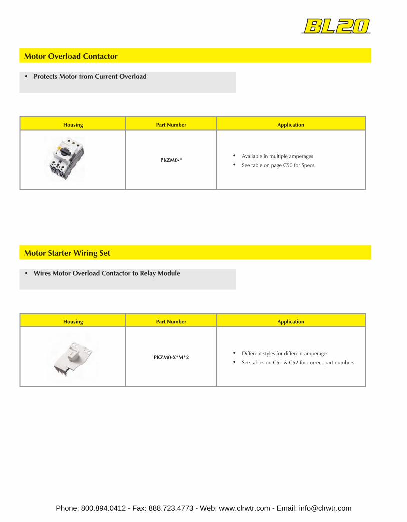
• Wires Motor Overload Contactor to Relay Module
Motor Starter Wiring Set
Housing Part Number Application
PKZM0-X*M*2• Different styles for different amperages
• See tables on C51 & C52 for correct part numbers
• Protects Motor from Current Overload
Motor Overload Contactor
Housing Part Number Application
PKZM0-*• Available in multiple amperages
• See table on page C50 for Specs.
Phone: 800.894.0412 - Fax: 888.723.4773 - Web: www.clrwtr.com - Email: [email protected]
BL20
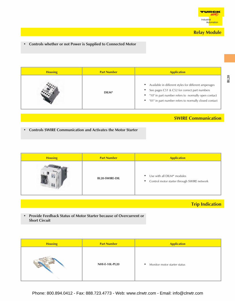
• Controls SWIRE Communication and Activates the Motor Starter
SWIRE Communication
Housing Part Number Application
BL20-SWIRE-DIL• Use with all DILM* modules
• Control motor starter through SWIRE network
Trip Indication
• Provide Feedback Status of Motor Starter because of Overcurrent orShort Circuit
Housing Part Number Application
NHI-E-10L-PL20 • Monitor motor starter status
• Controls whether or not Power is Supplied to Connected Motor
Relay Module
Housing Part Number Application
DILM*
• Available in different styles for different amperages
• See pages C51 & C52 for correct part numbers
• "10" in part number refers to normally open contact
• "01" in part number refers to normally closed contact
Phone: 800.894.0412 - Fax: 888.723.4773 - Web: www.clrwtr.com - Email: [email protected]
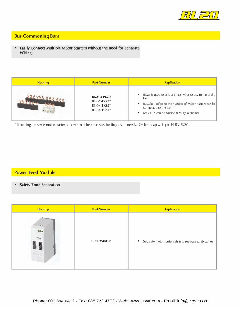
Power Feed Module
• Safety Zone Separation
Housing Part Number Application
BL20-SWIRE-PF • Separate motor starter sets into separate safety zones
• Easily Connect Multiple Motor Starters without the need for SeparateWiring
Bus Commoning Bars
Housing Part Number Application
BK25/3-PKZ0B3.0/2-PKZ0*B3.0/4-PKZ0*B3.0/5-PKZ0*
• BK25 is used to land 3 phase wires to beginning of thebus
• B3.0/x; x refers to the number of motor starters can beconnected to the bar
• Max 63A can be carried through a bus bar
* If bussing a reverse motor starter, a cover may be necessary for finger safe needs. Order a cap with p/n H-B3-PKZ0.
Phone: 800.894.0412 - Fax: 888.723.4773 - Web: www.clrwtr.com - Email: [email protected]
BL20
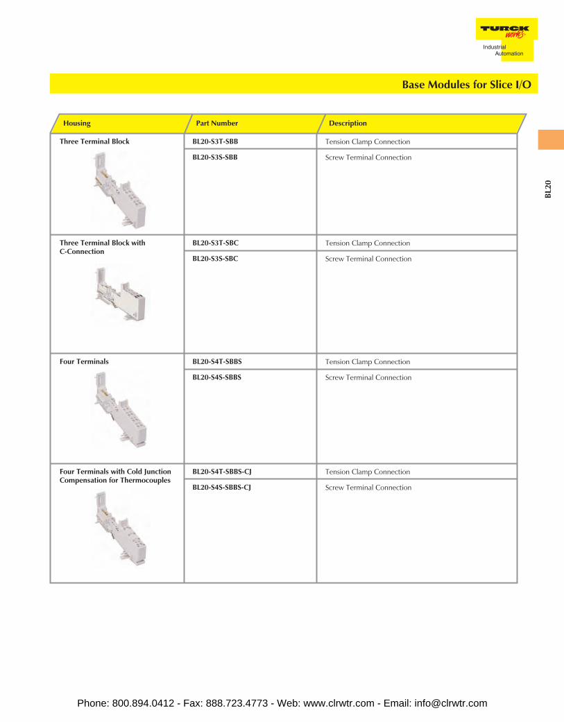
Base Modules for Slice I/O
Housing Part Number Description
Three Terminal Block BL20-S3T-SBB Tension Clamp Connection
BL20-S3S-SBB Screw Terminal Connection
Three Terminal Block withC-Connection
BL20-S3T-SBC Tension Clamp Connection
BL20-S3S-SBC Screw Terminal Connection
Four Terminals BL20-S4T-SBBS Tension Clamp Connection
BL20-S4S-SBBS Screw Terminal Connection
Four Terminals with Cold JunctionCompensation for Thermocouples
BL20-S4T-SBBS-CJ Tension Clamp Connection
BL20-S4S-SBBS-CJ Screw Terminal Connection
Phone: 800.894.0412 - Fax: 888.723.4773 - Web: www.clrwtr.com - Email: [email protected]

Base Modules for Slice I/O
Housing Part Number Description
Four Terminals with C-Connection BL20-S4T-SBBC Tension Clamp Connection
BL20-S4S-SBBC Screw Terminal Connection
Four Terminals with C-Connection,Dual Signal
BL20-S4T-SBCS Tension Clamp Connection
BL20-S4S-SBCS Screw Terminal Connection
Six Terminals BL20-S6T-SBBSBB Tension Clamp Connection
BL20-S6S-SBBSBB Screw Terminal Connection
Six Terminals with C-Connection BL20-S6T-SBCSBC Tension Clamp Connection
BL20-S6S-SBCSBC Screw Terminal Connection
Phone: 800.894.0412 - Fax: 888.723.4773 - Web: www.clrwtr.com - Email: [email protected]
BL20
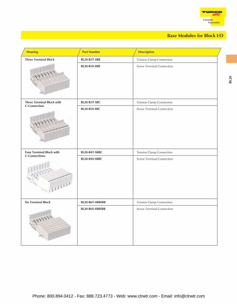
Housing Part Number Description
Three Terminal Block BL20-B3T-SBB Tension Clamp Connection
BL20-B3S-SBB Screw Terminal Connection
Three Terminal Block withC-Connection
BL20-B3T-SBC Tension Clamp Connection
BL20-B3S-SBC Screw Terminal Connection
Four Terminal Block withC-Connections
BL20-B4T-SBBC Tension Clamp Connection
BL20-B4S-SBBC Screw Terminal Connection
Six Terminal Block BL20-B6T-SBBSBB Tension Clamp Connection
BL20-B6S-SBBSBB Screw Terminal Connection
Base Modules for Block I/O
Phone: 800.894.0412 - Fax: 888.723.4773 - Web: www.clrwtr.com - Email: [email protected]
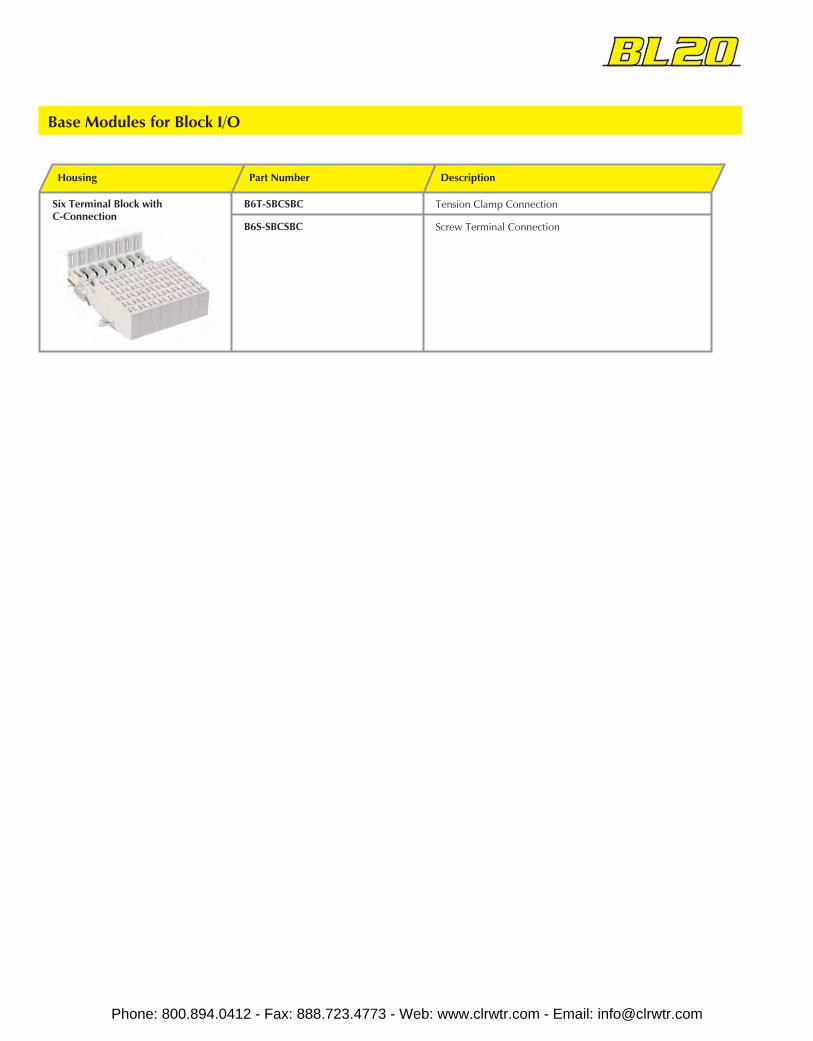
Housing Part Number Description
Six Terminal Block withC-Connection
B6T-SBCSBC Tension Clamp Connection
B6S-SBCSBC Screw Terminal Connection
Base Modules for Block I/O
Phone: 800.894.0412 - Fax: 888.723.4773 - Web: www.clrwtr.com - Email: [email protected]
BL20
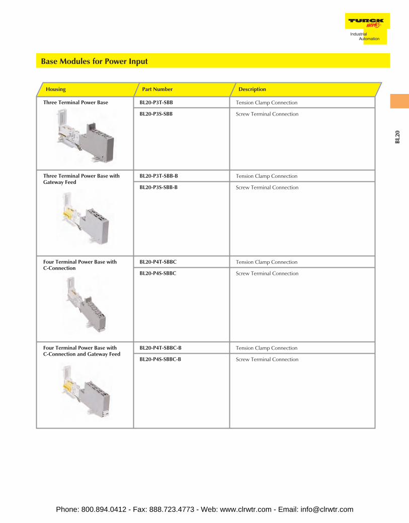
Housing Part Number Description
Three Terminal Power Base BL20-P3T-SBB Tension Clamp Connection
BL20-P3S-SBB Screw Terminal Connection
Three Terminal Power Base withGateway Feed
BL20-P3T-SBB-B Tension Clamp Connection
BL20-P3S-SBB-B Screw Terminal Connection
Four Terminal Power Base withC-Connection
BL20-P4T-SBBC Tension Clamp Connection
BL20-P4S-SBBC Screw Terminal Connection
Four Terminal Power Base withC-Connection and Gateway Feed
BL20-P4T-SBBC-B Tension Clamp Connection
BL20-P4S-SBBC-B Screw Terminal Connection
Base Modules for Power Input
Phone: 800.894.0412 - Fax: 888.723.4773 - Web: www.clrwtr.com - Email: [email protected]

Housing Part Number Description
MarkersUsed for color coding terminals onBL20 base modules
XN-ANBZ-WS (10/PKG)XN-ANBZ-GN/GE/BED (10/PKG)XN-ANBZ-RT/BL-BED (10/PKG)XN-ANBZ-BR (10/PKG)XN-ANBZ-SW (10/PKG)XN-ANBZ-GN (10/PKG)XN-ANBZ-RT (10/PKG)XN-ANBZ-BL (10/PKG)
WhiteGreen/YellowRed/BlueBrownBlackGreenRedBlue
JumpersFor use with BL20 relay modules
XN-QV/8 (10/PKG)XN-QV/7 (10/PKG)XN-QV/6 (10/PKG)XN-QV/5 (10/PKG)XN-QV/4 (10/PKG)XN-QV/3 (10/PKG)XN-QV/2 (10/PKG)XN-QV/1 (10/PKG)
8 pair7 pair6 pair5 pair4 pair3 pair2 pair1 pair
Coding BlocksFor keying electronic modules tobase modules
XN-KO/17 (10/PKG)XN-KO/16 (10/PKG)XN-KO/14 (10/PKG)XN-KO/13 (10/PKG)XN-KO/12 (10/PKG)
XN-KO/11 (10/PKG)XN-KO/10 (10/PKG)XN-KO/9 (10/PKG)XN-KO/8 (10/PKG)XN-KO/6 (10/PKG)XN-KO/2 (10/PKG)
BL20-PF-120/230VAC-DBL20-PF-24VDC-DBL20-2AO-U(-10/0...+10V)BL20-1AO-I(0/4...20MA)RTD and TC temperature modules,BL20-1AI-U(-10/0...+10V)BL20-1AI-I(0/4...20MA)BL20-2DO-R-COBL20-2DO-R-NCBL20-2DO-R-NOBL20-*DO-24VDC*BL20-*DI-24VDC*
Phone: 800.894.0412 - Fax: 888.723.4773 - Web: www.clrwtr.com - Email: [email protected]

BL20
Housing Part Number Description
Labels FW5/151-200 (10 SETS/PKG)FW5/101-150 (10 SETS/PKG)FW5/51-100 (10 SETS/PKG)FW5/1-50 (10 SETS/PKG)
Numbered 151-200Numbered 101-150Numbered 51-100Numbered 1-50
End Bracket XN-WEW-35/2-SW (1/PKG)
End Plate XN-ABPL
Shield Connection - For use with analog modules XN-KLBU/S (10/PKG)XN-KLBU/T (10/PKG)
Screw terminalTension clamp
Labels - For labeling electronic modules. DIN A5 sheets BL20-LABEL/BLOCK (5 SHEETS/PKG)BL20-LABEL/SCHEIBE (5 SHEETS/PKG)
For block modulesFor slice modules
Tension Clamp Tool - For ease of operating tension clampconnections
ZBW5-2
Ferrite Ring - For damping high frequency inteference on dataand supply lines
PS416-ZBX-405 (2/PKG)
Shield Connection - For use with direct wiring gateways SCH-1-WINBLOC (1/PKG)
Programming Cable - For connecting the BL20/BL67 system tothe I/O Assistant software
XN-PS2-CABLE
Phone: 800.894.0412 - Fax: 888.723.4773 - Web: www.clrwtr.com - Email: [email protected]