Embed Size (px)
Citation preview

RMP/RMC-14-6 Serpentine Build Service Manual Update If you have any further questions or concerns regarding this service manual update please contact RigMaster Power’s
Technical Support Department at (888) 208-3101 before proceeding with service or repairs.
Introduction to the Serpentine Drive System 1.1 Installation of the Auto-Tensioner 1.2 Remove/Replace Flywheel Pulley 1.3 Installation of the Idle Pulley 1.4 Remove/Replace Serpentine Belt 1.5 Engine Enclosure Parts 1.6 Engine Vibration Mounts and Shock Pads 1.7 Generator Mounting 1.8 Air Conditioning Specifications 1.9 Air Conditioning System Hoses and Components 1.10 Remove/Replace the High Efficiency Compressor 1.11 Integrated Straight Muffler with Reversible End Caps 1.12 Remove and Replace the Integrated Straight Muffler 1.13 Engine Wiring Harness 1.14 1.1 Introduction to the Serpentine Drive System RigMaster APU’s starting with the following serial numbers (and higher) are equipped with a serpentine belt that drives the 120 Volt generator and high efficiency air conditioning compressor from the flywheel of the engine:
RMP-14-6-14372 (Perkins Build) RMC-14-6-00972 (Caterpillar Build)
Figure 1-1
Belt Auto-Tensioner Assembly
Idler Pulley Assembly
Flywheel Pulley Assembly

RMP/RMC-14-6 Serpentine Build Service Manual Update If you have any further questions or concerns regarding this service manual update please contact RigMaster Power’s
Technical Support Department at (888) 208-3101 before proceeding with service or repairs.
1.2 Installation of the Auto-Tensioner
WARNING The auto tensioner unit is not serviceable. Do not attempt to disassemble the auto
tensioner as severe injury may result. The auto-tensioner is mounted to the engine using the auto tensioner mounting bracket.
1. The auto-tensioner bracket is to be installed
on the flywheel back plate, with the upper mounting point (1) sharing a mounting bolt with the starter motor (Figure 1-4).
2. The lower point (2) is bolted to the flywheel
back plate 3. Hold the auto-tensioner assembly to the
mounting bracket and slide the long bolt through the washer, tensioner and bracket point (3).
4. Secure the tensioner to the bracket with a
washer, and nylon lock nut
Auto Tensioner Mounting Bracket RP8-107
Auto Tensioner RP8-106
13 Figure 1-2
2
Figure 1-3
Figure 1-4
3 Auto
Tensioner
12
Starter Motor

RMP/RMC-14-6 Serpentine Build Service Manual Update If you have any further questions or concerns regarding this service manual update please contact RigMaster Power’s
Technical Support Department at (888) 208-3101 before proceeding with service or repairs.
1.3 Remove/Replace Flywheel Pulley Ensure that the flywheel and flywheel pulley adapter are clean and free of any debris prior to installation; this will ensure that the drive pulley is properly aligned.
Figure 1-5 1
2 3
Figure 1-6
Pulley Adapter RP8-102
1. Align the drive pulley adapter with the three point pattern on the flywheel
2. Install the mounting hardware and
torque to 37 ft. lbs (50.5 N·m).
Figure 1-7
Pulley RP8-103
3. Align the drive pulley with the three point pattern on the flywheel adapter.
4. Install the mounting hardware and
torque to 37 ft. lbs (50.5 N·m).

RMP/RMC-14-6 Serpentine Build Service Manual Update If you have any further questions or concerns regarding this service manual update please contact RigMaster Power’s
Technical Support Department at (888) 208-3101 before proceeding with service or repairs.
1.4 Installation of the Idle Pulley
Figure 1-8
Engine Flywheel
Idler Pulley Mounting Point
y 101].
gine.
k nut.
Idler Pulley Standoff Washer
Figure 1-9 1. Insert the long bolt through the washer, idle pulley standoff washer [RP8-105], and idler pulle[RP8-
2. Slide the bolt through the idle pulley standoff [RP8-104] and insert it into the flywheel back plate on the en
3. On the rear of the flywheel back plate, install the washer and secure the assembly with the nylon loc
Idler Pulley Standoff
Figure 1-10 Figure 1-11

RMP/RMC-14-6 Serpentine Build Service Manual Update If you have any further questions or concerns regarding this service manual update please contact RigMaster Power’s
Technical Support Department at (888) 208-3101 before proceeding with service or repairs.
1.5 Remove/Replace Serpentine Belt
2008 model RMP and RMC 14-6 RigMaster APU’s incorporate a serpentine belt and auto tensioner system to drive the air conditioning compressor and the 120 Volt AC generator from the flywheel at the back of the engine. A v-belt drives the alternator and water pump and engine fan from the crank pulley on the front side of the engine (this belt system has not been modified).
# Component Part Number
1 Drive Pulley Adapter RP8-100 1 Drive Pulley RP8-101 2 Generator Pulley RP8-102 3 Idle Pulley RP8-103 3 Idle Pulley Standoff RP8-104 3 Idle Pulley Standoff washer RP8-105 4 Auto Tensioner RP8-106 4 Tensioner Bracket RP8-107 5 Serpentine Belt RP8-108
SERVICE INTERVAL Every 1000 engine operating hours inspect the serpentine belt and change if necessary. Please note that the use of conditioner may extend the service life of belts; consult the belt manufacturer for more information on belt maintenance.
Figure 1-12
4 1 5
2 3

RMP/RMC-14-6 Serpentine Build Service Manual Update If you have any further questions or concerns regarding this service manual update please contact RigMaster Power’s
Technical Support Department at (888) 208-3101 before proceeding with service or repairs.
Section 1.5 Continued…
1. Remove engine cover 2. Insert breaker bar or ratchet into serpentine belt auto-tensioner as shown in figure 1-
13 (recommended method).
3. Lift the breaker bar to release tension on the serpentine belt. 4. Remove belt from flywheel pulley while holding tensioner. 5. Release tensioner and remove belt. 6. Replace belt as shown in figure 1-1. 7. Ensure that the belt is properly seated on all pulleys before starting the engine.
CAUTION You may also use an open ended wrench (Figure 1-14), but be sure to protect the
radiator in the event that the wrench slips.
CAUTION After changing the belt, but before starting the engine, see that the air conditioning
compressor and 120 Volt generator bolts are properly fastened.
Figure 1-16
Serpentine Drive Belt RP8-108
Figure 1-15
Figure 1-13 Figure 1-14

RMP/RMC-14-6 Serpentine Build Service Manual Update If you have any further questions or concerns regarding this service manual update please contact RigMaster Power’s
Technical Support Department at (888) 208-3101 before proceeding with service or repairs.
RIGMASTER POWER APPROVED CROSS REFERENCE PARTS LIST RMP and RMC 14-6 with Serpentine Drive System
OIL FILTER AIR FILTER
BRAND
PART No.
BRAND
PART No.
AC Delco PF1233 Perkins 140516250 RigMaster/Mann 00-C1140
Wix 51396 K-Mart Motorvator K014477 AIR FILTER ASSEMBLY Fram PH4386 Baldwin B37 RigMaster 103002
FUEL FILTER FAN BELT
BRAND
PART No.
BRAND
PART No.
Wix 33262 RigMaster RP8-009 NAPA 3262 Bando 2310 9.5 X 790LA Perkins 130366040 Perkins 080109049 Fram C7516 Baldwin PF937 AC Delco GF771
SERPENTINE DRIVE BELT GLOW PLUGS
BRAND PART No. BRAND PART No.
RigMaster RP8-108 Dayco 535K6 Metric Dimensions 6PK1360
Perkins 185366220
RECEIVER-DRIER
BRAND PART No.
RigMaster RP9-027 Four Seasons 34334 Everco (UAP) A78239
THE USE OF SERVICE COMPONENTS NOT LISTED IN THIS
TABLE MAY CAUSE DAMAGE TO THE ASSEMBLY AND/OR VOID THE
MANUFACTURERS’ WARRANTY

RMP/RMC-14-6 Serpentine Build Service Manual Update If you have any further questions or concerns regarding this service manual update please contact RigMaster Power’s
Technical Support Department at (888) 208-3101 before proceeding with service or repairs.
1.6 Engine Enclosure Parts
Figure 1-17
Please note that components may not be exactly as shown

RMP/RMC-14-6 Serpentine Build Service Manual Update If you have any further questions or concerns regarding this service manual update please contact RigMaster Power’s
Technical Support Department at (888) 208-3101 before proceeding with service or repairs.
Enclosure Parts Table (Refer to Figure 1-17)
# Description of Frame Component Part Number
1 Cover Buttons RP10-001-12 2 Engine Cover RP10-001-18K 2 Optional Engine Cover (Stainless Steel) RP10-001-SSK 3 LH Condenser Cover RP10-001-43A 4 LH Side Panel RP10-001-50 5 Frame RP10-001-1A 6 Generator Cover RP10-001-31 7 LH Mounting Bracket RP10-001-57 8 RH Mounting Bracket RP10-001-56 9 Generator Cover Plugs RP12-097
10 RH Side Panel RP10-001-48 11 Oil Quick Access Hatch Cover RP10-001-32 12 Bottom Plate RP10-001-35 13 LH Engine Stiffener RP10-001-4 14 RH Engine Stiffener RP10-001-2 15 Front Engine Mount Plate RP10-001-33 16 Rear Engine Mount Plate RP10-001-34 17 Cover Latches RP12-056
Not Shown 120V Generator Junction Box Lid RP10-001-25 Not Shown 120V Generator Junction Box RP10-001-36 1.7 Engine Vibration Mounts and Shock Pads
4
3
2
5
1
Top View of Frame
Figure 1-18
Counting each location in Figure 1-18 there are a total of:
(5) Blue Dot vibration mounts
[RP11-002]
and
(5) Shock Pads [RP11-003]

RMP/RMC-14-6 Serpentine Build Service Manual Update If you have any further questions or concerns regarding this service manual update please contact RigMaster Power’s
Technical Support Department at (888) 208-3101 before proceeding with service or repairs.
Figure 1-19 A: Shock Pad B: Engine Mount Fasteners C: Engine Mount Plate D: Oversized 3/8” Flat Washer E: Centre Mount bolt ⅜”-16X2½” F: ⅜”-16 Nut G: ⅜” Lock Washer H: Blue Dot Vibration Mount
Side View
Figure 1-20
Figure 1-22 Figure 1-23
Compressor Mount Plate RP10-001-33
Figure 1-21
Generator Mount Plate RP10-001-34

RMP/RMC-14-6 Serpentine Build Service Manual Update If you have any further questions or concerns regarding this service manual update please contact RigMaster Power’s
Technical Support Department at (888) 208-3101 before proceeding with service or repairs.
1.8 Generator Mounting
Location LEGEND QTY.
A Captive Nut 2 B Generator Mounting Flange N/A C Hold Down Bolts 4 D Flat Washers 6 E Lock Washer 2 F 6000 Watt 120 Volt AC. Generator 1 G Nylon Lock Nut 2 H Generator/Engine Mounting Plate 1
Figure 1-24
Figure 1-25 Figure 1-25
Figure 1-26

RMP/RMC-14-6 Serpentine Build Service Manual Update If you have any further questions or concerns regarding this service manual update please contact RigMaster Power’s
Technical Support Department at (888) 208-3101 before proceeding with service or repairs.
1.9 Air Conditioning Specifications AIR CONDITIONING SPECIFICATIONS Refrigerant Type R134a Volume of Refrigerant 1.9 lbs; 30.5 oz; 0.86 Kg Compressor Oil Type SP-46 PAG Compressor Oil Compressor Oil Volume (pre-filled new) 6.0 fl oz; 177 cc; 177 ml 1.10 Air Conditioning System Hoses and Components
Figure 1-27
LEGEND PRESSURE Part Number
A Condenser High RP9-011 B Compressor High/Low RP9-129 C Receiver Dryer High RP9-027 D Evaporator High RP9-201 E Evaporator Core Temperature Probe High/Low RP9-113 F Bulkhead Section of Frame N/A RP10-001-1A G Evaporator to Bulkhead High RP9-404 H Evaporator to Bulkhead Low RP9-405 I Receiver Dryer to Bulkhead High RP9-403 J Compressor to Bulkhead Low RP9-401 K Condenser to Receiver Dryer High RP9-402 L Compressor to Condenser High RP9-400 M Expansion Valve High/Low RP9-112

RMP/RMC-14-6 Serpentine Build Service Manual Update If you have any further questions or concerns regarding this service manual update please contact RigMaster Power’s
Technical Support Department at (888) 208-3101 before proceeding with service or repairs.
1.11 Remove/Replace the High Efficiency Compressor This compressor does not pivot and the belt is automatically tensioned when installed correctly.
1. Remove the serpentine belt. 2. Disconnect the wiring harness (A). 3. Evacuate the refrigerant (B) (there are Schrader ports on the compressor). 4. Remove the high and low pressure lines from the manifold (C). 5. Remove the four mounting bolts, flat washers and lock-washers (D). 6. Remove and replace the compressor, torque the mounting bolts to 37 ft. lbs (50.5
N·m). 7. Inspect and reinstall the serpentine belt (see 1.5), replace the belt if it is
damaged. 8. Reinstall the high and low pressure hoses. 9. Reconnect the wiring harness. 10. Vacuum and recharge – pressure test if a leak is suspected. 11. Start the APU and test the air conditioning.
Figure 1-28
D DC
A
B
D D
WARNING Exercise caution when removing protective caps from the #10 and #8 ports as the compressor may be under pressure. Wear safety glasses and cover the ports with a shop rag prior to removal of the protective caps.

RMP/RMC-14-6 Serpentine Build Service Manual Update If you have any further questions or concerns regarding this service manual update please contact RigMaster Power’s
Technical Support Department at (888) 208-3101 before proceeding with service or repairs.
Figure 1-29
Compressor Clutch Pulley
Engine Mounts
Figure 1-30
Low Pressure Port # 10
Low Pressure Schrader Valve
High Pressure Port # 8
High Pressure Schrader Valve
A: Hex Head Mounting Bolt B: Lock Washer C: Flat Washer
Figure 1-32 Figure 1-31
ABC

RMP/RMC-14-6 Serpentine Build Service Manual Update If you have any further questions or concerns regarding this service manual update please contact RigMaster Power’s
Technical Support Department at (888) 208-3101 before proceeding with service or repairs.
1.12 Integrated Straight Muffler with Reversible End Caps
RigMaster APU’s starting with the following serial numbers (and higher) are equipped with an integrated straight muffler.
RMP-14-6-14568 (Perkins Build)
he integrated straight muffler [RP6-009] is fully interchangeable with the integrated oval aster RMP/RMC 14-6 units. Additionally, the straight muffler
hangeable to redirect the
o reverse the end caps: m each end cap
-36 and 1-37) and switch their
RMC-14-6-01014 (Caterpillar Build) Tmuffler [RP6-007] on RigMhas flexible exhausting options as the end caps are intercengine exhaust out of the front or rear of the assembly. T1. Remove the four hex head crews fro2. Remove the end 3. Reinstall the hex head screws
caps (Figure 1 positions
Removable Open-End Cap Removable Closed-End Cap
RP6-009
Figure 1-33
Figure 1-35
Figure 1-36 Figure 1-37
Figure 1-34

RMP/RMC-14-6 Serpentine Build Service Manual Update If you have any further questions or concerns regarding this service manual update please contact RigMaster Power’s
Technical Support Department at (888) 208-3101 before proceeding with service or repairs.
NOTE
Extension pipe/elbow (solid pipe, not flex pipe) can be added to the exhaust system to direct the exhaust away from the sleeper. A maximum of 10 feet including the muffler can be added to the exhaust system without creating a harmful back pressure. See that any extension pipe is securely fastened.
The 45° exhaust tip is not a required component in this exhaust system, and may be removed in the event that extension tail pipe must be added (see NOTE above).
Figure 1-38
45° Exhaust Tip
1.13 Remove and Replace the Integrated Straight Muffler
1. Remove the clamp inside the engine compartment that secures the exhaust flex to the exhaust pipe.
2. Remove the hardware that secures the muffler to bulkhead and the underside of the frame
3. Remove the muffler 4. Assembly is the reverse of disassembly
1.14 Engine Wiring Harness
NOTE The RP7-069 wiring harness is also used in the RMP T4-6 model RigMaster units. When installed on a 14-6 model RigMaster there will be some portions of the harness that are not used. The additional points are for connecting the DPF filter kit on T4-6 model RigMaster’s. The 14-6 model is not compatible with the DPF filter kit and should not make use of the optional connection points. The wiring harness on the RMP/RMC 14-6 model RigMaster’s has been redesigned and is listed under the part number RP7-069. The following schematic (Figure 1-39) is available as a high resolution document located under “manuals and support material” on the customer access side of the RigMaster website or by contacting technical support.

RMP/RMC-14-6 Serpentine Build Service Manual Update If you have any further questions or concerns regarding this service manual update please contact RigMaster Power’s
Technical Support Department at (888) 208-3101 before proceeding with service or repairs.
Figure 1-39
RMP/RMC-14-6 Serpentine Build Service Manual Update If you have any further questions or concerns regarding this service manual update please contact RigMaster Power’s
Technical Support Department at (888) 208-3101 before proceeding with service or repairs.
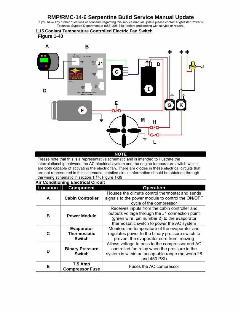
1.15 Coolant Temperature Controlled Electric Fan Switch Figure 1-40
NOTE
Please note that this is a representative schematic and is intended to illustrate the interrelationship between the AC electrical system and the engine temperature switch which are both capable of activating the electric fan. There are diodes in these electrical circuits that are not represented in this schematic; detailed circuit information should be obtained through the wiring schematic in section 1.14, Figure 1-39
Air Conditioning Electrical Circuit Location Component Operation
A Cabin Controller Houses the climate control thermostat and sends
signals to the power module to control the ON/OFF cycle of the compressor
B Power Module Receives inputs from the cabin controller and
outputs voltage through the J1 connection point (green wire, pin number 2) to the evaporator thermostatic switch to power the AC system
C Evaporator
Thermostatic Switch
Monitors the temperature of the evaporator and regulates power to the binary pressure switch to
prevent the evaporator core from freezing
D Binary Pressure Switch
Allows voltage to pass to the compressor and AC controlled fan relay when the pressure in the
system is within an acceptable range (between 28 and 450 PSI)
E 7.5 Amp Compressor Fuse Fuses the AC compressor

RMP/RMC-14-6 Serpentine Build Service Manual Update If you have any further questions or concerns regarding this service manual update please contact RigMaster Power’s
Technical Support Department at (888) 208-3101 before proceeding with service or repairs.
Continued from 1.15 Location Component Operation
F Compressor Receives its power from the binary switch through 7.5 amp in-line fuse
G AC Controlled Fan Relay
Receives its signal from the binary pressure switch when energized and ensures the electric fan runs
when the compressor is active
H 35 Amp Electric Fan Fuse Fuses the electric fan
I Receiver/Dryer Removes moisture from the refrigerant Engine Temperature Switch Circuit
J Coolant
Temperature Switch
Outputs signal voltage to the engine temperature controlled fan relay when the engine reaches
195°F
K Engine
Temperature Controlled Fan
Relay
Receives its signal from the coolant temperature switch ensuring that the electric fan operates when
engine temperature rises above the switches threshold.
L 35 Amp Electric Fan Fuse Fuses the electric fan
M Electric Fan Cools the radiator and/or the condenser
Figure 1-41 Figure 1-42 Electric Fan Temperature Switch
• Switch is open under 195 °F • Switch is closed over 195 °F
Electric Fan Temperature Switch [RP7-214]
Water Pump
RMP/RMC-14-6 Serpentine Build Service Manual Update If you have any further questions or concerns regarding this service manual update please contact RigMaster Power’s
Technical Support Department at (888) 208-3101 before proceeding with service or repairs.
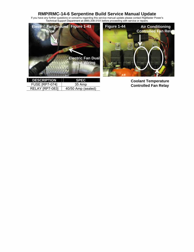
Figure 1-43 Figure 1-44 Electric Fan Ground Wire
Air Conditioning Controlled Fan Relay
Electric Fan Dual Input Wiring
DESCRIPTION SPEC FUSE [RP7-074] 35 Amp
RELAY [RP7-083] 40/50 Amp (sealed)
Coolant Temperature Controlled Fan Relay


![F] F] IYæ— F] ECO F] @ ) RMC-HP2K RMC-HP3KD/RMC-HP3K RMC-HP3 MITSIBISHI @ (Blffi)](https://img.pdfslide.net/doc/110x75/5ae590b77f8b9a8b2b8c0615/f-f-iy-f-eco-f-rmc-hp2k-rmc-hp3kdrmc-hp3k-rmc-hp3-mitsibishi-blffi.jpg)