Embed Size (px)
Citation preview
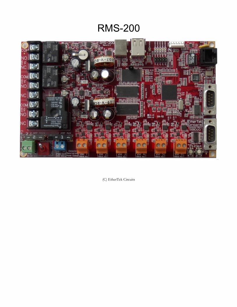
RMS-200
(C) EtherTek Circuits
O w n e r s M a n u a l
R E M O T E M O N I T O R I N G M A D E E A S Y !
RMS-200 Owners Manual (Rev 1a)July 15, 2010
EtherTek Circuits473 Corina Ave • Unit 38Princeton, B.C. Canada
V0X 1W0 • Phone 250.295.6794
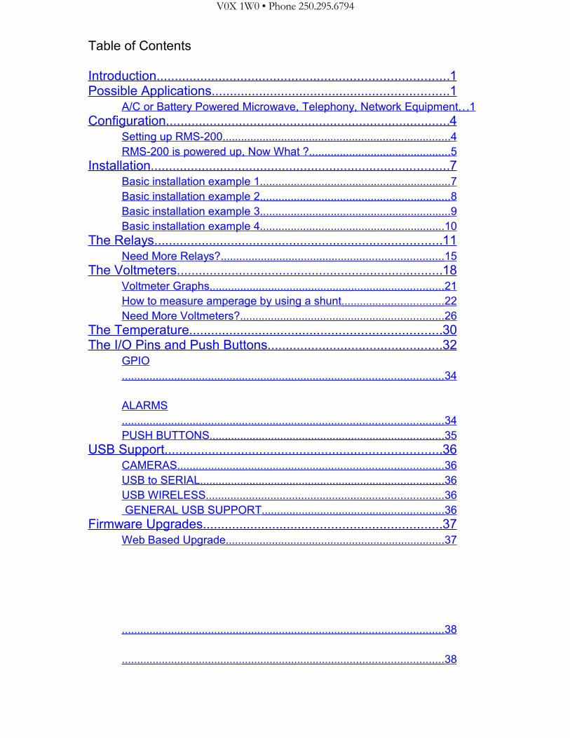
Table of Contents
Introduction ................................................................................ 1 Possible Applications ................................................................. 1
A/C or Battery Powered Microwave, Telephony, Network Equipment .. . 1 Configuration .............................................................................. 4
Setting up RMS-200 .......................................................................... 4 RMS-200 is powered up, Now What ? .............................................. 5
Installation .................................................................................. 7 Basic installation example 1 .............................................................. 7 Basic installation example 2 .............................................................. 8 Basic installation example 3 .............................................................. 9 Basic installation example 4 ............................................................ 10
The Relays ............................................................................... 11 Need More Relays? ........................................................................ 15
The Voltmeters ......................................................................... 18 Voltmeter Graphs ............................................................................ 21 How to measure amperage by using a shunt ................................. 22 Need More Voltmeters? .................................................................. 26
The Temperature ..................................................................... 30 The I/O Pins and Push Buttons ................................................ 32
GPIO ........................................................................................................ 34
ALARMS ........................................................................................................ 34 PUSH BUTTONS ............................................................................ 35
USB Support ............................................................................ 36 CAMERAS ...................................................................................... 36 USB to SERIAL ............................................................................... 36 USB WIRELESS ............................................................................. 36 GENERAL USB SUPPORT ........................................................... 36
Firmware Upgrades ................................................................. 37 Web Based Upgrade ....................................................................... 37
........................................................................................................ 38
........................................................................................................ 38

FTP Based Upgrade ....................................................................... 39
Downloads ............................................................................... 41 Specs ....................................................................................... 42
Base System 4Mb Flash / 16 Mb Ram ........................................... 42 General Board Information .............................................................. 42 Block Diagram ................................................................................. 43
Graphs ..................................................................................... 44 Warranty .................................................................................. 45
R E M O T E M O N I T O R I N G M A D E E A S Y !
Introduction
RMS-200 Is a unique remote monitoring, data acquisition, and control device specifically designed for use with Battery powered wireless internet repeater sites, or other AC & DC powered remote equipment
RMS-200 Has ultra low power consumption and won't put a drain on your power source. Uses less than 2 watts.
RMS-200 Is powered by DC voltage from 10 to 60 volts.
RMS-200 Uses embedded Ethernet technology for internet data acquisition and remote voltage monitoring.
RMS-200 Uses the LINUX operating system for versatility, stability, and security.
RMS-200 Gives you the situational awareness you need to keep your equipment operational and reliable.
Possible ApplicationsA/C or Battery Powered Microwave, Telephony, Network Equipment
Use RMS-200 to monitor battery levels, room temperature, signal strength (RSSI) on radios and more. RMS-200 has 6 onboard isolated voltmeters giving it the ability to measure DC voltage from -100 to +100 volts with 24 bit accuracy. RMS-200 also has 3 power relays giving it the unique ability to turn on/off devices remotely using an Internet connection. Use the power relays to remote start a generator. RMS-200 has 5 dedicated input pins used for door alarms or to monitor motion sensors. RMS-200 has a full featured serial port, control modems, cell phones, gsm modules, and other devices that use serial communication. RMS-200 has two USB 2.0 ports that supports several USB devices concurrently using a USB hub. Control USB cameras, store data on USB flash drives, control USB speakers etc. RMS-200 has input and output pins used to control your own custom devices. RMS-200 can alert you via email or SMS messages when your battery bank is low. RMS-200 has ping monitor software that allows you to monitor network devices and alert you to failure and possibly power cycle the device. Monitor all this information remotely over an Internet connection using an ordinary web browser. RMS-200 gives you direct hardware control of fans, lights, computers, cameras, modems, radios, etc... No more guessing what your battery levels are. No more wondering if your signal strengths are at an acceptable level. No more long drives to reset a fussy radio. Let RMS-200 do this all remotely via the Internet.
1
R E M O T E M O N I T O R I N G M A D E E A S Y !
Features• Six layer PCB with Nickel Immersion Gold plating and red solder mask.
• 400 - MHz Arm Processor (500 Mips !).
• 256 - megs of Nand Flash. Create and store custom applications.
• 64 - megs of SD-Ram.
• Dual Low Noise Switching Power Supplies accepts 8 - 60 vdc input. Can be powered directly from 12, 24, or 48 volt battery banks.
• Battery backed-up, real time clock.
• One onboard temperature sensor –25c +100c.
• Six 24 bit isolated voltmeters (+/- 100 VDC). Each voltmeter has its own 24 bit Delta Sigma ADC.
• Each voltmeter can be put into low voltage shunt mode (+/- 2 VDC).
• Two Power Relays for devices using 1 – 240v -5 amps AC/DC current.
• One Power Relay for devices using 1 – 240v -15 amps AC/DC current.
• Two programmable push buttons.
• Four general purpose I/O pins.
• Power output port, 5.0vdc (500ma).
• One full serial port for controlling cell phones, modems, etc.
• One console serial port.
• Two USB 2.0 ports for cameras, wireless clients, extra Ethernet, etc.
• Runs real Linux! 2.6.30 kernel.
• Send SMS messages, Email alerts, SNMP traps, Remote Syslog Messages.
• Ping watchdog, power cycle equipment after a set amount of ping timeouts.
• Command line utilities: ping, ftp, email, relays, etc.
• Flash new firmware over the internet.
• Hardware Watchdog Reset.
• Control RMS-200 via web page, telnet, ssh, or snmp.
• Full SNMP v1, v2, v3 support (default v3).
2
R E M O T E M O N I T O R I N G M A D E E A S Y !
• Supports external USB relays and voltmeters.
• Hardware is user accessible from files on the board.
• Make your own utilities and scripts to upload. (Bash, PHP, Python, Lua)
• Pluggable connectors for ease of use.
A partial list of programs and packages included:SQLlite v3 database, Telnet ,Drop Bear SSH, Light Http and Https Server, Pro FTP, Cron scheduling agent, Busy Box, PPP, Net SNMP, NanoCom, Easy Edit and Vi, Fping, SMTP email client, IPtables, Lrz and Lsz, Open SSL, Modbus Library, RRD Tool, USB Web Camera Support.
A programmers dream:RMS-200 comes with PHP, Python, and Lua. Make your own custom monitoring programs and upload them to the RMS-200 board, or create your own branded interface!
3
R E M O T E M O N I T O R I N G M A D E E A S Y !
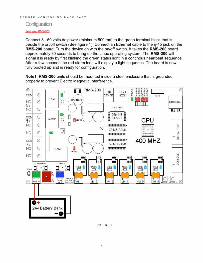
ConfigurationSetting up RMS-200
Connect 8 - 60 volts dc power (minimum 500 ma) to the green terminal block that is beside the on/off switch (See figure 1). Connect an Ethernet cable to the rj-45 jack on the RMS-200 board. Turn the device on with the on/off switch. It takes the RMS-200 board approximately 30 seconds to bring up the Linux operating system. The RMS-200 will signal it is ready by first blinking the green status light in a continous heartbeat sequence. After a few seconds the red alarm leds will display a light sequence. The board is now fully booted up and is ready for configuration.
Note1: RMS-200 units should be mounted inside a steel enclosure that is grounded properly to prevent Electro Magnetic Interference.
FIGURE 1
4
R E M O T E M O N I T O R I N G M A D E E A S Y !
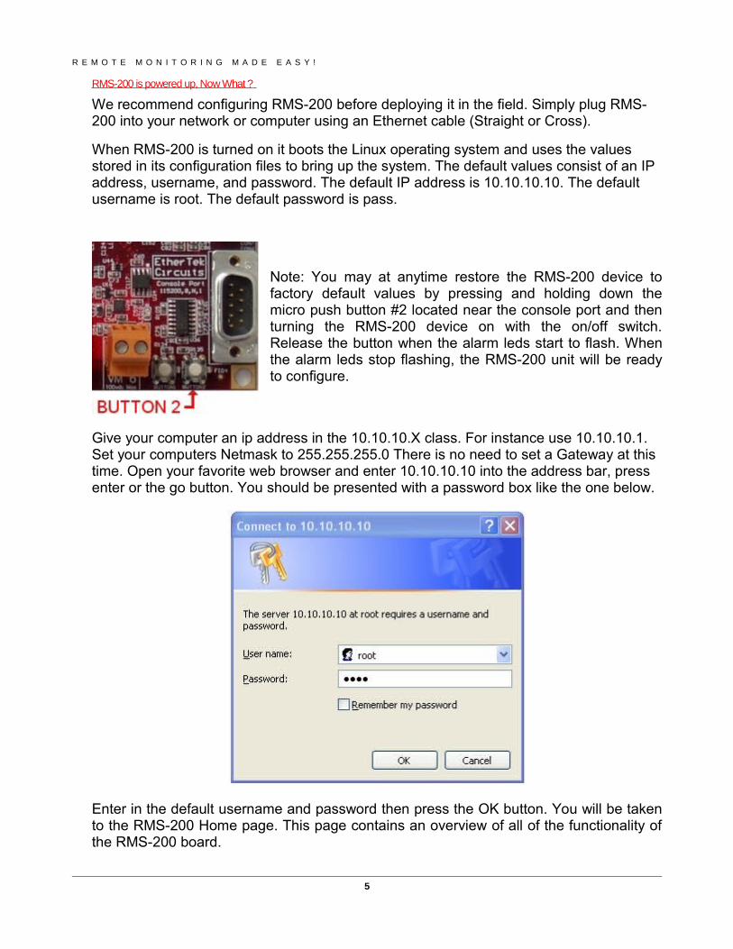
RMS-200 is powered up, Now What ?
We recommend configuring RMS-200 before deploying it in the field. Simply plug RMS-200 into your network or computer using an Ethernet cable (Straight or Cross).
When RMS-200 is turned on it boots the Linux operating system and uses the values stored in its configuration files to bring up the system. The default values consist of an IP address, username, and password. The default IP address is 10.10.10.10. The default username is root. The default password is pass.
Note: You may at anytime restore the RMS-200 device to factory default values by pressing and holding down the micro push button #2 located near the console port and then turning the RMS-200 device on with the on/off switch. Release the button when the alarm leds start to flash. When the alarm leds stop flashing, the RMS-200 unit will be ready to configure.
Give your computer an ip address in the 10.10.10.X class. For instance use 10.10.10.1. Set your computers Netmask to 255.255.255.0 There is no need to set a Gateway at this time. Open your favorite web browser and enter 10.10.10.10 into the address bar, press enter or the go button. You should be presented with a password box like the one below.
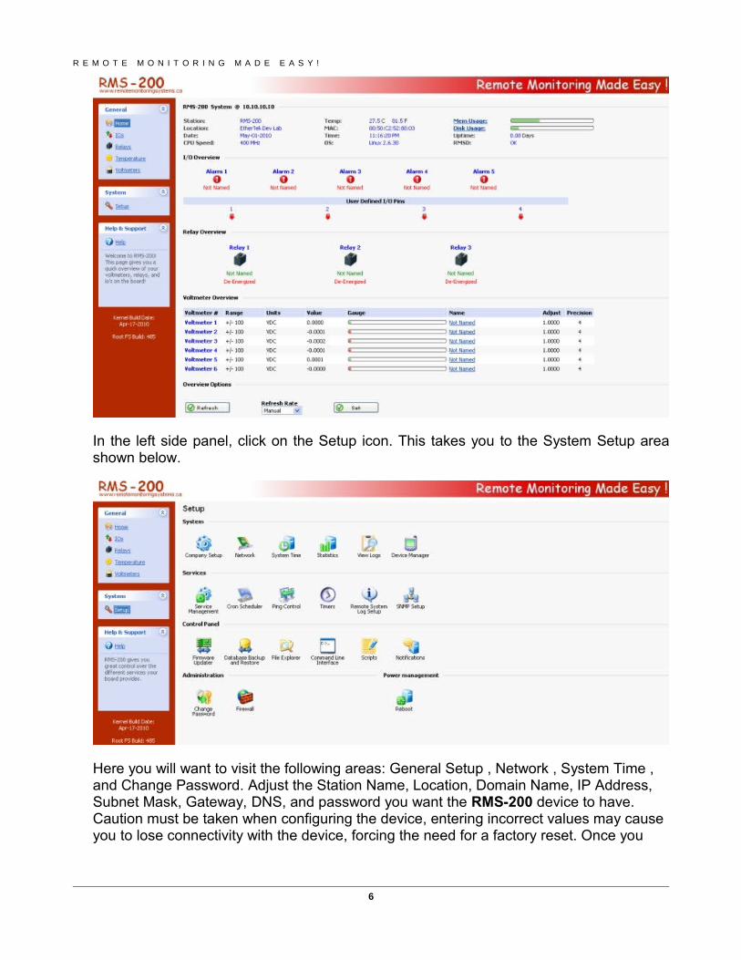
Enter in the default username and password then press the OK button. You will be taken to the RMS-200 Home page. This page contains an overview of all of the functionality of the RMS-200 board.
5
R E M O T E M O N I T O R I N G M A D E E A S Y !
In the left side panel, click on the Setup icon. This takes you to the System Setup area shown below.
Here you will want to visit the following areas: General Setup , Network , System Time , and Change Password. Adjust the Station Name, Location, Domain Name, IP Address, Subnet Mask, Gateway, DNS, and password you want the RMS-200 device to have. Caution must be taken when configuring the device, entering incorrect values may cause you to lose connectivity with the device, forcing the need for a factory reset. Once you
6
R E M O T E M O N I T O R I N G M A D E E A S Y !
have RMS-200 configured properly, it is ready to deploy in the field. Below are some basic examples of how to install the RMS-200 unit.
InstallationBasic installation example 1
Monitoring your Battery Bank
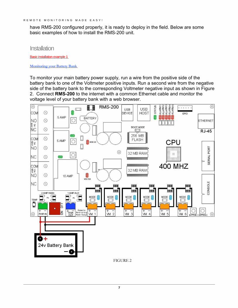
To monitor your main battery power supply, run a wire from the positive side of the battery bank to one of the Voltmeter positive inputs. Run a second wire from the negative side of the battery bank to the corresponding Voltmeter negative input as shown in Figure 2. Connect RMS-200 to the internet with a common Ethernet cable and monitor the voltage level of your battery bank with a web browser.
FIGURE 2
7
Basic installation example 2
Signal strength on Link CX Radios
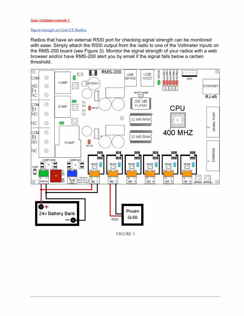
Radios that have an external RSSI port for checking signal strength can be monitored with ease. Simply attach the RSSI output from the radio to one of the Voltmeter inputs on the RMS-200 board (see Figure 3). Monitor the signal strength of your radios with a web browser and/or have RMS-200 alert you by email if the signal falls below a certain threshold.
FIGURE 3
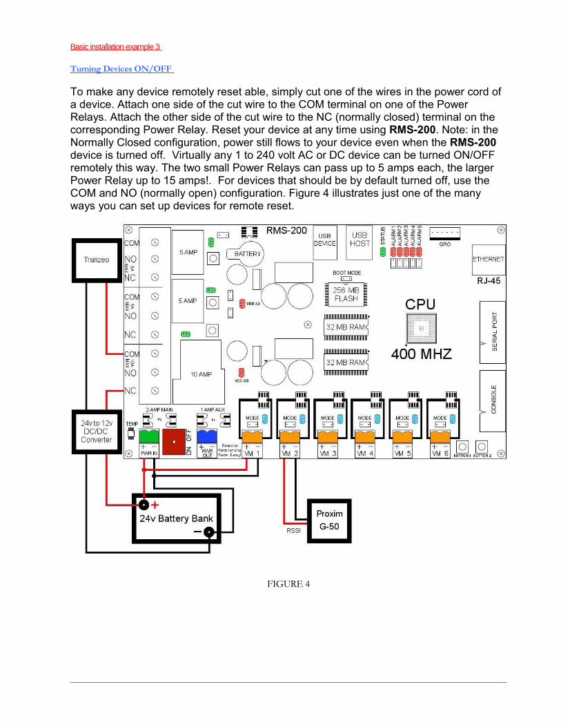
Basic installation example 3
Turning Devices ON/OFF
To make any device remotely reset able, simply cut one of the wires in the power cord of a device. Attach one side of the cut wire to the COM terminal on one of the Power Relays. Attach the other side of the cut wire to the NC (normally closed) terminal on the corresponding Power Relay. Reset your device at any time using RMS-200. Note: in the Normally Closed configuration, power still flows to your device even when the RMS-200 device is turned off. Virtually any 1 to 240 volt AC or DC device can be turned ON/OFF remotely this way. The two small Power Relays can pass up to 5 amps each, the larger Power Relay up to 15 amps!. For devices that should be by default turned off, use the COM and NO (normally open) configuration. Figure 4 illustrates just one of the many ways you can set up devices for remote reset.
FIGURE 4
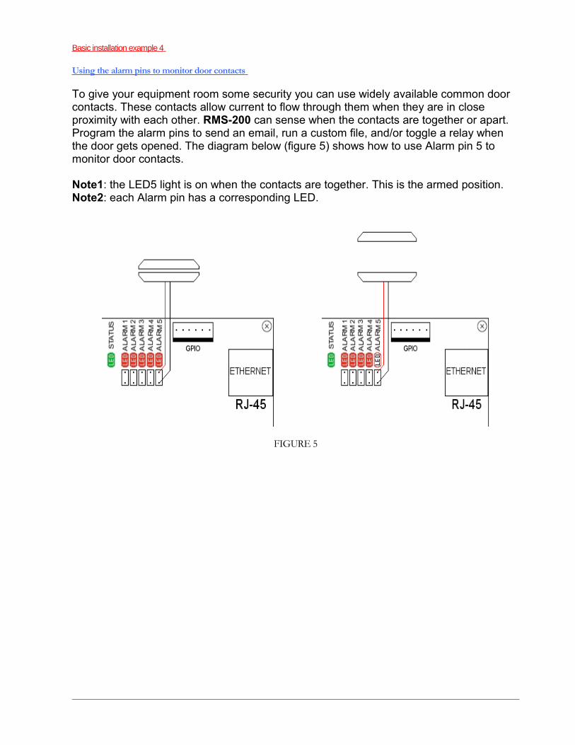
Basic installation example 4
Using the alarm pins to monitor door contacts
To give your equipment room some security you can use widely available common door contacts. These contacts allow current to flow through them when they are in close proximity with each other. RMS-200 can sense when the contacts are together or apart. Program the alarm pins to send an email, run a custom file, and/or toggle a relay when the door gets opened. The diagram below (figure 5) shows how to use Alarm pin 5 to monitor door contacts.
Note1: the LED5 light is on when the contacts are together. This is the armed position.Note2: each Alarm pin has a corresponding LED.
FIGURE 5
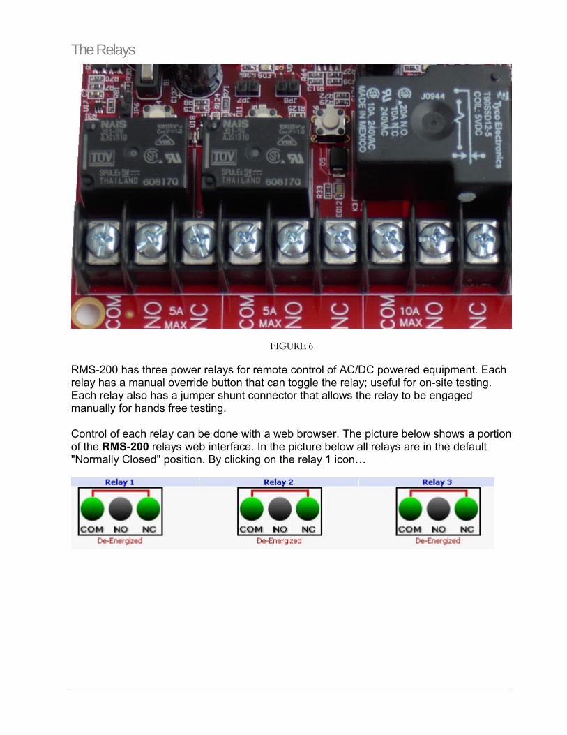
The Relays
FIGURE 6
RMS-200 has three power relays for remote control of AC/DC powered equipment. Each relay has a manual override button that can toggle the relay; useful for on-site testing. Each relay also has a jumper shunt connector that allows the relay to be engaged manually for hands free testing.
Control of each relay can be done with a web browser. The picture below shows a portion of the RMS-200 relays web interface. In the picture below all relays are in the default "Normally Closed" position. By clicking on the relay 1 icon…
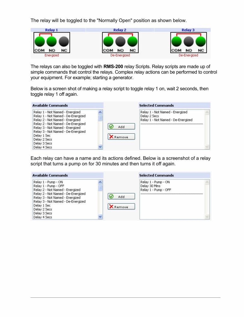
The relay will be toggled to the "Normally Open" position as shown below.
The relays can also be toggled with RMS-200 relay Scripts. Relay scripts are made up of simple commands that control the relays. Complex relay actions can be performed to control your equipment. For example; starting a generator.
Below is a screen shot of making a relay script to toggle relay 1 on, wait 2 seconds, then toggle relay 1 off again.
Each relay can have a name and its actions defined. Below is a screenshot of a relay script that turns a pump on for 30 minutes and then turns it off again.
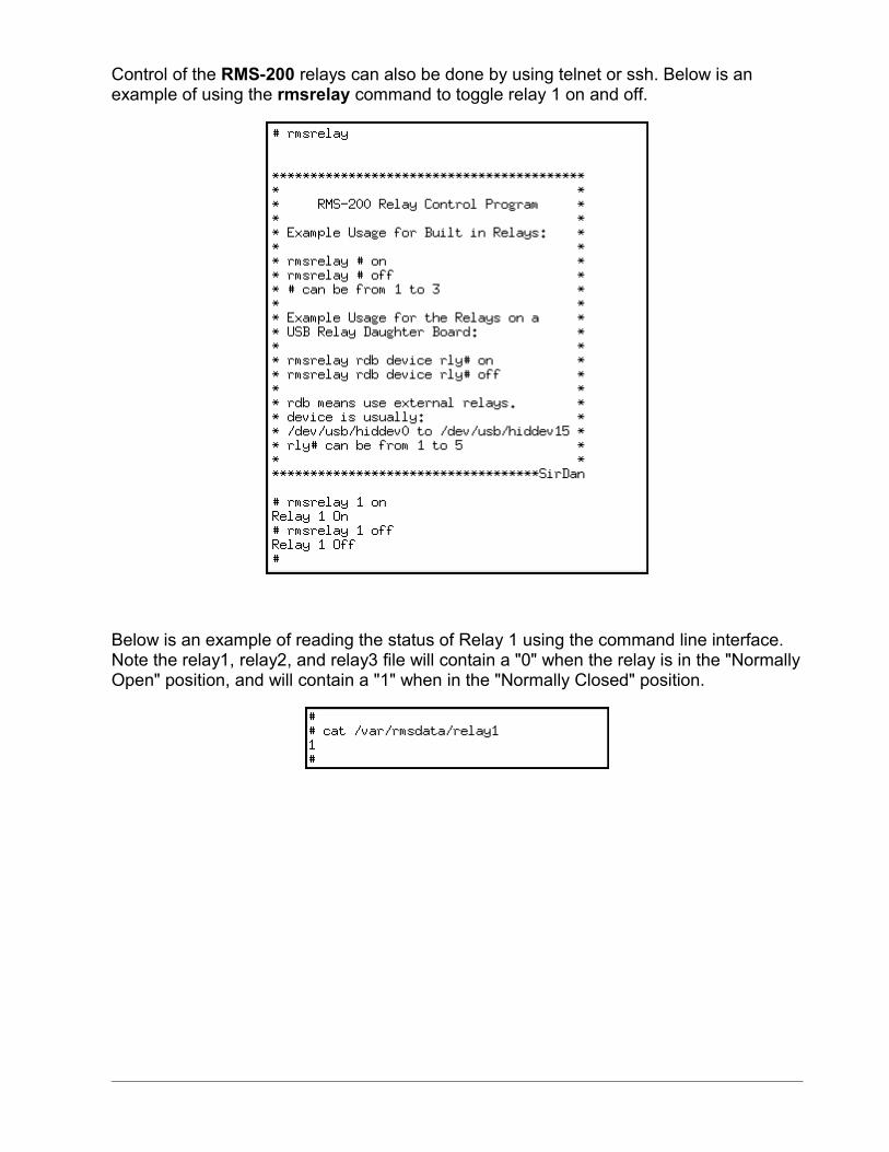
Control of the RMS-200 relays can also be done by using telnet or ssh. Below is an example of using the rmsrelay command to toggle relay 1 on and off.
Below is an example of reading the status of Relay 1 using the command line interface. Note the relay1, relay2, and relay3 file will contain a "0" when the relay is in the "Normally Open" position, and will contain a "1" when in the "Normally Closed" position.
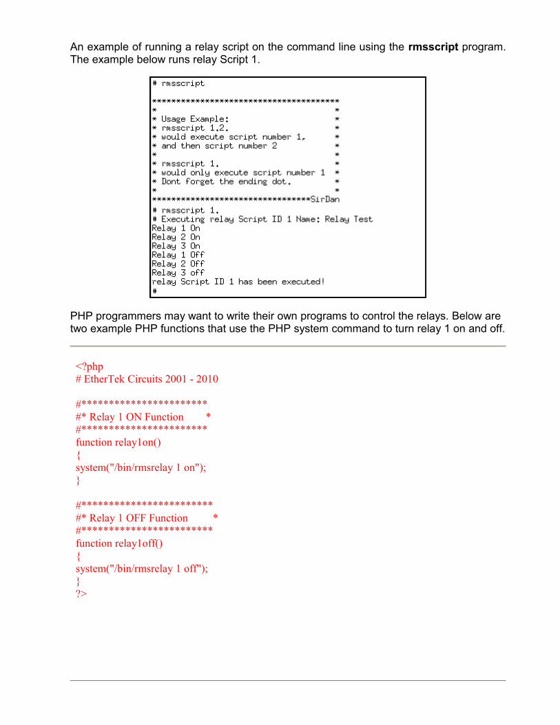
An example of running a relay script on the command line using the rmsscript program. The example below runs relay Script 1.
PHP programmers may want to write their own programs to control the relays. Below are two example PHP functions that use the PHP system command to turn relay 1 on and off.
<?php # EtherTek Circuits 2001 - 2010
#*********************** #* Relay 1 ON Function * #*********************** function relay1on() { system("/bin/rmsrelay 1 on"); } #************************ #* Relay 1 OFF Function * #************************ function relay1off() { system("/bin/rmsrelay 1 off"); } ?>
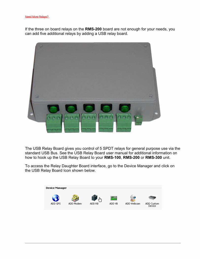
Need More Relays?
If the three on board relays on the RMS-200 board are not enough for your needs, you can add five additional relays by adding a USB relay board.
The USB Relay Board gives you control of 5 SPDT relays for general purpose use via the standard USB Bus. See the USB Relay Board user manual for additional information on how to hook up the USB Relay Board to your RMS-100, RMS-200 or RMS-300 unit.
To access the Relay Daughter Board interface, go to the Device Manager and click on the USB Relay Board Icon shown below.
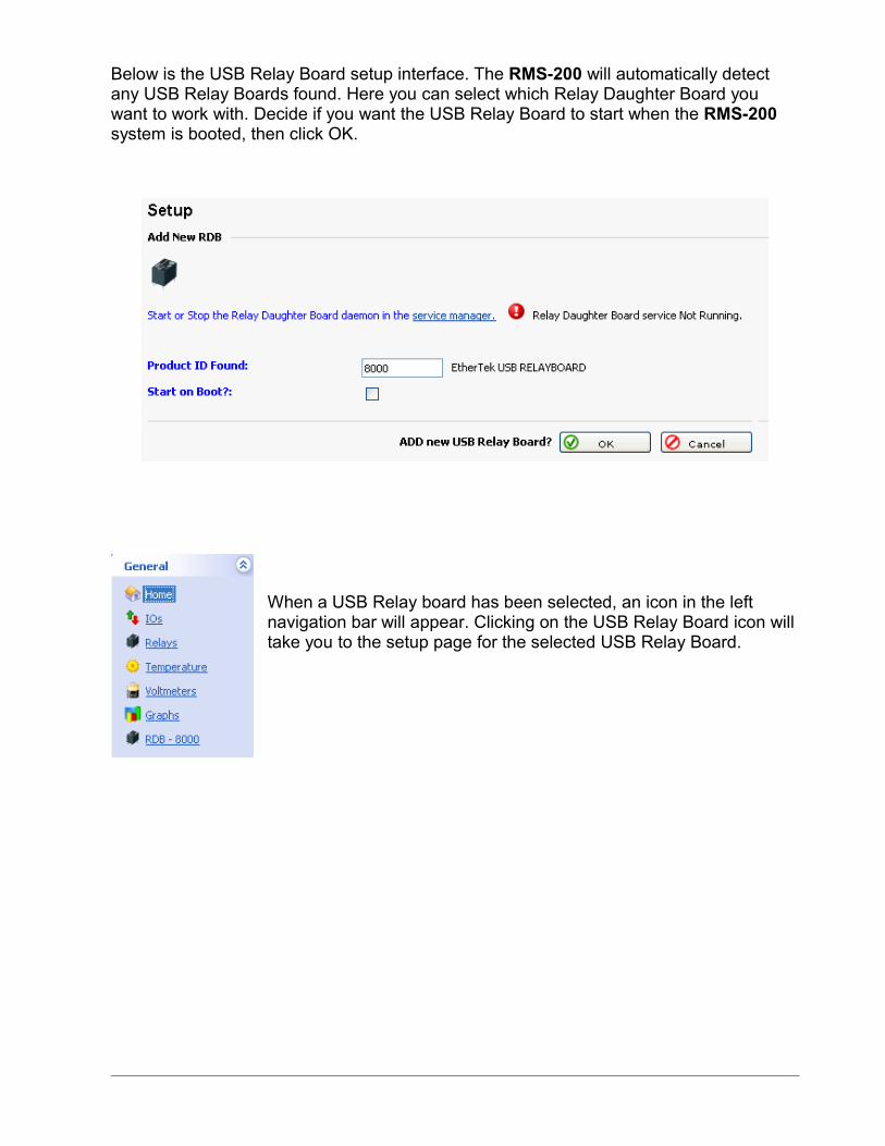
Below is the USB Relay Board setup interface. The RMS-200 will automatically detect any USB Relay Boards found. Here you can select which Relay Daughter Board you want to work with. Decide if you want the USB Relay Board to start when the RMS-200 system is booted, then click OK.
When a USB Relay board has been selected, an icon in the left navigation bar will appear. Clicking on the USB Relay Board icon will take you to the setup page for the selected USB Relay Board.
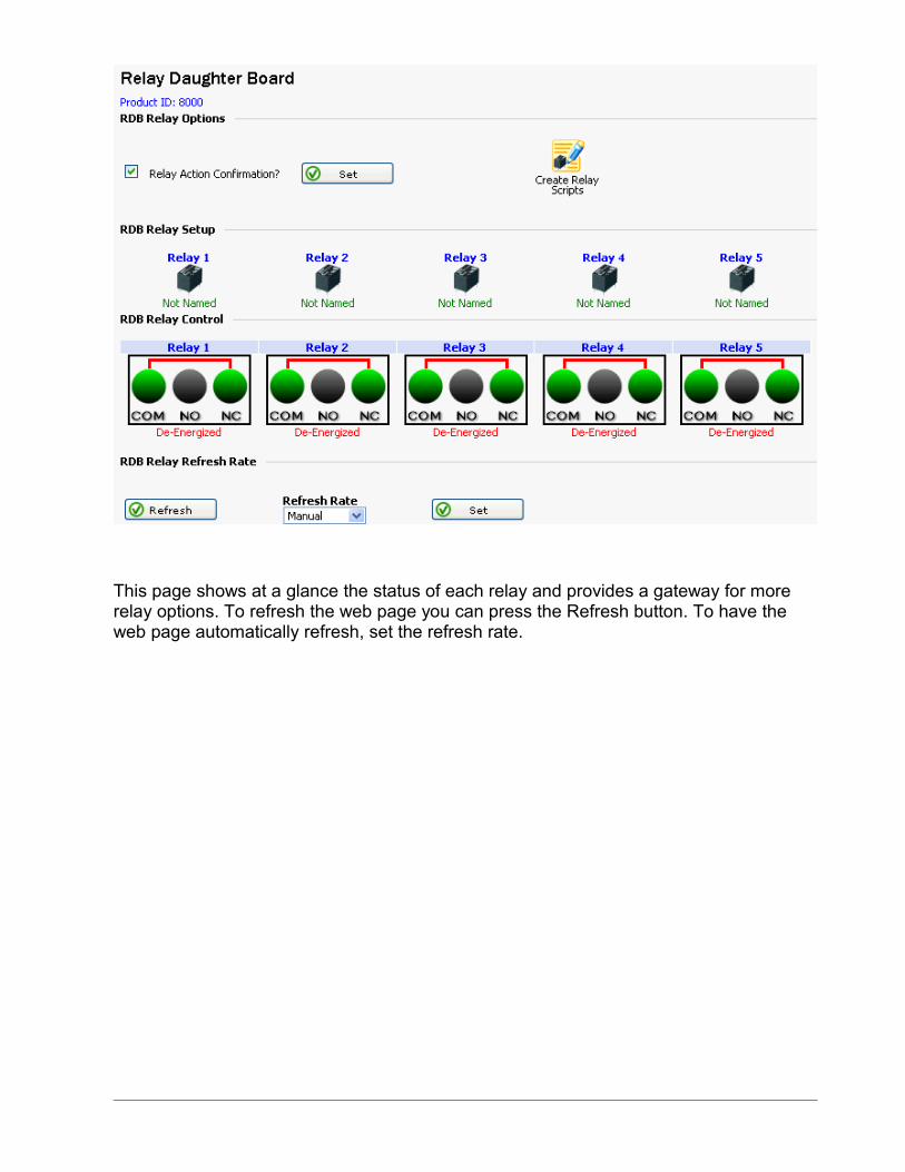
This page shows at a glance the status of each relay and provides a gateway for more relay options. To refresh the web page you can press the Refresh button. To have the web page automatically refresh, set the refresh rate.
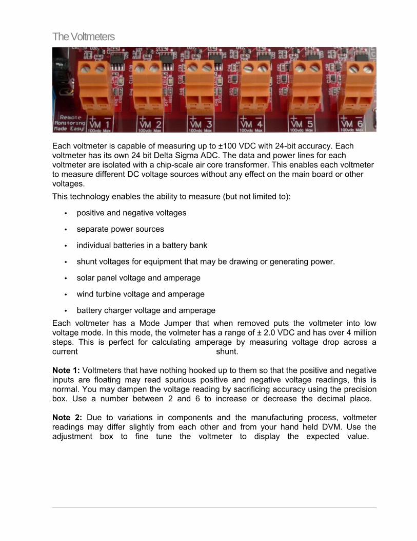
The Voltmeters
Each voltmeter is capable of measuring up to ±100 VDC with 24-bit accuracy. Each voltmeter has its own 24 bit Delta Sigma ADC. The data and power lines for each voltmeter are isolated with a chip-scale air core transformer. This enables each voltmeter to measure different DC voltage sources without any effect on the main board or other voltages.
This technology enables the ability to measure (but not limited to):
• positive and negative voltages
• separate power sources
• individual batteries in a battery bank
• shunt voltages for equipment that may be drawing or generating power.
• solar panel voltage and amperage
• wind turbine voltage and amperage
• battery charger voltage and amperage
Each voltmeter has a Mode Jumper that when removed puts the voltmeter into low voltage mode. In this mode, the volmeter has a range of ± 2.0 VDC and has over 4 million steps. This is perfect for calculating amperage by measuring voltage drop across a current shunt.
Note 1: Voltmeters that have nothing hooked up to them so that the positive and negative inputs are floating may read spurious positive and negative voltage readings, this is normal. You may dampen the voltage reading by sacrificing accuracy using the precision box. Use a number between 2 and 6 to increase or decrease the decimal place.
Note 2: Due to variations in components and the manufacturing process, voltmeter readings may differ slightly from each other and from your hand held DVM. Use the adjustment box to fine tune the voltmeter to display the expected value.
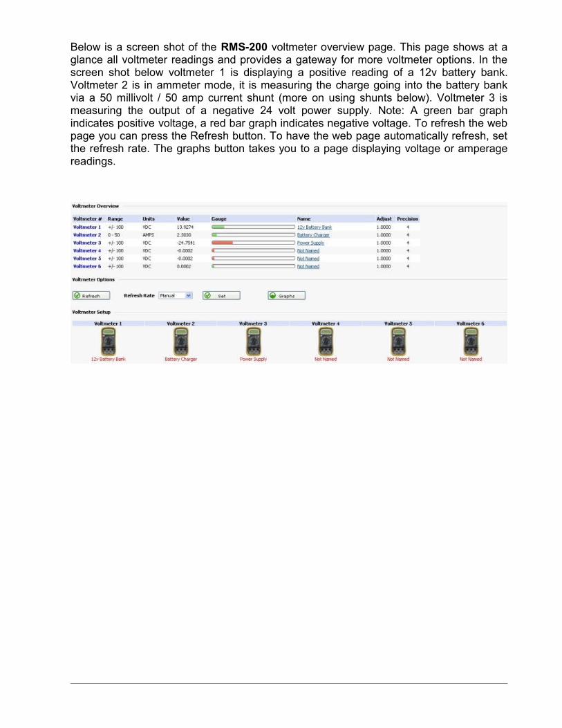
Below is a screen shot of the RMS-200 voltmeter overview page. This page shows at a glance all voltmeter readings and provides a gateway for more voltmeter options. In the screen shot below voltmeter 1 is displaying a positive reading of a 12v battery bank. Voltmeter 2 is in ammeter mode, it is measuring the charge going into the battery bank via a 50 millivolt / 50 amp current shunt (more on using shunts below). Voltmeter 3 is measuring the output of a negative 24 volt power supply. Note: A green bar graph indicates positive voltage, a red bar graph indicates negative voltage. To refresh the web page you can press the Refresh button. To have the web page automatically refresh, set the refresh rate. The graphs button takes you to a page displaying voltage or amperage readings.
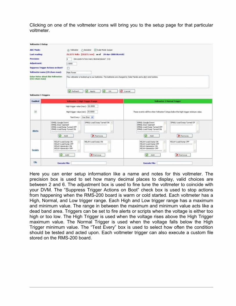
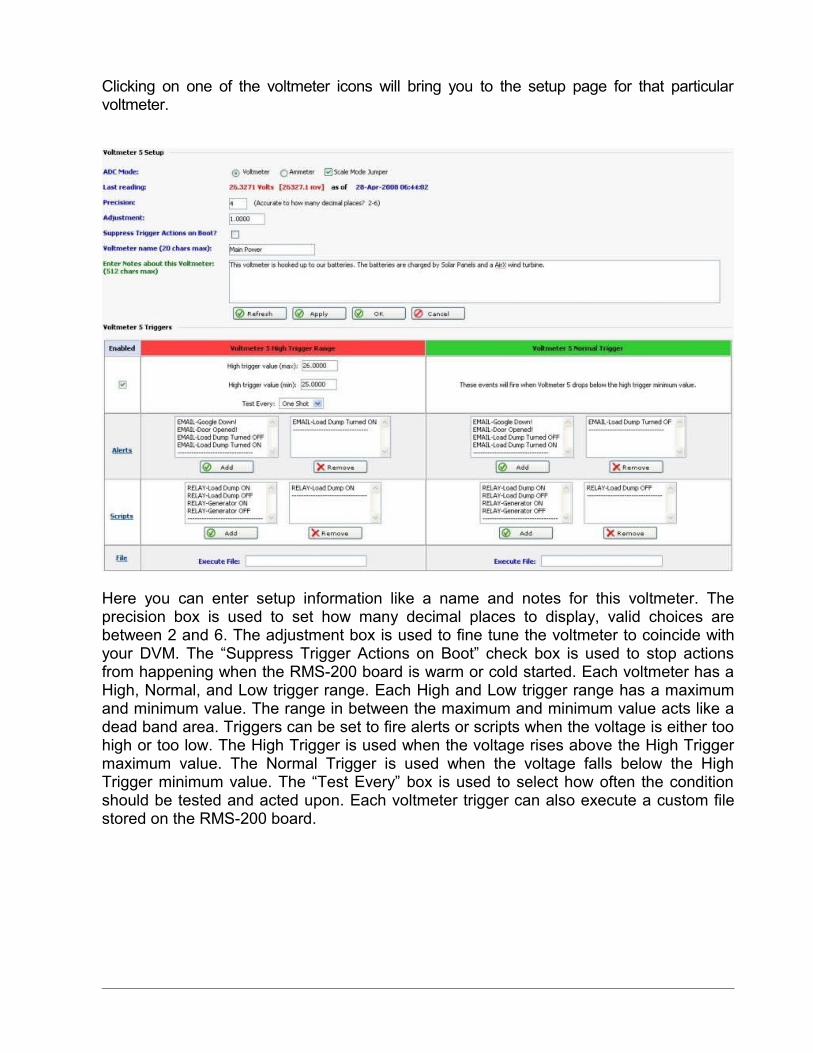
Clicking on one of the voltmeter icons will bring you to the setup page for that particular voltmeter.
Here you can enter setup information like a name and notes for this voltmeter. The precision box is used to set how many decimal places to display, valid choices are between 2 and 6. The adjustment box is used to fine tune the voltmeter to coincide with your DVM. The “Suppress Trigger Actions on Boot” check box is used to stop actions from happening when the RMS-200 board is warm or cold started. Each voltmeter has a High, Normal, and Low trigger range. Each High and Low trigger range has a maximum and minimum value. The range in between the maximum and minimum value acts like a dead band area. Triggers can be set to fire alerts or scripts when the voltage is either too high or too low. The High Trigger is used when the voltage rises above the High Trigger maximum value. The Normal Trigger is used when the voltage falls below the High Trigger minimum value. The “Test Every” box is used to select how often the condition should be tested and acted upon. Each voltmeter trigger can also execute a custom file stored on the RMS-200 board.
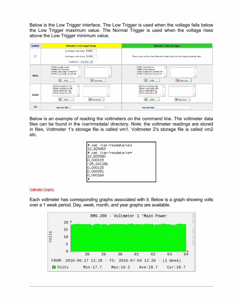
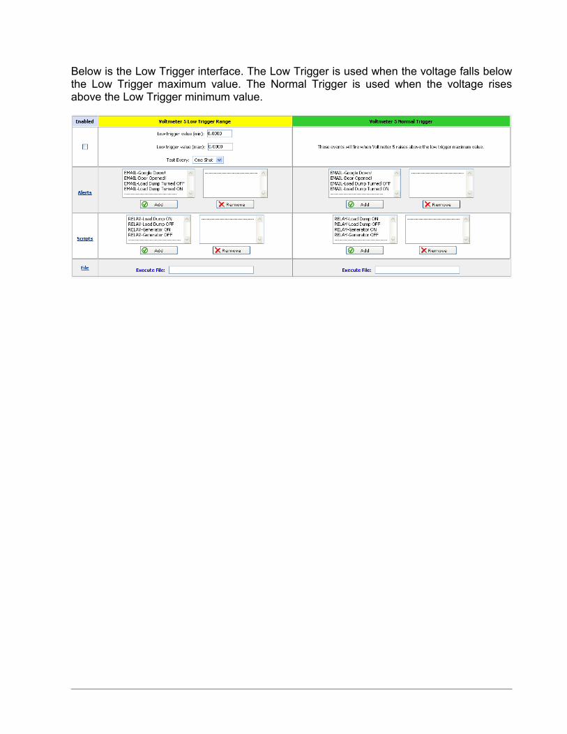
Below is the Low Trigger interface. The Low Trigger is used when the voltage falls below the Low Trigger maximum value. The Normal Trigger is used when the voltage rises above the Low Trigger minimum value.
Below is an example of reading the voltmeters on the command line. The voltmeter data files can be found in the /var/rmsdata/ directory. Note: the voltmeter readings are stored in files. Voltmeter 1's storage file is called vm1. Voltmeter 2's storage file is called vm2 etc.
Voltmeter Graphs
Each voltmeter has corresponding graphs associated with it. Below is a graph showing volts over a 1 week period. Day, week, month, and year graphs are available.
How to measure amperage by using a shunt
If you are managing a remote battery powered site, knowing your battery voltage is vital. It is also a key thing to know how much charging you are putting back into your batteries, and how much power is being consumed by your equipment. It is also a key thing to know how much charging you are putting back into your batteries. Using a common shunt, it is possible to obtain a millivolt reading that relates to an amperage reading. The voltmeters on the RMS-200 board are perfect for this as they are very sensitive and can easily read millivolt readings. For greater accuracy, put the RMS-200 voltmeters in to low voltage mode by removing the mode jumper for a particular voltmeter. Removing the mode jumper decreases the voltage range to +/- 2.0 volts and increases the granularity for increased accuracy when measuring millivolt values.
A word on shunts.
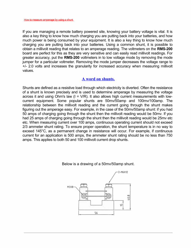
Shunts are defined as a resistive load through which electricity is diverted. Often the resistance of a shunt is known precisely and is used to determine amperage by measuring the voltage across it and using Ohm's law (I = V/R). It also allows high current measurements with low-current equipment. Some popular shunts are 50mv/50amp and 100mv/100amp. The relationship between the millivolt reading and the current going through the shunt makes figuring out the amperage easy. For example, in the case of the 50mv/50amp shunt: if you had 50 amps of charging going through the shunt then the millivolt reading would be 50mv. If you had 25 amps of charging going through the shunt then the millivolt reading would be 25mv etc etc. When measuring current over 100 amps, continuous operating current should not exceed 2/3 ammeter shunt rating. To ensure proper operation, the shunt temperature is in no way to exceed 145°C, as a permanent change in resistance will occur. For example, if continuous current for an application is 500 amps, the ammeter shunt rating should be no less than 750 amps. This applies to both 50 and 100 millivolt current drop shunts.
Below is a drawing of a 50mv/50amp shunt.
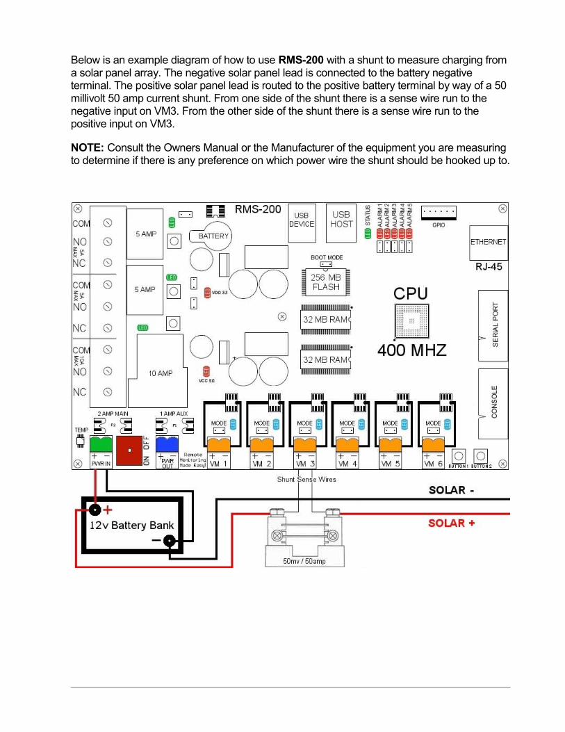
Below is an example diagram of how to use RMS-200 with a shunt to measure charging from a solar panel array. The negative solar panel lead is connected to the battery negative terminal. The positive solar panel lead is routed to the positive battery terminal by way of a 50 millivolt 50 amp current shunt. From one side of the shunt there is a sense wire run to the negative input on VM3. From the other side of the shunt there is a sense wire run to the positive input on VM3.
NOTE: Consult the Owners Manual or the Manufacturer of the equipment you are measuring to determine if there is any preference on which power wire the shunt should be hooked up to.
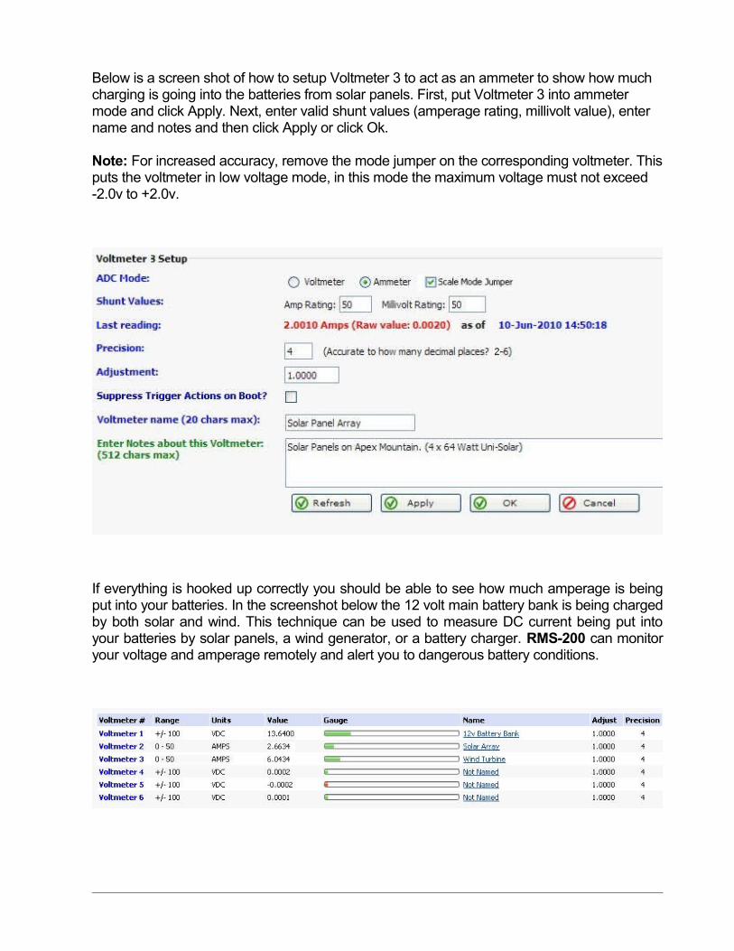
Below is a screen shot of how to setup Voltmeter 3 to act as an ammeter to show how much charging is going into the batteries from solar panels. First, put Voltmeter 3 into ammeter mode and click Apply. Next, enter valid shunt values (amperage rating, millivolt value), enter name and notes and then click Apply or click Ok.
Note: For increased accuracy, remove the mode jumper on the corresponding voltmeter. This puts the voltmeter in low voltage mode, in this mode the maximum voltage must not exceed -2.0v to +2.0v.
If everything is hooked up correctly you should be able to see how much amperage is being put into your batteries. In the screenshot below the 12 volt main battery bank is being charged by both solar and wind. This technique can be used to measure DC current being put into your batteries by solar panels, a wind generator, or a battery charger. RMS-200 can monitor your voltage and amperage remotely and alert you to dangerous battery conditions.
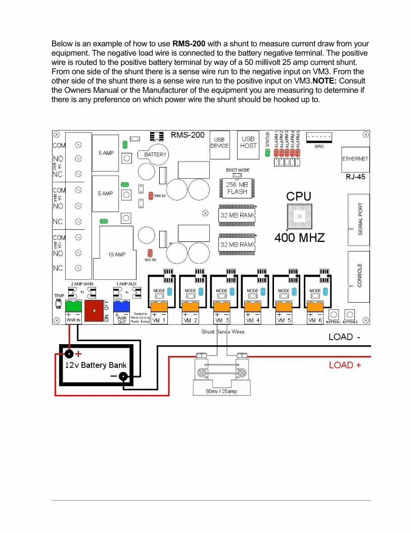
Below is an example of how to use RMS-200 with a shunt to measure current draw from your equipment. The negative load wire is connected to the battery negative terminal. The positive wire is routed to the positive battery terminal by way of a 50 millivolt 25 amp current shunt. From one side of the shunt there is a sense wire run to the negative input on VM3. From the other side of the shunt there is a sense wire run to the positive input on VM3.NOTE: Consult the Owners Manual or the Manufacturer of the equipment you are measuring to determine if there is any preference on which power wire the shunt should be hooked up to.
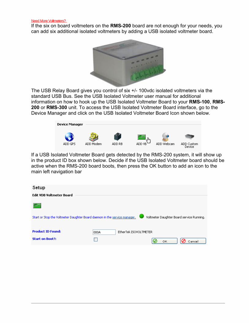
Need More Voltmeters?
If the six on board voltmeters on the RMS-200 board are not enough for your needs, you can add six additional isolated voltmeters by adding a USB isolated voltmeter board.
The USB Relay Board gives you control of six +/- 100vdc isolated voltmeters via the standard USB Bus. See the USB Isolated Voltmeter user manual for additional information on how to hook up the USB Isolated Voltmeter Board to your RMS-100, RMS-200 or RMS-300 unit. To access the USB Isolated Voltmeter Board interface, go to the Device Manager and click on the USB Isolated Voltmeter Board Icon shown below.
If a USB Isolated Voltmeter Board gets detected by the RMS-200 system, it will show up in the product ID box shown below. Decide if the USB Isolated Voltmeter board should be active when the RMS-200 board boots, then press the OK button to add an icon to the main left navigation bar

Clicking on the VDB icon in the left navigation bar takes you to the main setup page of the USB Isolated Voltmeter board. Below is a screen shot of the familiar voltmeter setup page.
This page shows at a glance all voltmeter readings and provides a gateway for more voltmeter options. In the screen shot above voltmeter 6 is displaying a positive reading of a 24v battery bank. Note: A green bar graph indicates positive voltage, a red bar graph indicates negative voltage. To refresh the web page you can press the Refresh button. To have the web page automatically refresh, set the refresh rate.
Clicking on one of the voltmeter icons will bring you to the setup page for that particular voltmeter.
Here you can enter setup information like a name and notes for this voltmeter. The precision box is used to set how many decimal places to display, valid choices are between 2 and 6. The adjustment box is used to fine tune the voltmeter to coincide with your DVM. The “Suppress Trigger Actions on Boot” check box is used to stop actions from happening when the RMS-200 board is warm or cold started. Each voltmeter has a High, Normal, and Low trigger range. Each High and Low trigger range has a maximum and minimum value. The range in between the maximum and minimum value acts like a dead band area. Triggers can be set to fire alerts or scripts when the voltage is either too high or too low. The High Trigger is used when the voltage rises above the High Trigger maximum value. The Normal Trigger is used when the voltage falls below the High Trigger minimum value. The “Test Every” box is used to select how often the condition should be tested and acted upon. Each voltmeter trigger can also execute a custom file stored on the RMS-200 board.
Below is the Low Trigger interface. The Low Trigger is used when the voltage falls below the Low Trigger maximum value. The Normal Trigger is used when the voltage rises above the Low Trigger minimum value.
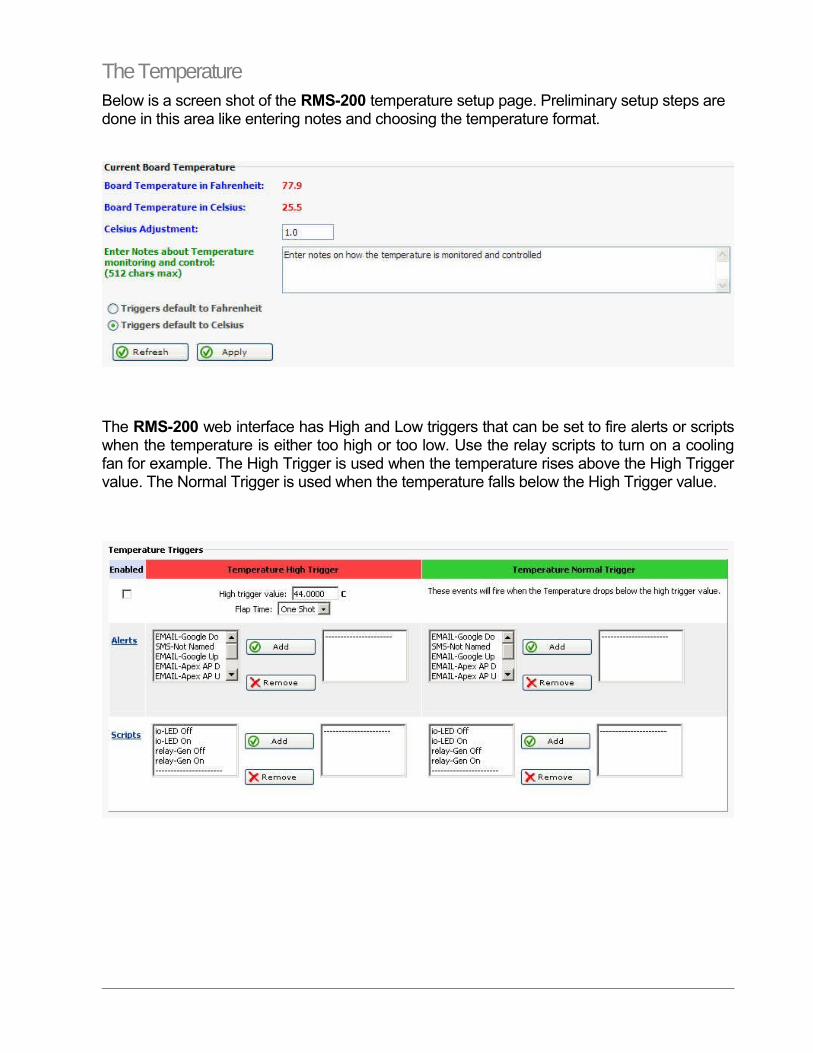
The TemperatureBelow is a screen shot of the RMS-200 temperature setup page. Preliminary setup steps are done in this area like entering notes and choosing the temperature format.
The RMS-200 web interface has High and Low triggers that can be set to fire alerts or scripts when the temperature is either too high or too low. Use the relay scripts to turn on a cooling fan for example. The High Trigger is used when the temperature rises above the High Trigger value. The Normal Trigger is used when the temperature falls below the High Trigger value.
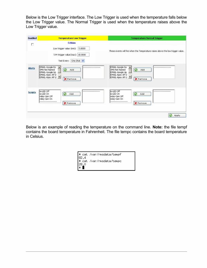
Below is the Low Trigger interface. The Low Trigger is used when the temperature falls below the Low Trigger value. The Normal Trigger is used when the temperature raises above the Low Trigger value.
Below is an example of reading the temperature on the command line. Note: the file tempf contains the board temperature in Fahrenheit. The file tempc contains the board temperature in Celsius.
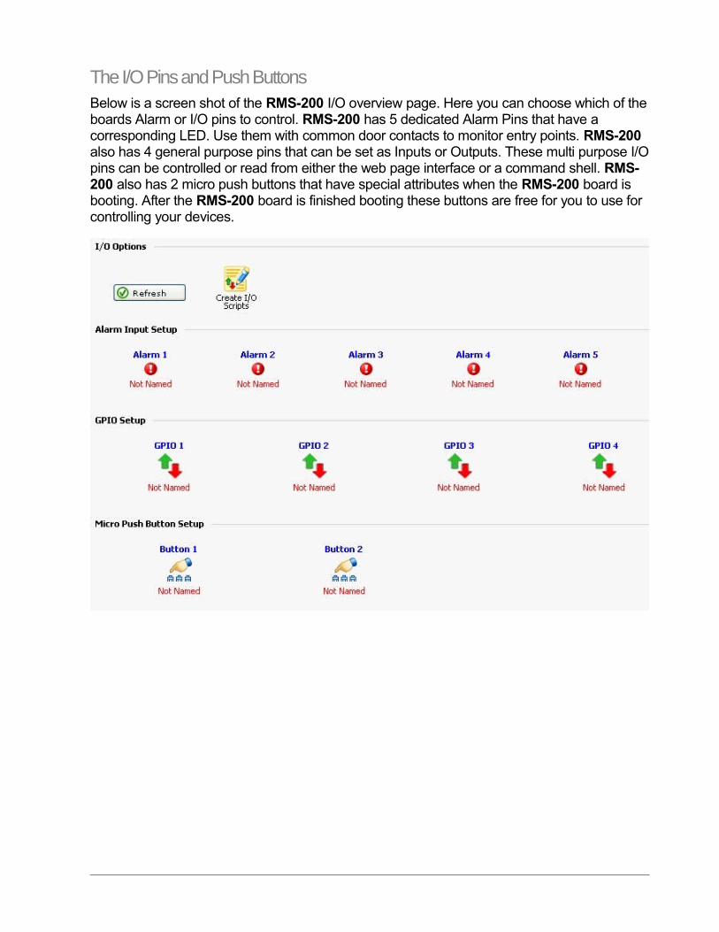
The I/O Pins and Push ButtonsBelow is a screen shot of the RMS-200 I/O overview page. Here you can choose which of the boards Alarm or I/O pins to control. RMS-200 has 5 dedicated Alarm Pins that have a corresponding LED. Use them with common door contacts to monitor entry points. RMS-200 also has 4 general purpose pins that can be set as Inputs or Outputs. These multi purpose I/O pins can be controlled or read from either the web page interface or a command shell. RMS-200 also has 2 micro push buttons that have special attributes when the RMS-200 board is booting. After the RMS-200 board is finished booting these buttons are free for you to use for controlling your devices.
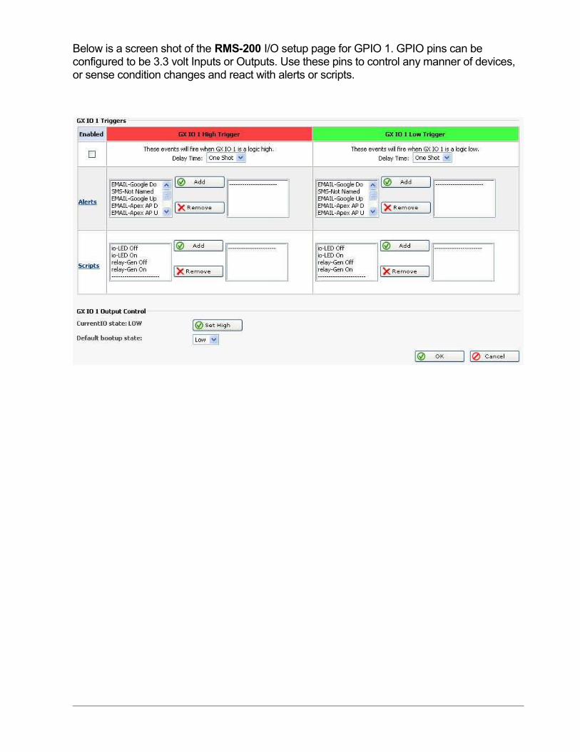
Below is a screen shot of the RMS-200 I/O setup page for GPIO 1. GPIO pins can be configured to be 3.3 volt Inputs or Outputs. Use these pins to control any manner of devices, or sense condition changes and react with alerts or scripts.
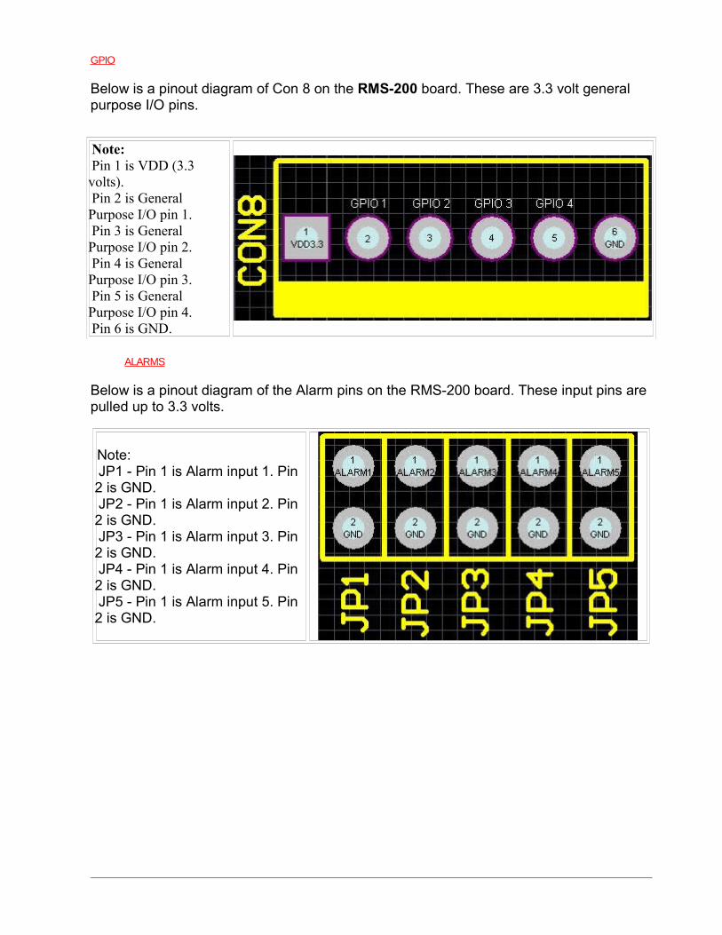
GPIO
Below is a pinout diagram of Con 8 on the RMS-200 board. These are 3.3 volt general purpose I/O pins.
Note: Pin 1 is VDD (3.3 volts). Pin 2 is General Purpose I/O pin 1. Pin 3 is General Purpose I/O pin 2. Pin 4 is General Purpose I/O pin 3. Pin 5 is General Purpose I/O pin 4. Pin 6 is GND.
ALARMS
Below is a pinout diagram of the Alarm pins on the RMS-200 board. These input pins are pulled up to 3.3 volts.
Note: JP1 - Pin 1 is Alarm input 1. Pin 2 is GND. JP2 - Pin 1 is Alarm input 2. Pin 2 is GND. JP3 - Pin 1 is Alarm input 3. Pin 2 is GND. JP4 - Pin 1 is Alarm input 4. Pin 2 is GND. JP5 - Pin 1 is Alarm input 5. Pin 2 is GND.
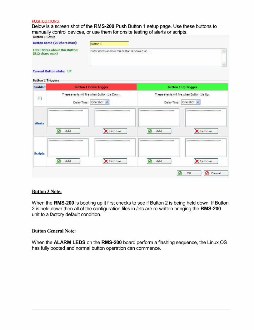
PUSH BUTTONS
Below is a screen shot of the RMS-200 Push Button 1 setup page. Use these buttons to manually control devices, or use them for onsite testing of alerts or scripts.
Button 3 Note:
When the RMS-200 is booting up it first checks to see if Button 2 is being held down. If Button 2 is held down then all of the configuration files in /etc are re-written bringing the RMS-200 unit to a factory default condition.
Button General Note:
When the ALARM LEDS on the RMS-200 board perform a flashing sequence, the Linux OS has fully booted and normal button operation can commence.
USB SupportCAMERAS
RMS-200 uses the UVC driver that supports a wide variety of USB web cameras. These inexpensive cameras come in handy to passively monitor things like door ways, fuel gauges, LCD displays, etc.
USB to SERIAL
RMS-200 has built in USB to Serial converter drivers. Support for “generic type” and USB to Serial converters that use the “Prolific” chipset.
USB WIRELESS
RMS-200 uses the RayLink wireless device driver. Some USB wireless devices such as the Dlink USB stick have been tested giving RMS-200 an alternative path to the internet.
GENERAL USB SUPPORT
RMS-200 supports a wide variety of USB devices. Check with us to find out if your USB device can be made compatible with RMS-200.
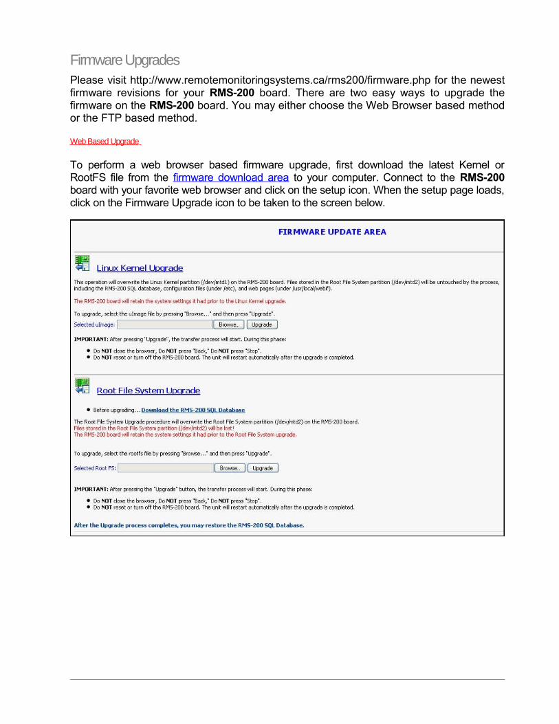
Firmware UpgradesPlease visit http://www.remotemonitoringsystems.ca/rms200/firmware.php for the newest firmware revisions for your RMS-200 board. There are two easy ways to upgrade the firmware on the RMS-200 board. You may either choose the Web Browser based method or the FTP based method.
Web Based Upgrade
To perform a web browser based firmware upgrade, first download the latest Kernel or RootFS file from the firmware download area to your computer. Connect to the RMS-200 board with your favorite web browser and click on the setup icon. When the setup page loads, click on the Firmware Upgrade icon to be taken to the screen below.
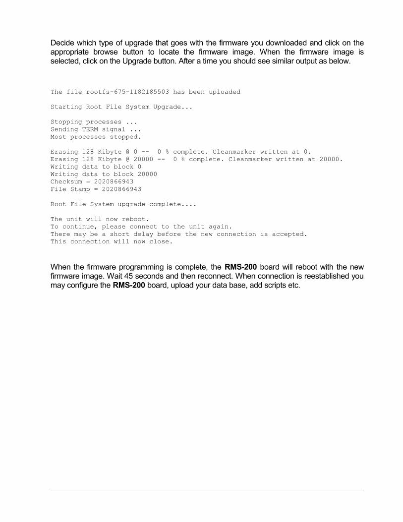
Decide which type of upgrade that goes with the firmware you downloaded and click on the appropriate browse button to locate the firmware image. When the firmware image is selected, click on the Upgrade button. After a time you should see similar output as below.
The file rootfs-675-1182185503 has been uploaded
Starting Root File System Upgrade...
Stopping processes ...Sending TERM signal ...Most processes stopped.
Erasing 128 Kibyte @ 0 -- 0 % complete. Cleanmarker written at 0.Erasing 128 Kibyte @ 20000 -- 0 % complete. Cleanmarker written at 20000.Writing data to block 0Writing data to block 20000Checksum = 2020866943File Stamp = 2020866943
Root File System upgrade complete....
The unit will now reboot.To continue, please connect to the unit again.There may be a short delay before the new connection is accepted.This connection will now close.
When the firmware programming is complete, the RMS-200 board will reboot with the new firmware image. Wait 45 seconds and then reconnect. When connection is reestablished you may configure the RMS-200 board, upload your data base, add scripts etc.
FTP Based Upgrade
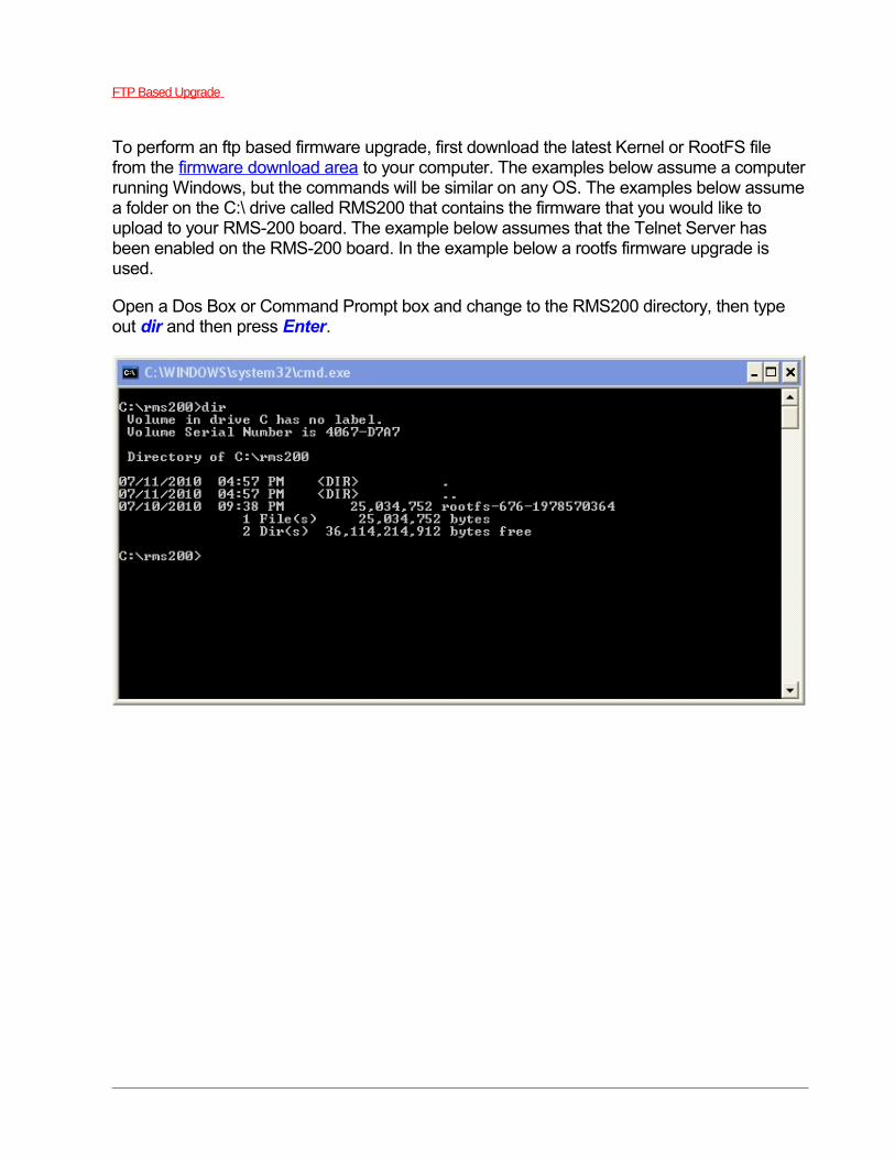
To perform an ftp based firmware upgrade, first download the latest Kernel or RootFS file from the firmware download area to your computer. The examples below assume a computer running Windows, but the commands will be similar on any OS. The examples below assume a folder on the C:\ drive called RMS200 that contains the firmware that you would like to upload to your RMS-200 board. The example below assumes that the Telnet Server has been enabled on the RMS-200 board. In the example below a rootfs firmware upgrade is used.
Open a Dos Box or Command Prompt box and change to the RMS200 directory, then type out dir and then press Enter.
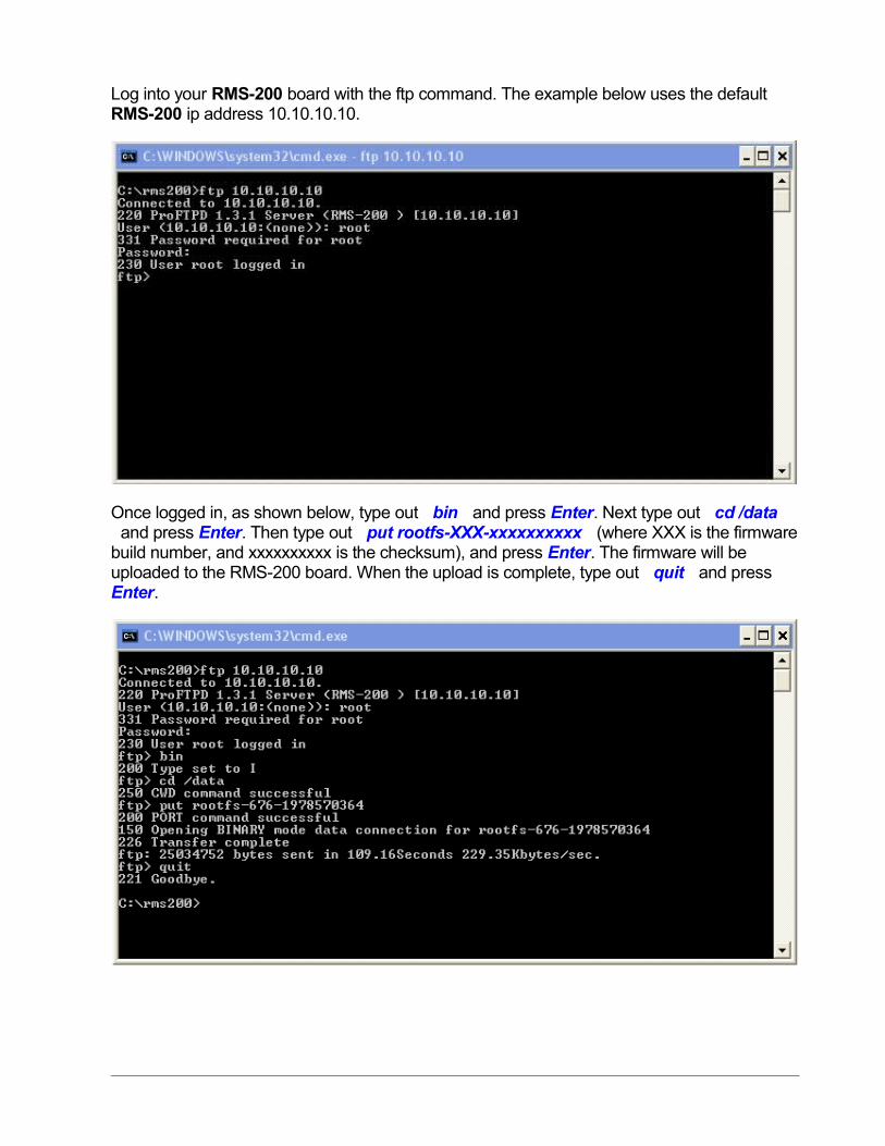
Log into your RMS-200 board with the ftp command. The example below uses the default RMS-200 ip address 10.10.10.10.
Once logged in, as shown below, type out bin and press Enter. Next type out cd /data and press Enter. Then type out put rootfs-XXX-xxxxxxxxxx (where XXX is the firmware build number, and xxxxxxxxxx is the checksum), and press Enter. The firmware will be uploaded to the RMS-200 board. When the upload is complete, type out quit and press Enter.
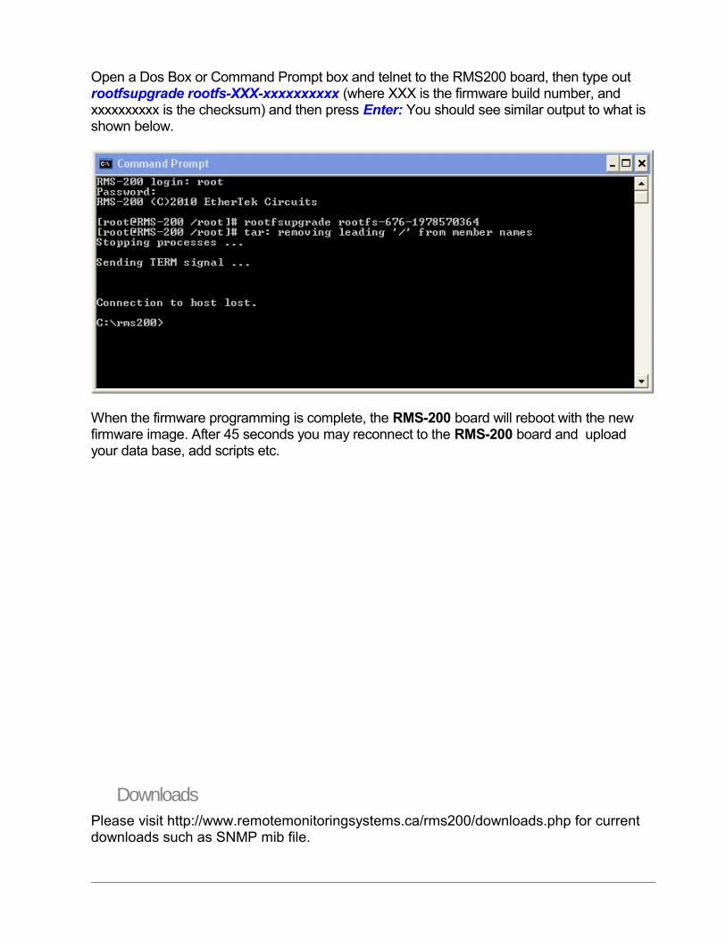
Open a Dos Box or Command Prompt box and telnet to the RMS200 board, then type out rootfsupgrade rootfs-XXX-xxxxxxxxxx (where XXX is the firmware build number, and xxxxxxxxxx is the checksum) and then press Enter: You should see similar output to what is shown below.
When the firmware programming is complete, the RMS-200 board will reboot with the new firmware image. After 45 seconds you may reconnect to the RMS-200 board and upload your data base, add scripts etc.
DownloadsPlease visit http://www.remotemonitoringsystems.ca/rms200/downloads.php for current downloads such as SNMP mib file.
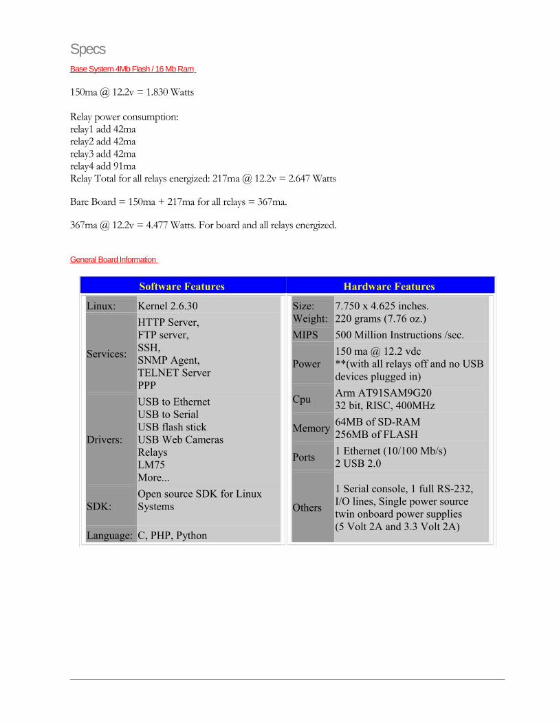
SpecsBase System 4Mb Flash / 16 Mb Ram
150ma @ 12.2v = 1.830 Watts
Relay power consumption:relay1 add 42marelay2 add 42marelay3 add 42marelay4 add 91maRelay Total for all relays energized: 217ma @ 12.2v = 2.647 Watts
Bare Board = 150ma + 217ma for all relays = 367ma.
367ma @ 12.2v = 4.477 Watts. For board and all relays energized.
General Board Information
Software Features Hardware Features
Linux: Kernel 2.6.30
Services:
HTTP Server,FTP server, SSH,SNMP Agent,TELNET ServerPPP
Drivers:
USB to EthernetUSB to SerialUSB flash stickUSB Web CamerasRelaysLM75More...
SDK:Open source SDK for Linux Systems
Language: C, PHP, Python
Size:Weight:
7.750 x 4.625 inches.220 grams (7.76 oz.)
MIPS 500 Million Instructions /sec.
Power150 ma @ 12.2 vdc**(with all relays off and no USB devices plugged in)
CpuArm AT91SAM9G2032 bit, RISC, 400MHz
Memory64MB of SD-RAM256MB of FLASH
Ports1 Ethernet (10/100 Mb/s)2 USB 2.0
Others
1 Serial console, 1 full RS-232, I/O lines, Single power source twin onboard power supplies(5 Volt 2A and 3.3 Volt 2A)
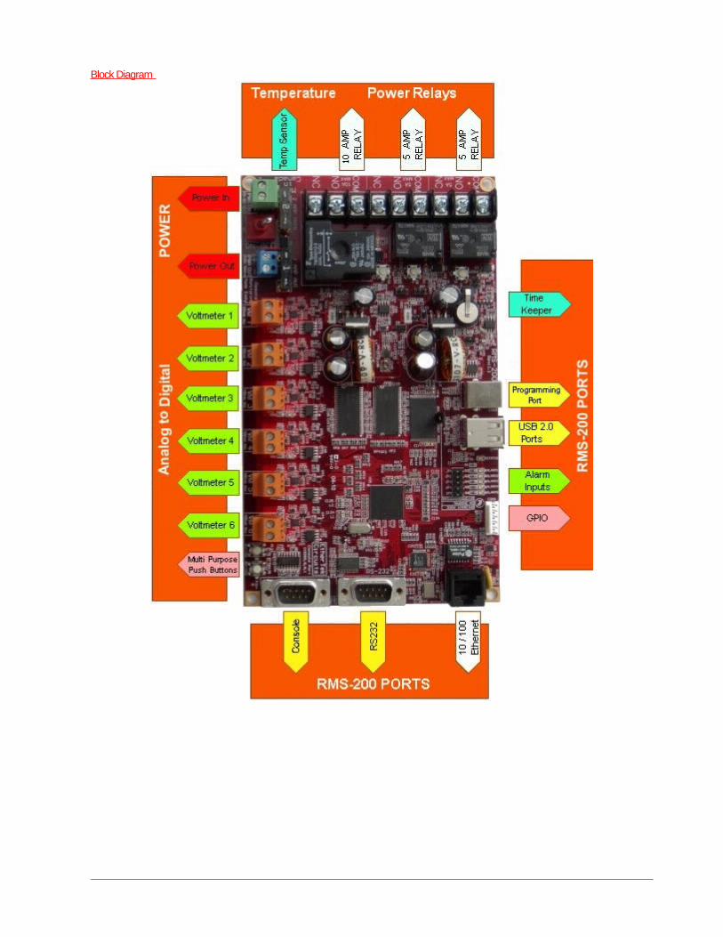
Block Diagram
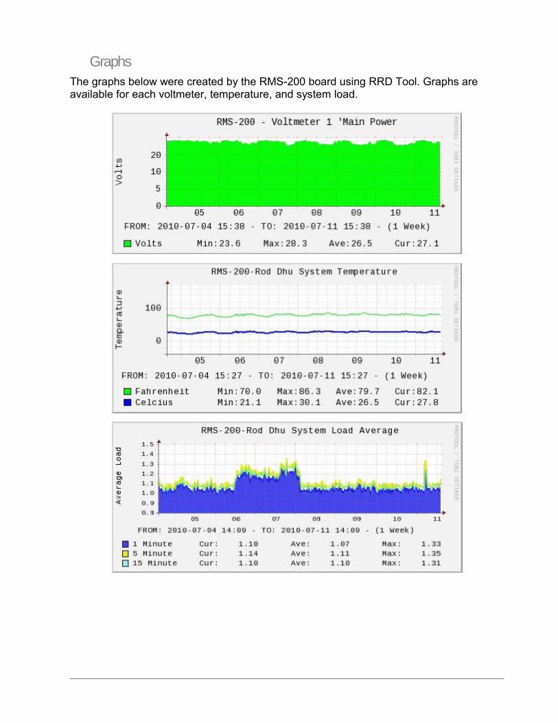
GraphsThe graphs below were created by the RMS-200 board using RRD Tool. Graphs are available for each voltmeter, temperature, and system load.
WarrantyRMS-200 One (1) Year Limited Warranty
WARRANTY COVERAGE
EtherTek Circuits warranty obligations are limited to the terms set forth below:
EtherTek Circuits warrants their hardware products against defects in materials and workmanship for a period of ONE (1) YEAR from the date of original retail purchase. If a defect exists, at its option EtherTek Circuits will (1) repair the product at no charge, using new or refurbished replacement parts, (2) exchange the product with a product that is new or which has been manufactured from new or serviceable used parts and is at least functionally equivalent to the original product, or (3) refund the purchase price of the product. A replacement product/part assumes the remaining warranty of the original product or ninety (90) days from the date of replacement or repair, whichever provides longer coverage for you. When a product or part is exchanged, any replacement item becomes your property and the replaced item becomes EtherTek Circuits property. When a refund is given, your product becomes the property of EtherTek Circuits. Contact your RMS-200 retailer for warranty instructions.
EXCLUSIONS AND LIMITATIONS
Software distributed by EtherTek Circuits is not covered under this Limited Warranty. Recovery and reinstallation of application software and user data are not covered under this Limited Warranty. EtherTek Circuits and its Authorized Resellers are not liable for any damage to equipment, buildings and/or property by the use or misuse of our products. This warranty does not apply: (a) to damage caused by accident, abuse, misuse, misapplication; (b) to damage caused by service (including upgrades and expansions) performed by anyone who is not an EtherTek Circuits Authorized Service Provider; (c) to a product or a part that has been modified without the written permission of EtherTek Circuits.
The RMS-200 circuit boards are supplied as OEM-type equipment and not in retail form. It is imperative that the user/purchaser understands the correct installation, configuration and operation of this equipment. Operation and configuration information is available via the website and is updated regularly. We recommend reviewing the website materials before powering the boards. The manufacturer and distributor cannot be held responsible for improper installation and configuration of this equipment and/or any damage caused by its improper use.
Interfacing external components or equipment to the RMS-200 boards is not intended for the novice electronics hobbyist, medium to advanced knowledge of electronic circuit design is necessary. The manufacturer and distributor cannot be held responsible for improper interfacing of custom circuits or equipment that damage the RMS-200 circuit boards or other equipment or property.
THIS WARRANTY AND REMEDIES SET FORTH ABOVE ARE EXCLUSIVE AND IN LIEU OF ALL OTHER WARRANTIES, REMEDIES AND CONDITIONS, WHETHER ORAL OR WRITTEN, EXPRESS OR IMPLIED. EtherTek Circuits SPECIFICALLY DISCLAIMS ANY AND ALL IMPLIED WARRANTIES, INCLUDING, WITHOUT LIMITATION, WARRANTIES OF MERCHANTABILITY AND FITNESS FOR A PARTICULAR PURPOSE.

IF EtherTek Circuits CANNOT LAWFULLY DISCLAIM IMPLIED WARRANTIES UNDER THIS LIMITED WARRANTY, ALL SUCH WARRANTIES, INCLUDING WARRANTIES OF MERCHANTABILITY AND FITNESS FOR A PARTICULAR PURPOSE ARE LIMITED IN DURATION TO THE DURATION OF THIS WARRANTY.