Embed Size (px)
Citation preview
1 Simulate to Innovate
Geometric Nonlinear Analysis of Flexible Structures Using Radioss Software
Imtiaj khan Scientist
Aerial Delivery Research and Development Establishment,
(ADRDE), DRDO, Agra [email protected]
R. K. Sharma Scientist
Aerial Delivery Research and Development Establishment
(ADRDE), DRDO, Agra
Dr. S. C. Sati Director
Aerial Delivery Research and Development Establishment
(ADRDE), DRDO, Agra
Abstract
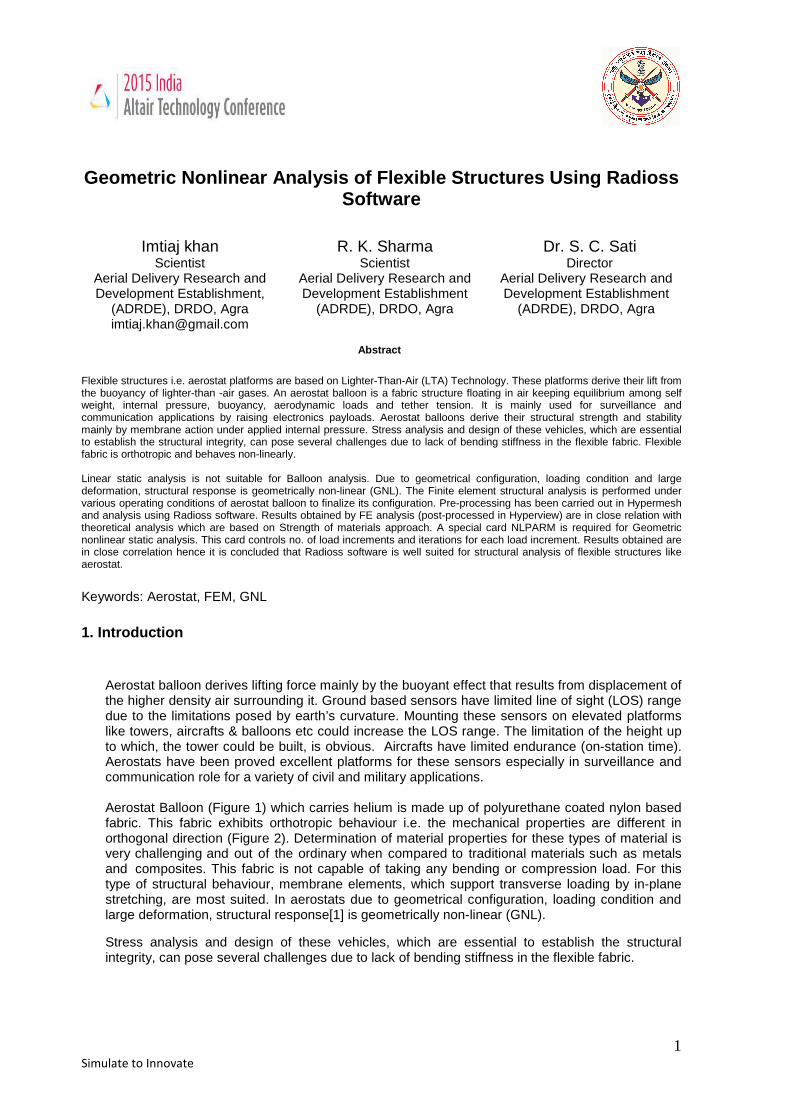
Flexible structures i.e. aerostat platforms are based on Lighter-Than-Air (LTA) Technology. These platforms derive their lift from the buoyancy of lighter-than -air gases. An aerostat balloon is a fabric structure floating in air keeping equilibrium among self weight, internal pressure, buoyancy, aerodynamic loads and tether tension. It is mainly used for surveillance and communication applications by raising electronics payloads. Aerostat balloons derive their structural strength and stability mainly by membrane action under applied internal pressure. Stress analysis and design of these vehicles, which are essential to establish the structural integrity, can pose several challenges due to lack of bending stiffness in the flexible fabric. Flexible fabric is orthotropic and behaves non-linearly. Linear static analysis is not suitable for Balloon analysis. Due to geometrical configuration, loading condition and large deformation, structural response is geometrically non-linear (GNL). The Finite element structural analysis is performed under various operating conditions of aerostat balloon to finalize its configuration. Pre-processing has been carried out in Hypermesh and analysis using Radioss software. Results obtained by FE analysis (post-processed in Hyperview) are in close relation with theoretical analysis which are based on Strength of materials approach. A special card NLPARM is required for Geometric nonlinear static analysis. This card controls no. of load increments and iterations for each load increment. Results obtained are in close correlation hence it is concluded that Radioss software is well suited for structural analysis of flexible structures like aerostat.
Keywords: Aerostat, FEM, GNL
1. Introduction
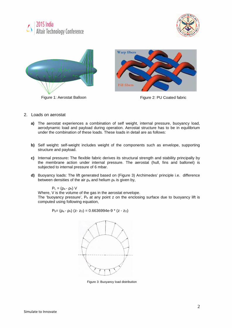
Aerostat balloon derives lifting force mainly by the buoyant effect that results from displacement of the higher density air surrounding it. Ground based sensors have limited line of sight (LOS) range due to the limitations posed by earth’s curvature. Mounting these sensors on elevated platforms like towers, aircrafts & balloons etc could increase the LOS range. The limitation of the height up to which, the tower could be built, is obvious. Aircrafts have limited endurance (on-station time). Aerostats have been proved excellent platforms for these sensors especially in surveillance and communication role for a variety of civil and military applications. Aerostat Balloon (Figure 1) which carries helium is made up of polyurethane coated nylon based fabric. This fabric exhibits orthotropic behaviour i.e. the mechanical properties are different in orthogonal direction (Figure 2). Determination of material properties for these types of material is very challenging and out of the ordinary when compared to traditional materials such as metals and composites. This fabric is not capable of taking any bending or compression load. For this type of structural behaviour, membrane elements, which support transverse loading by in-plane stretching, are most suited. In aerostats due to geometrical configuration, loading condition and large deformation, structural response[1] is geometrically non-linear (GNL). Stress analysis and design of these vehicles, which are essential to establish the structural integrity, can pose several challenges due to lack of bending stiffness in the flexible fabric.
2 Simulate to Innovate
Figure 1: Aerostat Balloon 2. Loads on aerostat
a) The aerostat experiences a combination of self weight, internal pressure, buoyancy load, aerodynamic load and payload during operation. Aerostat structure has to be in equilibrium under the combination of these loads. These loads in detail are as follows:
b) Self weight: self-weight includes weight of the components such as envelope, supporting
structure and payload.
c) Internal pressure: The flexible fabric derives its structural strength and stability principally by the membrane action under internal pressure. The aerostat (hull, fins and ballonet) is subjected to internal pressure of 6 mbar.
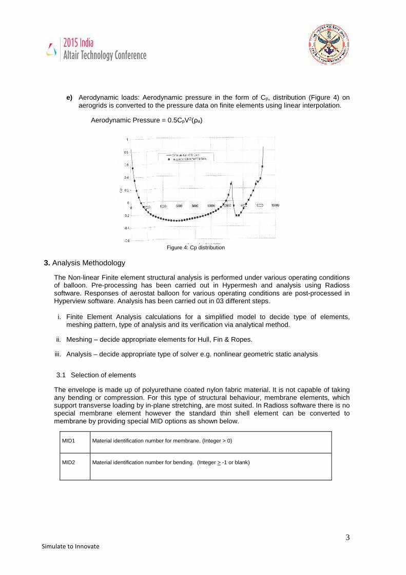
d) Buoyancy loads: The lift generated based on (Figure 3) Archimedes’ principle i.e. difference between densities of the air ρa and helium ρh is given by,
PL = (ρa - ρh) V Where, V is the volume of the gas in the aerostat envelope. The ‘buoyancy pressure’, Pb at any point z on the enclosing surface due to buoyancy lift is computed using following equation,
Pb= (ρa - ρh) (z- zO) = 0.6636994e-9 * (z - zO)
3. 4. 5. 6. 7. 8. 9.
Figure 3: Buoyancy load distribution
Figure 2: PU Coated fabric
3 Simulate to Innovate
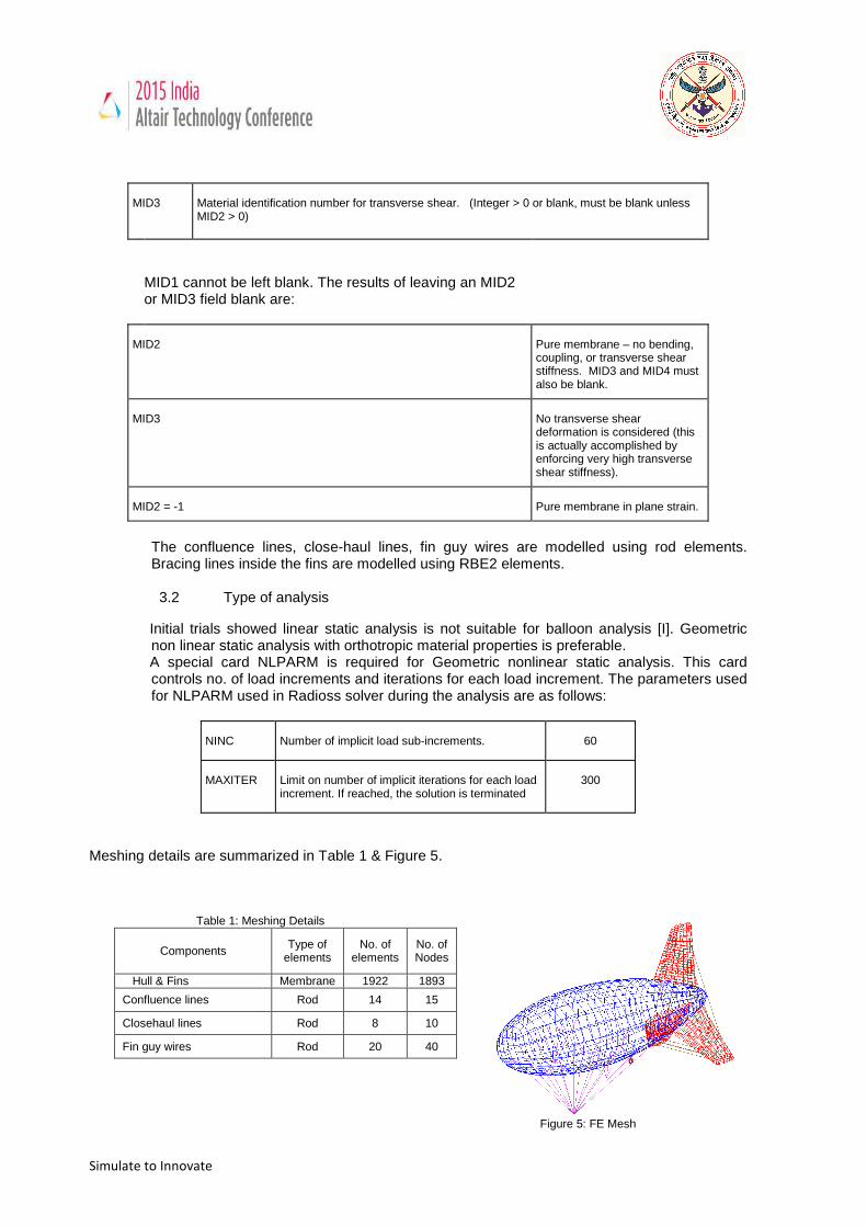
e) Aerodynamic loads: Aerodynamic pressure in the form of Cp, distribution (Figure 4) on
aerogrids is converted to the pressure data on finite elements using linear interpolation.
Aerodynamic Pressure = 0.5CpV2(ρa)
Figure 4: Cp distribution
3. Analysis Methodology
The Non-linear Finite element structural analysis is performed under various operating conditions of balloon. Pre-processing has been carried out in Hypermesh and analysis using Radioss software. Responses of aerostat balloon for various operating conditions are post-processed in Hyperview software. Analysis has been carried out in 03 different steps.
i. Finite Element Analysis calculations for a simplified model to decide type of elements,
meshing pattern, type of analysis and its verification via analytical method.
ii. Meshing – decide appropriate elements for Hull, Fin & Ropes.
iii. Analysis – decide appropriate type of solver e.g. nonlinear geometric static analysis
3.1 Selection of elements
The envelope is made up of polyurethane coated nylon fabric material. It is not capable of taking any bending or compression. For this type of structural behaviour, membrane elements, which support transverse loading by in-plane stretching, are most suited. In Radioss software there is no special membrane element however the standard thin shell element can be converted to membrane by providing special MID options as shown below.
MID1 Material identification number for membrane. (Integer > 0)
MID2 Material identification number for bending. (Integer > -1 or blank)
4 Simulate to Innovate
MID3 Material identification number for transverse shear. (Integer > 0 or blank, must be blank unless MID2 > 0)
MID1 cannot be left blank. The results of leaving an MID2 or MID3 field blank are:
MID2 Pure membrane – no bending, coupling, or transverse shear stiffness. MID3 and MID4 must also be blank.
MID3 No transverse shear deformation is considered (this is actually accomplished by enforcing very high transverse shear stiffness).
MID2 = -1 Pure membrane in plane strain.
The confluence lines, close-haul lines, fin guy wires are modelled using rod elements. Bracing lines inside the fins are modelled using RBE2 elements.
3.2 Type of analysis
Initial trials showed linear static analysis is not suitable for balloon analysis [I]. Geometric non linear static analysis with orthotropic material properties is preferable.
A special card NLPARM is required for Geometric nonlinear static analysis. This card controls no. of load increments and iterations for each load increment. The parameters used for NLPARM used in Radioss solver during the analysis are as follows:
NINC Number of implicit load sub-increments. 60
MAXITER Limit on number of implicit iterations for each load increment. If reached, the solution is terminated
300
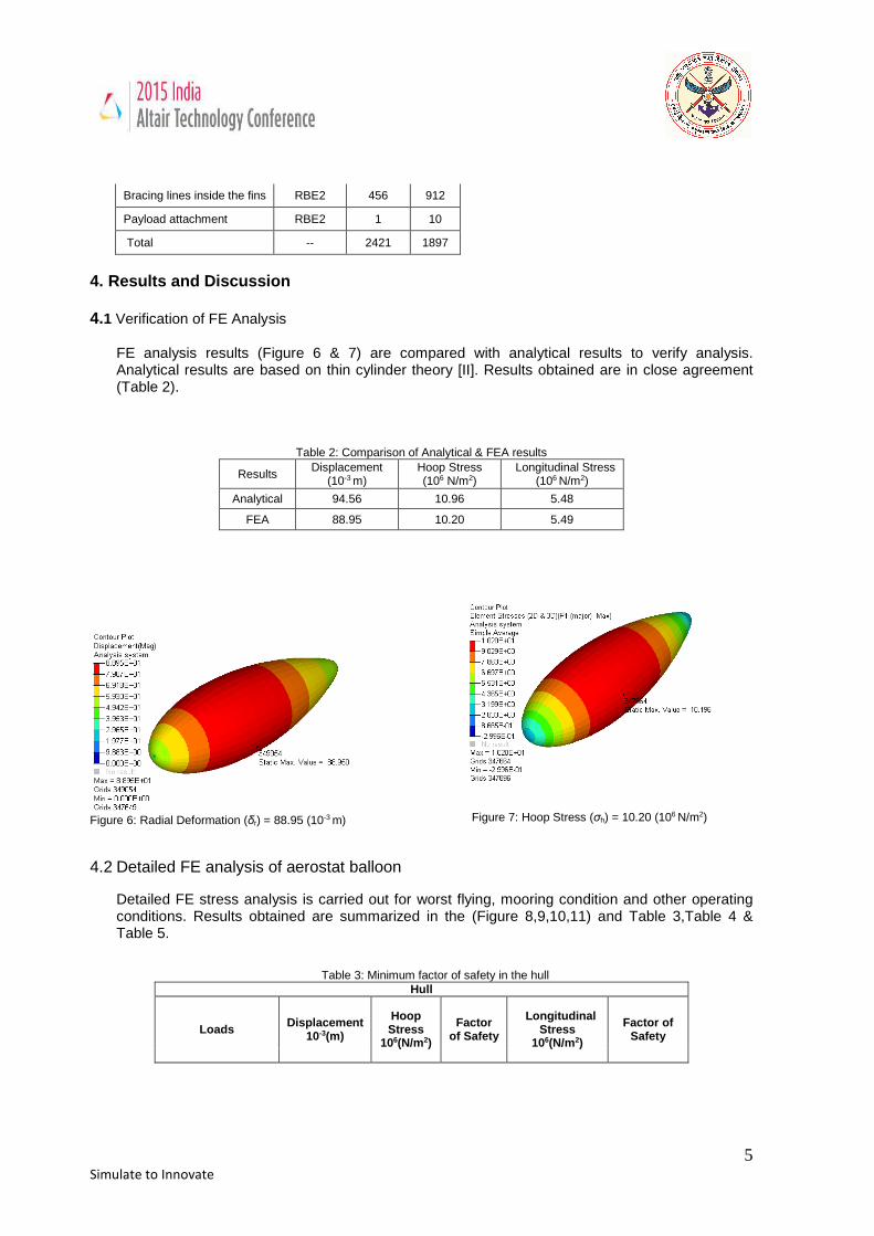
Meshing details are summarized in Table 1 & Figure 5.
Table 1: Meshing Details
Components Type of elements
No. of elements
No. of Nodes
Hull & Fins Membrane 1922 1893
Confluence lines Rod 14 15
Closehaul lines Rod 8 10
Fin guy wires Rod 20 40
Figure 5: FE Mesh
5 Simulate to Innovate
Bracing lines inside the fins RBE2 456 912
Payload attachment RBE2 1 10
Total -- 2421 1897
4. Results and Discussion 4.1 Verification of FE Analysis
FE analysis results (Figure 6 & 7) are compared with analytical results to verify analysis. Analytical results are based on thin cylinder theory [II]. Results obtained are in close agreement (Table 2).
Table 2: Comparison of Analytical & FEA results
Results Displacement
(10-3 m) Hoop Stress (106 N/m2)
Longitudinal Stress (106 N/m2)
Analytical 94.56 10.96 5.48
FEA 88.95 10.20 5.49
Figure 6: Radial Deformation (δr) = 88.95 (10-3
m) 4.2 Detailed FE analysis of aerostat balloon
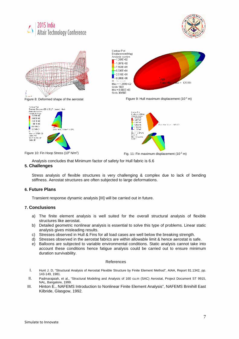
Detailed FE stress analysis is carried out for worst flying, mooring condition and other operating conditions. Results obtained are summarized in the (Figure 8,9,10,11) and Table 3,Table 4 & Table 5.
Table 3: Minimum factor of safety in the hull Hull
Loads Displacement 10-3(m)
Hoop Stress
106(N/m2)
Factor of Safety
Longitudinal Stress
106(N/m2)
Factor of Safety
Figure 7: Hoop Stress (σh) = 10.20 (106 N/m2)
6 Simulate to Innovate
Internal pressure 125.88 10.36 13.4 5.55 25.0
Operating condition 1255.72 9.96 13.9 6.28 22.1
Worst flying 1422.42 9.94 14.0 6.59 21.1
Worst mooring 1678.55 20.91 6.6 9.04 15.4
Table 4: Minimum factor of safety in the fin Fin
Loads Displacement 10-3(m)
Hoop Stress
106(N/m2)
Factor of Safety
Longitudinal Stress
106(N/m2)
Factor of
Safety
Internal pressure 65.07 1.56 64.1 1.23 81.3
Operating condition 1255.72 3.60 27.8 1.61 62.1
Worst flying 1419.40 5.73 17.5 1.91 52.4 Worst mooring 1768.43 4.37 22.9 2.01 49.8
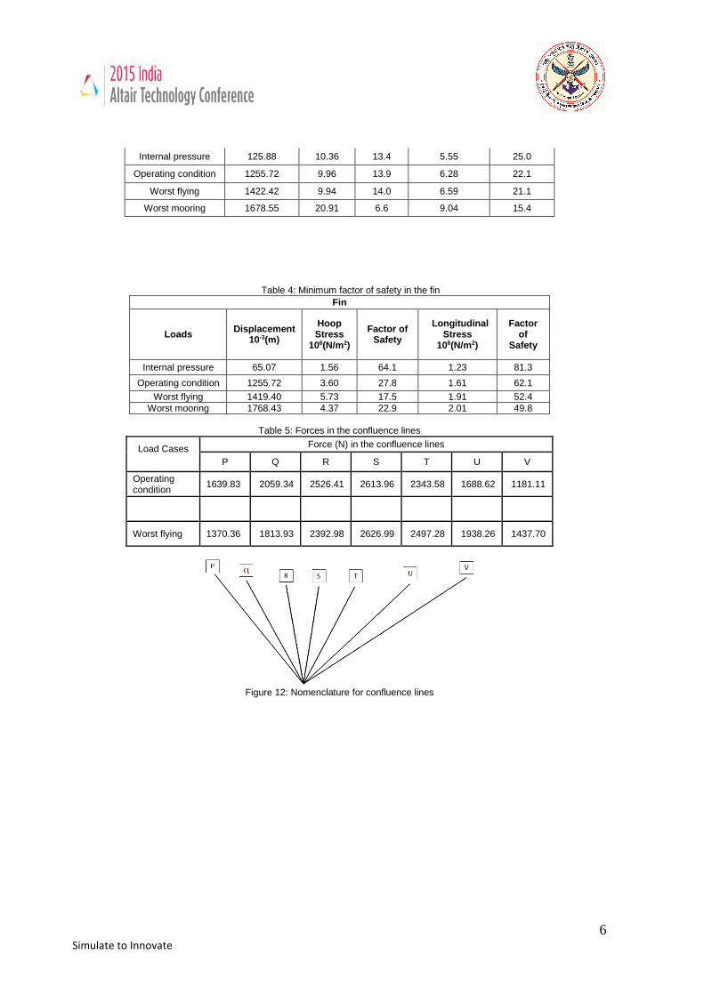
Table 5: Forces in the confluence lines
Load Cases
Force (N) in the confluence lines
P Q R S T U V
Operating condition
1639.83 2059.34 2526.41 2613.96 2343.58 1688.62 1181.11
Worst flying 1370.36 1813.93 2392.98 2626.99 2497.28 1938.26 1437.70
Figure 12: Nomenclature for confluence lines
7 Simulate to Innovate
Figure 8: Deformed shape of the aerostat
Figure 10: Fin Hoop Stress (106 N/m2)
Analysis concludes that Minimum factor of safety for Hull fabric is 6.6 5. Challenges
Stress analysis of flexible structures is very challenging & complex due to lack of bending stiffness. Aerostat structures are often subjected to large deformations.
6. Future Plans
Transient response dynamic analysis [III] will be carried out in future. 7. Conclusions
a) The finite element analysis is well suited for the overall structural analysis of flexible structures like aerostat.
b) Detailed geometric nonlinear analysis is essential to solve this type of problems. Linear static analysis gives misleading results.
c) Stresses observed in Hull & Fins for all load cases are well below the breaking strength. d) Stresses observed in the aerostat fabrics are within allowable limit & hence aerostat is safe. e) Balloons are subjected to variable environmental conditions. Static analysis cannot take into
account these conditions hence fatigue analysis could be carried out to ensure minimum duration survivability.
References
I. Hunt J. D, “Structural Analysis of Aerostat Flexible Structure by Finite Element Method”, AIAA, Report 81.1342, pp. 143-149, 1981.
II. Padmarajaiah, et al., “Structural Modeling and Analysis of 160 cu.m (SAC) Aerostat, Project Document ST 9915, NAL, Bangalore, 1999.
III. Hinton E., NAFEMS Introduction to Nonlinear Finite Element Analysis”, NAFEMS Brinihill East Kilbride, Glasgow, 1992.
Figure 9: Hull maximum displacement (10-3 m)
Fig. 11: Fin maximum displacement (10-3 m)