Embed Size (px)
Citation preview
Road Design Automated Plan Production Guide
_____________________________________________________________________ Louisiana Department of Transportation and Development
revised August 2008
1
INTRODUCTION 1.1 SCOPE
The primary purpose of this manual is to establish uniform policies and procedures to carry out the computer-aided drafting (CAD) functions of the Department of Transportation and Development. It is neither intended as, nor does it establish, a legal standard for these functions. The goal is to set basic CAD standards that will ensure a consistent CAD product within LA DOTD and facilitate the exchange of information. This document will also explain the many customizations developed by Road Design to assist in the plan preparation process. If used properly, these customizations will:
• Eliminate repetitive key ins • Reduce typographical errors • Supply commonly used items, i.e. cells, notes • Provide efficient methods of plan sheet development • Ensure standard appearance of plan sheets • Consolidate multi-task functions when possible
Standards given in this manual will be for the development of English projects only and are not intended to be static or all-inclusive. Updates and enhancements will be common occurrences as conditions and experience warrant. Suggestions for improvements to the manual and, more importantly to the processes described herein are encouraged. In this manner updates will reflect changes in software and hardware and, also, the input and desires of the Road Design CADD Users. As always, special situations may call for variation from these requirements. This manual is not intended to teach the basics of computer drafting and design. It is a guide to understanding and using MicroStation and InRoads along with the enhancements developed by Road Design, which are tailored for maximum productivity. If you need assistance with basic concepts, please refer to the MicroStation or InRoads “help” or other teaching aids. All processes can still be accomplished in the traditional manner. If, however, you choose not to avail yourself to the customizations, you will be deprived of their advantages, and unnecessarily increase plan preparation time.
Road Design Automated Plan Production Guide
_____________________________________________________________________ Louisiana Department of Transportation and Development
revised August 2008
2
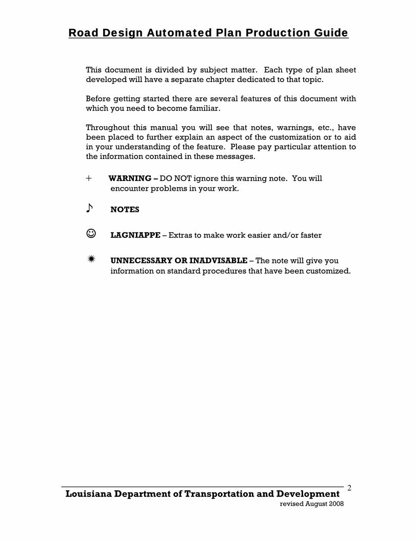
This document is divided by subject matter. Each type of plan sheet developed will have a separate chapter dedicated to that topic. Before getting started there are several features of this document with which you need to become familiar. Throughout this manual you will see that notes, warnings, etc., have been placed to further explain an aspect of the customization or to aid in your understanding of the feature. Please pay particular attention to the information contained in these messages.
+ WARNING – DO NOT ignore this warning note. You will encounter problems in your work.
♪ NOTES
☺ LAGNIAPPE – Extras to make work easier and/or faster
UNNECESSARY OR INADVISABLE – The note will give you information on standard procedures that have been customized.
Road Design Automated Plan Production Guide
_____________________________________________________________________ Louisiana Department of Transportation and Development
revised August 2008
3
STANDARDS AND ELECTRONIC DELIVERABLES
2.1 CAD STANDARDS
The following CAD standards assume that details are generated with MicroStation software, which is the LA DOTD standard; however, the standards shown have relevance for all CAD plans. See ”CONSULTANT REQUIREMENTS” below.
2.1.1 WORKSPACES LA DOTD has developed MicroStation Workspace Projects for various disciplines. These Workspace Projects are available for Consultants on the LA DOTD website at www.dotd.la.gov under “Doing Business With DOTD>Electronic Standards for Plans”
2.1.2 STANDARDS COMPLIANCE CERTIFICATION CAD requires an increased emphasis on the standardization of detailing practices. Factors such as text size, line style, line weight, level, color, element type, cells, sheet border, seed file, etc., all have to be considered. This complexity makes CAD standards a challenge to administer. LA DOTD now employs a tool that enables control of drafting standards to a high level. CADconform, an MDL application that runs in MicroStation, is customized to administer LA DOTD CAD standards. CADconform has tools that create standard features, draft using standard features, check for standards compliance and place stamps that certify drawings for standards compliance. This tool shall be used to ensure drafting efficiency and standards compliance. The CADconform software is available for Consultants and can be downloaded from the LA DOTD website at www.dotd.louisiana.gov under “Doing Business With DOTD>Electronic Standards for Plans.”
2.1.3 GENERAL CONSULTANT REQUIREMENTS LA DOTD has specific standards for software and deliverable formats used for plan production. These standards are published on the LA DOTD website at www.dotd.la.gov under “Doing Business With DOTD>Electronic Standards for Plans>Software Standards for Electronic Plans.”
Road Design Automated Plan Production Guide
_____________________________________________________________________ Louisiana Department of Transportation and Development
revised August 2008
4
The Consultant must obtain the latest CAD resources, Inroads Preference Files, CADconform software and CADconform standards dictionaries from the LA DOTD web site or request them from the Project Coordinator. CADconform software provides interactive help manuals including “Help on CADconform”, and “Help on LA DOTD”, which are supplementary to this manual. Consultants using AutoCAD are responsible for delivering MicroStation files. The consultant is responsible for translating the AutoCAD DWG file to the MicroStation DGN. The translated DGN file must certify as LA DOTD CAD standard compliant using CADconform software.
2.1.4 OUTPUT QUALITY - NEATNESS AND COMPOSITION CAD affords a great opportunity to produce neat, well-composed drawings. Details can be corrected, revised, rearranged, moved, copied, scaled, and rotated with little difficulty. Object corners can be precisely joined. Spacing between lines of text can be made consistent. Automated dimensioning enables consistent dimension styles. CADconform software makes it possible to tightly control symbology settings, which enables consistency in drawing appearance and readability. There is simply no excuse for shoddy work.
2.1.5 ACCURACY GUIDELINES CAD drawings are more valuable when they are accurately drawn. Precise angles and distances can be derived directly from CAD drawings without using manual or cogo computations. For this reason drawing geometry should be input with a minimum of four-decimal-place accuracy (feet) when possible. On the other hand, small design dimension changes or input errors sometime have ramifications to a drawing as a whole that would require a disproportionate amount of time to fix. In such cases, if there is no critical geometry to be derived from the drawing, corrections need not be made to the geometry. Conversely, if corrections to the accuracy of drawing geometry can be easily made, they should be made. In the past MicroStation was not able to generate drawings with geometric accuracy that approached those obtained with geometric programs such as COGO. Drawings created with MicroStation J or a later version should be sufficiently accurate
Road Design Automated Plan Production Guide
_____________________________________________________________________ Louisiana Department of Transportation and Development
revised August 2008
5
for most purposes. It is recommended practice to check critical layout geometry independently of MicroStation.
2.2 ELECTRONIC DELIVERABLES
If electronic deliverables are specified in the contract, then the following will be required: 2.2.1 ELECTRONIC DATA
Existing Topography:
A. Existing topography shall be submitted graphically in three-dimensional (3D) MicroStation (.dgn) format at a scale of 1’ = 1’ using a level structure consistent with the survey level structure.
B. All linear or curvilinear features shall be drawn at the
correct elevation using 3D line strings or 3D curve strings.
C. All linestyles shall be consistent with those contained in survey2000.rsc custom linestyle resource library.
D. All point symbols shall be placed using cells contained in
the survey07.cel cell file. Cells shall be placed at the correct elevation and at an active scale of 1 for a rural project or an active scale of 0.4 for an urban project.
E. Alignment and coordinate point data for all existing
features will also be will be submitted in InRoads alignment format (.alg).
Existing Ground Surface: The existing ground surface triangles shall be submitted graphically in 3D MicroStation format and either InRoads Digital Terrain Model (.dtm) format or ASCII (.dat) point files. The point files shall be in northing, easting and elevation format with separate files submitted for random, breakline, contour, interior and exterior points. Proposed Roadway:
A. Proposed roadway data shall be submitted graphically in MicroStation format at a scale of 1’ = 1’ and using a level structure consistent with the design level structure.
Road Design Automated Plan Production Guide
_____________________________________________________________________ Louisiana Department of Transportation and Development
revised August 2008
6
B. All linear or curvilinear features such shall be drawn at the
correct elevation using 3D line strings or 3D curve strings.
C. Proposed roadway alignment and coordinate point data will also be will be submitted in InRoads alignment format (.alg).
Proposed Roadway Surface: The proposed roadway surface shall be submitted graphically in three-dimensional MicroStation (.dgn) format and either InRoads Digital Terrain Model (.dtm) format or in ASCII (.dat) point files. The point files will be in northing, easting and elevation format and separate files shall be submitted for random, breakline, contour, interior and exterior points.
In addition to the above requirements the following requirements must also be met:
The global origin in the MicroStation files for the topographic layout, design layout and the digital terrain models must be the same and these files must be three-dimensional.
The Northing Easting coordinates in the alignment files
(.alg), the digital terrain model files (.dtm) and the ASCII point files (.dat) must coincide with each other and with the coordinates in the MicroStation Design files.
2.2.2 PLAN SHEETS
Border Layout: When plotted, the outside measure of each plan sheet shall be 22 x 34 inches with distance between margins measuring 21 x 31.5 inches. Top, bottom and right margins shall be 0.5 inch. Left margin shall be 2 inches.
Border Format: Sheet borders shall be as used by LA DOTD and are available for download our website in MicroStation (.dgn) format. Sheet borders can also be found on the Road Design server under /road/standards/new_English sheets. Borders shall not be changed, except that text in the block below the “DOTD” logo shall be replaced with the Consultant’s name or logo.
Road Design Automated Plan Production Guide
_____________________________________________________________________ Louisiana Department of Transportation and Development
revised August 2008
7
2.3 DIGITAL SUBMITTALS
All drawing submittals, starting with 60% Preliminary, shall be submitted in both hardcopy and digital format. CAD resources, such as sheet borders, cell files, color tables, font and linestyle resources, plotting resources, seed files and InRoads preference files, can be obtained from the project coordinator or are available for download on the LA DOTD website. The designer is responsible for ensuring that the latest available resources are being used.
Digital submittals shall be made on CD media and labeled, or uploaded to ProjectWise as instructed by the project coordinator. Labels shall include project number, parish, submittal stage (e.g., Final Plans), included sheet numbers, designer’s name and date. All CAD resources used for the project shall be included on the CD in a directory named “resources.” Model files (e.g., survey.dgn, design.dgn, profile.dgn) and sheet borders (e.g., blank.dgn, pp04.dgn, pp05.dgn) shall be attached as reference files to plan sheet files (e.g., sheet04.dgn, sheet05.dgn). These reference files are not attached by path and therefore must always reside in the same directory as the plan sheet files (See Section 3.6, Reference File Attachment, below). This relationship shall be maintained on the digital submittal CD.
♪ Only one plan sheet per file with the exception of cross sections will be accepted.
If the designer chooses to construct the drawings in another CAD format (e.g., AutoCAD/.dwg), and then translate the drawings to MicroStation format, the designer is responsible for ensuring that the translated drawings are complete and meet all LA DOTD CADD standards. Drawings shall be translated into standard MicroStation seed files using standard LA DOTD working units and color tables. All submittals starting with ACPs shall be plotted from the MicroStation files. The Department may request drawings in MicroStation format at any time. Translations will be at no additional cost to the Department.
2.4 PLOTTING
It is essential that digital drawings be submitted in a format that, when plotted using LA DOTD standard plotting techniques, produces identical output as produced by the Consultant’s plotting procedure.
Road Design Automated Plan Production Guide
_____________________________________________________________________ Louisiana Department of Transportation and Development
revised August 2008
8
To ensure identical outout, consultants are required to use Iplot software and DOTD standard Iplot settings files, pen tables and color tables. Additionally, DOTD standard MicroStation seed files shall be used.
Using special border plotting elements can facilitate consistently and efficiently producing drawings that are properly scaled with standard margins and plot labeling. Rectangles or cells can be used to facilitate proper scaling and margins. Text strings can be used as placeholders for border text to enable display of plot date, time and pathname. Such labeling can be accomplished using text substitution facilitated by variables defined in pen tables. The “Plot Border” level of LA DOTD standard border reference files is reserved for border plotting elements including plot-extents rectangles, and border text. The larger rectangle is for full-size plotting on 22 x 34-inch media. The smaller rectangle is for half-size plotting on 11 x 17 media. These elements may be useful to the Consultant as a plotting aid; however, they may not be compatible with certain output devices that the Consultant may be using. In any case, they shall not be modified in any way. The Consultant may modify plotting border elements on the Consultant Plot Border level as needed to achieve appropriate plotting results when plotting to internal output devices. This level shall be turned off w Consultants are not allowed to re-symbolize drawing elements using plotting software or the MicroStation “Level Symbology” tool.
Road Design Automated Plan Production Guide
_____________________________________________________________________ Louisiana Department of Transportation and Development
revised August 2008
9
DESIGN FILES 3.1 GLOBAL ORIGIN
Positioned within every MicroStation design file is a global origin. This origin serves as a reference from which all other elements are located. When using reference files, it is imperative that the same global origin be used in each model file (discussed in the next section) so that they will overlay with the correct relationship.
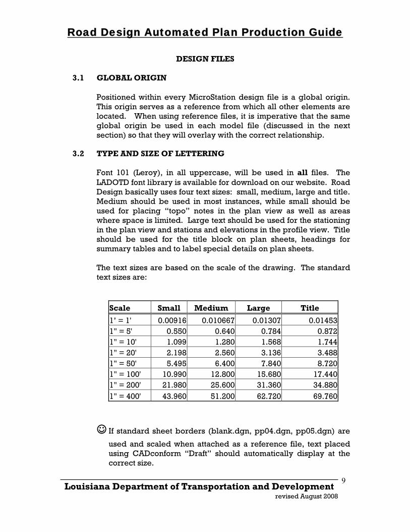
3.2 TYPE AND SIZE OF LETTERING Font 101 (Leroy), in all uppercase, will be used in all files. The LADOTD font library is available for download on our website. Road Design basically uses four text sizes: small, medium, large and title. Medium should be used in most instances, while small should be used for placing “topo” notes in the plan view as well as areas where space is limited. Large text should be used for the stationing in the plan view and stations and elevations in the profile view. Title should be used for the title block on plan sheets, headings for summary tables and to label special details on plan sheets.
The text sizes are based on the scale of the drawing. The standard text sizes are:
Scale Small Medium Large Title
1’ = 1' 0.00916 0.010667 0.01307 0.014531" = 5' 0.550 0.640 0.784 0.8721" = 10' 1.099 1.280 1.568 1.7441" = 20' 2.198 2.560 3.136 3.4881" = 50' 5.495 6.400 7.840 8.7201" = 100' 10.990 12.800 15.680 17.4401" = 200' 21.980 25.600 31.360 34.8801" = 400' 43.960 51.200 62.720 69.760
☺ If standard sheet borders (blank.dgn, pp04.dgn, pp05.dgn) are
used and scaled when attached as a reference file, text placed using CADconform “Draft” should automatically display at the correct size.
Road Design Automated Plan Production Guide
☺ InRoads preference files with correct text sizes and symbologies
are available for download on our website or can be found on the Road Design server under /road/standards/selectcad/ini/. “Civil20.ini” should be used for urban projects and “civil50.ini” should be used for rural projects.
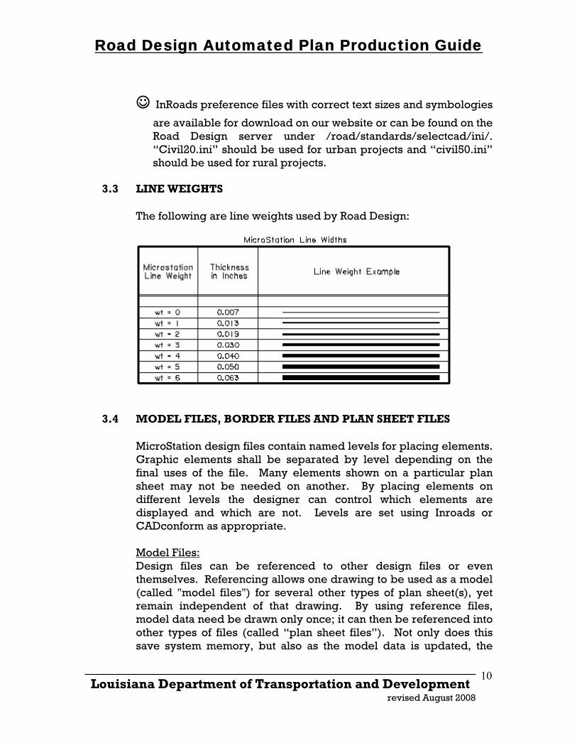
3.3 LINE WEIGHTS
The following are line weights used by Road Design:
3.4 MODEL FILES, BORDER FILES AND PLAN SHEET FILES
MicroStation design files contain named levels for placing elements. Graphic elements shall be separated by level depending on the final uses of the file. Many elements shown on a particular plan sheet may not be needed on another. By placing elements on different levels the designer can control which elements are displayed and which are not. Levels are set using Inroads or CADconform as appropriate. Model Files: Design files can be referenced to other design files or even themselves. Referencing allows one drawing to be used as a model (called "model files") for several other types of plan sheet(s), yet remain independent of that drawing. By using reference files, model data need be drawn only once; it can then be referenced into other types of files (called “plan sheet files”). Not only does this save system memory, but also as the model data is updated, the
_____________________________________________________________________ Louisiana Department of Transportation and Development
revised August 2008
10
Road Design Automated Plan Production Guide
_____________________________________________________________________ Louisiana Department of Transportation and Development
revised August 2008
11
changes are seen in the files referencing them. Use of reference files is an essential element of our electronic plan development process. Border Files: Border files are design files that display information for specific types of plan sheets. Road Design uses six different border sheets: a title sheet, a legend plan and profile sheet, a full plan and profile sheet, a summary of drainage structure sheet, a cross section sheet and a blank sheet. With the exception of the title sheet, all border files are used as reference files. Plan Sheet Files: The plan sheet files are the design files. or host files, for each particular sheet in a set of construction plans. These are the files from which the hard copy is plotted to produce a set of plans. Typically, the only elements in the sheet file are text pertinent to that plan sheet. All other data is referenced in from model files and border files.
3.5 REFERENCE FILE ATTACHMENT
Most plan sheet files will have model and border reference file attachments. When a reference file is attached, the full path to the directory in which the reference file resides is not retained by default in the attachment information that is stored in the active design file. This approach allows you to make portable reference file attachments. Portable reference files are attached so they can be located by MicroStation when:
They are accessed across a network The active design file and reference files are moved to a
different directory The active design file and reference files are transferred
to a system with a different directory structure
♪ “Portable” reference file attachments must reside in the same
folder as the design file that they are attached to.
∗ To facilitate the exchange of design files to other users (real estate, utilities, construction, legal) as the project develops, it is
Road Design Automated Plan Production Guide
_____________________________________________________________________ Louisiana Department of Transportation and Development
revised August 2008
12
imperative that ALL model, border and plan sheet files reside in the same project folder.
Use of the reference file “Save Full Path” toggle is not
recommended unless the reference file path is expected never to change.
3.6 FILE NAMING CONVENTION
The format of one plan sheet per design file shall be used for all plan sheets with the exception of cross sections. File names should indicate the plan sheet number. For example the design file with the title sheet would be named “sheet01.dgn”, the first typical section design file would be “sheet02.dgn” and the second typical section sheet file would be “sheet02a.dgn”, and so on. The model files to be used as reference files for plan sheet set up shall be named as follows: Model Files:
topo.dgn- existing topographic information design.dgn- proposed roadway information profile.dgn- proposed profile information exdrain.dgn- existing drainage information ddrain.dgn- design drainage information xsec.dgn –proposed cross sections
∗ All model files must be three-dimensional files with the same global origin.
Border Files:
title.dgn - title sheet at a 1’ = 1’ scale blank.dgn - blank sheet at a 1’ = 1’ scale pp04.dgn - legend plan and profile sheet at a 1’ = 1’ scale pp05.dgn – full plan and profile sheet at a 1’ = 1’ scale sumdrain.dgn - drainage structure sheet at a 1’ = 1’ scale 5xsec.dgn – 50 cross section sheets at 1” = 5’ scale 10sec.dgn – 50 cross section sheets at 1” = 10’ scale
When beginning a new project, select the appropriate sheet borders from /road/standards/new_English sheets/ on the Road Design server and copy them to your project folder. Sheet borders can also be downloaded from the LA DOTD website. Copy the
Road Design Automated Plan Production Guide
_____________________________________________________________________ Louisiana Department of Transportation and Development
revised August 2008
13
appropriate border files to your project folder. They can then be attached as reference files to the plan sheet files. ♪ All sheet borders are placed with the lower left corner of the
sheet at an origin of 0,0. With the exception of cross section sheets, all sheet borders are drawn at a 1’ = 1’ scale and should be scaled in the reference file attachment. When scaling the reference file use the origin 0,0 as the point to scale about.
☺ Cross section sheet borders are pre-scaled and InRoads
preference files for displaying to these files are available for download on the website. Generally 5xsec.dgn is used for urban projects and 10xsec.dgn is use for rural projects. Fifty sheets are provided in each file. If more are needed simply copy additional sheets after sheet 50 taking care to maintain the same distance between the lower left corner of each sheet.
Road Design Automated Plan Production Guide
_____________________________________________________________________ Louisiana Department of Transportation and Development
revised August 2008
14
PLAN AND PROFILE SHEETS
4.1 DRAWING SCALE AND SHEET SETUP
Typically the following scales are used when setting up plan and profile sheets: • 1” = 20’ horizontal and 1” = 4’ vertical scale - urban areas • 1” = 50’ horizontal and 1” = 10’ vertical scale - rural areas On the first plan and profile sheet (sheet04.dgn) the left half of the sheet is used for a legend in the plan view and general construction notes in the profile view. The right half is used for the beginning of the project in the plan and profile views. This sheet will have a maximum of 300’ and 900’ for a 1” = 20’ and 1” = 50’ scale respectively. All other sheets (sheet05.dgn, sheet06.dgn, etc.) will be full sheets with a maximum of 500’ and 1300’ for a 1” = 20’ and 1” = 50’ scale respectively.
4.2 MODEL FILES AND SHEET BORDER FILES
Plan and profile sheets are created using the InRoads Plan and Profile Sheet Generator. The sheets created may be plan views, plan and profile view or profiles only. Data for the plan view will be referenced from graphics displayed in your survey and design model files (see Section 2.3). The survey file should be a copy of the original survey file and should have all text removed.
☺ Surveys provided by the LA DOTD Location and Survey
section should have a file called “notext.dgn” which as the name indicates has had all of the text removed.
The “Design” file (design.dgn) is a new file created by the user and is to be used to display all design line work and symbols in the plan view. The only text that should be displayed in this file is the centerline stationing and cardinal points. All other text should be placed in the plan sheet files. Data for the profile view will be referenced from graphics displayed in your profile file. The profile file (profile.dgn) is also a new file
Road Design Automated Plan Production Guide
_____________________________________________________________________ Louisiana Department of Transportation and Development
revised August 2008
15
created by the user and is used to interactively display the data for the profile views as the sheet generator is run.
∗ The survey, design and profile files must be three-
dimensional and the design and profile files must have the same global origin as the survey file.
♪ The best way we have found to create the design and profile
files is to make a copy of the survey file, turn on all levels, delete all elements and compress the file. Once this is done, attach the road.tbl color table, the rdraft.cel cell file, either the design.lvl or profile.lvl level structure files and save settings.
Sheet border files (pp04.dgn, pp05.dgn) are available on our website. The files can also be found on the Road Design server under /road/standards/new_English sheets/. The sheet border files are drawn at a 1’ = 1’ scale. ♪ When using the Plan and Profile Sheet Generator, sheet
border files will be attached as a reference file. The scale of the reference file will be 12 x the scale of the drawing. For example for a 1” = 20’ scale drawing the reference file scale will be 12 x 20 = 240.
∗ When using the Plan and Profile Sheet Generator, the lower
left corner of the sheet must be located at origin 0,0 therefore, DO NOT move the sheet from its location in the design file.
4.3 SEED FILE
Before using the Plan and Profile Sheet Generator you will need to create a MicroStation seed file that will be used to set the design file parameters for each new plan sheet file, or host file, that is created. As with the design and profile files, the seed file must be three-dimensional and must have the same global origin as the survey file; therefore, should be created the same way. Because this seed file will be used to set parameters in each plan and profile sheet file you might want to: attach the “road.tbl” color table, attach the rdraft.cel cell file and set the active cell scale (as=240, urban, as=600 rural) then save settings.
Road Design Automated Plan Production Guide
_____________________________________________________________________ Louisiana Department of Transportation and Development
revised August 2008
16
4.4 PLAN AND PROFILE SHEET GENERATOR
This section assumes that the designer is familiar with InRoads and the Plan and Profile Sheet Generator. The following is an explanation of how to set up and display the plan and profile sheets using the sheet generator along with preferences developed by LA DOTD.
☺ Preference files with these customization, civil20.ini and
civil50.ini, are available for download on our website. The files can also be found in the Road Design workspace under \Workspace\Standards\ini.
First of all it is important for the designer to understand that because we use two separate sheet borders (pp04 with legend and pp05 without legend) we will have to set up the first plan and profile sheet separately from the remainder of the sheets. This explanation will discuss setting up the remaining sheets, beginning with sheet05. There will then be a brief explanation at the end on how to set up sheet04. In the preference files provided by LADOTD, we have “preset” as many settings as possible. This explanation will take you through each of the tabs on the sheet generator and discuss specific things that will have to be set by the user for the sheets to generate properly.
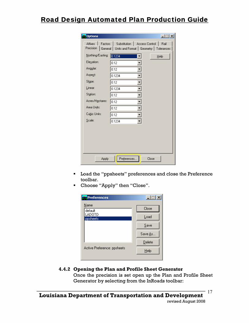
4.4.1 Getting Started Start MicroStation and open your profile.dgn design file. After starting InRoads, open your existing ground surface and design alignment file. Set your design centerline as active. Because the border sheets are a 1’ = 1’ scale and will be scaled up when the sheets are generated it is necessary to set the precision of several system parameters in InRoads to at least four decimal places. This has been preset in the preference files and can be loaded by selecting from InRoads toolbar:
Tools>Options> Under the “Precision Tab”, select “Preferences”
Road Design Automated Plan Production Guide
Load the “ppsheets” preferences and close the Preference toolbar.
Choose “Apply” then “Close”.
4.4.2 Opening the Plan and Profile Sheet Generator Once the precision is set open up the Plan and Profile Sheet Generator by selecting from the InRoads toolbar:
_____________________________________________________________________ Louisiana Department of Transportation and Development
revised August 2008
17
Road Design Automated Plan Production Guide
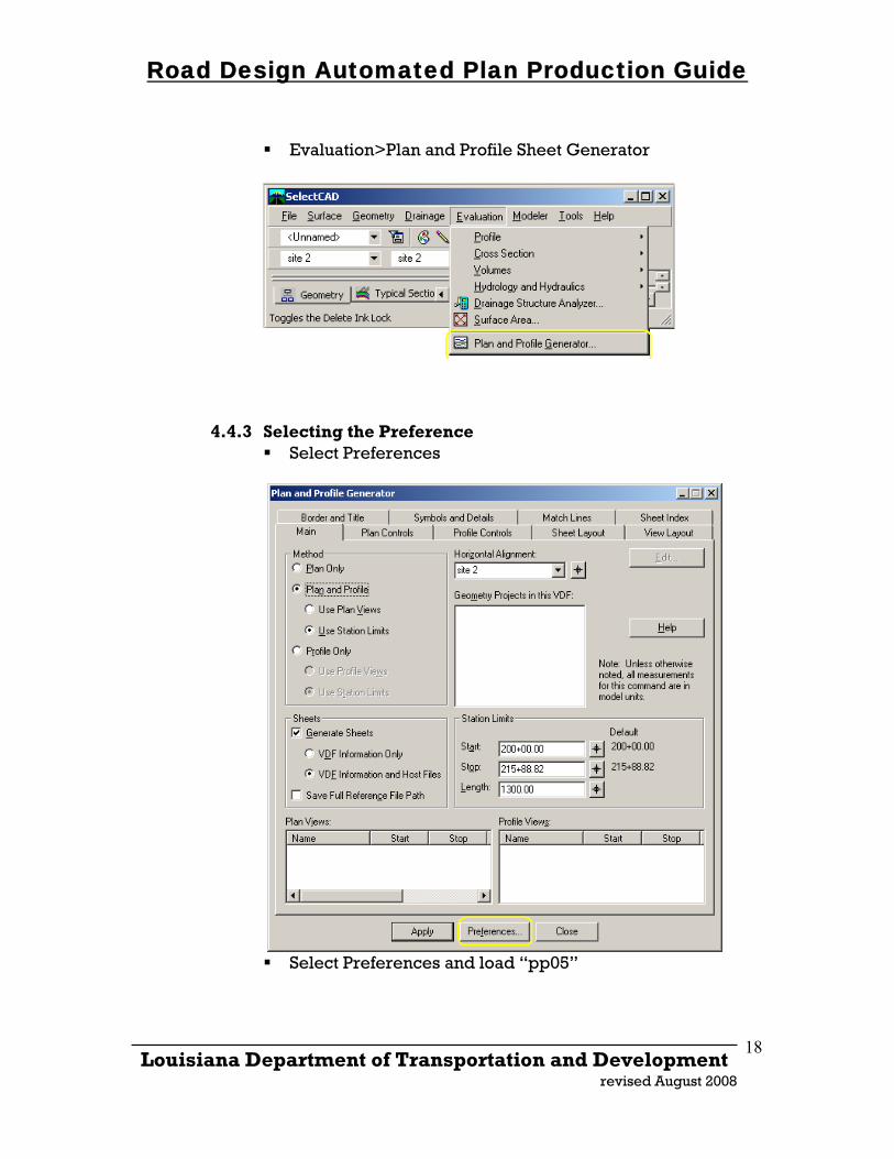
Evaluation>Plan and Profile Sheet Generator
4.4.3 Selecting the Preference
Select Preferences
Select Preferences and load “pp05”
_____________________________________________________________________ Louisiana Department of Transportation and Development
revised August 2008
18
Road Design Automated Plan Production Guide
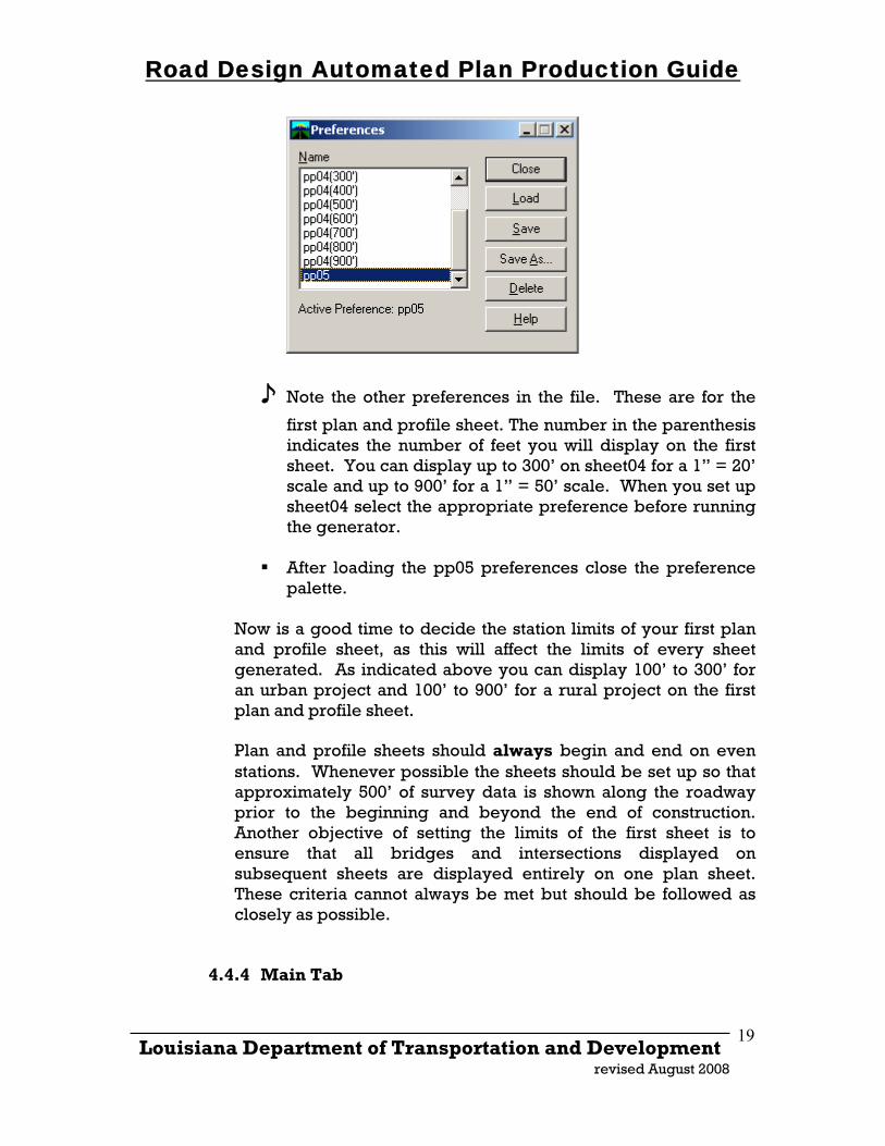
♪ Note the other preferences in the file. These are for the
first plan and profile sheet. The number in the parenthesis indicates the number of feet you will display on the first sheet. You can display up to 300’ on sheet04 for a 1” = 20’ scale and up to 900’ for a 1” = 50’ scale. When you set up sheet04 select the appropriate preference before running the generator.
After loading the pp05 preferences close the preference
palette.
Now is a good time to decide the station limits of your first plan and profile sheet, as this will affect the limits of every sheet generated. As indicated above you can display 100’ to 300’ for an urban project and 100’ to 900’ for a rural project on the first plan and profile sheet. Plan and profile sheets should always begin and end on even stations. Whenever possible the sheets should be set up so that approximately 500’ of survey data is shown along the roadway prior to the beginning and beyond the end of construction. Another objective of setting the limits of the first sheet is to ensure that all bridges and intersections displayed on subsequent sheets are displayed entirely on one plan sheet. These criteria cannot always be met but should be followed as closely as possible.
4.4.4 Main Tab
_____________________________________________________________________ Louisiana Department of Transportation and Development
revised August 2008
19
Road Design Automated Plan Production Guide
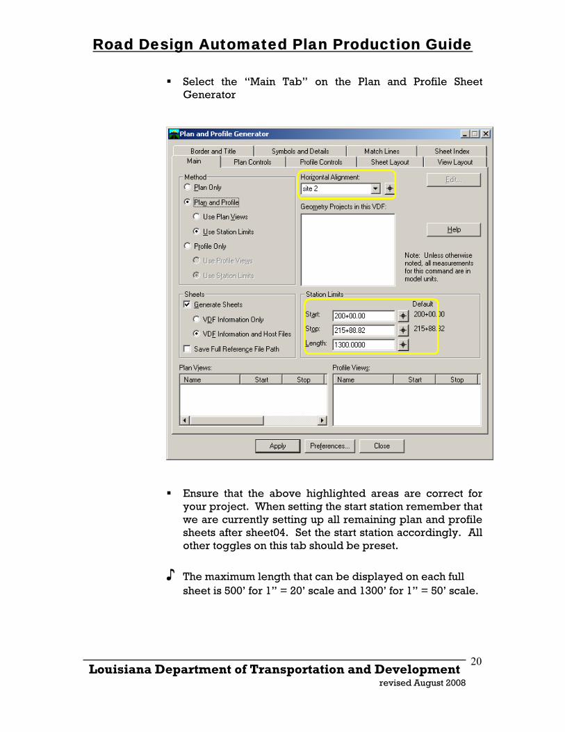
Select the “Main Tab” on the Plan and Profile Sheet Generator
Ensure that the above highlighted areas are correct for your project. When setting the start station remember that we are currently setting up all remaining plan and profile sheets after sheet04. Set the start station accordingly. All other toggles on this tab should be preset.
♪ The maximum length that can be displayed on each full sheet is 500’ for 1” = 20’ scale and 1300’ for 1” = 50’ scale.
_____________________________________________________________________ Louisiana Department of Transportation and Development
revised August 2008
20
Road Design Automated Plan Production Guide
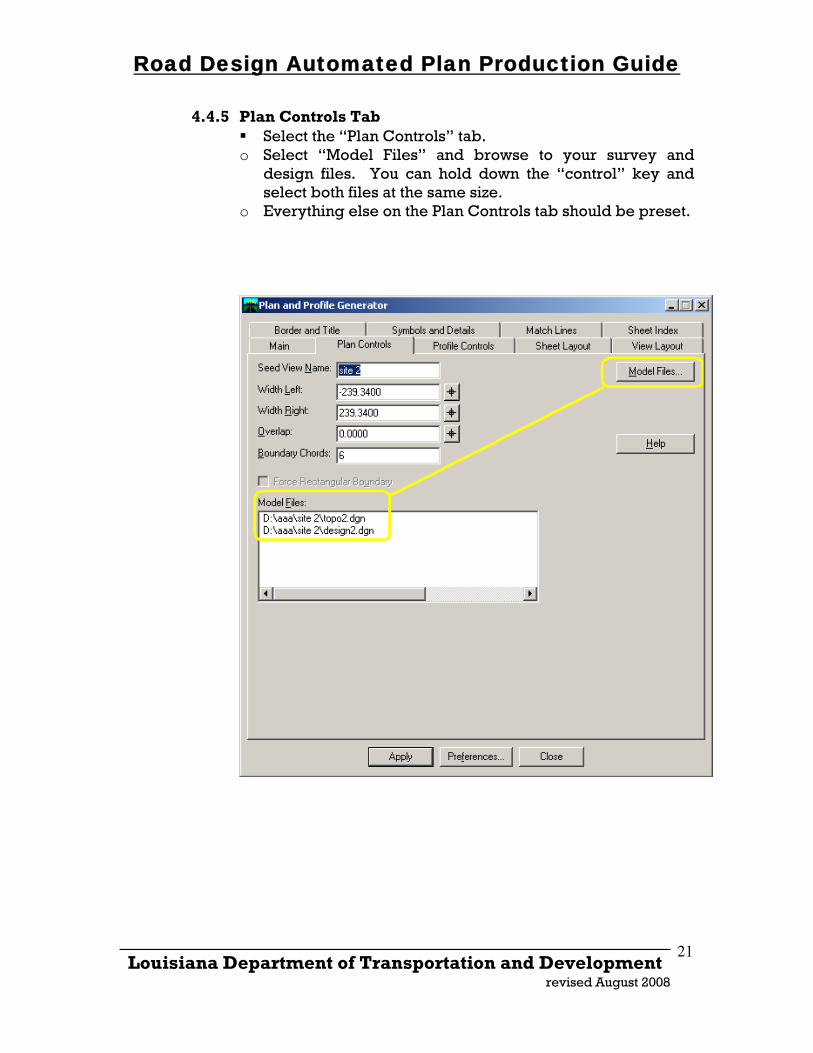
4.4.5 Plan Controls Tab Select the “Plan Controls” tab.
o Select “Model Files” and browse to your survey and design files. You can hold down the “control” key and select both files at the same size.
o Everything else on the Plan Controls tab should be preset.
_____________________________________________________________________ Louisiana Department of Transportation and Development
revised August 2008
21
Road Design Automated Plan Production Guide
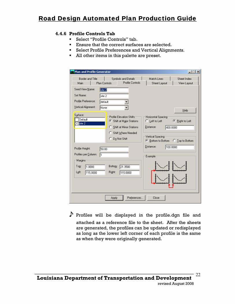
4.4.6 Profile Controls Tab Select “Profile Controls” tab. Ensure that the correct surfaces are selected. Select Profile Preferences and Vertical Alignments. All other items in this palette are preset.
♪ Profiles will be displayed in the profile.dgn file and
attached as a reference file to the sheet. After the sheets are generated, the profiles can be updated or redisplayed as long as the lower left corner of each profile is the same as when they were originally generated.
_____________________________________________________________________ Louisiana Department of Transportation and Development
revised August 2008
22
Road Design Automated Plan Production Guide
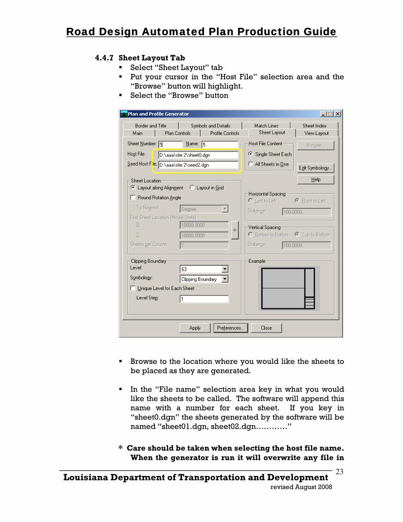
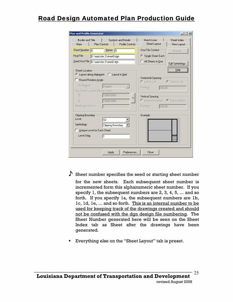
4.4.7 Sheet Layout Tab Select “Sheet Layout” tab Put your cursor in the “Host File” selection area and the
“Browse” button will highlight. Select the “Browse” button
Browse to the location where you would like the sheets to
be placed as they are generated. In the “File name” selection area key in what you would
like the sheets to be called. The software will append this name with a number for each sheet. If you key in “sheet0.dgn” the sheets generated by the software will be named “sheet01.dgn, sheet02.dgn…………”
∗ Care should be taken when selecting the host file name. When the generator is run it will overwrite any file in
_____________________________________________________________________ Louisiana Department of Transportation and Development
revised August 2008
23
Road Design Automated Plan Production Guide
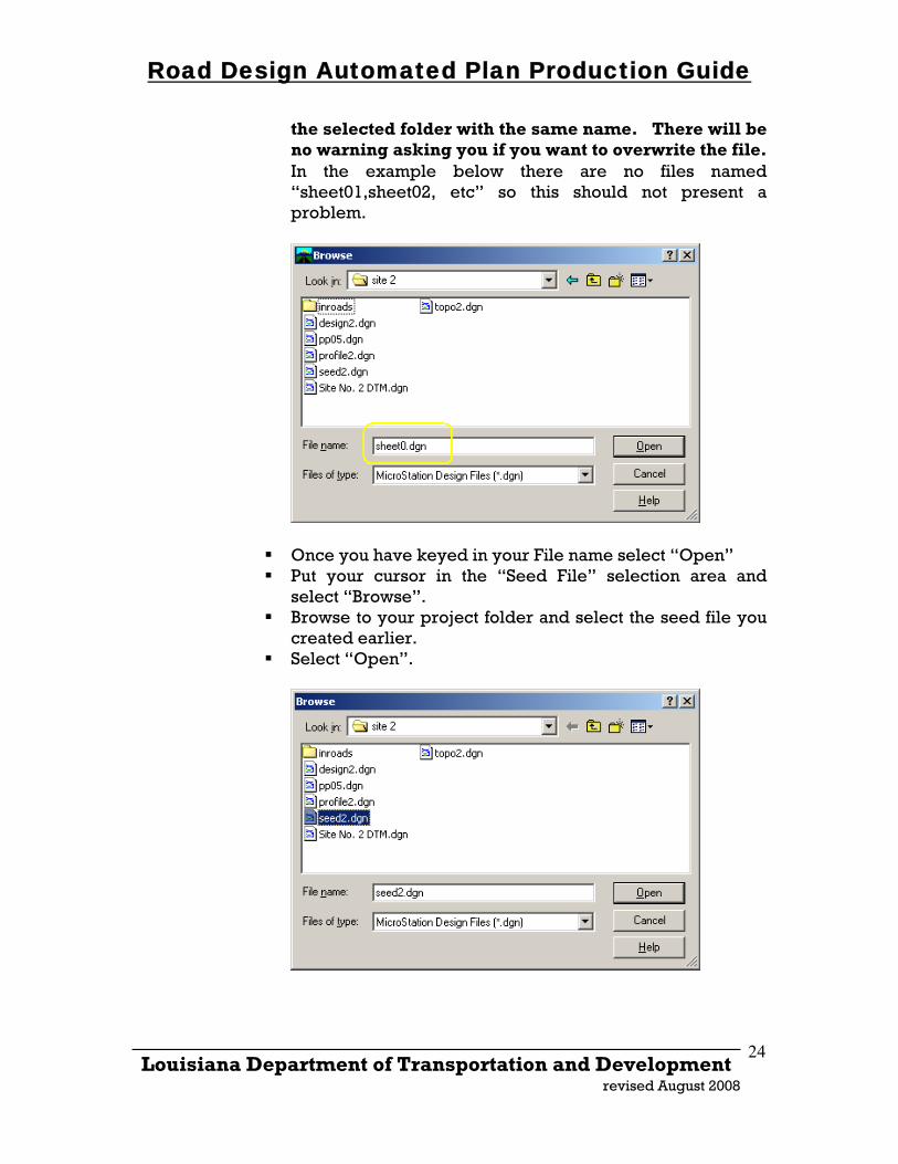
the selected folder with the same name. There will be no warning asking you if you want to overwrite the file. In the example below there are no files named “sheet01,sheet02, etc” so this should not present a problem.
Once you have keyed in your File name select “Open” Put your cursor in the “Seed File” selection area and
select “Browse”. Browse to your project folder and select the seed file you
created earlier. Select “Open”.
_____________________________________________________________________ Louisiana Department of Transportation and Development
revised August 2008
24
Road Design Automated Plan Production Guide
♪ Sheet number specifies the seed or starting sheet number
for the new sheets. Each subsequent sheet number is incremented form this alphanumeric sheet number. If you specify 1, the subsequent numbers are 2, 3, 4, 5, ... and so forth. If you specify 1a, the subsequent numbers are 1b, 1c, 1d, 1e, ... and so forth. This is an internal number to be used for keeping track of the drawings created and should not be confused with the dgn design file numbering. The Sheet Number generated here will be seen on the Sheet Index tab as Sheet after the drawings have been generated.
Everything else on the “Sheet Layout” tab is preset.
_____________________________________________________________________ Louisiana Department of Transportation and Development
revised August 2008
25
Road Design Automated Plan Production Guide
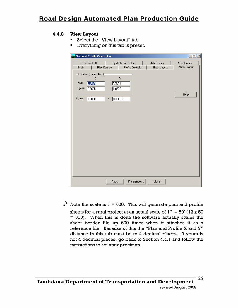
4.4.8 View Layout Select the “View Layout” tab Everything on this tab is preset.
♪ Note the scale is 1 = 600. This will generate plan and profile
sheets for a rural project at an actual scale of 1” = 50’ (12 x 50 = 600). When this is done the software actually scales the sheet border file up 600 times when it attaches it as a reference file. Because of this the “Plan and Profile X and Y” distance in this tab must be to 4 decimal places. If yours is not 4 decimal places, go back to Section 4.4.1 and follow the instructions to set your precision.
_____________________________________________________________________ Louisiana Department of Transportation and Development
revised August 2008
26
Road Design Automated Plan Production Guide
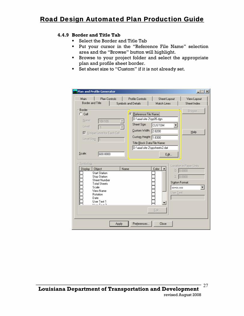
4.4.9 Border and Title Tab Select the Border and Title Tab Put your cursor in the “Reference File Name” selection
area and the “Browse” button will highlight. Browse to your project folder and select the appropriate
plan and profile sheet border. Set sheet size to “Custom” if it is not already set.
_____________________________________________________________________ Louisiana Department of Transportation and Development
revised August 2008
27
Road Design Automated Plan Production Guide
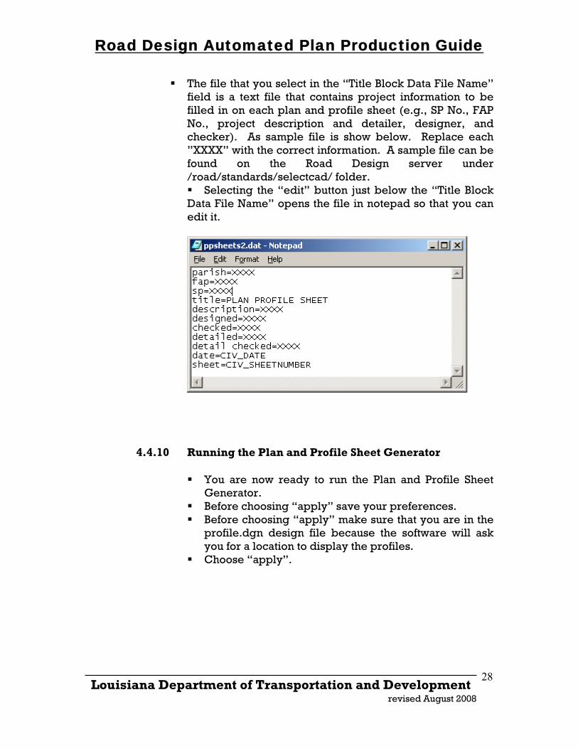
The file that you select in the “Title Block Data File Name” field is a text file that contains project information to be filled in on each plan and profile sheet (e.g., SP No., FAP No., project description and detailer, designer, and checker). As sample file is show below. Replace each ”XXXX” with the correct information. A sample file can be found on the Road Design server under /road/standards/selectcad/ folder. Selecting the “edit” button just below the “Title Block
Data File Name” opens the file in notepad so that you can edit it.
4.4.10 Running the Plan and Profile Sheet Generator
You are now ready to run the Plan and Profile Sheet Generator.
Before choosing “apply” save your preferences. Before choosing “apply” make sure that you are in the
profile.dgn design file because the software will ask you for a location to display the profiles.
Choose “apply”.
_____________________________________________________________________ Louisiana Department of Transportation and Development
revised August 2008
28
Road Design Automated Plan Production Guide
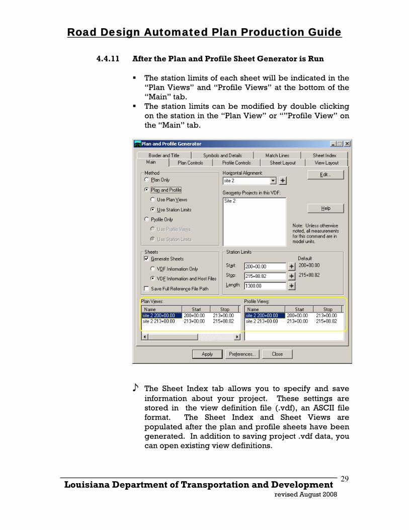
4.4.11 After the Plan and Profile Sheet Generator is Run
The station limits of each sheet will be indicated in the “Plan Views” and “Profile Views” at the bottom of the “Main” tab.
The station limits can be modified by double clicking on the station in the “Plan View” or “”Profile View” on the “Main” tab.
♪ The Sheet Index tab allows you to specify and save information about your project. These settings are stored in the view definition file (.vdf), an ASCII file format. The Sheet Index and Sheet Views are populated after the plan and profile sheets have been generated. In addition to saving project .vdf data, you can open existing view definitions.
_____________________________________________________________________ Louisiana Department of Transportation and Development
revised August 2008
29
Road Design Automated Plan Production Guide
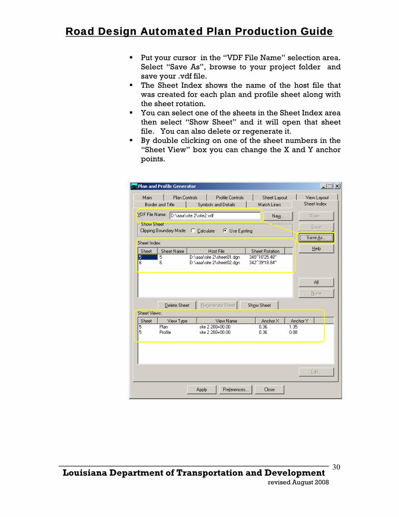
Put your cursor in the “VDF File Name” selection area. Select “Save As”, browse to your project folder and save your .vdf file.
The Sheet Index shows the name of the host file that was created for each plan and profile sheet along with the sheet rotation.
You can select one of the sheets in the Sheet Index area then select “Show Sheet” and it will open that sheet file. You can also delete or regenerate it.
By double clicking on one of the sheet numbers in the “Sheet View” box you can change the X and Y anchor points.
_____________________________________________________________________ Louisiana Department of Transportation and Development
revised August 2008
30
Road Design Automated Plan Production Guide
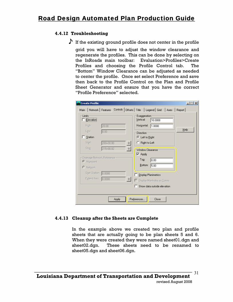
4.4.12 Troubleshooting
♪ If the existing ground profile does not center in the profile
grid you will have to adjust the window clearance and regenerate the profiles. This can be done by selecting on the InRoads main toolbar: Evaluation>Profiles>Create Profiles and choosing the Profile Control tab. The “Bottom” Window Clearance can be adjusted as needed to center the profile. Once set select Preference and save then back to the Profile Control on the Plan and Profile Sheet Generator and ensure that you have the correct “Profile Preference” selected.
4.4.13 Cleanup after the Sheets are Complete
In the example above we created two plan and profile sheets that are actually going to be plan sheets 5 and 6. When they were created they were named sheet01.dgn and sheet02.dgn. These sheets need to be renamed to sheet05.dgn and sheet06.dgn.
_____________________________________________________________________ Louisiana Department of Transportation and Development
revised August 2008
31
Road Design Automated Plan Production Guide
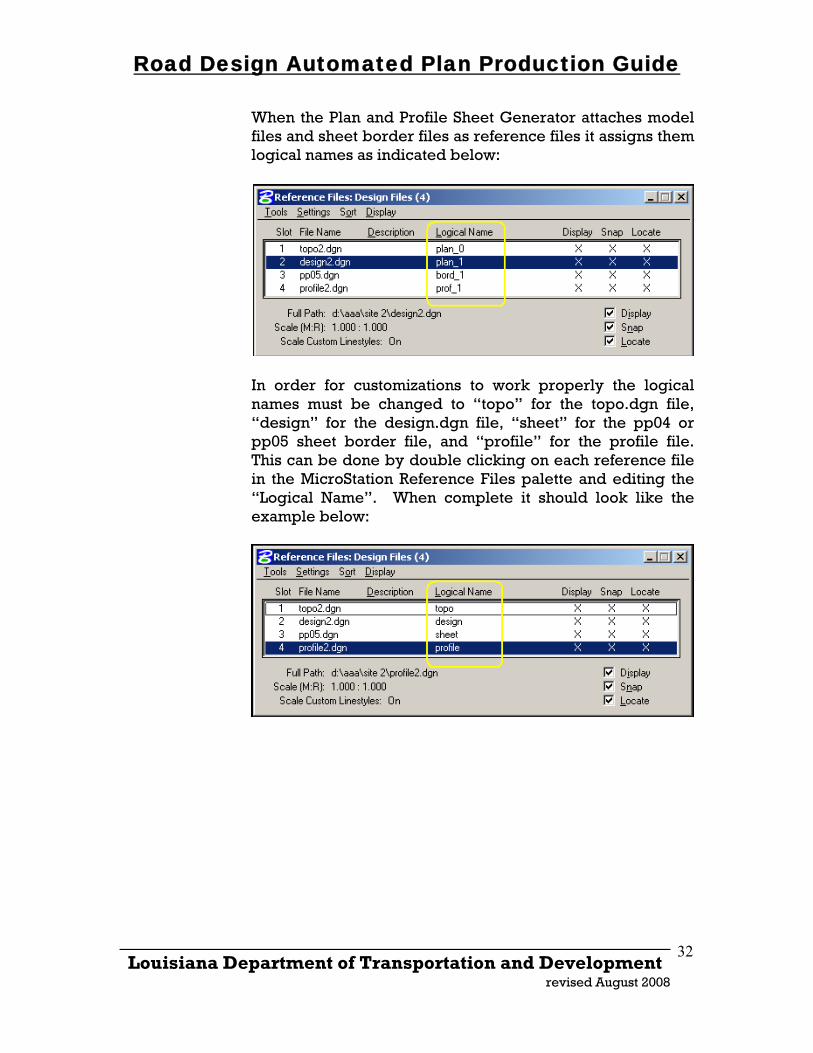
When the Plan and Profile Sheet Generator attaches model files and sheet border files as reference files it assigns them logical names as indicated below:
In order for customizations to work properly the logical names must be changed to “topo” for the topo.dgn file, “design” for the design.dgn file, “sheet” for the pp04 or pp05 sheet border file, and “profile” for the profile file. This can be done by double clicking on each reference file in the MicroStation Reference Files palette and editing the “Logical Name”. When complete it should look like the example below:
_____________________________________________________________________ Louisiana Department of Transportation and Development
revised August 2008
32
Road Design Automated Plan Production Guide
_____________________________________________________________________ Louisiana Department of Transportation and Development
revised August 2008
33
4.5 PLAN AND PROFILE SHEET DRAFTING CADconform Dictionaries have been set up in CADconform to assist in drafting and detailing of plan and profile sheets. Cells have been created for standard symbols and notes that are routinely placed on plan and profile sheets. The cells can be found in “rdraft.cel” and are created at a 1’ = 1’ scale.
∗ When using CADconform to place notes or cells, you must set your MicroStation active cell scale to 12 x the scale of your drawing unless the scale of your drawing is 1’ = 1’. For example, if you are detailing a plan and profile sheet that is to be plotted at a 1” = 50’ scale set your active scale to 12 x 50 = 600.
Road Design Automated Plan Production Guide
Miscellaneous Workflows
Annotating Required R/W Station and Offsets using Tracking:
The following procedure has been developed to place the right-of-way maker and annotate station and offsets for required right-of-way on plan and profile sheets using InRoads tracking feature.
• Start InRoads and ensure that your proposed alignment is active. • Load civil20.ini or civil50.ini. The symbologies and preferences to
annotate this were added to the preference files on 11/08/02 so ensure that you have the latest copy.
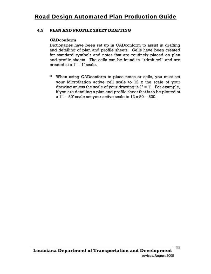
• Ensure that the “inroad.cel” cell file is active in Microstation • On the InRoads menubar select “Options”
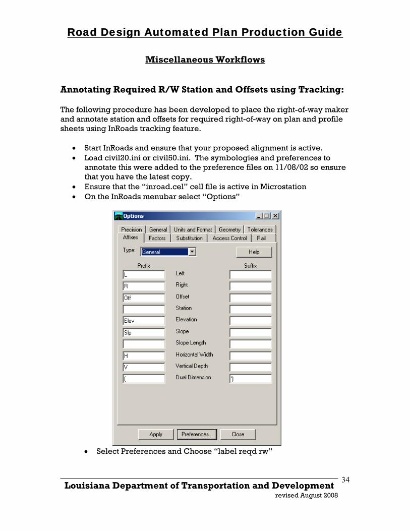
• Select Preferences and Choose “label reqd rw”
_____________________________________________________________________ Louisiana Department of Transportation and Development
revised August 2008
34
Road Design Automated Plan Production Guide
• Select the “Affixes” tab and ensure your “General” type looks as below
• On the InRoads menubar select “Tracking.” From the tracking
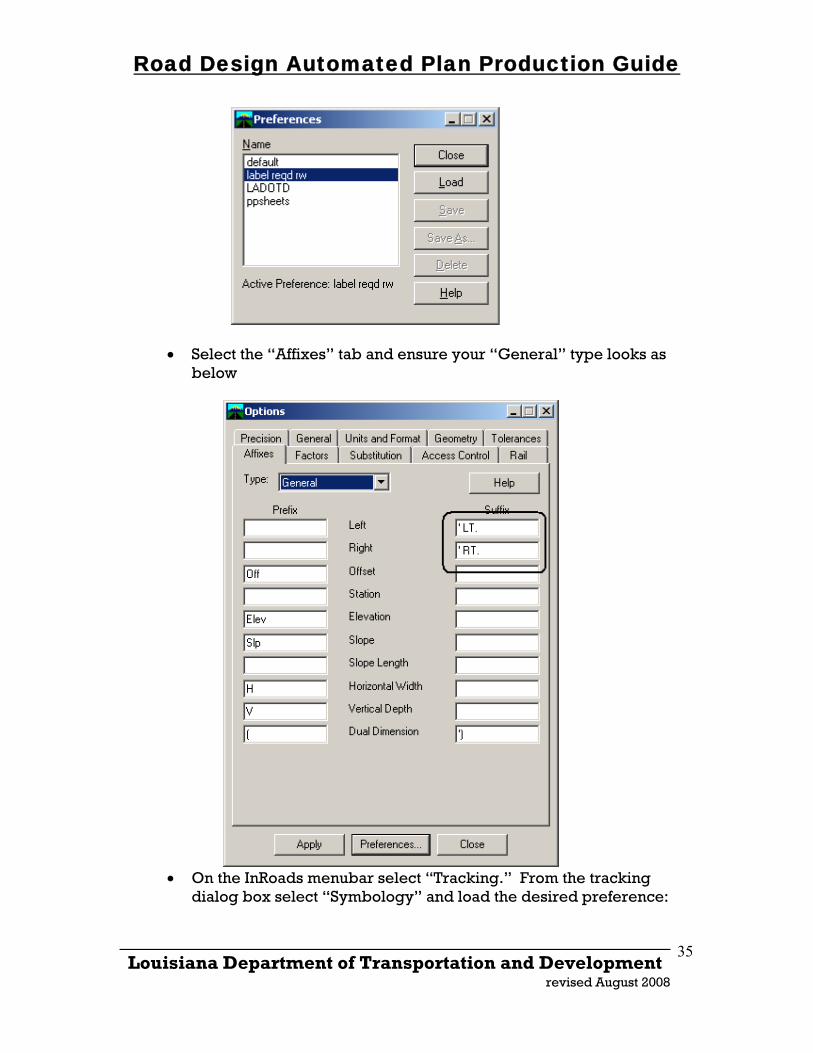
dialog box select “Symbology” and load the desired preference:
_____________________________________________________________________ Louisiana Department of Transportation and Development
revised August 2008
35
Road Design Automated Plan Production Guide
• On the tracking palette turn off all toggles but station and offset:
_____________________________________________________________________ Louisiana Department of Transportation and Development
revised August 2008
36
Road Design Automated Plan Production Guide
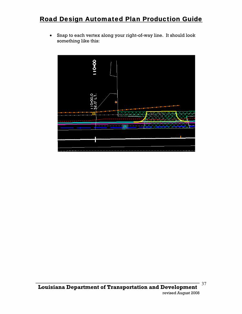
• Snap to each vertex along your right-of-way line. It should look something like this:
_____________________________________________________________________ Louisiana Department of Transportation and Development
revised August 2008
37
Road Design Automated Plan Production Guide
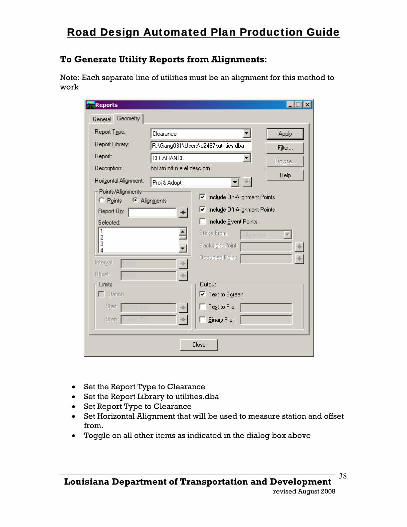
To Generate Utility Reports from Alignments: Note: Each separate line of utilities must be an alignment for this method to work
• Set the Report Type to Clearance • Set the Report Library to utilities.dba • Set Report Type to Clearance • Set Horizontal Alignment that will be used to measure station and offset
from. • Toggle on all other items as indicated in the dialog box above
_____________________________________________________________________ Louisiana Department of Transportation and Development
revised August 2008
38
Road Design Automated Plan Production Guide
_____________________________________________________________________
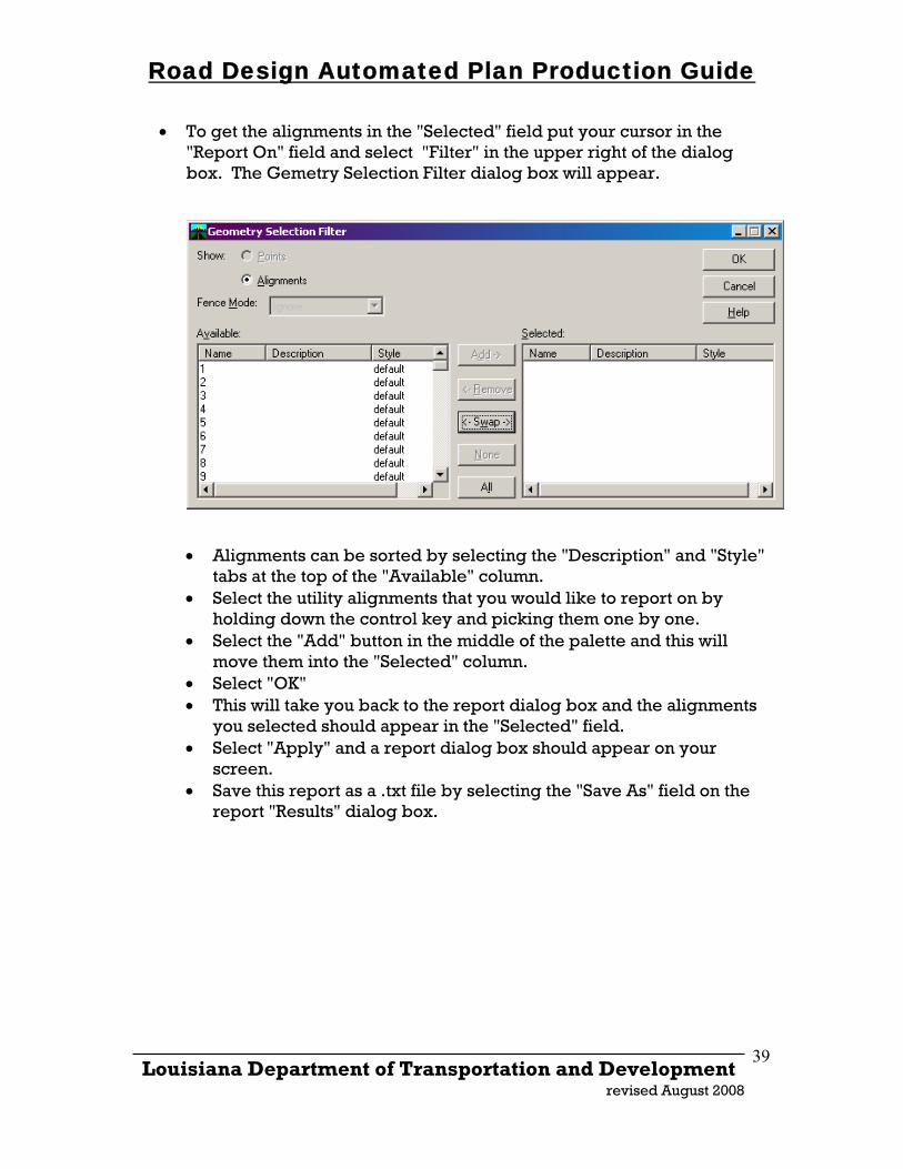
• To get the alignments in the "Selected" field put your cursor in the "Report On" field and select "Filter" in the upper right of the dialog box. The Gemetry Selection Filter dialog box will appear.
• Alignments can be sorted by selecting the "Description" and "Style" tabs at the top of the "Available" column.
• Select the utility alignments that you would like to report on by holding down the control key and picking them one by one.
• Select the "Add" button in the middle of the palette and this will move them into the "Selected" column.
• Select "OK" • This will take you back to the report dialog box and the alignments
you selected should appear in the "Selected" field. • Select "Apply" and a report dialog box should appear on your
screen. • Save this report as a .txt file by selecting the "Save As" field on the
report "Results" dialog box.
Louisiana Department of Transportation and Development
revised August 2008
39