Embed Size (px)
Citation preview
ROADSIDE DITCH DESIGN AND EROSION CONTROL
ON VIRGINIA HIGHWAYS
by
Sheila L. Stallings
Thesis submitted to the Faculty of the
Virginia Polytechnic Institute and State University
in partial fulfillment of the requirements for the degree of
Masters of Science
in
Civil Engineering
Dr. Panos Diplas, Chairman
Dr. G.V. Loganathan
Dr. David F. Kibler
September 17, 1999
Blacksburg, Virginia
Roadside Ditch Design and Erosion Control on Virginia Highways
by
Sheila L. Stallings
ABSTRACT
The state of roadside ditch design and performance has become a topic of concern for the
Virginia Department of Transportation. Erosion failures of roadside ditches have occurred
frequently enough to indicate that it may be desirable to revise the current design practice.
Through the Virginia Transportation Research Council, VDOT has sponsored this research to
investigate the state of design practice for these structures and to explore revisions to the design
process resulting in a more economical design.
To investigate the erosion problems, various VDOT personnel at each of Virginia’s nine
Construction Districts were interviewed with the intent to gain an understanding of roadside
ditch performance in each District. When possible, field visits were made to sites experiencing
erosion failure and soil samples were collected for analysis. In addition, experiences and design
procedures in neighboring states were reviewed, with the objective of determining if similar
problems have been experienced, and if so, how they have been addressed. The survey of other
states included nine states, and a site visit to the Mount Airy District of the North Carolina
Department of Transportation. A study of the literature relating to the hydraulic performance of
unlined and lined ditches was also performed, with the objective of researching available
stability criteria used in ditch design and determining if suitable values of Manning's n are being
used in Virginia design.
The results of this study presented in this thesis represent the best recommended roadside
ditch design practice based on current available research. Recommendations include revisions to
the current relationship of soil type and maximum allowable velocity, revisions to the application
of Manning’s n for various lining conditions, and suggestions to improve the overall design and
construction process based on surveyed VDOT experience, surrounding states and current
research. Future research will be necessary to improve the scientific bases for these
recommendations.
iii
Acknowledgements
I would like to thank Dr. Diplas for serving as my advisor. His guidance, advice, and
patience were invaluable. I would also like to thank Dr. G.V. Loganathan and Dr. David Kibler
for serving as members of my committee and offering suggestions and advice. I wish to express
gratitude to the Department of Civil Engineering and Hydrosystems Division for providing me
with an excellent education. Many thanks are also extended to the Pratt Fellowship for providing
me with funding to complete my graduate studies.
Gratitude is also extended to the Virginia Department of Transportation and the Virginia
Transportation Research Committee for allocating the funds for this research. Many thanks are
extended to the members of this project Dr. Diplas, Dr. J.K. Mitchell, Dr. J.M. Duncan, C.J.
Smith, and Jim Coffey for their advise and contributions to the final report. A special thanks is
extended to the various personnel from the states contacted for their generous and prompt
response in gathering and sending relevant information for use in this research. Gratitude is also
expressed to Anderson & Associates for supplying their spreadsheet for comparison in this
project. The Mount Airy District of the North Carolina Department of Transportation is to be
commended for hosting a successful and insightful meeting concerning roadside ditch design and
erosion prevention. Thanks also to the NCDOT personnel from the Raleigh Central Office who
participated in the Mount Airy meeting.
I would also like to thank my fellow Hydrosystems graduate students for providing me
with encouragement, humor, and friendships. Finally I would like to sincerely thank my family
and Nathan for their love and support in helping me maintain my dedication to the completion of
this project.
iv
Table of Contents
Introduction.............................................................................................................................. 1Chapter 1. Review of Literature ............................................................................................. 4
1. Factors Influencing Design ............................................................................................. 41.1.1 Ditch Shape ............................................................................................................ 41.1.2 Ditch Slope ............................................................................................................. 41.1.3 Lining Considerations ............................................................................................. 5
1.2 Mechanisms of Erosion................................................................................................... 71.2.1 Passive Mechanisms Affecting Erosive Capability of Active Mechanisms .............. 81.1.2 Active Soil Erosion Mechanisms............................................................................12
1.3 Shear Strength Based on Soil Properties ........................................................................131.4 Discussion .....................................................................................................................14
Chapter 2. Survey of Design Guidance..................................................................................152.1 Background ...................................................................................................................15
2.1.1 Maximum Allowable Velocity Method ..................................................................172.1.2 Tractive Force Method...........................................................................................18
1.2 Methods.........................................................................................................................201.3 Results...........................................................................................................................211.4 Discussion .....................................................................................................................26
Chapter 3. Review of Computer Programs ...........................................................................283.1 Background ...................................................................................................................283.2 Methods.........................................................................................................................283.3 Results...........................................................................................................................29
3.3.1 RDITCH developed by VDOT (1989)....................................................................303.3.2 Anderson and Associates Excel Spreadsheet for Ditch Design Computations.........313.3.3 Stable Channel Linings (FHWA HY-15)................................................................333.3.4 HYDRAIN using the HYCHL submenu for ditch design (FHWA 1996)................34
3.4 Discussion .....................................................................................................................37Chapter 4. Collection and Utilization of Data for Design .....................................................41
4.1 Background ...................................................................................................................414.2 Methods.........................................................................................................................414.3 Results...........................................................................................................................42
4.3.1 Collection and Reporting of Soil/Rock Data...........................................................424.3.2 Hydraulic and Hydrological Analysis.....................................................................424.3.3 Geographical and Management Factors..................................................................42
4.4 Discussion .....................................................................................................................424.4.1 Collection and Reporting of Soil/Rock Data...........................................................424.4.2 Hydrologic and Hydraulic Analysis........................................................................464.4.3 Geographical and Management Factors..................................................................51
Chapter 5. Synthesis of Design Criteria.................................................................................555.1 Background ...................................................................................................................55
5.1.1 Hydraulic Roughness Coefficients .........................................................................555.1.2 Stability Criteria.....................................................................................................57
5.2 Methods.........................................................................................................................585.3 Results...........................................................................................................................60
v
5.3.1 Hydraulic Roughness Coefficients .........................................................................605.3.2 Stability Criteria.....................................................................................................66
5.4 Discussion .....................................................................................................................695.4.1 Hydraulic Roughness Coefficients .........................................................................695.4.2 Stability Criteria.....................................................................................................71
Chapter 6. Conclusions ..........................................................................................................75Chapter 7. Recommendations................................................................................................77Chapter 8. Application...........................................................................................................84References................................................................................................................................75Appendix A. District Question-Response Templates ............................................................94
Geotechnical Related Questions and Responses.....................................................................96Hydrologic and Hydraulic Design Related Questions and Responses...................................112Erosion Failure Related Questions and Responses ...............................................................139Maximum Allowable Velocity Criterion for Each VDOT District.......................................151
Appendix B. Summaries of Each VDOT District Visit .......................................................153Summary of Visit to Bristol District ....................................................................................154Summary of Visit to Culpeper District.................................................................................155Summary of Visit to Fredericksburg District .......................................................................156Summary of Visit to Lynchburg District ..............................................................................157Summary of Visit to Northern Virginia District ...................................................................158Summary of Visit to Richmond District...............................................................................159Summary of Visit to Salem District .....................................................................................160Summary of Visit to Staunton District .................................................................................161Summary of Visit to Suffolk District ...................................................................................162
Vita ........................................................................................................................................163

vi
List of Figures
Figure 1.1 Typical bank failure surfaces of (a) noncohesive, (b) cohesive, and (c) compositesoils. .................................................................................................................................12
Figure 4.1 Typical drainage area components of a roadway ditch; area outside of right-of-wayapproximated by width-of-strip method. ............................................................................48
vii
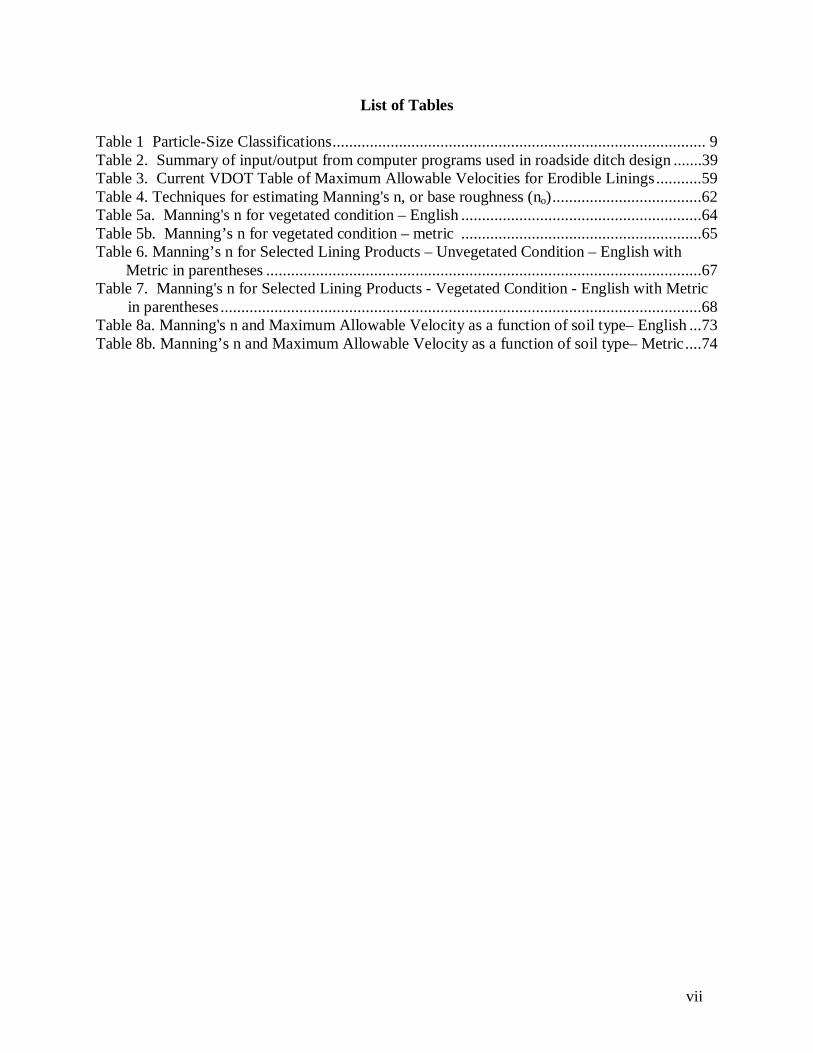
List of Tables
Table 1 Particle-Size Classifications.......................................................................................... 9Table 2. Summary of input/output from computer programs used in roadside ditch design .......39Table 3. Current VDOT Table of Maximum Allowable Velocities for Erodible Linings...........59Table 4. Techniques for estimating Manning's n, or base roughness (no)....................................62Table 5a. Manning's n for vegetated condition – English ..........................................................64Table 5b. Manning’s n for vegetated condition – metric ..........................................................65Table 6. Manning’s n for Selected Lining Products – Unvegetated Condition – English with
Metric in parentheses .........................................................................................................67Table 7. Manning's n for Selected Lining Products - Vegetated Condition - English with Metric
in parentheses....................................................................................................................68Table 8a. Manning's n and Maximum Allowable Velocity as a function of soil type– English ...73Table 8b. Manning’s n and Maximum Allowable Velocity as a function of soil type– Metric....74
viii
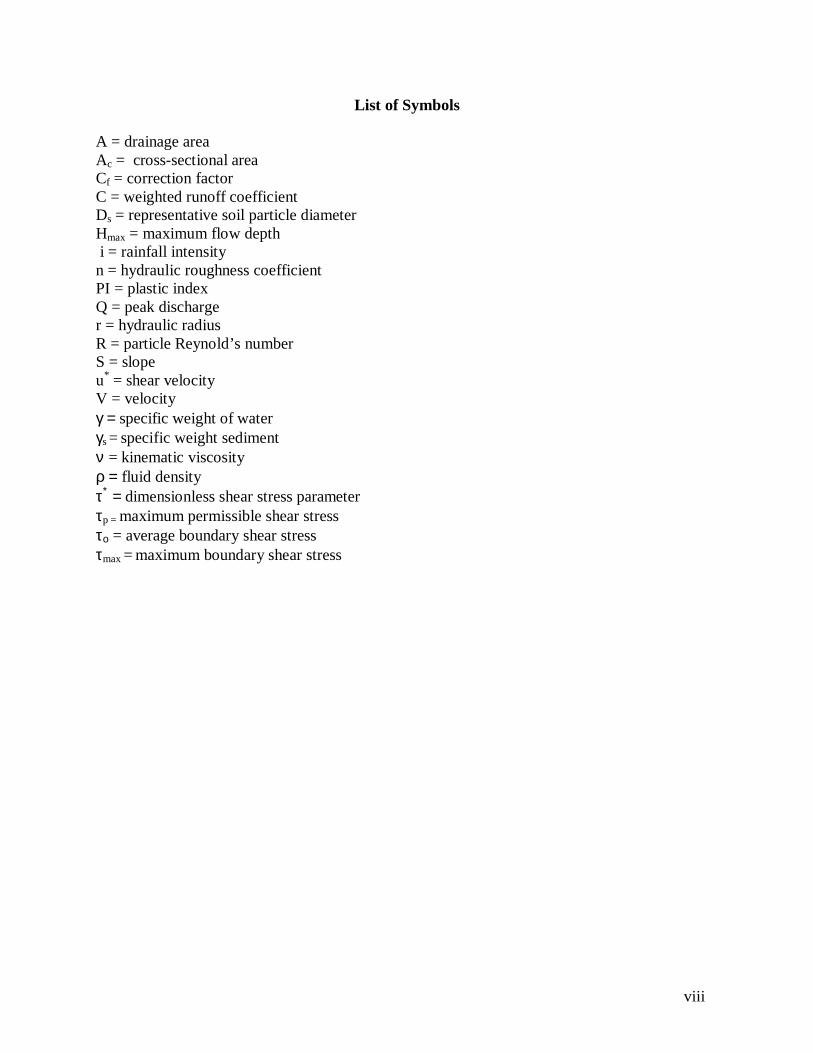
List of Symbols
A = drainage areaAc = cross-sectional areaCf = correction factorC = weighted runoff coefficientDs = representative soil particle diameterHmax = maximum flow depth i = rainfall intensityn = hydraulic roughness coefficientPI = plastic indexQ = peak discharger = hydraulic radiusR = particle Reynold’s numberS = slopeu* = shear velocityV = velocityγ = specific weight of waterγs = specific weight sedimentν = kinematic viscosityρ = fluid densityτ∗ = dimensionless shear stress parameterτp = maximum permissible shear stressτο = average boundary shear stressτmax = maximum boundary shear stress
1
INTRODUCTION
Roadside ditch erosion failures have occurred frequently enough in some regions of Virginia to
indicate that it may be desirable to revise the current design procedures. On the other side,
questions have arisen on whether roadside ditches in other locations are over-designed. The
Virginia Department of Transportation, through the Virginia Transportation Research Council,
sponsored this research in an attempt to find improved methods for designing economical ditches
and preventing erosion of soil in roadside ditches, especially during the period before an erosion-
resistant grass cover has been established in the ditch.
The objective of this research was to determine how ditch erosion problems are related to soil
type, runoff, and method of analysis and design. To accomplish this objective, an extensive
literature review was performed with the intent of identifying the current state of research and
practice for roadside ditch design. Site visits were made to each of Virginia’s nine Construction
Districts to interview personnel with regard to their design procedures, opinions, and experiences
related to ditch performance. Field visits were made, when possible, to sites of erosion failures
to make a visual assessment of factors possibly contributing to the failure and to take soil
samples for analysis. To research the current state of practice of ditch design in other states,
personal contacts were established with Department of Transportation personnel in other states
through information available on the Internet, and relevant portions of state drainage manuals
were reviewed. Available computer programs used for ditch design were collected and
evaluated. A site visit to the Mount Airy District of the North Carolina Department of
Transportation was performed with the intent of learning how NCDOT deals with problematic
soils similar in composition to those found in Virginia.
The research team from Virginia Tech who visited the District offices included Charles J. Smith,
James Coffey and Sheila Stallings. The District and Resident personnel who attended the
meetings included Drainage Engineers, River Mechanics Engineers, Environmental Engineers,
Materials Engineers, Construction Project Engineers, Transportation Engineers, Maintenance
Operations Managers and Environmental Managers, and Technicians.
2
A set of questions developed by the Geotechnical and Hydrosystems groups at Virginia Tech
was posed to the VDOT personnel at the meetings, and the VDOT personnel were invited to
offer opinions on matters not directly addressed by the questions. The intent was to learn as
much as possible about the ditch design procedures being used in the various districts, what
information is included in design, and how it is integrated into the analyses. The responses to
these questions can be found in Appendix A. One-page summaries were developed after each
visit based on the responses gathered from each VDOT District. These summaries can be found
in Appendix B.
Chapter 1 presents the results of a literature review of current publications. It highlights research
on factors influencing design, mechanisms of erosion and shear strength based on soil properties.
Chapter 2 presents the results of the review of nine states’ drainage manuals. The states included
in this review are: California, Kentucky, Maryland, New York, North Carolina, Ohio,
Pennsylvania, South Carolina, and West Virginia. This Survey of Design Guidance
characterizes the general approach to ditch design by notable design specifications. This Chapter
should serve as an overview to show general trends in current engineering practice.
Chapter 3 presents notable computer programs used for ditch design by practicing engineers in
Virginia and in the nine states surveyed for ditch design criteria. The computer programs were
obtained for evaluation and trial use. This chapter presents the programs based on the design
theory utilized by the program, and lists perceived advantages and disadvantages of each
program.
Chapter 4 concentrates on the collection and utilization of data for ditch design in Virginia. This
chapter presents factors possibly contributing to the poor performance of ditches. Focus is on
how current design and data collection practices, indicated by surveyed VDOT personnel,
deviate from established design procedures set forth in Virginia. Also, certain geographical and
management factors that impact roadway ditch performance are discussed.
3
Chapter 5 presents current research on the selection of hydraulic roughness coefficients for
various linings types and the application of stability criteria for a given soil type/lining.
Recommended tables for the selection of Manning’s n and application of Maximum Allowable
Velocity criteria are presented.
Chapter 6 discusses the overall findings of this research and draws conclusions. Final
recommendations for the improvement of roadside ditch design in Virginia are made and
suggestions for future research are presented in Chapter 7.
Chapter 8 gives a detailed description of the proper design procedure with the recommended
tools is presented.
4
CHAPTER 1. REVIEW OF LITERATURE
The primary purpose of roadside ditches is to serve as conveyance structures preventing water
from pooling on the roadway surface. Effective roadway ditches prevent overland runoff from
reaching the roadway, as well as drain water from the road surface. Economical ditches should
convey the intended design storm efficiently and require minimum maintenance while serving
their intended purpose of roadway drainage structures.
1. Factors Influencing DesignThe primary factor influencing the design of roadside drainage ditches is driver safety. Driver
safety precautions influence various parameters of ditch design including ditch shape, slope,
lining considerations, and capacity requirements.
1.1.1 Ditch Shape
Channel shapes are generally determined for a location by considering the terrain, flow regime
and the quantity of flow to be conveyed (AASHTO 1992). Typically, ditch geometry is either V-
shaped or trapezoidal. Roadway channels should provide recoverable slopes, thereby
minimizing the impact of errant vehicles. This can be accomplished by designing ditch cross
sections with mild side slopes. Depending on side slopes used, both V-shaped and trapezoidal
ditches can provide driver safety and be economical to construct. When mild side slopes are
used, the shape tends to approach a parabolic shape, which is recognized as being the most
hydraulically efficient shape (AASHTO 1992). Because V-shaped ditches are more susceptible
to erosion (AASHTO 1992), trapezoidal ditches may be preferred on certain soil conditions, such
as fill sections and highly erodible soils.
The side slopes of the ditch/channel should not exceed the angle of repose of the soil comprising
the ditch line, and should generally be 3:1 or flatter (Brown et al, 1996, AASHTO 1991). Where
local conditions dictate the use of some type of rigid lining, the use of steeper slopes (>2:1) may
be more economical (AASHTO 1992).
1.1.2 Ditch SlopeChannel slope is one of the major parameters in determining shear stress exerted by the flow on
the boundary. Particle entrainment will occur when the shear stress exerted on the boundary by
5
the flow exceeds the resisting shear stress exerted by the boundary. Because particle entrainment
is to be minimized, flow in roadside ditches is usually designed to be subcritical. When channel
gradients are in excess of about 2 %, flow could be in supercritical state (Chen and Cotton 1988).
Special design features, such as drop structures, check dams, etc., should be considered to
minimize shear stresses exerted on the ditch boundary/lining, and avoid the occurrence of
supercritical flow.
Caution should be exercised when designing ditch gradients in excess of roadway gradients.
When this practice is necessary, for example when draining the ditch to a natural stream, proper
safety measures should be installed to insure driver safety along the design reach.
1.1.3 Lining Considerations
During the construction phase, when the bare ditch line is fully exposed to weathering processes,
the chance for significant erosion is the highest. During heavy storms, it is estimated that as
much as 100 tons/acre of bare soil can be splashed into the air by the impact of raindrops alone
(Gray and Sotir, 1996). Impact from raindrops on bare earth has been estimated to displace
splashed particles more than 2 feet vertically and 5 feet laterally on level ground (Gray and Sotir,
1996). Consequently, a net lateral movement down to the flow line would be expected on
embankments, such as ditch side walls. When loosely compacted particles, such as particles
displaced by raindrops, enter the flow line, they can become easily entrained during storm
events. Once entrained by the flow, sediment will be carried downstream, eventually being
deposited within the ditch or in a receiving stream. The receiving stream water quality may
become impaired, depending on the significance of the erosion/deposition event, and
consequently the stream ecosystem may be adversely affected. It is estimated that 70 % of the
soil entering the streams and rivers from natural geologic erosion, agricultural lands, forest and
range land, and construction sites could be controlled by the use of existing erosion control
methods (Marek, 1993).
Because erosion can become a significant consequence from roadway ditch construction,
protective linings, either temporary and/or permanent, should be applied when necessary.
Temporary linings are expected to provide erosion protection through the establishment of
vegetation and then degrade over time, typically a 2-year period. When the predicted velocity of
6
a ditch exceeds the stability criteria for the soil comprising the ditch lining, temporary linings are
used.
Synthetic linings (like jut matting), straw, and wood chips are examples of some temporary
linings. Straw covering alone provides an excellent mulch material and has the advantage of
being widely available (Washington State Department of Transportation, 1990). Straw can
effectively absorb raindrop impact, moderate soil temperature, and conserve moisture, while
enhancing water infiltration and vegetation establishment (Washington State Department of
Transportation, 1990). When relatively brief (<3 months) protection is needed, straw can be an
inexpensive way to reduce erosion and promote vegetation growth (Washington State
Department of Transportation, 1990). Jute matting is a temporary matting, decomposing in 2
years or less, which is designed to promote vegetation growth while providing erosion control.
Because jute matting may be expensive, it is most applicable to smaller sites. Though jute
matting is not well suited for rocky soils, on other soil types it can be applied over straw to
increase effectiveness (Washington State Department of Transportation, 1990). Another type of
temporary lining with relatively high effectiveness is a woven straw blanket, made of 100%
wheat straw with netting. Proper installation techniques can ensure high effectiveness, but high
cost of the material make it best suited for locations in need of immediate erosion protection.
The Virginia Department of Transportation classifies temporary erosion control mattings by
performance parameters. The Erosion Control (EC) classes used in Virginia are EC-2, EC-3a
and EC-3b, with EC-3b offering the highest resistance to erosion. Synthetic linings from many
manufacturers are approved in each class of lining for use on Virginia highways. When flow
conditions exceed the stability of these lining, permanent linings will be specified.
Permanent linings can be either flexible or rigid. Typically rigid linings include concrete, paved
or other low permeability, linings. Because these types of linings tend to have low permeability,
concrete and pavement linings may inhibit infiltration where infiltration may be desirable. High
velocities are generated, which may cause erosion problems at ditch outlets. In addition, rigid
linings have been associated with water seeping beneath the structure, at the sidewalls and
structure inlet, causing soil piping under the structure and consequent failure.
7
When rigid linings fail, the failure is usually abrupt with little fore-warning, and, consequent
repairs are expensive. From meetings with Virginia Department of Transportation (VDOT)
hydraulic designers and discussions with other states’ hydraulic engineers, it was learned that
concrete and pavement linings are used less frequently in modern ditch design because of high
failure rates associated with piping under the structure. Instead, riprap is being used more
frequently as a rigid lining. Riprap provides a less rigid boundary and the ability to mold with
changing conditions in the ditch line while providing continued erosion protection. When used
with a geofabric underlying the rock, fine particle entrainment can be minimized.
When stability criteria permit, flexible permanent linings, typically grass, are preferred over rigid
linings. Flexible linings are generally less costly to construct and have reduced maintenance
costs. In addition, flexible linings, such as grass, offer high hydraulic resistance, which promotes
lower velocities and increased infiltration. While the grass blades serve to reduce flow velocity
and thereby lowering shear stress, the root structure reinforces the shear resistance of the soil.
As a natural permanent lining, vegetated linings have the ability re-establish themselves
seasonally, provided proper environmental conditions. Typically, states have a variety of seed
mixes to accommodate seasonal and geographical changes across their state. Generally, a period
of about 2-years is observed to ensure full establishment of a vegetated lining. When immediate
protection is necessary, sod can be used though it is much more expensive.
Geotextile materials can also be used for permanent soil stabilization on ditch linings and side
slopes. These are not biodegradable and serve as permanent soil reinforcement, while providing
for the establishment of vegetation.
1.2 Mechanisms of ErosionA majority of published literature concentrates on mechanisms of erosion in rivers and small
natural streams. Little research has been directed at mechanisms of erosion and erosion control
of roadway ditches. Though these manmade ditches are inherently different from natural
channels and often much smaller, erosion mechanisms from natural streams/rivers are applicable
to roadway ditches. While natural streams tend to be larger than roadway ditches, the
mechanisms of flow conveyance and erosion are similar. A large number of variables are
8
involved in the erosion process. It may be difficult to determine which variable is the dominate
erosion mechanism in the field.
When a stream is in equilibrium with its environment, its slope will be an independent variable.
That is, the stream has adjusted so that the flow is capable of transporting only the amount of
sediment supplied at the upper end of the stream and by the tributaries (Richardson et all, 1990).
When a change occurs upstream, the stream will respond by a change in slope to accommodate
the change by increasing or decreasing the slope downstream. An increase/decrease in channel
slope corresponds to erosion /deposition of soil comprising the ditch line.
1.2.1 Passive Mechanisms Affecting Erosive Capability of Active MechanismsVarious soil properties, including granulation, particle shape, density, permeability, and layering,
influence the ability of particles to become entrained by the flow. Depending on the
predominant size of particles present, soils are classified as gravels, sands, silts and clays.
Gravels and sands are non-cohesive, coarse soils while silts and clays consists of finer grained
particles characterized by cohesive properties. Many organizations have developed systems of
classifying soils by particle size. Table 1 presents various classifications of soil by particle size.
Particle entrainment of non-cohesive soils is more easily understood than cohesive soils
primarily because inter-particle attraction is not involved. Noncohesive soil becomes entrained
particle by particle. The rate of particle removal can be influenced by particle shape, orientation
to flow, density, and tractive force exerted by the flow on the soil boundary. Flow direction and
velocity can also influence the erosion rate of the bank (Richardson et al, 1990).
Shields’ published a criterion for the initiation of movement of uniform granular material on a
flat bed. A Shields parameter (τ*) is related to particle Reynold’s number to determine if flow
conditions support particle entrainment for a given characteristic particle size.
9
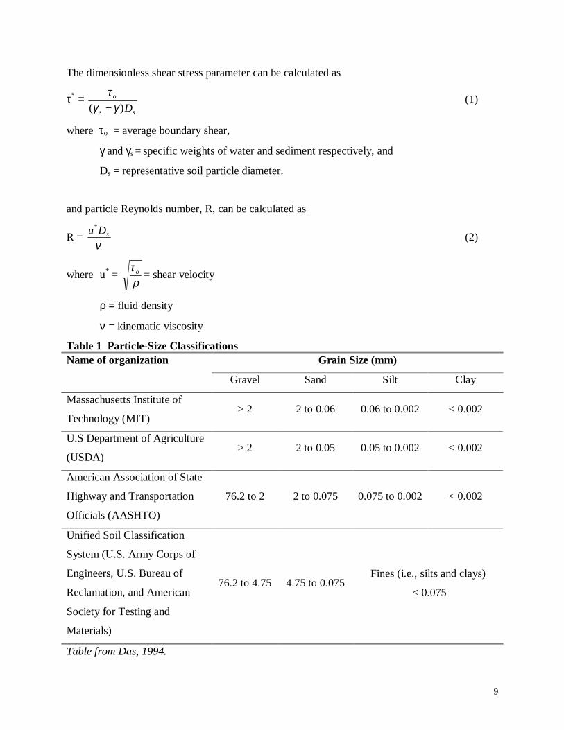
The dimensionless shear stress parameter can be calculated as
τ∗ = ss
o
D)( γγτ−
(1)
where τo = average boundary shear,
γ and γs = specific weights of water and sediment respectively, and
Ds = representative soil particle diameter.
and particle Reynolds number, R, can be calculated as
R = ν
sDu*
(2)
where u* = ρτ o = shear velocity
ρ = fluid density
ν = kinematic viscosity
Table 1 Particle-Size ClassificationsGrain Size (mm)Name of organization
Gravel Sand Silt Clay
Massachusetts Institute of
Technology (MIT)> 2 2 to 0.06 0.06 to 0.002 < 0.002
U.S Department of Agriculture
(USDA)> 2 2 to 0.05 0.05 to 0.002 < 0.002
American Association of State
Highway and Transportation
Officials (AASHTO)
76.2 to 2 2 to 0.075 0.075 to 0.002 < 0.002
Unified Soil Classification
System (U.S. Army Corps of
Engineers, U.S. Bureau of
Reclamation, and American
Society for Testing and
Materials)
76.2 to 4.75 4.75 to 0.075Fines (i.e., silts and clays)
< 0.075
Table from Das, 1994.
10
The initiation of motion and the transport of non-cohesive sediments are both influenced by the
submerged weight of the particles. A critical Shields’ parameter, τc*, indicates a flow condition
corresponding to the threshold of sediment movement. The Shield’s stress (τ*) becomes
independent of Reynold’s number for fully rough flow. A Reynold’s number greater than 500 is
characteristic of fully rough flow (Vanoni, 1977).
Unlike non-cohesive soils, the rate of erosion of cohesive soils is not as easily understood
because of inter-particle attractions. Because cohesive soils have particle interactions, they tend
to be more resistant to erosion. Relatively large forces are necessary to break the aggregates
within the bed and relatively small forces are necessary to transport the material (Hoffman and
Verheij, 1997).
In the article by Hoffman and Verheigh (1997), discussion is made on experiments performed by
Mirtskhoulava (1998, 1991) that have shown that the scour of clay soils with natural structure in
a water saturated state occurs in several stages. The first stage is characterized by roughening of
the surface when loosened particles and aggregates separate and those with weakened bonds, are
washed away. With a rougher surface, a higher drag (shear force) is produced and the bonds
between the remaining protruding aggregates are gradually destroyed until the aggregate is
entrained by the flow. It is said that the scour process is influenced by cohesion, Cation
Exchange Capacity (CEC), salinity, Sodium Adsorption Ratio (SAR), pH of pore water,
temperature, sand, organic content, and porosity. Hoffman and Verheigh (1997) report that
Mirtskhoulava (1988, 1991) concluded that cohesion at saturation water content and the size of
the particle diameter appear to be the most significant features in determining the stability of
cohesive sediments. A general trend reported in this article is that increasing organic content
will cause an increase in the cohesiveness of the sediments resulting in a smaller erosion rate.
This trend is reportedly known qualitatively and not quantitatively. Because cohesion is a
significant force, cohesive soils are more likely to fail due to mass wasting processes such as
sliding when undercut and/or saturated (Richardson et al, 1990). From field observations, it is
known that the resistance to erosion of artificial channels may increase considerably with time
(Chapuis, 1985).
11
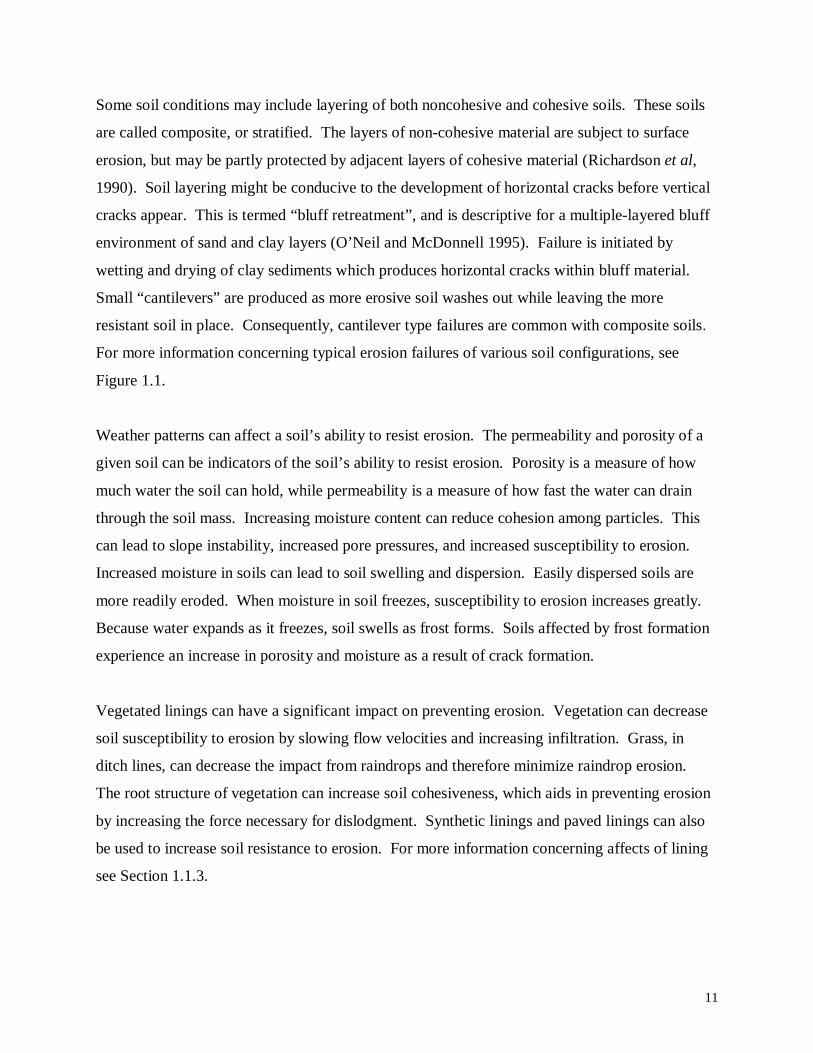
Some soil conditions may include layering of both noncohesive and cohesive soils. These soils
are called composite, or stratified. The layers of non-cohesive material are subject to surface
erosion, but may be partly protected by adjacent layers of cohesive material (Richardson et al,
1990). Soil layering might be conducive to the development of horizontal cracks before vertical
cracks appear. This is termed “bluff retreatment”, and is descriptive for a multiple-layered bluff
environment of sand and clay layers (O’Neil and McDonnell 1995). Failure is initiated by
wetting and drying of clay sediments which produces horizontal cracks within bluff material.
Small “cantilevers” are produced as more erosive soil washes out while leaving the more
resistant soil in place. Consequently, cantilever type failures are common with composite soils.
For more information concerning typical erosion failures of various soil configurations, see
Figure 1.1.
Weather patterns can affect a soil’s ability to resist erosion. The permeability and porosity of a
given soil can be indicators of the soil’s ability to resist erosion. Porosity is a measure of how
much water the soil can hold, while permeability is a measure of how fast the water can drain
through the soil mass. Increasing moisture content can reduce cohesion among particles. This
can lead to slope instability, increased pore pressures, and increased susceptibility to erosion.
Increased moisture in soils can lead to soil swelling and dispersion. Easily dispersed soils are
more readily eroded. When moisture in soil freezes, susceptibility to erosion increases greatly.
Because water expands as it freezes, soil swells as frost forms. Soils affected by frost formation
experience an increase in porosity and moisture as a result of crack formation.
Vegetated linings can have a significant impact on preventing erosion. Vegetation can decrease
soil susceptibility to erosion by slowing flow velocities and increasing infiltration. Grass, in
ditch lines, can decrease the impact from raindrops and therefore minimize raindrop erosion.
The root structure of vegetation can increase soil cohesiveness, which aids in preventing erosion
by increasing the force necessary for dislodgment. Synthetic linings and paved linings can also
be used to increase soil resistance to erosion. For more information concerning affects of lining
see Section 1.1.3.
12
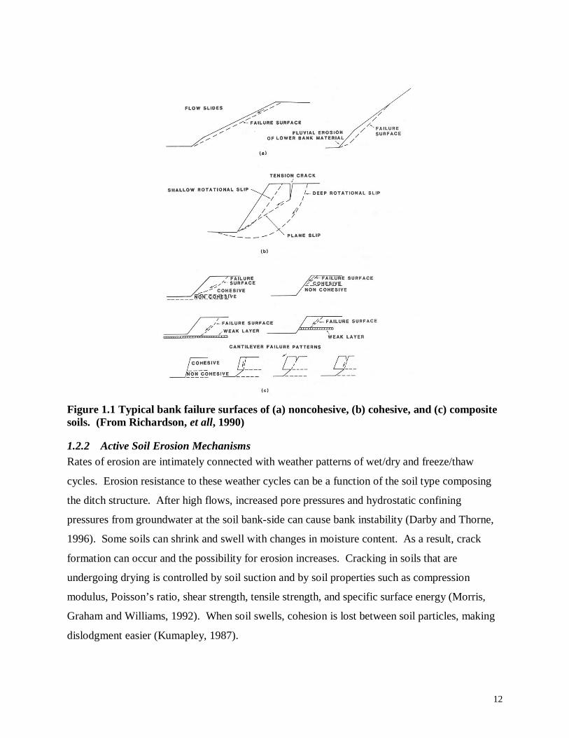
Figure 1.1 Typical bank failure surfaces of (a) noncohesive, (b) cohesive, and (c) compositesoils. (From Richardson, et all, 1990)
1.2.2 Active Soil Erosion MechanismsRates of erosion are intimately connected with weather patterns of wet/dry and freeze/thaw
cycles. Erosion resistance to these weather cycles can be a function of the soil type composing
the ditch structure. After high flows, increased pore pressures and hydrostatic confining
pressures from groundwater at the soil bank-side can cause bank instability (Darby and Thorne,
1996). Some soils can shrink and swell with changes in moisture content. As a result, crack
formation can occur and the possibility for erosion increases. Cracking in soils that are
undergoing drying is controlled by soil suction and by soil properties such as compression
modulus, Poisson’s ratio, shear strength, tensile strength, and specific surface energy (Morris,
Graham and Williams, 1992). When soil swells, cohesion is lost between soil particles, making
dislodgment easier (Kumapley, 1987).

13
Temperature exposure can influence erosion susceptibility by inhibiting vegetation growth
through heat and causing freezing when cold. Wind abrasion can erode banks and loosen
particles. The low permeability characteristic of clays and silts reduces the effects of piping and
frost heaving (Richardson et al, 1990). The volume of soil can expand about 10% due just to
water expanding in the soil pores (Holtz and Kovacs, 1981). This leads to crack formation upon
differential expansion, and consequently increased erosion probability. Needle ice can occur
even with mild freezing temperatures when sufficient soil bank moisture is present (Lawler,
1993). Significant bank sediment mobilization due to needle ice was reported, representing
32%-43% of total bank erosion, in experiments performed by Lawler (1993).
1.3 Shear Strength Based on Soil PropertiesShear strength under applied loads is a function of various soil parameters, including soil type,
moisture content, soil density, and energy applied for compaction. The triaxial test is usually
used to develop total stress failure envelopes using Mohr circles. In an article by Ohu et al
(1986), results of experiments, measuring shear strength on three soil textures with varying
organic matter and subjected to three levels of compaction effort, are discussed. From their
experiments, Ohu, et al (1986) were able to conclude that soil compaction increased the shear
strength of the soils regardless of moisture content. Also, it was found that increased organic
matter decreased the shear strength despite moisture content for all the compaction effort
applied.
The results of this study were applied to agricultural soils that are subjected to many passes of
different farm machines, which cause increased soil compaction that can inhibit crop growth.
Increasing the organic content of these soils can counter-act effects of compaction imparted by
farm machinery. Similarly, roadside ditches are subjected increased compaction imparted by
construction machinery during road construction, and then by mowing equipment during ditch
maintenance. Increasing organic matter in roadside ditches could decrease the shear strength of
soils, allowing the vegetation root structure to penetrate soils more easily.
14
1.4 DiscussionThe information presented in this section reveal factors influencing the design and/or the
performance of roadside ditches. The primary factor influencing the design of roadside drainage
ditches is driver safety. Driver safety precautions influence various parameters of ditch design
including ditch shape, slope, lining considerations, and capacity requirements. Understanding
how these parameters can influence the performance of ditches can lead to the more economical
ditch design. The performance of roadside ditches is dependent on the ability of the designer to
accurately determine stability of ditches based on design criteria and the level of understanding
the designer has of erosion mechanisms.
The information presented in this section was used as a basis to assess sites of erosion failures at
each of Virginia’s nine construction districts. Visual observations were taken at each site.
Special notes were taken indicating the occurrence of steep slopes, occurrence of lining stability
failures, influence of ditch shape, and any environmental factors which may have contributed to
the failure of the ditch. Soil samples were collected at each site visited. The samples were tested
in the lab with the intent of determining which parameters, if any, contributed to the failure of
the site.
15
CHAPTER 2. SURVEY OF DESIGN GUIDANCE
2.1 BackgroundThe primary goal of this section is to determine the current state of practice for roadside ditch
design. Presently, no comprehensive study of roadside ditch design practices has been found in
published literature. This section will discuss the findings of a literature review focussing on
current practice as defined by state drainage manuals, federal highway publications, and in other
scientific publications. The results of this survey should serve as a general template to view
notable similarities and differences among ditch design practices in various states.
Roadside ditch design is an important aspect of roadway structure and safety. Their design may
be influenced by many factors, including motorists’ safety, aesthetics, economy of construction
and maintenance. A stable ditch should provide adequate capacity for the intended design storm
and be resistant to erosion failures. Ideally, the ditch design should also provide recoverable
slopes to enhance driver safety in errant vehicles. Inadequate design of ditch capacity can result
in compromised driver safety conditions, including water overtopping the ditch line and flooding
the intended path of travel. Also, erosion failures can result in steeper ditch sideslopes, and
possibly failure of the roadway shoulder and structure. Adequate right-of-way should be
acquired to accommodate the required ditch sideslopes and capacity.
The successful design of roadside ditches must satisfy two requirements: ditch capacity and
stability. In general, the 10-year storm is used to determine ditch capacity, while the 2-year
storm is used to check ditch stability. The logic implied in the selection of storm return period is
that the initial period after ditch construction, before vegetation is developed, constitutes the
most critical period regarding ditch stability. After vegetation is fully developed, the channel is
considered stable and channel capacity becomes more critical. Highly traveled roads, such as
interstates, may require an increase of the design storm to reduce the probability of capacity
failure.
16
Flow depth and velocity are calculated following the basic principles of open channel flow.
Manning’s formula, shown below, is used to relate flow velocity to ditch slope, hydraulic radius,
and a hydraulic roughness coefficient.
n
1V = r 2/3 S 1/2 for metric units, and
nV
49.1= r 2/3 S ½ for English units (3)
where: V = velocity, m/s (ft/s)
n = hydraulic roughness coefficient
r = hydraulic radius, m (ft)
S = slope, m/m (ft/ft)
Appropriate selections of Manning’s roughness coefficient should be made to reflect the lining
condition of the ditch under consideration. For instance, ditch capacity should be checked using
the hydraulic roughness coefficient reflecting a fully vegetated ditch lining.
The Continuity Equation is used to relate discharge, Q, to flow velocity and cross-sectional area,shown below
Q = V Ac
where: Ac = cross-sectional area (4)
Ditch peak flow, based on a selected storm return period, is generally calculated using the
Rational Method.
Q = Cf C i A (5)
where: Q = peak discharge (cfs or m3/s)
Cf = correction factor
C = weighted runoff coefficient
i = rainfall intensity (in/hr or mm/hr)
A = drainage area (ac or ha)
17
When English units are used, the conversion factor Cf = 1.008 to convert ac-in./hr to cfs, and is
routinely ignored because of its insignificant affect on the calculated peak flow. For metric units
Cf = 0.00278 is used to convert ha-mm/hr to m3/s (Bedient and Huber, 1992). When applied
correctly, the Rational Method provides a quick and easy method of approximating peak flow for
small watersheds, like those typically associated with ditches.
The intricate relationship between capacity and stability must be satisfied to maintain an
adequate, stable ditch. Designing ditches resistant to particle entrainment requires a good
understanding of soil properties and flow behavior. When material forming the ditch boundary
effectively resists erosion, stability is achieved. Ditch stability is a function of several aspects
unique to each location, including soil type and plasticity, particle size and shape, etc. Presently,
two theories are in practice for the design of stable, erosion resistant ditches: the Maximum
Allowable Velocity Method and the Tractive Force Method.
2.1.1 Maximum Allowable Velocity Method
The traditional approach to ditch stability design, and the current VDOT practice, is to use a
maximum allowable velocity criterion. This is an empirical approach that assigns a maximum
allowable velocity to various soil types. The relationship between maximum velocity and soil
type has been developed through lab experiments and from field experience.
To implement this method, the designer will initially need to determine the 10-year and 2-year
storm flows. Adequate ditch dimensions are determined using the 10-year storm flow and a fully
developed vegetation condition. Ditch stability is checked based on the 2-year storm flow under
bare earth conditions. Using the soil type comprising the bare ditch line, the designer determines
the corresponding maximum allowable velocity from a chart and compares it to the predicted 2-
year storm velocity. If the predicted 2-yr storm velocity exceeds the allowable velocity for the
given soil type, the ditch will be expected to have erosion failure. Consequently, the designer
must make revisions in the ditch design, possibly reconsidering selection of ditch geometry,
slope, or lining, until a stable configuration is found.
18
Computer programs have been developed which evaluate ditch design using the Maximum
Allowable Velocity Method. The Virginia Department of Transportation has developed
RDITCH, a DOS based program, which facilitates the design of roadside ditches. This program
contains a computational routine which calculates peak flow using the Rational Method. When
provided with the required hydrological data and ditch geometry, the program will calculate flow
depth and velocity for both the 2-year and 10-year storms. From the output data, the user must
determine if the ditch configuration is adequate, and then if the configuration is stable based on a
selected ditch lining.
Anderson & Associates, a Civil Engineering consulting firm based in Blacksburg, VA, has
developed an Excel spreadsheet which performs calculations for ditch design in accordance with
the Virginia Drainage Manual. The spreadsheet is programmed to evaluate capacity and stability
of a given ditch configuration. User inputs of hydrological data allow the spreadsheet to
calculate peak storm flow using the Rational Method. With a given ditch configuration, capacity
is checked using the 10-year storm and fully developed vegetation roughness. The predicted 2-
year storm velocity is compared against a maximum allowable velocity for bare earth. If the
stability requirement is satisfied, the program stops. If stability is not met, the program will
automatically iterate lining selection until a stable configuration is met. Upon program
completion, a message is displayed indicating the stable ditch lining.
More information concerning these programs is provided in Chapter 3.
2.1.2 Tractive Force Method
The Tractive Force Method is a more recently developed design theory. The Federal Highway
publication HEC-15 (1988) discusses the application of the Tractive Force design theory to
roadside ditch design.
Water flowing over a boundary creates a shear stress. The boundary (bare soil, synthetic, or
vegetated) can withstand a certain maximum permissible tractive force before erosion occurs.
Based on the Tractive Force theory, for a ditch to remain stable, the shear stress applied by
flowing water should not exceed the permissible stress of the boundary soil or lining.
19
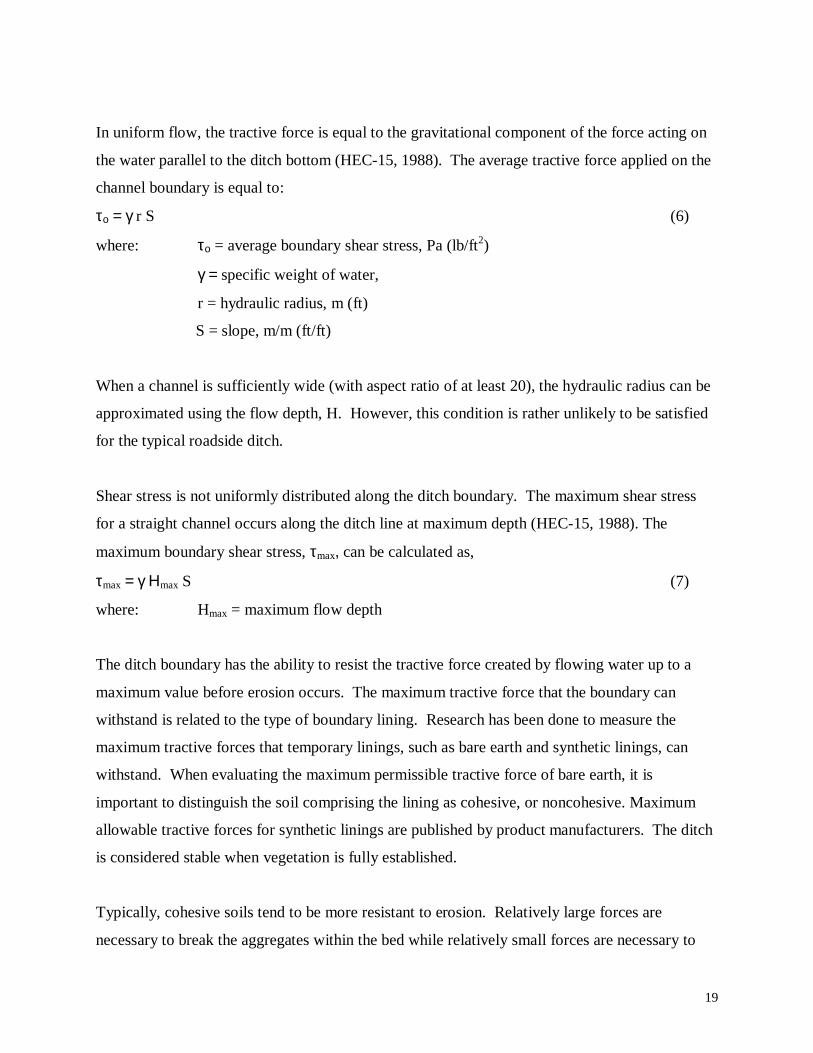
In uniform flow, the tractive force is equal to the gravitational component of the force acting on
the water parallel to the ditch bottom (HEC-15, 1988). The average tractive force applied on the
channel boundary is equal to:
το = γ r S (6)
where: το = average boundary shear stress, Pa (lb/ft2)
γ = specific weight of water,
r = hydraulic radius, m (ft)
S = slope, m/m (ft/ft)
When a channel is sufficiently wide (with aspect ratio of at least 20), the hydraulic radius can be
approximated using the flow depth, H. However, this condition is rather unlikely to be satisfied
for the typical roadside ditch.
Shear stress is not uniformly distributed along the ditch boundary. The maximum shear stress
for a straight channel occurs along the ditch line at maximum depth (HEC-15, 1988). The
maximum boundary shear stress, τmax, can be calculated as,
τmax = γ Ηmax S (7)
where: Hmax = maximum flow depth
The ditch boundary has the ability to resist the tractive force created by flowing water up to a
maximum value before erosion occurs. The maximum tractive force that the boundary can
withstand is related to the type of boundary lining. Research has been done to measure the
maximum tractive forces that temporary linings, such as bare earth and synthetic linings, can
withstand. When evaluating the maximum permissible tractive force of bare earth, it is
important to distinguish the soil comprising the lining as cohesive, or noncohesive. Maximum
allowable tractive forces for synthetic linings are published by product manufacturers. The ditch
is considered stable when vegetation is fully established.
Typically, cohesive soils tend to be more resistant to erosion. Relatively large forces are
necessary to break the aggregates within the bed while relatively small forces are necessary to
20
transport the material (Hoffman and Verheij, 1997). However, quantifying the amount of
influence the cohesive property has on erosion resistance of bare soil is difficult because of
limited research in this area. The publication HEC-15 has related the permissible tractive force
for cohesive soils as a function of soil plasticity index and compactive effort.
Extensive research has been done on particle entrainment of noncohesive soils. Shields’
published a criterion for the initiation of movement of uniform granular material on a flat bed
(Vanoni, 1977). This classic work relates the Shields’ parameter, τ*, and particle Reynold’s
number, R, to determine if flow conditions support particle entrainment (see equations 1 and 2).
When particle motion is incipient, the Shields' parameter is said to be critical, τc*. The
dimensionless critical shear stress becomes independent of Reynold’s number when Reynold’s
number exceeds 500. The flow in this Reynold’s range is said to be fully rough. Extensive
research has shown that critical Shields’ parameter is in the range of 0.033 to 0.06 for fully rough
flow (Vanoni, 1977). Typically, this region describes a coarser boundary, beginning in the range
of fine gravel.
Currently, two programs have been developed by the Federal Highway Administration that
facilitate the design of roadside channels using the Tractive Force Theory as presented in HEC-
15 (1988). The program Stable Channel Linings (FHWA HY-15) checks the stability of simple,
straight ditches with lining, excluding the bare earth condition. A more complex model,
HYDRAIN, is an integrated drainage design computer system. Within HYDRAIN, the submenu
HYCHL is intended for use in the design of roadside channels using the tractive force theory
presented in HEC-15. This program has the capability of determining stability of ditches with
rigid, vegetative, gabion, and temporary linings including the bare earth condition for both the
cohesive and noncohesive soil conditions. Stability analysis can include side shear and ditches
designed with bends.
More information concerning these programs is provided in Chapter 3.
2.2 MethodsTo determine current design practices for roadside ditches, various state drainage manuals were
reviewed. Some criteria used in selecting states for the survey include geomorphological
21
features similar to those found in Virginia, and densely populated states. Information from nine
states’ Drainage Manuals and telephone interviews with hydraulic engineers was collected and
evaluated. The states included in this review are: California, Kentucky, Maryland, New York,
North Carolina, Ohio, Pennsylvania, South Carolina, and West Virginia.
Contacts from each state were established by use of available information on the web. Because
of the diversity in responses concerning methods of roadside ditch design received when
interviewing Virginia engineers, it should be noted that, at most, two engineers from each state
were interviewed concerning their respective state’s ditch design practice. Therefore,
information obtained from telephone interviews may not reflect design practices across the entire
state. However, relevant portions of Drainage Manuals were obtained and should provide a
template that accurately describes the general approach to roadside ditch design practice in each
state surveyed.
Other publications, such as those published by the Federal Highway Administration (FHWA)
and journal articles, have been consulted and included in this review.
2.3 ResultsThe Federal Highway Administration (FHWA) has made a considerable effort to improve the
methods used for the design of roadside ditches. In 1988, the publication HEC-15 (1988),
intended for the design of roadside channels with flexible linings, was released. This publication
promotes the use of the tractive force method for roadside channels. Information necessary for
the complete design of roadside channels is available in HEC-15 through charts and graphs.
Drainage manuals from various states surveyed were reviewed and summarized below by
notable design specifications. These specifications have been generalized and listed below as
topics. Because each state uniquely specifies design criteria, not all states will be listed under
each topic. The topic areas should serve as an overview to show general trends in engineering
practice.
22
Design Method for Channel Stability
Tractive Force Method• Kentucky – The tractive force theory is prescribed with a descriptive design procedure
following FHWA HEC-15.
• Pennsylvania – FHWA HEC-15 procedures should be used to design stable ditches and
to select appropriate erosion control measures.
• South Carolina – FHWA HEC-15 procedures should be used to design a stable channel.
The HYCHL routine in HYDRAIN is suggested to aid design. These methods are not
recommended when the discharge under consideration exceeds 1.4 m3/s (49.4 ft3/s).
When flow exceeds 1.4 m3/s (49.4 ft3/s), then riprap lining is to be used following FHWA
HEC-11 (1987). HEC-11 should be used for the design of some types of lining.
Maximum Velocity Approach
• California
• Maryland
• North Carolina
• Ohio
• Virginia
Either Design Theory Recognized
• New York – The designer can choose which design theory to use. When following the
maximum permissible velocity approach, the designer is referred to Hydraulic Design
Series No. 3 (FHWA, 1961), Hydraulic Design Series No. 4 (FHWA, 1965), and New
York Geotechnical Design Procedures No. 10 (NYDOT, 1995). When following the
permissible tractive force approach, the designer is referred to the FHWA publication
HEC-15 and the HYDRAIN modeling program.

23
• West Virginia – The published Drainage Manual, last updated 1984, indicates that a
maximum velocity approach should be used. However, HYDRAIN is the computer
program recommended and given to consultants for design by the state, which employs
the tractive force design approach.
Specified Freeboard Requirements
• Maryland – A freeboard of 9 inches measured below the edge of the shoulder is specified.
• Ohio – A freeboard of 12 inches should be observed.
• Pennsylvania – Freeboard should be either 2 feet or 6 inches below the sub-base, whichever
governs.
• Virginia – A freeboard of 12 inches should be observed.
• West Virginia – A freeboard of 18 inches below the edge of the shoulder is specified. Flow
depth should not exceed one foot in ditches for all roads. An exception to this rule can be
applied to low volume roads where economic design warrants deviation from this standard.
Minimum Ditch Grades
• California – The lowest recommended grade for ditch design should be 0.25% for earth
ditches and 0.12% for paved ditches.
• Kentucky – A minimum grade of 0.5% should be observed to minimize ponding and
sediment accumulation.
• New York – The minimum slope for turf lined roadside channels should be 0.5% to prevent
sediment deposition. The grade of channels fully lined with grass should not be less that
0.5%.
• Ohio – As a general rule, the desirable minimum ditch grade should be 0.48% with an
absolute minimum of 0.24%.
• South Carolina – Minimum grade on ditches should be 0.3% where possible.
Determining Ditch Capacity and Protective Lining
• Maryland – Capacity and lining requirements should accommodate a 10-year frequency
storm.
24
• Ohio – For roadways with design traffic of 2000 ADT or less, it is recommended that a 5-yr
frequency storm be used to determine the flow depth. For roadways with design traffic
exceeding 2000 ADT, it is recommended that a 10-year frequency storm be used to
determine the flow depth, and a 5-year frequency flow depth and velocity be used to
determine erosion control linings, where needed.
• Pennsylvania – In general, a 10-year storm frequency should be used for design of ditches.
• South Carolina – The design storm for roadside ditches is the 10-year storm for drainage
areas from 0-40 acres, the 25-year storm for drainage areas from 40-500 acres and the 50-
year storm for drainage areas greater than 500 acres.
• Virginia – The 2-year storm is used to determine lining requirements, and the 10-year storm
is used to determine capacity requirements.
• West Virginia – Capacity should be determined based on a 10-year storm frequency. If grass
is adequate as a ditch lining, the earth ditch as originally constructed is checked to see if
matting is required for a 2-year frequency during the establishment of vegetation.
Ditch Geometry Specifications
• Maryland – Flat bottom (trapezoidal) ditches are used in fill sections.
• New York – Roadway ditches should be trapezoidal or V-shaped. Toe-of-slope ditches
should be trapezoidal. Intercepting ditches should be semi-circular or trapezoidal.
• Ohio – Special ditches, such as toe of fill ditches and steep ditches used to carry flow from a
cut section to valley floor, are usually trapezoidal in shape
Specifications for Protective Linings, Including Concrete
• Kentucky – Due to the high failure rate of paved lining channels, paved linings will be used
only in extreme cases under the approval of the Division of Design.
• Maryland – Soil stabilization matting is to be used for all ditches with flow velocity less than
5.0 ft/s. Ditches with flow velocities exceeding 5 ft/s should be designed with riprap.
• New York – Roadway channels should be lined to minimize or prevent erosion. Turf, and
then stone filling, are preferred, in order of preference, when linings need to be applied for
stability. An apron of stone filling will be specified at the end of a paved channel to
25
minimize erosion. A 0.5-meter wide strip of sod is to be specified on each side adjacent to
the paved lining.
• South Carolina – Preferred channel lining materials in order of preference for the hydraulic
design stand point are: 1) Grass lining, 2) Temporary biodegradable lining with grass, 3)
Permanent synthetic lining with grass riprap, 4) Wire enclosed rock, called gabions, and
mattresses, 5) Asphalt paving, 6) Articulated precast blocks. Resident Maintenance
Engineers usually prefer asphalt paving to riprap because of problems encountered when
mowing. The designer should work with them to arrive at an acceptable design. The use of
silt fences is limited to areas of sheet flow and areas of concentrated flow of less than 1.0 cfs.
The sheet flow should have no more than ¼ cfs per 100 feet of silt fence and the maximum
fill slope protected by the fence must not exceed 2:1.
Minimum Velocity Specification
• Maryland – Minimum velocity in a paved ditch or gutter shall be 3.0 ft/s when flowing full.
Use of Soil Information
• Kentucky – The gradation of the aggregate lining and the underlying soil must be obtained.
A plasticity index is used to determine stability of cohesive soils.
• States recommending the maximum velocity design approach require designers to have
knowledge of soil types located within the ditch line in order to apply a maximum
permissible velocity.
Regulation on Vegetation
• North Carolina – NCDOT has 7 different seed mixes to be applied over various regions of
the state. In addition, seasonal seed mixes for each county are provided to better
accommodate seed germination. The resident engineer can adjust the mix, if needed.
NCDOT has incentives built into their contracts for completing erosion control, particularly
for establishment of all permanent seeding and mulching, within certain times of the contract
lifetime. A program promoted by NCDOT, called “Response for Erosion Control”, has
incentives for contractors to come back to the project to complete different phases of the
erosion control measures. NCDOT uses phased construction on their projects. By law, a
26
maximum of 17 acres can be open (bare earth) to the weather at any time without erosion
control measures.
• South Carolina – The recommended best means of sediment and erosion control is to
stabilize disturbed areas as soon as possible by planting grass when work temporarily stops
on an area. Regulations require that temporary stabilization must be in place within 7 days
after work stops on an area unless work will start back in less than 21 days.
2.4 DiscussionThe results of the literature review show two significant findings. First, channel dimensions are
determined to satisfy the requirement for the ditch to convey a design discharge, which typically
represents the 10-year storm peak. Second, two methods of stability criteria are accepted and
used in current practice to evaluate ditch stability based on the 2-year storm. Though most states
recognize and accept the newly developed Tractive Force Method, the majority of states
surveyed still recommend the traditional Maximum Allowable Velocity Approach for design of
roadside ditches. Only three of the states surveyed have completely adopted the Tractive Force
Theory published by the FHWA (HEC-15, 1988).
In general, states that practice the Maximum Allowable Velocity Approach, essentially employ
the same design procedure. Typically the 10-year storm or larger is used to determine ditch
capacity, while the 2-year storm is typically used to determine stability. Many states practice
pro-active measures to protect against erosion. For example, some states are more rigorous in
defining detailed specifications, such as minimum/maximum slopes, channel shapes, and
velocities. Other states make special recommendations for the use of erosion control matting.
A distinguishing feature of states employing the Maximum Allowable Velocity Approach is the
recommended relationship between soil type and maximum velocity. The method of how each
state surveyed developed the relationship between soil type and maximum velocity is unknown.
Attempts to relate soil type and maximum velocity have been published, such as the survey by
Fortier and Scobey (1926). Fortier and Scobey developed the relationship of soil type and
maximum permissible velocity using agricultural soil description. Some states continue to relate
agricultural soil classification to maximum velocities, while others have chosen to adopt the
27
more recent AASHTO classifications. The method used by states to relate AASHTO
classification to a maximum velocity is unknown.
States adopting the FHWA HEC-15 design approach using the Tractive Force Method appear to
apply the procedure as described in the publication, without modification. Permissible tractive
force values are published for the bare earth condition, and, temporary and permanent linings.
For bare earth, permissible tractive force is related to soil properties, such as soil plasticity for
cohesive soils, and particle size for noncohesive soils. Some values of permissible tractive force
for various types of temporary linings are listed. However, the best approximations for hydraulic
roughness and permissible shear stress will be given by manufacturers of temporary linings.
Manning’s roughness coefficients for all lining conditions are given as a function of flow depth.
Vegetal stiffness, height, and flow depth are used to characterize hydraulic roughness for
vegetated linings.
No distinguishing recommendations were made by any state on the method to be used for
determining the peak flow to the ditch. Generally, the Rational Method is suitable for the usually
small watersheds of roadside ditches. The designer should ensure that the properties of the
watershed associated with the roadside ditch under consideration are suitable for the use of the
Rational Method. A rigorous application of this method should result in reasonable estimates of
peak flow for a desirable return period for small watersheds.
28
CHAPTER 3. REVIEW OF COMPUTER PROGRAMS
3.1 BackgroundComputer software can be a useful tool for the design of roadside ditches. An effective program
will be user intuitive, minimizing the need for personal instruction. Because different theories
exist in the design of roadside ditches, users of ditch design software need to be knowledgeable
of the theories and assumptions applied in the development of the software. Improper use of
software can lead to inaccurate designs, especially when software is applied outside its range of
validity.
3.2 MethodsIn an attempt to establish the state of practice of roadside ditch design in Virginia, engineers
across Virginia were interviewed during visits to each VDOT construction district. During these
visits, engineers were asked which computer programs, if any, are used regularly for ditch
design.
To determine the state of practice in surrounding states, contacts were established with design
engineers in the states surveyed, as described in Chapter 2. Contacts were initiated based on
information available on the Internet. Each engineer contacted was asked which programs, if
any, are widely used in their state for the design of roadside ditches. Because at most two
designers were questioned from each state, responses obtained reflect the experience of the
individual(s) and may not be representative of the practice for the entire state. When available,
information concerning recommended computer programs was taken directly from state drainage
manuals.
All programs noted by the engineers in the survey were obtained for testing. Each program was
evaluated based on theory of design, ease of use, and reliability of results. A variety of design
scenarios was tried on each program with the intent of gaining a general idea of how each
program responds to changing parameters. Because the intent of this survey was to gain a
general understanding of software available for roadside ditch design, extensive testing of each
program was not performed. An extensive evaluation of each program would have to be
performed to insure the accuracy of results produced by each program.
29
3.3 ResultsBecause calculations associated with roadside ditch design are not complicated, few programs
have been developed with the specific intent for use in designing roadside ditches. Collectively,
only four programs were found to be used for ditch design in Virginia and in the various states
surveyed. Of these four programs, two were developed based on the Maximum Allowable
Velocity Method. The other two programs were based on the Tractive Force Method presented
in FHWA HEC-15 (1988). Each program and User’s Manual, where available, were obtained
for evaluation. The results are categorized by the design theory employed by the software
packages.
The two programs that employ the maximum allowable velocity stability criterion are VDOT’s
RDITCH and an Excel spreadsheet developed by Anderson and Associates, a Civil Engineering
consulting firm based in Blacksburg, VA. RDITCH was developed by the Virginia Department
of Transportation specifically for use to design roadside ditches in Virginia. This is a DOS-
based program capable of computing peak storm flows and calculating ditch flow depth and
velocity for three lining types: bare earth, lined (synthetic or vegetated), and paved. The
Anderson and Associates’ Excel spreadsheet, also intended for roadside ditch design on Virginia
highways, provides a more efficient interfacing tool. The spreadsheet is based on guidelines set
forth in the Virginia Drainage Manual (1991) and is capable of computing peak design flow and
determining ditch stability based on calculated flow depth and velocity.
The Tractive Force Method, developed in HEC-15, has been programmed into two software
packages by the FHWA. The program called HY-15 Stable Channel Linings was the first
software package developed for the design of roadside channels using the Tractive Force
Method. This program can only evaluate stability of simple, straight, lined channels. A more
complex model, HYDRAIN, was developed more recently by FHWA. The total HYDRAIN
package is an integrated drainage design computer system. Within HYDRAIN, the HYCHL
interface can be used for roadside ditch design on more complex ditches, and is capable of
computing stability of both bare earth and lined ditches.
30
Below are brief summaries listing background information about design theory and methods
applied in each software package, followed by perceived advantages and disadvantages for each
program. The information presented below is also summarized in Table 2. Comments listed
reflect the opinions of the evaluator on the research team.
3.3.1 RDITCH developed by VDOT (1989)
Methods and theories used in the program
• The Rational Method is used to determine runoff flow for a given rainfall event.
• The width-of-strip method of approximating watershed area is utilized by the program for
peak flow calculation of the desired storm.
• Using the Rational Method, design reach subarea information must be entered by the user.
• Manning’s equation is used to determine flow velocity and depth based on design flow.
• Values of Manning’s n are standard values recommended by VDOT. Bare earth, n = 0.03;
temporary protective lining and vegetated linings, n = 0.05; permanent (paved) lining, n =
0.015. The user can not change these values nor add new values.
• The maximum allowable velocity criterion is used to determine the stability of the ditch. The
program computes a depth and velocity for both the 2- and 10- year storms for each value of
Manning’s “n”. From the output, the user will need to determine if the 10-year storm depth
is adequately contained by the given ditch geometry. Then, the user must compare the
computed 2-year storm velocity to an accepted maximum allowable velocity for the soil
type/temporary lining of the ditch.
Advantages
1. The program was developed by VDOT specifically for the purpose of roadside ditch design
and encompasses a computational routine calculating peak flow using the Rational Method.
2. The user can design continuous reaches of roadside ditch with a single run of the program.
3. IDF (Intensity-Duration-Frequency) curves for each county in Virginia are conveniently
incorporated into the program. To use this feature, the user must enter the time of
concentration for the initial design reach. Or, the user has the option of reading the IDF
curves, independent from the program, and entering rainfall intensity values manually. In
either case, intensity for each subsequent reach is incremented from the initial intensity.
31
4. It has been used extensively for ditch design on Virginia highways.
Disadvantages
1. The program is DOS-based, and not Windows interactive. A series of prompts are initiated
which require inputs in the form of numbers, even when phrased responses may be more
appropriate.
2. The user cannot see or modify data inputs on a continuous basis. Instead, all data inputs
must be entered before the opportunity to edit the entries becomes an option.
3. For each design reach, all data concerning ditch geometry and subarea information must be
re-entered. This may become repetitive when design parameters are the same.
4. The program does not allow the user to experiment with ditch geometry for a given reach of
design with a single run of the program. The user must re-enter all data and run the program
again.
5. Each ditch design segment has to be viewed on separate screens. The user cannot see, on a
single screen, a continuous ditch design for a given project. The results must be printed to do
this, or otherwise viewed by a different application, such as Notepad.
6. Some units used in the program can be awkward. The user must use the default units and
cannot change them. Example: side-slopes are given in (in/ft).
3.3.2 Anderson and Associates Excel Spreadsheet for Ditch Design Computations
Methods and theories used in the program
• Anderson & Associates developed an Excel spreadsheet to aid computations associated with
ditch design calculations. The program is developed using the Maximum Allowable
Velocity Approach and design criteria specified in the Virginia Drainage Manual (1991).
• The Rational Method is used in determining peak flow to the ditch. Drainage area
parameters (Area, rainfall intensity, and runoff coefficients) must be entered to compute flow
using the Rational Method. An initial time of concentration is entered by the user. Rainfall
intensity from both the 2- and 10- year storms is read by the designer from the appropriate
IDF curve and then entered into its respective column. The intensity is decreased by 0.1 in/hr
for each subsequent design reach until the ditch is emptied.
32
• On a separate worksheet within the file, the designer can define and name ditch cross-
sections to be used on a given project. This feature allows the user to enter ditch geometry
specifications once. From this list, the user can enter the “name” of the ditch into the column
“DITCH TYPE” and the cell then references the correct ditch geometry. When ditch
geometry is named, the corresponding description must include intended side-slopes, bottom
width, and maximum permissible depth.
• Given all necessary data, the spreadsheet computes both depth and velocity for the 2- and 10-
year storms using Manning’s equation. The program will first determine if the capacity is
adequate for the 10-year storm depth. A message will be sent to the “Comment” column if
this requirement is not satisfied. Then, the spreadsheet is programmed to compare the
predicted 2-year storm velocity against the maximum allowable velocity for bare earth,
currently entered as 3 ft/s. If the predicted velocity exceeds 3 ft/s, the spreadsheet will
automatically iterate lining type, using stored data concerning lining stability, until the
stability requirement is met. Lining types can be easily added to or deleted from the
spreadsheet.
• When the program has found a stable lining, a message will be displayed in a column
indicating the name of the stable lining.
• The file uses color-coded fonts to distinguish user inputs from programs generated outputs.
All user inputs are displayed in blue while program calculated outputs are seen in black.
Advantages
1. An entire project can be designed and displayed on the same file. The designer can view
changes in ditch lining requirements along a design reach and on both sides of the road
alignment.
2. Ditch “Types” can be added to or deleted from the spreadsheet. Ditch “Types” can be either
trapezoidal or V-shaped. Also, lining types can be added to or deleted from the spreadsheet.
All parameters, for ditch types and lining types, can be adjusted as needed. For example,
stability parameters for various linings can be updated.
3. The spreadsheet can be customized to the individual user’s needs. Additional rows can be
inserted, automatically formatted as the previous row, or extra rows can be deleted for more
economical screen display.
33
4. All data within the spreadsheet can be updated by the user as needed to accommodate
changes in design guidelines and/or synthetic lining criteria.
5. The spreadsheet is intuitive for the experienced Excel user.
Disadvantages
1. The spreadsheet has all calculations performed in English units. The programs would have to
be modified to convert to metric units.
2. When deleting inputs, the user has to be careful not to delete black font cells, which hold
programmed expressions for calculations. This may be a concern for color-blind users.
3. The current spreadsheet uses a default maximum allowable velocity of 3 ft/s for all bare earth
conditions.
4. The spreadsheet is a more recently developed program and has not been used extensively for
design on Virginia highways.
3.3.3 Stable Channel Linings (FHWA HY-15)
Methods and theories used in the program
• The program employs the Tractive Force Method as described in FHWA HEC-15 (1988).
• Stability for a given lining type can be evaluated for an entered discharge.
• Manning’s n is calculated as a function of flow depth.
• For given ditch parameters and lining types, the program calculates the tractive force
generated by the flow, and compares it against a maximum permissible tractive force for the
same lining. The maximum permissible tractive force is based on information published in
FHWA HEC-15.
Advantages
1. The program is one of two software packages based on the tractive force method presented in
FHWA HEC-15 and is capable of analyzing both rigid and flexible linings.
2. The program will compare calculated shear stress with maximum permissible shear and
indicate the stability of the selected lining.
3. Data entries are easily entered and edited. Overall, the program is self explanatory and easy
to use.
34
Disadvantages
1. The program is DOS-based and not Windows compatible.
2. The program does not compute peak ditch discharge. The user must calculate this
information outside the application of this program.
3. Only one ditch flow can be entered per execution of the program. The 2- and 10- year storms
cannot be analyzed and viewed together.
4. The bare earth condition cannot be analyzed using this program. This program allows the
user to analyze the stability of temporary and permanent linings, only.
3.3.4 HYDRAIN using the HYCHL submenu for ditch design (FHWA 1996)
Methods and theories used in the program
• The program uses the tractive force method of analysis as described in FHWA HEC-15.
• Manning’s formula is used to compute ditch flow and velocity.
• Manning’s roughness, for the bare earth and vegetation cases, is determined as a function of
flow depth. For vegetative linings, the average grass height and stiffness are considered in
the determination of hydraulic roughness. Vegetal classification must be entered by the user.
Hydraulic roughness of bare soil (considered a temporary lining) is independent of soil type
and based as a function of flow depth, H. For unlined bare soil with H < 0.15m, n = 0.023
and H > 0.2 m, n = 0.02. Linear interpolation is used for 0.15 m < H < 0.2 m.
• When given design flow and channel parameters (slope, shape, and lining type), the program
calculates: flow depth, velocity, applied shear stress, permissible shear stress, and maximum
ditch discharge.
• The program can evaluate a constant flow for the entire ditch length or a variable flow over
the ditch length. Variable flow is typical of ditch flow, with increasing discharge occurring
along a ditch length due to inflow from the watershed.
• Normal depth is calculated using an iterative process beginning with an initial estimate for
depth. The iteration continues until the estimated flow calculated from an assumed depth is
within 0.1 percent of the given design flow.
• Once depth has been calculated, shear stress for the channel bottom is obtained from
equation (7).
35
• For noncohesive soil linings, the maximum permissible shear stress, τp, is determined from
the expression:
τp = 800.93 D50. (8)
where units are: [τp] = N/m2 and [D50] = m.
(Note: A misprint in the HYDRAIN User’s Manual incorrectly applied the conversion
constant of 800.93 as 244.2.)
• For cohesive linings, the maximum permissible shear stress is dependent on soil type,
plasticity index (PI), and compaction effort. The equations are:
Loose τp = 0.1628 PI0.84 (9)
Medium τp = 0.2011 PI1.071 (10)
Compact τp = 0.2729 PI1.26 (11)
• The user may override the permissible shear stress for a lining dictated by the program by
entering a different value.
• Rigid linings in HYCHL include concrete, grouted riprap, stone masonry, soil cement and
asphalt. Flexible linings include those which may be considered permanent and those
considered temporary. Permanent flexible linings include vegetation, riprap, and gabions.
Temporary linings include woven paper, jute mesh, fiberglass roving, straw with net, curled
wood mat, synthetic mats, and bare soil.
• The analysis of rigid, vegetative, gabion, and temporary linings in HYCHL is applicable to
channels of uniform cross section and constant bottom slope.
• The procedure used to analyze temporary linings is identical to that applied for permanent
linings. However, since temporary linings are intended to have a shorter service life, the
design flow may be lower.
• Roadside channels are considered stable when the stability factor (ratio of permissible to
calculated shear stress) is greater than one.
• Channel side slope shear is analyzed using the parameter of Kside (the ratio of maximum
channel side shear to channel bottom shear). It is a function solely of channel shape and is
dependent of channel geometry and channel sideslopes. The maximum shear stress on the
side slope will always be less than or equal to that on the bottom. Parabolic and V-shaped
36
ditches are assumed to require a Kside = 1 as a conservative estimate. Because Kside is always
equal or less than 1, side shear does not limit the design of ditches. It may affect the design
of composite linings.
• A maximum discharge can be calculated by setting the applied shear equal to the maximum
permissible. The maximum allowable flow depth takes the form of:
SHmax γ
τ p=
This depth can be used in Manning’s formula to compute the maximum discharge.
Advantages
1. Allows analysis of both rigid and flexible linings.
2. Allows analysis of both straight and curved channel segments.
3. HYCHL can analyze all linings with a known permissible shear for both stability and
maximum conveyance.
4. The channel shape can consist of regular and irregular profiles.
5. HYCHL provides for the analysis of all the lining types collectively (temporary and
permanent), individual liner analysis, or analysis when two linings are specified together as a
composite lining. Composite linings are used when lining side slopes with the same material
applied to the bottom is undesirable for reasons of economics aesthetics, or safety.
(VOLUME VI, HYCHL)
6. The program considers differences in maximum permissible shear for cohesive and
noncohesive soils.
7. Visual representations of the ditch geometry and flow depth are shown on the screen.
8. Once in the CHSHL interface, user inputs are guided to provide an intuitive process.
9. The user can modify any default calculations made by the program with their own values.
10. Several choices of ditch shape (triangular, trapezoidal, parabolic, and V-shaped with rounded
bottom, and irregular) can be analyzed.
Disadvantages
1. The equations used in HYDRAIN to calculate maximum permissible shear stress are
applicable only for the larger particle diameters. This constraint on validity occurs because

37
the equations are developed based on Shields’ criteria, where the Shields' parameter is
considered constant and independent of Reynold’s number. This region corresponds to
larger particle sizes. The Shield’s parameter used in programming HYDRAIN for metric
units is 0.047, and 0.049 for English units. Because the equation for calculating permissible
shear stress is based on the fully rough portion of the Shield’s diagram, there are large
inaccuracies in the calculation of permissible shear stress for fine grain sizes, like those
typically found in roadside ditches. Based on trial and error runs of HYDRAIN, the program
appears to become more accurate for particles beginning in the range of 5-50 mm, with closer
accuracy for larger particles. Extensive testing would have to be performed to better quantify
the validity range for particle sizes.
2. The user most likely will need instruction before using this program for designing roadside
ditches. Difficulties may be encountered in the proper setup and execution of the program
when using modern software because of the dated nature of the program.
3. The program does not directly compute expected storm flows to the ditch. The user must
determine this outside the HYCHL interface using a different HYDRAIN interface, called
HYDRO.
4. Only one ditch flow can be entered per execution of the program. The 2- and 10- year storms
cannot be analyzed together. Results obtained using HYDRAIN must be stored in separate
files. Therefore, multiple files will be stored for a single project.
3.4 DiscussionThe present review shows that few software packages have been developed and widely used for
the design of roadside ditches. Of the programs reviewed, three have the ability to perform all
calculations necessary for roadside ditch design, including the ability to calculate peak storm
flow. Of these programs, two (RDITCH and the Anderson and Associates’ spreadsheet) are
capable of determining the peak design storm flow and perform stability analysis within a single
execution of the program.
Of the programs evaluated based on the Maximum Allowable Velocity Approach, the
spreadsheet developed by Anderson & Associates is better equipped to aid the designer. The
spreadsheet is user intuitive, compact, and compatible with current Microsoft Windows’
operating systems. The program calculates peak storm flow, flow depth and velocity for both the
38
2- and 10-year storms. The spreadsheet is programmed to compare calculated velocity values
against a maximum allowable velocity to determine stability. An entire project can be designed
and saved on a single file. Multiple design segments, including dual highways, can be saved on
separate worksheets within the file. Because the program is Windows interactive, the user has
the ability to copy, paste, and modify data entries as needed on a continuous basis. Rows and
columns can be inserted or deleted as needed. The designer can personalize the interface to best
suit her/his needs.
Though the current operation of the Anderson and Associates spreadsheet uses a single value for
the maximum allowable velocity of bare earth, the capability exists to add multiple lining types,
including soil types. Three values of Manning’s n are stored in the spreadsheet corresponding to
bare earth, lined, and paved conditions. Additional values of Manning’s n can be named and
inserted to fit the needs of the designer. Some commonly used ditch cross-sections are stored on
a separate page of the file, and can be modified, added or deleted as necessary. The flexibility of
the spreadsheet to be adjusted to fit the needs of the designer makes this spreadsheet a valuable
design tool.
The software developed by the Virginia Department of Transportation called RDITCH is also a
valuable design tool equipped to calculate all values necessary for ditch design. This is a user
intuitive program capable of calculating peak storm flow, and flow depth and velocity for the 2-
and 10-year storms. However, RDITCH is executed through DOS and does not allow the user to
modify data entries on a continuous basis. Because the program does not allow the user to edit
and copy data, data entry may become repetitive as multiple reaches are designed. Also, units
used in the program may be awkward, and cannot be changed by the user. Though the program
is easy to use and performs calculations necessary for ditch design, it lacks efficiency and the
flexibility to be modified for changing design conditions.
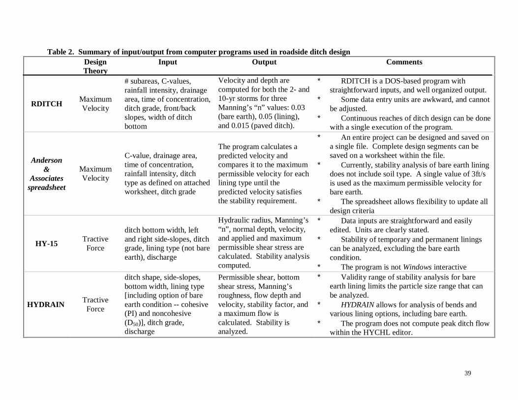
39
Table 2. Summary of input/output from computer programs used in roadside ditch designDesignTheory
Input Output Comments
RDITCHMaximumVelocity
# subareas, C-values,rainfall intensity, drainagearea, time of concentration,ditch grade, front/backslopes, width of ditchbottom
Velocity and depth arecomputed for both the 2- and10-yr storms for threeManning’s “n” values: 0.03(bare earth), 0.05 (lining),and 0.015 (paved ditch).
∗ RDITCH is a DOS-based program withstraightforward inputs, and well organized output.
∗ Some data entry units are awkward, and cannotbe adjusted.
∗ Continuous reaches of ditch design can be donewith a single execution of the program.
Anderson&
Associatesspreadsheet
MaximumVelocity
C-value, drainage area,time of concentration,rainfall intensity, ditchtype as defined on attachedworksheet, ditch grade
The program calculates apredicted velocity andcompares it to the maximumpermissible velocity for eachlining type until thepredicted velocity satisfiesthe stability requirement.
∗ An entire project can be designed and saved ona single file. Complete design segments can besaved on a worksheet within the file.
∗ Currently, stability analysis of bare earth liningdoes not include soil type. A single value of 3ft/sis used as the maximum permissible velocity forbare earth.
∗ The spreadsheet allows flexibility to update alldesign criteria
HY-15TractiveForce
ditch bottom width, leftand right side-slopes, ditchgrade, lining type (not bareearth), discharge
Hydraulic radius, Manning’s“n”, normal depth, velocity,and applied and maximumpermissible shear stress arecalculated. Stability analysiscomputed.
∗ Data inputs are straightforward and easilyedited. Units are clearly stated.
∗ Stability of temporary and permanent liningscan be analyzed, excluding the bare earthcondition.
∗ The program is not Windows interactive
HYDRAINTractiveForce
ditch shape, side-slopes,bottom width, lining type[including option of bareearth condition -- cohesive(PI) and noncohesive(D50)], ditch grade,discharge
Permissible shear, bottomshear stress, Manning’sroughness, flow depth andvelocity, stability factor, anda maximum flow iscalculated. Stability isanalyzed.
∗ Validity range of stability analysis for bareearth lining limits the particle size range that canbe analyzed.
∗ HYDRAIN allows for analysis of bends andvarious lining options, including bare earth.
∗ The program does not compute peak ditch flowwithin the HYCHL editor.
40
The initial program developed by FHWA, called HY-15, employs the tractive force method for
stability analysis of flexible and concrete ditch linings, as presented in FHWA HEC-15 (1988).
The program, based in DOS, is user intuitive and has the capability for the user to modify most
data entries on a continuous basis. The program is useful in checking stability using maximum
allowable tractive force for simple, lined roadside ditches. However, storm discharges cannot be
calculated within the program and stability of bare earth ditches cannot be evaluated. Overall,
the program is a useful design tool, but limited in applications.
The HYDRAIN Integrated Drainage Design Computer System is a powerful design tool
developed by the FHWA. Various aspects of drainage design can be accomplished using the
HYDRAIN package, including hydrological analysis, storm drainage design, step backwater,
bridge hydraulics, culvert design, and roadside channel design. The roadside channel design
submenu, HYCHL, can calculate flow depth, velocity and stability for a given channel and
design flow rate. This DOS-based software package is programmed to check channel stability
using the Maximum Permissible Tractive Force Theory presented in HEC-15 (1988). Complex
channel shapes, and temporary and permanent linings (including riprap design) can be analyzed
in HYDRAIN. Unlike HY-15, the bare earth lining condition can be analyzed in HYDRAIN.
When applied correctly, this program can be a useful design tool using the tractive force method.
Unfortunately, HYDRAIN uses equations to calculate maximum permissible shear stress for the
noncohesive bare earth condition that are valid only for larger particle sizes, at least 30 mm (1.18
in.) in size. Using the soil descriptions listed in the current VDOT maximum velocity chart, the
particle sizes for most soils described are outside the range of validity for these equations. Large
inaccuracies in design can occur with improper use of the equations programmed in HYDRAIN,
especially when designing with small particle sizes. Through trial, it was found that the
Maximum Allowable Velocity Approach and the Tractive Force Method begin converging for
characteristic particle sizes greater than 5 mm in diameter. Information concerning validity
ranges between particle size and maximum permissible tractive stress for finer grained particles
needs to be included in the program.
41
CHAPTER 4. COLLECTION AND UTILIZATION OF DATA FOR DESIGN
4.1 BackgroundThe design process of a stable roadway ditch includes the ability of the designer to accurately
model the hydrological response of the site draining to the ditch, appropriately apply this data
(10-year storm) to hydraulic design, and to accurately determine the stability (using the 2-year
storm) of the natural earth lining comprising the ditch line, and the stability of synthetic lining,
when required. For the ditch to perform as intended, the ditch design must then be successfully
constructed and maintained for the design storm flows.
Errors occurring during any part of this process can be the cause of an improper calculation of
ditch capacity or an erosion failure. Inaccuracies in the design of roadway ditches can lead to
ditches that are either overly or under conservative. Both cases result in ditches that are more
costly than necessary. Overly conservative designs require increased construction effort and
acquisition of required right-of-way. Under conservative design of ditches can result in erosion
failures and consequent costly repairs.
4.2 Methods
To determine the state of practice, both design and construction related, of roadside ditch design,
each of VDOT’s nine districts was visited to survey current design practice and to assess the
personnel’s experience and opinions related to the local state of roadside ditch performance. At
each meeting VDOT personnel from the Construction, Environmental, Location and Design
(Hydraulics), Maintenance, and Materials Divisions participated in the discussions. The content
of these interviews can be found in Question/Response form in Appendix A.
Reference material released by Virginia were surveyed to learn the current established policy and
procedures for soil data collection and reporting, and the design practice for hydrological and
hydraulic analysis of roadside ditches.
Because North Carolina has similar soil types as parts of Virginia, a meeting was scheduled with
North Carolina Department of Transportation in the Mount Airy District. The intent of this
meeting was to learn the general roadway ditch design process, erosion control techniques used
42
in North Carolina, and to understand how NCDOT handles problematic soils, especially
micaceous soils, during roadway construction.
4.3 Results
4.3.1 Collection and Reporting of Soil/Rock DataFrom discussions with VDOT personnel at each district is was learned that practices for the
collection and use of soil/rock data reports vary widely across the state, and often consist of the
minimum recommended practice by the state, or less. Data and soil conditions found in the field
are compiled into a report for distribution to various roadway designers. The content and format
of the soils reports, as prepared by the Materials Division in accordance with Virginia procedure
outlined in the Manual of Instructions (1995), are geared to present data for applications of
roadway design, excluding ditch design. It was reported from the Districts that the soils report
for a project often is made available, if at all, to the hydraulic designer only after substantial
design of roadway ditches.
4.3.2 Hydraulic and Hydrological AnalysisIt was learned from discussions with VDOT hydraulic engineers that the current hydraulic design
practice of roadside ditches, in most districts, relies heavily on established default design criteria.
When practiced, default design criteria are applied uniformly and consistently on all projects.
Default design criteria were found to be used in all aspects of ditch design, from determination of
peak flow to stability analysis. This standardization of design depreciates the importance of site
specific characteristics that are present on each project.
4.3.3 Geographical and Management FactorsFrom discussions with VDOT personnel it was learned that certain conditions exist that may
contribute to inaccuracies in design and construction, possibly causing erosion failures. These
conditions, grouped as geographical and management factors, include certain geographical
features not currently incorporated in ditch design, enforcement of stormwater management,
construction contract provisions, acquisition of roadway right-of-way, and District participation
in Central Office and consultant project designs.
4.4 Discussion
4.4.1 Collection and Reporting of Soil/Rock DataComplete and accurate knowledge of geologic conditions is essential for the safe and economical
design of roadway structures. The design of roadways relies heavily on the ability to accurately
43
predict geologic conditions, both topographic features as well as subsurface features.
Topographic features may influence the placement of the road alignment, while subsurface
conditions may influence slope and pavement designs. Accurate collection and distribution of
subsurface soil/rock data is necessary for the design of reliable and economical roadways.
The reliable and economic design of roadway ditches is similarly influenced by complete and
accurate knowledge of geologic conditions. During construction, stability of roadway ditches is
critical. The ability of the designer to accurately determine temporary lining needs, if any, is
dependent on the reliable classification of soil type comprising the lining. False stability
determinations can result in either erosion failure, or the application of a geosynthetic liner to a
ditch capable of withstanding the design flow.
The Materials Division of the Virginia Department of Transportation is responsible for providing
engineering assistance to design units through field sampling, inspection, testing, and control of
materials incorporated in the construction or maintenance of highways, structures, bridges and
incidentals (Manual of Instructions, 1995). This Division is responsible for collecting and
reporting subsurface information, and providing preliminary engineering assistance to design
units in the form of a final soil survey report (Manual of Instructions, 1995). The purpose, in
part, of a final soil survey is to locate and identify the various soil/rock types within the project
limits, provide representative samples of each soil type for testing, and identify any geologic
conditions that may have an adverse effect on the project. The final soil survey is to be
conducted in general accordance with AASHTO T86 - "Recommended Practice for Investigating
and Sampling Soils and Rock for Engineering Purposes" (Manual of Instructions, 1995).
The procedures outlined in the Material Division’s Manual of Instructions sets forth the
minimum procedures for geologic exploration of project sites and are to be followed in order to
achieve uniformity in the control and use of materials throughout the State. The minimum
explorations vary depending on grading (dependent or independent), and the presence of
saturated or unsuitable material. On sections where independent grading is required, one point
must be drilled at 100 m intervals on each lane. The drill point is at the centerline of the uphill
ditch. For sections where dependent grading is required, the points must be drilled at 100 m
intervals at points located on the outside ditch of each lane and at the center of the median. In
either grading condition, if saturated or unsuitable material is encountered, borings should be
44
made at 50 m intervals along at the same points on the cross-section as outlined above. All
points mentioned should be drilled at least 1.5 m below finished grade. In the event that the
geological conditions found in adjacent borings vary greatly, intermediate borings may be
necessary to characterize the situation accurately. As borings are being made, samples weighing
approximately 100 grams should be taken at 1.5-meter intervals for determination of field
moisture content. Upon completion of the soil survey, the District Materials engineer shall
prepare a complete report with laboratory test reports, noting field conditions and any
recommendations. The report is delivered to the division that requested the investigation.
(Manual of Instructions, 1995)
The current minimum practice for geologic investigation spaces borings greater than the design
reach of roadside ditches. The minimum drilling practice spaces borings typically on 100 m
intervals, with a minimum guideline of 50 m in unsuitable material. The decision to decrease
boring spacing is made by the attending Geologist based on site conditions. Hydraulic design
guidelines specify that roadway ditches be designed on 30 m (100 ft) intervals (Virginia 1989).
The current drilling procedure outlined above does not provide the hydraulic engineer with
adequate soils data from the field to perform stability analyses along each design reach. The
minimum guideline for spacing in suitable materials of 100m is more than three times the design
reach for a hydraulic designer. Surveyed VDOT personnel indicated that often the minimum
drilling procedure, or even less, is generally practiced. As a result, soils data available to
roadway ditch designers is minimal.
Borings are taken along a road alignment to document soil and rock conditions. Between
borings, interpolation is used to determine soil/rock conditions from nearby borings. The ability
to reliably interpolate between borings is dependent on the ability of the Geologist performing
the exploration to record soil/rock conditions encountered in the borings. This requires
considerable experience in field classification of soil and rock to distinguish changes that
identify distinct formations with depth in a single boring, and lateral changes between adjacent
borings. AASHTO T 86 states that a complete soil investigation should identify soil types with
the depth of their occurrence and recover representative disturbed samples of each subsurface
material for laboratory classification tests (AASHTO, 1990a).
45
From our survey of VDOT Materials personnel, it was learned that representative samples are
not being recovered from borings in most Districts. Common sampling practices in the Districts
involve recovering samples from an auger flight. Sampling techniques using the auger flight
include sampling soil deposited on the ground by a rotating auger, or by taking grab samples
from an auger flight that has been lifted from the boring hole without rotation. Either sampling
technique produces samples not representative of actual subsurface conditions as a result of
mixing of soil layers by the rotating auger. Inaccurate determination of soil formations with
depth in the boring log is a result of this sampling technique.
Despite the geologic data available through the soil survey report, it was learned from VDOT
hydraulic engineers that actual field data is seldom used in roadway ditch design. Reasons stated
by VDOT hydraulic designers for not using available site data in designs include incomplete
reporting of soil conditions and untimely arrival, if at all, of the soil survey report during ditch
design.
The surveyed District hydraulic design personnel indicated that the format of the final soil survey
is not geared for applications to ditch design. The main objective of the geotechnical
investigation is “to acquire data for the design of roadway foundations, cut and fill slopes, soil
stabilization and retaining systems, and structure foundations” (Virginia 1995). In meeting this
objective, emphasis is not placed on the application of the acquired data to roadway ditch design.
Only the Lynchburg, Northern Virginia, and Staunton districts present soil stratigraphy (useful to
the drainage ditch designer), station by station along the roadway, in the final soil survey report.
Despite the valuable soil/rock information in the reports of these Districts, the use of actual field
conditions in ditch design is still very limited.
In general, the predominant reason, indicated by surveyed personnel, that actual field conditions
are not used in the design of drainage ditches is due to late distribution, if at all, of the final soil
survey to the hydraulic engineers. Common practice is for the hydraulic designer to receive a
copy of the report after substantial completion of drainage design. In several cases, the Materials
Division was unaware of the hydraulic engineer’s need for the final soil survey and had not been
directly distributing the report to the ditch designer.
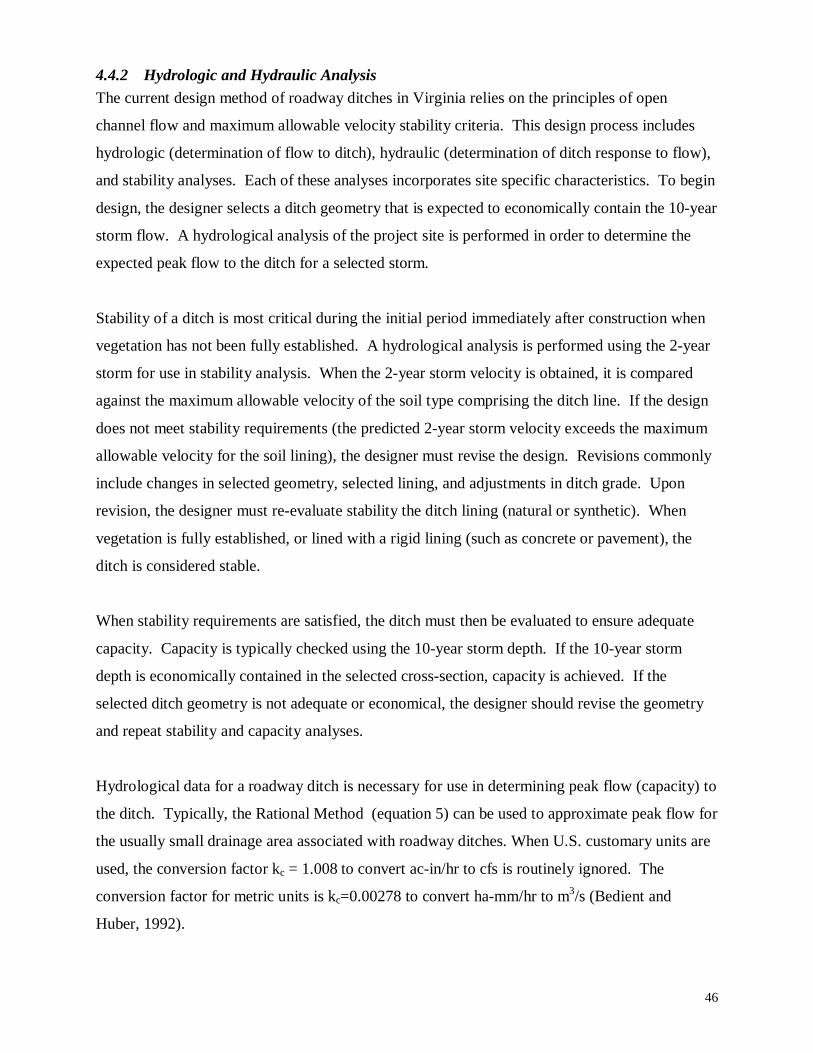
46
4.4.2 Hydrologic and Hydraulic Analysis
The current design method of roadway ditches in Virginia relies on the principles of open
channel flow and maximum allowable velocity stability criteria. This design process includes
hydrologic (determination of flow to ditch), hydraulic (determination of ditch response to flow),
and stability analyses. Each of these analyses incorporates site specific characteristics. To begin
design, the designer selects a ditch geometry that is expected to economically contain the 10-year
storm flow. A hydrological analysis of the project site is performed in order to determine the
expected peak flow to the ditch for a selected storm.
Stability of a ditch is most critical during the initial period immediately after construction when
vegetation has not been fully established. A hydrological analysis is performed using the 2-year
storm for use in stability analysis. When the 2-year storm velocity is obtained, it is compared
against the maximum allowable velocity of the soil type comprising the ditch line. If the design
does not meet stability requirements (the predicted 2-year storm velocity exceeds the maximum
allowable velocity for the soil lining), the designer must revise the design. Revisions commonly
include changes in selected geometry, selected lining, and adjustments in ditch grade. Upon
revision, the designer must re-evaluate stability the ditch lining (natural or synthetic). When
vegetation is fully established, or lined with a rigid lining (such as concrete or pavement), the
ditch is considered stable.
When stability requirements are satisfied, the ditch must then be evaluated to ensure adequate
capacity. Capacity is typically checked using the 10-year storm depth. If the 10-year storm
depth is economically contained in the selected cross-section, capacity is achieved. If the
selected ditch geometry is not adequate or economical, the designer should revise the geometry
and repeat stability and capacity analyses.
Hydrological data for a roadway ditch is necessary for use in determining peak flow (capacity) to
the ditch. Typically, the Rational Method (equation 5) can be used to approximate peak flow for
the usually small drainage area associated with roadway ditches. When U.S. customary units are
used, the conversion factor kc = 1.008 to convert ac-in/hr to cfs is routinely ignored. The
conversion factor for metric units is kc=0.00278 to convert ha-mm/hr to m3/s (Bedient and
Huber, 1992).
47
“Due to assumptions regarding the homogeneity of rainfall and equilibrium condition at the time
of peak flow, the rational method should not be used on areas larger than about 1 mi2 (2.5 km2)
without subdividing the overall catchment into subcatchments and including the effect of routing
through drainage channels.” (Bedient and Huber, 1992). Because rainfall intensity is not
homogeneous (varies over time and space), the Rational Method will become more conservative
(tendency to over-predict) peak flow for larger drainage areas, due to this underlying assumption.
The runoff coefficient, C, accounts for any runoff losses (ex. infiltration) that occur within a
given drainage area, typically given as a function of land use. The runoff coefficient for drainage
areas is an indication of the percent of rainfall volume that becomes runoff and a characteristic of
the drainage area. Tables have been compiled providing runoff coefficients for various land
uses. When more than one land use occurs within the same drainage area, common practice is to
develop an area-weighted runoff coefficient accounting for each land use within the total
drainage area. One of the “principle fallacies” of the Rational Method is the assumption that a
single value for the runoff coefficient can be associated with a drainage area, despite total rainfall
volume or antecedent conditions (Bedient and Huber, 1992). This assumption holds more
accurate for predominately impervious land uses.
Rainfall intensity, i, is obtained from IDF (Intensity-Duration-Frequency) Curves for a given
area, specified return period, and duration time. In Virginia, IDF curves are available for each
county. Time of concentration, tc, is commonly assumed to equal the duration time. “This
assumption is physically realistic because the time of concentration also is the time to
equilibrium at which time the whole catchment contributes to flow at the outfall” (Bedient and
Huber, 1992). Proper evaluation of tc is critical because rainfall intensity is inversely
proportional. The kinematic wave equation should be used to calculate time of concentration
(Bedient and Huber, 1992).
Drainage area, A, should be determined based on available geographical information, such as
topographic maps. Because drainage areas are often unsymmetrical in shape and difficult to
quantify, a simplification to aid in the determination of area is to use rectangular strips to
approximate drainage area. This method, known as width-of-strip, allows the designer to
determine the width of a rectangle that best approximates the drainage area for a given length.
Area can then be easily calculated.
48
In roadway design, the drainage area associated with roadside ditches is commonly divided into
three subareas to account for land uses: pavement, shoulder and ditch line, and area outside the
right-of-way. Due to geometric nature of the roadway structure, land use area approximations
within the roadway right-of-way (pavement, shoulder and ditch line) are typically easily attained.
Area approximations outside the roadway right-of-way generally rely on the engineering
judgement of the designer due to variability of the landscape, see Figure 4.1.
The survey of VDOT design engineers revealed that hydrological analysis involved in roadway
ditches is widely performed across the state using the Rational Method, though in many
instances loosely applied. As recommended for more accurate calculations using the Rational
Method, District designers typically subdivide the drainage area of the roadway ditch and apply
weighted runoff coefficients to account for various land uses comprising the area. Because land
use runoff coefficients and area computation within right-of-way are typically easily computed,
proper determination actual drainage area and land uses for the area outside the right-of-way
become critical to the peak flow calculation. Methods for delineating drainage area and
determining runoff coefficients for this area vary widely across the state.
Figure 4.1 Typical drainage area components of a roadway ditch; area outside of right-of-way approximated by width-of-strip method.
Typically topographic maps of the drainage area are used to delineate the watershed. Aerial
photos and/or site visits can be used to assess landuse. However, from VDOT design engineers
it was learned that some engineers in the state are not rigorously accounting for the drainage area
and land uses for the drainage area outside the roadway right-of-way. In some instances, VDOT
Dra
inag
e ar
ea o
utsi
deo
f rig
ht-o
f-w
ay
Ro
adw
ay
sho
uld
er a
nd d
itch
Ro
adw
ay
sho
uld
er a
nd d
itch
Dra
inag
e ar
ea o
utsi
deo
f rig
ht-o
f-w
ay
Pavement
49
designers were reported to set a maximum width-of-strip for this area at some arbitrary value,
ranging from 100-200 ft. Sometimes this default maximum width would be applied without
initially consulting a topographic map and, in some instances, despite actual drainage area
delineation. Additionally, it was learned that other designers rely entirely on site inspection to
delineate the drainage area for the ditch. Applying these design practices to roadside ditch
design can result in inaccuracies in the determination of peak flow. Because drainage area is
directly proportional to peak flow, the underestimation of drainage area results in the
underestimation of peak flow. Consequently, ditches may be under-designed for a specific
design storm.
Generally runoff coefficients for the areas within the right-of-way (roadway pavement, shoulder
and drainage ditch) can be easily applied. The area outside the right-of-way can consist of
various land uses and, therefore, be further subdivided to best develop a weighted a runoff
coefficient. From District interviews, it was learned that some VDOT engineers have established
runoff coefficients for the area outside the right-of-way that are applied consistently for all
projects. Inadequately accounting for runoff coefficients can lead to inaccuracies in the
prediction of peak flow. Consequently, capacity and stability checks may be inaccurate.
The time of concentration is used to enter the IDF curve to obtain a rainfall intensity for a
specific storm. Because time of concentration is inversely proportional to rainfall intensity,
accurate determination of time of concentration is critical. Interviews with VDOT hydraulic
engineers revealed that often a default 5-minute time of concentration is used in ditch design.
The rationale behind this approach is that 5 minutes is the most conservative time of
concentration. However, overly conservative approximations of time of concentration result in
larger rainfall intensity, and consequently increased predicted flow to the roadway ditch. This
type of inaccuracy in predicting peak flow results in the over design of roadway ditches.
Once peak flow for a desired storm frequency has been established, ditch shape and geometry is
then determined. Using Manning’s formula flow depth and velocity can be determined for the
desired storm as function of ditch shape, slope, and hydraulic roughness. An inverse relationship
between hydraulic roughness and velocity makes accurate determination of the hydraulic
roughness coefficient critical. Smaller roughness coefficients indicate smoother surfaces
generating a faster flow velocity.
50
Hydraulic roughness coefficient should be selected based on the ditch lining. The current VDOT
practice is to apply a single hydraulic roughness coefficient for each lining condition
independent of project location: rigid linings (n = 0.015); nonrigid linings, including vegetated
and synthetic linings (n = 0.05); and bare earth (n = 0.03). This practice is promoted in the
Virginia Drainage Manual (1989) through the use of nomograph solutions to Manning Equation.
These nomograph charts utilize three axes, one for each of the default Manning’s n values.
Solutions of flow depth and velocity using Manning’s Equation can be obtained faster and more
easily using these charts because no hand calculations are necessary. Hand calculations,
however, are necessary for solving Manning’s Equation using other hydraulic roughness
coefficients.
The current VDOT practice of assigning default hydraulic roughness coefficients diminishes the
importance of site variability of soil type associated with bare earth linings. Many parameters,
including liner type, particle size and shape, compaction, channel shape or geometry,
meandering, etc., can all influence hydraulic roughness. Suggested roughness coefficients for a
variety of ditch conditions are listed in Table 2.8.2 of the Virginia Drainage Manual). From this
table, the current default value of 0.03 used in Virginia for “bare earth” corresponds to
descriptions of ditch conditions such as "grass, some weeds", "dense weeds in deep channels",
and "gravel or cobble bottom". Table 2.8.2 lists several "natural lining" or bare earth categories
with recommended roughness coefficients ranging from 0.016 to 0.025.
Virginia classifies synthetic liners into three categories (EC-2, EC-3a, and EC-3b) by
performance parameters. Each class of lining represents increased resistance to flow and
erosion. Because products in this class are constructed differently to withstand flow velocity, it
is probable that hydraulic roughness coefficients for each class may vary as well. Product
manufacturers provide the only available data for design.
The final step in the design of roadway drainage ditches is the stability analysis of the ditch
lining. The 2-year storm velocity is compared against a maximum allowable velocity for the soil
comprising the bare ditch. Recommended maximum allowable velocities for earth linings are
presented in Table 2.8.1 of the Virginia Drainage Manual (1989). If the predicted 2-year
51
velocity exceeds the maximum allowable velocity for the soil, then stability is not met and
erosion failure may result.
Accurate determination of stability requires accurate determination of soil type comprising the
ditch lining and the ability to relate this data to a maximum allowable velocity. From VDOT
hydraulic designers, it was learned that stability of unlined ditches is commonly determined
without the use of soils data. Often stability of unlined ditches is based on a single default
maximum allowable velocity, independent of soil type. The default value varies by District,
ranging from 1.5 ft/sec to 6 ft/sec, and is consistently applied within each District. The hydraulic
engineers surveyed indicated several reasons this default criterion is practiced including late
arrival, if at all, of the Materials Division soils report, incomplete reporting of soil data
comprising the ditch line, and an absence recommended maximum allowable velocities for
anticipated soils from Materials Division (Lynchburg District is a notable exception).
Questions recently have been asked regarding the appropriate maximum allowable velocities to
apply to synthetic linings. VDOT categorizes synthetic liners into three classes based on
performance parameters (EC-2, EC-3a, and EC-3b). Each class of lining represents increased
capability to resist design flow. However, it was learned that there is little consistency between
Districts on the maximum allowable velocity to apply to each class of linings. Manufacturers of
these products contain the only available data for design.
4.4.3 Geographical and Management Factors
The survey of district personnel revealed that unexpected factors contribute to the occurrence of
roadside ditch erosion. These factors include geographical and management issues which
current VDOT policy and procedures do not explicitly manage.
Geographical features can be assessed regionally by geomorphological changes across the state.
In the eastern part of the state, roadside ditch designs are impacted by tidal fluctuations and very
mild slopes. Tidal fluctuations, currently not incorporated into ditch design, can affect capacity
and stability performance. Ditch performance in the central regions is impacted by the behavior
of micaceous soils and the degradation of rock subgrades. The western part of the state is
impacted by long steep grades and acidic soil conditions. (Fredericksburg District also reports
complications with acidic soils.) A better understanding of how these conditions and their
influence on roadside ditch performance can enhance ditch design.
52
Management factors represent process issues affecting both design and construction of roadway
ditches. These issues were mentioned at almost all the District interviews indicating that
Districts are being impacted somewhat evenly by these issues. These factors include
enforcement of stormwater management regulations on private developments, acquisition of
roadway right-of-way, construction contract provisions, and district participation in Central
Office and consultant project designs.
Complaints of inadequate stormwater management of private developments seemed to be a
serious concern for VDOT personnel. Unchecked drainage from these developments enters the
roadway ditches, becoming the responsibility of VDOT. This increased flow in the roadway
ditches from private development often exceeds the design flow for the ditch resulting in erosion
failures and sedimentation. These costly failures are repaired by VDOT Construction and
Maintenance personnel, expending valuable VDOT resources.
The adequate acquisition of roadway right-of-way for road upgrades or new road construction
has been expressed by some VDOT personnel as being a limiting factor in design and
performance of roadway ditches. Either for political or economic reasons, right-of-way
acquisition has been so limited that, at times, has been barely sufficient to accommodate the
travel lanes. Consequently roadway ditches, utilities, and light and sign pedestals are crowded
into the little space remaining. Roadway ditches in these instances often have steep sideslopes,
which may become unstable. Also, utilities get buried along the ditch lining, while sign and light
pedestals have been seen placed within the ditch conveyance, obstructing flow. These conditions
have resulted in poor ditch performance.
Current contract language by VDOT treats erosion control measures, including mulching and
seeding, as task-based activities. Once the contractor has performed the task, in general they
have fulfilled the intent of the contract item. VDOT personnel have complained that this
approach, especially with regard to seeding and mulching, transfers the costs of adequate
vegetation establishment from the contractor to the VDOT Maintenance and Construction
Divisions. Contractors, under these task-based contracts, often postpone mulching and seeding
of the construction site until the end of the project. With this approach, vegetation has not been
53
established, however the contract obligation of seeding and mulching has been achieved, and the
contractor upon project completion is cleared to leave the site.
North Carolina has established several contract clauses to address this issue. To entice
contractors to perform permanent seeding and mulching on a project as soon as practical after
slopes or portions of the slopes have been graded (not as a task at the end of a project), North
Carolina construction contracts include “seeding incentives” clauses. As part of these clauses the
contractor receives a percent additive to the base unit price for “Seeding and Mulching”
depending on when this task is accomplished with respect to total elapsed contract time. When
elapsed contract time is between 0-30%, the percent additive is 30% to the base unit price. If this
task is completed between 30-50% of elapsed project time, the percent additive drops to 15%.
No additive is paid after total elapsed project time exceeds 50%. This clause helps NCDOT to
establish vegetation prior to accepting the project and contractor leaving the site.
To establish a plan to pro-actively prevent erosion failures on construction sites, North Carolina
construction contracts also include a clause called “Response for Erosion Control”. This clause
assures payment for the actual number of times the erosion control contractor moves onto the
project, at the engineer's request, to perform repair, temporary, or permanent erosion control
work. Under conventional contract agreement, the contractor includes a limited number of
erosion control contractor mobilizations. Once this limited number of erosion control
mobilizations in the base bid is utilized, it is unlikely that the erosion control contractor will be
recalled to the site to address because the expense was not budgeted. The contract clause
“Response for Erosion Control” ensures payment to the contractor for any additional erosion
control mobilizations necessary. This clause provides incentive for the contractor to address
erosion control issues as needed by ensuring payment for their work, while also helping NCDOT
to pro-actively prevent erosion on construction sites.
The final management issue focuses on the amount of involvement local District personnel have
in Central Office and consultant projects. Many VDOT District personnel feel more
involvement from local personnel on Central Office and consultant projects will provide valuable
insight to soil conditions and erosion control issues unique to their District during the design
process, and result in fewer field modifications during construction of these designs. District
personnel often have to address field modifications when projects from Central Office and

54
consultants designed by engineers not local to the project area and unaware of local conditions
go to construction. These modifications often involve adjustments necessary to accommodate
unique erosion control issues based on local conditions. Increased District involvement can
reduce the time and expense associated with field modification under these circumstances.
55
CHAPTER 5. SYNTHESIS OF DESIGN CRITERIA
5.1 Background
Understanding the interaction between flowing water and its boundary is critical to the
appropriate design of earthen hydraulic structures, such as roadside ditches. In the design of
roadside ditches, this interaction becomes visible through two primary features: the selection of a
hydraulic roughness coefficient and the application of stability criteria for a given soil
type/lining.
5.1.1 Hydraulic Roughness Coefficients
In the application of Manning’s formula, the hydraulic roughness coefficient is a measure of the
resistance the boundary offers to flow. Hydraulic roughness is a function of many ditch
properties; consequently, the relationship between flowing water and the roughness of its
boundary is not easily defined. Research to better quantify this relationship has been in progress
for many years. As early as 1923, Strickler attempted to characterize Manning’s roughness using
sediment diameter. Reports and technical papers suggest that the roughness coefficient, n, may
be a function of 8 – 10 parameters (Yen, 1992). Six primary factors used in estimating
Manning’s n value are grain roughness, irregularity of the surfaces of the channel sides and
bottom; variation in shape and size of cross sections; obstructions; vegetation; meandering
(Cowan, 1956). Because any one of these features may influence flow more significantly than
others, each ditch possesses a unique roughness characteristic. Hydraulically, it is important to
distinguish flow boundaries as being natural (earthen), flexible, or rigid. Boundary flexibility
and porosity will modify the flow velocity distribution near the boundary and, consequently, the
resistance.
For earthen channels, properties of the soil lining (including particle size, shape, orientation to
flow, compaction, etc.) greatly influence hydraulic roughness. Because many parameters can
affect hydraulic roughness, many methods have been used to characterize Manning’s n. Particle
size has the most influence on hydraulic grain roughness and has been widely used to
characterize hydraulic roughness for bare soil conditions. Typically D50 (diameter for which 50
percent of the particles are finer in a given sample) is a statistical property of a soil grain size
distribution which has been used to predict hydraulic roughness (Strickler, 1923). However,
56
because larger particles project further into the flow field, it seems that larger particle diameters
are better suited for characterizing Manning’s n. For example, Meyer-Peter and Muller (1948)
recommend D90 as a more appropriate size for characterizing grain roughness. Another method
uses a base roughness coefficient to account for grain roughness and then adds modifiers to
account for other roughness elements based on visual inspection (Cowan, 1956). Also, flow
depth has been found to have an effect hydraulic roughness for the case of relatively shallow
flows (HEC-15, 1988). As flow becomes shallower, roughness elements can provide increased
resistance to flow.
When needed, synthetic linings can be placed onto the ditch boundary to increase a ditch’s
resistance to erosion. While erosion resistance is increased, the selected temporary synthetic
lining also typically increases the hydraulic roughness of the ditch. Hydraulic roughness can be
significantly affected by the class of lining, both temporary and permanent, selected by the
designer. Manufacturers of temporary linings (example: jute mesh) publish Manning’s n values
for each of their products. Because such products are continuously being created and revised by
manufacturers, care must be taken to ensure that the most current value of Manning’s n for a
particular product is used for design. Inaccurate approximations of Manning’s n can greatly
affect the predicted design velocity of a ditch, and may result in erosion failure.
Vegetation (typically grass) is the preferred permanent lining for roadside ditches. Vegetated
linings provide an economical and low maintenance lining option, since they tend to retard the
flow near the boundary and strengthen the soil stability through their root system. Hydraulic
resistance of vegetated linings is related to blade stiffness, growth height, and plant density.
Ideally, Manning’s n should be calculated as a function of all these properties.
When bare earth and temporary linings are predicted to be unstable (prone to erosion), rigid
linings may be necessary. Rigid linings (permanent) are concrete/paved linings that
characteristically generate high flow velocities. Because the boundary roughness of the
concrete/paved lining is not extremely variable from site to site, approximating hydraulic
roughness for these structures is less difficult.
57
5.1.2 Stability Criteria
Historically, maximum allowable velocity criteria for unlined and lined irrigation canals were
developed in the 1920’s from a survey of Irrigation Engineers (Fortier and Scobey, 1926). “The
pioneering work of Fortier and Scobey was the basis of channel design for many years; however,
it is a design methodology based primarily on experience and observation rather than physical
principles” (French, 1985). The results of Fortier and Scobey’s research were distilled into a
table that lists maximum allowable water velocities for different types of soils in which irrigation
canals were constructed. It was compiled on the basis of information from many Irrigation
Engineers in the West and Southwest regions of the United States and relied on the USDA
Textural system for descriptions of soils. A ditch is considered stable against erosion if the
predicted water velocity is less than the recommended maximum allowable water velocity of the
boundary soil.
The maximum allowable velocity criteria developed by Fortier and Scobey have been used to
design irrigation channels and other earthen hydraulic structures for decades. However, many
differences exist between the basis and intended use of the Fortier and Scobey table and the
application of this table to roadway drainage ditch design in Virginia. AASHTO soil
classification, mandated by VDOT for use in Virginia, provides more precise soil classifications
than USDA soil descriptions. Data used in compiling the Fortier and Scobey table was collected
in the western regions of the U.S., where soil conditions can differ considerably from soil
conditions in Virginia. The USDA Textural soil descriptions used by Fortier and Scobey are
vague, making conversion to AASHTO soil classifications difficult. Irrigation channels tend to
be larger, and consequently may be constructed differently. Also, they usually have sustained
flows while roadside ditches have intermittent flows. For these reasons, caution must be used in
extrapolating the results of Fortier and Scobey’s survey to roadside drainage ditch applications in
Virginia.
The current state of practice in Virginia of relating soil type and maximum allowable velocity for
roadside ditch design is to refer to a table adapted from the 1926 Fortier and Scobey survey
(Table 3. – Table 2.8.1 in the Virginia Drainage Manual). It was adapted from the original
Fortier and Scobey table with few modifications, such as equating a few of the USDA textural
soil descriptions with AASHTO soil classifications.
58
The State of Virginia contains five geological regions within its borders – the Coastal, Piedmont
Blue Ridge, Valley and Ridge, and Appalachian Plateau. Within each region a variety of soils
and soil conditions exist. Individual VDOT Construction Districts have, in some instances,
modified the maximum allowable velocities listed in Table 3 to reflect the local soil conditions
within their District.
The Tractive Force Method, based on scientific principles and presented in the FHWA
publication HEC-15 (1988), is used mainly for design of rip rap lined ditches in Virginia. This is
a more recently developed design theory, and represents the interaction between flowing water
and its boundary more closely. For a ditch to remain stable against erosion, the shear stress
exerted by flowing water should not exceed the predicted maximum permissible stress of the soil
boundary or lining.
5.2 Methods
As part of a literature review, various states’ drainage manuals were surveyed with the intent of
gaining a general understanding of the current use of Manning’s n values for roadside ditch
design. Also, a literature review of journal articles and various publications was performed to
learn the most recent findings regarding the determination of Manning’s n.
The current state of practice for stability design criteria of roadside drainage ditches has also
been investigated. Three approaches have been used to accomplish this task.
First, a literature search was performed to locate information on ditch design and erosion.
Next, on-site interviews were conducted with Drainage Engineers, Materials Engineers,
Environmental Managers and technicians from all nine VDOT Construction Districts. Because
North Carolina has similar soil types and conditions, a meeting was held with personnel of
similar backgrounds from the Mount Airy District of the North Carolina Department of
Transportation. The objective of the meetings in Virginia and North Carolina was to ascertain
how aspects of roadside ditch design, construction and maintenance are inter-related to ensure
ditch stability. These meetings were extremely helpful in determining the state of practice in
Virginia.
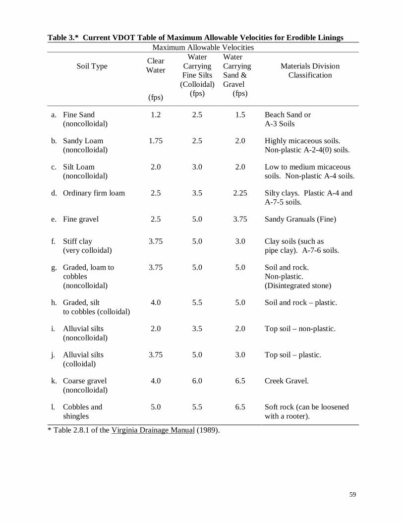
59
Table 3.* Current VDOT Table of Maximum Allowable Velocities for Erodible LiningsMaximum Allowable Velocities
Soil TypeClearWater
(fps)
WaterCarryingFine Silts
(Colloidal)(fps)
WaterCarryingSand &Gravel
(fps)
Materials DivisionClassification
a. Fine Sand(noncolloidal)
1.2 2.5 1.5 Beach Sand orA-3 Soils
b. Sandy Loam(noncolloidal)
1.75 2.5 2.0 Highly micaceous soils.Non-plastic A-2-4(0) soils.
c. Silt Loam(noncolloidal)
2.0 3.0 2.0 Low to medium micaceoussoils. Non-plastic A-4 soils.
d. Ordinary firm loam 2.5 3.5 2.25 Silty clays. Plastic A-4 andA-7-5 soils.
e. Fine gravel 2.5 5.0 3.75 Sandy Granuals (Fine)
f. Stiff clay(very colloidal)
3.75 5.0 3.0 Clay soils (such aspipe clay). A-7-6 soils.
g. Graded, loam to cobbles (noncolloidal)
3.75 5.0 5.0 Soil and rock.Non-plastic.(Disintegrated stone)
h. Graded, siltto cobbles (colloidal)
4.0 5.5 5.0 Soil and rock – plastic.
i. Alluvial silts(noncolloidal)
2.0 3.5 2.0 Top soil – non-plastic.
j. Alluvial silts(colloidal)
3.75 5.0 3.0 Top soil – plastic.
k. Coarse gravel(noncolloidal)
4.0 6.0 6.5 Creek Gravel.
l. Cobbles and shingles
5.0 5.5 6.5 Soft rock (can be loosenedwith a rooter).
* Table 2.8.1 of the Virginia Drainage Manual (1989).
60
Lastly, a review of drainage manuals from Virginia and other states was conducted. States
surrounding Virginia were especially targeted for this information. Drainage manuals from
various states were procured, where possible. Hydraulics personnel from other state DOTs were
also contacted directly to obtain information on erosion and design methodology.
5.3 Results
5.3.1 Hydraulic Roughness CoefficientsAccurate approximations of hydraulic roughness are important for determining the velocity of
flow and capacity of roadside ditches. The selection of the hydraulic roughness coefficient has a
significant influence on the predicted design velocity. When Manning’s n is under-estimated,
the predicted velocity will be larger than the actual velocity in the channel. When Manning’s n
is over-estimated, a smaller predicted velocity will result. When analyzing stability of a roadside
ditch, the higher the predicted velocity, the more conservative the estimate of stability.
Following this logic, it is more conservative to under-estimate hydraulic roughness. Typically,
stability analysis involves the need to approximate hydraulic roughness of the earthen lining, and
possibly synthetic temporary linings when needed. Because hydraulic roughness of temporary
synthetic lining products can be obtained from the manufacturer, approximating Manning’s n for
a bare earth soil lining can be critical.
Analysis of predicted design capacity is also influenced by deviations in hydraulic roughness
coefficients. Typically, analysis of design capacity is influenced by the selection of roughness
coefficient for the fully vegetated, or paved, lining condition. The smaller the selection of
hydraulic roughness coefficient for this lining condition, the faster the predicted velocity, and
consequently the smaller the required cross-sectional area. Therefore, the more conservative
(larger) capacity design would use a larger approximation of hydraulic roughness.
Manning’s n is an empirically derived value for channel cross sections developed without clearly
accounting for either wall roughness or movable alluvial bed (Yen, 1992). Various techniques
have been used in attempts to better quantify Manning’s n, especially for earthen and vegetated
channel linings. This section contains a literature review of some methods of characterizing
hydraulic roughness which are presented below by lining type.
61
Soil lined channels
Estimating hydraulic roughness for an earthen (unlined) channel can be difficult. Many
parameters, including particle size and shape, compaction, channel shape or geometry,
meandering etc., can all influence hydraulic roughness. Some researchers have chosen to
characterize Manning’s n by soil roughness, flow depth variation, or by choosing a base value
with modifiers to account for channel variance.
For non-cohesive soils, particle size has widely been used to characterize hydraulic roughness.
Because soils are rarely uniform in nature, a representative particle size has to be selected to
characterize roughness. Several sediment sizes have been proposed in literature for this purpose.
Statistically, D50 (particle diameter representing 50 percent finer particles in the given sample) is
readily available and meaningful. Physically, larger particles have a more pronounced effect on
flow resistance because they tend to project further into the flow field. For this reason, many
researchers have chosen to use a particle size greater than D50 to approximate hydraulic
roughness (Yen, 1992). A summary of various techniques to characterize Manning’s n for
unvegetated channels can be found in Table 4.
The earliest attempt to relate a roughness coefficient to a sediment property was made by
Strickler in 1923 (Yen, 1992). Strickler’s formula relates Manning’s n to the mean particle
diameter (D50) raised to the 1/6 power. This formula was based on data compiled from gravel-
bed streams and fixed-bed (no bedforms) channels and is not to be used where n changes
significantly with depth (Marcus et al, 1992). Many researchers have attempted to improve this
relationship, either through revisions of Strickler’s formula or by developing new formulas. For
example, Meyer-Peter and Muller (1948) developed an expression for Manning’s n based on a
larger particle size, D90 (diameter for which 90 percent of the particles are finer in a given
sample). Limerinos (1970) developed an expression relating both particle diameter and
hydraulic radius, partly capturing channel shape and flow depth effects, to hydraulic roughness.
A second approach for characterizing Manning’s n for bare earth is to characterize a roughness
coefficient for various soil types. Because a variety of soil types is found across the state, the
ability to relate a roughness characteristic to individual soil types would be valuable. To
implement this method, the designer would need to be provided with soil information prior to
design. This approach can be seen in a version of Fortier and Scobey’s maximum allowable
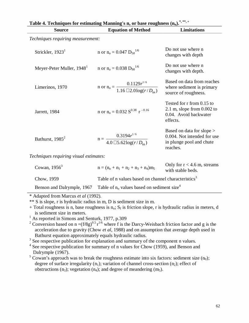
62
Table 4. Techniques for estimating Manning's n, or base roughness (no).*, **, +
Source Equation of Method Limitations
Techniques requiring measurement:
Strickler, 19231 n or no = 0.047 D501/6 Do not use where n
changes with depth
Meyer-Peter Muller, 19481 n or no = 0.038 D901/6 Do not use where n
changes with depth.
Limerinos, 1970 n or no = )/log(0.216.1
1129.0
84
6/1
Dr
r
+
Based on data from reacheswhere sediment is primarysource of roughness.
Jarrett, 1984 n or no = 0.032 S0.38 r - 0.16
Tested for r from 0.15 to2.1 m, slope from 0.002 to0.04. Avoid backwatereffects.
Bathurst, 19852 n = )/log(62.50.4
3194.0
84
6/1
Dr
r
+
Based on data for slope >0.004. Not intended for usein plunge pool and chutereaches.
Techniques requiring visual estimates:
Cowan, 19563 n = (no + n1 + n2 + n3 + n4)m5Only for r < 4.6 m, streamswith stable beds.
Chow, 1959 Table of n values based on channel characteristics3
Benson and Dalrymple, 1967 Table of no values based on sediment size4
* Adapted from Marcus et al (1992).** S is slope, r is hydraulic radius in m, D is sediment size in m.+ Total roughness is n, base roughness is no; Sf is friction slope, r is hydraulic radius in meters, d
is sediment size in meters.1 As reported in Simons and Senturk, 1977, p.3092 Conversion based on n =(f/8g)0.5 r1/6 where f is the Darcy-Weisbach friction factor and g is the
acceleration due to gravity (Chow et al, 1988) and on assumption that average depth used inBathurst equation approximately equals hydraulic radius.
3 See respective publication for explanation and summary of the component n values.4 See respective publication for summary of n values for Chow (1959), and Benson and
Dalrymple (1967).5 Cowan’s approach was to break the roughness estimate into six factors: sediment size (n0);
degree of surface irregularity (n1); variation of channel cross-section (n2); effect ofobstructions (n3); vegetation (n4); and degree of meandering (m5).
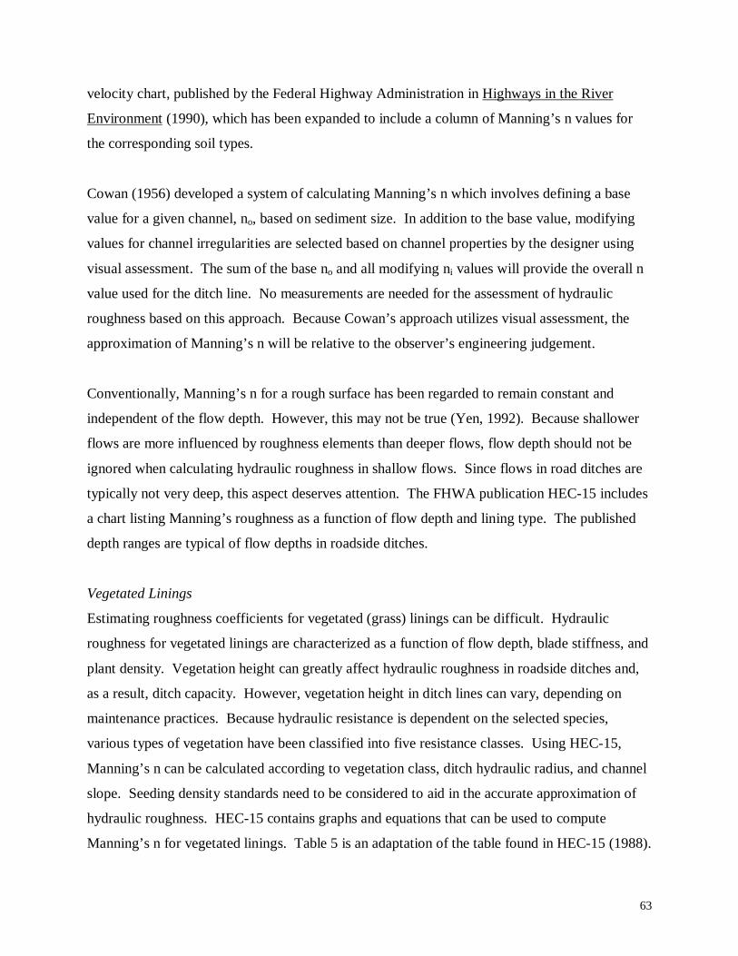
63
velocity chart, published by the Federal Highway Administration in Highways in the River
Environment (1990), which has been expanded to include a column of Manning’s n values for
the corresponding soil types.
Cowan (1956) developed a system of calculating Manning’s n which involves defining a base
value for a given channel, no, based on sediment size. In addition to the base value, modifying
values for channel irregularities are selected based on channel properties by the designer using
visual assessment. The sum of the base no and all modifying ni values will provide the overall n
value used for the ditch line. No measurements are needed for the assessment of hydraulic
roughness based on this approach. Because Cowan’s approach utilizes visual assessment, the
approximation of Manning’s n will be relative to the observer’s engineering judgement.
Conventionally, Manning’s n for a rough surface has been regarded to remain constant and
independent of the flow depth. However, this may not be true (Yen, 1992). Because shallower
flows are more influenced by roughness elements than deeper flows, flow depth should not be
ignored when calculating hydraulic roughness in shallow flows. Since flows in road ditches are
typically not very deep, this aspect deserves attention. The FHWA publication HEC-15 includes
a chart listing Manning’s roughness as a function of flow depth and lining type. The published
depth ranges are typical of flow depths in roadside ditches.
Vegetated Linings
Estimating roughness coefficients for vegetated (grass) linings can be difficult. Hydraulic
roughness for vegetated linings are characterized as a function of flow depth, blade stiffness, and
plant density. Vegetation height can greatly affect hydraulic roughness in roadside ditches and,
as a result, ditch capacity. However, vegetation height in ditch lines can vary, depending on
maintenance practices. Because hydraulic resistance is dependent on the selected species,
various types of vegetation have been classified into five resistance classes. Using HEC-15,
Manning’s n can be calculated according to vegetation class, ditch hydraulic radius, and channel
slope. Seeding density standards need to be considered to aid in the accurate approximation of
hydraulic roughness. HEC-15 contains graphs and equations that can be used to compute
Manning’s n for vegetated linings. Table 5 is an adaptation of the table found in HEC-15 (1988).
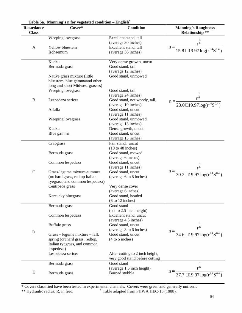
64
Table 5a. Manning’s n for vegetated condition – English+
RetardanceClass
Cover* Condition Manning’s RoughnessRelationship **
A
Weeping lovegrass
Yellow bluestemIschaemum
Excellent stand, tall(average 30 inches)Excellent stand, tall(average 36 inches) )Slog(r 19.9715.8
r n
4.01.4
6
1
+=
B
KudzuBermuda grass
Native grass mixture (littlebluestem, blue gammaand otherlong and short Midwest grasses)Weeping lovegrass
Lespedeza sericea
Alfalfa
Weeping lovegrass
KudzuBlue gamma
Very dense growth, uncutGood stand, tall(average 12 inches)Good stand, unmowed
Good stand, tall(average 24 inches)Good stand, not woody, tall,(average 19 inches)Good stand, uncut(average 11 inches)Good stand, unmowed(average 13 inches)Dense growth, uncutGood stand, uncut(average 13 inches)
)Slog(r 19.97 23.0
r n
0.41.4
6
1
+=
C
Crabgrass
Bermuda grass
Common lespedeza
Grass-legume mixture-summer(orchard grass, redtop Italianryegrass, and common lespedeza)Centipede grass
Kentucky bluegrass
Fair stand, uncut(10 to 48 inches)Good stand, mowed(average 6 inches)Good stand, uncut(average 11 inches)Good stand, uncut(average 6 to 8 inches)
Very dense cover(average 6 inches)Good stand, headed(6 to 12 inches)
)Slog(r 19.97 30.2
rn
0.41.4
6
1
+=
D
Bermuda grass
Common lespedeza
Buffalo grass
Grass – legume mixture – fall,spring (orchard grass, redtop,Italian ryegrass, and commonlespedeza)Lespedeza sericea
Good stand(cut to 2.5-inch height)Excellent stand, uncut(average 4.5 inches)Good stand, uncut(average 3 to 6 inches)Good stand, uncut(4 to 5 inches)
After cutting to 2 inch height,very good stand before cutting
)Slog(r 19.9734.6
rn
0.41.4
6
1
+=
E
Bermuda grass
Bermuda grass
Good stand(average 1.5 inch height)Burned stubble )Slog(r 19.9737.7
rn
0.41.4
6
1
+=
* Covers classified have been tested in experimental channels. Covers were green and generally uniform.** Hydraulic radius, R, in feet. + Table adapted from FHWA HEC-15 (1988).
65
Table 5b. Manning’s n for vegetated condition – metric +
RetardanceClass
Cover* Condition Manning’s RoughnessRelationship **
A
Weeping lovegrass
Yellow bluestemIschaemum
Excellent stand, tall(average 76 cm)Excellent stand, tall(average 91 cm) )Slog(r 19.97 30.2
r 1.22 n
4.01.4
6
1
+=
B
KudzuBermuda grass
Native grass mixture (littlebluestem, blue gamma and otherlong and short grasses)Weeping lovegrass
Lespedeza sericea
Alfalfa
Weeping lovegrass
KudzuBlue gamma
Very dense growth, uncutGood stand, tall(average 30 cm)Good stand, unmowed
Good stand, tall(average 61 cm)Good stand, not woody, tall,(average 48 cm)Good stand, uncut(average 28 cm)Good stand, unmowed(average 33 cm)Dense growth, uncutGood stand, uncut(average 28 cm)
)Slog(r 19.97 37.4
r 1.22 n
0.41.4
6
1
+=
C
Crabgrass
Bermuda grass
Common lespedeza
Grass-legume mixture-summer(orchard grass, redtop Italianryegrass, and common lespedeza)Centipedegrass
Kentucky bluegrass
Fair stand, uncut(25 to 120 cm)Good stand, mowed(average 15 cm)Good stand, uncut(average 28 cm)Good stand, uncut(15 to 20 cm)
Very dense cover(average 15 cm)Good stand, headed(average 15 to 30 cm)
)Slog(r 19.97 44.6
r 1.22n
0.41.4
6
1
+=
D
Bermuda grassCommon lespedeza
Buffalo grass
Grass – legume mixture – fall,spring (orchard grass, redtop,Italian ryegrass, and commonlespedeza)Lespedeza sericea
Good stand, cut to 6 cmExcellent stand, uncut(average 11 cm)Good stand, uncut(average 8 to 15 cm)Good stand, uncut(10 to 13 cm)
After cutting to 5 cm height,very good stand before cutting
)Slog(r 19.9749.0
r 1.22n
0.41.4
6
1
+=
E
Bermuda grass
Bermuda grass
Good stand(average 4 cm height)Burned stubble )Slog(R 19.9752.1
r 1.22n
0.41.4
6
1
+=
* Covers classified have been tested in experimental channels. Covers were green and generally uniform.**Hydraulic radius, R, in meters. + Adapted from FHWA HEC-15 (1988). Equations from FHWA HEC-22 (1996).
66
Cowan’s method of establishing a base value and adding modifiers can also be used to
approximate hydraulic roughness of vegetated channels. Visual approximations must be used to
assess the extent of hydraulic resistance offered by the lining.
Synthetic linings
Manufacturers of synthetic linings publish hydraulic roughness coefficients for their products.
This information will be the most accurate to use in design. During the design process of
roadside ditches, the manufacturer of a selected class of lining is not known. Therefore, it may
be useful to know a general value of Manning’s n for various classes of synthetic linings,
independent of manufacturer. Tables 6 and 7 display Manning’s n values for various products
produced by Synthetic Industries and North American Green. Although there are many
manufacturers of synthetic linings, only two were selected to appear in this report for illustration
purposes because of their widespread use on Virginia highways. Information for other products
can be obtained directly from the manufacturer. When the manufacturer of a synthetic lining to
be used in a design becomes known, the designer should check stability and capacity criteria to
ensure an adequate design.
5.3.2 Stability Criteria
There are two methods currently being used by hydraulic engineers for determining the stability
of roadside drainage ditches with respect to erosion. They are the Maximum Allowable Velocity
Method and the Tractive Force Method.
Maximum Allowable Velocity Method
This method centers on the use of Manning’s Equation (Equation 3) and the Continuity Equation
(Equation 4) to predict the flow depth and velocity for a given ditch geometry and slope.
.
In Virginia, the velocity predicted by Manning’s equation is compared with the maximum
allowable velocity, found in Table 3, for the particular soil comprising the ditch lining. Should
the predicted velocity exceed the maximum allowable velocity, the designer will need to make
appropriate revisions to the current design to satisfy stability requirements. Appropriate
modifications could include adjustments to the ditch geometry, lining requirements, slope, etc.
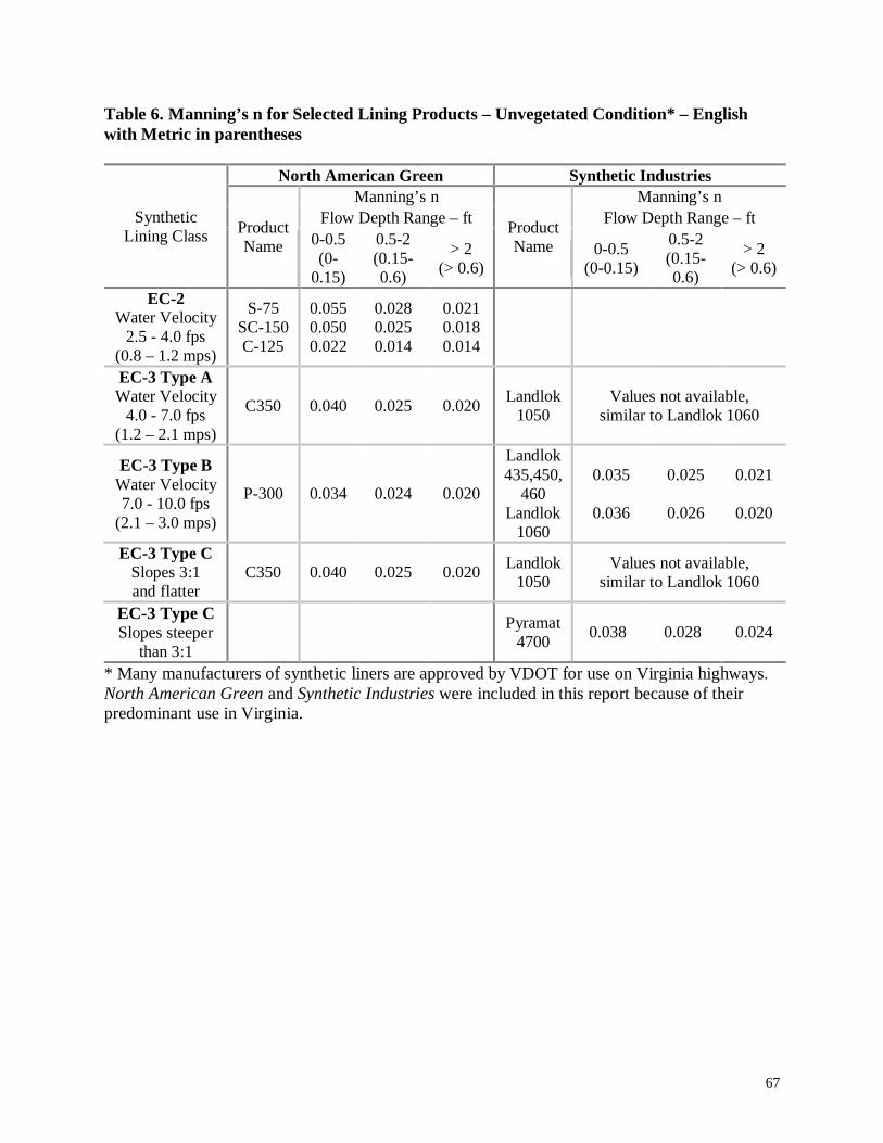
67
Table 6. Manning’s n for Selected Lining Products – Unvegetated Condition* – Englishwith Metric in parentheses
North American Green Synthetic IndustriesManning’s n Manning’s n
Flow Depth Range – ft Flow Depth Range – ftSyntheticLining Class Product
Name 0-0.5(0-
0.15)
0.5-2(0.15-0.6)
> 2(> 0.6)
ProductName 0-0.5
(0-0.15)
0.5-2(0.15-0.6)
> 2(> 0.6)
EC-2Water Velocity
2.5 - 4.0 fps(0.8 – 1.2 mps)
S-75SC-150C-125
0.0550.0500.022
0.0280.0250.014
0.0210.0180.014
EC-3 Type AWater Velocity
4.0 - 7.0 fps(1.2 – 2.1 mps)
C350 0.040 0.025 0.020Landlok
1050Values not available,
similar to Landlok 1060
EC-3 Type BWater Velocity7.0 - 10.0 fps
(2.1 – 3.0 mps)
P-300 0.034 0.024 0.020
Landlok435,450,
460Landlok
1060
0.035
0.036
0.025
0.026
0.021
0.020
EC-3 Type CSlopes 3:1and flatter
C350 0.040 0.025 0.020Landlok
1050Values not available,
similar to Landlok 1060
EC-3 Type CSlopes steeper
than 3:1
Pyramat4700
0.038 0.028 0.024
* Many manufacturers of synthetic liners are approved by VDOT for use on Virginia highways.North American Green and Synthetic Industries were included in this report because of theirpredominant use in Virginia.
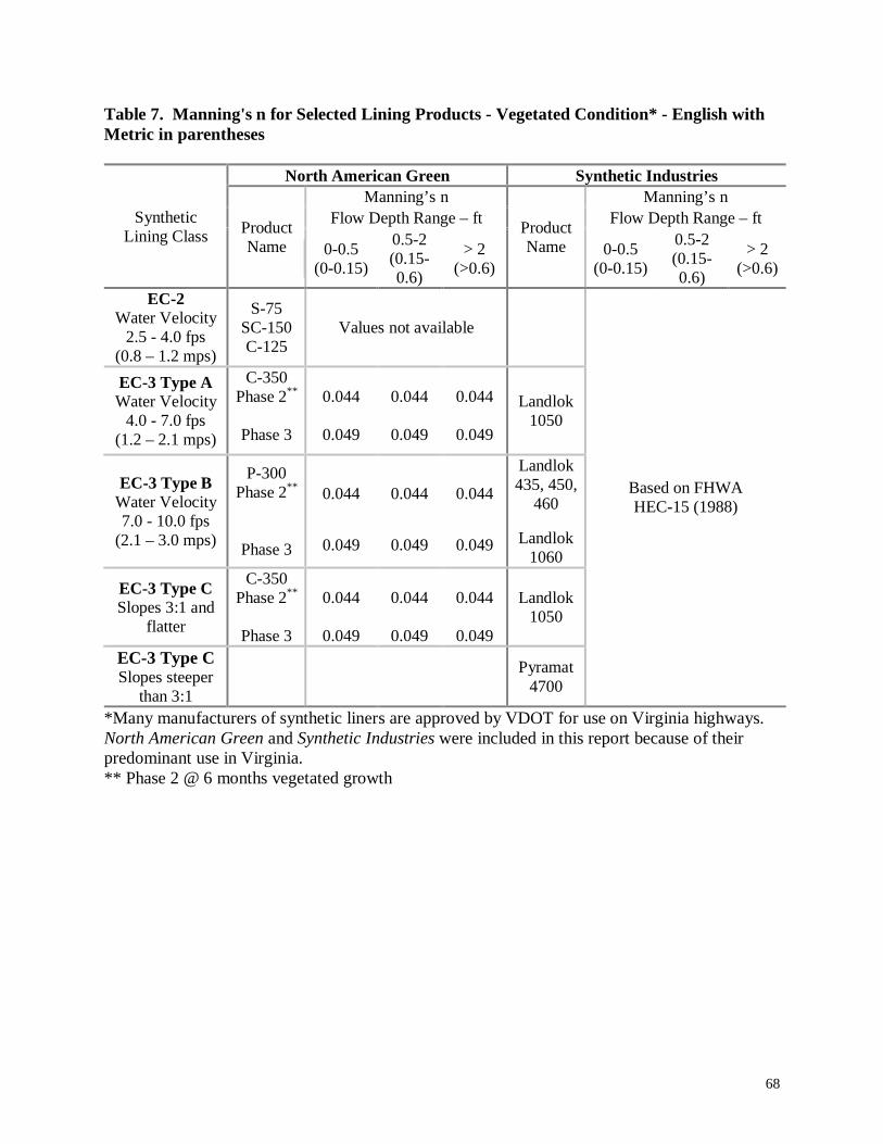
68
Table 7. Manning's n for Selected Lining Products - Vegetated Condition* - English withMetric in parentheses
North American Green Synthetic IndustriesManning’s n Manning’s n
Flow Depth Range – ft Flow Depth Range – ftSyntheticLining Class Product
Name 0-0.5(0-0.15)
0.5-2(0.15-0.6)
> 2(>0.6)
ProductName 0-0.5
(0-0.15)
0.5-2(0.15-0.6)
> 2(>0.6)
EC-2Water Velocity
2.5 - 4.0 fps(0.8 – 1.2 mps)
S-75SC-150C-125
Values not available
EC-3 Type AWater Velocity
4.0 - 7.0 fps(1.2 – 2.1 mps)
C-350Phase 2**
Phase 3
0.044
0.049
0.044
0.049
0.044
0.049
Landlok1050
EC-3 Type BWater Velocity7.0 - 10.0 fps
(2.1 – 3.0 mps)
P-300Phase 2**
Phase 3
0.044
0.049
0.044
0.049
0.044
0.049
Landlok435, 450,
460
Landlok1060
EC-3 Type CSlopes 3:1 and
flatter
C-350Phase 2**
Phase 3
0.044
0.049
0.044
0.049
0.044
0.049
Landlok1050
EC-3 Type CSlopes steeper
than 3:1
Pyramat4700
Based on FHWAHEC-15 (1988)
*Many manufacturers of synthetic liners are approved by VDOT for use on Virginia highways.North American Green and Synthetic Industries were included in this report because of theirpredominant use in Virginia.** Phase 2 @ 6 months vegetated growth
69
Tractive Force Method
The other method currently used by some states to define ditch stability is based on the
maximum tractive force that can be applied by the flowing water on the ditch boundary
(Equation 7).
Should the maximum applied tractive force exceed the forces resisting movement of the soil,
erosion will occur. When very fine grain particles are evaluated (e.g., clay particles), particle
interactions such as cohesiveness will also need to be considered. The designer should be
knowledgeable of theories and principles applied using the tractive force design method to insure
accurate results.
5.4 Discussion5.4.1 Hydraulic Roughness CoefficientsThe current practice recommended by the Virginia Department of Transportation for selection of
hydraulic roughness coefficients is to apply a single value of Manning’s n for each lining
condition. The recommended n value for bare earth condition in Virginia is 0.03, for lined
(synthetic or fully vegetated) ditches a value of 0.05, and for paved ditches a value of 0.015. The
current method of design in Virginia is straightforward and easily applied by design engineers.
However, the values of Manning’s n are applied independent of hydraulic roughness variables
(such as soil type, flow depth, vegetation type).
Results of this research show that many parameters influence hydraulic roughness. For the bare
earth condition, several methods have been proposed in literature on how to best approximate
hydraulic roughness. It appears from the published literature that relating Manning’s n to soil
type is the most effective means of defining hydraulic roughness for a bare soil lining, allowing
flexibility to account for roughness elements of various soils. This approach has been published
in 2 ways: characterizing by a representative particle size and by USDA soil type. Many
researchers have related a statistical particle diameter to hydraulic roughness. The formula
published by Meyer-Peter and Muller (See Table 4) can be valuable in relating Manning’s n and
particle diameter (D90) for nonuniform sediments. The results generated by this approach are not
valid for shallow flows where hydraulic roughness changes significantly with flow depth. Also,
roughness coefficients have been published for soil types listed in the Maximum Allowable
70
Velocity table by Fortier and Scobey (Richardson, et. al., 1990). Both approaches, unlike current
VDOT practice, recognize the variability of hydraulic roughness associated with different soil
types.
The roughness coefficients published in the Maximum Allowable Velocity table by Fortier and
Scobey (Richardson, et. al., 1990) and the equation developed by Meyer-Peter and Muller (1948)
were both used to develop Manning’s n as a function of soil type, see Table 8. This table reflects
an attempt to correlate AASHTO soil descriptions to the USDA descriptions used by Fortier and
Scobey.
Of the methods to characterize Manning’s n for vegetated (grass) linings presented here, the
most effective method appears to be the approach outlined in FHWA HEC-15 (1988) and
presented in Table 5. This calculation procedure captures the effects of species variation, height
of vegetation, slope and hydraulic radius that each influence hydraulic roughness. The current
VDOT practice is to apply a single hydraulic roughness coefficient of 0.05 to all design project
calculations involving vegetal lining in roadside ditches, despite variability that may be present.
Values of Manning’s n published by manufacturers of synthetic linings will be the most accurate
for use in designing roadway ditches with geosynthetics. In Virginia, synthetic linings are
divided into three main classes (EC-2; EC-3A; and EC-3B) based on strength. Information
concerning Manning’s n for individual products should be obtained directly from the
manufacturer. Data from two manufacturers of synthetic linings (North American Greene and
Synthetic Industries) indicates that shallow flow depths can have significant influence on
hydraulic roughness. For flow depths of 0.15m to 0.6m (0.5 ft – 2 ft), a typical depth range for
roadway ditches, an average hydraulic roughness coefficient, taken independent of liner strength
classes assigned by Virginia, for these two manufacturers is 0.024. Because the designer assigns
a liner class rather than a specific brand of liner, it is important for the designer to be able to best
approximate a hydraulic roughness coefficient for the class of lining specified. Collecting
hydraulic roughness coefficients from all manufacturer products approved in Virginia can best
facilitate this need.
71
5.4.2 Stability Criteria
From this research, it was found that currently two methods of determining stability of roadside
drainage ditches are widely used – Maximum Allowable Velocity and Tractive Force. In
Virginia, the Tractive Force Method is used mainly for design of riprap-lined ditches, and not for
stability analysis of unlined ditches. This method, if used correctly, can provide good results for
engineers designing unlined roadside drainage ditches. However, use of the Tractive Force
Method employed in the FHWA computer program HYDRAIN-HYCHL is presently accurate
only for coarser particles. Caution should be used when applying the program to design ditches
lined with fine-grained soils.
Design of roadway drainage ditches in Virginia is performed using the Maximum Allowable
Velocity Method stability criteria, where the expected velocity for the 2-year storm is calculated
– typically for each 100 ft reach of ditch – and compared to the maximum allowable listed for the
soil lining (Table 1). This method has been used and validated for various soil types and
conditions from field experience over many years. However, some difficulties have been
encountered by VDOT hydraulic engineers in implementing this stability criterion.
The USDA Textural descriptions used in Table 3 do not describe soils as specifically as
AASHTO classifications. Textural descriptions are open to interpretation as to which type of
soil actually exists on site; they often widely overlap the more specific AASHTO classifications.
This can lead to confusion about which maximum allowable velocity value to use.
In meetings with personnel from the nine VDOT Construction Districts it appeared that while
there is a standardized methodology throughout Virginia, there is often some confusion about the
classification of soil, and hence which maximum allowable velocity from Table 3 should be
used. While soils information is available from VDOT Materials Section reports, it is often not
available at the time when roadside ditch design is taking place. Consequently, ditches often are
designed without the use of this important piece of information.
Although mandated for use by VDOT, the AASHTO classification system is not consistently
used for classification of soils in roadside ditch design. When AASHTO soil classifications were
72
checked against USDA Textural soil descriptions, it became clear that accurate correlations
between the two systems could not be made. Consequently, the effectiveness of the maximum
allowable velocity table is minimized when soil reports using AASHTO classifications are
distributed.
An effort was made to update Table 3 (Table 2.8.1 in the Virginia Drainage Manual) by cross-
checking USDA Textural soil descriptions with AASHTO soil classifications (Table 8).
Maximum water velocities used in Virginia were checked against values used in nearby states
and against the average of values used in Virginia. In most cases, after determining the ASHTO
classification, it was found that the presently used maximum velocities associated with different
soil types were on the conservative side, and new maximum velocities were established.
These values can be considered as reasonable guidelines for the present. Research into the
erodibility of these soils will provide more definitive values of maximum water velocity
tolerated by each soil type.
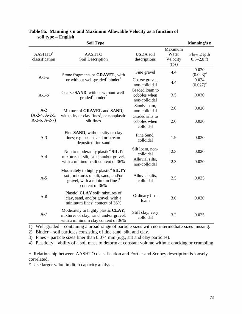
73
Table 8a. Manning’s n and Maximum Allowable Velocity as a function ofsoil type – English
Soil Type Manning’s n
AASHTO+
classificationAASHTO
Soil DescriptionUSDA soildescriptions
MaximumWater
Velocity(fps)
Flow Depth0.5–2.0 ft
Fine gravel 4.40.020
(0.023)#A-1-a
Stone fragments or GRAVEL , withor without well-graded1 binder2 Coarse gravel,
non-colloidal4.4
0.024(0.027)#
A-1-bCoarse SAND, with or without well-
graded1 binder2Graded loam tocobbles whennon-colloidal
3.5 0.030
Sandy loam,non-colloidal
2.0 0.020A-2(A-2-4, A-2-5,A-2-6, A-2-7)
Mixture of GRAVEL and SAND,with silty or clay fines3, or nonplastic
silt finesGraded silts tocobbles when
colloidal2.0 0.030
A-3Fine SAND, without silty or clayfines; e.g. beach sand or stream-
deposited fine sand
Fine Sand,colloidal
1.9 0.020
Silt loam, non-colloidal
2.3 0.020A-4
Non to moderately plastic4 SILT ;mixtures of silt, sand, and/or gravel,with a minimum silt content of 36% Alluvial silts,
non-colloidal2.3 0.020
A-5
Moderately to highly plastic4 SILTYsoil; mixtures of silt, sand, and/or
gravel, with a minimum fines3
content of 36%
Alluvial silts,colloidal
2.5 0.025
A-6Plastic4 CLAY soil; mixtures ofclay, sand, and/or gravel, with aminimum fines3 content of 36%
Ordinary firmloam
3.0 0.020
A-7Moderately to highly plastic CLAY ;mixtures of clay, sand, and/or gravel,with a minimum clay content of 36%
Stiff clay, verycolloidal
3.2 0.025
1) Well-graded – containing a broad range of particle sizes with no intermediate sizes missing.2) Binder – soil particles consisting of fine sand, silt, and clay.3) Fines – particle sizes finer than 0.074 mm (e.g., silt and clay particles).4) Plasticity – ability of a soil mass to deform at constant volume without cracking or crumbling.
+ Relationship between AASHTO classification and Fortier and Scobey description is looselycorrelated.# Use larger value in ditch capacity analysis.
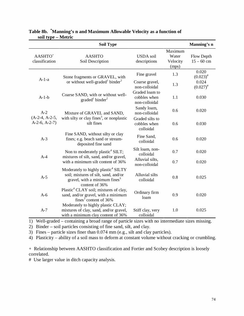
74
Table 8b. *Manning’s n and Maximum Allowable Velocity as a function ofsoil type – Metric
Soil Type Manning’s n
AASHTO+
classificationAASHTO
Soil DescriptionUSDA soildescriptions
MaximumWater
Velocity(mps)
Flow Depth15 – 60 cm
Fine gravel 1.30.020
(0.023)#A-1-a
Stone fragments or GRAVEL, withor without well-graded1 binder2 Coarse gravel,
non-colloidal1.3
0.024(0.027)#
A-1-bCoarse SAND, with or without well-
graded1 binder2Graded loam tocobbles whennon-colloidal
1.1 0.030
Sandy loam,non-colloidal
0.6 0.020A-2(A-2-4, A-2-5,A-2-6, A-2-7)
Mixture of GRAVEL and SAND,with silty or clay fines3, or nonplastic
silt finesGraded silts tocobbles when
colloidal0.6 0.030
A-3Fine SAND, without silty or clayfines; e.g. beach sand or stream-
deposited fine sand
Fine Sand,colloidal
0.6 0.020
Silt loam, non-colloidal
0.7 0.020A-4
Non to moderately plastic4 SILT;mixtures of silt, sand, and/or gravel,with a minimum silt content of 36% Alluvial silts,
non-colloidal0.7 0.020
A-5
Moderately to highly plastic4 SILTYsoil; mixtures of silt, sand, and/or
gravel, with a minimum fines3
content of 36%
Alluvial siltscolloidal
0.8 0.025
A-6Plastic4 CLAY soil; mixtures of clay,sand, and/or gravel, with a minimum
fines3 content of 36%
Ordinary firmloam
0.9 0.020
A-7Moderately to highly plastic CLAY;mixtures of clay, sand, and/or gravel,with a minimum clay content of 36%
Stiff clay, verycolloidal
1.0 0.025
1) Well-graded – containing a broad range of particle sizes with no intermediate sizes missing.2) Binder – soil particles consisting of fine sand, silt, and clay.3) Fines – particle sizes finer than 0.074 mm (e.g., silt and clay particles).4) Plasticity – ability of a soil mass to deform at constant volume without cracking or crumbling.
+ Relationship between AASHTO classification and Fortier and Scobey description is looselycorrelated.# Use larger value in ditch capacity analysis.

75
CHAPTER 6. CONCLUSIONS
From the presented data, it can be concluded that several factors may be contributing to the poor
performance of roadside ditches in some regions of the state, while in other parts of the state
over-design may be occurring. These factors can be categorized into three major topics. One,
from information presented by VDOT personnel it appears that design of roadside ditches relies
heavily on default design criteria, and these default criteria are applied independent of site
locations and soil conditions. Two, there is a present lack of actual field soils data, useful in the
design of roadside ditches, that is collected and made available to hydraulic designers. Three,
other factors include geographical and management issues which current VDOT policy and
procedures do not explicitly manage.
From information gathered from VDOT hydraulic engineers, it can be concluded that several
issues may be contributing to poor design of ditches. The loose application, and often incorrect
use, of the Rational Method results in inaccurate determination of peak flow of design storms.
Current use of default Manning’s n values used for each lining condition does not allow the
designer to account for site variability. The present lack of actual field soils data often results in
the use of default maximum allowable velocity for unlined ditches. These criteria are applied
consistently on all projects and independent of site variability. Collectively, these factors could
result in some instances in the poor performance of roadside ditches, while in other instances
they could result in overly conservative designs.
It was learned from discussions with VDOT personnel at each district that practices for the
collection and use of soil/rock data vary widely across the state and often consist of the minimum
recommended practice, or less. The current minimum recommended soils collection practice as
defined in the Manual of Instructions (1995) supplies the hydraulic ditch designer with minimal
soils data necessary for ditch design. When practiced, the minimal soils collection practice
provides borings spaced more than three times the ditch design reach length. Often, the
hydraulic engineer receives a copy of the soils report, if at all, only after substantial completion
of ditch design. Consequently, insufficient soils data collection and untimely distribution, if at
all, results in ditches being designed without the site specific information.

76
Finally, certain geographical and management issues not currently incorporated in VDOT
procedures influence the performance of roadside ditches. These factors include certain
geographical features (degrading rock conditions, steep slopes, and tidal fluctuations),
enforcement of stormwater management, construction contract provisions, acquisition of
roadway right-of-way, and District participation in Central Office and consultant project designs.
These factors possibly contribute to the poor performance of roadside ditches.
77
CHAPTER 7. RECOMMENDATIONS
Several methods have been used to collect available information related to the design of roadside
ditches. Reference material released by Virginia DOT were surveyed to learn the current
established policy and procedures for soil data collection and reporting, and the design practice
for hydrological and hydraulic analyses of roadside ditches. Site visits to each of Virginia’s nine
construction districts were made to interview District personnel about their personal experience
with roadside ditch design, performance, and erosion failures. Current ditch design practices in
nine states were investigated through the collection state drainage manuals and interviews with
DOT personnel. A site visit to the Mount Airy District of the North Carolina Department of
Transportation was made with the intent of learning NCDOT design and construction procedures
for roadside ditches and to learn how problematic soils, found in their state which are similar in
composition to soils found in Virginia, are managed. An extensive review of current literature
was performed with the intent of investigating current research on topics related to ditch design
and erosion control.
Information collected by these processes have been analyzed and recommendations have been
drawn. The recommendations are presented below in four major categories: Collection and
Reporting of Soil/Rock Data; Hydrologic and Hydraulic Analyses; Management Issues; and
Future Research.
Collection and Reporting of Soil /Rock Data
Utilizing soil/rock data collected in the field is important in capturing the effects of site
variability in the hydraulic design of roadside ditches. Site variability becomes visible through
two primary features in the hydraulic design of ditches. These features are hydraulic roughness
coefficient and stability criteria. Both parameters of hydraulic design rely on soil type.
Consequently, accurate identification of soil type comprising the ditch line is key in the selection
of Manning’s n and the application of appropriate stability criteria.
The Materials Division of VDOT is responsible for the collection of soil/rock data. The current
objective of the geotechnical investigation, described in the Manual of Instructions, is “to acquire
data for the design of roadway foundations cut and fill slopes, soil stabilization and retaining
78
systems, and structure foundations” (1995). It is recommended to include roadside ditch design
to the objective of geotechnical investigations.
From VDOT personnel it was learned that the minimum geotechnical investigation as outlined in
the Manual of Instructions (1995) is observed, and often less is practiced. Current minimum
soil/rock collection procedures as defined in the Manual of Instructions (1995) specify to have
borings for suitable soils spaced at 100 m, more than three times the length of the roadside ditch
design reach. To provide more substantial soils data to the hydraulic engineer, it is
recommended that boring spacing be decreased. By increasing the boring frequency, the length
between borings will be smaller allowing for better interpolation of soil type between borings.
From VDOT personnel it was learned that current sampling procedures vary widely across the
state and, in many instances, unrepresentative samples are being collected. It is recommended
that the Materials Division review the procedures for minimum geotechnical investigation as
outlined in the Manual of Instructions (1995) and that proper sampling procedures as outlined in
AASHTO T 86 (AASHTO, 1990) be observed. Following this recommendation, uniformity of
sampling procedures can be achieved across the state in the control and use of materials
information.
In general, the primary reason, indicated by surveyed VDOT personnel, that actual field
conditions are not used in the design of drainage ditches is due to late distribution, if at all, of the
final soil survey to the hydraulic engineers. It is recommended that VDOT develop a timeline
for the distribution of the soils report to the Location and Design Division which accommodates
the need for hydraulic engineers to gain access to pertinent field data for the design of roadside
ditches prior to the completion of substantial ditch design.
Hydrologic and Hydraulic Analyses
From surveyed VDOT personnel, it was learned that several factors may be contributing to the
poor design of ditches. Current hydraulic design of roadside ditches often relies heavily on the
application of default design criteria. Default design criteria were indicated to be used in all
79
aspects of the hydraulic design, including hydrologic, hydraulic, and stability analyses. The
application of default design criteria diminishes the influence of site variability in design.
The design of roadside ditches begins with the determination of peak flow of the ditch for the
selected design storm. From surveyed VDOT personnel, it was learned that the Rational Method
is often used for peak flow determination. However, from these discussions it was learned that
the Rational Method is often loosely and inappropriately applied. It is recommended that VDOT
hydraulic engineers review the limitations and proper application procedures of the Rational
Method. As revealed by surveyed VDOT personnel, areas of concentration include proper
determination of time of concentration, delineation of actual drainage area, and appropriately
accounting for various land uses located within the drainage area.
It was learned from VDOT personnel that freeboard intent varies widely across the state, and in
some cases is not accounted for at all. To provide a safety factor for the capacity of the ditch, it
is recommended that designs accommodate at least 6 inches of freeboard.
In an effort to account for site variability in the design of roadside ditches, field data needs to be
incorporated into design. Because the hydraulic roughness coefficients and stability criteria are
the two primary parameters in ditch design which account for site variability, they have become
the focus in addressing this issue.
Using current available research, tables have been prepared which account for variability of
Manning’s n for bare earth lining and vegetated linings. The values of Manning’s n presented in
Table 8 were developed from the use of the Meyer-Peter and Muller equation and information
presented in the FHWA publication Highways in the River Environment (1990). These values,
based on soil type, are recommended for use in the hydraulic analysis of unlined (bare earth)
ditches. Stability analysis of roadway ditches is dependent on the accurate selection of hydraulic
roughness coefficients.
The selection of hydraulic roughness coefficient for vegetated linings can have significant affects
on the determination of ditch capacity. Table 5, taken from FHWA HEC-15 (1988), presents
80
equations that can be used to calculate Manning’s n for vegetated linings. This approach
accounts for variability that is present in vegetated linings. These equations are recommended
for use in capacity analysis of roadway ditches.
VDOT officials requested that a review of hydraulic roughness coefficients of synthetic linings
for each of Virginia’s three Erosion Control (EC) classes be performed. Although numerous
manufacturers of synthetic lining products exist and are approved for use in Virginia, only two
manufacturers (North American Greene and Synthetic Industries) were selected to be included in
this review for illustration purposes and because of their widespread use on Virginia highways.
This information has been collected from these manufacturers and summarized. Table 6 presents
hydraulic roughness coefficients for the unvegetated state. Table 7 presents hydraulic roughness
coefficients for these products in the vegetated condition. From the data collected in this research
an average value of hydraulic roughness coefficient, taken independent of lining strength, for the
unvegetated condition is 0.024. Because the manufacturer of synthetic lining is not known
during design of roadside ditches, it is useful for the designer to have an approximate,
representative value of hydraulic roughness. To accommodate this need, it is recommended that
an extensive review of hydraulic roughness coefficients of synthetic linings be performed.
As indicated by surveyed VDOT personnel, default maximum allowable velocities are used in
stability analysis often because pertinent soils information is not available to them during design.
Following a previous recommendation to develop a timeline for the distribution of the final soil
report to the Location and Design Division, field soils data will be made available to hydraulic
designers prior to substantial completion of ditch design.
The current determination of stability recommended in Virginia is to use the Fortier and Scobey
Maximum Allowable Velocity chart, Table 3 in this thesis. The current table forms a
relationship between USDA soil descriptions and corresponding maximum allowable velocities.
This table, using USDA soil descriptions, is not consistent with the Virginia mandate for the use
of AASHTO classification of soils in roadside ditch design. An effort was made to update Table
3 by cross-checking USDA Textural soil descriptions with AASHTO soil classifications. Using
maximum allowable velocity criteria used in other states, new maximum velocities were
81
established and are presented in Table 8. This table, based on current available data, is
recommended for use in Virginia for stability analysis of unlined ditches.
Management Issues
Several management issues were highlighted by VDOT personnel which may be contributing to
the poor performance of ditch design. The factors include enforcement of stormwater
management regulations on private developments, acquisition of roadway right-of-way,
construction contract provisions, and District participation in Central Office and consultant
project designs.
Virginia stormwater management regulations need to be adequately enforced on private
developments. To accommodate this need, additional personnel may be necessary. This
recommendation is based on the serious concern expressed by VDOT officials of private
developments increasing the flow in ditch lines, often exceeding the design flow resulting in
failure of the structure either through excessive erosion or excessive deposition downstream.
Acquisition of adequate roadway right-of-way should be obtained to accommodate required side
slopes for ditch stability. This recommendation refers both to the development of new roads as
well as to the upgrade of existing road structures.
Many VDOT personnel have expressed concern over the task-based approach used in Virginia
construction contracts for seeding requirements. This task-based approach to seeding has
resulted in many instances in the lack of vegetation on the site when the contractor has fulfilled
her/his obligations of the contract. The establishment of vegetation in these instances becomes
the responsibility and expense of VDOT. Based on the success the North Carolina Department
of Transportation has had with performance-based construction contracts and seeding incentives,
Virginia may want to explore the use of similar contract language. Also, the contract clause for
“Response for Erosion Control” has been successful in aiding NCDOT in the establishment of
vegetation before contractors are released from the contract and leave the construction site.

82
VDOT personnel also indicated interest in becoming more involved in Central Office and
consultant designs. Allowing local personnel to become more involved in Central Office and
consultant designs will allow District personnel to share their knowledge of local conditions and
will decrease the number of field modifications needed during construction of ditches. These
modifications often involve adjustments necessary to accommodate unique erosion control issues
based on local conditions. Increased District involvement can reduce the time and expense
associated with field modifications under these circumstances.
Future Research
As discussed in Chapter 5, the relationship between soil type and maximum allowable velocity
currently used in Virginia is based on the pioneer work of Fortier and Scobey (1926). As part of
this research, an attempt was made to correlate the USDA soil descriptions used by Fortier and
Scobey to AASHTO soil classifications currently mandated by Virginia. When AASHTO soil
classifications were checked against USDA Textural soil descriptions, it became clear that
accurate correlations between the two systems could not be made. To establish a more sound
relationship between AASHTO soil classifications and maximum allowable velocity, research
was done to investigate maximum allowable velocity stability criteria currently used in other
states. The recommended relationship for maximum allowable velocity and AASHTO soil
classifications described in Table 8 represents the best recommended maximum velocity stability
criteria based on current available information. Future research should refine/adjust this
relationship.
To better account for variation in Manning’s n for bare earth lined ditches, a relationship
between soil type and hydraulic roughness has been developed in Table 8. This relationship was
developed using a version of Fortier and Scobey’s maximum allowable velocity table describing
hydraulic roughness as a function of USDA soil descriptions published in Richardson et. al
(1990), and using the Meyer-Peter and Muller equation (see Table 4). It is recommended that
future research be used to establish a more definitive relationship between AASHTO soil
descriptions and hydraulic roughness coefficients.
83
As presented in this research, Manning’s n is known to be dependent on many variables,
including grain size, flow depth, etc. Extensive research has been done to characterize hydraulic
roughness coefficients by various parameters. However, little research has been done to
investigate the influence channel shape has, if any, on hydraulic roughness coefficients of small
channel cross-sections. Future research could explore how channel shape influences Manning’s
n (of any lining condition) of small channel cross-sections.
The Tractive Force Method, based on scientific principles and presented in the FHWA
publication HEC-15 (1988), is used mainly for design of rip rap lined ditches in Virginia. This is
a more recently developed design theory, and represents the interaction between flowing water
and its boundary more closely. However, use of the Tractive Force Method employed in the
FHWA computer program HYDRAIN-HYCHL is presently accurate only for coarser particles.
Future research could better define stability criteria for finer grained particles.
84
CHAPTER 8. APPLICATION
From discussions with VDOT roadside ditch designers, it was discovered that design practice
varies considerably across Virginia. To achieve uniformity in the design process of roadside
ditches, a detailed formulation the calculation procedure has been developed. The procedure
described below, based on the current recommended procedure in the Virginia Drainage Manual
(1989), incorporates the recommended tools for design presented in this research. Because the
Rational Method is typically applicable to roadside ditch design, the outlined procedure is geared
for the use of this method. The designer should ensure that the use of the Rational Method is
appropriate for the ditch drainage area.
1. The ditch under investigation is divided into design reaches corresponding to segments of
length, usually 100 ft (30m). The drainage area(s) of each design segment is delineated.
Topographic maps, or other resources, should be consulted to accurately determine the
drainage area of each design reach.
2. Determine the average longitudinal slope for the ditch design reach under consideration.
3. Peak flow for the intended design storm is then calculated, typically using the Rational
Method. If the use of the Rational Method is not appropriate, another method should be used
to calculate peak flow, such as Snyder’s Method.
4. When the use of the Rational Method is appropriate (see Chapter 4), runoff coefficient(s) can
then be determined for the first reach. The first reach corresponds to the highest design reach
by elevation. The designer should assess land uses by consulting recent aerial photographs
of the design area, or by visual inspection.
5. Time of concentration to the downstream end of the first ditch design reach is determined
using Figure 1.5.1.2 of the Virginia Drainage Manual (1989).
6. Using the appropriate Intensity-Duration-Frequency (IDF) curve, time of concentration, and
a 10-year storm curve, determine the 10-year rainfall intensity. IDF curves are available for
all Virginia counties in the Virginia Drainage Manual (1989). Using the 10-year rainfall
intensity, determine the 10-year discharge, Q10.
7. The depth of flow in the ditch for the 10-year storm should be determined, based on the type
of permanent lining utilized, to insure that the capacity of the ditch has not been exceeded.
85
Grass lining is the preferred permanent lining. Table 5 presents equations based on vegetal
retardance class for the determination of Manning’s n for vegetated linings. Table 7 presents
values of Manning’s n for the vegetated state of various products of two manufacturers
products approved for use on Virginia highways. The appropriate value of Manning’s n
should be used when calculating the 10-year storm depth.
8. To allow for freeboard, 6 inches should be added to the calculated 10-year storm depth in
Step 7.
9. Using Table 8, determine the maximum allowable velocity and Manning’s n for the soil type
comprising the unlined ditch. The classification of the soil comprising the ditch lining is
ideally determined in the field.
10. Determine the 2-year storm peak flow, Q2 (see Steps 3-6).
11. Using Manning’s equation (Equation 3) with the hydraulic roughness coefficient found in
Step 9 for the unlined ditch, the Continuity Equation (Equation 4), and the 2-year storm flow
determined in Step 10, determine the 2-year velocity for the selected ditch cross-section.
12. Compare the calculated 2-year storm velocity against the maximum allowable velocity of the
soil comprising the ditch lining found in Step 9. If the calculated 2-year storm velocity
exceeds the maximum allowable velocity, some level of erosion protection is needed, or
revisions should be made to channel cross-section or ditch grade and Steps 7 and 8 repeated.
If the computed velocity is less than the allowable velocity, no protection is required.
If some level of erosion protection is needed, the designer should select a class of temporary
lining, as established by Virginia. Table 6 contains Manning’s n values for temporary
synthetic lining products of two manufacturers approved for use on Virginia highways. A
list of all approved products can be obtained from VDOT. Manning’s n values can be
obtained for all synthetic lining products produced by a selected manufacturer, and should be
used in design.
Using Q2 found in Step 10 and the appropriate hydraulic roughness coefficient for the
selected class of temporary lining, determine the 2-year storm velocity. If this calculated 2-
year storm exceeds the maximum allowable velocity for the selected lining class, then a
stronger lining is required. Repeat this procedure until stability of a selected lining is
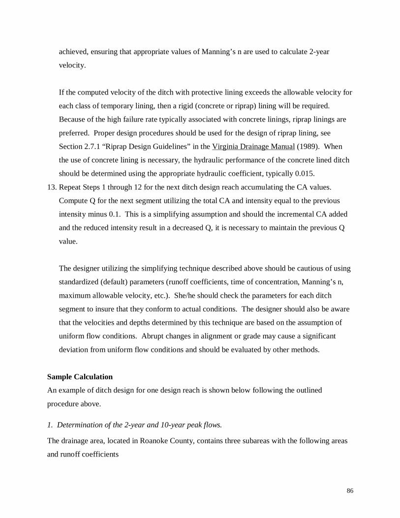
86
achieved, ensuring that appropriate values of Manning’s n are used to calculate 2-year
velocity.
If the computed velocity of the ditch with protective lining exceeds the allowable velocity for
each class of temporary lining, then a rigid (concrete or riprap) lining will be required.
Because of the high failure rate typically associated with concrete linings, riprap linings are
preferred. Proper design procedures should be used for the design of riprap lining, see
Section 2.7.1 “Riprap Design Guidelines” in the Virginia Drainage Manual (1989). When
the use of concrete lining is necessary, the hydraulic performance of the concrete lined ditch
should be determined using the appropriate hydraulic coefficient, typically 0.015.
13. Repeat Steps 1 through 12 for the next ditch design reach accumulating the CA values.
Compute Q for the next segment utilizing the total CA and intensity equal to the previous
intensity minus 0.1. This is a simplifying assumption and should the incremental CA added
and the reduced intensity result in a decreased Q, it is necessary to maintain the previous Q
value.
The designer utilizing the simplifying technique described above should be cautious of using
standardized (default) parameters (runoff coefficients, time of concentration, Manning’s n,
maximum allowable velocity, etc.). She/he should check the parameters for each ditch
segment to insure that they conform to actual conditions. The designer should also be aware
that the velocities and depths determined by this technique are based on the assumption of
uniform flow conditions. Abrupt changes in alignment or grade may cause a significant
deviation from uniform flow conditions and should be evaluated by other methods.
Sample Calculation
An example of ditch design for one design reach is shown below following the outlined
procedure above.
1. Determination of the 2-year and 10-year peak flows.
The drainage area, located in Roanoke County, contains three subareas with the following areas
and runoff coefficients
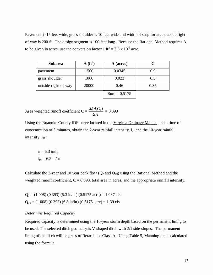
87
Pavement is 15 feet wide, grass shoulder is 10 feet wide and width of strip for area outside right-
of-way is 200 ft. The design segment is 100 feet long. Because the Rational Method requires A
to be given in acres, use the conversion factor 1 ft2 = 2.3 x 10⁻⁵ acre.
Subarea A (ft2) A (acres) C
pavement 1500 0.0345 0.9
grass shoulder 1000 0.023 0.5
outside right-of-way 20000 0.46 0.35
Sum = 0.5175
Area weighted runoff coefficient C = i
ii
A
CA
ΣΣ )(
= 0.393
Using the Roanoke County IDF curve located in the Virginia Drainage Manual and a time of
concentration of 5 minutes, obtain the 2-year rainfall intensity, i2, and the 10-year rainfall
intensity, i10:
i2 = 5.3 in/hr
i10 = 6.8 in/hr
Calculate the 2-year and 10 year peak flow (Q2 and Q10) using the Rational Method and the
weighted runoff coefficient, C = 0.393, total area in acres, and the appropriate rainfall intensity.
Q2 = (1.008) (0.393) (5.3 in/hr) (0.5175 acre) = 1.087 cfs
Q10 = (1.008) (0.393) (6.8 in/hr) (0.5175 acre) = 1.39 cfs
Determine Required Capacity
Required capacity is determined using the 10-year storm depth based on the permanent lining to
be used. The selected ditch geometry is V-shaped ditch with 2:1 side-slopes. The permanent
lining of the ditch will be grass of Retardance Class A. Using Table 5, Manning’s n is calculated
using the formula:
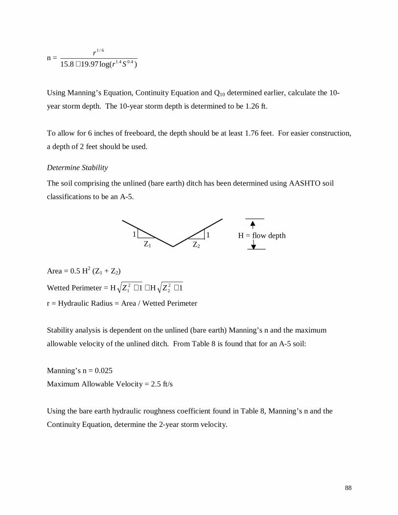
88
n = )log(97.198.15 4.04.1
6/1
Sr
r
+
Using Manning’s Equation, Continuity Equation and Q10 determined earlier, calculate the 10-
year storm depth. The 10-year storm depth is determined to be 1.26 ft.
To allow for 6 inches of freeboard, the depth should be at least 1.76 feet. For easier construction,
a depth of 2 feet should be used.
Determine Stability
The soil comprising the unlined (bare earth) ditch has been determined using AASHTO soil
classifications to be an A-5.
Area = 0.5 H2 (Z1 + Z2)
Wetted Perimeter = H ++ 121Z H 12
2 +Z
r = Hydraulic Radius = Area / Wetted Perimeter
Stability analysis is dependent on the unlined (bare earth) Manning’s n and the maximum
allowable velocity of the unlined ditch. From Table 8 is found that for an A-5 soil:
Manning’s n = 0.025
Maximum Allowable Velocity = 2.5 ft/s
Using the bare earth hydraulic roughness coefficient found in Table 8, Manning’s n and the
Continuity Equation, determine the 2-year storm velocity.
H = flow depthZ2
11Z1
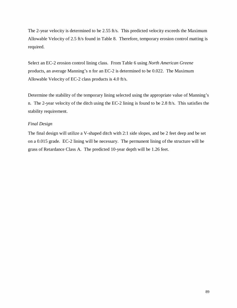
89
The 2-year velocity is determined to be 2.55 ft/s. This predicted velocity exceeds the Maximum
Allowable Velocity of 2.5 ft/s found in Table 8. Therefore, temporary erosion control matting is
required.
Select an EC-2 erosion control lining class. From Table 6 using North American Greene
products, an average Manning’s n for an EC-2 is determined to be 0.022. The Maximum
Allowable Velocity of EC-2 class products is 4.0 ft/s.
Determine the stability of the temporary lining selected using the appropriate value of Manning’s
n. The 2-year velocity of the ditch using the EC-2 lining is found to be 2.8 ft/s. This satisfies the
stability requirement.
Final Design
The final design will utilize a V-shaped ditch with 2:1 side slopes, and be 2 feet deep and be set
on a 0.015 grade. EC-2 lining will be necessary. The permanent lining of the structure will be
grass of Retardance Class A. The predicted 10-year depth will be 1.26 feet.
90
REFERENCES
AASHTO (American Association of State Highway and Transportation Officials). HighwayDesign and Operational Practices Related to Highway Safety, AASHTO SelectCommittee on Highway safety, second edition, 1974.
AASHTO, 1990, "Standard Method of Test for Soil Investigation and Sampling by AugerBorings (T 203-82 (1990))", Standard Specifications for Transportation Materials andMethods of Sampling and Testing, 15th ed., Part II Tests
AASHTO. Model Drainage Manual, ISBN I-56051-010-2, 1991.
AASHTO (American Association of State Highway and Transportation Officials). HighwayDrainage Guidelines. 1992.
Arcement, George J., Jr., and Verner. Schneider. Guide for Selecting Manning’s RoughnessCoefficients for Natural Channels and Flood Plains. U.S.G.S Water-Supply Paper 2339,1989.
Bathurst, J.C. “Flow resistance of large-scale roughness”, Journal of the Hydraulics Division,American Society of Civil Engineers, 104, (HY12): pp.1587-1603, 1985.
Bedient, Philip B., Wayne C. Huber. Hydrology and Floodplain Analysis 2nd Edition, Addison-Wesley Publishing Company, 1992.
Benson and Dalrymple, T., “General field and office procedures for indirect dischargemeasurements”, Chapter A1, Book 3, Techniques of Water Resources Investigations of theU.S. Geological Survey, p. 30, 1967.
Brown, S.A., S.M. Stein, J.C. Warner. Urban Drainage Design Manual. Hydraulic EngineeringCircular No. 22. Federal Highway Administration Publication No. FHWA-SA-96-078,November 1996.
Chapuis, R.P., Gatien, T. (1986) "An Improved Rotating Cylinder Technique for QuantitativeMeasurements of the Scour Resistance of Clays", Canadian Geotech. J. 23, 83-87 (1986).
Chow, Ven Te, Open-channel Hydraulics. McGraw-Hill, New York, p. 680, 1959.
Cowan, W.L. “Estimating Hydraulic roughness Coefficients”, Agricultural Engineering. Vol.37, No. 7, pp. 473 – 475, 1956.
Darby, S. E. and Thorne, C. R. “Development and Testing of Riverbank Stability Analysis,”Journal of Hydraulic Engineering, ASCE, Vol. 122 (8), pp. 443-454, 1996.
91
Das, Braja M. Principles of Geotechnical Engineering, Third Edition, PWS PublishingCompany, 1994.
Fortier, S., and Scobey, F. C., “Permissible Canal Velocities,” Transactions of the AmericanSociety of Civil Engineers, vol. 89, 1926, pp. 940 – 984.
French, Richard H. Open Channel Hydraulics. McGraw-Hill, Inc., New York, 1985.
Gray, Donald, and Robbin Sotir. Biotechnical and Soil Bioengineering Slope Stabilization.John Wiley & Sons, Inc: New York, 1996.
Hoffman, G.J., and H.J. Verheij. Scour Manual. Published by A.A. Balkema: Brookfield, VT,pp. 15-22, 1997.
Holtz, Robert D., and William D. Kovacs. An Introduction to Geotechnical Engineering.Published by Prentice Hall, 1981.
Hydraulic Design Series No. 3. Design Charts for Open Channel Flow, Federal HighwayAdministration, U.S. Government Printing Office, 1961.
Hydraulic Design Series No. 4. Design of Roadside Drainage Channels, Federal HighwayAdministration, U.S. Government Printing Office, 1965.
Hydraulic Engineering Circular No. 11, Use of Riprap for Band Protection, Federal HighwayAdministration, 1987.
Hydraulic Engineering Circular No. 15, Design of Roadside Channels with Flexible Linings, byDr. Y.H. Chang, and G.K. Cotton. FHWA Publication No. FHWA-IP-87-7, Prepared forthe U.S. Department of Transportation, Federal Highway Administration, Washington,D.C., April 1988.
Jarrett, R. D. “Hydraulics of high-gradient streams, Journal of Hydraulic Engineering, 110(11):pp. 1519 – 1539, 1984.
Kumapley, N.K. “Erosion of unsurfaced earth and gravel roads”. Soil Mechanics andFoundation Engineering 9th Regional conference for Africa, vol. 1 pp. 397-404, 1987.
Lawler, D.M. (1993) “Needle Ice Processes and Sediment Mobiliztion on River Banks – TheRiver Ilston, West-Glamorgan, UK”, Journal of Hydrology 150: (1) pp. 81-114.
Limerinos, J. T. “Determination of the Manning coefficient from measured bed roughness innatural channels”, U.S. Geological Survey Water-Supply Paper 1898-B, 1970.
Manual of Instructions- Metric version, Materials Division, Virginia Department ofTransportation, 1995.
92
Marcus, W. Andrew, Keith Robers, Leslie Harvey, and Gary Tackman. “An evaluation ofmethods for estimating Manning’s n in small mountain streams”, Mountain Research andDevelopment, vols.12, no. 3, pp. 227 – 239, 1992.
Marek, C.R. "Proposed Standard for Sizes of Stone for Erosion Control", Rock for ErosionControl, ASTM STP 1177, Charles H. McElroy and David A. Lienhart, Eds., AmericanSociety for Testing and Materials, Philadelphia, 1993.
Meyer-Peter, E., and Muller, R., “Formulas for Bed-Load Transport,” Report on Second Meetingof International Association for Hydraulic Research, Stockholm, Sweden, 1948, pp. 39-64.
Morris P. H. Graham, J. and Williams, D. J., “Cracking in Drying Soils,” CanadianGeotechnical Journal, Vol. 29 (2), pp. 263-277, 1992.
New York State Department of Transportation. “Bank and Channel Protective Lining DesignProcedures”, Geotechnical Engineering Bureau, State Campus, Albany, N.Y. 122321995.
Ohu, John O., S.V. Raghavan, E. McKyes, G. Mehuys. “Shear Strength Prediction of CompactedSoils with Varying Added Organic Matter Contents”, Transactions of the AmericanSociety of Agricultural Engineers, Vol. 29(2): March-April 1986, pp. 351-355.
O’Neil, M. P. and McDonnell, J. J., “Effects of Soil-Moisture Dynamics on Slope Failure atHyrum Reservoir, Utah,” Earth Surface Processes and Landforms, Vol. 20 (3), pp. 243-253, 1995.
Richardson, E.V., D.B. Simons, P.Y. Julien. Highways in the River Environment ParticipantNotebook. National Highway Institute Course No. 13010, Federal HighwayAdministration Publication No. FHWA-HI-90-016, February 1990.
Road Design Manual, Location and Design Division, Virginia Department of Transportation,1998.
Strickler. A., “Beitrage zur frage dew geschwindigheits-formel und der rauhigkeiszahlen furstrome, kanale und geschlossene leitungen”, Mitteilungen des eidgenossischer Amtes furWasserwirtschaft. Bern, Switzerland, no. 16, 1923.
Vanoni, Vito. Sedimentation Engineering. Prepared by the ASCE Task Committee for thePreparation of the Manual on Sedimentation of the Sedimentation Committee of theHydraulics Division, New York, NY, 1977.
Virginia Drainage Manual, Prepared by Location and Design Division, Hydraulics Section,Adopted by Virginia Department of Transportation, 1989.
Washington State Department of Transportation, Planning, Research and Public TransportationDivision. Highway Construction Site Erosion and Pollution Control Manual. WA-RD
93
200.2 in cooperation with the United States Department of Transportation FederalHighway Administration, US Dept. of Commerce National Technical InformationService January, 1990.
Yen, Ben Chie. Channel Flow Resistance: Centennial of Manning’s Formula. Colorado:Water Resources Publications, 1992.
Young, G.K., D.R. Pearson, S.M. Stein, J.S. Krolak, A.T. Atayee. User’s Manual for HYDRAINIntegrated Drainage Design Computer System: Version 6.0. Federal HighwayAdministration publication number FHWA-SA-96-064, June 1996.
94
APPENDIX A. DISTRICT QUESTION-RESPONSE TEMPLATES
95
District How big a problem is erosion?
Bristol
Project right-of-way limitations often dictate ditch geometry. Problems arise from ditches filling up with silt and sedimentation, decreasing the capacity.This is not a problem on interstates so much as it is on secondaries and primaries. Adjacent construction and logging causes silt to enter the ditch fromoffsite properties. Areas of Micaceous soils are present. Acidic soils from mining activity in some areas makes it very hard to establish vegetation there.Freeze-thaw cycles loosen soil. Once ditches are established, however, there are generally no problems. District also experiences much shorter growingseasons in some areas due to higher elevations (highest in the state). Vegetation mixes are being refined too much – previous mixes have worked betterthan the present.
Culpeper
Guardrail posts are driven in, creating a shear plane on the slope. Erosion around drop inlets, especially with older ones that lack a concrete apron. Pavedditches are ineffective. Soils are silty sands, and are easily eroded. Damage to slopes and ditches due to contractor mowing has become a problem.Presence of Micaceous, low-cohesion soils in the region require cut/fill slopes to be as shallow as possible. Side-slopes designed at 2:1 and 1:1 areconstant maintenance problem. Problems with fill slopes that don’t get proper compaction by contractor. Steep grade + noncohesive soils + poorcontractor practice = erosion problems. Any ditch over 5% grade will have an erosion problem. Any ditch less than 1% will silt up and not stay clean.
Fredericksburg
Silty gravel erodes very badly. The area is flat, therefore, drainage is a problem. Side slopes designed too steeply. Tidal concerns: ditches are wet and dryin cycles, slope toes erode causing sloughing of slopes. Graphite schist decomposes, leaches iron sulfate, making the soils very acidic, up to pH of 2.Have to deal with water draining from other sources. New developments do not contain their runoff. They have reduced the allowable velocity to 1.5 ft/s.A new slanted design, as opposed to roads peaked in the middle, leads to increased flow in ditches - now have to pave the shoulder to prevent wash-out.
Lynchburg
Construction Section’s view: Inadequate District-level review of Central Office projects. Central Office not familiar with district soils problems:consequently designs ditches for velocities which are too high. Environmental view: Newly constructed ditches are big problem. Silt fences areineffective in preventing erosion. Riprap lining should be used more frequently. Concerns expressed over proper installation of riprap and riprap stonedistribution.
Northern VA
Silts are dispersive therefore difficult establishing vegetation. 2:1 side-slopes are usually used due to lack of ROW. Micaceous silts present in some areas.Grades of 3% and steeper experience erosion. Contractors often relieved of responsibility before slopes are stabilized. Guardrails with driven posts onfill slopes create shear planes, affecting slope stability. Silt fences tend to create a concentrated flow in areas not designed for it. Lighting pedestalslocated almost in center of ditch lining (seen in pictures). Most interstate projects coordinated through Central Office, often with no local review.
RichmondProblems occur more along secondary roads that get into steeper grades. Primary/interstates have milder grades generally. Guardrail posts are driven in,creating a shear plane on the slope. Problems with fill sections leading to slope instability on interstates. Height of fill allows sheet flow. This may be acompaction problem.
Salem
Erosion not a significant problem. No major problems to report in Salem. Many times EC liners are not installed correctly. Comment was made thatnew lining products are being introduced frequently – hard to keep up with proper installation techniques, and thus geosynthetic liners are frequently notinstalled correctly. June, July, and August are especially hard months to get vegetation established because of the normally hot dry weather in thesemonths. Stabilizing the ditch with vegetation is the key to success. The earlier it is vegetated, the better chance of success. Design in this district isbased heavily on undocumented local experience. Vegetation mixes are being refined too much – previous mixes have worked better than the present.Inadequate district level review of consultant and Central Office designs.
Staunton
Unfavorable weather sometimes a concern - generic plans from Central Office for ditches may not work in some weather. The fiscal year may affect thetiming of projects with respect to construction. General problem: 3 - 5% grade lines for the ditches, extreme karst areas and other karst situations. Cause-and-effect relationship between the time it takes to stabilize a ditch area and the ditch lining method. Some paved ditches become undermined whenhigh runoffs occur on steeply-graded lined ditches. Flows from sideslopes have caused undermining also. District prefers rock lining (vs. paved) becauseit is ‘self healing’. In karst terrain it is recommended that a 10 mil polyethylene sheet be placed under the paved ditch to prevent undermining.
Suffolk
Lack of sufficient ROW leads to many problems. Secondary roads generally have 30 ft. ROW. The typical ditch runs 6-8 ft. wide and it is hard to fit thisin the ROW. Utilities in the ditch line create problems. Farmers may also disturb ditches. Loggers cross the ditch with trucks, tearing them up. Sandyloamy soils found in this area are easily eroded; therefore stabilizing a bank that typically has sideslopes of 1.5: 1 is very difficult. If ditch slopes > 3%,they generally line the ditch with concrete.
96
Geotechnical Related Questions and Responses
DistrictIn your years of experience, has geotechnical information played a significant role in the design and performance ofroadside ditches?
Bristol • No. Roadside ditch design is essentially based on hydraulics.
Culpeper
• Materials division does not evaluate soils for erodibility; they feel that design division does not use their materials information.• Design division often completes hydro design in advance of field exploration (and therefore independent of geotech information); they indicated
that in the past the materials division would provide soil type and suggested Vmax values station by station along a project.
Fredericksburg
• Design division takes soil types into account; they have downrated soil Vmax values based on experience. They rely on SCS maps and site visits
on "no plan" projects.
Lynchburg
• Materials division will provide recommended soil Vmax values (based on tabulated values in VDOT Drainage Manual) station by station along
project in their soil survey report.• Design division indicates that they downrate soil Vmax values based on experience; they compare hydraulic design velocities to Material's
recommended Vmax values.
Northern VA
• Materials division does not get involved with hydro design.• Design division does not use boring (soil) information for hydro design; ditch lining selected based on hydraulic-based velocity criteria.
Richmond
• Not asked. (From other answers it is apparent that this District does not incorporate soil information into ditch design.)• Local knowledge and experience is heavily relied upon for ditch design.
Salem
• Very little; mostly based on experience and knowledge at district and residency level.• Soil stratigraphy contains seams; you won't know what you have until construction.
Staunton
• Design division feels that they don't make use of all the geotech information they could; they rely on SCS maps, and judgement in unmapped
areas. They stated that often the hydro design is completed in advance of receiving soil survey report.• Materials division feels that their project specific soil information is more reliable than SCS maps; Materials will send a copy of soil survey
report directly to Design on future projects.
Suffolk • No. Soils information is not used in ditch design.
97
District How is geotechnical information gathered?
Bristol • Auger borings performed along cut sections. Boring spacing determined by depth of cut. Field geologist performs visual-manual classification,and collects a bag sample for each soil type in the cut section. Bulk samples collected off of rotating augers.
Culpeper
• Auger borings performed at 200 ft intervals along cut sections, staggering between lane centerlines on dual highways. Field geologist performs
visual-manual classification, and collects a bag sample for each soil type in the cut section. Check classification tests run in lab. Bulk samplescollected off of rotating augers.
Fredericksburg
• Same as Culpeper except: boring interval of 100 - 300 ft, based on soil conditions, borings advanced to 5 ft below planned finished grade, and
for bulk sampling the auger rotation is stopped and the auger flight is lifted to the surface.• Not much exploration performed on secondary roads.
Lynchburg • Same as Culpepper except: borings advanced to 10 ft below planned finished grade.
Northern VA
• Same as Culpepper and Lynchburg except: boring interval of 200 - 350 ft, borings advanced to 5 ft. below planned finished grade, and for bulk
sampling the auger rotation is stopped and the auger flight is lifted to the surface.
Richmond
• Auger borings performed at 200 ft intervals along centerline in cut sections; on interstates may include borings at shoulder for deep cuts.
Borings advanced to 5-10 ft. below planned finished grade. Bulk samples collected for each soil horizon, off of rotating augers.
Salem
• Visual inspection during site visits before and during construction.• Borings performed only at slope and structure locations; not much use for ditch design.
Staunton
• Auger borings with Standard Penetration Tests (SPT) and bulk sampling performed at 100 ft intervals along cut sections of roadway. Seven
borings performed across right-of-way on dual, primary roadways, and two borings across the right-of-way on secondary roadways. Bulksamples collected for each soil horizon of each soil strata along the roadway. Field classifications checked by lab classification tests.
Suffolk
• Auger borings performed at 200-300 ft spacing along roadway alignment; may alternate boring locations from side to side of road. Bulk
samples collected off of rotating augers.
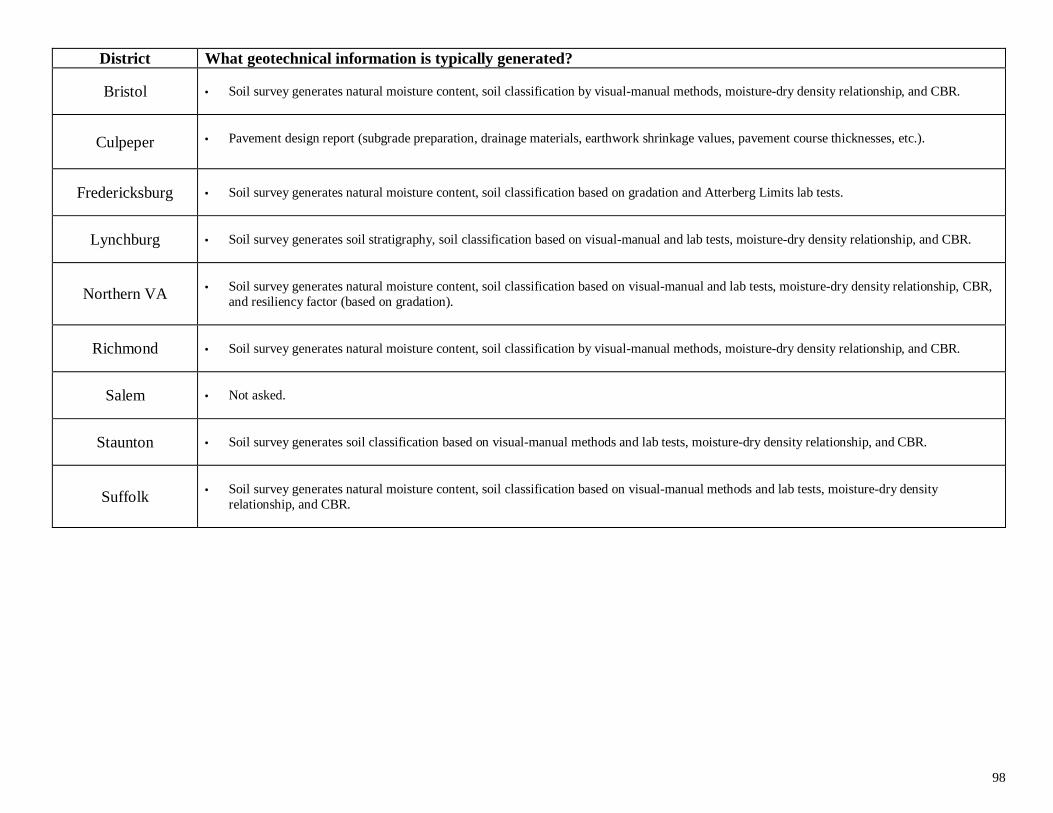
98
District What geotechnical information is typically generated?
Bristol • Soil survey generates natural moisture content, soil classification by visual-manual methods, moisture-dry density relationship, and CBR.
Culpeper • Pavement design report (subgrade preparation, drainage materials, earthwork shrinkage values, pavement course thicknesses, etc.).
Fredericksburg • Soil survey generates natural moisture content, soil classification based on gradation and Atterberg Limits lab tests.
Lynchburg • Soil survey generates soil stratigraphy, soil classification based on visual-manual and lab tests, moisture-dry density relationship, and CBR.
Northern VA • Soil survey generates natural moisture content, soil classification based on visual-manual and lab tests, moisture-dry density relationship, CBR,and resiliency factor (based on gradation).
Richmond • Soil survey generates natural moisture content, soil classification by visual-manual methods, moisture-dry density relationship, and CBR.
Salem • Not asked.
Staunton • Soil survey generates soil classification based on visual-manual methods and lab tests, moisture-dry density relationship, and CBR.
Suffolk
• Soil survey generates natural moisture content, soil classification based on visual-manual methods and lab tests, moisture-dry density
relationship, and CBR.
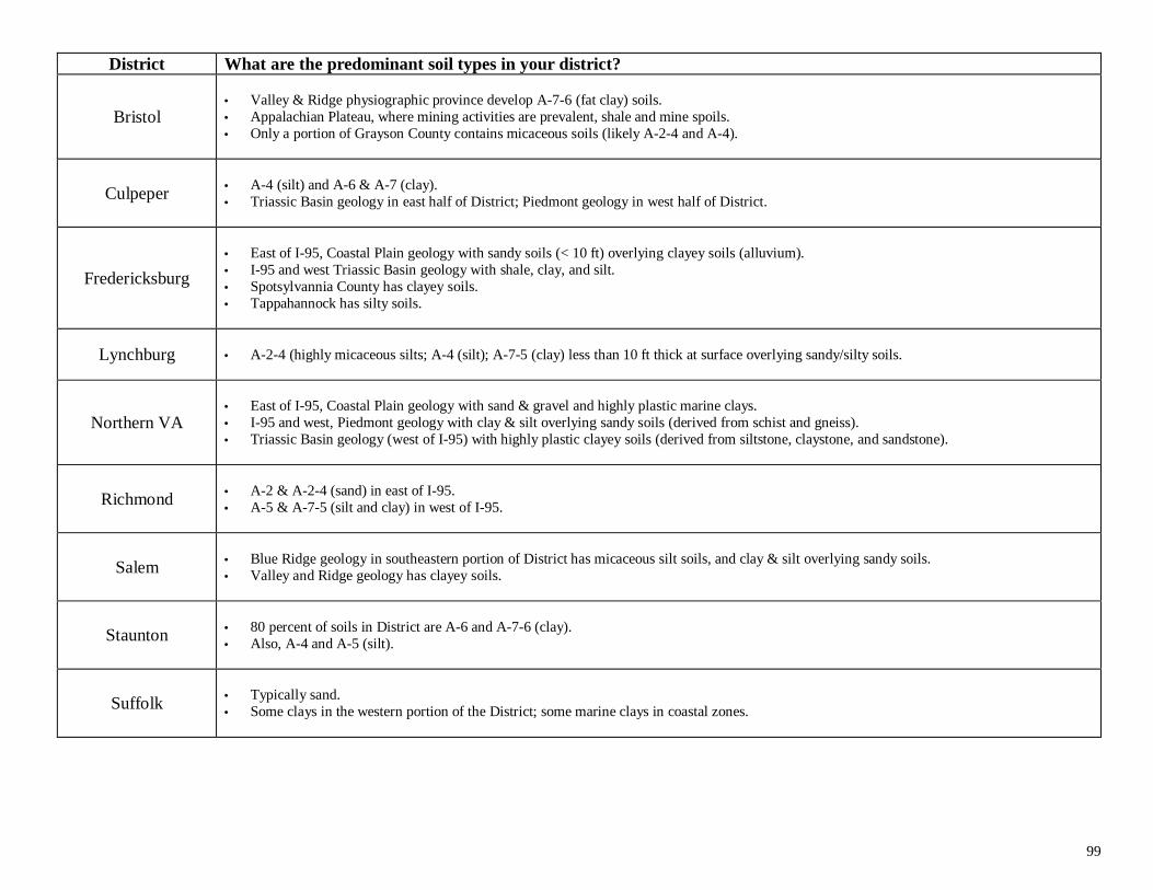
99
District What are the predominant soil types in your district?
Bristol• Valley & Ridge physiographic province develop A-7-6 (fat clay) soils.• Appalachian Plateau, where mining activities are prevalent, shale and mine spoils.• Only a portion of Grayson County contains micaceous soils (likely A-2-4 and A-4).
Culpeper
• A-4 (silt) and A-6 & A-7 (clay).• Triassic Basin geology in east half of District; Piedmont geology in west half of District.
Fredericksburg
• East of I-95, Coastal Plain geology with sandy soils (< 10 ft) overlying clayey soils (alluvium).• I-95 and west Triassic Basin geology with shale, clay, and silt.• Spotsylvannia County has clayey soils.• Tappahannock has silty soils.
Lynchburg • A-2-4 (highly micaceous silts; A-4 (silt); A-7-5 (clay) less than 10 ft thick at surface overlying sandy/silty soils.
Northern VA
• East of I-95, Coastal Plain geology with sand & gravel and highly plastic marine clays.• I-95 and west, Piedmont geology with clay & silt overlying sandy soils (derived from schist and gneiss).• Triassic Basin geology (west of I-95) with highly plastic clayey soils (derived from siltstone, claystone, and sandstone).
Richmond
• A-2 & A-2-4 (sand) in east of I-95.• A-5 & A-7-5 (silt and clay) in west of I-95.
Salem
• Blue Ridge geology in southeastern portion of District has micaceous silt soils, and clay & silt overlying sandy soils.• Valley and Ridge geology has clayey soils.
Staunton
• 80 percent of soils in District are A-6 and A-7-6 (clay).• Also, A-4 and A-5 (silt).
Suffolk
• Typically sand.• Some clays in the western portion of the District; some marine clays in coastal zones.
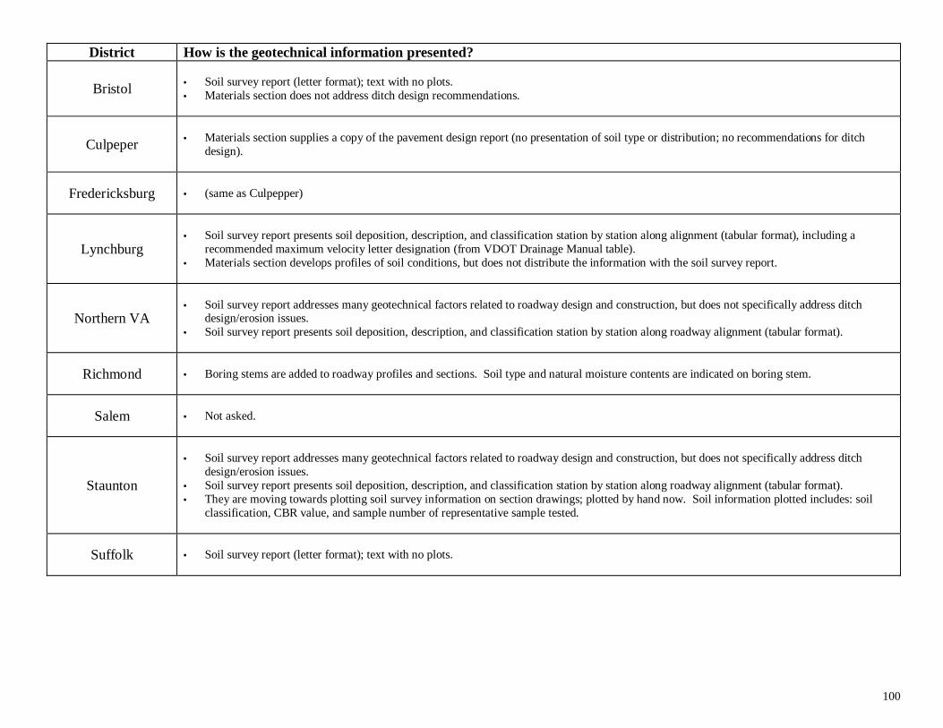
100
District How is the geotechnical information presented?
Bristol • Soil survey report (letter format); text with no plots.• Materials section does not address ditch design recommendations.
Culpeper
• Materials section supplies a copy of the pavement design report (no presentation of soil type or distribution; no recommendations for ditch
design).
Fredericksburg • (same as Culpepper)
Lynchburg
• Soil survey report presents soil deposition, description, and classification station by station along alignment (tabular format), including a
recommended maximum velocity letter designation (from VDOT Drainage Manual table).• Materials section develops profiles of soil conditions, but does not distribute the information with the soil survey report.
Northern VA• Soil survey report addresses many geotechnical factors related to roadway design and construction, but does not specifically address ditch
design/erosion issues.• Soil survey report presents soil deposition, description, and classification station by station along roadway alignment (tabular format).
Richmond • Boring stems are added to roadway profiles and sections. Soil type and natural moisture contents are indicated on boring stem.
Salem • Not asked.
Staunton
• Soil survey report addresses many geotechnical factors related to roadway design and construction, but does not specifically address ditch
design/erosion issues.• Soil survey report presents soil deposition, description, and classification station by station along roadway alignment (tabular format).• They are moving towards plotting soil survey information on section drawings; plotted by hand now. Soil information plotted includes: soil
classification, CBR value, and sample number of representative sample tested.
Suffolk • Soil survey report (letter format); text with no plots.
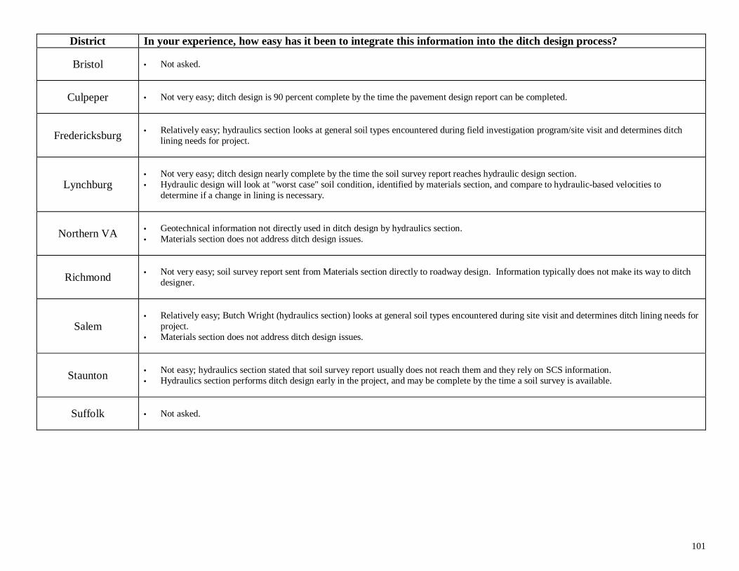
101
District In your experience, how easy has it been to integrate this information into the ditch design process?
Bristol • Not asked.
Culpeper • Not very easy; ditch design is 90 percent complete by the time the pavement design report can be completed.
Fredericksburg
• Relatively easy; hydraulics section looks at general soil types encountered during field investigation program/site visit and determines ditch
lining needs for project.
Lynchburg• Not very easy; ditch design nearly complete by the time the soil survey report reaches hydraulic design section.• Hydraulic design will look at "worst case" soil condition, identified by materials section, and compare to hydraulic-based velocities to
determine if a change in lining is necessary.
Northern VA
• Geotechnical information not directly used in ditch design by hydraulics section.• Materials section does not address ditch design issues.
Richmond
• Not very easy; soil survey report sent from Materials section directly to roadway design. Information typically does not make its way to ditch
designer.
Salem
• Relatively easy; Butch Wright (hydraulics section) looks at general soil types encountered during site visit and determines ditch lining needs for
project.• Materials section does not address ditch design issues.
Staunton
• Not easy; hydraulics section stated that soil survey report usually does not reach them and they rely on SCS information.• Hydraulics section performs ditch design early in the project, and may be complete by the time a soil survey is available.
Suffolk • Not asked.
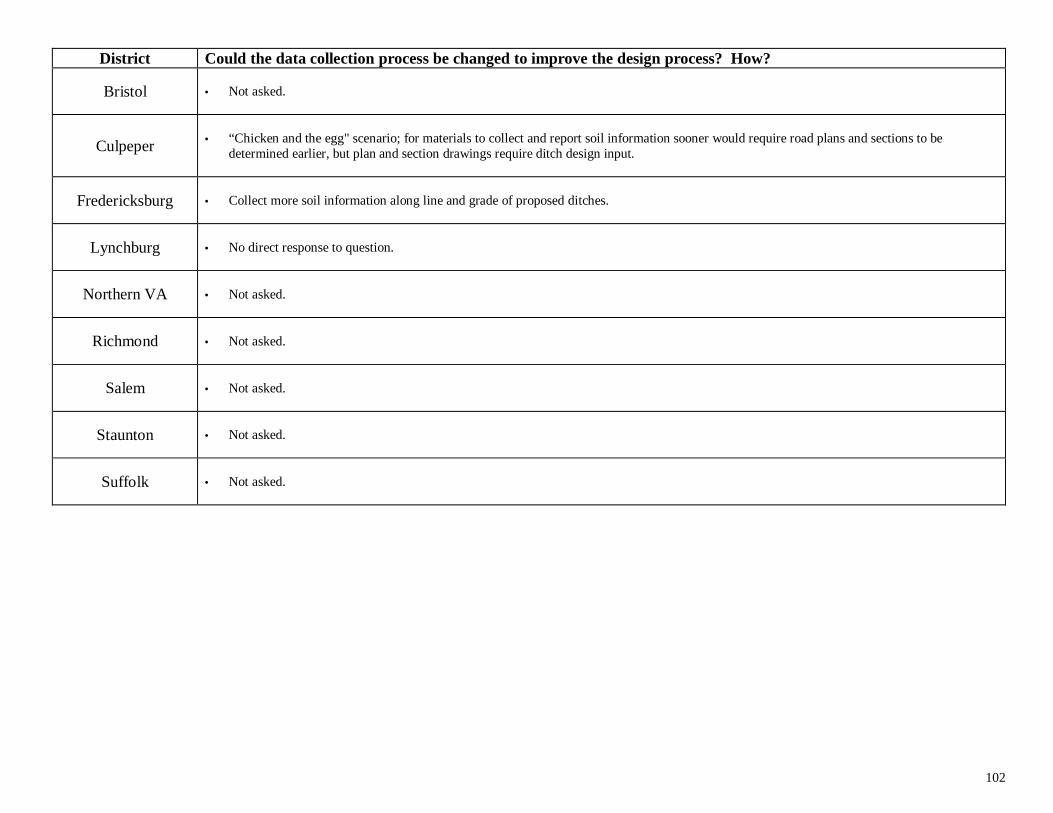
102
District Could the data collection process be changed to improve the design process? How?
Bristol • Not asked.
Culpeper
• “Chicken and the egg" scenario; for materials to collect and report soil information sooner would require road plans and sections to be
determined earlier, but plan and section drawings require ditch design input.
Fredericksburg • Collect more soil information along line and grade of proposed ditches.
Lynchburg • No direct response to question.
Northern VA • Not asked.
Richmond • Not asked.
Salem • Not asked.
Staunton • Not asked.
Suffolk • Not asked.
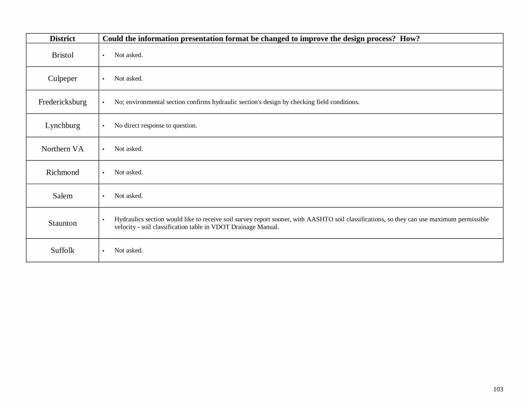
103
District Could the information presentation format be changed to improve the design process? How?
Bristol • Not asked.
Culpeper • Not asked.
Fredericksburg • No; environmental section confirms hydraulic section's design by checking field conditions.
Lynchburg • No direct response to question.
Northern VA • Not asked.
Richmond • Not asked.
Salem • Not asked.
Staunton • Hydraulics section would like to receive soil survey report sooner, with AASHTO soil classifications, so they can use maximum permissiblevelocity - soil classification table in VDOT Drainage Manual.
Suffolk • Not asked.
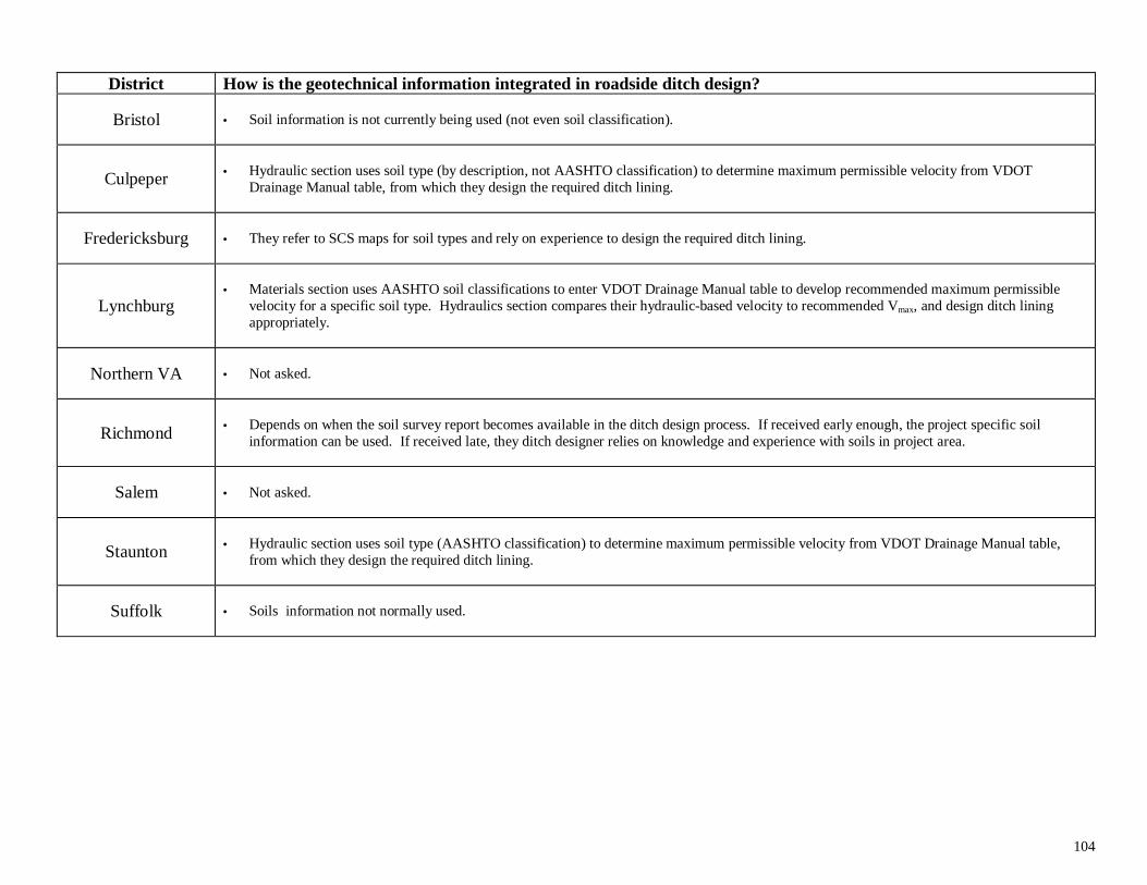
104
District How is the geotechnical information integrated in roadside ditch design?
Bristol • Soil information is not currently being used (not even soil classification).
Culpeper
• Hydraulic section uses soil type (by description, not AASHTO classification) to determine maximum permissible velocity from VDOT
Drainage Manual table, from which they design the required ditch lining.
Fredericksburg • They refer to SCS maps for soil types and rely on experience to design the required ditch lining.
Lynchburg
• Materials section uses AASHTO soil classifications to enter VDOT Drainage Manual table to develop recommended maximum permissible
velocity for a specific soil type. Hydraulics section compares their hydraulic-based velocity to recommended Vmax, and design ditch liningappropriately.
Northern VA • Not asked.
Richmond • Depends on when the soil survey report becomes available in the ditch design process. If received early enough, the project specific soilinformation can be used. If received late, they ditch designer relies on knowledge and experience with soils in project area.
Salem • Not asked.
Staunton • Hydraulic section uses soil type (AASHTO classification) to determine maximum permissible velocity from VDOT Drainage Manual table,from which they design the required ditch lining.
Suffolk • Soils information not normally used.
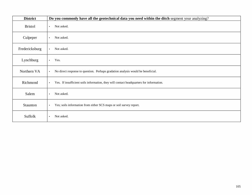
105
District Do you commonly have all the geotechnical data you need within the ditch segment your analyzing?
Bristol • Not asked.
Culpeper • Not asked.
Fredericksburg • Not asked.
Lynchburg • Yes.
Northern VA • No direct response to question. Perhaps gradation analysis would be beneficial.
Richmond • Yes. If insufficient soils information, they will contact headquarters for information.
Salem • Not asked.
Staunton • Yes; soils information from either SCS maps or soil survey report.
Suffolk • Not asked.
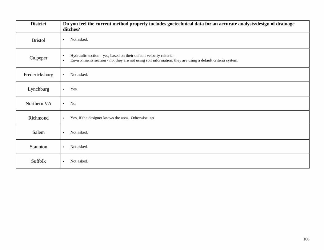
106
District Do you feel the current method properly includes goetechnical data for an accurate analysis/design of drainageditches?
Bristol • Not asked.
Culpeper • Hydraulic section - yes; based on their default velocity criteria.• Environments section - no; they are not using soil information, they are using a default criteria system.
Fredericksburg • Not asked.
Lynchburg • Yes.
Northern VA • No.
Richmond • Yes, if the designer knows the area. Otherwise, no.
Salem • Not asked.
Staunton • Not asked.
Suffolk • Not asked.
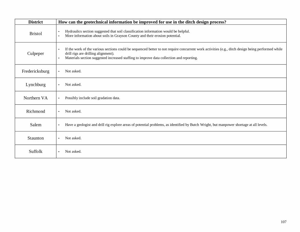
107
District How can the geotechnical information be improved for use in the ditch design process?
Bristol • Hydraulics section suggested that soil classification information would be helpful.• More information about soils in Grayson County and their erosion potential.
Culpeper
• If the work of the various sections could be sequenced better to not require concurrent work activities (e.g., ditch design being performed while
drill rigs are drilling alignment).• Materials section suggested increased staffing to improve data collection and reporting.
Fredericksburg • Not asked.
Lynchburg • Not asked.
Northern VA • Possibly include soil gradation data.
Richmond • Not asked.
Salem • Have a geologist and drill rig explore areas of potential problems, as identified by Butch Wright, but manpower shortage at all levels.
Staunton • Not asked.
Suffolk • Not asked.
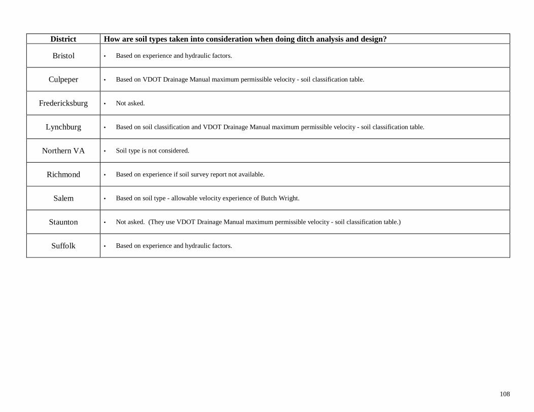
108
District How are soil types taken into consideration when doing ditch analysis and design?
Bristol • Based on experience and hydraulic factors.
Culpeper • Based on VDOT Drainage Manual maximum permissible velocity - soil classification table.
Fredericksburg • Not asked.
Lynchburg • Based on soil classification and VDOT Drainage Manual maximum permissible velocity - soil classification table.
Northern VA • Soil type is not considered.
Richmond • Based on experience if soil survey report not available.
Salem • Based on soil type - allowable velocity experience of Butch Wright.
Staunton • Not asked. (They use VDOT Drainage Manual maximum permissible velocity - soil classification table.)
Suffolk • Based on experience and hydraulic factors.
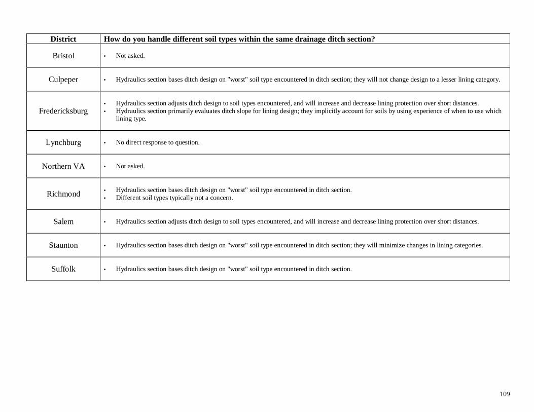
109
District How do you handle different soil types within the same drainage ditch section?
Bristol • Not asked.
Culpeper • Hydraulics section bases ditch design on "worst" soil type encountered in ditch section; they will not change design to a lesser lining category.
Fredericksburg
• Hydraulics section adjusts ditch design to soil types encountered, and will increase and decrease lining protection over short distances.• Hydraulics section primarily evaluates ditch slope for lining design; they implicitly account for soils by using experience of when to use which
lining type.
Lynchburg • No direct response to question.
Northern VA • Not asked.
Richmond • Hydraulics section bases ditch design on "worst" soil type encountered in ditch section.• Different soil types typically not a concern.
Salem • Hydraulics section adjusts ditch design to soil types encountered, and will increase and decrease lining protection over short distances.
Staunton • Hydraulics section bases ditch design on "worst" soil type encountered in ditch section; they will minimize changes in lining categories.
Suffolk • Hydraulics section bases ditch design on "worst" soil type encountered in ditch section.
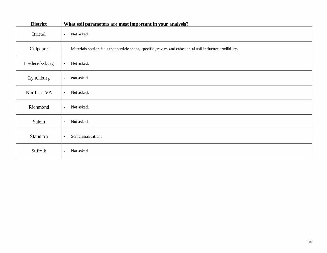
110
District What soil parameters are most important in your analysis?
Bristol • Not asked.
Culpeper • Materials section feels that particle shape, specific gravity, and cohesion of soil influence erodibility.
Fredericksburg • Not asked.
Lynchburg • Not asked.
Northern VA • Not asked.
Richmond • Not asked.
Salem • Not asked.
Staunton • Soil classification.
Suffolk • Not asked.
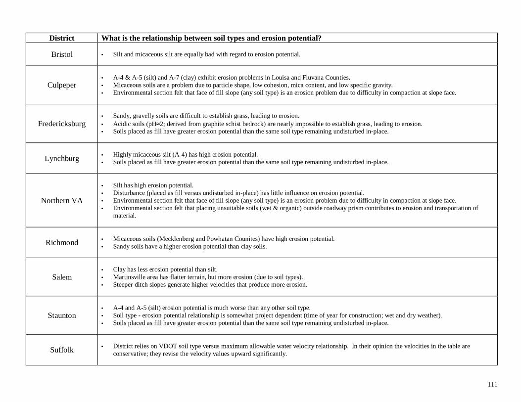
111
District What is the relationship between soil types and erosion potential?
Bristol • Silt and micaceous silt are equally bad with regard to erosion potential.
Culpeper• A-4 & A-5 (silt) and A-7 (clay) exhibit erosion problems in Louisa and Fluvana Counties.• Micaceous soils are a problem due to particle shape, low cohesion, mica content, and low specific gravity.• Environmental section felt that face of fill slope (any soil type) is an erosion problem due to difficulty in compaction at slope face.
Fredericksburg• Sandy, gravelly soils are difficult to establish grass, leading to erosion.• Acidic soils (pH≈2; derived from graphite schist bedrock) are nearly impossible to establish grass, leading to erosion.• Soils placed as fill have greater erosion potential than the same soil type remaining undisturbed in-place.
Lynchburg
• Highly micaceous silt (A-4) has high erosion potential.• Soils placed as fill have greater erosion potential than the same soil type remaining undisturbed in-place.
Northern VA
• Silt has high erosion potential.• Disturbance (placed as fill versus undisturbed in-place) has little influence on erosion potential.• Environmental section felt that face of fill slope (any soil type) is an erosion problem due to difficulty in compaction at slope face.• Environmental section felt that placing unsuitable soils (wet & organic) outside roadway prism contributes to erosion and transportation of
material.
Richmond
• Micaceous soils (Mecklenberg and Powhatan Counites) have high erosion potential.• Sandy soils have a higher erosion potential than clay soils.
Salem• Clay has less erosion potential than silt.• Martinsville area has flatter terrain, but more erosion (due to soil types).• Steeper ditch slopes generate higher velocities that produce more erosion.
Staunton
• A-4 and A-5 (silt) erosion potential is much worse than any other soil type.• Soil type - erosion potential relationship is somewhat project dependent (time of year for construction; wet and dry weather).• Soils placed as fill have greater erosion potential than the same soil type remaining undisturbed in-place.
Suffolk • District relies on VDOT soil type versus maximum allowable water velocity relationship. In their opinion the velocities in the table areconservative; they revise the velocity values upward significantly.
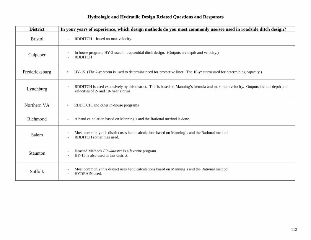
112
Hydrologic and Hydraulic Design Related Questions and Responses
District In your years of experience, which design methods do you most commonly use/see used in roadside ditch design?
Bristol • RDDITCH – based on max velocity.
Culpeper • In house program, HY-2 used in trapezoidal ditch design. (Outputs are depth and velocity.)• RDDITCH
Fredericksburg • HY-15. (The 2-yr storm is used to determine need for protective liner. The 10-yr storm used for determining capacity.)
Lynchburg • RDDITCH is used extensively by this district. This is based on Manning’s formula and maximum velocity. Outputs include depth andvelocities of 2- and 10- year storms.
Northern VA • RDDITCH, and other in-house programs
Richmond • A hand calculation based on Manning’s and the Rational method is done.
Salem • Most commonly this district uses hand calculations based on Manning’s and the Rational method• RDDITCH sometimes used.
Staunton • Heastad Methods FlowMaster is a favorite program.• HY-15 is also used in this district.
Suffolk • Most commonly this district uses hand calculations based on Manning’s and the Rational method• HYDRAIN used.
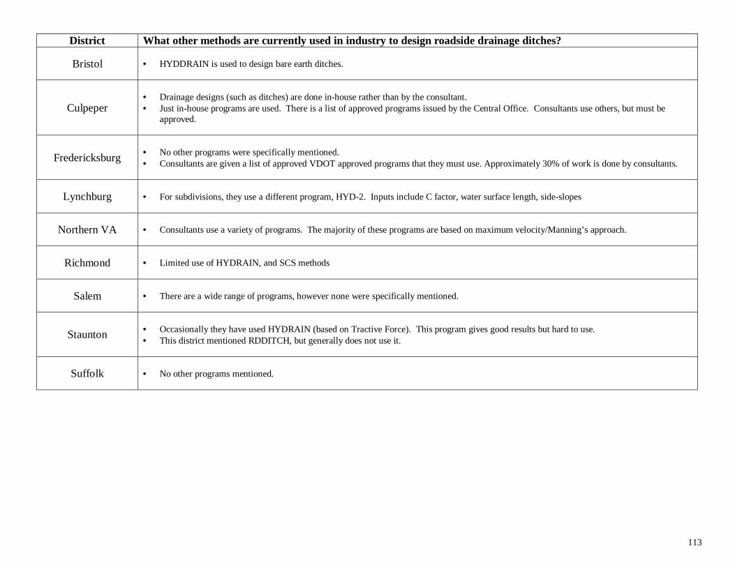
113
District What other methods are currently used in industry to design roadside drainage ditches?
Bristol • HYDDRAIN is used to design bare earth ditches.
Culpeper• Drainage designs (such as ditches) are done in-house rather than by the consultant.• Just in-house programs are used. There is a list of approved programs issued by the Central Office. Consultants use others, but must be
approved.
Fredericksburg • No other programs were specifically mentioned.• Consultants are given a list of approved VDOT approved programs that they must use. Approximately 30% of work is done by consultants.
Lynchburg • For subdivisions, they use a different program, HYD-2. Inputs include C factor, water surface length, side-slopes
Northern VA • Consultants use a variety of programs. The majority of these programs are based on maximum velocity/Manning’s approach.
Richmond • Limited use of HYDRAIN, and SCS methods
Salem • There are a wide range of programs, however none were specifically mentioned.
Staunton • Occasionally they have used HYDRAIN (based on Tractive Force). This program gives good results but hard to use.• This district mentioned RDDITCH, but generally does not use it.
Suffolk • No other programs mentioned.
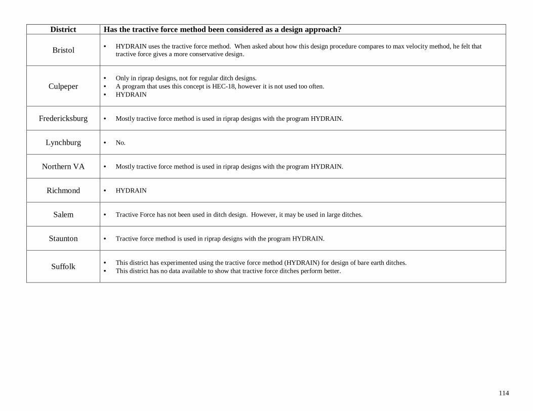
114
District Has the tractive force method been considered as a design approach?
Bristol • HYDRAIN uses the tractive force method. When asked about how this design procedure compares to max velocity method, he felt thattractive force gives a more conservative design.
Culpeper• Only in riprap designs, not for regular ditch designs.• A program that uses this concept is HEC-18, however it is not used too often.• HYDRAIN
Fredericksburg • Mostly tractive force method is used in riprap designs with the program HYDRAIN.
Lynchburg • No.
Northern VA • Mostly tractive force method is used in riprap designs with the program HYDRAIN.
Richmond • HYDRAIN
Salem • Tractive Force has not been used in ditch design. However, it may be used in large ditches.
Staunton • Tractive force method is used in riprap designs with the program HYDRAIN.
Suffolk • This district has experimented using the tractive force method (HYDRAIN) for design of bare earth ditches.• This district has no data available to show that tractive force ditches perform better.
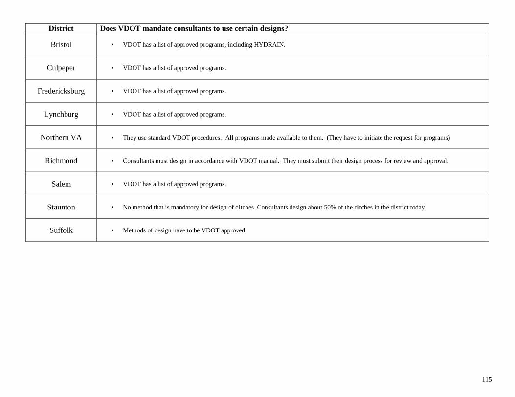
115
District Does VDOT mandate consultants to use certain designs?
Bristol • VDOT has a list of approved programs, including HYDRAIN.
Culpeper • VDOT has a list of approved programs.
Fredericksburg • VDOT has a list of approved programs.
Lynchburg • VDOT has a list of approved programs.
Northern VA • They use standard VDOT procedures. All programs made available to them. (They have to initiate the request for programs)
Richmond • Consultants must design in accordance with VDOT manual. They must submit their design process for review and approval.
Salem • VDOT has a list of approved programs.
Staunton • No method that is mandatory for design of ditches. Consultants design about 50% of the ditches in the district today.
Suffolk • Methods of design have to be VDOT approved.
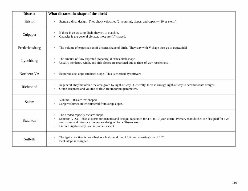
116
District What dictates the shape of the ditch?
Bristol • Standard ditch design. They check velocities (2-yr storm), slopes, and capacity (10-yr storm)
Culpeper • If there is an existing ditch, they try to match it.• Capacity is the general dictator, most are “v” shaped.
Fredericksburg • The volume of expected runoff dictates shape of ditch. They stay with V shape then go to trapezoidal
Lynchburg • The amount of flow expected (capacity) dictates ditch shape.• Usually the depth, width, and side-slopes are restricted due to right-of-way restrictions.
Northern VA • Required side-slope and back-slope. This is checked by software
Richmond • In general, they maximize the area given by right-of-way. Generally, there is enough right-of-way to accommodate designs.• Grade steepness and volume of flow are important parameters.
Salem • Volume. 80% are “v” shaped.• Larger volumes are encountered from steep slopes.
Staunton
• The needed capacity dictates shape.• Staunton VDOT looks at storm frequencies and designs capacities for a 5- to 10-year storm. Primary road ditches are designed for a 25-
year storm and interstate ditches are designed for a 50-year storm.• Limited right-of-way is an important aspect.
Suffolk • The typical section is described as a horizontal run of 3 ft. and a vertical rise of 18”.• Back-slope is designed.
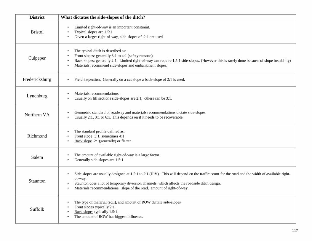
117
District What dictates the side-slopes of the ditch?
Bristol• Limited right-of-way is an important constraint.• Typical slopes are 1.5:1• Given a larger right-of-way, side-slopes of 2:1 are used.
Culpeper
• The typical ditch is described as:• Front slopes: generally 3:1 to 4:1 (safety reasons)• Back-slopes: generally 2:1. Limited right-of-way can require 1.5:1 side-slopes. (However this is rarely done because of slope instability)• Materials recommend side-slopes and embankment slopes.
Fredericksburg • Field inspection. Generally on a cut slope a back-slope of 2:1 is used.
Lynchburg • Materials recommendations.• Usually on fill sections side-slopes are 2:1, others can be 3:1.
Northern VA • Geometric standard of roadway and materials recommendations dictate side-slopes.• Usually 2:1, 3:1 or 6:1. This depends on if it needs to be recoverable.
Richmond• The standard profile defined as:• Front slope 3:1, sometimes 4:1• Back slope 2:1(generally) or flatter
Salem • The amount of available right-of-way is a large factor.• Generally side-slopes are 1.5:1
Staunton
• Side slopes are usually designed at 1.5:1 to 2:1 (H:V). This will depend on the traffic count for the road and the width of available right-of-way.
• Staunton does a lot of temporary diversion channels, which affects the roadside ditch design.• Materials recommendations, slope of the road, amount of right-of-way.
Suffolk
• The type of material (soil), and amount of ROW dictate side-slopes• Front slopes typically 2:1• Back slopes typically 1.5:1• The amount of ROW has biggest influence.
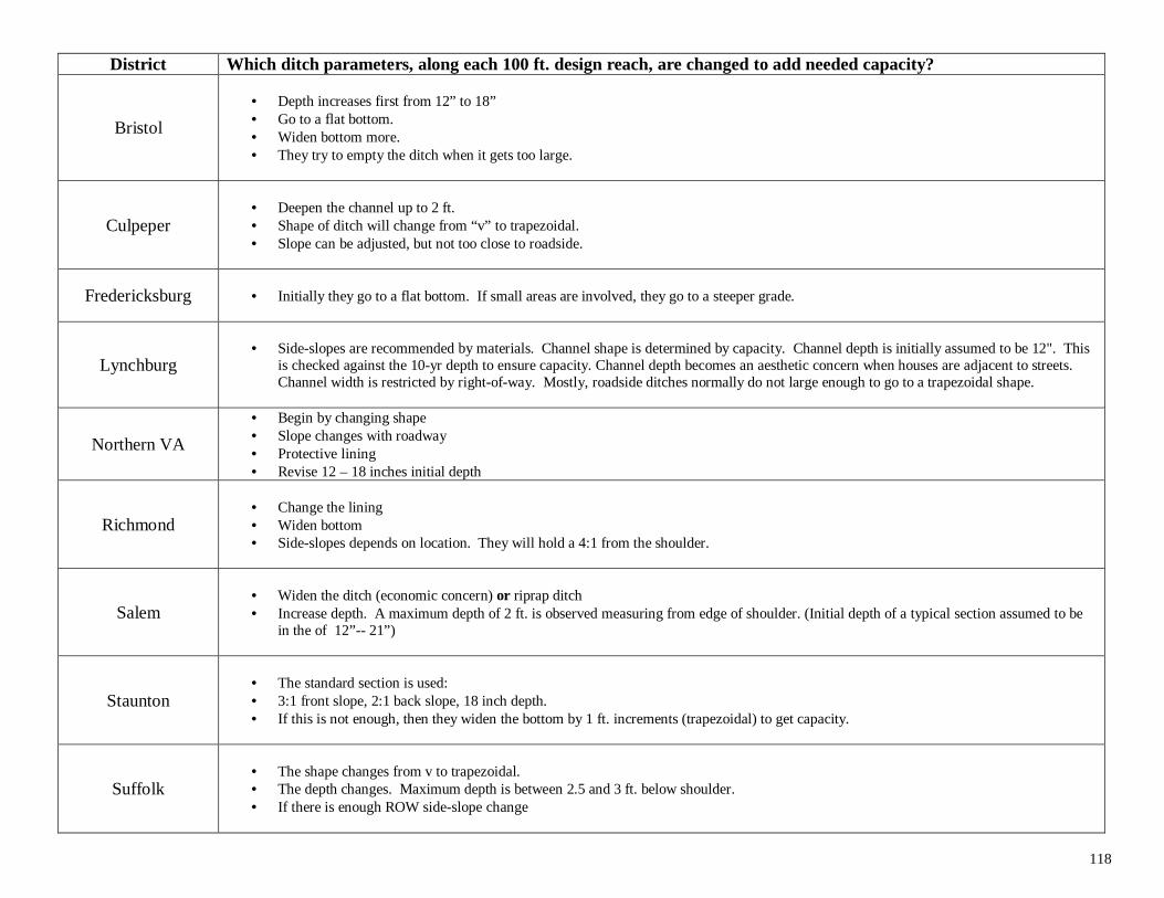
118
District Which ditch parameters, along each 100 ft. design reach, are changed to add needed capacity?
Bristol
• Depth increases first from 12” to 18”• Go to a flat bottom.• Widen bottom more.• They try to empty the ditch when it gets too large.
Culpeper• Deepen the channel up to 2 ft.• Shape of ditch will change from “v” to trapezoidal.• Slope can be adjusted, but not too close to roadside.
Fredericksburg • Initially they go to a flat bottom. If small areas are involved, they go to a steeper grade.
Lynchburg• Side-slopes are recommended by materials. Channel shape is determined by capacity. Channel depth is initially assumed to be 12". This
is checked against the 10-yr depth to ensure capacity. Channel depth becomes an aesthetic concern when houses are adjacent to streets.Channel width is restricted by right-of-way. Mostly, roadside ditches normally do not large enough to go to a trapezoidal shape.
Northern VA
• Begin by changing shape• Slope changes with roadway• Protective lining• Revise 12 – 18 inches initial depth
Richmond• Change the lining• Widen bottom• Side-slopes depends on location. They will hold a 4:1 from the shoulder.
Salem• Widen the ditch (economic concern) or riprap ditch• Increase depth. A maximum depth of 2 ft. is observed measuring from edge of shoulder. (Initial depth of a typical section assumed to be
in the of 12”-- 21”)
Staunton• The standard section is used:• 3:1 front slope, 2:1 back slope, 18 inch depth.• If this is not enough, then they widen the bottom by 1 ft. increments (trapezoidal) to get capacity.
Suffolk• The shape changes from v to trapezoidal.• The depth changes. Maximum depth is between 2.5 and 3 ft. below shoulder.• If there is enough ROW side-slope change
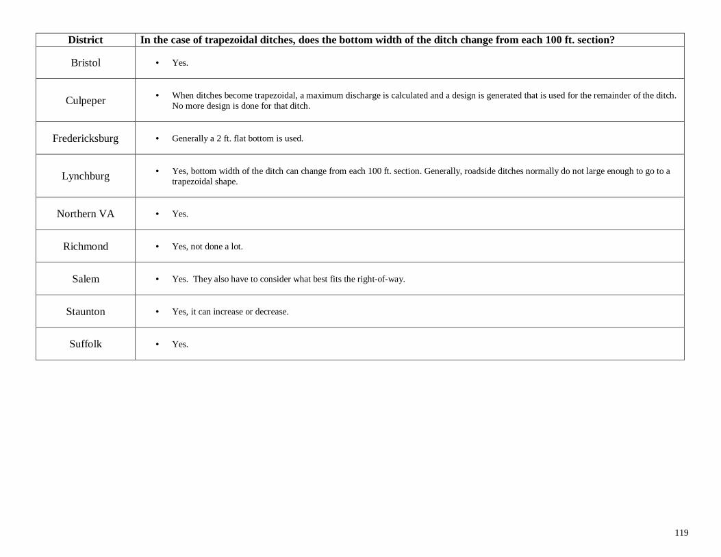
119
District In the case of trapezoidal ditches, does the bottom width of the ditch change from each 100 ft. section?
Bristol • Yes.
Culpeper • When ditches become trapezoidal, a maximum discharge is calculated and a design is generated that is used for the remainder of the ditch.No more design is done for that ditch.
Fredericksburg • Generally a 2 ft. flat bottom is used.
Lynchburg • Yes, bottom width of the ditch can change from each 100 ft. section. Generally, roadside ditches normally do not large enough to go to atrapezoidal shape.
Northern VA • Yes.
Richmond • Yes, not done a lot.
Salem • Yes. They also have to consider what best fits the right-of-way.
Staunton • Yes, it can increase or decrease.
Suffolk • Yes.
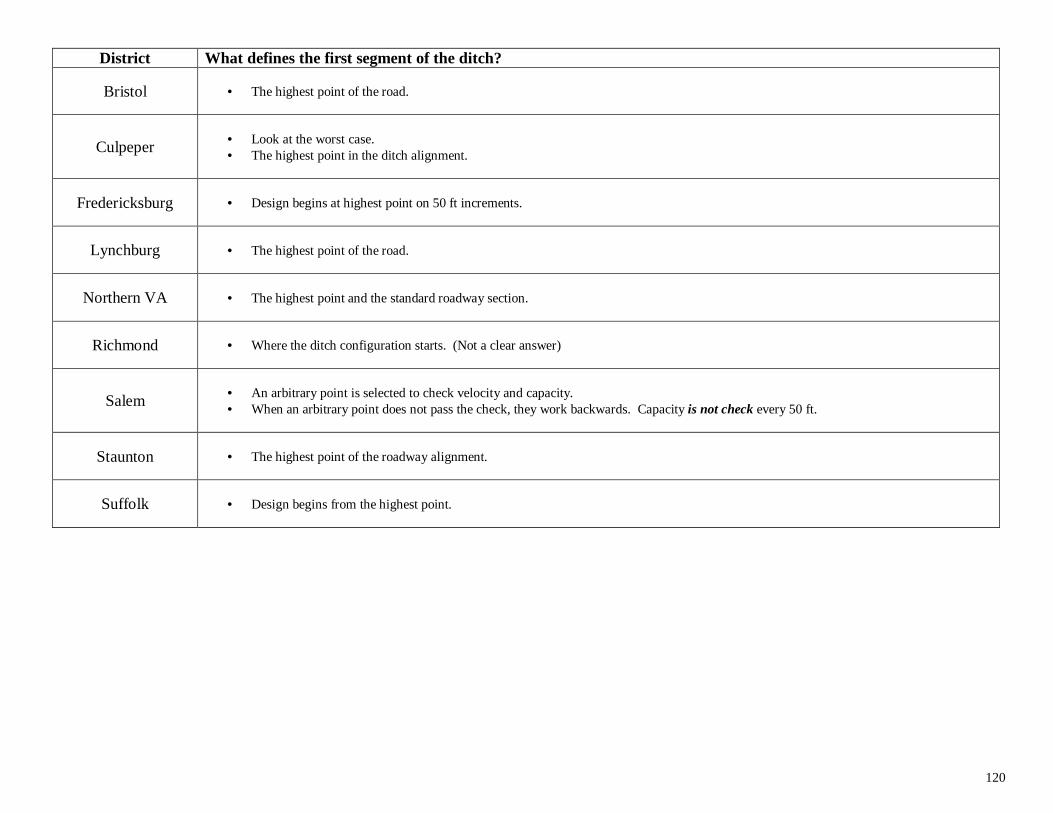
120
District What defines the first segment of the ditch?
Bristol • The highest point of the road.
Culpeper • Look at the worst case.• The highest point in the ditch alignment.
Fredericksburg • Design begins at highest point on 50 ft increments.
Lynchburg • The highest point of the road.
Northern VA • The highest point and the standard roadway section.
Richmond • Where the ditch configuration starts. (Not a clear answer)
Salem • An arbitrary point is selected to check velocity and capacity.• When an arbitrary point does not pass the check, they work backwards. Capacity is not check every 50 ft.
Staunton • The highest point of the roadway alignment.
Suffolk • Design begins from the highest point.
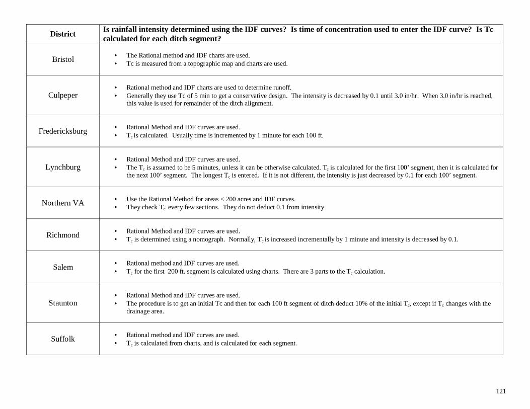
121
DistrictIs rainfall intensity determined using the IDF curves? Is time of concentration used to enter the IDF curve? Is Tccalculated for each ditch segment?
Bristol • The Rational method and IDF charts are used.• Tc is measured from a topographic map and charts are used.
Culpeper• Rational method and IDF charts are used to determine runoff.• Generally they use Tc of 5 min to get a conservative design. The intensity is decreased by 0.1 until 3.0 in/hr. When 3.0 in/hr is reached,
this value is used for remainder of the ditch alignment.
Fredericksburg • Rational Method and IDF curves are used.• Tc is calculated. Usually time is incremented by 1 minute for each 100 ft.
Lynchburg• Rational Method and IDF curves are used.• The Tc is assumed to be 5 minutes, unless it can be otherwise calculated. Tc is calculated for the first 100’ segment, then it is calculated for
the next 100’ segment. The longest Tc is entered. If it is not different, the intensity is just decreased by 0.1 for each 100’ segment.
Northern VA • Use the Rational Method for areas < 200 acres and IDF curves.• They check Tc every few sections. They do not deduct 0.1 from intensity
Richmond • Rational Method and IDF curves are used.• Tc is determined using a nomograph. Normally, Tc is increased incrementally by 1 minute and intensity is decreased by 0.1.
Salem • Rational method and IDF curves are used.• Tc for the first 200 ft. segment is calculated using charts. There are 3 parts to the Tc calculation.
Staunton• Rational Method and IDF curves are used.• The procedure is to get an initial Tc and then for each 100 ft segment of ditch deduct 10% of the initial Tc, except if Tc changes with the
drainage area.
Suffolk • Rational method and IDF curves are used.• Tc is calculated from charts, and is calculated for each segment.
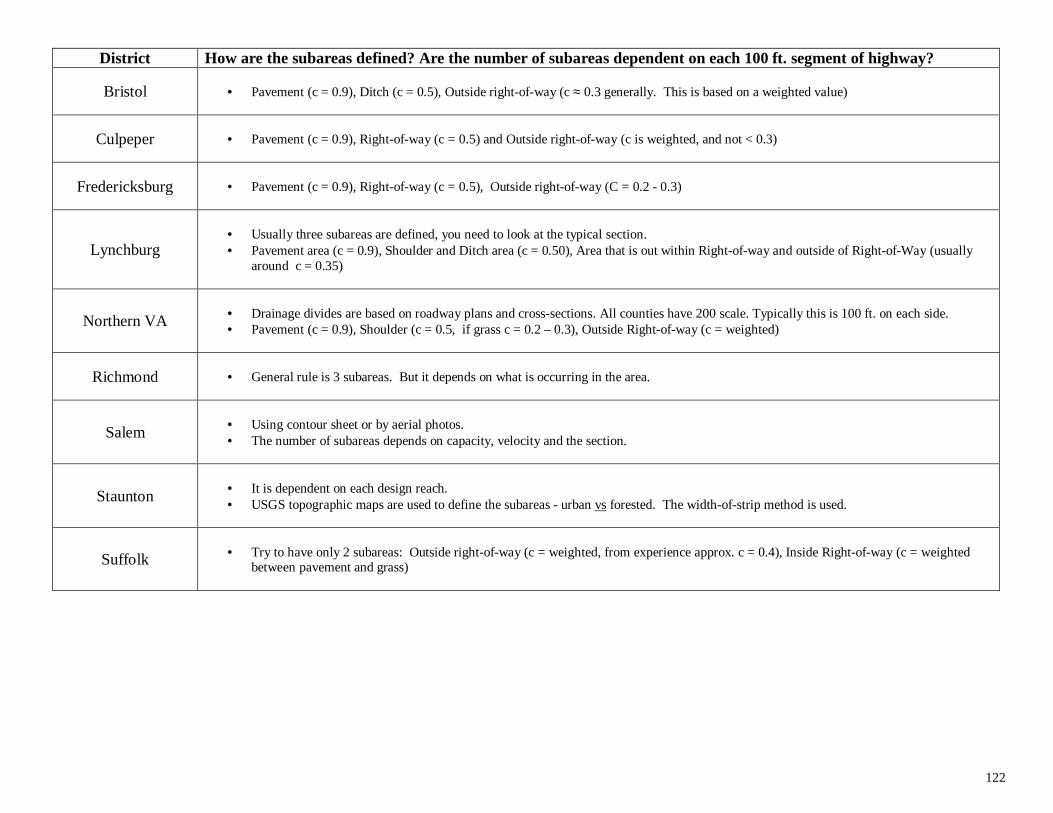
122
District How are the subareas defined? Are the number of subareas dependent on each 100 ft. segment of highway?
Bristol • Pavement (c = 0.9), Ditch (c = 0.5), Outside right-of-way (c ≈ 0.3 generally. This is based on a weighted value)
Culpeper • Pavement (c = 0.9), Right-of-way (c = 0.5) and Outside right-of-way (c is weighted, and not < 0.3)
Fredericksburg • Pavement (c = 0.9), Right-of-way (c = 0.5), Outside right-of-way (C = 0.2 - 0.3)
Lynchburg• Usually three subareas are defined, you need to look at the typical section.• Pavement area (c = 0.9), Shoulder and Ditch area (c = 0.50), Area that is out within Right-of-way and outside of Right-of-Way (usually
around c = 0.35)
Northern VA • Drainage divides are based on roadway plans and cross-sections. All counties have 200 scale. Typically this is 100 ft. on each side.• Pavement (c = 0.9), Shoulder (c = 0.5, if grass c = 0.2 – 0.3), Outside Right-of-way (c = weighted)
Richmond • General rule is 3 subareas. But it depends on what is occurring in the area.
Salem • Using contour sheet or by aerial photos.• The number of subareas depends on capacity, velocity and the section.
Staunton • It is dependent on each design reach.• USGS topographic maps are used to define the subareas - urban vs forested. The width-of-strip method is used.
Suffolk • Try to have only 2 subareas: Outside right-of-way (c = weighted, from experience approx. c = 0.4), Inside Right-of-way (c = weightedbetween pavement and grass)
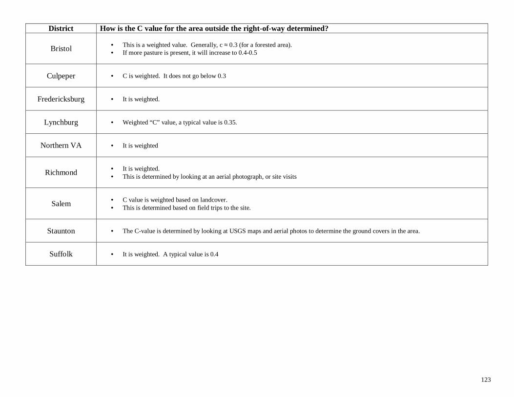
123
District How is the C value for the area outside the right-of-way determined?
Bristol • This is a weighted value. Generally, c ≈ 0.3 (for a forested area).• If more pasture is present, it will increase to 0.4-0.5
Culpeper • C is weighted. It does not go below 0.3
Fredericksburg • It is weighted.
Lynchburg • Weighted “C” value, a typical value is 0.35.
Northern VA • It is weighted
Richmond • It is weighted.• This is determined by looking at an aerial photograph, or site visits
Salem • C value is weighted based on landcover.• This is determined based on field trips to the site.
Staunton • The C-value is determined by looking at USGS maps and aerial photos to determine the ground covers in the area.
Suffolk • It is weighted. A typical value is 0.4

124
District How are the widths of strip determined for each subarea, particularly the area outside of the right-of-way?
Bristol • The width of strip is determined by looking at a topographic map• If the width of strip exceeds 200-300 ft, they will truncate it .
Culpeper • Use a topographic map.• As a rule, a width of 100 ft is used.
Fredericksburg • Field inspection.
Lynchburg• The drainage area is marked on a USGS Contour map. The centerline is marked every 100’.• A line is drawn perpendicular to the centerline at each 100’ interval. The length along that line is measured (from centerline to top
drainage area).
Northern VA • On-site visits.
Richmond • A map is used to determine drainage breaks.
Salem • Width of strip method is not usually used.• A subarea method is preferred opposed to a width.
Staunton • By using USGS maps or internal (district) maps done in the 1950’s
Suffolk • They do not use a map. Using a map often time over designs.• A standard of 100 ft. strip width for the area outside of the Right-of-Way.
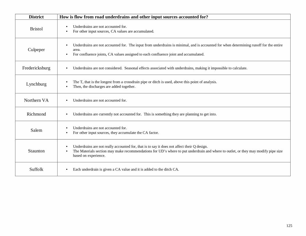
125
District How is flow from road underdrains and other input sources accounted for?
Bristol • Underdrains are not accounted for.• For other input sources, CA values are accumulated.
Culpeper• Underdrains are not accounted for. The input from underdrains is minimal, and is accounted for when determining runoff for the entire
area.• For confluence joints, CA values assigned to each confluence joint and accumulated.
Fredericksburg • Underdrains are not considered. Seasonal effects associated with underdrains, making it impossible to calculate.
Lynchburg • The Tc that is the longest from a crossdrain pipe or ditch is used, above this point of analysis.• Then, the discharges are added together.
Northern VA • Underdrains are not accounted for.
Richmond • Underdrains are currently not accounted for. This is something they are planning to get into.
Salem • Underdrains are not accounted for.• For other input sources, they accumulate the CA factor.
Staunton• Underdrains are not really accounted for, that is to say it does not affect their Q design.• The Materials section may make recommendations for UD’s where to put underdrain and where to outlet, or they may modify pipe size
based on experience.
Suffolk • Each underdrain is given a CA value and it is added to the ditch CA.
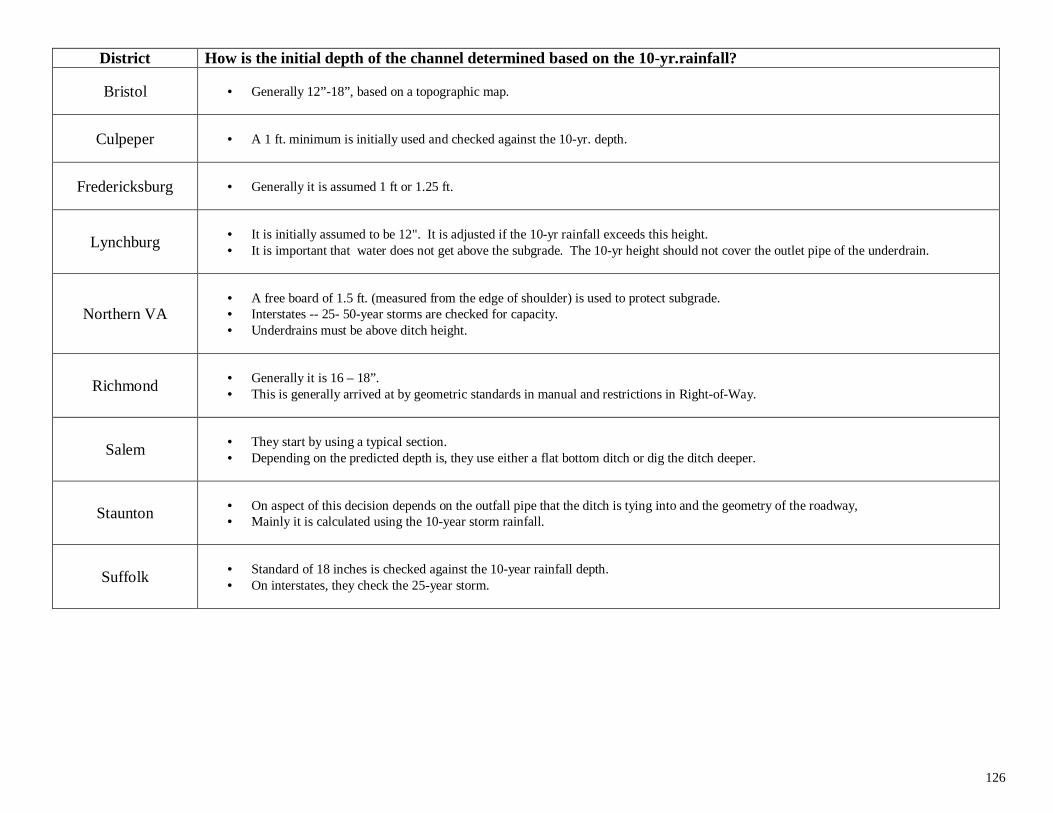
126
District How is the initial depth of the channel determined based on the 10-yr.rainfall?
Bristol • Generally 12”-18”, based on a topographic map.
Culpeper • A 1 ft. minimum is initially used and checked against the 10-yr. depth.
Fredericksburg • Generally it is assumed 1 ft or 1.25 ft.
Lynchburg • It is initially assumed to be 12". It is adjusted if the 10-yr rainfall exceeds this height.• It is important that water does not get above the subgrade. The 10-yr height should not cover the outlet pipe of the underdrain.
Northern VA• A free board of 1.5 ft. (measured from the edge of shoulder) is used to protect subgrade.• Interstates -- 25- 50-year storms are checked for capacity.• Underdrains must be above ditch height.
Richmond • Generally it is 16 – 18”.• This is generally arrived at by geometric standards in manual and restrictions in Right-of-Way.
Salem • They start by using a typical section.• Depending on the predicted depth is, they use either a flat bottom ditch or dig the ditch deeper.
Staunton • On aspect of this decision depends on the outfall pipe that the ditch is tying into and the geometry of the roadway,• Mainly it is calculated using the 10-year storm rainfall.
Suffolk • Standard of 18 inches is checked against the 10-year rainfall depth.• On interstates, they check the 25-year storm.
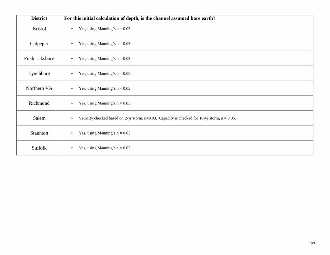
127
District For this initial calculation of depth, is the channel assumed bare earth?
Bristol • Yes, using Manning’s n = 0.03.
Culpeper • Yes, using Manning’s n = 0.03.
Fredericksburg • Yes, using Manning’s n = 0.03.
Lynchburg • Yes, using Manning’s n = 0.03.
Northern VA • Yes, using Manning’s n = 0.03.
Richmond • Yes, using Manning’s n = 0.03.
Salem • Velocity checked based on 2-yr storm, n=0.03. Capacity is checked for 10-yr storm, n = 0.05.
Staunton • Yes, using Manning’s n = 0.03.
Suffolk • Yes, using Manning’s n = 0.03.
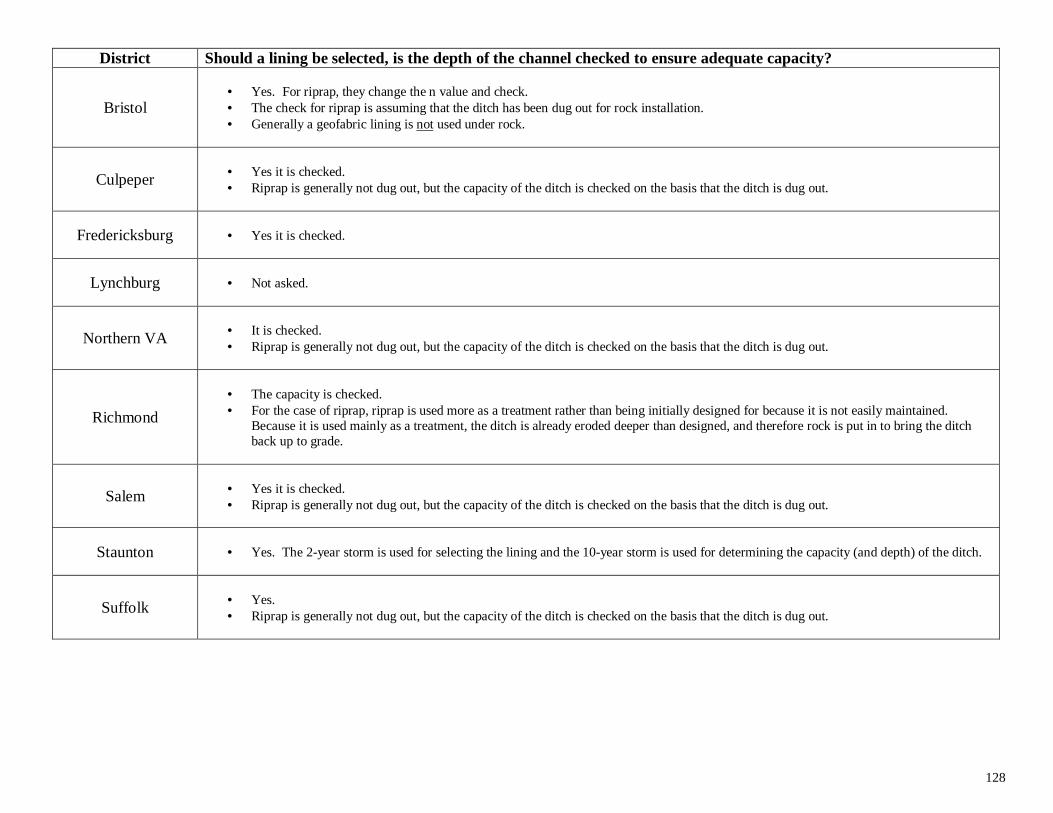
128
District Should a lining be selected, is the depth of the channel checked to ensure adequate capacity?
Bristol• Yes. For riprap, they change the n value and check.• The check for riprap is assuming that the ditch has been dug out for rock installation.• Generally a geofabric lining is not used under rock.
Culpeper • Yes it is checked.• Riprap is generally not dug out, but the capacity of the ditch is checked on the basis that the ditch is dug out.
Fredericksburg • Yes it is checked.
Lynchburg • Not asked.
Northern VA • It is checked.• Riprap is generally not dug out, but the capacity of the ditch is checked on the basis that the ditch is dug out.
Richmond
• The capacity is checked.• For the case of riprap, riprap is used more as a treatment rather than being initially designed for because it is not easily maintained.
Because it is used mainly as a treatment, the ditch is already eroded deeper than designed, and therefore rock is put in to bring the ditchback up to grade.
Salem • Yes it is checked.• Riprap is generally not dug out, but the capacity of the ditch is checked on the basis that the ditch is dug out.
Staunton • Yes. The 2-year storm is used for selecting the lining and the 10-year storm is used for determining the capacity (and depth) of the ditch.
Suffolk • Yes.• Riprap is generally not dug out, but the capacity of the ditch is checked on the basis that the ditch is dug out.
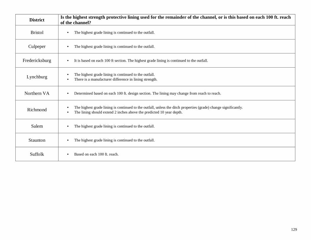
129
DistrictIs the highest strength protective lining used for the remainder of the channel, or is this based on each 100 ft. reachof the channel?
Bristol • The highest grade lining is continued to the outfall.
Culpeper • The highest grade lining is continued to the outfall.
Fredericksburg • It is based on each 100 ft section. The highest grade lining is continued to the outfall.
Lynchburg • The highest grade lining is continued to the outfall.• There is a manufacturer difference in lining strength.
Northern VA • Determined based on each 100 ft. design section. The lining may change from reach to reach.
Richmond • The highest grade lining is continued to the outfall, unless the ditch properties (grade) change significantly.• The lining should extend 2 inches above the predicted 10 year depth.
Salem • The highest grade lining is continued to the outfall.
Staunton • The highest grade lining is continued to the outfall.
Suffolk • Based on each 100 ft. reach.
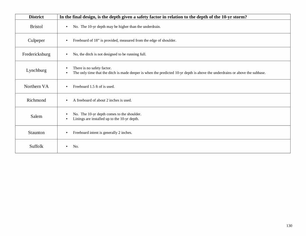
130
District In the final design, is the depth given a safety factor in relation to the depth of the 10-yr storm?
Bristol • No. The 10-yr depth may be higher than the underdrain.
Culpeper • Freeboard of 18” is provided, measured from the edge of shoulder.
Fredericksburg • No, the ditch is not designed to be running full.
Lynchburg • There is no safety factor.• The only time that the ditch is made deeper is when the predicted 10-yr depth is above the underdrains or above the subbase.
Northern VA • Freeboard 1.5 ft of is used.
Richmond • A freeboard of about 2 inches is used.
Salem • No. The 10-yr depth comes to the shoulder.• Linings are installed up to the 10-yr depth.
Staunton • Freeboard intent is generally 2 inches.
Suffolk • No.
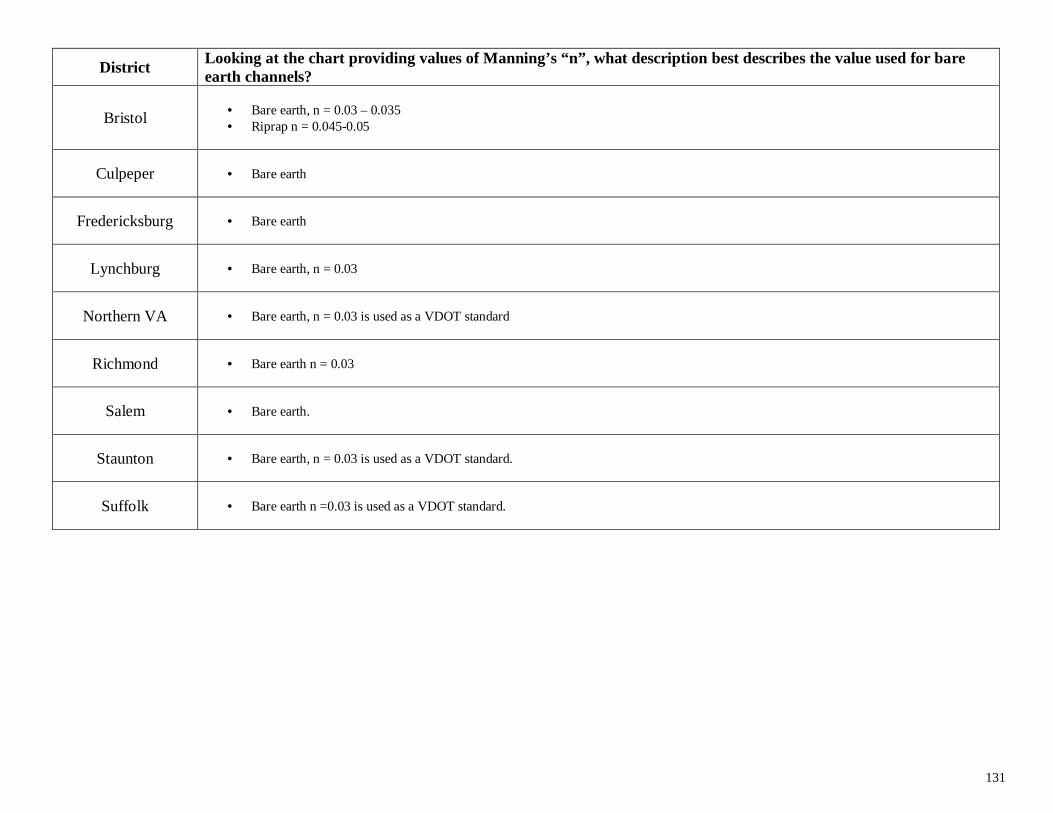
131
DistrictLooking at the chart providing values of Manning’s “n”, what description best describes the value used for bareearth channels?
Bristol • Bare earth, n = 0.03 – 0.035• Riprap n = 0.045-0.05
Culpeper • Bare earth
Fredericksburg • Bare earth
Lynchburg • Bare earth, n = 0.03
Northern VA • Bare earth, n = 0.03 is used as a VDOT standard
Richmond • Bare earth n = 0.03
Salem • Bare earth.
Staunton • Bare earth, n = 0.03 is used as a VDOT standard.
Suffolk • Bare earth n =0.03 is used as a VDOT standard.
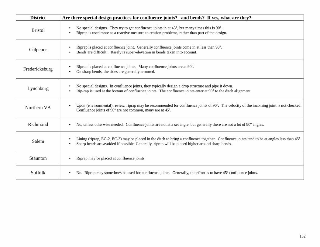
132
District Are there special design practices for confluence joints? and bends? If yes, what are they?
Bristol • No special designs. They try to get confluence joints in at 45°, but many times this is 90°.• Riprap is used more as a reactive measure to erosion problems, rather than part of the design.
Culpeper • Riprap is placed at confluence joint. Generally confluence joints come in at less than 90°.• Bends are difficult.. Rarely is super-elevation in bends taken into account.
Fredericksburg • Riprap is placed at confluence joints. Many confluence joints are at 90°.• On sharp bends, the sides are generally armored.
Lynchburg • No special designs. In confluence joints, they typically design a drop structure and pipe it down.• Rip-rap is used at the bottom of confluence joints. The confluence joints enter at 90° to the ditch alignment
Northern VA • Upon (environmental) review, riprap may be recommended for confluence joints of 90º. The velocity of the incoming joint is not checked.Confluence joints of 90º are not common, many are at 45º.
Richmond • No, unless otherwise needed. Confluence joints are not at a set angle, but generally there are not a lot of 90º angles.
Salem • Lining (riprap, EC-2, EC-3) may be placed in the ditch to bring a confluence together. Confluence joints tend to be at angles less than 45°.• Sharp bends are avoided if possible. Generally, riprap will be placed higher around sharp bends.
Staunton • Riprap may be placed at confluence joints.
Suffolk • No. Riprap may sometimes be used for confluence joints. Generally, the effort is to have 45º confluence joints.
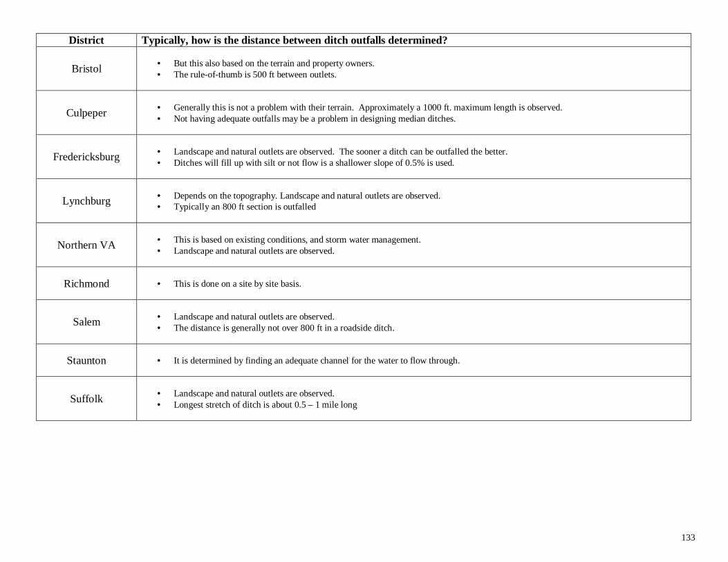
133
District Typically, how is the distance between ditch outfalls determined?
Bristol • But this also based on the terrain and property owners.• The rule-of-thumb is 500 ft between outlets.
Culpeper • Generally this is not a problem with their terrain. Approximately a 1000 ft. maximum length is observed.• Not having adequate outfalls may be a problem in designing median ditches.
Fredericksburg • Landscape and natural outlets are observed. The sooner a ditch can be outfalled the better.• Ditches will fill up with silt or not flow is a shallower slope of 0.5% is used.
Lynchburg • Depends on the topography. Landscape and natural outlets are observed.• Typically an 800 ft section is outfalled
Northern VA • This is based on existing conditions, and storm water management.• Landscape and natural outlets are observed.
Richmond • This is done on a site by site basis.
Salem • Landscape and natural outlets are observed.• The distance is generally not over 800 ft in a roadside ditch.
Staunton • It is determined by finding an adequate channel for the water to flow through.
Suffolk • Landscape and natural outlets are observed.• Longest stretch of ditch is about 0.5 – 1 mile long
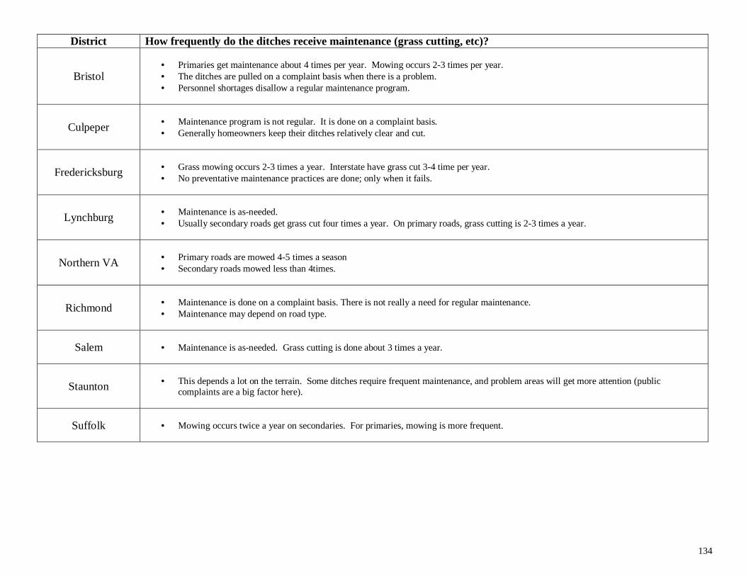
134
District How frequently do the ditches receive maintenance (grass cutting, etc)?
Bristol• Primaries get maintenance about 4 times per year. Mowing occurs 2-3 times per year.• The ditches are pulled on a complaint basis when there is a problem.• Personnel shortages disallow a regular maintenance program.
Culpeper • Maintenance program is not regular. It is done on a complaint basis.• Generally homeowners keep their ditches relatively clear and cut.
Fredericksburg • Grass mowing occurs 2-3 times a year. Interstate have grass cut 3-4 time per year.• No preventative maintenance practices are done; only when it fails.
Lynchburg • Maintenance is as-needed.• Usually secondary roads get grass cut four times a year. On primary roads, grass cutting is 2-3 times a year.
Northern VA • Primary roads are mowed 4-5 times a season• Secondary roads mowed less than 4times.
Richmond • Maintenance is done on a complaint basis. There is not really a need for regular maintenance.• Maintenance may depend on road type.
Salem • Maintenance is as-needed. Grass cutting is done about 3 times a year.
Staunton • This depends a lot on the terrain. Some ditches require frequent maintenance, and problem areas will get more attention (publiccomplaints are a big factor here).
Suffolk • Mowing occurs twice a year on secondaries. For primaries, mowing is more frequent.
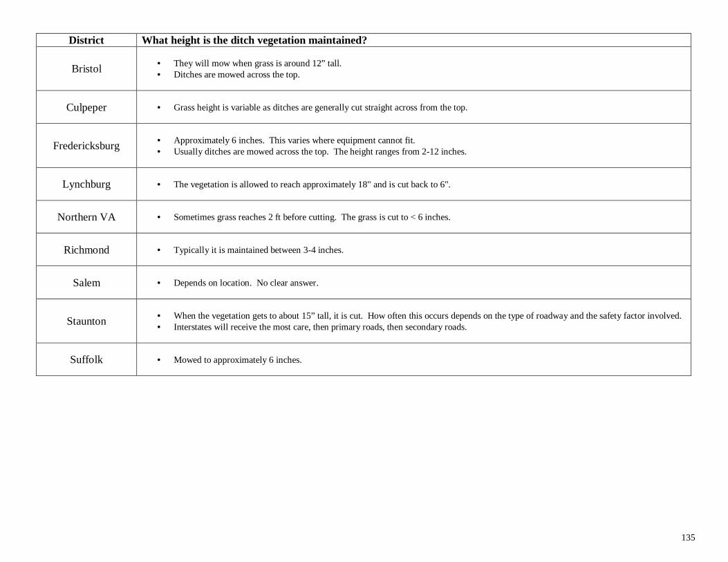
135
District What height is the ditch vegetation maintained?
Bristol • They will mow when grass is around 12” tall.• Ditches are mowed across the top.
Culpeper • Grass height is variable as ditches are generally cut straight across from the top.
Fredericksburg • Approximately 6 inches. This varies where equipment cannot fit.• Usually ditches are mowed across the top. The height ranges from 2-12 inches.
Lynchburg • The vegetation is allowed to reach approximately 18" and is cut back to 6".
Northern VA • Sometimes grass reaches 2 ft before cutting. The grass is cut to < 6 inches.
Richmond • Typically it is maintained between 3-4 inches.
Salem • Depends on location. No clear answer.
Staunton • When the vegetation gets to about 15” tall, it is cut. How often this occurs depends on the type of roadway and the safety factor involved.• Interstates will receive the most care, then primary roads, then secondary roads.
Suffolk • Mowed to approximately 6 inches.
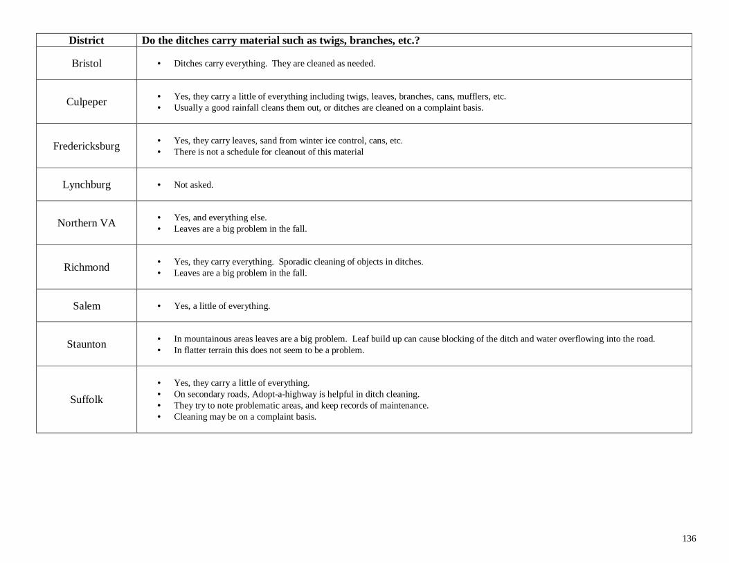
136
District Do the ditches carry material such as twigs, branches, etc.?
Bristol • Ditches carry everything. They are cleaned as needed.
Culpeper • Yes, they carry a little of everything including twigs, leaves, branches, cans, mufflers, etc.• Usually a good rainfall cleans them out, or ditches are cleaned on a complaint basis.
Fredericksburg • Yes, they carry leaves, sand from winter ice control, cans, etc.• There is not a schedule for cleanout of this material
Lynchburg • Not asked.
Northern VA • Yes, and everything else.• Leaves are a big problem in the fall.
Richmond • Yes, they carry everything. Sporadic cleaning of objects in ditches.• Leaves are a big problem in the fall.
Salem • Yes, a little of everything.
Staunton • In mountainous areas leaves are a big problem. Leaf build up can cause blocking of the ditch and water overflowing into the road.• In flatter terrain this does not seem to be a problem.
Suffolk
• Yes, they carry a little of everything.• On secondary roads, Adopt-a-highway is helpful in ditch cleaning.• They try to note problematic areas, and keep records of maintenance.• Cleaning may be on a complaint basis.
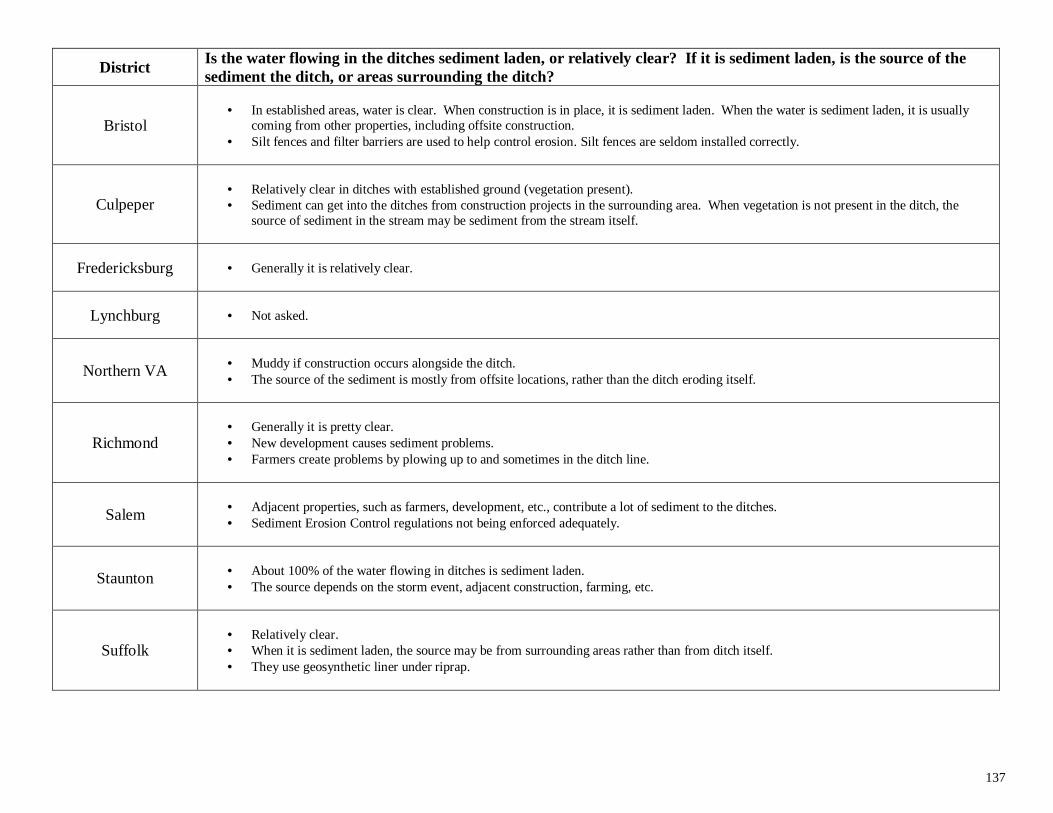
137
DistrictIs the water flowing in the ditches sediment laden, or relatively clear? If it is sediment laden, is the source of thesediment the ditch, or areas surrounding the ditch?
Bristol• In established areas, water is clear. When construction is in place, it is sediment laden. When the water is sediment laden, it is usually
coming from other properties, including offsite construction.• Silt fences and filter barriers are used to help control erosion. Silt fences are seldom installed correctly.
Culpeper• Relatively clear in ditches with established ground (vegetation present).• Sediment can get into the ditches from construction projects in the surrounding area. When vegetation is not present in the ditch, the
source of sediment in the stream may be sediment from the stream itself.
Fredericksburg • Generally it is relatively clear.
Lynchburg • Not asked.
Northern VA • Muddy if construction occurs alongside the ditch.• The source of the sediment is mostly from offsite locations, rather than the ditch eroding itself.
Richmond• Generally it is pretty clear.• New development causes sediment problems.• Farmers create problems by plowing up to and sometimes in the ditch line.
Salem • Adjacent properties, such as farmers, development, etc., contribute a lot of sediment to the ditches.• Sediment Erosion Control regulations not being enforced adequately.
Staunton • About 100% of the water flowing in ditches is sediment laden.• The source depends on the storm event, adjacent construction, farming, etc.
Suffolk• Relatively clear.• When it is sediment laden, the source may be from surrounding areas rather than from ditch itself.• They use geosynthetic liner under riprap.
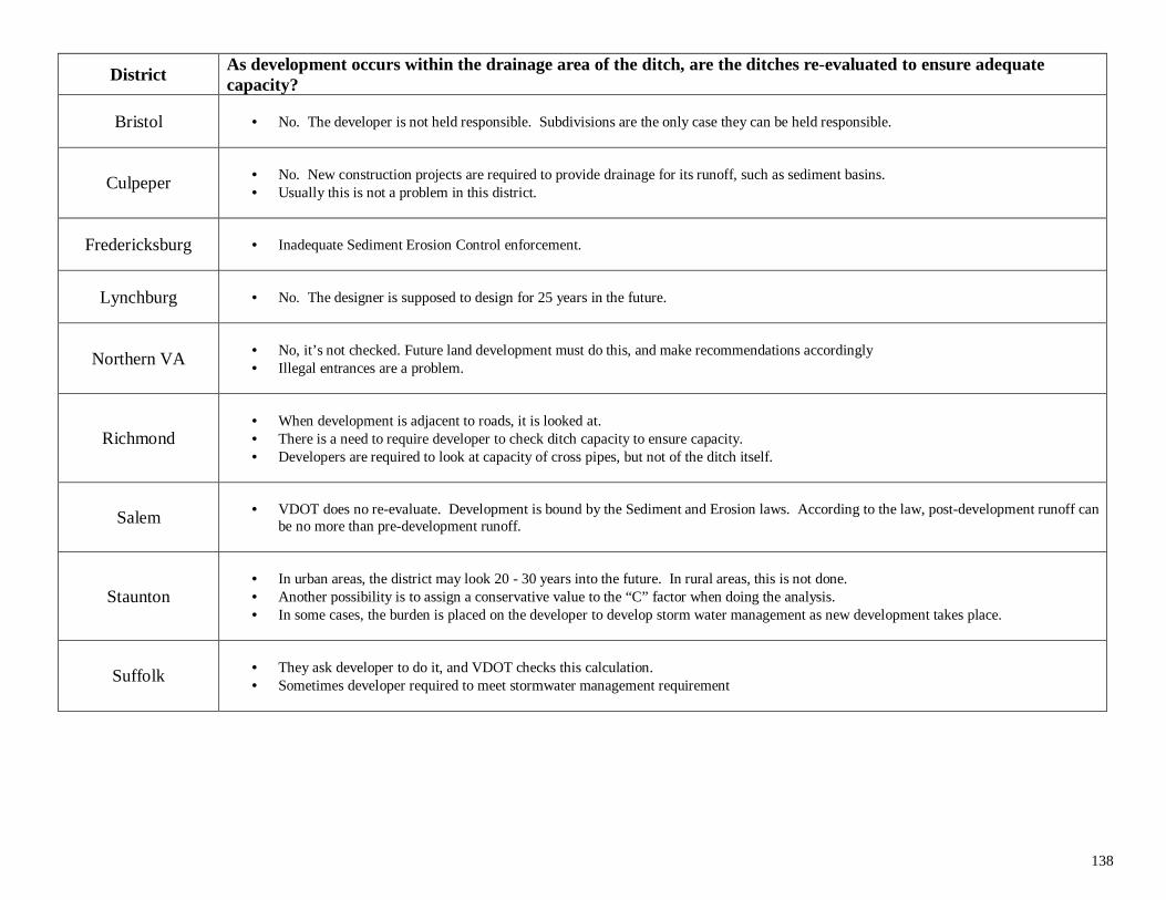
138
DistrictAs development occurs within the drainage area of the ditch, are the ditches re-evaluated to ensure adequatecapacity?
Bristol • No. The developer is not held responsible. Subdivisions are the only case they can be held responsible.
Culpeper • No. New construction projects are required to provide drainage for its runoff, such as sediment basins.• Usually this is not a problem in this district.
Fredericksburg • Inadequate Sediment Erosion Control enforcement.
Lynchburg • No. The designer is supposed to design for 25 years in the future.
Northern VA • No, it’s not checked. Future land development must do this, and make recommendations accordingly• Illegal entrances are a problem.
Richmond• When development is adjacent to roads, it is looked at.• There is a need to require developer to check ditch capacity to ensure capacity.• Developers are required to look at capacity of cross pipes, but not of the ditch itself.
Salem • VDOT does no re-evaluate. Development is bound by the Sediment and Erosion laws. According to the law, post-development runoff canbe no more than pre-development runoff.
Staunton• In urban areas, the district may look 20 - 30 years into the future. In rural areas, this is not done.• Another possibility is to assign a conservative value to the “C” factor when doing the analysis.• In some cases, the burden is placed on the developer to develop storm water management as new development takes place.
Suffolk • They ask developer to do it, and VDOT checks this calculation.• Sometimes developer required to meet stormwater management requirement
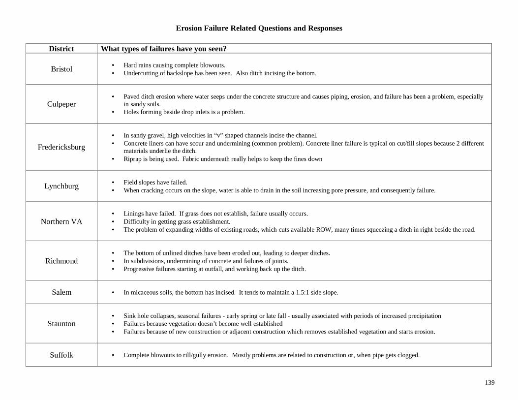
139
Erosion Failure Related Questions and Responses
District What types of failures have you seen?
Bristol • Hard rains causing complete blowouts.• Undercutting of backslope has been seen. Also ditch incising the bottom.
Culpeper• Paved ditch erosion where water seeps under the concrete structure and causes piping, erosion, and failure has been a problem, especially
in sandy soils.• Holes forming beside drop inlets is a problem.
Fredericksburg
• In sandy gravel, high velocities in “v” shaped channels incise the channel.• Concrete liners can have scour and undermining (common problem). Concrete liner failure is typical on cut/fill slopes because 2 different
materials underlie the ditch.• Riprap is being used. Fabric underneath really helps to keep the fines down
Lynchburg • Field slopes have failed.• When cracking occurs on the slope, water is able to drain in the soil increasing pore pressure, and consequently failure.
Northern VA• Linings have failed. If grass does not establish, failure usually occurs.• Difficulty in getting grass establishment.• The problem of expanding widths of existing roads, which cuts available ROW, many times squeezing a ditch in right beside the road.
Richmond• The bottom of unlined ditches have been eroded out, leading to deeper ditches.• In subdivisions, undermining of concrete and failures of joints.• Progressive failures starting at outfall, and working back up the ditch.
Salem • In micaceous soils, the bottom has incised. It tends to maintain a 1.5:1 side slope.
Staunton• Sink hole collapses, seasonal failures - early spring or late fall - usually associated with periods of increased precipitation• Failures because vegetation doesn’t become well established• Failures because of new construction or adjacent construction which removes established vegetation and starts erosion.
Suffolk • Complete blowouts to rill/gully erosion. Mostly problems are related to construction or, when pipe gets clogged.
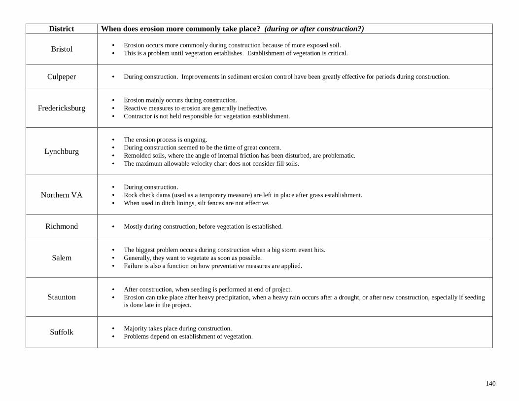
140
District When does erosion more commonly take place? (during or after construction?)
Bristol • Erosion occurs more commonly during construction because of more exposed soil.• This is a problem until vegetation establishes. Establishment of vegetation is critical.
Culpeper • During construction. Improvements in sediment erosion control have been greatly effective for periods during construction.
Fredericksburg• Erosion mainly occurs during construction.• Reactive measures to erosion are generally ineffective.• Contractor is not held responsible for vegetation establishment.
Lynchburg
• The erosion process is ongoing.• During construction seemed to be the time of great concern.• Remolded soils, where the angle of internal friction has been disturbed, are problematic.• The maximum allowable velocity chart does not consider fill soils.
Northern VA• During construction.• Rock check dams (used as a temporary measure) are left in place after grass establishment.• When used in ditch linings, silt fences are not effective.
Richmond • Mostly during construction, before vegetation is established.
Salem• The biggest problem occurs during construction when a big storm event hits.• Generally, they want to vegetate as soon as possible.• Failure is also a function on how preventative measures are applied.
Staunton• After construction, when seeding is performed at end of project.• Erosion can take place after heavy precipitation, when a heavy rain occurs after a drought, or after new construction, especially if seeding
is done late in the project.
Suffolk • Majority takes place during construction.• Problems depend on establishment of vegetation.
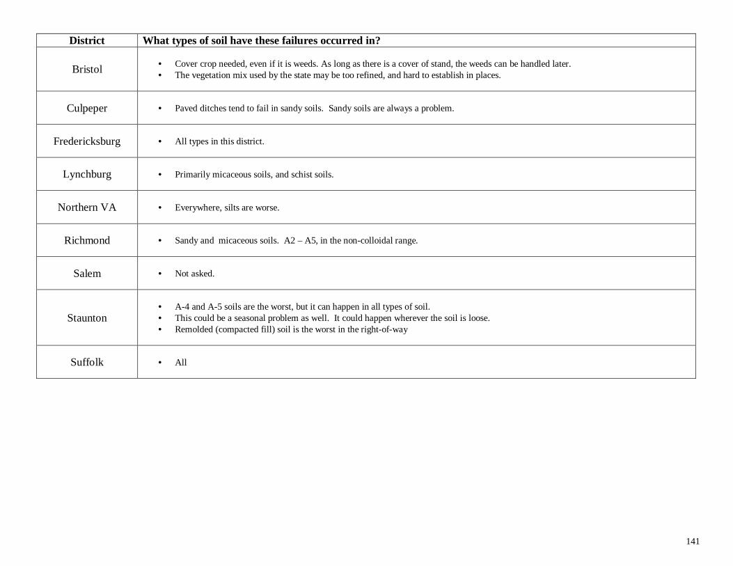
141
District What types of soil have these failures occurred in?
Bristol • Cover crop needed, even if it is weeds. As long as there is a cover of stand, the weeds can be handled later.• The vegetation mix used by the state may be too refined, and hard to establish in places.
Culpeper • Paved ditches tend to fail in sandy soils. Sandy soils are always a problem.
Fredericksburg • All types in this district.
Lynchburg • Primarily micaceous soils, and schist soils.
Northern VA • Everywhere, silts are worse.
Richmond • Sandy and micaceous soils. A2 – A5, in the non-colloidal range.
Salem • Not asked.
Staunton• A-4 and A-5 soils are the worst, but it can happen in all types of soil.• This could be a seasonal problem as well. It could happen wherever the soil is loose.• Remolded (compacted fill) soil is the worst in the right-of-way
Suffolk • All
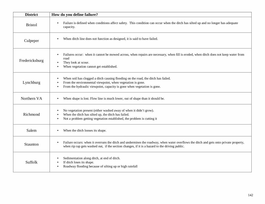
142
District How do you define failure?
Bristol • Failure is defined when conditions affect safety. This condition can occur when the ditch has silted up and no longer has adequatecapacity.
Culpeper • When ditch line does not function as designed, it is said to have failed.
Fredericksburg
• Failures occur: when it cannot be mowed across, when repairs are necessary, when fill is eroded, when ditch does not keep water fromroad
• They look at scour.• When vegetation cannot get established.
Lynchburg• When soil has clogged a ditch causing flooding on the road, the ditch has failed.• From the environmental viewpoint, when vegetation is gone.• From the hydraulic viewpoint, capacity is gone when vegetation is gone.
Northern VA • When shape is lost. Flow line is much lower, out of shape than it should be.
Richmond• No vegetation present (either washed away of when it didn’t grow).• When the ditch has silted up, the ditch has failed.• Not a problem getting vegetation established, the problem is cutting it
Salem • When the ditch looses its shape.
Staunton • Failure occurs: when it overruns the ditch and undermines the roadway, when water overflows the ditch and gets onto private property,when rip rap gets washed out, if the section changes, if it is a hazard to the driving public.
Suffolk• Sedimentation along ditch, at end of ditch.• If ditch loses its shape.• Roadway flooding because of silting up or high rainfall
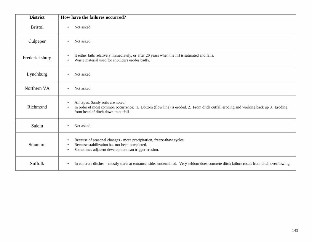
143
District How have the failures occurred?
Bristol • Not asked.
Culpeper • Not asked.
Fredericksburg • It either fails relatively immediately, or after 20 years when the fill is saturated and fails.• Waste material used for shoulders erodes badly.
Lynchburg • Not asked.
Northern VA • Not asked.
Richmond• All types. Sandy soils are noted.• In order of most common occurrence: 1. Bottom (flow line) is eroded. 2. From ditch outfall eroding and working back up 3. Eroding
from head of ditch down to outfall.
Salem • Not asked.
Staunton• Because of seasonal changes - more precipitation, freeze-thaw cycles.• Because stabilization has not been completed.• Sometimes adjacent development can trigger erosion.
Suffolk • In concrete ditches – mostly starts at entrance, sides undermined. Very seldom does concrete ditch failure result from ditch overflowing.
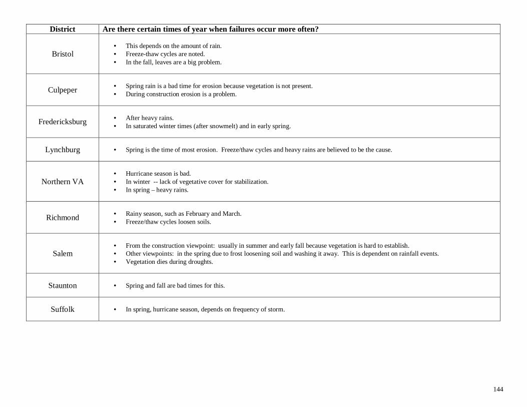
144
District Are there certain times of year when failures occur more often?
Bristol• This depends on the amount of rain.• Freeze-thaw cycles are noted.• In the fall, leaves are a big problem.
Culpeper • Spring rain is a bad time for erosion because vegetation is not present.• During construction erosion is a problem.
Fredericksburg • After heavy rains.• In saturated winter times (after snowmelt) and in early spring.
Lynchburg • Spring is the time of most erosion. Freeze/thaw cycles and heavy rains are believed to be the cause.
Northern VA• Hurricane season is bad.• In winter -- lack of vegetative cover for stabilization.• In spring – heavy rains.
Richmond • Rainy season, such as February and March.• Freeze/thaw cycles loosen soils.
Salem• From the construction viewpoint: usually in summer and early fall because vegetation is hard to establish.• Other viewpoints: in the spring due to frost loosening soil and washing it away. This is dependent on rainfall events.• Vegetation dies during droughts.
Staunton • Spring and fall are bad times for this.
Suffolk • In spring, hurricane season, depends on frequency of storm.
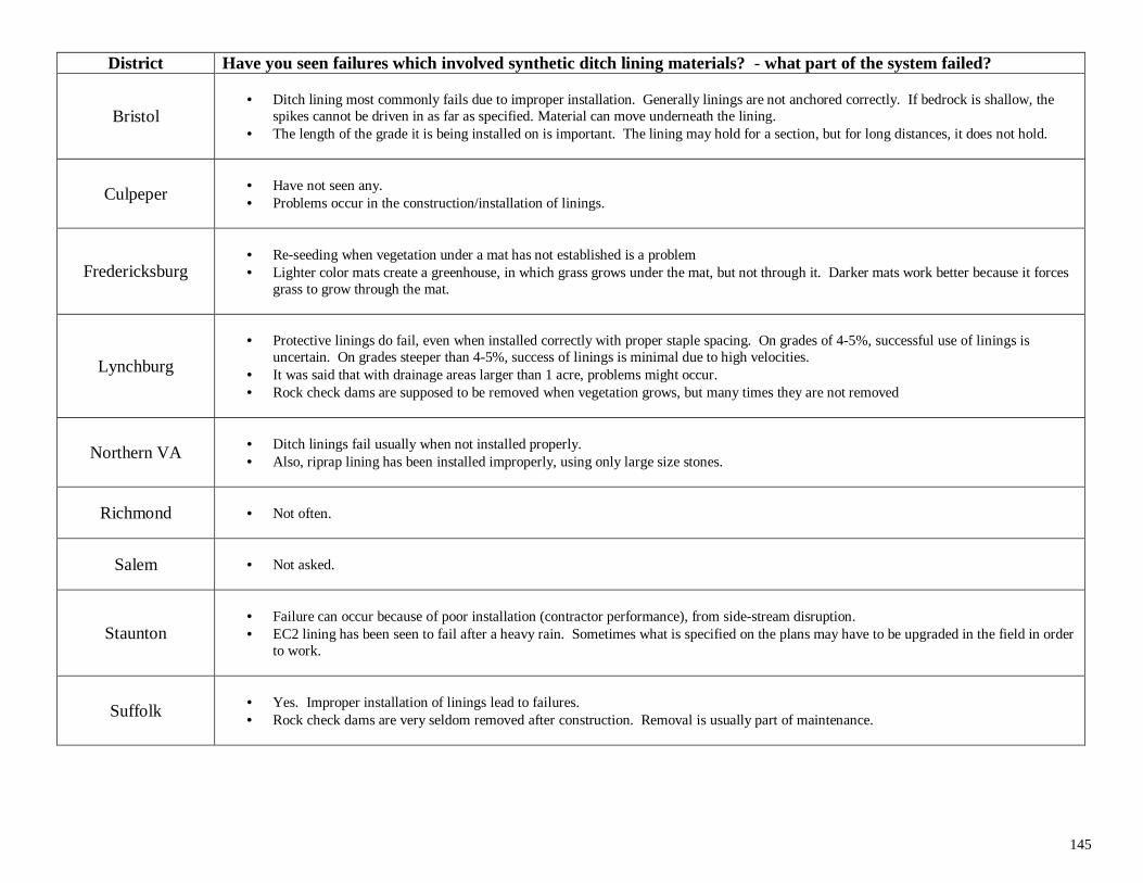
145
District Have you seen failures which involved synthetic ditch lining materials? - what part of the system failed?
Bristol• Ditch lining most commonly fails due to improper installation. Generally linings are not anchored correctly. If bedrock is shallow, the
spikes cannot be driven in as far as specified. Material can move underneath the lining.• The length of the grade it is being installed on is important. The lining may hold for a section, but for long distances, it does not hold.
Culpeper • Have not seen any.• Problems occur in the construction/installation of linings.
Fredericksburg• Re-seeding when vegetation under a mat has not established is a problem• Lighter color mats create a greenhouse, in which grass grows under the mat, but not through it. Darker mats work better because it forces
grass to grow through the mat.
Lynchburg
• Protective linings do fail, even when installed correctly with proper staple spacing. On grades of 4-5%, successful use of linings isuncertain. On grades steeper than 4-5%, success of linings is minimal due to high velocities.
• It was said that with drainage areas larger than 1 acre, problems might occur.• Rock check dams are supposed to be removed when vegetation grows, but many times they are not removed
Northern VA • Ditch linings fail usually when not installed properly.• Also, riprap lining has been installed improperly, using only large size stones.
Richmond • Not often.
Salem • Not asked.
Staunton• Failure can occur because of poor installation (contractor performance), from side-stream disruption.• EC2 lining has been seen to fail after a heavy rain. Sometimes what is specified on the plans may have to be upgraded in the field in order
to work.
Suffolk • Yes. Improper installation of linings lead to failures.• Rock check dams are very seldom removed after construction. Removal is usually part of maintenance.
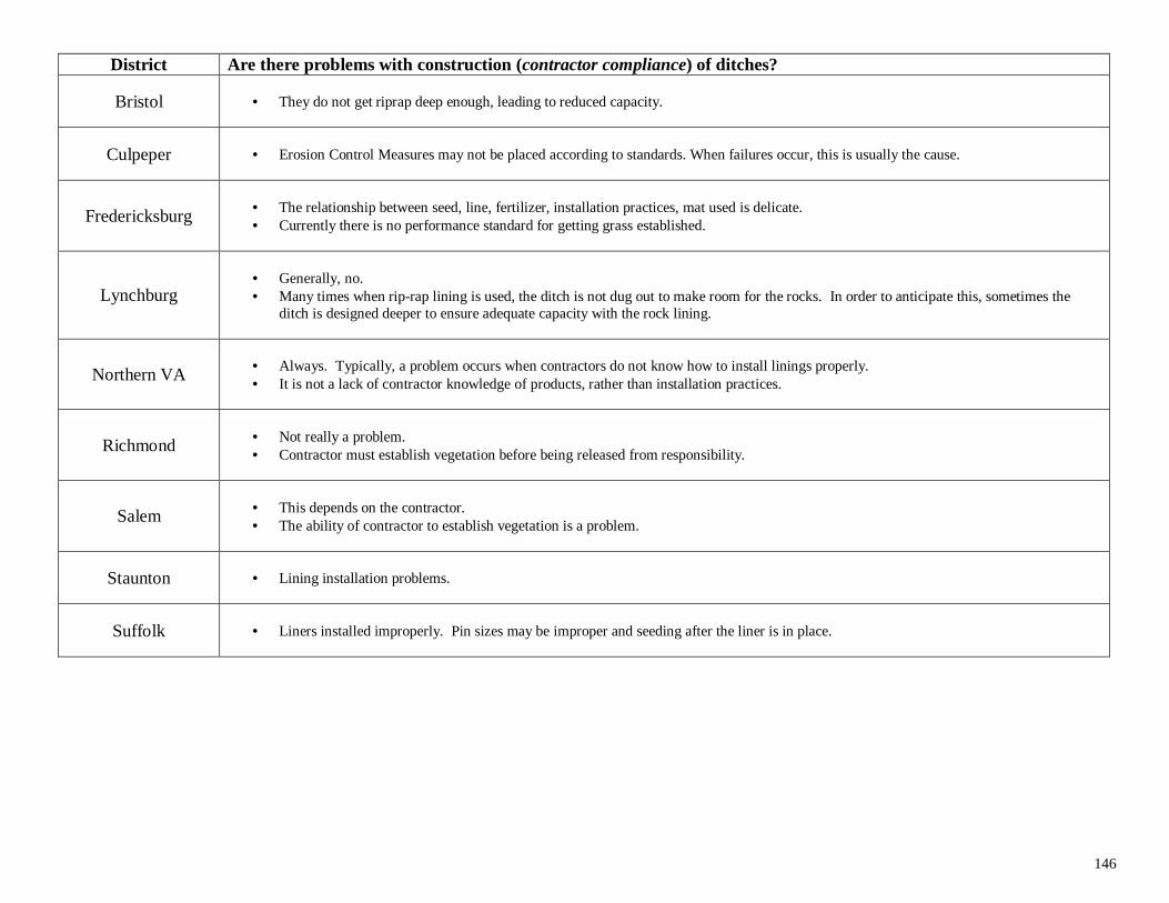
146
District Are there problems with construction (contractor compliance) of ditches?
Bristol • They do not get riprap deep enough, leading to reduced capacity.
Culpeper • Erosion Control Measures may not be placed according to standards. When failures occur, this is usually the cause.
Fredericksburg • The relationship between seed, line, fertilizer, installation practices, mat used is delicate.• Currently there is no performance standard for getting grass established.
Lynchburg• Generally, no.• Many times when rip-rap lining is used, the ditch is not dug out to make room for the rocks. In order to anticipate this, sometimes the
ditch is designed deeper to ensure adequate capacity with the rock lining.
Northern VA • Always. Typically, a problem occurs when contractors do not know how to install linings properly.• It is not a lack of contractor knowledge of products, rather than installation practices.
Richmond • Not really a problem.• Contractor must establish vegetation before being released from responsibility.
Salem • This depends on the contractor.• The ability of contractor to establish vegetation is a problem.
Staunton • Lining installation problems.
Suffolk • Liners installed improperly. Pin sizes may be improper and seeding after the liner is in place.
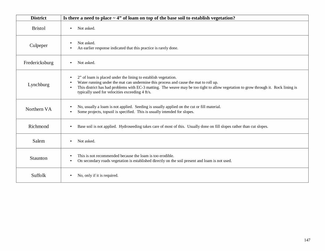
147
District Is there a need to place ~ 4” of loam on top of the base soil to establish vegetation?
Bristol • Not asked.
Culpeper • Not asked.• An earlier response indicated that this practice is rarely done.
Fredericksburg • Not asked.
Lynchburg
• 2” of loam is placed under the lining to establish vegetation.• Water running under the mat can undermine this process and cause the mat to roll up.• This district has had problems with EC-3 matting. The weave may be too tight to allow vegetation to grow through it. Rock lining is
typically used for velocities exceeding 4 ft/s.
Northern VA • No, usually a loam is not applied. Seeding is usually applied on the cut or fill material.• Some projects, topsoil is specified. This is usually intended for slopes.
Richmond • Base soil is not applied. Hydroseeding takes care of most of this. Usually done on fill slopes rather than cut slopes.
Salem • Not asked.
Staunton • This is not recommended because the loam is too erodible.• On secondary roads vegetation is established directly on the soil present and loam is not used.
Suffolk • No, only if it is required.
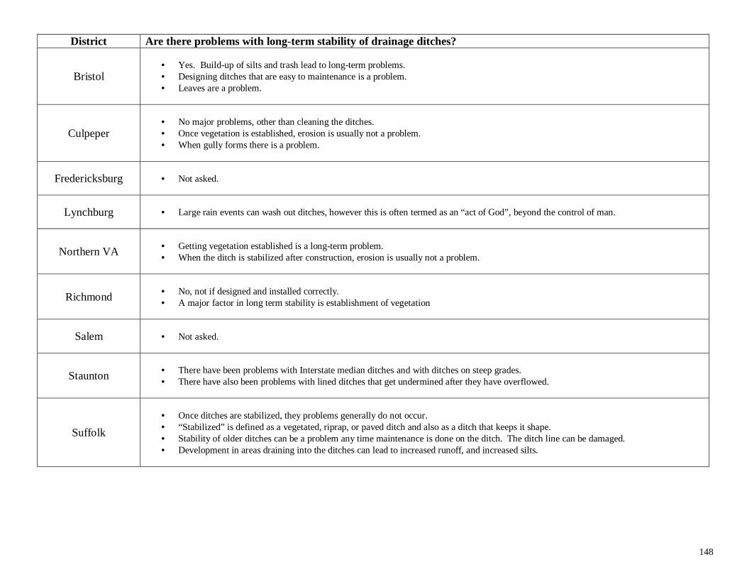
148
District Are there problems with long-term stability of drainage ditches?
Bristol• Yes. Build-up of silts and trash lead to long-term problems.• Designing ditches that are easy to maintenance is a problem.• Leaves are a problem.
Culpeper• No major problems, other than cleaning the ditches.• Once vegetation is established, erosion is usually not a problem.• When gully forms there is a problem.
Fredericksburg • Not asked.
Lynchburg • Large rain events can wash out ditches, however this is often termed as an “act of God”, beyond the control of man.
Northern VA • Getting vegetation established is a long-term problem.• When the ditch is stabilized after construction, erosion is usually not a problem.
Richmond • No, not if designed and installed correctly.• A major factor in long term stability is establishment of vegetation
Salem • Not asked.
Staunton • There have been problems with Interstate median ditches and with ditches on steep grades.• There have also been problems with lined ditches that get undermined after they have overflowed.
Suffolk
• Once ditches are stabilized, they problems generally do not occur.• “Stabilized” is defined as a vegetated, riprap, or paved ditch and also as a ditch that keeps it shape.• Stability of older ditches can be a problem any time maintenance is done on the ditch. The ditch line can be damaged.• Development in areas draining into the ditches can lead to increased runoff, and increased silts.
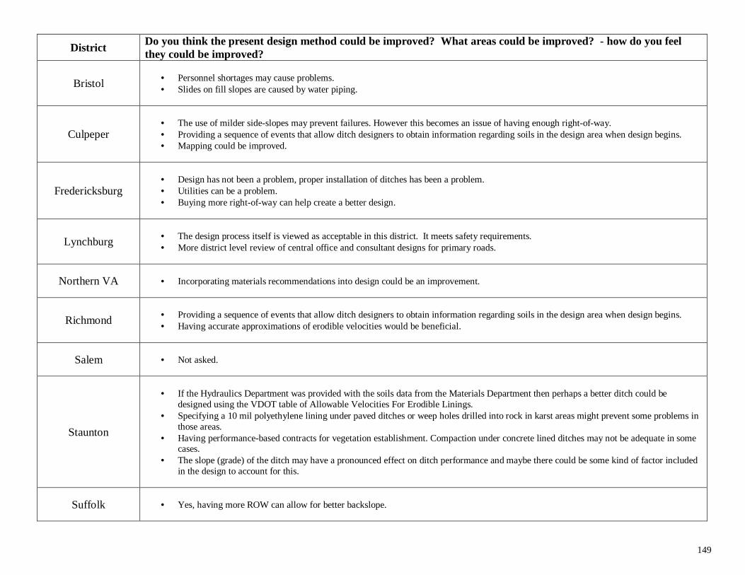
149
DistrictDo you think the present design method could be improved? What areas could be improved? - how do you feelthey could be improved?
Bristol • Personnel shortages may cause problems.• Slides on fill slopes are caused by water piping.
Culpeper• The use of milder side-slopes may prevent failures. However this becomes an issue of having enough right-of-way.• Providing a sequence of events that allow ditch designers to obtain information regarding soils in the design area when design begins.• Mapping could be improved.
Fredericksburg• Design has not been a problem, proper installation of ditches has been a problem.• Utilities can be a problem.• Buying more right-of-way can help create a better design.
Lynchburg • The design process itself is viewed as acceptable in this district. It meets safety requirements.• More district level review of central office and consultant designs for primary roads.
Northern VA • Incorporating materials recommendations into design could be an improvement.
Richmond • Providing a sequence of events that allow ditch designers to obtain information regarding soils in the design area when design begins.• Having accurate approximations of erodible velocities would be beneficial.
Salem • Not asked.
Staunton
• If the Hydraulics Department was provided with the soils data from the Materials Department then perhaps a better ditch could bedesigned using the VDOT table of Allowable Velocities For Erodible Linings.
• Specifying a 10 mil polyethylene lining under paved ditches or weep holes drilled into rock in karst areas might prevent some problems inthose areas.
• Having performance-based contracts for vegetation establishment. Compaction under concrete lined ditches may not be adequate in somecases.
• The slope (grade) of the ditch may have a pronounced effect on ditch performance and maybe there could be some kind of factor includedin the design to account for this.
Suffolk • Yes, having more ROW can allow for better backslope.
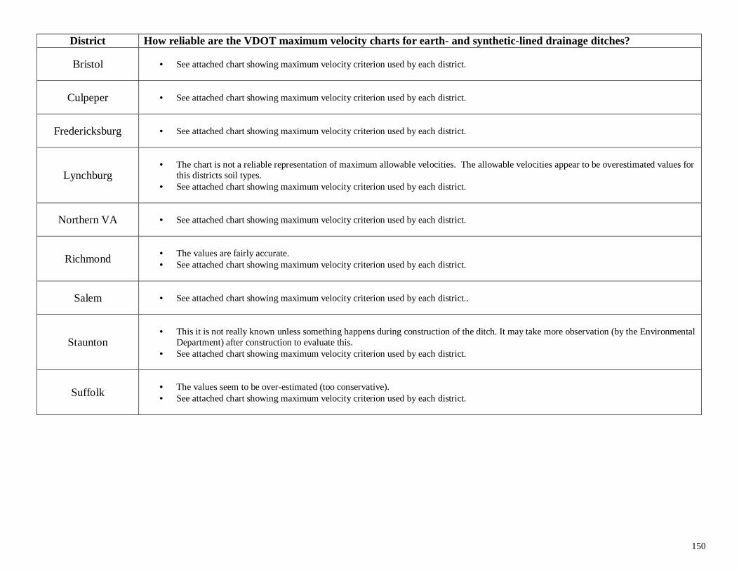
150
District How reliable are the VDOT maximum velocity charts for earth- and synthetic-lined drainage ditches?
Bristol • See attached chart showing maximum velocity criterion used by each district.
Culpeper • See attached chart showing maximum velocity criterion used by each district.
Fredericksburg • See attached chart showing maximum velocity criterion used by each district.
Lynchburg• The chart is not a reliable representation of maximum allowable velocities. The allowable velocities appear to be overestimated values for
this districts soil types.• See attached chart showing maximum velocity criterion used by each district.
Northern VA • See attached chart showing maximum velocity criterion used by each district.
Richmond • The values are fairly accurate.• See attached chart showing maximum velocity criterion used by each district.
Salem • See attached chart showing maximum velocity criterion used by each district..
Staunton• This it is not really known unless something happens during construction of the ditch. It may take more observation (by the Environmental
Department) after construction to evaluate this.• See attached chart showing maximum velocity criterion used by each district.
Suffolk • The values seem to be over-estimated (too conservative).• See attached chart showing maximum velocity criterion used by each district.
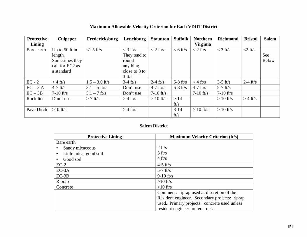
151
Maximum Allowable Velocity Criterion for Each VDOT District
ProtectiveLining
Culpeper Fredericksburg Lynchburg Staunton Suffolk NorthernVirginia
Richmond Bristol Salem
Bare earth Up to 50 ft inlength.Sometimes theycall for EC2 asa standard
<1.5 ft/s < 3 ft/sThey tend toroundanythingclose to 3 to3 ft/s
< 2 ft/s < 6 ft/s < 2 ft/s < 3 ft/s <2 ft/sSeeBelow
EC - 2 < 4 ft/s 1.5 – 3.0 ft/s 3-4 ft/s 2-4 ft/s 6-8 ft/s < 4 ft/s 3-5 ft/s 2-4 ft/sEC – 3 A 4-7 ft/s 3.1 – 5 ft/s Don’t use 4-7 ft/s 6-8 ft/s 4-7 ft/s 5-7 ft/sEC – 3B 7-10 ft/s 5.1 – 7 ft/s Don’t use 7-10 ft/s 7-10 ft/s 7-10 ft/sRock line Don’t use > 7 ft/s > 4 ft/s > 10 ft/s > 14
ft/s> 10 ft/s > 4 ft/s
Pave Ditch >10 ft/s > 4 ft/s 8-14ft/s
> 10 ft/s > 10 ft/s
Salem District
Protective Lining Maximum Velocity Criterion (ft/s)Bare earth• Sandy micaceous• Little mica, good soil• Good soil
2 ft/s3 ft/s4 ft/s
EC-2 4-5 ft/sEC-3A 5-7 ft/sEC-3B 9-10 ft/sRiprap >10 ft/sConcrete >10 ft/s
Comment: riprap used at discretion of theResident engineer. Secondary projects: riprapused. Primary projects: concrete used unlessresident engineer prefers rock
153
APPENDIX B. SUMMARIES OF EACH VDOT DISTRICT VISIT
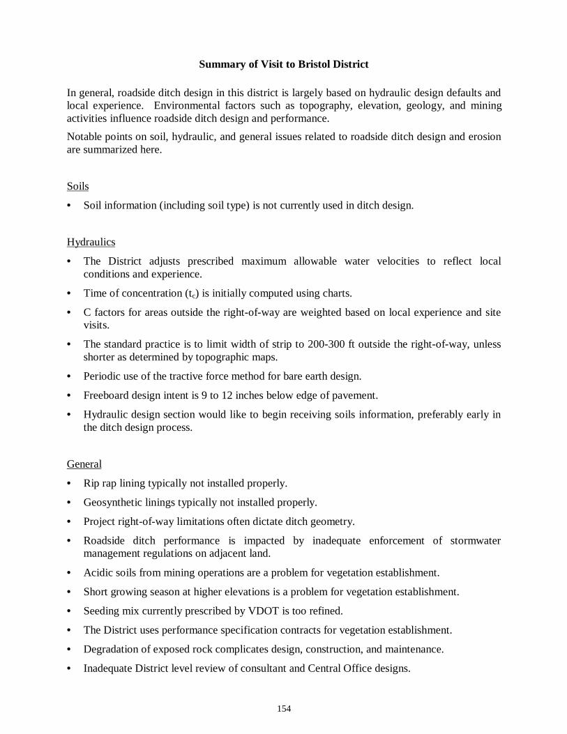
154
Summary of Visit to Bristol District
In general, roadside ditch design in this district is largely based on hydraulic design defaults andlocal experience. Environmental factors such as topography, elevation, geology, and miningactivities influence roadside ditch design and performance.
Notable points on soil, hydraulic, and general issues related to roadside ditch design and erosionare summarized here.
Soils
• Soil information (including soil type) is not currently used in ditch design.
Hydraulics
• The District adjusts prescribed maximum allowable water velocities to reflect localconditions and experience.
• Time of concentration (tc) is initially computed using charts.
• C factors for areas outside the right-of-way are weighted based on local experience and sitevisits.
• The standard practice is to limit width of strip to 200-300 ft outside the right-of-way, unlessshorter as determined by topographic maps.
• Periodic use of the tractive force method for bare earth design.
• Freeboard design intent is 9 to 12 inches below edge of pavement.
• Hydraulic design section would like to begin receiving soils information, preferably early inthe ditch design process.
General
• Rip rap lining typically not installed properly.
• Geosynthetic linings typically not installed properly.
• Project right-of-way limitations often dictate ditch geometry.
• Roadside ditch performance is impacted by inadequate enforcement of stormwatermanagement regulations on adjacent land.
• Acidic soils from mining operations are a problem for vegetation establishment.
• Short growing season at higher elevations is a problem for vegetation establishment.
• Seeding mix currently prescribed by VDOT is too refined.
• The District uses performance specification contracts for vegetation establishment.
• Degradation of exposed rock complicates design, construction, and maintenance.
• Inadequate District level review of consultant and Central Office designs.
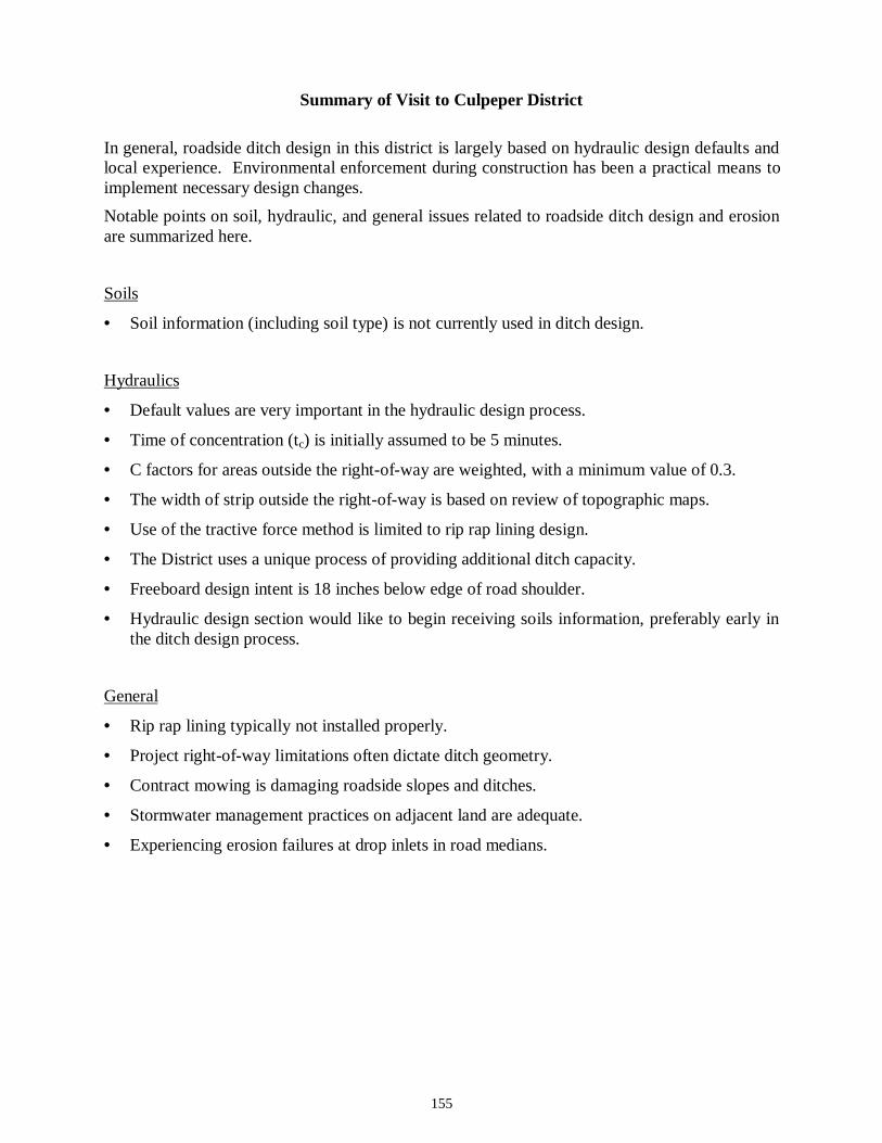
155
Summary of Visit to Culpeper District
In general, roadside ditch design in this district is largely based on hydraulic design defaults andlocal experience. Environmental enforcement during construction has been a practical means toimplement necessary design changes.
Notable points on soil, hydraulic, and general issues related to roadside ditch design and erosionare summarized here.
Soils
• Soil information (including soil type) is not currently used in ditch design.
Hydraulics
• Default values are very important in the hydraulic design process.
• Time of concentration (tc) is initially assumed to be 5 minutes.
• C factors for areas outside the right-of-way are weighted, with a minimum value of 0.3.
• The width of strip outside the right-of-way is based on review of topographic maps.
• Use of the tractive force method is limited to rip rap lining design.
• The District uses a unique process of providing additional ditch capacity.
• Freeboard design intent is 18 inches below edge of road shoulder.
• Hydraulic design section would like to begin receiving soils information, preferably early inthe ditch design process.
General
• Rip rap lining typically not installed properly.
• Project right-of-way limitations often dictate ditch geometry.
• Contract mowing is damaging roadside slopes and ditches.
• Stormwater management practices on adjacent land are adequate.
• Experiencing erosion failures at drop inlets in road medians.
156
Summary of Visit to Fredericksburg District
In general, roadside ditch design in this district is based on site-specific (soil) information andhydraulic design. Local experience and environmental enforcement during construction havebeen a practical means to implement necessary design changes to account for frequent changes insoil type. Environmental factors (acidic soils and tidal fluctuations) and adjacent landdevelopment influence roadside ditch design and performance.
Notable points on soil, hydraulic, and general issues related to roadside ditch design and erosionare summarized here.
Soils
• The District is characterized by frequent changes in soil type.
• Minimal soil information gathered along roadway projects.
• Soil type is incorporated in ditch design through site visits, review of Soil ConservationService maps, and local experience.
• A bulk soil sample was collected from an on-going erosion feature in this District, processedfor laboratory soil classification tests, and classified as an A-2-4 soil.
Hydraulics
• The District adjusts prescribed maximum allowable water velocities to reflect localconditions and experience.
• C factors for areas outside the right-of-way are weighted, and range between 0.2-0.3.
• The standard practice to determine width of strip outside the right-of-way is based on fieldinspection.
• Use of the tractive force method is limited to rip rap lining design.
• Freeboard design intent is not clear.
General
• Project right-of-way limitations often dictate ditch geometry.
• Roadside ditch performance is impacted by inadequate enforcement of stormwatermanagement regulations on adjacent land.
• Acidic soil from parent rock decomposition is a problem for vegetation establishment.
• Tidal fluctuations result in ditch side-slope failures.
• Presence of buried utilities along ditch line limits allowable ditch depth.
• Erosion repairs during construction are generally ineffective, soil fill placed in failed ditchends up being eroded.
• New road superelevation design is increasing runoff velocity and flow in ditches.
• Geosynthetic lining color may impact grass establishment and lining performance.
157
Summary of Visit to Lynchburg District
In general, roadside ditch design in this district is largely based on hydraulic design, but doesinclude checks against site-specific (soil) information. The Materials section provides soil typeanticipated at final ditch line along roadway alignment. Timely reporting of this information bythe Materials section to the Hydraulic section would benefit the ditch design process.
Notable points on soil, hydraulic, and general issues related to roadside ditch design and erosionare summarized here.
Soils
• The Materials section provides recommended soil types (anticipated along the ditch line) asreferenced in the Allowable Velocities for Erodible Linings table.
• Soil survey report arrives at Hydraulic section after substantial completion of ditch design.
• A bulk soil sample was collected from an on-going erosion feature in this District, processedfor laboratory soil classification tests, and classified as an A-7-6 soil.
Hydraulics
• The District adjusts prescribed maximum allowable water velocities to reflect localconditions and experience.
• Time of concentration (tc) is initially assumed to be 5 minutes.
• C factors for areas outside the right-of-way are weighted, and normally comes up to 0.35.
• The width of strip outside the right-of-way is based on review of topographic maps.
• The approximated 10-yr. flow depth coincides with the road shoulder.
• Materials section recommends ditch side-slopes.
• Hydraulic section would like soil information earlier in design process.
General
• Rip rap lining typically not installed properly.
• Project right-of-way limitations often dictate ditch geometry.
• Inadequate District level review of consultant and Central Office designs.
• Severe erosion failures in Danville area.
158
Summary of Visit to Northern Virginia District
In general, District personnel do not perform roadside ditch design. Recommendations for ditchrepairs and upgrades are generated by District personnel, and are largely based on hydraulicdesign and local experience. Large roadway structures and limited right-of- way impacts ditchdesign and performance.
Notable points on soil, hydraulic, and general issues related to roadside ditch design and erosionare summarized here.
Soils
• Soil information (including soil type) is not currently used in ditch design.
• A bulk soil sample was collected from an on-going erosion feature in this District, processedfor laboratory soil classification tests, and classified as an A-1-b soil.
Hydraulics
• C factors for areas outside the right-of-way are weighted.
• The width of strip outside the right-of-way is based on review of topographic maps.
• Freeboard design intent is 18 inches below edge of road shoulder.
• Use of the tractive force method is limited to rip rap lining design.
General
• Rip rap lining typically not installed properly.
• Inadequate District level review of consultant and Central Office designs.
• Evolving roadways and fixed right-of-way result in increased flows and decreased ditchcapacity.
• Larger roadway structures unique to this District result in significant runoff volumes.
• Current contract practices release contractors prior to sufficient vegetation establishment.
• Roadside ditch performance is impacted by inadequate enforcement of stormwatermanagement regulations on adjacent land.
• Silt fences may not perform their intended function adequately when used in the ditch line.
• Utility placement in the ditch line may impact ditch function.
• Unique application of protective ditch linings.
159
Summary of Visit to Richmond District
In general, roadside ditch design in this district is largely based on hydraulic design defaults andlocal experience. Roadside ditch erosion is reportedly not a significant problem in this District.
Notable points on soil, hydraulic, and general issues related to roadside ditch design and erosionare summarized here.
Soils
• The District is characterized by frequent changes in soil type (east of I-95).
• Soil types are incorporated in ditch design through local experience.
• Soil field data may be used in ditch design, if soil survey report is available at the time ofdesign.
Hydraulics
• Time of concentration (tc) is initially computed using charts.
• C factors for areas outside the right-of-way are weighted, and based on aerial photos or sitevisits.
• The width of strip outside the right-of-way is based on review of topographic maps.
• Freeboard design intent is at least 2 inches above predicted 10-yr. depth.
General
• Roadside ditch performance is impacted by inadequate enforcement of stormwatermanagement regulations on adjacent land.
• Periodic maintenance is a problem due to personnel shortages.
• The District uses performance specification contracts for vegetation establishment.
160
Summary of Visit to Salem District
In general, roadside ditch design in this district is largely based on undocumented localexperience. Environmental enforcement during construction has been a practical means toimplement necessary design changes.
Notable points on soil, hydraulic, and general issues related to roadside ditch design and erosionare summarized here.
Soils
• Minimal soil information is gathered for ditch design.
• Soil types are incorporated in ditch design through site visits and local experience.
Hydraulics
• A great deal of undocumented local experience is used in the design process.
• The District adjusts prescribed maximum allowable water velocities to reflect localconditions and experience.
• Time of concentration (tc) is initially computed using charts.
• C factors for areas outside the right-of-way are weighted, based on site visits.
• The standard practice is to define drainage areas outside the right-of-way using topographicmaps and aerial photos.
• The approximated 10-yr. flow depth coincides with the road shoulder.
• The first segment of the ditch analyzed is arbitrarily selected.
General
• Rip rap lining typically not installed properly.
• Rip rap is readily accessible and cheap in the District.
• Inadequate District level review of consultant and Central Office designs.
• Roadside ditch performance is impacted by inadequate enforcement of stormwatermanagement regulations on adjacent land.
• Frequent changes in manufacturer's installation procedures for geosynthetic linings makeenforcement difficult.
• Short growing season at higher elevations is a problem for vegetation establishment.
• Seeding mix currently prescribed by VDOT is too refined.
• Phased seeding is recommended.
• Erosion repairs during construction are generally ineffective.
161
Summary of Visit to Staunton District
In general, roadside ditch design in this district is largely based on hydraulic design, but doesinclude checks against site-specific (soil) information. The Materials section gathers significantsoil information along a roadway alignment. Timely reporting of this information by theMaterials section to the Hydraulic section would benefit the ditch design process.
Notable points on soil, hydraulic, and general issues related to roadside ditch design and erosionare summarized here.
Soils
• Significant soils information gathered and reported by Materials section.
• Soil field data is not currently used in ditch design.
• Soil types are incorporated in ditch design using Soil Conservation Service maps and localexperience.
Hydraulics
• C factors for areas outside the right-of-way are weighted, and based on topographic maps andaerial photos.
• The width of strip outside the right-of-way is based on review of USGS and District maps.
• Freeboard design intent is 12 inches below edge of road shoulder.
• Use of the tractive force method is limited to rip rap lining design.
• Default maximum allowable water velocity of 3 fps is used for ditch design in the absence ofsoil information.
General
• Inadequate District level review of consultant and Central Office designs.
• Consultant designs result in large burden on District personnel to make corrective fieldmeasures.
• District is considering the use of performance specification contracts for vegetationestablishment.
• Timing of contract awards can affect vegetation establishment at the end of construction.
• Materials section is developing a system that would overlay soils information on projectplans.
• Karst terrain poses specific problems in ditch design.
162
Summary of Visit to Suffolk District
In general, roadside ditch design in this district is largely based on hydraulic design defaults andlocal experience. Roadside ditch performance has been impacted by activities (e.g., farming andlogging) on adjacent land. Enforcement of stormwater management regulations has also been aproblem.
Notable points on soil, hydraulic, and general issues related to roadside ditch design and erosionare summarized here.
Soils
• Soil types are incorporated in ditch design through sites visits and local experience.
• Two bulk soil samples were collected from on-going erosion features in this District,processed for laboratory soil classification tests, and classified as A-3 soils.
Hydraulics
• The District adjusts prescribed maximum allowable water velocities to reflect localconditions and experience.
• Time of concentration (tc) is initially computed using charts.
• C factors for areas outside the right-of-way are weighted; typical value is 0.4.
• Periodic use of the tractive force method for bare earth design.
• A standard value of 100 ft is used for the width of strip outside the right-of-way.
• The approximated 10-yr. flow depth coincides with the road shoulder.
General
• Project right-of-way limitations often dictate ditch geometry.
• Geosynthetic linings typically not installed properly.
• The District uses performance specification contracts for vegetation establishment.
• Roadside ditch performance is impacted by inadequate enforcement of stormwatermanagement regulations on adjacent land.
• Roadside ditch performance is impacted by adjacent land activities (e.g., farming andlogging).
• Utility placement in the ditch line may impact ditch function.
• Tidal fluctuations are not accounted for in ditch design.
163
VITA
Sheila Lynne Stallings was born the third child to John and Judy Stallings of Hopewell,
VA. Born and raised in Hopewell, VA, Sheila graduated from Hopewell High School in 1994.
She began her undergraduate studies at the University of Virginia. After three semesters at
UVA, Sheila transferred to Virginia Tech, where she completed her undergraduate degree, cum
laude, in Civil Engineering in 1998. In April 1998 Sheila was EIT certified in Virginia.
Immediately after completing her undergraduate degree, she began her graduate studies at
Virginia Tech in the Hydrosystems Division. As a graduate student, Sheila was a recipient of a
Pratt Fellowship. Upon completing her Masters degree in Civil Engineering in September 1999,
Sheila will assume a position of Water Resources Engineer with Dewberry and Davis in Raleigh,
NC.