Embed Size (px)
Citation preview
66th International Astronautical Congress, Jerusalem, Israel. Copyright ©2015 by the International Astronautical Federation. All rights reserved.
IAC-15- C2.9.3 Page 1 of 9
IAC-15- C2.9.3
MATERIALS CHARACTERIZATION OF ADDITIVELY MANUFACTURED COMPONENTS FOR
ROCKET PROPULSION
Robert Carter
National Aeronautics and Space Administration, Glenn Research Center, U.S.A., [email protected]
Susan Draper, Ivan Locci, Bradley Lerch, David Ellis, Paul Senick, Michael Meyer, James Free
National Aeronautics and Space Administration, Glenn Research Center, U.S.A.
Ken Cooper, Zachary Jones
National Aeronautics and Space Administration, Marshall Space Flight Center, U.S.A.
To advance Additive Manufacturing (AM) technologies for production of rocket propulsion components the NASA
Glenn Research Center (GRC) is applying state of the art characterization techniques to interrogate microstructure and
mechanical properties of AM materials and components at various steps in their processing. The materials being
investigated for upper stage rocket engines include titanium, copper, and nickel alloys. Additive manufacturing
processes include laser powder bed, electron beam powder bed, and electron beam wire fed processes. Various post
build thermal treatments, including Hot Isostatic Pressure (HIP), have been studied to understand their influence on
microstructure, mechanical properties, and build density. Micro-computed tomography, electron microscopy, and
mechanical testing in relevant temperature environments has been performed to develop relationships between build
quality, microstructure, and mechanical performance at temperature. A summary of GRC’s Additive Manufacturing
roles and experimental findings will be presented.
I. INTRODUCTION
Additive Manufacturing (AM) is revolutionizing the
design and manufacture of rocket engines. Incremental
deposition of material, layer-by-layer, using AM allows
for new designs that are unattainable using conventional
subtractive machining techniques. Additionally, AM
enables rapid and inexpensive production of high fidelity
hardware prototypes. This permits more efficient testing
and iteration of design solutions to achieve desired
performance characteristics.
Recently AM processes have achieved a level of
maturity where they are capable of producing metallic
flight quality hardware components. The leading
technology in this area is Powder Bed Fusion (PBF)
where metallic powder is selectively fused layer by layer
using either an electron beam in Electron Beam Melting
(EBM), or laser beam in Laser Beam Melting (LBM).
Multiple factors can affect the properties of metallic
components produced using PBF. These include powder
feedstock chemistry and morphology, processing
parameters used during the build, and post processing
thermal processes. Researchers at the NASA Glenn
Research Center (GRC) are interrogating the
microstructure and mechanical properties of components
produced using PBF. The results of studies conducted on
titanium alloy Ti-6Al-4V for an RL10 rocket engine
component and on copper alloy GRCop-84 for a low cost
upper stage rocket engine are covered in detail. Hot fire
testing performed at GRC is also discussed.
II. GRC AND ADDITIVE MANUFACTURING
GRC has an extensive heritage in the research,
testing, and development of rocket engine technology
and in the development of materials for extreme
environments. GRC’s expertise in high temperature alloy
Fig. 1: Hot Fire Testing of Additively Manufactured
Hardware at GRC.
https://ntrs.nasa.gov/search.jsp?R=20150023059 2019-02-02T05:36:35+00:00Z
66th International Astronautical Congress, Jerusalem, Israel. Copyright ©2015 by the International Astronautical Federation. All rights reserved.
IAC-15- C2.9.3 Page 2 of 9
development and performance is of intrinsic value to the
advancement of AM for rocket components. GRCs role
in these AM efforts addresses the relationships between
materials processing and materials microstructure and
performance in order to support manufacturing efforts
developing robust components for this challenging
application. GRC’s investigations are also obtaining
statistical data to develop databases important for AM
specifications and standards.
Other NASA Centers, other government agencies,
and U.S. industry have partnered with GRC in efforts to
manufacture and characterize challenging components
for space propulsion. These efforts are providing unique
insight into AM as applied to aerospace materials and
components. This paper will describe GRC’s roles and
results conducted under recent partnerships including:
RL10 AM System Study with Aerojet Rocketdyne
Hot Fire Test of Aerojet Rocketdyne Copper Thrust
Chamber Assembly.
Materials Characterization of Ti-6Al-4V in
cooperation with the U.S. Air Force and Aerojet
Rocketdyne.
Materials Characterization for a Low Cost Upper
Stage Engine with NASA MSFC and NASA LaRC.
III HOT FIRE TESTING
With funding provided by the NASA Space
Technology Mission Directorate, Game Changing
Development Program, GRC and Aerojet Rocketdyne
partnered to perform hot fire testing of a sub-scale rocket
engine thrust chamber with full-scale RL10 features. See
Figure 1.
This testing utilized an AM Ni-alloy injector and an
AM copper alloy thrust chamber. The test configuration
was designed to enable change out of components to
enable testing various configurations. Four different
configurations were tested in 19 tests.
Among the significant outcomes of this work was
verification of the functional requirements of an AM
component, which has paved the way for full-scale
implementation into the RL10 engine. Additionally, this
work identified the potential for improved performance
and cost savings associated with AM as applied to
specific engine components. Finally, this work was
among the first hot fire testing of copper alloy hardware
produced using AM.
IV. ELECTRON BEAM MELTED TI-6AL-4V
In cooperation with the United States Air Force and
Aerojet Rocketdyne, NASA GRC has generated a
material database for EBM Ti-6Al-4V. While Ti-6Al-4V
has been manufactured by electron beam melting for a
number of years, a database of microstructure and
corresponding mechanical properties from cryogenic to
elevated temperatures was needed for component design.
A complete database, including low cycle fatigue, fatigue
crack growth, fracture toughness and thermal properties
has been generated 1, 2.
Material and Test Procedure
The EBM Ti-6Al-4V material was fabricated using an
Arcam A2X EBM machine. Samples were fabricated
under eight separate builds with the material divided into
two lots for material testing purposes. Specimens were
fabricated vertically for the majority of the specimens,
but one build for a smaller group of samples was
performed horizontally.
Chemical analysis was performed on the raw powder,
and on EBM samples both pre and post HIP treatment.
For these analysis O and N were determined by LECO
fusion, C by LECO combustion, and all others by
Inductively Coupled Plasma (ICP) Atomic Emission.
Crystallographic texture was acquired from polished
samples using a Bruker D8 Discover x-ray diffractometer
equipped with a sealed Cu tube, graphite monochrometer
set to Ka radiation, 0.5mm diameter collimator, and
Vantec 500 area detector. Data was acquired for the α-
Ti (100), (002), (101), (102), (110), (103), (112), and
(201) poles at 5° resolution.
All mechanical test samples were Hot Isostatically
Pressed (HIP) to close internal porosity. Tensile tests
were performed in strain control at a rate of
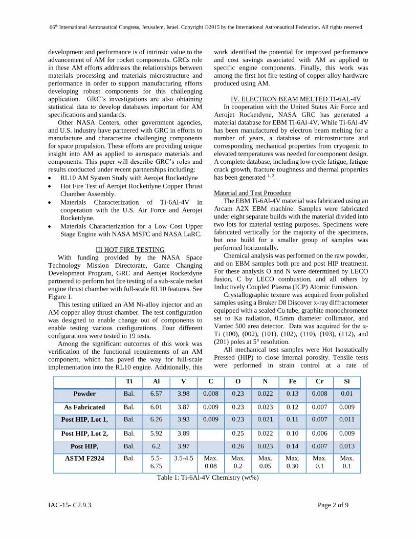
Ti Al V C O N Fe Cr Si
Powder Bal. 6.57 3.98 0.008 0.23 0.022 0.13 0.008 0.01
As Fabricated Bal. 6.01 3.87 0.009 0.23 0.023 0.12 0.007 0.009
Post HIP, Lot 1, Bal. 6.26 3.93 0.009 0.23 0.021 0.11 0.007 0.011
Post HIP, Lot 2, Bal. 5.92 3.89 0.25 0.022 0.10 0.006 0.009
Post HIP, Bal. 6.2 3.97 0.26 0.023 0.14 0.007 0.013
ASTM F2924 Bal. 5.5-
6.75
3.5-4.5 Max.
0.08
Max.
0.2
Max.
0.05
Max.
0.30
Max.
0.1
Max.
0.1
Table 1: Ti-6Al-4V Chemistry (wt%)
66th International Astronautical Congress, Jerusalem, Israel. Copyright ©2015 by the International Astronautical Federation. All rights reserved.
IAC-15- C2.9.3 Page 3 of 9
.0001/sec. High Cycle Fatigue (HCF) tests were
conducted in load control at a frequency of 20-30 Hz.
Tests were performed using a sinusoidal waveform at
three load ratios, Rσ , of -1, 0.1, and 0.5 and test
temperatures of -196, 20, and 149ºC. Ten million cycles
was the runout value for the long-term tests. The crack
origin(s) on every sample was identified using optical
microscopy and Scanning Electron Microscopy (SEM).
Results and Discussion
The chemistry of the starting powder and fabricated
samples was analyzed and is shown in Table I. The same
batch of starting powder was used for all builds.
Compositions were compared to ASTM Standard F2924,
“Standard Specification for Additive Manufacturing
Titanium-6 Aluminum-4 Vanadium with Powder Bed
Fusion.” and results are shown in Table I. The oxygen
content of the starting powder was above the ASTM
standard limit and remained there after fabrication and
HIP. All other elements were within the specification
range.
In the as-fabricated state, the samples contained a
population of porosity that was detected by computed
tomography (CT) and metallography. Pore size was
measured on a metallographic sample and averaged 33 ±
4 μm, with pore size ranging from 7 to 106 μm.
Following HIP, CT and metallography confirmed full
porosity closure.
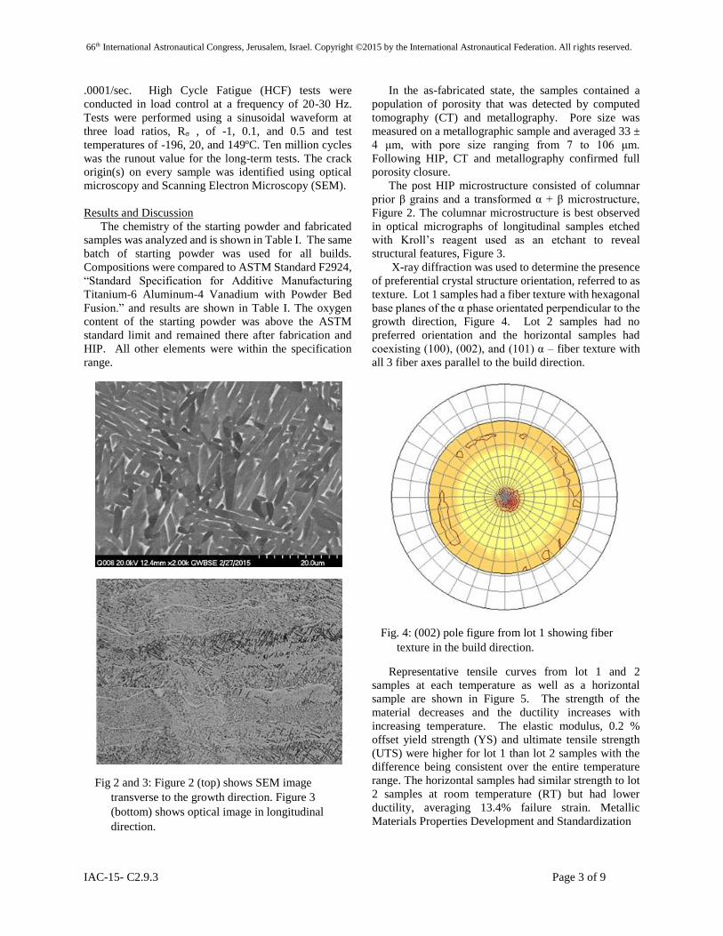
The post HIP microstructure consisted of columnar
prior β grains and a transformed α + β microstructure,
Figure 2. The columnar microstructure is best observed
in optical micrographs of longitudinal samples etched
with Kroll’s reagent used as an etchant to reveal
structural features, Figure 3.
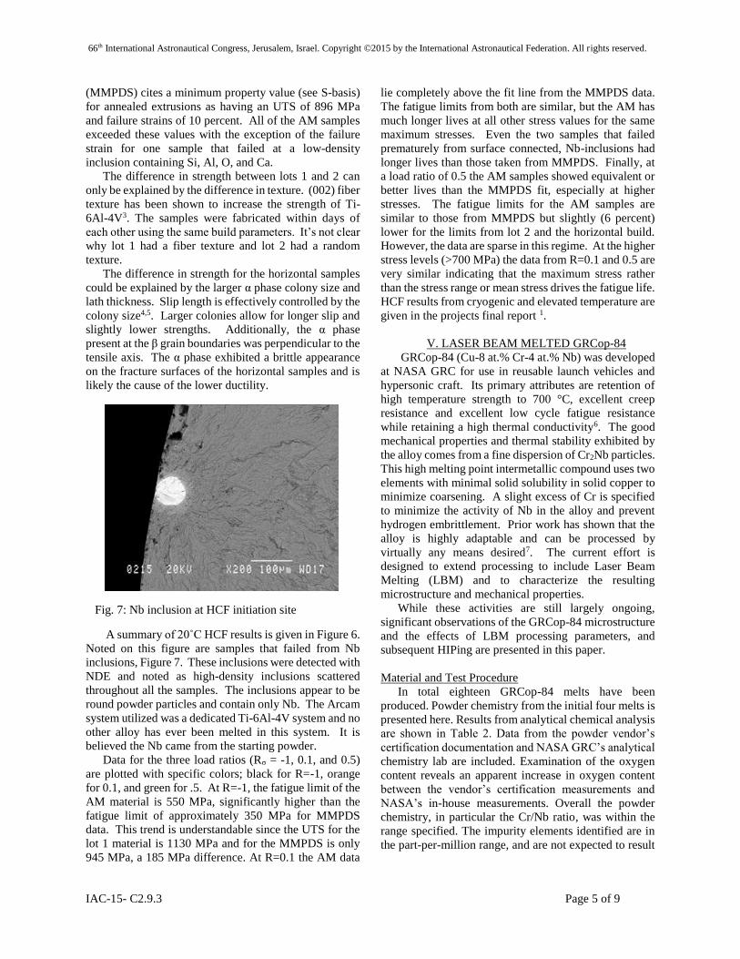
X-ray diffraction was used to determine the presence
of preferential crystal structure orientation, referred to as
texture. Lot 1 samples had a fiber texture with hexagonal
base planes of the α phase orientated perpendicular to the
growth direction, Figure 4. Lot 2 samples had no
preferred orientation and the horizontal samples had
coexisting (100), (002), and (101) α – fiber texture with
all 3 fiber axes parallel to the build direction.
Representative tensile curves from lot 1 and 2
samples at each temperature as well as a horizontal
sample are shown in Figure 5. The strength of the
material decreases and the ductility increases with
increasing temperature. The elastic modulus, 0.2 %
offset yield strength (YS) and ultimate tensile strength
(UTS) were higher for lot 1 than lot 2 samples with the
difference being consistent over the entire temperature
range. The horizontal samples had similar strength to lot
2 samples at room temperature (RT) but had lower
ductility, averaging 13.4% failure strain. Metallic
Materials Properties Development and Standardization
Fig 2 and 3: Figure 2 (top) shows SEM image
transverse to the growth direction. Figure 3
(bottom) shows optical image in longitudinal
direction.
Fig. 4: (002) pole figure from lot 1 showing fiber
texture in the build direction.

66th International Astronautical Congress, Jerusalem, Israel. Copyright ©2015 by the International Astronautical Federation. All rights reserved.
IAC-15- C2.9.3 Page 4 of 9
Fig. 5: Representative tensile curves.
Fig. 6: Room Temperature High Cycle Fatigue Data
66th International Astronautical Congress, Jerusalem, Israel. Copyright ©2015 by the International Astronautical Federation. All rights reserved.
IAC-15- C2.9.3 Page 5 of 9
(MMPDS) cites a minimum property value (see S-basis)
for annealed extrusions as having an UTS of 896 MPa
and failure strains of 10 percent. All of the AM samples
exceeded these values with the exception of the failure
strain for one sample that failed at a low-density
inclusion containing Si, Al, O, and Ca.
The difference in strength between lots 1 and 2 can
only be explained by the difference in texture. (002) fiber
texture has been shown to increase the strength of Ti-
6Al-4V3. The samples were fabricated within days of
each other using the same build parameters. It’s not clear
why lot 1 had a fiber texture and lot 2 had a random
texture.
The difference in strength for the horizontal samples
could be explained by the larger α phase colony size and
lath thickness. Slip length is effectively controlled by the
colony size4,5. Larger colonies allow for longer slip and
slightly lower strengths. Additionally, the α phase
present at the β grain boundaries was perpendicular to the
tensile axis. The α phase exhibited a brittle appearance
on the fracture surfaces of the horizontal samples and is
likely the cause of the lower ductility.
A summary of 20˚C HCF results is given in Figure 6.
Noted on this figure are samples that failed from Nb
inclusions, Figure 7. These inclusions were detected with
NDE and noted as high-density inclusions scattered
throughout all the samples. The inclusions appear to be
round powder particles and contain only Nb. The Arcam
system utilized was a dedicated Ti-6Al-4V system and no
other alloy has ever been melted in this system. It is
believed the Nb came from the starting powder.
Data for the three load ratios (Rσ = -1, 0.1, and 0.5)
are plotted with specific colors; black for R=-1, orange
for 0.1, and green for .5. At R=-1, the fatigue limit of the
AM material is 550 MPa, significantly higher than the
fatigue limit of approximately 350 MPa for MMPDS
data. This trend is understandable since the UTS for the
lot 1 material is 1130 MPa and for the MMPDS is only
945 MPa, a 185 MPa difference. At R=0.1 the AM data
lie completely above the fit line from the MMPDS data.
The fatigue limits from both are similar, but the AM has
much longer lives at all other stress values for the same
maximum stresses. Even the two samples that failed
prematurely from surface connected, Nb-inclusions had
longer lives than those taken from MMPDS. Finally, at
a load ratio of 0.5 the AM samples showed equivalent or
better lives than the MMPDS fit, especially at higher
stresses. The fatigue limits for the AM samples are
similar to those from MMPDS but slightly (6 percent)
lower for the limits from lot 2 and the horizontal build.
However, the data are sparse in this regime. At the higher
stress levels (>700 MPa) the data from R=0.1 and 0.5 are
very similar indicating that the maximum stress rather
than the stress range or mean stress drives the fatigue life.
HCF results from cryogenic and elevated temperature are
given in the projects final report 1.
V. LASER BEAM MELTED GRCop-84
GRCop-84 (Cu-8 at.% Cr-4 at.% Nb) was developed
at NASA GRC for use in reusable launch vehicles and
hypersonic craft. Its primary attributes are retention of
high temperature strength to 700 °C, excellent creep
resistance and excellent low cycle fatigue resistance
while retaining a high thermal conductivity6. The good
mechanical properties and thermal stability exhibited by
the alloy comes from a fine dispersion of Cr2Nb particles.
This high melting point intermetallic compound uses two
elements with minimal solid solubility in solid copper to
minimize coarsening. A slight excess of Cr is specified
to minimize the activity of Nb in the alloy and prevent
hydrogen embrittlement. Prior work has shown that the
alloy is highly adaptable and can be processed by
virtually any means desired7. The current effort is
designed to extend processing to include Laser Beam
Melting (LBM) and to characterize the resulting
microstructure and mechanical properties.
While these activities are still largely ongoing,
significant observations of the GRCop-84 microstructure
and the effects of LBM processing parameters, and
subsequent HIPing are presented in this paper.
Material and Test Procedure
In total eighteen GRCop-84 melts have been
produced. Powder chemistry from the initial four melts is
presented here. Results from analytical chemical analysis
are shown in Table 2. Data from the powder vendor’s
certification documentation and NASA GRC’s analytical
chemistry lab are included. Examination of the oxygen
content reveals an apparent increase in oxygen content
between the vendor’s certification measurements and
NASA’s in-house measurements. Overall the powder
chemistry, in particular the Cr/Nb ratio, was within the
range specified. The impurity elements identified are in
the part-per-million range, and are not expected to result
Fig. 7: Nb inclusion at HCF initiation site

66th International Astronautical Congress, Jerusalem, Israel. Copyright ©2015 by the International Astronautical Federation. All rights reserved.
IAC-15- C2.9.3 Page 6 of 9
in deleterious metallurgical phases or a decrease in
mechanical properties.
Results and Discussion:
Analytical chemistry was performed to examine
changes in oxygen content due to processing. Analysis
was conducted on the starting powder and on LBM
produced samples before and after HIPing. The results
of this analysis are shown in Table 3 and indicate that
there is no significant pickup of oxygen during
processing. The table includes data for the average
powder composition, and for two representative samples
pre and post-HIPing.
To establish build parameters Engineers at the NASA
Marshall Space Flight Center (MSFC) produced several
sets of GRCop-84 specimens for analysis Figure 8. All
specimens were analyzed using optical microscopy and
Computed Tomography (CT) in order to guide MSFC in
the selection of build parameters for the chamber.
Photomicrographs of the extreme processing parameters
are shown in Figures 9 and 10. From these images it can
be seen that build quality, and in particular porosity, are
strongly dependent on processing parameters.
Hot Isostatic Pressing (HIPing) will be performed on
the combustion chamber liner in order to close pores,
anneal the microstructure, and relieve residual stresses
from the build process. To evaluate the results of HIP
processing, samples produced using multiple parameter
sets were HIPed. Optical microscopy of specimens after
HIPing confirmed that very little porosity remained in the
microstructure. Additionally, CT was performed both
pre- and post-HIP. These CT results indicated that very
little, if any, porosity larger than the 6 µm voxel
resolution of the inspection technique remains after the
HIP.
Table 2: GRCop-84 Starting Powder Chemistry (wt%)
From ATI Bottle 1 Bottle 2 Bottle 9 From ATI Bottle 6 Bottle 7 Bottle 10 Bottle 12 From ATI Bottle 3 Bottle 8 Bottle 11 From ATI Bottle 4 Bottle 5
Cu Balance Balance Balance Balance Balance Balance Balance Balance Balance Balance Balance Balance Balance Balance Balance Balance Balance Cu
Cr 6.2-6.8 6.2 6.30 6.30 6.26 6.59 6.59 6.64 6.59 6.66 6.55 6.61 6.58 6.58 6.45 6.63 6.65 Cr
Nb 5.4-6.0 5.72 5.84 5.83 5.83 5.75 5.81 5.85 5.82 5.87 5.64 5.80 5.79 5.79 5.61 5.83 5.84 Nb
Cr/Nb 1.08-1.21 1.08 1.08 1.08 1.07 1.15 1.13 1.14 1.13 1.13 1.16 1.14 1.14 1.14 1.15 1.14 1.14 Cr/Nb
Al <.004 0.006 0.013 0.004 0.006 0.016 0.009 0.007 0.005 <.004 0.011 0.008 0.008 <.004 0.01 0.004 Al
Ca 0.0001 0.0005 0.0045 <.004 0.0027 0.0008 0.0018 0.0024 <.004 0.001 0.001 <.004 Ca
Fe .02 max <.004 0.004 < 0.001 0.003 0.004 0.006 0.004 0.011 0.004 <.004 0.001 0.001 0.001 <.004 0.003 0.002 Fe
Ni <.001 0.016 0.016 0.027 0.016 Ni
Si 0.01 0.005 0.004 0.007 0.003 0.001 0.013 0.002 0.006 0.002 0.002 0.004 0.003 Si
Ti 0.01 0.004 0.005 0.005 0.01 Ti
Y <.005 0.001 <.005 0.002 0.0003 <.005 <.005 0.0001 Y
Zr 0.001 0.001 0.001 <.005 0.002 0.002 0.002 0.002 <.004 0.001 0.001 0.001 <.004 0.003 0.002 Zr
C 0.003 0.005 0.006 0.005 0.002 0.004 0.005 0.005 0.007 0.002 0.003 0.004 0.004 0.002 0.004 0.004 C
N < 0.001 < 0.001 < 0.001 0.002 0.0016 0.0014 0.0015 0.0014 <.001 < 0.001 < 0.001 < 0.001 <.001 0.0013 0.0011 N
O 0.07 max 0.053 0.079 0.070 0.067 0.065 0.066 0.076 0.069 0.085 0.052 0.061 0.066 0.066 0.058 0.091 0.072 O
Melt 522-404 Melt 522-405
SpecElement Element
Melt 522-401 Melt 522-403
Table 3: Analytical chemistry results pre and post HIP (wt%)
Sample TO2-6-
1800
Sample TO2-6-
1800
Sample TO4-
625
Sample TO4-
625
Pre-HIP Post-HIP Pre-HIP Post-HIP
Cu Balance Balance Balance Balance Balance Balance
Cr 6.2-6.8 6.533 6.720 6.800 6.540 6.740
Nb 5.4-6.0 5.825 5.950 6.070 6.100 6.100
CR/Nb 1.08-1.21 1.121 1.129 1.120 1.072 1.105
Al 0.008
Ti 0.007
Y 0.001
Ca 0.002 0.001 0.002 0.001 0.002
Fe .02 max 0.004 0.002 0.003 0.002 0.003
Mg 0.019 0.001 0.001 0.000 0.001
Na 0.004 0.000 0.001 0.000 0.001
Ni 0.007 0.003 0.007 0.003 0.004
Si 0.001 0.006 0.010 0.010 0.012
Zr 0.002 0.002 0.002 0.001 0.001
C 0.005 0.0014, 0.0014 0.0030, 0.0034 0.0015, 0.0019 0.0022, 0.0025
O 0.07 max 0.072 0.060, 0.059 0.066, 0.061 0.066, 0.064 0.066, 0.065
Powder
Specification
Average
Chemisry of
powder
Fig. 8: Example of GRCop-84 samples used for
analysis.
66th International Astronautical Congress, Jerusalem, Israel. Copyright ©2015 by the International Astronautical Federation. All rights reserved.
IAC-15- C2.9.3 Page 7 of 9
Scanning Electron Microscopy (SEM) was
performed on both pre and post-HIP specimens. This
examination revealed the presence of Cr-rich precipitates
that are not present pre-HIP, but are present post-HIP.
Figures 11 and 12 are SEM images with Energy
Dispersive X-ray Spectroscopy (EDS) spectra indicating
chemistry of specific particles and the matrix in the
image.
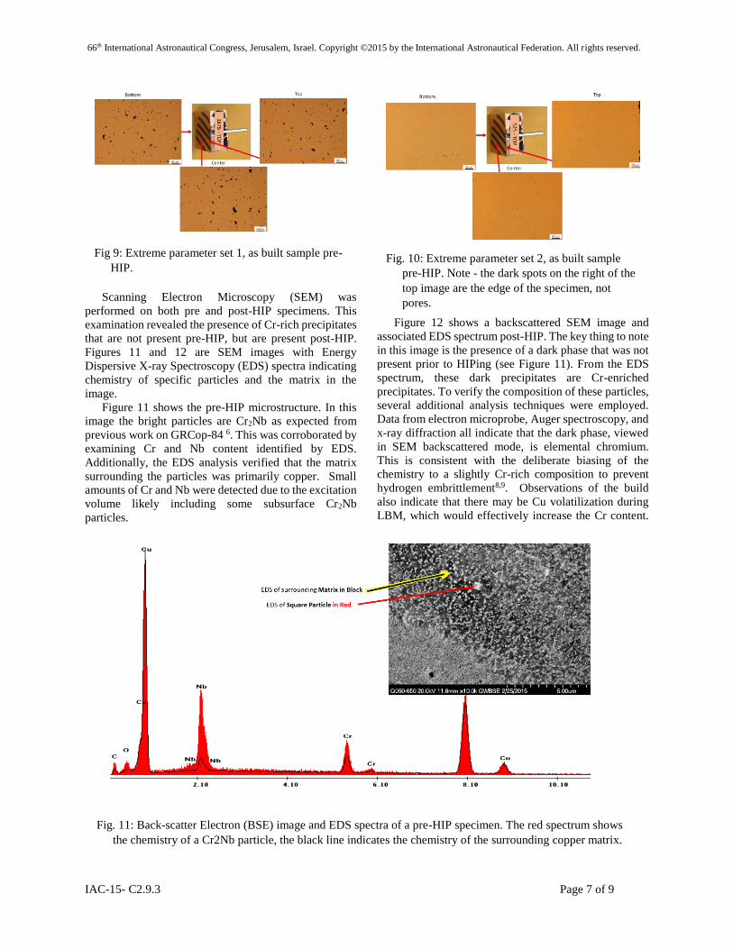
Figure 11 shows the pre-HIP microstructure. In this
image the bright particles are Cr2Nb as expected from
previous work on GRCop-84 6. This was corroborated by
examining Cr and Nb content identified by EDS.
Additionally, the EDS analysis verified that the matrix
surrounding the particles was primarily copper. Small
amounts of Cr and Nb were detected due to the excitation
volume likely including some subsurface Cr2Nb
particles.
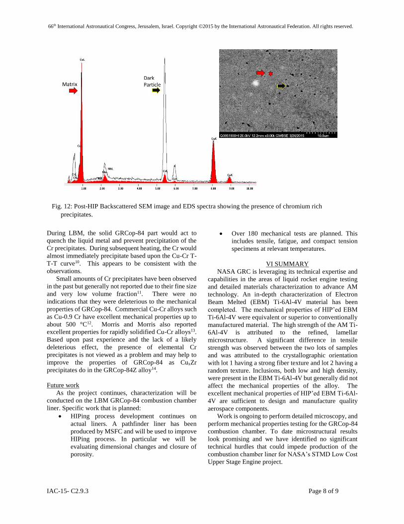
Figure 12 shows a backscattered SEM image and
associated EDS spectrum post-HIP. The key thing to note
in this image is the presence of a dark phase that was not
present prior to HIPing (see Figure 11). From the EDS
spectrum, these dark precipitates are Cr-enriched
precipitates. To verify the composition of these particles,
several additional analysis techniques were employed.
Data from electron microprobe, Auger spectroscopy, and
x-ray diffraction all indicate that the dark phase, viewed
in SEM backscattered mode, is elemental chromium.
This is consistent with the deliberate biasing of the
chemistry to a slightly Cr-rich composition to prevent
hydrogen embrittlement8,9. Observations of the build
also indicate that there may be Cu volatilization during
LBM, which would effectively increase the Cr content.
Fig 9: Extreme parameter set 1, as built sample pre-
HIP.
Fig. 10: Extreme parameter set 2, as built sample
pre-HIP. Note - the dark spots on the right of the
top image are the edge of the specimen, not
pores.
Fig. 11: Back-scatter Electron (BSE) image and EDS spectra of a pre-HIP specimen. The red spectrum shows
the chemistry of a Cr2Nb particle, the black line indicates the chemistry of the surrounding copper matrix.
66th International Astronautical Congress, Jerusalem, Israel. Copyright ©2015 by the International Astronautical Federation. All rights reserved.
IAC-15- C2.9.3 Page 8 of 9
During LBM, the solid GRCop-84 part would act to
quench the liquid metal and prevent precipitation of the
Cr precipitates. During subsequent heating, the Cr would
almost immediately precipitate based upon the Cu-Cr T-
T-T curve10. This appears to be consistent with the
observations.
Small amounts of Cr precipitates have been observed
in the past but generally not reported due to their fine size
and very low volume fraction11. There were no
indications that they were deleterious to the mechanical
properties of GRCop-84. Commercial Cu-Cr alloys such
as Cu-0.9 Cr have excellent mechanical properties up to
about 500 °C12. Morris and Morris also reported
excellent properties for rapidly solidified Cu-Cr alloys13.
Based upon past experience and the lack of a likely
deleterious effect, the presence of elemental Cr
precipitates is not viewed as a problem and may help to
improve the properties of GRCop-84 as CuxZr
precipitates do in the GRCop-84Z alloy14.
Future work
As the project continues, characterization will be
conducted on the LBM GRCop-84 combustion chamber
liner. Specific work that is planned:
HIPing process development continues on
actual liners. A pathfinder liner has been
produced by MSFC and will be used to improve
HIPing process. In particular we will be
evaluating dimensional changes and closure of
porosity.
Over 180 mechanical tests are planned. This
includes tensile, fatigue, and compact tension
specimens at relevant temperatures.
VI SUMMARY
NASA GRC is leveraging its technical expertise and
capabilities in the areas of liquid rocket engine testing
and detailed materials characterization to advance AM
technology. An in-depth characterization of Electron
Beam Melted (EBM) Ti-6Al-4V material has been
completed. The mechanical properties of HIP’ed EBM
Ti-6Al-4V were equivalent or superior to conventionally
manufactured material. The high strength of the AM Ti-
6Al-4V is attributed to the refined, lamellar
microstructure. A significant difference in tensile
strength was observed between the two lots of samples
and was attributed to the crystallographic orientation
with lot 1 having a strong fiber texture and lot 2 having a
random texture. Inclusions, both low and high density,
were present in the EBM Ti-6Al-4V but generally did not
affect the mechanical properties of the alloy. The
excellent mechanical properties of HIP’ed EBM Ti-6Al-
4V are sufficient to design and manufacture quality
aerospace components.
Work is ongoing to perform detailed microscopy, and
perform mechanical properties testing for the GRCop-84
combustion chamber. To date microstructural results
look promising and we have identified no significant
technical hurdles that could impede production of the
combustion chamber liner for NASA’s STMD Low Cost
Upper Stage Engine project.
Fig. 12: Post-HIP Backscattered SEM image and EDS spectra showing the presence of chromium rich
precipitates.
66th International Astronautical Congress, Jerusalem, Israel. Copyright ©2015 by the International Astronautical Federation. All rights reserved.
IAC-15- C2.9.3 Page 9 of 9
In the four powder melts analyzed chemistry was
within the specified range. Additionally, the impurity
elements identified are not expected to result in
deleterious metallurgical phases or a reduction in
mechanical properties. Based upon past experience and
the lack of a likely deleterious effect, the presence of
elemental Cr precipitates in the post HIP microstructure
is not viewed as a problem and may help to improve the
properties of GRCop-84 as CuxZr precipitates do in the
GRCop-84Z alloy.
VII REERENCES
1. Draper, S.L. et al: Proceedings of Ti-2015: The 13th
World Conference on Titanium, TMS, 2015.
2. Draper, S.L. et al: NASA TM to be published in 2015.
3. Semiatin, S.L. and Bieler, T.R.: Metall. and Mat.
Trans. A, 2001, vol. 32A, p.p. 1787-1799, 2001.
4. Nalla, R.K.; Boyce, B.L.; Campbell, J.O.; and
Ritchie, R.O.: Metall. and Mat. Trans. A. 2002, vol.
33A, pp. 899-918.
5. Lutjering, F. and Albrecht, J; Titanium ’95: Science
and Technology Proceedings from the Eighth World
Conference on Titanium, ed. Blenkinsop, P.A. et al,
1995, pp. 1163-1170.
6. D.L. Ellis, “GRCop-84: A High Temperature
Copper-based Alloy for High Heat Flux
Applications,” NASA/TM-2005-213566, E-15011,
Feb. 1, 2005.
7. D. Ellis et al, “A Practical Guide to the Production of
Metal Spun NiCrAlY Coated GRCop-84 Liners,”
NASA TM-2006-214123, April 2006. ITAR
Restricted.
8. D.L. Ellis, A.K. Misra and R.L. Dreshfield, “Effect of
hydrogen exposure on a Cu-8 Cr-4 Nb alloy,” NASA-
TM-106429, E-8271, NAS 1.15:106429, Dec. 1,
1993.
9. D.L. Ellis and K. Hastings, “Effects of Hydrogen on
GRCop-84,” NASA/TM-2006-214269, E-15555,
Apr. 2006.
10. H. Suzuki and M. Kanno, “The T-T-T Curve In Cu-
Cr Alloy”, Nippon Kinzuki Gakkaishi, Vol. 35, No.
5, (1981), pp 434-439. NASA Technical Translation
NASA TT – 20167.
11. K.R. Anderson, J.R. Groza, R.L. Dreshfield, D. Ellis,
“High-Performance dispersion-strengthened Cu-8
Cr-4 Nb alloy”, Met. and Matls. Trans. A, Sept. 1995,
Vol. 26, Iss. 9, pp 2197-2206.
12. H.C. deGroh, D.L. Ellis and W.S. Loewenthal,
“Comparison of GRCop-84 to Other High Thermal
Conductive Cu Alloys,” NASA/TM-2007-214663, E-
15798, Feb 1, 2007.
13. M.A. Morris, D.G. Morris, “Microstructures and
mechanical properties of rapidly solidified Cu-Cr
alloys”, Acta Metallurgica, Volume 35, Issue 10,
October 1987, Pages 2511-2522, ISSN 0001-6160.
14. D.L. Ellis and BA. Lerch, “Improvement of GRCop-
84 through the Addition of Zirconium”, NASA/TM-
2012-216985, E-17626, June 1, 2012.