Embed Size (px)
Citation preview
University of Western Australia
Faculty of Engineering
School of Mechanical Engineering
RoBIOS Library Design for the EyeBot M6
Justin Ward
Supervisor: Thomas Bräunl
ABSTRACT
Embedded robotics are having an ever increasing role in day to day life. As robots have
become more complex they are making their way into our homes to perform simple
chores (iRobot Corporation 2008). The EyeBot M6 is the next in a line of vision robots
that began with the EyeCon – short for EyeBot Controller (Bräunl 2003). This latest
design aims to provide stereo vision, as well as updating the processor, input/output
(I/O) devices (i.e. the inclusion of Bluetooth and USB) and for the first time in the
EyeBot series, uses an FPGA to handle most of the robotic I/O as well as controlling
the cameras.
This hardware platform was initially designed in 2006, with a Gumstix SBC (Single
Board Computer) as the main processor and a Xilinx FPGA operating the cameras
servos, motors, etc. (Blackham 2006). (Hintermann 2007) then went on to implement a
LCD library of functions for the RoBIOS (Robot Basic Input Output System). This paper
presents new functionality to this LCD library, as well as development of Bluetooth for
the RoBIOS and the addition of a GPS to the library. These features will allow the new
EyeBot to enable designs even more sophisticated than the previous version, the EyeBot
M5.
2
1/4 Jupiter Street,
Carlisle,
WA, 6101
3rd November, 2008
The Dean,
Faculty of Engineering, Computing and Mathematics,
The University of Western Australia,
35 Stirling Highway,
Crawley,
WA, 6009
Dear Sir,
I hereby submit to you this dissertation entitled “RoBIOS Library Design for the
EyeBot M6”in partial fulfillment of the requirement of the award of Bachelor of
Engineering.
Yours sincerely,
Justin Ward
3
ACKNOWLEDGMENTS
I would like to take this opportunity to thank those that have made this experience both
possible and enjoyable. Thank you goes first of all to my partner Amy, for putting up
with me over the last year (and especially over the last few months). I would also like to
thank my friends and family for all their support and encouragement. Thanks must also
go to Rachel, for keeping me supplied with coffee as required.
Within the EyeBot team I owe a debt of gratitude to Azman Yusof for all his help, and
to all the previous students who have worked on this project. Finally, but not least,
thank you to Thomas Bräunl and Ivan Neubronner. Thomas for his guidance and
support and Ivan for his expertise and dedication to this project.
4
TABLE OF CONTENTS
ABSTRACT................................................................................................................................................ 2 ACKNOWLEDGMENTS ......................................................................................................................... 4 TABLE OF CONTENTS........................................................................................................................... 5 TABLE OF FIGURES............................................................................................................................... 6 NOMENCLATURE................................................................................................................................... 7 CHAPTER 1: INTRODUCTION ............................................................................................................ 8
1.1 DEVELOPMENT OF EMBEDDED SYSTEMS.................................................................................. 8 1.2 STRUCTURE ............................................................................................................................. 8
CHAPTER 2: LITERATURE SURVEY ................................................................................................ 9 2.1 A STUDY OF MOBILE ROBOTS................................................................................................... 9
2.1.1 THE XBC CONTROLLER ........................................................................................................ 10 2.1.2 ORTHOGONAL-SLAM ........................................................................................................... 11
2.2 DESIGN OF THE M6................................................................................................................ 12 CHAPTER 3: THEORY......................................................................................................................... 15
3.1 DESIGN OF EMBEDDED SOFTWARE........................................................................................ 15 3.2 DESIGN OF THE EYEBOT M6 ................................................................................................. 16 3.3 WORKING WITH LINUX.......................................................................................................... 17
3.3.1 BLUETOOTH AND THE BLUEZ INTERFACE.............................................................................. 18 3.3.2 UDEV CONFIGURATION ......................................................................................................... 18
CHAPTER 4: IMPLEMENTATION OF LIBRARY FUNCTIONS.................................................. 20 4.1 DESIGNING LIBM6GPS ........................................................................................................... 20 4.2 MODIFICATION OF LIBM6LCD ............................................................................................... 21 4.3 WRITING LIBM6BLUE............................................................................................................ 23 4.4 USING UDEV TO MAP DEVICES TO FIXED LOCATIONS ............................................................. 23
CHAPTER 5: DISCUSSION OF RESULTS........................................................................................ 25 5.1 OPERATION OF LIBM6GPS ..................................................................................................... 25 5.2 OPERATION OF LIBM6LCD..................................................................................................... 27 5.3 OPERATION OF LIBM6BLUE ................................................................................................... 29 5.4 USING UDEV TO MAP DEVICES TO FIXED LOCATIONS ............................................................. 31 5.5 OBTAINING ACCESS TO CODE DEVELOPED ............................................................................. 31 5.6 DIFFICULTIES ENCOUNTERED DURING THE PROJECT .............................................................. 32
CHAPTER 6: CONCLUSIONS AND RECOMMENDATIONS........................................................ 33 6.1 CURRENT STATE OF THE ART ................................................................................................. 33 6.2 THE EYEBOT M6................................................................................................................... 34 6.3 FUTURE WORK....................................................................................................................... 34
REFERENCES......................................................................................................................................... 35 APPENDIX 1 ............................................................................................................................................ 37
5
TABLE OF FIGURES
FIGURE 1 - THE XBC CONTROLLER (LEGRAND ET AL. 2005) ....................................................................... 9
FIGURE 2 - TOP SIDE OF EYEBOT M6 ILLUSTRATING HARDWARE ............................................................... 12
FIGURE 3 - THE BOTTOM OF THE EYEBOT M6 ILLUSTRATING THE I/O CONNECTORS ................................. 13
FIGURE 4 - THE SIDE OF THE EYEBOT M6 ILLUSTRATING POWER PORTS AND MODERN CONNECTIVITY
DEVICES .................................................................................................................................... 14
FIGURE 5 - THE GUMSTIX CONNEX USED IN THE EYEBOT M6 (GUMSTIX CONNEX 400XM-BT 2008) .......... 16
FIGURE 6 - THE EYEBOT M6 CONTROLLER LAYOUT (BLACKHAM 2006) ................................................... 17
FIGURE 7 - ONE READING OF THE GETGPSDATA TEST-DEMO PROGRAM ..................................................... 26
FIGURE 8 - VIEW OF GPSMAPUNI IN OPPERATION, NOTE THE YELLOW SQUARE INDICATING USERS POSITION
IS AN EXTREME EXAGERATION. THE STANDARD SIZE IS 3X3 PIXELS.......................................... 27
FIGURE 9 - THE CLASH BETWEEN LARGE AND SMALL TEXT ON SCREEN IS VISIBLE. THE SAME MESSAGE WAS
PRINTED TO SCEEN FOR BOTH TEXT SIZES BOTH CURSOR POSITIONS STARTED AT (0,0) ............. 28
FIGURE 10 - A SCREEN SHOT OF PART OF THE TEST-LIBM6LCD PROGRAM, BOTH FONT SIZES ARE DISPLAYED
SIMULTANEOUSLY..................................................................................................................... 29
FIGURE 11 - THIS SHOWS THE SCREEN OUTPUT OF THE CHOOSEPATNER() FUNCTION IN LIBM6BLUE........... 30
6
NOMENCLATURE
ARM Acorn RISC Machine
ASCII American Standard Code for Information Interchange
CIIPS Centre for Intelligent Information Processing Systems
CPU Central Processing Unit
DIO Digital Input Output
FPGA Field Programmable Gate Array
GBA Game Boy Advance
GPS Global Positioning System
HID Human Interface Device
LCD Liquid Crystal Display
OBEX Object Exchange
RISC Reduced Instruction Set Computing
RoBIOS Robot Basic Input Output System
7
CHAPTER 1: INTRODUCTION 1.1 DEVELOPMENT OF EMBEDDED SYSTEMS
Mobile robotics continues to be an exciting area of development. We have now seen
several generations of the Honda robot Asimo (Honda Motor Co. 2008), each more able
to integrate into the human world than the last. As well as this, NASA and other
organisations are probing the depths of space with autonomous satellites, as well as
other planets with Martian rovers. In our homes there is a gradually increasing
acceptance of robotic devices, such as the Roomba robotic vacuum cleaner (iRobot
Corporation 2008).
1.2 STRUCTURE
This paper is focused on developing hardware interfacing as part of a new RoBIOS
(Robot Basic Input Output System) library for the production of a new robotic
controller, the EyeBot M6, which will allow far more sophisticated designs than were
possible with the EyeBot M5. Functionality for reading GPS information from a USB to
Serial GPS device is written into the RoBIOS, as well as an extension of the LCD
library and development of a Bluetooth interface for the library.
Chapter 2 looks at progress made to date with design work in the area of mobile
robotics and the tasks associated with this type of robot. Specific examples are given
and the effectiveness of each is discussed. Also discussed in this chapter is work that
has already been completed on the project before the writers work began. Chapter 3
looks at the theory and prior knowledge necessary for the writer to complete the
intended goals of this project, while Chapter 4 details the methods used to achieve the
goals. Chapter 5 discusses the results of the project and analyses the benefits. Finally,
Chapter 6 contains recommendations for future work and draws to a conclusion this
body of work.
8
CHAPTER 2: LITERATURE SURVEY 2.1 A STUDY OF MOBILE ROBOTS
One of the first mobile robots created was the Machina speculartrix, produced by (Grey
1951). This was a set of 2 robots, Elsie and Elmer, which operated on the principle of
exploring their environment and seeking out light sources while avoiding obstacles.
When the battery of the robot began to fail, it would seek out its home (a battery
recharging station). This robot was based on analogue circuits with its “brain”
consisting of 2 vacuum tubes connected in several different ways – similar to a human
brain – that controlled the motors for the wheels. While this may have been
revolutionary for the time, it did not pose any useful purpose.
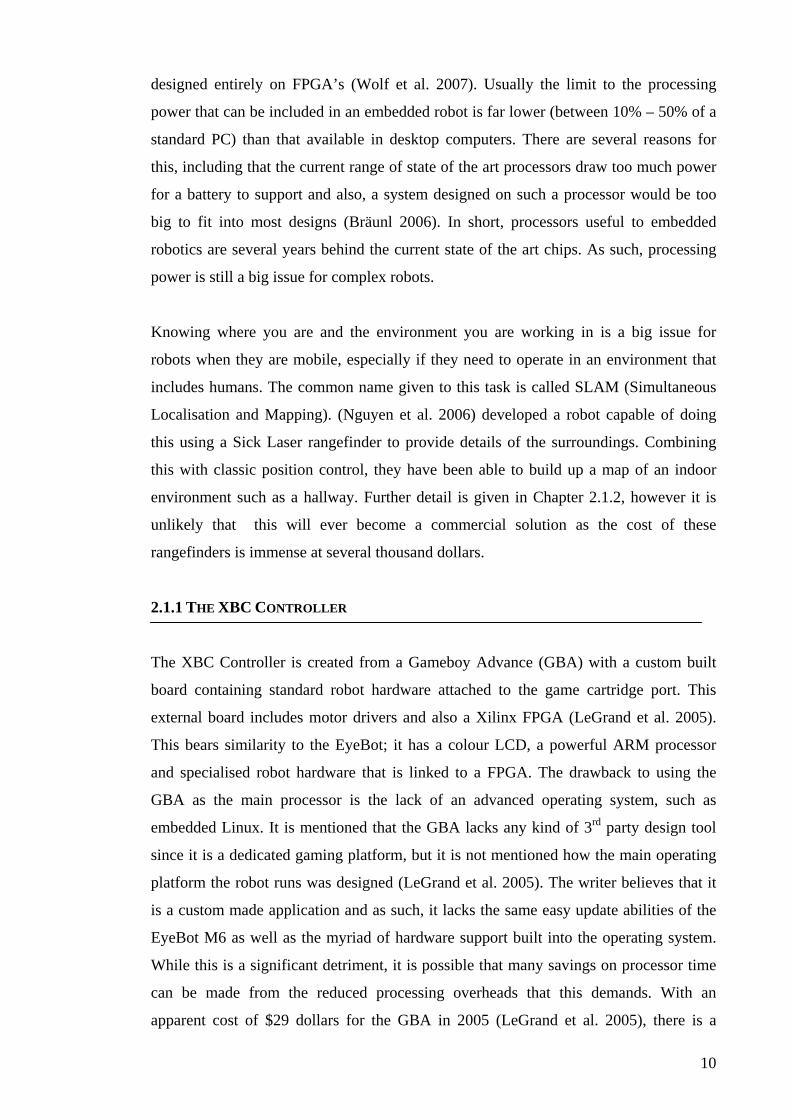
Figure 1 - The XBC Controller (LeGrand et al. 2005)
The continued development of robotic hardware and the development of the
microprocessor lead to a much greater focus on digital system designs for robotics.
These circuits have the advantage of providing reliable repeatable results. However,
there is still a huge range of different designs in the architecture of the control systems
for these robots. The XBC (LeGrand et al. 2005) pictured in Figure 1 runs on an ARM
processor which has been hijacked from a Gameboy Advance, while others have been
9
designed entirely on FPGA’s (Wolf et al. 2007). Usually the limit to the processing
power that can be included in an embedded robot is far lower (between 10% – 50% of a
standard PC) than that available in desktop computers. There are several reasons for
this, including that the current range of state of the art processors draw too much power
for a battery to support and also, a system designed on such a processor would be too
big to fit into most designs (Bräunl 2006). In short, processors useful to embedded
robotics are several years behind the current state of the art chips. As such, processing
power is still a big issue for complex robots.
Knowing where you are and the environment you are working in is a big issue for
robots when they are mobile, especially if they need to operate in an environment that
includes humans. The common name given to this task is called SLAM (Simultaneous
Localisation and Mapping). (Nguyen et al. 2006) developed a robot capable of doing
this using a Sick Laser rangefinder to provide details of the surroundings. Combining
this with classic position control, they have been able to build up a map of an indoor
environment such as a hallway. Further detail is given in Chapter 2.1.2, however it is
unlikely that this will ever become a commercial solution as the cost of these
rangefinders is immense at several thousand dollars.
2.1.1 THE XBC CONTROLLER
The XBC Controller is created from a Gameboy Advance (GBA) with a custom built
board containing standard robot hardware attached to the game cartridge port. This
external board includes motor drivers and also a Xilinx FPGA (LeGrand et al. 2005).
This bears similarity to the EyeBot; it has a colour LCD, a powerful ARM processor
and specialised robot hardware that is linked to a FPGA. The drawback to using the
GBA as the main processor is the lack of an advanced operating system, such as
embedded Linux. It is mentioned that the GBA lacks any kind of 3rd party design tool
since it is a dedicated gaming platform, but it is not mentioned how the main operating
platform the robot runs was designed (LeGrand et al. 2005). The writer believes that it
is a custom made application and as such, it lacks the same easy update abilities of the
EyeBot M6 as well as the myriad of hardware support built into the operating system.
While this is a significant detriment, it is possible that many savings on processor time
can be made from the reduced processing overheads that this demands. With an
apparent cost of $29 dollars for the GBA in 2005 (LeGrand et al. 2005), there is a
10
significant price difference between it and the Gumstix platform as the core of the
EyeBot controller at $169 each (Gumstix 2008). However, since the release of the
Nintendo DS replacing the GBA at a much higher price, the writer suspects that a
design such as this one would now be much more expensive. However, at the time that
it was produced the writer believes that it offered a substantial benefit over hardware
available (especially at the price). Ultimately the XBC and EyeBot have a slightly
different goal, with the XBC being targeted at giving new users of robotics a soft entry
into the field, while the EyeBot is aimed as a powerful sophisticated controller,
justifying the higher price for components.
2.1.2 ORTHOGONAL-SLAM
Orthogonal SLAM is a method of SLAM which only looks at series of pependicular
lines. The justification for only looking at perpendicular lines is that these are the main
features in most indoor environments (windows, walls and floors all meet at
perpendicular lines). The results produced from the paper by (Nguyen et al. 2006) are
given as validation for this approach. However, there is no discussion in this paper as to
the effects of say a room cluttered with random objects or a situation in the middle of a
room with chairs where walls would be obscured and the chairs may present non-
perpendicular lines. Further, (Nguyen et al. 2006) presents this paper as a lightweight
algorithm for a mobile robot to keep computation low, however the test bench was a
laptop running the program ontop of a robot already with its own controller. In a mobile
robot, where power draw is an issue, this would not be practical. Also the sensors used
were SICK laser range finders, which at several thousand dollars are unlikely to be used
on a large scale due to their cost. The writer believes that devices using such high cost
sensors would not be able to be made proffitably in domestic applications with such a
high price tag, especially when the competition is so much cheaper at appoximately
$200 (iRobot Corporation 2008). For such a task, the writer believes that the solution
lies in cheaper hardware i.e. CCD cameras coupled with more efficient algorithms for
processing i.e. FPGA implementation for algorithms.
11
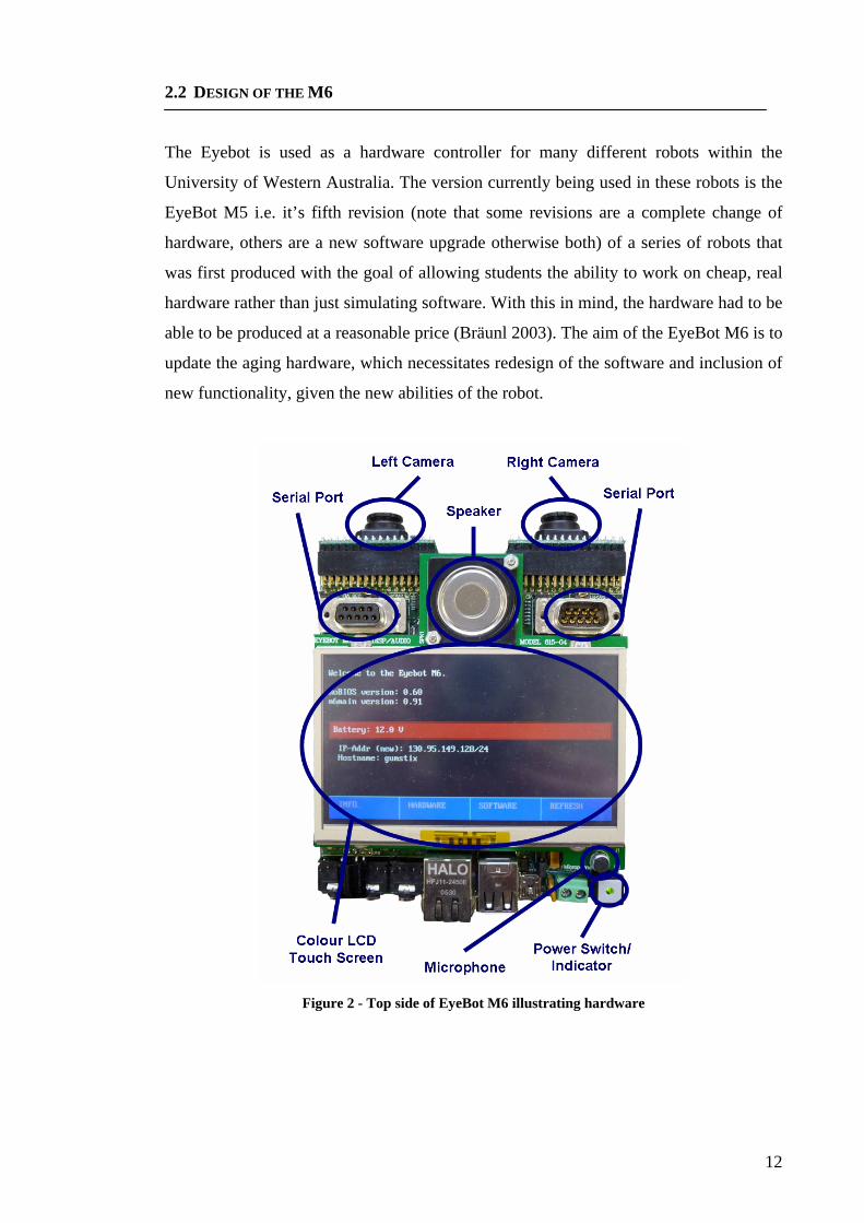
2.2 DESIGN OF THE M6
The Eyebot is used as a hardware controller for many different robots within the
University of Western Australia. The version currently being used in these robots is the
EyeBot M5 i.e. it’s fifth revision (note that some revisions are a complete change of
hardware, others are a new software upgrade otherwise both) of a series of robots that
was first produced with the goal of allowing students the ability to work on cheap, real
hardware rather than just simulating software. With this in mind, the hardware had to be
able to be produced at a reasonable price (Bräunl 2003). The aim of the EyeBot M6 is to
update the aging hardware, which necessitates redesign of the software and inclusion of
new functionality, given the new abilities of the robot.
Figure 2 - Top side of EyeBot M6 illustrating hardware
12
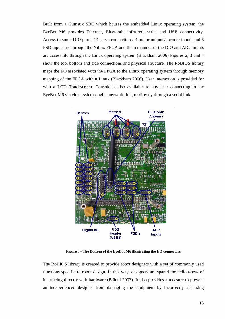
Built from a Gumstix SBC which houses the embedded Linux operating system, the
EyeBot M6 provides Ethernet, Bluetooth, infra-red, serial and USB connectivity.
Access to some DIO ports, 14 servo connections, 4 motor outputs/encoder inputs and 6
PSD inputs are through the Xilinx FPGA and the remainder of the DIO and ADC inputs
are accessible through the Linux operating system (Blackham 2006) Figures 2, 3 and 4
show the top, bottom and side connections and physical structure. The RoBIOS library
maps the I/O associated with the FPGA to the Linux operating system through memory
mapping of the FPGA within Linux (Blackham 2006). User interaction is provided for
with a LCD Touchscreen. Console is also available to any user connecting to the
EyeBot M6 via either ssh through a network link, or directly through a serial link.
Figure 3 - The Bottom of the EyeBot M6 illustrating the I/O connectors
The RoBIOS library is created to provide robot designers with a set of commonly used
functions specific to robot design. In this way, designers are spared the tediousness of
interfacing directly with hardware (Bräunl 2003). It also provides a measure to prevent
an inexperienced designer from damaging the equipment by incorrectly accessing
13
hardware devices. Using the operating system from Gumstix has its advantages in that it
is specifically designed for the target system, it is maintained up to date and it is freely
accessible. However, it also has its disadvantages. Unfortunately, this is not a real time
Linux distribution and any process which has timing constraints cannot be guaranteed
that these will be met. This can cause problems with any robotic system which relies on
high speed continuous results being available.
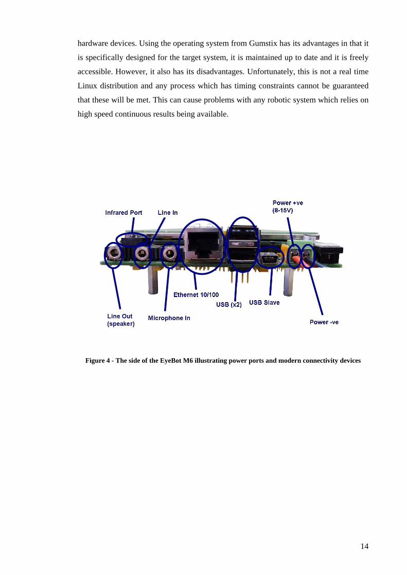
Figure 4 - The side of the EyeBot M6 illustrating power ports and modern connectivity devices
14
CHAPTER 3: THEORY 3.1 DESIGN OF EMBEDDED SOFTWARE
Generally speaking, and certainly in the case of the EyeBot M6 and its predecessors,
there isn’t room on the controller (target) itself for the software components necessary
for the design and compilation of programs. Instead design, compilation and as much
testing as possible is conducted on another computer (the host) and is then transferred to
the controller. To do this, a cross-compiler is needed on the host computer that can
translate the source code into machine code that can then be read by the controller. The
manufacturer of the Gumstix provides this in the form of buildroot. This is a series of
makefiles which creates the entire tool chain needed for development of software for the
system (Blackham 2006).
Buildroot is makefile based and will only work on a Linux operating system natively,
however a Windows cross compiler has been created for the EyeBot M6 (Hintermann
2007). This allows programmers to develop in the system of their preference, which is
of great benefit to designers of user programs. However, in the design and development
of software dealing directly with hardware, much of the benefit of developing on
Windows is lost, as the designer needs intimate knowledge of the operating system to
correctly interface with hardware. For this reason the writer has chosen to develop on a
Linux platform. In this way access to a plethora of functions using the Shell are
available and commands are interchangeable between host and target.
Developing code in Linux also has the benefit that with no modification, code for the
EyeBot can first be tested on the host PC, with the exception of hardware specific
functions (such as LCD library functions). In this way, testing for the GPS and
Bluetooth can be performed even when access to the EyeBot is not available.
15
3.2 DESIGN OF THE EYEBOT M6
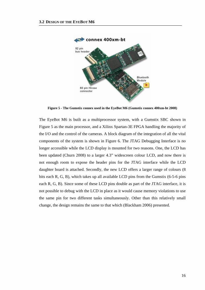
Figure 5 - The Gumstix connex used in the EyeBot M6 (Gumstix connex 400xm-bt 2008)
The EyeBot M6 is built as a multiprocessor system, with a Gumstix SBC shown in
Figure 5 as the main processor, and a Xilinx Spartan-3E FPGA handling the majority of
the I/O and the control of the cameras. A block diagram of the integration of all the vital
components of the system is shown in Figure 6. The JTAG Debugging Interface is no
longer accessible while the LCD display is mounted for two reasons. One, the LCD has
been updated (Churn 2008) to a larger 4.3” widescreen colour LCD, and now there is
not enough room to expose the header pins for the JTAG interface while the LCD
daughter board is attached. Secondly, the new LCD offers a larger range of colours (8
bits each R, G, B), which takes up all available LCD pins from the Gumstix (6-5-6 pins
each R, G, B). Since some of these LCD pins double as part of the JTAG interface, it is
not possible to debug with the LCD in place as it would cause memory violations to use
the same pin for two different tasks simultaneously. Other than this relatively small
change, the design remains the same to that which (Blackham 2006) presented.
16
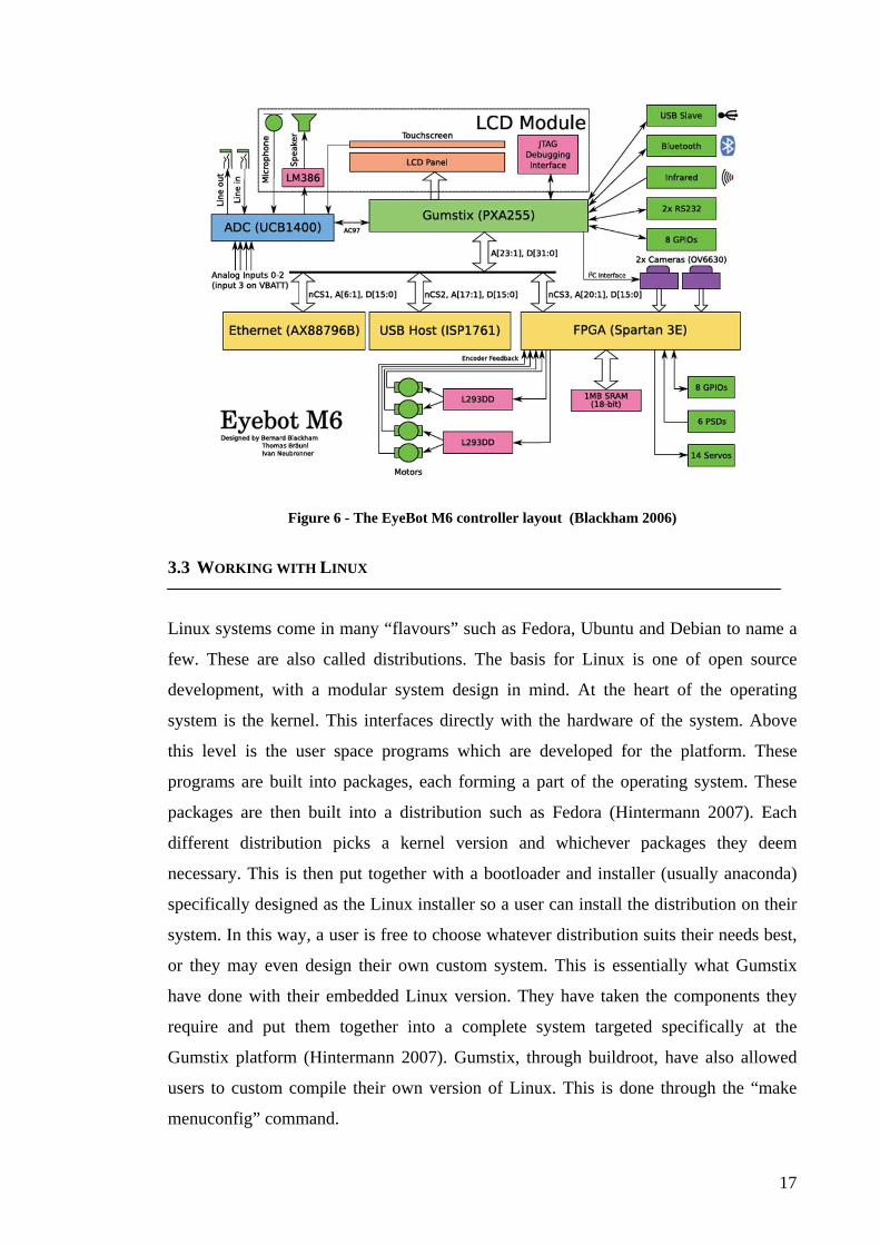
Figure 6 - The EyeBot M6 controller layout (Blackham 2006)
3.3 WORKING WITH LINUX
Linux systems come in many “flavours” such as Fedora, Ubuntu and Debian to name a
few. These are also called distributions. The basis for Linux is one of open source
development, with a modular system design in mind. At the heart of the operating
system is the kernel. This interfaces directly with the hardware of the system. Above
this level is the user space programs which are developed for the platform. These
programs are built into packages, each forming a part of the operating system. These
packages are then built into a distribution such as Fedora (Hintermann 2007). Each
different distribution picks a kernel version and whichever packages they deem
necessary. This is then put together with a bootloader and installer (usually anaconda)
specifically designed as the Linux installer so a user can install the distribution on their
system. In this way, a user is free to choose whatever distribution suits their needs best,
or they may even design their own custom system. This is essentially what Gumstix
have done with their embedded Linux version. They have taken the components they
require and put them together into a complete system targeted specifically at the
Gumstix platform (Hintermann 2007). Gumstix, through buildroot, have also allowed
users to custom compile their own version of Linux. This is done through the “make
menuconfig” command.
17
3.3.1 BLUETOOTH AND THE BLUEZ INTERFACE
Bluetooth is a wireless data transfer standard, designed as a very low power, short range
transfer protocol. This Bluetooth special interest group (SIG) was first formed in 1998
(Bluetooth SIG 2008). The standard is currently at version 2.1 however devices
currently in use and on the marked are also using the version 1.2 standard. The standard
now encompasses many different transfer protocols, i.e. voice profile, fax profile and
general object exchange (OBEX).
The BlueZ stack is a set of binaries and development libraries describing Bluetooth
protocols and device drivers to allow integration of Bluetooth devices into Linux. It
contains a set of library headers for the development of Bluetooth programs and applets
in the C programming language. There are two main separate design protocols for
setting up a connection in Bluetooth and transferring data – the rfcomm layer and the
l2cap layer. The rfcomm layer is designed around connection integrity and is similar to
TCP/IP transfer protocols in nature (Huang 2005). The rfcomm layer is best for long
term connections while the l2cap layer on the other hand is better for short term
communication, i.e. single file transfer (Huang 2005).
Gumstix provides, as part of the buildroot tool chain, development libraries in the form
of the BlueZ stack and the BlueZ library of development files. Common tools used for
configuring and manipulating Bluetooth devices, as well as creating connections from
the console prompt, are the commands hcitool, hciconfig and rfcomm. Typing man
[command], i.e. man hcitool, into any Linux console will provide semantics and options
for the function. However, this will not work on the EyeBot itself (manuals are not
installed to conserve space in memory).
3.3.2 UDEV CONFIGURATION
Udev performs device naming for userspace. Its purpose is to create a dynamic /dev
(/dev is the space in memory where all physical memory is mapped) i.e. to dynamically
create a position in /dev for each hard drive, thumb drive, printer, serial device etc. that
is connected to the computer. It is built to provide consistent device naming if the user
desires. The program udev does this by creating symlinks between a devices /dev
address, and the chosen location in memory for the symlink. So if a user desires that
18
their portable hard drive is always mounted to the location /media/portable_drive, they
can add a new rules file to the /etc/udev/rules.d folder specifying this requirement
(Kroah-Hartman 2003).
Note that the device addresses in /dev are dynamically assigned (Kroah-Hartman 2003),
that is, if 3 external memory devices are plugged in drive1, drive2 and drive3 the
address they are given in /dev will depend upon the order that they are plugged in each
time. If on the first connection the user were to plug in these drives in numerical order,
1, 2 then 3, the locations in /dev would be as follows drive1 mapped to /dev/sda1, drive
2 to /dev/sdb1 and drive3 /dev/sdc1. However, if the user was then to remove them and
reconnect them in the order 3, 1, 2, their mappings in /dev will change to drive3 mapped
to /dev/sda1. It should also be noted that multiple symlinks can be created for the one
/dev device.
Udev has two ways of binding locations in /dev to another memory location. The first is
to map a device based on the /dev address, so if the user knew their external hard drive
was always located at /dev/sda1 then their symlink rule can be based on this. However,
if the location is not always /dev/sda1, because the order in which the users hard drives
are connected is not fixed, the user can use information they know about the drive (such
as manufacturer, model, serial number etc.) to create the rule (Drake 2006).
19
CHAPTER 4: Implementation of library functions As described in the theory and literary review sections of this thesis, the RoBIOS library
is already partially completed, but is still lacking some requisite functionality. The
addition of these components is discussed below.
In designing this RoBIOS library for the EyeBot M6, it is important to note the
differences between the M5 and the M6. In many instances code from the old system
has had to be significantly modified or rewritten altogether. Where new technology has
been added to the RoBIOS library, these functions must be designed and added.
4.1 DESIGNING LIBM6GPS
In line with the requirements of the RoBIOS library functionality, there should be
functions written in the RoBIOS library to allow access of all installed hardware
devices. The writer took on the challenge of writing such a library for a GPS device.
The hardware chosen as a standard GPS device is a BU-353, chosen for its small and
compact size, lightweight manufacture and its price and availability within the CIIPS
department. The interface of this device is a USB connection with a USB to serial
interface driver. This is perfect for the EyeBot M6 which has 2 USB connections as
well as header pins for a third. The nature of USB also allows for expansion of each
port with further expansion hubs, allowing for many USB devices on the one system.
While (Blackham 2006) successfully wrote a host driver for the USB host controller
installed on the EyeBot, the modules for USB devices installed on the current hardware
did not include some of those required when the writer began work. The build root
system that is provided with the Gumstix board provides a make file configuration for
designing the target system (the EyeBot), including drivers. However, since this system
isn’t shipped with a USB Host as standard, these modules aren’t compiled in a standard
build of the operating system, nor are they included in the flash image that is
subsequently installed on the Gumstix. Perhaps their lack of inclusion was intentional
on the part of (Blackham 2006), given no knowledge of USB devices to be used and
wanting to save space as a priority. So, to use the GPS device, first the necessary system
modules had to be compiled and installed on the EyeBot.
20
Since such modules form an integral part of the operating system and depend highly on
the construction, these are usually only built as part of an entire system. However, it
was desired to only update the required USB modules, not the whole system if possible.
To do this successfully, a new build of the system with the same options (with the
exception of building the new modules) is required. Since (Blackham 2006) made some
modifications of his own to the standard build, and the writer did not have access to his
buildroot environment, parameters that he had changed (such as the Linux version
name, changed from linux-2.6.17gum, to linux-2.6.17eye) had to be changed in the
writers version to allow successful use of the compiled modules on the operating system
already installed.
Most commercial GPS devices output ASCII text as a series of strings starting with an
identifier such as $GPRMC, $GPGGA etc. and containing comma separated fields as
defined by the NMEA-0183 standard (Adamchuk 2001). For the RoBIOS library an
easy to use function is required to give the user access to this data. The constraints are a
low processing overhead and the ability to return readings quickly to the user. To keep
the required processing power to a minimum, only one string is processed, the
$GPRMC (Recommended Minimum Specific GPS Data) string. This one string
provides access to latitude, longitude, UTC time, speed in knots, heading, date,
magnetic variation from due North and a checksum to validate the information.
(Adamchuk 2001)
4.2 MODIFICATION OF LIBM6LCD
The LCD library written by (Hintermann 2007) provides a wide range of useful
functions to allow easy use of the LCD without resorting to interfacing directly with the
Linux frame buffer device (fb). This library has been updated in parts by Azman Yusof.
What the library lacks is the ability to print a larger text size, so that when the robot is
moving text is easily readable. Also, since the EyeBot is being used in cars as part of the
REV project (Mathew 2008), a large text display is needed so that drivers can see
information on the screen while driving without being distracted. It is not appropriate to
increase the default size of the text on the screen as the size was chosen on purpose so
that a large volume of information can be displayed and this need remains. What is
needed is a second font size, twice the size of the original, which will allow for easier
21
reading. The difficulty in producing such a font is the method in which the library is
written. Writing to the LCD screen, as well as setting refresh rates and timings, is all
handled by the Linux (fb). This is a primitive way of controlling a screen when a full X
Window system is not wanted or needed. As such, it lacks many of the features of a full
system, including control over font types and sizes. The current text buffer would be
difficult to modify for two reasons. One it is very primitive and would greatly increase
complexity (and hence processing time) to add support for changing font size and two,
the key library which monitors active regions of the screen relies on the font size for
working out active regions. Thus if the text size were changed in the text buffer during
runtimes, it would cause unpredictable effects and most probably run time errors in the
key library.
The alternative is to create a second graphics buffer for implementing a graphics font
and merge this graphics buffer with the standard graphics buffer (for drawing pictures
etc.) before mapping them in memory to the fb device. This way, two font sizes can be
displayed simultaneously while keeping the complexity, and thus processor
requirements of the LCD library small. The disadvantages of using a graphics based
implementation are first the storage needed to hold the image library size and secondly
the notorious nature of bitmap fonts to be unrecognisable if scaled. Fortunately, since
the font size is known at the time of creation and will not be changed, this is not a
problem.
To create the new font library an easy method of automatic generation is desired. This
makes it easier to test out different fonts and point sizes during testing, as well as
allowing for easy modification of font type or size in the future. For this reason the
convert() command line function was chosen for its ability to accept a canvas size, point
size, foreground and background colour with one or more characters and convert this to
a .ppm picture file with the aforementioned properties. This is then converted to the
same format as frame buffer data to allow fast runtime operation within the one C
program that allows fast automatic generation of all written characters in ASCII into the
required text file or .c file. This file is easily modified to allow a change in font type or
size.
During development of the RoBIOS library, it is beneficial that all programs be
compiled to run without the custom built EyeBot library. This makes it easy to test
22
programs without worrying that there may be an old library on the target system that is
corrupting the program. However, once the library is finished this will change and an
EyeBot.a file will be included on each controller to allow easy access of RoBIOS
functions. To suit both of these situations, two implementations have been developed
for the new libM6lcd library. The first includes the new graphics library as a text file to
be read in by the program during runtime to keep user programs small. A second which
contains the new font in a .c file large_text_font.c, to keep operating speed high during
run time and maximize the benefit of having an EyeBot library on the EyeBot M6 once
operating fully.
4.3 WRITING LIBM6BLUE
There are so many different implementations of Bluetooth protocols, and many different
layers of the Bluetooth protocol, it can be very difficult for a designer to know where to
begin. This is made worse when the designer is not focused on hardware, but on
implementing a robotic design at a higher functional level. To remove the need for a
user software designer to deal with the hardware level, the writer presents a library
which allows a designer to deal with Bluetooth in much the same way as they would
without having to understand fully the complexity of the hardware.
In the previous EyeBot, the M5, a library, libM6radio, was written to allow the EyeBot
to use a wireless radio module connected to a serial port to communicate with other
EyeBots in the region (Wilke & Bräunl 2001). It makes sense to use the inbuilt
Bluetooth to recreate the libM6radio library, however, due to the complexity of
Bluetooth, first a protocol for sending and receiving data with the Bluetooth module
needs to be created. This acts as a library in itself to allow modification of libM6radio,
and as a general purpose wireless data transfer protocol for users wanting to transfer
data between Bluetooth devices without delving too deeply into the hardware.
4.4 USING UDEV TO MAP DEVICES TO FIXED LOCATIONS
It is desirable to allow users of the EyeBot to log data to an external device
automatically (that is without the user needing to perform a manual copy). Also it is
foreseeable that a user will need to record a large amount of data, for example if a user
needs to store lots of frames from the cameras. To enable EyeBot users access to this
23
extra memory space in the form of an external drive (i.e. portable hard drive or USB
thumb drive), a fixed position in memory is required, allowing simple access to the user.
The solution is to use /dev to mount an external drive connected via USB to the location
/dev/usbdrive. It is impossible to determine the manufacturer or model of a memory
device that a user may connect to the EyeBot for automatic data storage. So it is also
impossible to use a symlink rule based on a device property to map a /dev address to
/mnt/usbdrive. The only method available is to mount the device based on the location
in /dev.
24
CHAPTER 5: DISCUSSION OF RESULTS 5.1 OPERATION OF LIBM6GPS
Two functions were created for users to access – startGPS() and returnGPSdata(). The
function startGPS() must be called before returnGPSdata() so that the GPS can be
initialised. Once this has been called once, multiple calls can be made to
returnGPSdata() as long as the GPShandle variable remains valid. The structure
GPSdata_t that is returned to the user contains the information as listed in Table 1.
Data Type Variable Name Data Stored in Variable
int lat_degrees Degrees latitude at current position
int lat_mins Minutes latitude at current position
double lat_secs Seconds latitude at current position
int long_degrees Degrees longitude at current position
int long_mins Minutes longitude at current position
double long_secs Seconds longitude at current position
int hours Current hour of UTC time
int mins Current minute of UTC time
int seconds Current second of UTC time
char n_s Current hemisphere location North or South
char e_w Current hemisphere location East or West
int date Date in form ddmmyy
double speed Current land speed in Km/hr
double heading Heading in degrees 0º is North 180º is South
double mag_variation Magnetic declination from true North in º’s
int flags[10] Stores a valid/not valid flag for each data segment
Table 1 - Details of the GPSdata_t structure
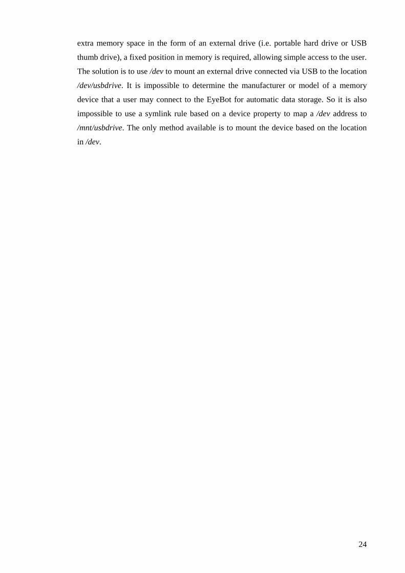
Two programs were created to perform testing of the GPS library and also to
demonstrate use of the library to users. The first is getGPSdata.c, which displays all
information from the GPSdata_t structure, either statically with the user able to push a
button to update the display with a new reading from the GPS, or a selection via key
press will call an update to be displayed to screen every 2 seconds (Figure 7 shows an
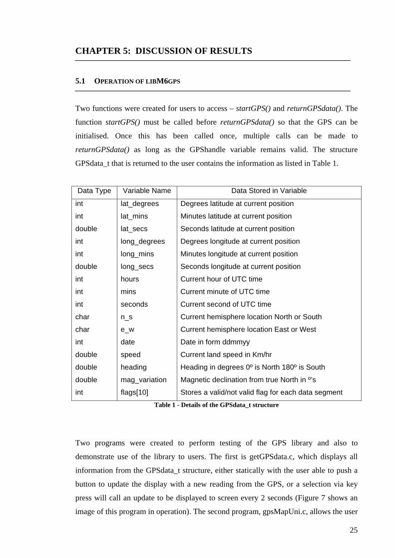
image of this program in operation). The second program, gpsMapUni.c, allows the user
25
to see their position within the University of Western Australia via a satellite map
obtained from Google earth (Google 2008). This program allows either the user to see
only their current position on the screen, or they have the option of including a trace so
they may see their location over time (Figure 8 shows an image of this program in
operation).
Figure 7 - One reading of the getGPSdata test-demo program
The libM6gps library allows software designers to easily integrate GPS positioning into
their programs, allowing efficient and effective positioning of a robot where a GPS
signal is available. The function returnGPSdata() is able to return a new set of data
faster, in less time than it takes the GPS to print out the next reading. In this way
maximum availability of the required information is possible. In maximising this return
speed, some information which may be useful is not retrieved, including information
indicative of position accuracy and altitude above sea level. This has been omitted
deliberately since it is not likely to be needed in the majority of cases and doing so
speeds up the processing time by over double since processing of multiple data
sentences is not needed when omitting these readings.
26
Figure 8 - View of gpsMapUni in opperation, note the yellow square indicating users position is an
extreme exageration. The standard size is 3x3 pixels 5.2 OPERATION OF LIBM6LCD
With the completion of the writers work libM6lcd, is now able to print all readable
characters from the standard ASCII set in a font twice the size of the standard text font.
Functions have been written to allow all commands that print text to the LCD screen to
print to it in the new large font. This is achieved by setting the new mode
LARGE_FONT with the command LCDSetTextMode(). The cursor positions for both
the large and small text are controlled separately with the set and get cursor position
functions.
It is left up to the programmer to ensure that the cursor positions are maintained such
that small and large text is not written to the screen in the same position. This is done
deliberately as it would take more processor time if the library was responsible for
ensuring text did not clash on screen. It also provides complete separation of the two
text buffers so that cursor positions for one size are not affected by the cursor position
of the other, thus the layout of text on screen can be achieved with certainty. This is
regardless of whether or not the programmer has been diligent in ensuring that there are
no clashes of text on screen. If there is a text clash on screen, the regular text size will
be displayed over the top of the large text. An example of this is seen in Figure 9.
27
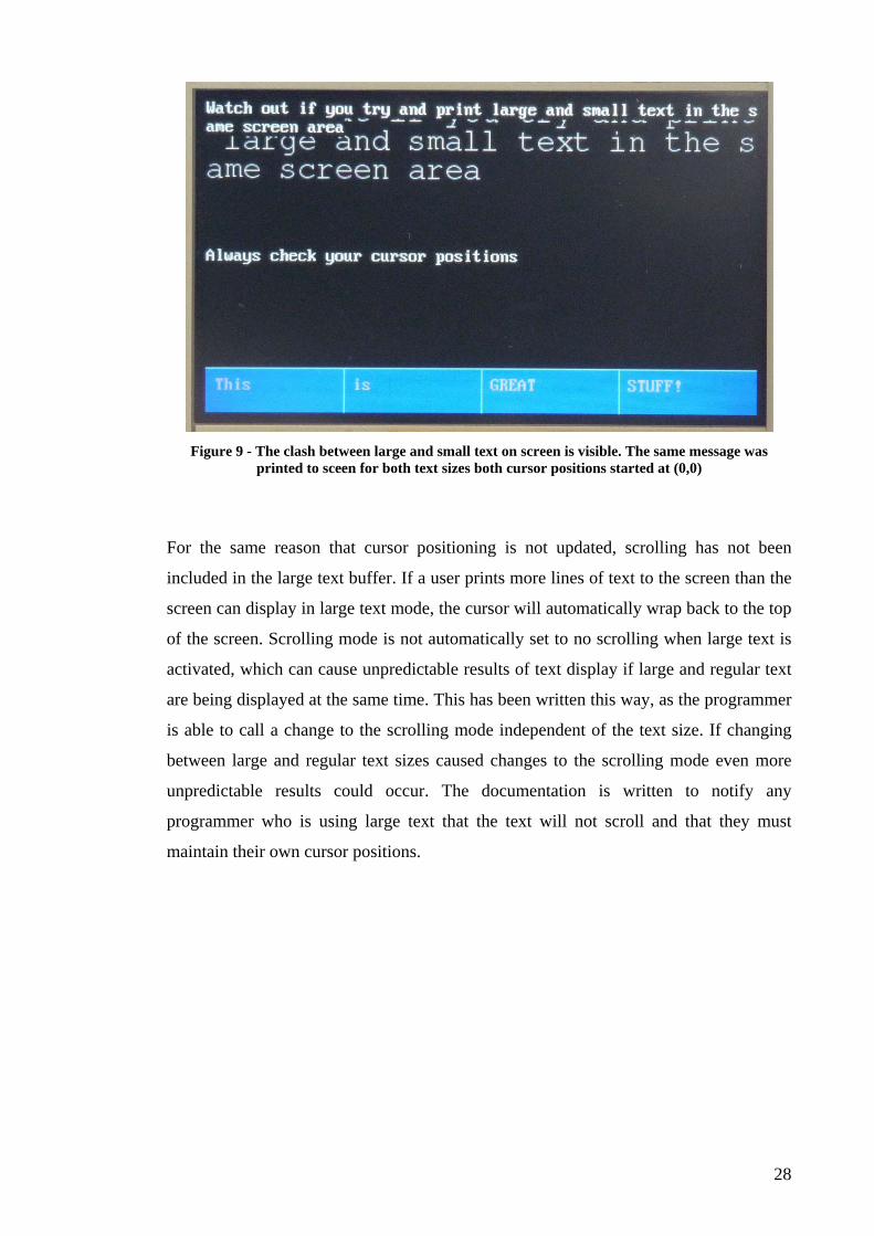
Figure 9 - The clash between large and small text on screen is visible. The same message was
printed to sceen for both text sizes both cursor positions started at (0,0)
For the same reason that cursor positioning is not updated, scrolling has not been
included in the large text buffer. If a user prints more lines of text to the screen than the
screen can display in large text mode, the cursor will automatically wrap back to the top
of the screen. Scrolling mode is not automatically set to no scrolling when large text is
activated, which can cause unpredictable results of text display if large and regular text
are being displayed at the same time. This has been written this way, as the programmer
is able to call a change to the scrolling mode independent of the text size. If changing
between large and regular text sizes caused changes to the scrolling mode even more
unpredictable results could occur. The documentation is written to notify any
programmer who is using large text that the text will not scroll and that they must
maintain their own cursor positions.
28
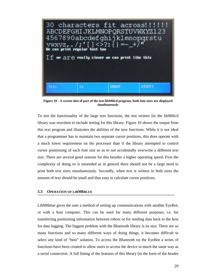
Figure 10 - A screen shot of part of the test-libM6lcd program, both font sizes are displayed
simultaneously
To test the functionality of the large text functions, the test written for the libM6lcd
library was rewritten to include testing for this library. Figure 10 shows the output from
this text program and illustrates the abilities of the new functions. While it is not ideal
that a programmer has to maintain two separate cursor positions, this does operate with
a much lower requirement on the processor than if the library attempted to control
cursor positioning of each font size so as to not accidentally overwrite a different text
size. There are several good reasons for this besides a higher operating speed. First the
complexity of doing so is unneeded as in general there should not be a large need to
print both text sizes simultaneously. Secondly, when text is written in both sizes the
amount of text should be small and thus easy to calculate cursor positions.
5.3 OPERATION OF LIBM6BLUE
LibM6blue gives the user a method of setting up communications with another EyeBot,
or with a host computer. This can be used for many different purposes, i.e. for
transferring positioning information between robots or for sending data back to the host
for data logging. The biggest problem with the Bluetooth library is its size. There are so
many functions and so many different ways of doing things, it becomes difficult to
select any kind of “best” solution. To access the Bluetooth on the EyeBot a series of
functions have been created to allow users to access the device in much the same way as
a serial connection. A full listing of the features of this library (in the form of the header
29
file) is listed in Appendix 1. The library has been written to utilise the rfcomm layer of
the BlueZ stack. The reason for this is that connections may need to be maintained for a
long duration. The rfcomm layer is better than the l2cap layer for this task (Huang
2005).
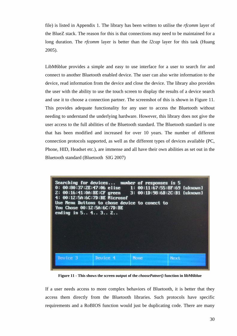
LibM6blue provides a simple and easy to use interface for a user to search for and
connect to another Bluetooth enabled device. The user can also write information to the
device, read information from the device and close the device. The library also provides
the user with the ability to use the touch screen to display the results of a device search
and use it to choose a connection partner. The screenshot of this is shown in Figure 11.
This provides adequate functionality for any user to access the Bluetooth without
needing to understand the underlying hardware. However, this library does not give the
user access to the full abilities of the Bluetooth standard. The Bluetooth standard is one
that has been modified and increased for over 10 years. The number of different
connection protocols supported, as well as the different types of devices available (PC,
Phone, HID, Headset etc.), are immense and all have their own abilities as set out in the
Bluetooth standard (Bluetooth_SIG 2007)
Figure 11 - This shows the screen output of the choosePatner() function in libM6blue
If a user needs access to more complex behaviors of Bluetooth, it is better that they
access them directly from the Bluetooth libraries. Such protocols have specific
requirements and a RoBIOS function would just be duplicating code. There are many
30
open source program that deal with aspects of the Bluetooth standard, such as the
OBEX push command. If these are needed in the future, it should not be difficult to
access some of these on the EyeBot. Regrettably, the writer did not have time to test
this. In conclusion, libM6blue provides an easy to use library of functions that spares
the standard user from needing to understand the many layers of Bluetooth. The more
advanced user with specific requirements may find a better solution by using different
layers of the BlueZ stack.
5.4 USING UDEV TO MAP DEVICES TO FIXED LOCATIONS
To allow programmers to log data to an external device a file containing the new
symlink has been added to the /etc/udev/rules.d folder. This rule maps the location in
memory /dev/sda1 to the /mnt/usbdrive location. As stated before, if multiple memory
devices are connected to the EyeBot, the first will be mapped to sda1 and the second to
/dev/sdb1 etc. Thus it is necessary that the user connect their desired external memory
device first before any other memory devices are connected to ensure this is the device
written to. This has been noted in documentation, unfortunately since no information
can be determined (due to the near infinite possible types of external memory devices
that could be connected) this cannot be more reliably assigned. If the user wishes only
to use one memory device for logging, they may create their own symlink rule based on
their device properties to ensure they write to the correct memory device.
5.5 OBTAINING ACCESS TO CODE DEVELOPED
All code written for the EyeBot project by the writer, is currently available on the server
r2d2, residing in the Electrical Engineering building at the University of Western
Australia. It is stored on this machine in a svn repository. The software has also been
uploaded onto the Mechanical Server as part of this paper. A Twiki is available for help
on how to retrieve the software.
31
5.6 DIFFICULTIES ENCOUNTERED DURING THE PROJECT
While being an exciting project to work on, the EyeBot can be a frustrating controller to
work on (this is mainly at the hardware level. The portions of the RoBIOS library that
have already been written do work quite easily). There are several causes for this
problem. Firstly the hardware is complex. It is almost impossible to get a probe onto
any area of interest (data bus, LCD line etc.) as most of the contacts on all of the boards
are obscured because they are all sandwiched together. This is great for making a
compact robot, but not for conducting debugging. Secondly, the deeper elements of
Linux code, i.e. kernel drivers, are often not well documented and hard to follow. It
takes a lot of research into certain components to find out how to use them and further
work to find out how best to use them.
Being a striped down version of Linux, some commands and tools simply aren’t there in
order to save space. While this is understandable, it is also very frustrating at times. The
writer was forced to spend a lot of time finding different commands or tools that were
available on the controller. These problems are not insurmountable, they just take a lot
more time to sort out than would be expected.
32
CHAPTER 6: CONCLUSIONS AND RECOMMENDATIONS 6.1 CURRENT STATE OF THE ART
The problem with many designs in research today is that these designs stay as research;
they are unlikely to ever be produced on a commercial scale. Reasons for this include
the cost of components that go into these designs, i.e. the sick laser finders found in
several designs on localisation and mapping (Nguyen et al. 2006), as well as the
dependence on specific hardware such as the XBC (LeGrand 2005). Once such a design
is produced, any changes in the hardware availability means that device can no longer
be made and the software is rendered useless because it is so target specific (i.e. the
XBC).
The EyeBot has an advantage that it has its own subset of functions that can move from
version to version. The software may need to be rewritten (but always in C, which is a
well known language) if a new hardware system is chosen in the future. The advantage
of using Linux for its operating system is that it can easily be updated by downloading
the latest version of the Internet, where regular updates are available. This provides the
ability to keep the operating system up to date as technology advances with relative
ease. Further to this there has been a wide range of robots that have been developed
using the previous controller. This provides a large amount of background design
information for future designs to look at successful implementations of software written
for this specific device.
It may not be possible to perform SLAM algorithms with the EyeBot M6 due to the size
of the Xilinx FPGA incorporated in its design. However, the writer believes that this is a
much better path to follow with cheap sensors and better processing abilities, rather than
the brute force approach of expensive peripherals. The rise of digital photography has
lead to a huge drive for continuous improvement in CCD technology as well as price
drops. In the writers opinion, this will continue to promote image processing algorithms
as a better solution to SLAM implementation. SLAM will hopefully present a solution
to the problems of human interaction with robots, as well as providing a framework to
increase a robots ability to work autonomously. Such algorithms are a useful tool for
mobile robots, but should only be part of the functionality.
33
6.2 THE EYEBOT M6
The EyeBot development is divided into two separate areas of development. The image
processing component is progressing independent of the writers research, looking at
designs on the Xilinx FPGA. It is this research that will hopefully lead us to new
methods of image processing useful to mobile robotics. The writers focus has been on
ensuring that the EyeBot M6 is capable of fulfilling its role as a mobile robot. As part of
this work the writer has presented several new functions to include in the RoBIOS
library.
6.3 FUTURE WORK
HID (Human Interface Device) drivers have been installed on the EyeBot. These
properly detect devices such as simple USB keyboards (running dmesg from Console
verifies that the kernel creates the appropriate device events), however there is little
ability to utilise them without access to Console, which would be difficult to implement.
A requirement for this is debatable since Console is available through serial or Ethernet
to any computer connected to the network at a much more reasonable resolution. The
writer was unable to re-write libM6radio using libM6blue, implementing this in the
future will allow an easy to use wireless network for the EyeBot (Wilke & Bräunl
2001).
The EyeBot M6 now has a near complete RoBIOS library ready for use. Still currently
being implemented are the functions for the cameras. These are currently being written
as part of research projects conducted by others. Many hours both by students and
technicians working for the Electrical Engineering department at the University of
Western Australia have now been spent on the hardware and software design of this
robot controller. Hopefully many more will be spent utilising it for its design purpose.
34
REFERENCES
Gumstix Connex 400xm-bt. Available from: http://www.kaboodle.com/reviews/gumstix-connex-400xm-bt [20 October 2008].
Adamchuk, VI 2001, 'Untangling the GPS Data String', University of Nebraska
Cooperative Extention EC 01-157 - Precision Agriculture. Blackham, B 2006, The Development of a Hardware Platform for Real-time Image
Processing, The University of Western Australia. Bluetooth & SIG, Bluetooth.com | Core System Architecture, Bluetooth SIG, Inc.
Available from: www.bluetooth.com [15 July 2008]. Bluetooth_SIG 2007, 'Bluetooth Core V2.1 + EDR', vol. 3. Bräunl 2006, 'Introduction to Emebedded Systems', in Embedded Systems, The
University of Western Australia. Available from: http://student.ee.uwa.edu.au/units/elec2303/lectures/Lectures%20Notes/ES1-Intro.pdf.
Bräunl, T 2003, Embedded Robotics - Mobile Robot Design and Applications with
Embedded Systems, Springer, Berlin. Churn, D 2008, RoBIOS Routines for the Eyebot M6, UWA. Drake, D, Writing udev rules, Daniel Drake. Available from:
www.reactivated.net/writing_udev_rules.html [20 August 2008]. Google, 2008, Google Earth, Google [5th September 2008]. Grey, W 1951, 'A Machine that Learns', Scientific American no. August 1951, pp. 60-
63. Gumstix, 2008, gumstix.com - way small computing, DigiGlyphs. Available from:
http://gumstix.com/store/catalog/product_info.php?products_id=155 [10 September 2008].
Hintermann, M 2007, Operating System Components for an Embedded Linux System,
Technische Universitat Munchen. Honda Motor Co., L, Honda Worldwide | ASIMO, Honda Motor Co., Ltd. Available
from: http://world.honda.com/ASIMO [10 September 2008]. Huang, A 2005, The Use of Bluetooth in Linux and Location Aware Computing,
Massachuesetts Institute of Technology.
35
iRobot & Corporation, iRobot. Available from: http://store.irobot.com/home/index.jsp [15 March 2008].
Kroah-Hartman, G 2003, 'udev - A Userspace Implementation of devfs', in Linux
Symposium, Ottawa, Canada, pp. 263-271. LeGrand, R, Machulis, K., Miller D.P., Sargent, R. & Wright, A. 2005, 'The XBC: a
Modern Low-Cost Mobile Robot Controller', in IEEE/RSJ International Conference on Intelligent Robots and Systems, Austin, TX, USA, pp. 2896-3900.
Mathew, R, The REV Project, The REV Project. Available from:
www.therevproject.com [11 July 2008]. Nguyen, V, Harati, A, Martinelli, A & Siegward, R 2006, 'Orthogonal SLAM: a Step
toward Lightweight Indoor Autonomous Navigation', in International Confrence on Intelligent Robots and Systems, Beijing China, pp. 5007-5012.
Wilke, P & Bräunl, T 2001, 'Flexible wireless communication network for mobile robot
agents', The Industrial Robot, vol. 28, no. 3, pp. 220-232. Wolf, D, Holanda, J, Bonata, V, Peron, R & Marques, E 2007, 'An FPGA-Based Mobile
Robot Controller', in 3rd Southern Conference on Programmable Logic, Mar del Plata, pp. 119-124.
36
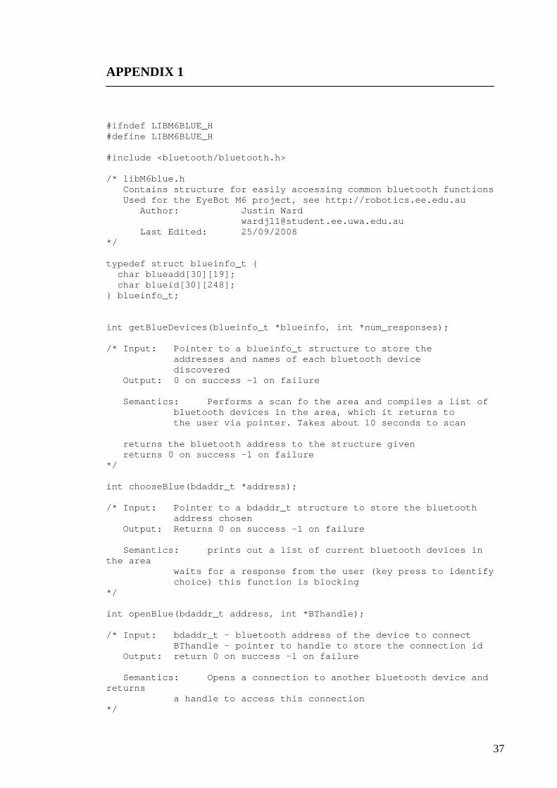
APPENDIX 1 #ifndef LIBM6BLUE_H #define LIBM6BLUE_H #include <bluetooth/bluetooth.h> /* libM6blue.h Contains structure for easily accessing common bluetooth functions Used for the EyeBot M6 project, see http://robotics.ee.edu.au Author: Justin Ward [email protected] Last Edited: 25/09/2008 */ typedef struct blueinfo_t { char blueadd[30][19]; char blueid[30][248]; } blueinfo_t; int getBlueDevices(blueinfo_t *blueinfo, int *num_responses); /* Input: Pointer to a blueinfo_t structure to store the addresses and names of each bluetooth device discovered Output: 0 on success -1 on failure Semantics: Performs a scan fo the area and compiles a list of bluetooth devices in the area, which it returns to the user via pointer. Takes about 10 seconds to scan returns the bluetooth address to the structure given returns 0 on success -1 on failure */ int chooseBlue(bdaddr_t *address); /* Input: Pointer to a bdaddr_t structure to store the bluetooth address chosen Output: Returns 0 on success -1 on failure Semantics: prints out a list of current bluetooth devices in the area waits for a response from the user (key press to identify choice) this function is blocking */ int openBlue(bdaddr_t address, int *BThandle); /* Input: bdaddr_t - bluetooth address of the device to connect BThandle - pointer to handle to store the connection id Output: return 0 on success -1 on failure Semantics: Opens a connection to another bluetooth device and returns a handle to access this connection */
37
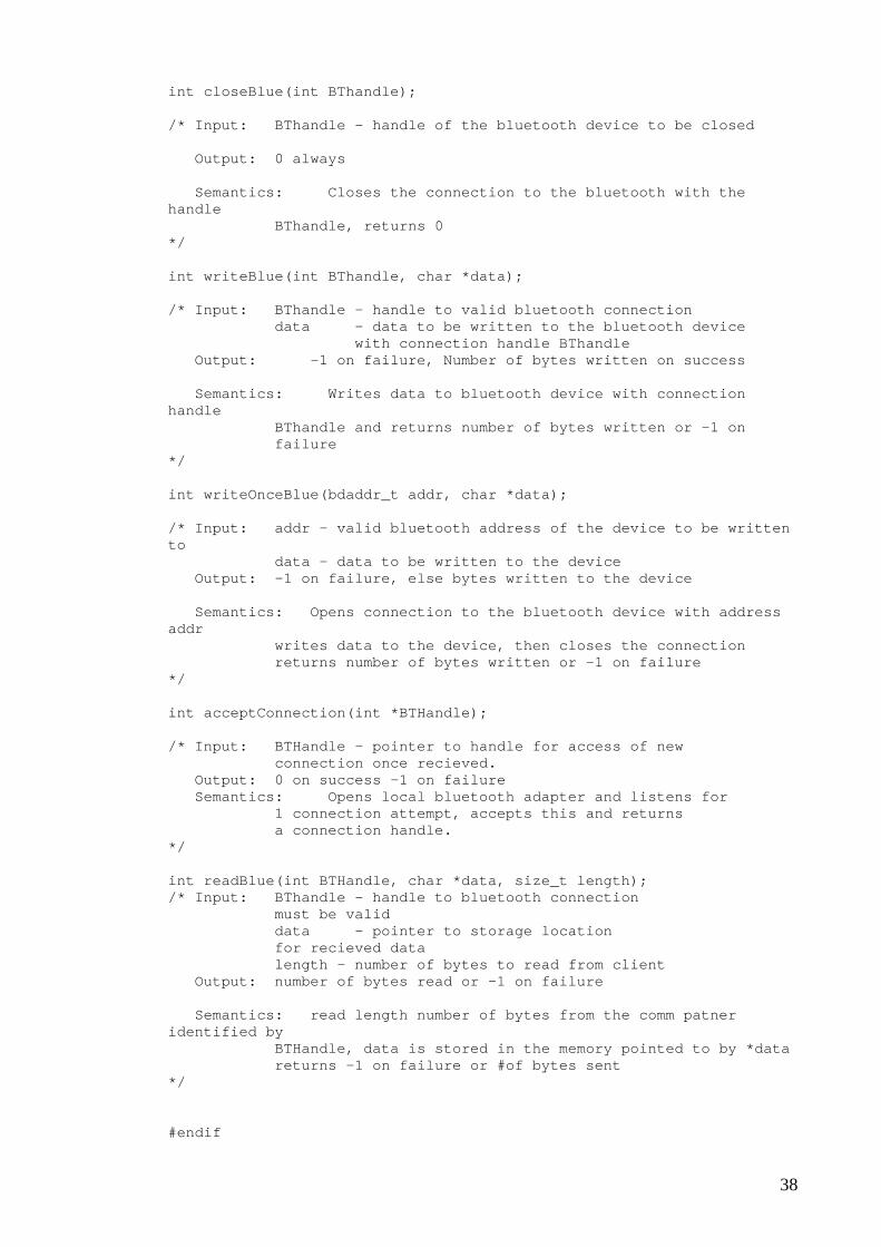
int closeBlue(int BThandle); /* Input: BThandle - handle of the bluetooth device to be closed Output: 0 always Semantics: Closes the connection to the bluetooth with the handle BThandle, returns 0 */ int writeBlue(int BThandle, char *data); /* Input: BThandle - handle to valid bluetooth connection data - data to be written to the bluetooth device with connection handle BThandle Output: -1 on failure, Number of bytes written on success Semantics: Writes data to bluetooth device with connection handle BThandle and returns number of bytes written or -1 on failure */ int writeOnceBlue(bdaddr_t addr, char *data); /* Input: addr - valid bluetooth address of the device to be written to data - data to be written to the device Output: -1 on failure, else bytes written to the device Semantics: Opens connection to the bluetooth device with address addr writes data to the device, then closes the connection returns number of bytes written or -1 on failure */ int acceptConnection(int *BTHandle); /* Input: BTHandle - pointer to handle for access of new connection once recieved. Output: 0 on success -1 on failure Semantics: Opens local bluetooth adapter and listens for 1 connection attempt, accepts this and returns a connection handle. */ int readBlue(int BTHandle, char *data, size_t length); /* Input: BThandle - handle to bluetooth connection must be valid data - pointer to storage location for recieved data length - number of bytes to read from client Output: number of bytes read or -1 on failure Semantics: read length number of bytes from the comm patner identified by BTHandle, data is stored in the memory pointed to by *data returns -1 on failure or #of bytes sent */ #endif
38