Embed Size (px)
Citation preview
Roboboat Technical Report Georgia Tech Marine Robotics
1
Roboboat 2020: Technical Design Report
Ali Kazmi, Anshul Sinha, Anthony Velte, Coline Ramee, Daniel Foreman, Domenic DiCarlo, Edward Jahoda, Eric Fu, Eric Phan, Jeffery
Pattison, Jose Adrande, Justin Chau, Luke Dorrian, Maddi Schlaff, Mary Catharine Martin, Matt Gilmartin, Patrick Meyer, Praneeth
Eddu, Rahul Rameshbabu, Robert Kuramshin, Rohit Vepa, Sean Fish, Trevor Daino, Tyler Campbell, Vincent Chow
Georgia Tech Marine Robotics Group, Georgia Institue of Technology Atlanta, Georgia, United States
I. Abstract Following the 2019 Roboboat competition, Georgia Tech Marine Robotics (GTMR) aimed to improve
primarily upon hardware reliability and software robustness. The software implementation was made
more resource-efficient and task-adaptable through on-demand processing. The existing LIDAR system
was augmented with a camera-based neural-network classifier to create a robust sensing system. Data
collected during on-water tests was used to generate a dynamic boat model. This model could be used
in simulation to quickly and reliably test sensing, control, and competition-task related algorithms,
decreasing development times. Redundant GPS sensors were used to improve the boat’s state estimation
and allow the boat to function even if one of the GPS units failed to gain a lock, a crippling issue during
the 2019 Roboboat competition. In conjunction with the boat model, a Kalman filter state estimator was
applied to the boat’s multiple positioning sensors to perform sensor-fusion based state estimation. The
boat underwent a redesign as well, reducing its weight, increasing its hydrodynamics, and maintaining
its stable catamaran design. As part of the redesign, a holonomic thrust configuration was used in place
of the previous design’s differential thrust to improve maneuverability, which offered a good tradeoff
between complexity and scoring opportunity. To capitalize on high-scoring events, GTMR began work
on both a drone and a hydrophone. A commercial drone was modified to carry and drop payloads for
the object delivery event and a hydrophone system concept was developed to sense acoustic-beacons for
the docking event.
II. Competition Strategy There were many lessons learned at Roboboat 2019. After numerous technical difficulties which
prevented testing at the competition, the team aimed to improve primarily upon hardware reliability and
software robustness. Seeing how many other teams faced low-level, hardware and interfacing issues as
well, Georgia Tech Marine Robotics (GTMR) decided that focusing on reliability and robustness over
breadth of scope would give GTMR a competitive advantage over teams without similar firm
fundamentals, and offer a strong future basis for improvements.
A. Software
Roboboat 2019 was the first time the team used a ROS-based software for its Roboboat vehicle.
The software was loosely integrated with the Virtual RobotX (VRX) simulator to test task logic, but the
integration was not mature and differences in scale between the WAM-V and the Roboboat vehicle
caused issues when tuning task parameters. Tasks that worked in simulation sometimes failed in the real-
world.
The VRX competition held at the end of Fall 2019 presented an opportunity to improve the
software robustness and integration with the VRX simulator. The VRX competition had two tasks in
common with Roboboat: a docking challenge and a navigation challenge in which the vehicle had to
cross gates marked by green and red pillar buoys and avoid obstacles marked by buoys. Code developed
for these VRX tasks would be directly applicable to Roboboat, providing a great testbed for the software.
Hence, code used for Roboboat 2019 was used as the starting point for the VRX competition and
Roboboat Technical Report Georgia Tech Marine Robotics
2
compatibility with the Roboboat vehicle was a constraint kept in mind while developing code for the
VRX competition.
The 2019 Roboboat implemented a dual-thruster design that relied on differential thrust to turn.
However, as several VRX tasks required very precise positioning and station-keeping which were
difficult to achieve with a dual-thruster design, the team decided to implement holonomic control for the
simulated competition. The team had observed that other teams had implemented holonomic control for
their Roboboat vehicles by using 4 thrusters, so we knew it could be done but the team was not sure how
much it would increase the complexity and whether it was worth it for the Roboboat competition, which
does not require precise station-keeping. From a mechanical perspective, adding two thrusters to the
current Roboboat design would be easy due to the design’s modular 80/20 rails on the underside of the
pontoons. The team decided to implement a 4-thruster X-configuration in VRX and to evaluate its results
to decide whether it was worth using this propulsion system on the actual vehicle. This modification was
found to be relatively easy to implement from a software perspective, greatly improving the trajectory
following behavior and simplifying the docking task. Seeing the change as a net benefit despite its
increase in complexity, the team opted to implement a holonomic control configuration for the Roboboat
2020 boat.
A purely LIDAR-based object detection method was used in 2019. This method caused an issue
on Course Bravo and Charlie as the two navigation channels were close to each other and about the same
length apart as the gate length. Without a way to discriminate between red and green buoys, the software
picked the wrong two buoys to go through. Camera image-recognition would have easily been able to
distinguish the appropriate buoy. However, camera data-collection was only implemented mid-
competition and was not mature enough to recognize and classify the buoys based on their unique colors.
That same summer, GTMR competed at RoboSub, developing image recognition neural network
algorithms and applying them with great success. To improve task-logic robustness, the team combined
the sub’s camera-based perception with the boat’s software stack.
B. Sensors
The team had many issues in 2019 with its Novatel GPS sensor. It would often fail to get a lock,
wasting precious on-water time as it was the only positioning sensor for the boat and all autonomous
routines required its data. To create redundancy and potentially improve precision, an ArduSimple RTK
GPS sensor was integrated in conjunction with the Novatel GPS.
The VLP16 LIDAR works well for object detection, but during the 2019 competition it caused
internal networking issues due to a setting the team had not been aware of which had been reset a year
prior. The team decided to put an emphasis on documenting this sensor’s configuration to prevent further
incidents.
C. Boat modeling
One area of improvement identified after the 2019 Roboboat competition was on-water testing.
This was made particularly clear during the 2019 competition. Due to numerous issues that could have
been prevented with frequent testing, the team spent the vast majority of the competition week
unexpectedly debugging core code and not working on adapting task-solutions. GTMR does not have
easy access to convenient testing locations since the school pool is indoors (no GPS signal) and the
closest testing location is a lake 30 minutes away. This distance makes frequent on-water tests difficult.
To mitigate testing deficits, an emphasis was placed on creating an accurate model for the boat so that
the majority of tasks and functionalities could be tested in simulation, allowing the time-consuming real-
world tests to be used only for final validation. The VRX simulator only contains a WAM-V model that
is a much larger vehicle than the one used for Roboboat. Hence, the team decided to dedicate significant
efforts to the development of a Roboboat vehicle model and its integration in VRX.
Roboboat Technical Report Georgia Tech Marine Robotics
3
D. Boat Redesign
The 2020 Roboboat underwent a re-design, improving upon the 2019 boat. The 2019 boat, while
still fully operational, would be around 3 years old by the 2020 competition, and was drastically
oversized after a modification early 2019 nearly halved its weight [1]. Additionally, the club-members
who had previously created and fiberglassed the pontoons would be graduating by Spring 2020 and the
knowledge they had on creating pontoons would be lost if it were not documented/reproduced. For these
reasons, a boat redesign was started at the end of 2019 for the 2020 competition.
The improved design focused primarily on stability, the ability to maneuver precisely,
modularity, weight, and manufacturability. A catamaran design was chosen, as it was simple but stable.
Even though it would be unable to move rapidly in the water, and may have been larger than a monohull
boat, it was chosen over alternatives due to manpower restrictions on the hardware team and a desire to
have reliable sensing, which is aided by boat stability. The 2020 design’s main improvement was in the
pontoons, as the 2019 boat’s modular rail and containerized electronics systems already worked well
and did not need to be significantly redesigned [1]. A more profiled pontoon body was selected for
fabrication, even though fiberglassing the sharp corners and complex geometry was a greater technical
challenge than the alternative cylindrical pontoons of the 2019 Roboboat. The additional complexity was
thought to be manageable due to the experience some members had from fiberglassing pontoons on the
previous boat, as well as connections to contacts within the Georgia Tech Design-Build-Fly (DBF) and
Solar Racing clubs, both of which fiberglassed frequently and would be able to provide mentorship and
fiberglassing facilities if needed. This profile improvement would significantly reduce overall weight,
length, and the frictional losses created by the brick-like shape of the 2019 pontoons, giving the new
boat a competitive edge in thrust-to-weight ratio, maneuverability, and docking.
E. UAV/Drone
In order to score points in the object delivery task, an Unmanned Aerial Vehicle (UAV) was
constructed. The UAV needed to be big enough to carry an unspecified payload but small and stable
enough to launch from the boat. The UAV also needed its own sensing system to identify the delivery
platform. The delivery strategy was for the UAV to lift off from the boat after the boat finished docking
and while in proximity of the delivery platform, use its attached camera to detect and land on the delivery
platform, scoring points for the objects it delivered. To ensure that the drone would be recoverable if it
fell into the water, the frame of the UAV incorporated floatation devices on the landing gear, permitting
water landings if needed.
F. Hydrophone Array
As hydrophone-related events are typically a competition event that annually provides high-
scoring opportunities, GT Roboboat sought to capitalize on this opportunity and create a hydrophone
sensing system. From a cursory attempt 3 years ago to create a hydrophone system, GT Roboboat owned
3 Telodyne TC 4013 Hydrophones, which were determined to be suitable for hydrophone localization.
Using these 3 hydrophones as a base, a hydrophone pre-processing, sampling, and beacon-locating
algorithm were conceptualized from other similar, working systems from other teams and industry
techniques. III. Design Creativity
A. Software Architecture
The tasks in the Roboboat competition are varied, but there are many commonalities between
them. For instance, the navigation channel, winding navigation channel with obstacles and speed gate
all require the identification of gates marked by green and red buoys. On the other hand, behaviors that
are required for some tasks are superfluous or a hindrance in other tasks: obstacle avoidance must be
Roboboat Technical Report Georgia Tech Marine Robotics
4
active in the winding navigation channel and the obstacle field but turned off when docking. ROS is a
modular framework but there is no easy method to turn nodes on or off programmatically. Hence, the
team needed to design a method in the software that would allow behaviors to be modular at runtime.
As detailed in the 2019 technical report [1] only the controller, i.e. the node in charge of
translating a command message to motor commands, could be switched in order to handle different types
of command messages (path, waypoint, pose, etc.). The computationally expensive perception
algorithms were running even when they were not needed, and when different perception behaviors were
required, such as for the docking task, perception and task logic were performed in the same node. This
was making the code confusing, difficult to debug and difficult to hot swap.
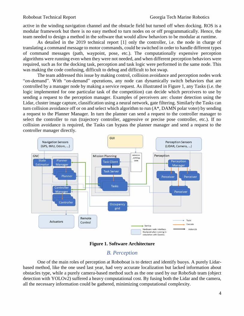
The team addressed this issue by making control, collision avoidance and perception nodes work
“on-demand”. With “on-demand” operations, any node can dynamically switch behaviors that are
controlled by a manager node by making a service request. As illustrated in Figure 1, any Tasks (i.e. the
logic implemented for one particular task of the competition) can decide which perceivers to use by
sending a request to the perception manager. Examples of perceivers are: cluster detection using the
Lidar, cluster image capture, classification using a neural network, gate filtering. Similarly the Tasks can
turn collision avoidance off or on and select which algorithm to run (A*, DAMN polar voter) by sending
a request to the Planner Manager. In turn the planner can send a request to the controller manager to
select the controller to run (trajectory controller, aggressive or precise pose controller, etc.). If no
collision avoidance is required, the Tasks can bypass the planner manager and send a request to the
controller manager directly.
Figure 1. Software Architecture
B. Perception
One of the main roles of perception at Roboboat is to detect and identify buoys. A purely Lidar-
based method, like the one used last year, had very accurate localization but lacked information about
obstacles type, while a purely camera-based method such as the one used by our RoboSub team (object
detection with YOLOv2) suffered a heavy computational cost. By fusing both the Lidar and the camera,
all the necessary information could be gathered, minimizing computational complexity.
Roboboat Technical Report Georgia Tech Marine Robotics
5
The method to identify buoys uses three perceivers. The first perceiver clusters LIDAR points
using the DBSCAN algorithm [2]. The second perceiver subscribes to the cluster positions in the LIDAR
frame and maps them to pixels in the camera frame. It then publishes the subset of the image
corresponding to the cluster. The third perceiver subscribes to the cropped images and uses a neural
network implemented using Tensorflow [3]. This method was initially implemented for the VRX
competition and yielded great results without increasing the computational complexity excessively.
C. Sensors and Simulation Modeling
With 3 primary sensors for positioning (2 GPS units, 1 IMU), there was a significant push
towards improving the boat’s state estimation capabilities. In prior years, the GPS data was used to
determine the boat’s X-Y location relative to a starting point using a planar approximation of the earth’s
surface from the Latitude-Longitude positioning. The IMU’s magnetometer was used for heading control
by assuming the readings would be oriented primarily towards the magnetic poles of the Earth. Each
sensor reading was used by the overarching state estimator after being passed through a low-pass filter,
irrespective of the sensor error, with the sensor reading being the assumed maximum likelihood estimate
of the physical property.
A Kalman filter improved upon the existing state estimation by accounting for error and multiple,
sometimes redundant, sensors. Kalman filters are a well-known algorithm which can converge to
approximate unseen states in a system extrapolated from known sensor readings, uncertainties, and a
system model. The IMU provided its own variance measurements, and the GPS units all were specified
to have known positional uncertainty, allowing the controls team to tune the uncertainty of the boat
model, striking a balance between the expected model predictions and the sensor readings to ensure that
the filter would converge to the true system state. The state prediction was updated every time a new
sensor reading was processed, or a thrust command was sent to the boat to move.
A dynamic model was required for the Gazebo simulation and the Kalman filter. This model
needed to account for surge acceleration, sway acceleration, and yaw acceleration given the current surge
velocity, sway velocity, yaw rate, and motor commands. To create such a model, the Roboboat team
collected an hour of data from the 2019 Roboboat while it performed a procedurally-determined variety
of turns and straightaways, both forwards and backwards, to excite a wide-range of the boat’s dynamics.
The 2019 boat was used as a proof of concept while the 2020 Roboboat was being designed and
fabricated. Although a new model would have to be created for the new design, this proof of concept
could be integrated with the simulator and state-estimator for testing.
The equations that were used to model the dynamics of the boat are based on Fossen's 3DOF
equations of motion [4]. These equations consist of hydro-dynamic derivatives, physical parameters, and
forces. The hydro-dynamic derivatives are learned using gradient based optimization, which optimizes
the hydrodynamic parameters to minimize the error of the predicted accelerations with respect to the
measured accelerations from the lake tests. The physical parameters were obtained by directly measuring
them from the boat. The forces were obtained through the data-sheet of the motors and the motor
commands given to the boat during the tests on the lake. Because learning hydrodynamic parameters
from noisy measurements can lead to an inaccurate dynamic model, the measurements are first smoothed
using a Kalman smoother [5]. The full implementation of the model is still ongoing.
D. Hydrophone Array
Although not currently complete, the proposed hydrophone system was designed to be self-
contained, and use all 3 of the team’s existing hydrophones. By creating a self-contained system, it could
easily be moved around the body of the boat for better placement, and reused on other platforms, such
as the Robosub and the VRX catamaran. Such a self-contained system is well suited for adapting
electrical isolation via an independent low-ripple power supply, a necessity for low-noise ADC
measurements. In a past attempt at creating hydrophones, the team discovered that using the voltage
Roboboat Technical Report Georgia Tech Marine Robotics
6
regulated output of an arduino while the arduino was generating PWM outputs resulted in significant
voltage level transients from the onboard regulator, necessitating the need for an external reference
voltage regulator for the hydrophones. Similar to other designs from other competitors [6,7,8], the
hydrophone array was designed to have a hardware pre-filtering and amplification step, which would
magnify the weak, piezeolectric pulses of each hydrophone and perform band-pass filtering around the
known pinger frequency of 25 to 40 Khz [9]. The removal of spurious frequencies, particularly high
frequency elements, is necessary to reduce signal distortion and aliasing that would skew frequency-
domain analyses. Although many hardware-based filters exist, the Butterworth filter is one of the easiest
to implement [10], leaving less opportunity for error over more complex filters while attenuating
unwanted frequencies well. For this reason, a Butterworth filter was chosen for the bandpass filter.
Although theoretically an 80 Khz sampling rate was the minimum rate necessary to avoid aliasing,
previous sampling at 110Khz proved inadequate and from the reports of other teams [6], a minimum of
500Khz is required to sample data well enough for signal detection. Further signal processing would
use an op-amp to multiply the transient signal voltage by a factor of 1000 and bias the signal such that
at rest the voltage was mid-range for the sampling ADC. This preprocessing step would allow the ADC
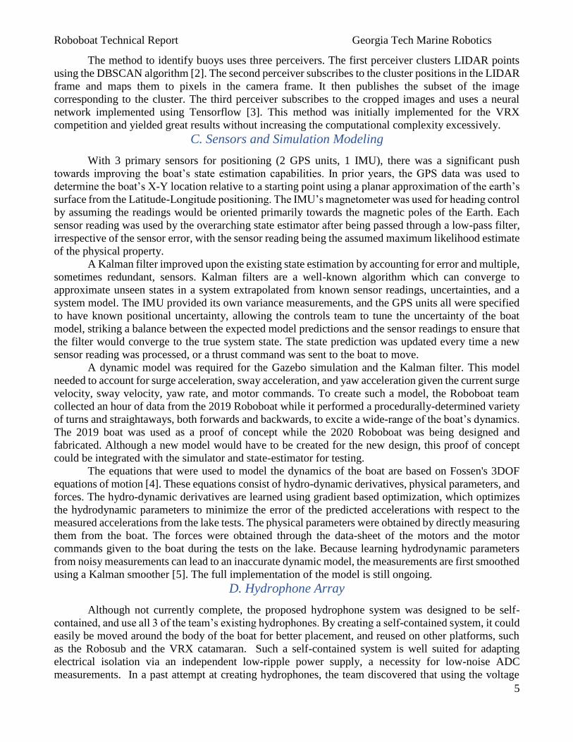
to sample the signal over its full range. The LTC2324-16, a 16 bit resolution with a 2 Msps sampling
rate over 4 channels was chosen for its ability to sample all 3 channels near synchronously with high
accuracy. Data collection would be offloaded to an onboard compute unit, most likely a Raspberry pi or
a Xilinx signal processing board (Figure 2) where the streaming data would be checked against a noise
floor threshold to see if a pulse had arrived. If the streamed data exceeded the threshold, the data would
be retained in memory for further processing, being discarded otherwise. The beacon-locating algorithm
utilizing this data is undecided and depends on the reliability and sensitivity of the hardware when
assembled.
Figure 2. Proposed hydrophone sampling circuitry
D. Drone/UAV
The UAV used a modified LJI ZD550 carbon fiber frame powered by a 5-cell lithium polymer
battery. This frame size coupled with the robust 5-cell battery enabled the UAV build to support not only
its own weight, but also the weight of a payload. A BeagleBone Blue with the Mission Planner software
was used as the flight controller, a GPS for localization, and a USB camera for image classification to
locate the target dock.
To land on the dock, the UAV could use the GPS coordinates of the dock as a waypoint, or the
UAV could take off near the dock and use an image classifier to identify the dock. The GPS waypoint
method did not constrain the vehicle to take off from just near the dock, allowing autonomous flight to
the waypoint at any location or time. However, if the delivery platform was at an unexpected location,
Roboboat Technical Report Georgia Tech Marine Robotics
7
the UAV would be unable to compensate, making the method error prone. The second method of using
an image classifier would mitigate this issue, but required more onboard computation and a USB camera
for imaging. To avoid interfering with the net, the camera addition needed to be offset from the center
of the drone. Additionally, an image-processing chip such as an Nvidia Jetson was required, which
would add weight and drain the battery faster, both decreasing the time of flight of the drone. However,
given its increased reliability and the drone’s large battery, the team decided that this was a more robust
and superior choice to hard-coded waypoints.
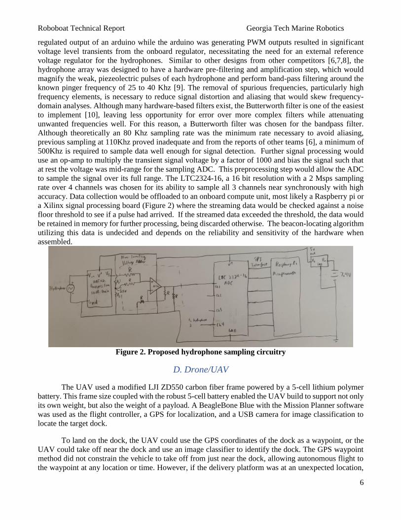
To ensure the UAV could float on water, its landing gear was replaced with a PVC pipe structure
encased in pool noodles. Pool noodles were chosen for floatation due to their cheap cost and ease of
modification. A buoyancy calculation involving the weight of the UAV (20.5N) with a factor of safety
of 1.2 was used to determine the length of pool noodles required. The weight force of the drone was
compared to the expected buoyant force of the pool noodles fully submerged to calculate a volume and
corresponding length required for flotation. A custom connector was designed to connect the PVC pipe
to the UAV and 3-D printed (Figure 3). To further guarantee the UAV’s safety, pool noodles were
wrapped over the connecting joints.
Figure 3. Drone CAD representation vs actual design.
E. Boat Redesign
The new design of the boat featured many novel endeavors, primarily in the new pontoons.
Although both the old 2019 and the new 2020 boat were catamaran designs, the new design is expected
to be far lighter thanks to lower pontoon mass. The pontoon mass was determined with a buoyancy
calculation based on the expected cumulative weight of the boat with a factor of safety of 3. The new
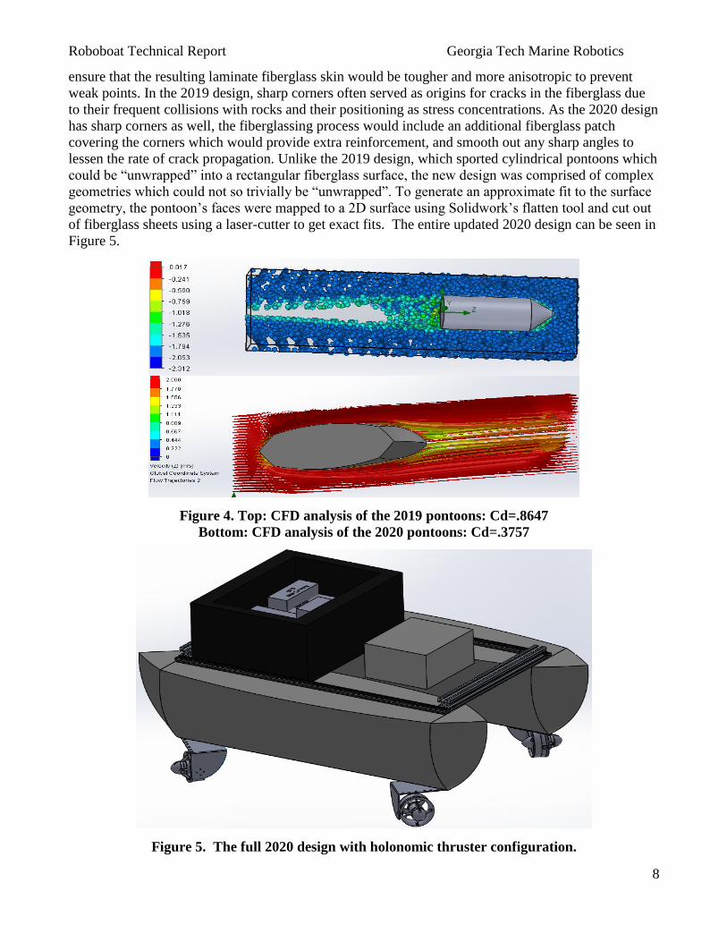
pontoons are also more hydrodynamic: CFD tests reveal that the new pontoons are expected to have
under half the coefficient of drag of the original pontoons, translating to greater speed and thrust
efficiency as seen in Figure 4. To ensure that the pontoons could maintain their shape after impacting
hard objects such as buoys or rocks, foam-filled fiberglassed pontoons were chosen over hollow
fiberglass shell or inflatable pontoon designs. With advice from Georgia Tech’s Design-Build-Fly
(DBF) group and GT Solar Racing, the decision was made to hand-fiberglass the pontoons, as the
alternative vacuum bagging technique would be harder and more expensive to implement, and the
pontoons could reasonably be fiberglassed in a 2-stage application, one over the flat top of the
pontoon, and one over the profiled hull. Unlike the 2019 boat, which had noticeable cracking in its
single fiberglass layer, a more durable dual layering would be used in 2020 with cross-thatching, to
Roboboat Technical Report Georgia Tech Marine Robotics
8
ensure that the resulting laminate fiberglass skin would be tougher and more anisotropic to prevent
weak points. In the 2019 design, sharp corners often served as origins for cracks in the fiberglass due
to their frequent collisions with rocks and their positioning as stress concentrations. As the 2020 design
has sharp corners as well, the fiberglassing process would include an additional fiberglass patch
covering the corners which would provide extra reinforcement, and smooth out any sharp angles to
lessen the rate of crack propagation. Unlike the 2019 design, which sported cylindrical pontoons which
could be “unwrapped” into a rectangular fiberglass surface, the new design was comprised of complex
geometries which could not so trivially be “unwrapped”. To generate an approximate fit to the surface
geometry, the pontoon’s faces were mapped to a 2D surface using Solidwork’s flatten tool and cut out
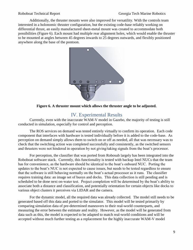
of fiberglass sheets using a laser-cutter to get exact fits. The entire updated 2020 design can be seen in
Figure 5.
Figure 4. Top: CFD analysis of the 2019 pontoons: Cd=.8647
Bottom: CFD analysis of the 2020 pontoons: Cd=.3757
Figure 5. The full 2020 design with holonomic thruster configuration.
Roboboat Technical Report Georgia Tech Marine Robotics
9
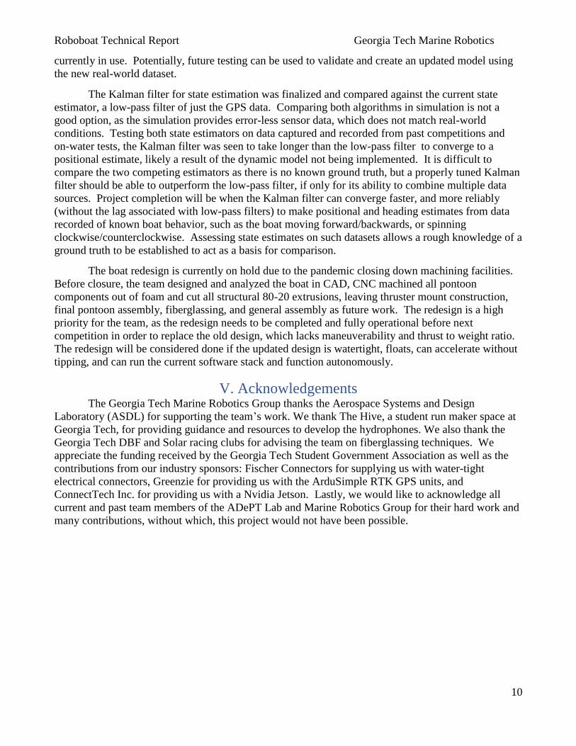
Additionally, the thruster mounts were also improved for versatility. With the controls team
interested in a holonomic thruster configuration, but the existing code-base reliably working on
differential thrust, an easily manufactured sheet-metal mount was created to accommodate both
possibilities (Figure 6). Each mount had multiple rear alignment holes, which would enable the thruster
to be mounted at angles between 45 degrees inwards to 25 degrees outwards, and flexibly positioned
anywhere along the base of the pontoon.
Figure 6. A thruster mount which allows the thruster angle to be adjusted.
IV. Experimental Results Currently, even with the inaccurate WAM-V model in Gazebo, the majority of testing is still
conducted in simulation, especially for control and perception.
The ROS services on demand was tested entirely virtually to confirm its operation. Each code
component that interfaces with hardware is tested individually before it is added to the code-base. As
perception on demand simply allows them to switch on or off as needed, all that was necessary was to
check that the switching action was completed successfully and consistently, as the switched sensors
and thrusters were not hindered in operation by not giving/taking signals from the boat’s processor.
For perception, the classifier that was ported from Robosub largely has been integrated into the
Roboboat software stack. Currently, this functionality is tested with backup Intel NUCs that the team
has for convenience, as the hardware should be identical to the boat’s onboard NUC. Porting the
updates to the boat’s NUC is not expected to cause issues, but needs to be tested regardless to ensure
that the software is still behaving normally on the boat’s actual processor as it runs. The classifier
requires training data: an image set of buoys and docks. This data collection is still pending and is
scheduled to be done next on-water test. Project completion will be determined by the boat’s ability to
associate both a distance and classification, and potentially orientation for certain objects like docks to
various object clusters it perceives via LIDAR and the camera.
For the dynamic model, all the required data was already collected. The model still needs to be
generated based off this data and ported to the simulator. This model will be tested primarily by
comparing simulation data of pre-determined maneuvers to their real-world counterparts, and
measuring the error between the estimate and reality. However, as the model will be generated from
data such as this, the model is expected to be adapted to match real-world conditions and will be
accepted without much further testing as a replacement for the highly inaccurate WAM-V model
Roboboat Technical Report Georgia Tech Marine Robotics
10
currently in use. Potentially, future testing can be used to validate and create an updated model using
the new real-world dataset.
The Kalman filter for state estimation was finalized and compared against the current state
estimator, a low-pass filter of just the GPS data. Comparing both algorithms in simulation is not a
good option, as the simulation provides error-less sensor data, which does not match real-world
conditions. Testing both state estimators on data captured and recorded from past competitions and
on-water tests, the Kalman filter was seen to take longer than the low-pass filter to converge to a
positional estimate, likely a result of the dynamic model not being implemented. It is difficult to
compare the two competing estimators as there is no known ground truth, but a properly tuned Kalman
filter should be able to outperform the low-pass filter, if only for its ability to combine multiple data
sources. Project completion will be when the Kalman filter can converge faster, and more reliably
(without the lag associated with low-pass filters) to make positional and heading estimates from data
recorded of known boat behavior, such as the boat moving forward/backwards, or spinning
clockwise/counterclockwise. Assessing state estimates on such datasets allows a rough knowledge of a
ground truth to be established to act as a basis for comparison.
The boat redesign is currently on hold due to the pandemic closing down machining facilities.
Before closure, the team designed and analyzed the boat in CAD, CNC machined all pontoon
components out of foam and cut all structural 80-20 extrusions, leaving thruster mount construction,
final pontoon assembly, fiberglassing, and general assembly as future work. The redesign is a high
priority for the team, as the redesign needs to be completed and fully operational before next
competition in order to replace the old design, which lacks maneuverability and thrust to weight ratio.
The redesign will be considered done if the updated design is watertight, floats, can accelerate without
tipping, and can run the current software stack and function autonomously.
V. Acknowledgements The Georgia Tech Marine Robotics Group thanks the Aerospace Systems and Design
Laboratory (ASDL) for supporting the team’s work. We thank The Hive, a student run maker space at
Georgia Tech, for providing guidance and resources to develop the hydrophones. We also thank the
Georgia Tech DBF and Solar racing clubs for advising the team on fiberglassing techniques. We
appreciate the funding received by the Georgia Tech Student Government Association as well as the
contributions from our industry sponsors: Fischer Connectors for supplying us with water-tight
electrical connectors, Greenzie for providing us with the ArduSimple RTK GPS units, and
ConnectTech Inc. for providing us with a Nvidia Jetson. Lastly, we would like to acknowledge all
current and past team members of the ADePT Lab and Marine Robotics Group for their hard work and
many contributions, without which, this project would not have been possible.
Roboboat Technical Report Georgia Tech Marine Robotics
11
VI. References [1] “Roboboat 2019: Technical Design Report,” 21-Jun-2019. [Online]. Available:
https://robonation.org/app/uploads/sites/3/2019/10/GT_RB19_TDR.pdf.
[2] “sklearn.cluster.DBSCAN,” scikit. [Online]. Available: https://scikit-
learn.org/stable/modules/generated/sklearn.cluster.DBSCAN.html.
[3] TensorFlow. [Online]. Available: https://www.tensorflow.org/.
[4] T. I. Fossen, Handbook of marine craft hydrodynamics and motion control. John Wiley & Sons,
2011.
[5] S. Sarkka, “Unscented rauch–tung–striebel smoother,”IEEE Transactions on Automatic Control,
vol. 53, no. 3, pp. 845–849, 2008.
[6] Easterling, Jacob, and Eric M. Schwartz . “Pocket Passive SONAR .” Department of Electrical and
Computer Engineering University of Florida, 12 May 2016.
[7]Johnson, Matt, and Andrew Waterman. “APLS- An Acoustic Pinger Location System For
Autonomous Underwater Vehicles.” 14 Dec. 2006.
[8]Hydrophones (How To). Cornell AUV, 7 Dec. 2014.
[9] Roboboat 2020 Rules and Task Description. 25 Aug. 2019.
[10] “Analog Filter Design Demystified,” Maxim Integrated. [Online]. Available:
https://www.maximintegrated.com/en/design/technical-documents/tutorials/1/1795.html.
Roboboat Technical Report Georgia Tech Marine Robotics
12
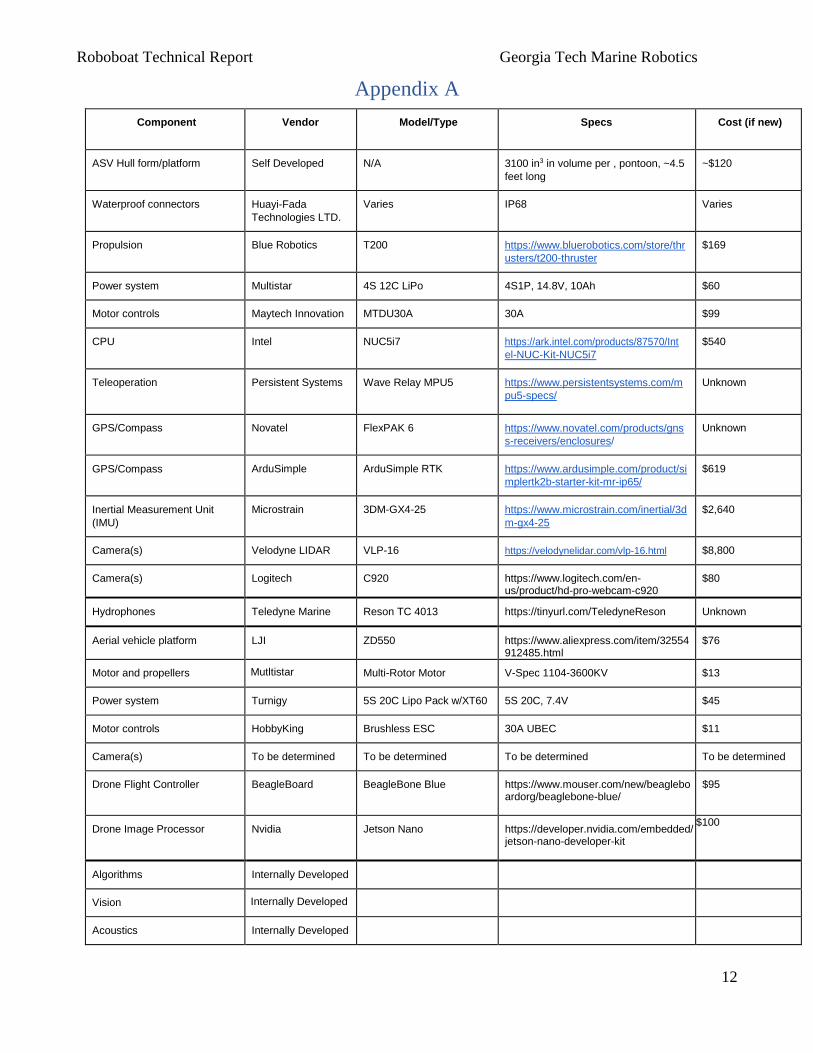
Appendix A
Component Vendor Model/Type Specs Cost (if new)
ASV Hull form/platform Self Developed N/A 3100 in3 in volume per , pontoon, ~4.5
feet long
~$120
Waterproof connectors Huayi-Fada
Technologies LTD.
Varies IP68 Varies
Propulsion Blue Robotics T200 https://www.bluerobotics.com/store/thr
usters/t200-thruster
$169
Power system Multistar 4S 12C LiPo 4S1P, 14.8V, 10Ah $60
Motor controls Maytech Innovation MTDU30A 30A $99
CPU Intel NUC5i7 https://ark.intel.com/products/87570/Int
el-NUC-Kit-NUC5i7
$540
Teleoperation Persistent Systems Wave Relay MPU5 https://www.persistentsystems.com/m
pu5-specs/
Unknown
GPS/Compass Novatel FlexPAK 6 https://www.novatel.com/products/gns
s-receivers/enclosures/
Unknown
GPS/Compass ArduSimple ArduSimple RTK https://www.ardusimple.com/product/si
mplertk2b-starter-kit-mr-ip65/
$619
Inertial Measurement Unit
(IMU)
Microstrain 3DM-GX4-25 https://www.microstrain.com/inertial/3d
m-gx4-25
$2,640
Camera(s) Velodyne LIDAR VLP-16 https://velodynelidar.com/vlp-16.html $8,800
Camera(s) Logitech C920 https://www.logitech.com/en-us/product/hd-pro-webcam-c920
$80
Hydrophones Teledyne Marine Reson TC 4013 https://tinyurl.com/TeledyneReson Unknown
Aerial vehicle platform LJI ZD550 https://www.aliexpress.com/item/32554912485.html
$76
Motor and propellers Mutltistar Multi-Rotor Motor V-Spec 1104-3600KV $13
Power system Turnigy 5S 20C Lipo Pack w/XT60 5S 20C, 7.4V $45
Motor controls HobbyKing Brushless ESC 30A UBEC $11
Camera(s) To be determined To be determined To be determined To be determined
Drone Flight Controller
BeagleBoard
BeagleBone Blue
https://www.mouser.com/new/beagleboardorg/beaglebone-blue/
$95
Drone Image Processor Nvidia
Jetson Nano
https://developer.nvidia.com/embedded/jetson-nano-developer-kit
$100
Algorithms Internally Developed
Vision Internally Developed
Acoustics Internally Developed
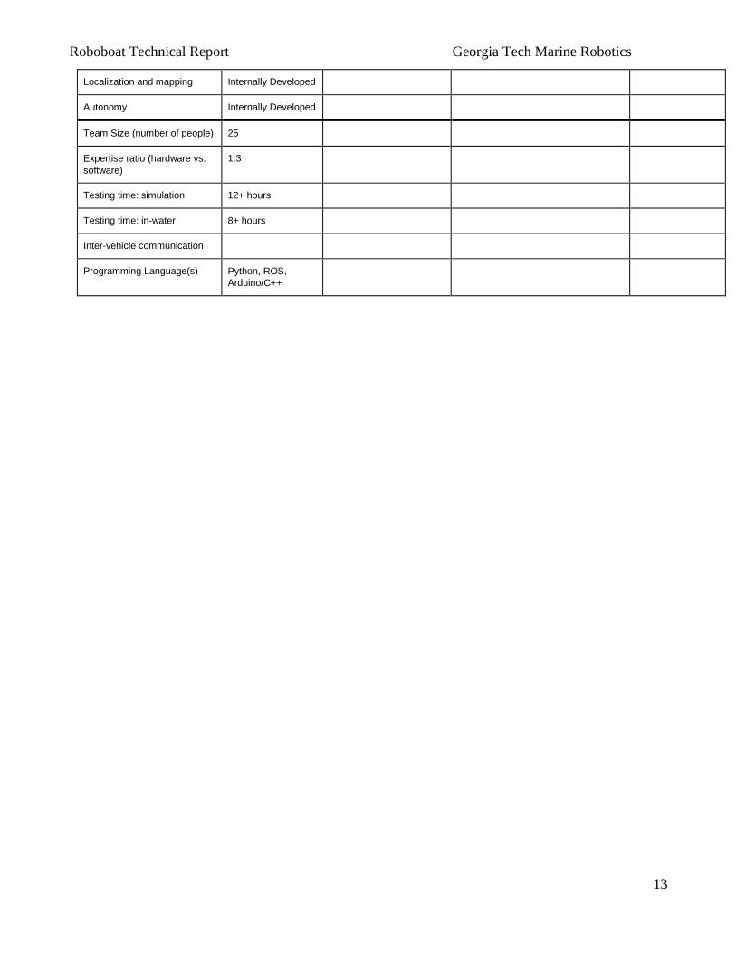
Roboboat Technical Report Georgia Tech Marine Robotics
13
Localization and mapping Internally Developed
Autonomy Internally Developed
Team Size (number of people) 25
Expertise ratio (hardware vs.
software)
1:3
Testing time: simulation 12+ hours
Testing time: in-water 8+ hours
Inter-vehicle communication
Programming Language(s) Python, ROS,
Arduino/C++