Embed Size (px)
Citation preview
Robot Arm Manipulation Using Depth-Sensing Cameras and Inverse Kinematics
Akhilesh Kumar Mishra Oscar Meruvia-Pastor Department of Computer Science Department of Computer Science
Memorial University of Newfoundland Memorial University of Newfoundland
Akm565-at-mun-dot-ca Oscar-at-mun-dot-ca
ABSTRACT: In this work we propose a new technique to manipulate a robotic arm which uses a depth camera to capture the user input and inverse kinematics to define the motion of the robotic arm. The presented technique is inexpensive to implement and easier to learn as compared to the current methods. Along with the easier manipulation of the robotic arm, the presented approach also adds some simple speech and gesture commands to control the end-effector which makes the interaction more intuitive.
KEYWORDS: inverse kinematics, gesture control, speech recognition, robot control, manipulation, interaction.
I. INTRODUCTION
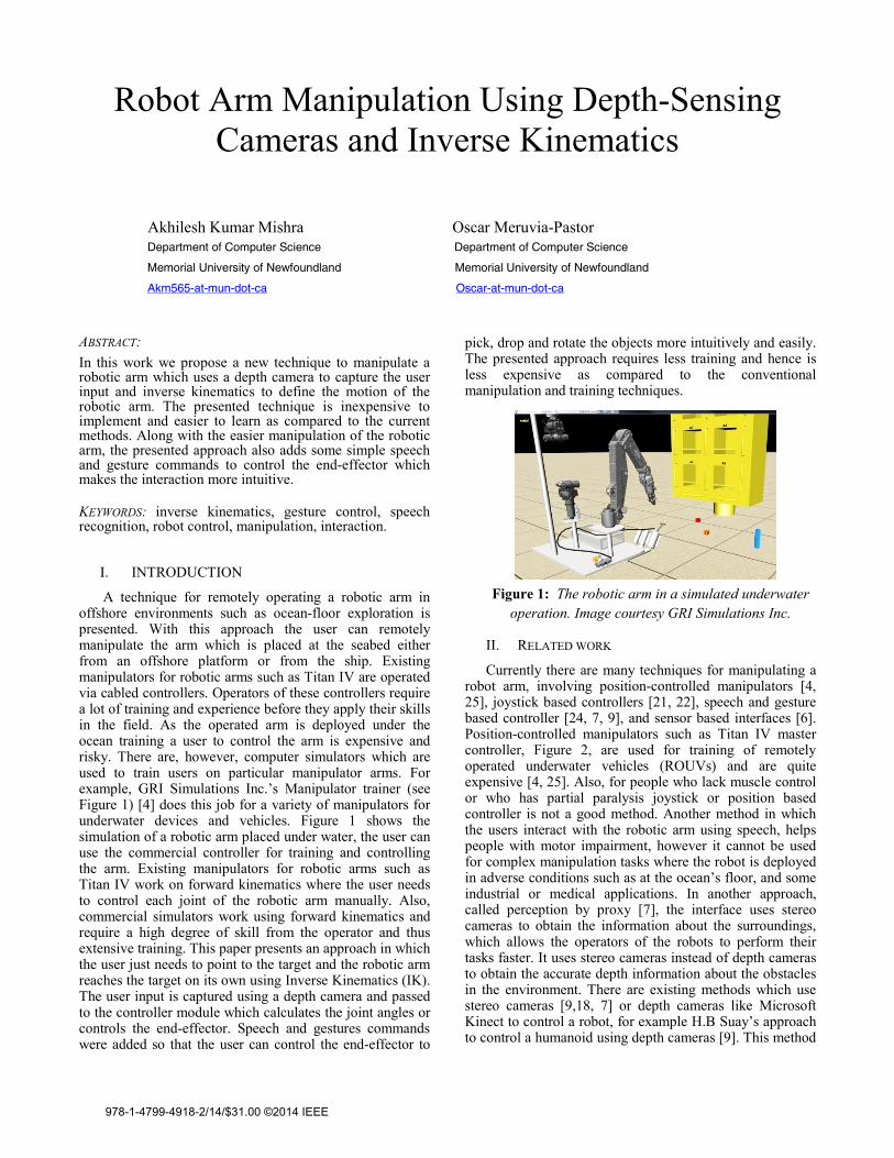
A technique for remotely operating a robotic arm in offshore environments such as ocean-floor exploration is presented. With this approach the user can remotely manipulate the arm which is placed at the seabed either from an offshore platform or from the ship. Existing manipulators for robotic arms such as Titan IV are operated via cabled controllers. Operators of these controllers require a lot of training and experience before they apply their skills in the field. As the operated arm is deployed under the ocean training a user to control the arm is expensive and risky. There are, however, computer simulators which are used to train users on particular manipulator arms. For example, GRI Simulations Inc.’s Manipulator trainer (see Figure 1) [4] does this job for a variety of manipulators for underwater devices and vehicles. Figure 1 shows the simulation of a robotic arm placed under water, the user can use the commercial controller for training and controlling the arm. Existing manipulators for robotic arms such as Titan IV work on forward kinematics where the user needs to control each joint of the robotic arm manually. Also, commercial simulators work using forward kinematics and require a high degree of skill from the operator and thus extensive training. This paper presents an approach in which the user just needs to point to the target and the robotic arm reaches the target on its own using Inverse Kinematics (IK). The user input is captured using a depth camera and passed to the controller module which calculates the joint angles or controls the end-effector. Speech and gestures commands were added so that the user can control the end-effector to
pick, drop and rotate the objects more intuitively and easily. The presented approach requires less training and hence is less expensive as compared to the conventional manipulation and training techniques.
II. RELATED WORK
Currently there are many techniques for manipulating a robot arm, involving position-controlled manipulators [4, 25], joystick based controllers [21, 22], speech and gesture based controller [24, 7, 9], and sensor based interfaces [6]. Position-controlled manipulators such as Titan IV master controller, Figure 2, are used for training of remotely operated underwater vehicles (ROUVs) and are quite expensive [4, 25]. Also, for people who lack muscle control or who has partial paralysis joystick or position based controller is not a good method. Another method in which the users interact with the robotic arm using speech, helps people with motor impairment, however it cannot be used for complex manipulation tasks where the robot is deployed in adverse conditions such as at the ocean’s floor, and some industrial or medical applications. In another approach, called perception by proxy [7], the interface uses stereo cameras to obtain the information about the surroundings, which allows the operators of the robots to perform their tasks faster. It uses stereo cameras instead of depth cameras to obtain the accurate depth information about the obstacles in the environment. There are existing methods which use stereo cameras [9,18, 7] or depth cameras like Microsoft Kinect to control a robot, for example H.B Suay’s approach to control a humanoid using depth cameras [9]. This method
Figure 1: The robotic arm in a simulated underwater operation. Image courtesy GRI Simulations Inc.
978-1-4799-4918-2/14/$31.00 ©2014 IEEE
uses depth images and skeletal tracking software to control the humanoid robot. This method is mostly suited for humanoids where the hand and leg gestures are mapped to the appropriate part of the humanoid; however for a robotic arm we need a different type of controller and intuitive interface. The work proposed here provides a more intuitive and easy interface to manipulate a robotic arm using an Intel’s depth sensing camera.
III SYSTEM OVERVIEW The block diagram of the overall system is shown in Figure 3. The user specifies the target position by moving his/her hands in front of a depth sensing camera. The depth camera returns the coordinates of the users’ hand and the coordinates are passed as target position to the inverse
kinematics module, where the joint angles for the arm simulator are calculated.After the joint angles have been calculated the robot arm simulator module applies the rotations calculated and the end-effector reaches the target. Once the target position has been reached the user can issue a voice or a gesture command to interact with the end-effector control module to pick and drop the objects.
IV HAND-DRIVEN COMMANDS USING DEPTH CAMERAS
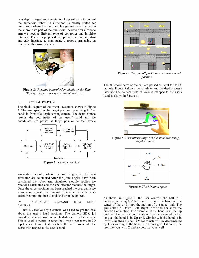
Intel’s Creative depth camera was used to get the data about the user‘s hand position. The camera SDK [5] provides the hand position and its distance from the camera. This is used to control a target ball which can move in 3D input space. Figure 4 shows how the ball moves into the scene with respect to the user’s hand.
The 3D coordinates of the ball are passed as input to the IK module. Figure 5 shows the simulator and the depth camera interface.The camera field of view is mapped to the users hand as shown in Figure 6.
As shown in Figure 6, the user controls the ball in 3 dimensions using his/ her hand. Placing the hand on the center of the grid stops the motion of the target ball. The grid cells Up, Down, Left, Right, Near and Far show the direction of motion. For example, if the hand is in the Up grid then the ball’s Y coordinate will be incremented by 1 as long as the hand is in Up grid. Similarly, if the hand is in Down grid then the ball’s Y coordinate will be decremented by 1 for as long as the hand is in Down grid. Likewise, the user interacts with X and Z coordinates as well.
Figure 2: Position-controlled manipulator for Titan IV [23], image courtesy GRI Simulations Inc.
Figure 3: System Overview
Figure 4: Target ball positions w.r.t user’s hand position
Figure 5: User interacting with the simulator using depth camera
Figure 6: The 3D input space
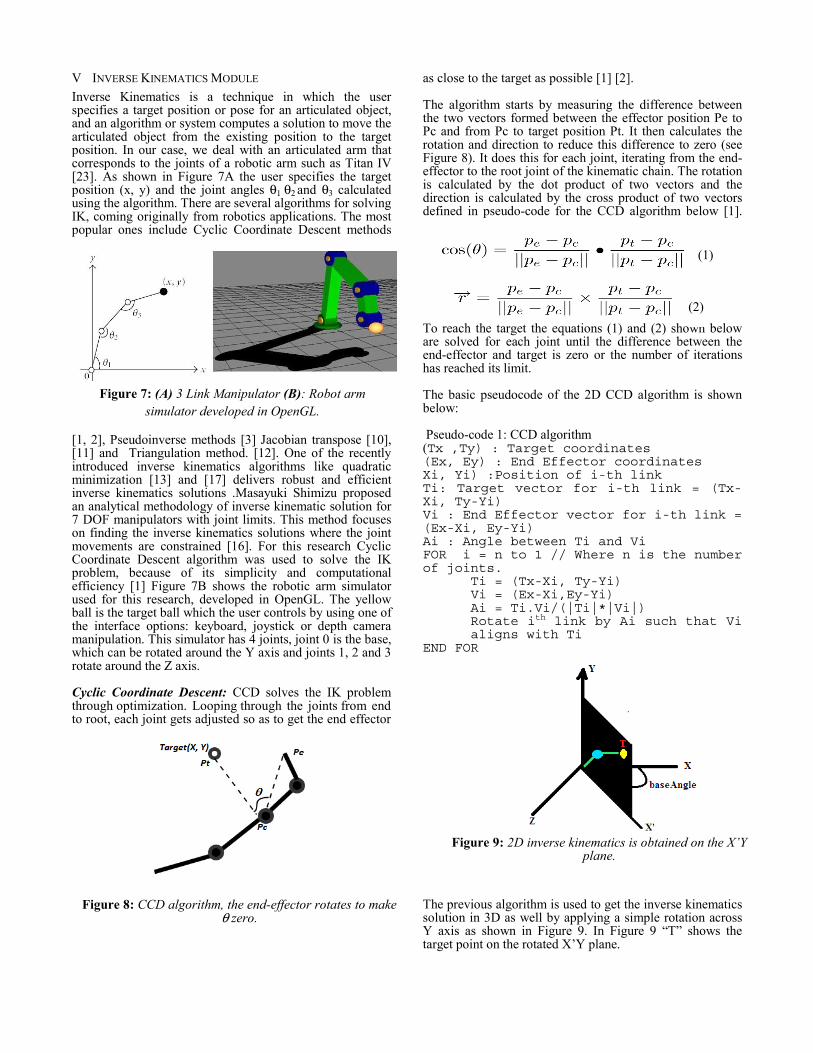
V INVERSE KINEMATICS MODULE Inverse Kinematics is a technique in which the user specifies a target position or pose for an articulated object, and an algorithm or system computes a solution to move the articulated object from the existing position to the target position. In our case, we deal with an articulated arm that corresponds to the joints of a robotic arm such as Titan IV [23]. As shown in Figure 7A the user specifies the target position (x, y) and the joint angles θ1 θ2 and θ3 calculated using the algorithm. There are several algorithms for solving IK, coming originally from robotics applications. The most popular ones include Cyclic Coordinate Descent methods
[1, 2], Pseudoinverse methods [3] Jacobian transpose [10], [11] and Triangulation method. [12]. One of the recently introduced inverse kinematics algorithms like quadratic minimization [13] and [17] delivers robust and efficient inverse kinematics solutions .Masayuki Shimizu proposed an analytical methodology of inverse kinematic solution for 7 DOF manipulators with joint limits. This method focuses on finding the inverse kinematics solutions where the joint movements are constrained [16]. For this research Cyclic Coordinate Descent algorithm was used to solve the IK problem, because of its simplicity and computational efficiency [1] Figure 7B shows the robotic arm simulator used for this research, developed in OpenGL. The yellow ball is the target ball which the user controls by using one of the interface options: keyboard, joystick or depth camera manipulation. This simulator has 4 joints, joint 0 is the base, which can be rotated around the Y axis and joints 1, 2 and 3 rotate around the Z axis. Cyclic Coordinate Descent: CCD solves the IK problem through optimization. Looping through the joints from end to root, each joint gets adjusted so as to get the end effector
as close to the target as possible [1] [2].
The algorithm starts by measuring the difference between the two vectors formed between the effector position Pe to Pc and from Pc to target position Pt. It then calculates the rotation and direction to reduce this difference to zero (see Figure 8). It does this for each joint, iterating from the end-effector to the root joint of the kinematic chain. The rotation is calculated by the dot product of two vectors and the direction is calculated by the cross product of two vectors defined in pseudo-code for the CCD algorithm below [1].
To reach the target the equations (1) and (2) shown below are solved for each joint until the difference between the end-effector and target is zero or the number of iterations has reached its limit.
The basic pseudocode of the 2D CCD algorithm is shown below:
Pseudo-code 1: CCD algorithm (Tx ,Ty) : Target coordinates (Ex, Ey) : End Effector coordinates Xi, Yi) :Position of i-th link Ti: Target vector for i-th link = (Tx-Xi, Ty-Yi) Vi : End Effector vector for i-th link = (Ex-Xi, Ey-Yi) Ai : Angle between Ti and Vi FOR i = n to 1 // Where n is the number of joints.
Ti = (Tx-Xi, Ty-Yi) Vi = (Ex-Xi,Ey-Yi) Ai = Ti.Vi/(|Ti|*|Vi|) Rotate ith link by Ai such that Vi aligns with Ti
END FOR
The previous algorithm is used to get the inverse kinematics solution in 3D as well by applying a simple rotation across Y axis as shown in Figure 9. In Figure 9 “T” shows the target point on the rotated X’Y plane.
(1)
(2)
Figure 7: (A) 3 Link Manipulator (B): Robot arm simulator developed in OpenGL.
Figure 9: 2D inverse kinematics is obtained on the X’Y plane.
Figure 8: CCD algorithm, the end-effector rotates to makeθ zero.
Pseudo-code 2: Rotation of the joint 0 at the base:
STEP 1: Get the 3D target coordinates of the target ball STEP 2: Calculate the baseAngle using arc tangent and apply the rotation to target point on X’Y plane. STEP 3: Find the solution using 2D inverse Kinematics algorithm on X’Y plane. STEP: Applying the rotation to all joints.
VI END-EFFECTOR CONTROL MODULE
The task that we are implementing with this IK system is a picking and dropping task, where objects are picked from the vicinity of the robot arm, and the user can drop them at different locations. This module uses the Intel SDK’s[5] speech processing and image processing APIs to let the user interact with the end-effector using speech commands like “Pick”, “Drop” for picking and dropping the objects from end-effector. The user can also use the “Thumbs up” or “Thumbs down” gestures for pick and drop commands. Once the joint angles have been calculated the user can interact with the End-effector and grab/ release the objects by speech, hand gesture, keyboard input or joystick command. This module also checks for any possible collisions of end-effector and obstacles. Following is a basic outline of the collision detection algorithm.
Algorithm for collision detection: (Ex, Ey): Position of End-effector (Ox,Oy) : Position of Obstacle Re: Radius of Sphere surrounding End-effector Ro: Radius of sphere surrounding obstacle d: Distance between obstacle and end-effector Calculate d; d = sqrt( (Ex-Ox)2+(Ey-Oy)2 ) IF d <= (Re + Ro) THEN Collision with Object ELSE No Collision END IF
VII INTERFACES The user is provided with 3 types of input methods to control the robotic arm. The first is the option to control the target ball using a standard keyboard and camera movement using mice. The second option is to control the robotic arm with an Extreme 3D Pro(tm) joystick in which the user selects a joint and rotates it (this approach is based on forward kinematics). The third option is where the user controls the target ball with his/her hand as described in section IV.
a) Keyboard interface + Inverse Kinematics: This enables the user to use the standard keyboard as an interacting device to perform manipulation of the target ball, while the IK module takes care of
moving the arm’s end effector towards the target ball.
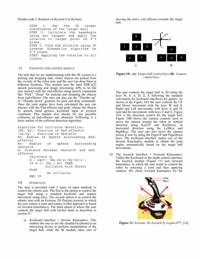
The user controls the target ball in 3D using the keys W, S, A, D, Z, X following the standard convention for keyboard interfaces for games. As shown in the Figure 10A the user controls the UP and Down movement with the keys W and S, Right and Left movements with keys A and D, near and far movements with keys Z and X. Figure 10A is the direction control for the target ball, Figure 10B shows the camera controls used to move the camera around the robot in vertical direction using KeyUP and KeyDown, in horizontal direction using the LeftKey and RightKey. The user can also move the camera across Z axis by using the PageUP and PageDown keys. The keyboard interface makes use of the Inverse Kinematics module to obtain the joint angles automatically based on the target ball movements.
b) The Joystick Interface + Forward Kinematics: Unlike the Keyboard or the depth camera interface the Joystick module (Figure 11) uses forward kinematics, in which the user needs to control the robot by selecting a joint and then applying rotation. We chose forward kinematics for the
Figure 10: (A): Target ball control keys (B): Camera control keys
Figure 11: Extreme 3D Joystick by Logitech™. [14]
joystick interface, because this is common practice when controlling most mechanical devices.
The direction X controls the rotation of the robot around its base around Y axis. The direction Y controls the rotation of the joints 1, 2 and 3. When the joystick is moved forward in Y direction the rotations are closing the robot arm and when the joystick is moved towards the back the rotations are opening the robotic arm. The user needs to select a joint using the additional numbered keys on the joystick (1 to 3) and then move the joystick across the Y direction to obtain the desired rotation. The user can also pick and drop objects using the numbered joystick button (4) as a toggle button.
c) The Depth camera interface + Inverse Kinematics: As shown in section IV the hand driven
commands are used to move the target ball in 3D as shown in Figure 6. Figure 12 shows the hand skeleton. The user moves the hand in up, down, right, left, near, far directions to control the target ball. The Inverse kinematics module calculates the angles based on the target position and applies it to the robot arm simulator, as previously explained in Sections IV and V.
VIII SYSTEM EVALUATION To validate the presented technique, experiments will be conducted where users will be asked to complete tasks using the three interfaces described above and have their performance compared. User experiments will be conducted in which each user will be asked to perform 2 tasks: A selection task and a picking and dropping task. Users will be expected to complete the tasks using all three interfaces.
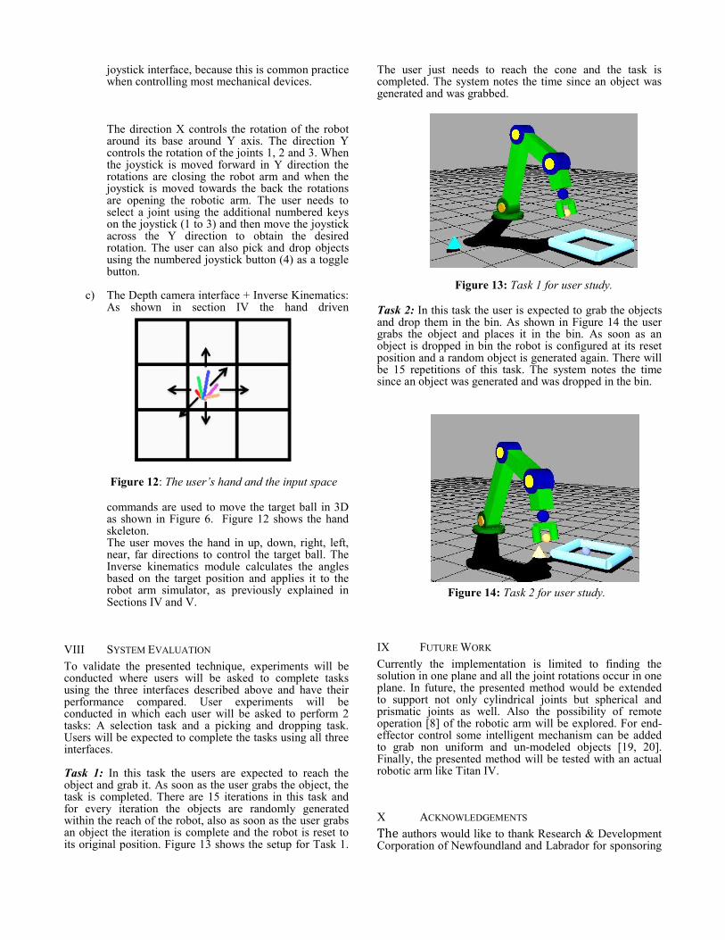
Task 1: In this task the users are expected to reach the object and grab it. As soon as the user grabs the object, the task is completed. There are 15 iterations in this task and for every iteration the objects are randomly generated within the reach of the robot, also as soon as the user grabs an object the iteration is complete and the robot is reset to its original position. Figure 13 shows the setup for Task 1.
The user just needs to reach the cone and the task is completed. The system notes the time since an object was generated and was grabbed.
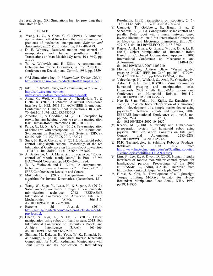
Task 2: In this task the user is expected to grab the objects and drop them in the bin. As shown in Figure 14 the user grabs the object and places it in the bin. As soon as an object is dropped in bin the robot is configured at its reset position and a random object is generated again. There will be 15 repetitions of this task. The system notes the time since an object was generated and was dropped in the bin.
IX FUTURE WORK Currently the implementation is limited to finding the solution in one plane and all the joint rotations occur in one plane. In future, the presented method would be extended to support not only cylindrical joints but spherical and prismatic joints as well. Also the possibility of remote operation [8] of the robotic arm will be explored. For end-effector control some intelligent mechanism can be added to grab non uniform and un-modeled objects [19, 20]. Finally, the presented method will be tested with an actual robotic arm like Titan IV.
X ACKNOWLEDGEMENTS The authors would like to thank Research & Development Corporation of Newfoundland and Labrador for sponsoring
Figure 13: Task 1 for user study.
Figure 12: The user’s hand and the input space
Figure 14: Task 2 for user study.
the research and GRI Simulations Inc. for providing their simulators in kind. XI REFERENCES [1] Wang, L. C., & Chen, C. C. (1991). A combined
optimization method for solving the inverse kinematics problems of mechanical manipulators. Robotics and Automation, IEEE Transactions on, 7(4), 489-499.
[2] D. E. Whitney, Resolved motion rate control of manipulators and human prostheses, IEEE Transactions on Man-Machine Systems, 10 (1969), pp. 47–53.
[3] W. A. Wolovich and H. Elliot, A computational technique for inverse kinematics, in Proc. 23rd IEEE Conference on Decision and Control, 1984, pp. 1359–1363.
[4] GRI Simulations Inc.. In Manipulator Trainer (2014). http://www.grisim.com/products.html#ManipTrainer
[5] Intel. In Intel® Perceptual Computing SDK (2013). http://software.intel.com/en-us/vcsource/tools/perceptual-computing-sdk
[6] Assad, C., Wolf, M., Stoica, A., Theodoridis, T., & Glette, K. (2013). BioSleeve: A natural EMG-based interface for HRI. 2013 8th ACM/IEEE International Conference on Human-Robot Interaction (HRI), 69–70. doi:10.1109/HRI.2013.6483505
[7] Atherton, J., & Goodrich, M. (2011). Perception by proxy: humans helping robots to see in a manipulation task. Human-Robot Interaction (HRI), 109–110.
[8] Parga, C., Li, X., & Yu, W. (2013). Tele-manipulation of robot arm with smartphone. 2013 6th International Symposium on Resilient Control Systems (ISRCS), 60–65. doi:10.1109/ISRCS.2013.6623751
[9] Suay, H. B., & Chernova, S. (2011). Humanoid robot control using depth camera. Proceedings of the 6th International Conference on Human-Robot Interaction - HRI ’11, 401. doi:10.1145/1957656.1957802
[10] A. Balestrino, G. D. Maria, and L. Sciavicco, “Robust control of robotic manipulators,” in Proc. of 9th IFACWorld Congress, pp. 2435– 2440, 1984.
[11] W. A. Wolovich and H. Elliot, “A computational technique for inverse kinematics,” in Proc. of 23rd IEEE Conference on Decision and Control,
[12] Mukundan, R. (2007). Triangulation�: A new algorithm for Inverse Kinematics, (December), 181–186.
[13] Wang, W., Suga, Y., Iwata, H., & Sugano, S. (2012). Solve inverse kinematics through a new quadratic minimization technique. 2012 IEEE/ASME International Conference on Advanced Intelligent Mechatronics (AIM), 306–313. doi:10.1109/AIM.2012.6266007
[14] Extreme 3d Joystick (2014), http://gaming.logitech.com/en-ca/product/extreme-3d-pro-joystick
[15] Cheon, S., Ryu, K., & Oh, Y. (2013). Object manipulation using robot arm-hand system. 2013 10th International Conference on Ubiquitous Robots and Ambient Intelligence (URAI), 163–166. doi:10.1109/URAI.2013.6677503
[16] Shimizu, M., Kakuya, H., Yoon, W.-K., Kitagaki, K., & Kosuge, K. (2008). Analytical Inverse Kinematic Computation for 7-DOF Redundant Manipulators with Joint Limits and Its Application to Redundancy
Resolution. IEEE Transactions on Robotics, 24(5), 1131–1142. doi:10.1109/TRO.2008.2003266
[17] Uzunovic, T., Golubovic, E., Baran, E. a., & Sabanovic, A. (2013). Configuration space control of a parallel Delta robot with a neural network based inverse kinematics. 2013 8th International Conference on Electrical and Electronics Engineering (ELECO), 497–501. doi:10.1109/ELECO.2013.6713892
[18] Rajpar, A. H., Huang, Q., Zhang, W., Jia, D., & Li, K. (2007). Object Manipulation of Humanoid Robot Based on Combined Optimization Approach. 2007 International Conference on Mechatronics and Automation, 1148–1153. doi:10.1109/ICMA.2007.4303710
[19] Michael Taylor, Andrew Blake “Visual guided grasping in 3D” IEEE Int Conf: pp 1050- 4729/94, 2004.” IEEE Int Conf: pp 1050- 4729/94, 2004.
[20] Vahrenkamp, N., Wieland, S., Azad, P., Gonzalez, D., Asfour, T., & Dillmann, R. (2008). Visual servoing for humanoid grasping and manipulation tasks. Humanoids 2008 - 8th IEEE-RAS International Conference on Humanoid Robots, 406–412. doi:10.1109/ICHR.2008.4755985
[21] Neo Ee Sian; Yokoi, K.; Kajita, S.; Kanehiro, F.; Tanie, K., "Whole body teleoperation of a humanoid robot - development of a simple master device using joysticks," Intelligent Robots and Systems, 2002. IEEE/RSJ International Conference on , vol.3, no., pp.2569,2574 vol.3, 2002 doi: 10.1109/IRDS.2002.1041657
[22] Keerio, M. (2008). A friendly and human-based teleoperation system for humanoid robot using joystick. 2008 7th World Congress on Intelligent Control and Automation, 2283–2288. doi:10.1109/WCICA.2008.4593278
[23] FMC Technologies, in Schilling Robotics Products, Retrieved on 10th July from http://www.fmctechnologies.com/en/SchillingRobotics/Technologies/Schilling-TITAN-4.aspx
[24] Lim, S., Lee, K., & Kwon, D. (2003). Human friendly interfaces of robotic manipulator control system for handicapped persons. Proceedings of the 2003 IEEE/ASME …, (Aim), 435–440. Retrieved from http://robot.kaist.ac.kr/paper/article.php?n=53
[25] Hirose, S., Chu, R. “Development of a Lightweight Torque Limiting M-Drive Actuator for Hyper-Redundant Manipulator Float Arm”, ICRA 1999, pp.2831-2836