Embed Size (px)
Citation preview

25
Advances in Production Engineering & Management ISSN 1854-6250
Volume 8 | Number 1 | March 2013 | pp 25–32 Journal home: apem-journal.org
http://dx.doi.org/10.14743/apem2013.1.150
APEM journal
Robot laser hardening and the problem
of overlapping laser beam
Babic, M.a,*
, Balic, J.b, Milfelner, M.
c, Belic, I.
d, Kokol, P.
e, Zorman, M.
f, Panjan, P.
g
aEMO orodjarna d.o.o., Bezigrajska 10, 3000 Celje, Slovenia, EU
bFaculty of Mechanical Engineering, University of Maribor, Smetanova 17, 2000 Maribor, Slovenia, EU
cTic-lens d.o.o., Bezigrajska 10, 3000 Celje, Slovenia, EU
dInstitute of Materials and Technology, Slovenia, EU
eFaculty of Health Sciences, University of Maribor, Zitna 15, 2000 Maribor, Slovenia, EU
fFaculty of Electrical Engineering and Computer Science, University of Maribor, Smetanova 17, 2000 Maribor, Slovenia, EU
gJozef Stefan Institute, Jamova 39, 1000 Ljubljana, Slovenia, EU
A B S T R A C T A R T I C L E I N F O
Since 1970, many studies of various laser machining processes and their appli-
cations have been published. This paper describes some of our experience in
laser surface remelting, consolidating, and hardening of steels. We focus on the
problem of robot laser hardening of metals with overlapping of the hardened
zone. The process of laser hardening with remelting of the surface layer allows
us to very accurately determine the depth of modified layers. In this proce-
dure, we know the exact energy input into the material. Heating above the
melting temperature and then rapidly cooling causes microstructural changes
in materials, which affect the increase in hardness. We identify the relationship
between hardness and width of overlapping. We describe the results of previ-
ous work, research, and experience in robot laser hardening of metals. We also
show the results of laser processing techniques with the problem of overlap-
ping. Our tests were carried out on materials of DIN standard 1.2379 and
1.7225, and measurements were performed in the hardened zone of overlap-
ping at 2 mm, 3 mm, 4 mm, 6 mm, and 10 mm. We show relationship between
hardness and width of overlap for material of DIN standard 1.2379 and
1.7225. The modeling of the relationship was obtained by the 3 layers artificial
neural network.
© 2013 PEI, University of Maribor. All rights reserved.
Keywords:
Robot
Laser
Hardening
Overlapping
Neural network
*Corresponding author:
(Babic, M.)
1. Introduction
Different tool steels are widely used in industrial applications based on good performance, a
wide range of mechanical properties, machinability, wear resistance, and cheapness [1-6]. By
laser remelting the surface of the materials, we can significantly improve their wear properties
better like inductive hardening. Robot laser surface [7, 8] remelting is one of the most promising
techniques for surface modification of the microstructure of a material to improve wear and
corrosion resistance. Laser hardening [9] is a metal surface treatment process complementary
to conventional flame and induction hardening processes. A high-power laser beam is used to
rapidly and selectively heat a metal surface to produce hardened case depths of up to 1.5 mm
with a hardness value of up to 65 HRc. The high hardness of the martensitic microstructure pro-
vides improved properties such as wear resistance and strength. Advantages of laser hardening
over inductive hardening are:

Babic, Balic, Milfelner, Belic, Kokol, Zorman, Panjan
26
• laser is a source of energy with outstanding characteristics (contactless methods, co
trolled input of energy, high capacity, constant process, precise positioning),
• lower costs for additional machining,
• no use of cooling agents or chemicals,
• high flexibility,
• the process can be automated and integrated in the production process,
• superior wear resistance of hardened surface,
• selective hardening of complex geometrical shapes,
• local hardening,
• no local melting of material,
• minimal deformation,
• high accuracy,
• low heat input and thus low distortion,
• consistently high product quality due to process control.
For laser heat treatment, a CO
formations take place in the heat
microstructure is formed by heating
or nodules. Non-uniform austenite
we see a robot laser cell for hardening
by the overlapping of laser beam.
ing artificial neural networks for the prediction
heat treatment and to judge their perspective use in this field. The achieved models enable the
prediction of final mechanical material properties on the basis of decisive parameter width of
overlap of laser beam influencing these propert
2. Material preparation and experimental method
2.1 Material preparation
Robot laser cell can be used to provide the heat necessary for the treatment process.
robot laser cell RV60–40 from Company Reis
speeds and large work envelopes the RV
path-related tasks. Laser beam have rectangle shape. We use 5×23
that with this optic we hardened approximate 23
with wavelength 700–1000 nm. Maximum pow
specimens with 1500 W output power. Robot
[10]. In previous work [11] we research how parameter of angel impact on hardness of material
of DIN standard 1.7225. In this
Balic, Milfelner, Belic, Kokol, Zorman, Panjan
Advances in Production Engineering & Management 8(1) 2013
laser is a source of energy with outstanding characteristics (contactless methods, co
trolled input of energy, high capacity, constant process, precise positioning),
lower costs for additional machining,
no use of cooling agents or chemicals,
the process can be automated and integrated in the production process,
superior wear resistance of hardened surface,
selective hardening of complex geometrical shapes,
no local melting of material,
low heat input and thus low distortion,
consistently high product quality due to process control.
CO2 laser with high power continuous mode is used.
heat-hardened zone only in the solid state. A fixed
heating austenite with a concentration gradient
austenite is transformed by cooling to martensite and
hardening. This paper describes the robot laser hardening
by the overlapping of laser beam. The aim of the contribution is to outline possibilities of appl
ing artificial neural networks for the prediction of mechanical steel properties
heat treatment and to judge their perspective use in this field. The achieved models enable the
prediction of final mechanical material properties on the basis of decisive parameter width of
overlap of laser beam influencing these properties.
Fig. 1 Robot laser hardened cell
Material preparation and experimental method
Robot laser cell can be used to provide the heat necessary for the treatment process.
40 from Company Reis Robotics. As 6-axes universal robots with high path
speeds and large work envelopes the RV-robots are especially suited for the high demands of
related tasks. Laser beam have rectangle shape. We use 5×23 mm optics, F200. It means,
we hardened approximate 23 mm width. Robot laser works continuously
nm. Maximum power of robot laser cell is 3000
W output power. Robot laser hardening presents a variety of
] we research how parameter of angel impact on hardness of material
work, we were interested on problem of overlapping. We use
Advances in Production Engineering & Management 8(1) 2013
laser is a source of energy with outstanding characteristics (contactless methods, con-
trolled input of energy, high capacity, constant process, precise positioning),
the process can be automated and integrated in the production process,
mode is used. Phase trans-
fixed pearlite-ferrite
gradient of graphite flakes
and ferrite. In Fig. 1,
hardening of metals
The aim of the contribution is to outline possibilities of apply-
of mechanical steel properties after robot laser
heat treatment and to judge their perspective use in this field. The achieved models enable the
prediction of final mechanical material properties on the basis of decisive parameter width of
Robot laser cell can be used to provide the heat necessary for the treatment process. We use
axes universal robots with high path
robots are especially suited for the high demands of
mm optics, F200. It means,
mm width. Robot laser works continuously
er of robot laser cell is 3000 W. We hardened
variety of problems
] we research how parameter of angel impact on hardness of material
were interested on problem of overlapping. We use ma-

Robot laser hardening and the problem of overlapping laser beam
Advances in Production Engineering & Management 8(1) 2013 27
Fig. 2 Hardening of material
Fig. 3 Hardening material next to hardened zone
Fig. 4 Hardening material with overlapping
terial of DIN standard 1.2379 and 1.7225. Chemical composition of the material of DIN standard
1.7225 contained 0.38–0.45 % C, max 0.4 % Si, 0.6–0.9 % Mn, max 0.025 % P, max 0.035 % S and
0.15–0.3 % Mo. Chemical composition of the material of DIN standard 1.2379 contained 1.53 %
C, 0.35 % Si, 0.4 % Mn, 12 % Cr and 0.85 % V. First, we hardened the materials (Fig. 2) with
speed 2 mm/s and with temperature 1100 °C. Also, robot was moved linear. We use optimal
parameters of robot laser cell of speed and temperature [12], which give us the best results of
hardness. Very important is that robot laser cell has constant speed travel of laser beam. After
this process, we hardened them again over the hardened zone, where we use different width of
overlapping.
Firstly, we hardened material next to the hardened zone (Fig. 3), and then we hardened ma-
terial over the hardened zone (Fig. 4) with different widths: 2 mm, 3 mm, 4 mm, 6 mm, and 10
mm. Our objective was to find a relationship between hardness and width of overlapping (Fig. 3
and Fig. 4). Material of DIN standard 1.2379 have hardness of 7 HRc and material of DIN stan-
dard 1.7225 6.5 HRc.
2.2 Experimental method
For analysis of the results, we used an intelligent system method, namely a neural network. Neu-
ral networks are model-less approximators, capable of performing the approximation–
modelling operations regardless of any relational knowledge of the nature of the modelled prob-
lem. The relational knowledge is typically represented by the set of equations describing the
observed variables and constants used to describe the system’s dependencies. The common use

Babic, Balic, Milfelner, Belic, Kokol, Zorman, Panjan
28 Advances in Production Engineering & Management 8(1) 2013
Fig. 5 The symbolic representation of the artificial neural network cell
of neural networks is the multi-dimensional function modelling [13], i. e., re-creation of the sys-
tem’s behaviour on the basis of the set of known discrete points representing the various states
of the system. We are using the feed-forward neural networks with supervised training algo-
rithms. The basic building element of used neural network is an artificial neural network cell
(Fig. 5). Each artificial neural network consists of a number of inputs (synapses) that are connected to
the summing junction. The values of inputs are multiplied by adequate weights w and summed
with other weighted input values. The training process changes the values of the weights. The
sum of weighted inputs is an argument of the so called activation function which produces the
final output of an artificial neural cell. In most cases, the activation function is of sigmoidal type.
Artificial neural network cells are combined in the neural network architecture which is com-
posed at least of two layers that provide communication with outer world. Those layers are re-
ferred to as the input and output layer. Between the two, there are hidden layers which trans-
form the signal from the input layer to the output layer. They contribute significantly to the non-
linearity of the neural network input-output transfer function. The process of adaptation of a
neural network weights is called training. During the supervised training, the input-output pairs
are presented to the neural network meaning in which each presented input value the desired
output value (target value) is also known for they are both part of the training set. The training
algorithm iteratively changes the weights of the neural network in order to get closer to the de-
sired output values. Data points are consecutively presented to the neural network. For each
data point, the neural network produces an output value which normally differs from the target
value. The difference between the two is the approximation error in the particular data point.
The error is then propagated back through the neural network towards the input, and the cor-
rection of the weights is made in the direction to lower the output error. There are numerous
methods for correction of the weights. The most frequently used algorithm is called the error
back propagation algorithm. When the training achieves the desired accuracy, it is stopped.
From here on, the model can reproduce the given data points with a prescribed precision for all
data points.
3. Results and discussion
3.1 Material 1.2379
Table 1 summarises the results of measurements of hardness in the overlapping zone. All meas-
urements were carried out from the left to right side of the zone. The data for laser beam overlap
of 2 mm, 3 mm, 4 mm, 6 mm, and 10 mm are presented in Tables 2, 3, 4, 5, and 6 respectively.
Below each table is an image showing the laser beam overlapping of hardened material.
Table 1 Hardness of laser-hardened material with overlap of 0 mm
Overlap (mm)
Hardness (HRc) Direction
0 59, 59, 57, 55, 54, 50, 42, 15 right side of the zone of overlapping
0 58, 58, 55, 54, 53, 51, 44, 15 left side of the zone of overlapping

Advances in Production Engineering & Management
Fig
Table 2 Hardness of laser
Overlap (mm)
2 58, 55, 50, 45, 31, 12
2 57, 56, 54, 51, 46, 36
Fig.
Table 3
Overlap (mm)
3
3
Fig. 8
Table 4 Hardness of laser
Overlap (mm)
4 55, 52, 50, 47, 40, 30
4
Fig. 9
Table 5 Hardness of laser
Overlap (mm) 6
6
Fig.
Robot laser hardening and the problem of overlapping laser beam
Advances in Production Engineering & Management 8(1) 2013
Fig. 6 Hardened zone with overlap of 0 mm
Hardness of laser-hardened material with overlap of 2 mm
Hardness (HRc) Direction
58, 55, 50, 45, 31, 12 right side of the zone of overlapping
57, 56, 54, 51, 46, 36 left side of the zone of overlapping
Fig. 7 Hardened zone with overlap of 2 mm
Hardness of laser-hardened material with overlap of 3 mm
Hardness (HRc) Direction
56, 54, 52, 50, 43 right side of the zone of overlapping
52, 48, 36, 18, 14 left side of the zone of overlapping
Fig. 8 Hardened zone with overlap of 3 mm
Hardness of laser-hardened material with overlap of 4 mm
Hardness (HRc) Direction
55, 52, 50, 47, 40, 30 right side of the zone of overlapping
57, 54, 47, 41, 29 left side of the zone of overlapping
Fig. 9 Hardened zone with overlap of 4 mm
Hardness of laser-hardened material with overlap of 6 mm
Hardness (HRc) Direction
57, 53, 48, 42, 39 right side of the zone of overlapping
56, 54, 48, 43 left side of the zone of overlapping
Fig. 10 Hardened zone with overlap of 6 mm
Robot laser hardening and the problem of overlapping laser beam
29
Direction
right side of the zone of overlapping
left side of the zone of overlapping
hardened material with overlap of 3 mm
Direction
right side of the zone of overlapping
left side of the zone of overlapping
Direction
right side of the zone of overlapping
left side of the zone of overlapping
Direction
right side of the zone of overlapping
left side of the zone of overlapping

Babic, Balic, Milfelner, Belic, Kokol, Zorman, Panjan
30
Table 6 Hardness of laser
Overlap (mm)
10 55, 52, 53, 59, 60, 60, 59
10 61, 61, 62, 62, 62, 61, 59
Fig. 11
Fig. 12 shows the relationship between hardness and width of overlap
standard 1.2379. The modeling of the relationship was obtained by the three layer neural ne
work. We considered only the highest measured
hardness occurs at the maximum
3.2 Material 1.7225
We carried out tests on the material of DIN standard
out overlapping. Second, we used equal process, but we harde
of overlapping. Measurements
ments, from left to right, are of hardness
ing with overlapping. Measurements
hardened zone. Table 8 shows the hardness values for
the overlap zone is 0, 1, 2, 3, 4,
Table 7 shows the hardness values for
Hardness (HRc)
7, 10, 49, 57,57
From the data in the tables
different zones of overlap. For
ening temperature was 1100 °C.
terials of DIN standard 1.2379
zones touch, we have hardness
between 2 HRc, 3 HRc, 4 HRc, and
58 HRc. Surprisingly, we find the best results in the
measured at 59 HRc (Table 6).
Fig. 12 Relationship between hardness and overlap
relationship was obtained by the three layer neural network.
Balic, Milfelner, Belic, Kokol, Zorman, Panjan
Advances in Production Engineering & Management 8(1) 2013
Hardness of laser-hardened material with overlap of 10 mm
Hardness (HRc) Direction
55, 52, 53, 59, 60, 60, 59 right side of the zone of overlapping
61, 61, 62, 62, 62, 61, 59 left side of the zone of overlapping
Fig. 11 Hardened zone with overlap of 10 mm
relationship between hardness and width of overlap for a material of DIN
. The modeling of the relationship was obtained by the three layer neural ne
the highest measured hardness. The results show
at the maximum width of the laser beam overlap.
on the material of DIN standard 1.7225. Firstly, we hardened material wit
out overlapping. Second, we used equal process, but we hardened material with
of overlapping. Measurements from the overlapping zones are presented in Table
of hardness after hardening without overlapping and
Measurements were carried out from the soft zone towards the centre of
shows the hardness values for material of DIN standard
, 6, 8, and 10 mm, measured from left to right.
shows the hardness values for material of DIN standard 1.7225 without overlapping.
Table 7 Hardness without overlapping
Direction
From the soft zone towards the centre of the hardened
zone
in the tables we can determine the optimal hardness of hardened material
each sample, we used 5 × 23 mm optics, F200.
°C. Speed of laser hardening was 2 mm/s. Comparing
standard 1.2379 and 1.7225, we can see they are quite similar.
hardness between 15 HRc and 59 HRc. Hardness in the
and 6 HRc yields similar results; hardness is between
Surprisingly, we find the best results in the overlapping zone 10 mm, wher
.
Relationship between hardness and overlap width for material of DIN 1.2379 standard. The modeling of the
relationship was obtained by the three layer neural network.
Advances in Production Engineering & Management 8(1) 2013
Direction
right side of the zone of overlapping
the zone of overlapping
for a material of DIN
. The modeling of the relationship was obtained by the three layer neural net-
The results show that the highest
. Firstly, we hardened material with-
ned material with different width
zones are presented in Table 8. Measure-
without overlapping and after harden-
towards the centre of
standard 1.7225, when
without overlapping.
From the soft zone towards the centre of the hardened
hardened material in
F200. Robot laser hard-
Comparing data for ma-
similar. When hardened
in the overlapping zone
is between 30 HRc and
mm, where hardness is
standard. The modeling of the
Advances in Production Engineering & Management
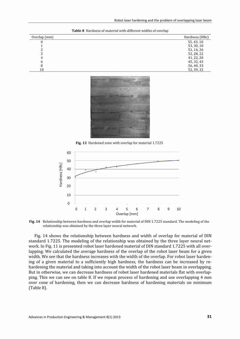
Table 8 Hardness of material with different widths of overlap
Overlap (mm)
0 1 2 3 4 6 8
10
Fig. 13
Fig. 14 shows the relationship between hardness
standard 1.7225. The modeling of the relationship was obtained by the three layer neural
work. In Fig. 11 is presented robot laser hardened material of
lapping. We calculated the average
width. We see that the hardness
ing of a given material to a sufficiently
hardening the material and taking into account
But in otherwise, we can decrea
ping. This we can see on table 8. If we repeat process of hardening and use overlapping 4
over cone of hardening, then we can
(Table 8).
Fig. 14 Relationship between hardness and overlap width for material of DIN 1.7225 standard. The
relationship was obtained by the three layer neural network.
Robot laser hardening and the problem of overlapping laser beam
Advances in Production Engineering & Management 8(1) 2013
Hardness of material with different widths of overlap
Hardened zone with overlap for material 1.7225
shows the relationship between hardness and width of overlap for material of
. The modeling of the relationship was obtained by the three layer neural
ig. 11 is presented robot laser hardened material of DIN standard 1.7225 with all ove
the average hardness of the overlap of the robot laser beam
hardness increases with the width of the overlap. For robot
sufficiently high hardness, the hardness can be increased by
taking into account the width of the robot laser beam
therwise, we can decrease hardness of robot laser hardened materials flat
ping. This we can see on table 8. If we repeat process of hardening and use overlapping 4
hardening, then we can decrease hardness of hardening materials on minimum
Relationship between hardness and overlap width for material of DIN 1.7225 standard. The
relationship was obtained by the three layer neural network.
Robot laser hardening and the problem of overlapping laser beam
31
Hardness (HRc)
55, 43, 10 53, 30, 10 51, 14, 26 52, 28, 22 41, 22, 20 45, 32, 43 56, 40, 33 52, 39, 32
width of overlap for material of DIN
. The modeling of the relationship was obtained by the three layer neural net-
1.7225 with all over-
the robot laser beam for a given
For robot laser harden-
be increased by re-
the robot laser beam in overlapping.
se hardness of robot laser hardened materials flat with overlap-
ping. This we can see on table 8. If we repeat process of hardening and use overlapping 4 mm
decrease hardness of hardening materials on minimum
Relationship between hardness and overlap width for material of DIN 1.7225 standard. The modeling of the

Babic, Balic, Milfelner, Belic, Kokol, Zorman, Panjan
32 Advances in Production Engineering & Management 8(1) 2013
4. Conclusion
In robot laser surface hardening of material of DIN standard 1.7225 and 1.2379, we achieved
an impressive increase in the hardness of the surface layers melted, which significantly in-
creases the wear resistance of such modified products. Experimental results have confirmed that
material of DIN standard 1.7225 and 1.2379 is very favourable for laser heat treatment, since
the durability and wear characteristics of the material were significantly improved after thermal
laser treatment. We compared the hardness of two different materials of DIN standard 1.7225
and 1.2379 and found the optimum hardness of each hardened material. Robot laser hardening
is very useful in industrial applications. In this paper, we have considered the problem of robot
laser hardening in terms of the impact of the width of overlap of the laser beam zone on the
hardness of the material. We use method of intelligent system, neural network for analyze ex-
perimental data. Robot laser hardening is used on mechanical components, such astorsion
springs, gears, tools, dies, and in cutting-edge applications in the engineering, military, aero-
space, and aviation industries. Also our very important investigate is that we can achieved de-
creasing and increasing hardness of materials with overlapping (we repeat process of harden-
ing).
In the future, we hope to explore the problem of overlapping in hardened specimens as a
function of several parameters for laser hardening in a robot cell. These laser parameters are
power, energy density, focus distance, energy density in the focus, focal position, temperature,
and speed of germination. Robot laser hardening presents many problems. In these problems,
we can vary all of the above mentioned parameters (which give us a large number of combina-
tions). Similarly, we are interested in the opposite problem, i. e., how to reduce the hardness of
the hardened material.
Acknowledgements
The present work was supported by the European Social Fund of the European Union.
References
[1] Totten, G. E. (2006). PhD. Fasm, Steel heat treatment, second edition.
[2] Xu, Z., Leong, K. H., Reed, C. B. (2008). Nondestructive evaluation and real-time monitoring of laser surface hard-
ening, Journal of Materials Processing Technology, Vol. 206, No. 1-3, 120-125.
[3] Kennedy, E., Byrne, G., Collins, D. N. (2004). A review of the use of high power diode lasers in surface hardening,
Journal of Materials Processing Technology, Vol. 155-156, 1855-1860.
[4] Ion, J. C. (2005). Laser processing of Engineering Material-Principles, procedures and industrial applications,
Elsevier, 2005.
[5] Ganeev, R. A. (2002). Low power laser hardening of steels, Journal of Materials Processing Technology, Vol. 121,
No. 2-3, 414-419.
[6] Pashby, I. R., Barnes, S., Bryden, B. G. (2003). Surface hardening of steel using a high power diode laser, Journal of
Materials Processing Technology, Vol. 139, No. 1-3, 585-588.
[7] Patil, S. B. (2007). Surface treatment using laser heat source, PhD Thesis, Swami Ramanand Teerth Marathwada
University, Vishnupuri, Nanded.
[8] Kramar, D. (2009). High-pressure cooling assistance in machining of hard-to-machine materials, PhD Thesis,
Faculty of Mechanical Engineering, Ljubljana, Slovenia.
[9] Babic, M., Stepišnik, S., Milfelner, M., Babič, S. (2011). Point robot laser hardening. In: Perme, T., Svetak, D. (ed.),
Industrijski forum IRT, Portoroz, junij 2011. Vir znanja in izkušenj za stroko: zbornik foruma. Skofljica, 31-34.
[10] Babic, M. Robot laser hardening with different angels on different materials. In: Godec, M. (ed.), (2011). 19th
Conference on Materials and Technology, Portoroz, Slovenia. Program and book of abstracts. Institute of materi-
als and technology, Ljubljana.
[11] Babic, M. (2010). Optimal parameters of robot laser cell for hardening with different angles. In: Zajc, B. (ed.),
Trost, A. (ed.). Proceeding of the Nineteen International Electrotechnical and Computer Conference ERK 2010,
Portoroz, Slovenia, (Proceedings Electrotehnical and Computer conference ERK). IEEE Region 8, Slovenian sec-
tion IEEE, 219-222.
[12] Tikk, D., Kóczy, L. T., Gedeon, T. D. (2003). A survey on universal approximation and its limits in soft computing
techniques, International Journal of Approximate Reasoning. Vol. 33, No. 2, 185-202.
[13] ElHefnawi, M., Mysara, M. (2012). Recurrent Neural Networks and Soft Computing, Intech, Rijeka.