Embed Size (px)
Citation preview
ENVIRONMENTALSYSTEM
C
ER T I F I ED
MA
NAGEMENT SYST
EM
JQA-EM0924JQA-0813
QUALITY SYSTEM
C
ER T I F I ED
MA
NAGEMENT SYST
EM
R009QMS Accreditation
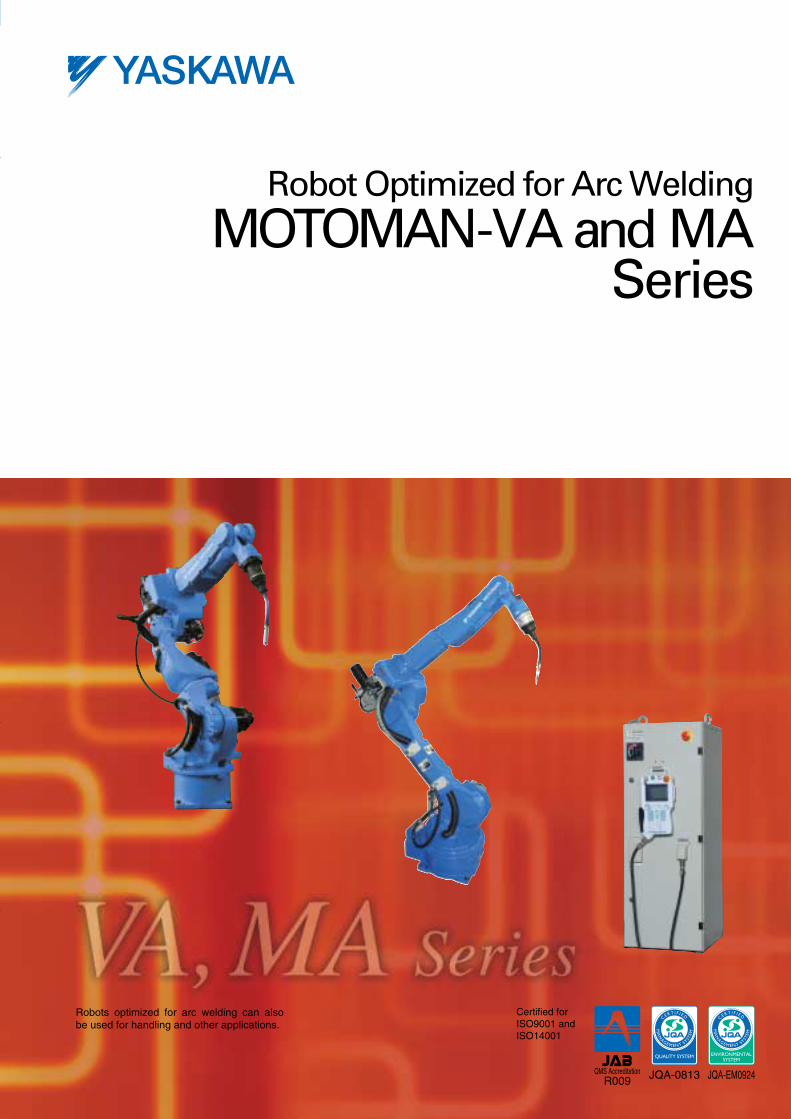
Robot Optimized for Arc Welding
MOTOMAN-VA and MASeries
Certified for ISO9001 andISO14001
Robots optimized for arc welding can also be used for handling and other applications.
Hardware
Software
Cube interference zone Cube interference zone
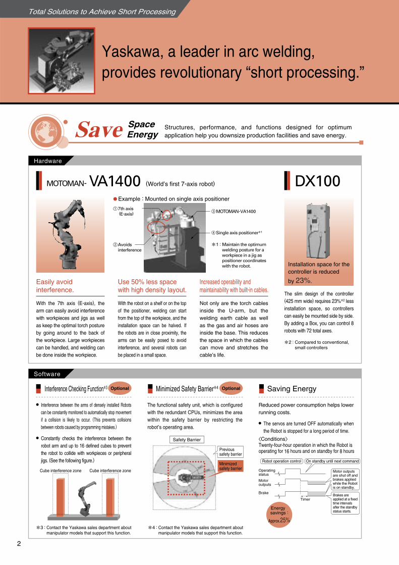
Structures, performance, and functions designed for optimum application help you downsize production facilities and save energy.Save Space
Energy
Interference Checking Function3
The slim design of the controller (425 mm wide) requires 23%
2 less installation space, so controllers can easily be mounted side by side. By adding a Box, you can control 8 robots with 72 total axes.
The functional safety unit, which is configured with the redundant CPUs, minimizes the area within the safety barrier by restricting the robot’s operating area.
Reduced power consumption helps lower running costs.
MOTOMAN- (World’s first 7-axis robot)VA1400 DX100
Minimized Safety Barrier4 Saving Energy
Easily avoidinterference.
Use 50% less spacewith high density layout.
With the robot on a shelf or on the top of the positioner, welding can start from the top of the workpiece, and the installation space can be halved. If the robots are in close proximity, the arms can be easily posed to avoid interference, and several robots can be placed in a small space.
Increased operability andmaintainability with built-in cables.
Not only are the torch cables inside the U-arm, but the welding earth cable as well as the gas and air hoses are inside the base. This reduces the space in which the cables can move and stretches the cable’s life.
The servos are turned OFF automatically when the Robot is stopped for a long period of time.
Constantly checks the interference between the robot arm and up to 16 defined cubes to prevent the robot to collide with workpieces or peripheral jigs. (See the following figure.)
Interference between the arms of densely installed Robots can be constantly monitored to automatically stop movement if a collision is likely to occur. (This prevents collisions between robots caused by programming mistakes.)
Compared to conventional, small controllers
Robot operation control
Operating status
Motor outputs
Brake
Timer
On standby until next command
Motor outputs are shut off and brakes applied while the Robot is on standby.
Brakes are applied at a fixed time intervals after the standby status starts.
〈Conditions〉 Twenty-four-hour operation in which the Robot isoperating for 16 hours and on standby for 8 hours
Optional Optional
Example : Mounted on single axis positioner
Maintain the optimum welding posture for a workpiece in a jig as positioner coordinates with the robot.
7th axis (E-axis)
13 MOTOMAN-VA1400
4 Single axis positioner1
2 Avoidsinterference
With the 7th axis (E-axis), the arm can easily avoid interference with workpieces and jigs as well as keep the optimal torch posture by going around to the back of the workpiece. Large workpieces can be handled, and welding can be done inside the workpiece.
Safety Barrier
1 :
2 :
Previoussafety barrier
Minimized safety barrier
Energy savings :
Approx.25%
Installation space for thecontroller is reduced
by 23%.
3 : Contact the Yaskawa sales department about manipulator models that support this function.
4 : Contact the Yaskawa sales department about
manipulator models that support this function.
Total Solutions to Achieve Short Processing
Yaskawa, a leader in arc welding,provides revolutionary “short processing.”
2
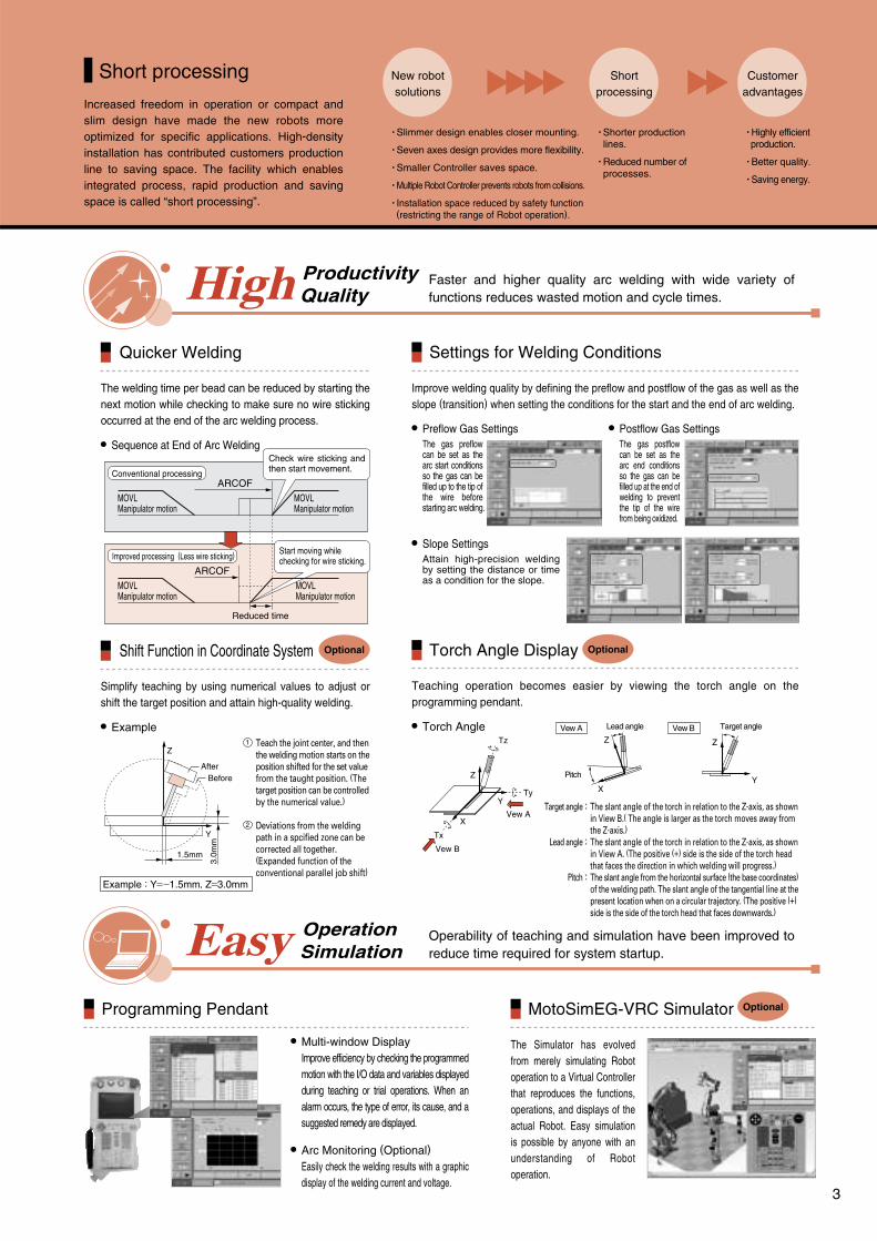
Faster and higher quality arc welding with wide variety of functions reduces wasted motion and cycle times.High Productivity
Quality
Operability of teaching and simulation have been improved to reduce time required for system startup.Easy Operation
Simulation
The Simulator has evolved from merely simulating Robot operation to a Virtual Controller that reproduces the functions, operations, and displays of the actual Robot. Easy simulation is possible by anyone with an understanding of Robot operation.
Programming Pendant MotoSimEG-VRC Simulator Optional
Settings for Welding ConditionsQuicker Welding
The welding time per bead can be reduced by starting the next motion while checking to make sure no wire sticking occurred at the end of the arc welding process.
Sequence at End of Arc Welding
Improve welding quality by defining the preflow and postflow of the gas as well as the slope (transition) when setting the conditions for the start and the end of arc welding.
Slope SettingsAttain high-precision welding by setting the distance or time as a condition for the slope.
Torch Angle DisplayShift Function in Coordinate System
Simplify teaching by using numerical values to adjust or shift the target position and attain high-quality welding.
Example
Teaching operation becomes easier by viewing the torch angle on the programming pendant.
Torch Angle
Optional Optional
Multi-window DisplayImprove efficiency by checking the programmed motion with the I/O data and variables displayed during teaching or trial operations. When an alarm occurs, the type of error, its cause, and a suggested remedy are displayed.
Arc Monitoring (Optional) Easily check the welding results with a graphic display of the welding current and voltage.
MOVLManipulator motion
MOVLManipulator motion
MOVLManipulator motion
ARCOF
Check wire sticking and then start movement.
MOVLManipulator motion
ARCOF
Start moving while checking for wire sticking.
Conventional processing
Improved processing (Less wire sticking)
Reduced time
The gas preflow can be set as the arc start conditions so the gas can be filled up to the tip of the wire before starting arc welding.
The gas postflow can be set as the arc end conditions so the gas can be filled up at the end of welding to prevent the tip of the wire from being oxidized.
Preflow Gas Settings Postflow Gas Settings
Teach the joint center, and then the welding motion starts on the position shifted for the set value from the taught position. (The target position can be controlled by the numerical value.)
Deviations from the welding path in a spcified zone can be corrected all together. (Expanded function of the conventional parallel job shift)
Z
Y
1.5mm
3.0m
m
Example : Y=−1.5mm, Z=3.0mm
AfterBefore Z
Tz
TyY
Tx
XVew A
Vew B
Lead angle Target angleVew A Vew BZ Z
YX
Pitch
1
2
Target angle
Lead angle
Pitch
:
:
:
The slant angle of the torch in relation to the Z-axis, as shown in View B.( The angle is larger as the torch moves away from the Z-axis.)The slant angle of the torch in relation to the Z-axis, as shown in View A. (The positive (+) side is the side of the torch head that faces the direction in which welding will progress.)The slant angle from the horizontal surface (the base coordinates) of the welding path. The slant angle of the tangential line at the present location when on a circular trajectory. (The positive (+) side is the side of the torch head that faces downwards.)
Increased freedom in operation or compact and slim design have made the new robots more optimized for specific applications. High-density installation has contributed customers production line to saving space. The facility which enables integrated process, rapid production and saving space is called “short processing”.
Short processing
・Slimmer design enables closer mounting.
・Seven axes design provides more flexibility.
・Smaller Controller saves space.
・Multiple Robot Controller prevents robots from collisions.
・Installation space reduced by safety function (restricting the range of Robot operation).
・Shorter production lines.
・Reduced number of processes.
・Highly efficient production.
・Better quality.
・Saving energy.
Customeradvantages
Shortprocessing
New robotsolutions
3
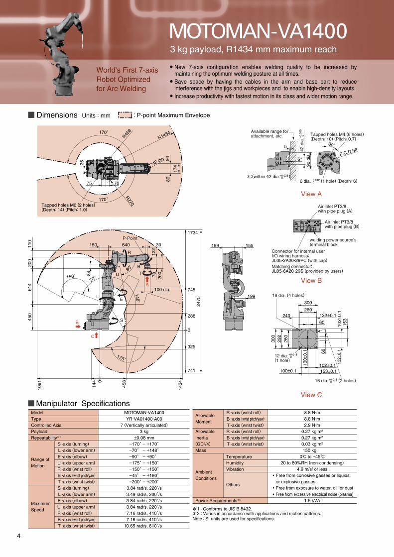
Manipulator SpecificationsMOTOMAN-VA1400YR-VA01400-A00
7 (Vertically articulated)
3 kg±0.08 mm
−170˚ − +170˚−70˚ − +148˚−90˚ − +90˚−175˚ − +150˚−150˚ − +150˚−45˚ − +180˚−200˚ − +200˚
3.84 rad/s, 220˚/s3.49 rad/s, 200˚/s3.84 rad/s, 220˚/s3.84 rad/s, 220˚/s7.16 rad/s, 410˚/s7.16 rad/s, 410˚/s
10.65 rad/s, 610˚/s
View A
View B
View C
Connector for internal userI/O wiring harness: JL05-2A20-29PC (with cap)Matching connector:JL05-6A20-29S (provided by users)
Air inlet PT3/8with pipe plug (A)
Air inlet PT3/8with pipe plug (B)
welding power source’s terminal block
1BC
2BC
3BC
90 d
ia.
30˚5
42 d
ia.
6P.C.D.56
60
132±0.1
153±0.1102±0.1
300
292
260
100±0.1
130±
0.1
132±
0.1
102±
0.1260
300
153
240
60
:(within 42 dia. )
Tapped holes M4 (6 holes)(Depth: 10) (Pitch: 0.7)
6 dia. (1 hole) (Depth: 6)
Available range forattachment, etc.
200
2475
1734
745
288
0
325
741
80˚
1081 144 0
458
1434
122
78
30
175˚
148˚
70˚150˚
150
U
L
S
100 dia.
170˚
170˚
75 70
42 dia.
36
84
P-Point
R270
R458
R1434
Tapped holes M6 (2 holes)(Depth: 14) (Pitch: 1.0)
A
B
C
640
B
T
155199
199
110
200
614
450
E
R
Range ofMotion
MaximumSpeed
ModelTypeControlled AxisPayloadRepeatability1
-axis (turning)
-axis (lower arm)
-axis (elbow)
-axis (upper arm)
-axis (wrist roll)
-axis (wrist pitch/yaw)
-axis (wrist twist)
-axis (turning)
-axis (lower arm)
-axis (elbow)
-axis (upper arm)
-axis (wrist roll)
-axis (wrist pitch/yaw)
-axis (wrist twist)
SLEURBTSLEU RBT
Allowable Moment
Allowable Inertia(GD2/4)
Mass
AmbientConditions
8.8 N·m 8.8 N·m 2.9 N·m
0.27 kg·m2
0.27 kg·m2
0.03 kg·m2
150 kg0 C to +45 C
20 to 80%RH (non-condensing)
4.9 m/s2 or less
1.5 kVA
Free from corrosive gasses or liquids, or explosive gassesFree from exposure to water, oil, or dustFree from excessive electrical noise (plasma)
12
::Conforms to JIS B 8432.Varies in accordance with applications and motion patterns.
TemperatureHumidityVibration
Others
Power Requirements2
Note : SI units are used for specifications.
-axis (wrist roll)
-axis (wrist pitch/yaw)
-axis (wrist twist)
-axis (wrist roll)
-axis (wrist pitch/yaw)
-axis (wrist twist)
RBTRBT
18 dia. (4 holes)
+0.025 0
+0.012 0
16 dia. (2 holes)+0.018 0
12 dia. (1 hole)
+0.018 0
+ 0.0
25 0
9480
174 42
dia
.
MOTOMAN-VA14003 kg payload, R1434 mm maximum reach
New 7-axis configuration enables welding quality to be increased by maintaining the optimum welding posture at all times. Save space by having the cables in the arm and base part to reduce interference with the jigs and workpieces and to enable high-density layouts.Increase productivity with fastest motion in its class and wider motion range.
World’s First 7-axis Robot Optimized for Arc Welding
Dimensions Units : mm : P-point Maximum Envelope
4
Tapped holes M4 (6 holes)(Depth: 10) (Pitch: 0.7)
6 dia. (1 hole) (Depth: 6)
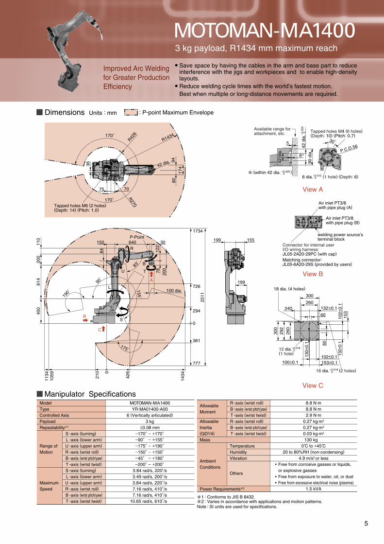
Manipulator SpecificationsMOTOMAN-MA1400YR-MA01400-A00
6 (Vertically articulated)
3 kg±0.08 mm
−170˚ − +170˚−90˚ − +155˚−175˚ − +190˚−150˚ − +150˚−45˚ − +180˚−200˚ − +200˚
3.84 rad/s, 220˚/s3.49 rad/s, 200˚/s3.84 rad/s, 220˚/s7.16 rad/s, 410˚/s7.16 rad/s, 410˚/s
10.65 rad/s, 610˚/s
View A
View B
View C
Connector for internal userI/O wiring harness:JL05-2A20-29PC (with cap)Matching connector:JL05-6A20-29S (provided by users)
Air inlet PT3/8with pipe plug (A)
Air inlet PT3/8with pipe plug (B)
welding power source’s terminal block
1BC
2BC
3BC
90 d
ia.
30˚5
6P.C.D.56
42 d
ia.
60
132±0.1
153±0.1102±0.1
300
292
260
100±0.1
130±
0.1
132±
0.1
102±
0.1260
300
153
240
60
Available range forattachment, etc.
200
2511
1734
726
294
0
361
777
83˚
1134
1059 210 0
426
1434
110
122
78
30
175˚
155˚
90˚
190˚
640150
200
614
450
B
T
R
U
L
S
100 dia.
155199
199
170˚
170˚
75 70
36
84
P-Point
R270
R426
R1434
Tapped holes M6 (2 holes)(Depth: 14) (Pitch: 1.0)
A
B
C
Allowable Moment
Allowable Inertia(GD2/4)
Mass
AmbientConditions
8.8 N·m 8.8 N·m 2.9 N·m
0.27 kg·m2
0.27 kg·m2
0.03 kg·m2
130 kg0 C to +45 C
20 to 80%RH (non-condensing)
4.9 m/s2 or less
1.5 kVA
Free from corrosive gasses or liquids, or explosive gassesFree from exposure to water, oil, or dustFree from excessive electrical noise (plasma)
::Conforms to JIS B 8432.Varies in accordance with applications and motion patterns.
TemperatureHumidityVibration
Others
Power Requirements2
Note : SI units are used for specifications.
-axis (wrist roll)
-axis (wrist pitch/yaw)
-axis (wrist twist)
-axis (wrist roll)
-axis (wrist pitch/yaw)
-axis (wrist twist)
RBTRBT
Range ofMotion
MaximumSpeed
ModelTypeControlled AxisPayloadRepeatability1
-axis (turning)
-axis (lower arm)
-axis (upper arm)
-axis (wrist roll)
-axis (wrist pitch/yaw)
-axis (wrist twist)
-axis (turning)
-axis (lower arm)
-axis (upper arm)
-axis (wrist roll)
-axis (wrist pitch/yaw)
-axis (wrist twist)
SLURBTSLU RBT
18 dia. (4 holes)
42 d
ia.+ 0
.025
0
+0.012 0
:(within 42 dia. )+0.025
0
16 dia. (2 holes)+0.018 0
12 dia. (1 hole)
+0.018 0
12
9480
17442 dia.
MOTOMAN-MA14003 kg payload, R1434 mm maximum reach
Save space by having the cables in the arm and base part to reduce interference with the jigs and workpieces and to enable high-density layouts.Reduce welding cycle times with the world’s fastest motion.Best when multiple or long-distance movements are required.
Improved Arc Welding for Greater Production Efficiency
Dimensions Units : mm : P-point Maximum Envelope
5
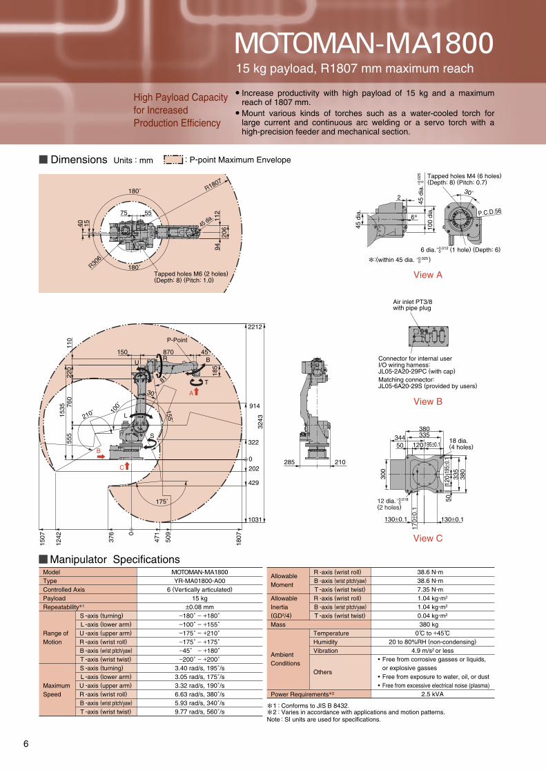
View A
View B
View C
45 d
ia.
Air inlet PT3/8with pipe plug
Connector for internal userI/O wiring harness:JL05-2A20-29PC (with cap) Matching connector:JL05-6A20-29S (provided by users)
Manipulator SpecificationsMOTOMAN-MA1800YR-MA01800-A00
6 (Vertically articulated)
15 kg±0.08 mm
−180˚ − +180˚−100˚ − +155˚−175˚ − +210˚−175˚ − +175˚−45˚ − +180˚−200˚ − +200˚
3.40 rad/s, 195˚/s3.05 rad/s, 175˚/s3.32 rad/s, 190˚/s6.63 rad/s, 380˚/s5.93 rad/s, 340˚/s9.77 rad/s, 560˚/s
335380
120
50
130±0.1 130±0.1
335
380
1205019
5±0.
1344
5575
R306
40 15
180˚
180˚
206
112
946
2
P.C.D.56
30˚
3BC
1BC
2BC
AIR
300
285 210
100
dia.
195±0.1
170±
0.1
P-Point
T
BU
L
150 870 45
555
760
1535 100˚
155˚81
˚
1807376
1242
1507 0
509
202
429
1031
0
471
322
914
2212
3243
175˚
110
210˚
S
30˚
185
220
C
B
A
Tapped holes M4 (6 holes)(Depth: 8) (Pitch: 0.7)
6 dia. (1 hole) (Depth: 6)
R
Allowable Moment
Allowable Inertia(GD2/4)
Mass
AmbientConditions
38.6 Nm38.6 Nm7.35 Nm1.04 kgm2
1.04 kgm2
0.04 kgm2
380 kg0 C to +45 C
20 to 80%RH (non-condensing)
4.9 m/s2 or less
2.5 kVA
12
::Conforms to JIS B 8432.Varies in accordance with applications and motion patterns.
TemperatureHumidityVibration
Others
Power Requirements2
Note : SI units are used for specifications.
-axis (wrist roll)
-axis (wrist pitch/yaw)
-axis (wrist twist)
-axis (wrist roll)
-axis (wrist pitch/yaw)
-axis (wrist twist)
RBTRBT
Range ofMotion
MaximumSpeed
ModelTypeControlled AxisPayloadRepeatability1
-axis (turning)
-axis (lower arm)
-axis (upper arm)
-axis (wrist roll)
-axis (wrist pitch/yaw)
-axis (wrist twist)
-axis (turning)
-axis (lower arm)
-axis (upper arm)
-axis (wrist roll)
-axis (wrist pitch/yaw)
-axis (wrist twist)
SLURBTSLU RBT
Tapped holes M6 (2 holes)(Depth: 8) (Pitch: 1.0)
18 dia.(4 holes)
45 d
ia.+ 0
.025
0
12 dia. (2 holes)
+0.018 0
+0.012 0
:(within 45 dia. )+0.025
0
45 dia.
R1807
Free from corrosive gasses or liquids, or explosive gassesFree from exposure to water, oil, or dustFree from excessive electrical noise (plasma)
MOTOMAN-MA1800
High Payload Capacity for Increased Production Efficiency
Increase productivity with high payload of 15 kg and a maximum reach of 1807 mm.Mount various kinds of torches such as a water-cooled torch for large current and continuous arc welding or a servo torch with a high-precision feeder and mechanical section.
15 kg payload, R1807 mm maximum reach
Dimensions Units : mm : P-point Maximum Envelope
6
Manipulator SpecificationsMOTOMAN-MA1900YR-MA01900-A00
6 (Vertically articulated)
3 kg±0.08 mm
−180˚ − +180˚−110˚ − +155˚−165˚ − +220˚−150˚ − +150˚−45˚ − +180˚−200˚ − +200˚
3.44 rad/s, 197˚/s3.05 rad/s, 175˚/s3.23 rad/s, 185˚/s7.16 rad/s, 410˚/s7.16 rad/s, 410˚/s
10.65 rad/s, 610˚/s
1BC
3BC
2BC
A
C
B
155
260 157
375
60313
335
200±
0.1
260±0.1
6033
537
5
200±0.1
170±
0.1
3437
Air inlet PT3/8with pipe plug
Connector for internal userI/O wiring harness: JL05-2A20-29PC (with cap)Matching connector:JL05-6A20-29S (provided by users)
View A
Available range forattachment, etc.
90 d
ia.
5
6
42 d
ia. P.C.D.56
30˚
R1904
180˚
R554
75 55
180˚
1540
Tapped holes M6 (2 holes)(Depth: 12) (Pitch: 1.0)
1604 1166 409
970 30
0
150
554
200
1904
U
B
T
P-Point
81˚
L
110˚ 155˚
220
760
1485
220˚ S
505
165˚
View C
View B
2259
0
647
1178
R
Range ofMotion
MaximumSpeed
ModelTypeControlled AxisPayloadRepeatability1
-axis (turning)
-axis (lower arm)
-axis (upper arm)
-axis (wrist roll)
-axis (wrist pitch/yaw)
-axis (wrist twist)
-axis (turning)
-axis (lower arm)
-axis (upper arm)
-axis (wrist roll)
-axis (wrist pitch/yaw)
-axis (wrist twist)
SLURBTSLU RBT
Allowable Moment
Allowable Inertia(GD2/4)
Mass
AmbientConditions
8.8 N·m 8.8 N·m 2.9 N·m
0.27 kg·m2
0.27 kg·m2
0.03 kg·m2
280 kg0 C to +45 C
20 to 80%RH (non-condensing)
4.9 m/s2 or less
2.0 kVA
12
::Conforms to JIS B 8432.Varies in accordance with applications and motion patterns.
TemperatureHumidityVibration
Others
Power Requirements2
Note : SI units are used for specifications.
-axis (wrist roll)
-axis (wrist pitch/yaw)
-axis (wrist twist)
-axis (wrist roll)
-axis (wrist pitch/yaw)
-axis (wrist twist)
RBTRBT
18 dia.(4 holes)
12 dia. (2 holes)
+0.018 0
Tapped holes M4 (6 holes)(Depth: 10) (Pitch: 0.7)
6 dia. (1 hole) (Depth: 6)
42 d
ia.+ 0
.025
0
+0.012 0
:(within 42 dia. )+0.025
0
9480
17442 dia.
Free from corrosive gasses or liquids, or explosive gassesFree from exposure to water, oil, or dustFree from excessive electrical noise (plasma)
MOTOMAN-MA1900
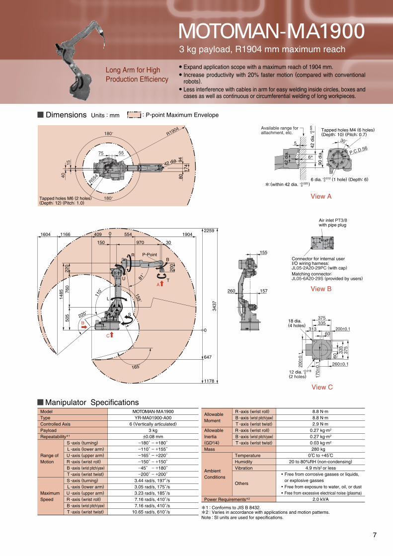
Long Arm for High Production Efficiency
Expand application scope with a maximum reach of 1904 mm.Increase productivity with 20% faster motion (compared with conventional robots).Less interference with cables in arm for easy welding inside circles, boxes and cases as well as continuous or circumferential welding of long workpieces.
3 kg payload, R1904 mm maximum reach
Dimensions Units : mm : P-point Maximum Envelope
7
MOTOMAN-VA and MA Series
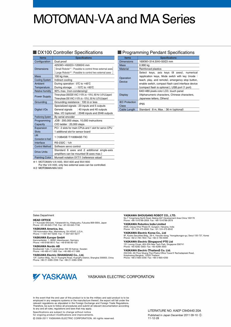
SpecificationsDust proof425(W)×450(D)×1200(H) mm Small Robots1 : Possible to control three external axesLarge Robots2 : Possible to control two external axes
100 kg max. Indirect coolingDuring operation : 0 C to +45 C During storage : −10 C to +60 C 90% max. (non-condensing)
Three-phase 200/220 VAC (+10% to −15%), 60 Hz (±2%)(Japan)
Three-phase 200 VAC (+10% to −15%), 50 Hz (±2%)(Japan)
Grounding resistance : 100 Ω or lessSpecialized signals : 23 inputs and 5 outputsGeneral signals : 40 inputs and 40 outputsMax. I/O (optional) : 2048 inputs and 2048 outputsBy serial encoderJOB : 200,000 steps, 10,000 instructionsCIO ladder : 20,000 stepsPCI : 2 slots for main CPUs and 1 slot for servo CPU1 additional slot for sensor board
1 (10BASE-T/100BASE-TX)
RS-232C : 1chSoftware servo controlStandard 6 axes and 2 additional single-axis amplifiers can be mounted (8 axes max.)
Munsell notation 5Y7/1 (reference value)
ItemsConfiguration
Dimensions
MassCooling SystemAmbient TemperatureRelative Humidity
Power Supply
Grounding
Digital l/Os
Positioning SystemProgramming CapacityExpansion SlotsLAN(Connection to Host)
InterfaceControl Method
Drive Units
Painting Color
DX100 Controller SpecificationsSpecifications
169(W)×314.5(H)×50(D) mm0.990 kgReinforced plasticsSelect keys, axis keys (8 axes), numerical /application keys, Mode switch with key (mode :
teach, play, and remote), emergency stop button, enable switch, compact flash card interface device (compact flash is optional.), USB port (1 port) 640×480 pixels color LCD, touch panel(Alphanumeric characters, Chinese characters, Japanese letters, Others)
IP65
Standard : 8 m, Max. : 36 m (optional)
ItemsDimensionsMassMaterial
Operation Device
Display
IEC Protection Class Cable Length
Programming Pendant Specifications
MOTOMAN-VA1400, MA1400 and MA1900For the VA1400, only two external axes can be controlled. MOTOMAN-MA1800
1
2
:
:


![Journal of American Science 0203arc welding, atomic hydrogen welding, shielded metal arc welding, plasma arc welding, electroslag welding, etc. Arc welding has been described [3] to](https://img.pdfslide.net/doc/110x75/5ec0a6e76045b75960496969/journal-of-american-science-arc-welding-atomic-hydrogen-welding-shielded-metal.jpg)