Embed Size (px)
Citation preview

P ro d u c t L i n e u p
iVYSystem
ROBOT VISION iVYEasy to use and reduction of work steps."Finds and Picks up" and "Pursues and Picks up" without teaching.
Many robot users might think, "We tried vision recognition, but it seemed to take a lot of work" or "we tried it before, but making adjustments was a tough job". But YAMAHA iVY system solves these problems. Anyone can make the setup easily to contribute to reduction of work steps.
RCX240
72

73
i V Y s y s t e m l a y o u tA robot controller with an image processing function is completed only by setting the iVY board in the 4-axis controller RCX240 or RCX240S. As "eye" is put in the robot, the robot finds and takes workpiece, checks deviations in workpiece position, and makes correction if the workpiece deviates largely. This expands the range of applications.
Programming box RPB
Robot
PC
SoftwareiVY Studio
iVY board
• Tracking board
• Lighting control board
2 cameras2 cameras 2 lights
Encoder Encoder
Up to two encoders can be connected.
Either optional tracking board or lighting control board can be selected.(Tracking board is equipped with lighting control function.)
Vision board connectsdirectly to bus
Up to two cameras and lights can be connected.
Multi-axis controller
■ Options
• Lighting control board
• Tracking board
• CCD camera
• LAN cable (Shielded cross-cable)
• Camera cable
• Lens
• Close-up ring
Lens
CCD camera
Tracking board
■ Positioning by searching for workpiece ■ Automatic correction even if the camera moves ■ Applicable to conveyor tracking
Detection by camera + pick-up Assembly
Positioning is not needed.
Pick-up
Workpiece 1
Workpiece 2
Workpiece 3
Assembly
Positioning by workpiece
Conventional system without robot vision
When the workpiece is changed, the positioning jig replacement work is needed.In particular, when using a small lot of workpieces, the setup costs or jig manufacture and management costs are needed.
Even when the workpiece is changed, it is flexibly supported only by changing the part type data.Since no mechanical positioning is needed, cost reductions, such as equipment down-sizing or jig cost reduction become possible.
System with robot vision

i V Y S y s t e m P r o d u c t L i n e u p
74
P O I N T 1
Easy for anyone to use, applicable to a wide variety of applications
When the system was upgraded by combining the robot with a generally available image processing unit, it took a long time conventionally to adjust the robot controller and image processing unit, and perform the correction calculation. In YAMAHA "iVY system", the vision board is integrated into the robot controller and the functions are limited to the positioning and position correction so as to greatly simplify the operability. This makes the system incredibly easy to use when compared to conventional vision systems. YAMAHA aimed at "a vision system that anyone can easily use". Please try to use YAMAHA's new robot vision.
➀ Alignment with robot coordinates is difficult.
➁ Correction calculation is needed when the camera moves.
➂ Operation deviation between the camera and robot due to comunication time.
➃ Adjustment of communication format is needed.
➀ Simple calibration function is incorporated.
➁ Coordinates are corrected automatically even when the camera moves.
➂ High-speed connections through dedicated bus line.
➃ Controller is incorporated to provide the central operation.
➄ Applicable to all models of YAMAHA robot lineup.
Camera cable
Camera
Power supply for lighting
Light
Image processing unit
Robot Robot
Camera cable
CameraLight
RCX240
iVY board
Lighting control board
RS-232C communication
Connecting an external camera to the robot controller requires tasks such as coordinate alignment (calibration), and correction programs are needed, so the startup work is difficult. When using for simple applications, many work steps are needed. So, possible applications are limited.
YAMAHA iVY system can be calibrated very simplyFurthermore, the coordinates are corrected automatically when a camera is installed on the robot. As iVY system can be used, it can be applied to various applications.
Point
Special skills are required and many work steps are needed. Easy operation extends applicationsEasy operation extends applicationsEasy operation extends applicationsEasy operation extends applications
• Easy to use• Various applications are supported using easy operation.
• Cost reduction by reducing work steps.• YAMAHA gives you total support.
• Difficult to handle.• Hard to actually operate.
• Installation and setup costs are high.• Difficult to know emergency contact address.
Conventional robot vision iVY system
P O I N T 2
Easy workpiece registration only with 3 steps
YAMAHA aimed at "a vision system that anyone can easily use". But, image recognition itself has been around for a long time. However, conventional image recognition required complex tasks such as coordinate matching (calibration) or coordinate correction during camera movement, and it never became very popular. YAMAHA vision iVY System can be operated by anyone including machine designers or actual machine operators.
Capture images.
STEP. 1
Set the contour.
STEP. 2
Register the detection position.
STEP. 3 Search results
Put the workpiece within the camera field-of-view and specify an image capturing range.
Contour is automatically extracted. Paint the necessary contour with a pen tool.
Specify the detection position with the mouse.Desired positions can be set.

75
P O I N T 4
Simple calibration function (coordinate matching alignment work) incorporated
Conventional equipment combining "image processing unit + robot" requires many steps in "calibration" that aligns the camera coordinates with the robot coordinates. In the iVY system, the operation is completed easily in a short time only by following interactive instructions using the programming box. Additionally, the coordinate values are corrected automatically even when the robot installation position is changed, such as upward clamping, downward clamping, robot Z-axis clamping, or SCARA robot Y-arm clamping.
Just follow instructions on Wizards
P O I N T 5
Setup time reduced greatly
When using a general vision, a coordinate conversion program needs to be created in the robot controller since the robot coordinate data differs from the vision format.Since the robot controller is integrated into the iVY system, the robot coordinate data can be stored into the robot point data using single process. This ensures very simple operation. Additionally, the unified control of the camera control and light control can be performed using the robot program. The control becomes easy and the number of start-up steps can also be reduced.
Installation
Pattern registration
Calibration
Setup time is shortened greatly
Communication setting
Parameter setting
Program setting
Debug
Comparison of setup time
iVY system
Days
General-purpose vision
P O I N T 3
Dedicated software "iVY Studio" included
The iVY system includes dedicated software "iVY Studio". All operations related to the vision, such as registration of fiducial marks used for the calibration or workpieces (edge setting, various parameter setting, and image capturing range setting, etc.), backup, restore, and operation monitor can be performed only with this software.
● Search trial-run, part type registration
● Reference mark registration (for calibration)
● Up to 40 workpiece types can be registered.
● Workpiece can also be added easily.
● Up to 40 workpieces can be detected at once.
● Data backup
● This software functions as a monitor during program operation.
S u p p o r t s o f t w a r e i V Y S t u d i o
■ Single-axis robots FLIP-X ■ Linear motor
single-axis robots
PHASER
■ Cartesian robots XY-X ■ SCARA robots YK-XG
P O I N T 6
Free selection from YAMAHA robot lineup
This robot vision is applicable to all YAMAHA robots that can be operated by the RCX controller.According to the applications, an appropriate robot can be selected from the single-axis robots FLIP-X series, linear single-axis robots PHASER series, Cartesian robots XY-X, and SCARA robots YK-XG. A low-cost and easy-to-use robot vision system can be constructed with an optimal model suitable for applications.

i V Y S y s t e m P r o d u c t L i n e u p
76
P O I N T 7
Workpiece handling without teaching
When the robot handles a workpiece, the teaching work to the correct position is absolutely required. If the workpiece position deviates, the correct handling cannot be performed.Use of iVY system makes it possible to detect the correct position through the image recognition after coarse positioning. The workpiece can be transferred without teaching, so the start-up steps are reduced and workpiece can be changed or added flexibly.
P O I N T 8
Edge search engine with excellent stability
The gray search (normalized correlation search) that was frequently used for conventional visions is vulnerable to adverse effects, such as lighting conditions, or workpiece chipping or contamination. The environments and applications are restricted.The iVY system incorporates an "edge search engine" that performs the search process using information on contour shape. This contour search is resistant to effects on external environment and the range of applications is extended.
P O I N T 9
High-speed connections through dedicated bus line
By directly connecting the robot controller and CPU board through the bus, a data communication speed approximately 5,000 times higher than that of the serial communication speed with general vision is achieved.Programming also becomes easy since the time lag due to communication does not need to be considered. Additionally, this robot vision supports the conveyor tracking that requires high-speed processing.
RS-232C
Dedicated bus line
Data transmission volume per second
19200 bit
100 Mbit100 Mbit
P O I N T 1 0
Applicable to conveyor tracking
The iVY system is applicable to the conveyor tracking only by adding the tracking board. As the pulses (AB-phase) are taken from the encoder installed on the conveyor, the workpiece that is flowing can be picked up without stopping the conveyor.As up to two encoders for the camera, lighting, and conveyor can be connected, the iVY system is applicable to movement between the conveyors.
Collection conveyorPallet
Supply conveyor Palletizing robot
CCD camera
Search is made with good lighting. Search is correct even with insufficient lightning.

So, the iVY system can solve such problems.
Number of teaching steps needs to be reduced.
Robot teaching work requires a lot of labor and time. The iVY
system acts as "robot eye". The final fine positioning can be
automated to greatly reduce the teaching time that was required
for the conventional models.
Workpiece flowing on the conveyor is picked up.
The iVY system is applicable to conveyor tracking. The position
of the flowing workpiece is continuously recognized according to
the signals from the encoder. The workpiece can be picked up
without stopping the conveyor.
Positioning mechanism needs to be simplified.
In the current trend toward small-lot production of multiple mod-
els, a larger number of models means that positioning and other
aspects of setup will require more time and trouble. Use of the iVY
system makes it possible to greatly reduce costs necessary for
manufacture, management, and replacement of positioning jigs.
Consultation destination is not found if a trouble occurs.
When a generally available image processing unit is combined
with the robot, various problems such as being unable to cap-
ture images, unable to write data, or position deviation occur.
YAMAHA iVY system will solve such troubles. The iVY system
delivers total support for tasks ranging from capturing of images
from the camera to operating the robot.Random workpieces need to be handled.
Use of a position detection function of the iVY system makes it
possible to simply construct operations, such as "workpiece is
directly placed from the parts feeder" and "workpiece in the pal-
let is gripped and transferred".
77
P O I N T 11
Vision is also controlled easily with robot programs.
The robot program executes all vision controls including camera switching, image capturing, and workpiece search.Program creation is simple when compared to general vision systems since the operations from the robot movement to the camera control are performed consistently.Furthermore, the debug work can be performed efficiently to greatly reduce the total number of work steps.
■ Example of robot vision language
Command name Function
VCAPTURE Captures images from the camera.
VSEARCH Searches for the specified part type.
VMONITOR Switches the monitor mode between on and off.
VGETCNT Acquires the number of parts that were found.
VGETPOS Acquires the position data.
VGETTIME Acquires a period of time used for the search command that was executed.
VGETSCR Acquires judgment values for the detected workpiece.
VSAVEIMG Saves images in BMP format.
RS-232C
Program of image processing unit
Program of host PLC
MOVE P, P9VSEARCH 1,2,0P10=VGETPOS(0)MOVE P, P10
Searches for workpiece.Reads the point.Moves to this point.
Communication with image processing unit
MOVE P, P9OFF LINESEND (* *) TO CMUSEND CMU TO P10ON LINEMOVE P, P10
MERITS
● No communication time lag● Controllable only with the robot program.● Needs only few command lines.● Simple and easy to understand
Controls using different programs Centralized controls using robot programsCentralized controls using robot programsCentralized controls using robot programsCentralized controls using robot programs
Conventional robot vision iVY system

Articulate
d rob
ots
YA
Co
mp
act
sing
le-a
xis rob
ots
TRAN
SERVOS
ing
le-a
xis rob
ots
FLIP-X
Lin
ea
r mo
tor
sing
le-a
xis rob
ots
PHA
SER
Ca
rtesia
nro
bo
ts
XY-X
SC
AR
Aro
bo
ts
YK
-X
Pick &
pla
cero
bo
ts Y
P-XC
LEAN
CON
TROLLER
INFORM
ATION
Lin
ea
r conveyo
r m
od
ule
s
LCM
100
572
Ro
bo
t p
ositio
ne
rP
ulse string driver
Ro
bo
tco
ntro
ller
iVY
Op
tion
iVY System
“SEARCH and TAKE” “CHECK POSITION and ASSEMBLE” YAMAHA offers a whole new production line concept that eliminates time-consuming teaching and positioning tasks with “iVY-system”.
ROBOT VISION
■ Ordering method
Applicable controllers RCX240/RCX240S
■ Basic specifications
● iVY board
Item iVY board
Ba
sic
spe
cific
atio
ns
Applicable controllers RCX240 / RCX240S
Pixels 640 (H) × 480 (V) (300,000 pixels, VGA)
Settable part types 40 part types
Connectable camerasMaximum 2 unitsNote. Note. If connecting 2 units, then must be
the same model
Camera types Double speed compatible analog camera
Memory 128MB SDRAM, 256MB miniSD card
External I/F Ethernet (100BASE-TX)
Search method Edge search (Correlative edge filter, Sobel filter)
Image inputTrigger S/W trigger, H/W trigger, Camera internal synch
External trigger input 2 points
FunctionsSearch function Position offset, Auto registry of point data
ID recognition (usage planned) QR-Code [Model2], DataMatrix
Setup support functionsCalibration, image save function, model registrationNote, fiducial mark registrationNote, monitor functionNote
Note. Requires Windows PC.
● Lighting control board (option)
Item Lighting control board (option)
Ba
sic
spe
cific
atio
ns
Applicable controllers RCX240 / RCX240S
Number of lighting connected units Up to 2 units
Light adjusting system
PWM control (0 to 100%) (Cycle 60kHz)Stroboscopic light (10 to 33000us)
Trigger S/W trigger, H/W trigger
External trigger input 2 points
Lighting power input 12VDC or 24VDC (Supplied from outside commonly to 2 channels)
Lighting output
When DC12V is supplied: Less than 30W with 2 channels totaledWhen DC24V is supplied: Less than 60W with 2 channels totaled
● Tracking board (Options)
Item Tracking board (option)
Ba
sic
spe
cific
atio
ns
Applicable controllers RCX240 / RCX240S
Lig
htin
g co
ntr
ol s
ect
ion
Light adjusting system Up to 2 unitsLight adjustingsystem
PWM control (0 to 100%) (Cycle 60kHz)Stroboscopic light (10 to 33000us)
Trigger S/W trigger, H/W triggerExternal trigger input 2 points
Lighting power input 12VDC or 24VDC (Supplied from outside commonly to 2 channels)
Lighting output
When DC12V is supplied: Less than 30W with 2 channels totaledWhen DC24V is supplied: Less than 60W with 2 channels totaled
Pu
lse
inp
ut s
ect
ion
Number of encoder connected units Up to 2 units
Encoder powersource
DC5V (Less than 500mA with 2 channels totaled) (Supplied from controller)
Applicable encoder Line driver equivalent to 26LS31 / 26C31(Conforming to RS-422)
Input phase A, A, B, B, Z, ZMaximum response frequency 2MHz
Counter / Step-up multiplication 0 to 65535 / Double, quadruple
Other Provided with broken wire detect function
Note. The tracking board is required when using the tracking function.
iVY SYSTEM
iVY System
Main functions P.72
RCX240Controller Usable for CE Regenerative unit Option I/O Network Option iVY System
Option board Light/Tracking Gripper Battery
No entry: None No entry: NoneVY: iVY (VISION) TR: Light+Tracking
LC: Light
Note. For details on the various selection items, refer to P.533
● Robot with image processing functions

Articulate
d rob
ots
YA
Co
mp
act
sing
le-a
xis rob
ots
TRAN
SERVOS
ing
le-a
xis rob
ots
FLIP-X
Lin
ea
r mo
tor
sing
le-a
xis rob
ots
PHA
SER
Ca
rtesia
nro
bo
ts
XY-X
SC
AR
Aro
bo
ts
YK
-X
Pick &
pla
cero
bo
ts YP-X
CLEA
NCO
NTRO
LLERINFO
RMATIO
N
Lin
ea
r conveyo
r m
od
ule
s
LCM
100
573
Ro
bo
t p
ositio
ne
rP
ulse string driver
Ro
bo
tco
ntro
ller
iVY
Op
tion
iVY SystemInstruction manuals can be downloaded from our company website. Please use the following for more detailed information.http://global.yamaha-motor.com/business/robot/
■ Dimensional outlines CCD camera
15
12
2-M2 Depth: 3
Mount Cover
39.5 7.8
13 26.5 1.5
4.4
13.5
Rear panel
29
29±1
C-mount
1220
16 214-M2 Depth: 3
3-M3 Depth: 3
ф2 H7 Depth: 1.5
CCD camera dimensions
(Model No. : KX0-M7913-00)
■ System configuration illustration
RPB
MOTOR
XM
YM
ZM
RM
PWRSRV
SAFETY
RPB
COM
STD.DIO
ROBI/O
ZR
OP.1 OP.3
OP.2 OP.4RGEN
ACIN
N
P
N1L1
LN
SEL
BATTZR
XYBATT
ROB
XY
I/O
13 14EXT.E-STOP
ERR
RCX240
12VDC / 24VDC power supply(according to lighting specs.)
Photoelectric or proximitysensor, etc.
Programming box RPB
YAMAHA robot• Cartesian robot• SCARA robot• Multi-robot (Some functions are restricted.)
Encoder
iVY Studiosoftware
Camera
Lighting
* The above configuration example shows a system where the iVY board and tracking board are used.* Connections to the STD.DIO, ACIN, and SAFETY connectors is not shown in the above illustration.

Articulate
d rob
ots
YA
Co
mp
act
sing
le-a
xis rob
ots
TRAN
SERVOS
ing
le-a
xis rob
ots
FLIP-X
Lin
ea
r mo
tor
sing
le-a
xis rob
ots
PHA
SER
Ca
rtesia
nro
bo
ts
XY-X
SC
AR
Aro
bo
ts
YK
-X
Pick &
pla
cero
bo
ts Y
P-XC
LEAN
CON
TROLLER
INFORM
ATION
Lin
ea
r conveyo
r m
od
ule
s
LCM
100
574
Ro
bo
t p
ositio
ne
rP
ulse string driver
Ro
bo
tco
ntro
ller
iVY
Op
tion
iVY System
Accessories and part optionsiVY System
■ Standard accessories
● iVY board
ModelWithout power supply harness KX0-M4402-10
With power supply harness KX0-M4402-00
● iVY board accessories
Name Single unit model Set ModelCamera trigger input cable connector KX0-M657L-00
KX0-M657K-00Custom tool KX0-M657M-00
● Support software for PC iVY Studio
iVY Studio is support software for the iVY system that allows registering part types and reference marks as well as monitoring the work search status during automatic robot operation by con-necting to the robot controller.
EnvironmentSoftware model KX0-M4988-00
OS Microsoft Windows 2000 / XP / VistaNote. The 64 bit version is not subject to the operation warranty.
CPU Exceeding the environment recommended by the OS being used
Memory 64MB or more (Recommend)
Hard disk Vacant capacity of more than 40MB in the installation destination driveNote. Besides the above, also requires memory space for storing images and data.
Display 800 × 600 dots or more, 32768 colors (16bit High Color) or more (recommended)
Network TCP/IP Ethernet port × 1
Note. If newly adding an iVY, choose the model with harness.
■ Lenses
φ29
34.5 6.7
8mm lens [ML-0813](Model No. : KM7-M7214-60)
φ30
34.5 4
12mm lens [ML-1214] (Model No. : KM7-M7214-40)
φ30
24.5 5.4
16mm lens [ML-1614] (Model No. : KM7-M7214-30)
φ30
24.5 5.6
25mm lens [ML-2514] (Model No. : KM7-M7214-20)
Standard lens angle-of-view table
Focal length (mm)
Aperture value (F No.)
Angle-of-view (degrees)
Closest approach distance
(m)Vertical Horizontal
8mm lens [ML-0813] 8 F1.3-CLOSE 45.0 57.8 0.212mm lens [ML-1214] 12 F1.4-CLOSE 21.9 29.0 0.316mm lens [ML-1614] 16 F1.4-CLOSE 23.0 30.4 0.425mm lens [ML-2514] 25 F1.4-CLOSE 21.6 28.5 0.5
Note. Field-of-view table for our standard lenses. As the field-of-view widens, distortion on image edges may increase.
Viewing angle, WD, and magnification when using close-up ring
Close-up ring
(mm)
8mm lens [ML-0813] 12mm lens [ML-1214]Viewing angle
(mm×mm) WD(mm)
Magnifi-cation
Viewing angle (mm×mm) WD
(mm)Magnifi-cation
Vertical Horizontal Vertical HorizontalNone 72 96 148 0.05 77 103 248 0.05
0.532 43 59 0.11 41 55 125 0.0957 77 115 0.06 89 119 289 0.04
121 27 34 0.18 28 38 80 0.1329 38 52 0.13 45 59 136 0.08
1.526 34 22 0.24 21 29 57 0.1719 26 31 0.19 30 40 85 0.12
2– – – – 17 23 42 0.21– – – – 22 30 59 0.16
5– – – – – – – –– – – – – – – –
Close-up ring
(mm)
16mm lens [ML-1614] 25mm lens [ML-2514]Viewing angle
(mm×mm) WD (mm)
Magnifi-cation
Viewing angle (mm×mm) WD
(mm)Magnifi-cation
Vertical Horizontal Vertical HorizontalNone 82 109 358 0.04 65 87 458 0.06
0.548 64 206 0.07 48 64 338 0.08
117 156 515 0.03 181 242 1270 0.02
134 45 143 0.11 38 50 269 0.10 58 78 252 0.06 91 121 637 0.12
1.526 35 108 0.14 31 42 223 0.12 39 52 164 0.09 60 81 425 0.06
222 29 86 0.17 27 36 191 0.13 29 39 120 0.12 45 60 320 0.08
510 14 35 0.35 14 19 103 0.25 12 16 42 0.31 18 24 130 0.20
Notes• This table shows viewing angles when using the standard lens and close-up ring. (If no close-up ring this is closest approach.)
• If not using a close-up ring, then a WD smaller than the value in this table cannot be used.• If using a close-up ring, then only a WD close to this value can be used.• The values in this table are at most only a reference and do not signify an absolute index.• To find viewing angle and WD other than for our standard lens, visit our website at: http://www.moritex.co.jp/products/.
Articulate
d rob
ots
YA
Co
mp
act
sing
le-a
xis rob
ots
TRAN
SERVOS
ing
le-a
xis rob
ots
FLIP-X
Lin
ea
r mo
tor
sing
le-a
xis rob
ots
PHA
SER
Ca
rtesia
nro
bo
ts
XY-X
SC
AR
Aro
bo
ts
YK
-X
Pick &
pla
cero
bo
ts YP-X
CLEA
NCO
NTRO
LLERINFO
RMATIO
N
Lin
ea
r conveyo
r m
od
ule
s
LCM
100
575
Ro
bo
t p
ositio
ne
rP
ulse string driver
Ro
bo
tco
ntro
ller
iVY
Op
tion
Instruction manuals can be downloaded from our company website. Please use the following for more detailed information.http://global.yamaha-motor.com/business/robot/ iVY System
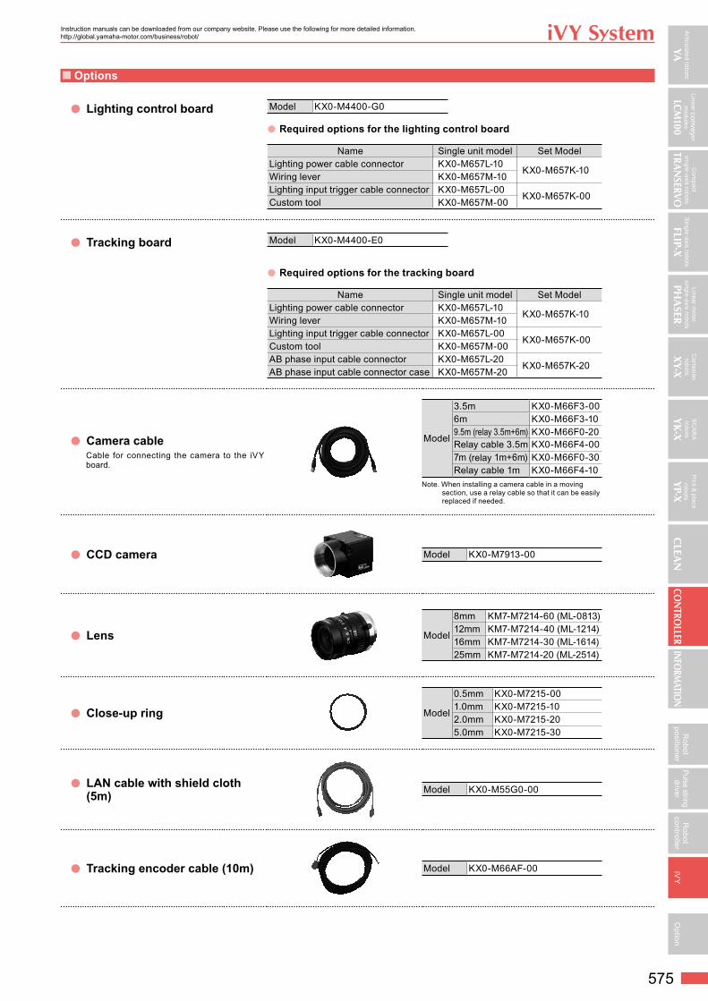
■ Options
● Lighting control board Model KX0-M4400-G0
● Required options for the lighting control board
Name Single unit model Set ModelLighting power cable connector KX0-M657L-10
KX0-M657K-10Wiring lever KX0-M657M-10Lighting input trigger cable connector KX0-M657L-00
KX0-M657K-00Custom tool KX0-M657M-00
● Tracking board Model KX0-M4400-E0
● Required options for the tracking board
Name Single unit model Set ModelLighting power cable connector KX0-M657L-10
KX0-M657K-10Wiring lever KX0-M657M-10Lighting input trigger cable connector KX0-M657L-00
KX0-M657K-00Custom tool KX0-M657M-00AB phase input cable connector KX0-M657L-20
KX0-M657K-20AB phase input cable connector case KX0-M657M-20
● Camera cableCable for connecting the camera to the iVY board.
Model
3.5m KX0-M66F3-006m KX0-M66F3-109.5m (relay 3.5m+6m) KX0-M66F0-20Relay cable 3.5m KX0-M66F4-007m (relay 1m+6m) KX0-M66F0-30Relay cable 1m KX0-M66F4-10
Note. When installing a camera cable in a moving section, use a relay cable so that it can be easily replaced if needed.
● CCD camera Model KX0-M7913-00
● Lens Model
8mm KM7-M7214-60 (ML-0813)12mm KM7-M7214-40 (ML-1214)16mm KM7-M7214-30 (ML-1614)25mm KM7-M7214-20 (ML-2514)
● Close-up ring Model
0.5mm KX0-M7215-001.0mm KX0-M7215-102.0mm KX0-M7215-205.0mm KX0-M7215-30
● LAN cable with shield cloth (5m)
Model KX0-M55G0-00
● Tracking encoder cable (10m) Model KX0-M66AF-00