Embed Size (px)
Citation preview
DOI : 10.23883/IJRTER.2017.3340.G4YAZ 428
Robotic Arm with Writing Skills
K. N. Paithankar1 , Prof. A. L. Borkar2
1Electronics & Telecommunication Engg,MSS’S College of Engineering & Technology, Jalna. 2Electronics & Telecommunication Engg,MSS’S College of Engineering & Technology, Jalna.
Abstract: Robotics is the interdisciplinary branch of engineering and science that includes
mechanical engineering, electrical engineering, computer science, and others. Robotics deals with
the design, construction, operation, and use of robots, as well as computer systems for their control,
sensory feedback, and information processing. Robotics is a key technology in the modern world.
Robots are a well-established part of manufacturing and warehouse automation, assembling cars or
washing machines, and, for example, moving goods to and from storage racks for Internet mail
order. More recently robots have taken their first steps into homes and hospitals, and seen
spectacular success in planetary exploration. Robotics is the branch of mechanical engineering,
electrical engineering and computer science that deals with the design, construction, operation, and
application of robots, as well as computer systems for their control, sensory feedback, and
information processing. These technologies deal with automated machines that can take the place
of humans in dangerous environments or manufacturing processes, or resemble humans in
appearance, behavior, and/or cognition. Robotics brings together several very different engineering
areas and skills. There is metalworking for the body. There is mechanics for mounting the wheels
on the axles, connecting them to the motors and keeping the body in balance. You need electronics
to power the motors and connect the sensors to the controllers. At last you need the software to
understand the sensors and drive the robot around. A robotic arm is a type of mechanical arm,
usually programmable, with similar functions to a human arm; the arm may be the sum total of the
mechanism or may be part of a more complex robot.
KEYWORDS: LPC 2148 Microcontroller, Mechanical assembly, SAPI, .NET Framework.
I. INTRODUCTION Robotics performs very important role in every field. Robotics brings together several very
different engineering areas and skills. There is metalworking for the body. There is mechanics for
mounting the wheels on the axles, connecting them to the motors and keeping the body in balance.
You need electronics to power the motors and connect the sensors to the controllers. At last you
need the software to understand the sensors and drive the robot around. Throughout history,
robotics has been often seen to mimic human behavior, and often manage tasks in a similar fashion.
Today, robotics is a rapidly growing field, as technological advances continue; researching,
designing, and building new robots serve various practical purposes, whether domestically,
commercially, or militarily. Many robots do jobs that are hazardous to people such as defusing
bombs, mines and exploring shipwrecks. Robotics can be described as the current pinnacle of
technical development. Robotics is a confluence science using the continuing advancements of
mechanical engineering, material science, sensor fabrication, manufacturing techniques, and
advanced algorithms.
The study and practice of robotics will expose a dabbler or professional to hundreds of different
avenues of study. For some, the romanticism of robotics brings forth an almost magical curiosity of
the world leading to creation of amazing machines. A journey of a lifetime awaits in robotics.
Robotics can be defined as the science or study of the technology primarily associated with the
design, fabrication, theory, and application of robots.
International Journal of Recent Trends in Engineering & Research (IJRTER) Volume 03, Issue 06; June - 2017 [ISSN: 2455-1457]
@IJRTER-2017, All Rights Reserved 429
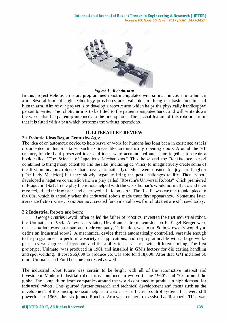
Figure 1. Robotic arm
In this project Robotic arms are programmed robot manipulator with similar functions of a human
arm. Several kind of high technology prostheses are available for doing the basic functions of
human arm. Aim of our project is to develop a robotic arm which helps the physically handicapped
person to write. The robotic arm is to be fitted to the patient's amputee hand, and will write down
the words that the patient pronounces to the microphone. The special feature of this robotic arm is
that it is fitted with a pen which performs the writing operations.
II. LITERATURE REVIEW
2.1 Robotic Ideas Began Centuries Ago:
The idea of an automatic device to help serve or work for humans has long been in existence as it is
documented in historic tales, such as ideas like automatically opening doors. Around the 9th
century, hundreds of preserved texts and ideas were accumulated and came together to create a
book called "The Science of Ingenious Mechanisms." This book and the Renaissance period
combined to bring many scientists and the like (including da Vinci) to imaginatively create some of
the first automatons (objects that move automatically). Most were created for joy and laughter
(The Lady Musician) but they slowly began to bring the past challenges to life. Then, robots
developed a negative connotation from a play called "Rossum's Universal Robots" which premiered
in Prague in 1921. In the play the robots helped with the work human's would normally do and then
revolted, killed their master, and destroyed all life on earth. The R.U.R. was written to take place in
the 60s, which is actually when the industrial robots made their first appearance. Sometime later,
a science fiction writer, Isaac Asimov, created fundamental laws for robots that are still used today.
2.2 Industrial Robots are born:
George Charles Devol, often called the father of robotics, invented the first industrial robot,
the Unimate, in 1954. A few years later, Devol and entrepreneur Joseph F. Engel Berger were
discussing interested at a part and their company, Unimation, was born. So how exactly would you
define an industrial robot? A mechanical device that is automatically controlled, versatile enough
to be programmed to perform a variety of applications, and re-programmable with a large works
pace, several degrees of freedom, and the ability to use an arm with different tooling. The first
prototype, Unimate, was produced in 1961 and installed in GM's factory for die casting handling
and spot welding. It cost $65,000 to produce yet was sold for $18,000. After that, GM installed 66
more Unimates and Ford became interested as well.
The industrial robot future was certain to be bright with all of the automotive interest and
investment. Modern industrial robot arms continued to evolve in the 1960's and 70's around the
globe. The competition from companies around the world continued to produce a high demand for
industrial robots. This spurred further research and technical development and items such as the
development of the microprocessor helped to create cost-effective control systems that were still
powerful. In 1963, the six-jointed Rancho Arm was created to assist handicapped. This was
International Journal of Recent Trends in Engineering & Research (IJRTER) Volume 03, Issue 06; June - 2017 [ISSN: 2455-1457]
@IJRTER-2017, All Rights Reserved 430
followed by the tentacle arm, designed by Marvin Minsky in 1968. It was able to lift a person and
had 12 joints. The first successful story of a business developing a specific robot based on their
needs was created in 1967. This company developed a robot to complete a spray painting
application and eventually became ABB. This is only one example of when large companies began
to develop their own industrial robots.
III. PROJECT DEVELOPMENT Robotic arms are programmed robot manipulator with similar functions of a human arm. Several
kind of high technology prostheses are available for doing the basic functions of human arm. Aim
of our project is to develop a robotic arm which helps the physically handicapped person to write.
The robotic arm is to be fitted to the patient's amputee hand, and will write down the words that the
patient pronounces to the microphone. The special feature of this robotic arm is that it is fitted with
a pen which performs the writing operations.
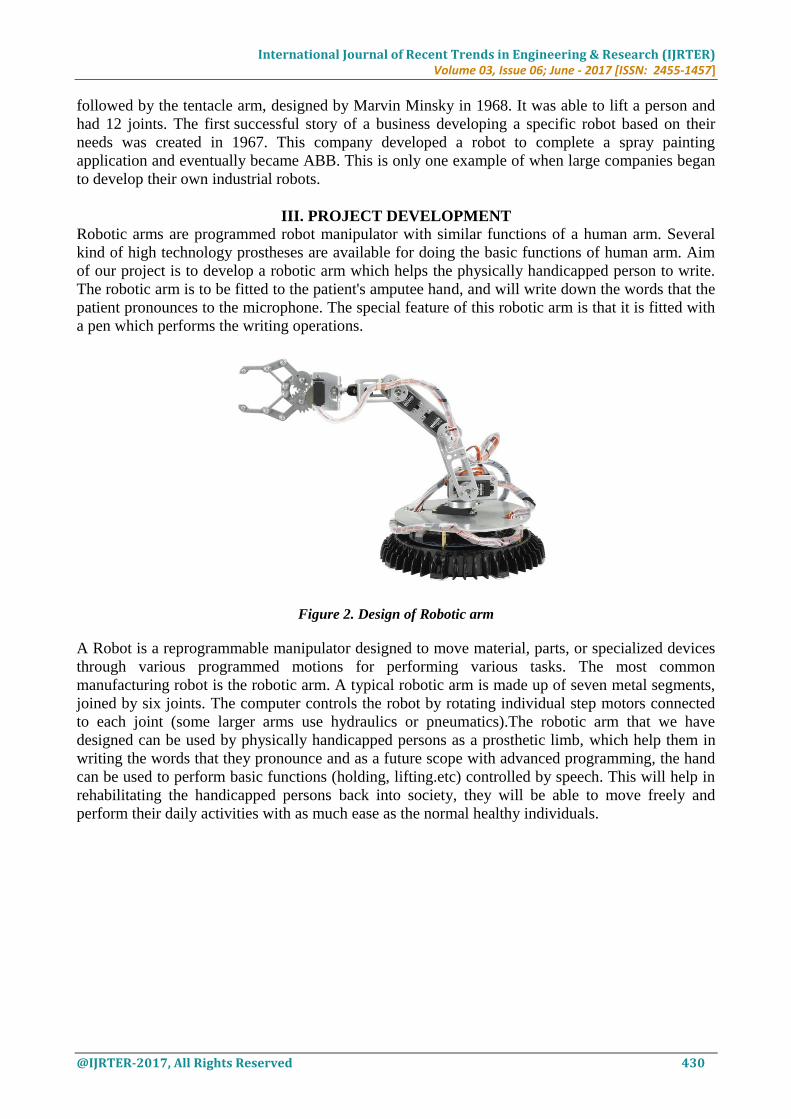
Figure 2. Design of Robotic arm
A Robot is a reprogrammable manipulator designed to move material, parts, or specialized devices
through various programmed motions for performing various tasks. The most common
manufacturing robot is the robotic arm. A typical robotic arm is made up of seven metal segments,
joined by six joints. The computer controls the robot by rotating individual step motors connected
to each joint (some larger arms use hydraulics or pneumatics).The robotic arm that we have
designed can be used by physically handicapped persons as a prosthetic limb, which help them in
writing the words that they pronounce and as a future scope with advanced programming, the hand
can be used to perform basic functions (holding, lifting.etc) controlled by speech. This will help in
rehabilitating the handicapped persons back into society, they will be able to move freely and
perform their daily activities with as much ease as the normal healthy individuals.
International Journal of Recent Trends in Engineering & Research (IJRTER) Volume 03, Issue 06; June - 2017 [ISSN: 2455-1457]
@IJRTER-2017, All Rights Reserved 431
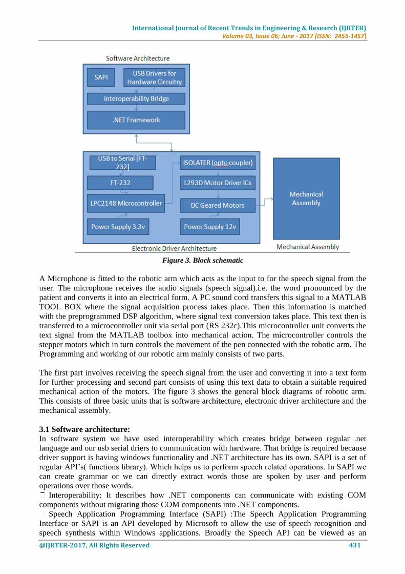
Figure 3. Block schematic
A Microphone is fitted to the robotic arm which acts as the input to for the speech signal from the
user. The microphone receives the audio signals (speech signal).i.e. the word pronounced by the
patient and converts it into an electrical form. A PC sound cord transfers this signal to a MATLAB
TOOL BOX where the signal acquisition process takes place. Then this information is matched
with the preprogrammed DSP algorithm, where signal text conversion takes place. This text then is
transferred to a microcontroller unit via serial port (RS 232c).This microcontroller unit converts the
text signal from the MATLAB toolbox into mechanical action. The microcontroller controls the
stepper motors which in turn controls the movement of the pen connected with the robotic arm. The
Programming and working of our robotic arm mainly consists of two parts.
The first part involves receiving the speech signal from the user and converting it into a text form
for further processing and second part consists of using this text data to obtain a suitable required
mechanical action of the motors. The figure 3 shows the general block diagrams of robotic arm.
This consists of three basic units that is software architecture, electronic driver architecture and the
mechanical assembly.
3.1 Software architecture: In software system we have used interoperability which creates bridge between regular .net
language and our usb serial driers to communication with hardware. That bridge is required because
driver support is having windows functionality and .NET architecture has its own. SAPI is a set of
regular API’s( functions library). Which helps us to perform speech related operations. In SAPI we
can create grammar or we can directly extract words those are spoken by user and perform
operations over those words.
Interoperability: It describes how .NET components can communicate with existing COM
components without migrating those COM components into .NET components.
Speech Application Programming Interface (SAPI) :The Speech Application Programming
Interface or SAPI is an API developed by Microsoft to allow the use of speech recognition and
speech synthesis within Windows applications. Broadly the Speech API can be viewed as an
International Journal of Recent Trends in Engineering & Research (IJRTER) Volume 03, Issue 06; June - 2017 [ISSN: 2455-1457]
@IJRTER-2017, All Rights Reserved 432
interface or piece of middleware which sits between applications and speech engines (recognition
and synthesis). In SAPI versions 1 to 4, applications could directly communicate with engines. The
API included an abstract interface definition which applications and engines conformed to.
Applications could also use simplified higher-level objects rather than directly call methods on the
engines.
.NET Framework: The Microsoft .Net Framework is a platform that provides tools and
technologies you need to build Networked Applications as well as Distributed Web Services and
Web Applications.
The .Net Framework provides the necessary compile time and run-time foundation to build and run
any language that conforms to the Common Language Specification (CLS).The main two
components of .Net Framework are Common Language Runtime (CLR) and .Net Framework Class
Library (FCL).The Common Language Runtime (CLR) is the runtime environment of the .Net
Framework, that executes and manages all running code like a Virtual Machine. The .Net
Framework Class Library (FCL) is a huge collection of language-independent and type-safe
reusable classes. The .Net Framework Class Libraries (FCL) is arranged into a logical grouping
according to their functionality and usability is called Namespaces.
3.2 Electronic driver architecture: We are supposed to use two DC geared motors to drive robotic arm in operating all directions and
maximum area (as above 1800).Two motors needs one L293D and to drive four we are using two
L293D. We are having 2 different types of power supplies one is of 3.3 volts for LPC2148 (ARM
Microcontroller) and another 12v. for Motor driver. L293D works similar to relay architecture. We
use DC Geared so that it performs each operation in a specific angle which helps us to calculate
degree and direction in proper manner. FT-232 is a USB to serial converter IC.
er:

International Journal of Recent Trends in Engineering & Research (IJRTER) Volume 03, Issue 06; June - 2017 [ISSN: 2455-1457]
@IJRTER-2017, All Rights Reserved 433
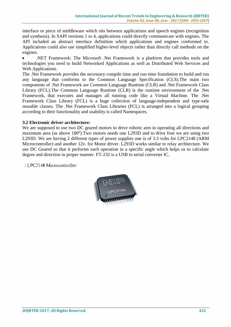
Figure 4. LPC2148Microcontroller
Figure 4 shows the pin diagram of LPC 2148 ARM 7 based Microcontroller. Over the last few
years, the ARM architecture has become the most pervasive 32-bitarchitecture in the world, with
wide range of ICs available from various IC manufacturers. ARM processors are embedded in
products ranging from cell/mobile phones to automotive braking systems. A worldwide community
of ARM partners and third-party vendors has developed among semiconductor and product design
companies, including hardware engineers, system designers, and software developers.ARM7 is one
of the widely used micro-controller family in embedded system application. This section is humble
effort for explaining basic features of ARM-7.
ARM is a family of instruction set architectures for computer processors based on a reduced
instruction set computing (RISC) architecture developed by British company ARM Holdings. A
RISC-based computer design approach means ARM processors require significantly fewer
transistors than typical processors in average computers. This approach reduces costs, heat and
power use.
These are desirable traits for light, portable, battery-powered devices—including smart phones,
laptops, tablet and notepad computers), and other embedded systems. A simpler design facilitates
more efficient multi-core CPUs and higher core counts at lower cost, providing higher processing
power and improved energy efficiency for servers and supercomputers.ARM7 LPC2148
Microcontroller Socket is used with LPC2148 Pro Development Board. It is a standalone board for
International Journal of Recent Trends in Engineering & Research (IJRTER) Volume 03, Issue 06; June - 2017 [ISSN: 2455-1457]
@IJRTER-2017, All Rights Reserved 434
LPC2148 microcontroller. It has 12MHz crystal for system clock and 32 KHz crystal for RTC. It
has power on reset circuit with MCP130T brownout monitoring chip and power decoupling
capacitors. This board can be used for LPC2148 based generic development. The heart of the
circuit is microcontroller, here we used LPC2148 ARM based Microcontroller.
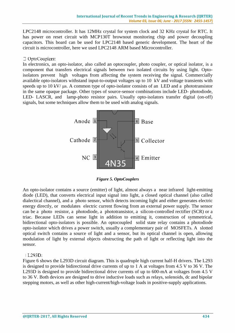
In electronics, an opto-isolator, also called an optocoupler, photo coupler, or optical isolator, is a
component that transfers electrical signals between two isolated circuits by using light. Opto-
isolators prevent high voltages from affecting the system receiving the signal. Commercially
available opto-isolators withstand input-to-output voltages up to 10 kV and voltage transients with
speeds up to 10 kV/ μs. A common type of opto-isolator consists of an LED and a phototransistor
in the same opaque package. Other types of source-sensor combinations include LED- photodiode,
LED- LASCR, and lamp-photo resistor pairs. Usually opto-isolators transfer digital (on-off)
signals, but some techniques allow them to be used with analog signals.
Figure 5. OptoCouplers
An opto-isolator contains a source (emitter) of light, almost always a near infrared light-emitting
diode (LED), that converts electrical input signal into light, a closed optical channel (also called
dialectical channel), and a photo sensor, which detects incoming light and either generates electric
energy directly, or modulates electric current flowing from an external power supply. The sensor
can be a photo resistor, a photodiode, a phototransistor, a silicon-controlled rectifier (SCR) or a
triac. Because LEDs can sense light in addition to emitting it, construction of symmetrical,
bidirectional opto-isolators is possible. An optocoupled solid state relay contains a photodiode
opto-isolator which drives a power switch, usually a complementary pair of MOSFETs. A slotted
optical switch contains a source of light and a sensor, but its optical channel is open, allowing
modulation of light by external objects obstructing the path of light or reflecting light into the
sensor.
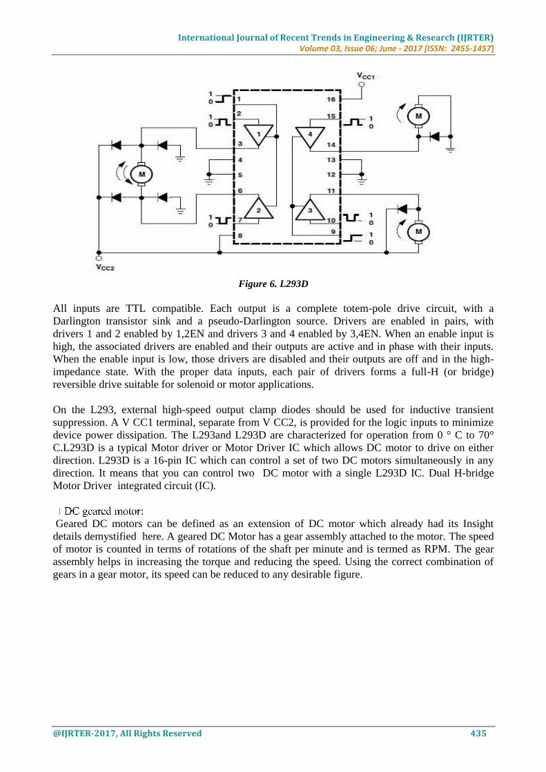
Figure 6 shows the L293D circuit diagram. This is quadruple high current half-H drivers. The L293
is designed to provide bidirectional drive currents of up to 1 A at voltages from 4.5 V to 36 V. The
L293D is designed to provide bidirectional drive currents of up to 600-mA at voltages from 4.5 V
to 36 V. Both devices are designed to drive inductive loads such as relays, solenoids, dc and bipolar
stepping motors, as well as other high-current/high-voltage loads in positive-supply applications.
International Journal of Recent Trends in Engineering & Research (IJRTER) Volume 03, Issue 06; June - 2017 [ISSN: 2455-1457]
@IJRTER-2017, All Rights Reserved 435
Figure 6. L293D
All inputs are TTL compatible. Each output is a complete totem-pole drive circuit, with a
Darlington transistor sink and a pseudo-Darlington source. Drivers are enabled in pairs, with
drivers 1 and 2 enabled by 1,2EN and drivers 3 and 4 enabled by 3,4EN. When an enable input is
high, the associated drivers are enabled and their outputs are active and in phase with their inputs.
When the enable input is low, those drivers are disabled and their outputs are off and in the high-
impedance state. With the proper data inputs, each pair of drivers forms a full-H (or bridge)
reversible drive suitable for solenoid or motor applications.
On the L293, external high-speed output clamp diodes should be used for inductive transient
suppression. A V CC1 terminal, separate from V CC2, is provided for the logic inputs to minimize
device power dissipation. The L293and L293D are characterized for operation from 0 ° C to 70°
C.L293D is a typical Motor driver or Motor Driver IC which allows DC motor to drive on either
direction. L293D is a 16-pin IC which can control a set of two DC motors simultaneously in any
direction. It means that you can control two DC motor with a single L293D IC. Dual H-bridge
Motor Driver integrated circuit (IC).
Geared DC motors can be defined as an extension of DC motor which already had its Insight
details demystified here. A geared DC Motor has a gear assembly attached to the motor. The speed
of motor is counted in terms of rotations of the shaft per minute and is termed as RPM. The gear
assembly helps in increasing the torque and reducing the speed. Using the correct combination of
gears in a gear motor, its speed can be reduced to any desirable figure.
International Journal of Recent Trends in Engineering & Research (IJRTER) Volume 03, Issue 06; June - 2017 [ISSN: 2455-1457]
@IJRTER-2017, All Rights Reserved 436
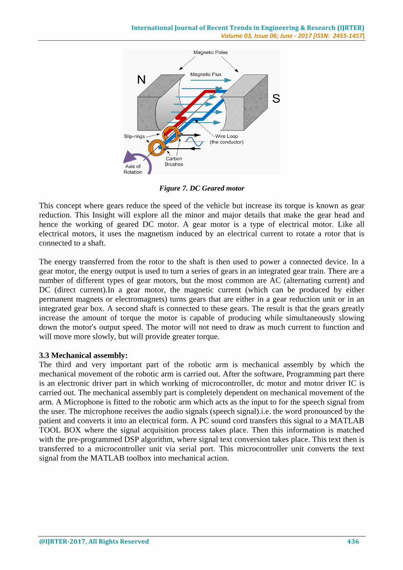
Figure 7. DC Geared motor
This concept where gears reduce the speed of the vehicle but increase its torque is known as gear
reduction. This Insight will explore all the minor and major details that make the gear head and
hence the working of geared DC motor. A gear motor is a type of electrical motor. Like all
electrical motors, it uses the magnetism induced by an electrical current to rotate a rotor that is
connected to a shaft.
The energy transferred from the rotor to the shaft is then used to power a connected device. In a
gear motor, the energy output is used to turn a series of gears in an integrated gear train. There are a
number of different types of gear motors, but the most common are AC (alternating current) and
DC (direct current).In a gear motor, the magnetic current (which can be produced by either
permanent magnets or electromagnets) turns gears that are either in a gear reduction unit or in an
integrated gear box. A second shaft is connected to these gears. The result is that the gears greatly
increase the amount of torque the motor is capable of producing while simultaneously slowing
down the motor's output speed. The motor will not need to draw as much current to function and
will move more slowly, but will provide greater torque.
3.3 Mechanical assembly: The third and very important part of the robotic arm is mechanical assembly by which the
mechanical movement of the robotic arm is carried out. After the software, Programming part there
is an electronic driver part in which working of microcontroller, dc motor and motor driver IC is
carried out. The mechanical assembly part is completely dependent on mechanical movement of the
arm. A Microphone is fitted to the robotic arm which acts as the input to for the speech signal from
the user. The microphone receives the audio signals (speech signal).i.e. the word pronounced by the
patient and converts it into an electrical form. A PC sound cord transfers this signal to a MATLAB
TOOL BOX where the signal acquisition process takes place. Then this information is matched
with the pre-programmed DSP algorithm, where signal text conversion takes place. This text then is
transferred to a microcontroller unit via serial port. This microcontroller unit converts the text
signal from the MATLAB toolbox into mechanical action.
International Journal of Recent Trends in Engineering & Research (IJRTER) Volume 03, Issue 06; June - 2017 [ISSN: 2455-1457]
@IJRTER-2017, All Rights Reserved 437
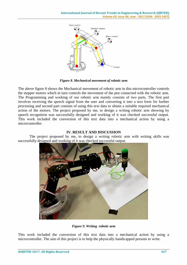
Figure 8. Mechanical movement of robotic arm
The above figure 8 shows the Mechanical movement of robotic arm in this microcontroller controls
the stepper motors which in turn controls the movement of the pen connected with the robotic arm.
The Programming and working of our robotic arm mainly consists of two parts. The first part
involves receiving the speech signal from the user and converting it into a text form for further
processing and second part consists of using this text data to obtain a suitable required mechanical
action of the motors. The project proposed by me, to design a writing robotic arm showing by
speech recognition was successfully designed and working of it was checked successful output.
This work included the conversion of this text data into a mechanical action by using a
microcontroller.
IV. RESULT AND DISCUSSION
The project proposed by me, to design a writing robotic arm with writing skills was
successfully designed and working of it was checked successful output.
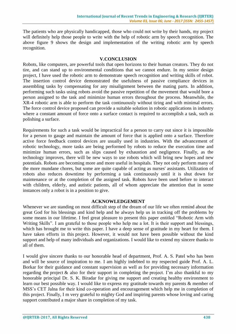
Figure 9. Writing robotic arm
This work included the conversion of this text data into a mechanical action by using a
microcontroller. The aim of this project is to help the physically handicapped persons to write.
International Journal of Recent Trends in Engineering & Research (IJRTER) Volume 03, Issue 06; June - 2017 [ISSN: 2455-1457]
@IJRTER-2017, All Rights Reserved 438
The patients who are physically handicapped, those who could not write by their hands, my project
will definitely help those people to write with the help of robotic arm by speech recognition. The
above figure 9 shows the design and implementation of the writing robotic arm by speech
recognition.
V.CONCLUSION Robots, like computers, are powerful tools that open horizons to their human creators. They do not
tire, and can stand up to environmental conditions that we cannot endure. In my senior design
project, I have used the robotic arm to demonstrate speech recognition and writing skills of robot.
The insertion control device demonstrated the usefulness of passive compliance devices in
assembling tasks by compensating for any misalignment between the mating parts. In addition,
performing such tasks using robots avoid the passive repetition of the movement that would bore a
person assigned to the task and minimize human errors throughout the process. Meanwhile, the
XR-4 robotic arm is able to perform the task continuously without tiring and with minimal errors.
The force control device proposed can provide a suitable solution in robotic applications in industry
where a constant amount of force onto a surface contact is required to accomplish a task, such as
polishing a surface.
Requirements for such a task would be impractical for a person to carry out since it is impossible
for a person to gauge and maintain the amount of force that is applied onto a surface. Therefore
active force feedback control devices are usually used in industries. With the advancement of
robotic technology, more tasks are being performed by robots to reduce the execution time and
minimize human errors, such as slips caused by exhaustion and negligence. Finally, as the
technology improves, there will be new ways to use robots which will bring new hopes and new
potentials. Robots are becoming more and more useful in hospitals. They not only perform many of
the more mundane chores, but some are quite capable of acting as nurses' assistants. Utilization of
robots also reduces downtime by performing a task continuously until it is shut down for
maintenance or at the completion of the assigned task. Robots have been used before to interact
with children, elderly, and autistic patients, all of whom appreciate the attention that in some
instances only a robot is in a position to give.
ACKNOWLEDGEMENT Whenever we are standing on most difficult step of the dream of our life we often remind about the
great God for his blessings and kind help and he always help us in tracking off the problems by
some means in our lifetime. I feel great pleasure to present this paper entitled “Robotic Arm with
Writing Skills”. I am grateful to those people who help me a lot. It is their support and blessings,
which has brought me to write this paper. I have a deep sense of gratitude in my heart for them. I
have taken efforts in this project. However, it would not have been possible without the kind
support and help of many individuals and organizations. I would like to extend my sincere thanks to
all of them.
I would give sincere thanks to our honorable head of department, Prof. A. S. Patel who has been
and will be source of inspiration to me. I am highly indebted to my respected guide Prof. A. L.
Borkar for their guidance and constant supervision as well as for providing necessary information
regarding the project & also for their support in completing the project. I’m also thankful to my
honorable principal Dr. S. K. Biradar for giving me support and creating healthy environment to
learn our best possible way. I would like to express my gratitude towards my parents & member of
MSS’s CET Jalna for their kind co-operation and encouragement which help me in completion of
this project. Finally, I m very grateful to mighty God and inspiring parents whose loving and caring
support contributed a major share in completion of my task.
International Journal of Recent Trends in Engineering & Research (IJRTER) Volume 03, Issue 06; June - 2017 [ISSN: 2455-1457]
@IJRTER-2017, All Rights Reserved 439
REFERENCES 1. Nocks, Lisa. The robot : the life story of a technology. Westport, CT: Greenwood Publishing Group. 2007
2. Zunt, Dominik. "Who did actually invent the word "robot" and what does it mean?". The Karel Capek website.
Retrieved 2007-09-11.
3. Asimov, Isaac . "The Robot Chronicles". Gold. London: Voyager. pp. 224–225. ISBN 0-00- 648202-3.1995-
1996.
4. Fowler, Charles B. "The Museum of Music: A History of Mechanical Instruments".Music Educators Journal
54(2): 4549. doi:10.2307/3391092
5. .JSTOR 3391092. October 1967.
6. McMorran, Darren; Chung, Dwayne Chung Kim; Li, Jonathan; Muradoglu, Murat; Liew, Oi Wah; Ng, Tuck Wah
(2016-02-16). "Adapting a Low-Cost Selective Compliant Articulated Robotic Arm for Spillage
Avoidance". Journal of Laboratory Automation: 2211068216630742. ISSN 2211-
0682. PMID 26882923. doi:10.1177/2211068216630742
7. Rosheim, Mark E. "Robot Evolution: The Development of Anthrobotics. " Wiley-IEEE. pp. 9– 10.ISBN 0-471-
02622-0.1994.
8. Billing, Rius; Fleischner, Richard. "Mars Science Laboratory Robotic Arm". 15th European Space Mechanisms
and Tribology Symposium 2011. Retrieved 2012-08-21.
9. T. N. Hornyak. "Loving the Machine: The Art and Science of Japanese Robots. " Kodansha International. 2006.
10. Assembleon."SMT pick-and-place equipment". Archived from the original on 2008-08-03. Retrieved 2008-09-21.
11. R.P. Lippmann. "Review of neural networks of speech recognition", Neural computation, v1 (1), pp 1-38, 1989
12. Ashraf Elfasakhany, Eduardo Yanez, Karen Baylon, Ricardo Salgado, "Design and Development of a Competitive
Low-Cost Robot Arm with Four Degrees of Freedom". Modern Mechanical Engineering, 1, November 2011,
47-55.2011.
13. Carvalho, Matheus C.; Eyre, Bradley D. (2013-12-01). "A low cost, easy to build, portable, and universal
autosampler for liquids". Methods in Oceanography. 8: 23–32. doi:10.1016/j.mio.2014.06.001