Embed Size (px)
Citation preview

1
Robotic Catheter Cardiac Ablation Combining Ultrasound Guidance and Force Control
Samuel B. Kesner and Robert D. Howe
Harvard School of Engineering and Applied Sciences, Cambridge, MA, USA skesner, [email protected]
Abstract Cardiac catheters allow physicians to access the inside of the heart and perform
therapeutic interventions without stopping the heart or opening the chest. However,
conventional manual and actuated cardiac catheters are currently unable to precisely track and
manipulate the intracardiac tissue structures because of the fast tissue motion and potential for
applying damaging forces. This paper addresses these challenges by proposing and
implementing a robotic catheter system that use 3D ultrasound image guidance and force control
to enable constant contact with a moving target surface in order to perform interventional
procedures, such as intracardiac tissue ablation. The robotic catheter system, consisting of a
catheter module, ablation and force sensing end effector, drive system, and image-guidance and
control system, was commanded to apply a constant force against a moving target using a
position-modulated force control method. The control system uses a combination of position
tracking, force feedback, and friction and backlash compensation to achieve accurate and safe
catheter-tissue interactions. The catheter was able to maintain a 1 N force on a moving motion
simulator target under ultrasound guidance with 0.08 N RMS error. In a simulated ablation
experiment, the robotic catheter was also able to apply a consistent force on the target while
maintaining ablation electrode contact with 97% less RMS contact resistance variation than a
passive mechanical equivalent. In addition, the use of force control improved catheter motion
tracking by approximately 20%. These results demonstrate that 3D ultrasound guidance and
force tracking allow the robotic system to maintain improved contact with a moving tissue
structure, thus allowing for more accurate and repeatable cardiac procedures.
1 Introduction
Advances in cardiac catheter technology allow physicians to treat a range of conditions
This work was supported by the U.S. National Institutes of Health under Grant NIH R01 HL073647
2
inside the beating heart while avoiding both the invasiveness of opening the chest and the
cognitive impairment risks associated with cardiopulmonary bypass (Baim 2005, 992; Murkin et al.
1999, 1498-1501; Roach et al. 1996, 1857-1864). However, the majority of catheters currently used
for cardiac interventions only allow for slow manual motions of the catheter tip and are unable to
control the forces applied to the tissue surfaces. Commercially available robotic catheter
systems, such as the Artisan Control Catheter (Hansen Medical, Mountain View CA, USA) or
the CorPath Vascular Robotic System (Corindus Vascular Robotics, Natick MA, USA), achieve
manual catheter manipulation speeds while allowing the operator to utilize robotic teleoperation
to reduce radiation exposure (Camarillo et al. 2008, 1262-1273; Beyar 2010, 207-213; Jayender,
Azizian, and Patel 2008, 858-871). However, neither the manual nor the commercial robotic
catheter systems are able to compensate for the fast cardiac motion or regulate the forces applied
to the tissue surface.
The goal of our work is to enable a robotic catheter to track the fast motions of the heart
while controlling the forces applied by the catheter end effector to the tissue in order to improve
the safety and efficacy of medical procedures. This objective is achieved through the use of 3D
ultrasound (3DUS) guidance, active motion compensation, and catheter tip force control. One
medical application that may benefit from this technology is the radiofrequency (RF) ablation of
cardiac tissue. Ablation is used by interventional cardiologists and cardiac surgeons to destroy
cardiac conduction pathways that contribute to arrhythmias, or heart beat abnormalities (Huang,
Huang, and Wilber 2000). The outcome success of this procedure is dependent on the electrode
contact with the tissue and force application, and therefore can benefit from the robotic system
proposed here (Okumura, Johnson, and Packer 2007, S318; Shah et al. 2010, 1038-1043; Shah et al.
2011, 277; Kalman et al. 1997, 8-18). In addition to cardiac ablation, other applications of this
robotic system include beating heart cardiac valve repair and replacement and the delivery of
implants to moving structures inside of the beating heart, such as septal defect repair implants.
In previous work, we have demonstrated in vivo the ability of the robotic catheter system
to compensate for the fast motion of the heart (Kesner and Howe 2011c, 1-11). In addition, a
custom catheter tip force sensor was developed to enable the catheter to maintain a constant
force against a target (Kesner and Howe 2012). However, the catheter force control system has to
date only been evaluated on the benchtop using noise-free simulated position signals rather than
noisy ultrasound image-derived signals (Kesner and Howe 2011a, 1-5; Kesner and Howe 2011b,

3
1589-1594). Other work in cardiac motion compensation has focused primarily on interacting
with the exterior of the beating heart (Ginhoux et al. 2005, 67-79; Bebek and Cavusoglu 2007, 468–
480; Nakamura, Kishi, and Kawakami 2001, 2014–2019; Richa, Bó, and Poignet 2010, 4579-4584). In
addition, the previous work in robotic catheters has primarily focused on teleoperation and
position control (Camarillo et al. 2008, 1262-1273; Beyar 2010, 207-213; Jayender, Azizian, and Patel
2008, 858-871). To the authors’ knowledge, the work presented here represents the first time
3DUS image guidance and force control has been used to enable a robotic catheter to accurately
interact with a moving target. As shown below, the combination of force feedback and 3DUS
servoing improves both the force and position control performance. Furthermore, this paper
presents the first steps towards applying the 3DUS-guided and motion compensated catheter
system to a clinical procedure, improving cardiac ablation using force control.
The following section presents the robotic catheter system, the force sensing and ablation
end effector, and the force control method. Next, the paper presents the evaluation of the system,
including benchtop experiments examining the control method, water tank evaluations of the
image guidance force controller, and experiments evaluating the efficacy of the robotic catheter
system during a simulated cardiac ablation as compared against a passive manual catheter.
Finally, this paper concludes with a discussion of the implications and limitations of the results
and future applications of the technology. This work demonstrates the potential benefits of
integrating motion-compensation and force control with cardiac intervention catheters.
Figure 1: The robotic system servos the catheter using 3DUS guidance and force feedback.
4
2 Technical Approach
The goal of the robotic catheter system is to use real-time 3DUS to measure the target
tissue motion and then drive the actuated catheter to synchronize with the motion and while
interacting with and repairing a cardiac target tissue. The catheter system is designed to rapidly
servo along one degree of freedom at speeds and displacements sufficient for tracking certain
cardiac structures including the human mitral valve annulus (Kesner and Howe 2011c, 1-11; Kettler
et al. 2007, 1290-1295). The system (Figure 1) is composed of three main modules: the drive
system that actuates the catheter, the catheter module that is inserted through the vasculature into
the heart, and the 3D ultrasound visual servoing system that tracks the tissue and commands the
catheter to follow the motion.
The catheter drive system (Figure 3.1) is composed of a linear voice coil actuator
(NCC20-18-02-1X, H2W Technologies Inc, Valencia CA; 50.8 mm travel, 26.7 N peak force), a
linear ball bearing slide (BX3-3, Tusk Direct, Inc., Bethel CT), and a linear potentiometer
position sensor (LP-50F, Midori America Corp, Fullerton CA, linearity: ±0.5%) that are able to
rapidly adjust the catheter position. The catheter module consists of a sheath, a guidewire, and
the end effectors required for each specific repair procedure. The sheath is an 85 cm long section
of flexible Teflon or Nylon tubing that encloses the guidewire, a close-wound stainless steel
spring that is easily bent but can apply significant compressive forces without buckling. During a
procedure, the sheath is inserted from a peripheral blood vessel into the heart and then fixed in
place while the drive system servos the guidewire inside the sheath to compensate for the heart
motion and regulate the forces applied to the cardiac tissue.
2.1 3D Ultrasound Servoing System
The visual servoing system utilizes a 3DUS machine (Figure 1, SONOS 7500 with X4
Ultrasound Transducer, Philips Healthcare, Andover, MA, USA) that streams volumes at 28 Hz
and a guidance system to track and predict the tissue motion in order to determine the real-time
position of the cardiac tissue and control the catheter (Novotny et al. 2007a, 458-464; Novotny et al.
2007b, 2655-2660; Yuen, Novotny, and Howe 2008, 3875-3880; Yuen et al. 2009, 1355).
5
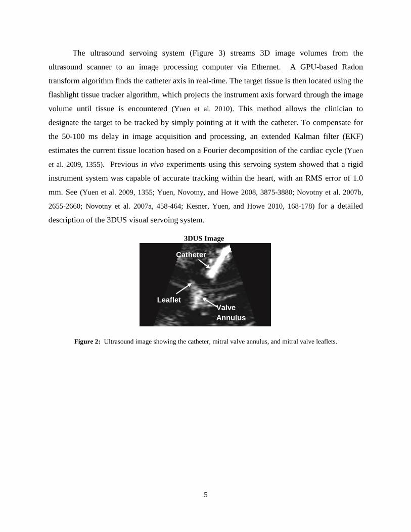
The ultrasound servoing system (Figure 3) streams 3D image volumes from the
ultrasound scanner to an image processing computer via Ethernet. A GPU-based Radon
transform algorithm finds the catheter axis in real-time. The target tissue is then located using the
flashlight tissue tracker algorithm, which projects the instrument axis forward through the image
volume until tissue is encountered (Yuen et al. 2010). This method allows the clinician to
designate the target to be tracked by simply pointing at it with the catheter. To compensate for
the 50-100 ms delay in image acquisition and processing, an extended Kalman filter (EKF)
estimates the current tissue location based on a Fourier decomposition of the cardiac cycle (Yuen
et al. 2009, 1355). Previous in vivo experiments using this servoing system showed that a rigid
instrument system was capable of accurate tracking within the heart, with an RMS error of 1.0
mm. See (Yuen et al. 2009, 1355; Yuen, Novotny, and Howe 2008, 3875-3880; Novotny et al. 2007b,
2655-2660; Novotny et al. 2007a, 458-464; Kesner, Yuen, and Howe 2010, 168-178) for a detailed
description of the 3DUS visual servoing system.
Figure 2: Ultrasound image showing the catheter, mitral valve annulus, and mitral valve leaflets.
Valve Annulus
Catheter
Leaflet
3DUS Image

6
Figure 3: The 3DUS servoing system uses 3D ultrasound imaging to automatically synchronize the motion of an
actuated device with a tissue target. The circled numbers indicate the order of data flow through the system: 1) The
time-delayed 3DUS images, 2) the tissue positions generated by the tissue tracking algorithm, 3) the delay-
compensated tissue positions, and 4) the resultant tracking position of the motion compensation catheter.
2.2 Force Sensor
In addition to the robotic catheter, a novel integrated force sensing and ablation end
effector is presented here for the first time (Figure 4). The design goal of the ablation tool is to
enable the catheter system to apply RF energy to the fast-moving tissue inside the heart while
applying a constant normal force. The functional requirements of the ablation end effector are to
sense forces, to ablate tissue using a clinical RF generator with a similar efficacy to conventional
ablation catheters, and to be robust enough to operate in the intracardiac environment. The
device consists of a force sensor described in (Kesner and Howe 2011a, 1-5), a stainless steel
electrode, and a fine wire that runs through the catheter body to connect the electrode to the
external RF current generator. The current prototype is approximately 5 mm in diameter and is
created using rapid prototyping 3D printing technology. The size of the end effector can be
further reduced with improved fabrication such as laser micromachining and metal laser
sintering. Figure 4b presents examples of the RF ablation lesions created with this tool on
porcine skeletal muscle tissue (RF generator: Stockert 70, Biosense Webster, Diamond Bar,
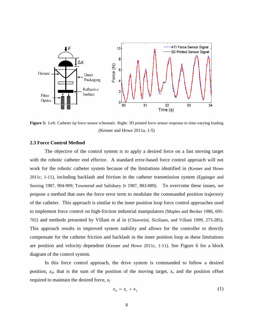
California, USA). Figure 5 presents a schematic diagram of the force sensor component of the

7
ablation end effector and example force sensor performance data. The force sensor converts
applied forces into small deflections of a reflective surface supported by flexures. The reflective
surface modulates the amount of light reflected back to a fiber optic sensor, which is calibrated
and used to determine the amount of applied force. NiTi wires flexures (0.25 mm diameter) are
arranged in a perpendicular configuration, which allows for large defections along the axis of the
catheter but resists lateral deflections, has little hysteresis, and prevents rubbing of the sensor
components. Superelastic NiTi flexures were selected for overload protection. A fiber optic
transducer was selected for this sensor because it is inexpensive, easy to implement, and requires
no electrical components within the catheter (Webster 1988). Integrating the transducer into the
sensor is as simple as inserting the fibers and fixing them in place with adhesive.
The Objet Connex500 3D printer (Objet Geometries Ltd, Billerica, MA, USA) was used
to fabricate the catheter ablation and force sensor end effector. This printer has a minimum
resolution of 16 microns and can print with a range of photopolymers, from a stiff acrylic plastic
to a rubber-like, flexible plastic (see (Objet Geometries Ltd. 2010)). For this work, the Verowhite
photopolymer was selected because it is a stiff plastic (2 GPa) with a high tensile strength (50
MPa).
The catheter tip sensor was calibrated and tested with a commercial 6-axis force torque
sensor (Mini40, ATI Industrial Automation, Apex, NC, USA). The 3D printed sensor was
manually loaded against the ATI sensor with a varying force profile. The signal from the fiber
optic sensor was amplified with a digital fiber amplifier (E3X-DA21-N, Omron Electronics LLC
Industrial Automation, Schaumburg, IL, USA) before digital acquisition (DAQCard-6024E,
National Instruments Corp., Austin TX, USA). See (Kesner and Howe 2011a, 1-5) for a more
detail description of the 3D printed force sensor technology.
Figure 4: a) Ablation end effector solid model and prototype. b) Tissue sample (porcine skeletal muscle) ablated
with the RF ablation end effector. Lesions are approximately 4 mm in diameter.
5mm
a b
8
Figure 5: Left: Catheter tip force sensor schematic. Right: 3D printed force sensor response to time-varying loading
(Kesner and Howe 2011a, 1-5)
2.3 Force Control Method
The objective of the control system is to apply a desired force on a fast moving target
with the robotic catheter end effector. A standard error-based force control approach will not
work for the robotic catheter system because of the limitations identified in (Kesner and Howe
2011c, 1-11), including backlash and friction in the catheter transmission system (Eppinger and
Seering 1987, 904-909; Townsend and Salisbury Jr 1987, 883-889). To overcome these issues, we
propose a method that uses the force error term to modulate the commanded position trajectory
of the catheter. This approach is similar to the inner position loop force control approaches used
to implement force control on high-friction industrial manipulators (Maples and Becker 1986, 695-
702) and methods presented by Villani et al in (Chiaverini, Siciliano, and Villani 1999, 273-285).
This approach results in improved system stability and allows for the controller to directly
compensate for the catheter friction and backlash in the inner position loop as these limitations
are position and velocity dependent (Kesner and Howe 2011c, 1-11). See Figure 6 for a block
diagram of the control system.
In this force control approach, the drive system is commanded to follow a desired
position, xd, that is the sum of the position of the moving target, xe and the position offset
required to maintain the desired force, xf
fed xxx += (1)

9
The force modulation term is
∫ −+−= dtFFKFFKx edfiedff )()( (2)
where Fd is desired force, Fe is the force applied to the environment, and Kf and Kfi are controller
gains. The drive system is commanded to follow the desired position trajectory with a standard
PID controller running at 1 kHz.
Figure 6: The force control system block diagram. The control system uses force and position feedback as well as
compensation terms to command the catheter to maintain a desired force on a moving target.
2.4 Compensation Methods
Compensation terms are introduced to the position feedback loop to improve the control
system performance, indicated in the block diagram in Figure 6 by dotted lines (Kesner and Howe
2011c, 1-11). Friction compensation assumes a Coulombic friction model for the catheter and
then feeds forward the friction force Ffc, based on an observer that predicts the velocity (Kesner
and Howe 2011c, 1-11). The friction force is determined during operation through an estimation
routine that utilizes the motor current values and is dominated by the catheter system design
(materials, geometry) and sheath configuration bend angle (θ). The bend angle (θ) can be
determined during a procedure using a number of methods, including bend sensors embedded
along the length of the catheter sheath (Prisco ), electromagnetic tracking (Wilson et al. 2008,
69182B-1), and the extraction of catheter bend angle information from medical images (most
likely X-ray fluoroscopy) during the procedure. Backlash compensation adds an additional term
10
to xd that adjusts the desired base position to overcome the deadzone behavior in the catheter
module. The amount of compensation, xdzc, is determined using a catheter-specific deadzone
model presented in (Kesner and Howe 2011c, 1-11):
)( gwshdzc DDx −=θ (3)
where Dsh is the inner diameter of the sheath and Dgw is the diameter of the guidewire. The
compensation term xdzc is either added or subtracted from xd based on the direction of target
motion and the position of the guidewire relative to the deadzone region. While the deadzone
value is sensitive to the bend angle, this parameter can be accurately measured with the methods
described above and will not vary greatly over the course of a procedure as the sheath is
constrained by the vasculature between the entry site and the heart.
2.5 Force Controller Limitations
The performance of the force control method described here is limited by a number of
factors, including the accuracy of the tissue motion tracking, the compensation terms, and the
unmodeled effects of the environment.
The most significant limitation of the controller is its dependence on accurate target
motion information for motion compensation and force regulation. The controller relies on the
periodic motion of the cardiac tissue to enable accurate predictive position estimations (Yuen,
Novotny, and Howe 2008, 3875-3880; Kesner and Howe 2011c, 1-11). If the tissue motion
deviates greatly from the previous periodic trajectory, the desired position (xd) component of the
position control loop will be incorrect because the estimated position of the environment (xe) will
not match the real tissue motion. Possible sources of target motion tracking errors include
external disturbances like arrhythmias or ectopic beats, unmodeled motions like respirations,
changes in the tissue motion due to the forces applied by the catheter, and failures of the motion
prediction algorithm to converge on the correct trajectory due to poor imaging quality or tool
positioning (Yuen et al. 2008; Yuen et al. 2009, 1355; Kesner and Howe 2011c, 1-11).
Another limitation of the force controller arises from changes to the physical catheter
system. The controller assumes a static model for the system performance parameters for a
given catheter configuration. For example, the friction forces and backlash parameters are fixed

11
for each catheter position and orientation. While assuming a static catheter configuration is
reasonable while operating in the constrained workspace inside the heart, other factors, such as
blood clots developing between the catheter guidewire and sheath, can change the friction and
backlash model parameters. To overcome these model limitations, the backlash and friction are
determined once the catheter is in position but before it has engaged the tissue to include any
effects from recent changes in the system or configuration.
In certain situations, the model-predicted deadzone width must be increased to account
for the deformation of the sheath and guidewire caused by significant catheter friction (Kesner
and Howe 2011c, 1-11). In this study, xdzc was doubled for certain trials to account for the
increased deadzone width caused by significant friction values as high as 2 N. This friction-
dependant backlash behavior has been reported in previous work (Kesner and Howe 2010, 1059-
1065; Kesner and Howe 2011c, 1-11).
Figure 7: Benchtop evaluation experimental setup
3 Benchtop Experimental Evaluation
The force control methods proposed above were first evaluated on the benchtop to
characterize the system and determine how well the catheter can maintain a desired force against
a fast moving target. Based on our previous studies of fast motion compensating with a catheter,
the important experimental variables to examine are the catheter bend angle (θ) and the speed
and trajectory of the target (Kesner and Howe 2011c, 1-11). See Figure 7 for a diagram of the
benchtop experimental setup used to evaluate the controller designs. Ground truth values were
determined using a number of appropriate sensing modalities, including electromagnetic trackers
12
(3D Guidance trakSTAR system, Ascension Technology Corporation, Milton VT, USA) to
measure the catheter tip trajectory, a linear potentiometer position sensor integrated into the
motion simulator mechanism to sense the target position, and a commercial force sensor (LCFD-
1KG, Omega Engineering, Stamford, CT, USA; range: 10 N, accuracy: +/-0.015 N) and the
catheter force sensor to determine the applied force values.
The first set of experiments examined the performance of the force control schemes while
interacting with a target following a 12 mm peak-to-peak, 1 Hz sinusoidal trajectory in three
sheath bend configurations: 0°, 180°, and 360°. The friction, modeled as simple Coulombic
friction, increases approximately linearly with bend angle (Kesner and Howe 2010, 1059-1065).
The width of the backlash deadzone, described in eqn. (3), is also a function of the bend angle
and can be accurately predicted with the deadzone width model first presented in (Kesner and
Howe 2010, 1059-1065).
A sinusoidal trajectory was selected as an initial experimental evaluation trajectory
because it is the dominant component of cardiac motion, as demonstrated by the spectral
decomposition in (Kettler et al. 2007, 1290-1295). For a more realistic experiments, a human
mitral valve annulus trajectory was also used below to evaluate the system (Kettler et al. 2007,
1290-1295).
To evaluate the performance of the proposed force control methods, the system was
tested with three controller configurations: 1) the force-modulated position controller in eqn. (2),
2) the controller with an added friction compensation term, and 3) the controller with both
friction and deadzone compensation terms. The force-modulation gains, Kf and Kfi, were tuned
for best stable performance and kept constant for all of the experiments.
3.1 Force control methods comparison
Figure 8 presents a comparison of the controller performance applying a constant force
(1 N) against the motion simulator target with the catheter in a 360° bend configuration. The
target was covered with a compliant foam with a stiffness (Ke) of approximately 0.25 N/mm to
simulate cardiac tissue.
The results in Figure 8 demonstrate that both friction and deadzone compensation greatly
improve the force tracking. Significant tracking errors can be seen when the target changes
direction in both Figure 8b and Figure 8c. These errors are because the controllers in these plots
13
do not compensate for the deadzone region behavior. Experimentally, this behavior appears as if
the tip of the catheter is delayed in responding to the changes in the target trajectory. Deadzone
compensation, demonstrated in Figure 8d, significantly improves the tracking by adjusting the
desired position to remove the backlash effects of the deadzone. Friction compensation also
improves tracking by cancelling the friction resistance in the sheath, as seen in the improvement
in performance between Figure 8b and Figure 8c.
Figure 9 summarizes the performance results of the three force controllers for each of the
three catheter configurations. The average performance of each the controllers, presented in
Figure 9a as the RMS deviation from the desired force, shows that the compensation terms
significantly improve the catheter system’s force tracking ability. For example, the RMS error
for the 360° bend configuration decreases by over 45% when friction compensated was added
and by almost 86% when both friction and deadzone compensated were added.
The maximum deviations from the desired force are expressed as the peak-to-peak value,
the difference between the maximum and minimum tip force value during each experiment.
These deviations are often greatest during the changes in the target’s direction of motion (Figure
8). This data, presented in Figure 9b, clearly indicates that the compensation methods reduce the
deviations from the desired force. For example, friction and backlash compensation decreased
the peak-to-peak variations in the 360° bend configuration by almost 60%. It should be noted
that for the 0° catheter bend configuration, the deadzone compensation does not alter the RMS or
peak-to-peak values because the catheter system has no deadzone according to the backlash
model in eqn. (3).
The effect of the frequency of the sinusoidal target was also investigated in this study.
The target frequency was varied from 0.1 – 1.6 Hz, approximately the range of possible heart
rates encountered during clinical procedures (6-96 BPM). The catheter was constrained in a 180°
bend configuration and the control system was commanded to maintain a desired force of 1 N
with and without friction and deadzone compensation.
14
Figure 8: Sinusoid trajectory comparison. (a) 1 Hz sinusoidal target trajectory and (b) the catheter tip force with
only force-modulated position control, (c) with the addition of friction compensation, and (d) with the addition of
both friction and deadzone compensation. The bend angle is 360°.
The results of these experiments are summarized in Figure 10. The RMS error for both
controllers was approximately constant across the frequency range, with the compensated
controller performing roughly 75% better than the uncompensated controller for all of the
frequencies. The peak-to-peak error increased as a function of the frequency. This trend is
because, as the frequency increases, the speed at which the catheter must travel through the
deadzone to maintain the desired force also increases.

15
Figure 9: (a) Force tracking RMS error and (b) force tracking peak-to-peak error against a 1 Hz sinusoidal target as
a function of bend angle for the three force control methods
Figure 10: (a) Force tracking RMS error and (b) peak-to-peak error while tracking a sinusoidal trajectory as a
function of the target frequency.
16
4 3D Ultrasound-Guided Performance Evaluation
The force controlled catheter system was also evaluated in water tank studies under
3DUS guidance. A water tank is required to evaluate the visual servoing system because clinical
ultrasound machines cannot operate in air.
4.1 Engaging the Target
One of the challenges of regulating the forces applied by the catheter tip to a target is the
transition from operating in free space to applying the desired force on the fast-moving target.
The process of engaging a surface is challenging because of the potential for the catheter tip to
apply large and destabilizing interaction forces. Furthermore, the catheter must be able to safely
retract from the target surface after the experiment is completed. To ensure that the catheter
contacts the target in a controlled manner, a trapezoidal position trajectory is commanded to
dictate the processes by which the tool engages and retracts from the target.
It is assumed that the catheter must maintain a constant force against the tissue in order to
apply a surgical technique such as ablate, resect, or staple the tissue. In the method used here,
the catheter approaches the surface at a rate of 2.5-5 mm/s, applies the desired force for 5 s, and
then retracts from the tissue at 5 mm/s. Figure 12 demonstrates engaging a static target. An
alternative engagement process is for the user to manually adjust the catheter position until it
Figure 11: Engaging the target: The catheter engages and retracts from a static target using a trapezoidal trajectory
to achieve the desired force.

17
makes first contact with the moving tissue and then switch to a force control method to maintain
a constant interaction force.
The process of engaging a target is further complicated when the target is quickly
moving, such as the mitral valve annulus (Kettler et al. 2007, 1290-1295). If the approach
process does not consider the motion of the target and progresses at a constant velocity, the
catheter tip may collide with the target surface and result in a large spike of force and possibly
system instability. To prevent this issue, the moving target is virtually stabilized relative to the
catheter tip by utilizing motion compensation during the approach procedure.
To prevent damage to the tissue or tool caused by instability or unexpected forces applied
to the catheter tip, the controller is instructed to pull back the catheter and enter a “safe mode” if
a larger than expected force is sensed at the tip. As demonstrated in Figure 13, the catheter
withdraws at a speed of 50 mm/s when a force spike is recorded at the tip. This force spike,
created by quickly hitting the tip of the catheter force sensor, simulates an ectopic heart beat not
anticipated by the motion compensation controller, causing the catheter tip to collide with the
heart wall. The force threshold, in this case 1.5 N, determines if the controller needs to pull back
the catheter into the safe mode.
In previous research we recorded forces required for interventional cardiac procedures up
to 1.5 N (Wagner et al. 2006, 43-48). We therefore selected 1 N as the target force level, with the
1.5 N level as the upper bound. Based on the literature, this target force is likely greater than the
Figure 13: The catheter tip immediately pulls back into a safe position if the force threshold (1.5 N) is exceeded
to prevent tissue damage.

18
optimal contact force for cardiac ablation (Shah et al. 2010, 1038-1043). The 1.5 N force
threshold was also selected during preliminary experiments to indicate that the force tracking had
diverged and to prevent any damage to the force sensor or catheter mechanisms.
Other possible metrics for determining this error state in addition to a force threshold
include a catheter velocity threshold to anticipate instability or limit cycles and a system power
function that includes both catheter tip velocity and force. In addition, electrocardiogram (ECG)
monitoring can be used to anticipate ectopic heart beats or arrhythmias and withdraw the catheter
to a safe position.
4.2 Evaluation Results
The catheter system was evaluated using the 3DUS tracking system in a water tank
interacting with both the sinusoidal and mitral valve annulus motion target. The use of the
3DUS complicates the force tracking process because of the importance of the target position
prediction, as discussed above in section 2.1. Even in the controlled environment of the water
tank experiment, the system performance varied between each trial due to the quality of the EKF
tissue position prediction component of the visual servoing system described in Section 2.1
(Yuen et al. 2010). In spite of these limitations, performance values of 0.08 N RMS errors were
achieved for the sinusoidal trajectory (Figure 14 ). Without friction and deadzone compensation,
force tracking results of only 0.15 N RMS were achieved relative to the sinusoidal target (Figure
14 ). Force control performance values of 0.17 N RMS errors were achieved while interacting
with a mitral valve annulus motion simulator with friction and deadzone compensation (Figure
15). The target trajectory for this experiment was generated from human mitral valve annulus
data (Kettler et al. 2007, 1290-1295). See Figure 14 and Figure 15 for plots of the system
performance in these experiments.

19
4.3 Motion tracking improvements due to force feedback
In addition to providing force tracking, the catheter control system also improves the
position tracking accuracy of the catheter tip. The position trajectory commanded by the 3DUS
tracking algorithm follows the true position of the human mitral valve motion simulator with
1.60 mm RMS error. However with the addition of the force feedback controller, the catheter
position is accurate to 1.31 mm, an improvement of almost 20%. Figure 16 illustrates this
improvement. The catheter trajectory tracks the minima and maxima of the target motion better
with the addition of the force feedback modulation controller.
No Compensation (Error = 0.15 N RMS) With Compensation (Error = 0.08 N RMS)
Figure 14: The force tracking results in a water tank under 3DUS guidance for the sinusoidal target trajectory. Left:
Without deadzone or friction compensation (RMS error = 0.15 N). Right: With compensation terms (RMS error =
0.08 N).
Figure 15: The force tracking results in a water tank under 3DUS guidance with a mitral valve annulus trajectory
target with the compensation terms. Force tracking error = 0.17 N RMS.

20
There are two possible explanations for this improved result. First, the backlash
compensation method commands the catheter to overshoot the target position at the extremes of
the motion trajectory. This behavior would provide improved motion tracking if the 3DUS
guidance method was not able to track the extremes of the target motion. The more likely
explanation is that the force feedback pushed and pulled the catheter into the correct positions.
As the catheter tip maintains contact with the target, any deviations of the position tracking will
result in an increase or decrease of the forces experienced at the catheter tip. The force feedback
loop responds to this force change by modulating the catheter tip position and adjusting the
catheter trajectory to better match the target. Thus, the force feedback modulation corrects some
of the errors of the 3DUS tracking by correcting its position to maintain the constant force on the
moving target.
Figure 16: The position-modulation term of the force controller improves the tip trajectory tracking. The three
lines are the actual target position, the desired catheter position determined by the force control system, and the
EKF-predicted target position from the 3DUS-guidance system.
5 Ablation Experiments
The final set of experiments presented here evaluates the robotic catheter system’s ability
to perform a simulated interventional task, maintaining ablation electrode contact against a
moving surface while applying a constant force. A number of studies have demonstrated that
cardiac ablation efficacy is directly related to the forces applied by the catheter tip and the
quality of the electrode-tissue contact (Okumura, Johnson, and Packer 2007, S318; Shah et al. 2010,
1038-1043; Shah et al. 2011, 277; Kalman et al. 1997, 8-18). Manually operated catheters do not
adequately ablate tissue if they are bouncing or sliding on the tissue surface, in poor contact due
21
to low forces, or creating tissue perforations due to large contact forces (Shah et al. 2011, 277;
Shah et al. 2010, 1038-1043). The objective of this evaluation was to demonstrate that the robotic
catheter system can maintain good target tissue contact and accurately control the applied force
in a simulated ablation task. Other representative evaluation tasks that could have also been
selected to examine the catheter system include placement of cardiac implants and manipulation
of cardiac valve structures (Kesner and Howe 2011c, 1-11; Yuen et al. 2008).
5.1 Evaluation Method
The system was evaluated by commanding the catheter to maintain a constant contact
force against a moving target. The target was composed of a conductive pad used as the current
return path electrode in clinical ablation and electrocautery procedures (REM Polyhesive II
Patient Return Electrode, Tyco Healthcare, Gosport, UK) backed with compliant foam
(thickness: 25 mm, approximate stiffness: 0.1 N/mm). The target was translated along a 12 mm
amplitude at a frequency of approximately 1 Hz (60 beats per minute). Two motion patterns
were tested: a sinusoidal trajectory and a human mitral annulus trajectory (Kettler et al. 2007,
1290-1295). The ablation quality was approximated by measuring the electrical resistance
between the catheter tip electrode and the return electrode pad using an instrumented voltage
divider designed to match the approximate resistance range of the catheter tip-target interaction
(Figure 17). For the purposes of these validation experiments, resistance also provides an
independent measure of contact quality that does not rely on ultrasound imaging. No ablation
energy was applied during the electrical resistance measurements. The water tank environment
was used to allow the 3DUS guidance system to visualize the catheter and target.
The evaluation experiment was conducted using both the robotic catheter and a
commercial manual ablation catheter (RF Marinr MCXL, Medtronic, Minneapolis, Minnesota,
USA) for comparison. A manual catheter was select as a passive mechanical equivalent to act as
a baseline for comparison in order to analyze the performance of the robotic catheter. For the
manual catheter, a load cell was also added to the target to record the forces applied by the
catheter tip (LCFD-1KG, Omega Engineering, Stamford, CT, USA; range: 10 N, accuracy: +/-
0.015 N). The robotic catheter was instrumented with the force-sensing ablation end effector
and was operated under force control with 3DUS guidance. Both catheters were rigidly braced
100 mm from the ablation tip at orientations perpendicular to the plane of the moving target.
22
The manual catheter was positioned so its ablation electrode was able to remain in contact during
the entire target trajectory (Figure 18). It should be noted that this experimental setup does not
accurately simulate all aspects of intracardiac ablation, including the compliance of the vessels in
the heart, the instrument orientation relative to the moving tissue structures, and the electrical
impedances of the cardiac environments and human body.
To measure the resistance, 5 V DC was applied to the patient return electrode and a
voltage divider was created at the proximal end of the catheters to measure the ablation
resistance (Figure 17). As the contact between the catheter and the target changed due to
variations of the contact force or tip position, the resistance between the catheter electrode and
the return electrode pad also changed. This resistance, Rabl, can be calculated from the resulting
output of the voltage divider, Vout:
Ω−Ω×= kkV
VRout
abl 10105 Ω×
−= k
VVout
1015 (4)
Figure 17: The catheter ablation experimental setup. The moving target was connected to a 5 V DC signal and the
catheters were instrumented with a voltage divider to measure the contact resistance. Resistance measurements
were used to evaluate tip contact quality for both a manual catheter and the robotic catheter system.

23
Manual Catheter Robotic Catheter
Figure 18: The water tank setup for the manual catheter (top) and the robotic catheter (bottom). Both images show
the catheters, the white 3DUS imaging probe, and the motion target.
5.2 Results
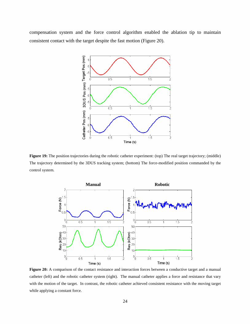
Figure 19 presents the position trajectories of the 3DUS tracking system, robotic catheter,
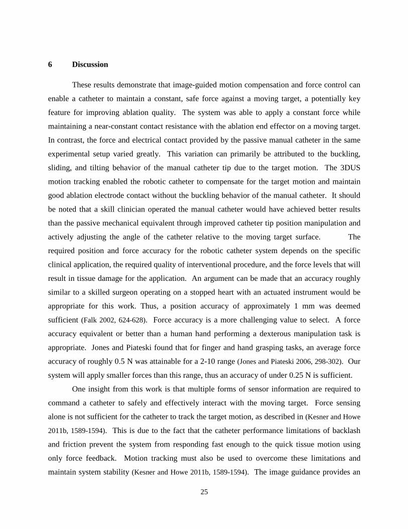
and motion simulator during the experiments. Figure 20 presents typical results of the ablation
experiment on the sinusoidal motion target. Both the manual and robotic catheters were in
contact with the moving target for over 5 s during each trial.
The manual catheter was not able to apply a constant force or maintain a constant
resistance. The reason for the manual catheter’s poor performance was because the motion of
the target caused the manual catheter ablation tip to slide and tilt relative to the target surface as
the motion simulator pushed on the catheter and caused it to buckle. Compliance is a desirable
feature in manual catheters because it prevents them from applying large forces and perforating
cardiac tissue. In addition, compliance also allows the catheter to remain in contact despite large
motion of cardiac structures. However, this bending compliance makes it challenging to achieve
reliable ablation performance. As shown in Figure 20, the manual catheter generated peak-to-
peak resistance variations of over 20 kOhm and peak-to-peak force variations of over 0.45 N,
approximately 125% of the mean force value (0.37 N).
The robotic catheter, in contrast to the manual catheter, achieved almost constant
resistance values while maintaining a desired force of 1 N with a force tracking error of
0.11 N RMS. The RMS variation of the resistance value for the robotic catheter was 0.25
kOhms, 97% less than the RMS variation of 9.88 kOhm for the manual catheter system. The
robotic catheter was able to achieve this level of performance because the 3DUS-guided motion
US Probe
Catheter
Target US Probe
Catheter
Target
24
compensation system and the force control algorithm enabled the ablation tip to maintain
consistent contact with the target despite the fast motion (Figure 20).
Figure 19: The position trajectories during the robotic catheter experiment: (top) The real target trajectory; (middle)
The trajectory determined by the 3DUS tracking system; (bottom) The force-modified position commanded by the
control system.
Manual Robotic
Figure 20: A comparison of the contact resistance and interaction forces between a conductive target and a manual
catheter (left) and the robotic catheter system (right). The manual catheter applies a force and resistance that vary
with the motion of the target. In contrast, the robotic catheter achieved consistent resistance with the moving target
while applying a constant force.
25
6 Discussion
These results demonstrate that image-guided motion compensation and force control can
enable a catheter to maintain a constant, safe force against a moving target, a potentially key
feature for improving ablation quality. The system was able to apply a constant force while
maintaining a near-constant contact resistance with the ablation end effector on a moving target.
In contrast, the force and electrical contact provided by the passive manual catheter in the same
experimental setup varied greatly. This variation can primarily be attributed to the buckling,
sliding, and tilting behavior of the manual catheter tip due to the target motion. The 3DUS
motion tracking enabled the robotic catheter to compensate for the target motion and maintain
good ablation electrode contact without the buckling behavior of the manual catheter. It should
be noted that a skill clinician operated the manual catheter would have achieved better results
than the passive mechanical equivalent through improved catheter tip position manipulation and
actively adjusting the angle of the catheter relative to the moving target surface. The
required position and force accuracy for the robotic catheter system depends on the specific
clinical application, the required quality of interventional procedure, and the force levels that will
result in tissue damage for the application. An argument can be made that an accuracy roughly
similar to a skilled surgeon operating on a stopped heart with an actuated instrument would be
appropriate for this work. Thus, a position accuracy of approximately 1 mm was deemed
sufficient (Falk 2002, 624-628). Force accuracy is a more challenging value to select. A force
accuracy equivalent or better than a human hand performing a dexterous manipulation task is
appropriate. Jones and Piateski found that for finger and hand grasping tasks, an average force
accuracy of roughly 0.5 N was attainable for a 2-10 range (Jones and Piateski 2006, 298-302). Our
system will apply smaller forces than this range, thus an accuracy of under 0.25 N is sufficient.
One insight from this work is that multiple forms of sensor information are required to
command a catheter to safely and effectively interact with the moving target. Force sensing
alone is not sufficient for the catheter to track the target motion, as described in (Kesner and Howe
2011b, 1589-1594). This is due to the fact that the catheter performance limitations of backlash
and friction prevent the system from responding fast enough to the quick tissue motion using
only force feedback. Motion tracking must also be used to overcome these limitations and
maintain system stability (Kesner and Howe 2011b, 1589-1594). The image guidance provides an
26
approximation of the desired position trajectory for the tip of the catheter and the force feedback
introduces minor adjustments to the tip position to regulate and maintain the tool-tissue
interactions forces. This insight is demonstrated with the 20% position tracking improvements
provided by the combination of the force control system and 3DUS motion tracking while
following the mitral valve annulus motion simulator, as shown in Figure 16Error! Reference
source not found.. Without either 3DUS guidance or force sensing, the catheter would be unable
to maintain the consistent ablation electrode contact and could either penetrate or retract from the
target surface.
In addition to 3DUS, other position tracking systems are available for intracardiac
interventions. For example, ablation impedance tracking systems, such as the CARTO system
(Biosense Webster, Inc., Diamond Bar, CA, USA), use a combination of the ablation catheter
position from electromagnetic tracking and the electrical impedance values to perform cardiac
mapping and ablation procedures. While these systems do assist clinicians to guide ablation
procedures, they do not track the physical position of the moving cardiac tissue in real time to
allow a catheter to compensate for the motion or apply a constant force against moving cardiac
structures. 3DUS enables the advantages of imaging and tracking both the catheter and soft
tissue to allow for safe manipulation of fast-moving cardiac tissues.
Although the experimental results demonstrate that the robotic catheter system is able to
apply a constant force while maintaining a consistent ablation contact, there are a number of
limitations in this initial validation study due to the challenges of accurately simulating in vivo
cardiac ablation in a laboratory setting. First, measuring the DC resistance of the contact does
not consider the electrical frequency response of the cardiac tissue at the 500 kHz frequency used
by the RF energy generator. In addition, the system was tested in water instead of electrically-
conductive blood or saline, which alters the electrode conduction properties. Finally, the
experimental setup did not approximate the exact mechanics of intracardiac ablation, including
the compliance of the vessels in the heart and the tool orientation relative to the moving tissue
structures. The manual catheter performance depends on its orientation with respect to the
moving tissue target, although similar fluctuations in force and resistance would have resulted
for other orientations. We anticipate that these issues will not impair the demonstrated
advantages of the robotic system because of the known properties of the ablation process and the

27
success of previous in vivo tests of the image guidance systems (Kesner and Howe 2011c, 1-11;
Yuen et al. 2008; Kesner, Yuen, and Howe 2010, 168-178).
7 Conclusions
This paper presents the experimental evaluation of a robotic catheter system for
interacting with the beating heart. The specific medical application selected for this system is
performing tissue ablation on a moving cardiac structure. The system uses motion compensation
and force feedback to maintain a constant force and contact resistance on a moving target. The
experimental results presented here demonstrated that the robotic system is able to apply a
constant force on a moving target with 0.08 N RMS error. In addition to accurately controlling
the catheter-tissue interaction forces, the system is able to maintain consistent ablation electrode
contact against a translating motion simulator with a 97% reduction in RMS resistance variation
over a passive and rigidly fixed manual catheter. This ablation result can be explained by the
fact that a compliant manual catheter slides and buckles while in contact with a quickly moving
structure, such as the actively contracting heart wall, while the robotic catheter actively
compensates for the motion and regulates the interaction forces. Finally, the combination of
force feedback and 3DUS guidance improves the trajectory tracking accuracy by adjusting the
catheter motion due to the forces experienced at the catheter tip while interacting with the
moving target.
Future work in this project will focus on the demonstration and evaluation of the
technology in an in vivo setting. While the motion compensation and robotic catheter system has
been demonstrated previously in vivo (Yuen et al. 2008; Kesner, Yuen, and Howe 2010, 168-178;
Kesner and Howe 2011c, 1-11), the force control ablation system has not yet been tested inside a
beating heart. One possible challenge the system will encounter in vivo is how to respond as the
tissue stiffness changes over the course of the heart cycle. In addition, safety issues such as
system stability and preventing tissue collisions will need to be further investigated. The project
objective is to enable a range of beating heart surgical procedures with a catheter, and the
ablation application explored here is a first step toward this ultimate goal.
28
References
Baim, Donald S., ed. 2005. Grossman's Cardiac Catheterization, Angiography, and Intervention. Philadelphia, PA: Lippincott Williams & Wilkins.
Bebek, O. and M. Cavusoglu. 2007. "Intelligent Control Algorithms for Robotic Assisted Beating Heart Surgery." IEEE Trans. on Robotics 23 (3): 468–480.
Beyar, R. 2010. "Navigation within the Heart and Vessels in Clinical Practice." Annals of the New York Academy of Sciences 1188 (1): 207-213.
Camarillo, D. B., C. F. Milne, C. R. Carlson, M. R. Zinn, and J. K. Salisbury. 2008. "Mechanics Modeling of Tendon-Driven Continuum Manipulators." Robotics, IEEE Transactions On 24 (6): 1262-1273.
Chiaverini, S., B. Siciliano, and L. Villani. 1999. "A Survey of Robot Interaction Control Schemes with Experimental Comparison." Mechatronics, IEEE/ASME Transactions On 4 (3): 273-285.
Eppinger, S. and W. Seering. 1987. "Understanding Bandwidth Limitations in Robot Force Control."IEEE, .
Falk, Volkmar. 2002. "Manual Control and Tracking—a Human Factor Analysis Relevant for Beating Heart Surgery." The Annals of Thoracic Surgery 74 (2): 624-628.
Ginhoux, R., J. Gangloff, M. de Mathelin, L. Soler, M. M. A. Sanchez, and J. Marescaux. 2005. "Active Filtering of Physiological Motion in Robotized Surgery using Predictive Control." Robotics, IEEE Transactions On 21 (1): 67-79.
Huang, S. K., S. K. S. Huang, and D. J. Wilber. 2000. Radiofrequency Catheter Ablation of Cardiac Arrhythmias: Basic Concepts and Clinical Applications Wiley-Blackwell.
Jayender, J., M. Azizian, and R. V. Patel. 2008. "Autonomous Image-Guided Robot-Assisted Active Catheter Insertion." Robotics, IEEE Transactions On 24 (4): 858-871.
Jones, Lynette A. and Erin Piateski. 2006. "Contribution of Tactile Feedback from the Hand to the Perception of Force." Experimental Brain Research 168 (1): 298-302.
Kalman, J. M., A. P. Fitzpatrick, J. E. Olgin, M. C. Chin, R. J. Lee, M. M. Scheinman, and M. D. Lesh. 1997. "Biophysical Characteristics of Radiofrequency Lesion Formation in Vivo: Dynamics of Catheter Tip-Tissue Contact Evaluated by Intracardiac Echocardiography." American Heart Journal 133 (1): 8-18.
Kesner, S. B., S. Yuen, and R. Howe. 2010. "Ultrasound Servoing of Catheters for Beating Heart Valve Repair." Information Processing in Computer-Assisted Interventions: 168-178.
Kesner, S. B. and R. D. Howe. 2010. "Design and Control of Motion Compensation Cardiac Catheters."IEEE, .

29
———. 2011a. "Design Principles for Rapid Prototyping Forces Sensors using 3-D Printing." Mechatronics, IEEE/ASME Transactions On (99): 1-5.
———. 2011b. "Force Control of Flexible Catheter Robots for Beating Heart Surgery."IEEE, .
———. 2012. "Motion Compensated Catheter Ablation of the Beating Heart using Image Guidance and Force Control." Quebec City, Canada, .
———. 2011c. "Position Control of Motion Compensation Cardiac Catheters." Robotics, IEEE Transactions On (99): 1-11.
Kettler, D. T., R. D. Plowes, P. M. Novotny, N. V. Vasilyev, P. J. del Nido, and R. D. Howe. 2007. "An Active Motion Compensation Instrument for Beating Heart Mitral Valve Surgery.".
Maples, J. and J. Becker. 1986. "Experiments in Force Control of Robotic Manipulators."IEEE, .
Murkin, J. M., W. D. Boyd, S. Ganapathy, S. J. Adams, and R. C. Peterson. 1999. "Beating Heart Surgery: Why Expect Less Central Nervous System Morbidity?" The Annals of Thoracic Surgery 68 (4): 1498-1501.
Nakamura, Y., K. Kishi, and H. Kawakami. 2001. "Heartbeat Synchronization for Robotic Cardiac Surgery.".
Novotny, P. M., J. A. Stoll, N. V. Vasilyev, P. J. Del Nido, P. E. Dupont, T. E. Zickler, and R. D. Howe. 2007a. "GPU Based Real-Time Instrument Tracking with Three-Dimensional Ultrasound." Medical Image Analysis 11 (5): 458-464.
Novotny, P. M., J. A. Stoll, P. E. Dupont, and R. D. Howe. 2007b. "Real-Time Visual Servoing of a Robot using Three-Dimensional Ultrasound.".
Objet Geometries Ltd. "FullCure870 VeroBlack Data Sheet." Objet Geometries Ltd2010.
Okumura, Y., S. Johnson, and D. Packer. 2007. "An Analysis of Catheter Tip/Tissue Contact Force-Induced Distortion of Three-Dimensional Electroanatomical Mapping Created using the Sensei Robotic Catheter System." Heart Rhythm 4: S318.
Prisco, G. M. Fiber Optic Shape Sensing.
Richa, R., A. P. L. Bó, and P. Poignet. 2010. "Beating Heart Motion Prediction for Robust Visual Tracking."IEEE, .
Roach, G. W., M. Kanchuger, C. M. Mangano, M. Newman, N. Nussmeier, R. Wolman, A. Aggarwal, K. Marschall, S. H. Graham, and C. Ley. 1996. "Adverse Cerebral Outcomes After Coronary Bypass Surgery." New England Journal of Medicine 335 (25): 1857-1864.
Shah, D., H. Lambert, A. Langenkamp, Y. Vanenkov, G. Leo, P. Gentil-Baron, and B. Walpoth. 2011. "Catheter Tip Force Required for Mechanical Perforation of Porcine Cardiac Chambers." Europace 13 (2): 277.

30
Shah, D. C., H. Lambert, H. Nakagawa, A. Langenkamp, N. Aeby, and G. Leo. 2010. "Area Under the Real‐Time Contact Force Curve (Force–Time Integral) Predicts Radiofrequency Lesion Size in an in Vitro Contractile Model." Journal of Cardiovascular Electrophysiology 21 (9): 1038-1043.
Townsend, W. and J. Salisbury Jr. 1987. "The Effect of Coulomb Friction and Stiction on Force Control."IEEE, .
Wagner, Christopher R., Douglas P. Perrin, Robert D. Howe, Nikolay Vasilyev, and Pedro J. Del Nido. 2006. "Force Feedback in a Three-Dimensional Ultrasound-Guided Surgical Task."IEEE, .
Webster, J. G. 1988. Tactile Sensors for Robotics and and Medicine. New York: John Wiley & Sons, Inc.
Wilson, E., Z. Yaniv, D. Lindisch, and K. Cleary. 2008. "A Buyer’s Guide to Electromagnetic Tracking Systems for Clinical Applications.".
Yuen, S. G., D. T. Kettler, P. M. Novotny, R. D. Plowes, and R. D. Howe. 2009. "Robotic Motion Compensation for Beating Heart Intracardiac Surgery." The International Journal of Robotics Research 28 (10): 1355.
———. 2010. "Robotic Tissue Tracking for Beating Heart Mitral Valve Surgery." Medical Image Analysis.
Yuen, S. G., S. B. Kesner, Nikolay V. Vasilyev, P. J. del Nido, and R. D. Howe. 2008. "3D Ultrasound-Guided Motion Compensation System for Beating Heart Mitral Valve Repair.".
———. 2008. "Quasiperiodic Predictive Filtering for Robot-Assisted Beating Heart Surgery.".