Embed Size (px)
Citation preview
Robotic Platform 1kg2008 (Fall)Motor Controller Timing Research
Motor Controller Timing ResearchProject Title: Robotic Platform for 1kg Loads (RP1)
Project Team: P09204
Project Revision: 2
Document Author: Jason Jack
1 of 12
Robotic Platform 1kg2008 (Fall)Motor Controller Timing Research
Table of Contents1 Research..............................................................................................................................................3
1.1 Overview......................................................................................................................................3
1.2 Stepper Motor.............................................................................................................................3
1.2.1 General Information............................................................................................................3
1.2.2 Unipolar...............................................................................................................................4
1.2.3 Bipolar..................................................................................................................................5
1.2.4 Universal Timing Circuitry....................................................................................................6
1.2.5 Rudimentary Controller Design............................................................................................8
1.3 DC Servo....................................................................................................................................10
1.4 DC Brushed Motor.....................................................................................................................11
2 Acronyms...........................................................................................................................................11
3 Document References.......................................................................................................................11
Table of FiguresFigure 1 - Stepper Motor Cutsection...........................................................................................................4Figure 2 - Unipolar Timing Diagram.............................................................................................................4Figure 3 - Bipolar Timing Diagram...............................................................................................................5Figure 4 - Full Step Bipolar Timing Diagram.................................................................................................6Figure 5 - Unipolar Timing Table..................................................................................................................6Figure 6 - H-Bridge Design...........................................................................................................................7Figure 7 - Bipolar Timing Table....................................................................................................................8Figure 8 - Log Book Stepper Motor Preliminary Design...............................................................................9Figure 9 - SSC-32 System Schematics.........................................................................................................10Figure 10 - Table of Acronyms...................................................................................................................11Figure 11 - Table of References.................................................................................................................12
2 of 12
Robotic Platform 1kg2008 (Fall)Motor Controller Timing Research
1 Research
1.1 OverviewThe Robotic Platform for 1kg Loads requires a series of motors to control rudimentary motion of the robotic platform. For details on movement control, user interface to the platform, and desired capabilities please reference the Interface Control Document (ICD) listed in the references section below.
There are a number of options for motor selection which should be considered before committing to a single design or set of parts. The first concern in motor selection is of course the specifications and capabilities of the motor itself. This portion of research is not mentioned in this document and should be performed separately. The second concern, and the focus of this research, is the timing and control circuitry associated with various types of motors. In the following sections, three types of motor controllers are explored and basic, preliminary designs are presented for various types of motors. The three motor controller design propositions are based around the Bipolar or Unipolar Stepper Motor, the DC Servo Motor, and the DC Brushed Motor controlled by PWM, respectively.
1.2 Stepper Motor
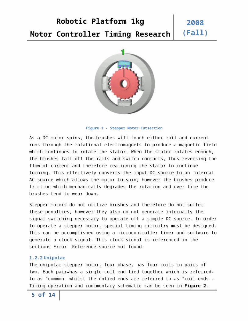
1.2.1 General InformationThe stepper motor is a brushless electric motor which can “break down” rotation into discrete “steps”. The stepper motor accomplishes this by using inductor coils and a toothed stator to control rotation. An image displaying a cut-section of a stepper motor with four coils is displayed in Figure 1 as taken from Wikipedia. Reference to the article this image was taken from is in section below. This compares to the DC motor operation which utilizes stationary permanent magnets and rotating electromagnets whose connections to VCC and GND are brushes to these power rails.
3 of 12

Robotic Platform 1kg2008 (Fall)Motor Controller Timing Research
Figure 1 - Stepper Motor Cutsection
As a DC motor spins, the brushes will touch either rail and current runs through the rotational electromagnets to produce a magnetic field which continues to rotate the stator. When the stator rotates enough, the brushes fall off the rails and switch contacts, thus reversing the flow of current and therefore realigning the stator to continue turning. This effectively converts the input DC source to an internal AC source which allows the motor to spin; however the brushes produce friction which mechanically degrades the rotation and over time the brushes tend to wear down.
Stepper motors do not utilize brushes and therefore do not suffer these penalties, however they also do not generate internally the signal switching necessary to operate off a simple DC source. In order to operate a stepper motor, special timing circuitry must be designed. This can be accomplished using a microcontroller timer and software to generate a clock signal. This clock signal is referenced in the sections Error: Reference source not found.
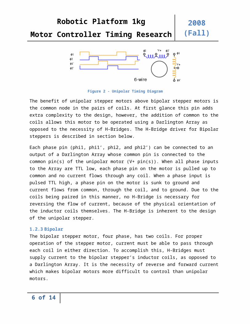
1.2.2 UnipolarThe unipolar stepper motor, four phase, has four coils in pairs of two. Each pair has a single coil end tied together which is referred to as “common” whilst the untied ends are referred to as “coil-ends”. Timing operation and rudimentary schematic can be seen in Figure 2.
Figure 2 - Unipolar Timing Diagram
4 of 12
Robotic Platform 1kg2008 (Fall)Motor Controller Timing Research
The benefit of unipolar stepper motors above bipolar stepper motors is the common node in the pairs of coils. At first glance this pin adds extra complexity to the design, however, the addition of common to the coils allows this motor to be operated using a Darlington Array as opposed to the necessity of H-Bridges. The H-Bridge driver for Bipolar steppers is described in section below.
Each phase pin (phi1, phi1’, phi2, and phi2’) can be connected to an output of a Darlington Array whose common pin is connected to the common pin(s) of the unipolar motor (V+ pin(s)). When all phase inputs to the Array are TTL low, each phase pin on the motor is pulled up to common and no current flows through any coil. When a phase input is pulsed TTL high, a phase pin on the motor is sunk to ground and current flows from common, through the coil, and to ground. Due to the coils being paired in this manner, no H-Bridge is necessary for reversing the flow of current, because of the physical orientation of the inductor coils themselves. The H-Bridge is inherent to the design of the unipolar stepper.
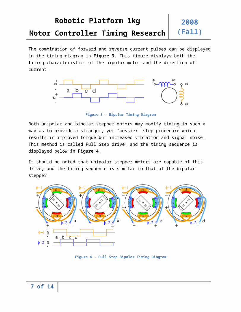
1.2.3 BipolarThe bipolar stepper motor, four phase, has two coils. For proper operation of the stepper motor, current must be able to pass through each coil in either direction. To accomplish this, H-Bridges must supply current to the bipolar stepper’s inductor coils, as opposed to a Darlington Array. It is the necessity of reverse and forward current which makes bipolar motors more difficult to control than unipolar motors.
The combination of forward and reverse current pulses can be displayed in the timing diagram in Figure 3. This figure displays both the timing characteristics of the bipolar motor and the direction of current.
Figure 3 - Bipolar Timing Diagram
Both unipolar and bipolar stepper motors may modify timing in such a way as to provide a stronger, yet “messier” step procedure which results in improved torque but increased vibration and signal noise. This method is called Full Step drive, and the timing sequence is displayed below in Figure 4.
It should be noted that unipolar stepper motors are capable of this drive, and the timing sequence is similar to that of the bipolar stepper.
5 of 12
Robotic Platform 1kg2008 (Fall)Motor Controller Timing Research
Figure 4 - Full Step Bipolar Timing Diagram
All figures displaying timing sequences in the Unipolar and Bipolar sections are taken from the Stepper Motor Basics online tutorial as listed in section below.
1.2.4 Universal Timing CircuitryThe bipolar and unipolar stepper motors share common timing signals when abstracted from their driver circuitry, be it either Darlington Arrays or H-Bridge circuitry. This is explained below.
To achieve universal timing circuitry, the key operating difference between the unipolar and bipolar stepper motors should be discussed. The key difference between the unipolar and bipolar stepper motors is the lack of the common node in the bipolar stepper, which results in the necessity of forward and reverse currents. To effectively reverse this dependence, a circuit should be designed to abstract this dependence on bi-directional current.
To begin, we analyze the timing required to operate a unipolar stepper motor. The state transition truth table is displayed in Figure 5.
Phi1 Phi2 Phi1’ Phi2’ Next Phi1 Next Phi2 Next Phi1’ Next Phi2’1 0 0 0 0 1 0 00 1 0 0 0 0 1 00 0 1 0 0 0 0 10 0 0 1 1 0 0 0
Figure 5 - Unipolar Timing Table
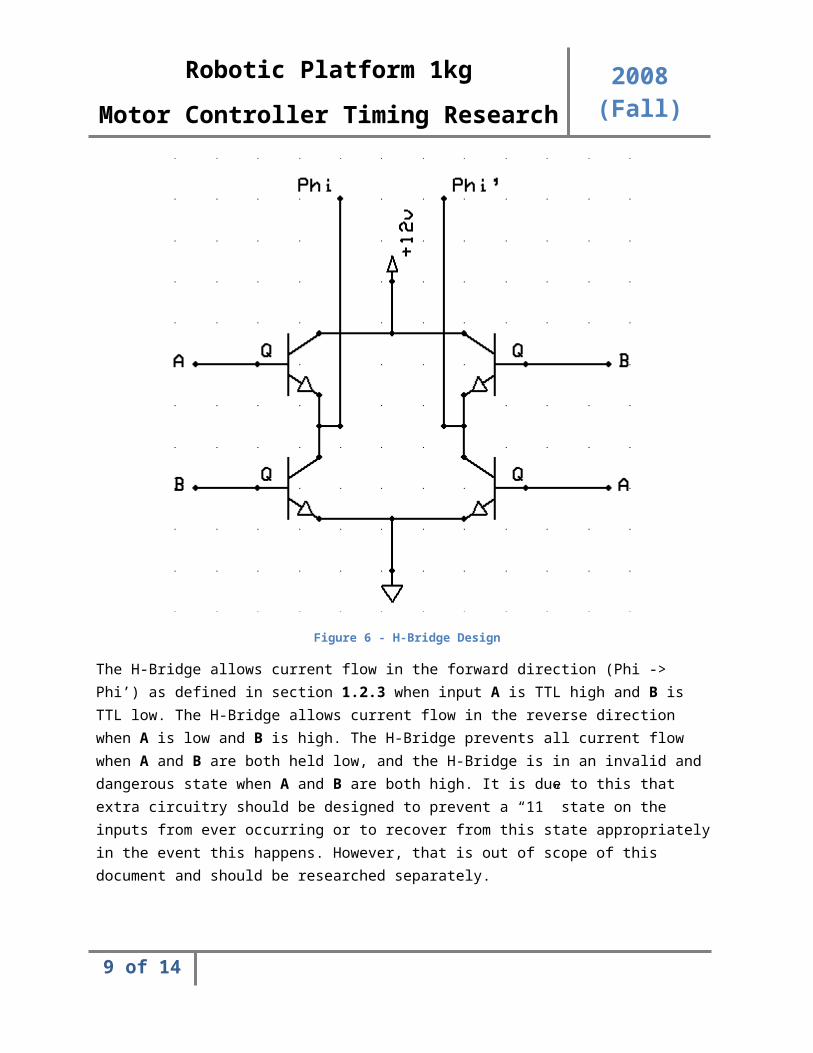
To analyze the timing for the bipolar stepper motor we have to first observe the H-Bridge which wraps each stepper coil. The basic schematic for an H-Bridge can be seen in Figure 6.
6 of 12
Robotic Platform 1kg
2008 (Fall)Motor Controller Timing Research
Figure 6 - H-Bridge Design
The H-Bridge allows current flow in the forward direction (Phi -> Phi’) as defined in section 1.2.3 when input A is TTL high and B is TTL low. The H-Bridge allows current flow in the reverse direction when A is low and B is high. The H-Bridge prevents all current flow when A and B are both held low, and the H-Bridge is in an invalid and dangerous state when A and B are both high. It is due to this that extra circuitry should be designed to prevent a “11” state on the inputs from ever occurring or to recover from this state appropriately in the event this happens. However, that is out of scope of this document and should be researched separately.
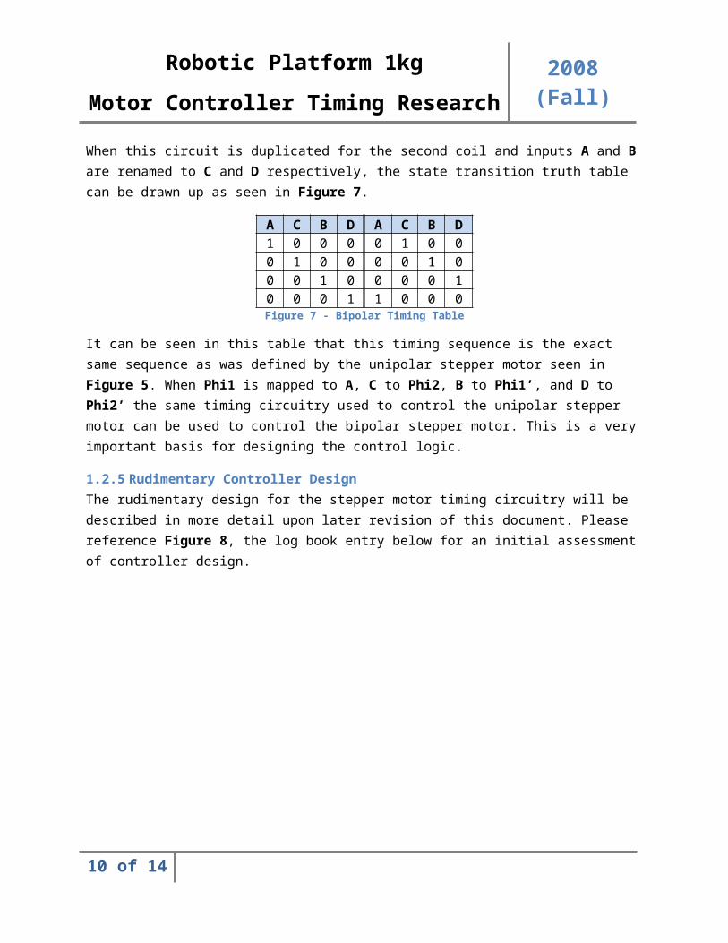
When this circuit is duplicated for the second coil and inputs A and B are renamed to C and D respectively, the state transition truth table can be drawn up as seen in Figure 7.
A C B D A C B D1 0 0 0 0 1 0 00 1 0 0 0 0 1 00 0 1 0 0 0 0 10 0 0 1 1 0 0 0
Figure 7 - Bipolar Timing Table
7 of 12

Robotic Platform 1kg
2008 (Fall)Motor Controller Timing Research
It can be seen in this table that this timing sequence is the exact same sequence as was defined by the unipolar stepper motor seen in Figure 5. When Phi1 is mapped to A, C to Phi2, B to Phi1’, and D to Phi2’ the same timing circuitry used to control the unipolar stepper motor can be used to control the bipolar stepper motor. This is a very important basis for designing the control logic.
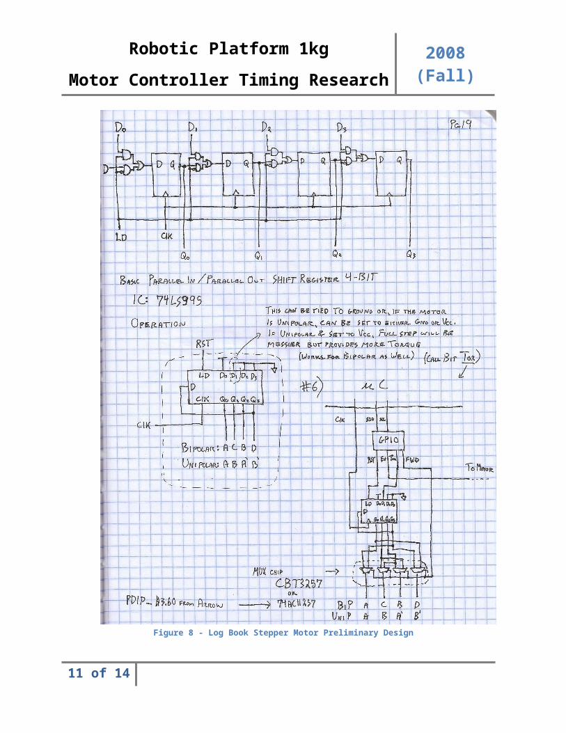
1.2.5 Rudimentary Controller DesignThe rudimentary design for the stepper motor timing circuitry will be described in more detail upon later revision of this document. Please reference Figure 8, the log book entry below for an initial assessment of controller design.
8 of 12
Robotic Platform 1kg
2008 (Fall)Motor Controller Timing Research
Figure 8 - Log Book Stepper Motor Preliminary Design
9 of 12
Robotic Platform 1kg
2008 (Fall)Motor Controller Timing Research
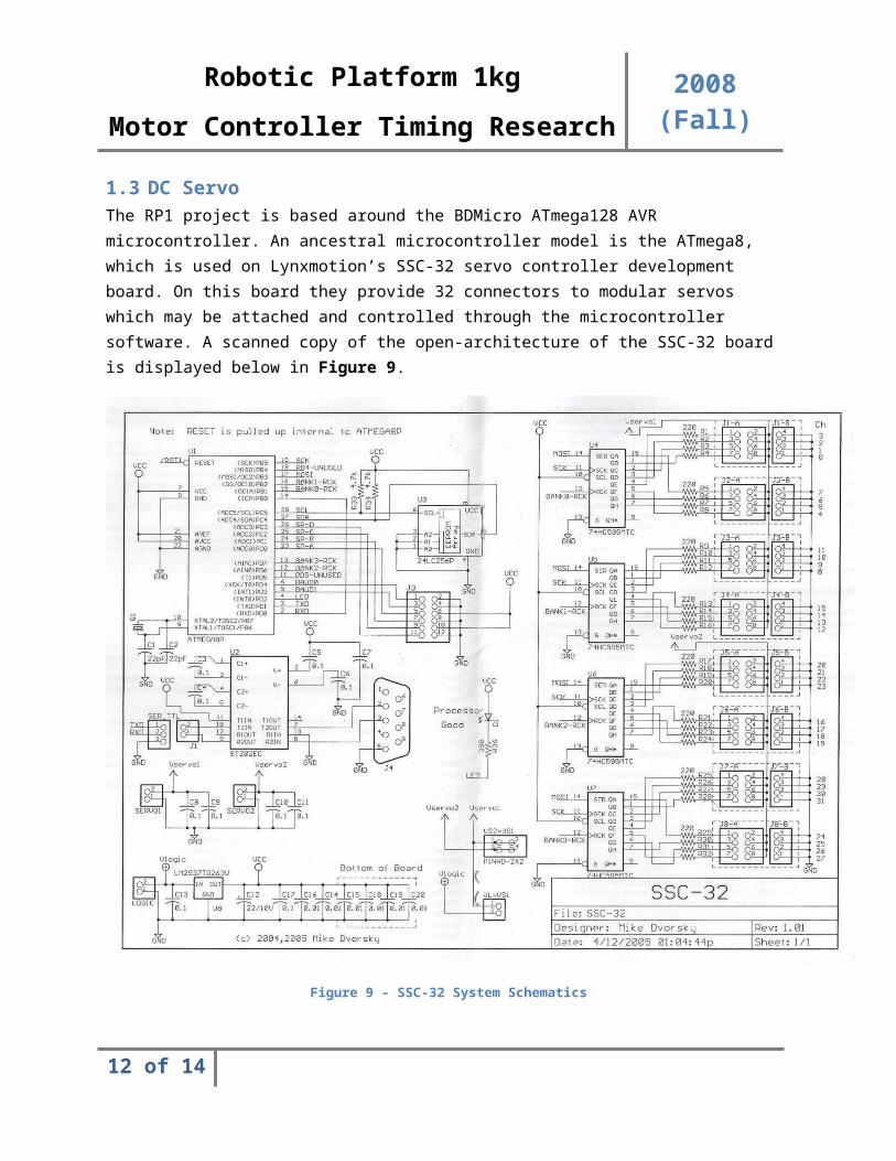
1.3 DC ServoThe RP1 project is based around the BDMicro ATmega128 AVR microcontroller. An ancestral microcontroller model is the ATmega8, which is used on Lynxmotion’s SSC-32 servo controller development board. On this board they provide 32 connectors to modular servos which may be attached and controlled through the microcontroller software. A scanned copy of the open-architecture of the SSC-32 board is displayed below in Figure 9.
Figure 9 - SSC-32 System Schematics
Upon later revision of this document, detail will be put into describing how the ATmega8 microprocessor utilizes the multiple 74HC595MTC 8-bit serial shift registers to control external servos. The interest into the SSC-32 design is to be able to reproduce the part of the design which uniquely controls servos for the ATmega128. Due to the development boards sharing microprocessors within a common family, this should not be difficult to reproduce.
10 of 12
Robotic Platform 1kg
2008 (Fall)Motor Controller Timing Research
1.4 DC Brushed MotorThe RP1 project is based around the BDMicro ATmega128 AVR microcontroller. This microcontroller may support up to four Pulse Width Modulation (PWM) channels. Research has been put into locating cheap, easily configurable PWM Integrated Circuits (ICs), but few exist on the market which meet our criteria.
An off-chip pulse width modulator circuit can be made using a potentiometer to vary the pulse width, however this is difficult to control digitally through a microcontroller. A basic PWM circuit schematic and PWM generation details and sampled waveforms are described in detail in the PWM Design link in section below.
However, generating and controlling a PWM signal will be all that is necessary for the motor controller design. The H-Bridge, which will not be a part of the motor module controller but rather will reside outside the scope of the timing circuitry, will be the only other required part of the DC brushed motor module system and will also control motor rotation direction.
It should be noted that unlike the open-loop stepper motor and servo systems, the DC Brushed motor system will require encoder feedback to accurately control precise movement.
2 AcronymsAcronym Description
RP1 Robotic Platform 1ICD Interface Control DocumentGUI Graphical User InterfaceJRE JAVA Runtime EnvironmentCLI Command Line Interface
OpSoft Operational SoftwareRTOS Real Time Operating System
PC Personal Computer (Desktop or Laptop)SCD Software Control Document
PWM Pulse Width ModulationIC Integrated Circuit
Figure 10 - Table of Acronyms
3 Document ReferencesDocument Location or Link
Stepper Motor Basics http://www.electojects.com/motors/stepper-motors-1.htm
Parallax 4-Phase Unipolar Stepper
http://www.parallax.com/Store/Education/CustomKits/tabid/134/List/1/ProductID/65/Default.aspx?txtSearch=stepper+motor&SortField=ProductName%2cProductName
SSC-32 Stepper Motor Controller http://www.trossenrobotics.com/store/p/3191-SSC-32-Servo-Controller.aspx
Interface Control Document http://edge.rit.edu/content/P09204/public/Interface%20Control%20Document.pdf
11 of 12
Robotic Platform 1kg
2008 (Fall)Motor Controller Timing Research
Document Location or LinkWikipedia Stepper Motor Article http://en.wikipedia.org/wiki/Stepper_motor
Pulse Width Modulator Design http://www.cpemma.co.uk/pwm.html
Figure 11 - Table of References
12 of 12