Embed Size (px)
Citation preview
ROBOTICS
Product manualIRB 4400

Trace back information:Workspace 20B version a15Checked in 2020-06-01Skribenta version 5.3.033
Product manualIRB 4400/60
IRB 4400/L10M2000, IRC5
Document ID: 3HAC022032-001Revision: T
© Copyright 2004-2020 ABB. All rights reserved.Specifications subject to change without notice.
The information in this manual is subject to change without notice and should notbe construed as a commitment by ABB. ABB assumes no responsibility for any errorsthat may appear in this manual.Except as may be expressly stated anywhere in this manual, nothing herein shall beconstrued as any kind of guarantee or warranty by ABB for losses, damage to personsor property, fitness for a specific purpose or the like.In no event shall ABB be liable for incidental or consequential damages arising fromuse of this manual and products described herein.This manual and parts thereof must not be reproduced or copied without ABB'swritten permission.Keep for future reference.Additional copies of this manual may be obtained from ABB.
Original instructions.
© Copyright 2004-2020 ABB. All rights reserved.Specifications subject to change without notice.
Table of contents9Overview of this manual ...................................................................................................................
13Product documentation, M2000/M2000A .........................................................................................14Product documentation, IRC5 ..........................................................................................................16How to read the product manual ......................................................................................................
171 Safety171.1 Safety information .............................................................................................171.1.1 Limitation of liability .................................................................................181.1.2 Requirements on personnel ......................................................................191.2 Safety signals and symbols .................................................................................191.2.1 Safety signals in the manual ......................................................................211.2.2 Safety symbols on manipulator labels .........................................................271.3 Robot stopping functions ....................................................................................281.4 Installation and commissioning ............................................................................311.5 Operation ........................................................................................................311.5.1 Unexpected movement of robot arm ...........................................................321.6 Maintenance and repair ......................................................................................321.6.1 Maintenance and repair ............................................................................351.6.2 Emergency release of the robot axes ..........................................................361.6.3 Brake testing ..........................................................................................371.7 Troubleshooting ................................................................................................381.8 Decommissioning ..............................................................................................
392 Installation and commissioning392.1 Introduction to installation and commissioning .......................................................402.2 Installation and operational requirements for Foundry Prime robots ............................442.2.1 Shut-down periods ..................................................................................452.3 Unpacking .......................................................................................................452.3.1 Pre-installation procedure .........................................................................492.3.2 Working range ........................................................................................522.3.3 The unit is sensitive to ESD .......................................................................532.4 On-site installation ............................................................................................532.4.1 Lifting robot with roundslings ....................................................................562.4.2 Manually releasing the brakes ...................................................................592.4.3 Orienting and securing the robot ................................................................622.4.4 Fitting equipment on the robot ...................................................................622.4.4.1 Mounting equipment ....................................................................652.4.5 Loads fitted to the robot, stopping time and braking distances .........................662.5 Restricting the working range ..............................................................................662.5.1 Axes with restricted working range .............................................................672.5.2 Mechanically restricting the working range of axis 1 ......................................702.5.3 Mechanically restricting the working range of axis 2 ......................................732.5.4 Electrically restricting the working range of axis 3 .........................................752.5.5 Unlimited working range ...........................................................................772.5.6 Risk of tipping/stability .............................................................................782.6 Electrical connections ........................................................................................782.6.1 Customer connection on robot ...................................................................802.6.2 Customer connections on upper arm ..........................................................822.7 Additional installation, Foundry Prime ...................................................................822.7.1 Installation of IRB 4400 in a water jet application ...........................................862.7.2 Commissioning (Foundry Prime) ................................................................872.8 Start of robot in cold environments ......................................................................
893 Maintenance893.1 Introduction ......................................................................................................903.2 Introduction for Foundry Prime robots ...................................................................
Product manual - IRB 4400 53HAC022032-001 Revision: T
© Copyright 2004-2020 ABB. All rights reserved.
Table of contents
913.3 Maintenance schedule .......................................................................................913.3.1 Specification of maintenance intervals ........................................................923.3.2 Maintenance schedule .............................................................................943.4 Inspection activities ...........................................................................................943.4.1 Inspecting information labels .....................................................................963.4.2 Inspecting Signal lamp (option) ..................................................................983.4.3 Inspection of mechanical stop, axis 1 ..........................................................
1003.4.4 Inspection of air hoses (Foundry Prime) ......................................................1023.4.5 Inspection of surface treatment (Foundry Prime) ...........................................1033.5 General maintenance activities ............................................................................1033.5.1 Replacing the SMB battery ........................................................................1053.5.2 Cleaning the IRB 4400 ..............................................................................1093.6 Changing and inspecting oil ................................................................................1093.6.1 Type of lubrication in gearboxes ................................................................1103.6.2 Inspection of oil levels ..............................................................................1133.6.3 Oil change, gearbox axis 4 ........................................................................1163.6.4 Oil change, gearbox axis 5 and 6 (all robot versions) .....................................1193.6.5 Oil change, gearbox axis 5 and 6 (IRB 4400/L10 only) ....................................1223.7 Service Information System, M2000 ......................................................................1223.7.1 Using the SIS system ...............................................................................1233.7.2 Description of Service Information System (SIS) ...........................................1263.7.3 SIS system parameters ............................................................................1273.7.4 Setting the SIS parameters .......................................................................1283.7.5 Reading the SIS output logs ......................................................................1293.7.6 Exporting the SIS data .............................................................................
1314 Repair1314.1 Introduction ......................................................................................................1324.2 General procedures ...........................................................................................1324.2.1 Mounting instructions for bearings .............................................................1344.2.2 Mounting instructions for sealings ..............................................................1374.2.3 Cut the paint or surface on the robot before replacing parts ............................1394.2.4 Performing a leak-down test ......................................................................1404.2.5 The brake release buttons may be jammed after service work .........................1414.3 Complete robot .................................................................................................1414.3.1 Replacement of cable harness, axes 1-3 ......................................................1464.3.2 Replacement of cable harness, axes 4-6 ......................................................1534.3.3 Replacement of complete arm system .........................................................1584.4 Upper arm .......................................................................................................1584.4.1 Replacement of complete upper arm ...........................................................1634.4.2 Replacement of wrist unit .........................................................................1674.4.3 Replacement of arm house unit, axis 4 ........................................................1704.4.4 Replacement of mechanical stop, axis 4 ......................................................1734.4.5 Replacement of signal cabling, upper arm (option 042) ...................................1774.4.6 Measuring the play, axis 5 .........................................................................1804.4.7 Measuring the play, axis 6 .........................................................................1834.5 Lower arm .......................................................................................................1834.5.1 Replacement of lower arm ........................................................................1874.5.2 Replacement of tie rod .............................................................................1914.5.3 Replacement of parallel arm / Replacement of bearing ...................................1954.6 Frame and base ................................................................................................1954.6.1 Replacement of balancing device ...............................................................2034.6.2 Replacement of serial measurement unit .....................................................2074.6.3 Replacement of the brake release board ......................................................2114.6.4 Replacement of mechanical stop pin, axis 1 .................................................2134.7 Motors ............................................................................................................2134.7.1 Replacement of motor, axis 1 ....................................................................2184.7.2 Replacement of motor, axis 2 ....................................................................2234.7.3 Replacement of motor, axis 3 ....................................................................
6 Product manual - IRB 44003HAC022032-001 Revision: T
© Copyright 2004-2020 ABB. All rights reserved.
Table of contents
2274.7.4 Adjustment of motors, axes 1-3 ..................................................................2294.7.5 Removal of motor, axes 4, 5 and 6 ..............................................................2314.7.6 Refitting of motor, axis 4 ...........................................................................2354.7.7 Refitting of motor, axis 5 ...........................................................................2394.7.8 Refitting of motor, axis 6 ...........................................................................2434.8 Gearboxes .......................................................................................................2434.8.1 Replacement of gearbox unit, axes 1-2-3 .....................................................2494.8.2 Adjusting play on axis 4, intermediate gear ..................................................2514.9 Additional repair routines for Foundry Prime ..........................................................2514.9.1 Repair routines .......................................................................................
2595 Calibration2595.1 When to calibrate .............................................................................................2605.2 Calibration methods ...........................................................................................2635.3 Synchronization marks and synchronization position for axes ...................................2655.4 Calibration movement directions for all axes ..........................................................2665.5 Updating revolution counters ...............................................................................2715.6 Checking the synchronization position ..................................................................2735.7 Calibrating with Calibration Pendulum method .......................................................2745.8 Calibrating with Wrist Optimization method ...........................................................2755.9 Additional calibration instruction, IRB 4400 ............................................................
2776 Decommissioning2776.1 Environmental information ..................................................................................2796.2 Decommissioning of balancing device ...................................................................2816.3 Scrapping of robot .............................................................................................
2837 Reference information2837.1 Introduction ......................................................................................................2847.2 Applicable standards .........................................................................................2867.3 Unit conversion .................................................................................................2877.4 Screw joints ....................................................................................................2907.5 Weight specifications .........................................................................................2917.6 Standard tools ..................................................................................................2927.7 Special tools ....................................................................................................2937.8 Lifting accessories and lifting instructions ..............................................................
2958 Spare Part lists2958.1 Spare part lists and illustrations ...........................................................................
2979 Circuit diagram2979.1 Circuit diagrams ................................................................................................
299Index
Product manual - IRB 4400 73HAC022032-001 Revision: T
© Copyright 2004-2020 ABB. All rights reserved.
Table of contents

This page is intentionally left blank
Overview of this manualAbout this manual
This manual contains instructions for• mechanical and electrical installation of the robot• maintenance of the robot• mechanical and electrical repair of the robot.
The manual also contains reference information for all procedures detailed in themanual.
UsageThis manual should be used during
• installation, from lifting the robot to its work site and securing it to thefoundation to making it ready for operation
• maintenance work• repair work.
Who should read this manual?This manual is intended for:
• installation personnel• maintenance personnel• repair personnel.
PrerequisitesMaintenance/repair/installation personnel working with an ABB Robot must:
• be trained by ABB and have the required knowledge of mechanical andelectrical installation/repair/maintenance work.
Product manual scopeThe manual covers covers all variants and designs of the IRB 4400. Some variantsand designs may have been removed from the business offer and are no longeravailable for purchase.
Organization of chaptersThe manual is organized in the following chapters:
ContentsChapter
Safety informationSafety, service
Information about installation of the robot.Installation and commissioning
Information about maintenance work, including mainten-ance schedules.
Maintenance
Information about repair work.Repair
Procedures that does not require specific calibrationequipment. General information about calibration.
Calibration information
Continues on next pageProduct manual - IRB 4400 93HAC022032-001 Revision: T
© Copyright 2004-2020 ABB. All rights reserved.
Overview of this manual
ContentsChapter
Environmental information about the robot and its compon-ents.
Decommissioning
Useful information when performing installation, mainten-ance or repair work (lists of necessary tools, referencedocuments, safety standards)
Reference information
Complete list of robot parts, shown in the partlistPart list
Detailed illustrations of the robot with reference numbersto the part list.
Exploded views
Reference to the circuit diagram for the robot.Circuit diagram
References
NoteDocument IDDocument name
3HAC9117-1Product specification - IRB 4400
3HAC049107-001Product manual, spare parts - IRB 4400
3HAC9821-1Circuit diagram - IRB 4400/4450S
M20043HAC031045-001Safety manual for robot - Manipulator and IRC5or OmniCore controller i
M20043HAC021313-001Product manual - IRC5IRC5 with main computer DSQC 639.
3HAC047136-001Product manual - IRC5IRC5 with main computer DSQC1000.
M20043HAC050941-001Operating manual - IRC5 with FlexPendant
3HAC16578-1Operating manual - Calibration Pendulum
3HAC030421-001Application manual - CalibWare Field
3HAC042927-001Technical reference manual - Lubrication in gear-boxes
3HAC050944-001Operating manual - Service Information System
M20043HAC051016-001Application manual - Additional axes and standalone controlleri This manual contains all safety instructions from the product manuals for the manipulators and the
controllers.
Revisions
DescriptionRevision
First edition.-Replaces previous manuals:
• Installation and Commissioning Manual• Maintenance Manual• Repair Manual, part 1• Repair Manual, part 2.
Changes made in the material from the previous manuals:• Model M2004 implemented.
Continues on next page10 Product manual - IRB 4400
3HAC022032-001 Revision: T© Copyright 2004-2020 ABB. All rights reserved.
Overview of this manualContinued
DescriptionRevision
Chapter Safety, service replaced with chapter Safety.AChapter Calibration replaced with chapter Calibration information.Removed chapter Calibration, M2004.Section Document references is completed with article numbers for calibrationmanuals.
Yaskawa motors been added.B
Robot model IRB 4450S added.C
Foundry Prime (Water jet application) added.D
The protection type Clean Room is added.EChanges made in:
• Prerequisites in section Overview• Oil change in section Maintenance
Content updated in chapter/section:• Section What is an emergency stop? added to chapter Safety• Maintenance/Maintenance schedule: Interval for replacement of battery
pack changed• Maintenance/Cleaning of robot
F
Missing spare part in chapter Spare parts, section Upper arm, axes 4-6, added:• Item 29, Gear axis 6
G
This revision includes the following updates:• Inspection of surface treatment added to maintenance schedule (Foundry
Prime)• Circuit diagrams are not included in this document but delivered as
separate files. See Circuit diagram on page 297.• List of applicable safety standards updated.• Decommissioning chapter added.
The chapter Safety updated with:• Updated safety signal graphics for the levels Danger and Warning.
Safety signals in the manual:• New safety labels on the manipulator.• Revised terminology: robot replaced with manipulator.
H
This revision includes the following updates:• All information about IRB 4400-45, IRB 4400-L10, IRB 4400-L30, IRB
4400-S and IRB 4450S is removed from the manual.• A new block, about general illustrations, added in section How to read
the product manual on page 16.• Some general tightening torques have been changed/added, see updated
values in Screw joints on page 287.• Added information about batteries.• All data about type of lubrication in gearboxes is moved from the
manual to a separate lubrication manual, see Type and amount of oil ingearboxes on page 109.
• A new SMB unit and battery is introduced, with longer battery lifetime.
J
This revision includes the following updates:• The SMB unit backup battery of type NiCad, is no longer available as a
spare part. Therefor removed from this manual.• Added information about risks when scrapping a decommissioned robot,
see Scrapping of robot on page 281.• Spare parts and exploded views are not included in this document but
delivered as a separate document. SeeProductmanual, spare parts - IRB4400.
• The variant IRB 4400/L10 is added.
K
Continues on next pageProduct manual - IRB 4400 113HAC022032-001 Revision: T
© Copyright 2004-2020 ABB. All rights reserved.
Overview of this manualContinued
DescriptionRevision
This revision includes the following updates:• Minor corrections.
L
This revision includes the following updates:• Turning disc fixture is removed from special tools for Levelmeter calib-
ration.• Information about mounting guard plate at push button unit for brake
release added.
M
Published in release R16.2. The following updates are done in this revision:• Corrections due to updates in terminology.• Location of labels figure added.
N
Published in release R17.2. The following updates are done in this revision:• Information about coupled axes in Updating revolution counters on
page 266.• Caution about removing metal residues added in sections about SMB
boards.• Information about minimum resonance frequency added.• Updated list of applicable standards.• Drawing view for extra equipment holes updated.• Section Start of robot in cold environments on page 87 added.• Updated information regarding replacement of brake release board.• Added section to safety chapter: The brake release buttons may be
jammed after service work on page 140.• Updated the description of dimensions (pos A) Mounting equipment on
page 62).• Updated information regarding disconnecting and reconnecting battery
cable to serial measurement board.
P
Published in release R18.1. The following updates are done in this revision:• Added sections in General procedures on page 132.• Safety restructured.• Updated spare part number brake release board unit (was DSQC563, is
DSQC1050).• Information about myABB Business Portal added.• Added Nickel in Environmental information.
Q
Published in release R18.2. The following updates are done in this revision:• Updated spare part number of gearbox unit for axes 1-3.
R
Published in release 19B. The following updates are made in this revision:• New touch up color Graphite White available. SeeCut the paint or surface
on the robot before replacing parts on page 137.• Levelmeter 2000 kit (6369901-347) no longer available.
S
Published in release 20B. The following updates are made in this revision:• Clarified and added information in mounting instructions for rotating
sealings, see Mounting instructions for sealings on page 134.• Added information about Wrist Optimization and Pendulum Calibration
in calibration chapter.• Replaced article number and name of grease, previously 3HAB3537-1.
T
12 Product manual - IRB 44003HAC022032-001 Revision: T
© Copyright 2004-2020 ABB. All rights reserved.
Overview of this manualContinued
Product documentation, M2000/M2000AGeneral
The complete product documentation kit for the M2000 robot system, includingcontroller, robot and any hardware option, consists of the manuals listed below:
Product manualsManipulators, controllers, DressPack/SpotPack, and most other hardware will bedelivered with a Product manual that generally contains:
• Safety information.• Installation and commissioning (descriptions of mechanical installation or
electrical connections).• Maintenance (descriptions of all required preventive maintenance procedures
including intervals and expected life time of parts).• Repair (descriptions of all recommended repair procedures including spare
parts).• Calibration.• Decommissioning.• Reference information (safety standards, unit conversions, screw joints, lists
of tools ).• Spare parts list with exploded views (or references to separate spare parts
lists).• Circuit diagrams (or references to circuit diagrams).
Software manualsThe software documentation consists of a wide range of manuals, ranging frommanuals for basic understanding of the operating system to manuals for enteringparameters during operation.A complete listing of all available software manuals is available from ABB.
Controller hardware option manualEach hardware option for the controller is supplied with its own documentation.Each document set contains the types of information specified below:
• Installation information• Repair information• Maintenance information
In addition, spare part information is supplied for the entire option.
Product manual - IRB 4400 133HAC022032-001 Revision: T
© Copyright 2004-2020 ABB. All rights reserved.
Product documentation, M2000/M2000A
Product documentation, IRC5Categories for user documentation from ABB Robotics
The user documentation from ABB Robotics is divided into a number of categories.This listing is based on the type of information in the documents, regardless ofwhether the products are standard or optional.All documents can be found via myABB Business Portal, www.myportal.abb.com.
Product manualsManipulators, controllers, DressPack/SpotPack, and most other hardware isdelivered with a Product manual that generally contains:
• Safety information.• Installation and commissioning (descriptions of mechanical installation or
electrical connections).• Maintenance (descriptions of all required preventive maintenance procedures
including intervals and expected life time of parts).• Repair (descriptions of all recommended repair procedures including spare
parts).• Calibration.• Decommissioning.• Reference information (safety standards, unit conversions, screw joints, lists
of tools).• Spare parts list with corresponding figures (or references to separate spare
parts lists).• References to circuit diagrams.
Technical reference manualsThe technical reference manuals describe reference information for roboticsproducts, for example lubrication, the RAPID language, and system parameters.
Application manualsSpecific applications (for example software or hardware options) are described inApplication manuals. An application manual can describe one or severalapplications.An application manual generally contains information about:
• The purpose of the application (what it does and when it is useful).• What is included (for example cables, I/O boards, RAPID instructions, system
parameters, software).• How to install included or required hardware.• How to use the application.• Examples of how to use the application.
Continues on next page14 Product manual - IRB 4400
3HAC022032-001 Revision: T© Copyright 2004-2020 ABB. All rights reserved.
Product documentation, IRC5
Operating manualsThe operating manuals describe hands-on handling of the products. The manualsare aimed at those having first-hand operational contact with the product, that isproduction cell operators, programmers, and troubleshooters.
Product manual - IRB 4400 153HAC022032-001 Revision: T
© Copyright 2004-2020 ABB. All rights reserved.
Product documentation, IRC5Continued
How to read the product manualReading the procedures
The procedures contain references to figures, tools, material, and so on. Thereferences are read as described below.
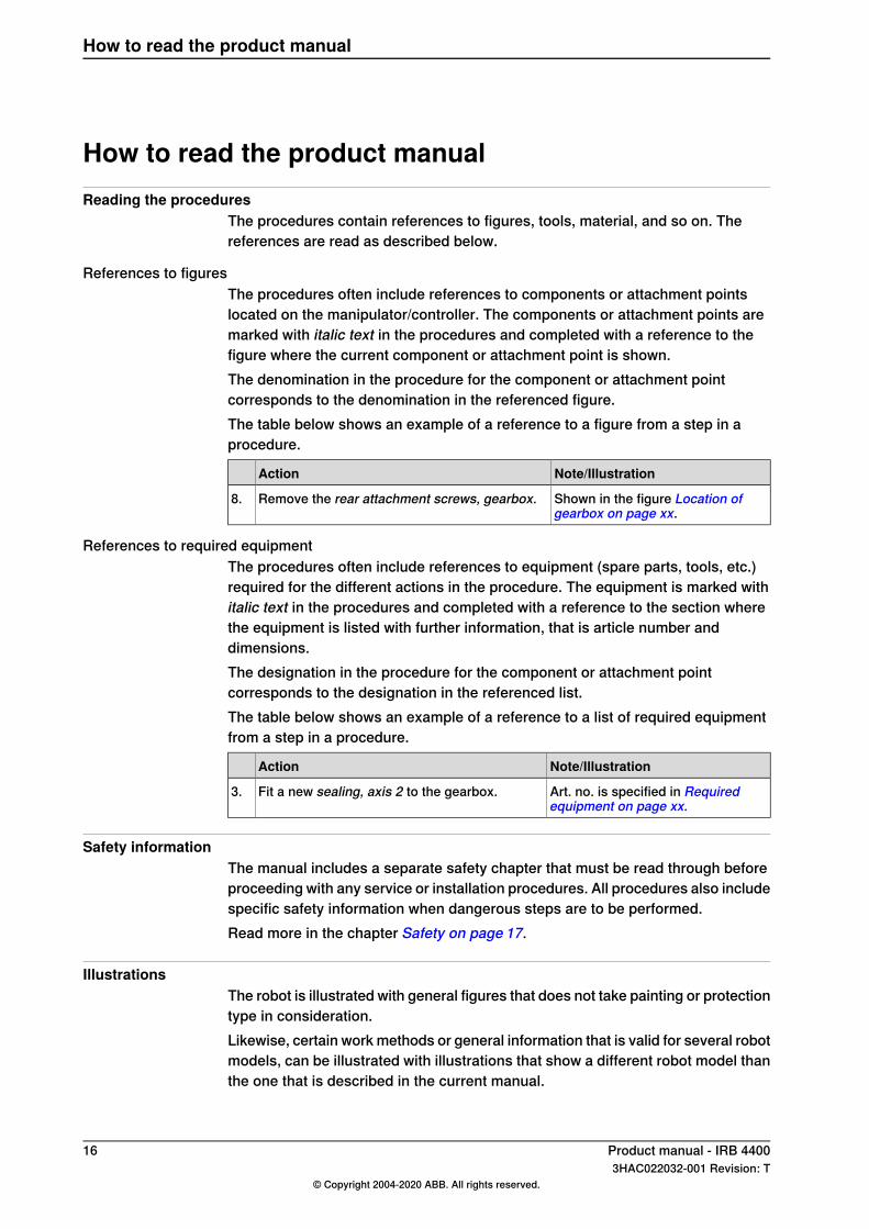
References to figuresThe procedures often include references to components or attachment pointslocated on the manipulator/controller. The components or attachment points aremarked with italic text in the procedures and completed with a reference to thefigure where the current component or attachment point is shown.The denomination in the procedure for the component or attachment pointcorresponds to the denomination in the referenced figure.The table below shows an example of a reference to a figure from a step in aprocedure.
Note/IllustrationAction
Shown in the figure Location ofgearbox on page xx.
Remove the rear attachment screws, gearbox.8.
References to required equipmentThe procedures often include references to equipment (spare parts, tools, etc.)required for the different actions in the procedure. The equipment is marked withitalic text in the procedures and completed with a reference to the section wherethe equipment is listed with further information, that is article number anddimensions.The designation in the procedure for the component or attachment pointcorresponds to the designation in the referenced list.The table below shows an example of a reference to a list of required equipmentfrom a step in a procedure.
Note/IllustrationAction
Art. no. is specified in Requiredequipment on page xx.
Fit a new sealing, axis 2 to the gearbox.3.
Safety informationThe manual includes a separate safety chapter that must be read through beforeproceeding with any service or installation procedures. All procedures also includespecific safety information when dangerous steps are to be performed.Read more in the chapter Safety on page 17.
IllustrationsThe robot is illustrated with general figures that does not take painting or protectiontype in consideration.Likewise, certain work methods or general information that is valid for several robotmodels, can be illustrated with illustrations that show a different robot model thanthe one that is described in the current manual.
16 Product manual - IRB 44003HAC022032-001 Revision: T
© Copyright 2004-2020 ABB. All rights reserved.
How to read the product manual
1 Safety1.1 Safety information
1.1.1 Limitation of liability
Limitation of liabilityAny information given in this manual regarding safety must not be construed as awarranty by ABB that the industrial robot will not cause injury or damage even ifall safety instructions are complied with.The information does not cover how to design, install and operate a robot system,nor does it cover all peripheral equipment that can influence the safety of the robotsystem.In particular, liability cannot be accepted if injury or damage has been caused forany of the following reasons:
• Use of the robot in other ways than intended.• Incorrect operation or maintenance.• Operation of the robot when the safety devices are defective, not in their
intended location or in any other way not working.• When instructions for operation and maintenance are not followed.• Non-authorized design modifications of the robot.• Repairs on the robot and its spare parts carried out by in-experienced or
non-qualified personnel.• Foreign objects.• Force majeure.
Spare parts and equipmentABB supplies original spare parts and equipment which have been tested andapproved. The installation and/or use of non-original spare parts and equipmentcan negatively affect the safety, function, performance, and structural propertiesof the robot. ABB is not liable for damages caused by the use of non-original spareparts and equipment.
Product manual - IRB 4400 173HAC022032-001 Revision: T
© Copyright 2004-2020 ABB. All rights reserved.
1 Safety1.1.1 Limitation of liability
1.1.2 Requirements on personnel
GeneralOnly personnel with appropriate training are allowed to install, maintain, service,repair, and use the robot. This includes electrical, mechanical, hydraulics,pneumatics, and other hazards identified in the risk assessment.Persons who are under the influence of alcohol, drugs or any other intoxicatingsubstances are not allowed to install, maintain, service, repair, or use the robot.The plant liable must make sure that the personnel is trained on the robot, and onresponding to emergency or abnormal situations.
Personal protective equipmentUse personal protective equipment, as stated in the product manual.
18 Product manual - IRB 44003HAC022032-001 Revision: T
© Copyright 2004-2020 ABB. All rights reserved.
1 Safety1.1.2 Requirements on personnel
1.2 Safety signals and symbols
1.2.1 Safety signals in the manual
Introduction to safety signalsThis section specifies all safety signals used in the user manuals. Each signalconsists of:
• A caption specifying the hazard level (DANGER, WARNING, or CAUTION)and the type of hazard.
• Instruction about how to reduce the hazard to an acceptable level.• A brief description of remaining hazards, if not adequately reduced.
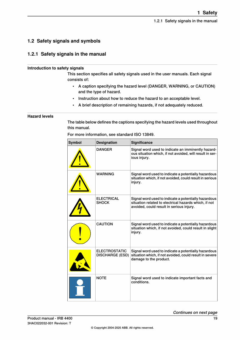
Hazard levelsThe table below defines the captions specifying the hazard levels used throughoutthis manual.For more information, see standard ISO 13849.
SignificanceDesignationSymbol
Signal word used to indicate an imminently hazard-ous situation which, if not avoided, will result in ser-ious injury.
DANGER
Signal word used to indicate a potentially hazardoussituation which, if not avoided, could result in seriousinjury.
WARNING
Signal word used to indicate a potentially hazardoussituation related to electrical hazards which, if notavoided, could result in serious injury.
ELECTRICALSHOCK
Signal word used to indicate a potentially hazardoussituation which, if not avoided, could result in slightinjury.
CAUTION
Signal word used to indicate a potentially hazardoussituation which, if not avoided, could result in severedamage to the product.
ELECTROSTATICDISCHARGE (ESD)
Signal word used to indicate important facts andconditions.
NOTE
Continues on next pageProduct manual - IRB 4400 193HAC022032-001 Revision: T
© Copyright 2004-2020 ABB. All rights reserved.
1 Safety1.2.1 Safety signals in the manual
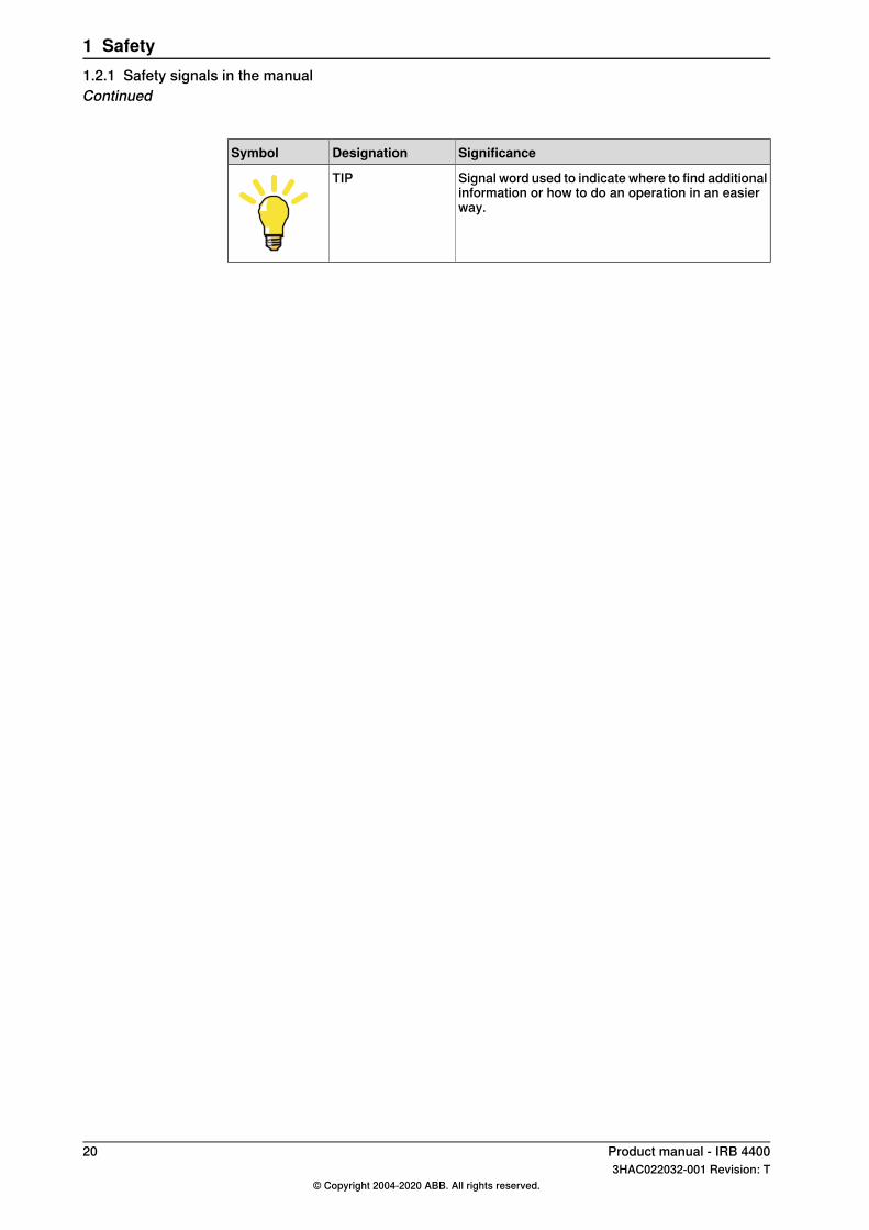
SignificanceDesignationSymbol
Signal word used to indicate where to find additionalinformation or how to do an operation in an easierway.
TIP
20 Product manual - IRB 44003HAC022032-001 Revision: T
© Copyright 2004-2020 ABB. All rights reserved.
1 Safety1.2.1 Safety signals in the manualContinued
1.2.2 Safety symbols on manipulator labels
Introduction to symbolsThis section describes safety symbols used on labels (stickers) on the manipulator.Symbols are used in combinations on the labels, describing each specific warning.The descriptions in this section are generic, the labels can contain additionalinformation such as values.
Note
The symbols on the labels on the product must be observed. Additional symbolsadded by the integrator must also be observed.
Types of symbolsBoth the manipulator and the controller are marked with symbols, containingimportant information about the product. This is important for all personnel handlingthe robot, for example during installation, service, or operation.The safety labels are language independent, they only use graphics. See Symbolson safety labels on page 21.The information labels can contain information in text.
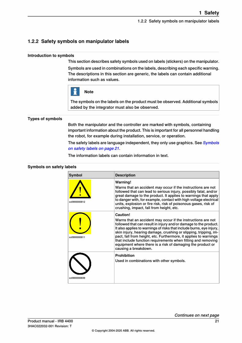
Symbols on safety labels
DescriptionSymbol
Warning!
xx0900000812
Warns that an accident may occur if the instructions are notfollowed that can lead to serious injury, possibly fatal, and/orgreat damage to the product. It applies to warnings that applyto danger with, for example, contact with high voltage electricalunits, explosion or fire risk, risk of poisonous gases, risk ofcrushing, impact, fall from height, etc.
Caution!
xx0900000811
Warns that an accident may occur if the instructions are notfollowed that can result in injury and/or damage to the product.It also applies to warnings of risks that include burns, eye injury,skin injury, hearing damage, crushing or slipping, tripping, im-pact, fall from height, etc. Furthermore, it applies to warningsthat include function requirements when fitting and removingequipment where there is a risk of damaging the product orcausing a breakdown.
Prohibition
xx0900000839
Used in combinations with other symbols.
Continues on next pageProduct manual - IRB 4400 213HAC022032-001 Revision: T
© Copyright 2004-2020 ABB. All rights reserved.
1 Safety1.2.2 Safety symbols on manipulator labels
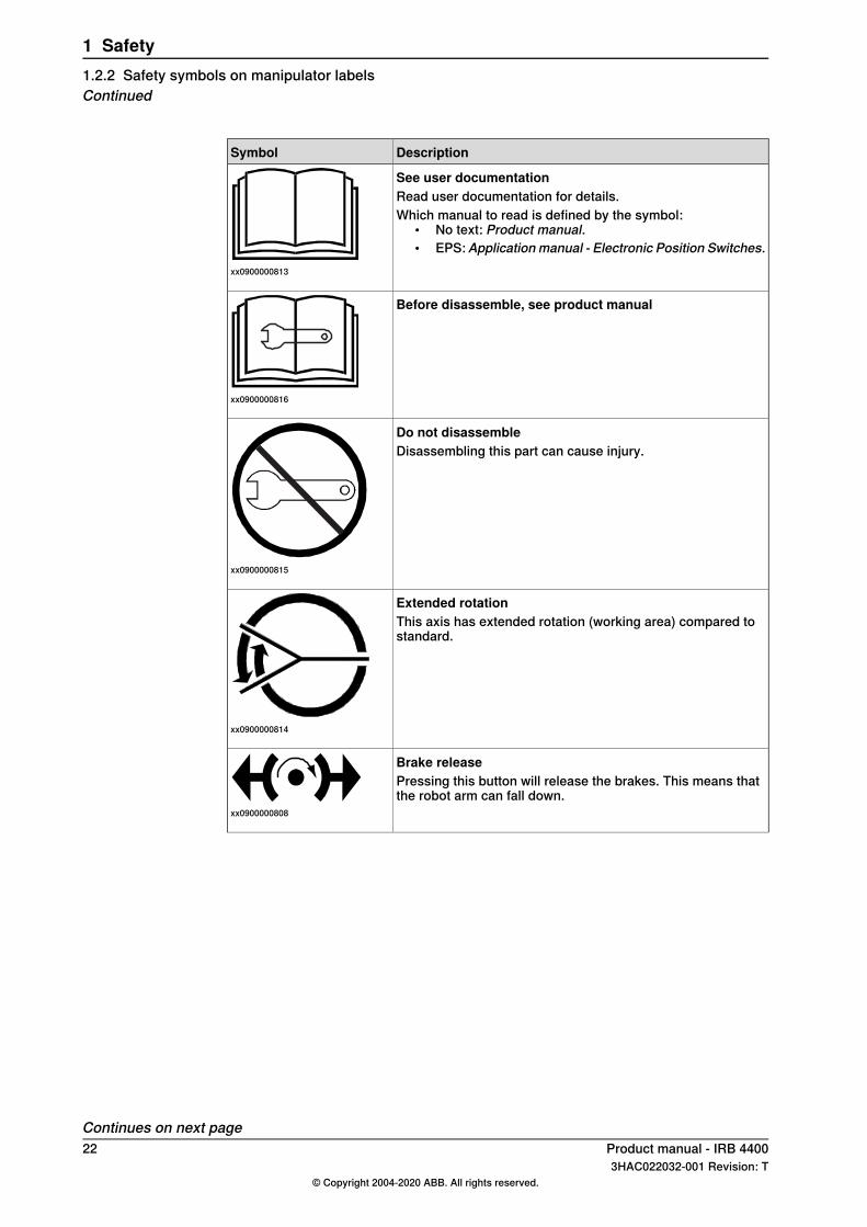
DescriptionSymbol
See user documentation
xx0900000813
Read user documentation for details.Which manual to read is defined by the symbol:
• No text: Product manual.• EPS: Application manual - Electronic Position Switches.
Before disassemble, see product manual
xx0900000816
Do not disassemble
xx0900000815
Disassembling this part can cause injury.
Extended rotation
xx0900000814
This axis has extended rotation (working area) compared tostandard.
Brake release
xx0900000808
Pressing this button will release the brakes. This means thatthe robot arm can fall down.
Continues on next page22 Product manual - IRB 4400
3HAC022032-001 Revision: T© Copyright 2004-2020 ABB. All rights reserved.
1 Safety1.2.2 Safety symbols on manipulator labelsContinued
DescriptionSymbol
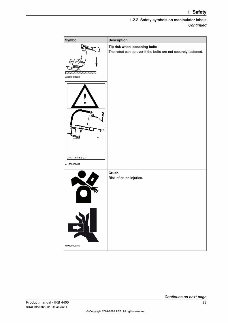
Tip risk when loosening bolts
xx0900000810
The robot can tip over if the bolts are not securely fastened.
xx1500002402
Crush
xx0900000817
Risk of crush injuries.
Continues on next pageProduct manual - IRB 4400 233HAC022032-001 Revision: T
© Copyright 2004-2020 ABB. All rights reserved.
1 Safety1.2.2 Safety symbols on manipulator labels
Continued
DescriptionSymbol
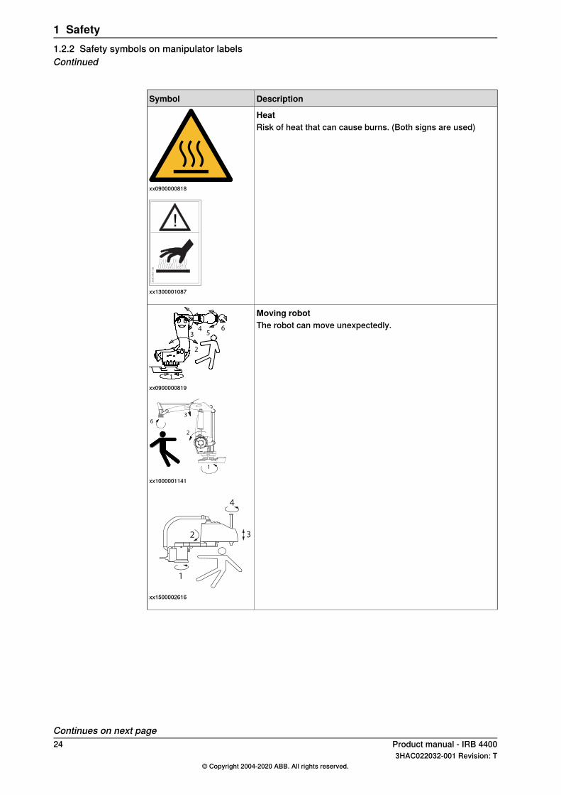
Heat
xx0900000818
Risk of heat that can cause burns. (Both signs are used)
3H
AC
44
31
-1/0
6
!
xx1300001087
Moving robot
1
2
34
56
xx0900000819
The robot can move unexpectedly.
xx1000001141
1
2 3
4
xx1500002616
Continues on next page24 Product manual - IRB 4400
3HAC022032-001 Revision: T© Copyright 2004-2020 ABB. All rights reserved.
1 Safety1.2.2 Safety symbols on manipulator labelsContinued
DescriptionSymbol
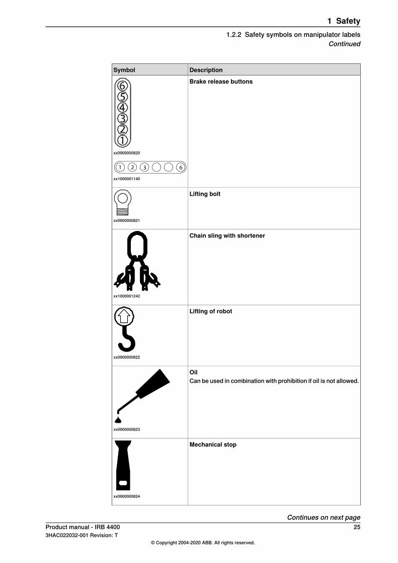
Brake release buttons
xx0900000820
xx1000001140
Lifting bolt
xx0900000821
Chain sling with shortener
xx1000001242
Lifting of robot
xx0900000822
Oil
xx0900000823
Can be used in combination with prohibition if oil is not allowed.
Mechanical stop
xx0900000824
Continues on next pageProduct manual - IRB 4400 253HAC022032-001 Revision: T
© Copyright 2004-2020 ABB. All rights reserved.
1 Safety1.2.2 Safety symbols on manipulator labels
Continued
DescriptionSymbol
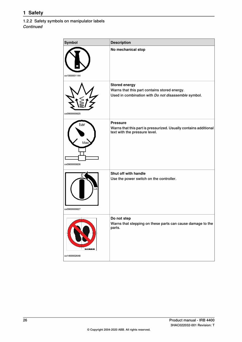
No mechanical stop
xx1000001144
Stored energy
xx0900000825
Warns that this part contains stored energy.Used in combination with Do not disassemble symbol.
Pressure
xx0900000826
Warns that this part is pressurized. Usually contains additionaltext with the pressure level.
Shut off with handle
xx0900000827
Use the power switch on the controller.
Do not step
xx1400002648
Warns that stepping on these parts can cause damage to theparts.
26 Product manual - IRB 44003HAC022032-001 Revision: T
© Copyright 2004-2020 ABB. All rights reserved.
1 Safety1.2.2 Safety symbols on manipulator labelsContinued
1.3 Robot stopping functions
Protective stop and emergency stopThe protective stops and emergency stops are described in the product manualfor the controller.For more information see:
• Product manual - IRC5• Product manual - IRC5 Panel Mounted Controller
Product manual - IRB 4400 273HAC022032-001 Revision: T
© Copyright 2004-2020 ABB. All rights reserved.
1 Safety1.3 Robot stopping functions
1.4 Installation and commissioning
National or regional regulationsThe integrator of the robot system is responsible for the safety of the robot system.The integrator is responsible that the robot system is designed and installed inaccordance with the safety requirements set forth in the applicable national andregional standards and regulations.The integrator of the robot system is required to perform an assessment of thehazards and risks.
LayoutThe robot integrated to a robot system shall be designed to allow safe access toall areas during installation, operation, maintenance, and repair.If robot movement can be initiated from an external control panel then an emergencystop must also be available.If the manipulator is delivered with mechanical stops, these can be used for reducingthe working area.A perimeter safeguarding, for example a fence, shall be dimensioned to withstandthe following:
• The force of the manipulator.• The force of the load handled by the robot if dropped or released at maximum
speed.• The maximum possible impact caused by a breaking or malfunctioning
rotating tool or other device fitted to the robot.The maximum TCP speed and the maximum velocity of the robot axes are detailedin the section Robot motion in the product specification for the respectivemanipulator.Consider exposure to hazards, such as slipping, tripping, and falling.Consider hazards from other equipment in the robot system, for example, thatguards remain active until identified hazards are reduced to an acceptable level.
Allergenic materialSee Environmental information on page277 for specification of allergenic materialsin the product, if any.
Securing the robot to the foundationThe robot must be properly fixed to its foundation/support, as described in theproduct manual.When the robot is installed at a height, hanging, or other than mounted directly onthe floor, there will be additional hazards.
Electrical safetyThe mains power must be installed to fulfill national regulations.
Continues on next page28 Product manual - IRB 4400
3HAC022032-001 Revision: T© Copyright 2004-2020 ABB. All rights reserved.
1 Safety1.4 Installation and commissioning
The power supply wiring to the robot must be sufficiently fused and if necessary,it must be possible to disconnect it manually from the mains power.The power to the robot must be turned off with the main switch and the mainspower disconnected when performing work inside the controller cabinet. Lock andtag shall be considered.Harnesses between controller and manipulator shall be fixed and protected toavoid tripping and wear.
Note
Use a CARBON DIOXIDE (CO2) extinguisher in the event of a fire in the robot.
Safety devicesThe integrator is responsible for that the safety devices necessary to protect peopleworking with the robot system are designed and installed correctly.When integrating the robot with external devices to a robot system:
• The integrator of the robot system must ensure that emergency stop functionsare interlocked in accordance with applicable standards.
• The integrator of the robot system must ensure that safety functions areinterlocked in accordance with applicable standards.
Other hazards
WARNING
Never stay beneath a robot arm. Gravity and the release of braking devices cancreate additional hazards.
A robot may perform unexpected limited movement.
WARNING
Manipulator movements can cause serious injuries on users and may damageequipment.
The risk assessment should also consider other hazards, such as, but not limitedto:
• Water• Compressed air• Hydraulics
Continues on next pageProduct manual - IRB 4400 293HAC022032-001 Revision: T
© Copyright 2004-2020 ABB. All rights reserved.
1 Safety1.4 Installation and commissioning
Continued
Pneumatic or hydraulic related hazards
Note
The pressure in the complete pneumatic or hydraulic systems must be releasedbefore service and maintenance.All components in the robot system that remain pressurized after switching offthe power to the robot must be marked with clearly visible drain facilities and awarning sign that indicates the hazard of stored energy.
Loss of pressure in the robot system may cause parts or objects to drop.Dump valves should be used in case of emergency.Shot bolts should be used to prevent tools, etc., from falling due to gravity.All pipes, hoses, and connections have to be inspected regularly for leaks anddamage. Damage must be repaired immediately.
Verify the safety functionsBefore the robot system is put into operation, verify that the safety functions areworking as intended and that any remaining hazards identified in the riskassessment are mitigated to an acceptable level.
30 Product manual - IRB 44003HAC022032-001 Revision: T
© Copyright 2004-2020 ABB. All rights reserved.
1 Safety1.4 Installation and commissioningContinued
1.5 Operation
1.5.1 Unexpected movement of robot arm
Unexpected movement of robot arm
WARNING
Never stay beneath a robot arm. Gravity and the release of braking devices cancreate additional hazards.
A robot may perform unexpected limited movement.
WARNING
Manipulator movements can cause serious injuries on users and may damageequipment.
Product manual - IRB 4400 313HAC022032-001 Revision: T
© Copyright 2004-2020 ABB. All rights reserved.
1 Safety1.5.1 Unexpected movement of robot arm
1.6 Maintenance and repair
1.6.1 Maintenance and repair
GeneralCorrective maintenance must only be carried out by personnel trained on the robot.Maintenance or repair must be done with all electrical, pneumatic, and hydraulicpower switched off, that is, no remaining hazards.Hazards due to stored mechanical energy in the manipulator for the purpose ofcounterbalancing axes must be considered before maintenance or repair.Never use the robot as a ladder, which means, do not climb on the controller,manipulator, including motors, or other parts. There are hazards of slipping andfalling. The robot might be damaged.Make sure that there are no loose screws, turnings, or other unexpected partsremaining after work on the robot has been performed.When the work is completed, verify that the safety functions are working asintended.
Gearbox lubricants (oil or grease)When handling oil, grease, or other chemical substances the safety information ofthe respective manufacturer must be observed.
Note
Take special care when handling hot lubricants.
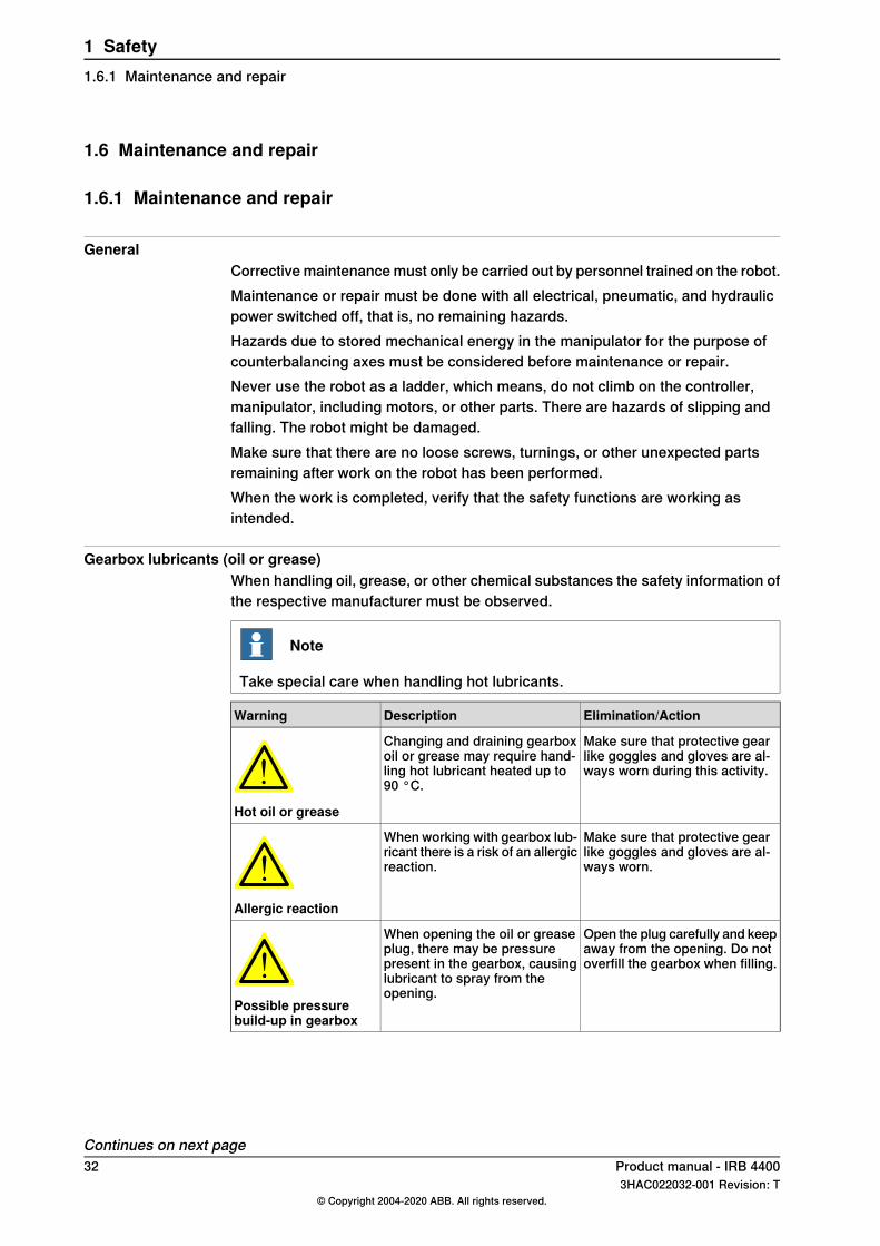
Elimination/ActionDescriptionWarning
Make sure that protective gearlike goggles and gloves are al-ways worn during this activity.
Changing and draining gearboxoil or grease may require hand-ling hot lubricant heated up to90 °C.
Hot oil or grease
Make sure that protective gearlike goggles and gloves are al-ways worn.
When working with gearbox lub-ricant there is a risk of an allergicreaction.
Allergic reaction
Open the plug carefully and keepaway from the opening. Do notoverfill the gearbox when filling.
When opening the oil or greaseplug, there may be pressurepresent in the gearbox, causinglubricant to spray from theopening.
Possible pressurebuild-up in gearbox
Continues on next page32 Product manual - IRB 4400
3HAC022032-001 Revision: T© Copyright 2004-2020 ABB. All rights reserved.
1 Safety1.6.1 Maintenance and repair
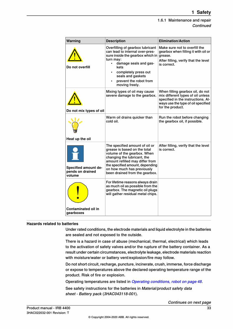
Elimination/ActionDescriptionWarning
Make sure not to overfill thegearbox when filling it with oil orgrease.
Overfilling of gearbox lubricantcan lead to internal over-pres-sure inside the gearbox which inturn may:
• damage seals and gas-kets
• completely press outseals and gaskets
• prevent the robot frommoving freely.
Do not overfill
After filling, verify that the levelis correct.
When filling gearbox oil, do notmix different types of oil unlessspecified in the instructions. Al-ways use the type of oil specifiedfor the product.
Mixing types of oil may causesevere damage to the gearbox.
Do not mix types of oil
Run the robot before changingthe gearbox oil, if possible.
Warm oil drains quicker thancold oil.
Heat up the oil
After filling, verify that the levelis correct.
The specified amount of oil orgrease is based on the totalvolume of the gearbox. Whenchanging the lubricant, theamount refilled may differ fromthe specified amount, dependingon how much has previouslybeen drained from the gearbox.
Specified amount de-pends on drainedvolume
For lifetime reasons always drainas much oil as possible from thegearbox. The magnetic oil plugswill gather residual metal chips.
Contaminated oil ingearboxes
Hazards related to batteriesUnder rated conditions, the electrode materials and liquid electrolyte in the batteriesare sealed and not exposed to the outside.There is a hazard in case of abuse (mechanical, thermal, electrical) which leadsto the activation of safety valves and/or the rupture of the battery container. As aresult under certain circumstances, electrolyte leakage, electrode materials reactionwith moisture/water or battery vent/explosion/fire may follow.Do not short circuit, recharge, puncture, incinerate, crush, immerse, force dischargeor expose to temperatures above the declared operating temperature range of theproduct. Risk of fire or explosion.Operating temperatures are listed in Operating conditions, robot on page 48.See safety instructions for the batteries in Material/product safety datasheet - Battery pack (3HAC043118-001).
Continues on next pageProduct manual - IRB 4400 333HAC022032-001 Revision: T
© Copyright 2004-2020 ABB. All rights reserved.
1 Safety1.6.1 Maintenance and repair
Continued
Unexpected movement of robot arm
WARNING
Never stay beneath a robot arm. Gravity and the release of braking devices cancreate additional hazards.
A robot may perform unexpected limited movement.
WARNING
Manipulator movements can cause serious injuries on users and may damageequipment.
Related informationSee also the safety information related to installation and operation.
34 Product manual - IRB 44003HAC022032-001 Revision: T
© Copyright 2004-2020 ABB. All rights reserved.
1 Safety1.6.1 Maintenance and repairContinued

1.6.2 Emergency release of the robot axes
DescriptionIn an emergency situation, the brakes on a robot axis can be released manuallyby pushing a brake release button.How to release the brakes is described in the section:
• Shut-down periods on page 44.The robot may be moved manually on smaller robot models, but larger modelsmay require using an overhead crane or similar equipment.
Increased injuryBefore releasing the brakes, make sure that the weight of the manipulator doesnot result in additional hazards, for example, even more severe injuries on a trappedperson.
DANGER
When releasing the holding brakes, the robot axes may move very quickly andsometimes in unexpected ways.Make sure no personnel is near or beneath the robot.
Product manual - IRB 4400 353HAC022032-001 Revision: T
© Copyright 2004-2020 ABB. All rights reserved.
1 Safety1.6.2 Emergency release of the robot axes
1.6.3 Brake testing
When to testDuring operation, the holding brake of each axis normally wears down. A test canbe performed to determine whether the brake can still perform its function.
How to testThe function of the holding brake of each axis motor may be verified as describedbelow:
1 Run each axis to a position where the combined weight of the manipulatorand any load is maximized (maximum static load).
2 Switch the motor to the MOTORS OFF.3 Inspect and verify that the axis maintains its position.
If the manipulator does not change position as the motors are switched off,then the brake function is adequate.
36 Product manual - IRB 44003HAC022032-001 Revision: T
© Copyright 2004-2020 ABB. All rights reserved.
1 Safety1.6.3 Brake testing
1.7 Troubleshooting
GeneralWhen troubleshooting requires work with power switched on, special considerationsmust be taken:
• Safety circuits might be muted or disconnected.• Electrical parts must be considered as live.• The manipulator can move unexpectedly at any time.
DANGER
Troubleshooting on the controller while powered on must be performed bypersonnel trained by ABB or by ABB field engineers.
A risk assessment must be done to address both robot and robot system specifichazards.
WARNING
Never stay beneath a robot arm. Gravity and the release of braking devices cancreate additional hazards.
A robot may perform unexpected limited movement.
WARNING
Manipulator movements can cause serious injuries on users and may damageequipment.
Related informationSee also the safety information related to installation, operation, maintenance, andrepair.
Product manual - IRB 4400 373HAC022032-001 Revision: T
© Copyright 2004-2020 ABB. All rights reserved.
1 Safety1.7 Troubleshooting
1.8 Decommissioning
GeneralSee section Decommissioning on page 277.
Unexpected movement of robot arm
WARNING
Never stay beneath a robot arm. Gravity and the release of braking devices cancreate additional hazards.
A robot may perform unexpected limited movement.
WARNING
Manipulator movements can cause serious injuries on users and may damageequipment.
38 Product manual - IRB 44003HAC022032-001 Revision: T
© Copyright 2004-2020 ABB. All rights reserved.
1 Safety1.8 Decommissioning
2 Installation and commissioning2.1 Introduction to installation and commissioning
GeneralThis chapter contains assembly instructions and information for installing the IRB4400 controller at the working site.See also the product manual for the robot controller.The installation must be done by qualified installation personnel in accordancewith the safety requirements set forth in the applicable national and regionalstandards and regulations.
Safety informationBefore any installation work is commenced, it is extremely important that all safetyinformation is observed.There are general safety aspects that must be read through, as well as more specificsafety information that describes the danger and safety risks when performing theprocedures. Read the chapterSafety on page17 before performing any installationwork.
Note
If the IRB 4400 is connected to power, always make sure that the robot isconnected to protective earth and a residual current device (RCD) before startingany installation work.For more information see:
• Product manual - IRC5• Product manual - IRC5 Panel Mounted Controller
Product manual - IRB 4400 393HAC022032-001 Revision: T
© Copyright 2004-2020 ABB. All rights reserved.
2 Installation and commissioning2.1 Introduction to installation and commissioning
2.2 Installation and operational requirements for Foundry Prime robots
IntroductionRobots with protection type Foundry Prime are specially designed to work in harshenvironments. To ensure that the protection offers the best reliability, specialmeasures are required during installation and operation. It is required that theenvironmental and application conditions are fulfilled and that the specialmaintenance activities and intervals for the Foundry Prime protected robot arefollowed.
Fluids in the vicinity of the robotIf fluids that can cause rust formation, for example, water etc., are used in thevicinity of the robot it is required to add rust inhibitor to the fluid or take othermeasures to prevent rust on unpainted joints or other unprotected surfaces of therobot.
Activity to lubricate gearboxes cavities and gearsRun each axis on high speed at least once per hour. This activity will lubricate thegearbox cavities and gears, which reduces the risk for corrosion due tocondensation in the gearboxes.
Pressurized componentsThe motors, the balancing device, and the serial measurement board cavity mustbe pressurized on Foundry Prime robots during operation and shut down. Theoverpressure can be dropped when atmospheric humidity has reached the samelevel as the surrounding environment.At the installation of the Foundry Prime robot a pressure sensor and pressure reliefvalve (not included) must be installed in the air supply system to monitor the supplyof air pressure in order to secure a correct pressure. See Pressurizing equipmenton page 41 for equipment specifications.
Note
The overpressure must be kept at 0.2 - 0.3 ± 0.0 bar during 24 hours independentof Motors On/Off mode, start-up, and shut down periods.
WARNING
Do not to exceed the maximum pressure of 0.3 bar. If the air pressure exceedsthe specified, it can lead to damage to the gearbox or brake failure in the motorswhich may cause the robot arms to fall down, leading to personal injury or physicaldamage.
Continues on next page40 Product manual - IRB 4400
3HAC022032-001 Revision: T© Copyright 2004-2020 ABB. All rights reserved.
2 Installation and commissioning2.2 Installation and operational requirements for Foundry Prime robots
WARNING
If the pressurized air contains oil, it could result in a brake failure in the motorsand cause the robot arms to fall down, leading to personal injury or physicaldamage.
Note
To secure the supply of air pressure, use a pressure sensor.
Air quality for pressurizing of robotThe air must be dry and clean, such as instrument air. The following table describesthe air specifications.
ValueParameter
<+2°C at 6 barDew point
<5 micronsSolid particle size
<1 ppm (1 mg/m3 )Oil content
>200 L/minAir flow
Pressurizing equipmentABB recommends a safety valve (if not included) set at 0.4 bar, pressure sensorset at 0.2-0.3 bar or regulator set for maximum 0.3 bar to be attached on thepressure side of the air system.Example of products:
DescriptionEquipment
Festo SDE1-seriesPressure sensor
Festo LRP-seriesPressure regulator
Connect air hose to over pressure limiter unit
Note
ABB recommends the air pressure to be set at maximum 0.3 bar.
Continues on next pageProduct manual - IRB 4400 413HAC022032-001 Revision: T
© Copyright 2004-2020 ABB. All rights reserved.
2 Installation and commissioning2.2 Installation and operational requirements for Foundry Prime robots
Continued
xx1700000565
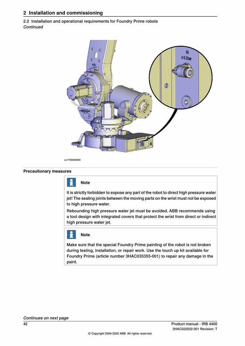
Precautionary measures
Note
It is strictly forbidden to expose any part of the robot to direct high pressure waterjet! The sealing joints between the moving parts on the wrist must not be exposedto high pressure water.Rebounding high pressure water jet must be avoided. ABB recommends usinga tool design with integrated covers that protect the wrist from direct or indirecthigh pressure water jet.
Note
Make sure that the special Foundry Prime painting of the robot is not brokenduring testing, installation, or repair work. Use the touch up kit available forFoundry Prime (article number 3HAC035355-001) to repair any damage in thepaint.
Continues on next page42 Product manual - IRB 4400
3HAC022032-001 Revision: T© Copyright 2004-2020 ABB. All rights reserved.
2 Installation and commissioning2.2 Installation and operational requirements for Foundry Prime robotsContinued
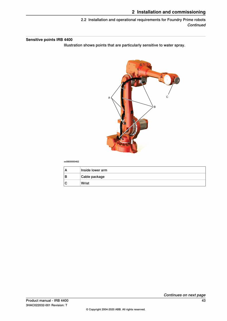
Sensitive points IRB 4400Illustration shows points that are particularly sensitive to water spray.
C
B
A
xx0800000462
Inside lower armA
Cable packageB
WristC
Continues on next pageProduct manual - IRB 4400 433HAC022032-001 Revision: T
© Copyright 2004-2020 ABB. All rights reserved.
2 Installation and commissioning2.2 Installation and operational requirements for Foundry Prime robots
Continued
2.2.1 Shut-down periods
Shut-down periodsDuring shut-down periods the cleaning cell must be ventilated out (aired out). Thisreduces the risk that moister is sucked into gearboxes during cooling down. Itgives the robot the possibility to dry as the rust inhibition effect normally getsreduced after some time.Ventilate and air out the cell during and after shut-downs:
• The cell must be ventilated during shut-down until the atmospheric humidityin the cell has reached the same level as the surrounding environment.
• Will avoid that humid air is trapped into gearboxes or other cavities due toraised vacuum when cooling down.
• Will give the robot a chance to dry as most rust preventive components inwashing detergents have a decaying effect, i.e. the rust preventive effect isreduced after a time. Please refer to the Product Specification of the washingdetergent in question for decaying effect. Washing detergent or water withoutrust inhibitor can give an accelerated corrosion on some robot components.
• The overpressure must be kept at 0.2 - 0.3 ± 0.0 bar during 24 hoursindependent of Motors On/Off mode, start-up and shut-down periods.
44 Product manual - IRB 44003HAC022032-001 Revision: T
© Copyright 2004-2020 ABB. All rights reserved.
2 Installation and commissioning2.2.1 Shut-down periods
2.3 Unpacking
2.3.1 Pre-installation procedure
IntroductionThis section is intended for use when unpacking and installing the robot for thefirst time. It also contains information useful during later re-installation of the robot.
Prerequisites for installation personnelInstallation personnel working with an ABB product must:
• be trained by ABB and have the required knowledge of mechanical andelectrical installation/maintenance/repair work
• conform to all national and local codes.
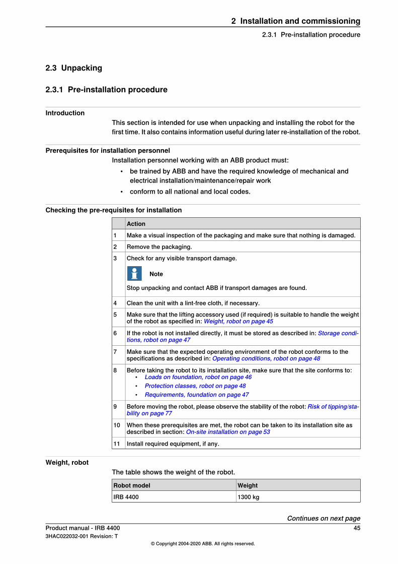
Checking the pre-requisites for installation
Action
Make a visual inspection of the packaging and make sure that nothing is damaged.1
Remove the packaging.2
Check for any visible transport damage.
Note
Stop unpacking and contact ABB if transport damages are found.
3
Clean the unit with a lint-free cloth, if necessary.4
Make sure that the lifting accessory used (if required) is suitable to handle the weightof the robot as specified in: Weight, robot on page 45
5
If the robot is not installed directly, it must be stored as described in: Storage condi-tions, robot on page 47
6
Make sure that the expected operating environment of the robot conforms to thespecifications as described in: Operating conditions, robot on page 48
7
Before taking the robot to its installation site, make sure that the site conforms to:• Loads on foundation, robot on page 46• Protection classes, robot on page 48• Requirements, foundation on page 47
8
Before moving the robot, please observe the stability of the robot: Risk of tipping/sta-bility on page 77
9
When these prerequisites are met, the robot can be taken to its installation site asdescribed in section: On-site installation on page 53
10
Install required equipment, if any.11
Weight, robotThe table shows the weight of the robot.
WeightRobot model
1300 kgIRB 4400
Continues on next pageProduct manual - IRB 4400 453HAC022032-001 Revision: T
© Copyright 2004-2020 ABB. All rights reserved.
2 Installation and commissioning2.3.1 Pre-installation procedure
Note
The weight does not include tools and other equipment fitted on the robot.
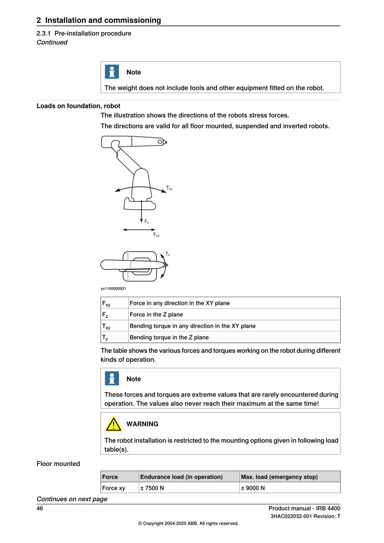
Loads on foundation, robotThe illustration shows the directions of the robots stress forces.The directions are valid for all floor mounted, suspended and inverted robots.
xy
xy
z
z
T
F
F
T
xx1100000521
Force in any direction in the XY planeFxy
Force in the Z planeFz
Bending torque in any direction in the XY planeTxy
Bending torque in the Z planeTz
The table shows the various forces and torques working on the robot during differentkinds of operation.
Note
These forces and torques are extreme values that are rarely encountered duringoperation. The values also never reach their maximum at the same time!
WARNING
The robot installation is restricted to the mounting options given in following loadtable(s).
Floor mounted
Max. load (emergency stop)Endurance load (in operation)Force
± 9000 N± 7500 NForce xy
Continues on next page46 Product manual - IRB 4400
3HAC022032-001 Revision: T© Copyright 2004-2020 ABB. All rights reserved.
2 Installation and commissioning2.3.1 Pre-installation procedureContinued
Max. load (emergency stop)Endurance load (in operation)Force
+9500 ± 3000 N+9500 ± 2000 NForce z
± 16000 Nm± 14000 NmTorque xy
± 4000 Nm± 2000 NmTorque z
Requirements, foundationThe table shows the requirements for the foundation where the weight of theinstalled robot is included:
NoteValueRequirement
Flat foundations give better repeatability of theresolver calibration compared to original settingson delivery from ABB.
0.5Flatness of foundationsurface
The value for levelness aims at the circumstanceof the anchoring points in the robot base.In order to compensate for an uneven surface,the robot can be recalibrated during installation.If resolver/encoder calibration is changed thiswill influence the absolute accuracy.
-Maximum tilt
The value is recommended for optimal perform-ance.
-
Note
It may affect themanipulator life-time to have alower resonancefrequency thanrecommended.
Minimum resonancefrequency
Due to foundation stiffness, consider robot massincluding equipment. i
For information about compensating for founda-tion flexibility, see Application manual - Control-ler software IRC5, sectionMotion ProcessMode.
i The minimum resonance frequency given should be interpreted as the frequency of the robotmass/inertia, robot assumed stiff, when a foundation translational/torsional elasticity is added, i.e.,the stiffness of the pedestal where the robot is mounted. The minimum resonance frequency shouldnot be interpreted as the resonance frequency of the building, floor etc. For example, if the equivalentmass of the floor is very high, it will not affect robot movement, even if the frequency is well belowthe stated frequency. The robot should be mounted as rigid as possibly to the floor.Disturbances from other machinery will affect the robot and the tool accuracy. The robot hasresonance frequencies in the region 10 – 20 Hz and disturbances in this region will be amplified,although somewhat damped by the servo control. This might be a problem, depending on therequirements from the applications. If this is a problem, the robot needs to be isolated from theenvironment.
Storage conditions, robotThe table shows the allowed storage conditions for the robot:
ValueParameter
-25° CMinimum ambient temperature
+55° CMaximum ambient temperature
+70° CMaximum ambient temperature (less than 24 hrs)
95% at constant temperature(gaseous only)
Maximum ambient humidity
Continues on next pageProduct manual - IRB 4400 473HAC022032-001 Revision: T
© Copyright 2004-2020 ABB. All rights reserved.
2 Installation and commissioning2.3.1 Pre-installation procedure
Continued
Operating conditions, robotThe table shows the allowed operating conditions for the robot:
ValueParameter
+5° CMinimum ambient temperature
+45° CMaximum ambient temperature
95% at constant temperatureMaximum ambient humidity
Protection classes, robotThe table shows the available protection types of the robot, with the correspondingprotection class.
Protection classProtection type
IP54Manipulator, protection type Standard
IP67, steam washableManipulator, protection type Foundry Prime
48 Product manual - IRB 44003HAC022032-001 Revision: T
© Copyright 2004-2020 ABB. All rights reserved.
2 Installation and commissioning2.3.1 Pre-installation procedureContinued
2.3.2 Working range
Introduction to robot motion
Range of movementType of motionAxis
+ 165° to - 165°Rotation motion1
+ 95° to - 70°Arm motion2
+ 65° to - 60°Arm motion3
+ 200° to - 200°Rotation motion4
+ 120° to - 120°Bend motion5
+ 400° to - 400°Turn motion6+ 200 i rev. ii to - 200 rev. Max. iii
i + 183 rev to - 183 rev valid for IRB 4400/L10ii rev. = Revolutionsiii The default working range for axis 6 can be extended by changing parameter values in the software.
Option 610-1 "Independent axis" can be used for resetting the revolution counter after the axis hasbeen rotated (no need for "rewinding" the axis).
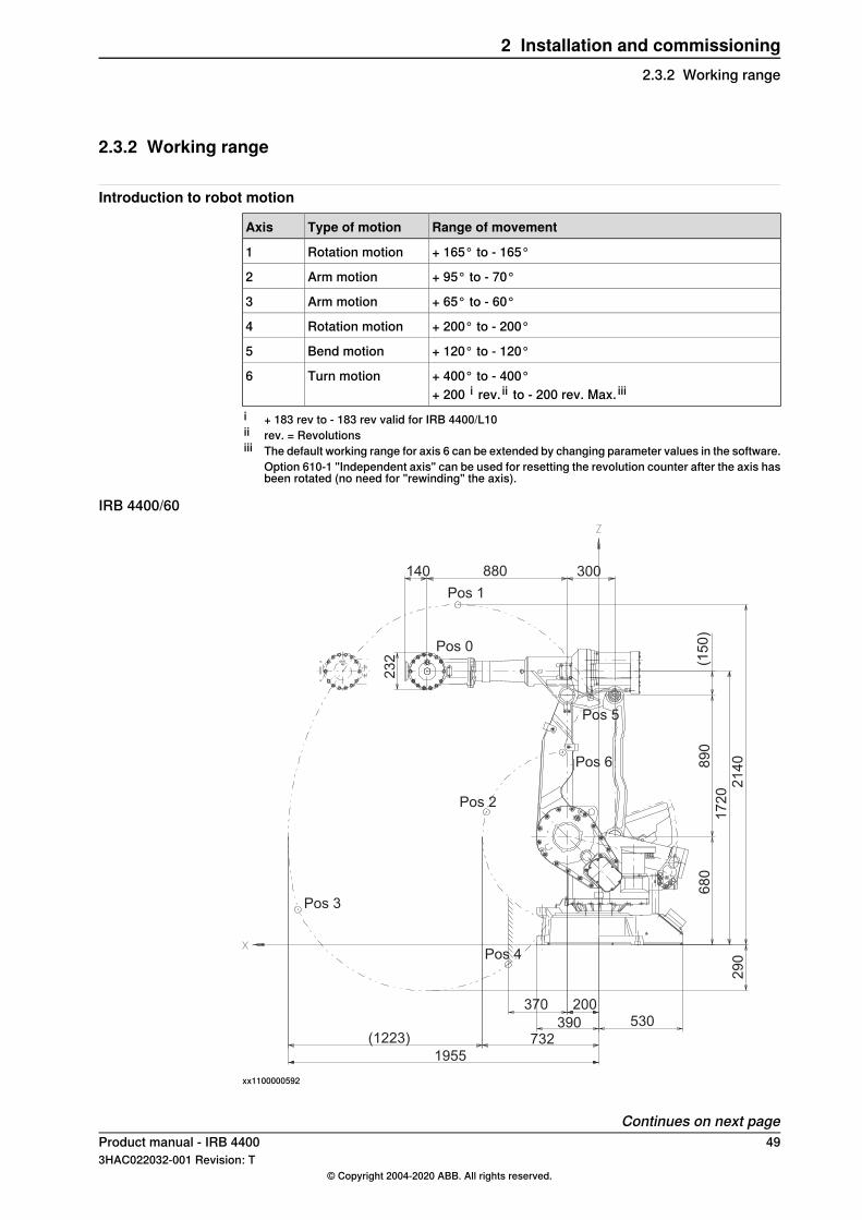
IRB 4400/60
880140 300
Pos 1
Pos 0
Pos 5
Pos 6
Pos 2
Pos 4
370 200
390 530
7321955
(1223)
29
0
68
01
72
02
14
089
0(1
50
)
Pos 3
23
2
xx1100000592
Continues on next pageProduct manual - IRB 4400 493HAC022032-001 Revision: T
© Copyright 2004-2020 ABB. All rights reserved.
2 Installation and commissioning2.3.2 Working range
Positions at wrist center (mm) and angle (degrees):
Angle (degrees)Axis 3
Angle (degrees)Axis 2
Position (mm) ZPosition (mm) XPosition no (seefigure above)
00172010800
-30021408871
6508367082
-609522118943
4095-1265704
40-701554515
65-7012102276
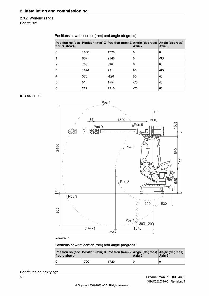
IRB 4400/L10
150085 300
Pos 1
Pos 0Pos 5
Pos 6
Pos 2
Pos 4300 200
390 530
10702547
(1477)
68
01
72
08
90
(15
0)
Pos 3
14
8
24
50
90
5
xx1300002627
Positions at wrist center (mm) and angle (degrees):
Angle (degrees)Axis 3
Angle (degrees)Axis 2
Position (mm) ZPosition (mm) XPosition no (seefigure above)
00172017000
Continues on next page50 Product manual - IRB 4400
3HAC022032-001 Revision: T© Copyright 2004-2020 ABB. All rights reserved.
2 Installation and commissioning2.3.2 Working rangeContinued
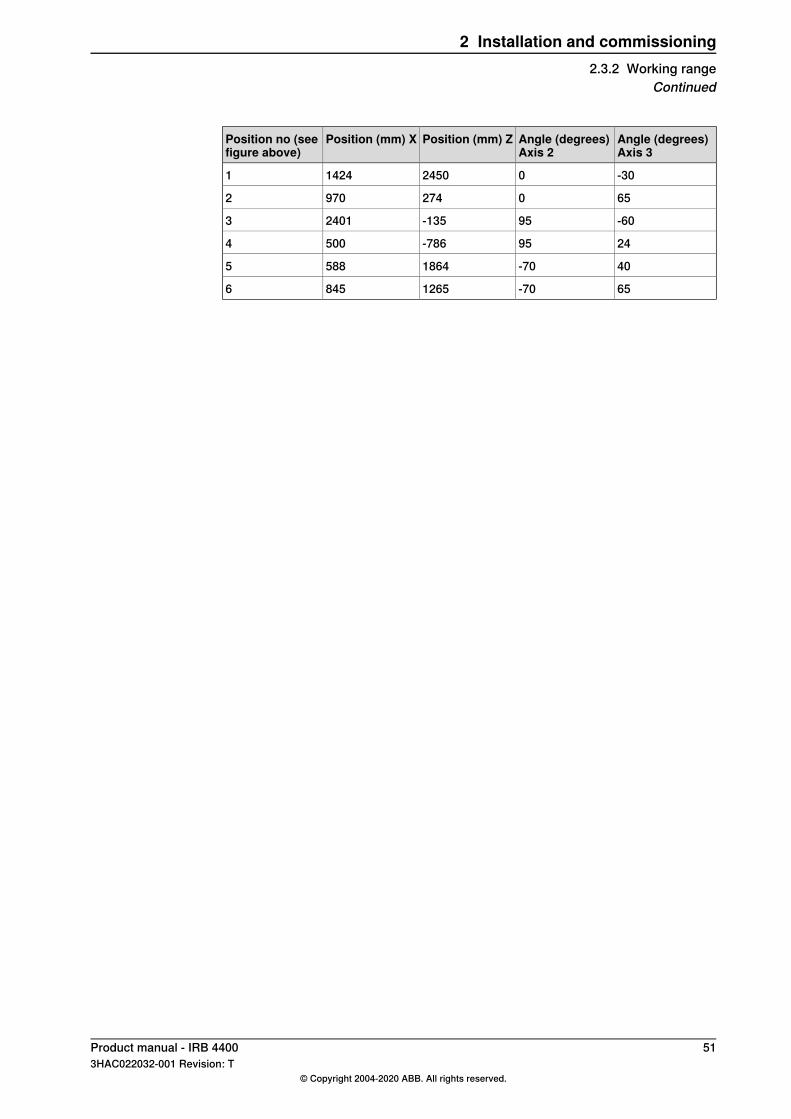
Angle (degrees)Axis 3
Angle (degrees)Axis 2
Position (mm) ZPosition (mm) XPosition no (seefigure above)
-300245014241
6502749702
-6095-13524013
2495-7865004
40-7018645885
65-7012658456
Product manual - IRB 4400 513HAC022032-001 Revision: T
© Copyright 2004-2020 ABB. All rights reserved.
2 Installation and commissioning2.3.2 Working range
Continued
2.3.3 The unit is sensitive to ESD
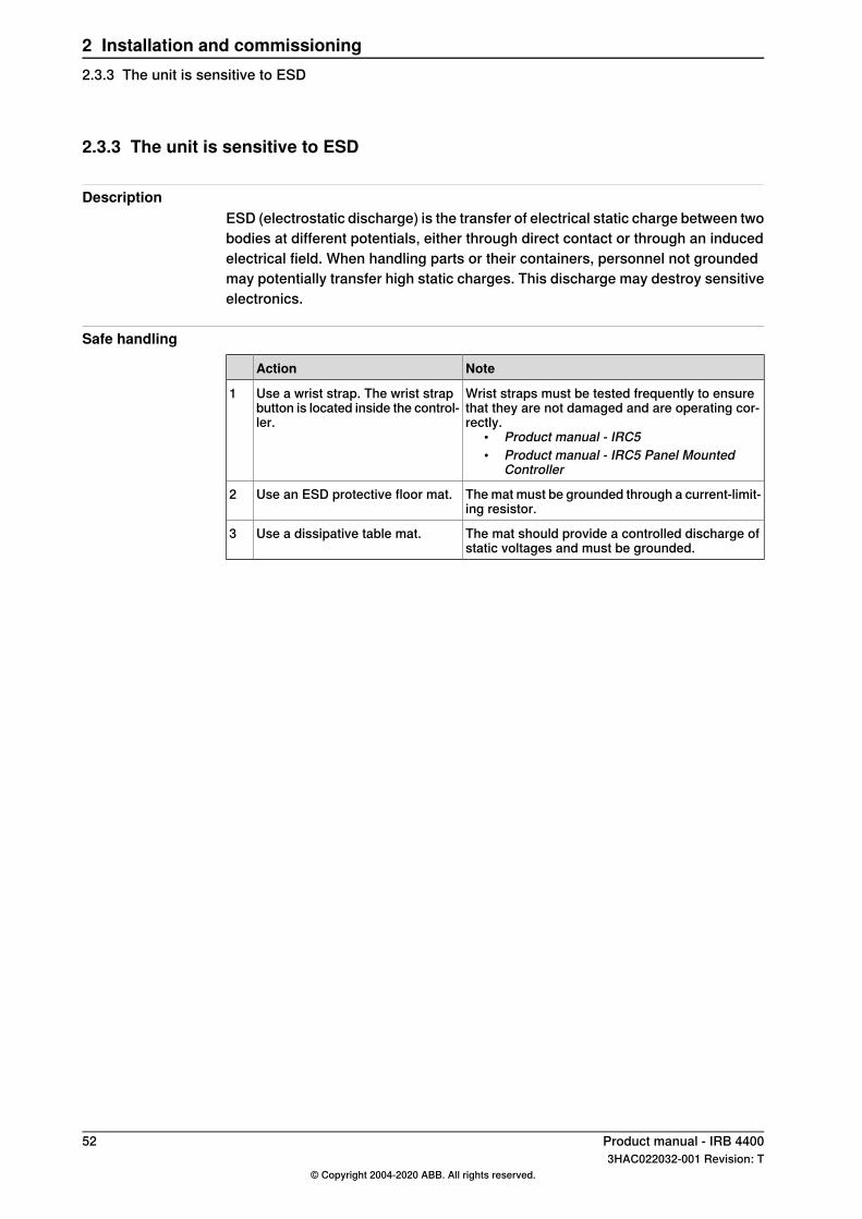
DescriptionESD (electrostatic discharge) is the transfer of electrical static charge between twobodies at different potentials, either through direct contact or through an inducedelectrical field. When handling parts or their containers, personnel not groundedmay potentially transfer high static charges. This discharge may destroy sensitiveelectronics.
Safe handling
NoteAction
Wrist straps must be tested frequently to ensurethat they are not damaged and are operating cor-rectly.
• Product manual - IRC5• Product manual - IRC5 Panel Mounted
Controller
Use a wrist strap. The wrist strapbutton is located inside the control-ler.
1
The mat must be grounded through a current-limit-ing resistor.
Use an ESD protective floor mat.2
The mat should provide a controlled discharge ofstatic voltages and must be grounded.
Use a dissipative table mat.3
52 Product manual - IRB 44003HAC022032-001 Revision: T
© Copyright 2004-2020 ABB. All rights reserved.
2 Installation and commissioning2.3.3 The unit is sensitive to ESD
2.4 On-site installation
2.4.1 Lifting robot with roundslings
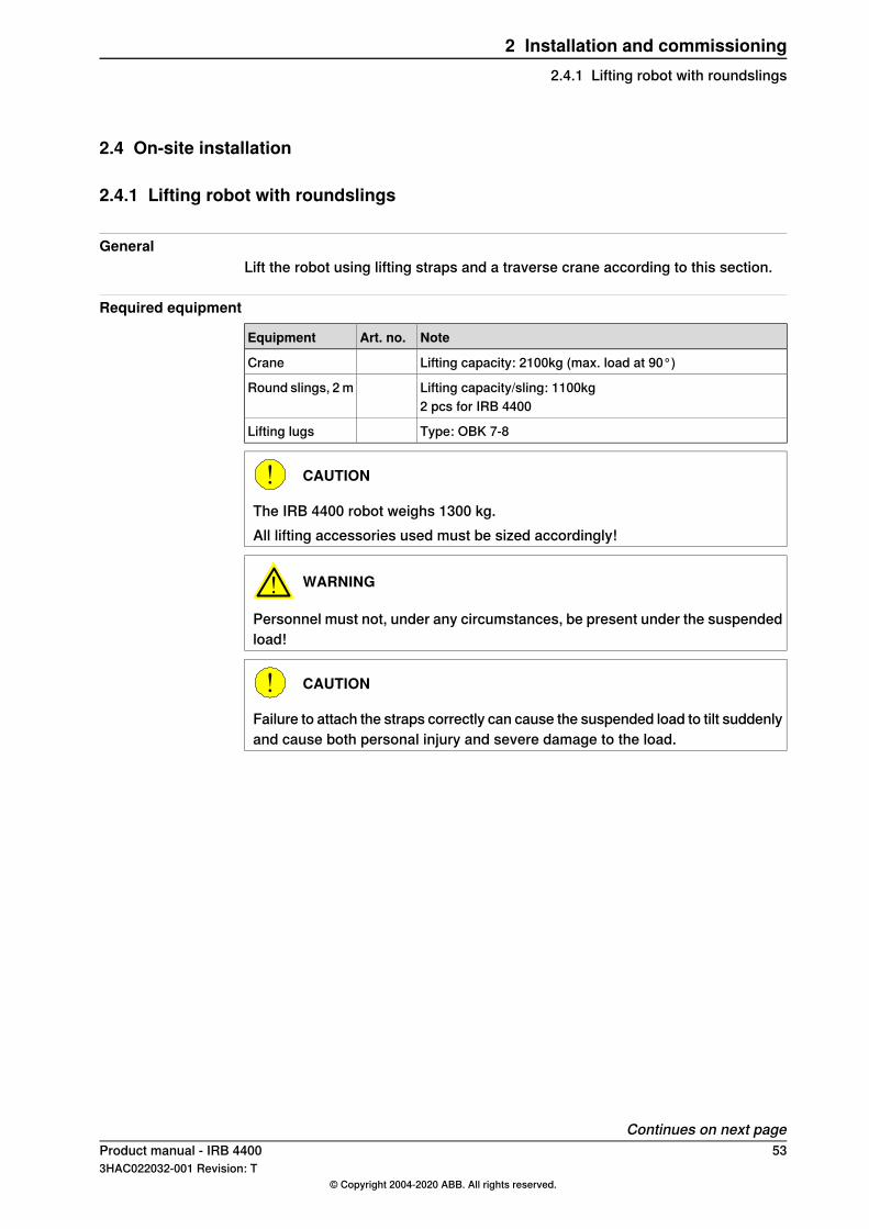
GeneralLift the robot using lifting straps and a traverse crane according to this section.
Required equipment
NoteArt. no.Equipment
Lifting capacity: 2100kg (max. load at 90°)Crane
Lifting capacity/sling: 1100kgRound slings, 2 m2 pcs for IRB 4400
Type: OBK 7-8Lifting lugs
CAUTION
The IRB 4400 robot weighs 1300 kg.All lifting accessories used must be sized accordingly!
WARNING
Personnel must not, under any circumstances, be present under the suspendedload!
CAUTION
Failure to attach the straps correctly can cause the suspended load to tilt suddenlyand cause both personal injury and severe damage to the load.
Continues on next pageProduct manual - IRB 4400 533HAC022032-001 Revision: T
© Copyright 2004-2020 ABB. All rights reserved.
2 Installation and commissioning2.4.1 Lifting robot with roundslings
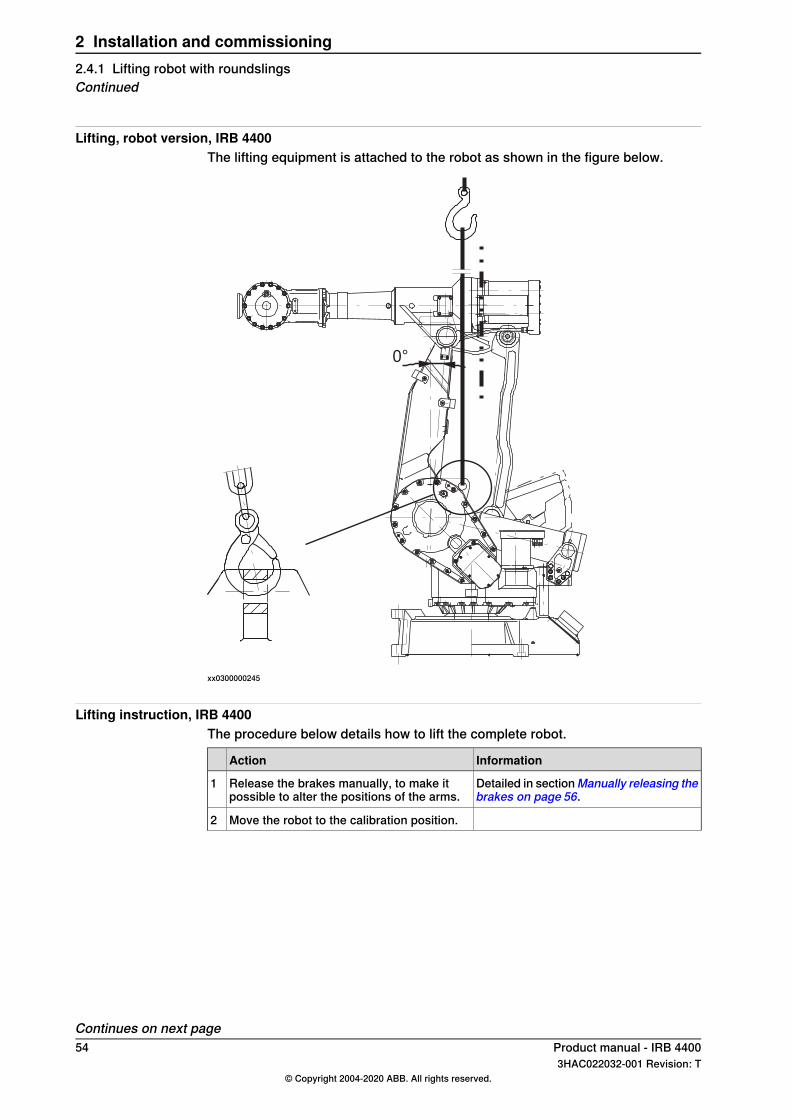
Lifting, robot version, IRB 4400The lifting equipment is attached to the robot as shown in the figure below.
0°
xx0300000245
Lifting instruction, IRB 4400The procedure below details how to lift the complete robot.
InformationAction
Detailed in sectionManually releasing thebrakes on page 56.
Release the brakes manually, to make itpossible to alter the positions of the arms.
1
Move the robot to the calibration position.2
Continues on next page54 Product manual - IRB 4400
3HAC022032-001 Revision: T© Copyright 2004-2020 ABB. All rights reserved.
2 Installation and commissioning2.4.1 Lifting robot with roundslingsContinued
InformationAction
0°
xx0300000245
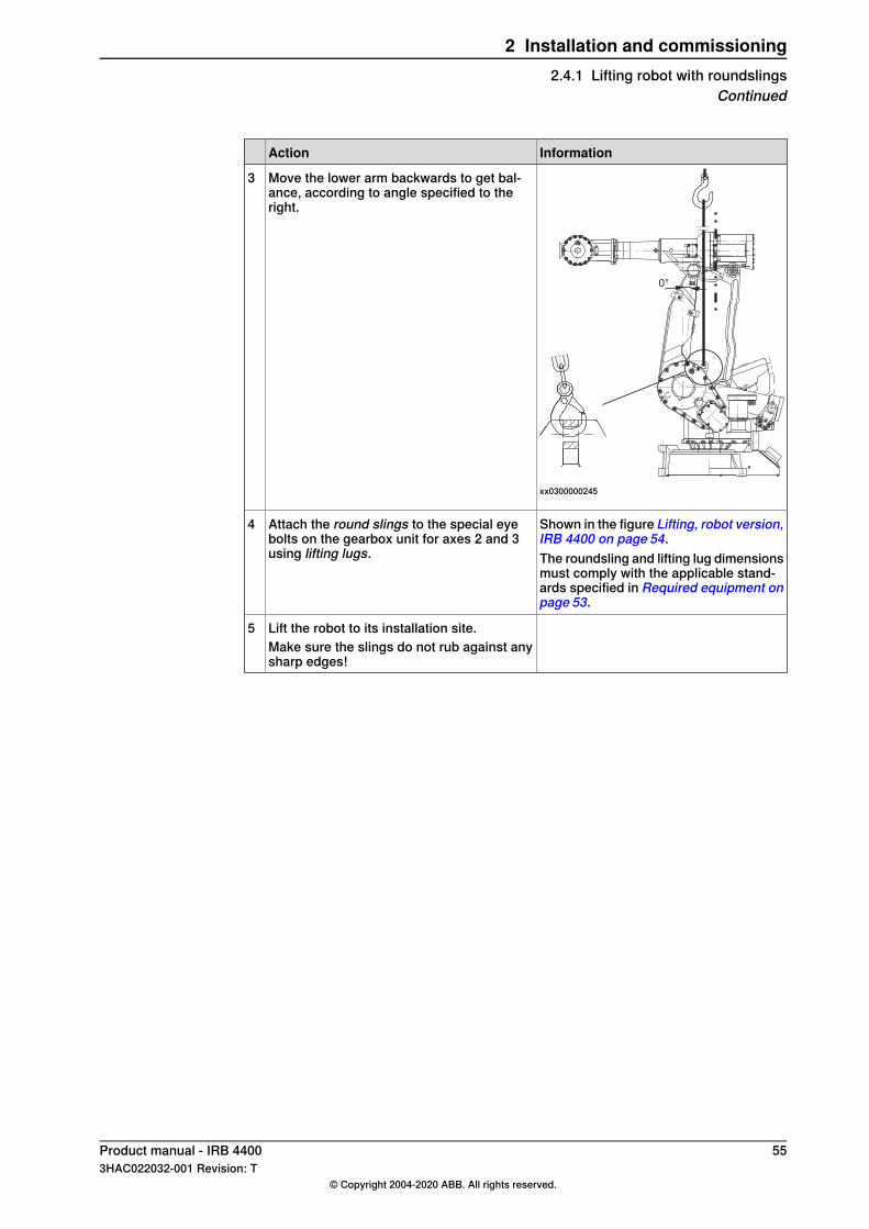
Move the lower arm backwards to get bal-ance, according to angle specified to theright.
3
Shown in the figure Lifting, robot version,IRB 4400 on page 54.
Attach the round slings to the special eyebolts on the gearbox unit for axes 2 and 3using lifting lugs.
4
The roundsling and lifting lug dimensionsmust comply with the applicable stand-ards specified in Required equipment onpage 53.
Lift the robot to its installation site.5Make sure the slings do not rub against anysharp edges!
Product manual - IRB 4400 553HAC022032-001 Revision: T
© Copyright 2004-2020 ABB. All rights reserved.
2 Installation and commissioning2.4.1 Lifting robot with roundslings
Continued
2.4.2 Manually releasing the brakes
GeneralThe section below describes how to release the holding brakes of each axis' motor.This can be done in one of three ways:
• using the push-button when the robot is connected to the controller.• using the push-button on the robot with an external power supply.• using an external voltage supply directly on the respective brake.
DANGER
When releasing the holding brakes with push-buttons, the robot must be properlyattached!
DANGER
When releasing the holding brakes, the robot axes may move very quickly andsometimes in unexpected ways!Make sure no personnel is near or beneath the robot arm!
Using the push-button when the robot is connected to the controllerThis procedure details how to release the holding brakes with push-buttons, whenthe robot is connected to the controller.
NoteAction
xx0300000198
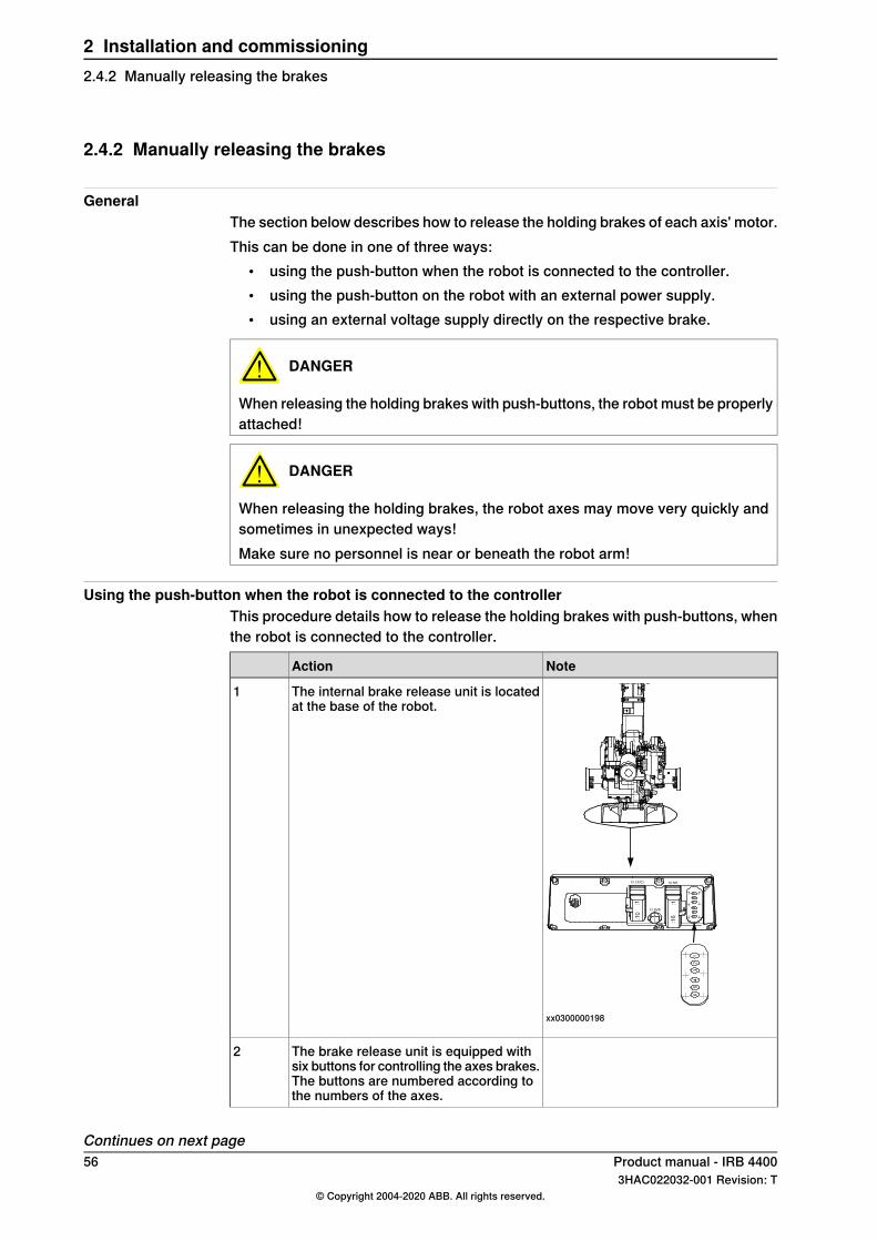
The internal brake release unit is locatedat the base of the robot.
1
The brake release unit is equipped withsix buttons for controlling the axes brakes.The buttons are numbered according tothe numbers of the axes.
2
Continues on next page56 Product manual - IRB 4400
3HAC022032-001 Revision: T© Copyright 2004-2020 ABB. All rights reserved.
2 Installation and commissioning2.4.2 Manually releasing the brakes
NoteAction
Release the holding brake on a particularaxis by pressing the corresponding buttonon the push-button unit and keeping itdepressed.
3
The brake will function again as soon asthe button is released.
4
Using the push-button on the robot with an external power supplyThis procedure details how to release the holding brakes with the push-buttons,when the robot is not connected to the controller.
NoteAction
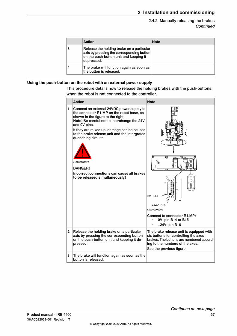
xx0300000200
Connect an external 24VDC power supply tothe connector R1.MP on the robot base, asshown in the figure to the right.Note! Be careful not to interchange the 24Vand 0V pins.If they are mixed up, damage can be causedto the brake release unit and the intergratedquenching circuits.
xx0200000022
DANGER!Incorrect connections can cause all brakesto be released simultaneously!
1
Connect to connector R1.MP:• 0V: pin B14 or B15• +24V: pin B16
The brake release unit is equipped withsix buttons for controlling the axesbrakes. The buttons are numbered accord-ing to the numbers of the axes.
Release the holding brake on a particularaxis by pressing the corresponding buttonon the push-button unit and keeping it de-pressed.
2
See the previous figure.
The brake will function again as soon as thebutton is released.
3
Continues on next pageProduct manual - IRB 4400 573HAC022032-001 Revision: T
© Copyright 2004-2020 ABB. All rights reserved.
2 Installation and commissioning2.4.2 Manually releasing the brakes
Continued
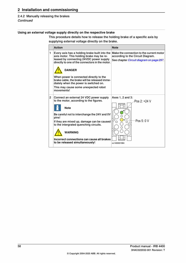
Using an external voltage supply directly on the respective brakeThis procedure details how to release the holding brake of a specific axis bysupplying external voltage directly on the brake.
NoteAction
Make the connection to the current motoraccording to the Circuit Diagram.
Every axis has a holding brake built into theaxis motor. This holding brake may be re-leased by connecting 24VDC power supplydirectly to one of the connectors in the motor.
DANGER
When power is connected directly to thebrake cable, the brake will be released imme-diately when the power is switched on.This may cause some unexpected robotmovements!
1
See chapterCircuit diagram on page297.
Axes 1, 2 and 3:Pos 2: +24 V
Pos 5: 0 V
xx1400001984
Connect an external 24 VDC power supplyto the motor, according to the figures.
Note
Be careful not to interchange the 24V and 0Vpins!If they are mixed up, damage can be causedto the intergrated quenching circuits.
WARNING
Incorrect connections can cause all brakesto be released simultaneously!
2
58 Product manual - IRB 44003HAC022032-001 Revision: T
© Copyright 2004-2020 ABB. All rights reserved.
2 Installation and commissioning2.4.2 Manually releasing the brakesContinued
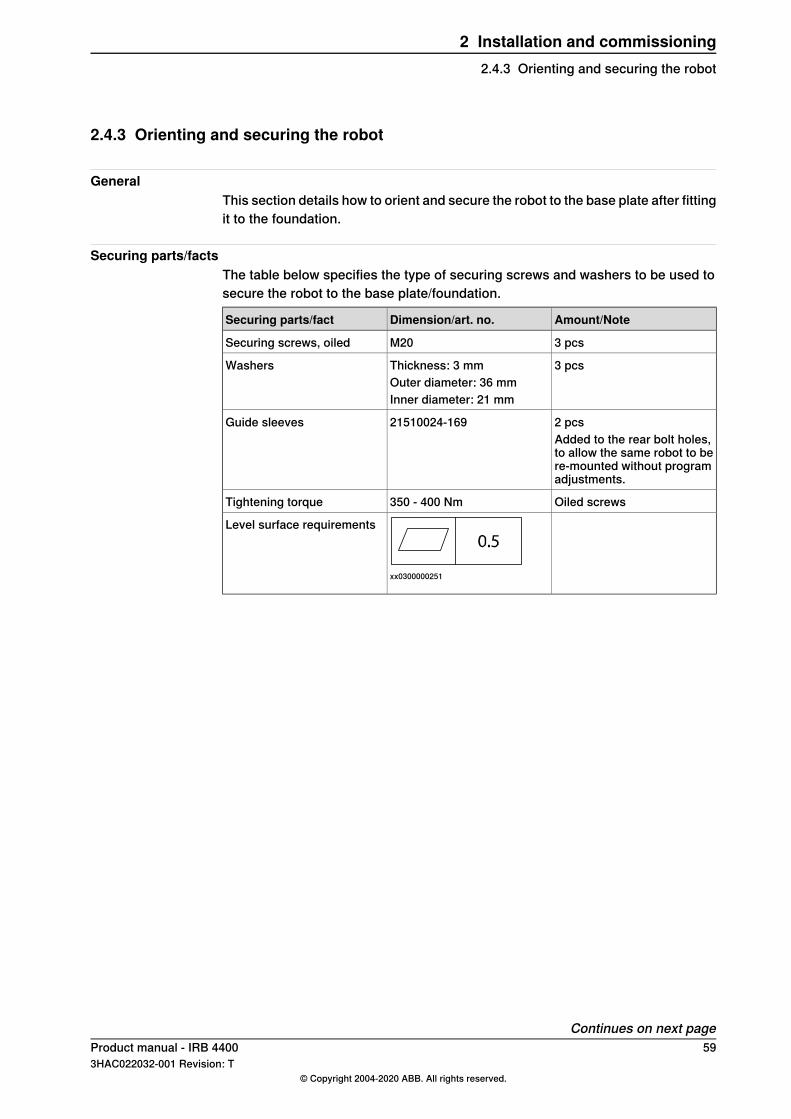
2.4.3 Orienting and securing the robot
GeneralThis section details how to orient and secure the robot to the base plate after fittingit to the foundation.
Securing parts/factsThe table below specifies the type of securing screws and washers to be used tosecure the robot to the base plate/foundation.
Amount/NoteDimension/art. no.Securing parts/fact
3 pcsM20Securing screws, oiled
3 pcsThickness: 3 mmWashersOuter diameter: 36 mmInner diameter: 21 mm
2 pcs21510024-169Guide sleevesAdded to the rear bolt holes,to allow the same robot to bere-mounted without programadjustments.
Oiled screws350 - 400 NmTightening torque
xx0300000251
Level surface requirements
Continues on next pageProduct manual - IRB 4400 593HAC022032-001 Revision: T
© Copyright 2004-2020 ABB. All rights reserved.
2 Installation and commissioning2.4.3 Orienting and securing the robot

Hole configuration and dimensionsThe illustration below shows the hole configuration and hole dimensions of therobot base, seen from below.The cut x-x shows the dimension of the rear bolt holes, where the guide sleevesmay be used.
xx0300000252
Rear bolt holesA
Center line, axis 1B
Orienting and securing the robotThe procedure below details how to orient and secure the robot to the base plateafter fitting the plate to the foundation.
Info/IllustrationAction
WARNING
When the robot is put down, before attach-ment to the floor is done, the risk of tippingis big, if not properly secured.
1
CAUTION
The IRB 4400 robot weighs 1300 kg.All lifting accessories used must be sizedaccordingly!
2
Detailed in section Lifting robot withroundslings on page 53.
Lift the robot.3
Move the robot to the vicinity of the installa-tion site.
4
Continues on next page60 Product manual - IRB 4400
3HAC022032-001 Revision: T© Copyright 2004-2020 ABB. All rights reserved.
2 Installation and commissioning2.4.3 Orienting and securing the robotContinued
Info/IllustrationAction
Art. no. is specified inSecuring parts/factson page 59.
Fit two guide sleeves to the rear bolt holesin the base.
5
Shown in the figure Hole configurationand dimensions on page 60.
Guide the robot gently using M20 screwswhile lowering it into its mounting position.
6
Specified in Securing parts/facts onpage 59.
Fit the securing screws and washers in thebase attachment holes.
7
Attachment holes shown in the figureHole configuration and dimensions onpage 60.
When bolting a mounting plate or frame to aconcrete floor, follow the general instructionsfor expansion-shell bolts.
8
The screw joint must be able to withstand thestress loads defined in section Loads onfoundation, robot on page 46.
Product manual - IRB 4400 613HAC022032-001 Revision: T
© Copyright 2004-2020 ABB. All rights reserved.
2 Installation and commissioning2.4.3 Orienting and securing the robot
Continued
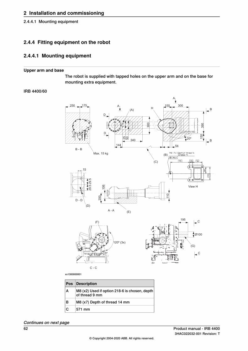
2.4.4 Fitting equipment on the robot
2.4.4.1 Mounting equipment
Upper arm and baseThe robot is supplied with tapped holes on the upper arm and on the base formounting extra equipment.
IRB 4400/60
15º
120º (3x)
C - C
(F)195
Ø100
(G)
C
C
(D)
D - D
29
.5
15
29
.5
25
50
144
340
30
054
20º
39
01
50
300150
B
B
A
A
D
D
(A)
(C)
Max. 15 kg
250 175
B - B
View H
H
(B)
10
6
20
0 11
0
A - A (E)
xx1300000001
DescriptionPos
M8 (x2) Used if option 218-6 is chosen, depthof thread 9 mm
A
M8 (x7) Depth of thread 14 mmB
571 mmC
Continues on next page62 Product manual - IRB 4400
3HAC022032-001 Revision: T© Copyright 2004-2020 ABB. All rights reserved.
2 Installation and commissioning2.4.4.1 Mounting equipment
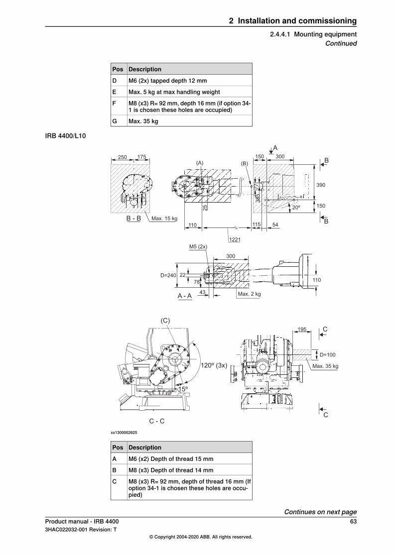
DescriptionPos
M6 (2x) tapped depth 12 mmD
Max. 5 kg at max handling weightE
M8 (x3) R= 92 mm, depth 16 mm (if option 34-1 is chosen these holes are occupied)
F
Max. 35 kgG
IRB 4400/L10
.
250 175(A) (B)
150 300
A
B - B Max. 15 kg
110
1221
115 54
20º 150
390
B
B
38
57
7
25
110
Max. 2 kg
300
M5 (2x)
D=240 22
78
43A - A
195
D=100
Max. 35 kg
C
C
15º
120º (3x)
C - C
(C)
xx1300002625
DescriptionPos
M6 (x2) Depth of thread 15 mmA
M8 (x3) Depth of thread 14 mmB
M8 (x3) R= 92 mm, depth of thread 16 mm (Ifoption 34-1 is chosen these holes are occu-pied)
C
Continues on next pageProduct manual - IRB 4400 633HAC022032-001 Revision: T
© Copyright 2004-2020 ABB. All rights reserved.
2 Installation and commissioning2.4.4.1 Mounting equipment
Continued
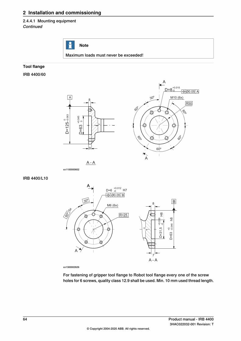
Note
Maximum loads must never be exceeded!
Tool flange
IRB 4400/60
-
A
D=8+0.015
-0 Ø0.05 A
M10 (6x)
R50
60º
60º
60º
60º
60º30º
A
A8
9
A - A
D=
12
5 0 -0
.06
3
D=
63
+0
.04
5
0
xx1100000602
IRB 4400/L10
B8
7
D=
63
+0
-0.0
46
h8
D=
31
,5+
0.0
39
-0H
8
A - A
AD=6
+0.012
-0 H7
Ø0.05 B
M6 (6x)
R=25
30º
60º 5
x
A
A
xx1300002626
For fastening of gripper tool flange to Robot tool flange every one of the screwholes for 6 screws, quality class 12.9 shall be used. Min. 10 mm used thread length.
64 Product manual - IRB 44003HAC022032-001 Revision: T
© Copyright 2004-2020 ABB. All rights reserved.
2 Installation and commissioning2.4.4.1 Mounting equipmentContinued
2.4.5 Loads fitted to the robot, stopping time and braking distances
GeneralAny loads mounted on the robot must be defined correctly and carefully (withregard to the position of center of gravity and mass moments of inertia) in orderto avoid jolting movements and overloading motors, gears and structure.
CAUTION
Incorrectly defined loads may result in operational stops or major damage to therobot.
ReferencesLoad diagrams, permitted extra loads (equipment) and their positions are specifiedin the product specification. The loads must be defined in the software.
• User’s guide - S4Cplus (BaseWare OS 4.0)• Operating manual - IRC5 with FlexPendant
Stopping time and braking distancesThe performance of the motor brake depends on if there are any loads attachedto the robot. For more information, see product specification for the robot.
Product manual - IRB 4400 653HAC022032-001 Revision: T
© Copyright 2004-2020 ABB. All rights reserved.
2 Installation and commissioning2.4.5 Loads fitted to the robot, stopping time and braking distances
2.5 Restricting the working range
2.5.1 Axes with restricted working range
GeneralWhen installing the robot, make sure that it can move freely within its entire workingspace. If there is a risk that it may collide with other objects, its working spaceshould be limited.The working range of the following axes may be restricted:
• Axis 1, hardware (mechanical stop) and software (signal from adjustableposition switch)
• Axis 2, hardware (mechanical stop)• Axis 3, software (signal from limit switch)
This section describes how to install hardware that restricts the working range.
Note
Adjustments must also be made in the robot configuration software (systemparameters). References to relevant manuals are included in the installationprocedures.
66 Product manual - IRB 44003HAC022032-001 Revision: T
© Copyright 2004-2020 ABB. All rights reserved.
2 Installation and commissioning2.5.1 Axes with restricted working range
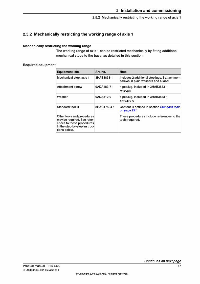
2.5.2 Mechanically restricting the working range of axis 1
Mechanically restricting the working rangeThe working range of axis 1 can be restricted mechanically by fitting additionalmechanical stops to the base, as detailed in this section.
Required equipment
NoteArt. no.Equipment, etc.
Includes 2 additional stop lugs, 8 attachmentscrews, 8 plain washers and a label
3HAB3833-1Mechanical stop, axis 1
4 pcs/lug, included in 3HAB3833-19ADA183-71Attachment screwM12x60
4 pcs/lug, included in 3HAB3833-19ADA312-9Washer13x24x2.5
Content is defined in section Standard toolson page 291.
3HAC17594-1Standard toolkit
These procedures include references to thetools required.
Other tools and proceduresmay be required. See refer-ences to these proceduresin the step-by-step instruc-tions below.
Continues on next pageProduct manual - IRB 4400 673HAC022032-001 Revision: T
© Copyright 2004-2020 ABB. All rights reserved.
2 Installation and commissioning2.5.2 Mechanically restricting the working range of axis 1
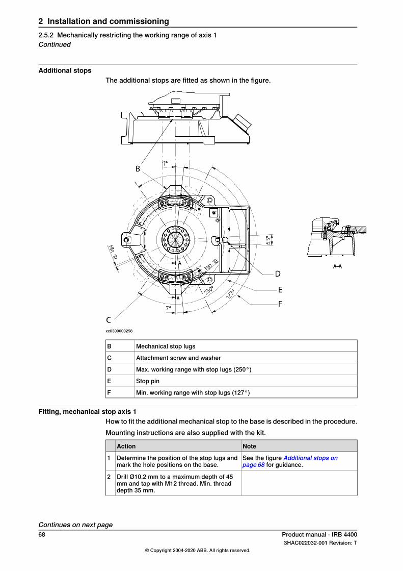
Additional stopsThe additional stops are fitted as shown in the figure.
xx0300000258
Mechanical stop lugsB
Attachment screw and washerC
Max. working range with stop lugs (250°)D
Stop pinE
Min. working range with stop lugs (127°)F
Fitting, mechanical stop axis 1How to fit the additional mechanical stop to the base is described in the procedure.Mounting instructions are also supplied with the kit.
NoteAction
See the figure Additional stops onpage 68 for guidance.
Determine the position of the stop lugs andmark the hole positions on the base.
1
Drill Ø10.2 mm to a maximum depth of 45mm and tap with M12 thread. Min. threaddepth 35 mm.
2
Continues on next page68 Product manual - IRB 4400
3HAC022032-001 Revision: T© Copyright 2004-2020 ABB. All rights reserved.
2 Installation and commissioning2.5.2 Mechanically restricting the working range of axis 1Continued
NoteAction
Specified in Required equipment onpage 67.
Fit the stop lugs firmly with attachmentscrews and washers according to the figureAdditional stops on page 68.
3
M12x60, tightening torque: 82 Nm, oillubrication.
Product manual - IRB 4400 693HAC022032-001 Revision: T
© Copyright 2004-2020 ABB. All rights reserved.
2 Installation and commissioning2.5.2 Mechanically restricting the working range of axis 1
Continued
2.5.3 Mechanically restricting the working range of axis 2
Mechanically restricting the working rangeThe working range of axis 2 can be restricted mechanically by fitting additionalmechanical stops (spacers and dampers) to the lower arm and gearbox unit axis1-3, as detailed in this section. Note that the system parameter configuration mustalso be adjusted (Upper joint bound and Lower joint bound for the type Arm in thetopic Motion).
Required equipment
NoteArt. no.Spare part no.Equipment, etc.
Includes spacers, dampers,attachment screws and nuts.
3HAC4225-1Mechanical stop, axis 2
3HAB9185-1Spacer (damper)
3HAC3962-1Spacer
Content is defined in sectionContents, standard toolkit onpage 291.
3HAC17594-1Standard toolkit
These procedures includereferences to the tools re-quired.
Other tools and proceduresmay be required. See refer-ences to these proceduresin the step-by-step instruc-tions below.
Continues on next page70 Product manual - IRB 4400
3HAC022032-001 Revision: T© Copyright 2004-2020 ABB. All rights reserved.
2 Installation and commissioning2.5.3 Mechanically restricting the working range of axis 2
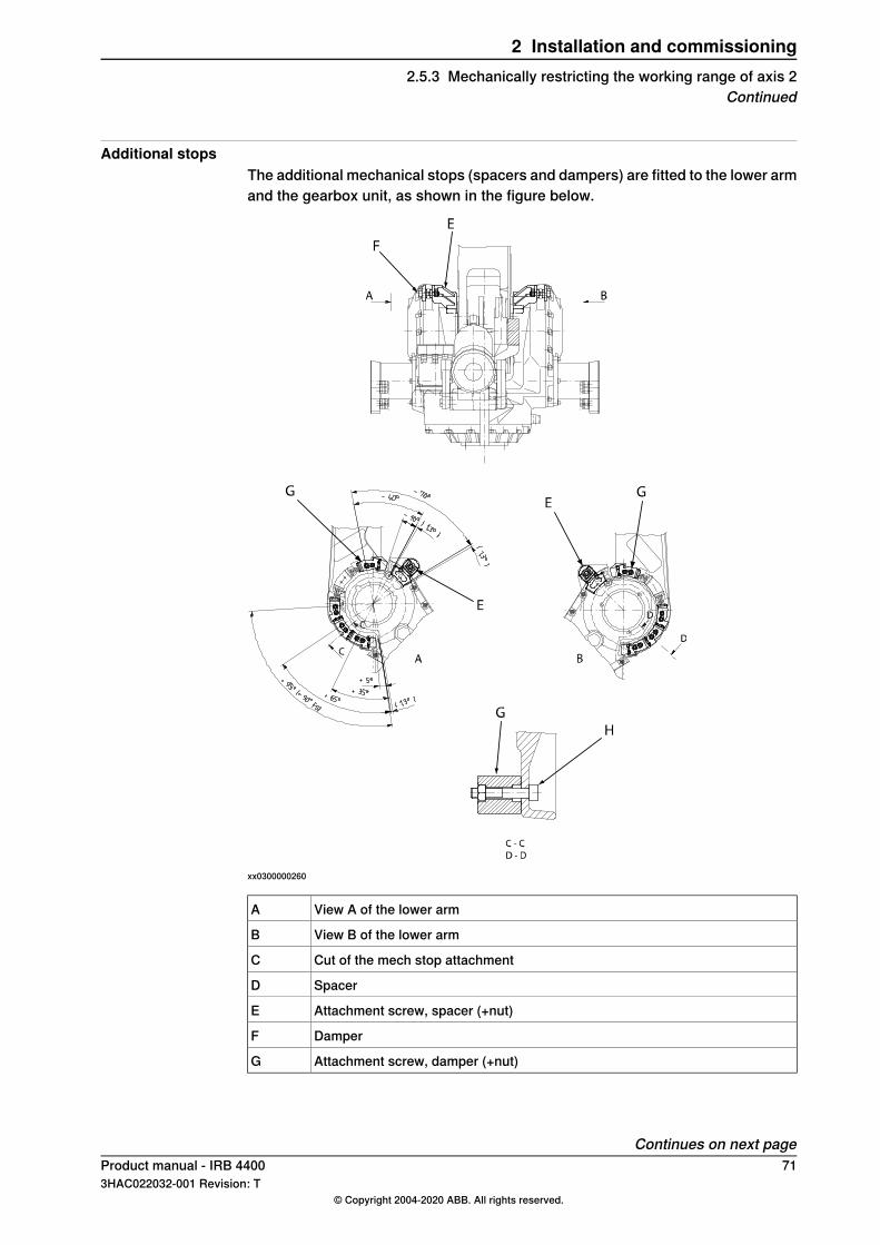
Additional stopsThe additional mechanical stops (spacers and dampers) are fitted to the lower armand the gearbox unit, as shown in the figure below.
xx0300000260
View A of the lower armA
View B of the lower armB
Cut of the mech stop attachmentC
SpacerD
Attachment screw, spacer (+nut)E
DamperF
Attachment screw, damper (+nut)G
Continues on next pageProduct manual - IRB 4400 713HAC022032-001 Revision: T
© Copyright 2004-2020 ABB. All rights reserved.
2 Installation and commissioning2.5.3 Mechanically restricting the working range of axis 2
Continued
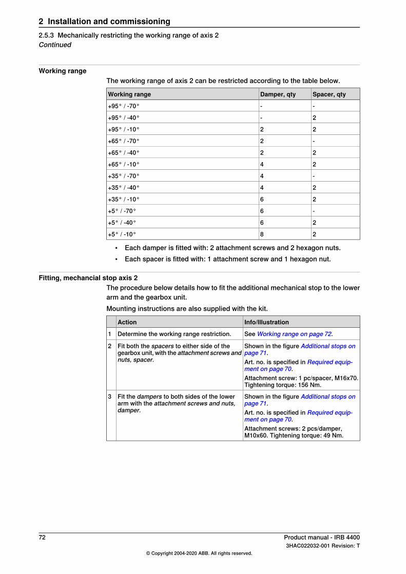
Working rangeThe working range of axis 2 can be restricted according to the table below.
Spacer, qtyDamper, qtyWorking range
--+95° / -70°
2-+95° / -40°
22+95° / -10°
-2+65° / -70°
22+65° / -40°
24+65° / -10°
-4+35° / -70°
24+35° / -40°
26+35° / -10°
-6+5° / -70°
26+5° / -40°
28+5° / -10°
• Each damper is fitted with: 2 attachment screws and 2 hexagon nuts.• Each spacer is fitted with: 1 attachment screw and 1 hexagon nut.
Fitting, mechancial stop axis 2The procedure below details how to fit the additional mechanical stop to the lowerarm and the gearbox unit.Mounting instructions are also supplied with the kit.
Info/IllustrationAction
See Working range on page 72.Determine the working range restriction.1
Shown in the figure Additional stops onpage 71.
Fit both the spacers to either side of thegearbox unit, with the attachment screws andnuts, spacer.
2
Art. no. is specified in Required equip-ment on page 70.Attachment screw: 1 pc/spacer, M16x70.Tightening torque: 156 Nm.
Shown in the figure Additional stops onpage 71.
Fit the dampers to both sides of the lowerarm with the attachment screws and nuts,damper.
3
Art. no. is specified in Required equip-ment on page 70.Attachment screws: 2 pcs/damper,M10x60. Tightening torque: 49 Nm.
72 Product manual - IRB 44003HAC022032-001 Revision: T
© Copyright 2004-2020 ABB. All rights reserved.
2 Installation and commissioning2.5.3 Mechanically restricting the working range of axis 2Continued
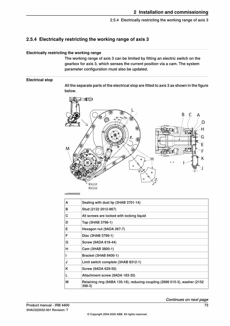
2.5.4 Electrically restricting the working range of axis 3
Electrically restricting the working rangeThe working range of axis 3 can be limited by fitting an electric switch on thegearbox for axis 3, which senses the current position via a cam. The systemparameter configuration must also be updated.
Electrical stopAll the separate parts of the electrical stop are fitted to axis 3 as shown in the figurebelow.
xx0300000262
Sealing with dust lip (3HAB 3701-14)A
Stud (2122 2012-867)B
All screws are locked with locking liquidC
Tap (3HAB 3798-1)D
Hexagon nut (9ADA 267-7)E
Disc (3HAB 3799-1)F
Screw (9ADA 618-44)G
Cam (3HAB 3800-1)H
Bracket (3HAB 8400-1)I
Limit switch complete (3HAB 8312-1)J
Screw (9ADA 629-50)K
Attachment screw (9ADA 183-35)L
Retaining ring (9ABA 135-18), reducing coupling (2686 015-3), washer (2152398-3)
M
Continues on next pageProduct manual - IRB 4400 733HAC022032-001 Revision: T
© Copyright 2004-2020 ABB. All rights reserved.
2 Installation and commissioning2.5.4 Electrically restricting the working range of axis 3
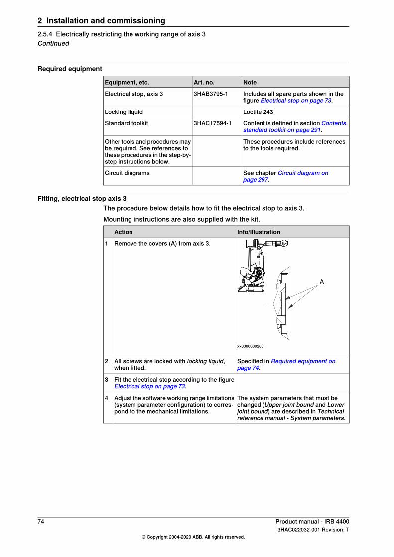
Required equipment
NoteArt. no.Equipment, etc.
Includes all spare parts shown in thefigure Electrical stop on page 73.
3HAB3795-1Electrical stop, axis 3
Loctite 243Locking liquid
Content is defined in sectionContents,standard toolkit on page 291.
3HAC17594-1Standard toolkit
These procedures include referencesto the tools required.
Other tools and procedures maybe required. See references tothese procedures in the step-by-step instructions below.
See chapter Circuit diagram onpage 297.
Circuit diagrams
Fitting, electrical stop axis 3The procedure below details how to fit the electrical stop to axis 3.Mounting instructions are also supplied with the kit.
Info/IllustrationAction
xx0300000263
Remove the covers (A) from axis 3.1
Specified in Required equipment onpage 74.
All screws are locked with locking liquid,when fitted.
2
Fit the electrical stop according to the figureElectrical stop on page 73.
3
The system parameters that must bechanged (Upper joint bound and Lowerjoint bound) are described in Technicalreference manual - System parameters.
Adjust the software working range limitations(system parameter configuration) to corres-pond to the mechanical limitations.
4
74 Product manual - IRB 44003HAC022032-001 Revision: T
© Copyright 2004-2020 ABB. All rights reserved.
2 Installation and commissioning2.5.4 Electrically restricting the working range of axis 3Continued
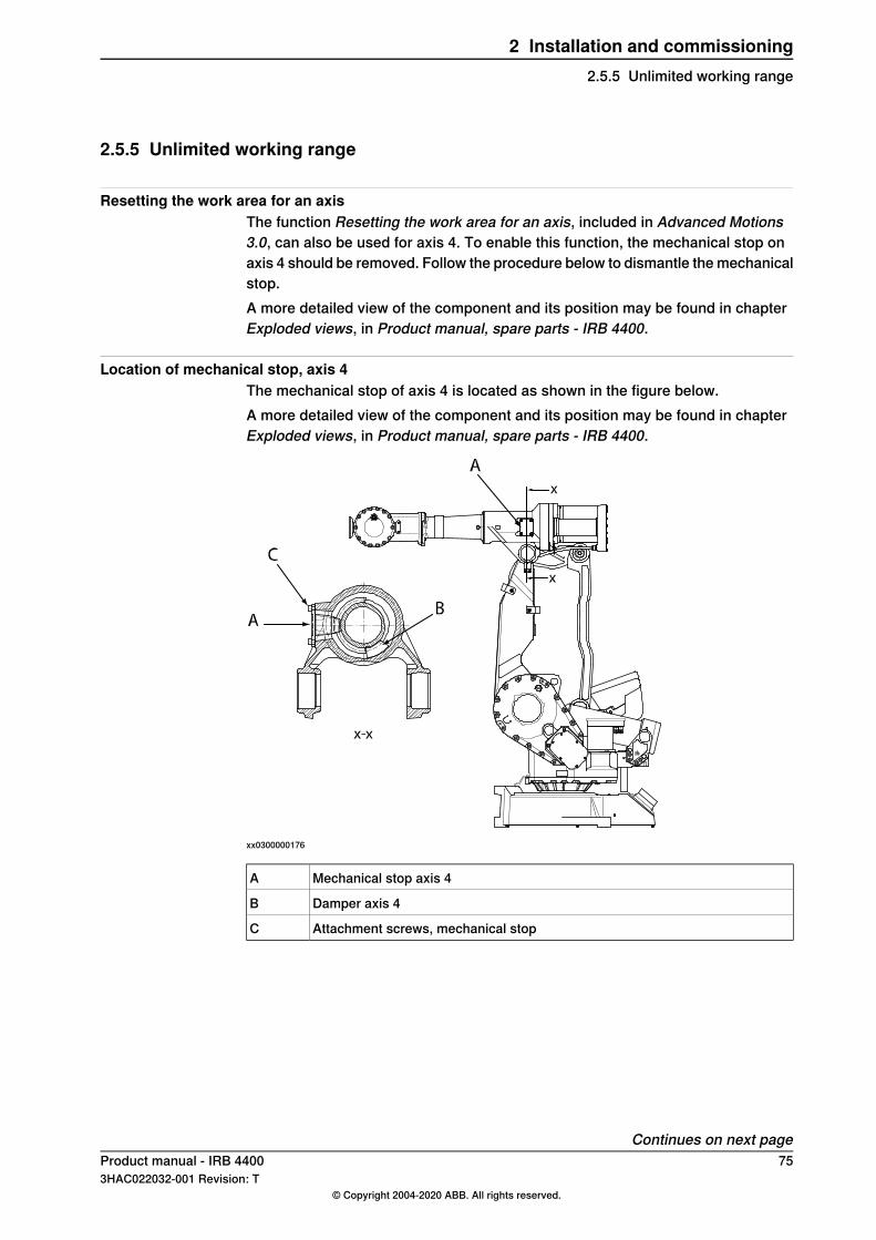
2.5.5 Unlimited working range
Resetting the work area for an axisThe function Resetting the work area for an axis, included in Advanced Motions3.0, can also be used for axis 4. To enable this function, the mechanical stop onaxis 4 should be removed. Follow the procedure below to dismantle the mechanicalstop.A more detailed view of the component and its position may be found in chapterExploded views, in Product manual, spare parts - IRB 4400.
Location of mechanical stop, axis 4The mechanical stop of axis 4 is located as shown in the figure below.A more detailed view of the component and its position may be found in chapterExploded views, in Product manual, spare parts - IRB 4400.
xx0300000176
Mechanical stop axis 4A
Damper axis 4B
Attachment screws, mechanical stopC
Continues on next pageProduct manual - IRB 4400 753HAC022032-001 Revision: T
© Copyright 2004-2020 ABB. All rights reserved.
2 Installation and commissioning2.5.5 Unlimited working range
Removal of mechanical stop, axis 4The procedure below details how to remove the mechanical stop of axis 4, to enablethe function Resetting the work area for an axis.
WARNING
When the damper is removed from axis 4, the axis does not have a mechanicalstop! If the robot is provided with cabling on the upper arm, the cabling can bedamaged when the function Resetting the work area for an axis is used, or if therobot is jogged uncalibrated.
Info/IllustrationAction
DANGER
Turn off all:• electric power supply• hydraulic pressure supply• air pressure supply (do not turn off for
Foundry Prime robots!)to the robot, before entering the robot work-ing area.
1
Shown in the figure Location of mechan-ical stop, axis 4 on page 75.
Loosen the attachment screws, mech stopand remove the mechanical stop, axis 4.
2
Slowly rotate axis 4 until the damper is visiblethrough the hole.
3
Remove the damper.4
4 pcs, M8x16. Tightening torque: 24 Nm.Refit the mechanical stop to the axis 4 withits attachment screws.
5
76 Product manual - IRB 44003HAC022032-001 Revision: T
© Copyright 2004-2020 ABB. All rights reserved.
2 Installation and commissioning2.5.5 Unlimited working rangeContinued
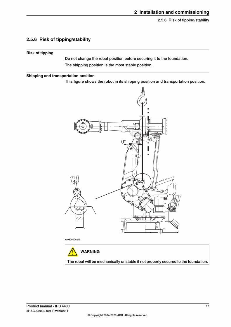
2.5.6 Risk of tipping/stability
Risk of tippingDo not change the robot position before securing it to the foundation.The shipping position is the most stable position.
Shipping and transportation positionThis figure shows the robot in its shipping position and transportation position.
0°
xx0300000245
WARNING
The robot will be mechanically unstable if not properly secured to the foundation.
Product manual - IRB 4400 773HAC022032-001 Revision: T
© Copyright 2004-2020 ABB. All rights reserved.
2 Installation and commissioning2.5.6 Risk of tipping/stability
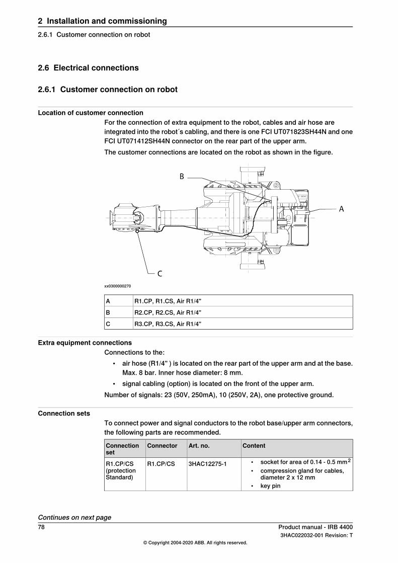
2.6 Electrical connections
2.6.1 Customer connection on robot
Location of customer connectionFor the connection of extra equipment to the robot, cables and air hose areintegrated into the robot´s cabling, and there is one FCI UT071823SH44N and oneFCI UT071412SH44N connector on the rear part of the upper arm.The customer connections are located on the robot as shown in the figure.
xx0300000270
R1.CP, R1.CS, Air R1/4"A
R2.CP, R2.CS, Air R1/4"B
R3.CP, R3.CS, Air R1/4"C
Extra equipment connectionsConnections to the:
• air hose (R1/4" ) is located on the rear part of the upper arm and at the base.Max. 8 bar. Inner hose diameter: 8 mm.
• signal cabling (option) is located on the front of the upper arm.Number of signals: 23 (50V, 250mA), 10 (250V, 2A), one protective ground.
Connection setsTo connect power and signal conductors to the robot base/upper arm connectors,the following parts are recommended.
ContentArt. no.ConnectorConnectionset
• socket for area of 0.14 - 0.5 mm2
• compression gland for cables,diameter 2 x 12 mm
• key pin
3HAC12275-1R1.CP/CSR1.CP/CS(protectionStandard)
Continues on next page78 Product manual - IRB 4400
3HAC022032-001 Revision: T© Copyright 2004-2020 ABB. All rights reserved.
2 Installation and commissioning2.6.1 Customer connection on robot
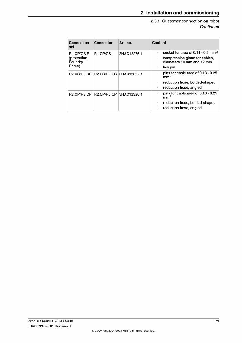
ContentArt. no.ConnectorConnectionset
• socket for area of 0.14 - 0.5 mm2
• compression gland for cables,diameters 10 mm and 12 mm
• key pin
3HAC12276-1R1.CP/CSR1.CP/CS F(protectionFoundryPrime)
• pins for cable area of 0.13 - 0.25mm2
• reduction hose, bottled-shaped• reduction hose, angled
3HAC12327-1R2.CS/R3.CSR2.CS/R3.CS
• pins for cable area of 0.13 - 0.25mm2
• reduction hose, bottled-shaped• reduction hose, angled
3HAC12326-1R2.CP/R3.CPR2.CP/R3.CP
Product manual - IRB 4400 793HAC022032-001 Revision: T
© Copyright 2004-2020 ABB. All rights reserved.
2 Installation and commissioning2.6.1 Customer connection on robot
Continued
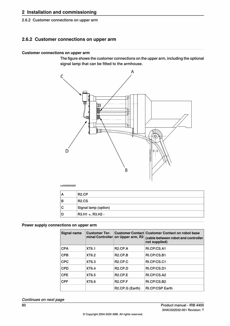
2.6.2 Customer connections on upper arm
Customer connections on upper armThe figure shows the customer connections on the upper arm, including the optionalsignal lamp that can be fitted to the armhouse.
xx0300000269
R2.CPA
R2.CSB
Signal lamp (option)C
R3.H1 +, R3.H2 -D
Power supply connections on upper arm
Customer Contact on robot base(cable between robot and controllernot supplied)
CustomerContacton Upper arm, R2
Customer Ter-minal Controller
Signal name
RI.CP/CS.A1R2.CP.AXT6.1CPA
RI.CP/CS.B1R2.CP.BXT6.2CPB
RI.CP/CS.C1R2.CP.CXT6.3CPC
RI.CP/CS.D1R2.CP.DXT6.4CPD
RI.CP/CS.A2R2.CP.EXT6.5CPE
RI.CP/CS.B2R2.CP.FXT6.6CPF
RI.CP/CSP EarthR2.CP.G (Earth)
Continues on next page80 Product manual - IRB 4400
3HAC022032-001 Revision: T© Copyright 2004-2020 ABB. All rights reserved.
2 Installation and commissioning2.6.2 Customer connections on upper arm
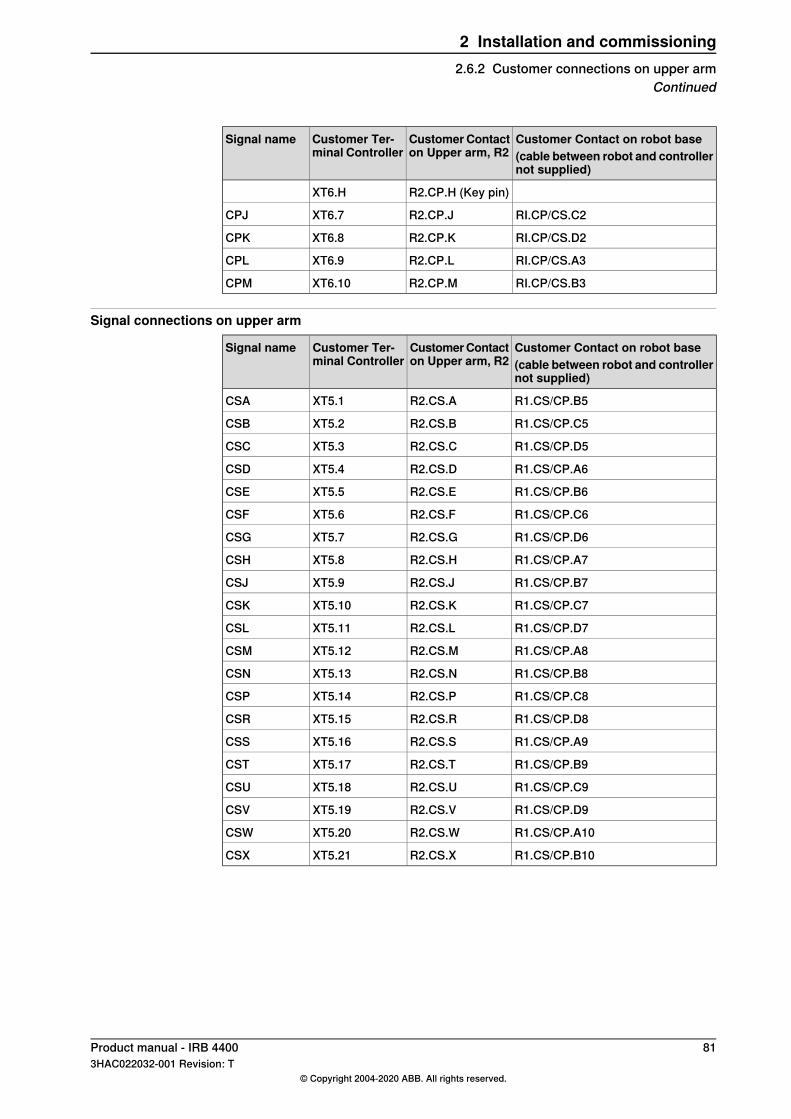
Customer Contact on robot base(cable between robot and controllernot supplied)
CustomerContacton Upper arm, R2
Customer Ter-minal Controller
Signal name
R2.CP.H (Key pin)XT6.H
RI.CP/CS.C2R2.CP.JXT6.7CPJ
RI.CP/CS.D2R2.CP.KXT6.8CPK
RI.CP/CS.A3R2.CP.LXT6.9CPL
RI.CP/CS.B3R2.CP.MXT6.10CPM
Signal connections on upper arm
Customer Contact on robot base(cable between robot and controllernot supplied)
CustomerContacton Upper arm, R2
Customer Ter-minal Controller
Signal name
R1.CS/CP.B5R2.CS.AXT5.1CSA
R1.CS/CP.C5R2.CS.BXT5.2CSB
R1.CS/CP.D5R2.CS.CXT5.3CSC
R1.CS/CP.A6R2.CS.DXT5.4CSD
R1.CS/CP.B6R2.CS.EXT5.5CSE
R1.CS/CP.C6R2.CS.FXT5.6CSF
R1.CS/CP.D6R2.CS.GXT5.7CSG
R1.CS/CP.A7R2.CS.HXT5.8CSH
R1.CS/CP.B7R2.CS.JXT5.9CSJ
R1.CS/CP.C7R2.CS.KXT5.10CSK
R1.CS/CP.D7R2.CS.LXT5.11CSL
R1.CS/CP.A8R2.CS.MXT5.12CSM
R1.CS/CP.B8R2.CS.NXT5.13CSN
R1.CS/CP.C8R2.CS.PXT5.14CSP
R1.CS/CP.D8R2.CS.RXT5.15CSR
R1.CS/CP.A9R2.CS.SXT5.16CSS
R1.CS/CP.B9R2.CS.TXT5.17CST
R1.CS/CP.C9R2.CS.UXT5.18CSU
R1.CS/CP.D9R2.CS.VXT5.19CSV
R1.CS/CP.A10R2.CS.WXT5.20CSW
R1.CS/CP.B10R2.CS.XXT5.21CSX
Product manual - IRB 4400 813HAC022032-001 Revision: T
© Copyright 2004-2020 ABB. All rights reserved.
2 Installation and commissioning2.6.2 Customer connections on upper arm
Continued
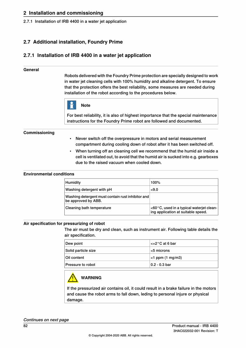
2.7 Additional installation, Foundry Prime
2.7.1 Installation of IRB 4400 in a water jet application
GeneralRobots delivered with the Foundry Prime protection are specially designed to workin water jet cleaning cells with 100% humidity and alkaline detergent. To ensurethat the protection offers the best reliability, some measures are needed duringinstallation of the robot according to the procedures below.
Note
For best reliability, it is also of highest importance that the special maintenanceinstructions for the Foundry Prime robot are followed and documented.
Commissioning• Never switch off the overpressure in motors and serial measurement
compartment during cooling down of robot after it has been switched off.• When turning off an cleaning cell we recommend that the humid air inside a
cell is ventilated out, to avoid that the humid air is sucked into e.g. gearboxesdue to the raised vacuum when cooled down.
Environmental conditions
100%Humidity
<9.0Washing detergent with pH
Washing detergent must contain rust inhibitor andbe approved by ABB.
<60°C, used in a typical waterjet clean-ing application at suitable speed.
Cleaning bath temperature
Air specification for pressurizing of robotThe air must be dry and clean, such as instrument air. Following table details theair specification.
<+2°C at 6 barDew point
<5 micronsSolid particle size
<1 ppm (1 mg/m3)Oil content
0.2 - 0.3 barPressure to robot
WARNING
If the pressurized air contains oil, it could result in a brake failure in the motorsand cause the robot arms to fall down, leding to personal injure or physicaldamage.
Continues on next page82 Product manual - IRB 4400
3HAC022032-001 Revision: T© Copyright 2004-2020 ABB. All rights reserved.
2 Installation and commissioning2.7.1 Installation of IRB 4400 in a water jet application
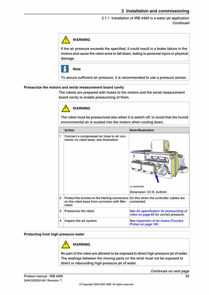
WARNING
If the air pressure exceeds the specified, it could result in a brake failure in themotors and cause the robot arms to fall down, leding to personal injure or physicaldamage.
Note
To secure sufficient air pressure, it is recommended to use a pressure sensor.
Pressurize the motors and serial measurement board cavityThe robots are prepared with hoses to the motors and the serial measurementboard cavity to enable pressurizing of them.
WARNING
The robot must be pressurized also when it is switch off, to avoid that the humidenvironmental air is sucked into the motors when cooling down.
Note/IllustrationAction
xx1500002398
Dimension: G1/8, d=6mm
Connect a compressed air hose to air con-nector on robot base, see illustration.
1
Do this when the controller cables areconnected.
Protect the screws on the Harting connectorson the robot base from corrosion with Mer-casol.
2
See Air specification for pressurizing ofrobot on page 82 for correct pressure.
Pressurize the robot.3
See Inspection of air hoses (FoundryPrime) on page 100.
Inspect the air system.4
Protecting from high pressure water
WARNING
No part of the robot are allowed to be exposed to direct high pressure jet of water.The sealings between the moving parts on the wrist must not be exposed todirect or rebounding high-pressure jet of water.
Continues on next pageProduct manual - IRB 4400 833HAC022032-001 Revision: T
© Copyright 2004-2020 ABB. All rights reserved.
2 Installation and commissioning2.7.1 Installation of IRB 4400 in a water jet application
Continued
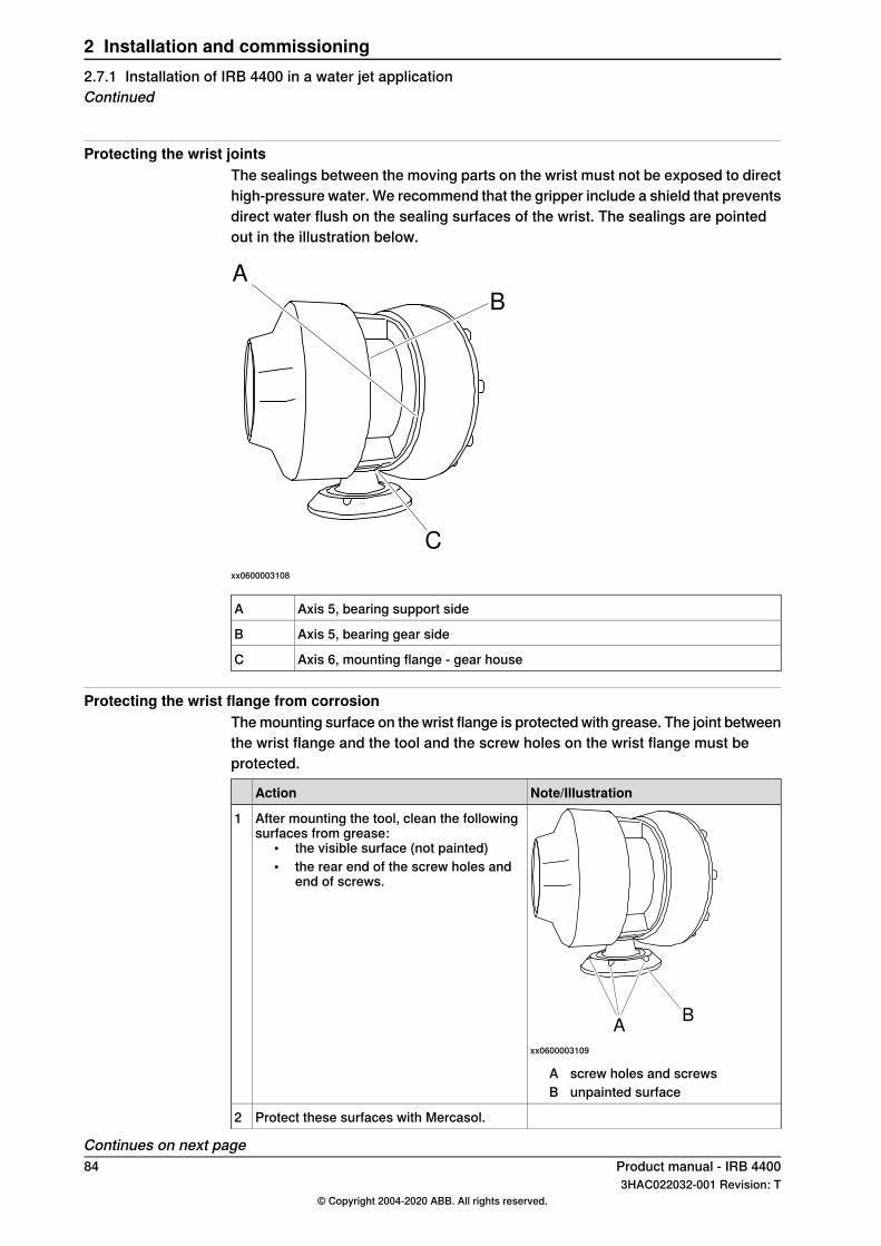
Protecting the wrist jointsThe sealings between the moving parts on the wrist must not be exposed to directhigh-pressure water. We recommend that the gripper include a shield that preventsdirect water flush on the sealing surfaces of the wrist. The sealings are pointedout in the illustration below.
A
B
C
xx0600003108
Axis 5, bearing support sideA
Axis 5, bearing gear sideB
Axis 6, mounting flange - gear houseC
Protecting the wrist flange from corrosionThe mounting surface on the wrist flange is protected with grease. The joint betweenthe wrist flange and the tool and the screw holes on the wrist flange must beprotected.
Note/IllustrationAction
AB
xx0600003109
After mounting the tool, clean the followingsurfaces from grease:
• the visible surface (not painted)• the rear end of the screw holes and
end of screws.
1
A screw holes and screwsB unpainted surface
Protect these surfaces with Mercasol.2
Continues on next page84 Product manual - IRB 4400
3HAC022032-001 Revision: T© Copyright 2004-2020 ABB. All rights reserved.
2 Installation and commissioning2.7.1 Installation of IRB 4400 in a water jet applicationContinued
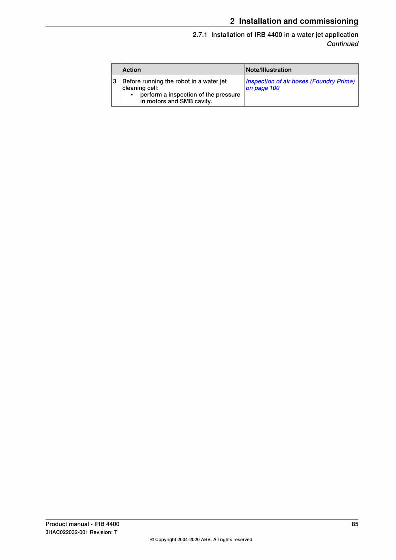
Note/IllustrationAction
Inspection of air hoses (Foundry Prime)on page 100
Before running the robot in a water jetcleaning cell:
• perform a inspection of the pressurein motors and SMB cavity.
3
Product manual - IRB 4400 853HAC022032-001 Revision: T
© Copyright 2004-2020 ABB. All rights reserved.
2 Installation and commissioning2.7.1 Installation of IRB 4400 in a water jet application
Continued
2.7.2 Commissioning (Foundry Prime)
GeneralThe following should be taken in consideration when running a robot in a water jetapplication cell:
CAUTION
Never switch off the overpressure in motors and serial measurement compartmentduring cooling down of robot after it has been switched off.
Note
To reduce the risk for corrosion due to condensation in gearboxes, it is requiredthat the robot is running with high speed on each axes at least on one occasioneach hour. This is to lubricate the gearbox cavities.
Note
When turning off a cleaning cell we recommend that the humid air is ventilatedout from the cell, to avoid that the humid air is sucked into gearboxes for example,due to the raised vacuum when cooled down.
86 Product manual - IRB 44003HAC022032-001 Revision: T
© Copyright 2004-2020 ABB. All rights reserved.
2 Installation and commissioning2.7.2 Commissioning (Foundry Prime)
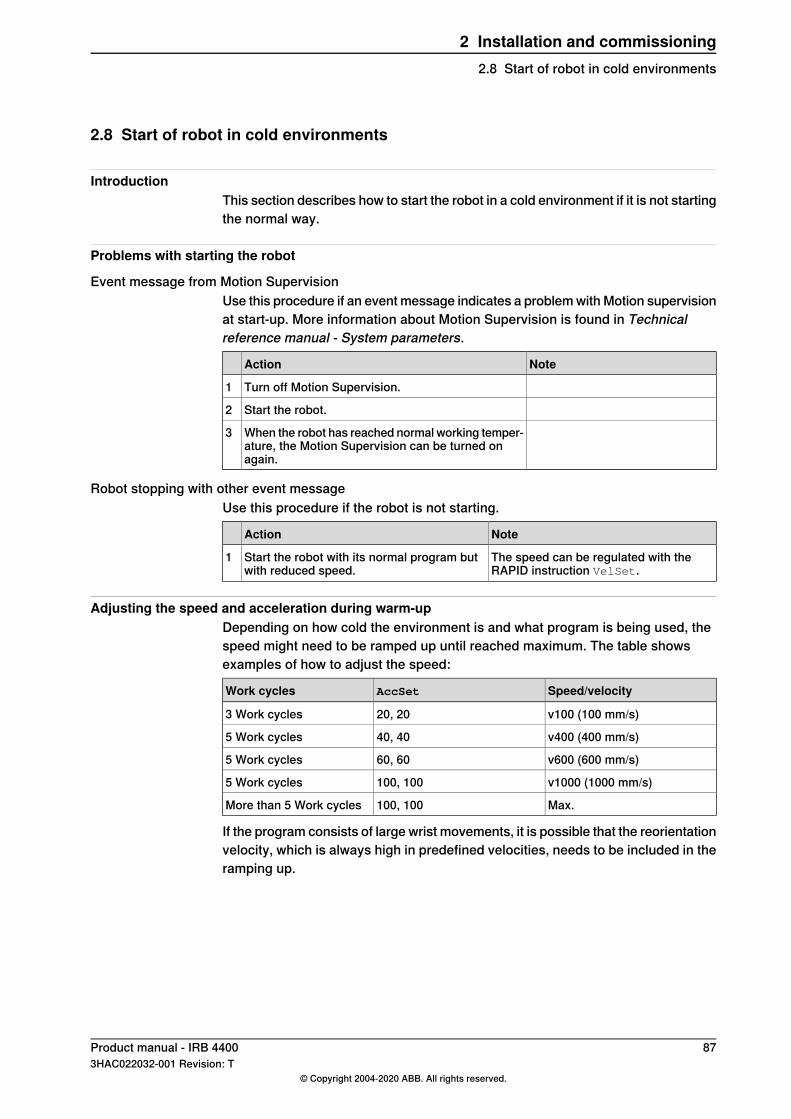
2.8 Start of robot in cold environments
IntroductionThis section describes how to start the robot in a cold environment if it is not startingthe normal way.
Problems with starting the robot
Event message from Motion SupervisionUse this procedure if an event message indicates a problem with Motion supervisionat start-up. More information about Motion Supervision is found in Technicalreference manual - System parameters.
NoteAction
Turn off Motion Supervision.1
Start the robot.2
When the robot has reached normal working temper-ature, the Motion Supervision can be turned onagain.
3
Robot stopping with other event messageUse this procedure if the robot is not starting.
NoteAction
The speed can be regulated with theRAPID instruction VelSet.
Start the robot with its normal program butwith reduced speed.
1
Adjusting the speed and acceleration during warm-upDepending on how cold the environment is and what program is being used, thespeed might need to be ramped up until reached maximum. The table showsexamples of how to adjust the speed:
Speed/velocityAccSetWork cycles
v100 (100 mm/s)20, 203 Work cycles
v400 (400 mm/s)40, 405 Work cycles
v600 (600 mm/s)60, 605 Work cycles
v1000 (1000 mm/s)100, 1005 Work cycles
Max.100, 100More than 5 Work cycles
If the program consists of large wrist movements, it is possible that the reorientationvelocity, which is always high in predefined velocities, needs to be included in theramping up.
Product manual - IRB 4400 873HAC022032-001 Revision: T
© Copyright 2004-2020 ABB. All rights reserved.
2 Installation and commissioning2.8 Start of robot in cold environments

This page is intentionally left blank
3 Maintenance3.1 Introduction
Structure of this chapterThis chapter describes all the maintenance activities recommended for the IRB4400.It is based on the maintenance schedule found at the beginning of the chapter.The schedule contains information about required maintenance activities includingintervals, and refers to procedures for the activities.Each procedure contains all the information required to perform the activity,including required tools and materials.The procedures are gathered in different sections and divided according to themaintenance activity.
Safety informationObserve all safety information before conducting any service work.There are general safety aspects that must be read through, as well as more specificsafety information that describes the danger and safety risks when performing theprocedures. Read the chapter Safety on page 17 before performing any servicework.
Note
If the IRB 4400 is connected to power, always make sure that the IRB 4400 isconnected to protective earth and a residual current device (RCD) before startingany maintenance work.For more information see:
• Product manual - IRC5• Product manual - IRC5 Panel Mounted Controller
Product manual - IRB 4400 893HAC022032-001 Revision: T
© Copyright 2004-2020 ABB. All rights reserved.
3 Maintenance3.1 Introduction
3.2 Introduction for Foundry Prime robots
IntroductionThe Foundry Prime robots are designed for installation and operation in very hardenvironments. Misuse of the robots, as well as poor installation, cleaning,maintenance, and repair can be harmful for the functioning of the robot.To eliminate these risks appropriate equipment and procedures are required wheninstalling, cleaning, maintaining, and repairing ABB Foundry Prime robots.An extended maintenance program including service activities and schedule isrequired.Cleaning and maintenance of robots with Foundry Prime protection shall beperformed by trained personnel.
Specific maintenance activities and intervals for Foundry PrimeThe Foundry Prime robots have specific maintenance activities and intervalscompared to standard robots:
• More comprehensive• More frequent• Sample activities for check of lubrication• Conditional - for example, water content in gearbox control/decide
replacement intervalsPreventive measures every 6 months secure the uptime of the robot:
• Inspection of oil level in gearboxes• Surface treatment• Cable harness• Balancing device
Activity to lubricate gearboxes cavities and gearsRun each axis on high speed at least one occasion per hour. This activity willlubricate the gearbox cavities and gears, which reduce the risk for corrosion dueto condensation in gearboxes.
Non-predictable situationsNon-predictable situations also give rise to inspections of the robot. Any damagemust be attended to immediately.
Note
Repair damages on painted surfaces as soon as possible. Use the touch-up kit3HAC035355-001 for Foundry Prime protection.
Warranty claimsWarranty claims for defect products due to misuse or failure to fulfil operationaland maintenance requirements will not be approved.
90 Product manual - IRB 44003HAC022032-001 Revision: T
© Copyright 2004-2020 ABB. All rights reserved.
3 Maintenance3.2 Introduction for Foundry Prime robots
3.3 Maintenance schedule
3.3.1 Specification of maintenance intervals
IntroductionThe intervals are specified in different ways depending on the type of maintenanceactivity to be carried out and the working conditions of the IRB 4400:
• Calendar time: specified in months regardless of whether the system isrunning or not.
• Operating time: specified in operating hours. More frequent running meansmore frequent maintenance activities.
• SIS: specified by the robot's SIS (Service Information System). A typicalvalue is given for a typical work cycle, but the value will differ depending onhow hard each part is run.The SIS used in M2004 is further described in theOperatingmanual - ServiceInformation System.
Robots with the functionality Service Information System activated can show activecounters in the device browser in RobotStudio, or on the FlexPendant.
Product manual - IRB 4400 913HAC022032-001 Revision: T
© Copyright 2004-2020 ABB. All rights reserved.
3 Maintenance3.3.1 Specification of maintenance intervals
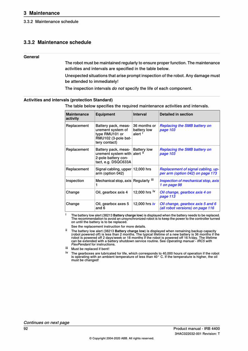
3.3.2 Maintenance schedule
GeneralThe robot must be maintained regularly to ensure proper function. The maintenanceactivities and intervals are specified in the table below.Unexpected situations that arise prompt inspection of the robot. Any damage mustbe attended to immediately!The inspection intervals do not specify the life of each component.
Activities and intervals (protection Standard)The table below specifies the required maintenance activities and intervals.
Detailed in sectionIntervalEquipmentMaintenanceactivity
Replacing the SMB battery onpage 103
36 months orbattery lowalert i
Battery pack, meas-urement system oftype RMU101 orRMU102 (3-pole bat-tery contact)
Replacement
Replacing the SMB battery onpage 103
Battery lowalert ii
Battery pack, meas-urement system with2-pole battery con-tact, e.g. DSQC633A
Replacement
Replacement of signal cabling, up-per arm (option 042) on page 173
12,000 hrsSignal cabling, upperarm (option 042)
Replacement
Inspection of mechanical stop, axis1 on page 98
Regularly iiiMechanical stop, axis1
Inspection
Oil change, gearbox axis 4 onpage 113
12,000 hrs ivOil, gearbox axis 4Change
Oil change, gearbox axis 5 and 6(all robot versions) on page 116
12,000 hrs ivOil, gearbox axes 5and 6
Change
i The battery low alert (38213Battery charge low) is displayed when the battery needs to be replaced.The recommendation to avoid an unsynchronized robot is to keep the power to the controller turnedon until the battery is to be replaced.See the replacement instruction for more details.
ii The battery low alert (38213 Battery charge low) is displayed when remaining backup capacity(robot powered off) is less than 2 months. The typical lifetime of a new battery is 36 months if therobot is powered off 2 days/week or 18 months if the robot is powered off 16 h/day. The lifetimecan be extended with a battery shutdown service routine. See Operating manual - IRC5 withFlexPendant for instructions.
iii Must be replaced if bent!iv The gearboxes are lubricated for life, which corresponds to 40,000 hours of operation if the robot
is operating with an ambient temperature of less than 40° C. If the temperature is higher, the oilmust be changed!
Continues on next page92 Product manual - IRB 4400
3HAC022032-001 Revision: T© Copyright 2004-2020 ABB. All rights reserved.
3 Maintenance3.3.2 Maintenance schedule
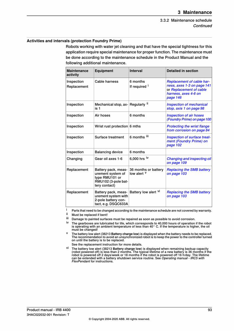
Activities and intervals (protection Foundry Prime)Robots working with water jet cleaning and that have the special tightness for thisapplication require special maintenance for proper function. The maintenance mustbe done according to the maintenance schedule in the Product Manual and thefollowing additional maintenance.
Detailed in sectionIntervalEquipmentMaintenanceactivity
Replacement of cable har-ness, axes 1-3 on page 141or Replacement of cableharness, axes 4-6 onpage 146
6 monthsIf required i
Cable harnessInspectionReplacement
Inspection of mechanicalstop, axis 1 on page 98
Regularly iiMechanical stop, ax-is 1
Inspection
Inspection of air hoses(FoundryPrime) on page100
6 monthsAir hosesInspection
Protecting the wrist flangefrom corrosion on page 84
6 mthsWrist rust protectionInspection
Inspection of surface treat-ment (Foundry Prime) onpage 102
6 months iiiSurface treatmentInspection
6 monthsBalancing deviceInspection
Changing and inspecting oilon page 109
6,000 hrs ivGear oil axes 1-6Changing
Replacing the SMB batteryon page 103
36 months or batterylow alert v
Battery pack, meas-urement system oftype RMU101 orRMU102 (3-pole bat-tery contact)
Replacement
Replacing the SMB batteryon page 103
Battery low alert viBattery pack, meas-urement system with2-pole battery con-tact, e.g. DSQC633A
Replacement
i Parts that need to be changed according to the maintenance schedule are not covered by warranty.ii Must be replaced if bent!iii Damage to painted surfaces must be repaired as soon as possible to avoid corrosion.iv The gearboxes are lubricated for life, which corresponds to 40,000 hours of operation if the robot
is operating with an ambient temperature of less than 40° C. If the temperature is higher, the oilmust be changed!
v The battery low alert (38213Battery charge low) is displayed when the battery needs to be replaced.The recommendation to avoid an unsynchronized robot is to keep the power to the controller turnedon until the battery is to be replaced.See the replacement instruction for more details.
vi The battery low alert (38213 Battery charge low) is displayed when remaining backup capacity(robot powered off) is less than 2 months. The typical lifetime of a new battery is 36 months if therobot is powered off 2 days/week or 18 months if the robot is powered off 16 h/day. The lifetimecan be extended with a battery shutdown service routine. See Operating manual - IRC5 withFlexPendant for instructions.
Product manual - IRB 4400 933HAC022032-001 Revision: T
© Copyright 2004-2020 ABB. All rights reserved.
3 Maintenance3.3.2 Maintenance schedule
Continued
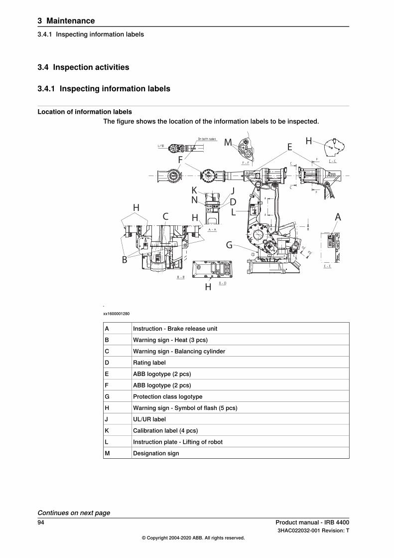
3.4 Inspection activities
3.4.1 Inspecting information labels
Location of information labelsThe figure shows the location of the information labels to be inspected.
A
B
C
D
E
F
G
H
H
H
H
JK
L
M
N
xx1600001280
Instruction - Brake release unitA
Warning sign - Heat (3 pcs)B
Warning sign - Balancing cylinderC
Rating labelD
ABB logotype (2 pcs)E
ABB logotype (2 pcs)F
Protection class logotypeG
Warning sign - Symbol of flash (5 pcs)H
UL/UR labelJ
Calibration label (4 pcs)K
Instruction plate - Lifting of robotL
Designation signM
Continues on next page94 Product manual - IRB 4400
3HAC022032-001 Revision: T© Copyright 2004-2020 ABB. All rights reserved.
3 Maintenance3.4.1 Inspecting information labels
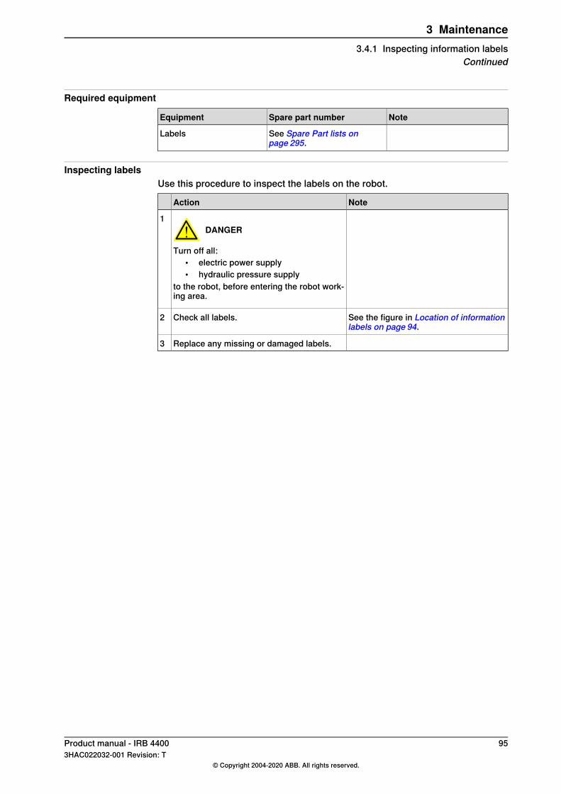
Required equipment
NoteSpare part numberEquipment
See Spare Part lists onpage 295.
Labels
Inspecting labelsUse this procedure to inspect the labels on the robot.
NoteAction
DANGER
Turn off all:• electric power supply• hydraulic pressure supply
to the robot, before entering the robot work-ing area.
1
See the figure in Location of informationlabels on page 94.
Check all labels.2
Replace any missing or damaged labels.3
Product manual - IRB 4400 953HAC022032-001 Revision: T
© Copyright 2004-2020 ABB. All rights reserved.
3 Maintenance3.4.1 Inspecting information labels
Continued
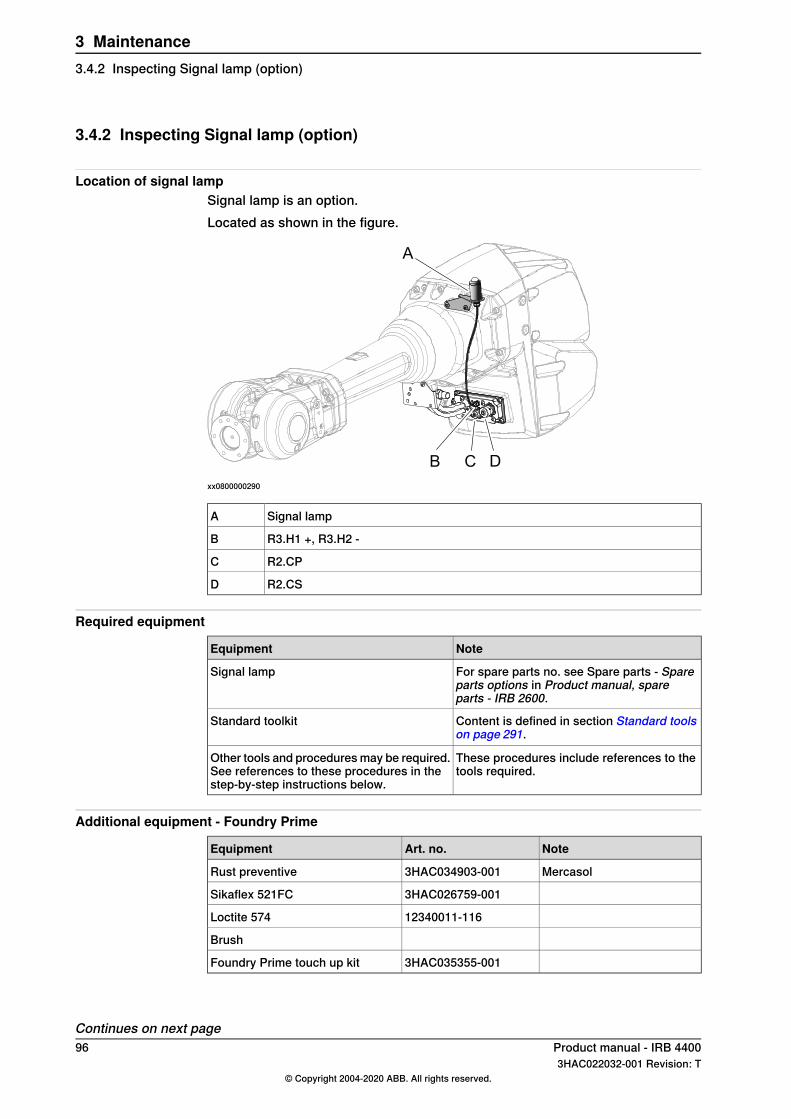
3.4.2 Inspecting Signal lamp (option)
Location of signal lampSignal lamp is an option.Located as shown in the figure.
A
B C D
xx0800000290
Signal lampA
R3.H1 +, R3.H2 -B
R2.CPC
R2.CSD
Required equipment
NoteEquipment
For spare parts no. see Spare parts - Spareparts options in Product manual, spareparts - IRB 2600.
Signal lamp
Content is defined in section Standard toolson page 291.
Standard toolkit
These procedures include references to thetools required.
Other tools and procedures may be required.See references to these procedures in thestep-by-step instructions below.
Additional equipment - Foundry Prime
NoteArt. no.Equipment
Mercasol3HAC034903-001Rust preventive
3HAC026759-001Sikaflex 521FC
12340011-116Loctite 574
Brush
3HAC035355-001Foundry Prime touch up kit
Continues on next page96 Product manual - IRB 4400
3HAC022032-001 Revision: T© Copyright 2004-2020 ABB. All rights reserved.
3 Maintenance3.4.2 Inspecting Signal lamp (option)
CAUTION
Always cut the paint with a knife and grind the paint edge when disassemblingparts. SeeCut the paint or surface on the robot before replacing parts on page137.
Inspecting signal lampUse this procedure to inspect the function of the signal lamp.
Note
If the signal lamp is damaged, it shall be replaced!
NoteAction
Check that the signal lamp is lit when motorsare put in operation ("MOTORS ON").
1
If the signal lamp is not lit, continue tracingthe fault with the steps below.
2
DANGER
Turn off all:• electric power supply• hydraulic pressure supply
to the robot, before entering the robot work-ing area.
3
Check whether the signal lamp is broken. Ifso, replace.
4
Check the cable connections.5
24VMeasure the voltage in connectors, motoraxis 3.
6
Check the cabling. If a fault is detected, re-place.
7
Seal and paint the joints that have beenopened. Also repair possible damages of thespecial Foundry Prime paint coat of the robot.See Cut the paint or surface on the robot be-fore replacing parts on page 137.
8
Product manual - IRB 4400 973HAC022032-001 Revision: T
© Copyright 2004-2020 ABB. All rights reserved.
3 Maintenance3.4.2 Inspecting Signal lamp (option)
Continued
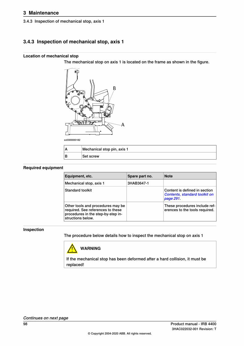
3.4.3 Inspection of mechanical stop, axis 1
Location of mechanical stopThe mechanical stop on axis 1 is located on the frame as shown in the figure.
xx0300000182
Mechanical stop pin, axis 1A
Set screwB
Required equipment
NoteSpare part no.Equipment, etc.
3HAB3647-1Mechanical stop, axis 1
Content is defined in sectionContents, standard toolkit onpage 291.
Standard toolkit
These procedures include ref-erences to the tools required.
Other tools and procedures may berequired. See references to theseprocedures in the step-by-step in-structions below.
InspectionThe procedure below details how to inspect the mechanical stop on axis 1
WARNING
If the mechanical stop has been deformed after a hard collision, it must bereplaced!
Continues on next page98 Product manual - IRB 4400
3HAC022032-001 Revision: T© Copyright 2004-2020 ABB. All rights reserved.
3 Maintenance3.4.3 Inspection of mechanical stop, axis 1
InformationAction
DANGER
Turn off all:• electric power supply• hydraulic pressure supply• air pressure supply (do not turn off for Foundry
Prime robots!)to the robot, before entering the robot working area.
1
Check regularly that the stop pin is not bent or dam-aged in any other way.
2
Removal/refitting of themechanical stop is detailed insection Fitting, mechanicalstop axis 1 on page 68.
Note
If the mechanical stop pin has been deformed ordamaged, it must be replaced by a new one!
3
Also check that the stop pin is properly attached.4
Product manual - IRB 4400 993HAC022032-001 Revision: T
© Copyright 2004-2020 ABB. All rights reserved.
3 Maintenance3.4.3 Inspection of mechanical stop, axis 1
Continued
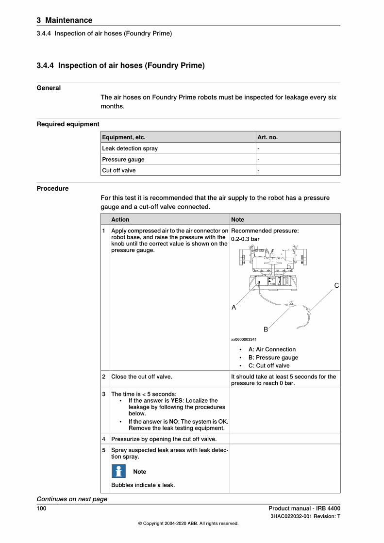
3.4.4 Inspection of air hoses (Foundry Prime)
GeneralThe air hoses on Foundry Prime robots must be inspected for leakage every sixmonths.
Required equipment
Art. no.Equipment, etc.
-Leak detection spray
-Pressure gauge
-Cut off valve
ProcedureFor this test it is recommended that the air supply to the robot has a pressuregauge and a cut-off valve connected.
NoteAction
Recommended pressure:Apply compressed air to the air connector onrobot base, and raise the pressure with theknob until the correct value is shown on thepressure gauge.
10.2-0.3 bar
A
B
C
xx0600003341
• A: Air Connection• B: Pressure gauge• C: Cut off valve
It should take at least 5 seconds for thepressure to reach 0 bar.
Close the cut off valve.2
The time is < 5 seconds:• If the answer is YES: Localize the
leakage by following the proceduresbelow.
• If the answer isNO: The system is OK.Remove the leak testing equipment.
3
Pressurize by opening the cut off valve.4
Spray suspected leak areas with leak detec-tion spray.
Note
Bubbles indicate a leak.
5
Continues on next page100 Product manual - IRB 4400
3HAC022032-001 Revision: T© Copyright 2004-2020 ABB. All rights reserved.
3 Maintenance3.4.4 Inspection of air hoses (Foundry Prime)
NoteAction
When the leak is localized: correct the leak.6
Product manual - IRB 4400 1013HAC022032-001 Revision: T
© Copyright 2004-2020 ABB. All rights reserved.
3 Maintenance3.4.4 Inspection of air hoses (Foundry Prime)
Continued
3.4.5 Inspection of surface treatment (Foundry Prime)
Introduction to inspection of surface treatmentDamage to painted surfaces must be repaired as soon as possible to avoidcorrosion. All painted surfaces on the robot must be inspected.
Required equipment
NoteEquipment, etc.
See Touch up paint for Foundry Prime robots inpartlistSpare Part lists on page 295.
Touch up paint Foundry Prime 2, grey
Additional equipment - Foundry Prime
NoteArticle numberEquipment
Mercasol. Recommendeddrying time is 24h.
3HAC034903-001Rust preventive
3HAC026759-001Sikaflex 521FC
12340011-116Loctite 574
Brush
3HAC035355-001Foundry Prime touch up kit
Inspection and repair of surface treatmentUse this procedure to inspect the surface treatment on Foundry Prime robots.
InformationAction
Inspect all painted surfaces for damage.1
Repair any damage as described in the in-struction included in the spare part kit.
2
102 Product manual - IRB 44003HAC022032-001 Revision: T
© Copyright 2004-2020 ABB. All rights reserved.
3 Maintenance3.4.5 Inspection of surface treatment (Foundry Prime)
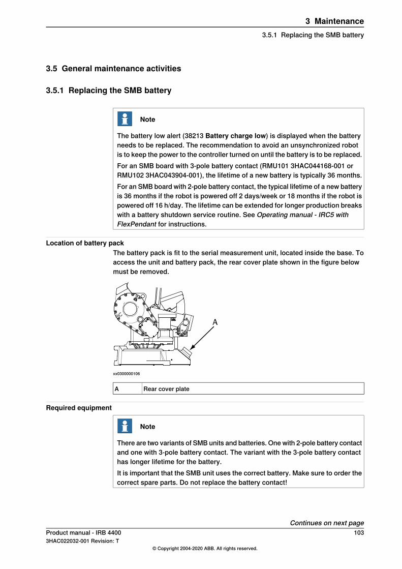
3.5 General maintenance activities
3.5.1 Replacing the SMB battery
Note
The battery low alert (38213 Battery charge low) is displayed when the batteryneeds to be replaced. The recommendation to avoid an unsynchronized robotis to keep the power to the controller turned on until the battery is to be replaced.For an SMB board with 3-pole battery contact (RMU101 3HAC044168-001 orRMU102 3HAC043904-001), the lifetime of a new battery is typically 36 months.For an SMB board with 2-pole battery contact, the typical lifetime of a new batteryis 36 months if the robot is powered off 2 days/week or 18 months if the robot ispowered off 16 h/day. The lifetime can be extended for longer production breakswith a battery shutdown service routine. See Operating manual - IRC5 withFlexPendant for instructions.
Location of battery packThe battery pack is fit to the serial measurement unit, located inside the base. Toaccess the unit and battery pack, the rear cover plate shown in the figure belowmust be removed.
xx0300000106
Rear cover plateA
Required equipment
Note
There are two variants of SMB units and batteries. One with 2-pole battery contactand one with 3-pole battery contact. The variant with the 3-pole battery contacthas longer lifetime for the battery.It is important that the SMB unit uses the correct battery. Make sure to order thecorrect spare parts. Do not replace the battery contact!
Continues on next pageProduct manual - IRB 4400 1033HAC022032-001 Revision: T
© Copyright 2004-2020 ABB. All rights reserved.
3 Maintenance3.5.1 Replacing the SMB battery
NoteEquipment, etc.
For spare part number, see Spare Parts - Serialmeasurement unit.
Battery pack
The contents are defined in section Contents,standard toolkit on page 291.
Standard toolkit
These procedures include references to thetools required.
Other tools and procedures may be re-quired. See references to these proced-ures in the step-by-step instructions be-low.
Replacement, battery packThe procedure below details how to replace the battery pack in the serialmeasurement unit.
Info/IllustrationActionStep
xx0200000023
1
WARNING
The unit is sensitive to ESD. Before handling the unitplease read the safety information in the section Theunit is sensitive to ESD on page 52
Set the robot to the MOTORS OFF operating mode.2This way the robot does not need to be calibratedafter the battery change.
Shown in the figure Locationof battery pack on page 103.
Remove the rear cover plate from the base.
CAUTION
Clean cover from metal residues before opening.Metal residues can cause shortage on the boardswhich can result in hazardous failures.
3
Loosen the battery terminals from the serial measur-ing board and cut the clasps that keep the batterypack in place.
4
Remove the old battery pack.5
Fit a new battery pack with two clasps and connectthe terminals to the serial measuring board.
6
104 Product manual - IRB 44003HAC022032-001 Revision: T
© Copyright 2004-2020 ABB. All rights reserved.
3 Maintenance3.5.1 Replacing the SMB batteryContinued
3.5.2 Cleaning the IRB 4400
DANGER
Turn off all:• electric power supply• hydraulic pressure supply
to the robot, before entering the safeguarded space.
GeneralTo secure high uptime it is important that the IRB 4400 is cleaned regularly. Thefrequency of cleaning depends on the environment in which the product works.Different cleaning methods are allowed depending on the type of protection of theIRB 4400.
Note
Always verify the protection type of the robot before cleaning.
Oil spills
Oil spills from gearboxesUse the following procedure if any oil spills are detected that can be suspected tooriginate from a gearbox.
1 Inspect that the oil level in the suspected gearbox is according to therecommendations, see Inspection activities on page 94.
2 Write down the oil level.3 Inspect the oil level again after, for example, 6 months.4 If the oil level is decreased then replace the gearbox.
Oil spills discolors painted surfacesOil spills on painted surfaces of the robot can result in discoloration.
Note
After all repair and maintenance work involving oil, always wipe the robot cleanfrom all surplus oil.
Special cleaning considerationsThis section specifies some special considerations when cleaning the robot.
• Always use cleaning equipment as specified. Any other cleaning equipmentmay shorten the life of the robot.
• Always check that all protective covers are fitted to the robot before cleaning.• Never point the water jet at connectors, joints, sealings, or gaskets.• Do not use compressed air to clean the robot.
Continues on next pageProduct manual - IRB 4400 1053HAC022032-001 Revision: T
© Copyright 2004-2020 ABB. All rights reserved.
3 Maintenance3.5.2 Cleaning the IRB 4400
• Never use solvents that are not approved by ABB to clean the robot.• Do not spray from a distance closer than 0.4 m.• Do not remove any covers or other protective devices before cleaning the
robot.
Cleaning methodsThe following table defines what cleaning methods are allowed depending on theprotection type.
Cleaning methodProtectiontype
High pressure water orsteam
Rinse with waterWipewith clothVacuumcleaner
NoYes. It is highly re-commended thatthe water containsa rust-preventionsolution and thatthe manipulator isdried afterwards.
Yes. With lightcleaning deter-gent.
YesStandard
Yes i .Yes. It is highly re-commended thatthe water containsa rust-preventionsolution.
Yes. Withcleaning deter-gent approvedby ABB, spiritor isopropyl al-cohol.
YesFoundryPrime It is highly recommended
that the water and steamcontains rust preventive.If cleaning detergents areused they must be ap-proved by ABB forFoundry Prime robots.
See Approvedcleaners anddetergents onpage 107.
See Approved cleanersand detergents onpage 107.
i Perform according to section Cleaning with water and steam on page 106.
Cleaning with water and steam
Instructions for rinsing with waterABB robots with protection types Standard, Foundry Plus,Wash, or Foundry Primecan be cleaned by rinsing with water (water cleaner).1
The following list defines the prerequisites:• Maximum water pressure at the nozzle: 700 kN/m2 (7 bar) I
• Fan jet nozzle should be used, min. 45° spread• Minimum distance from nozzle to encapsulation: 0.4 meters• Maximum flow: 20 liters/min I
I Typical tap water pressure and flow
Instructions for steam or high pressure water cleaningABB robots with protection types Foundry Plus, Wash, or Foundry Prime can becleaned using a steam cleaner or high pressure water cleaner.2
The following list defines the prerequisites:• Maximum water pressure at the nozzle: 2500 kN/m2 (25 bar)
1 See Cleaning methods on page 106 for exceptions.2 See Cleaning methods on page 106 for exceptions.
Continues on next page106 Product manual - IRB 4400
3HAC022032-001 Revision: T© Copyright 2004-2020 ABB. All rights reserved.
3 Maintenance3.5.2 Cleaning the IRB 4400Continued
• Fan jet nozzle should be used, min. 45° spread• Minimum distance from nozzle to encapsulation: 0.4 meters• Maximum water temperature: 80° C
Additional cleaning instructions for Foundry Prime robots
Washing detergents• Only washing detergents approved by ABB shall be used.• The washing detergent must be cleansed continuously.• The washing detergent must contain rust inhibitor.• The detergent pH value and concentration must be checked regularly.• Allowed pH of the washing detergent is 9.0, if not stated otherwise.• The user must follow the recommendations regarding detergent concentration
and pH value.• No other additive than water is guaranteed without prior testing or agreement
with ABB. Other additives than water may have a harmful effect on the lifeof the robot and its components.
• Recommendations given by the detergent manufacturer for the specificdetergent in question must be followed.
Note
If the pH value or the detergent concentration is varying from its originalspecification, it can become very corrosive.
Approved cleaners and detergentsAll cleaners and detergents must be approved by ABB before use. Contact ABBRobotics Sales Support to get the latest released list of approved cleaners anddetergents.
Temperature of cleaning bath• Maximum temperature <60ºC.
Ambient temperature must not be higher than +45° C.
Note
Make sure that the special Foundry Prime painting of the robot is not brokenduring testing, installation, or repair work. Use the touch up kit available forFoundry Prime (article number 3HAC035355-001) to repair any damages in thepaint.
Washing without detergentIf the washing is performed without detergent, the water must contain rust inhibitor.
CablesMovable cables need to be able to move freely:
• Remove waste material, such as sand, dust and chips, if it prevents cablemovement.
Continues on next pageProduct manual - IRB 4400 1073HAC022032-001 Revision: T
© Copyright 2004-2020 ABB. All rights reserved.
3 Maintenance3.5.2 Cleaning the IRB 4400
Continued
• Clean the cables if they have a crusty surface, for example from dry releaseagents.
108 Product manual - IRB 44003HAC022032-001 Revision: T
© Copyright 2004-2020 ABB. All rights reserved.
3 Maintenance3.5.2 Cleaning the IRB 4400Continued
3.6 Changing and inspecting oil
3.6.1 Type of lubrication in gearboxes
IntroductionThis section describes where to find information about the type of lubrication,article number and the amount of lubrication in the specific gearbox. It alsodescribes the equipment needed when working with lubrication.
Type and amount of oil in gearboxesInformation about the type of lubrication, article number as well as the amount inthe specific gearbox can be found in Technical reference manual - Lubrication ingearboxes available for registered users on myABB Business Portal, www.mypo-rtal.abb.com.
Location of gearboxesThe figure shows the location of the gearboxes.
Equipment
NoteEquipment
Includes pump with outlet pipe.Oil dispenserUse the suggested dispenser or a similar one:
• Orion OriCan article number 22590(pneumatic)
Nipple for quick connect fitting, with o-ring
Product manual - IRB 4400 1093HAC022032-001 Revision: T
© Copyright 2004-2020 ABB. All rights reserved.
3 Maintenance3.6.1 Type of lubrication in gearboxes
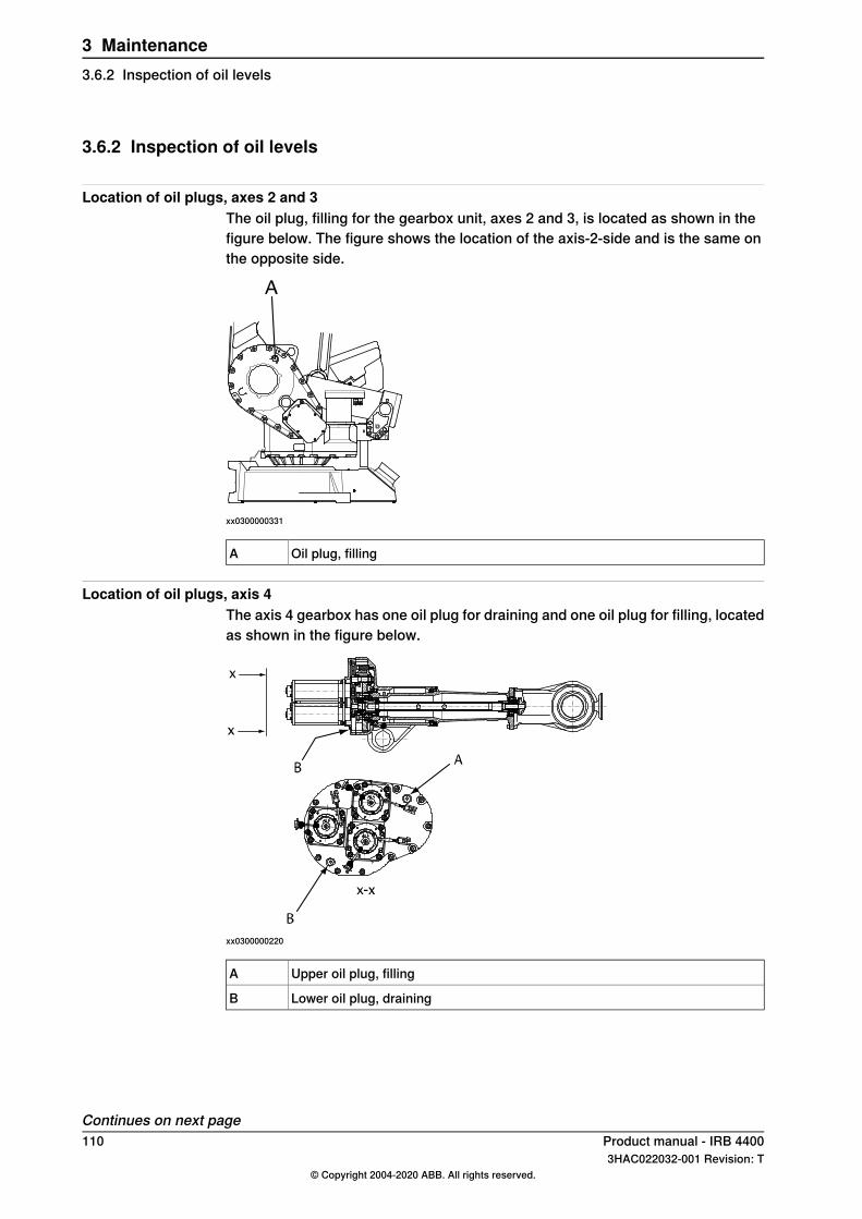
3.6.2 Inspection of oil levels
Location of oil plugs, axes 2 and 3The oil plug, filling for the gearbox unit, axes 2 and 3, is located as shown in thefigure below. The figure shows the location of the axis-2-side and is the same onthe opposite side.
xx0300000331
Oil plug, fillingA
Location of oil plugs, axis 4The axis 4 gearbox has one oil plug for draining and one oil plug for filling, locatedas shown in the figure below.
xx0300000220
Upper oil plug, fillingA
Lower oil plug, drainingB
Continues on next page110 Product manual - IRB 4400
3HAC022032-001 Revision: T© Copyright 2004-2020 ABB. All rights reserved.
3 Maintenance3.6.2 Inspection of oil levels
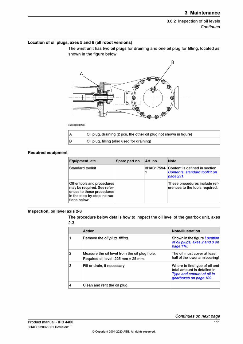
Location of oil plugs, axes 5 and 6 (all robot versions)The wrist unit has two oil plugs for draining and one oil plug for filling, located asshown in the figure below.
xx0300000223
Oil plug, draining (2 pcs, the other oil plug not shown in figure)A
Oil plug, filling (also used for draining)B
Required equipment
NoteArt. no.Spare part no.Equipment, etc.
Content is defined in sectionContents, standard toolkit onpage 291.
3HAC17594-1
Standard toolkit
These procedures include ref-erences to the tools required.
Other tools and proceduresmay be required. See refer-ences to these proceduresin the step-by-step instruc-tions below.
Inspection, oil level axis 2-3The procedure below details how to inspect the oil level of the gearbox unit, axes2-3.
Note/IllustrationAction
Shown in the figure Locationof oil plugs, axes 2 and 3 onpage 110.
Remove the oil plug, filling.1
The oil must cover at leasthalf of the lower arm bearing!
Measure the oil level from the oil plug hole.Required oil level: 225 mm ± 25 mm.
2
Where to find type of oil andtotal amount is detailed inType and amount of oil ingearboxes on page 109.
Fill or drain, if necessary.3
Clean and refit the oil plug.4
Continues on next pageProduct manual - IRB 4400 1113HAC022032-001 Revision: T
© Copyright 2004-2020 ABB. All rights reserved.
3 Maintenance3.6.2 Inspection of oil levels
Continued
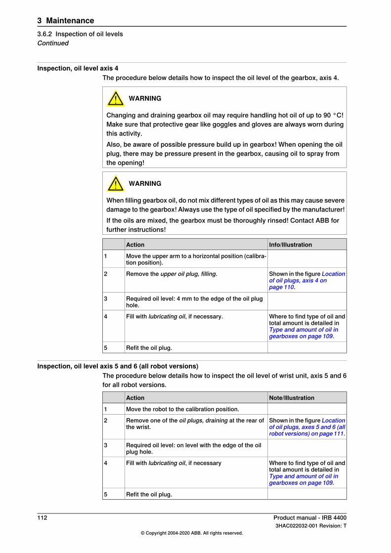
Inspection, oil level axis 4The procedure below details how to inspect the oil level of the gearbox, axis 4.
WARNING
Changing and draining gearbox oil may require handling hot oil of up to 90 °C!Make sure that protective gear like goggles and gloves are always worn duringthis activity.Also, be aware of possible pressure build up in gearbox! When opening the oilplug, there may be pressure present in the gearbox, causing oil to spray fromthe opening!
WARNING
When filling gearbox oil, do not mix different types of oil as this may cause severedamage to the gearbox! Always use the type of oil specified by the manufacturer!If the oils are mixed, the gearbox must be thoroughly rinsed! Contact ABB forfurther instructions!
Info/IllustrationAction
Move the upper arm to a horizontal position (calibra-tion position).
1
Shown in the figure Locationof oil plugs, axis 4 onpage 110.
Remove the upper oil plug, filling.2
Required oil level: 4 mm to the edge of the oil plughole.
3
Where to find type of oil andtotal amount is detailed inType and amount of oil ingearboxes on page 109.
Fill with lubricating oil, if necessary.4
Refit the oil plug.5
Inspection, oil level axis 5 and 6 (all robot versions)The procedure below details how to inspect the oil level of wrist unit, axis 5 and 6for all robot versions.
Note/IllustrationAction
Move the robot to the calibration position.1
Shown in the figure Locationof oil plugs, axes 5 and 6 (allrobot versions) on page111.
Remove one of the oil plugs, draining at the rear ofthe wrist.
2
Required oil level: on level with the edge of the oilplug hole.
3
Where to find type of oil andtotal amount is detailed inType and amount of oil ingearboxes on page 109.
Fill with lubricating oil, if necessary4
Refit the oil plug.5
112 Product manual - IRB 44003HAC022032-001 Revision: T
© Copyright 2004-2020 ABB. All rights reserved.
3 Maintenance3.6.2 Inspection of oil levelsContinued
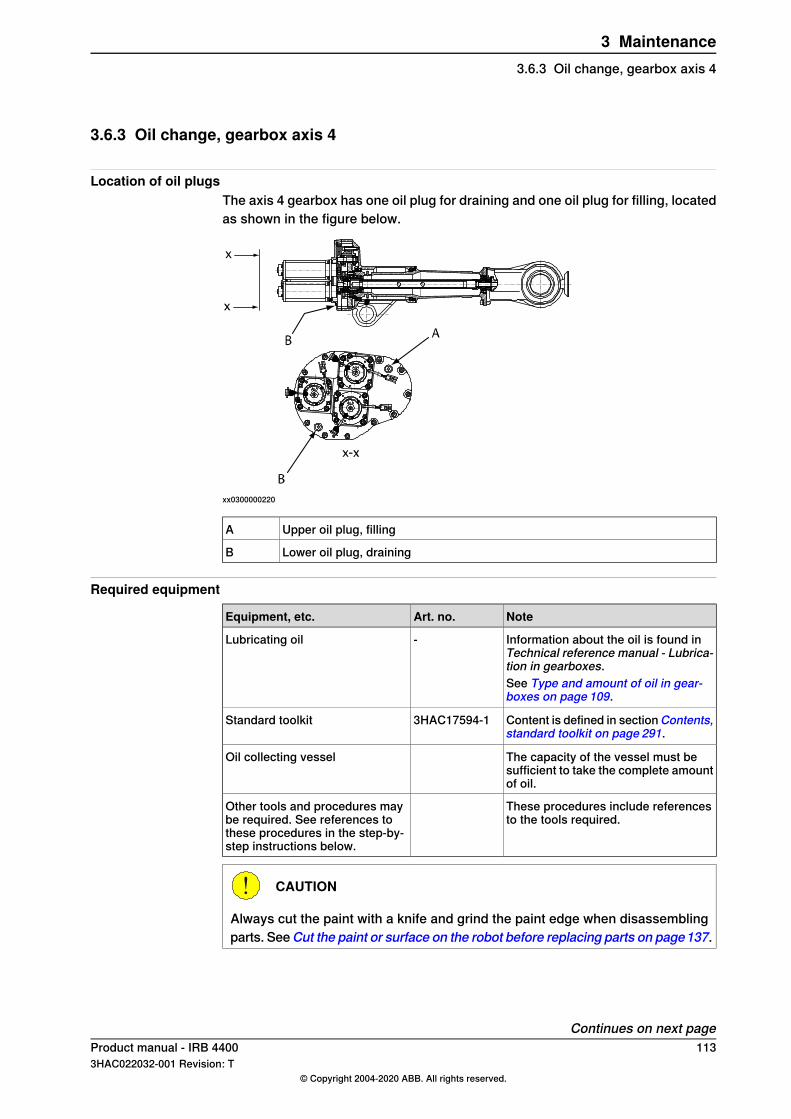
3.6.3 Oil change, gearbox axis 4
Location of oil plugsThe axis 4 gearbox has one oil plug for draining and one oil plug for filling, locatedas shown in the figure below.
xx0300000220
Upper oil plug, fillingA
Lower oil plug, drainingB
Required equipment
NoteArt. no.Equipment, etc.
Information about the oil is found inTechnical reference manual - Lubrica-tion in gearboxes.
-Lubricating oil
See Type and amount of oil in gear-boxes on page 109.
Content is defined in sectionContents,standard toolkit on page 291.
3HAC17594-1Standard toolkit
The capacity of the vessel must besufficient to take the complete amountof oil.
Oil collecting vessel
These procedures include referencesto the tools required.
Other tools and procedures maybe required. See references tothese procedures in the step-by-step instructions below.
CAUTION
Always cut the paint with a knife and grind the paint edge when disassemblingparts. SeeCut the paint or surface on the robot before replacing parts on page137.
Continues on next pageProduct manual - IRB 4400 1133HAC022032-001 Revision: T
© Copyright 2004-2020 ABB. All rights reserved.
3 Maintenance3.6.3 Oil change, gearbox axis 4
DrainingThe procedure below details how to drain the oil from the gearbox, axis 4.
Tip
When changing gearbox oil, first run the robot for a time to heat up the oil. Warmoil drains quicker than cold oil.
WARNING
Changing and draining gearbox oil may require handling hot oil of up to 90 °C!Make sure that protective gear like goggles and gloves are always worn duringthis activity.Also, be aware of possible pressure build up in gearbox! When opening the oilplug, there may be pressure present in the gearbox, causing oil to spray fromthe opening!
Info/IllustrationAction
Move the arms backward and the upper arm to anearly vertical position.
1
Shown in the figure Locationof oil plugs on page 113.
Remove the lower oil plug, draining and drain the oilinto an oil collecting vessel.
2
Capacity of the oil collectingvessel is specified in Re-quired equipment onpage 113.
Clean and refit the oil plug.3
FillingThe procedure below details how to refill the oil to the gearbox, axis 4.
Note
The specified amount of oil is based on the total volume of the gearbox. Whenchanging the oil, the amount of refilled oil may differ from the specified amount,depending on how much oil has previously been drained from the gearbox.
WARNING
When filling gearbox oil, do not mix different types of oil as this may cause severedamage to the gearbox! Always use the type of oil specified by the manufacturer!If the oils are mixed, the gearbox must be thoroughly rinsed! Contact ABB forfurther instructions!
Continues on next page114 Product manual - IRB 4400
3HAC022032-001 Revision: T© Copyright 2004-2020 ABB. All rights reserved.
3 Maintenance3.6.3 Oil change, gearbox axis 4Continued
WARNING
When filling gearbox oil, do not overfill, since this could lead to internalover-pressure inside the gearbox which in turn may:
• - damage seals and gaskets• - completely press out seals and gaskets• - prevent the manipulator from moving freely
Note/IllustrationAction
Move the upper arm to a vertical position (rear endupwards).
1
Shown in the figure Locationof oil plugs on page 113.
Remove the upper oil plug, filling.2
Where to find type of oil andtotal amount is detailed inType and amount of oil ingearboxes on page 109.
Fill the gearbox with lubricating oil.3
Correct oil level is specifiedin section Inspection of oillevels on page 110.
Clean and refit the oil plug.4
Product manual - IRB 4400 1153HAC022032-001 Revision: T
© Copyright 2004-2020 ABB. All rights reserved.
3 Maintenance3.6.3 Oil change, gearbox axis 4
Continued
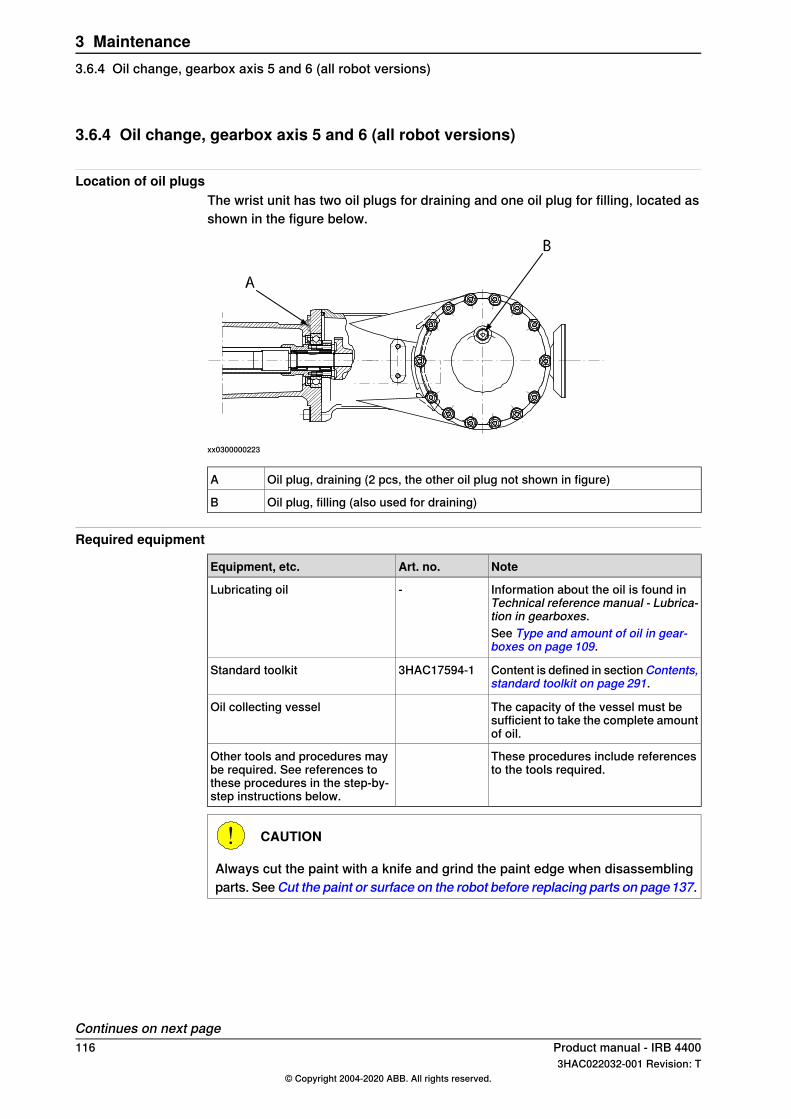
3.6.4 Oil change, gearbox axis 5 and 6 (all robot versions)
Location of oil plugsThe wrist unit has two oil plugs for draining and one oil plug for filling, located asshown in the figure below.
xx0300000223
Oil plug, draining (2 pcs, the other oil plug not shown in figure)A
Oil plug, filling (also used for draining)B
Required equipment
NoteArt. no.Equipment, etc.
Information about the oil is found inTechnical reference manual - Lubrica-tion in gearboxes.
-Lubricating oil
See Type and amount of oil in gear-boxes on page 109.
Content is defined in sectionContents,standard toolkit on page 291.
3HAC17594-1Standard toolkit
The capacity of the vessel must besufficient to take the complete amountof oil.
Oil collecting vessel
These procedures include referencesto the tools required.
Other tools and procedures maybe required. See references tothese procedures in the step-by-step instructions below.
CAUTION
Always cut the paint with a knife and grind the paint edge when disassemblingparts. SeeCut the paint or surface on the robot before replacing parts on page137.
Continues on next page116 Product manual - IRB 4400
3HAC022032-001 Revision: T© Copyright 2004-2020 ABB. All rights reserved.
3 Maintenance3.6.4 Oil change, gearbox axis 5 and 6 (all robot versions)
Draining oilThe procedure below details how to drain the oil from the wrist unit (axis 5 and 6).
Tip
When changing gearbox oil, first run the robot for a time to heat up the oil. Warmoil drains quicker than cold oil.
WARNING
Changing and draining gearbox oil may require handling hot oil of up to 90 °C!Make sure that protective gear like goggles and gloves are always worn duringthis activity.Also, be aware of possible pressure build up in gearbox! When opening the oilplug, there may be pressure present in the gearbox, causing oil to spray fromthe opening!
Info/IllustrationAction
Move the upper arm to a horizontal position and turnaxis 4 to the calibration position.
1
Turn axis 4, 135°.2
Shown in the figure Locationof oil plugs on page 116.
Remove the lower oil plug, draining at the rear of thewrist.
3
Capacity of oil collectingvessel is specified in Re-quired equipment onpage 116.
Remove the other oil plug, draining.4
Move axis 3 up -15° and let the oil run out for acouple of minutes.
5
Shown in the figure Locationof oil plugs on page 116.
Turn axis 4 so that the oil plug, filling is facingdownwards.
6
Remove the oil plug, axis 5 to drain the oil.7
Move axis 3 down to 0°.8
Move axis 4 backwards and forwards a couple oftimes to drain all the oil.
9
Clean and refit the both oil plugs, draining.10
Filling oilThe procedure below details how to fill oil to the wrist unit (axis 5 and 6).
Note
The specified amount of oil is based on the total volume of the gearbox. Whenchanging the oil, the amount of refilled oil may differ from the specified amount,depending on how much oil has previously been drained from the gearbox.
Continues on next pageProduct manual - IRB 4400 1173HAC022032-001 Revision: T
© Copyright 2004-2020 ABB. All rights reserved.
3 Maintenance3.6.4 Oil change, gearbox axis 5 and 6 (all robot versions)
Continued
WARNING
When filling gearbox oil, do not mix different types of oil as this may cause severedamage to the gearbox! Always use the type of oil specified by the manufacturer!If the oils are mixed, the gearbox must be thoroughly rinsed! Contact ABB forfurther instructions!
WARNING
When filling gearbox oil, do not overfill, since this could lead to internalover-pressure inside the gearbox which in turn may:
• - damage seals and gaskets• - completely press out seals and gaskets• - prevent the manipulator from moving freely
Note/IllustrationAction
Move the upper arm to a horizontal position and turnaxis 4 to calibration position.
1
Shown in the figure Locationof oil plugs on page 116.
Turn axis 4 so that the oil plug, filling is facing up-wards.
2
Where to find type of oil andtotal amount is detailed inType and amount of oil ingearboxes on page 109.
Fill the wrist with lubricating oil through the oil plughole, filling.Fill in intervals so that the oil runs into the wrist.
3
Correct oil level is specifiedin section Inspection of oillevels on page 110.
Clean and refit the oil plug, filling.4
118 Product manual - IRB 44003HAC022032-001 Revision: T
© Copyright 2004-2020 ABB. All rights reserved.
3 Maintenance3.6.4 Oil change, gearbox axis 5 and 6 (all robot versions)Continued
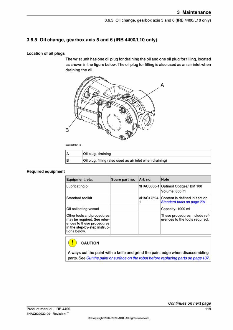
3.6.5 Oil change, gearbox axis 5 and 6 (IRB 4400/L10 only)
Location of oil plugsThe wrist unit has one oil plug for draining the oil and one oil plug for filling, locatedas shown in the figure below. The oil plug for filling is also used as an air inlet whendraining the oil.
xx0300000118
Oil plug, drainingA
Oil plug, filling (also used as air inlet when draining)B
Required equipment
NoteArt. no.Spare part no.Equipment, etc.
Optimol Optigear BM 1003HAC0860-1Lubricating oilVolume: 800 ml
Content is defined in sectionStandard tools on page 291.
3HAC17594-1
Standard toolkit
Capacity: 1000 mlOil collecting vessel
These procedures include ref-erences to the tools required.
Other tools and proceduresmay be required. See refer-ences to these proceduresin the step-by-step instruc-tions below.
CAUTION
Always cut the paint with a knife and grind the paint edge when disassemblingparts. SeeCut the paint or surface on the robot before replacing parts on page137.
Continues on next pageProduct manual - IRB 4400 1193HAC022032-001 Revision: T
© Copyright 2004-2020 ABB. All rights reserved.
3 Maintenance3.6.5 Oil change, gearbox axis 5 and 6 (IRB 4400/L10 only)
Draining oilThe procedure below details how to drain the oil from the wrist unit (axis 5 and 6),robot version IRB 4400/L10.
Tip
When changing gearbox oil, first run the robot for a time to heat up the oil. Warmoil drains quicker than cold oil.
WARNING
Changing and draining gearbox oil may require handling hot oil of up to 90 °C!Make sure that protective gear like goggles and gloves are always worn duringthis activity.Also, be aware of possible pressure build up in gearbox! When opening the oilplug, there may be pressure present in the gearbox, causing oil to spray fromthe opening!
Info/IllustrationActionStep
Move the upper arm to a horizontal position and turnaxis 4 to the calibration position.
1
Shown in the figure Locationof oil plugs on page 119.
Remove the oil plug, draining in the wrist.2
Shown in the figure Locationof oil plugs on page 119.
Turn axis 4 to a position where the oil plug, drainingis faced downwards and drain the oil into an oil col-lecting vessel.Also remove the oil plug, filling, in order to use it asan air inlet.
3
Capacity of vessel is spe-cified inRequired equipmenton page 119.
Turn axis 4 another 90° to allow the remaining oil tobe drained.
4
Clean and refit the oil plug, draining.5
Filling oilThe procedure below details how to fill oil to the wrist unit (axis 5 and 6), robotversion IRB 4400/L10.
Note
The specified amount of oil is based on the total volume of the gearbox. Whenchanging the oil, the amount of refilled oil may differ from the specified amount,depending on how much oil has previously been drained from the gearbox.
Continues on next page120 Product manual - IRB 4400
3HAC022032-001 Revision: T© Copyright 2004-2020 ABB. All rights reserved.
3 Maintenance3.6.5 Oil change, gearbox axis 5 and 6 (IRB 4400/L10 only)Continued
WARNING
When filling gearbox oil, do not mix different types of oil as this may cause severedamage to the gearbox! Always use the type of oil specified by the manufacturer!If the oils are mixed, the gearbox must be thoroughly rinsed! Contact ABB forfurther instructions!
WARNING
When filling gearbox oil, do not overfill, since this could lead to internalover-pressure inside the gearbox which in turn may:
• - damage seals and gaskets• - completely press out seals and gaskets• - prevent the manipulator from moving freely
Note/IllustrationActionStep
Move the upper arm to a horizontal position and turnaxis 4 to the calibration position.
1
Art. no. and amount are spe-cified inRequired equipmenton page 119.
Fill the wrist with lubricating oil through the oil plughole, filling.
2
Correct oil level is specifiedin section Inspection, oillevel axis 5 and 6 (all robotversions) on page 112.
Clean and refit the oil plug, filling.3
Product manual - IRB 4400 1213HAC022032-001 Revision: T
© Copyright 2004-2020 ABB. All rights reserved.
3 Maintenance3.6.5 Oil change, gearbox axis 5 and 6 (IRB 4400/L10 only)
Continued
3.7 Service Information System, M2000
3.7.1 Using the SIS system
GeneralThis is a brief description of how to use the Service Information System, SIS forM2000 robot systems. Details may be found in:
• Service Information System, SIS• Defining the SIS input parameters• Setting the SIS parameters• Importing/exporting SIS data• Reading the SIS output logs
The section is only valid for M2000 systems. For information regarding M2004robot systems, see additional documentation, Operating manual - ServiceInformation System. Article number is specified in section References on page10.
Basic procedure
ReferenceAction
These are described in Description ofService Information System (SIS) onpage 123.
Determine which of the system functionsyou require.
1
Recommendations on how to define theseare given in SIS system parameters onpage 126.
Define what values are adequate and suit-able for your application in your productionenvironment.
2
How to do this is detailed in Setting theSIS parameters on page 127.
Enter these parameters in the system.3
Run the robot in normal operation.4
The TPU displays for resetting any SISvalue are shown inDescription of ServiceInformation System (SIS) on page 123.
Reset the counter if a repair is made, or if acounter for any other reason is restarted.
5
How to access this is detailed in Readingthe SIS output logs on page 128.
When a time limit, set in the parameters, isexceeded, a message may be read on theTech Pendant Unit (TPU).
6
These are described in Exporting the SISdata on page 129.
If the log containing the message is to beavailable from an external PC, or if the SISparameters are to be entered from an extern-al PC, a set of software tools are availableto build such an application.
7
122 Product manual - IRB 44003HAC022032-001 Revision: T
© Copyright 2004-2020 ABB. All rights reserved.
3 Maintenance3.7.1 Using the SIS system
3.7.2 Description of Service Information System (SIS)
GeneralService Information System (SIS) is a software function within the robot controller,which simplifies maintenance of the robot system. It supervises the operating timeand mode of the robot, and alerts the operator when a maintenance activity isscheduled.Maintenance is scheduled by setting the system parameters of the type SISParameters, see section Setting the SIS parameters on page 127. All systemparameters are described in User´s Guide - System Parameters.
Supervised functionsThe following counters are available:
• Calendar time counter, a general alarm based on calendar time• Operation time counter, a general alarm based on operational time• Gearbox 1 operation time counter, based on percentage of the axis 1 gearbox
service interval• Gearbox 2 operation time counter, based on percentage of the axis 2 gearbox
service interval• Gearbox 3 operation time counter, based on percentage of the axis 3 gearbox
service interval• Gearbox 6 operation time counter, based on percentage of the axis 6 gearbox
service intervalCounters are reset when maintenance has been performed.The counter status is displayed after running the service routine for maintenance.Status “OK” indicates that no service interval limit has been exceeded by thatcounter.
Calendar timeThis is a clock within the control system that keeps track of the service interval,based on calendar time.When the calendar time limit for maintenance is reached, a message is displayedon the TPU. How to access this is detailed in section Reading the SIS output logson page 128.The following information is available about the calendar time in the service routine.
Date when the counter was reset last time, i.e. after the last service.Prev service
Elapsed time since the counter was reset the last time.Elapsed time
Date when next scheduled service is planned. This date is calcu-lated using system parameters, as detailed in section Setting theSIS parameters on page 127.
Next service
Remaining time to next scheduled service date.Remaining time
Continues on next pageProduct manual - IRB 4400 1233HAC022032-001 Revision: T
© Copyright 2004-2020 ABB. All rights reserved.
3 Maintenance3.7.2 Description of Service Information System (SIS)
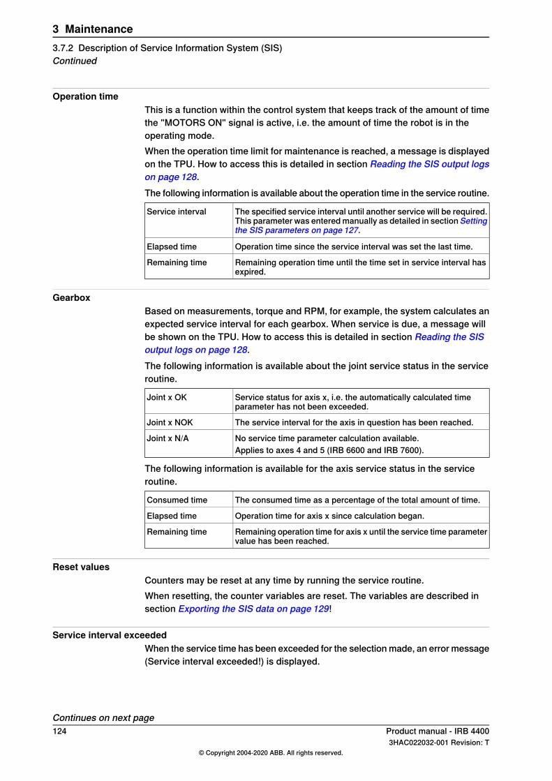
Operation timeThis is a function within the control system that keeps track of the amount of timethe "MOTORS ON" signal is active, i.e. the amount of time the robot is in theoperating mode.When the operation time limit for maintenance is reached, a message is displayedon the TPU. How to access this is detailed in section Reading the SIS output logson page 128.The following information is available about the operation time in the service routine.
The specified service interval until another service will be required.This parameter was entered manually as detailed in section Settingthe SIS parameters on page 127.
Service interval
Operation time since the service interval was set the last time.Elapsed time
Remaining operation time until the time set in service interval hasexpired.
Remaining time
GearboxBased on measurements, torque and RPM, for example, the system calculates anexpected service interval for each gearbox. When service is due, a message willbe shown on the TPU. How to access this is detailed in section Reading the SISoutput logs on page 128.The following information is available about the joint service status in the serviceroutine.
Service status for axis x, i.e. the automatically calculated timeparameter has not been exceeded.
Joint x OK
The service interval for the axis in question has been reached.Joint x NOK
No service time parameter calculation available.Joint x N/AApplies to axes 4 and 5 (IRB 6600 and IRB 7600).
The following information is available for the axis service status in the serviceroutine.
The consumed time as a percentage of the total amount of time.Consumed time
Operation time for axis x since calculation began.Elapsed time
Remaining operation time for axis x until the service time parametervalue has been reached.
Remaining time
Reset valuesCounters may be reset at any time by running the service routine.When resetting, the counter variables are reset. The variables are described insection Exporting the SIS data on page 129!
Service interval exceededWhen the service time has been exceeded for the selection made, an error message(Service interval exceeded!) is displayed.
Continues on next page124 Product manual - IRB 4400
3HAC022032-001 Revision: T© Copyright 2004-2020 ABB. All rights reserved.
3 Maintenance3.7.2 Description of Service Information System (SIS)Continued
No data availableWhen no data is available for the selection made, a message (No data available!)is displayed when trying to display the data.
Product manual - IRB 4400 1253HAC022032-001 Revision: T
© Copyright 2004-2020 ABB. All rights reserved.
3 Maintenance3.7.2 Description of Service Information System (SIS)
Continued
3.7.3 SIS system parameters
GeneralThis section details the system parameters that may be set with estimated values.The values can be defined by the operating organization as knowledge of therobot's working conditions are accumulated.Since the counters are to be used for purposes defined by the user, ABB cannotgive any recommendations regarding their definitions.
Operation time limit (service level)The number of operation hours selected as service interval.E.g. by setting the value "20,000", the SIS will save this as the nominal time foractivating the alarm, not counting the percentage described below.
Operation time warningA percentage of the "Operation time limit" specified above.E.g. by setting the value "90", the SIS will alert the operator 18,000 hours after anoperation time "Reset" was made the last time.
Calendar time limit (service level)The number of calendar years selected as service interval.E.g. by setting the value "2", the SIS will save this as the nominal time for activatingthe alarm, not counting the percentage described below.
Calendar time warningA percentage of the "Calendar time limit" specified above.E.g. by setting the value "90", the SIS will alert the operator after 90% of two years,i.e. 657 days after a calendar time "Reset" was made the last time.
Gearbox warningA percentage of the gearbox service interval as calculated by the system. E.g. bysetting the value "90", the SIS will alert the operator after 90% of the expectedservice interval of each gearbox.The robot system automatically detects and stores all required variables to calculatethe expected service interval (estimated remaining lifetime) of each gearbox. Thisis done by extrapolating data from earlier operation into a function of time, usinga formula including:
• input and output torque• gearbox spindle speed• other variables
126 Product manual - IRB 44003HAC022032-001 Revision: T
© Copyright 2004-2020 ABB. All rights reserved.
3 Maintenance3.7.3 SIS system parameters
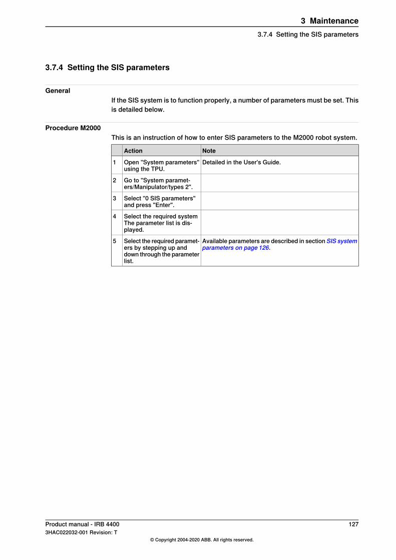
3.7.4 Setting the SIS parameters
GeneralIf the SIS system is to function properly, a number of parameters must be set. Thisis detailed below.
Procedure M2000This is an instruction of how to enter SIS parameters to the M2000 robot system.
NoteAction
Detailed in the User's Guide.Open "System parameters"using the TPU.
1
Go to "System paramet-ers/Manipulator/types 2".
2
Select "0 SIS parameters"and press "Enter".
3
Select the required systemThe parameter list is dis-played.
4
Available parameters are described in section SIS systemparameters on page 126.
Select the required paramet-ers by stepping up anddown through the parameterlist.
5
Product manual - IRB 4400 1273HAC022032-001 Revision: T
© Copyright 2004-2020 ABB. All rights reserved.
3 Maintenance3.7.4 Setting the SIS parameters
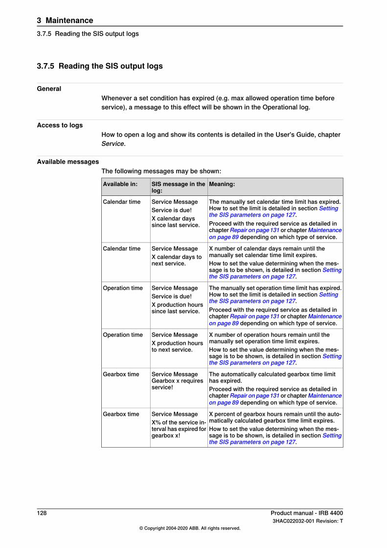
3.7.5 Reading the SIS output logs
GeneralWhenever a set condition has expired (e.g. max allowed operation time beforeservice), a message to this effect will be shown in the Operational log.
Access to logsHow to open a log and show its contents is detailed in the User's Guide, chapterService.
Available messagesThe following messages may be shown:
Meaning:SIS message in thelog:
Available in:
The manually set calendar time limit has expired.How to set the limit is detailed in section Settingthe SIS parameters on page 127.
Service MessageService is due!X calendar dayssince last service.
Calendar time
Proceed with the required service as detailed inchapterRepair on page131 or chapterMaintenanceon page 89 depending on which type of service.
X number of calendar days remain until themanually set calendar time limit expires.
Service MessageX calendar days tonext service.
Calendar time
How to set the value determining when the mes-sage is to be shown, is detailed in section Settingthe SIS parameters on page 127.
The manually set operation time limit has expired.How to set the limit is detailed in section Settingthe SIS parameters on page 127.
Service MessageService is due!X production hourssince last service.
Operation time
Proceed with the required service as detailed inchapterRepair on page131 or chapterMaintenanceon page 89 depending on which type of service.
X number of operation hours remain until themanually set operation time limit expires.
Service MessageX production hoursto next service.
Operation time
How to set the value determining when the mes-sage is to be shown, is detailed in section Settingthe SIS parameters on page 127.
The automatically calculated gearbox time limithas expired.
Service MessageGearbox x requiresservice!
Gearbox time
Proceed with the required service as detailed inchapterRepair on page131 or chapterMaintenanceon page 89 depending on which type of service.
X percent of gearbox hours remain until the auto-matically calculated gearbox time limit expires.
Service MessageX% of the service in-terval has expired forgearbox x!
Gearbox time
How to set the value determining when the mes-sage is to be shown, is detailed in section Settingthe SIS parameters on page 127.
128 Product manual - IRB 44003HAC022032-001 Revision: T
© Copyright 2004-2020 ABB. All rights reserved.
3 Maintenance3.7.5 Reading the SIS output logs
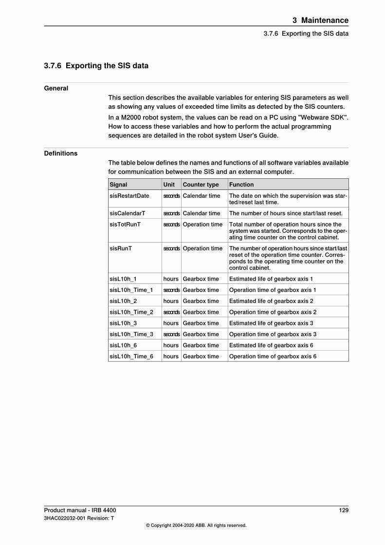
3.7.6 Exporting the SIS data
GeneralThis section describes the available variables for entering SIS parameters as wellas showing any values of exceeded time limits as detected by the SIS counters.In a M2000 robot system, the values can be read on a PC using "Webware SDK".How to access these variables and how to perform the actual programmingsequences are detailed in the robot system User's Guide.
DefinitionsThe table below defines the names and functions of all software variables availablefor communication between the SIS and an external computer.
FunctionCounter typeUnitSignal
The date on which the supervision was star-ted/reset last time.
Calendar timesecondssisRestartDate
The number of hours since start/last reset.Calendar timesecondssisCalendarT
Total number of operation hours since thesystem was started. Corresponds to the oper-ating time counter on the control cabinet.
Operation timesecondssisTotRunT
The number of operation hours since start/lastreset of the operation time counter. Corres-ponds to the operating time counter on thecontrol cabinet.
Operation timesecondssisRunT
Estimated life of gearbox axis 1Gearbox timehourssisL10h_1
Operation time of gearbox axis 1Gearbox timesecondssisL10h_Time_1
Estimated life of gearbox axis 2Gearbox timehourssisL10h_2
Operation time of gearbox axis 2Gearbox timesecondssisL10h_Time_2
Estimated life of gearbox axis 3Gearbox timehourssisL10h_3
Operation time of gearbox axis 3Gearbox timesecondssisL10h_Time_3
Estimated life of gearbox axis 6Gearbox timehourssisL10h_6
Operation time of gearbox axis 6Gearbox timehourssisL10h_Time_6
Product manual - IRB 4400 1293HAC022032-001 Revision: T
© Copyright 2004-2020 ABB. All rights reserved.
3 Maintenance3.7.6 Exporting the SIS data

This page is intentionally left blank
4 Repair4.1 Introduction
Structure of this chapterThis chapter describes repair activities for the IRB 4400. Each procedure containsthe information required to perform the activity, for example spare parts numbers,required special tools, and materials.
WARNING
Repair activities not described in this chapter must only be carried out by ABB.
Report replaced units
Note
When replacing a part on the IRB 4400, report to your local ABB the serial number,the article number, and the revision of both the replaced unit and the replacementunit.This is particularly important for safety equipment to maintain the safety integrityof the installation.
Safety informationMake sure to read through the chapter Safety on page 17 before commencing anyservice work.
Note
If the IRB 4400 is connected to power, always make sure that the IRB 4400 isconnected to protective earth and a residual current device (RCD) before startingany repair work.For more information see:
• Product manual - IRC5• Product manual - IRC5 Panel Mounted Controller
Product manual - IRB 4400 1313HAC022032-001 Revision: T
© Copyright 2004-2020 ABB. All rights reserved.
4 Repair4.1 Introduction
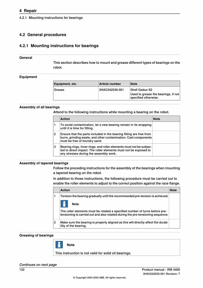
4.2 General procedures
4.2.1 Mounting instructions for bearings
GeneralThis section describes how to mount and grease different types of bearings on therobot.
Equipment
NoteArticle numberEquipment, etc.
Shell Gadus S23HAC042536-001GreaseUsed to grease the bearings, if notspecified otherwise.
Assembly of all bearingsAttend to the following instructions while mounting a bearing on the robot.
NoteAction
To avoid contamination, let a new bearing remain in its wrappinguntil it is time for fitting.
1
Ensure that the parts included in the bearing fitting are free fromburrs, grinding waste, and other contamination. Cast componentsmust be free of foundry sand.
2
Bearing rings, inner rings, and roller elements must not be subjec-ted to direct impact. The roller elements must not be exposed toany stresses during the assembly work.
3
Assembly of tapered bearingsFollow the preceding instructions for the assembly of the bearings when mountinga tapered bearing on the robot.In addition to those instructions, the following procedure must be carried out toenable the roller elements to adjust to the correct position against the race flange.
NoteAction
Tension the bearing gradually until the recommended pre-tension is achieved.
Note
The roller elements must be rotated a specified number of turns before pre-tensioning is carried out and also rotated during the pre-tensioning sequence.
1
Make sure the bearing is properly aligned as this will directly affect the durab-ility of the bearing.
2
Greasing of bearings
Note
This instruction is not valid for solid oil bearings.
Continues on next page132 Product manual - IRB 4400
3HAC022032-001 Revision: T© Copyright 2004-2020 ABB. All rights reserved.
4 Repair4.2.1 Mounting instructions for bearings
The bearings must be greased after assembly according to the followinginstructions:
• The bearings must not be completely filled with grease. However, if spaceis available beside the bearing fitting, the bearing may be totally filled withgrease when mounted, as excessive grease will be pressed out from thebearing when the robot is started.
• During operation, the bearing should be filled to 70-80% of the availablevolume.
• Ensure that grease is handled and stored properly to avoid contamination.Grease the different types of bearings as following description:
• Grooved ball bearings must be filled with grease from both sides.• Tapered roller bearings and axial needle bearings must be greased in the
split condition.
Product manual - IRB 4400 1333HAC022032-001 Revision: T
© Copyright 2004-2020 ABB. All rights reserved.
4 Repair4.2.1 Mounting instructions for bearings
Continued
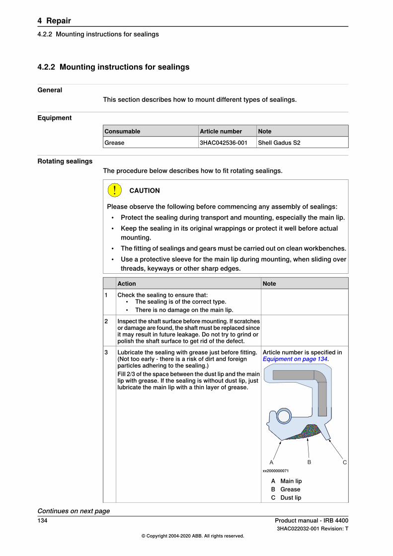
4.2.2 Mounting instructions for sealings
GeneralThis section describes how to mount different types of sealings.
Equipment
NoteArticle numberConsumable
Shell Gadus S23HAC042536-001Grease
Rotating sealingsThe procedure below describes how to fit rotating sealings.
CAUTION
Please observe the following before commencing any assembly of sealings:• Protect the sealing during transport and mounting, especially the main lip.• Keep the sealing in its original wrappings or protect it well before actual
mounting.• The fitting of sealings and gears must be carried out on clean workbenches.• Use a protective sleeve for the main lip during mounting, when sliding over
threads, keyways or other sharp edges.
NoteAction
Check the sealing to ensure that:• The sealing is of the correct type.• There is no damage on the main lip.
1
Inspect the shaft surface before mounting. If scratchesor damage are found, the shaft must be replaced sinceit may result in future leakage. Do not try to grind orpolish the shaft surface to get rid of the defect.
2
Article number is specified inEquipment on page 134.
A B C
xx2000000071
A Main lipB GreaseC Dust lip
Lubricate the sealing with grease just before fitting.(Not too early - there is a risk of dirt and foreignparticles adhering to the sealing.)Fill 2/3 of the space between the dust lip and the mainlip with grease. If the sealing is without dust lip, justlubricate the main lip with a thin layer of grease.
3
Continues on next page134 Product manual - IRB 4400
3HAC022032-001 Revision: T© Copyright 2004-2020 ABB. All rights reserved.
4 Repair4.2.2 Mounting instructions for sealings
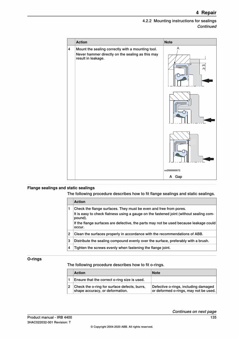
NoteActionA
xx2000000072
A Gap
Mount the sealing correctly with a mounting tool.Never hammer directly on the sealing as this mayresult in leakage.
4
Flange sealings and static sealingsThe following procedure describes how to fit flange sealings and static sealings.
Action
Check the flange surfaces. They must be even and free from pores.1It is easy to check flatness using a gauge on the fastened joint (without sealing com-pound).If the flange surfaces are defective, the parts may not be used because leakage couldoccur.
Clean the surfaces properly in accordance with the recommendations of ABB.2
Distribute the sealing compound evenly over the surface, preferably with a brush.3
Tighten the screws evenly when fastening the flange joint.4
O-ringsThe following procedure describes how to fit o-rings.
NoteAction
Ensure that the correct o-ring size is used.1
Defective o-rings, including damagedor deformed o-rings, may not be used.
Check the o-ring for surface defects, burrs,shape accuracy, or deformation.
2
Continues on next pageProduct manual - IRB 4400 1353HAC022032-001 Revision: T
© Copyright 2004-2020 ABB. All rights reserved.
4 Repair4.2.2 Mounting instructions for sealings
Continued
NoteAction
Check the o-ring grooves.3The grooves must be geometrically correct andshould be free of pores and contamination.
Lubricate the o-ring with grease.4
Tighten the screws evenly while assembling.5
Check that the o-ring is not squashed outsidethe o-ring groove.
6
136 Product manual - IRB 44003HAC022032-001 Revision: T
© Copyright 2004-2020 ABB. All rights reserved.
4 Repair4.2.2 Mounting instructions for sealingsContinued
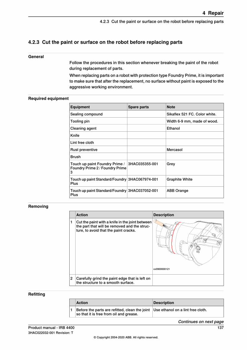
4.2.3 Cut the paint or surface on the robot before replacing parts
GeneralFollow the procedures in this section whenever breaking the paint of the robotduring replacement of parts.When replacing parts on a robot with protection type Foundry Prime, it is importantto make sure that after the replacement, no surface without paint is exposed to theaggressive working environment.
Required equipment
NoteSpare partsEquipment
Sikaflex 521 FC. Color white.Sealing compound
Width 6-9 mm, made of wood.Tooling pin
EthanolCleaning agent
Knife
Lint free cloth
MercasolRust preventive
Brush
Grey3HAC035355-001Touch up paint Foundry Prime /Foundry Prime 2 / Foundry Prime3
Graphite White3HAC067974-001Touch up paint Standard/FoundryPlus
ABB Orange3HAC037052-001Touch up paint Standard/FoundryPlus
Removing
DescriptionAction
xx0900000121
Cut the paint with a knife in the joint betweenthe part that will be removed and the struc-ture, to avoid that the paint cracks.
1
Carefully grind the paint edge that is left onthe structure to a smooth surface.
2
Refitting
DescriptionAction
Use ethanol on a lint free cloth.Before the parts are refitted, clean the jointso that it is free from oil and grease.
1
Continues on next pageProduct manual - IRB 4400 1373HAC022032-001 Revision: T
© Copyright 2004-2020 ABB. All rights reserved.
4 Repair4.2.3 Cut the paint or surface on the robot before replacing parts
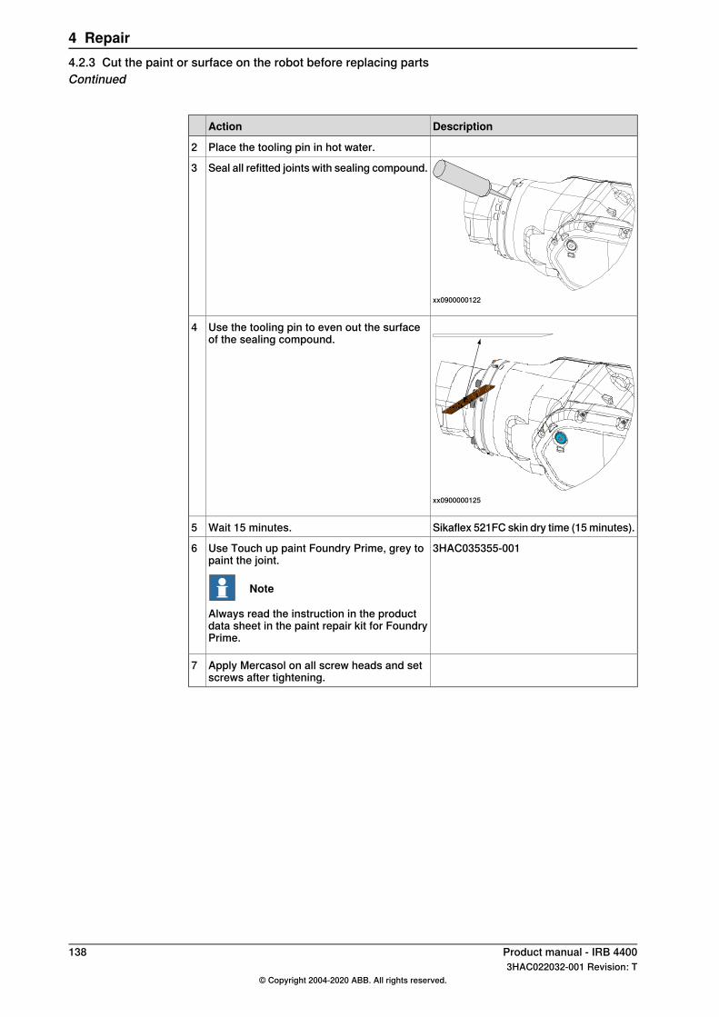
DescriptionAction
Place the tooling pin in hot water.2
xx0900000122
Seal all refitted joints with sealing compound.3
xx0900000125
Use the tooling pin to even out the surfaceof the sealing compound.
4
Sikaflex 521FC skin dry time (15 minutes).Wait 15 minutes.5
3HAC035355-001Use Touch up paint Foundry Prime, grey topaint the joint.
Note
Always read the instruction in the productdata sheet in the paint repair kit for FoundryPrime.
6
Apply Mercasol on all screw heads and setscrews after tightening.
7
138 Product manual - IRB 44003HAC022032-001 Revision: T
© Copyright 2004-2020 ABB. All rights reserved.
4 Repair4.2.3 Cut the paint or surface on the robot before replacing partsContinued
4.2.4 Performing a leak-down test
When to perform a leak-down testAfter refitting any motor and gearbox, the integrity of all seals enclosing the gearboxoil must be tested. This is done in a leak-down test.
Required equipment
NoteArticle numberEquipment, etc.
-Leak-down tester
-Leak detection spray
Performing a leak-down test
NoteAction
Finish the refitting procedure of the motor or gear inquestion.
1
Remove the upper oil plug on the gear and replaceit with the leak-down tester.
2
Regulators, which are included in the leak-down test,may be required.
Correct value:Use caution, apply compressed air and raise thepressure with the knob until the correct value isshown on the manometer.
CAUTION
The pressure must under no circumstance be higherthan 0.25 bar (20-25 kPa). Also during the time whenthe pressure is raised.
30.2-0.25 bar (20-25 kPa)
Disconnect the compressed air supply.4
If the compressed air is signific-antly colder or warmer than thegearbox to be tested, a slightpressure increase or decreasemay occur. This is quite normal.
Wait for approximately 8-10 minutes and make surethat no pressure loss occurs.
5
If any pressure drop occurred, then localize the leakas described in step 7.
6
If no pressure drop occurred, then remove the leak-down tester and refit the oil plug. The test is complete.
Spray any suspected leak areas with the leak detec-tion spray. Bubbles indicate a leak.
7
When the leak has been localized, take the necessarymeasures to correct the leak.
8
Product manual - IRB 4400 1393HAC022032-001 Revision: T
© Copyright 2004-2020 ABB. All rights reserved.
4 Repair4.2.4 Performing a leak-down test
4.2.5 The brake release buttons may be jammed after service work
DescriptionThe brake release unit has push-buttons for the brake release of each axis motor.When service work is performed inside the SMB recess that includes removal andrefitting of the brake release unit, the brake release buttons may be jammed afterrefitting.
DANGER
If the power is turned on while a brake release button is jammed in depressedposition, the affected motor brake is released. This may cause serious personalinjuries and damage to the robot.
EliminationTo eliminate the danger after service work has been performed inside the SMBrecess, follow the procedure below.
Action
Make sure the power is turned off.1
Remove the push-button guard, if necessary.2
Verify that the push-buttons of the brake release unit are working by pressing themdown, one by one.
3
Make sure none of the buttons are jammed in the tube.
If a button gets jammed in the depressed position, the alignment of the brake releaseunit must be adjusted so that the buttons can move freely in their tubes.
4
140 Product manual - IRB 44003HAC022032-001 Revision: T
© Copyright 2004-2020 ABB. All rights reserved.
4 Repair4.2.5 The brake release buttons may be jammed after service work
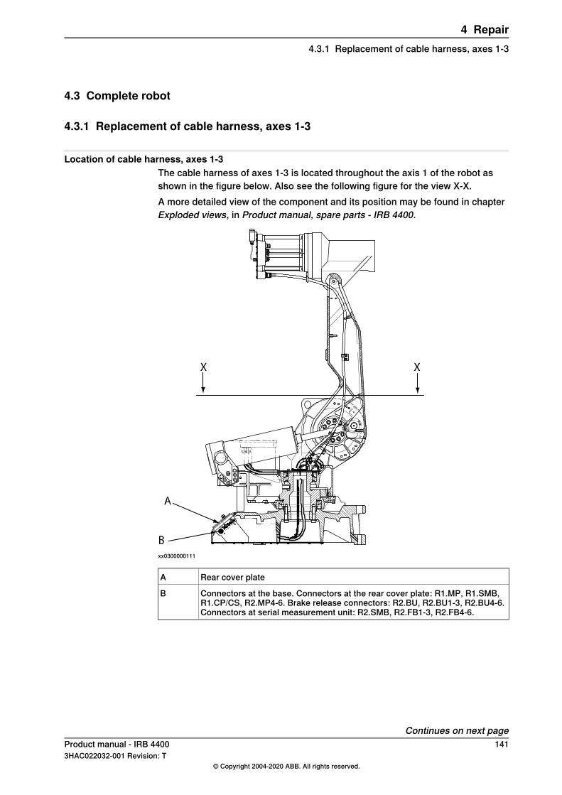
4.3 Complete robot
4.3.1 Replacement of cable harness, axes 1-3
Location of cable harness, axes 1-3The cable harness of axes 1-3 is located throughout the axis 1 of the robot asshown in the figure below. Also see the following figure for the view X-X.A more detailed view of the component and its position may be found in chapterExploded views, in Product manual, spare parts - IRB 4400.
xx0300000111
Rear cover plateA
Connectors at the base. Connectors at the rear cover plate: R1.MP, R1.SMB,R1.CP/CS, R2.MP4-6. Brake release connectors: R2.BU, R2.BU1-3, R2.BU4-6.Connectors at serial measurement unit: R2.SMB, R2.FB1-3, R2.FB4-6.
B
Continues on next pageProduct manual - IRB 4400 1413HAC022032-001 Revision: T
© Copyright 2004-2020 ABB. All rights reserved.
4 Repair4.3.1 Replacement of cable harness, axes 1-3
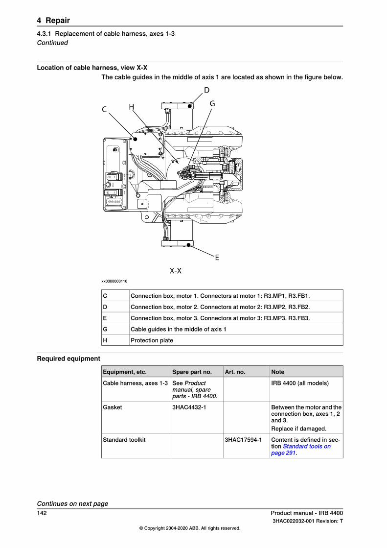
Location of cable harness, view X-XThe cable guides in the middle of axis 1 are located as shown in the figure below.
xx0300000110
Connection box, motor 1. Connectors at motor 1: R3.MP1, R3.FB1.C
Connection box, motor 2. Connectors at motor 2: R3.MP2, R3.FB2.D
Connection box, motor 3. Connectors at motor 3: R3.MP3, R3.FB3.E
Cable guides in the middle of axis 1G
Protection plateH
Required equipment
NoteArt. no.Spare part no.Equipment, etc.
IRB 4400 (all models)See Productmanual, spareparts - IRB 4400.
Cable harness, axes 1-3
Between the motor and theconnection box, axes 1, 2and 3.
3HAC4432-1Gasket
Replace if damaged.
Content is defined in sec-tion Standard tools onpage 291.
3HAC17594-1Standard toolkit
Continues on next page142 Product manual - IRB 4400
3HAC022032-001 Revision: T© Copyright 2004-2020 ABB. All rights reserved.
4 Repair4.3.1 Replacement of cable harness, axes 1-3Continued
NoteArt. no.Spare part no.Equipment, etc.
These procedures includereferences to the tools re-quired.
Other tools and proced-ures may be required.See references to theseprocedures in the step-by-step instructions be-low.
See chapter Circuit dia-gram on page 297.
Circuit diagram
General calibration inform-ation is included in sectionCalibration on page 259.
Calibration Pendulum In-struction
CAUTION
Always cut the paint with a knife and grind the paint edge when disassemblingparts. SeeCut the paint or surface on the robot before replacing parts on page137.
Removal, cabling axes 1-3The procedure below details how to remove the cable harness from the axes 1-3.
Info/IllustrationAction
DANGER
Turn off all:• electric power supply• hydraulic pressure supply• air pressure supply (do not turn off for Foundry
Prime robots!)to the robot, before entering the robot working area.
1
Shown in the figure Locationof cable harness, axes 1-3 onpage 141.
Remove the rear cover plate.2
Removal detailed in sectionRemoval, serial measurementunit on page 205.
Remove the serial measurement unit.3
Shown in the figure Locationof cable harness, axes 1-3 onpage 141.
Loosen the connectors R1.MP1, R2.FB1-3, R2.BU,R2.BU1-3. Also loosen the earth connections.
4
Cut all the ties around bundle.5
Remove the cable bracket inside the base.6
Shown in the figure Locationof cable harness, view X-X onpage 142.
Remove the cable guides and the protection plate in themiddle of axis 1.
7
Remove the covers from the connections boxes for themotors in axes 1-2-3.
8
Shown in the figure Locationof cable harness, view X-X onpage 142.
Loosen all the connectors to the motors of axes 1-2-3.9
Remove the connection boxes from the motors 1-2-3.10
Continues on next pageProduct manual - IRB 4400 1433HAC022032-001 Revision: T
© Copyright 2004-2020 ABB. All rights reserved.
4 Repair4.3.1 Replacement of cable harness, axes 1-3
Continued
Info/IllustrationAction
Feed the cabling up through the middle of axis 1 andremove the complete cabling.Tip! Gather the loose cabling and connectors into apackage with tape in order to protect the connectors andmake the cabling easier to handle.
11
Refitting, cabling axes 1-3The procedure below details how to refit the cable harness to axes 1-3.
Info/IllustrationAction
DANGER
Turn off all:• electric power supply• hydraulic pressure supply• air pressure supply (do not turn off for Foundry
Prime robots!)to the robot, before entering the robot working area.
1
Part no. is specified in Re-quired equipment on page142
Feed the cable harness, axes 1-3 through the protectionplate and down through the middle of axis 1.
Tip
Gather the loose cabling and connectors into a packagewith tape in order to protect the connectors and makethe cabling easier to handle.
2
Part no. is specified in Re-quired equipment on page142
Refit the connection boxes to the motors 1-2-3. Replacethe gaskets if they are damaged.
3
Shown in the figure Locationof cable harness, view X-X onpage 142
Reconnect the connectors in the motors 1-2-3.4
Shown in the figure Locationof cable harness, view X-X onpage 142
Refit the cable guide and the protection plate in themiddle of axis 1.
5
See chapter Exploded views,in Product manual, spareparts - IRB 4400.
Secure the cabling with straps, according to foldout 3.6
Refit the cable bracket inside the base.7
See chapter Exploded views,in Product manual, spareparts - IRB 4400.
Reposition the cabling inside the base according to fol-dout 4.
8
Reconnect all connectors at the base.9
This is detailed in section Re-fitting, serial measurement uniton page 206.
Refit the serial measurement unit.10
Shown in the figure Locationof cable harness, axes 1-3 onpage 141
Refit the rear cover plate.11
Refit the covers of the connection boxes.12
Continues on next page144 Product manual - IRB 4400
3HAC022032-001 Revision: T© Copyright 2004-2020 ABB. All rights reserved.
4 Repair4.3.1 Replacement of cable harness, axes 1-3Continued
Info/IllustrationAction
Calibration is detailed in aseparate calibration manualenclosed with the calibrationtools.
Recalibrate the robot!13
General calibration informationis included in section Calibra-tion on page 259.
DANGER
Make sure all safety requirements are met when perform-ing the first test run.
14
Product manual - IRB 4400 1453HAC022032-001 Revision: T
© Copyright 2004-2020 ABB. All rights reserved.
4 Repair4.3.1 Replacement of cable harness, axes 1-3
Continued
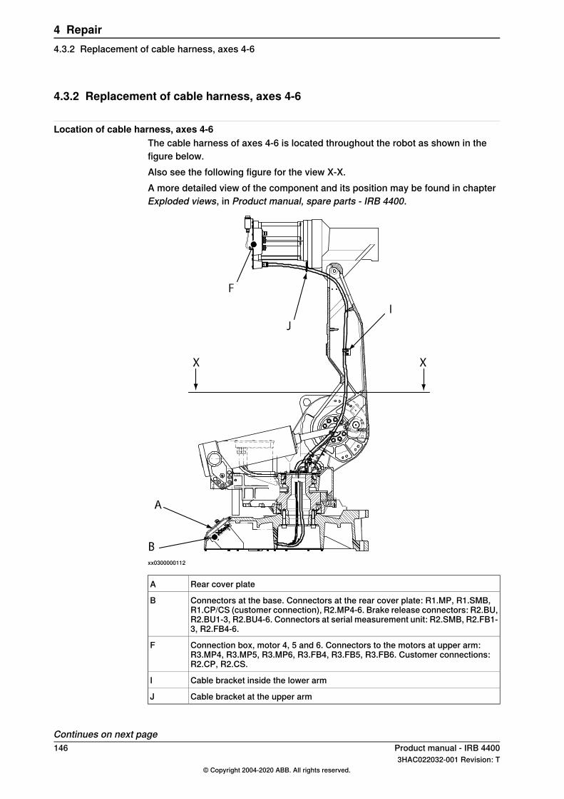
4.3.2 Replacement of cable harness, axes 4-6
Location of cable harness, axes 4-6The cable harness of axes 4-6 is located throughout the robot as shown in thefigure below.Also see the following figure for the view X-X.A more detailed view of the component and its position may be found in chapterExploded views, in Product manual, spare parts - IRB 4400.
xx0300000112
Rear cover plateA
Connectors at the base. Connectors at the rear cover plate: R1.MP, R1.SMB,R1.CP/CS (customer connection), R2.MP4-6. Brake release connectors: R2.BU,R2.BU1-3, R2.BU4-6. Connectors at serial measurement unit: R2.SMB, R2.FB1-3, R2.FB4-6.
B
Connection box, motor 4, 5 and 6. Connectors to the motors at upper arm:R3.MP4, R3.MP5, R3.MP6, R3.FB4, R3.FB5, R3.FB6. Customer connections:R2.CP, R2.CS.
F
Cable bracket inside the lower armI
Cable bracket at the upper armJ
Continues on next page146 Product manual - IRB 4400
3HAC022032-001 Revision: T© Copyright 2004-2020 ABB. All rights reserved.
4 Repair4.3.2 Replacement of cable harness, axes 4-6
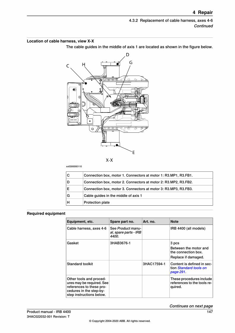
Location of cable harness, view X-XThe cable guides in the middle of axis 1 are located as shown in the figure below.
xx0300000110
Connection box, motor 1. Connectors at motor 1: R3.MP1, R3.FB1.C
Connection box, motor 2. Connectors at motor 2: R3.MP2, R3.FB2.D
Connection box, motor 3. Connectors at motor 3: R3.MP3, R3.FB3.E
Cable guides in the middle of axis 1G
Protection plateH
Required equipment
NoteArt. no.Spare part no.Equipment, etc.
IRB 4400 (all models)See Product manu-al, spare parts - IRB4400.
Cable harness, axes 4-6
3 pcs3HAB3676-1GasketBetween the motor andthe connection box.Replace if damaged.
Content is defined in sec-tion Standard tools onpage 291.
3HAC17594-1Standard toolkit
These procedures includereferences to the tools re-quired.
Other tools and proced-ures may be required. Seereferences to these pro-cedures in the step-by-step instructions below.
Continues on next pageProduct manual - IRB 4400 1473HAC022032-001 Revision: T
© Copyright 2004-2020 ABB. All rights reserved.
4 Repair4.3.2 Replacement of cable harness, axes 4-6
Continued

NoteArt. no.Spare part no.Equipment, etc.
See chapter Circuit dia-gram on page 297.
Circuit diagram
Calibration is detailed in aseparate calibrationmanual enclosed with thecalibration tools.
Calibration Pendulum In-struction
Art. no. is specified insection on page ? in part2 of the Product manual.
CAUTION
Always cut the paint with a knife and grind the paint edge when disassemblingparts. SeeCut the paint or surface on the robot before replacing parts on page137.
Removal, cabling axes 4-6The procedure below details how to remove the cable harness from the axes 4-6.
Info/IllustrationAction
DANGER
Turn off all:• electric power supply• hydraulic pressure supply• air pressure supply (do not turn off for
Foundry Prime robots!)to the robot, before entering the robot work-ing area.
1
Remove the cover ot the connection box formotors 4-5-6.
2
Shown in the figure Location of cableharness, axes 4-6 on page 146
Remove the rear cover plate.3
Detailed in section Removal, serialmeasurement unit on page 205
Remove the serial measurement unit.4
Shown in the figure Location of cableharness, axes 4-6 on page 146
Loosen the connectors R2.MP4-6, R2.FB4-6,R2.BU4-6, R1.CP/CS. Also loosen the earthconnections.
5
Cut all the straps around the bundle.6
Remove the cable bracket inside the base.7
Shown in the figureLocation of cable har-ness, view X-X on page 147
Remove the cable guides and the protectionplate in the midle of axis 1.
8
Continues on next page148 Product manual - IRB 4400
3HAC022032-001 Revision: T© Copyright 2004-2020 ABB. All rights reserved.
4 Repair4.3.2 Replacement of cable harness, axes 4-6Continued

Info/IllustrationAction
xx0300000113
Loosen the cable brackets (A) betweengearboxes 2 and 3 and cut the strap aroundthem.
9
Feed the cabling and the air hose, if any, upthrough axis 1.
Tip
Gather the loose cabling and connectors intoa package with tape in order to protect theconnectors and make the cabling easier tohandle.
10
Shown in the figure Location of cableharness, axes 4-6 on page 146
Loosen the cable bracket inside the lowerarm and undo the two screws.
11
Shown in the figure Location of cableharness, axes 4-6 on page 146
Loosen the cable bracket at the upper arm.12
Shown in the figure Location of cableharness, axes 4-6 on page 146
Loosen all the connectors to the motors atthe upper arm and customer connections, ifany.
13
Remove the connection box together with thecabling.
14
Continues on next pageProduct manual - IRB 4400 1493HAC022032-001 Revision: T
© Copyright 2004-2020 ABB. All rights reserved.
4 Repair4.3.2 Replacement of cable harness, axes 4-6
Continued

Connection box, upper armThe figure below shows the location of the motors, connectors and cabling in theupper arm connection box.
xx0300000116
Axis 4 motorA
Connector R3.MP4A1
Connector R3.FB4A2
Axis 5 motorB
Connector R3.MP5B1
Connector R3.FB5B2
Axis 6 motorC
Connector R3.MP6C1
Connector R3.FB6C2
Protection plateD
Cable strap, indoorE
cable strap, outdoorF
Continues on next page150 Product manual - IRB 4400
3HAC022032-001 Revision: T© Copyright 2004-2020 ABB. All rights reserved.
4 Repair4.3.2 Replacement of cable harness, axes 4-6Continued

Refitting, cabling axes 4-6The procedure below details how to refit the cable harness to the axes 4-6.
Info/IllustrationAction
DANGER
Turn off all:• electric power supply• hydraulic pressure supply• air pressure supply (do not turn off for
Foundry Prime robots!)to the robot, before entering the robot workingarea.
1
Part no. is specified in Requiredequipment on page 147.
Check the position of the three gaskets, locatedbetween the motors and the connection box. Re-place them if damaged.
2
Refit the connection box.3Make sure the gaskets are seated properly!
Connectors and correct positioningare shown in the figure Connectionbox, upper arm on page 150.
Reconnect all the connectors and reposition thecabling inside the connection box using straps.
4
Shown in the figureConnection box,upper arm on page 150.
Refit the protection plate in the connection box.5
Run the cabling through the lower arm.6
Shown in the figure Location of cableharness, axes 4-6 on page 146.
Refit the cable bracket at the upper arm.7
Shown in the figure Location of cableharness, axes 4-6 on page 146.
Refit the cable bracket inside the lower arm.8
Shown in the figure Location of cableharness, view X-X on page 147.
Feed the cabling through the protection plate anddown through the axis 1.
9
xx0300000113
Refit the cable brackets (A) between the gearboxesof axes 2 and 3 and strap the cabling.
10
Refit the cable bracket inside the base.11
See chapter Exploded views, inProduct manual, spare parts - IRB4400.
Put straps around the bundle and position thecabling at the base according to foldout 4.
12
Reconnect all the connectors at the base.13
Continues on next pageProduct manual - IRB 4400 1513HAC022032-001 Revision: T
© Copyright 2004-2020 ABB. All rights reserved.
4 Repair4.3.2 Replacement of cable harness, axes 4-6
Continued

Info/IllustrationAction
Detailed inRefitting, serial measure-ment unit on page 206.
Refit the serial measurement unit.14
Shown in the figure Location of cableharness, axes 4-6 on page 146.
Refit the rear cover plate.15
Refit the cover of the connection box in the upperarm.
16
Calibration is detailed in a separatecalibration manual enclosed with thecalibration tools.
Recalibrate the robot!17
General calibration information isincluded in section Calibration onpage 259.
DANGER
Make sure all safety requirements are met whenperforming the first test run.
18
152 Product manual - IRB 44003HAC022032-001 Revision: T
© Copyright 2004-2020 ABB. All rights reserved.
4 Repair4.3.2 Replacement of cable harness, axes 4-6Continued

4.3.3 Replacement of complete arm system
Location of complete arm systemThe complete arm system includes the lower arm and the complete upper arm, asshown in the figure below.A more detailed view of the component and its position may be found in chapterExploded views, in Product manual, spare parts - IRB 4400.
xx0300000143
Lower armA
Upper armB
Attachment screws and friction washers, lower armC
Parallel armD
V-ring between lower arm and gearbox axis 3E
Required equipment
NoteArt. no.Spare part no.Equipment, etc.
2 pcs.3HAB3773-11V-ringOn both sides of the lowerarm, in the frame.
Used to grease sealings andbearings.
3HAC042536-001
Grease
Content is defined in sectionStandard tools on page 291.
3HAC17594-1Standard toolkit
Continues on next pageProduct manual - IRB 4400 1533HAC022032-001 Revision: T
© Copyright 2004-2020 ABB. All rights reserved.
4 Repair4.3.3 Replacement of complete arm system

NoteArt. no.Spare part no.Equipment, etc.
These procedures include ref-erences to the tools required.
Other tools and proceduresmay be required. See refer-ences to these proceduresin the step-by-step instruc-tions below.
General calibration informa-tion is included in sectionCalibration on page 259.
Calibration Pendulum In-struction
CAUTION
Always cut the paint with a knife and grind the paint edge when disassemblingparts. SeeCut the paint or surface on the robot before replacing parts on page137.
Removal, complete arm systemThe procedure below details how to remove the complete arm system from therobot.
Info/IllustrationAction
DANGER
Turn off all:• electric power supply• hydraulic pressure supply• air pressure supply (do not turn off for
Foundry Prime robots!)to the robot, before entering the robot work-ing area.
1
CAUTION
The robot arm system weighs 245 kg.All lifting accessories used must be sizedaccordingly!
2
Detailed in sectionReplacement of tie rodon page 187.
Remove the tie rod.3
Detailed in section Replacement of com-plete arm system on page 153.
Remove the cabling down to axis 1.4
Continues on next page154 Product manual - IRB 4400
3HAC022032-001 Revision: T© Copyright 2004-2020 ABB. All rights reserved.
4 Repair4.3.3 Replacement of complete arm systemContinued

Info/IllustrationAction
xx0300000142
Move the upper arm into a resting positionagainst the lower arm.Lock the upper arm in this position with se-curing slings around the lower and upper arm(A), as shown in the figure to the right.Note! If the arms are not properly secured,the upper arm may move during the lift andcause a drop of the complete arm system.
5
Note! The figure shows the IRB 4400.
Unload the weight of the arm system withlifting slings and a crane.
6
Detailed in section Removal, balancingdevice on page 197.
Remove the balancing device.7
Detailed in sectionReplacement of paral-lel arm / Replacement of bearing onpage 191.
Remove the parallel arm.8
Shown in the figure Location of completearm system on page 153.
Remove the attachment screws and frictionwashers, lower arm.
9
Lift away the complete arm system.Make sure the upper and lower arm areproperly secured to each other during the lift.
10
Refitting, complete arm systemThe procedure below details how to refit the complete arm system to the robot.
Info/IllustrationAction
DANGER
Turn off all:• electric power supply• hydraulic pressure supply• air pressure supply (do not turn off
for Foundry Prime robots!)to the robot, before entering the robotworking area.
1
Continues on next pageProduct manual - IRB 4400 1553HAC022032-001 Revision: T
© Copyright 2004-2020 ABB. All rights reserved.
4 Repair4.3.3 Replacement of complete arm system
Continued

Info/IllustrationAction
CAUTION
The robot arm system weighs 245 kg.All lifting accessories used must be sizedaccordingly!
2
Part no. is specified inRequired equipmenton page 153
Check and grease both of the V-rings in theframe. Replace if damaged.
3
xx0300000142
Lift the arm system into mounting position.Make sure the arms are properly securedto each other (A), as shown in the figure tothe right.
4
10 pcs, M16x55. Tightening torque: 260 Nm.Secure the arm system to the gearbox axis2 with the attachment screws and frictionwashers.
5Shown in the figure Location of completearm system on page 153
Make sure both V-rings are seated properly!
Grease the bearing seating of the parallelarm in the lower arm, to prevent clickingduring operation.
6
Detailed in section Refitting, parallelarm/bearing on page 193
Refit the parallel arm.7
Detailed in section Refitting of balancingdevice on page 200
Refit the balancing device.8
Move the upper arm to a horizontal position.9
Detailed in section Refitting, tie rod onpage 189
Refit the tie rod.10
Detailed in section Refitting, cabling axes4-6 on page 151
Refit the cabling to the upper arm.11
Continues on next page156 Product manual - IRB 4400
3HAC022032-001 Revision: T© Copyright 2004-2020 ABB. All rights reserved.
4 Repair4.3.3 Replacement of complete arm systemContinued

Info/IllustrationAction
Calibration is detailed in a separate calibra-tion manual enclosed with the calibrationtools.
Recalibrate the robot!12
General calibration information is includedin section Calibration on page 259.
DANGER
Make sure all safety requirements are metwhen performing the first test run.
13
Product manual - IRB 4400 1573HAC022032-001 Revision: T
© Copyright 2004-2020 ABB. All rights reserved.
4 Repair4.3.3 Replacement of complete arm system
Continued

4.4 Upper arm
4.4.1 Replacement of complete upper arm
Location of upper armThe complete upper arm includes the wrist unit and is located as shown in thefigure below. (The figure shows the IRB 4400.)A more detailed view of the component and its position may be found in chapterExploded views, in Product manual, spare parts - IRB 4400.
xx0300000129
Upper armA
Connectors of motors, axes 4, 5 and 6B
Connection box, upper armC
Calibration plate, axis 3D
VK coverE
KM nutF
ScrewG
BearingH
Sealing ringI
Shaft endJ
Continues on next page158 Product manual - IRB 4400
3HAC022032-001 Revision: T© Copyright 2004-2020 ABB. All rights reserved.
4 Repair4.4.1 Replacement of complete upper arm

Required equipment
NoteArt. no.Spare part no.Equipment, etc.
Foundry (also used for Stand-ard)
3HAC17542-1Upper arm, without wristand motors
Color: ABB Orange.
Foundry (also used for Stand-ard)
3HAC050860-001
Color: Graphite White
3HAC7877-1Sealing ring
3HAA2103-13Taper roller bearing
3HAC12165-1VK cover
3HAC4744-1Shaft end
Used to grease the bearing.3HAC042536-001
Grease
Loctite 243Locking liquid
Content is defined in sectionStandard tools on page 291.
3HAC17594-1Standard toolkit
Used to pull out the shaft.3HAC0163-1Dismounting tool
Used to fit the inner ring of thebearing.
3HAB1463-1Mounting tool
Contains two separate parts.
Used to evacuate air when re-fitting VK-cover, if the coverhas no grooves for venting.
3HAC8704-1De-air tool
These procedures include ref-erences to the tools required.
Other tools and proced-ures may be required. Seereferences to these proced-ures in the step-by-step in-structions below.
Art. no. is specified in sectionCalibration on page 259.
Calibration Pendulum In-struction
CAUTION
Always cut the paint with a knife and grind the paint edge when disassemblingparts. SeeCut the paint or surface on the robot before replacing parts on page137.
Continues on next pageProduct manual - IRB 4400 1593HAC022032-001 Revision: T
© Copyright 2004-2020 ABB. All rights reserved.
4 Repair4.4.1 Replacement of complete upper arm
Continued

Removal, upper armThe procedure below how to remove the complete upper arm from the robot.
Info/IllustrationAction
DANGER
Turn off all:• electric power supply• hydraulic pressure supply• air pressure supply (do not turn off for
Foundry Prime robots!)to the robot, before entering the robot work-ing area.
1
CAUTION
The robot upper arm weighs 180 kg.All lifting accessories used must be sizedaccordingly!
2
Move the upper arm to a horizontal position.3
Secure the weight of the upper arm with thelifting slings and a crane.
4
Detailed in section Removal, tie rod onpage 188
Remove the tie rod.5
Shown in the figure Location of upper armon page 158
Loosen the connectors of motors, axes 4, 5and 6.
6
Shown in the figure Location of upper armon page 158
Remove the connection box, upper arm fromthe motors.
7
Shown in the figure Location of upper armon page 158
Remove the calibration plate, axis 3.8
Shown in the figure Location of upper armon page 158
Remove the VK covers on both sides of theupper arm.Be careful with the bearing beneath the cov-er! Make a hole in the outer edge of the coverand bend it away.
9
Shown in the figure Location of upper armon page 158
Undo the KM nuts.10
Shown in the figure Location of upper armon page 158
Remove the screws.11
Art.no. is specified inRequired equipmenton page 159
Pull out the shaft with the dismounting tool.Mark the shafts (left and right)!
12
Shown in the figure Location of upper armon page 158
Remove the sealings and bearings, if dam-aged.
13
Remove the upper arm from the manipulator.14
Continues on next page160 Product manual - IRB 4400
3HAC022032-001 Revision: T© Copyright 2004-2020 ABB. All rights reserved.
4 Repair4.4.1 Replacement of complete upper armContinued

Refitting, upper armThe procedure below details how to refit the complete upper arm to the robot.
Info/IllustrationAction
DANGER
Turn off all:• electric power supply• hydraulic pressure supply• air pressure supply (do not turn off for
Foundry Prime robots!)to the robot, before entering the robot work-ing area.
1
CAUTION
The robot upper arm weighs 180 kg.All lifting accessories used must be sizedaccordingly!
2
Shown in the figure Location of upper armon page 158.
Fit the sealings and the outer ring of thebearings in the upper arm, if removed.The bearing must be completely filled withgrease.
3
Part no. is specified in Required equip-ment on page 159.
Lower the upper arm into mounting position.4
Shown in the figure Location of upper armon page 158.
Refit both shaft ends.5
Part no. is specified in Required equip-ment on page 159.
Shown in the figure Location of upper armon page 158.
Insert both screws.6
2 pcs, tightening torque: 470 Nm.
Art. no. is specified in Required equip-ment on page 159.
xx0300000130
If the bearing is removed, the inner ring ofthe bearing is fitted as follows:
• Fit the holding-on tool (part A of themounting tool) on the right side of theupper arm (seen from behind).
• Fit the inner ring (C) of the bearing onthe left side of the upper arm, usingthe press tool (part B of the mountingtool).
• Remove the holding-on tool and fit theinner ring also on that side.
7
• A: Holding-on tool• B: Press tool• C: Inner ring
Locking liquid specified in Requiredequipment on page 159
Apply locking liquid on the threads of the KMnut.
8
Shown in the figure Required equipmenton page 159.
Continues on next pageProduct manual - IRB 4400 1613HAC022032-001 Revision: T
© Copyright 2004-2020 ABB. All rights reserved.
4 Repair4.4.1 Replacement of complete upper arm
Continued

Info/IllustrationAction
Tighten the KM nut...• on the left side, with torque 95 Nm in
order to center the upper arm• on the right side first with 105 Nm.
Then unscrew the KM nut and re-tighten it with torque 95 Nm.
Note! This procedure must be performedwithin 10 minutes, before the Loctite beginsto harden.
9
Part no. is specified in Required equip-ment on page 159.
Fit new VK covers.Note! If the covers have no grooves forventing, the air must be evacuated by usingthe de-air tool (A). Also use a clamp as anaid in positioning the covers tilted, to avoidoverpressure.
10
Shown in the figure Location of upper armon page 158.
xx0300000134
• A: De-air tool, used if the VK-coverhas no grooves for venting.
Detailed in section Replacement of com-plete upper arm on page 158.
Refit the tie rod.11
Shown in the figure Location of upper armon page 158.
Refit the calibration plate, axis 3.12
Shown in the figure Location of upper armon page 158.
Refit the connection box.13
Shown in the figure Location of upper armon page 158.
Reconnect the connectors to motors, axes4, 5 and 6.
14
Calibration is detailed in a separate calib-ration manual enclosed with the calibra-tion tools.
Recalibrate the robot!15
General calibration information is includedin section Calibration on page 259.
DANGER
Make sure all safety requirements are metwhen performing the first test run.
16
162 Product manual - IRB 44003HAC022032-001 Revision: T
© Copyright 2004-2020 ABB. All rights reserved.
4 Repair4.4.1 Replacement of complete upper armContinued

4.4.2 Replacement of wrist unit
Location of wrist unitThe wrist unit is located in the upper arm as shown in the figure below. (Theillustration shows the IRB 4400.) Removal/refitting procedures differs dependingon robot version.A more detailed view of the component and its position may be found in chapterExploded views, in Product manual, spare parts - IRB 4400.
xx0300000150
Wrist unitA
O-ringB
Sealing surface between wrist unit and upper arm tubeC
Attachment screws and washersD
Required equipment
NoteArt. no.Spare part no.Equipment, etc.
3HAB8271-1Wrist unit(IRB 4400)
ABB Orange3HAB9398-1Wrist unit(IRB 4400/L10) Graphite White3HAC050646-
001
Continues on next pageProduct manual - IRB 4400 1633HAC022032-001 Revision: T
© Copyright 2004-2020 ABB. All rights reserved.
4 Repair4.4.2 Replacement of wrist unit

NoteArt. no.Spare part no.Equipment, etc.
21522012-541O-ring(IRB 4400)
Used to lubricate the o-ringgroove.
3HAC042536-001
Grease
Loctite 57412340011-116
Flange sealing
Content is defined in sectionStandard tools on page 291.
3HAC17594-1
Standard toolkit
These procedures include ref-erences to the tools required.
Other tools and proceduresmay be required. See refer-ences to these proceduresin the step-by-step instruc-tions below.
Art. no. is specified in sectionCalibration on page 259 .
Calibration Pendulum In-struction
CAUTION
Always cut the paint with a knife and grind the paint edge when disassemblingparts. SeeCut the paint or surface on the robot before replacing parts on page137.
Removal of wrist unitThe procedure below details how to remove the wrist unit from the robot.
Note
This component includes a complete unit comprising motors and gearboxes. Itis a replacement unit of complex design and should not normally be servicedon-site. Instead it should be sent to ABB for service.ABB recommends its customers to carry out only the following servicing andrepair work on this unit.
Info/IllustrationAction
DANGER
Turn off all:• electric power supply• hydraulic pressure supply• air pressure supply (do not turn off for
Foundry Prime robots!)to the robot, before entering the robot work-ing area.
1
CAUTION
The robot wrist unit weighs 48 kg.All lifting accessories used must be sizedaccordingly!
2
Continues on next page164 Product manual - IRB 4400
3HAC022032-001 Revision: T© Copyright 2004-2020 ABB. All rights reserved.
4 Repair4.4.2 Replacement of wrist unitContinued

Info/IllustrationAction
Draining is detailed in sections Oilchange, gearbox axis 5 and 6 (all robotversions) on page 116
Drain the oil from the wrist unit.3
xx0300000148
Remove the attachment screws and washers(A).
4
Wrist unit on robot version IRB 4400.
Remove the wrist unit from the upper arm.5
Refitting, wrist unit IRB 4400The procedure below details how to refit the wrist unit to robot versions IRB 4400/60and Foundry Prime.
Note
This component includes a complete unit comprising motors and gearboxes. Itis a replacement unit of complex design and should not normally be servicedon-site. Instead it should be sent to ABB for service etc.ABB recommends its customers carry out only the following servicing/repairwork on this unit.
Info/IllustrationAction
DANGER
Turn off all:• electric power supply• hydraulic pressure supply• air pressure supply (do not turn off for
Foundry Prime robots!)to the robot, before entering the robot work-ing area.
1
CAUTION
The robot wrist unit weighs 48 kg.All lifting accessories used must be sizedaccordingly!
Part no. is specified in Required equip-ment on page 163.
Lubricate the o-ring groove in order to posi-tion the o-ring.Fit the o-ring to the wrist.
2
Shown in the figure Location of wrist uniton page 163.
Continues on next pageProduct manual - IRB 4400 1653HAC022032-001 Revision: T
© Copyright 2004-2020 ABB. All rights reserved.
4 Repair4.4.2 Replacement of wrist unit
Continued

Info/IllustrationAction
Specified in Required equipment onpage 163.
Apply flange sealing to the surface of thewrist that will seal against the upper arm tube.
3
Sealing surface shown in the figure Loca-tion of wrist unit on page 163.
xx0300000148
Refit the wrist with attachment screws andwashers (A).
4
• A: 8 pcs, M10x35. Tighteningtorque: 41 Nm.
Detailed in section Oil change, gearboxaxis 5 and 6 (all robot versions) onpage 116.
Fill the wrist unit with oil.5
Calibration is detailed in a separate calib-ration manual enclosed with the calibra-tion tools.
Recalibrate the robot!6
General calibration information is includedin section Calibration on page 259.
DANGER
Make sure all safety requirements are metwhen performing the first test run.
7
166 Product manual - IRB 44003HAC022032-001 Revision: T
© Copyright 2004-2020 ABB. All rights reserved.
4 Repair4.4.2 Replacement of wrist unitContinued

4.4.3 Replacement of arm house unit, axis 4
Location of arm house unitThe arm house unit includes the axis 4 housing and the upper arm tube. It is locatedas shown in the figure below.A more detailed view of the component and its position may be found in chapterExploded views, in Product manual, spare parts - IRB 4400.
xx0300000183
Upper arm tubeA
Axis 4 housingB
Required equipment
NoteArt. no.Spare part no.Equipment, etc.
Foundry, also used for Stand-ard.
3HAC17542-1Upper arm without wristand motors
Color: ABB Orange.
Foundry, also used for Stand-ard.
3HAC050860-001
Color: Graphite White
Content is defined in sectionStandard tools on page 291.
3HAC17594-1
Standard toolkit
These procedures include ref-erences to the tools required.
Other tools and proceduresmay be required. See refer-ences to these proceduresin the step-by-step instruc-tions below.
Continues on next pageProduct manual - IRB 4400 1673HAC022032-001 Revision: T
© Copyright 2004-2020 ABB. All rights reserved.
4 Repair4.4.3 Replacement of arm house unit, axis 4

NoteArt. no.Spare part no.Equipment, etc.
Art. no. is specified in sectionCalibration on page 259.
Calibration Pendulum In-struction
CAUTION
Always cut the paint with a knife and grind the paint edge when disassemblingparts. SeeCut the paint or surface on the robot before replacing parts on page137.
Replacement, arm house unitThe procedure below details how to replace the arm house unit.
CAUTION
The complete arm house unit weighs 152 kg! All lifting equipment used must bedimensioned accordingly!
Info/IllustrationAction
DANGER
Turn off all:• electric power supply• hydraulic pressure supply• air pressure supply (do not turn off for
Foundry Prime robots!)to the robot, before entering the robot work-ing area.
1
Detailed in section Replacement of armhouse unit, axis 4 on page 167.
Remove the wrist unit.2
Detailed in section Removal of motor,axes 4, 5 and 6 on page 229.
Remove the motors for axes 4, 5 and 6.3
Detailed in section Replacement of armhouse unit, axis 4 on page 167.
Remove the arm house unit.4
Part no. is specified in Required equip-ment on page 167.
Fit the new arm house unit.5
Detailed in section Replacement of wristunit on page 163.
Refit the wrist unit.6
Detailed in sections• Refitting of motor, axis 4 on
page 231• Refitting of motor, axis 5 on
page 235• Refitting of motor, axis 6 on
page 239
Refit the motors for axes 4, 5 and 6.7
Calibration is detailed in a separate calib-ration manual enclosed with the calibra-tion tools.
Recalibrate the robot!8
General calibration information is includedin section Calibration on page 259.
Continues on next page168 Product manual - IRB 4400
3HAC022032-001 Revision: T© Copyright 2004-2020 ABB. All rights reserved.
4 Repair4.4.3 Replacement of arm house unit, axis 4Continued

Info/IllustrationAction
DANGER
Make sure all safety requirements are metwhen performing the first test run.
9
Product manual - IRB 4400 1693HAC022032-001 Revision: T
© Copyright 2004-2020 ABB. All rights reserved.
4 Repair4.4.3 Replacement of arm house unit, axis 4
Continued

4.4.4 Replacement of mechanical stop, axis 4
Location of mechanical stopThe mechanical stop of axis 4 is located in the upper arm as shown in the figurebelow. (The figure shows the IRB 4400.)A more detailed view of the component and its position may be found in chapterExploded views, in Product manual, spare parts - IRB 4400.
xx0300000176
Mechanical stop axis 4A
Damper axis 4B
Attachment screws, mechanical stopC
Required equipment
NoteArt. no.Spare part no.Equipment, etc.
3HAB8856-1Mechanical stop, axis 4
3HAB3760-1Damper
Loctite 57412340011-116Flange sealing
Content is defined in sec-tion Standard tools onpage 291.
3HAC17594-1Standard toolkit
These procedures includereferences to the tools re-quired.
Other tools and proceduresmay be required. See refer-ences to these proceduresin the step-by-step instruc-tions below.
Continues on next page170 Product manual - IRB 4400
3HAC022032-001 Revision: T© Copyright 2004-2020 ABB. All rights reserved.
4 Repair4.4.4 Replacement of mechanical stop, axis 4

CAUTION
Always cut the paint with a knife and grind the paint edge when disassemblingparts. SeeCut the paint or surface on the robot before replacing parts on page137.
WARNING
If the mechanical stop has been deformed after a hard collision, it must bereplaced!
WARNING
When the damper is removed from axis 4, the axis does not have a mechanicalstop! If the robot is provided with cabling on the upper arm, the cabling can bedamaged when the function Resetting the work area for an axis is used, or if therobot is jogged uncalibrated.
Removal, mechanical stopThe procedure below details how to remove the axis 4 mechanical stop from therobot.
Info/IllustrationAction
DANGER
Turn off all:• electric power supply• hydraulic pressure supply• air pressure supply (do not turn off for Foundry
Prime robots!)to the robot, before entering the robot working area.
1
Shown in the figure Locationof mechanical stop onpage 170.
Remove the mechanical stop by removing its attach-ment screws.
2
Shown in the figure Locationof mechanical stop onpage 170.
Rotate axis 4 so that the damper is visible. Removethe damper.
3
Continues on next pageProduct manual - IRB 4400 1713HAC022032-001 Revision: T
© Copyright 2004-2020 ABB. All rights reserved.
4 Repair4.4.4 Replacement of mechanical stop, axis 4
Continued

Refitting, mechanical stopThe procedure below details how to refit the axis 4 mechanical stop to the robot.
Note/IllustrationAction
DANGER
Turn off all:• electric power supply• hydraulic pressure supply• air pressure supply (do not turn off for Foundry
Prime robots!)to the robot, before entering the robot working area.
1
Shown in the figure Locationof mechanical stop onpage 170.
Fit the damper to the axis 4.2
Part no. is specified in Re-quired equipment onpage 170.
Art. no. is specified in Re-quired equipment onpage 170.
Apply flange sealing to the stop.3
Shown in the figure Locationof mechanical stop onpage 170.
Fit the mechanical stop to the axis 4 with its attach-ment screws.
4
Part no. is specified in Re-quired equipment onpage 170.4 pcs, M8x16. Tighteningtorque: 24 Nm.
172 Product manual - IRB 44003HAC022032-001 Revision: T
© Copyright 2004-2020 ABB. All rights reserved.
4 Repair4.4.4 Replacement of mechanical stop, axis 4Continued

4.4.5 Replacement of signal cabling, upper arm (option 042)
Location of signal cabling, upper armThe signal cabling (option 042) runs along the upper arm as shown in the figurebelow.
xx0300000192
Wrist bracketA
Upper arm bracketB
Front and rear cable holdersC
Plastic hoseD
Required equipment
NoteArt. no.Spare part no.Equipment, etc.
Includes signal/power cabling,necessary brackets, holdersetc.
3HAC8820-1Customer connection axis4
Content is defined in sectionStandard tools on page 291.
3HAC17594-1
Standard toolkit
These procedures include ref-erences to the tools required.
Other tools and proceduresmay be required. See refer-ences to these proceduresin the step-by-step instruc-tions below.
CAUTION
Always cut the paint with a knife and grind the paint edge when disassemblingparts. SeeCut the paint or surface on the robot before replacing parts on page137.
Continues on next pageProduct manual - IRB 4400 1733HAC022032-001 Revision: T
© Copyright 2004-2020 ABB. All rights reserved.
4 Repair4.4.5 Replacement of signal cabling, upper arm (option 042)

Removal, signal cabling upper armThe procedure below details how to remove the signal cabling from the upper arm.
Info/IllustrationAction
DANGER
Turn off all:• electric power supply• hydraulic pressure supply• air pressure supply (do not turn off for
Foundry Prime robots!)to the robot, before entering the robot workingarea.
1
Shown in the figure Location ofsignal cabling, upper arm onpage 173.
Remove the wrist bracket and the upper armbracket from the upper arm.
2
Shown in the figure Location ofsignal cabling, upper arm onpage 173.
Remove the front and rear cable holders fromthe tube shaft.
3
Disconnect the connectors at the rear of theupper arm.
4
Refitting, signal cabling upper armThe procedure below details how to refit the signal cabling to the upper arm.
Note/IllustrationAction
DANGER
Turn off all:• electric power supply• hydraulic pressure supply• air pressure supply (do not turn off for
Foundry Prime robots!)to the robot, before entering the robot workingarea.
1
Fit transparent protection tape to the narrowpart of the tube shaft. Remove dirt and greasefrom the surface first!
2
Move axis 4 to its calibration position (0°).3
Continues on next page174 Product manual - IRB 4400
3HAC022032-001 Revision: T© Copyright 2004-2020 ABB. All rights reserved.
4 Repair4.4.5 Replacement of signal cabling, upper arm (option 042)Continued

Note/IllustrationAction
Location of the bracket is shownin the figure Location of signalcabling, upper arm on page 173.
xx0300000193
Refit the wrist bracket to the upper arm.4
• A: 2 pcs, M8x12.
Location of the bracket is shownin the figure Location of signalcabling, upper arm on page 173.
xx0300000194
Refit the upper arm bracket to the upper arm.5
• B: 3pcs, M8x12.
Slowly rotate axis 4 clockwise to its stop posi-tion.Constantly check that the cables are not fullyextended!Note! If the cables gets fully extended, stop therotation and let out more cable from the rearcable holder. This is done by loosening the greyholders and pushing ot the cables by hand.
6
Complete the rotation.Note!Do not tighten the rear cable holder, leaveit open!
7
Continues on next pageProduct manual - IRB 4400 1753HAC022032-001 Revision: T
© Copyright 2004-2020 ABB. All rights reserved.
4 Repair4.4.5 Replacement of signal cabling, upper arm (option 042)
Continued

Note/IllustrationAction
xx0300000197
First fit the front cable holder around the tubeshaft.Run the black plastic hose through the foot ofthe holder.Fit the rear cable holder around the tube shaftin the same way.
8
• A: Plastic hose• B: Cable holder
Also see the figure Location ofsignal cabling, upper arm onpage 173.
Move axis 4 from one extreme limit to the otherand back again.
xx0100000003
Caution!Check the cables during movement:
• the cables must not be fully extended!• the cables and air hose must not touch
any moving parts of the arm!• the fixing rings must always slide
smoothly with no excessive pulling!
9
Adjust the length of the cables by pushing andpulling the cables through the inner holders,which are still loose.Note! When axis 4 is moving, no stretching ofthe cables should be felt.
10
Tighten the holders by hand. Do not use tools.11
Reconnect the connectors at the rear end ofthe upper arm.
12
Connect the air hose.13
Secure the cables and air hose together withcable straps above the motors.
14
DANGER
Make sure all safety requirements are met whenperforming the first test run.
15
176 Product manual - IRB 44003HAC022032-001 Revision: T
© Copyright 2004-2020 ABB. All rights reserved.
4 Repair4.4.5 Replacement of signal cabling, upper arm (option 042)Continued

4.4.6 Measuring the play, axis 5
GeneralAfter reassembly due to repair work or any other reason, the play in axis 5 and 6must be checked to ensure the repetition accuracy of the robot positioning. Theprocedure for axis 5 is detailed below.
Required equipment
NoteArt. no.Equipment, etc.
Content is defined in sec-tion Standard tools onpage 291.
-Standard toolkit
3HAB1611-6Measuring tool, play
3HAB6337-1Measuring tool, play (IRB 4400/L10)
These procedures includereferences to the tools re-quired.
Other tools and procedures may be required.See references to these procedures in thestep-by-step instructions below.
Additional equipment - Foundry Prime
NoteArt. no.Equipment
Mercasol3HAC034903-001Rust preventive
3HAC026759-001Sikaflex 521FC
12340011-116Loctite 574
Brush
3HAC035355-001Foundry Prime touch up kit
Measurement, axis 5The procedure below details how to measure the play of axis 5.
Note
The measuring tool and measuring values differ depending on robot version!
InformationAction
DANGER
Turn off all:• electric power supply• hydraulic pressure supply• air pressure supply (do not turn off
for Foundry Prime robots!)to the robot, before entering the robotworking area.
1
Move the robot to calibration position andturn the axis 4 90°.
2
Continues on next pageProduct manual - IRB 4400 1773HAC022032-001 Revision: T
© Copyright 2004-2020 ABB. All rights reserved.
4 Repair4.4.6 Measuring the play, axis 5

InformationAction
Art. no. is specified in Required equip-ment on page 177.
Fit the measuring tool, play to the turningdisk.
3
xx0300000186
Apply load F in one direction, as shown inthe figure to the right.
Note
Different load and distances for the differ-ent robot versions, as specified to the right!
4
Values for robot version IRB 4400• A: Measuring tool, play• B: 100 mm• C: 140 mm• F: 200 N
Values for robot version IRB 4400/L10:• A: Measuring tool, play• B: 140 mm• C: 85 mm• F: 40 N
Remove the load and set the dial indicatorto zero.
5
Continues on next page178 Product manual - IRB 4400
3HAC022032-001 Revision: T© Copyright 2004-2020 ABB. All rights reserved.
4 Repair4.4.6 Measuring the play, axis 5Continued

InformationAction
xx0300000187
Apply load F in the opposite direction, asshown in the figure to the right.
6
Values for robot version IRB 4400:• A: Measuring tool, play• B: 100 mm• C: 140 mm• F: 200 N
Values for robot version IRB 4400/L10:• A: Measuring tool, play• B: 140 mm• C: 85 mm• F: 40 N
The maximum play allowed at the givendistance from the center of axis 5 is, forrobot version
• IRB 4400: 0.20 mm• IRB 4400/L10: 0.08 mm
Remove the load and measure the play byreading the dial indicator.
7
Product manual - IRB 4400 1793HAC022032-001 Revision: T
© Copyright 2004-2020 ABB. All rights reserved.
4 Repair4.4.6 Measuring the play, axis 5
Continued

4.4.7 Measuring the play, axis 6
GeneralAfter reassembly due to repair work or any other reason, the play in axis 5 and 6must be checked to ensure the repetition accuracy of the robot positioning. Theprocedure for axis 6 is detailed below.
Required equipment
NoteArt. no.Equipment
Content is defined in sec-tion Standard tools onpage 291.
-Standard toolkit
3HAB1611-6Measuring tool, play
3HAB6337-1Measuring tool, play (IRB 4400/L10)
These procedures includereferences to the tools re-quired.
Other tools and procedures may be required.See references to these procedures in thestep-by-step instructions below.
Additional equipment - Foundry Prime
NoteArt. no.Equipment
Mercasol3HAC034903-001Rust preventive
3HAC026759-001Sikaflex 521FC
12340011-116Loctite 574
Brush
3HAC035355-001Foundry Prime touch up kit
Measurement, axis 6The procedure below details how to measure the play in axis 6.
Note
The measuring tool and measuring values differ depending on robot version!
InformationAction
DANGER
Turn off all:• electric power supply• hydraulic pressure supply• air pressure supply (do not turn
off for Foundry Prime robots!)to the robot, before entering the robotworking area.
1
Art. no. is specified in Required equipmenton page 180.
Fit themeasuring tool, play to the turningdisk.
2
Continues on next page180 Product manual - IRB 4400
3HAC022032-001 Revision: T© Copyright 2004-2020 ABB. All rights reserved.
4 Repair4.4.7 Measuring the play, axis 6

InformationAction
xx0300000188
Attach a weight (m) at a distance (B) fromthe wrist flange, in order to avoid the ef-fects of play on axis 5.
Note
Different weight and distance for the dif-ferent robot versions, as specified to theright!
3
Values for robot versions IRB 4400:• A: Measuring tool, play• B: 100 mm• m: 20 kg
Values for robot version IRB 4400/L10:• A: Measuring tool, play• B: 140 mm• m: 10 kg
xx0300000189
Apply load F in one direction.
Note
Different load and distances for the differ-ent robot versions, as specified to theright!
4
Values for robot version IRB 4400:• A: Measuring tool, play• B: 100 mm• C: 100 mm• F: 100 N
Values for robot version IRB 4400/L10:• A: Measuring tool, play• B: 100 mm• C: 150 mm• F: 40 N
Remove the load and set the dial indicat-or to zero.
5
Continues on next pageProduct manual - IRB 4400 1813HAC022032-001 Revision: T
© Copyright 2004-2020 ABB. All rights reserved.
4 Repair4.4.7 Measuring the play, axis 6
Continued

InformationAction
xx0300000190
Apply load F in the opposite direction,as shown in the figure to the right.
6
Values for robot version IRB 4400:• A: Measuring tool, play• B: 100 mm• C: 100 mm• F: 100 N
Values for robot version IRB 4400/L10:• A: Measuring tool, play• B: 100 mm• C: 150 mm• F: 40 N
The maximum play allowed at the givendistance (B) from the center of axis 6 is, forrobot version:
• IRB 4400: 0.15 mm• IRB 4400/L10: 0.2 mm
Remove the load and measure the playby reading the dial indicator.
7
182 Product manual - IRB 44003HAC022032-001 Revision: T
© Copyright 2004-2020 ABB. All rights reserved.
4 Repair4.4.7 Measuring the play, axis 6Continued

4.5 Lower arm
4.5.1 Replacement of lower arm
Location of lower armThe lower arm is located as shown in the figure below. (The figure shows the IRB4400.)A more detailed view of the component and its position may be found in chapterExploded views, in Product manual, spare parts - IRB 4400.
xx0300000141
Lower armA
Continues on next pageProduct manual - IRB 4400 1833HAC022032-001 Revision: T
© Copyright 2004-2020 ABB. All rights reserved.
4 Repair4.5.1 Replacement of lower arm

Attachment screws and friction washers, lower armB
Calibration plate, axis 2C
DamperD
Parallel armE
V-ring between lower arm and gearbox axis 3F
Required equipment
NoteArt. no.Spare part no.Equipment, etc.
3HAC5955-1Lower arm(IRB 4400)
2 pcs3HAB3773-11V-ringOn both sides of the lower arm,in the frame.
Used to grease sealings andbearings.
3HAC042536-001
Grease
Content is defined in sectionStandard tools on page 291.
3HAC17594-1Standard toolkit
These procedures include ref-erences to the tools required.
Other tools and proced-ures may be required.See references to theseprocedures in the step-by-step instructions be-low.
General calibration informationis included in section Calibra-tion on page 259.
Calibration Pendulum In-struction
CAUTION
Always cut the paint with a knife and grind the paint edge when disassemblingparts. SeeCut the paint or surface on the robot before replacing parts on page137.
Removal, lower armThe procedure below details how to remove the lower arm from the robot.
Info/IllustrationAction
DANGER
Turn off all:• electric power supply• hydraulic pressure supply• air pressure supply (do not turn off
for Foundry Prime robots!)to the robot, before entering the robotworking area.
1
Continues on next page184 Product manual - IRB 4400
3HAC022032-001 Revision: T© Copyright 2004-2020 ABB. All rights reserved.
4 Repair4.5.1 Replacement of lower armContinued

Info/IllustrationAction
CAUTION
The robot lower arm weighs 65 kg.All lifting accessories used must be sizedaccordingly!
2
Detailed in section Replacement oflower arm on page 183.
Remove the cabling down to axis 1.3
Detailed in section Replacement oflower arm on page 183.
Remove the complete upper arm.4
Attach a crane to the lower arm and unloadthe weight.
5
Detailed in section Removal, balan-cing device on page 197.
Remove the balancing device.6
Detailed in section Replacement ofparallel arm / Replacement of bearingon page 191.
Remove the parallel arm.7
Shown in the figure Location of lowerarm on page 183.
Remove the attachment screws and frictionwashers, lower arm.
8
Remove the lower arm from the manipulator.9
Refitting, lower armThe procedure below deatails how to refit the lower arm to the robot.
Info/IllustrationAction
DANGER
Turn off all:• electric power supply• hydraulic pressure supply• air pressure supply (do not turn off for Foundry
Prime robots!)to the robot, before entering the robot working area.
1
CAUTION
The robot lower arm weighs 65 kg.All lifting accessories used must be sized accord-ingly!
2
Part no. is specified in Re-quiredequipmentonpage184
Move the damper and the calibration plate from theold to the new lower arm.
3
Part no. is specified in Re-quiredequipmentonpage184
Check and grease both V-rings in the frame. Replaceif damaged.
4
Lift the lower arm and lower it into mounting position.5Make sure both V-rings stay seated properly!
Continues on next pageProduct manual - IRB 4400 1853HAC022032-001 Revision: T
© Copyright 2004-2020 ABB. All rights reserved.
4 Repair4.5.1 Replacement of lower arm
Continued

Info/IllustrationAction
10 pcs. M16x55. Tighteningtorque: 260 Nm.
Refit the lower arm to the gearbox axis 2 with attach-ment screws and friction washers, lower arm.
6
Shown in the figure Locationof lower arm on page 183
Grease the bearing seating of the parallel arm in thelower arm, to prevent clicking during operation.
7
Detailed in section Refitting,parallel arm/bearing onpage 193
Refit the parallel arm.8
Detailed in section Refittingof balancing device onpage 200
Refit the balancing device.9
Detailed in section Refitting,upper arm on page 161
Refit the upper arm.10
Detailed in section Refitting,cabling axes 4-6 on page151
Refit the cabling.11
Calibration is detailed in aseparate calibration manualenclosed with the calibrationtools.
Recalibrate the robot!12
General calibration informa-tion is included in sectionCalibration on page 259.
DANGER
Make sure all safety requirements are met whenperforming the first test run.
13
186 Product manual - IRB 44003HAC022032-001 Revision: T
© Copyright 2004-2020 ABB. All rights reserved.
4 Repair4.5.1 Replacement of lower armContinued

4.5.2 Replacement of tie rod
Location of tie rodThe tie rod is located as shown in the figure below. (Figure shows the IRB 4400.)A more detailed view of the component and its position may be found in chapterExploded views, in Product manual, spare parts - IRB 4400.
xx0300000117
Tie rodA
Attachment screwB
WasherC
O-ringD
Sealing, outsideE
Spherical roller bearingF
Sealing, insideG
Required equipment
NoteArt. no.Spare part no.Equipment, etc.
Replace if damaged.3HAB3704-1Washer
Continues on next pageProduct manual - IRB 4400 1873HAC022032-001 Revision: T
© Copyright 2004-2020 ABB. All rights reserved.
4 Repair4.5.2 Replacement of tie rod

NoteArt. no.Spare part no.Equipment, etc.
3HAB3772-23O-ring
3HAC3297-1Sealing, outside
3HAA2167-11Spherical roller bearing
3HAC3990-11Sealing, inside
Used to lubricate the shafton the robot where the tierod is to be refitted.
3HAC042536-001
Grease
Loctite 243Locking liquid
Content is defined in sectionStandard tools on page291.
3HAC17594-1Standard toolkit
2 pcsPuller toolUsed to pull out the tie rodalternately at the upper andlower end if the tie rod.
Used to press in the spheric-al roller bearing.
3HAB1598-1Press tool
2 pcs.3HAB1529-1Press tool, p-armUsed to press on the tie rodalternately at the upper andlower end of the tie rod.
These procedures includereferences to the tools re-quired.
Other tools and proceduresmay be required. See refer-ences to these proceduresin the step-by-step instruc-tions below.
General calibration informa-tion is included in sectionCalibration on page 259.
Calibration Pendulum In-struction
CAUTION
Always cut the paint with a knife and grind the paint edge when disassemblingparts. SeeCut the paint or surface on the robot before replacing parts on page137.
Removal, tie rodThe procedure below details how to remove the tie rod from the robot.
Info/IllustrationAction
DANGER
Turn off all:• electric power supply• hydraulic pressure supply• air pressure supply (do not turn off for Foundry
Prime robots!)to the robot, before entering the robot working area.
1
Lock the upper arm in a horizontal position with helpof a crane or similar.
2
Continues on next page188 Product manual - IRB 4400
3HAC022032-001 Revision: T© Copyright 2004-2020 ABB. All rights reserved.
4 Repair4.5.2 Replacement of tie rodContinued

Info/IllustrationAction
Shown in the figure Locationof tie rod on page 187.
Remove the two attachment screws.3
Shown in the figure Locationof tie rod on page 187.
Remove the two washers, o-rings and sealings, out-side from the tie rod.
4
Insert a screw in each center, to be used as a sup-port.
5
Use two puller tools to pull out the tie rod, one at theupper and lower end.Pull alternately at the upper end and at the lower endwith the puller tools!
6
The part no. for new bear-ings is specified in sectionReplacement of tie rod onpage 187.
Remove the bearings if they are to be replaced.7
Refitting, tie rodThe procedure below details how to refit the tie rod on to the robot.
Info/IllustrationAction
DANGER
Turn off all:• electric power supply• hydraulic pressure supply• air pressure supply (do not turn off for Foundry
Prime robots!)to the robot, before entering the robot working area.
1
Part/Art. no. is specified inRequired equipment onpage 187
If the bearings are to be replaced, fit new sphericalroller bearings and new sealings, inside to the tierod.Use the press tool.
2
Lift the tie rod to its mounting site. Make sure the tierod is refitted with the correct end up!
3
Art. no. is specified in Re-quiredequipmentonpage187
Grease the shaft on the robot and refit the tie rod onto the robot using two press tolls for p-arm.Press alternately at the upper and lower end with thepress tools!
4
Part no. is specified in Re-quiredequipmentonpage187
Fit the sealings, outside to the tie rod.5
Part no. is specified in Re-quiredequipmentonpage187
Fit the o-rings to the tie rod.6
Shown in the figure Locationof tie rod on page 187
Refit the washers and attachment screws usinglocking liquid.
7
Locking liquid is specified inRequired equipment onpage 187
Continues on next pageProduct manual - IRB 4400 1893HAC022032-001 Revision: T
© Copyright 2004-2020 ABB. All rights reserved.
4 Repair4.5.2 Replacement of tie rod
Continued

Info/IllustrationAction
Calibration is detailed in aseparate calibration manualenclosed with the calibrationtools.
Recalibrate the robot!8
General calibration informa-tion is included in sectionCalibration on page 259.
DANGER
Make sure all safety requirements are met whenperforming the first test run.
9
190 Product manual - IRB 44003HAC022032-001 Revision: T
© Copyright 2004-2020 ABB. All rights reserved.
4 Repair4.5.2 Replacement of tie rodContinued

4.5.3 Replacement of parallel arm / Replacement of bearing
Location of parallel armThe parallel arm is located on the robot, as shown in the figure below. (The figureshows the IRB 4400.)The bearing of the parallel arm is shown in the enlarged view.A more detailed view of the component and its position may be found in chapterExploded views, in Product manual, spare parts - IRB 4400.
xx0300000128
Parallel armA
Attachment screwB
WasherC
V-ring on parallel armD
BearingE
SealingF
Continues on next pageProduct manual - IRB 4400 1913HAC022032-001 Revision: T
© Copyright 2004-2020 ABB. All rights reserved.
4 Repair4.5.3 Replacement of parallel arm / Replacement of bearing

Required equipment
NoteArt. no.Spare part no.Equipment, etc.
3HAB3732-11V-ring sealing
3HAC10905-1Groove ball bearing
3HAB3749-1Sealing ring
Used to lubricate the bear-ings and sealings.
3HAC042536-001
Grease
Content is defined in sectionStandard tools on page 291.
3HAC17594-1Standard toolkit
Used to lift the parallel arm.3HAB1412-1Lifting tool
These procedures includereferences to the tools re-quired.
Other tools and proceduresmay be required. See refer-ences to these proceduresin the step-by-step instruc-tions below.
General calibration informa-tion is included in sectionCalibration on page 259.
Calibration Pendulum In-struction
CAUTION
Always cut the paint with a knife and grind the paint edge when disassemblingparts. SeeCut the paint or surface on the robot before replacing parts on page137.
Removal, parallel arm/bearingThe procedure below details how to remove the parallel arm from the robot duringrepair work. It also details how to remove the bearing from the parallel arm in orderto replace it.
Info/IllustrationAction
DANGER
Turn off all:• electric power supply• hydraulic pressure supply• air pressure supply (do not turn
off for Foundry Prime robots!)to the robot, before entering the robotworking area.
1
CAUTION
The parallel arm system weighs 118 kg.All lifting accessories used must be sizedaccordingly!
2
Detailed in Replacement of tie rod onpage 187.
Remove the tie rod.3
Continues on next page192 Product manual - IRB 4400
3HAC022032-001 Revision: T© Copyright 2004-2020 ABB. All rights reserved.
4 Repair4.5.3 Replacement of parallel arm / Replacement of bearingContinued

Info/IllustrationAction
Art. no. is specified in Required equip-ment on page 192.
Fit the lifting tool to the parallel arm.Unload the arm with a crane.
4
xx0300000127
Loosen the attachment screws (A) so thatthe cabling can be moved slightly.
5
Remove the 10 attachment screws andthe washer that holds the parallel arm togearbox axis 3.
6
Lift away the parallel arm from the robot.7
If they are to be replaced, remove thebearing and sealings from the parallelarm.
8
Refitting, parallel arm/bearingThe procedure below details how to refit the parallel arm on to the robot duringrepair work. It also details how to fit a new bearing to the parallel arm asreplacement.
Info/IllustrationAction
DANGER
Turn off all:• electric power supply• hydraulic pressure supply• air pressure supply (do not turn
off for Foundry Prime robots!)to the robot, before entering the robotworking area.
1
CAUTION
The parallel arm system weighs 118 kg.All lifting accessories used must besized accordingly!
2
Part no. is specified in Required equip-ment on page 192
Fit the new V-ring to the parallel arm.3
Continues on next pageProduct manual - IRB 4400 1933HAC022032-001 Revision: T
© Copyright 2004-2020 ABB. All rights reserved.
4 Repair4.5.3 Replacement of parallel arm / Replacement of bearing
Continued

Info/IllustrationAction
Part no. is specified in Required equip-ment on page 192
If the bearing is to be changed:• Heat the new groove ball bearing
to 170°C.• Fit the bearing to the parallel arm.
If the old bearing is kept:• Grease the bearing.
4
Part no. is specified in Required equip-ment on page 192
Fit the sealing ring to the bearing.5
10 pcs. M16x80, 12.9 quality UNBRAKO.Tightening torque: 260.
Refit the washer and the 10 attachmentscrews that hold the parallel arm to thegearbox unit.
6
Reused screws may be used, providingthey are lubricated as detailed in sectionScrew Joints in the Product manual, ref-erence information, before fitting.
Detailed in section Refitting, tie rod onpage 189
Move the upper arm to a horizontal pos-ition with a crane (if not already posi-tioned horizontal) and refit the tie rod.
7
xx0300000127
Reposition the cabling and tighten thecable attachment screws.
8
Calibration is detailed in a separate calib-ration manual enclosed with the calibra-tion tools.
Recalibrate the robot!9
General calibration information is includedin section Calibration on page 259.
DANGER
Make sure all safety requirements aremet when performing the first test run.
10
194 Product manual - IRB 44003HAC022032-001 Revision: T
© Copyright 2004-2020 ABB. All rights reserved.
4 Repair4.5.3 Replacement of parallel arm / Replacement of bearingContinued

4.6 Frame and base
4.6.1 Replacement of balancing device
Location of balancing deviceThe balancing device is located as shown in the figure below. (The figure showsthe IRB 4400.)A more detailed view of the component and its position may be found in chapterExploded views, in Product manual, spare parts - IRB 4400.
xx0300000100
Balancing deviceA
BracketB
Attachment screws, bracket (M12x50)C
Press out holeD
Front screwsE
ForkF
End part of shaftG
Continues on next pageProduct manual - IRB 4400 1953HAC022032-001 Revision: T
© Copyright 2004-2020 ABB. All rights reserved.
4 Repair4.6.1 Replacement of balancing device

Required equipment
NoteArt. no.Spare part no.Equipment, etc.
Includes balancing device3HAC3702-1
See Product manu-al, spare parts - IRB4400.
Balancing deviceIRB 4400
Includes cylindrical rollerbearing 3HAC4334-2Includes front screws3HAC6456-1
See Product manu-al, spare parts - IRB4400.
Sealing ring with dustlip
Used to lubricate:• the bearings at the
balancing devicebrackets (min. 500ml. in each bearing)
• the sealing at the bal-ancing device brack-ets
• the bearing at thebalancing device fork
3HAC3537-1Grease
Used to lubricate the bear-ing at hte balancing devicefork.
Nipple
The lubrication hole is di-mensioned M10.
The contents are defined insection Standard tools onpage 291.
3HAC17594-1Standard toolkit
M10x40HSecuring front screwsH= threaded to the head.Used to unload the balan-cing device before removal.
Used to fit the cylindricalroller bearings and the seal-ings into the brackets.
3HAC5465-1Press tool, bearing
These procedures includereferences to the tools re-quired.
Other tools and proced-ures may be required.See references to theseprocedures in the step-by-step instructions be-low.
CAUTION
Always cut the paint with a knife and grind the paint edge when disassemblingparts. SeeCut the paint or surface on the robot before replacing parts on page137.
Continues on next page196 Product manual - IRB 4400
3HAC022032-001 Revision: T© Copyright 2004-2020 ABB. All rights reserved.
4 Repair4.6.1 Replacement of balancing deviceContinued

Removal, balancing deviceThe procedure below details how to remove the balancing device.
Info/IllustrationAction
WARNING
Do not under any circumstances, deal withthe balancing device in any other way thanthat detailed in the product documentation!For example, attempting to open the balan-cing device is potentially lethal!
1
DANGER
Turn off all:• electric power supply• hydraulic pressure supply• air pressure supply (do not turn off
for Foundry Prime robots!)to the robot, before entering the robotworking area.
2
CAUTION
The balancing device weighs 50 kg.All lifting accessories used must be sizedaccordingly!
3
xx0300000088
Move the manipulator to the calibration pos-ition, as shown in the figure to the right.
4
• A: Approximately 2º
Continues on next pageProduct manual - IRB 4400 1973HAC022032-001 Revision: T
© Copyright 2004-2020 ABB. All rights reserved.
4 Repair4.6.1 Replacement of balancing device
Continued

Info/IllustrationAction
xx0300000089
Remove the two securing screws (A), loc-ated at the fork of the balancing device.Also remove the plate (C) which securesthat the bushing (D) is held in position.
5
The fork is shown in the figure Location ofbalancing device on page 195.
xx0300000095
Unload the balancing device by replacingthe two front screws (A) with two securingfront screws.Unload the device level by fastening thesecuring screws parallel with each other.
6
Dimension specified in Required equip-ment on page 196!
Check that the piston is unloaded by movingit manually.
7
Continues on next page198 Product manual - IRB 4400
3HAC022032-001 Revision: T© Copyright 2004-2020 ABB. All rights reserved.
4 Repair4.6.1 Replacement of balancing deviceContinued

Info/IllustrationAction
Shown in the figure Location of balancingdevice on page 195!
xx0300000098
Remove the four attachment screws, bracketfrom the bracket at the right side of the bal-ancing device (A), seen from above.
8
Shown in the figure Location of balancingdevice on page 195!
Remove the bracket from the frame bypressing it out using a M10x30 screw in thepress out hole.
9
xx0300000099
Remove the balancing device by pushing itto the side.Note!The balancing device weighs 50 kg!
10
If the balancing device is to be replaced witha new device, the bracket on the right sidemust be removed and fitted to the newdevice.
11
Continues on next pageProduct manual - IRB 4400 1993HAC022032-001 Revision: T
© Copyright 2004-2020 ABB. All rights reserved.
4 Repair4.6.1 Replacement of balancing device
Continued

Refitting of balancing deviceThe procedure below details how to refit the balancing device.
Info/IllustrationAction
WARNING
Do not under any circumstances, deal with thebalancing device in any other way than thatdetailed in the product documentation! Forexample, attempting to open the balancingdevice is potentially lethal!
1
DANGER
Turn off all:• electric power supply• hydraulic pressure supply• air pressure supply (do not turn off for
Foundry Prime robots!)to the robot, before entering the robot workingarea.
2
CAUTION
The balancing device weighs 50 kg.All lifting accessories used must be sized ac-cordingly!
3
The procedure is detailed in Fitting ofcylindrical roller bearing on page 202
Fit the cylindrical roller bearings and sealingsto the balancing device and brackets if
• the balancing device is a new sparepart
• the old bearings/sealings are damaged.
4
Part no. is specified in Required equip-ment on page 196
If the balancing device is a new sparepart, it must be unloaded as describedinRemoval, balancingdevice onpage197
Lift the balancing device to its mounting posi-tion.
5
Shown in the figure Location of balan-cing device on page 195
Fit the balancing device to the left bracket andput the fork into correct position.
6
4 pcs: M12x50, tightening torque: 82 NmRefit the right bracket with attachment screws,bracket .
7Shown in the figure Location of balan-cing device on page 195
2 pcs. MC6S M10x12 8.8 fzb.Refit the original protection screws in the pressout holes in both the brackets.
8Shown in the figure Location of balan-cing device on page 195
Continues on next page200 Product manual - IRB 4400
3HAC022032-001 Revision: T© Copyright 2004-2020 ABB. All rights reserved.
4 Repair4.6.1 Replacement of balancing deviceContinued

Info/IllustrationAction
xx0300000089
Lubricate the bearing at the fork:• Remove the two stop screws (B).• Fill with grease through one of the lub-
rication holes, until excessive grease isforced out through the second hole. Usea nipple!
• Refit the two stop screws.• Refit the plate with one screw M8x16
(C). This plate secures the bushing (D)is held in its position.
9
A: Securing screws (2 pcs)B: Stop screws, M10 x 40 (2 pcs)C: Plate and screw M8 x 16 (1 pc)D: Bushing
The fork is shown in the figure Locationof balancing device on page 195
Before restoring the balancing device, checkthat:
• the fork is in position• the fork does not cover the lubrication
holes of the shaft!
10
xx0300000095
Restore the balancing device by removing thereplacement front screws (A) and refitting theoriginal protection front screws.
11
2 pcs: MC6S M10x12 8.8 fzb
Shown in the figure above in Refitting ofbalancing device on page 200
Refit the fork to the shaft in the lower arm, byrefitting the two securing screws (A) at the forkof the balancing device.
12
Make sure that the fork does not cover thelubrication holes of the shaft!
Continues on next pageProduct manual - IRB 4400 2013HAC022032-001 Revision: T
© Copyright 2004-2020 ABB. All rights reserved.
4 Repair4.6.1 Replacement of balancing device
Continued

Info/IllustrationAction
DANGER
Make sure all safety requirements are metwhen performing the first test run.
13
Fitting of cylindrical roller bearingThe procedure below details how to fit the cylindrical roller bearings onto thebalancing device shaft and into the frame brackets.
Info/IllustrationAction
Shown in the figure Locationof balancing device onpage 195
Fit the inner ring of the bearing onto both end parts ofthe balancing devices shaft.
1
Art. no. is specified in Re-quired equipment on page196
Fit the outer ring of the bearing into both brackets witha press toll, bearing.
2
Part no. is specified in Re-quired equipment on page196
Fit the sealing ring with dust lip with the same, butturned, press tool, bearing.
3
Art. no. and amount specifiedin Required equipment onpage 196
Lubricate the bearing and the sealing with grease.4
DANGER
Make sure all safety requirements are met when perform-ing the first test run.
5
202 Product manual - IRB 44003HAC022032-001 Revision: T
© Copyright 2004-2020 ABB. All rights reserved.
4 Repair4.6.1 Replacement of balancing deviceContinued

4.6.2 Replacement of serial measurement unit
WARNING
See Hazards related to batteries on page 33.
Location of serial measurement unitThe serial measurement unit is located inside the base of the robot, behind therear cover, as shown in the figure below.
xx0300000106
Rear cover plateA
Different versions, serial measurement unit
Note
There are different variants of SMB units and batteries. The variant with the3-pole battery contact has longer lifetime for the battery.It is important that the SMB unit uses the correct battery. Make sure to order thecorrect spare parts. Do not replace the battery contact!
Continues on next pageProduct manual - IRB 4400 2033HAC022032-001 Revision: T
© Copyright 2004-2020 ABB. All rights reserved.
4 Repair4.6.2 Replacement of serial measurement unit

A
B
C AC
(1) (2)
D
EF FB
D
E
xx1300000355
Different versions of serial measurement unit1 and 2
New version of serial measurement unit (RMU 101)(2)
R2.SMBA
R2.FB4-6B
R2.FB1-3C
Fastening plateD
Battery packE
Battery cable connectorF
Required equipment
NoteEquipment, etc.
See Product manual, spare parts - IRB 4400.Serial measurement unit
See Product manual, spare parts - IRB 4400.Fastening plate
Content is defined in section Standard toolson page 291.
Standard toolkit
These procedures include references to thetools required.
Other tools and procedures may be re-quired. See references to these proceduresin the step-by-step instructions below.
See chapter Circuit diagram on page 297.Circuit diagram
CAUTION
Always cut the paint with a knife and grind the paint edge when disassemblingparts. SeeCut the paint or surface on the robot before replacing parts on page137.
Continues on next page204 Product manual - IRB 4400
3HAC022032-001 Revision: T© Copyright 2004-2020 ABB. All rights reserved.
4 Repair4.6.2 Replacement of serial measurement unitContinued

Removal, serial measurement unitThe procedure below details how to remove the serial measurement unit.
Note/IllustrationAction
DANGER
Turn off all:• electric power supply• hydraulic pressure supply• air pressure supply (do not turn off for
Foundry Prime robots!)to the robot, before entering the robot workingarea.
1
ELECTROSTATIC DISCHARGE (ESD)
The unit is sensitive to ESD. Before handling theunit read the safety information in section Theunit is sensitive to ESD on page 52.
2
Shown in the figure Location ofserial measurement unit onpage 203.
Remove the rear cover plate from the base.
CAUTION
Clean cover from metal residues before opening.Metal residues can cause shortage on the boardswhich can result in hazardous failures.
3
Cut all the straps.4
Unscrew the nuts that attaches the serial meas-urement unit inside the base.
5
Remove the serial measurement unit.6
The connectors are shown inthe figure Different versions,serial measurement unit onpage 203.
Remove the connectors from the board.Disconnect the battery cable by pressing downthe upper lip of the R2.G connector to release thelock while pulling the connector upwards.
7
Removal of the battery cableconnector:
xx1700000993
Continues on next pageProduct manual - IRB 4400 2053HAC022032-001 Revision: T
© Copyright 2004-2020 ABB. All rights reserved.
4 Repair4.6.2 Replacement of serial measurement unit
Continued

Refitting, serial measurement unitThe procedure below details how to refit the complete serial measurement unit.
Note/IllustrationAction
DANGER
Turn off all:• electric power supply• hydraulic pressure supply• air pressure supply (do not turn off for
Foundry Prime robots!)to the robot, before entering the robot workingarea.
1
ELECTROSTATIC DISCHARGE (ESD)
The unit is sensitive to ESD. Before handling theunit read the safety information in section Theunit is sensitive to ESD on page 52.
2
Art. no. is specified inRequiredequipment on page 204.
Refit the connectors to the serial measurementunit.Make sure the lock on the battery cable connectorR2.G snaps into place during refitting.
3
The connectors are shown inthe figure Different versions,serial measurement unit onpage 203.
Refit the serial measurement unit inside the baseusing nuts.
4
Strap the cables.5
Shown in the figure Location ofserial measurement unit onpage 203.
Refit the rear cover plate on the base.6
Calibration is detailed in a sep-arate calibration manual en-closed with the calibrationtools.
Recalibrate the robot!7
General calibration informationis included in section Calibra-tion on page 259.
206 Product manual - IRB 44003HAC022032-001 Revision: T
© Copyright 2004-2020 ABB. All rights reserved.
4 Repair4.6.2 Replacement of serial measurement unitContinued

4.6.3 Replacement of the brake release board
Location of the brake release boardThe brake release board is located in the base of the robot, as shown in the figurebelow. (The figure shows the IRB 4400.)A more detailed view of the component and its position may be found in chapterExploded views, in Product manual, spare parts - IRB 4400.
xx0300000106
Rear cover plateA
Connectors on the brake release boardThe connectors X8, X9 and X10 are placed on the brake release board as shownin the figure below.
X9
X8X10
xx1700000978
Required equipment
NoteArticle num-ber
Spare part num-ber
Equipment, etc.
DSQC10503HAC065019-001
Brake release unit withharness and bracket
Content is defined in sectionStandard tools on page 291.
3HAC17594-1
Standard toolkit
Continues on next pageProduct manual - IRB 4400 2073HAC022032-001 Revision: T
© Copyright 2004-2020 ABB. All rights reserved.
4 Repair4.6.3 Replacement of the brake release board

NoteArticle num-ber
Spare part num-ber
Equipment, etc.
These procedures include ref-erences to the tools required.
Other tools and proceduresmay be required. See refer-ences to these proceduresin the step-by-step instruc-tions below.
CAUTION
Always cut the paint with a knife and grind the paint edge when disassemblingparts. SeeCut the paint or surface on the robot before replacing parts on page137.
Removal, brake release boardThe procedure below details how to remove the brake release board from the robot.
Info/IllustrationAction
DANGER
Turn off all:• electric power supply• hydraulic pressure supply• air pressure supply (do not turn off for Foundry
Prime robots!)to the robot, before entering the robot working area.
1
ELECTROSTATIC DISCHARGE (ESD)
The unit is sensitive to ESD. Before handling the unitplease read the safety information in the section Theunit is sensitive to ESD on page 52
2
Secure the robot by moving:• the lower arm to one of its end positions• the upper arm to its end position.
3
Shown in the figure Locationof the brake release boardon page 207.
Remove the rear cover plate.
CAUTION
Clean cover from metal residues before opening.Metal residues can cause shortage on the boardswhich can result in hazardous failures.
4
Take a picture or make notes of how the robot cablingis positioned in regard to the brake release board.
5
X9
X8X10
xx1700000978
Remove the connectors X8, X9 and X10 from thebrake release board.
6
Continues on next page208 Product manual - IRB 4400
3HAC022032-001 Revision: T© Copyright 2004-2020 ABB. All rights reserved.
4 Repair4.6.3 Replacement of the brake release boardContinued

Info/IllustrationAction
Remove the brake release board by removing its at-tachment screws.
Note
The guard plate will be dismantled when the screwsfor brake release board are unscrewed.
7
Refitting of brake release boardThe procedure below details how to refit the brake release board to the robot.
Note/IllustrationAction
DANGER
Turn off all:• electric power supply• hydraulic pressure supply• air pressure supply (do not turn off for Foundry
Prime robots!)to the robot, before entering the robot working area.
1
ELECTROSTATIC DISCHARGE (ESD)
The unit is sensitive to ESD. Before handling the unitplease read the safety information in the section Theunit is sensitive to ESD on page 52
2
Maximum tightening torque:5 Nm.
Refit the new brake release boardwith its attachmentscrews.
Note
Make sure that the guard plate is mounted when thescrews for brake release unit are reassembled.
3
Shown in the figureConnect-ors on the brake releaseboard on page 207.
Refit the connectors X8, X9 and X10 to the brake re-lease board.Be careful not to damage the sockets or pins.
4
Make sure the connector and its locking arms aresnapped down properly.
Verify that the robot cabling is positioned correctly,according to previously taken picture/notes.
WARNING
Screened cables must not get in contact with thebrake release board after installation. Eliminate allrisks of contact between screened cables and thebrake release board.
5
Shown in the figure Locationof the brake release boardon page 207.
Refit the rear cover plate to the base of the robot.6
Continues on next pageProduct manual - IRB 4400 2093HAC022032-001 Revision: T
© Copyright 2004-2020 ABB. All rights reserved.
4 Repair4.6.3 Replacement of the brake release board
Continued

Note/IllustrationAction
WARNING
Before continuing any service work, follow the safetyprocedure in section The brake release buttons maybe jammed after service work on page 140!
7
Calibration is detailed insection Calibration onpage 259.
Recalibrate the robot!8
DANGER
Make sure all safety requirements are met whenperforming the first test run.
9
210 Product manual - IRB 44003HAC022032-001 Revision: T
© Copyright 2004-2020 ABB. All rights reserved.
4 Repair4.6.3 Replacement of the brake release boardContinued

4.6.4 Replacement of mechanical stop pin, axis 1
Location of mechanical stop pinThe mechanical stop pin on axis 1 is located on the frame as shown in the figurebelow. (The figure shows the IRB 4400.)A more detailed view of the component and its position may be found in chapterExploded views, in Product manual, spare parts - IRB 4400.
xx0300000182
Mechanical stop pin, axis 1A
Set screwB
Required equipment
NoteArt. no.Spare part no.Equipment, etc.
3HAB3647-1Mechanical stop, axis 1
Content is defined in sectionStandard tools on page 291.
3HAC17594-1
Standard toolkit
These procedures include ref-erences to the tools required.
Other tools and proceduresmay be required. See refer-ences to these proceduresin the step-by-step instruc-tions below.
CAUTION
Always cut the paint with a knife and grind the paint edge when disassemblingparts. SeeCut the paint or surface on the robot before replacing parts on page137.
Continues on next pageProduct manual - IRB 4400 2113HAC022032-001 Revision: T
© Copyright 2004-2020 ABB. All rights reserved.
4 Repair4.6.4 Replacement of mechanical stop pin, axis 1

Replacement, mechanical stop pinThe procedure below details how to replace the mechanical stop pin on axis 1.
WARNING
If the mechanical stop has been deformed after a hard collision, it must bereplaced!
Info/IllustrationAction
DANGER
Turn off all:• electric power supply• hydraulic pressure supply• air pressure supply (do not turn off for Foundry
Prime robots!)to the robot, before entering the robot working area.
1
Shown in the figure in Loca-tion of mechanical stop pinon page 211.
Remove the set screw.2
Shown in the figure in Loca-tion of mechanical stop pinon page 211.
Remove the old mechanical stop pin.3
Part no. is specified in Re-quired equipment onpage 211.
Refit the new mechanical stop with the set screw.4
M10x12
212 Product manual - IRB 44003HAC022032-001 Revision: T
© Copyright 2004-2020 ABB. All rights reserved.
4 Repair4.6.4 Replacement of mechanical stop pin, axis 1Continued

4.7 Motors
4.7.1 Replacement of motor, axis 1
Location of motorThe motor, axis 1, is located as shown in the figure below. (The figure shows theIRB 4400.)The motor and the drive gear constitute one unit.A more detailed view of the component and its position may be found in chapterExploded views, in Product manual, spare parts - IRB 4400.
xx0300000154
Motor, axis 1A
Connection box with coverB
Attachment screws and washersC
Required equipment
NoteArt. no.Spare part no.Equipment, etc.
Elmo3HAC5952-1Motor unit, axis 1Includes motor pinion.(IRB 4400)
Color: ABB Orange3HAC021724-001YaskawaIncludes pinion
Color: Graphite White3HAC021724-003YaskawaIncludes pinion
21520431-11O-ring, motor
Continues on next pageProduct manual - IRB 4400 2133HAC022032-001 Revision: T
© Copyright 2004-2020 ABB. All rights reserved.
4 Repair4.7.1 Replacement of motor, axis 1

NoteArt. no.Spare part no.Equipment, etc.
Loctite 57412340011-116Flange sealing
Between the motor and theconnection box.
3HAC4432-1Gasket
Replace if damaged!
Content is defined in sectionStandard tools on page 291.
3HAC17594-1Standard toolkit
24 VDC, 1.5 APower supplyUsed in order to release thebrakes.
Choose one of the tools.3HAB7887-1 or3HAB1408-1
Measuring tool
These procedures includereferences to the tools re-quired.
Other tools and proced-ures may be required.See references to theseprocedures in the step-by-step instructions be-low.
See chapter Circuit diagramon page 297.
Circuit diagram
General calibration informa-tion is included in sectionCalibration on page 259.
Calibration PendulumInstruction
CAUTION
Always cut the paint with a knife and grind the paint edge when disassemblingparts. SeeCut the paint or surface on the robot before replacing parts on page137.
Removal, motor axis 1The procedure below details how to remove the motor, axis 1.
DANGER
If a shelf-mounted robot version is not flat mounted, the manipulator can containa living force!Removing the motor from axis 1 may result in movement of the axis, becausethe brake is released.To avoid this, move the robot into normal calibration position or move axis 1 toget the lowest location of the center of gravity for the upper arm.
Continues on next page214 Product manual - IRB 4400
3HAC022032-001 Revision: T© Copyright 2004-2020 ABB. All rights reserved.
4 Repair4.7.1 Replacement of motor, axis 1Continued

InformationAction
DANGER
Turn off all:• electric power supply• hydraulic pressure supply• air pressure supply (do not turn off for
Foundry Prime robots!)to the robot, before entering the robot workingarea.
1
CAUTION
Whenever parting/mating motor and gearbox,the gears may be damaged if excessive forceis used!
2
Shown in the figure Location of mo-tor on page 213.
Remove the cover of the connection box.3
Disconnect all the connectors in the motor.4
Shown in the figure Location of mo-tor on page 213.
Remove the connection box.5
Shown in the figure Location of mo-tor on page 213.
Remove the attachment screws and washersof the motor.
Note
Check the position of the motor label beforeremoving the motor! The motor must bemounted back at the same position!
6
Remove the motor.7
Refitting, motor axis 1The procedure below details how to refit the motor, axis 1.
InformationAction
DANGER
Turn off all:• electric power supply• hydraulic pressure supply• air pressure supply (do not turn off for
Foundry Prime robots!)to the robot, before entering the robot workingarea.
1
CAUTION
Whenever parting/mating motor and gearbox,the gears may be damaged if excessive forceis used!
2
Continues on next pageProduct manual - IRB 4400 2153HAC022032-001 Revision: T
© Copyright 2004-2020 ABB. All rights reserved.
4 Repair4.7.1 Replacement of motor, axis 1
Continued

InformationAction
Note
The motor units from Elmo and Yaskawa arenot compatible!
3
Check that the assembly surfaces are cleanfrom paint, lubricant etc.
4
Make sure that the motor and the gearbox arenot damaged or scratched.
Part no. is specified in Requiredequipment on page 213
Fit the o-ring to the new motor unit.5
Connect to connector R3.MP1• +24V: pin 7• 0V: pin 8.
Release the brake of the motor by connectingthe 24 VDC power supply.
6
Art. no. is specified in Requiredequipment on page 213
Apply flange sealing to the motor flange.7
Place the new motor in the gearbox.8Do not damage the pinion and the gear-wheel!Note the position of the motor! The motor labelshould be mounted in the same position as ithad before removal.
xx0300000155
Fit the upper and lower screws (A, B) andtighten until there is no space between themotor flange and the gearbox.There should be a big backlash between themotor pinion and the gear.
9
A: Lower screwB: Upper screwC: Pushing direction
Continues on next page216 Product manual - IRB 4400
3HAC022032-001 Revision: T© Copyright 2004-2020 ABB. All rights reserved.
4 Repair4.7.1 Replacement of motor, axis 1Continued

InformationAction
Adjustment detailed in section Ad-justment of motors, axes 1-3 onpage 227
Note
Adjust the motor before continuing the refittingprocedure!
10
Total 4 pcs. M10x30.Fit the other two attachment screws and wash-ers.
11Tightening torque: 60 Nm.
Detailed in section Inspection of oillevels on page 110
Check the oil level. Fill with oil if necessary12
Part no. is specified in Requiredequipment on page 213
Refit the connection box.Replace the gaskets if they are damaged!
13
Reconnect all the connectors.14
Refit the cover of the connection box.15
Calibration is detailed in a separatecalibration manual enclosed withthe calibration tools.
Recalibrate the robot!16
General calibration information isincluded in section Calibration onpage 259.
DANGER
Make sure all safety requirements are met whenperforming the first test run.
17
Product manual - IRB 4400 2173HAC022032-001 Revision: T
© Copyright 2004-2020 ABB. All rights reserved.
4 Repair4.7.1 Replacement of motor, axis 1
Continued

4.7.2 Replacement of motor, axis 2
Location of motorThe motor, axis 2, is located as shown in the figure below. (The figure shows theIRB 4400.)The motor and the drive gear constitute one unit.A more detailed view of the component and its position may be found in chapterExploded views, in Product manual, spare parts - IRB 4400.
xx0300000159
Motor, axis 2A
Connection boxB
Attachment screws and washersC
Required equipment
NoteArt. no.Spare part no.Equipment, etc.
Elmo3HAC5954-1Motor unit, axis 2Includes pinion(IRB 4400)
Color: ABB Orange3HAC021725-001YaskawaIncludes pinion
Color: Graphite White3HAC021725-003YaskawaIncludes pinion
21520431-11O-ring
Loctite 57412340011-11Flange sealing
Continues on next page218 Product manual - IRB 4400
3HAC022032-001 Revision: T© Copyright 2004-2020 ABB. All rights reserved.
4 Repair4.7.2 Replacement of motor, axis 2

NoteArt. no.Spare part no.Equipment, etc.
Content is defined in sectionStandard tools on page 291.
3HAC17594-1Standard toolkit
24 VDC, 1,5 APower supplyUsed in order to release thebrakes.
Choose one of the two tools.3HAB7887-1Measuring tool3HAB1408-1
These procedures includereferences to the tools re-quired.
Other tools and proced-ures may be required.See references to theseprocedures in the step-by-step instructions be-low.
See chapter Circuit diagramon page 297.
Circuit diagram
General calibration informa-tion is included in sectionCalibration on page 259.
Calibration Pendulum In-struction
CAUTION
Always cut the paint with a knife and grind the paint edge when disassemblingparts. SeeCut the paint or surface on the robot before replacing parts on page137.
Removal, motor axis 2The procedure below details how to remove the motor, axis 2.
InformationAction
DANGER
Turn off all:• electric power supply• hydraulic pressure supply• air pressure supply (do not turn off for Foundry
Prime robots!)to the robot, before entering the robot working area.
1
xx0200000022
2
Secure the arm system before removing the motor!The brake is located in the motor and is thereforereleased when the motor is removed.
CAUTION
Whenever parting/mating motor and gearbox, thegears may be damaged if excessive force is used!
3
Remove the cover of the connection box.4
Continues on next pageProduct manual - IRB 4400 2193HAC022032-001 Revision: T
© Copyright 2004-2020 ABB. All rights reserved.
4 Repair4.7.2 Replacement of motor, axis 2
Continued

InformationAction
Disconnect all the connectors in the motor.5
Shown in the figure Location ofmotor on page 218.
Remove the connection box.6
Note
Check the position of the motor label before removingit. The motor must be mounted in the same position.
7
Shown in the figure Location ofmotor on page 218.
Remove the attachment screws and washers of themotor.
Note
Oil will start to run out when removing the motor!
8
Remove the motor.9
Refitting, motor axis 2The procedure below details how to refit the motor, axis 2.
InformationAction
DANGER
Turn off all:• electric power supply• hydraulic pressure supply• air pressure supply (do not turn off for
Foundry Prime robots!)to the robot, before entering the robot work-ing area.
1
CAUTION
Whenever parting/mating motor and gearbox,the gears may be damaged if excessive forceis used!
2
Note
The motor units from Elmo and Yaskawa arenot compatible!
3
Check that the assembly surfaces are cleanfrom paint, lubricant etc.
4
Make sure that the motor and the gearboxare not damaged or scratched.
Part no. is specified in Required equip-ment on page 218
Mount the o-ring to the new motor unit.5
Connect to connector R3.MP2• +24V: pin 7• 0V: pin 8
Release the brake of the motor by connectingthe 24 VDC power supply.
6
Continues on next page220 Product manual - IRB 4400
3HAC022032-001 Revision: T© Copyright 2004-2020 ABB. All rights reserved.
4 Repair4.7.2 Replacement of motor, axis 2Continued

InformationAction
Art. no. is specified in Required equip-ment on page 218
Apply flange sealing to the motor flange.7
Place the new motor in the gearbox.8Do not damage the pinion or the gear wheel!
Note
Check the position of the motor! The motorlabel should be mounted in the same positionas it had before the removal.
xx0300000160
Fit the upper and lower screws (A, B) andtighten until there is no space between themotor flange and the gearbox.There should be a big backlash between themotor pinion and the gear.
9
A: Upper screwB: Lower screwC: Pushing direction
Adjustment is detailed in sectionAdjust-ment of motors, axes 1-3 on page 227Note
Adjust the motor before continuing the refit-ting procedure!
10
Shown in the figure Location of motoron page 218
Fit the other two attachment screws andwashers.
11
2 pcs: M10x702 pcs: M10x30Tightening torque: 60 Nm
Where to find type of oil and totalamount is detailed in Type and amountof oil in gearboxes on page 109.
Refill with oil.12
Shown in the figure Location of motoron page 218
Refit the connection box.13
Reconnect the connectors.14
Refit the cover of the connection box.15
Calibration is detailed in a separate cal-ibration manual enclosed with the calib-ration tools.
Recalibrate the robot!16
General calibration information is in-cluded in section Calibration onpage 259.
Continues on next pageProduct manual - IRB 4400 2213HAC022032-001 Revision: T
© Copyright 2004-2020 ABB. All rights reserved.
4 Repair4.7.2 Replacement of motor, axis 2
Continued

InformationAction
DANGER
Make sure all safety requirements are metwhen performing the first test run.
17
222 Product manual - IRB 44003HAC022032-001 Revision: T
© Copyright 2004-2020 ABB. All rights reserved.
4 Repair4.7.2 Replacement of motor, axis 2Continued

4.7.3 Replacement of motor, axis 3
Location of motorThe motor, axis 3, is located as shown in the figure below. (The figure shows theIRB 4400.)The motor and the drive gear constitute one unit.A more detailed view of the component and its position may be found in chapterExploded views, in Product manual, spare parts - IRB 4400.
xx0300000163
Motor, axis 3A
Connection boxB
Attachment screws and washers, motorC
Required equipment
NoteArt. no.Spare part no.Equipment, etc.
Elmo3HAC5954-1Motor unit, axis 3Includes pinion(IRB 4400)
Color: ABB Orange3HAC021725-001YaskawaIncludes pinion
Color: Graphite White3HAC021725-003YaskawaIncludes pinion
21520431-11O-ring
Loctite 57412340011-116Flange sealing
Continues on next pageProduct manual - IRB 4400 2233HAC022032-001 Revision: T
© Copyright 2004-2020 ABB. All rights reserved.
4 Repair4.7.3 Replacement of motor, axis 3

NoteArt. no.Spare part no.Equipment, etc.
Content is defined in sec-tion Standard tools onpage 291.
3HAC17594-1Standard toolkit
24 VDC, 1.5 APower supplyTo be used for releasingthe brakes.
Choose one of the twotools.
3HAB7887-13HAB1408-1
Measuring tool
These procedures includereferences to the tools re-quired.
Other tools and proceduresmay be required. See refer-ences to these proceduresin the step-by-step instruc-tions below.
See chapter Circuit dia-gram on page 297.
Circuit diagram
General calibration inform-ation is included in sectionCalibration on page 259.
Calibration Pendulum In-struction
CAUTION
Always cut the paint with a knife and grind the paint edge when disassemblingparts. SeeCut the paint or surface on the robot before replacing parts on page137.
Removal, motor axis 3The procedure below details how to remove the motor, axis 3.
InformationAction
DANGER
Turn off all:• electric power supply• hydraulic pressure supply• air pressure supply (do not turn off for Foundry
Prime robots!)to the robot, before entering the robot working area.
1
DANGER
Secure the upper arm system before removing themotor from axis 3! The brake is located in the motorand is therefore released when the motor is removed.
2
CAUTION
Whenever parting/mating motor and gearbox, the gearsmay be damaged if excessive force is used!
3
Remove the cover from the connection box.4
Disconnect all the connectors in the motor.5
Continues on next page224 Product manual - IRB 4400
3HAC022032-001 Revision: T© Copyright 2004-2020 ABB. All rights reserved.
4 Repair4.7.3 Replacement of motor, axis 3Continued

InformationAction
Shown in the figure Location ofmotor on page 223.
Remove the connection box from the motor.6
Note
Check the position of the motor label before removingit! The motor must be mounted in the same position.
7
Shown in the figure Location ofmotor on page 223.
Remove the attachment screws and washers, motor.
Note
Oil will start to run out when removing the motor!
8
Remove the motor.9
Refitting motor axis 3The procedure below details how to refit the motor, axis 3.
InformationAction
DANGER
Turn off all:• electric power supply• hydraulic pressure supply• air pressure supply (do not turn off for
Foundry Prime robots!)to the robot, before entering the robot work-ing area.
1
CAUTION
Whenever parting/mating motor and gearbox,the gears may be damaged if excessive forceis used!
2
Note
The motor units from ELMO and YASKAWAare not compatible!
3
Check that the assembly surfaces are cleanfrom paint, lubricant etc.
4
Make sure that the motor and the gearboxare not damaged or scratched.
Part no. is specified in Required equip-ment on page 223
Fit the o-ring to the new motor unit.5
Connect to connectorR3.MP3• +24V: pin 7• 0V: pin 8
Release the brake of the motor by connectingthe 24 VDC power supply.
6
Art. no. is specified inRequired equipmenton page 223
Apply flange sealing to the motor flange.7
Continues on next pageProduct manual - IRB 4400 2253HAC022032-001 Revision: T
© Copyright 2004-2020 ABB. All rights reserved.
4 Repair4.7.3 Replacement of motor, axis 3
Continued

InformationAction
Note
Check the position of the motor! The motorlabel should be mounted in the same pos-ition as it had before the removal.
Place the new motor in the gearbox.Do not damage the pinion and the gearwheel!
8
xx0300000160
Fit the upper and lower screws (A, B) andtighten until there is no space between themotor flange and the gearbox.There should be a big backlash between themotor pinion and the gear.
9
Motor axis 2, is shown in the figure!A: Upper screwB: Lower screwC: Pushing direction
Adjustment is detailed in section Adjust-ment of motors, axes 1-3 on page 227Note
Adjust the motor before continuing the refit-ting procedure!
10
Shown in figure Location of motor onpage 223
Fit the other two attachment screws andwashers, motor.
11
M10x70M10x30Tightening torque: 60 Nm
Where to find type of oil and total amountis detailed in Type and amount of oil ingearboxes on page 109.
Refill with oil.12
Shown in the figure Location of motor onpage 223
Refit the connection box.13
Reconnect the connectors.14
Refit the cover of the connection box.15
Calibration is detailed in a separate calib-ration manual enclosed with the calibrationtools.
Recalibrate the robot!16
General calibration information is includedin section Calibration on page 259.
DANGER
Make sure all safety requirements are metwhen performing the first test run.
17
226 Product manual - IRB 44003HAC022032-001 Revision: T
© Copyright 2004-2020 ABB. All rights reserved.
4 Repair4.7.3 Replacement of motor, axis 3Continued

4.7.4 Adjustment of motors, axes 1-3
GeneralThis section details how to adjust the motors during refitting. It applies to the motorsin axes 1, 2 and 3 and is a complement to the refitting instructions found in sections
• Replacement of motor, axis 1 on page 213• Replacement of motor, axis 2 on page 218• Replacement of motor, axis 3 on page 223.
Required equipment
NoteArt. no.Equipment, etc.
Content is defined in section Standardtools on page 291.
3HAC17594-1Standard toolkit
Choose one of the tools. They are allcompatible with the motor.
Either3HAB7887-1 or
Measuring tool
3HAB1408-1
24 VDC, 1.5 APower supplyFor releasing the brakes.
These procedures include referencesto the tools required.
Other tools and procedures maybe required. See references tothese procedures in the step-by-step instructions below.
See chapter Circuit diagram onpage 297.
Circuit diagram
CAUTION
Always cut the paint with a knife and grind the paint edge when disassemblingparts. SeeCut the paint or surface on the robot before replacing parts on page137.
AdjustmentThe procedure below details how to adjust the motors during refitting.
InformationAction
Lock the motor brake before mounting theadjustment tool.
1
Art. no. is specified in Required equip-ment on page 227.
Fit the measuring tool to the motor axis.2
Continues on next pageProduct manual - IRB 4400 2273HAC022032-001 Revision: T
© Copyright 2004-2020 ABB. All rights reserved.
4 Repair4.7.4 Adjustment of motors, axes 1-3

InformationAction
Axis 1 motor: connect to connectorR3.MP1
• +24V: pin 7• 0V: pin 8.
Axis 2 motor: connect to connectorR3.MP2
• +24V: pin 7• 0V: pin 8.
Axis 3 motor: connect to connectorR3.MP3
• +24V: pin 7• 0V: pin 8.
Release the brake of the current motor byconnecting the 24VDC supply.
3
Rotate the motor shaft with the measuringtool. Measure the torque in both directionswith a spring balance.
4
A normal torque is 0.6-0.8 Nm (=6-8 N on ra-dius 100 mm). Torques higher than 0.8 Nmare not allowed, as they will reduce the life-time of the motor and gear.
Note
The brake must be released in the mo-tor.
Loosen the lower and upper screws until themotor can be moved sideways by hand.
5
Push the motor with one hand against thegear and tighten the two screws with theother hand.
6
1)The brake disc is mounted on themotor shaft with a type of splinedcoupling. Between the splines there isa narrow backlash.
Note
There should always be a backlash, butit should be as minimal as possible.
Measure the torque with the motor shaft indifferent positions. The torque should be max.0.1 Nm (on radius 50 mm) more than meas-ured before.If the torque is more,
• slightly loosen the screws a little andcarefully knock the motor in the oppos-ite direction
• then measure the torque again.Check that the backlash is very limited, bymoving the tool back and forward in smallmovements.
7
When turning the motor shaft, a tick-tacksound can be heard from the brake disc1) .This should not be mixed up with the back-lash. The difficult part is to find the motorposition where the torque just starts to in-crease.
Remove the measuring tool.8
Disconnect the brake release voltage.9
Refitting, motor axis 1 on page 215Continue refitting the motor.10Refitting, motor axis 2 on page 220Refitting motor axis 3 on page 225
228 Product manual - IRB 44003HAC022032-001 Revision: T
© Copyright 2004-2020 ABB. All rights reserved.
4 Repair4.7.4 Adjustment of motors, axes 1-3Continued

4.7.5 Removal of motor, axes 4, 5 and 6
Location of motorsThe motors, axes 4, 5 and 6, are located as shown in the figure below. (The figureshows the IRB 4400.)The motor and the drive gear of each axis constitute one unit.A more detailed view of the component and its position may be found in chapterExploded views, in Product manual, spare parts - IRB 4400.
xx0300000164
Motor unit, axis 4A
Motor unit, axis 5B
Motor unit, axis 6C
Attachment screws and washers, motorD
Connection boxE
Required equipment
NoteArt. no.Equipment, etc.
Content is defined in section Stand-ard tools on page 291.
3HAC17594-1Standard toolkit
These procedures include referencesto the tools required.
Other tools and procedures maybe required. See references tothese procedures in the step-by-step instructions below.
See chapter Circuit diagram onpage 297.
Circuit diagram
Continues on next pageProduct manual - IRB 4400 2293HAC022032-001 Revision: T
© Copyright 2004-2020 ABB. All rights reserved.
4 Repair4.7.5 Removal of motor, axes 4, 5 and 6

CAUTION
Always cut the paint with a knife and grind the paint edge when disassemblingparts. SeeCut the paint or surface on the robot before replacing parts on page137.
Removal, motor axes 4, 5 and 6The procedure below details how to remove the motors of axes 4, 5 and 6.
InformationAction
DANGER
Turn off all:• electric power supply• hydraulic pressure supply• air pressure supply (do not turn off for Foundry
Prime robots!)to the robot, before entering the robot working area.
1
DANGER
Secure the arm system before removing any motor!The brake is located in the motor and is therefore re-leased when the motor is removed!
2
CAUTION
Whenever parting/mating motor and gearbox, the gearsmay be damaged if excessive force is used!
3
Draining is detailed in sections:• Oil change, gearbox axis
4 on page 113.• Oil change, gearbox axis
5 and 6 (all robot ver-sions) on page 116
Drain the oil from the gearbox.4
Remove the cover of the connection box.5
Disconnect all the connectors in the connection box.6
Shown in the figure Location ofmotors on page 229.
Remove the connection box.7
Note
Check the position of the motor before removing it.The motor must be mounted back at the same position.
8
Shown in the figure Location ofmotors on page 229.
Remove the attachment screws and washers, motor.9
Remove the motor.10
230 Product manual - IRB 44003HAC022032-001 Revision: T
© Copyright 2004-2020 ABB. All rights reserved.
4 Repair4.7.5 Removal of motor, axes 4, 5 and 6Continued

4.7.6 Refitting of motor, axis 4
Location of motorThe motors, axes 4, 5 and 6, are located as shown in the figure below. (The figureshows the IRB 4400.)The motor and the drive gear of each axis constitute one unit.A more detailed view of the component and its position may be found in chapterExploded views, in Product manual, spare parts - IRB 4400.
xx0300000164
Motor unit, axis 4A
Motor unit, axis 5B
Motor unit axis 6C
Attachment screws and washers, motorD
Connection boxE
Required equipment
NoteArt. no.Spare part no.Equipment, etc.
Elmo3HAC10603-1Motor unit, axis 4Includes pinion.(IRB 4400)
Color: ABB Orange3HAC021726-001YaskawaIncludes pinion
Color: Graphite White3HAC021726-003YaskawaIncludes pinion
Continues on next pageProduct manual - IRB 4400 2313HAC022032-001 Revision: T
© Copyright 2004-2020 ABB. All rights reserved.
4 Repair4.7.6 Refitting of motor, axis 4

NoteArt. no.Spare part no.Equipment, etc.
Color: ABB Orange3HAC021962-001Motor unit, axis 4Yaskawa(IRB 4400/L10)Includes pinion
Color: Graphite White3HAC021962-002YaskawaIncludes pinion
21522012-426O-ring
3 pcs3HAB3676-1GasketBetween the motors andthe connection box.Replace if damaged.
Content is defined insection Standard toolson page 291.
3HAC17594-1Standard toolkit
3HAB1409-1Measuring tool
24VDC, 1.5APower supplyUsed to release thebrake of the motor.
These procedures in-clude references to thetools required.
Other tools and proceduresmay be required. See refer-ences to these proceduresin the step-by-step instruc-tions below.
See chapter Circuit dia-gram on page 297.
Circuit diagram
Art. no. is specified insection Calibration onpage 259 manual.
Calibration Pendulum In-struction
CAUTION
Always cut the paint with a knife and grind the paint edge when disassemblingparts. SeeCut the paint or surface on the robot before replacing parts on page137.
Refitting, motor axis 4The procedure below details how to refit the motor, axis 4.
InformationAction
DANGER
Turn off all:• electric power supply• hydraulic pressure supply• air pressure supply (do not turn off for
Foundry Prime robots!)to the robot, before entering the robot workingarea.
1
Continues on next page232 Product manual - IRB 4400
3HAC022032-001 Revision: T© Copyright 2004-2020 ABB. All rights reserved.
4 Repair4.7.6 Refitting of motor, axis 4Continued

InformationAction
CAUTION
Whenever parting/mating motor and gearbox,the gears may be damaged if excessive forceis used!
2
Note
The motor unit from ELMO and YASKAWAare not compatible!
3
Check that the assembly surfaces are cleanfrom paint, lubricant etc.
4
Make sure that the motor and the gearboxare not damaged or scratched.
Part no. is specified in Required equip-ment on page 231.
Fit the o-ring to the new motor unit.5
Art. no. is specified in Required equip-ment on page 231.
Fit themeasuring tool to the rear of the motor.6
Connect to connector R3.MP4• +24V: pin 7• 0V: pin 8.
Release the brake of the motor by connectingthe 24 VDC power supply.
7
Place the new motor unit in the gearbox.Do not damage the pinion or the gear wheel.
8
Find the position with the least play by turningthe motor shaft 10 revolutions, notingchanges in play as you turn the motor.
9
Push the motor in a radial direction so thatthe play is minimal within one motor revolu-tion without the gear "chewing".
10
Shown in the figure Location of motoron page 231.
Refit the motor with its attachment screwsand washers, motor.
11
4 pcs, M6x25. Tightening torque: 15 Nm.
Detailed in section Oil change, gearboxaxis 4 on page 113.
Refill with oil, if drained.12
Part no. is specified in Required equip-ment on page 231.
Check the position of the three gaskets, loc-ated between the motors and the connectionbox. Replace them if damaged.
13
Shown in the figure Location of motoron page 231.
Refit the connection box.Make sure the gaskets are seated properly!
14
Reconnect all the connectors.15
Refit the cover to the connection box.16
Calibration is detailed in a separatecalibration manual enclosed with thecalibration tools.
Recalibrate the robot!17
General calibration information is in-cluded in section Calibration onpage 259.
Continues on next pageProduct manual - IRB 4400 2333HAC022032-001 Revision: T
© Copyright 2004-2020 ABB. All rights reserved.
4 Repair4.7.6 Refitting of motor, axis 4
Continued

InformationAction
DANGER
Make sure all safety requirements are metwhen performing the first test run.
18
234 Product manual - IRB 44003HAC022032-001 Revision: T
© Copyright 2004-2020 ABB. All rights reserved.
4 Repair4.7.6 Refitting of motor, axis 4Continued

4.7.7 Refitting of motor, axis 5
Location of motorThe motors, axes 4, 5 and 6 are located as shown in the figure below. (The figureshows the IRB 4400.)The motor and drive gear of each axis constitutes one unit.A more detailed view of the component and its position may be found in chapterExploded views, in Product manual, spare parts - IRB 4400.
xx0300000164
Motor unit, axis 4A
Motor unit, axis 5B
Motor unit, axis 6C
Attachment screws and washers, motorD
Connection boxE
Continues on next pageProduct manual - IRB 4400 2353HAC022032-001 Revision: T
© Copyright 2004-2020 ABB. All rights reserved.
4 Repair4.7.7 Refitting of motor, axis 5

Required equipment
NoteArt. no.Spare part no.Equipment, etc.
Elmo3HAC10603-1Motor unit, axis 5Includes pinion.(IRB 4400)
Color: ABB Orange3HAC021726-001YaskawaIncludes pinion
Color: Graphite White3HAC021726-003YaskawaIncludes pinion
Color: ABB Orange3HAC021962-001Motor unit, axis 5Yaskawa(IRB 4400/L10)Includes pinion
Color: Graphite White3HAC021962-002YaskawaIncludes pinion
21522012-426O-ring
3 pcs3HAB3676-1GasketBetween the motor and theconnection box.Replace if damaged.
Content is defined in sectionStandard tools on page 291.
3HAC17594-1Standard toolkit
3HAB1409-1Measuring tool
24VDC, 1.5APower supply2 pcs, used to release thebrakes in the motors for axes4 and 5.
These procedures includereferences to the tools re-quired.
Other tools and proced-ures may be required.See references to theseprocedures in the step-by-step instructions be-low.
See chapter Circuit diagramon page 297.
Circuit diagram
Art. no. is specified in sectionCalibration on page 259.
Calibration PendulumInstruction
CAUTION
Always cut the paint with a knife and grind the paint edge when disassemblingparts. SeeCut the paint or surface on the robot before replacing parts on page137.
Continues on next page236 Product manual - IRB 4400
3HAC022032-001 Revision: T© Copyright 2004-2020 ABB. All rights reserved.
4 Repair4.7.7 Refitting of motor, axis 5Continued

Refitting, motor axis 5The procedure below details how to refit the axis 5 motor.
InformationAction
DANGER
Turn off all:• electric power supply• hydraulic pressure supply• air pressure supply (do not turn off for
Foundry Prime robots!)to the robot, before entering the robot workingarea.
1
CAUTION
Whenever parting/mating motor and gearbox, thegears may be damaged if excessive force is used!
2
Note
The motor units from ELMO and YASKAWA arenot compatible!
3
Check that the assembly surfaces are clean frompaint, lubricant etc.
4
Make sure that the motor and the gearbox are notdamaged or scratched.
Part no. is specified in Requiredequipment on page 236.
Fit the o-ring into the new motor.5
Art. no. is specified in Requiredequipment on page 236.
Fit the measuring tool to the rear of the motor.6
Connect to connectorR3.MP4/MP5
• +24V: pin 7• 0V: pin 8.
Release the brakes in the motors for axes 4 and5, by connecting the 24 VDC power supply.
7
Place the new motor unit in the gearbox.Do not damage the pinion or the gear wheel.
8
Find the position of least play by turning the out-going shaft for axis 4 in intervals of 90°, one re-volution in all, to locate the area where the playfor the motor axis 5 is the smallest.
9
Turn the motor for axis 5 one full revolution at atime, five revolutions in all. Find the smallest playwithin this range.
10
Push the motor in a radial direction so that theplay is minimal within one motor revolution withoutthe gear "chewing".
11
Shown in the figure Location ofmotor on page 235.
Refit the motor with its attachment screws andwashers, motor.
12
4 pcs, M6x25. Tightening torque:15 Nm.
Continues on next pageProduct manual - IRB 4400 2373HAC022032-001 Revision: T
© Copyright 2004-2020 ABB. All rights reserved.
4 Repair4.7.7 Refitting of motor, axis 5
Continued

InformationAction
Detailed in section:• Oil change, gearbox axis 5
and 6 (all robot versions) onpage 116.
Refill with oil, if drained.13
Part no. is specified in Requiredequipment on page 236.
Check the position of the three gaskets, locatedbetween the motors and the connection box. Re-place them if damaged.
14
Shown in the figure Location ofmotor on page 235.
Refit the connection box.Make sure the gaskets are seated properly!
15
Reconnect all the connectors.16
Refit the cover on the connection box.17
Calibration is detailed in a separ-ate calibration manual enclosedwith the calibration tools.
Recalibrate the robot!18
General calibration information isincluded in section Calibration onpage 259.
DANGER
Make sure all safety requirements are met whenperforming the first test run.
19
238 Product manual - IRB 44003HAC022032-001 Revision: T
© Copyright 2004-2020 ABB. All rights reserved.
4 Repair4.7.7 Refitting of motor, axis 5Continued

4.7.8 Refitting of motor, axis 6
Location of motorThe motors, axes 4, 5 and 6, are located as shown in the figure below. (The figureshows the IRB 4400.)The motor and the drive gear of each axis constitute one unit.A more detailed view of the component and its position may be found in chapterExploded views, in Product manual, spare parts - IRB 4400.
xx0300000164
Motor unit, axis 4A
Motor unit, axis 5B
Motor unit, axis 6C
Attachment screws and washers, motorD
Connection boxE
Required equipment
NoteArt. no.Spare part no.Equipment, etc.
Elmo3HAC10604-1Motor unit, axis 6Includes pinion.(IRB 4400)
Yaskawa3HAC021728-001Motor unit, axis 6Includes pinion(IRB 4400)
Continues on next pageProduct manual - IRB 4400 2393HAC022032-001 Revision: T
© Copyright 2004-2020 ABB. All rights reserved.
4 Repair4.7.8 Refitting of motor, axis 6

NoteArt. no.Spare part no.Equipment, etc.
Color: ABB Orange3HAC021962-001Motor unit, axis 6Yaskawa(IRB 4400/L10)Includes pinion
Color: Graphite White3HAC021962-002YaskawaIncludes pinion
21522012-426O-ring
3 pcs3HAB3676-1GasketBetween the motors andthe connection box.Replace if damaged.
Content is defined in sec-tion Standard tools onpage 291.
3HAC17594-1Standard toolkit
3HAB1409-1Measuring tool
24VDC, 1.5APower supply3 pcs, used to release thebrakes in the motors foraxes 4, 5 and 6.
These procedures includereferences to the tools re-quired.
Other tools and proced-ures may be required. Seereferences to these proced-ures in the step-by-stepinstructions below.
See chapter Circuit dia-gram on page 297.
Circuit diagram
Art. no. is specified insection Calibration onpage 259.
Calibration Pendulum In-struction
CAUTION
Always cut the paint with a knife and grind the paint edge when disassemblingparts. SeeCut the paint or surface on the robot before replacing parts on page137.
Refitting, motor axis 6The procedure below details how to refit the axis 6 motor.
InformationAction
DANGER
Turn off all:• electric power supply• hydraulic pressure supply• air pressure supply (do not turn off for Foundry
Prime robots!)to the robot, before entering the robot working area.
1
Continues on next page240 Product manual - IRB 4400
3HAC022032-001 Revision: T© Copyright 2004-2020 ABB. All rights reserved.
4 Repair4.7.8 Refitting of motor, axis 6Continued

InformationAction
CAUTION
Whenever parting/mating motor and gearbox, thegears may be damaged if excessive force is used!
2
Note
The motor units from ELMO and YASKAWA are notcompatible!
3
Check that the assembly surfaces are clean frompaint, lubricant etc.
4
Make sure that the motor and the gearbox are notdamaged or scratched.
Part no. is specified inRequiredequipment on page 239.
Fit the o-ring to the new motor unit.5
Art. no. is specified inRequiredequipment on page 239.
Fit the measuring tool at the rear of the motor.6
Connect to connectorR3.MP4/MP5/MP6
• +24V: pin 7• 0V: pin 8.
Release the brakes in the motors for axes 4, 5 and6, by connecting the 24 VDC power supply.
7
Place the new motor unit in the gearbox.Do not damage the pinion or the gear wheel!
8
Find the position of least play by turning the outgoingshaft for axis 4 in intervals of 90°, one revolution inall, to locate the area where the play for the axis 6motor is the smallest.
9
Turn the motor for axis 5 one full revolution at a time,five revolutions in all. Find the least play for axis 6within this range.
10
Turn the motor for axis 6 one full revolutipon at atime, three turns in all. Find the least play for axis 6within this range.
11
Push the motor in a radial direction so that the playis minimal within one motor revolution without thegear "chewing".
12
Shown in the figure Location ofmotor on page 239.
Refit the motor with its attachment screws andwashers, motor.
13
4 pcs, M6 x 25. Tighteningtorque: 15 Nm.
Detailed in section• Oil change, gearbox axis
5 and 6 (all robot ver-sions) on page 116.
Refill with oil, if drained.14
Part no. is specified inRequiredequipment on page 239.
Check the position of the three gaskets, locatedbetween the motors and the connection box. Replacethem if damaged.
15
Shown in the figure Location ofmotor on page 239.
Refit the connection box.Make sure the gaskets are seated properly!
16
Reconnect all the connectors.17
Continues on next pageProduct manual - IRB 4400 2413HAC022032-001 Revision: T
© Copyright 2004-2020 ABB. All rights reserved.
4 Repair4.7.8 Refitting of motor, axis 6
Continued

InformationAction
Refit the cover on the connection box.18
Calibration is detailed in a sep-arate calibration manual en-closed with the calibration tools.
Recalibrate the robot!19
General calibration informationis included in section Calibra-tion on page 259.
DANGER
Make sure all safety requirements are met whenperforming the first test run.
20
242 Product manual - IRB 44003HAC022032-001 Revision: T
© Copyright 2004-2020 ABB. All rights reserved.
4 Repair4.7.8 Refitting of motor, axis 6Continued

4.8 Gearboxes
4.8.1 Replacement of gearbox unit, axes 1-2-3
GeneralThe gearboxes of axes 1-2-3 are handled as one complete unit. Except for thegearboxes, the spare part also includes motor units and lubricating oil for the axes1, 2 and 3.
Location of gearbox unitThe gearbox unit, axes 1-2-3, is shown in the figure below. (The figure shows theIRB 4400.)A more detailed view of the component and its position may be found in chapterExploded views, in Product manual, spare parts - IRB 4400.
xx0300000174
Gearbox unit axes 1-3, spare partA
Bottom plateB
Attachment screws and washers, gearbox unitC
SealingD
Continues on next pageProduct manual - IRB 4400 2433HAC022032-001 Revision: T
© Copyright 2004-2020 ABB. All rights reserved.
4 Repair4.8.1 Replacement of gearbox unit, axes 1-2-3

Required equipment
NoteArt. no.Spare part no.Equipment, etc.
ABB Orange3HAC061747-005
Gearbox unit, axes 1-3(IRB 4400) Does not include motors and
lubricating oil.
Graphite White3HAC061747-004 Does not include motors and
lubricating oil.
Replace if damaged!3HAC5479-2Sealing
Content is defined in sectionStandard tools on page 291.
3HAC17594-1
Standard toolkit
Lifting capacity: 500 kg.Lifting slings with hoistingblock
These procedures include ref-erences to the tools required.
Other tools and proceduresmay be required. See refer-ences to these proceduresin the step-by-step instruc-tions below.
General calibration informationis included in section Calibra-tion on page 259.
Calibration Pendulum in-struction
CAUTION
Always cut the paint with a knife and grind the paint edge when disassemblingparts. SeeCut the paint or surface on the robot before replacing parts on page137.
Removal, gearbox unitThe procedure below details how to remove the gearbox unit, axis 1-2-3, includingthe motors, from the robot.
Info/IllustrationAction
DANGER
Turn off all:• electric power supply• hydraulic pressure supply• air pressure supply (do not turn
off for Foundry Prime robots!)to the robot, before entering the robotworking area.
1
CAUTION
The robot arm system weighs 245 kg.All lifting accessories used must besized accordingly!
2
Continues on next page244 Product manual - IRB 4400
3HAC022032-001 Revision: T© Copyright 2004-2020 ABB. All rights reserved.
4 Repair4.8.1 Replacement of gearbox unit, axes 1-2-3Continued

Info/IllustrationAction
CAUTION
The robot base weighs 130 kg.All lifting accessories used must besized accordingly!
3
Detailed in sectionsReplacement of cableharness, axes 1-3 on page 141, and Re-placement of serial measurement unit onpage 203.
Remove the cable harness and serialmeasuring board.
4
Detailed in sectionReplacement of tie rodon page 187.
Remove the tie rod.5
Detailed in sectionReplacement of paral-lel arm / Replacement of bearing onpage 191.
Remove the parallel arm.6
Detailed in section Replacement of com-plete arm system on page 153.
Remove the complete arm system.7
Unfasten the robot from the foundation.8This figure shows the IRB 4400.
xx0300000172
Fit and secure straps (A) around the rearpart of the gearbox unit, as shown in thefigure to the right. Attach the straps tolifting slings with a hoisting block.Fit and secure hooks to the lifting lugs(B).Use the same crane for both attachmentpoints.
9
Lift the gearbox unit together with thebase and use the hoisting block to tipthe complete assembly forward 90°.
10
Continues on next pageProduct manual - IRB 4400 2453HAC022032-001 Revision: T
© Copyright 2004-2020 ABB. All rights reserved.
4 Repair4.8.1 Replacement of gearbox unit, axes 1-2-3
Continued

Info/IllustrationAction
xx0300000173
Place the assembly on a level surfaceand support it at position A, accordingto the figure on the right.
CAUTION
Make sure the unit is stable and restssecurily before removing the liftingequipment.
11
• B: Approximately 200 mm (IRB4400 all models)
Shown in the figure Refitting, completearm system on page 155.
Remove the bottom plate from the base.12
Move the lifting straps to the base andunload its weight.
13
Shown in the figureRefitting, cabling axes1-3 on page 144.
Remove the attachment screws andwashers, gearbox unit.
14
Remove the base from the gearbox unit.15
Remove the sealing from the gearboxunit.
16
Refitting, gearbox unitThe procedure below details how to refit the gearbox unit, including motors, to therobot.
Info/IllustrationActionStep
DANGER
Turn off all:• electric power supply• hydraulic pressure supply• air pressure supply (do not turn off
for Foundry Prime robots!)to the robot, before entering the robotworking area.
1
Continues on next page246 Product manual - IRB 4400
3HAC022032-001 Revision: T© Copyright 2004-2020 ABB. All rights reserved.
4 Repair4.8.1 Replacement of gearbox unit, axes 1-2-3Continued

Info/IllustrationActionStep
CAUTION
The robot base weighs 130 kg.All lifting accessories used must be sizedaccordingly!
2
CAUTION
The robot arm system weighs 245 kg.All lifting accessories used must be sizedaccordingly!
3
xx0300000173
Place the new gearbox unit on a level sur-face and support it at position A, accordingto the figure on the right.Make sure the unit is stable and rests secur-ily on the surface, including the weight ofthe base that is to be refitted.
4
Part no. is specified in Requiredequipment on page 244B: Approximately 200mm (IRB 4400models)
Shown in figure Location of gearboxunit on page 243
Refit the sealing to the gearbox unit.Replace it if damaged.
5
Part no. is specified in Requiredequipment on page 244
Raise the base and fit it to the gearbox unit.6Align the hole pattern of the base to thegearboxes. Turn the gear if necessary bythe motor pinion, axis 1.
Shown in figure Location of gearboxunit on page 243
Refit the base with the attachment screwsand washers, gearbox unit.
7
Attachment: 14 pcs, M16x80-12.9UNBRAKO.Tightening torque: 260 Nm.Reused screws may be used, provid-ing they are lubricated as detailed inScrew joints in the Product manual,reference information before fitting.
Continues on next pageProduct manual - IRB 4400 2473HAC022032-001 Revision: T
© Copyright 2004-2020 ABB. All rights reserved.
4 Repair4.8.1 Replacement of gearbox unit, axes 1-2-3
Continued

Info/IllustrationActionStep
Shown in the figure Location of gear-box unit on page 243
Refit the bottom plate with its attachmentscrews.
8
See sectionRemoval, gearbox unit onpage 244
Strap the gearbox unit as in the removal in-struction
9
Lift the gearbox unit together with the baseand use the hoisting block to tip the com-plete assembly backward by 90°, into nor-mal mounting position.
10
Refit the robot to the foundation.11
Detailed in section Replacement ofcomplete arm system on page 153
Refit the complete arm system.12
Detailed in section Refitting, parallelarm/bearing on page 193
Refit the parallel arm.13
Detailed in sectionRefitting, tie rod onpage 189
Refit the tie rod.14
Detailed in sections Refitting, cablingaxes 1-3 on page 144
Refit the cable harness and serial measur-ing board.
15
Calibration is detailed in a separatecalibration manual enclosed with thecalibration tools.
Recalibrate the robot!16
General calibration information is in-cluded in section Calibration onpage 259.
DANGER
Make sure all safety requirements are metwhen performing the first test run.
17
248 Product manual - IRB 44003HAC022032-001 Revision: T
© Copyright 2004-2020 ABB. All rights reserved.
4 Repair4.8.1 Replacement of gearbox unit, axes 1-2-3Continued

4.8.2 Adjusting play on axis 4, intermediate gear
Illustration, adjusting playIn order to adjust the play on axis 4, the gear must be accessible. The figure belowshows the parts in the upper arm housing that must be removed/unlocked.
xx0300000191
CoverA
Attachment screws, coverB
Screws, 3 pcsC
Required equipment
NoteArt. no.Spare part no.Equipment, etc.
Loctite 57412340011-116
Flange sealing
Content is defined in sectionStandard tools on page 291.
3HAC17594-1
Standard toolkit
These procedures include ref-erences to the tools required.
Other tools and proceduresmay be required. See refer-ences to these proceduresin the step-by-step instruc-tions below.
CAUTION
Always cut the paint with a knife and grind the paint edge when disassemblingparts. SeeCut the paint or surface on the robot before replacing parts on page137.
Continues on next pageProduct manual - IRB 4400 2493HAC022032-001 Revision: T
© Copyright 2004-2020 ABB. All rights reserved.
4 Repair4.8.2 Adjusting play on axis 4, intermediate gear

Adjusting play, axis 4The procedure below details how to adjust the play for the intermediate gear ofaxis 4.
Info/IllustrationAction
DANGER
Turn off all:• electric power supply• hydraulic pressure supply• air pressure supply (do not turn off
for Foundry Prime robots!)to the robot, before entering the robotworking area.
1
Detailed in section Removal of motor,axes 4, 5 and 6 on page 229.
Remove the motors for axes 4, 5 and 6.2
Shown in the figure Illustration, adjust-ing play on page 249.
Remove the cover.3
Shown in the figure Illustration, adjust-ing play on page 249.
Unlock the three screws.4
Rotate axis 4 to find the highest position ofthe gear on the upper arm tubular.
5
3 pcs, tightening torque: 69 Nm.Tighten the three screws again.6
Art. no. is specified in Requiredequipment on page 249.
Apply flange sealing to the cover and refitit with its attachment screws and washers.
7
10 pcs: M8x40. Tightening torque: 24Nm.
250 Product manual - IRB 44003HAC022032-001 Revision: T
© Copyright 2004-2020 ABB. All rights reserved.
4 Repair4.8.2 Adjusting play on axis 4, intermediate gearContinued

4.9 Additional repair routines for Foundry Prime
4.9.1 Repair routines
OverviewRobots working with water jet cleaning have special tightness for water jet cleaningapplication and require special repair routines to maintain the tightness level. Therepair must be done according to the repair chapter with the additions describedin the following procedures.
Required equipmentFollow the instruction in the Repair chapter, with the following additional measure.
Article numberEquipment
21662055-3Cable strap
3HAC026759-001Sikaflex 521FC
Drill diameter 8.8 mm
CAUTION
Always cut the paint with a knife and grind the paint edge when disassemblingparts. SeeCut the paint or surface on the robot before replacing parts on page137.
Replacement of motor axes 1-3The following procedure details how to replace motors axes 1-3.
NoteAction
xx0600003111
Apply Sikaflex 521FC on bothsides of the gasket between motorand cable box before assemblingthe cable box.
1
• A: Sikaflex• B: Gasket
Cut the projecting part of the gas-ket with a knife.
2
Continues on next pageProduct manual - IRB 4400 2513HAC022032-001 Revision: T
© Copyright 2004-2020 ABB. All rights reserved.
4 Repair4.9.1 Repair routines

NoteAction
xx0600003112
Apply Sikaflex 521FC outside thegasket and the cover plate aroundthe motor.
3
• A: Sikaflex
xx0600003113
Apply Sikaflex 521FC underneaththe cover attachment screw heads.
4
• A: Sikaflex
Continues on next page252 Product manual - IRB 4400
3HAC022032-001 Revision: T© Copyright 2004-2020 ABB. All rights reserved.
4 Repair4.9.1 Repair routinesContinued

Replacement of cable harness to motor axes 1-3 and 4-6The following procedure details how to replace motor cabling axes 1-3 and 4-6.
NoteAction
Cable box, motor unit axes 1-3
xx0600003114
Drill and tap holes in the cable boxes for theair fittings before assembling a new cableharness.Drill diameter: 8.8mmThread: 1/8" pipe thread
1
• A: Air connection on motor cablebox axis 1.
• B: Air connection on motor cablebox axis 2 and 3 (not used earthconnection.
Cable box, motor unit axes 4-6
Additional r
• A: Air connection on motor cablebox axis 4-6
Continues on next pageProduct manual - IRB 4400 2533HAC022032-001 Revision: T
© Copyright 2004-2020 ABB. All rights reserved.
4 Repair4.9.1 Repair routines
Continued

Replacement of balancing deviceThe following procedure details how to replace the balancing device.
NoteAction
xx0600003123
Before refitting the balancing device in therobot, apply Mercasol on both side of the earand both side of the washers.
1
• A: Mercasol
Replacement of air hose (Required equipment)
1
3
4
5
2
7
6
xx0600003342
Continues on next page254 Product manual - IRB 4400
3HAC022032-001 Revision: T© Copyright 2004-2020 ABB. All rights reserved.
4 Repair4.9.1 Repair routinesContinued

Article numberEquipment
Pos 6 in figure above3HAC026511-001/ 1Elbow fitting
3HAC026523-001Rubber clamp
Pos 3 in figure above3HAC026515-001/ 2T-plug connector
Pos 2 in figure above3HAC026514-001/ 3Y-plug connector
Pos 1 in figure above3HAC026513-001/ 1Bulkhead plug connector
According to table: Pneumatichouse Length 7500 mm
3HAC026526-001Air hose
Pos 4 in figure above3HAC026516-001/ 1Straight plug connector
Pos 5 in figure above3HAC026507-001/ 4Straight fitting
Pos 7 in figure above3HAC027569-001/ 1Adapter
xx0600003343
NoteArticle number3HAC026526-001
Pneumatic house
From the Bulkhead plug in the front plate to theT-plug connector for the SMB box, se step 1 and2 in Replacement of air hose on page 256
140 mmA
From the T-plug connector to the stright plugconnector in the SMB box.
270 mmB
From the T-plug connector through the base andup to the Y-plug connector at the motors of axis4,5,6, se step 3-5 in Replacement of air hose onpage 256.
3050 mmC
From the Y-plug connector at axis 4,5,6 motorsto the straight fitting in the motor cover axis 4,5,6.
40 mmD
From the Y-plug connector at axis 4,5,6 motorsto the the Y-plug connector at for the motors ofaxis 3, se step 6 in Replacement of air hose onpage 256.
1750 mmE
From the Y-plug connector at axis 3 motors to thestraight fitting in the motor cover axis 3.
425 mmF
Continues on next pageProduct manual - IRB 4400 2553HAC022032-001 Revision: T
© Copyright 2004-2020 ABB. All rights reserved.
4 Repair4.9.1 Repair routines
Continued

NoteArticle number3HAC026526-001
Pneumatic house
From the Y-plug connector at axis 3 to the Y-plugconnector for the balancing cylinder.
80 mmG
From the Y-plug connector for the balancing cyl-inder to the elbow fitting in the bak of the balan-cing cylinder, se step 7 inReplacement of air hoseon page 256.
460 mmH
From the Y-plug connector for the balancing cyl-inder to the T-plug connector for axis 1 and axis2.
220 mmK
From the T-plug connector to the straight fittingin the motor cover axis 1.
140 mmL
From the T-plug connector to the straight fittingin the motor cover axis 2.
365 mmM
To the Bulkhead plug in the front plate.150 mmN
Replacement of air hoseThe following procedure details how to replace the air hose.
NoteAction
Additional r
The air is let in via the cover of the rear sideof the foot where a bulkhead plug for Ø6mmplastic hose is mounted.A plastic hose is drawn from the bulkheadplug to a T-plug connector and led to theSMB compartment.
1
Additional r
The hose is drawn through a drilled hole inthe rubber sealing and firmly tightened witha straight fitting.
2
Continues on next page256 Product manual - IRB 4400
3HAC022032-001 Revision: T© Copyright 2004-2020 ABB. All rights reserved.
4 Repair4.9.1 Repair routinesContinued

NoteAction
Additional r
In the base an extra ring of the hose is madeso that full movement for axis 1 is guaran-teed.
3
Additional r
The plastic hose is drawn from the T-plugconnector up through axis 1.A hole is drilled in the cable guide axis 1 forthe air hose. A bulkhead is mounted in thehole to prevent wear on the hose.The hose must be able to run free in thebulkhead.
4
xx0600003120
The hose continue through the lower armand is connected to a Y-plug connector atthe upper arm housing.
5
Continues on next pageProduct manual - IRB 4400 2573HAC022032-001 Revision: T
© Copyright 2004-2020 ABB. All rights reserved.
4 Repair4.9.1 Repair routines
Continued

NoteAction
xx0600003121
The hose is led back down the lower arm tomotors axis 1-3 from the Y-plug connector.The air is distributed via a Y-plug connectorand a T-plug connector to the cable boxes
6
xx0600003122
xx0600003344
From the Y-plug connector for the balancingcylinder to the elbow plug in the back of thebalancing cylinder.
7
258 Product manual - IRB 44003HAC022032-001 Revision: T
© Copyright 2004-2020 ABB. All rights reserved.
4 Repair4.9.1 Repair routinesContinued

5 Calibration5.1 When to calibrate
When to calibrateThe system must be calibrated if any of the following situations occur.
The resolver values are changedIf resolver values are changed, the robot must be re-calibrated using the calibrationmethods supplied by ABB. Calibrate the robot carefully with standard calibration,according to information in this manual.If the robot has absolute accuracy calibration, it is also recommended, but notalways necessary to calibrate for new absolute accuracy.The resolver values will change when parts affecting the calibration position arereplaced on the robot, for example motors or parts of the transmission.
The revolution counter memory is lostIf the revolution counter memory is lost, the counters must be updated. SeeUpdating revolution counters on page 266. This will occur when:
• The battery is discharged• A resolver error occurs• The signal between a resolver and measurement board is interrupted• A robot axis is moved with the control system disconnected
The revolution counters must also be updated after the robot and controller areconnected at the first installation.
The robot is rebuiltIf the robot is rebuilt, for example, after a crash or when the reach ability of a robotis changed, it needs to be re-calibrated for new resolver values.If the robot has absolute accuracy calibration, it needs to be calibrated for newabsolute accuracy.
Product manual - IRB 4400 2593HAC022032-001 Revision: T
© Copyright 2004-2020 ABB. All rights reserved.
5 Calibration5.1 When to calibrate

5.2 Calibration methods
OverviewThis section specifies the different types of calibration and the calibration methodsthat are supplied by ABB.
Types of calibration
Calibration methodDescriptionType of calibration
Calibration PendulumThe calibrated robot is positioned at calibrationposition.
Standard calibrationLevelmeter calibration(alternative method)Standard calibration data is found on the SMB
(serial measurement board) or EIB in the robot.For robots with RobotWare 5.04 or older, thecalibration data is delivered in a file, calib.cfg,supplied with the robot at delivery. The fileidentifies the correct resolver/motor positioncorresponding to the robot home position.
CalibWareBased on standard calibration, and besidespositioning the robot at synchronization posi-tion, the Absolute accuracy calibration alsocompensates for:
• Mechanical tolerances in the robotstructure
• Deflection due to loadAbsolute accuracy calibration focuses on pos-itioning accuracy in the Cartesian coordinatesystem for the robot.
Absolute accuracycalibration (option-al)
Absolute accuracy calibration data is foundon the SMB (serial measurement board) in therobot.For robots with RobotWare 5.05 or older, theabsolute accuracy calibration data is deliveredin a file, absacc.cfg, supplied with the robot atdelivery. The file replaces the calib.cfg file andidentifies motor positions as well as absoluteaccuracy compensation parameters.A robot calibrated with Absolute accuracy hasa sticker next to the identification plate of therobot.To regain 100% Absolute accuracy perform-ance, the robot must be recalibrated for abso-lute accuracy after repair or maintenance thataffects the mechanical structure.
xx0400001197
Wrist OptimizationOptimization of TCP reorientation perform-ance. The purpose is to improve reorientationaccuracy for continuous processes like weld-ing and gluing.
Optimization
Wrist optimization will update standard calib-ration data for axes 4 and 5.
Continues on next page260 Product manual - IRB 4400
3HAC022032-001 Revision: T© Copyright 2004-2020 ABB. All rights reserved.
5 Calibration5.2 Calibration methods

Brief description of calibration methods
Calibration Pendulum methodCalibration Pendulum is a standard calibration method for calibration of all ABBrobots (except IRB 6400R, IRB 640, IRB 1400H, and IRB 4400S).Two different routines are available for the Calibration Pendulum method:
• Calibration Pendulum II• Reference calibration
The calibration equipment for Calibration Pendulum is delivered as a completetoolkit, including the Operating manual - Calibration Pendulum, which describesthe method and the different routines further.
Wrist Optimization methodWrist Optimization is a method for improving reorientation accuracy for continuousprocesses like welding and gluing and is a complement to the standard calibrationmethod.The following routines are available for the Wrist Optimization method:
• Wrist OptimizationThe actual instructions of how to perform the calibration procedure and what todo at each step is given on the FlexPendant. You will be guided through thecalibration procedure, step by step.
Levelmeter calibration - alternative methodLevelmeter calibration is referred to as the alternative method for calibration ofABB robots because of the less accurate values obtained during calibration. Themethod uses the same principles as Calibration Pendulum, but does not have asgood of mechanical tolerances to the toolkit parts as the standard method withCalibration Pendulum.This method may, after calibration, require modifications in the robot program andis therefore not recommended.The calibration equipment (Levelmeter 2000) for levelmeter calibration is orderedas separate parts for each robot, and includes the Operating manual - LevelmeterCalibration, which describes the method and the different routines further.
CalibWare - Absolute Accuracy calibrationThe CalibWare tool guides through the calibration process and calculates newcompensation parameters. This is further detailed in the Applicationmanual - CalibWare Field.If a service operation is done to a robot with the option Absolute Accuracy, a newabsolute accuracy calibration is required in order to establish full performance.For most cases after replacements that do not include taking apart the robotstructure, standard calibration is sufficient.
ReferencesArticle numbers for the calibration tools are listed in the section Special tools onpage 292.
Continues on next pageProduct manual - IRB 4400 2613HAC022032-001 Revision: T
© Copyright 2004-2020 ABB. All rights reserved.
5 Calibration5.2 Calibration methods
Continued

The calibration equipment for Calibration Pendulum is delivered as a completetoolkit, including the Operating manual - Calibration Pendulum, which describesthe method and the different routines further.
262 Product manual - IRB 44003HAC022032-001 Revision: T
© Copyright 2004-2020 ABB. All rights reserved.
5 Calibration5.2 Calibration methodsContinued

5.3 Synchronization marks and synchronization position for axes
IntroductionThis section shows the position of the synchronization marks and thesynchronization position for each axis.
Synchronization marks, IRB 4400The calibration marks for axes 2, 3, 4 and 5 are marked using punch mark tools.
xx0300000209
Punch, axis 2, 3HAB 1521-1A
Punch, axis 3, 3HAB 1522-1B
Continues on next pageProduct manual - IRB 4400 2633HAC022032-001 Revision: T
© Copyright 2004-2020 ABB. All rights reserved.
5 Calibration5.3 Synchronization marks and synchronization position for axes

Punch, axis 4, 3HAB 1523-1 (there are two different versions of the marks, asshown in the figure)
C
Punch, axis 5, 3HAB 1524-1D
264 Product manual - IRB 44003HAC022032-001 Revision: T
© Copyright 2004-2020 ABB. All rights reserved.
5 Calibration5.3 Synchronization marks and synchronization position for axesContinued

5.4 Calibration movement directions for all axes
OverviewWhen calibrating, the axis must consistently be run towards the calibration positionin the same direction in order to avoid position errors caused by backlash in gearsand so on. Positive directions are shown in the graphic below.Calibration service routines will handle the calibration movements automaticallyand these might be different from the positive directions shown below.
Manual movement directions, 6 axesNote! The graphic shows an IRB 7600. The positive direction is the same for all6-axis robots, except the positive direction of axis 3 for IRB 6400R, which is in theopposite direction!
xx0200000089
Product manual - IRB 4400 2653HAC022032-001 Revision: T
© Copyright 2004-2020 ABB. All rights reserved.
5 Calibration5.4 Calibration movement directions for all axes

5.5 Updating revolution counters
IntroductionThis section describes how to do a rough calibration of each manipulator axis byupdating the revolution counter for each axis, using the FlexPendant.
Coupled axesWhen updating the revolution counters for a coupled axis, also the axis it is coupledto needs to be at its synchronization position for the update to be correct; i.e. axis4 needs to be in synchronization position when updating axis 5 and 6.With reversed coupled joints, the relationship is the opposite, i.e. axis 4 needs tobe in synchronization position to update axis 3.
IRB4600
IRB4450S
IRB4400
IRB2600ID
IRB2600
IRB2400
IRB910SC
IRB1660ID
IRB1600ID
IRB1600
IRB1520
IRB1410
IRB140
Coupled axes
xxxxxxxAxis 4, 5, 6
xxxxxAxis 5, 6
xAxis 4, 3
Step 1 - Manually running the manipulator to the synchronization positionUse this procedure to manually run the manipulator to the synchronization position.
NoteAction
Select axis-by-axis motion mode.1
See Synchronizationmarks and synchron-ization position for axes on page 263.
Jog the manipulator to align the synchron-ization marks.IRB 140, 1400, 2400, 4400, 6600ID/6650ID,6640ID: Axes 5 and 6 must be positionedtogether!
2
Step 2 - Updating the revolution counterwith the TPU on page267 (BaseWare 4.0).
When all axes are positioned, update therevolution counter.
3
Step 2 - Updating the revolution counterwith the FlexPendant on page 269.
Correct calibration position of axis 4 and 6When jogging the manipulator to synchronization position, it is extremely importantto make sure that axes 4 and 6 of the following mentioned manipulators arepositioned correctly. The axes can be calibrated at the wrong turn, resulting in anincorrect manipulator calibration.Make sure the axes are positioned according to the correct calibration values, notonly according to the synchronization marks. The correct values are found on a
Continues on next page266 Product manual - IRB 4400
3HAC022032-001 Revision: T© Copyright 2004-2020 ABB. All rights reserved.
5 Calibration5.5 Updating revolution counters

label, located either on the lower arm, underneath the flange plate on the base oron the frame.At delivery the manipulator is in the correct position. Do NOT rotate axis 4 or 6 atpower up before the revolution counters are updated.If one of the following mentioned axes are rotated one or more turns from itscalibration position before updating the revolution counter, the correct calibrationposition will be lost due to non-integer gear ratio. This affects the followingmanipulators:
Axis 6Axis 4Manipulator variant
NoNoIRB 4400
If the synchronization marks seem to be wrong (even if the motor calibration datais correct), try to rotate the axis one turn, update the revolution counter and checkthe synchronization marks again (try both directions, if needed).
Step 2 - Updating the revolution counter with the TPUUse this procedure to update the revolution counter with the TPU (BaseWare 4.0).
NoteAction
Press the button Miscellaneous then ENTER to select the servicewindow.
xx0100000194
1
Select Calibration from the View menu.The Calibration window appears.If there is more than one unit connected to the manipulator, they willbe listed in the window.
xx0100000201
2
Continues on next pageProduct manual - IRB 4400 2673HAC022032-001 Revision: T
© Copyright 2004-2020 ABB. All rights reserved.
5 Calibration5.5 Updating revolution counters
Continued

NoteAction
Select the desired unit and chooseRev Counter Update from theCalibmenu.The Revolution Counter Update window appears.
xx0100000202
3
Select the desired axis and press Incl to include it (it will be markedwith an x) or press All to select all axes.
4
Press OK when all axes that are to be updated are marked with an x.CANCEL returns to the Calibration window.
5
Press OK again to confirm and start the update.CANCEL returns to the Revolution Counter Update window.
6
Not required.At this point, it is recommended that the revolution counter values aresaved to a diskette.
7
CAUTION
If a revolution counter is incorrectly updated, it will cause incorrectmanipulator positioning, which in turn may cause damage or injury!Check the synchronization position very carefully after each update.
8
How to perform the check is detailed in sectionChecking the synchron-ization position on page 271.
Continues on next page268 Product manual - IRB 4400
3HAC022032-001 Revision: T© Copyright 2004-2020 ABB. All rights reserved.
5 Calibration5.5 Updating revolution countersContinued

Step 2 - Updating the revolution counter with the FlexPendantUse this procedure to update the revolution counter with the FlexPendant (IRC5).
Action
On the ABB menu, tap Calibration.
xx1500000942
1
All mechanical units connected to the system are shown with their calibration status.2Tap the mechanical unit in question.
xx1500000943
Continues on next pageProduct manual - IRB 4400 2693HAC022032-001 Revision: T
© Copyright 2004-2020 ABB. All rights reserved.
5 Calibration5.5 Updating revolution counters
Continued

Action
A screen is displayed, tap Rev. Counters.
en0400000771
3
Tap Update Revolution Counters....A dialog box is displayed, warning that updating the revolution counters may changeprogrammed robot positions:
• Tap Yes to update the revolution counters.• Tap No to cancel updating the revolution counters.
Tapping Yes displays the axis selection window.
4
Select the axis to have its revolution counter updated by:• Ticking in the box to the left• Tapping Select all to update all axes.
Then tap Update.
5
A dialog box is displayed, warning that the updating operation cannot be undone:• Tap Update to proceed with updating the revolution counters.• Tap Cancel to cancel updating the revolution counters.
Tapping Update updates the selected revolution counters and removes the tick fromthe list of axes.
6
CAUTION
If a revolution counter is incorrectly updated, it will cause incorrect manipulator posi-tioning, which in turn may cause damage or injury!Check the synchronization position very carefully after each update. See Checkingthe synchronization position on page 271.
7
270 Product manual - IRB 44003HAC022032-001 Revision: T
© Copyright 2004-2020 ABB. All rights reserved.
5 Calibration5.5 Updating revolution countersContinued

5.6 Checking the synchronization position
IntroductionCheck the synchronization position of the robot before beginning any programmingof the robot system. This may be done:
• Using a MoveAbsJ instruction with argument zero on all axes.• Using the Jogging window on the FlexPendant.
Using a MoveAbsJ instruction on the TPU, S4CplusUse this procedure to create a program that runs all the robot axes to theirsynchronization position.
NoteAction
Create the following program:MoveAbsJ [[0,0,0,0,0,0], [9E9,
9E9,9E9,9E9,9E9,9E9]]\NoEOffs, v1000, z50, Tool0
1
Run the program in manual mode.2
See Synchronization marks andsynchronization position for axeson page263 andUpdating revolutioncounters on page 266.
Check that the synchronization marks for the axesalign correctly. If they do not, update the revolutioncounters.
3
Using a MoveAbsJ instructionUse this procedure to create a program that runs all the robot axes to theirsynchronization position.
NoteAction
On ABB menu tap Program editor.1
Create a new program.2
Use MoveAbsJ in the Motion&Proc menu.3
Create the following program:MoveAbsJ [[0,0,0,0,0,0],
[9E9,9E9,9E9,9E9,9E9,9E9]]\NoEOffs, v1000, fine, tool0
4
Run the program in manual mode.5
See Synchronization marks andsynchronization position for axes onpage 263 and Updating revolutioncounters on page 266.
Check that the synchronization marks for the axesalign correctly. If they do not, update the revolu-tion counters.
6
Continues on next pageProduct manual - IRB 4400 2713HAC022032-001 Revision: T
© Copyright 2004-2020 ABB. All rights reserved.
5 Calibration5.6 Checking the synchronization position

Using the jogging window on the TPU, S4CplusUse this procedure to jog the robot to synchronization position of all axes.
Illustration/NoteAction
xx0100000195
Open the Jogging window.1
xx0100000196
Select running axes-by-axes.2
Manually run the robot axes to a positionwhere the axis position value read on theTPU, is equal to zero.
3
See Synchronization marks and syn-chronization position for axes on page263and Updating revolution counters onpage 266.
Check that the synchronization marks for theaxes align correctly. If they do not, updatethe revolution counters.
4
Using the jogging windowUse this procedure to jog the robot to the synchronization position of all axes.
NoteAction
On the ABB menu, tap Jogging.1
Tap Motion mode to select group of axesto jog.
2
Tap to select the axis to jog, axis 1, 2, or3.
3
Manually run the robots axes to a positionwhere the axis position value read on theFlexPendant, is equal to zero.
4
See Synchronizationmarks and synchron-ization position for axes on page 263 andUpdating revolution counters on page266.
Check that the synchronization marks forthe axes align correctly. If they do not, up-date the revolution counters.
5
272 Product manual - IRB 44003HAC022032-001 Revision: T
© Copyright 2004-2020 ABB. All rights reserved.
5 Calibration5.6 Checking the synchronization positionContinued

5.7 Calibrating with Calibration Pendulum method
Where to find information for Calibration PendulumDetailed instructions of how to perform Pendulum Calibration are given in thedocumentation enclosed with the calibration tools.
Product manual - IRB 4400 2733HAC022032-001 Revision: T
© Copyright 2004-2020 ABB. All rights reserved.
5 Calibration5.7 Calibrating with Calibration Pendulum method

5.8 Calibrating with Wrist Optimization method
When to run Wrist OptimizationWrist Optimization routine is run to improve TCP reorientation performance.Calibrating the robot with standard calibration method overwrites the optimizedpositions of axes 4, 5. Re-run the Wrist Optimization routine after standardcalibration to re-achieve the optimized positions of the wrist axes.
Overview of the calibration procedure on the FlexPendantThe actual instructions of how to perform the calibration procedure and what todo at each step is given on the FlexPendant. You will be guided through thecalibration procedure, step by step.Use the following list to learn about the calibration procedure before running theRobotWare program on the FlexPendant. It gives you a brief overview of thecalibration procedure sequence.After the calibration method has been called for on the FlexPendant, the followingsequence will be run.
1 Choose calibration routine Wrist Optimization.2 Modify targets for 4-point tool frame definition, in Wrist Optimization routine.
en0400000906
a Jog the robot to an appropriate position,A, for the first approach point.Use small increments to accurately posi-tion the tool tip as close to the referencepoint as possible.
b Tap Modify Position to define the point.c Repeat for each approach point to be
defined, positions B, C, and D.Jog away from the fixed world point toachieve the best result. Just changing thetool orientation will not give as good aresult.
3 Improved calibration data to the wrist axes is identified and presented.4 Optimized positions for the wrist axes are presented.5 The robot moves to the optimized positions for the wrist axes and
automatically overwrites previous calibration data.
WARNING
Robot moves automatically when pressing Calibrate.
6 Wrist optimization is finished.7 Redefine / verify TCP for all tools.
274 Product manual - IRB 44003HAC022032-001 Revision: T
© Copyright 2004-2020 ABB. All rights reserved.
5 Calibration5.8 Calibrating with Wrist Optimization method

5.9 Additional calibration instruction, IRB 4400
InstructionBefore updating the revolution counters (coarse calibration) on IRB 4400, thestainless steel metal ring on axis 4 need to be removed.
Illustration
A
BC
xx0600003124
Upper armA
Stainless steel ringB
Hose clampC
Product manual - IRB 4400 2753HAC022032-001 Revision: T
© Copyright 2004-2020 ABB. All rights reserved.
5 Calibration5.9 Additional calibration instruction, IRB 4400

This page is intentionally left blank

6 Decommissioning6.1 Environmental information
SymbolThe following symbol indicates that the product must not be disposed of as commongarbage. Handle each product according to local regulations for the respectivecontent (see table below).
xx1800000058
Hazardous materialThe table specifies some of the materials in the product and their respective usethroughout the product.Dispose components properly according to local regulations to prevent health orenvironmental hazards.
Example applicationMaterial
Serial measurement boardBatteries, Lithium
Cables, motorsCopper
Base, lower arm, upper armCast iron/nodular iron
Gears, screws, base frame, and so on.Steel
Brakes, motorsNeodymium
Cables, connectors, drive belts, and so on.Plastic/rubber
GearboxesOil, grease
Covers, synchronization bracketsAluminium
Turning disc (foundry)Nickel
Oil and greaseWhere possible, arrange for oil and grease to be recycled. Dispose of via anauthorized person/contractor in accordance with local regulations. Do not disposeof oil and grease near lakes, ponds, ditches, down drains, or onto soil. Incinerationmust be carried out under controlled conditions in accordance with local regulations.
Continues on next pageProduct manual - IRB 4400 2773HAC022032-001 Revision: T
© Copyright 2004-2020 ABB. All rights reserved.
6 Decommissioning6.1 Environmental information

Also note that:• Spills can form a film on water surfaces causing damage to organisms.
Oxygen transfer could also be impaired.• Spillage can penetrate the soil causing ground water contamination.
278 Product manual - IRB 44003HAC022032-001 Revision: T
© Copyright 2004-2020 ABB. All rights reserved.
6 Decommissioning6.1 Environmental informationContinued

6.2 Decommissioning of balancing device
GeneralThere is much energy stored in the balancing device. Therefore a special procedureis required to disassemble it. The coil springs inside the balancing device exert apotentially lethal force unless disassembled properly.The device must be disassembled by a decommissioning company.
Required equipment
NoteArticle num-ber
Equipment
Content is defined in section Standardtools on page 291.
-Standard toolkit
Must protect against spatter of sparksand flames.
-Protective clothing that also coversface and hands
For opening housing and cutting coils.The long shaft is a safety requirement.
-Cutting torch with a long shaft
These procedures include referencesto the tools required.
Other tools and procedures may berequired. See references to theseprocedures in the step-by-step in-structions below.
DANGER
Do not, under any circumstances, deal with the balancing device in any otherway than that detailed in the product documentation! For example, attemptingto open the balancing device is potentially lethal!
Action on field, decommissioningThe procedure below details the actions to perform on field, when the balancingdevice is to be decommissioned.
NoteAction
Detailed in sectionReplacement of balan-cing device on page 195.
Remove the balancing device from the robot.1
Make sure the decommissioning com-pany is well informed about the storedenergy built up by high tensioned com-pression springs and that the devicecontains some grease.
Send the device to a decommissioningcompany.
2
The following procedure contains usefulinformation about decommissioning.
Continues on next pageProduct manual - IRB 4400 2793HAC022032-001 Revision: T
© Copyright 2004-2020 ABB. All rights reserved.
6 Decommissioning6.2 Decommissioning of balancing device

Decommissioning at decommissioning company, balancing deviceThe instruction below details how to decommission the balancing device. ContactABB Robotics for further consultation.
NoteAction
DANGER
There is stored energy built up by hightensioned compression springs inside thebalancing device! When a coil is cut thereleased tension creates a spatter ofsparks and flames.The working area must be free of flam-mable materials. Position the balancingdevice so that the spatter will be directedaway from personnel.
1
Clamp the device at the working location.Place the device at ground level so thatthe hole and spring coils are cut from asafe distance and somewhat from above.
2
DANGER
The hole must be cut as specified in thefigure. Pieces of the spring can be thrownout from the cylinder at high speed if thehole is cut larger than specified!
3
Use a cutting torch with a long shaft.
80 mm
250 mm
xx0700000730
Cut a hole in the housing as shown in thefigure.
4
Use a cutting torch with a long shaft.• Outer spring: cut at least five coils!• Middle spring: cut at least four coils!• Inner spring: cut at least four coils!
5
Double-check the number of coils cut andmake sure all the tension in the springs isremoved.
6
Double-check the number of coils cut andmake sure all the tension in the springs isremoved.
280 Product manual - IRB 44003HAC022032-001 Revision: T
© Copyright 2004-2020 ABB. All rights reserved.
6 Decommissioning6.2 Decommissioning of balancing deviceContinued

6.3 Scrapping of robot
Important when scrapping the robot
DANGER
When a robot is disassembled while being scrapped, it is very important toremember the following before disassembling starts, in order to prevent injuries:
• Always remove all batteries. If a battery is exposed to heat, for examplefrom a blow torch, it will explode.
• Always remove all oil/grease in gearboxes. If exposed to heat, for examplefrom a blow torch, the oil/grease will catch fire.
• When motors are removed from the robot, the robot will collapse if it is notproperly supported before the motor is removed.
Product manual - IRB 4400 2813HAC022032-001 Revision: T
© Copyright 2004-2020 ABB. All rights reserved.
6 Decommissioning6.3 Scrapping of robot

This page is intentionally left blank

7 Reference information7.1 Introduction
GeneralThis chapter includes general information, complementing the more specificinformation in the different procedures in the manual.
Product manual - IRB 4400 2833HAC022032-001 Revision: T
© Copyright 2004-2020 ABB. All rights reserved.
7 Reference information7.1 Introduction

7.2 Applicable standards
Note
The listed standards are valid at the time of the release of this document. Phasedout or replaced standards are removed from the list when needed.
GeneralThe product is designed in accordance with EN ISO 10218-1, Robots for industrialenvironments - Safety requirements -Part 1 Robot. If there are deviations, theseare listed in the declaration of incorporation which is included on delivery.
Standards, EN ISOThe product is designed in accordance with selected parts of:
DescriptionStandard
Safety of machinery - General principles for design - Risk as-sessment and risk reduction
EN ISO 12100:2010
Safety of machinery, safety related parts of control systems -Part 1: General principles for design
EN ISO 13849-1:2015
Safety of machinery - Emergency stop - Principles for designEN ISO 13850:2015
Robots and robotic devices -- Coordinate systems and motionnomenclatures
ISO 9787:2013
Manipulating industrial robots, performance criteria, and relatedtest methods
ISO 9283:1998
Classification of air cleanlinessEN ISO 14644-1:2015 i
Ergonomics of the thermal environment - Part 1EN ISO 13732-1:2008
EMC, Generic emissionEN 61000-6-4:2007 +A1:2011IEC 61000-6-4:2006 +A1:2010(option 129-1)
EMC, Generic immunityEN 61000-6-2:2005IEC 61000-6-2:2005
Arc welding equipment - Part 1: Welding power sourcesEN IEC 60974-1:2012 ii
Arc welding equipment - Part 10: EMC requirementsEN IEC 60974-10:2014 ii
Safety of machinery - Electrical equipment of machines - Part1 General requirements
EN IEC 60204-1:2016
Degrees of protection provided by enclosures (IP code)IEC 60529:1989 + A2:2013i Only robots with protection Clean Room.ii Only valid for arc welding robots. Replaces EN IEC 61000-6-4 for arc welding robots.
Continues on next page284 Product manual - IRB 4400
3HAC022032-001 Revision: T© Copyright 2004-2020 ABB. All rights reserved.
7 Reference information7.2 Applicable standards

European standardsThe product is designed in accordance with selected parts of:
DescriptionStandard
Safety of machinery - Ergonomic design principles - Part 1:Terminology and general principles
EN 614-1:2006 + A1:2009
Safety of machinery - Two-hand control devices - Functionalaspects - Principles for design
EN 574:1996 + A1:2008
UL, ANSI, and other standards
DescriptionStandard
Safety requirements for industrial robots and robot systemsANSI/RIA R15.06
Safety standard for robots and robotic equipmentANSI/UL 1740
Industrial robots and robot Systems - General safety require-ments
CAN/CSA Z 434-14
Product manual - IRB 4400 2853HAC022032-001 Revision: T
© Copyright 2004-2020 ABB. All rights reserved.
7 Reference information7.2 Applicable standards
Continued

7.3 Unit conversion
Converter tableUse the following table to convert units used in this manual.
UnitsQuantity
39.37 in3.28 ft.1 mLength
2.21 lb.1 kgWeight
0.035 ounces1 gWeight
14.5 psi100 kPa1 barPressure
0.225 lbf1 NForce
0.738 lbf-ft1 NmMoment
0.264 US gal1 LVolume
286 Product manual - IRB 44003HAC022032-001 Revision: T
© Copyright 2004-2020 ABB. All rights reserved.
7 Reference information7.3 Unit conversion

7.4 Screw joints
GeneralThis section describes how to tighten the various types of screw joints on ABBrobots.The instructions and torque values are valid for screw joints comprised of metallicmaterials and do not apply to soft or brittle materials.
UNBRAKO screwsUNBRAKO is a special type of screw recommended by ABB for certain screw joints.It features special surface treatment (Gleitmo as described below) and is extremelyresistant to fatigue.Whenever used, this is specified in the instructions, and in such cases, no othertype of replacement screw is allowed. Using other types of screws will void anywarranty and may potentially cause serious damage or injury.
Gleitmo treated screwsGleitmo is a special surface treatment to reduce the friction when tightening thescrew joint. Screws treated with Gleitmo may be reused 3-4 times before the coatingdisappears. After this the screw must be discarded and replaced with a new one.When handling screws treated with Gleitmo, protective gloves of nitrile rubbertype should be used.
Screws lubricated in other waysScrews lubricated with Molycote 1000 should only be used when specified in therepair, maintenance or installation procedure descriptions.In such cases, proceed as follows:
1 Apply lubricant to the screw thread.2 Apply lubricant between the plain washer and screw head.3 Screw dimensions of M8 or larger must be tightened with a torque wrench.
Screw dimensions of M6 or smaller may be tightened without a torque wrenchif this is done by trained and qualified personnel.
Article numberLubricant
3HAC042472-001Molycote 1000 (molybdenum disulphide grease)
Tightening torqueBefore tightening any screw, note the following:
• Determine whether a standard tightening torque or special torque is to beapplied. The standard torques are specified in the following tables. Anyspecial torques are specified in the repair, maintenance or installationprocedure descriptions.Any special torque specified overrides the standardtorque!
• Use the correct tightening torque for each type of screw joint.• Only use correctly calibrated torque keys.
Continues on next pageProduct manual - IRB 4400 2873HAC022032-001 Revision: T
© Copyright 2004-2020 ABB. All rights reserved.
7 Reference information7.4 Screw joints

• Always tighten the joint by hand, and never use pneumatic tools.• Use the correct tightening technique, that is do not jerk. Tighten the screw
in a slow, flowing motion.• Maximum allowed total deviation from the specified value is 10%!
Oil-lubricated screws with slotted or cross-recess head screwsThe following table specifies the recommended standard tightening torque foroil-lubricated screws with slotted or cross-recess head screws.
Note
A special torque specified in the repair, maintenance or installation procedureoverrides the standard torque.
Oil-lubricated screws with allen head screwsThe following table specifies the recommended standard tightening torque foroil-lubricated screws with allen head screws.
Note
A special torque specified in the repair, maintenance or installation procedureoverrides the standard torque.
Tightening torque (Nm)Class 12.9, oil-lubric-ated
Tightening torque (Nm)Class 10.9, oil-lubric-ated
Tightening torque (Nm)Class 8.8, oil-lubricated
Dimension
--6M5
--10M6
403424M8
806747M10
14011582M12
340290200M16
670560400M20
1150960680M24
Lubricated screws (Molycote, Gleitmo or equivalent) with allen head screwsThe following table specifies the recommended standard tightening torque forscrews lubricated with Molycote 1000, Gleitmo 603 or equivalent with allen headscrews.
Note
A special torque specified in the repair, maintenance or installation procedureoverrides the standard torque.
Tightening torque (Nm)Class 12.9, lubricated i
Tightening torque (Nm)Class 10.9, lubricated i
Dimension
3528M8
Continues on next page288 Product manual - IRB 4400
3HAC022032-001 Revision: T© Copyright 2004-2020 ABB. All rights reserved.
7 Reference information7.4 Screw jointsContinued

Tightening torque (Nm)Class 12.9, lubricated i
Tightening torque (Nm)Class 10.9, lubricated i
Dimension
7055M10
12096M12
280235M16
550460M20
950790M24i Lubricated with Molycote 1000, Gleitmo 603 or equivalent
Water and air connectorsThe following table specifies the recommended standard tightening torque forwater and air connectors when one or both connectors are made of brass.
Note
A special torque specified in the repair, maintenance or installation procedureoverrides the standard torque.
Tightening torque Nm -Max.
Tightening torque Nm -Min.
Tightening torque Nm -Nominal
Dimension
158121/8
2010151/4
2515203/8
5030401/2
9055703/4
Product manual - IRB 4400 2893HAC022032-001 Revision: T
© Copyright 2004-2020 ABB. All rights reserved.
7 Reference information7.4 Screw joints
Continued

7.5 Weight specifications
DefinitionIn installation, repair, and maintenance procedures, weights of the componentshandled are sometimes specified. All components exceeding 22 kg (50 lbs) arehighlighted in this way.To avoid injury, ABB recommends the use of a lifting accessory when handlingcomponents with a weight exceeding 22 kg. A wide range of lifting accessoriesand devices are available for each manipulator model.
ExampleFollowing is an example of a weight specification in a procedure:
NoteAction
CAUTION
The arm weighs 25 kg.All lifting accessories used must be sized accord-ingly.
290 Product manual - IRB 44003HAC022032-001 Revision: T
© Copyright 2004-2020 ABB. All rights reserved.
7 Reference information7.5 Weight specifications

7.6 Standard tools
GeneralAll service (repairs, maintenance, and installation) procedures contains lists oftools required to perform the specified activity.All special tools required are listed directly in the procedures while all the toolsthat are considered standard are gathered in the standard toolkit and defined inthe following table.This way, the tools required are the sum of the standard toolkit and any tools listedin the instruction.
Contents, standard toolkit
ToolQty
Allen key 5-17 mm1
Socket with ratchet1
Box spanner set1
Screwdriver1
Torx socket no:20, 25, 301
Extension bar 100 mm1
Puller bar2
KM nut (KM10, KM17)1
Lifting hoist1
Cutting pliers1
Torque wrench 10-470 Nm1
Product manual - IRB 4400 2913HAC022032-001 Revision: T
© Copyright 2004-2020 ABB. All rights reserved.
7 Reference information7.6 Standard tools

7.7 Special tools
GeneralAll service instructions contain lists of tools required to perform the specifiedactivity. The required tools are a sum of standard tools, defined in the sectionStandard tools on page 291, and of special tools, listed directly in the instructionsand also gathered in this section.
Calibration equipment, Levelmeter (alternative method)The following table specifies the calibration equipment required when calibratingthe robot with the alternative method, Levelmeter Calibration.
NoteArt. no.Description
68080011-LPAngle bracket
3HAC13908-9Calibration bracket
3HAC13908-4Calibration tool ax1
3HAC13908-5Measuring pin
68080011-GMSensor fixture
3HAC0392-1Sensor plate
3HAC13908-1Sync. adapter
Calibration equipment, Calibration PendulumThe following table specifies the calibration equipment needed when calibratingthe robot with the Calibration Pendulum method.
NoteArt. no.Description
Complete kit that also includes operatingmanual.
3HAC15716-1Calibration Pendulum toolkit
292 Product manual - IRB 44003HAC022032-001 Revision: T
© Copyright 2004-2020 ABB. All rights reserved.
7 Reference information7.7 Special tools

7.8 Lifting accessories and lifting instructions
GeneralMany repair and maintenance activities require different pieces of lifting accessories,which are specified in each procedure.The use of each piece of lifting accessories is not detailed in the activity procedure,but in the instruction delivered with each piece of lifting accessories.This implies that the instructions delivered with the lifting accessories should bestored for later reference.
Product manual - IRB 4400 2933HAC022032-001 Revision: T
© Copyright 2004-2020 ABB. All rights reserved.
7 Reference information7.8 Lifting accessories and lifting instructions

This page is intentionally left blank

8 Spare Part lists8.1 Spare part lists and illustrations
LocationSpare parts and exploded views are not included in the manual but delivered asa separate document for registered users on myABB Business Portal, www.mypo-rtal.abb.com.
Product manual - IRB 4400 2953HAC022032-001 Revision: T
© Copyright 2004-2020 ABB. All rights reserved.
8 Spare Part lists8.1 Spare part lists and illustrations

This page is intentionally left blank

9 Circuit diagram9.1 Circuit diagrams
OverviewThe circuit diagrams are not included in this manual, but are available for registeredusers on myABB Business Portal, www.myportal.abb.com.See the article numbers in the tables below.
Controllers
Article numbers for circuit diagramsProduct
3HAC024480-011Circuit diagram - IRC5
3HAC049406-003Circuit diagram - IRC5 Compact
3HAC026871-020Circuit diagram - IRC5 Panel Mounted Con-troller
3HAC024120-004Circuit diagram - Euromap
3HAC057185-001Circuit diagram - Spot welding cabinet
Robots
Article numbers for circuit diagramsProduct
3HAC031408-003Circuit diagram - IRB 120
3HAC6816-3Circuit diagram - IRB 140 type C
3HAC025611-001Circuit diagram - IRB 260
3HAC028647-009Circuit diagram - IRB 360
3HAC036446-005Circuit diagram - IRB 460
3HAC025691-001Circuit diagram - IRB 660
3HAC025691-001Circuit diagram - IRB 760
3HAC046307-003Circuit diagram - IRB 1200
3HAC2800-3Circuit diagram - IRB 1410
3HAC021351-003Circuit diagram - IRB 1600/1660
3HAC039498-007Circuit diagram - IRB 1520
3HAC6670-3Circuit diagram - IRB 2400
3HAC029570-007Circuit diagram - IRB 2600
3HAC9821-1Circuit diagram - IRB 4400/4450S
3HAC029038-003Circuit diagram - IRB 4600
3HAC8935-1Circuit diagram - IRB 6400RF
3HAC13347-1Circuit diagram - IRB 6600 type A3HAC025744-001
3HAC13347-1Circuit diagram - IRB 6600 type B3HAC025744-001
Continues on next pageProduct manual - IRB 4400 2973HAC022032-001 Revision: T
© Copyright 2004-2020 ABB. All rights reserved.
9 Circuit diagram9.1 Circuit diagrams

Article numbers for circuit diagramsProduct
3HAC025090-001Circuit diagram - IRB 6620
3HAC025090-001Circuit diagram - IRB 6620 / IRB 6620LX
3HAC025744-001Circuit diagram - IRB 6640
3HAC13347-1Circuit diagram - IRB 6650S3HAC025744-001
3HAC025744-001Circuit diagram - IRB 66603HAC029940-001
3HAC043446-005Circuit diagram - IRB 6700 / IRB 6790
3HAC13347-1Circuit diagram - IRB 76003HAC025744-001
3HAC050778-003Circuit diagram - IRB 14000
3HAC056159-002Circuit diagram - IRB 910SC
298 Product manual - IRB 44003HAC022032-001 Revision: T
© Copyright 2004-2020 ABB. All rights reserved.
9 Circuit diagram9.1 Circuit diagramsContinued

IndexAAbsolute Accuracy, calibration, 261air quality, 41allergenic material, 28aluminum
disposal, 277ambient humidity
operation, 48storage, 47
ambient temperatureoperation, 48storage, 47
assembly instructions, 39assessment of hazards and risks, 28Axis Calibration
procedure on FlexPendant, 274
Bbatteries
disposal, 277battery
SMB, 103battery pack
replacing, interval, 92–93brakes
testing function, 36
Ccabinet lock, 29calibrating
roughly, 266calibrating robot, 273–274calibration
Absolute Accuracy type, 260alternative method, 261Levelmeter calibration, 261rough, 266standard type, 260when to calibrate, 259
calibration, Absolute Accuracy, 261calibration manuals, 261calibration marks, 263Calibration Pendulum
overview of method, 273calibration position
jogging to, 272jogging to, TPU, 272scales, 263
calibration scales, 263CalibWare, 260carbon dioxide extinguisher, 29cast iron
disposal, 277cleaners
approved, 107requirements, 107
cleaning, 105climbing on robot, 32Cold environments, 87copper
disposal, 277
Ddetergents
approved, 107requirements, 107
direction of axes, 265
Eenvironmental information, 277ESD
damage elimination, 52sensitive equipment, 52
Ffire extinguishing, 29FlexPendant
jogging to calibration position, 272MoveAbsJ instruction, 271updating revolution counters, 269
foundationrequirements, 47
Ggearboxes
location of, 109grease, 32
disposal, 277
Hhanging
installed hanging, 28hazard levels, 19hazardous material, 277height
installed at a height, 28HRA, 28humidity
operation, 48storage, 47
Iinstallation
mechanical stop axis 2, 70position switch axis 3, 73
instructions for assembly, 39integrator responsibility, 28
Llabels
robot, 21leak-down test, 139Levelmeter calibration, 261lifting accessory, 290limitation of liability, 17Lithium
disposal, 277loads on foundation, 46lock and tag, 29lubricants, 32lubrication
amount in gearboxes, 109type of lubrication, 109
Mmagnesium
disposal, 277mechanical stop
axis 2, 70MoveAbsJ instruction, 271
TPU, 271
Product manual - IRB 4400 2993HAC022032-001 Revision: T
© Copyright 2004-2020 ABB. All rights reserved.
Index

Nnational regulations, 28negative directions, axes, 265neodymium
disposal, 277nodular iron
disposal, 277
Ooil, 32
amount in gearboxes, 109disposal, 277type of oil, 109
operating conditions, 48original spare parts, 17
Ppaint surface damage, 102pedestal
installed on pedestal, 28personnel
requirements, 18plastic
disposal, 277position switch
axis 3, 73positive directions, axes, 265PPE, 18pressurized components
air quality, 41Foundry Prime, 40
product standards, 284protection classes, 48protection type, 48protective equipment, 18protective wear, 18
Rregional regulations, 28release brakes, 35repair
painted surface, 102replacements, report, 131report replacements, 131requirements on foundation, 47responsibility and validity, 17restricting
working range axis 2, 70working range axis 3, 73
revolution countersstoring on FlexPendant, 269storing on TPU, 267updating, 266
risk of tipping, 77robot
labels, 21protection class, 48protection types, 48symbols, 21
rubberdisposal, 277
Ssafety
brake testing, 36ESD, 52fire extinguishing, 29
release robot axes, 35signals, 19signals in manual, 19symbols, 19symbols on robot, 21
safety devices, 29safety equipment
mechanical stop axis 2, 70position switch axis 3, 73
safety hazardhydraulic system, 30pneumatic system, 30
safety signalsin manual, 19
safety standards, 284scales on robot, 263screw joints, 287sensitive points
Foundry Prime, 43shut-down, 44signals
safety, 19SMB battery
replacing, 103special tools, 292speed
adjusting, 87stability, 77standards, 284
ANSI, 285CAN, 285EN, 285EN IEC, 284EN ISO, 284
start of robot in cold environments, 87steel
disposal, 277storage conditions, 47symbols
safety, 19synchronization position, 266sync marks, 263system integrator requirements, 28
Ttemperatures
operation, 48storage, 47
testingbrakes, 36
toolscalibration equipment, Levelmeter, 292Calibration Pendulum, 292for service, 292
torques on foundation, 46TPU
jogging to calibration position, 272MoveAbsJ instruction, 271updating revolution counters, 267
troubleshootingoil spills, 105safety, 37
Uupdating revolution counters, 266users
requirements, 18
300 Product manual - IRB 44003HAC022032-001 Revision: T
© Copyright 2004-2020 ABB. All rights reserved.
Index

Vvalidity and responsibility, 17velocity
adjusting, 87
Wweight, 45
robot, 53, 60, 154, 156, 160–161, 164–165, 185, 192–193, 197, 200, 244–245, 247
working rangerestricting axis 2, 70restricting axis 3, 73
Wrist Optimizationoverview of method, 274
Zzero position
checking, 271
Product manual - IRB 4400 3013HAC022032-001 Revision: T
© Copyright 2004-2020 ABB. All rights reserved.
Index


ABB AB, RoboticsRobotics and MotionS-721 68 VÄSTERÅS, SwedenTelephone +46 (0) 21 344 400
ABB AS, RoboticsRobotics and MotionNordlysvegen 7, N-4340 BRYNE, NorwayBox 265, N-4349 BRYNE, NorwayTelephone: +47 22 87 2000
ABB Engineering (Shanghai) Ltd.Robotics and MotionNo. 4528 Kangxin HighwayPuDong DistrictSHANGHAI 201319, ChinaTelephone: +86 21 6105 6666
ABB Inc.Robotics and Motion1250 Brown RoadAuburn Hills, MI 48326USATelephone: +1 248 391 9000
abb.com/robotics
3HAC022032-001,Rev
T,en
© Copyright 2004-2020 ABB. All rights reserved.Specifications subject to change without notice.