Embed Size (px)
Citation preview
> REPLACE THIS LINE WITH YOUR PAPER IDENTIFICATION NUMBER (DOUBLE-CLICK HERE TO EDIT) <
1
Abstract— We propose two robust model reference adaptive
impedance controllers for a three degree-of-freedom (3-DOF)
active prosthetic leg for transfemoral amputees. In the first
controller we design a robust adaptive impedance controller
(RAIC) with a tracking-error-based (TEB) adaptation law,
whereas in the second controller we propose a robust composite
adaptive impedance controller (RCAIC) with a tracking-error-
based / prediction-error-based (TEB/PEB) adaptation
mechanism and a bounded-gain forgetting (BGF) method. We
present a model for a combined system that includes a test robot
and a transfemoral prosthetic leg. We design these two
controllers so the error trajectories of the joint displacements
converge to boundary layers and the controllers show robustness
to ground reaction forces (GRFs) as non-parametric
uncertainties and also handle model parameter uncertainties.
The boundary layers not only compromise between control signal
chatter and performance, but also stop tracking-error-based
(TEB) adaptation in the boundary layers to prevent unfavorable
parameter estimation drift. We prove the stability of the closed-
loop systems for both controllers for the prosthesis robot in the
case of non-scalar boundary layer trajectories using Lyapunov
stability theory and Barbalat’s lemma. We design the prosthesis
controllers to imitate the biomechanical properties of able-bodied
walking and to provide smooth gait. We finally present
simulation results to confirm the efficacy of the controllers for
both nominal and off-nominal system model parameters. We
achieve good tracking of joint displacements and velocities, and
reasonable control and GRF magnitudes for both controllers. We
also compare performance of the controllers in terms of tracking,
control cost, and parameter estimation for both nominal and off-
nominal cases. Numerical results show that in case of +30%
parameter deviations, RAIC RMS trajectory tracking errors
relative to the reference model are 16 mm for vertical hip
displacement, 0.15 deg for thigh angle, and 0.12 deg for knee
angle. RCAIC RMS trajectory tracking errors are 14 mm for
vertical hip displacement, 0.15 deg for thigh angle, and 0.08 deg
for knee angle. When parameter values vary by 30% from
nominal values, RCAIC achieves 9.5% better trajectory tracking
and 76% better parameter estimation than RAIC, but at the
price of a 9.9% increase in control magnitude.
Index Terms— Non-scalar boundary layer trajectories
Robust adaptive controllers, Target impedance model,
Transfemoral prosthesis
I. INTRODUCTION
ROSTHESES have become progressively important
because there are about two million people with limb loss
in the United States as of 2008 [1].
All authors are with Cleveland State University, Cleveland, OH, USA
† Corresponding author, e-mail: [email protected]
Amputation could be due to accidents, cancer, diabetes,
vascular disease, birth defects, and paralysis [1], [2]. A
prosthetic leg can enhance the quality of life and the ability to
walk for amputees so they can regain independence.
Amputation could be transtibial (that is, below knee),
transfemoral (that is, above knee), at the foot, or
disarticulation (that is, through a joint). Prosthetic legs can be
generally classified into three different types: passive
prostheses do not include any electronic control), active
prostheses include motors, and semi-active prostheses include
electronic control but not motors) [3]. Research efforts over
the past few decades have provided advanced prostheses to
closely imitate able-bodied gait and to allow greater levels of
activity for amputees. Active prostheses provide gait
performance that is more similar to able-bodied gait than
passive or semi-active prostheses. The first commercially
available active transfemoral prosthesis was the Power Knee
[3]-[5]. A combined knee / ankle prosthesis that includes
active control at both knee and ankle has been developed by
Vanderbilt University but has not yet been commercialized
[6]. Much recent research has focused on the control of these
prostheses, along with other prostheses [7]-[12]. Recent
research has provided significant developments in modeling
and control for prosthetic legs [13]-[25].
An active prosthesis is essentially a robot that interacts
with its human user. The prosthesis can be controlled to
behave as an impedance or admittance [26], [27]. The
consideration of the interaction between a robot and its
external environment motivated the development of
impedance control [28].
Modeling errors are always present in real-world systems,
but robust control approaches can mitigate the effects of
modeling errors on system performance and stability [29],
[30]. Robust controllers achieve performance in spite of model
uncertainty, while adaptive controllers achieve performance
using learning and adaptation. Non-adaptive controllers
generally require prior knowledge of the parameter variation
bounds, while adaptive approaches do not.
The advantages of adaptive control, the availability of
able-bodied impedance models, and the uncertainty of robot
models, has motivated the development of impedance model
reference adaptive control [31]-[33]. However, adaptive
control methods can cause instability if disturbances,
unmodeled dynamics, or unmodeled external forces are too
large. Robust control can alleviate instability in such cases
[34]-[39]. Various adaptive and sliding surface approaches
have also been used for robotic applications [30], [40]-[44].
The contribution of this paper is two robust model
reference adaptive impedance controllers for transfemoral
Robust Adaptive Impedance Control with
Application to Transfemoral Prostheses
Vahid Azimi†, Seyed Abolfazl Fakoorian, Dan Simon, Hanz Richter
P

> REPLACE THIS LINE WITH YOUR PAPER IDENTIFICATION NUMBER (DOUBLE-CLICK HERE TO EDIT) <
2
prostheses, the stability analysis of the two controllers, and
investigation of their performance in simulation. Our control
approaches can ensure that the system converges to a
reference model in the presence of both parametric and non-
parametric uncertainties. In this paper, we present a blending
adaptive and non-scalar boundary layer-based robust control
to achieve robustness to GRFs (that is, environmental
interactions), system uncertainties, and disturbances,
estimation of the unknown parameters, and a stability proof of
the proposed methods.
The first controller comprises a robust adaptive
impedance controller (RAIC) with a tracking-error-based
(TEB) adaptation law which extracts information about the
parameters from only the impedance model tracking error. The
second controller comprises a robust composite adaptive
impedance controller (RCAIC) with bounded-gain forgetting
(BGF). Since tracking errors in the joint displacements and
prediction error in the joint torques are influenced by
parameter uncertainties, RCAIC is designed with tracking-
error-based / prediction-error-based (TEB/PEB) adaptation so
that parameter adaptation is driven with both impedance
model tracking error and prediction error, which in turn
provides more accurate estimation of system parameters. More
accurate estimation of the system parameters results in a more
accurate model, and in turn RCAIC can achieve better
tracking compared with RAIC.
Since our goal is that the two closed-loop systems (one
with RAIC and the other with RCAIC) match the
biomechanics of able-bodied walking, we use a target
impedance model with that is based on able-bodied walking.
To balance control chatter and performance, we
incorporate non-scalar boundary layer trajectories 𝑠∆ in both
controllers. We use these trajectories to turn off the TEB
adaptation mechanism to prevent unfavorable parameter drift
when the impedance model tracking errors are small and are
due mostly to noise and disturbances. We define the
trajectories 𝑠∆ so the error trajectories converge to the
boundary layers and the controllers show robustness to both
parametric and non-parametric uncertainties.
Among adaptive control methods which have already
been published, our work most closely resembles [30] and
[42]. In [30], a direct adaptive controller is proposed whose
adaptation mechanism uses joint tracking errors. The control
law in [30] is a combination of a direct adaptive and robust
sliding mode control based on a scalar boundary layer to
obtain a trade-off between control chatter and performance,
and to achieve robustness to unmodeled dynamics.
Asymptotic stability of the closed-loop system in the case of a
scalar boundary layer is shown. In [42], a composite adaptive
controller is proposed whose adaptation law uses tracking
errors in the joint motion and errors in the predicted filtered
torque to derive more accurate system parameters. In addition,
a blend of an adaptive feedforward and a proportional–
derivative (PD) controller is used and exponential stability of
the closed-loop system is proven.
Since a robotic system with more than one DOF,
including the 3-DOF prosthesis/controller system in this
research, can be considered a non-scalar problem with a
coupled nature, in this research we use non-scalar boundary
layer trajectories for both control structures.
So we expand on the work in [30] by using non-scalar
boundary layer trajectories and by incorporating impedance
control. We prove the asymptotic stability of the system with
both controllers, RAIC and RCAIC, using non-scalar
boundary layer trajectories, Barbalat’s lemma, and Lyapunov
theory. We also extend the work in [42] by incorporating
non-scalar boundary layer trajectories 𝑠∆and impedance
control so that both augmented robust composite impedance
controllers show robustness to non-parametric model
uncertainties and environmental interaction forces (which are
GRF variations in our case). We then prove the exponential
stability of these controllers using non-scalar boundary layer
trajectories.
This paper is an extension of our two conference papers
[16] and [17]. In this paper we expand our previous results by
incorporating more complete and comprehensive material on
the model description, the controller design, and the
simulation results.
Simulation results illustrate that both proposed systems
have good tracking performance, strong robustness to system
model parametric and non-parametric uncertainties, and
reasonable control signals and GRFs. Furthermore, numerical
results show that the RCAIC demonstrates better parameter
estimation and tracking in the presence of system parameter
variations. When parameter values vary by 30% from nominal
values, the RCAIC has 9.5% better reference trajectory
tracking and 76% better parameter estimation, but 9.9%
greater control magnitude than RAIC.
Section II describes the model of the transfemoral
prosthesis and the robotic test system. Section III presents the
controller structures and proves their stability. Section IV
presents simulation results. Section V presents discussion,
concluding remarks, and future work.
II. PROSTHETIC LEG MODEL
Our system model includes a test robot and a transfemoral
prosthesis. The system includes three links and three degrees
of freedom. This prismatic-revolute-revolute (PRR) model is
shown in Fig. 1. Human hip motion and thigh motion is
emulated by the robot. The knee and shank represent the
prosthesis. The vertical motion emulates human (or test robot)
vertical hip motion, the first axis emulates human (or test
robot) thigh motion, and the second axis is angular knee
(prosthesis) motion [14]-[17], [45].
The three degree-of-freedom system model can be written
as follows [14]-[17], [45]:
𝑀�̈� + 𝐶�̇� + 𝑔 + 𝑅 = 𝑢 − 𝑇𝑒 (1)
where 𝑞𝑇 = [𝑞1 𝑞2 𝑞3] comprises the generalized
displacements (𝑞1 is vertical displacement, 𝑞2 is thigh angle,
and 𝑞3 is prosthetic knee angle); 𝑀(𝑞) is the inertia matrix;
𝐶(𝑞, �̇�) is the Coriolis and Centripetal matrix; 𝑔(𝑞) is the
gravity vector; 𝑅(𝑞, �̇�) is the nonlinear damping vector; 𝑇𝑒 is
the effect of the combined horizontal (𝐹𝑥) and vertical (𝐹𝑧)
components of the GRF on each joint; u comprises the active
control force at the hip and the active control torques at the
thigh and prosthetic knee.

> REPLACE THIS LINE WITH YOUR PAPER IDENTIFICATION NUMBER (DOUBLE-CLICK HERE TO EDIT) <
3
Fig. 1: Prosthesis test robot: human hip and thigh motions are emulated by a prosthesis test robot where its calf with red cross-hatched lines represents the
prosthesis device with rigid ankle and foot. A treadmill belt serves as the
walking surface. When the foot is in contact with the treadmill belt, the GRF is nonzero.
The prosthesis test robot walks on a treadmill, which we
model as a mechanical stiffness [16], [17], [45]. We model the
vertical component of the GRF (𝐹𝑧) for the foot-treadmill
contact as
𝐹𝑧 = {0 , 𝐿𝑧 < 𝑠𝑧
−𝑘𝑏(𝑠𝑧 − 𝐿𝑧) , 𝐿𝑧 > 𝑠𝑧
(2)
where 𝑘𝑏 is the belt stiffness; 𝑠𝑧 is the treadmill standoff (that
is, the vertical distance from the origin of the world frame (x0,
y0, z0) to the belt); 𝐿𝑧 is the vertical position of bottom of the
foot in the world frame, which is given as follows (see Fig. 1):
𝐿𝑧 = 𝑞1 + 𝑙2 sin(𝑞2) + 𝑙3 sin(𝑞2 + 𝑞3) (3)
where 𝑙2 and 𝑙3 are the length of the thigh and shank
respectively. The horizontal component of the GRF (𝐹𝑥) can
be modeled by an approximation of Coulomb friction as [46]
𝐹𝑥 = −𝛽𝐹𝑧 (1 − 𝑒−𝑣𝑟/𝑣𝑐
1 + 𝑒−𝑣𝑟/𝑣𝑐)
(4)
where 𝛽 is the belt friction coefficient; 𝑣𝑐 is scaling factor; 𝑣𝑟
is the velocity of the foot-treadmill contact relative to the
treadmill, such that
𝑣𝑟 = −�̇�2(𝑙2 sin(𝑞2) + 𝑙3 sin(𝑞2 + 𝑞3))
−�̇�3(𝑙3 sin(𝑞2 + 𝑞3)) − 𝑣 (5)
where 𝑣𝑡 is the treadmill speed. Based on Eq. (2), we divide
one stride into two phases: swing phase where 𝐿𝑧 < 𝑠𝑧 and
stance phase where 𝐿𝑧 > 𝑠𝑧 . Therefore, we have zero 𝐹𝑧 and
zero GRF in the swing phase, and when the point foot hits the
ground (stance phase) GRF appears as the belt stiffness times
the belt deflection. 𝑇𝑒 is due to the GRF on each joint and is
given as follows [16], [17], [45]:
𝑇𝑒 = [
𝐹𝑧
𝐹𝑧(𝑙2 cos(𝑞2) + 𝑙3 cos(𝑞2 + 𝑞3)) − 𝐹𝑥(𝑙2 sin(𝑞2) + 𝑙3 sin(𝑞2 + 𝑞3))
𝐹𝑧(𝑙3 cos(𝑞2 + 𝑞3)) − 𝐹𝑥(𝑙3 sin(𝑞2 + 𝑞3)]
(6)
The states and controls are defined as
𝑥𝑇 = [𝑞1 𝑞2 𝑞3 �̇�1 �̇�2 �̇�3]
𝑢𝑇 = [𝑓ℎ𝑖𝑝 𝜏𝑡ℎ𝑖𝑔ℎ 𝜏𝑘𝑛𝑒𝑒] (7)
The left side of Eq. (1) can be written in the following form:
𝑀�̈� + 𝐶�̇� + 𝑔 + 𝑅 = 𝑌ʹ(𝑞, �̇�, �̈�)𝑝 (8)
where 𝑌ʹ(𝑞, �̇�, �̈�) ∈ 𝑅𝑛⤫𝑟 is a regressor matrix that is a
function of joint displacements, velocities, and accelerations; n
is the number of links (n is equal to 3 in this paper; see
Fig. 1); and p ∈ 𝑅𝑟 is the parameter vector. The regressor
𝑌ʹ(𝑞, �̇�, �̈�) and the parameter 𝑝 have many realizations; one
such possibility is
𝑌ʹ(𝑞, �̇�, �̈�) = [�̈�1 − 𝑔 𝑌ʹ12 𝑌ʹ13 0 0 0 0 sgn(�̇�1)
0 𝑌ʹ22 𝑌ʹ23 �̈�2 𝑌ʹ25 �̈�3 �̇�2 00 0 𝑌ʹ33 0 𝑌ʹ35 �̈�2 + �̈�3 0 0
]
𝑌ʹ12 = �̈�2 cos(𝑞2) − �̇�22sin (𝑞2)
𝑌ʹ13 = (�̈�2 + �̈�3)cos (𝑞3 + 𝑞2)
−(2�̇�2�̇�3+�̇�22+�̇�3
2)sin (𝑞3 + 𝑞2)
𝑌ʹ22 = (�̈�1 − g)cos (𝑞2)
𝑌ʹ23 = 𝑌ʹ33 = (�̈�1 − 𝑔) cos(𝑞3 + 𝑞2) 𝑌ʹ25 = (2�̈�2 + �̈�3)cos (𝑞3)−(2�̇�2�̇�3+�̇�3
2)sin (𝑞3) 𝑌ʹ35 = �̈�2 cos(𝑞3) + sin(𝑞3) �̇�2
2 (9)
𝑝 =
[
𝑚1 + 𝑚2 + 𝑚3
𝑚3𝑙2 + 𝑚2𝑙2 + 𝑚2𝑐2𝑚3𝑐3
𝐼2𝑧 + 𝐼3𝑧 + 𝑚2𝑐22 + 𝑚3𝑐3
2 + 𝑚2𝑙22 + 𝑚3𝑙2
2 + 2𝑚2𝑐2𝑙2𝑚3𝑐3𝑙2
𝑚3𝑐32 + 𝐼3𝑧
𝑏𝑓 ]
(10)
III. ROBUST ADAPTIVE IMPEDANCE CONTROL
We design two separate nonlinear robust adaptive
impedance controllers using non-scalar boundary layers and
sliding surfaces to track hip displacement and knee and thigh
angles in spite of parametric and non-parametric uncertainties.
Both controllers use the same control laws, same target
impedance models, and same non-scalar boundary layer
trajectories, but different adaptation laws. In the first
controller, we design a robust adaptive impedance controller
(RAIC) with a TEB adaptation law, which extracts
information about the parameters from the impedance model
tracking error. In the second controller, we propose a robust
composite adaptive impedance controller (RCAIC) with
bounded-gain forgetting (BGF). Since impedance model
tracking errors in the joint displacements and prediction error
in the joint torques are influenced by parameter uncertainties,
in RCAIC we design a TEB/PEB adaptation law which drives
parameter adaptation using both impedance model tracking

> REPLACE THIS LINE WITH YOUR PAPER IDENTIFICATION NUMBER (DOUBLE-CLICK HERE TO EDIT) <
4
error and prediction error to achieve more accurate estimation
of the system parameters.
A. Target Impedance Model
The robot / prosthesis system interacts with the
environmental admittance, so if we want to have a system that
is well-matched with the mechanical characteristics of the
environment, the closed-loop system should behave as an
impedance. In this way we can achieve a tradeoff between
performance and GRF.
We desire the closed-loop systems with both RAIC and
RCAIC to emulate the biomechanics of able-bodied
walking.We thus define a target impedance model [32] with
characteristics similar to able-bodied walking [16], [47]:
𝑀𝑟(�̈�𝑟 − �̈�𝑑) + 𝐵𝑟(�̇�𝑟 − �̇�𝑑) + 𝐾𝑟(𝑞𝑟 − 𝑞𝑑) = −𝑇𝑒 (11)
The reference mass 𝑀𝑟, damping coefficient 𝐵𝑟 , and spring
stiffness 𝐾𝑟 are positive definite matrices, while 𝑞𝑟 ∈ 𝑅𝑛 is the
state of the reference model and 𝑞𝑑 ∈ 𝑅𝑛 is the reference
trajectory. We assume that the matrices are diagonal:
𝑀𝑟 ∈ 𝑅𝑛⤫𝑛 = diag (𝑀11 𝑀22 … 𝑀𝑛𝑛)
𝐵𝑟 ∈ 𝑅𝑛⤫𝑛 = diag (𝐵11 𝐵22 … 𝐵𝑛𝑛)
𝐾𝑟 ∈ 𝑅𝑛⤫𝑛 = diag(𝐾11 𝐾22 … 𝐾𝑛𝑛) (12)
B. Control Law
In Eq. (9) the regressor depends on acceleration.
However, acceleration measurements are typically noisy, so it
might not be convenient to use 𝑌ʹ(𝑞, �̇�, �̈�) in real time. To
avoid the use of acceleration, we define error vector 𝑠 and
signal vector 𝑣 [40], [41], [48]:
𝑠 = �̇� + 𝜆𝑒 (13)
𝑣 = �̇�𝑟 − 𝜆𝑒 (14)
𝑒 = 𝑞 − 𝑞𝑟 (15)
𝜆 = diag(𝜆1, 𝜆2, … , 𝜆𝑛) , 𝜆𝑖 > 0
We define an acceleration-free controller regressor in place of
the model regressor in Eq. (9):
𝑀�̈� + 𝐶�̇� + 𝑔 + 𝑅 = 𝑌(𝑞, �̇�, 𝑣, �̇�)𝑝 (16)
where 𝑌(𝑞, �̇�, 𝑣, �̇�) is a linear function, one realization of
which is given as
𝑌(𝑞, �̇�, 𝑣, �̇�) = [�̇�1 − 𝑔 𝑌12 𝑌13 0 0 0 0 sgn(�̇�1)
0 𝑌22 𝑌23 �̇�2 𝑌25 �̇�3 �̇�2 00 0 𝑌33 0 𝑌35 �̇�2+�̇�3 0 0
]
𝑌12 = �̇�2cos (𝑞2)−𝑣2�̇�2sin (𝑞2)
𝑌13 = (�̇�2 + �̇�3)cos (𝑞3 + 𝑞2) −(𝑣2�̇�3+𝑣2�̇�2+𝑣3�̇�2+𝑣3�̇�3)sin (𝑞3 + 𝑞2)
𝑌22 = (�̇�1 − g)cos (𝑞2)
𝑌23 = 𝑌33 = (�̇�1 − 𝑔) cos(𝑞3 + 𝑞2) 𝑌25 = (2�̇�2 + �̇�3)cos (𝑞3) −(𝑣2�̇�3+𝑣3�̇�3+𝑣3�̇�2)sin (𝑞3)
𝑌35 = �̇�2 cos(𝑞3) + sin(𝑞3) 𝑣2�̇�2 (17)
By substituting Eqs. (13), (14), and (15) in Eq. (1), we rewrite
the model as
𝑀�̇� + 𝐶𝑠 + 𝑔 + 𝑅 + 𝑀�̇� + 𝐶𝑣 = 𝑢 − 𝑇𝑒 (18)
Since Eq. (1) is a second-order system, the error vector of
Eq. (15) can be obtained from the first-order sliding surface
𝑠 = (𝑑
𝑑𝑡+ 𝜆) 𝑒
(19)
where 𝑠 includes n elements. Perfect impedance model
tracking 𝑞 = 𝑞𝑟 (𝑒 = 0) implies that 𝑠 = 0. To reach the
sliding manifold 𝑠 = 0, the following reaching condition must
be satisfied [30]:
sgn(𝑠)�̇� ≤ −𝛾 (20)
This vector inequality is taken one element at a time, and 𝛾 is
an n-element vector denoted as 𝛾 = [𝛾1 𝛾2 … 𝛾𝑛]𝑇 where
𝛾𝑖 > 0. Eq. (20) shows that in the worst case, sgn(𝑠)�̇� = −𝛾,
so we calculate the worst-case reaching time of the tracking
error trajectory as
∫ sgn(𝑠)𝑑𝑠 = −𝛾0
𝑠(0)
∫ 𝑑𝑡𝑇
0
→ |𝑠(0)|sgn(𝑠) = 𝛾 𝑇
𝑇 =𝑠(0)
𝛾
(21)
This equation gives n different reaching times, 𝑠(0) is the
error at the initial time, and the quotient 𝑠(0)/𝛾 is defined one
element at a time. We can see from Eq. (21) that a larger 𝛾
gives smaller reaching times T. The system parameters are
note known, so we use a controller [30] to handle parameter
uncertainty and to satisfy the condition of Eq. (20):
𝑢 = �̂��̇� + �̂�𝑣 + �̂� + �̂� + �̂�𝑒 − 𝐾𝑑sgn(𝑠) (22)
where �̂�, �̂�, �̂�, �̂�, and �̂�𝑒 are estimates of 𝑀,𝐶, 𝑔, 𝑅, and 𝑇𝑒,
and 𝐾𝑑 is a tuning matrix denoted as 𝐾𝑑 =
diag(𝐾𝑑1, 𝐾𝑑2
, … , 𝐾𝑑𝑛) , where 𝐾𝑑𝑖
> 0. Note that sgn(𝑠) is
discontinuous, which means that it would result in control
chattering; therefore, we replace it with the saturation function
sat(𝑠/diag(𝜑)) (see Fig. 2). The division and saturation
operations in sat(𝑠/diag(𝜑)) are taken one element at a time.
The term diag(𝜑) is an n-element vector. This all results in a
modification of the controller of Eq. (22):
𝑢 = �̂��̇� + �̂�𝑣 + �̂� + �̂� + �̂�𝑒 − 𝐾𝑑 sat(𝑠/diag(𝜑) ) (23)
The diagonal elements of 𝜑 are the widths of the saturation
function. The control law of Eq. (23) includes two parts. The
first part, �̂��̇� + �̂�𝑣 + 𝑔 + �̂�, is an adaptive term that handles
uncertain parameters. The second part, �̂�𝑒 − 𝐾𝑑 sat(𝑠/diag(𝜑)), is a robustness term that satisfies Eq. (20) and the
variations of the external inputs 𝑇𝑒 as non-parametric
uncertainties. We substitute Eq. (23) into Eq. (18) and define

> REPLACE THIS LINE WITH YOUR PAPER IDENTIFICATION NUMBER (DOUBLE-CLICK HERE TO EDIT) <
5
�̃� = �̂� − 𝑀, �̃� = �̂� − 𝐶, �̃� = �̂� − 𝑔, �̃� = �̂� − 𝑅, and
𝑝 = �̂� − 𝑝, to derive the closed-loop system
𝑀�̇� + 𝐶𝑠 + 𝐾𝑑sat(𝑠/diag(𝜑)) + ( 𝑇𝑒 − �̂�𝑒) =
(�̃��̇� + �̃�𝑣 + �̃� + �̃�)
(24)
We separate the right side of Eq. (24) into two parts: the
regressor 𝑌(𝑞, �̇�, 𝑣, �̇�) and the parameter estimation error 𝑝.
We can thus write Eq. (24) in the following regressor (linear
parametric) form:
𝑀�̇� + 𝐶𝑠 + 𝐾𝑑sat(𝑠/diag(𝜑)) + ( 𝑇𝑒 − �̂�𝑒) =
𝑌(𝑞, �̇�, 𝑣, �̇�)𝑝
(25)
C. Non-Scalar Boundary Layer Trajectories
One of the challenges with adaptive control is that in the
presence of non-parametric uncertainties such as noise and
disturbances, and also in the presence of large adaptation gains
and reference trajectories, the estimated parameters are prone
to oscillate and grow without bound because of instability in
the control system. This phenomenon is known as parameter
drift. However, if the model regressor 𝑌ʹ(𝑞, �̇�, �̈�) satisfies
persistent excitation (PE) conditions, the adaptive control
scheme exhibits robustness against non-parametric
uncertainties and unmodeled dynamics, and parameter drift
can be avoided [30], [48].
To turn off the TEB adaptation mechanism to prevent
unfavorable parameter drift when the impedance model
tracking errors are small and are due mostly to noise and
disturbances, we incorporate non-scalar boundary layer
trajectories 𝑠∆ into both controllers RAIC and RCAIC. We
define these trajectories to balance control chatter and
performance. Furthermore, we define the trajectories 𝑠∆ so the
error trajectories converge to the boundary layers and both
proposed controllers show robustness to non-parametric
uncertainties. We define these boundary trajectories 𝑠∆ as
follows [30]:
𝑠∆ = {0 , |𝑠| ≤ diag(𝜑)
𝑠 − 𝜑 sat(𝑠/diag(𝜑)) , |𝑠| > diag(𝜑)
(26)
Note that 𝑠∆ is an n-element vector. We call the region |𝑠| ≤diag(𝜑) the boundary layer, where the inequality is taken one
element at a time. Note that the diagonal elements of 𝜑
comprise the thickness values of the boundary layer and are
denoted as 𝜑 = diag(𝜑1, 𝜑2, … , 𝜑𝑛) , where 𝜑𝑖 > 0. We
illustrate 𝑠∆ and sat(𝑠/diag(𝜑)) for a single dimension in
Fig. 2.
Fig. 2: Saturation function and 𝑠∆ in one dimension
D. Robust Adaptive Impedance Controller (RAIC)
RAIC uses the control law in Eq. (23), non-scalar
boundary layer trajectories in Eq. (26), and the TEB
adaptation law, so the prosthesis/RAIC combination converges
to the target impedance model in Eq. (11). The TEB
adaptation law can be presented as
�̇̂� = −𝜇−1𝑌𝑇(𝑞, �̇�, 𝑣, �̇�)𝑠∆ (27)
Theorem 1: Consider the following scalar positive
definite Lyapunov function [48]:
𝑉(𝑠∆, 𝑝) =1
2(𝑠∆
𝑇𝑀 𝑠∆) +1
2(𝑝𝑇𝜇 𝑝)
(28)
where 𝜇 is a design parameter such that 𝜇 =diag(𝜇1, 𝜇2, … , 𝜇𝑟) , with 𝜇𝑖 > 0. The closed-loop system
using RAIC results in �̇�(𝑠∆, 𝑝) → 0 as 𝑡 → ∞. That is, the
closed-loop systems is asymptotically stable. The error vector
𝑠 converges to the boundary layer, which implies convergence
of the closed-loop system to the target impedance model.
Proof of Theorem 1: See Appendix 1.
E. Robust Composite Adaptive Impedance Controller
(RCAIC)
The RCAIC uses the same control law in Eq. (23) and
non-scalar boundary layer trajectories in Eq. (26) as the RAIC
uses, but uses a different adaptation law, i.e., the TEB/PEB
mechanism, so the prosthesis/RCAIC combination converges
to the target impedance model in Eq. (11). In the TEB
adaptive controller (RAIC), the adaptation law extracts
information about the parameters only from the impedance
model tracking error. However, the tracking error is not the
only source of parameter information; prediction error also
contains parameter information. Therefore, by using a
combination of the impedance model tracking and prediction
errors, the performance of the adaptive controller can be
improved. For the RCAIC, a TEB/PEB adaptation law is
introduced as follows [30], [48]:
�̇̂� = −𝑃(𝑡)[𝑌𝑇(𝑞, �̇�, 𝑣, �̇�)𝑠∆ + 𝑊𝑇𝑅𝑒𝑝] (29)
where 𝑅 = 𝑑𝐼n⤫n is a positive definite diagonal weighting
matrix that indicates how much the adaptation law uses the
prediction error (d is a positive constant); 𝑃(t) is time-varying
adaptation gain; W is a filtered version of the model regressor
matrix 𝑌ʹ(𝑞, �̇�, �̈�) given in Eq. (9), where this filtering is
introduced to avoid the need for joint acceleration in the
regressor [48]; and 𝑒𝑝 is the prediction error and is calculated
from 𝑊(𝑞, �̇�)𝑝 (details will be presented later in this section).
The filtering can be done with a first order stable filter as
follows:
𝑊(𝑞, �̇�) =𝑐
𝑠 + 𝑐𝑌ʹ(𝑞, �̇�, �̈�)
(30)

> REPLACE THIS LINE WITH YOUR PAPER IDENTIFICATION NUMBER (DOUBLE-CLICK HERE TO EDIT) <
6
where 𝑐 > 0. To filter in the time domain, we convolve both
sides of Eq. (1) with the impulse response of 𝑐/(𝑠 + 𝑐)
(that is, 𝑤(𝑡) = 𝑐𝑒−𝑐𝑡):
∫ 𝑤(𝑡 − ℎ)[𝑀�̈� + 𝐶�̇� + 𝑔 + 𝑅]𝑑ℎ =𝑡
0
∫ 𝑤(𝑡 − ℎ)[𝑢 − 𝑇𝑒]𝑑ℎ𝑡
0
(31)
The first part of Eq. (31), ∫ 𝑤(𝑡 − ℎ)𝑡
0𝑀�̈� 𝑑ℎ, can be written
as follows:
∫ 𝑤(𝑡 − ℎ)𝑡
0
𝑀�̈�𝑑ℎ = 𝑤(𝑡 − ℎ)𝑀�̇�|0𝑡
−∫
𝑑
𝑑ℎ
𝑡
0
(𝑤(𝑡 − ℎ)𝑀)�̇� 𝑑ℎ
= 𝑤(0)𝑀�̇� − 𝑤(𝑡)𝑀(𝑞(0))�̇�(0)
−∫ [𝑤(𝑡 − ℎ)�̇��̇� +
𝑡
0
𝑑
𝑑ℎ(𝑤(𝑡 − ℎ))𝑀�̇�] 𝑑ℎ
(32)
That is, convolving the left hand side of Eq. (31) can be
interpreted as filtering that side, and is equal to 𝑊(𝑞, �̇�)𝑝 so
that
𝑦(𝑡) = 𝑊(𝑞, �̇�)𝑝 = 𝑤(0)𝑀�̇� − 𝑤(𝑡)𝑀(𝑞(0))�̇�(0)
−∫ [𝑤(𝑡 − ℎ)�̇��̇� +
𝑡
0
𝑑
𝑑ℎ(𝑤(𝑡 − ℎ))𝑀�̇�] 𝑑ℎ
+∫ 𝑤(𝑡 − ℎ)[𝐶�̇� + 𝑔 + 𝑅]
𝑡
0
𝑑ℎ
(33)
where 𝑦(𝑡) is the filtered version of the right side of Eq. (1)
and is given as follows:
𝑦(𝑡) = ∫ 𝑤(𝑡 − ℎ)[𝑢 − 𝑇𝑒]𝑡
0𝑑ℎ (34)
The estimated value of 𝑦(𝑡) can be written as follows:
�̂�(𝑡) = 𝑊(𝑞, �̇�)�̂� (35)
Therefore, the prediction error 𝑒𝑝 is derived as
𝑒𝑝 = �̂�(𝑡) − 𝑦(𝑡) = 𝑊(𝑞, �̇�)𝑝 (36)
It is important to note that past data are generated from
past parameter values, and the algorithm should therefore pay
less attention to past data when generating current parameter
estimates. Therefore, exponential data forgetting is advisable
for estimating time-varying parameters. The composite
adaptation law in Eq. (29) can benefit from an exponentially
forgetting least-squares gain update for 𝑃(t) as follows [42],
[48]:
𝑑
𝑑𝑡(𝑃−1) = −𝜗(𝑡)𝑃−1 + 𝑊𝑇(𝑡)𝑊(𝑡)
(37)
where 𝜗(𝑡) ≥ 0 denotes the time-varying forgetting factor. To
benefit from data forgetting and to avoid unboundedness in
𝑃(𝑡), the bounded-gain forgetting (BGF) method can be used
to tune the time-varying forgetting factor 𝜗(𝑡) as follows [48]:
𝜗(𝑡) = 𝜗0 (1 −‖𝑃‖
𝐾0
)
(38)
where 𝜗0 is the maximum forgetting rate; 𝐾0 is the upper
bound of 𝑃(𝑡); and 𝑃(0) must be smaller than 𝐾0𝐼. The
second part of the TEB/PEB adaptation law in Eq. (29) can be
written as
�̇� = −𝑃(𝑡)𝑊𝑇𝑅𝑊𝑝 (39)
Solving Eq. (39) gives
𝑝(𝑡) = 𝑝(0)exp (∫ −𝑃(t)WT(t)R𝑊(𝑡)𝑑𝑡t
0
)
(40)
Therefore, 𝑝 = �̂� − 𝑝 will exponentially converge to zero
if 𝑊(𝑞, �̇�) is PE. The speed of convergence can be heavily
dependent on the magnitude of the adaptation gain. 𝑊(𝑞, �̇�)
must satisfy the following PE condition:
lim𝑡→∞
∫ −𝑊𝑇(𝑡)𝑊(𝑡)𝑑𝑡𝑡
0
= ∞
(41)
Therefore, 𝑝 will exponentially converge to zero for non-
zero and constant 𝑊. It is interesting to note that when 𝑊 is
not PE, 𝑝 cannot converge to zero, even if there are no non-
parametric uncertainties, and the robustness property cannot
be guaranteed. In this procedure, the time-varying forgetting
factor is tuned so that data forgetting is active when 𝑊(𝑡) is
PE and it is off when 𝑊(𝑡) is not PE. From Eq. (38), ‖𝑃‖
shows the level of PE of 𝑊(𝑡) so that if ‖𝑃‖ decreases, 𝑊(𝑡)
is strongly PE (𝜗(𝑡) = 𝜗0), and if ‖𝑃‖ increases, 𝑊(𝑡) is
weakly PE. In the BGF composite controller, 𝑝 and 𝑃(𝑡) are
upper bounded, and if 𝑊(𝑡) is strongly PE, then 𝑝
exponentially converges to zero, 𝑃(𝑡) is upper and lower
bounded by positive numbers, and 𝜗(𝑡) > 𝜗 > 0.
Theorem 2: Consider the scalar positive definite
Lyapunov function
𝑉(𝑠∆, 𝑝) =1
2(𝑠∆
𝑇𝑀 𝑠∆) +1
2(𝑝𝑇𝑃−1 𝑝)
(42)
The controller of Eq. (23), when using in conjunction with the
update law of Eq. (29) and applied to the system of Eq. (1),
results in �̇�(𝑠∆, 𝑝) → 0 as 𝑡 → ∞, which means the
prosthesis/RCAIC combination is globally exponentially
stable. The error vector 𝑠 converges to the boundary layer,
indicating perfect estimation of the system parameters and
convergence of the closed-loop system to the target impedance
model.
Proof of Theorem 2: See Appendix 2.

> REPLACE THIS LINE WITH YOUR PAPER IDENTIFICATION NUMBER (DOUBLE-CLICK HERE TO EDIT) <
7
To get a feeling for the RAIC/ RCAIC structure, consider
the general pattern loop of Fig. 3. To show that both proposed
controller structures RAIC and RCAIC result in closed-loop
systems that converge to the target impedance model, we use
Eqs. (13)-(15) to write the closed-loop system as
�̃��̈�𝑟 + (�̃� + �̃�𝜆)�̇�𝑟 + �̃�𝜆𝑞𝑟 =
�̃�𝜆�̇� + �̃�𝜆𝑞 − �̃� − �̃� + 𝑀�̇� + 𝐶𝑠
+𝐾𝑑sat(𝑠/diag(𝜑)) + ( 𝑇𝑒 − �̂�𝑒) (43)
From Eq. (11) we have the target impedance model
𝑀𝑟�̈�𝑟 + 𝐵𝑟�̇�𝑟 + 𝐾𝑟𝑞𝑟 = 𝑀𝑟�̈�𝑑 + 𝐵𝑟�̇�𝑑 + 𝐾𝑟𝑞𝑑 − 𝑇𝑒
(44) From Theorems 1 and 2, 𝑠∆ → 0 as 𝑡 → ∞ so the
trajectories of 𝑠 are bounded in the boundary layers. Now
since 𝑠 is bounded, 𝑒 and �̇� are bounded. The boundedness of
𝑞𝑟, �̇�𝑟, 𝑒, and �̇� implies that 𝑞 and �̇� are bounded, which in
turn implies that the right side of Eq. (43) is bounded, just as
the right side of Eq. (44) is bounded.
It is seen that the closed-loop system in Eq. (43) has the
same structure as the impedance model of Eq. (44), which
means both proposed controllers result in closed-loop systems
that converge to the target impedance model of Eq. (44);
where comparing Eq. (43) with Eq. (44) gives 𝑀𝑟 = �̃�, 𝐵𝑟 =�̃� + �̃�𝜆, and 𝐾𝑟 = �̃�𝜆. We see that the proposed control law
in Eq. (23) for both RAIC and RCAIC drives the closed-loop
system in Eq. (25) to match the impedance model in Eq. (11).
IV. SIMULATION RESULTS
The reference trajectory is obtained from the Motion Studies
Lab (MSL) of the Cleveland Veterans Affairs Medical Center
(VAMC) [11]. Here we demonstrate the performance of RAIC
and RCAIC with simulation.
A. Prosthesis Test Robot Model, Controllers, and Target
Impedance Model Parameters
In the prosthesis test model considered here, we have 𝑞 ∈𝑅3, so target impedance model coefficients presented in Eq.
(12) can be written as 𝑀𝑟 = diag(𝑀11 𝑀22 𝑀33), 𝐵𝑟 =diag(𝐵11 𝐵22 𝐵33), and 𝐾𝑟 = diag(𝐾11 𝐾22 𝐾33). To
obtain critically damped responses (two equal roots for each
joint displacement) in the reference impedance model of
Eq. (11), we set 𝐵𝑖𝑖 = 2√𝐾𝑖𝑖𝑀𝑖𝑖 and the two roots are both
equal to −√𝐾𝑖𝑖/𝑀𝑖𝑖 (𝑖 = 1, 2, 3). To obtain two different real
roots, 𝐵𝑖𝑖 > 2√𝐾𝑖𝑖𝑀𝑖𝑖. Here we use a reference impedance
model with roots −11 and −88 for the thigh, −5 and −94 for
the knee, and −3 and −497 for the hip. These values provide a
reference impedance model that is stable, that performs
similarly to able-bodied walking, that provides good reference
model tracking, and that provides control signals and GRFs
with the same order of magnitude as able-bodied ones. We
thus obtain the reference impedance matrices
𝑀𝑟 = diag (10, 10, 10)
𝐾𝑟 = diag (15000, 10000, 5000)
𝐵𝑟 = diag (5000, 1000, 1000)
We assume that the treadmill parameters (i.e., GRFs
parameters) are constant and listed in Table 1. We suppose
that the prosthesis test robot parameters are partly unknown
and can vary by up to 30% from their nominal values [16].
The nominal system parameters are shown in Table 2. The
initial state is 𝑥0𝑇 = [0.019 1.13 0.09 0.09 0 1.6].
After some experimentation, we achieve good performance for
RAIC and RCAIC with the design parameters in Table 3. As
seen from Table 3, the controller design parameters are round
numbers, which means that the controllers are relatively easy
to tune and do not require a tedious gain-tuning process.
Note that the performance of RCAIC is slightly
influenced by each of its design parameters. From Eq. (30),
1/𝑐 is the steady-state gain of the filter and should be tuned so
the bandwidth of the filter is larger than the system bandwidth
and smaller than the noise frequency. We choose 𝑑 = 2 so
that the adaptation law in Eq. (29) weights the prediction error
twice as much as the impedance model tracking error. The
value of 𝜗0 in Eq. (38) influences the speed of forgetting and
determines the compromise between parameter tracking speed
and oscillation of the estimated parameters. 𝐾0 in Eq. (38)
represents a tradeoff between parameter update speed and the
disturbance effect on the prediction error. 𝑃(0) represents a
tradeoff between parameter error value and the degree of
stability. However, we should choose 𝑃(0) as high as the
noise sensitivity allows to achieve the lowest parameter error
value; to avoid unbounded 𝑃(𝑡), 𝑃(0) must be smaller than
𝐾0𝐼. The value of 𝜑 for both proposed controllers provides a
trade-off between chattering on the control signal and tracking
error bound, adjusts the robustness of the system to non-
parametric uncertainties, and adjusts the sensitivity of the
controllers to parameter drift.
TABLE 1: NOMINAL SYSTEM PARAMETER VALUES
Parameter Description Value Units
𝑠𝑧 Treadmill standoff (Eq. (2)) 0.905 m
𝑘𝑏 Belt stiffness (Eq. (2)) 37000 N/m
𝛽 Belt friction coefficient (Eq. (4)) 0.2 -
𝑣𝑐 Scaling factor (Eq. (4)) 0.05 m/s
𝑣𝑡 Treadmill speed (Eq. (4)) -1.25 m/s
TABLE 2: NOMINAL VALUES OF MODEL PARAMETERS
Parameter Description Nominal
Value
Units
𝑚1 Mass of link 1 40.5969 kg
𝑚2 Mass of link 2 8.5731 kg
𝑚3 Mass of link 3 2.29 kg
𝑙2 Thigh length 0.425 m
𝑙3 Length of knee joint to bottom of shoe 0.527 m
𝑐2 Center of mass on thigh 0.09 m
𝑐3 Center of mass on shank 0.32 m
𝑓 sliding friction in link 1 83.33 N
𝑏 Rotary actuator damping 9.75 N-m-s
𝐼2𝑧 Rotary inertia of link 2 0.138 kg-m^2
𝐼3𝑧 Rotary inertia of link 3 0.0618 kg-m^2
𝑔 Acceleration of gravity 9.81 m/s^2

> REPLACE THIS LINE WITH YOUR PAPER IDENTIFICATION NUMBER (DOUBLE-CLICK HERE TO EDIT) <
8
Fig. 3. RAIC/RCAIC structure
TABLE 3: CONTROLLERS DESIGN PARAMETERS
Controller
Type
Parameter Description Value
𝜑 Boundary layer thicknesses (Eq. (26)) 0.5I
RAIC 𝐾𝑑 Robust term coefficients (Eq. (22)) 100I
𝜇 Adaptation rate (Eq. (27)) 0.01I
𝜆 Sliding term coefficients (Eq. (13)) 100I
𝜑 Boundary layer thicknesses (Eq. (26)) 0.5I
𝐾𝑑 Robust term coefficients (Eq. (22)) 100I
𝜆 Sliding term coefficients (Eq. (13)) 100I
RCAIC 𝜗0 Maximum forgetting rate (Eq. (38)) 5
𝐾0 Upper bound of the adaptation gain (Eq. (38))
400
𝑃(0) Initial condition of the adaptation gain
(Eq. (37))
100I
c Filter constant (Eq. (30)) 1
d Weighting constant (Eq. (29)) 2
B. Controller Performance Evaluation
We define a cost function to evaluate the performance of
RAIC and RCAIC, where the tracking error part of the cost,
and the control part of the cost, are defined as
𝑅𝑀𝑆𝐸𝑖 = √1
𝑇∫ (𝑥𝑖 − 𝑟𝑑𝑖
)2 𝑑𝑡
𝑇
0
, 𝑖 = 1, … , 6
(45)
𝑅𝑀𝑆𝑈𝑗 = √1
𝑇∫ 𝑢𝑗
2 𝑑𝑡
𝑇
0
, 𝑗 = 1, … ,3
(46)
where T is the simulation time period, and x, r, and u are given
as
𝑥𝑇 = [𝑞1𝑞
2𝑞
3�̇�
1�̇�
2�̇�
3]
𝑟𝑇 = [𝑟𝑑1𝑟𝑑2
𝑟𝑑3𝑟𝑑4
𝑟𝑑5𝑟𝑑6]
= [𝑞𝑑1𝑞𝑑2
𝑞𝑑3�̇�𝑑1
�̇�𝑑2�̇�𝑑3]
𝑢𝑇 = [𝑓ℎ𝑖𝑝𝜏𝑡ℎ𝑖𝑔ℎ 𝜏𝑘𝑛𝑒𝑒] (47)
The components of the normalized cost function are defined as
𝐶𝑜𝑠𝑡𝐸𝑖 =𝑅𝑀𝑆𝐸𝑖
maxt∈[0,T]
|𝑟𝑑𝑖|
𝐶𝑜𝑠𝑡𝑈𝑗 =𝑅𝑀𝑆𝑈𝑗
maxt∈[0,T]
|𝑢𝑎𝑏𝑖|
(48)
where 𝑢𝑎𝑏𝑖 indicates the ith able-bodied control signal (able-
bodied control comprises hip force, thigh torque, and knee
torque). The total desired trajectory tracking cost and the total
control cost are defined as follows.
𝐶𝑜𝑠𝑡𝐸 = ∑ 𝐶𝑜𝑠𝑡𝐸𝑖
6
𝑖=1
(49)
𝐶𝑜𝑠𝑡𝑈 = ∑𝐶𝑜𝑠𝑡𝑈𝑖
3
𝑗=1
(50)
The total cost is a combination of the total desired trajectory
tracking cost in Eq. (49), and the total control cost in Eq. (50):
𝐶𝑜𝑠𝑡 = 𝐶𝑜𝑠𝑡𝐸 + 𝐶𝑜𝑠𝑡𝑈 (51)
We define a cost function to evaluate the estimation of the
parameter vector p ∈ 𝑅8 presented in Eq. (10) as

> REPLACE THIS LINE WITH YOUR PAPER IDENTIFICATION NUMBER (DOUBLE-CLICK HERE TO EDIT) <
9
𝑅𝑀𝑆𝑃𝑘 = √1
𝑇∫ (�̂�
𝑘− 𝑝
0𝑘)2𝑑𝑡
𝑇
0
, 𝑘 = 1, … , 8
(52)
where �̂�𝑘 and 𝑝0𝑘 are 𝑘th elements of the estimated parameter
vector and the true parameter vector respectively. The
normalized and total estimation costs are given as follows
𝐶𝑜𝑠𝑡𝑃𝑘 =𝑅𝑀𝑆𝑃𝑘
maxt∈[0,T]
|𝑝0𝑘
|
(53)
𝐶𝑜𝑠𝑡𝑃 = ∑𝐶𝑜𝑠𝑡𝑃𝑘
8
𝑖=1
(54)
C. Simulation Results
Fig. 4 compares the states of the system with RAIC and
RCAIC and the reference trajectories when the system
parameters are varied 30% from nominal (Table 2). Fig. 4
shows that both controllers demonstrate robustness. Fig. 4
shows that the walking behavior of the prosthesis is similar to
human-like walking.
Fig. 5 shows the control signals of RAIC and RCAIC (the
control force for the hip, and the control torques for the thigh
and knee) with 30% parameter deviations. The control
magnitudes for the off-nominal case have similar magnitudes
as able-bodied averaged hip force (800 to 200 N), thigh
torque (50 to 100 N.m), and knee torque (50 to 50 N.m)
[49]-[51]. Note that the hip force and thigh torque represent
able-bodied walking, and the knee torque acts on the
prosthesis, which has the same magnitude as able-body knee
torque. This indicates a strong potential for the proposed
controllers to be useful in real-world prosthesis applications.
In addition, the results demonstrate that the controllers can
deal with parameter variations without large increases in the
control magnitudes. For both controllers, high gains in the
reference impedance model provide better tracking,
particularly for hip displacement, but also increase the control
effort.
Fig. 6 depicts the GRFs when the system parameters vary
by 30%from nominal. We see that the generated forces are
similar to able-bodied averaged horizontal GRF (-150 to 150
N) and vertical GRF (0 to 800 N) [49]-[51], again indicating
strong potential for real-world application. As can be observed
from Fig. 6, we have no GRF in swing phase, and after the
point foot hits the ground (circles on the x-axis), horizontal
and vertical GRFs become nonzero.
Fig. 7 shows the estimated parameter vector 𝑝 (presented
in Eq. (10)) for RAIC and RCAIC when the system
parameters vary by 30%. As expected, the RAIC parameter
estimates do not match the true parameter values.
However, RCAIC using the BGF composite adaptation
law performs significantly better regarding parameter
estimation compared to RAIC. The estimated parameter vector
of the proposed controller RCAIC perfectly matches the true
value except for the fourth element P4.
Fig. 4: Tracking performance with +30% parameter deviations: desired
trajectory (magenta dotted line), response with RAIC (red dashed line), and response with RCAIC (blue solid line)
Fig. 5. Control signals for 30% parameter deviations: RAIC (red dashed) and
RCAIC (blue solid)
0 2 4-0.04
-0.02
0
0.02
0.04
Time (s)
Hip
dis
pla
ce
men
t (m
)
0 2 4-0.4
-0.2
0
0.2
0.4
Time (s)
Hip
velo
city (
m/s
)
0 2 40.5
1
1.5
2
Time (s)
Th
igh
an
gle
(ra
d)
0 2 4-4
-2
0
2
4
Time (s)
Thig
h v
elo
city (
rad
/s)
0 2 4-0.5
0
0.5
1
1.5
Time (s)
Kne
e a
ngle
(ra
d)
0 2 4-10
-5
0
5
10
Time (s)
Kn
ee
ve
locity (
rad
/s)
0 2 4
-800
-600
-400
-200
0
200
Time (s)
Hip
forc
e (
N)
0 2 4
-100
0
100
200
Time (s)
Thig
h torq
ue (
N.m
)
0 2 4
-50
0
50
Time (s)
Kn
ee
to
rqu
e (
N.m
)

> REPLACE THIS LINE WITH YOUR PAPER IDENTIFICATION NUMBER (DOUBLE-CLICK HERE TO EDIT) <
10
P4 is the most complex parameter in terms of its constituent
elements (see Eq. (10)), so errors in the constituent elements
of P4 can cause cumulative errors in P4.
Fig. 8 compares the trajectories of 𝑠 and 𝑠∆ as described in
Eqs. (13) and (24) respectively for RAIC and RCAIC. Based
on the values of 𝜑1, 𝜑2, 𝜑3, and the definition of 𝑠∆, it is seen
that the TEB adaptation mechanism in RAIC is active only
when 𝑠 is outside its boundary layer (that is, 𝑠∆ is nonzero).
Fig. 6. GRFs for 30% parameter deviations: RAIC (red dashed line) and
RCAIC (blue solid line). The circles on the x-axis of the right plot show the
foot strikes on the treadmill.
Fig. 7. True parameter values (magenta dotted lines) and estimated parameter
values for 30% parameter deviations: RAIC (red dashed line) and RCAIC
(blue solid line)
Fig. 8: Trajectories of 𝑠∆ and 𝑠 for the RAIC (red dashed line), and the RCAIC (blue solid line) with +30% parameter deviations
When 𝑠∆ is zero, the parameter adaptation of the RAIC (Eq.
(27)) stops and its estimated parameters remain constant,
whereas 𝑠∆ = 0 only turns off TEB adaptation part of the
RCAIC (the first part of the Eq. (29)). It is observed that none
of the 𝑠 trajectories for the RCAIC exceed the boundary layer
(the area between 𝜑𝑖 = −0.5 and 𝜑𝑖 = +0.5) and in turn all
s∆ trajectories are zero. This shows that the RCAIC only uses
prediction errors, which appear in the PEB adaptation, and the
TEB adaptation mechanism is turned off.
On the other hand, all 𝑠 trajectories for the RAIC exceed
the boundary layer. From Fig. 8, we can see that the 𝑠
trajectories of the RAIC for the hip, thigh, and knee exceed the
boundary layer four, three, and two times respectively, and in
turn the 𝑠∆ trajectories are nonzero.
Fig. 9 shows the norm of the adaptation gain 𝑃, the time-
varying forgetting factor 𝜗(𝑡), and the joint prediction errors
(𝑒𝑝𝑖 , 𝑖 = 1, 2, 3) for the RCAIC with +30% uncertainty on the
system parameters. Fig. 9(a) illustrates that 𝑃(t) is upper and
lower bounded by two positive numbers (𝑃(t) is upper
bounded by 𝐾0 = 400 and lower bounded by 𝑃(0) = 100).
Fig. 9(b) shows that the forgetting factor satisfies the
condition 𝜗(𝑡) > 𝜗 > 0. These observations imply that 𝑊(𝑡)
is PE. Since 𝑊(𝑡) is PE, 𝑝 and 𝑒𝑝𝑖 exponentially converge to
zero as shown in Fig. 9(c).
Table 4 summarizes the desired trajectory tracking,
parameter estimation, and control performance for RAIC and
RCAIC for the nominal system parameter values and also
when the parameter values vary ±30% relative to nominal.
0 2 4-100
0
100
200
Time (s)
Fx (
N)
0 2 40
200
400
600
800
Time (s)
Fz (
N)
0 2 440
50
60
70
p1
(kg
)
Time (s)0 2 4
5
10
15
p2
(kg
-m)
Time (s)
0 2 4-2
0
2
4
6
p3
(kg-m
)
Time (s)0 2 4
0
5
10
15
p4
(kg
-m2)
Time (s)
0 2 4-1
-0.5
0
0.5
1
p5
(kg-m
2)
Time (s)
0 2 4-1
0
1
2
3
p6
(kg
-m2)
Time (s)
0 2 49
10
11
12
13
p7
(N
-m-s
)
Time (s)0 2 4
80
90
100
110
p8
(N
)
Time (s)
0 2 4-0.6
-0.4
-0.2
0
0.2
Time (s)
s fo
r h
ip
0 2 4-0.06
-0.04
-0.02
0
Time (s)
s for
hip
0 2 4-1
-0.5
0
0.5
1
Time (s)
s fo
r th
igh
0 2 4-0.1
-0.05
0
0.05
0.1
Time (s)
s fo
r th
igh
0 2 4-0.5
0
0.5
1
Time (s)
s fo
r kn
ee
0 2 40
0.02
0.04
0.06
Time (s)
s for
kne
e

> REPLACE THIS LINE WITH YOUR PAPER IDENTIFICATION NUMBER (DOUBLE-CLICK HERE TO EDIT) <
11
Table 4 lists total desired trajectory tracking cost 𝐶𝑜𝑠𝑡𝐸,
total control cost 𝐶𝑜𝑠𝑡𝑈, total estimation cost 𝐶𝑜𝑠𝑡𝑃, and total
cost 𝐶𝑜𝑠𝑡 (which is sum of the desired trajectory tracking and
control costs) for both controllers. Table 4 shows that for the
nominal case, RAIC has better performance for the control
cost and estimation, while tracking performance maintains the
same level as RCAIC, and in turn RAIC slightly improves the
total cost by 1.2%. When the system parameter values vary
−30%, RCAIC has a small improvement in control cost, but a
significant improvement in estimation by 40% in comparison
with the RAIC, while tracking performance of the RCAIC
slightly deteriorates.
In general, in the case of −30% parameter uncertainty, the
total cost of the RCAIC decreases by 4%.
Table 4 shows that when the parameter values vary 30%
from nominal, RCAIC has a remarkable superiority to the
RAIC in terms of the estimation and tracking performances.
This superiority is because by more accurately estimating the
system parameters, the RCAIC includes a more accurate
model (𝑝 and 𝑒𝑝 exponentially converge to zero) and in this
way achieves better tracking. Table 4 shows that desired
trajectory tracking performance (𝐶𝑜𝑠𝑡𝐸) and estimation
performance (𝐶𝑜𝑠𝑡𝑃) of the proposed RCAIC considerably
improves by 9.5% and 76% respectively, whereas the control
signal magnitude (𝐶𝑜𝑠𝑡𝑈) and total cost (𝐶𝑜𝑠𝑡) increases by
9.9% and 3.6% respectively compared with RAIC.
Fig. 9. (a) Norm of P, (b) time-varying forgetting factor, (c) joint prediction
errors (𝑒𝑝𝑖 , 𝑖 = 1, 2 ,3); all plots represent the situation of 30% parameter
uncertainty.
TABLE 4: CONTROLLER PERFORMANCE
Parameter Uncertainty
Controller Type
Controller Performance
𝐶𝑜𝑠𝑡𝐸 (Eq.(49))
𝐶𝑜𝑠𝑡𝑈 (Eq.(50))
𝐶𝑜𝑠𝑡𝑃 (Eq.(54))
𝐶𝑜𝑠𝑡 (Eq.(51))
Nominal RAIC 0.96 2.40 0.00 3.36
RCAIC 0.96 2.44 0.80 3.40
30% RAIC 0.93 2.65 4.42 3.58
RCAIC 0.96 2.48 2.66 3.44
+30% RAIC 1.05 2.22 14.62 3.27
RCAIC 0.95 2.44 3.46 3.39
V. CONCLUSIONS AND FUTURE WORK
We designed two robust adaptive impedance controllers,
RAIC and RCAIC, for a combined test robot and transfemoral
prosthesis device. The controllers estimate the system
parameters and also driving joint tracking errors to boundary
layers while compensating for the variations of GRFs and non-
parametric uncertainties. We defined the boundary layers to
make a tradeoff between control signal chatter and
performance, and also to stop TEB adaptation mechanism in
these layers to prevent unfavorable parameter drift.
We designed the both controllers to imitate the
characteristics of natural walking and to provide flexible,
smooth, gait. We thus defined a reference model with
impedance similar to that of able-bodied gait. We also proved
closed-loop system stability for both RAIC and RCAIC based
on non-scalar boundary layers using Barbalat’s lemma and
Lyapunov theory.
We performed simulations for both proposed controllers
with 30% parameter errors, and we showed that trajectory
tracking remained good, which demonstrated robustness of the
proposed controllers. We demonstrated good transient
responses with nominal system parameter values and also with
system parameter value deviations of up to ±30%. When we
used the first controller RAIC for the 30% parameter
deviations, desired trajectory desired trajectory tracking errors
were 16 mm for vertical hip position, 0.15 deg for thigh angle,
and 0.12 deg for prosthetic knee angle. When we used the
second controller, RCAIC, with 30% parameter uncertainties,
trajectory tracking errors were 14 mm for vertical hip position,
0.15 deg for thigh angle, and 0.08 deg for knee angle.
Therefore, numerical results showed that when the system
parameter values varied by 30% from nominal, the proposed
controller RCAIC had better tracking performance by 9.5% in
comparison to RAIC, while resulted in more control cost by
9.9%. Furthermore, RCAIC using the BGF composite
adaptation law performed significantly better parameter
estimation by 76% compared to the RAIC. We also achieved
reasonable control signals and GRFs for the both controller
structures. Note that, however RCAIC in general performed
better to RAIC, RCAIC has larger computational time and
higher programming complexity.
For future work, we will incorporate rotary and linear
actuator dynamics in the system model to obtain motor voltage
control signals. We will also apply the controllers to a
prosthesis prototype that has been developed at Cleveland
State University. We will also include an active ankle joint to
0 2 4100
200
300
400
Time (s)
No
rm o
f P
0 2 40
1
2
3
4
Time (s)
Fo
rge
ttin
g fa
cto
r
0 2 4-6
-4
-2
0
2
Time (s)
Jo
ints
pre
dic
tio
n e
rro
r
e
p1
ep2
ep3

> REPLACE THIS LINE WITH YOUR PAPER IDENTIFICATION NUMBER (DOUBLE-CLICK HERE TO EDIT) <
12
the system model to extend the controllers to a 4-DOF robot /
prosthesis model.
We will test the proposed prosthesis model and
controllers on a human-prosthesis hybrid system [22]. We will
also implement the proposed controllers experimentally on a
powered transfemoral prosthesis, AMPRO3 (AMBER
Prosthetic) [24].
The results in this paper can be reproduced with the
Matlab code that is available at
http://embeddedlab.csuohio.edu/prosthetics/research/robust-
adaptive.html.
APPENDIX 1
Stability Analysis of the RAIC
Proof of Theorem 1: Even though 𝑠∆ is not differentiable
everywhere, V is differentiable because it is a quadratic
function of 𝑠∆. The derivative of the Lyapunov function of Eq.
(28) is given as follows:
�̇�(𝑠∆, 𝑝) =1
2(�̇�∆
𝑇𝑀 𝑠∆ + 𝑠∆𝑇𝑀 �̇�∆) +
1
2(𝑠∆
𝑇�̇�𝑠∆)
+
1
2(�̇�𝑇𝜇 𝑝 + 𝑝𝑇𝜇 �̇�)
= 𝑠∆
𝑇𝑀 �̇�∆ +1
2(𝑠∆
𝑇�̇�𝑠∆) + �̇�𝑇𝜇 𝑝
(55)
Note that inside the boundary layer in Eq. (26), �̇�∆ = 0, and
outside the boundary layer �̇�∆ = �̇�, so using the closed-loop
form in Eq. (25) gives
�̇�(𝑠∆, 𝑝) = 𝑠∆𝑇(−𝐶𝑠 − 𝐾𝑑sat(𝑠/diag(𝜑)) + (�̂�𝑒 − 𝑇𝑒)
+𝑌(𝑞, �̇�, 𝑣, �̇�)𝑝) +
1
2(𝑠∆
𝑇�̇�𝑠∆) + �̇�𝑇𝜇 𝑝 =
−𝑠∆
𝑇𝐶𝑠 +1
2(𝑠∆
𝑇�̇�𝑠∆)−𝑠∆𝑇𝐾𝑑sat(𝑠/diag(𝜑))
+𝑠∆𝑇(�̂�𝑒 − 𝑇𝑒) + 𝑠∆
𝑇𝑌(𝑞, �̇�, 𝑣, �̇�)𝑝 + �̇�𝑇𝜇 𝑝 (56)
To derive the adaptation law, we constrain �̇�𝑇𝜇 𝑝 +
𝑠∆𝑇𝑌(𝑞, �̇�, 𝑣, �̇�)𝑝 to zero, which gives the update law �̇̂� =
−𝜇−1𝑌𝑇(𝑞, �̇�, 𝑣, �̇�)𝑠∆ as already presented in Eq. (27). As seen
from Eq. (27), the adaptation law extracts information about
the parameters from only the tracking error (i.e., TEB).
Therefore, �̇�(𝑠∆, 𝑝) can be written as follows:
�̇�(𝑠∆, 𝑝) = −𝑠∆𝑇𝐶𝑠 +
1
2(𝑠∆
𝑇�̇�𝑠∆)
−𝑠∆𝑇𝐾𝑑sat(𝑠/diag(𝜑)) + 𝑠∆
𝑇(�̂�𝑒 − 𝑇𝑒) (57)
We see from Eq. (26) that if |𝑠| ≤ diag(𝜑), then 𝑠∆ = 0 and
�̇�(𝑠∆, 𝑝) converges to zero inside the boundary layer.
Conversely, if |𝑠| > diag(𝜑), then 𝑠∆ is defined by the second
part of Eq. (26), in which case 𝑠 = 𝑠∆ + 𝜑 sat(𝑠/diag(𝜑))
outside the boundary layer. If we substitute 𝑠 = 𝑠∆ +
𝜑 sat(𝑠/diag(𝜑)) in Eq. (57), we obtain �̇�(𝑠∆, 𝑝) outside the
boundary layer as follows:
�̇�(𝑠∆, 𝑝) =1
2𝑠∆
𝑇(�̇� − 2𝐶)𝑠∆−𝑠∆𝑇𝐶𝜑 sat(𝑠/diag(𝜑))
−𝑠∆𝑇𝐾𝑑 sat(𝑠/diag(𝜑) + 𝑠∆
𝑇(�̂�𝑒 − 𝑇𝑒) (58)
Matrix (�̇� − 2𝐶) is skew symmetric, so 𝑠∆𝑇(�̇� − 2𝐶)𝑠∆ = 0
and we simplify �̇�(𝑠∆, 𝑝) as
�̇�(𝑠∆, 𝑝) = −𝑠∆𝑇(𝐶𝜑 + 𝐾𝑑) sat(𝑠/diag(𝜑)) + 𝑠∆
𝑇(�̂�𝑒 − 𝑇𝑒)
(59)
We choose 𝐾𝑑 and 𝜑 as tuning parameters to keep 𝐶𝜑 + 𝐾𝑑
bounded from below by the 𝐾𝑚𝐼, where 𝐾𝑚 is a positive
scalar. We can see that 𝐶𝜑 + 𝐾𝑑 ≥ 𝐾𝑚𝐼 ensures that 𝐶𝜑 + 𝐾𝑑
is positive definite. We use Eq. (59) to write
�̇�(𝑠∆, 𝑝) ≤ −𝐾𝑚𝑠∆𝑇sat(𝑠/diag(𝜑)) + 𝑠∆
𝑇(�̂�𝑒 − 𝑇𝑒) (60)
We note that 𝑠∆𝑇sat(𝑠/diag(𝜑)) is the one-norm of 𝑠∆, so we
write Eq. (60) as
�̇�(𝑠∆, 𝑝) ≤ −𝐾𝑚‖𝑠∆‖1 + 𝑠∆𝑇(�̂�𝑒 − 𝑇𝑒) (61)
We now define 𝐾𝑚 = 𝐹𝑚 + 𝛾𝑚, where |�̂�𝑒𝑖− 𝑇𝑒𝑖
| ≤ 𝐹𝑖 ≤ 𝐹𝑚,
𝐹𝑚 = max (𝐹𝑖), and 𝛾𝑚 = max (𝛾𝑖). We can then write
Eq. (61) as follows:
�̇�(𝑠∆, 𝑝) ≤ −𝛾𝑚‖𝑠∆‖1 − 𝐹𝑚‖𝑠∆‖1 + 𝑠∆𝑇(�̂�𝑒 − 𝑇𝑒) (62)
Noting that |�̂�𝑒𝑖− 𝑇𝑒𝑖
| ≤ 𝐹𝑖 ≤ 𝐹𝑚 and 𝑠∆𝑖≤ |𝑠∆𝑖
|, we see that
𝑠∆𝑇(�̂�𝑒 − 𝑇𝑒) in Eq. (62) is bounded from above by 𝐹𝑚‖𝑠∆‖1,
so
�̇�(𝑠∆, 𝑝) ≤ −𝛾𝑚‖𝑠∆‖1 (63)
This indicates that outside the boundary layer (the second
condition of Eq. (26)), the Lyapunov derivative is negative
semidefinite, so we can prove the stability of the closed-loop
system with Barbalat’s lemma [48].
Barbalat’s Lemma: If a Lyapunov function 𝑉 = 𝑉(𝑡, 𝑥)
satisfies the following conditions:
I. 𝑉(𝑡, 𝑥) is lower bounded, and
II. �̇�(𝑡, 𝑥) is negative semi-definite, and
III. �̈�(𝑡, 𝑥) is bounded
then �̇�(𝑡, 𝑥) → 0 as 𝑡 → ∞; that is, the closed-loop system is
asymptotically stable. Now we state an intermediate lemma
that we will need to complete the proof of the theorem 1.
Lemma 1: The derivative of the Lyapunov function of Eq.
(63) converges to zero, which guarantees that the system
converges to the boundary layer.
Proof of Lemma 1: Conditions I and II in Barbalat’s
Lemma are confirmed from Eqs. (28) and (63), which means
that V is bounded. This implies that all of the terms in V in
Eq. (28) are bounded, including 𝑠∆ and 𝑝. Since 𝑝 is constant,
this means that �̂� is bounded. Since 𝑠∆ is bounded, this means
that 𝑠 is bounded. The second derivative of V is bounded as
follows: �̈�(𝑠∆, 𝑝) ≤ −𝛾𝑚𝑑
𝑑𝑡‖𝑠∆‖1. In the worst case (that is, at
the upper bound) we have
> REPLACE THIS LINE WITH YOUR PAPER IDENTIFICATION NUMBER (DOUBLE-CLICK HERE TO EDIT) <
13
�̈�(𝑠∆, 𝑝) = −𝛾𝑚𝑑
𝑑𝑡‖𝑠∆‖1 = −𝛾𝑚 ∑
𝑠∆�̇�∆
|𝑠∆|=
± 𝛾𝑚 ∑ �̇�∆ = ± 𝛾𝑚 ∑ �̇�
(64)
where 𝑠∆ ≠ 0 outside the boundary layer. We substitute �̇�
from Eq. (25) into Eq. (64) to obtain
�̈�(𝑠∆, 𝑝) = ± 𝛾𝑚 ∑𝑀−1(−𝐶𝑠 − 𝐾𝑑sat(𝑠/diag(𝜑))
+(�̂�𝑒 − 𝑇𝑒) − 𝑌(𝑞, �̇�, 𝑣, �̇�)𝑝) (65)
Recall that 𝑝 and 𝑠 are bounded. The boundedness of 𝑠
implies the boundedness of 𝑒 and �̇�, as seen from Eq. (13).
Since 𝑞𝑟, �̇�𝑟, and �̈�𝑟 are bounded, we know that 𝑞, �̇�, 𝑣, and �̇�
are also bounded. Therefore, in Eq. (65), 𝑀,𝐶, 𝜑, 𝑝, 𝑌, 𝛾𝑚 , 𝑠,
and 𝐾𝑑 are bounded. |�̂�𝑒 − 𝑇𝑒| is upper bounded by 𝐹𝑚, so we
can conclude that �̈� is bounded. Therefore, as conditions I, II,
and III from Barbalat’s Lemma hold, we can conclude that
�̇�(𝑠∆, 𝑝) → 0 as 𝑡 → ∞. This means that −𝛾𝑚‖𝑠∆‖1 in Eq. (63)
is equal to zero, which means that Eq. (63) can be written as
the equality �̇�(𝑠∆, 𝑝) = −𝛾𝑚‖𝑠∆‖1. We therefore have
�̇�(𝑠∆, 𝑝) → 0 ⟾ −𝛾𝑚‖𝑠∆‖1 → 0 ⟾ 𝑠∆ → 0. This indicates
that the control ensures that 𝑠 converges to the boundary layer.
QED (Lemma 1)
The RAIC mitigates system uncertainties more than a
standard adaptive controller, but also has a larger tracking
error. RAIC drives the system to the boundary layer and
results in robustness to GRF as a non-parametric uncertainty.
Inside the boundary layer, Eqs. (58)(65) can be reformulated
for 𝑠∆ = 0, in which case 𝑠 remains in the boundary layer,
which stops adaptation, and the estimated parameters remain
constant. Therefore, the system with the RAIC converges to
the reference impedance model.
QED (Theorem 1)
It should be noted that the above proof of asymptotic
closed-loop system stability implies that 𝐾𝑑 should be
bounded by 𝐹𝑚 − 𝐶𝜑 − that is, 𝐾𝑑 ≥ 𝐹𝑚 − 𝐶𝜑 + 𝛾𝑚.
APPENDIX 2
Stability Analysis of the RCAIC
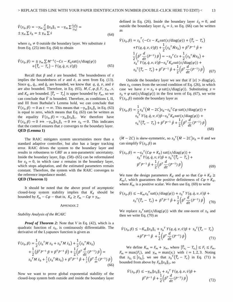
Proof of Theorem 2: Note that V in Eq. (42), which is a
quadratic function of 𝑠∆, is continuously differentiable. The
derivative of the Lyapunov function is given as
�̇�(𝑠∆, 𝑝) =1
2(�̇�∆
𝑇𝑀 𝑠∆ + 𝑠∆𝑇𝑀 �̇�∆) +
1
2(𝑠∆
𝑇�̇�𝑠∆)
+
1
2(�̇�𝑇𝑃−1 𝑝 + 𝑝𝑇𝑃−1 �̇�) +
1
2(𝑝𝑇
𝑑
𝑑𝑡(𝑃−1) 𝑝) =
𝑠∆𝑇𝑀 �̇�∆ +
1
2(𝑠∆
𝑇�̇�𝑠∆) + 𝑝𝑇𝑃−1 �̇� +1
2(𝑝𝑇 𝑑
𝑑𝑡(𝑃−1) 𝑝)
(66)
Now we want to prove global exponential stability of the
closed-loop system both outside and inside the boundary layer
defined in Eq. (26). Inside the boundary layer �̇�∆ = 0, and
outside the boundary layer �̇�∆ = �̇�, so Eq. (66) can be written
as
�̇�(𝑠∆, 𝑝) = 𝑠∆𝑇(−𝐶𝑠 − 𝐾𝑑𝑠𝑎𝑡(𝑠/diag(𝜑)) + (�̂�𝑒 − 𝑇𝑒)
+𝑌(𝑞, �̇�, 𝑣, �̇�)𝑝) +
1
2(𝑠∆
𝑇�̇�𝑠∆) + 𝑝𝑇𝑃−1 �̇� +
1
2(𝑝𝑇
𝑑
𝑑𝑡(𝑃−1) 𝑝) = −𝑠∆
𝑇𝐶𝑠 +1
2(𝑠∆
𝑇�̇�𝑠∆) +
𝑠∆𝑇 𝑌(𝑞, �̇�, 𝑣, �̇�)𝑝−𝑠∆
𝑇𝐾𝑑𝑠𝑎𝑡(𝑠/diag(𝜑)) +
𝑠∆𝑇(�̂�𝑒 − 𝑇𝑒) + 𝑝𝑇𝑃−1 �̇� +
1
2(𝑝𝑇
𝑑
𝑑𝑡(𝑃−1) 𝑝)
(67)
Outside the boundary layer we see that if |𝑠| > diag(𝜑),
then 𝑠∆ comes from the second condition of Eq. (26), in which
case we have 𝑠 = 𝑠∆ + 𝜑 sat(𝑠/diag(𝜑)). Substituting 𝑠 =𝑠∆ + 𝜑 sat(𝑠/diag(𝜑)) in the first term of Eq. (67), we write
�̇�(𝑠∆, 𝑝) outside the boundary layer as
�̇�(𝑠∆, 𝑝) =1
2𝑠∆
𝑇(�̇� − 2𝐶)𝑠∆−𝑠∆𝑇𝐶𝜑 sat(𝑠/diag(𝜑)) +
𝑠∆𝑇 𝑌(𝑞, �̇�, 𝑣, �̇�)𝑝−𝑠∆
𝑇𝐾𝑑𝑠𝑎𝑡(𝑠/diag(𝜑)) +
𝑠∆𝑇(�̂�𝑒 − 𝑇𝑒) + 𝑝𝑇𝑃−1 �̇� +
1
2(𝑝𝑇
𝑑
𝑑𝑡(𝑃−1) 𝑝)
(68)
(�̇� − 2𝐶) is skew-symmetric, so 𝑠∆𝑇(�̇� − 2𝐶)𝑠∆ = 0 and we
can simplify �̇�(𝑠∆, 𝑝) as
�̇�(𝑠∆, 𝑝) = −𝑠∆𝑇(𝐶𝜑 + 𝐾𝑑) sat(𝑠/diag(𝜑)) +
𝑠∆𝑇 𝑌(𝑞, �̇�, 𝑣, �̇�)𝑝 + 𝑠∆
𝑇(�̂�𝑒 − 𝑇𝑒) +
𝑝𝑇𝑃−1 �̇� +
1
2(𝑝𝑇
𝑑
𝑑𝑡(𝑃−1) 𝑝)
(69)
We tune the design parameters 𝐾𝑑 and 𝜑 so that 𝐶𝜑 + 𝐾𝑑 ≥𝐾𝑚𝐼, which guarantees the positive definiteness of 𝐶𝜑 + 𝐾𝑑,
where 𝐾𝑚 is a positive scalar. We then use Eq. (69) to write
�̇�(𝑠∆, 𝑝) ≤ −𝐾𝑚𝑠∆𝑇sat(𝑠/diag(𝜑)) + 𝑠∆
𝑇 𝑌(𝑞, �̇�, 𝑣, �̇�)𝑝 +
𝑠∆𝑇(�̂�𝑒 − 𝑇𝑒) + 𝑝𝑇𝑃−1 �̇� +
1
2(𝑝𝑇
𝑑
𝑑𝑡(𝑃−1) 𝑝)
(70)
We replace 𝑠∆𝑇sat(𝑠/diag(𝜑)) with the one-norm of 𝑠∆ and
then we write Eq. (70) as
�̇�(𝑠∆, 𝑝) ≤ −𝐾𝑚‖𝑠∆‖1 + 𝑠∆𝑇 𝑌(𝑞, �̇�, 𝑣, �̇�)𝑝 + 𝑠∆
𝑇(�̂�𝑒 − 𝑇𝑒)
+𝑝𝑇𝑃−1 �̇� +
1
2(𝑝𝑇
𝑑
𝑑𝑡(𝑃−1) 𝑝)
(71)
We define 𝐾𝑚 = 𝐹𝑚 + 𝛾𝑚, where |�̂�𝑒𝑖− 𝑇𝑒𝑖
| ≤ 𝐹𝑖 ≤ 𝐹𝑚,
𝐹𝑚 = max (𝐹𝑖), and 𝛾𝑚 = max (𝛾𝑖) with 𝑖 = 1, 2, 3. Noting
that 𝑠∆𝑖≤ |𝑠∆𝑖
|, we see that 𝑠∆𝑇(�̂�𝑒 − 𝑇𝑒) in Eq. (71) is
bounded from above by 𝐹𝑚‖𝑠∆‖1, so
�̇�(𝑠∆, 𝑝) ≤ −𝛾𝑚‖𝑠∆‖1 + 𝑠∆𝑇 𝑌(𝑞, �̇�, 𝑣, �̇�)𝑝 +
𝑝𝑇𝑃−1 �̇� +
1
2(𝑝𝑇
𝑑
𝑑𝑡(𝑃−1) 𝑝)
(72)

> REPLACE THIS LINE WITH YOUR PAPER IDENTIFICATION NUMBER (DOUBLE-CLICK HERE TO EDIT) <
14
Since 𝑝 = �̂� − 𝑝, we can substitute Eq. (29) and Eq. (36) into
Eq. (72), and �̇�(𝑠∆, 𝑝) can be written as
�̇�(𝑠∆, 𝑝) ≤ −𝛾𝑚‖𝑠∆‖1 + 𝑠∆𝑇𝑌(𝑞, �̇�, 𝑣, �̇�)𝑝
+
1
2(𝑝𝑇
𝑑
𝑑𝑡(𝑃−1) 𝑝) − 𝑝𝑇 𝑌𝑇(𝑞, �̇�, 𝑣, �̇�)𝑠∆ −
𝑝𝑇𝑊𝑇𝑅𝑊𝑝 = −𝛾𝑚‖𝑠∆‖1 +
1
2(𝑝𝑇
𝑑
𝑑𝑡(𝑃−1) 𝑝)
−𝑝𝑇𝑊𝑇𝑅𝑊𝑝 (73)
By substituting Eq. (37) into Eq. (73), we can write
�̇�(𝑠∆, 𝑝) ≤ −𝛾𝑚‖𝑠∆‖1 −1
2𝑝𝑇𝜗(𝑡)𝑃−1𝑝
− 𝑝𝑇𝑊𝑇(𝑑𝐼 −
1
2𝐼)𝑊𝑝
(74)
𝛾𝑚 > 0, 𝜗(𝑡) ≥ 0, and 𝑃 is positive definite, so by
choosing 𝑑 >1
2, we can see that outside the boundary layer
(that is, the second condition of Eq. (26)), the derivative of the
Lyapunov function is negative semidefinite. This in turn
means that we can use Barbalat’s lemma to prove global
exponential stability. If 𝑉(𝑡, 𝑥) satisfies the Barbalat’s
Lemma conditions, then �̇�(𝑡, 𝑥) → 0 as 𝑡 → ∞, which means
that RCAIC results in a closed-loop system that is globally
exponentially stable.
Now we state an intermediate lemma that we will need to
complete the proof of Theorem 2.
Lemma 2: The derivative of the Lyapunov function of Eq.
(74) globally exponentially converges to zero, which
guarantees convergence to the boundary layer (𝑠∆ → 0). Also,
the prediction error in Eq. (36) of the proposed RCAIC
converges to zero, which implies perfect estimation of the
system parameters.
Proof of Lemma 2: Conditions I and II in Barbalat’s
Lemma are satisfied from Eqs. (42) and (74) and we therefore
conclude that V is bounded, which means that all terms in V
(including 𝑠∆, and 𝑝) are bounded. Since 𝑝 is constant �̂� is
bounded, and since 𝑠∆ is bounded 𝑠 is bounded. From
Eq. (11), since 𝑞𝑑 is bounded, �̇�𝑑, �̈�𝑑, 𝑞𝑟, �̇�𝑟 , and �̈�𝑟 are
bounded. From Eqs. (13)(15), since 𝑠 is bounded, we see
that 𝑒 and �̇� are both bounded. These facts imply that 𝑞, �̇�, �̈�,
𝑣, and �̇� are bounded as well. So 𝑌(𝑞, �̇�, 𝑣, �̇�), 𝑌ʹ(𝑞, �̇�, �̈�), and
𝑊(𝑞, �̇�) are bounded.
By taking the derivative of �̇�(𝑠∆, 𝑝) at its upper bound
we obtain
�̈�(𝑠∆, 𝑝) = ± 𝛾𝑚 ∑�̇�∆ − 𝑝𝑇𝑊𝑇(2𝑑𝐼 − 𝐼)𝑊�̇� −
𝑝𝑇𝑊𝑇(2𝑑𝐼 − 𝐼)�̇�𝑝 − 𝑝𝑇𝜗(𝑡)𝑃−1�̇�
−1
2𝑝𝑇�̇�(𝑡)𝑃−1𝑝 −
1
2𝑝𝑇𝜗(𝑡)
𝑑
𝑑𝑡(𝑃−1)𝑝
(75)
Substituting �̇�, 𝑑
𝑑𝑡(𝑃−1), and �̇� from Eqs. (29), (37), and (25)
respectively into Eq. (75), �̈�(𝑠∆, 𝑝) can be written as follows:
�̈�(𝑠∆, 𝑝) = ± 𝛾𝑚 ∑𝑀−1(−𝐶𝑠 − 𝐾𝑑sat(𝑠/diag(𝜑))
+(�̂�𝑒 − 𝑇𝑒) + 𝑌(𝑞, �̇�, 𝑣, �̇�)𝑝) + 𝑝𝑇𝑊𝑇(2𝑑𝐼 − 𝐼)
𝑊𝑃(t)𝑌𝑇𝑠∆ + 𝑝𝑇𝜗(𝑡)𝑌𝑇𝑠∆ + 𝑝𝑇𝑊𝑇(2𝑑𝐼 − 𝐼) 𝑊𝑃(t)𝑊𝑇(𝑑𝐼)𝑊𝑝 − 𝑝𝑇𝑊𝑇(2𝑑𝐼 − 𝐼)�̇�𝑝 + 𝑝𝑇
𝜗(𝑡)𝑊𝑇(𝑑𝐼)𝑊𝑝 −
1
2𝑝𝑇�̇�(𝑡)𝑃−1𝑝
+
1
2𝑝𝑇𝜗2(𝑡)𝑃−1𝑝 −
1
2𝑝𝑇𝜗(𝑡)𝑊𝑇𝑊𝑝
(76)
Since 𝑃(t) is bounded and its norm is bounded by 𝐾0, then
from Eq. (38), 𝜗(𝑡) and �̇�(𝑡) are bounded. Moreover, since 𝑀,
𝐶, 𝑠, 𝑌, 𝑊, �̇�, 𝑝, and 𝑠∆ are bounded and |�̂�𝑒 − 𝑇𝑒| ≤ 𝐹𝑚, we
see that �̈�(𝑠∆, 𝑝) is bounded. Since we have verified all
conditions in Barbalat’s Lemma, we know that �̇�(𝑠∆, 𝑝) → 0
as 𝑡 → ∞ ⟾𝛾𝑚‖𝑠∆‖1 → 0⟾ 𝑠∆ → 0 as 𝑡 → ∞, which means
that outside the boundary layer, RCIAC guarantees
convergence of 𝑠 to the boundary layer. Furthermore,
�̇�(𝑠∆, 𝑝) → 0 means that 𝑝𝑇𝜗(𝑡)𝑃−1𝑝 → 0 and since
𝑃−1(𝑡) ≥1
𝐾0𝐼, then if 𝑊 is PE, 𝜗(𝑡) > 𝜗 > 0, so we have
𝜗(𝑡)𝑝𝑇𝑃−1𝑝 ≥ 𝜗𝑝𝑇𝑝/𝐾0 (77)
Therefore, 𝑝𝑇𝜗(𝑡)𝑃−1𝑝 → 0 means that 𝑝 → 0. To achieve
faster exponential convergence of 𝑠 to the boundary layer and
convergence of the prediction error to zero, we define a
strictly positive constant Ч0, where Ч0 = min (2𝜗0, 𝜗), and we
write [48]:
�̇�(𝑡) + Ч0𝑉(𝑡) ≤ 0 , 𝑉(𝑡) ≤ 𝑉(0)𝑒−Ч0𝑡 (78)
On the other hand, inside the boundary layer, where |𝑠| ≤diag(𝜑), Eqs. (68)(78) can be rewritten for 𝑠∆ = 0. For this
condition, 𝑠 remains inside the boundary layer and the
prediction error exponentially converges to zero. Outside the
boundary layer, both 𝑠∆ and 𝑒𝑝 exponentially converge to zero,
which means that we achieve perfect parameter estimation and
guarantee convergence of th 𝑠 to the boundary layer.
QED (Lemma 2)
We see from the above that the closed-loop system with
the proposed RCAIC converges to the target impedance
model. Therefore, the controller drives the system to the
boundary layer, achieves perfect parameter estimation, and
achieves robustness against GRFs.
QED (Theorem 2)
Note that the exponential stability proof implies that 𝐾𝑑
must be bounded from below by 𝐹𝑚 − 𝐶𝜑 (that is,𝐾𝑑 ≥ 𝐹𝑚 −𝐶𝜑 + 𝛾𝑚).
ACKNOWLEDGMENT
This research is supported by NSF Grant 1344954. The
authors are grateful to Jean-Jacques Slotine, Mojtaba Sharifi,
Antonie van den Bogert, and Thang Tien Nguyen for
suggestions that improved this paper.

> REPLACE THIS LINE WITH YOUR PAPER IDENTIFICATION NUMBER (DOUBLE-CLICK HERE TO EDIT) <
15
REFERENCES
[1] K. Ziegler-Graham, “Estimating the prevalence of limb loss in the
United States: 2005 to 2050,” Archives of Physical Medicine and
Rehabilitation, vol. 89, no. 3, pp. 422–429, 2008. [2] J. M. Robbins et al., “Mortality rates and diabetic foot ulcers,”
Journal of the American Podiatric Medical Association, vol. 98, no.
6, pp. 489–493, 2008. [3] F. Sup, H. A. Varol, M. Goldfarb, “Upslope walking with a powered
knee and ankle prosthesis: initial results with an amputee subject,”
IEEE Transactions on Neural Systems and Rehabilitation
Engineering, vol. 19, no. 1, pp. 71–78, 2010. [4] B. E. Lawson, H. A. Varol, M. Goldfarb, “Standing stability
enhancement with an intelligent powered transfemoral
prosthesis,” IEEE Transactions on Biomedical Engineering, vol. 58, no. 9, pp. 2617–2624, 2011.
[5] C. D. Hoover, G. D. Fulk, K. B. Fite, “Stair ascent with a powered
transfemoral prosthesis under direct myoelectric control,” IEEE/ASME Transactions on Mechatronics, vol. 18, no. 3, pp. 1191–1200, 2013.
[6] F. Sup, H. A. Varol, J. Mitchell, T. J. Withrow, M. Goldfarb,
“Preliminary evaluations of a self-contained anthropomorphic transfemoral prosthesis,” IEEE/ASME Transactions on Mechatronics,
vol. 14, no. 6, pp. 667–676, 2009. [7] K. Fite, J. Mitchell, F. Sup, M. Goldfarb, “Design and control of an
electrically powered knee prosthesis,” IEEE 10th International
Conference on Rehabilitation Robotics, Noordwijk, Netherlands, 2007.
[8] D. Popovic, M. N. Oguztoreli, R. B. Stein, “Optimal control for the
active above-knee prosthesis,” Annals of Biomedical Engineering, vol. 19, no. 2, pp. 131–150, 1991a.
[9] D. Popovic, R. Tomovic, D. Tepavac, L. Schwirtlich, “Control aspects
of active above-knee prosthesis”, International Journal of Man-Machine Studies, vol. 35, no.6, pp. 751–767, 1991b.
[10] F. Sup, A. Bohara, M. Goldfarb, “Design and control of a powered
transfemoral prosthesis”, International Journal of Robotics Research, vol. 27, no. 2, pp. 263–273, 2008.
[11] G. Khademi, H. Mohammadi, E. C. Hardin, D. Simon, “Evolutionary
optimization of user intent recognition for transfemoral amputees,” Biomedical Circuits and Systems Conference, Atlanta, GA, 2015.
[12] S. A. Fakoorian, D. Simon, H. Richter and V. Azimi, “Ground reaction
force estimation in prosthetic legs with an extended Kalman filter,”
IEEE International Systems Conference, Orlando, FL, 2016. [13] R. D. Gregg, J. W. Sensinger, “Towards biomimetic virtual constraint
control of a powered prosthetic leg,” IEEE Transactions on Control Systems Technology, vol. 22, no. 1, pp. 246–254, 2014.
[14] H. Richter, D. Simon, A. van den Bogert, “Semiactive virtual control
method for robots with regenerative energy-storing joints,” 19th International Federation of Automatic Control World Congress, Cape
Town, South Africa, 2014a. [15] H. Richter, D. Simon, W. Smith, S. Samorezov, “Dynamic modeling,
parameter estimation and control of a leg prosthesis test robot,”
Applied Mathematical Modelling, vol. 39, no. 12, pp. 559–573, 2015. [16] V. Azimi, D. Simon, H. Richter, “Stable robust adaptive impedance
control of a prosthetic leg,” ASME Dynamic Systems and Control
Conference, Columbus, OH, 2015. [17] V. Azimi, D. Simon, H. Richter, S. Fakoorian, “Robust composite
adaptive transfemoral prosthesis control with non-scalar boundary
layer trajectories,” American Control Conference, Boston, MA, 2016. [18] H. Warner, D. Simon, H. Mohammadi, H. Richter, “Switched robust
tracking/impedance control for an active transfemoral prosthesis,”
American Control Conference, Boston, MA, 2016. [19] P. Khalaf, H. Richter, A. van den Bogert, D. Simon, “Multi-objective
optimization of impedance parameters in a prosthesis test robot,”
ASME Dynamic Systems and Control Conference, Columbus, OH,
2015. [20] D. Ebeigbe, D. Simon, and H. Richter, “Hybrid Function
Approximation Based Control with Application to Prosthetic
Legs,” IEEE International Systems Conference, Orlando, FL, 2016. [21] H. Zhao, J. Reher, J. Horn, V. Paredes, A. D. Ames, “Realization of
nonlinear real-time optimization based controllers on self-contained
transfemoral prosthesis,” IEEE/ACM International Conference on Cyber-Physical Systems, Seattle, WA, 2015.
[22] H. Zhao, A. D. Ames, “Quadratic program based control of fully-
actuated transfemoral prosthesis for flat-ground and up-slope
locomotion,” American Control Conference, Portland, OR 2014a. [23] H. Zhao, S. Kolathaya, A. D. Ames, “Quadratic programming and
impedance control for transfemoral prosthesis,” IEEE International
Conference on Robotics and Automation, Hong Kong, China, 2014b. [24] H. Zhao , J. Horn, J. Reher, V. Paredes, A. D. Ames, “First steps
toward translating robotic walking to prostheses: a nonlinear
optimization based control approach,” Autonomous Robots, pp.1–18,
2016a. [25] H. Zhao, J. Horn, J. Reher, V. Paredes, A. D. Ames, “Multicontact
Locomotion on Transfemoral Prostheses via Hybrid System Models
and Optimization-Based Control,” IEEE Transactions on Automation Science and Engineering, vol. 13, no. 2, pp. 502–513, 2016b.
[26] C. Ott, R. Mukherjee, Y. Nakamura, “Unified impedance and
admittance control,” IEEE International Conference on Robotics and Automation, Anchorage, AK, 2010.
[27] A. Abdossalami, S. Sirouspour, “Adaptive control for improved
transparency in haptic simulations,” IEEE Transactions on Haptics, vol. 2, no. 1, pp. 2–14, 2009.
[28] N. Hogan, “Impedance control: An approach to manipulation: Part I,
Part II and Part III,” ASME J. Dynamic Systems, Measurement and Control, vol. 107, no.1, pp. 1–24, 1985.
[29] S. P. Chan, B. Yao, W. B. Gao, M. Cheng, “Robust impedance control
of robot manipulators,” International J. of Robotics and Automation,
vol. 6, no. 4, pp. 220–227, 1991. [30] J.-J. E. Slotine, J. A. Coetsee, “Adaptive sliding controller synthesis
for non-linear systems,” International Journal of Control, vol. 43, no. 6, pp. 1631–1651, 1986.
[31] S. Hussain, S. Q. Xie, P.K. Jamwal, “Adaptive impedance control of a robotic orthosis for gait rehabilitation,” IEEE Transactions on
Cybernetics, vol. 43 , no. 3, pp. 1025-1034, 2013. [32] M. Sharifi, S. Behzadipour, G. Vossoughi, “Nonlinear model reference
adaptive impedance control for human–robot interactions,” Control
Engineering Practice, vol. 32, no. 8, pp. 9–27, 2014. [33] H. Park, J. Lee, “Adaptive impedance control of a haptic interface,”
Mechatronics, vol. 14, no. 3, pp. 237–253, 2004. [34] L. Zhijun, S. S. Ge, “Adaptive robust controls of biped robots,”
Control Theory & Applications, IET, vol. 7, no. 2, pp. 161–175, 2013. [35] P. Tomei, “Robust adaptive friction compensation for tracking control
of robot manipulators,” IEEE Transactions on Automatic
Control, vol. 45, no. 11, pp. 2164–2169, 2000. [36] S.-H. Huh, Z. Bien, “Robust sliding mode control of
a robot manipulator based on variable structure-model
reference adaptive control approach,” IET Control Theory & Applications, vol. 1, no. 5, pp. 1355–1363, 2007.
[37] V. Azimi, M. B. Menhaj, A. Fakharian, “Tool position tracking control
of a nonlinear uncertain flexible robot manipulator by using robust H2/H∞ controller via T-S fuzzy model,” Sadhana, vol. 40, no. 2, pp.
307-333, 2015. [38] V. Azimi, M. B. Menhaj, A. Fakharian, “Position and current control
of a Permanent-Magnet Synchronous Motor by using loop-shaping
methodology: blending of H∞ mixed-sensitivity problem and T-S
fuzzy model scheme,” Journal of Dynamic Systems, Measurement and Control - Transactions of the ASME, vol.135, no. 5, pp. 051006-1–
051006-11, 2013. [39] V. Azimi, M. A. Nekoui, A. Fakharian, “Robust multi-objective H2/
H∞ tracking control based on T-S fuzzy model for a class of nonlinear
uncertain drive systems,” Proceedings of the Institution of Mech. Eng.
Part I - Journal of Systems and Control Engineering, vol. 226, no. 8, pp. 1107–1118, 2012.
[40] J.-J. E. Slotine, W. Li, “Adaptive strategy in constrained
manipulators,” IEEE International Conference on Robotics and
Automation, Raleigh, NC, 1987. [41] J.-J. E. Slotine, W. Li, “Adaptive manipulator control: a study case,”
IEEE Transactions on Automatic Control, vol. 33, no. 11, pp. 995–1003, 1988.
[42] J.-J. E. Slotine, J. A. Coetsee, “Composite adaptive controller of robot
manipulators,” Automatica, vol. 25, no. 4, pp. 509–519, 1989. [43] J. Yuan, Y. Stepanenko, “Composite adaptive controller of flexible
joint robots,” Automatica, vol. 29, no. 3, pp. 609–619, 1993. [44] R. M. Sanner, J.-J. E. Slotine, “Gaussian networks for direct adaptive
control,” IEEE Transactions on Neural Networks, vol. 3 , no. 6 , pp. 837-863, 1992.
[45] H. Richter, D. Simon, “Robust tracking control of a prosthesis test
robot,” Journal of Dynamic Systems, Measurement, and Control, vol. 136, no. 3, 2014b.

> REPLACE THIS LINE WITH YOUR PAPER IDENTIFICATION NUMBER (DOUBLE-CLICK HERE TO EDIT) <
16
[46] M. Ackermann, A. J. van den Bogert, “Optimality principles for
model-based prediction of human gait,” Journal of Biomechanics, vol. 43, no. 6, pp. 1055–1060, 2010.
[47] A.-C. Huang, M.-C. Chien, Adaptive control of robot manipulators,
World Scientific Publishing, 2010. [48] J.-J. E. Slotine, W. Li, Applied nonlinear control, NJ: Prentice-Hall,
1991. [49] D. A. Winter, “Kinematic and kinetic patterns in human gait:
variability and compensating effects,” Human Movement Science, vol.
3, no. 1–2, pp. 51–76, 1984. [50] D. A. Winter, Biomechanics and motor control of human movement,
John Wiley & Sons, 2009. [51] A. J. van den Bogert, T. Geijtenbeek, O. Even Zohar, F. Steenbrink, E.
C. Hardin, “A real-time system for biomechanical analysis of human movement and muscle function,” Medical & Biological Engineering &
Computing, vol. 51, no. 10, pp. 1069–1077, 2013.


![Jestr EngineeringScience!and! · Proof. We prove this result via backstepping control method and Lyapunov stability theory. Using ... Thus, using Barbalat’s lemma [125], we can](https://img.pdfslide.net/doc/110x75/5ad3733b7f8b9abd6c8df4a2/jestr-engineeringscienceand-we-prove-this-result-via-backstepping-control-method.jpg)