Embed Size (px)
Citation preview
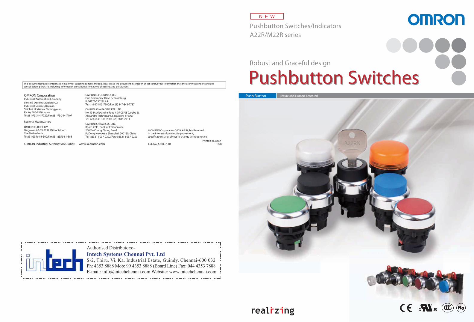
Robust and Graceful design
Pushbutton SwitchesPushbutton SwitchesPush Button Secure and Human-centered
Pushbutton Switches/IndicatorsA22R/M22R series
This document provides information mainly for selecting suitable models. Please read the document Instruction Sheet carefully for information that the user must understand and accept before purchase, including information on warranty, limitations of liability, and precautions.
In the interest of product improvement, specifications are subject to change without notice.
Cat. No. A190-E1-01OMRON Industrial Automation Global: www.ia.omron.comPrinted in Japan
1009
OMRON CorporationIndustrial Automation Company
Regional Headquarters
OMRON EUROPE B.V.Wegalaan 67-69-2132 JD HoofddorpThe NetherlandsTel: (31)2356-81-300/Fax: (31)2356-81-388
OMRON ELECTRONICS LLCOne Commerce Drive Schaumburg,IL 60173-5302 U.S.A.Tel: (1) 847-843-7900/Fax: (1) 847-843-7787
OMRON ASIA PACIFIC PTE. LTD.No. 438A Alexandra Road # 05-05/08 (Lobby 2), Alexandra Technopark, Singapore 119967Tel: (65) 6835-3011/Fax: (65) 6835-2711
OMRON (CHINA) CO., LTD.Room 2211, Bank of China Tower, 200 Yin Cheng Zhong Road, PuDong New Area, Shanghai, 200120, ChinaTel: (86) 21-5037-2222/Fax: (86) 21-5037-2200
Sensing Devices Division H.Q.Industrial Sensors DivisionShiokoji Horikawa, Shimogyo-ku,Kyoto, 600-8530 JapanTel: (81)75-344-7022/Fax: (81)75-344-7107
© OMRON Corporation 2009 All Rights Reserved.
Authorised Distributors:-
Intech Systems Chennai Pvt. LtdS-2, Thiru. Vi. Ka. Industrial Estate, Guindy, Chennai-600 032
Ph: 4353 8888 Mob: 99 4353 8888 (Board Line) Fax: 044 4353 7888
E-mail: [email protected] Website: www.intechchennai.com
2 3
1
2
3
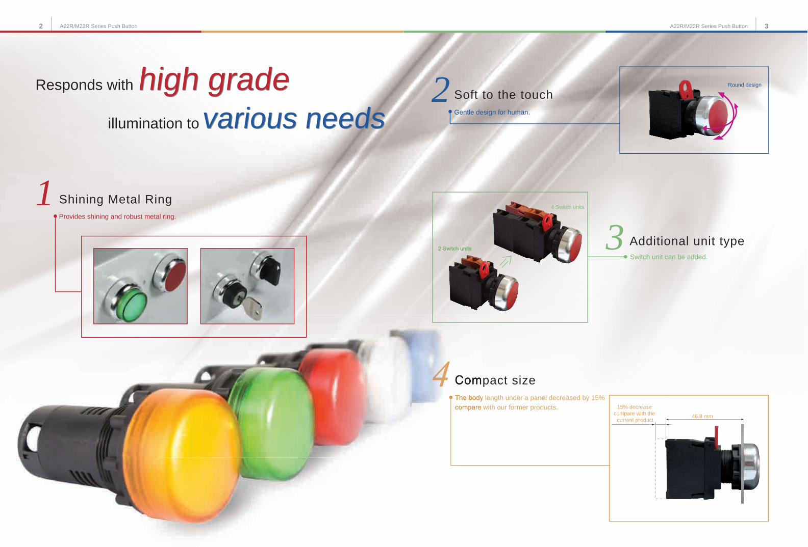
4 Compact sizeThe body length under a panel decreased by 15% compare with our former products.
Additional unit typeSwitch unit can be added.
Responds with
Shining Metal Ring
Soft to the touch
Provides shining and robust metal ring.
Gentle design for human.
2 Switch units
4 Switch units
46.8 mm
15% decrease compare with the
current product
Round design
illumination to
high gradehigh gradevarious needsvarious needs
A22R/M22R Series Push Button A22R/M22R Series Push Button
4 5A22R/M22R Series Push Button A22R/M22R Series Push Button
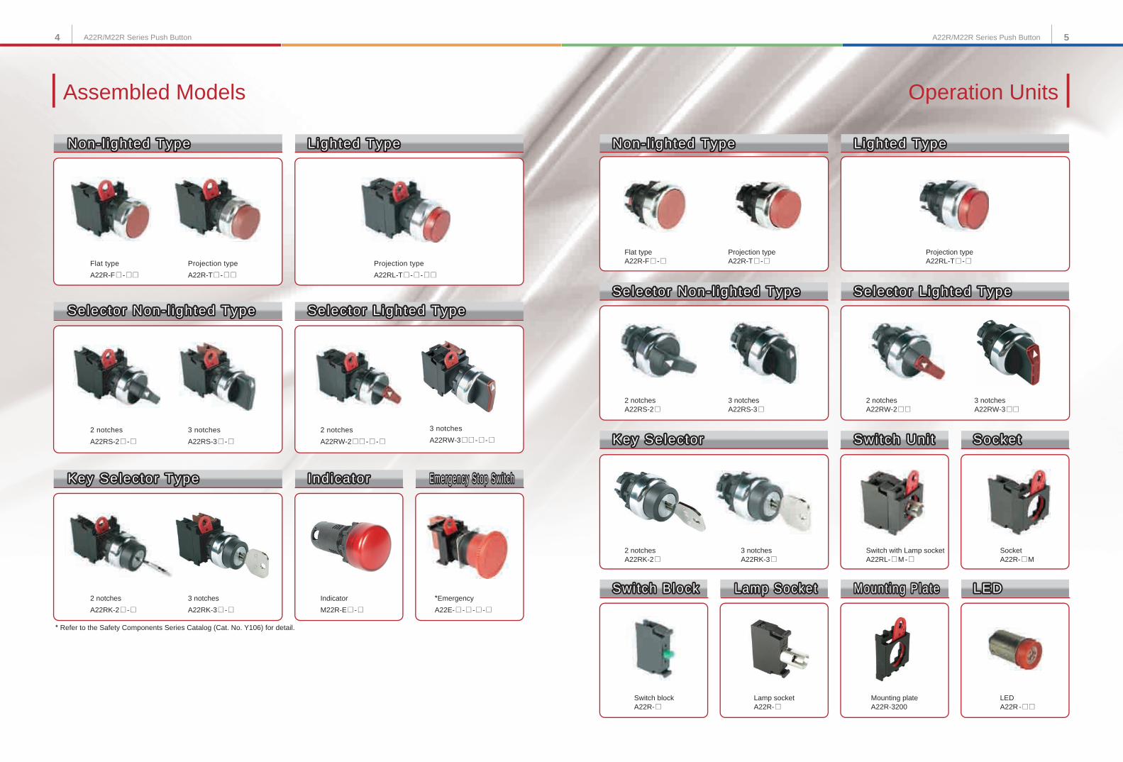
* Refer to the Safety Components Series Catalog (Cat. No. Y106) for detail.
Operation UnitsAssembled Models
3 notches
A22RW-3 @ @ - @ - @2 notches
A22RS-2 @ - @2 notches
A22RW-2 @ @ - @ - @3 notches
A22RS-3 @ - @
*Emergency
A22E- @ - @ - @ - @2 notches
A22RK-2 @ - @3 notches
A22RK-3 @ - @Indicator
M22R-E @ - @
Flat typeA22R-F @ - @
Projection type A22RL-T @ - @
Projection typeA22R-T @ - @
2 notchesA22RS-2 @
2 notchesA22RW-2 @ @
3 notchesA22RS-3 @
3 notchesA22RW-3 @ @
2 notchesA22RK-2 @
3 notchesA22RK-3 @
Switch with Lamp socketA22RL- @ M - @
SocketA22R- @ M
Switch blockA22R- @
Lamp socketA22R- @
Mounting plateA22R-3200
LEDA22R - @ @
Projection type
A22RL-T @ - @ - @ @Flat type
A22R-F @ - @ @Projection type
Lighted Type
Non-l ighted TypeNon-l ighted Type
A22R-T @ - @ @
Lighted TypeLighted Type Non-l ighted TypeNon-l ighted Type Lighted TypeLighted Type
Selector Non- l ighted TypeSelector Non- l ighted Type Selector Lighted TypeSelector Lighted Type
Key SelectorKey Selector Switch Uni tSwitch Uni t SocketSocket
Switch BlockSwitch Block Lamp SocketLamp Socket Mount ing PlateMount ing Plate LEDLED
Selector Non- l ighted TypeSelector Non- l ighted Type Selector Lighted TypeSelector Lighted Type
Key Selector TypeKey Selector Type IndicatorIndicator Emergency Stop SwitchEmergency Stop Switch
Non- l ighted Type
Selector Non- l ighted Type Selector Lighted Type
Key Selector Type Indicator Emergency Stop Switch
L ighted Type Non-l ighted Type Lighted Type
Selector Non- l ighted Type Selector Lighted Type
Key Selector Switch Uni t Socket
Switch Block Lamp Socket Mount ing Plate LED
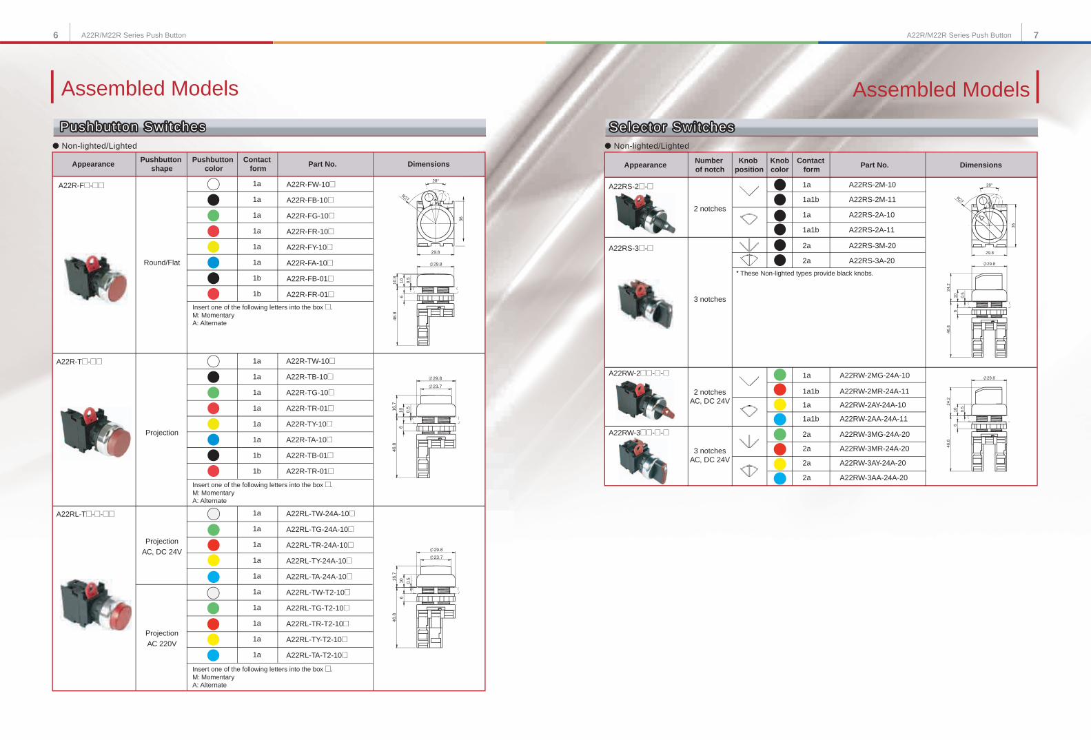
Assembled Models
A22RS-2@-@
● Non-lighted/Lighted
2 notches
1a
2a
2a
1a1b
1a
1a1b
A22RS-2M-10
A22RS-3A-20
A22RS-3M-20
A22RS-2A-11
A22RS-2A-10
A22RS-2M-11
3 notches
A22RS-3@-@
1a
2a
2a
2a
1a1b
1a
1a1b
2a
2 notchesAC, DC 24V
A22RW-2MG-24A-10
A22RW-2AA-24A-11
A22RW-2AY-24A-10
A22RW-2MR-24A-11
3 notchesAC, DC 24V A22RW-3AY-24A-20
A22RW-3MR-24A-20
A22RW-3AA-24A-20
A22RW-3MG-24A-20
29.8
36
28°
R27
0.5
29.8
6
24.2
10
46.8
0.5
29.8
6
24.2
10
46.8
● Non-lighted/Lighted
1a
1a
1a
1a
1a
1a
1a
1a
1a
1a
A22RL-TW-24A-10@
A22RL-TG-24A-10@
A22RL-TR-24A-10@
A22RL-TY-24A-10@
A22RL-TA-24A-10@
A22RL-TW-T2-10@
A22RL-TG-T2-10@
A22RL-TR-T2-10@
A22RL-TY-T2-10@
A22RL-TA-T2-10@
1a
1a
1a
1a
1a
1a
1b
1b
1a
1a
1a
1a
1a
1a
1b
1b
A22R-TW-10@
A22R-TB-10@
A22R-TG-10@
A22R-TR-01@
A22R-TY-10@
A22R-TA-10@
A22R-TB-01@
A22R-TR-01@
Insert one of the following letters into the box @.M: Momentary A: Alternate
Insert one of the following letters into the box @.M: Momentary A: Alternate
23.7
29.8
0.5
46.8
61016
. 7
23.7
29.8
0.5
46.8
61016
.7
Projection
ProjectionAC, DC 24V
ProjectionAC 220V
Round/Flat
Dimensions
A22R-FW-10@
A22R-FB-10@
A22R-FG-10@
A22R-FR-10@
A22R-FY-10@
A22R-FA-10@
A22R-FB-01@
A22R-FR-01@
Insert one of the following letters into the box @.M: Momentary A: Alternate
36
29.8
R27
28°
29.8
46.8
6
10.8
0.5
10
A22RL-T@-@-@@
A22R-T@-@@
A22R-F@-@@
Number of notch
Appearance
* These Non-lighted types provide black knobs.
6 7A22R/M22R Series Push ButtonA22R/M22R Series Push Button
Selector SwitchesSelector Switches
A22RW-2@@-@-@
A22RW-3@@-@-@
Pushbutton SwitchesPushbutton SwitchesPushbutton Switches
Pushbutton shape
Pushbutton color
Contact form
Part No. DimensionsContact
formPart No.Appearance
Assembled Models
Selector Switches
Knobcolor
Knob position
StructureAssembled Models
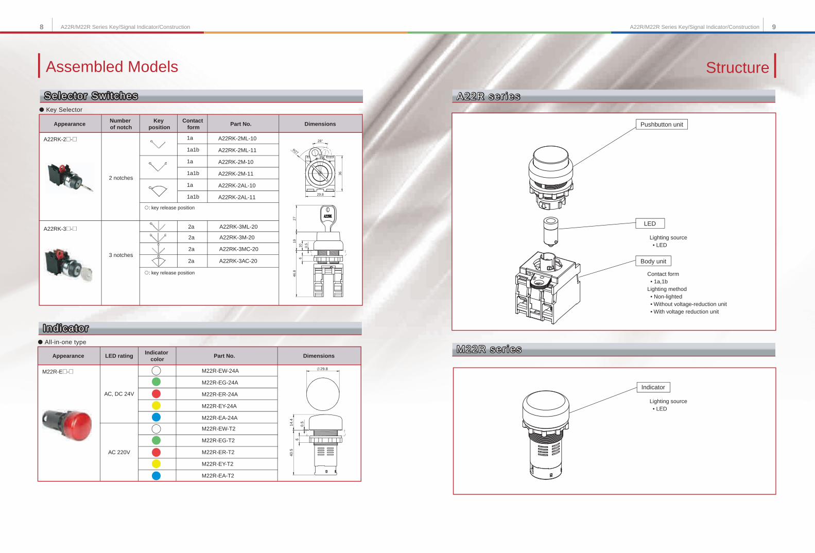
8 9A22R/M22R Series Key/Signal Indicator/ConstructionA22R/M22R Series Key/Signal Indicator/Construction
A22RK-3@-@
● Key Selector
1a
1a1b
1a
1a1b
1a
1a1b
2a
2a
2a
2a
A22RK-2@-@
2 notches
3 notches
A22RK-2ML-10
A22RK-2ML-11
A22RK-2M-10
A22RK-2M-11
A22RK-2AL-10
A22RK-2AL-11
A22RK-3ML-20
A22RK-3M-20
A22RK-3MC-20
A22RK-3AC-20
: key release position
: key release position
Selector SwitchesSelector SwitchesSelector Switches
29.8
36
28°
R27
27
0.5
46.8
6
19
1 0
● All-in-one type
M22R-E@-@
AC, DC 24V
AC 220V
M22R-EW-24A
M22R-EG-24A
M22R-ER-24A
M22R-EY-24A
M22R-EA-24A
M22R-EW-T2
M22R-EG-T2
M22R-ER-T2
M22R-EY-T2
M22R-EA-T2
IndicatorIndicatorIndicator
29.8
0.5
40.5
6
14.4
Lighting source • LED
Contact form • 1a,1bLighting method • Non-lighted • Without voltage-reduction unit • With voltage reduction unit
Pushbutton unit
LED
Body unit
Lighting source • LED
Indicator
A22R ser iesA22R ser iesA22R ser ies
M22R ser iesM22R ser iesM22R ser ies
Number of notch
Appearance DimensionsContact
formPart No.
Key position
LED ratingAppearance DimensionsPart No.Indicator
color
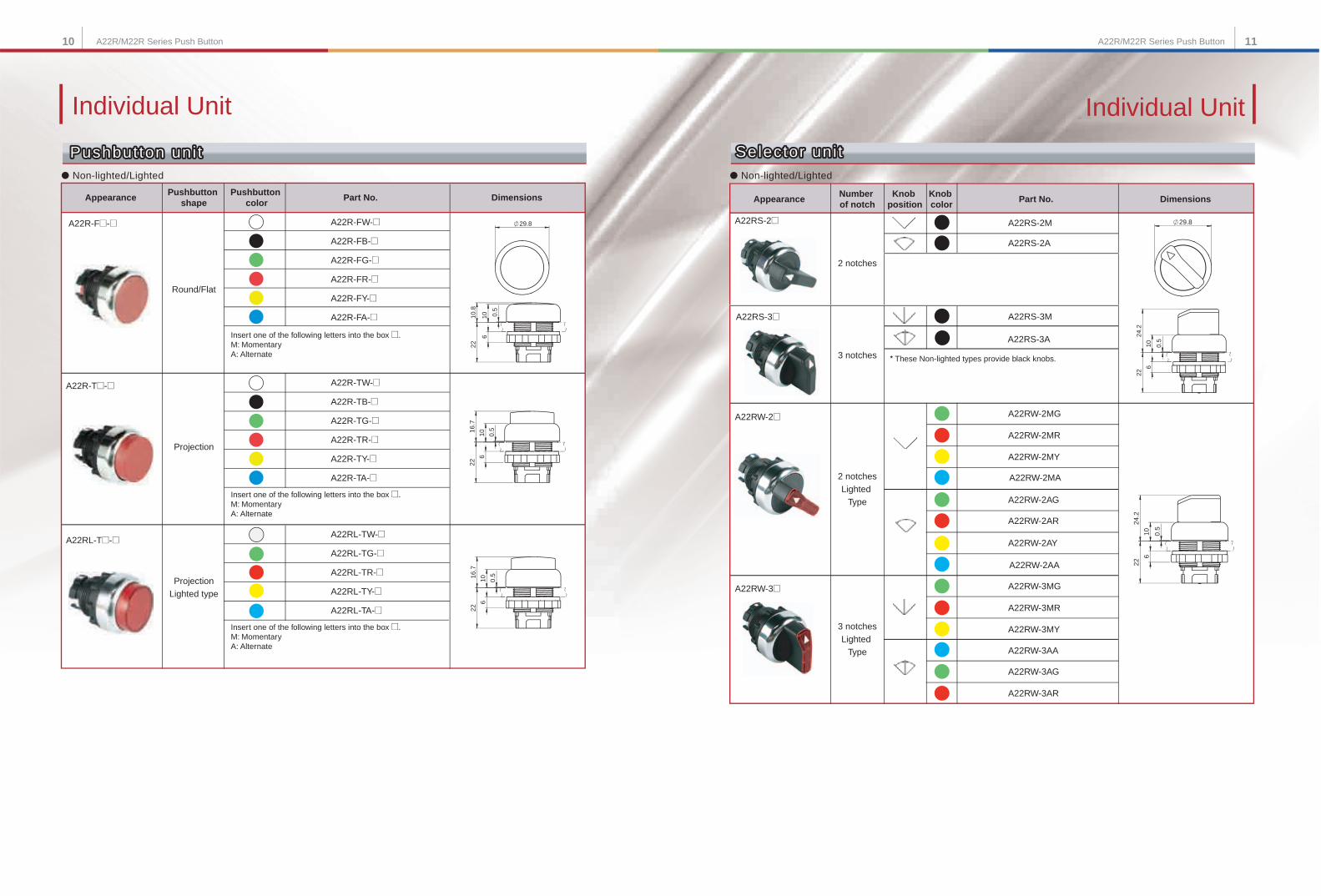
Individual UnitIndividual Unit
A22RS-2@
● Non-lighted/Lighted
2 notches
3 notches
A22RS-2M
A22RS-3A
A22RS-3M
A22RS-2A
A22RS-3@
A22RW-2@
2 notchesLighted
Type
3 notchesLighted
Type
A22RW-3@
A22RL-T@-@
A22R-T@-@
● Non-lighted/Lighted
Projection
ProjectionLighted type
A22RL-TW-@
A22RL-TG-@
A22RL-TR-@
A22RL-TY-@
A22RL-TA-@
A22R-TW-@
A22R-TB-@
A22R-TG-@
A22R-TR-@
A22R-TY-@
A22R-TA-@
Insert one of the following letters into the box @.M: Momentary A: Alternate
Insert one of the following letters into the box @.M: Momentary A: Alternate
A22R-F@-@ A22R-FW-@
A22R-FB-@
A22R-FG-@
A22R-FR-@
A22R-FY-@
A22R-FA-@
Insert one of the following letters into the box @.M: Momentary A: Alternate
A22RW-2MG
A22RW-2MA
A22RW-2MY
A22RW-2MR
A22RW-3MG
A22RW-3MY
A22RW-3MR
A22RW-3AG
A22RW-3AR
A22RW-2AG
A22RW-2AA
A22RW-2AY
A22RW-2AR
A22RW-3AA
* These Non-lighted types provide black knobs.
10 11A22R/M22R Series Push ButtonA22R/M22R Series Push Button
Pushbutton uni tPushbutton uni t
29.8
0.5
610
2210
.8
0.5
6
22
1016.7
0.5
6
22
1016.7
Selector uni tSelector uni t
0.5
22
6
24.2
1 0
29.8
0.5
22
6
24.2
1 0
Pushbutton uni t
DimensionsPart No.AppearancePushbutton
shapePushbutton
color
Round/Flat
Number of notch
Appearance DimensionsPart No.Knob color
Knob position
Selector uni t
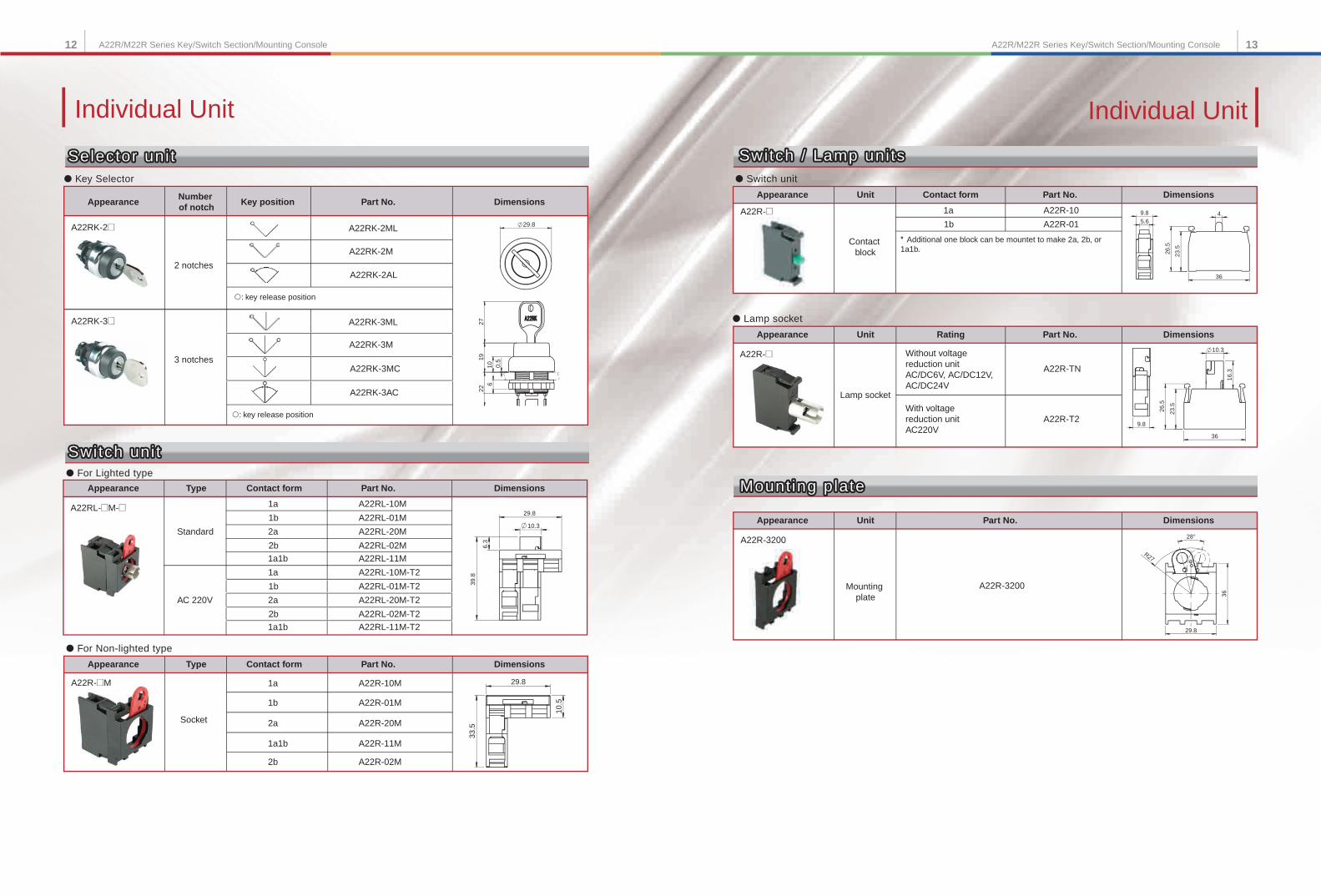
Individual Unit
A22RK-3@
● Key Selector
A22RK-2@
2 notches
3 notches
A22RK-2ML
A22RK-2M
A22RK-2AL
A22RK-3ML
A22RK-3M
A22RK-3MC
A22RK-3AC
�: key release position
�: key release position
12 13A22R/M22R Series Key/Switch Section/Mounting ConsoleA22R/M22R Series Key/Switch Section/Mounting Console
27
0.5
226
1910
29.8
● For Lighted type
● For Non-lighted type
1a
1a1b
A22RL-@M-@
Standard
AC 220V
A22RL-10M
1b A22RL-01M
2a A22RL-20M
2b A22RL-02M
A22RL-11M
1a
1a1b
A22RL-10M-T2
1b A22RL-01M-T2
2a A22RL-20M-T2
2b A22RL-02M-T2
A22RL-11M-T2
10.3
29.8
6.3
39.8
1a
1a1b
Socket
A22R-10M
1b A22R-01M
2a A22R-20M
2b A22R-02M
A22R-11M
● Switch unit
● Lamp socket
Without voltage reduction unitAC/DC6V, AC/DC12V,AC/DC24V
Lamp socket
A22R-TN
A22R-T2
A22R-@
With voltage reduction unit AC220V
10.5
33.5
29.8A22R-@M
1a
Contact block
A22R-10
1b A22R-01
* Additional one block can be mountet to make 2a, 2b, or 1a1b.
5.69.8
36
4
26.5
23.5
A22R-@
36
26.5
23.5
16.3
10.3
9.8
A22R-3200
A22R-3200
Mount ing plateMount ing plate
Mounting plate
29.8
36
28°
R27
Individual Unit
Selector uni tSelector uni tSelector uni t
Number of notch
Appearance DimensionsPart No.Key position
TypeAppearance DimensionsPart No.Contact form
TypeAppearance DimensionsPart No.Contact form
Switch uni tSwitch uni tSwitch uni t
UnitAppearance DimensionsPart No.Contact form
UnitAppearance DimensionsPart No.Rating
UnitAppearance DimensionsPart No.
Switch / Lamp uni tsSwitch / Lamp uni tsSwitch / Lamp uni ts
Mount ing plate
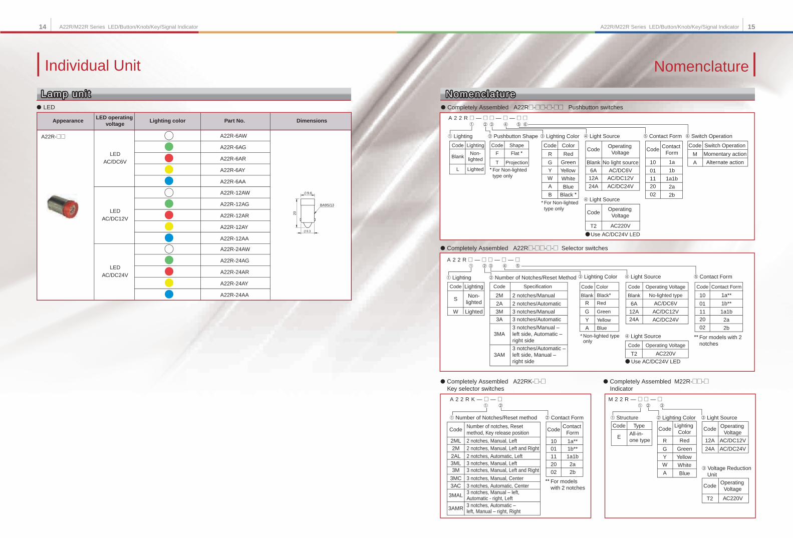
Individual Unit
14 15A22R/M22R Series LED/Button/Knob/Key/Signal IndicatorA22R/M22R Series LED/Button/Knob/Key/Signal Indicator
● Completely Assembled A22R@-@@-@-@@ Pushbutton switches
● Completely Assembled A22R@-@@-@-@ Selector switches
● Completely Assembled A22RK-@-@ Key selector switches
A 2 2 R @ — @ @ — @ — @ @
Non-lighted
Lighting
Lighted
Code
Blank
L
➁➀
➁➀
➀ Lighting
* For Non-lighted type only
Flat *Shape
Projection
Code
F
T
➁ Pushbutton Shape
➄➃➂
➄➃➂
➅
➃ Light Source
Use AC/DC24V LED
Operating Voltage
AC/DC6V
No light sourceBlank
Code
12A6A
AC/DC12V
24A AC/DC24V
Switch Operation
Alternate action
Momentary actionM
Code
A
Operating Voltage
AC220VT2
Code
* For Non-lighted type only
* Non-lighted type only
Color
Green
RedR
Code
Y
G
Yellow
B
A
W
Black *Blue
White
➂ Lighting Color ➃ Light Source ➄ Contact Form ➅ Switch Operation
Contact Form
Code
1b
1a10
11
01
1a1b
02
20
2b
2a
A 2 2 R @ — @ @ — @ — @
➃ Light Source
Use AC/DC24V LED
Operating Voltage
AC220VT2
Code
➃ Light Source ➄ Contact Form
** For models with 2 notches
Contact Form
1b**
1a**10
Code
11
01
1a1b
02
20
2b
2a
Non-lighted
Lighting
Lighted
Code
S
W
Color
Black*Blank
Code
Red
G
R
Green
A
Y
Blue
Yellow
➀ Lighting ➁ Number of Notches/Reset Method ➂ Lighting Color
Specification
2 notches/Automatic
2 notches/Manual2M
Code
3M
2A
3 notches/Manual3 notches/Automatic3A
3MA
3AM
3 notches/Manual – left side, Automatic – right side
3 notches/Automatic – left side, Manual – right side
Operating Voltage
AC/DC6V
No-lighted typeBlank
Code
12A
6A
AC/DC12V24A AC/DC24V
➁➀
➀ Number of Notches/Reset method
A 2 2 R K — @ — @
Number of notches, Reset method, Key release position
2 notches, Manual, Left2ML
Code
2 notches, Manual, Left and Right2M
2AL 2 notches, Automatic, Left3 notches, Manual, Left3ML3 notches, Manual, Left and Right3M
3 notches, Manual, Center3MC3 notches, Automatic, Center3AC
3MAL 3 notches, Manual – left, Automatic - right, Left
3AMR 3 notches, Automatic – left, Manual – right, Right
➁ Contact Form
** For models with 2 notches
Contact Form
1b**1a**10
Code
1101
1a1b
02
20
2b
2a
● Completely Assembled M22R-@@-@ Indicator
➂ Voltage Reduction Unit
Operating Voltage
AC220VT2
Code
➂ Light Source
Operating Voltage
Code
12A AC/DC12V
24A AC/DC24V
➁ Lighting Color
M 2 2 R — @ @ — @➁➀
➀ Structure
All-in-one type
TypeCode
E
Green
RedR
Code
Y
G
Yellow
A
W
Blue
White
➂
● LED
Lamp uni tLamp uni t
A22R-@@
LEDAC/DC6V
LEDAC/DC12V
LEDAC/DC24V
A22R-6AW
A22R-6AG
A22R-6AR
A22R-6AY
A22R-6AA
A22R-12AW
A22R-12AG
A22R-12AR
A22R-12AY
A22R-12AA
A22R-24AW
A22R-24AG
A22R-24AR
A22R-24AY
A22R-24AA20
9.6
9.3
BA9S/13
Lamp uni t
DimensionsLED operating
voltageLighting color Part No.Appearance
NomenclatureNomenclature
Nomenclature
Nomenclature
Lighting Color
16 17A22R/M22R Series Switch Section/ Indicator Section/LEDA22R/M22R Series Switch Section/ Indicator Section/LED
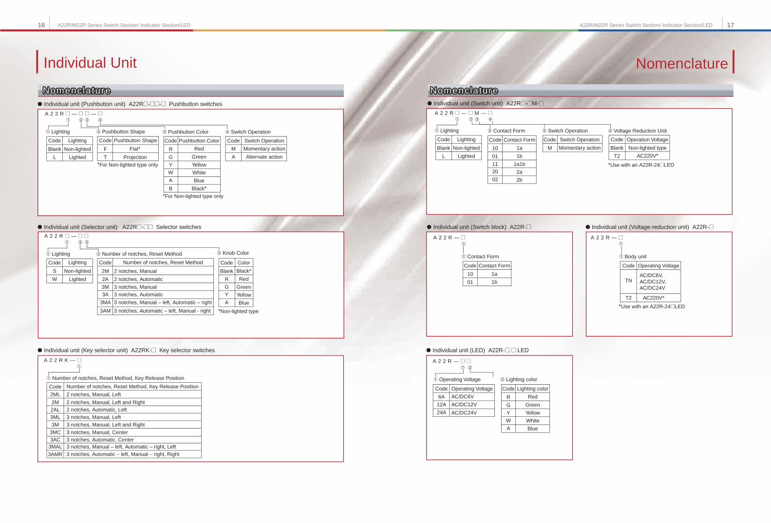
● Individual unit (Switch unit) A22R@-@M-@
● Individual unit (Switch block) A22R-@
● Individual unit (LED) A22R-@ @ LED
● Individual unit (Voltage-reduction unit) A22R-@
A 2 2 R @ — @ M — @➂➁
Switch Operation
Momentary actionM
Code
➀
➁
➁ Contact Form
➃
AC220V*
➃ Voltage Reduction Unit➂ Switch Operation
Operation Voltage
Non-lighted typeBlank
Code
T2
Contact Form
1b
1a10
Code
11
01
1a1b
02
20
2b
2a
A 2 2 R — @
A 2 2 R — @ @
➀
➀
➀ Contact Form
*Use with an A22R-24@LED
Contact Form
1b
1a10
Code
01
AC220V*
*Use with an A22R-24@LED
A 2 2 R — @➀
➀ Body unit
Operating Voltage
AC/DC6V,AC/DC12V,AC/DC24V
TN
T2
Code
Operating Voltage
AC/DC6V
Code
12A
6A
AC/DC12V
24A AC/DC24V
➀ Operating Voltage ➁ Lighting color
Lighting color
Green
RedR
Code
Y
GYellow
A
W
Blue
White
● Individual unit (Pushbutton unit) A22R@-@@-@ Pushbutton switches
A 2 2 R @ — @ @ — @➃➂➁➀
Non-lighted
Code
Blank
L
➀ Lighting
*For Non-lighted type only
*For Non-lighted type only
Pushbutton Color
R
Code
Y
G
B
A
W
Black*
➂ Pushbutton Color ➃ Switch Operation
Code
F
T
➁ Pushbutton Shape
Flat*Pushbutton Shape
Projection
Lighting
Lighted
Switch Operation
Alternate action
Momentary actionM
Code
A
● Individual unit (Selector unit) A22R@-@@ Selector switches
● Individual unit (Key selector unit) A22RK-@ Key selector switches
A 2 2 R @ — @ @➂➁➀
*Non-lighted type
Code
S
W
Color
Red
Black*Blank
Code
G
R
Green
A
Y
Blue
Yellow
➀ Lighting ➁ Number of notches, Reset Method ➂ Knob Color
Number of notches, Reset Method
2 notches, Automatic
2 notches, Manual2M
Code
3M
2A
3 notches, Manual3 notches, Automatic3A
3MA
3AM
3 notches, Manual – left, Automatic – right
3 notches, Automatic – left, Manual - right
➀
➀ Number of notches, Reset Method, Key Release Position
A 2 2 R K — @
Number of notches, Reset Method, Key Release Position
2 notches, Manual, Left and Right
2 notches, Manual, Left
2 notches, Automatic, Left3 notches, Manual, Left3 notches, Manual, Left and Right
3 notches, Manual, Center3 notches, Automatic, Center
2ML
Code
2AL2M
3ML3M
3MC3AC
3MAL
3AMR
3 notches, Manual – left, Automatic – right, Left3 notches, Automatic – left, Manual – right, Right
Individual Unit Nomenclature
NomenclatureNomenclatureNomenclatureNomenclatureNomenclatureNomenclature
Green
Red
Yellow
Blue
White
Non-lighted
Lighting
Lighted
Non-lighted
Code
Blank
L
➀ Lighting
Lighting
Lighted
18 19A22R/M22R Series
Accessories / ToolsAccessories / Tools
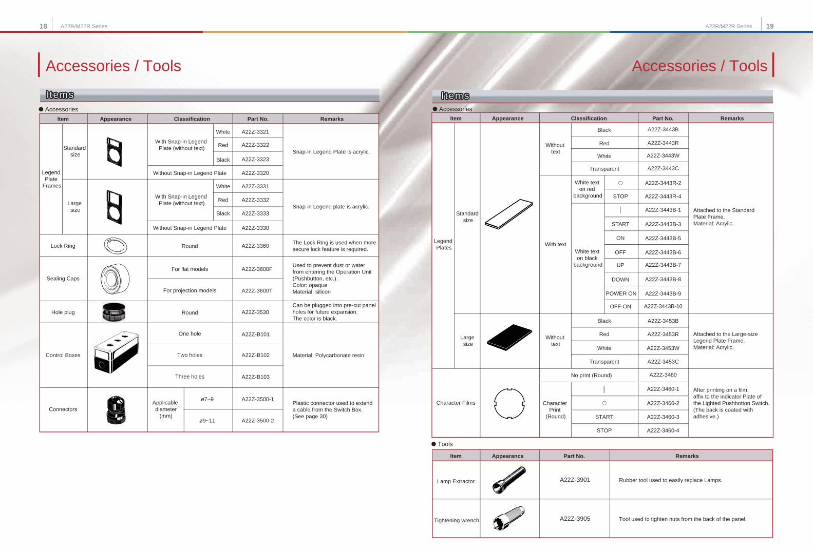
● Accessories
Item Appearance Classification Part No. Remarks
Black
White
Red A22Z-3443R
A22Z-3443W
A22Z-3443C
A22Z-3443R-4
A22Z-3443B-1
A22Z-3443B-5
A22Z-3443B-8
Attached to the Standard Plate Frame.Material: Acrylic.
Transparent
A22Z-3443R-2
│
A22Z-3443B-3
ON
A22Z-3443B-6
A22Z-3443B-7
DOWN
A22Z-3443B-9
A22Z-3443B-10
│
Legend Plates
Standard size
Large size
Without text
With text
A22Z-3443B
STOP
White text on red
background
White text on black
background
START
OFF
UP
POWER ON
OFF-ON
Without text
A22Z-3453B
A22Z-3453R
A22Z-3453W
A22Z-3453C
Attached to the Large-size Legend Plate Frame.Material: Acrylic.
Character Films
No print (Round) A22Z-3460
A22Z-3460-1
Character Print
(Round)
A22Z-3460-2
START A22Z-3460-3
STOP A22Z-3460-4
After printing on a film, affix to the indicator Plate of the Lighted Pushbotton Switch. (The back is coated with adhesive.)
Item Appearance Part No. Remarks
● Tools
Lamp Extractor
Tightening wrench
A22Z-3901 Rubber tool used to easily replace Lamps.
A22Z-3905 Tool used to tighten nuts from the back of the panel.
● Accessories
White
Black
Red
White
Black
Red
A22Z-3322
A22Z-3323
A22Z-3320
A22Z-3331
A22Z-3332
A22Z-3333
A22Z-3330
Snap-in Legend Plate is acrylic.
Snap-in Legend plate is acrylic.
A22Z-3530Can be plugged into pre-cut panel holes for future expansion.The color is black.
Legend Plate
Frames
Standard size
Large size
With Snap-in Legend Plate (without text)
With Snap-in Legend Plate (without text)
Without Snap-in Legend Plate
Without Snap-in Legend Plate
A22Z-3321
Lock Ring Round A22Z-3360The Lock Ring is used when more secure lock feature is required.
Sealing Caps
For flat models
For projection models
A22Z-3600F
A22Z-3600T
Used to prevent dust or water from entering the Operation Unit (Pushbutton, etc.).Color: opaqueMaterial: silicon
Hole plug Round
Control Boxes
One hole
Two holes
Three holes
ConnectorsApplicable diameter
(mm)
A22Z-3500-1
A22Z-3500-2
Plastic connector used to extend a cable from the Switch Box. (See page 30)
ø7~9
ø9~11
A22Z-B101
A22Z-B102
A22Z-B103
Material: Polycarbonate resin.
Item Appearance Classification Part No. Remarks
A22R/M22R Series
I temsItems ItemsItemsItems Items
Black
White
Red
Transparent
20 21A22R/M22R Series A22R/M22R Series
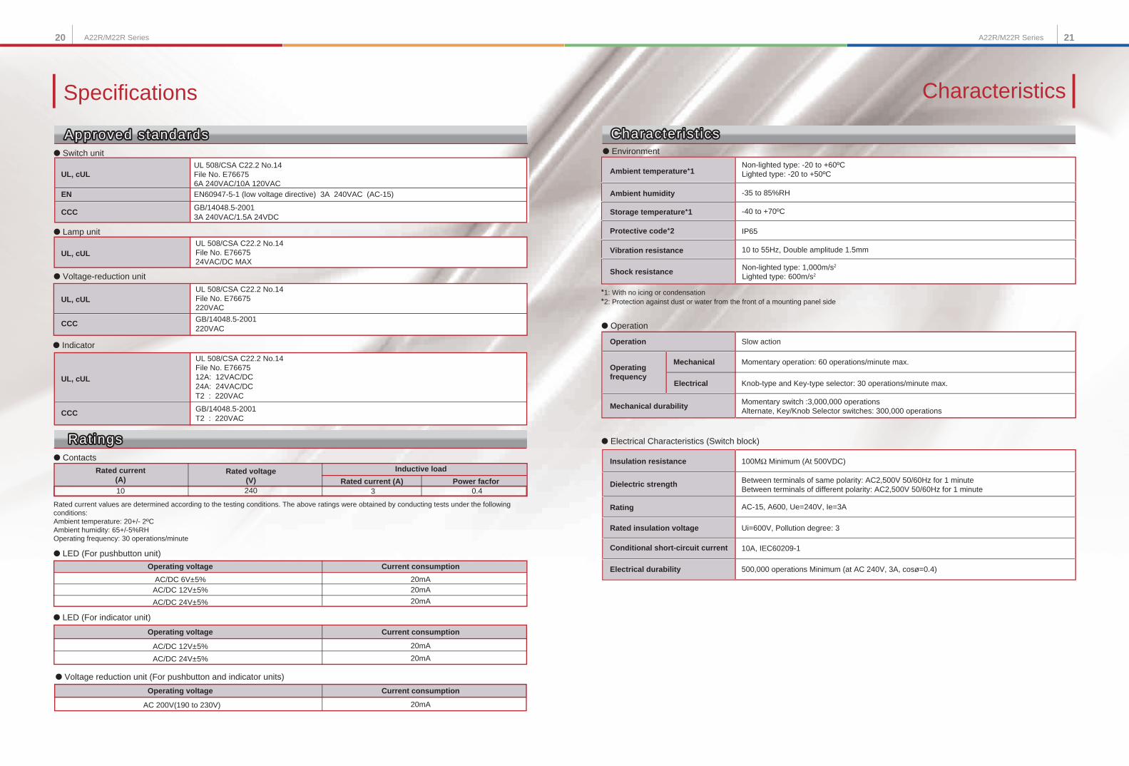
Specifications
● Environment
Non-lighted type: -20 to +60ºCLighted type: -20 to +50ºCAmbient temperature*1
IP65Protective code*2
-40 to +70ºCStorage temperature*1
-35 to 85%RHAmbient humidity
Non-lighted type: 1,000m/s2
Lighted type: 600m/s2Shock resistance
10 to 55Hz, Double amplitude 1.5mmVibration resistance
● Operation
Rating AC-15, A600, Ue=240V, Ie=3A
Rated insulation voltage Ui=600V, Pollution degree: 3
Conditional short-circuit current 10A, IEC60209-1
*1: With no icing or condensation*2: Protection against dust or water from the front of a mounting panel side
Operation Slow action
Momentary operation: 60 operations/minute max.
Knob-type and Key-type selector: 30 operations/minute max.
● Electrical Characteristics (Switch block)
500,000 operations Minimum (at AC 240V, 3A, cosø=0.4)
Insulation resistance 100MΩ Minimum (At 500VDC)
Dielectric strength Between terminals of same polarity: AC2,500V 50/60Hz for 1 minuteBetween terminals of different polarity: AC2,500V 50/60Hz for 1 minute
Momentary switch :3,000,000 operations Alternate, Key/Knob Selector switches: 300,000 operations
Mechanical durability
Operating frequency
Electrical
Electrical durability
Mechanical
EN60947-5-1 (low voltage directive) 3A 240VAC (AC-15)
● Switch unit
● Contacts
UL 508/CSA C22.2 No.14File No. E76675 6A 240VAC/10A 120VAC
UL, cUL
● Lamp unit
● Voltage-reduction unit
EN
● Indicator
CCCGB/14048.5-20013A 240VAC/1.5A 24VDC
UL 508/CSA C22.2 No.14File No. E7667524VAC/DC MAX
UL, cUL
UL 508/CSA C22.2 No.14File No. E76675220VAC
UL, cUL
CCC GB/14048.5-2001220VAC
UL, cUL
CCC
UL 508/CSA C22.2 No.14File No. E7667512A: 12VAC/DC24A: 24VAC/DCT2 : 220VAC
GB/14048.5-2001T2 : 220VAC
● LED (For pushbutton unit)
● LED (For indicator unit)
Rated current (A)
Operating voltage Current consumption
Operating voltage Current consumption
● Voltage reduction unit (For pushbutton and indicator units)
Operating voltage
Inductive load
Power facfor
Current consumption
10 240 3 0.4
AC/DC 6V±5% 20mAAC/DC 12V±5% 20mA
AC/DC 24V±5% 20mA
AC/DC 12V±5% 20mA
AC/DC 24V±5% 20mA
AC 200V(190 to 230V) 20mA
Approved standardsApproved standardsApproved standards
Rat ingsRat ingsRat ings
Rated current values are determined according to the testing conditions. The above ratings were obtained by conducting tests under the following conditions:Ambient temperature: 20+/- 2ºCAmbient humidity: 65+/-5%RHOperating frequency: 30 operations/minute
Rated current(A)
Rated voltage(V)
Character ist icsCharacter ist icsCharacter ist ics
Characteristics
22 23A22R/M22R Series A22R/M22R Series
Characteristics
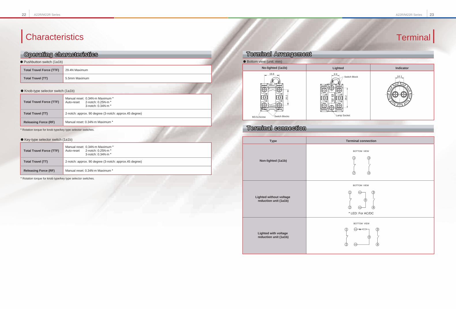
Type
Non-lighted (1a1b)
Lighted without voltage reduction unit (1a1b)
Lighted with voltage reduction unit (1a1b)
Terminal connection
Terminal ArrangementTerminal Arrangement● Bottom view (unit: mm)
20.2
19.8
Switch BlocksM3.5±Screw
9.9
26.2
Switch Block
Lamp Socket
10.1
No-lighted (1a1b) Lighted Indicator
● Pushbutton switch (1a1b)
29.4N Maximum
5.5mm MaximumTotal Travel (TT)
● Knob-type selector switch (1a1b)
● Key-type selector switch (1a1b)
Manual reset: 0.34N·m Maximum *Auto-reset 2-notch: 0.25N·m * 3-notch: 0.34N·m *
Total Travel Force (TTF)
2-notch: approx. 90 degree (3-notch: approx.45 degree)Total Travel (TT)
Manual reset: 0.34N·m Maximum *Releasing Force (RF)
* Rotation torque for knob type/key type selector switches.
Manual reset: 0.34N·m Maximum *Auto-reset 2-notch: 0.25N·m * 3-notch: 0.34N·m *
Total Travel Force (TTF)
2-notch: approx. 90 degree (3-notch: approx.45 degree)Total Travel (TT)
Manual reset: 0.34N·m Maximum *Releasing Force (RF)
* Rotation torque for knob type/key type selector switches.
1
2 4
3
BOTTOM VIEW
* LED: For AC/DC
X2
X1
2
1 3
4
BOTTOM VIEW
x
1
2
X1
X2 4
3
BOTTOM VIEW
x
Operat ing character ist icsOperat ing character ist icsOperat ing character ist ics
Total Travel Force (TTF)
Terminal
Terminal Arrangement
Terminal connect ionTerminal connect ionTerminal connect ion
24 25A22R/M22R Series A22R/M22R Series
Precautions
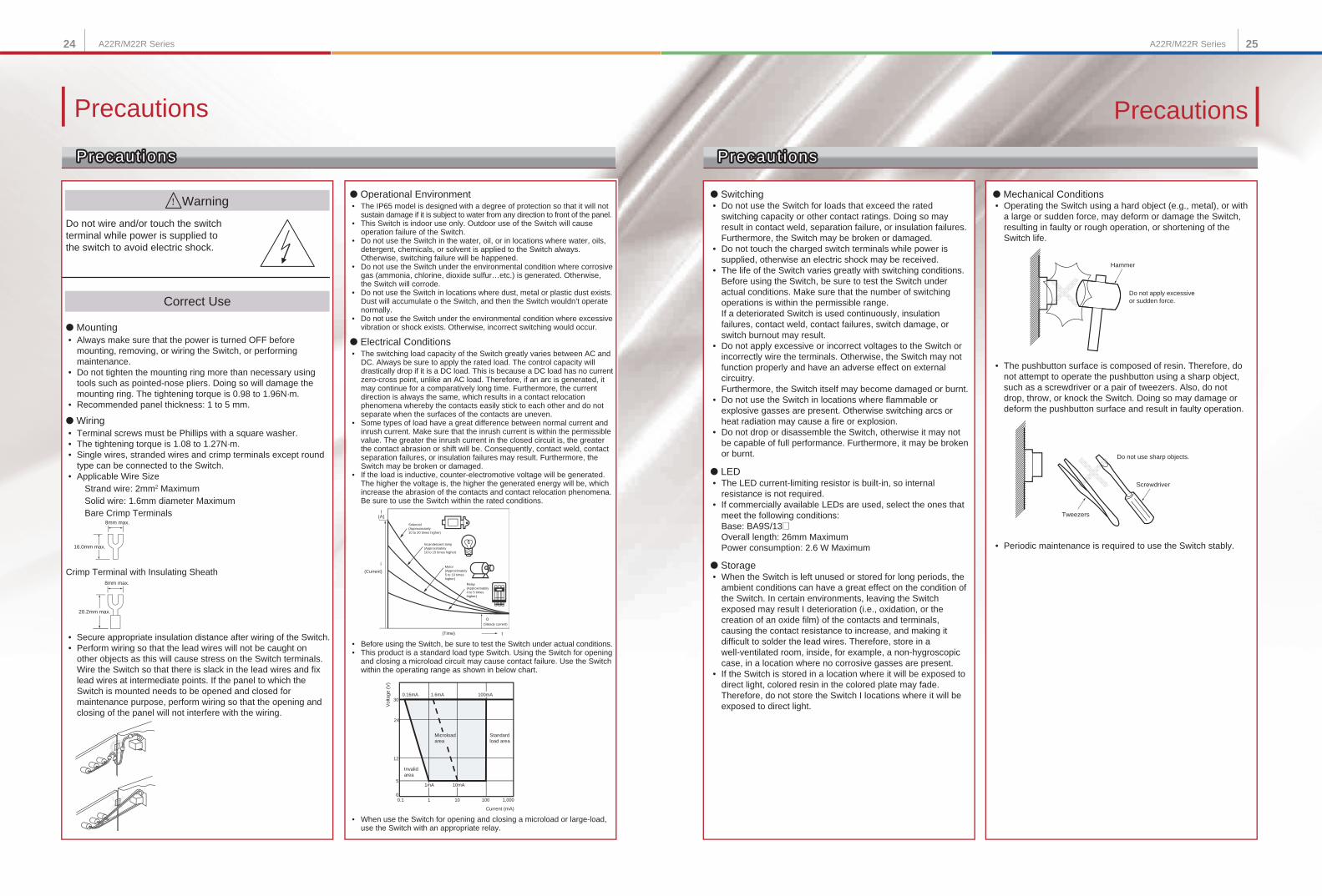
• Do not use the Switch for loads that exceed the rated switching capacity or other contact ratings. Doing so may result in contact weld, separation failure, or insulation failures. Furthermore, the Switch may be broken or damaged. • Do not touch the charged switch terminals while power is supplied, otherwise an electric shock may be received. • The life of the Switch varies greatly with switching conditions. Before using the Switch, be sure to test the Switch under actual conditions. Make sure that the number of switching operations is within the permissible range. If a deteriorated Switch is used continuously, insulation failures, contact weld, contact failures, switch damage, or switch burnout may result. • Do not apply excessive or incorrect voltages to the Switch or incorrectly wire the terminals. Otherwise, the Switch may not function properly and have an adverse effect on external circuitry. Furthermore, the Switch itself may become damaged or burnt. • Do not use the Switch in locations where flammable or explosive gasses are present. Otherwise switching arcs or heat radiation may cause a fire or explosion. • Do not drop or disassemble the Switch, otherwise it may not be capable of full performance. Furthermore, it may be broken or burnt.
● LED • The LED current-limiting resistor is built-in, so internal resistance is not required. • If commercially available LEDs are used, select the ones that meet the following conditions: Base: BA9S/13@ Overall length: 26mm Maximum Power consumption: 2.6 W Maximum
● Storage • When the Switch is left unused or stored for long periods, the ambient conditions can have a great effect on the condition of the Switch. In certain environments, leaving the Switch exposed may result I deterioration (i.e., oxidation, or the creation of an oxide film) of the contacts and terminals, causing the contact resistance to increase, and making it difficult to solder the lead wires. Therefore, store in a well-ventilated room, inside, for example, a non-hygroscopic case, in a location where no corrosive gasses are present. • If the Switch is stored in a location where it will be exposed to direct light, colored resin in the colored plate may fade. Therefore, do not store the Switch I locations where it will be exposed to direct light.
• The pushbutton surface is composed of resin. Therefore, do not attempt to operate the pushbutton using a sharp object, such as a screwdriver or a pair of tweezers. Also, do not drop, throw, or knock the Switch. Doing so may damage or deform the pushbutton surface and result in faulty operation.
• Periodic maintenance is required to use the Switch stably.
● Operational Environment • The IP65 model is designed with a degree of protection so that it will not sustain damage if it is subject to water from any direction to front of the panel. • This Switch is indoor use only. Outdoor use of the Switch will cause operation failure of the Switch. • Do not use the Switch in the water, oil, or in locations where water, oils, detergent, chemicals, or solvent is applied to the Switch always. Otherwise, switching failure will be happened. • Do not use the Switch under the environmental condition where corrosive gas (ammonia, chlorine, dioxide sulfur…etc.) is generated. Otherwise, the Switch will corrode. • Do not use the Switch in locations where dust, metal or plastic dust exists. Dust will accumulate o the Switch, and then the Switch wouldn’t operate normally. • Do not use the Switch under the environmental condition where excessive vibration or shock exists. Otherwise, incorrect switching would occur.
● Electrical Conditions
Do not wire and/or touch the switch terminal while power is supplied to the switch to avoid electric shock.
● Mounting • Always make sure that the power is turned OFF before mounting, removing, or wiring the Switch, or performing maintenance. • Do not tighten the mounting ring more than necessary using tools such as pointed-nose pliers. Doing so will damage the mounting ring. The tightening torque is 0.98 to 1.96N·m. • Recommended panel thickness: 1 to 5 mm.
● Wiring
Solid wire: 1.6mm diameter Maximum Bare Crimp Terminals
Warning
Correct Use
Crimp Terminal with Insulating Sheath
8mm max.
8mm max.
20.2mm max.
• Secure appropriate insulation distance after wiring of the Switch. • Perform wiring so that the lead wires will not be caught on other objects as this will cause stress on the Switch terminals. Wire the Switch so that there is slack in the lead wires and fix lead wires at intermediate points. If the panel to which the Switch is mounted needs to be opened and closed for maintenance purpose, perform wiring so that the opening and closing of the panel will not interfere with the wiring.
• When use the Switch for opening and closing a microload or large-load, use the Switch with an appropriate relay.
• Before using the Switch, be sure to test the Switch under actual conditions. • This product is a standard load type Switch. Using the Switch for opening and closing a microload circuit may cause contact failure. Use the Switch within the operating range as shown in below chart.
0.1 1 10 100 1,000
1mA 10mA5
12
24
300.16mA 1.6mA 100mA
0
o
t
I(A)
i
Precaut ionsPrecaut ionsPrecaut ions
• Terminal screws must be Phillips with a square washer. • The tightening torque is 1.08 to 1.27N·m. • Single wires, stranded wires and crimp terminals except round type can be connected to the Switch. • Applicable Wire Size Strand wire: 2mm2 Maximum
16.0mm max.
• The switching load capacity of the Switch greatly varies between AC and DC. Always be sure to apply the rated load. The control capacity will drastically drop if it is a DC load. This is because a DC load has no current zero-cross point, unlike an AC load. Therefore, if an arc is generated, it may continue for a comparatively long time. Furthermore, the current direction is always the same, which results in a contact relocation phenomena whereby the contacts easily stick to each other and do not separate when the surfaces of the contacts are uneven. • Some types of load have a great difference between normal current and inrush current. Make sure that the inrush current is within the permissible value. The greater the inrush current in the closed circuit is, the greater the contact abrasion or shift will be. Consequently, contact weld, contact separation failures, or insulation failures may result. Furthermore, the Switch may be broken or damaged. • If the load is inductive, counter-electromotive voltage will be generated. The higher the voltage is, the higher the generated energy will be, which increase the abrasion of the contacts and contact relocation phenomena. Be sure to use the Switch within the rated conditions.
Precautions
Precaut ionsPrecaut ionsPrecaut ions
● Mechanical Conditions● Switching • Operating the Switch using a hard object (e.g., metal), or with a large or sudden force, may deform or damage the Switch, resulting in faulty or rough operation, or shortening of the Switch life.
Hammer
Do not apply excessive or sudden force.
Tweezers
Do not use sharp objects.
Screwdriver
Solenoid(Approximately 10 to 20 times higher)
Incandescent lamp(Approximately 10 to 15 times higher)
Relay(Approximately 4 to 5 times higher)
Motor(Approximately 5 to 10 times higher)
(Current)
(Steady current)
Vol
tage
(V
)
Microload area
Standardload area
Invalidarea
Current (mA)
(Time)
A22R/M22R Series A22R/M22R Series
Installation Installation
Mount ing to the PanelMount ing to the PanelMount ing to the Panel How to conf i rm the Lever Posi t ion, OPEN or LOCKHow to conf i rm the Lever Posi t ion, OPEN or LOCKHow to conf i rm the Lever Posi t ion, OPEN or LOCK
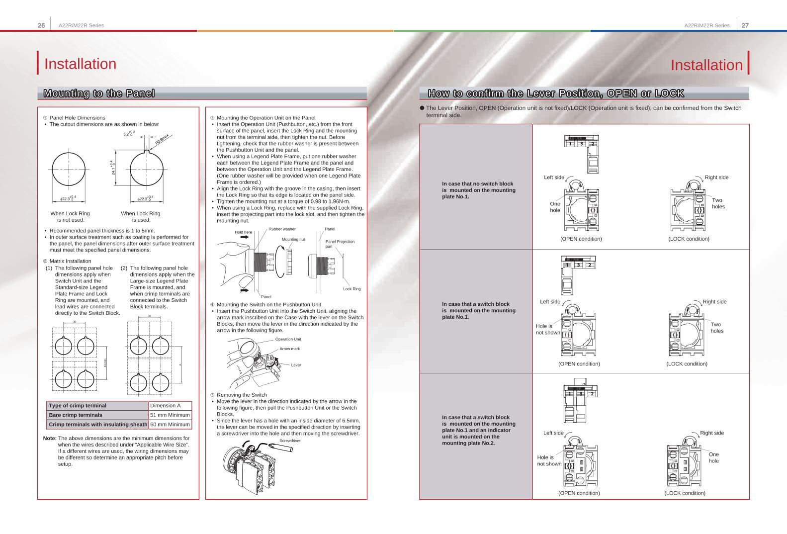
➀ Panel Hole Dimensions • The cutout dimensions are as shown in below:
➂ Mounting the Operation Unit on the Panel • Insert the Operation Unit (Pushbutton, etc.) from the front
surface of the panel, insert the Lock Ring and the mounting nut from the terminal side, then tighten the nut. Before tightening, check that the rubber washer is present between the Pushbutton Unit and the panel.
• When using a Legend Plate Frame, put one rubber washer each between the Legend Plate Frame and the panel and between the Operation Unit and the Legend Plate Frame. (One rubber washer will be provided when one Legend Plate Frame is ordered.)
• Align the Lock Ring with the groove in the casing, then insert the Lock Ring so that its edge is located on the panel side.
• Tighten the mounting nut at a torque of 0.98 to 1.96N·m. • When using a Lock Ring, replace with the supplied Lock Ring,
insert the projecting part into the lock slot, and then tighten the mounting nut.
When Lock Ring is not used.
When Lock Ring is used.
• Recommended panel thickness is 1 to 5mm. • In outer surface treatment such as coating is performed for
the panel, the panel dimensions after outer surface treatment must meet the specified panel dimensions.
➁ Matrix Installation(1) The following panel hole
dimensions apply when Switch Unit and the Standard-size Legend Plate Frame and Lock Ring are mounted, and lead wires are connected directly to the Switch Block.
(2) The following panel hole dimensions apply when the Large-size Legend Plate Frame is mounted, and when crimp terminals are connected to the Switch Block terminals.
Type of crimp terminal
Crimp terminals with insulating sheath
Bare crimp terminals
Dimension A
60 mm Minimum
51 mm Minimum
Note: The above dimensions are the minimum dimensions for when the wires described under “Applicable Wire Size”. If a different wires are used, the wiring dimensions may be different so determine an appropriate pitch before setup.
Rubber washerHold here
Mounting nut
Panel
Panel
Panel Projection part
Lock Ring
➃ Mounting the Switch on the Pushbutton Unit • Insert the Pushbutton Unit into the Switch Unit, aligning the
arrow mark inscribed on the Case with the lever on the Switch Blocks, then move the lever in the direction indicated by the arrow in the following figure.
Operation Unit
Arrow mark
Lever
Screwdriver
➄ Removing the Switch • Move the lever in the direction indicated by the arrow in the
following figure, then pull the Pushbutton Unit or the Switch Blocks.
• Since the lever has a hole with an inside diameter of 6.5mm, the lever can be moved in the specified direction by inserting a screwdriver into the hole and then moving the screwdriver.
● The Lever Position, OPEN (Operation unit is not fixed)/LOCK (Operation unit is fixed), can be confirmed from the Switch terminal side.
In case that no switch block is mounted on the mounting plate No.1.
Left side
(OPEN condition) (LOCK condition)
Right side
One hole
Two holes
Left side
(OPEN condition) (LOCK condition)
Right side
Hole is not shown
Two holes
Left side
(OPEN condition) (LOCK condition)
Right side
Hole is not shown
One hole
In case that a switch block is mounted on the mounting plate No.1.
In case that a switch block is mounted on the mounting plate No.1 and an indicator unit is mounted on the mounting plate No.2.
45 m
in.
28 29A22R/M22R Series A22R/M22R Series
Installation
Mount ing/Replacing the Switch Uni t and Indicator Uni tMount ing/Replacing the Switch Uni t and Indicator Uni t
Instal l ing/Replacing the LEDInstal l ing/Replacing the LED
Mount ing/Replacing the Color CapMount ing/Replacing the Color Cap
Assembl ing the CapAssembl ing the Cap
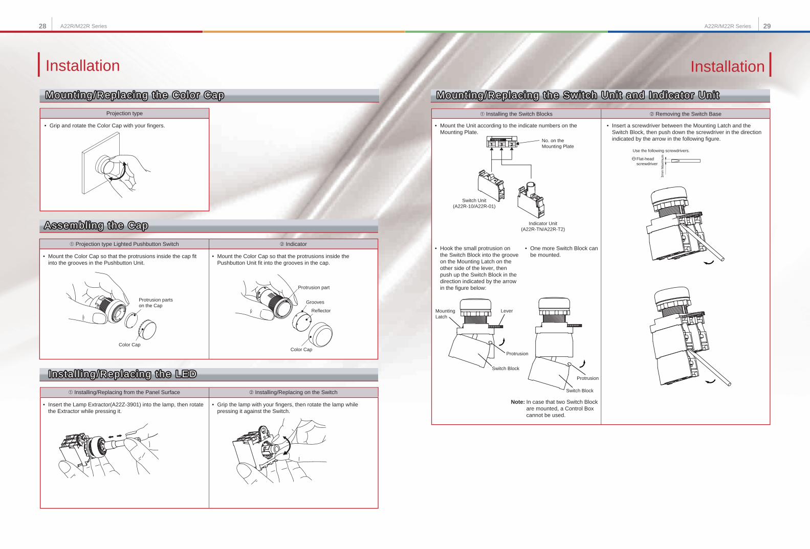
➀ Projection type Lighted Pushbutton Switch
• Mount the Color Cap so that the protrusions inside the cap fit into the grooves in the Pushbutton Unit.
• Mount the Color Cap so that the protrusions inside the Pushbutton Unit fit into the grooves in the cap.
➁ Indicator
Projection type
• Grip and rotate the Color Cap with your fingers.
Protrusion parts on the Cap
Color Cap
Reflector
Protrusion part
Grooves
Color Cap
• Mount the Unit according to the indicate numbers on the Mounting Plate.
Switch Unit(A22R-10/A22R-01)
Indicator Unit(A22R-TN/A22R-T2)
No. on the Mounting Plate
• Hook the small protrusion on the Switch Block into the groove on the Mounting Latch on the other side of the lever, then push up the Switch Block in the direction indicated by the arrow in the figure below:
Mounting Latch
Lever
Protrusion
Switch Block
• One more Switch Block can be mounted.
Note: In case that two Switch Block are mounted, a Control Box cannot be used.
Protrusion
Switch Block
• Insert a screwdriver between the Mounting Latch and the Switch Block, then push down the screwdriver in the direction indicated by the arrow in the following figure.
Use the following screwdrivers.
3mm
Max
imumFlat-head
screwdriver
• Insert the Lamp Extractor(A22Z-3901) into the lamp, then rotate the Extractor while pressing it.
• Grip the lamp with your fingers, then rotate the lamp while pressing it against the Switch.
Installation
Mount ing/Replacing the Switch Uni t and Indicator Uni t
Instal l ing/Replacing the LED
Mount ing/Replacing the Color Cap
Assembl ing the Cap
➀ Installing/Replacing from the Panel Surface ➁ Installing/Replacing on the Switch
➀ Installing the Switch Blocks ➁ Removing the Switch Base
30 31A22R/M22R Series A22R/M22R Series
• Engrave the characters directly on the matted side of the Snap-in Legend Plate. • The characters must be engraved no deeper than 0.5mm. • Apply alcohol-based paint coating to the engraved characters. • If the Snap-in Legend Plate is transparent, engrave the mirror-written characters on the back of the Snap-in Legend Plate and apply paint coating of a different color to the remaining part of the Snap-in Legend Plate.
Material: Acrylic
• Hold the Cap, remove the cardboard o the Film, and attach the Film to the Cap. Make sure that the protruding portions of the Cap engage the cutout portions of the Film and that the characters are aligned parallel to the imaginary line connecting the two protruding portions to the left and right of the Cap.
• Press and secure the Snap-in Legend Plate onto the Legend Plate Frame. • The direction of the characters will vary with the mounting direction of the control panel if the Switch is a knob or key selector model.
• To easily remove the Snap-in Legend Plate from the Legend Plate Frame mounted to the panel. Insert a Tool with a thin tip into the space between the Snap-in Legend Plate and the Legend Plate Frame.
• The Snap-in Legend Plate is easily removed by pressing the Snap-I Legend Plate from the back of the Legend Plate Frame. • The Legend Plate Frame is made of acrylic resin, which is easily damaged by shock. Be sure to handle the Legend Plate Frame with care.
• Lock Ring (A22Z-3360) cannot be used. • When use the Legend Plate Frames (A22Z-332 @ , A22Z-333 @) cut the projection portions shown in the below fig.
• When use the Control Box (A22Z-B10 @), cut the projection portions shown in the below fig.
Cut the projection portions
Cut the projection portions
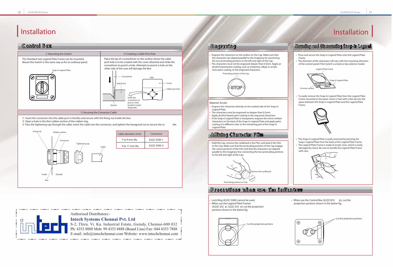
The Standard-size Legend Plate Frame can be mounted. Mount the Switch in the same way as for an ordinary panel.
Place the tip of a screwdriver on the surface where the cable port hole is to be created with the cover attached and strike the screwdriver to punch a hole. Attempts to punch a hole on the other side of the case will damage the Box.
Insert the connector into the cable port in the Box and secure with the fixing nut inside the box. Open a hole in the thin rubber section of the rubber ring. Pass the tightening cap through the cable, insert the cable into the connector, and tighten the hexagonal nut to secure the ca ble.
7 to 9 mm dia.
9 to 11 mm dia.
A22Z-3500-1
A22Z-3500-2
Cable diameter (mm) Connector
Snap-in Legend Plate
Screwdriver
Strike the screwdriver to punch a hole by place 4 parts diagonally.
Installation
Mounting the Switch Creating a Cable Port Hole
Securing the Connector Cable
Installation
Engraving
Precaut ions when use the Indicators
Mounting and Dismounting Snap- in LegendControl Box
Affixing Character F i lm
Engraving
Precaut ions when use the Indicators
Mounting and Dismounting Snap- in LegendControl Box
Affixing Character F i lmFixing nut Rubber washer
Connector
Tightening cap
Cable
Inside
Box
Outside
• Engrave the characters on the surface on the Cap. Make sure that the characters are aligned parallel to the imaginary lie connecting the two protruding portions to the left and right of the Cap. • The characters must not be engraved deeper than 0.5mm. Apply an alcohol-based paint coating, such as melamine, alkyd, or acrylic resin paint coating, to the engraved characters.
Protruding portions of the Cap
Legend Plate Frame
Snap-in Legend Plate
Concave surface
Remove the cardboard.
Protruding portions on Cap
Side
Cover
Cable port hole
Switch box
Groove
Authorised Distributors:-
Intech Systems Chennai Pvt. LtdS-2, Thiru. Vi. Ka. Industrial Estate, Guindy, Chennai-600 032
Ph: 4353 8888 Mob: 99 4353 8888 (Board Line) Fax: 044 4353 7888
E-mail: [email protected] Website: www.intechchennai.com