Embed Size (px)
Citation preview
Abstract—This paper proposes a new H-infinity robust
control strategy for a grid-connected doubly fed induction
generator based wind turbine (DFIG-WT) to improve transient
stability during uncertainties and grid faults. A linearization
scheme for the dynamic model of a DFIG is proposed, in which
state space representation of DFIG has been derived in the
stator-flux and grid-oriented reference frames. DC link voltage
and rotor speed are selected and incorporated into the input
disturbances in the input signals to enhance the stability of the
H-infinity controller. Appropriate controllers are synthesized
simultaneously for the rotor and grid side convertors of the
DFIG subject to worst case disturbance. Extensive simulation
studies are carried out on a 1.5 MW DFIG-WT connected to a
power system consisting of a double-circuit transmission line.
This is done to examine the operation and effectiveness of the
proposed control method under disturbances and grid faults.
As per simulation results, the proposed H-infinity controller
provides improved and superior performance in terms of
damped oscillations and less severe voltage dip in comparison
with the commonly used PI controller.
Index Terms— Doubly fed induction generator (DFIG), grid
faults, H-infinity control, power system stability, wind power
generation
I. INTRODUCTION
URING the last decades, the integration of renewable
energy units such as wind power generation into the
existing power system has been increasing, leading to high
penetration of wind turbines (WT). The high penetration of
WT in the power system, however, raises critical challenges
with regard to the power quality in normal conditions and
the grid stability during grid faults. Therefore, it has been
recognized that WT controllers should play a critical role in
the stability performance of grid-connected WT.
A doubly fed induction generator (DFIG) is a dominant
type in wind power generation because of its advanced
active/reactive power controllability. In order to fully utilize
its controllability, DFIG controllers must be designed
carefully and appropriately. However, the control of DFIGs
has proven to be a difficult task because of several reasons
including, nonlinear system dynamics, multivariable system,
and unmeasurable state variables.
The vector control strategy is used for active and reactive
power control of the DFIG-WT. Traditionally, the control
function in the vector control is performed by PI control
Manuscript received July 03, 2016; revised August 04, 2016.
S. Khoete, Y. Manabe, M. Kurimoto, T. Funabashi, and T. Kato are
with the Department of Electrical Engineering at Nagoya University,
Nagoya, Japan (phone: +81 052 789 2036; fax: +81 052 789 2108; e-mail:
because it is simple and relatively easy to implement.
However, because of the nonlinearity of the DFIG electrical
dynamics, the conventional PI control methods are not ideal
during uncertainties and grid faults. According to [1], there
are two drawbacks associated with implementing PI current
regulators in the DFIG design. Firstly, the discrete operation
of the convertors is not taken into account. Secondly, the
DFIG is modelled as a linear time-invariant system. Based
on these simplifying assumptions, the gains of the PI
controller are tuned using the small signal analysis of the
nonlinear equations describing the DFIG behavior.
Consequently, the system formulation is only valid around a
specific operation condition, although the system is required
to work properly at operating conditions largely deviated
from nominal condition such as during grid faults.
The major concern in the design of advanced controllers
for power systems is the ability of the control scheme to
perform satisfactorily under a broad range of operating
conditions that may involve uncertainties [3]. This is
referred to as robustness capability. Robustness is
particularly important in the DFIG control design in order to
synthesize controllers that can maintain a high performance
during grid disturbances and parameter uncertainties. There
are some preceding studies based on the application of
advanced control of the DFIG. For example, in [2], the
authors developed a goal heuristic dynamic programming
(GHrDP) based controller for the DFIG to improve transient
stability during disturbances. Another study was done in [4],
in which a nonlinear control method for a DFIG using
differential geometry theory is proposed and compared with
the traditional PI method. However, this method does not
show significant improvement in the results. Reference [5]
presents a sensitivity analysis approach based on both
trajectory and frequency domain information integrated with
evolutionary algorithm to achieve the optimal control of
DFIG-WT, although this method does not take the
nonlinearity of the DFIG into consideration during the
controller design.
H-infinity control is one of the promising control schemes
to overcome the above described drawbacks in the
conventional control schemes. The robust H-infinity control
has been studied extensively in the last three decades.
Typical applications for robust control include systems that
have high requirements for robustness to parameter
variations and high requirements performances. The
formulation of the H-infinity control problem is based on the
minimization of a quadratic cost function that comprises
both the disturbance and control input effects. One of the
key features of H-infinity technique is the minimization of
Robust H-infinity Control for DFIG to Enhance
Transient Stability during Grid Faults
Sebastian Khoete, Yusuke Manabe, Muneaki Kurimoto, Toshihisa Funabashi and Takeyoshi Kato
D
Proceedings of the World Congress on Engineering and Computer Science 2016 Vol II WCECS 2016, October 19-21, 2016, San Francisco, USA
ISBN: 978-988-14048-2-4 ISSN: 2078-0958 (Print); ISSN: 2078-0966 (Online)
WCECS 2016
noises and external disturbances without making
assumptions on them.
However, there is barely any researches done to evaluate
the performance of H-infinity control in the DFIG in order to
improve transient stability during grid faults. A study based
specially on the application of H-infinity control to wind
power generation was done in [3], where a pitch control
scheme and a model based H-infinity synthesis controller
that yields a multivariable control law governing operation
of the power electronic converter for a megawatt class DFIG
over the entire operating trajectory is proposed. However,
this study only focuses on pitch control of the WT during
high wind turbulence. It does not investigate the behavior of
the power system during grid and other disturbances. It also
does not show comparison with other conventional methods.
In light of the above mentioned shortcomings, this study
aims to propose a useful DFIG-WT control design strategy
based on H-infinity control to improve transient stability
during grid faults. Since robustness is an important issue in
control systems design, special focus is placed on robustness
of the system to external disturbances. To design the H-
infinity controller, initially the system is represented in a
standard configuration. Variables in the standard
configuration, especially the exogenous input variables, are
carefully selected and evaluated such that optimum
controller performance is achieved.
The organization of this paper is as follows. Section II
provides the mathematical modeling of the power system
components under consideration and the theory of vector
control. The proposed H-infinity control design algorithm
and objectives are presented in Section III. In Section IV,
the performance of the H-infinity, as well as PI controller, is
demonstrated through a series of simulation results. Detailed
interpretation of simulation results is also done in this
section. Finally, concluding remarks are given in Section V.
II. SYSTEM CONFIGURATION AND MODELING
A. DFIG Model Configuration
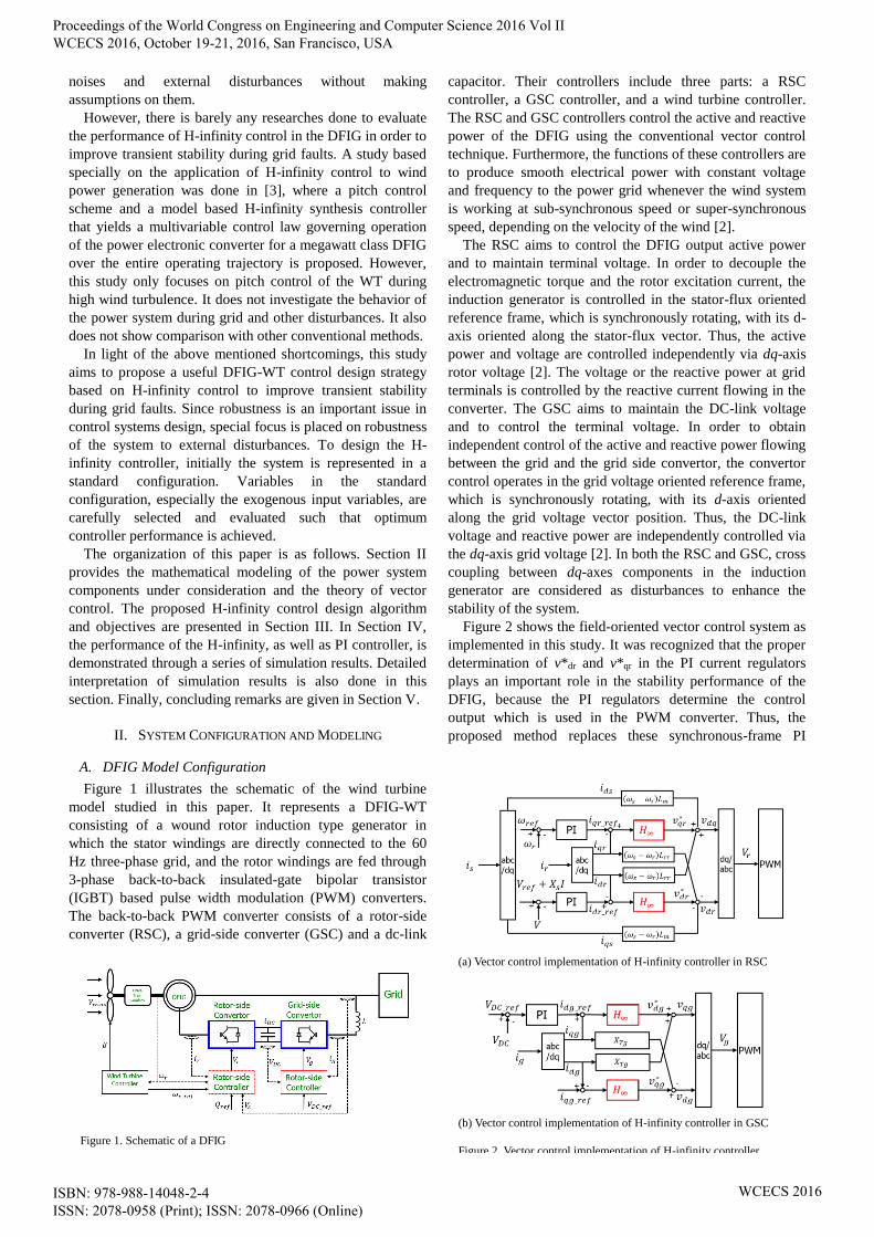
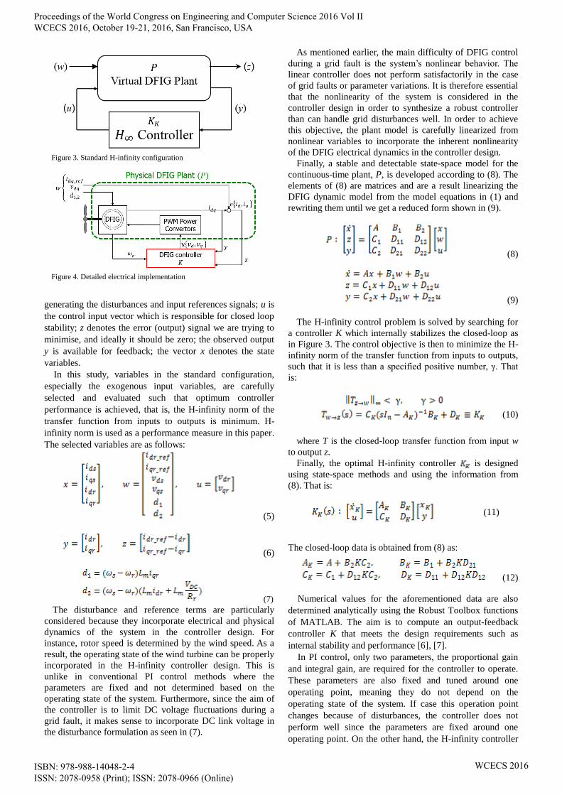
Figure 1 illustrates the schematic of the wind turbine
model studied in this paper. It represents a DFIG-WT
consisting of a wound rotor induction type generator in
which the stator windings are directly connected to the 60
Hz three-phase grid, and the rotor windings are fed through
3-phase back-to-back insulated-gate bipolar transistor
(IGBT) based pulse width modulation (PWM) converters.
The back-to-back PWM converter consists of a rotor-side
converter (RSC), a grid-side converter (GSC) and a dc-link
capacitor. Their controllers include three parts: a RSC
controller, a GSC controller, and a wind turbine controller.
The RSC and GSC controllers control the active and reactive
power of the DFIG using the conventional vector control
technique. Furthermore, the functions of these controllers are
to produce smooth electrical power with constant voltage
and frequency to the power grid whenever the wind system
is working at sub-synchronous speed or super-synchronous
speed, depending on the velocity of the wind [2].
The RSC aims to control the DFIG output active power
and to maintain terminal voltage. In order to decouple the
electromagnetic torque and the rotor excitation current, the
induction generator is controlled in the stator-flux oriented
reference frame, which is synchronously rotating, with its d-
axis oriented along the stator-flux vector. Thus, the active
power and voltage are controlled independently via dq-axis
rotor voltage [2]. The voltage or the reactive power at grid
terminals is controlled by the reactive current flowing in the
converter. The GSC aims to maintain the DC-link voltage
and to control the terminal voltage. In order to obtain
independent control of the active and reactive power flowing
between the grid and the grid side convertor, the convertor
control operates in the grid voltage oriented reference frame,
which is synchronously rotating, with its d-axis oriented
along the grid voltage vector position. Thus, the DC-link
voltage and reactive power are independently controlled via
the dq-axis grid voltage [2]. In both the RSC and GSC, cross
coupling between dq-axes components in the induction
generator are considered as disturbances to enhance the
stability of the system.
Figure 2 shows the field-oriented vector control system as
implemented in this study. It was recognized that the proper
determination of v*dr and v*qr in the PI current regulators
plays an important role in the stability performance of the
DFIG, because the PI regulators determine the control
output which is used in the PWM converter. Thus, the
proposed method replaces these synchronous-frame PI
Figure 1. Schematic of a DFIG
(a) Vector control implementation of H-infinity controller in RSC
(b) Vector control implementation of H-infinity controller in GSC
Figure 2. Vector control implementation of H-infinity controller
Proceedings of the World Congress on Engineering and Computer Science 2016 Vol II WCECS 2016, October 19-21, 2016, San Francisco, USA
ISBN: 978-988-14048-2-4 ISSN: 2078-0958 (Print); ISSN: 2078-0966 (Online)
WCECS 2016
current regulators with the robust H-infinity controllers as
shown in Figure 2. Appropriate controllers are synthesized
for the RSC and GSC. This is because the machine operation
is fully controlled through the RSC, while GSC is mainly
targeted to maintain DC link voltage because the RSC
requires a constant voltage supply to operate. Therefore, the
proposed H-infinity control strategy in this study aims to
limit DC voltage fluctuations and to limit inrush rotor
current during grid faults to protect the RSC and the rest of
the power system.
In order to make a comparative analysis, the PI controllers
designed in this study are of first order ( + ), which
have the same input and output signals as the designed H-
infinity controller. The PI controller parameters are tuned by
trial-and-error approach.
B. DFIG Model Configuration
In this study, the space vector approach is adopted for the
dynamic modelling of the electrical system, based on the
fifth-order two-axis representation. The fifth-order dynamic
equations describing the doubly fed induction generator are
obtained by transforming the standard three-phase induction
machine equations into a synchronously rotating reference
frame in the direct and quadrature axes based on the current
direction [3].
The respective three-phase stator and rotor voltages are
obtained by the following DFIG electrical equations:
(1)
where and are stator and rotor winding voltages; ,
, and are the stator and rotor winding resistances and
currents; , , are the reference, nominal and
generator speeds, respectively, and are stator and
rotor fluxes. The three phase quantities: voltages and fluxes
can be determined as follows [3].
(2)
,
where ; is the synchronous speed
(rotational speed of the magnetic field); is the rotor
rotational/electrical speed; and are stator and rotor
winding resistances; subscripts d and q mean the dq-axis
components. The flux linkages are expressed by the
following sets of equations:
(3)
where and are stator and rotor winding inductances,
and is the mutual inductance.
A. DFIG Model Configuration
The drive train of the DFIG consists of a turbine, a low
and high speed shaft, and a gearbox that connects to the
generator. The system adopted in this study is a two-mass
model and it is represented by [2]:
(4)
Where the inertia constants of the turbine; the inertia
constants of the generator; the angle speed; the
generator rotor angle speed; the shaft twist angle;
the shaft stiffness coefficient; the damping coefficient;
the shaft torque; the wind torque; the
electromagnetic torque.
III. H-INFINITY CONTROL DESIGN
A. H-infinity control principle
In this study, the proposed H-infinity controller achieves
robustness in the DFIG by controlling the electrical power
exchanged between the stator and the grid power. It does
this by controlling the active and reactive power
independently. It also aims to limit voltage fluctuations
during and after a grid fault. By so doing, it gives improved
tracking response and good robustness against the machine’s
parameter variations. One of the advantages of H-infinity is
its ability to stabilize internal dynamics. The basic concept
of H-infinity control is to allow for uncertainty in the design
of the fixed controller, thus, producing a robust controller
that is insensitive to parameter variations or disturbances [3].
The major drawback of the proposed method is that it comes
at a cost of computational burden and could be hard to
realize in practice.
B. DFIG Model Configuration
The proposed H-infinity control method makes use of a
generator model that is locally linearized and is used to
compute the control law. The known robustness features of
the H-infinity control enable to compensate for the errors of
the approximate linearization, as well as eliminate the effects
of external disturbances. To perform the linearization,
dynamic equations are first derived from electrical equations
in (1). These dynamic equations are then written in state-
space form using (9).
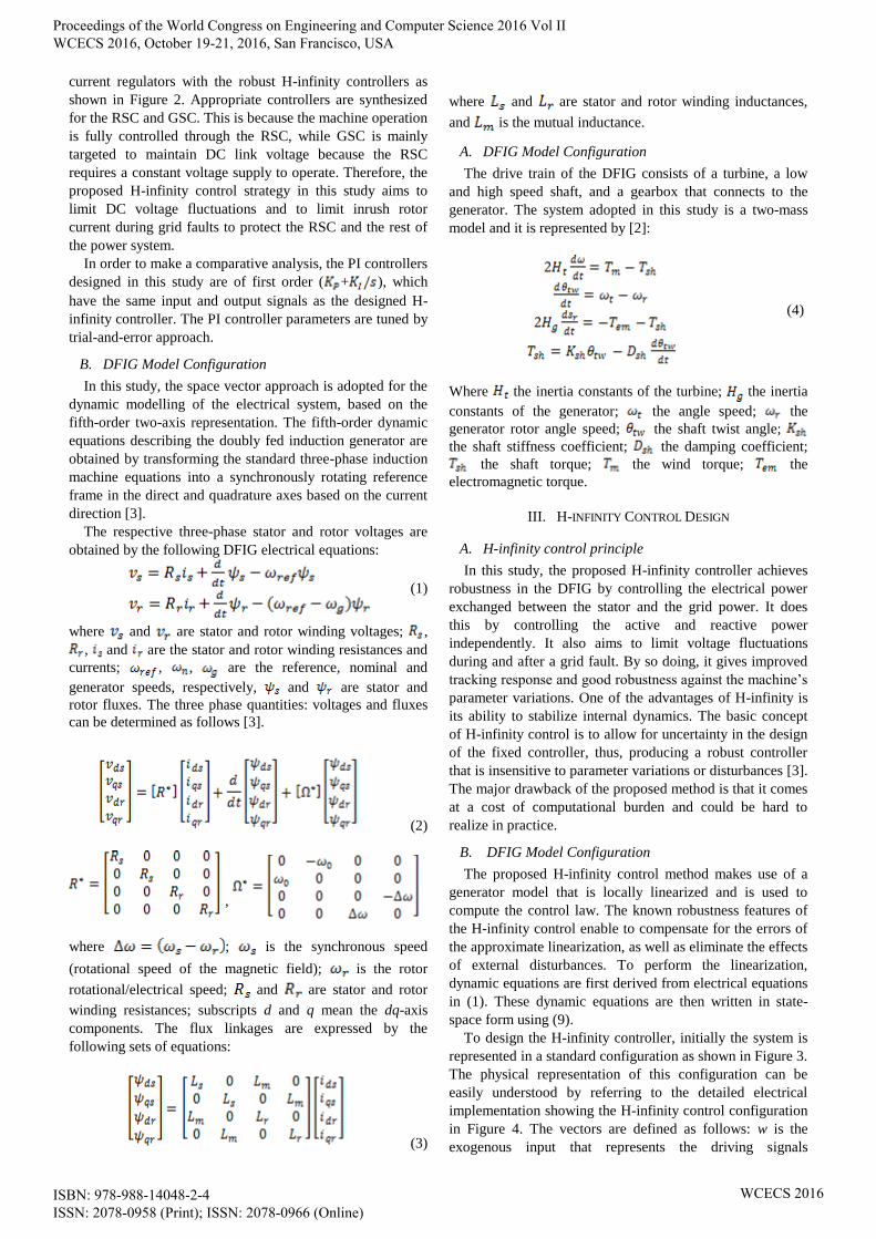
To design the H-infinity controller, initially the system is
represented in a standard configuration as shown in Figure 3.
The physical representation of this configuration can be
easily understood by referring to the detailed electrical
implementation showing the H-infinity control configuration
in Figure 4. The vectors are defined as follows: w is the
exogenous input that represents the driving signals
Proceedings of the World Congress on Engineering and Computer Science 2016 Vol II WCECS 2016, October 19-21, 2016, San Francisco, USA
ISBN: 978-988-14048-2-4 ISSN: 2078-0958 (Print); ISSN: 2078-0966 (Online)
WCECS 2016
generating the disturbances and input references signals; u is
the control input vector which is responsible for closed loop
stability; z denotes the error (output) signal we are trying to
minimise, and ideally it should be zero; the observed output
y is available for feedback; the vector x denotes the state
variables.
In this study, variables in the standard configuration,
especially the exogenous input variables, are carefully
selected and evaluated such that optimum controller
performance is achieved, that is, the H-infinity norm of the
transfer function from inputs to outputs is minimum. H-
infinity norm is used as a performance measure in this paper.
The selected variables are as follows:
(5)
(6)
(7)
The disturbance and reference terms are particularly
considered because they incorporate electrical and physical
dynamics of the system in the controller design. For
instance, rotor speed is determined by the wind speed. As a
result, the operating state of the wind turbine can be properly
incorporated in the H-infinity controller design. This is
unlike in conventional PI control methods where the
parameters are fixed and not determined based on the
operating state of the system. Furthermore, since the aim of
the controller is to limit DC voltage fluctuations during a
grid fault, it makes sense to incorporate DC link voltage in
the disturbance formulation as seen in (7).
As mentioned earlier, the main difficulty of DFIG control
during a grid fault is the system’s nonlinear behavior. The
linear controller does not perform satisfactorily in the case
of grid faults or parameter variations. It is therefore essential
that the nonlinearity of the system is considered in the
controller design in order to synthesize a robust controller
than can handle grid disturbances well. In order to achieve
this objective, the plant model is carefully linearized from
nonlinear variables to incorporate the inherent nonlinearity
of the DFIG electrical dynamics in the controller design.
Finally, a stable and detectable state-space model for the
continuous-time plant, P, is developed according to (8). The
elements of (8) are matrices and are a result linearizing the
DFIG dynamic model from the model equations in (1) and
rewriting them until we get a reduced form shown in (9).
(8)
(9)
The H-infinity control problem is solved by searching for
a controller K which internally stabilizes the closed-loop as
in Figure 3. The control objective is then to minimize the H-
infinity norm of the transfer function from inputs to outputs,
such that it is less than a specified positive number, γ. That
is:
(10)
where T is the closed-loop transfer function from input w
to output z.
Finally, the optimal H-infinity controller is designed
using state-space methods and using the information from
(8). That is:
(11)
The closed-loop data is obtained from (8) as:
(12)
Numerical values for the aforementioned data are also
determined analytically using the Robust Toolbox functions
of MATLAB. The aim is to compute an output-feedback
controller K that meets the design requirements such as
internal stability and performance [6], [7].
In PI control, only two parameters, the proportional gain
and integral gain, are required for the controller to operate.
These parameters are also fixed and tuned around one
operating point, meaning they do not depend on the
operating state of the system. If case this operation point
changes because of disturbances, the controller does not
perform well since the parameters are fixed around one
operating point. On the other hand, the H-infinity controller
Figure 3. Standard H-infinity configuration
Figure 4. Detailed electrical implementation
Proceedings of the World Congress on Engineering and Computer Science 2016 Vol II WCECS 2016, October 19-21, 2016, San Francisco, USA
ISBN: 978-988-14048-2-4 ISSN: 2078-0958 (Print); ISSN: 2078-0966 (Online)
WCECS 2016
in this study is designed to perform well regardless of the
changing operating points. This is because the design
incorporates the dynamics of the system in the controller
design. The controller design makes use of a virtual plant
model to estimate the controller parameters. This virtual
plant is different from the physical plant of the DFIG which
represents the process which is controlled by the control
output. The virtual model can be visualized as in Figure 3
while Figure 4 can be thought of the physical process.
IV. SIMULATION RESULTS
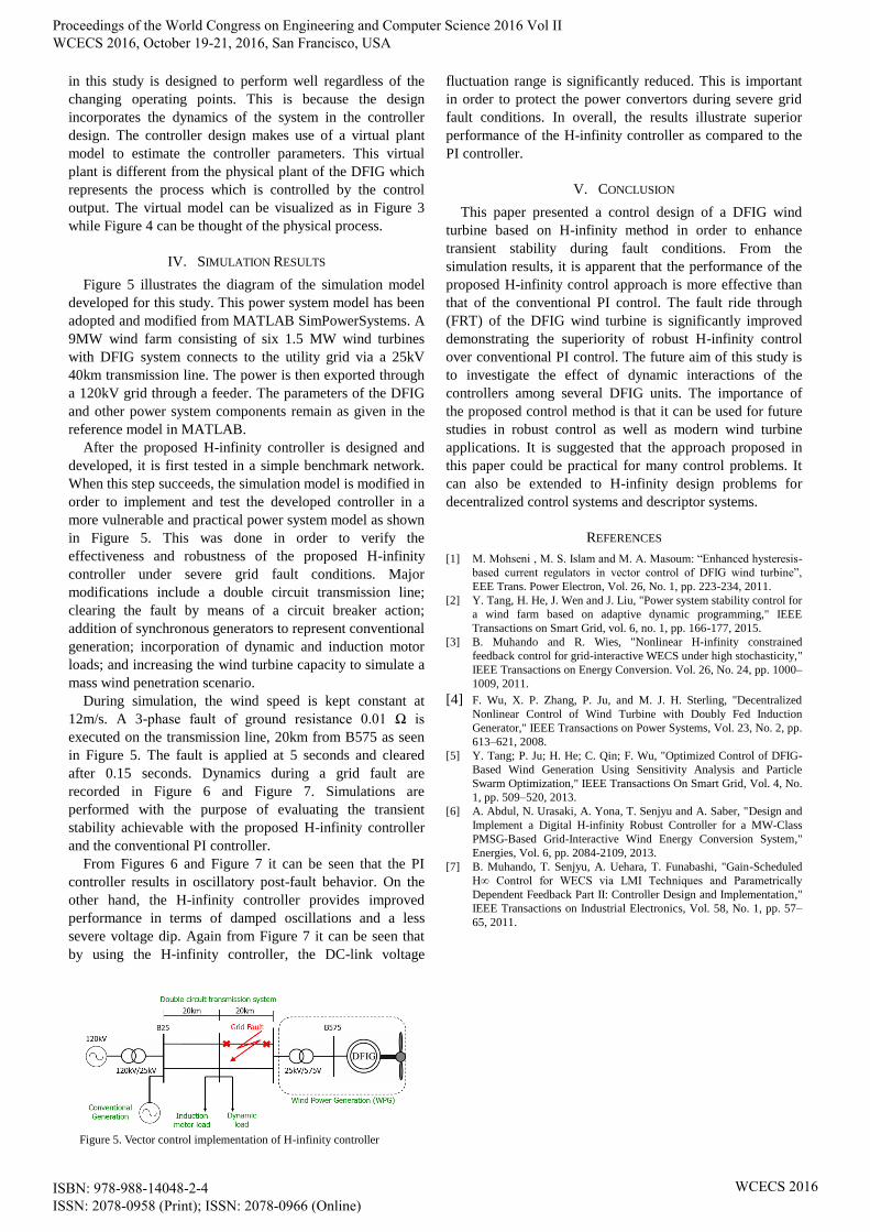
Figure 5 illustrates the diagram of the simulation model
developed for this study. This power system model has been
adopted and modified from MATLAB SimPowerSystems. A
9MW wind farm consisting of six 1.5 MW wind turbines
with DFIG system connects to the utility grid via a 25kV
40km transmission line. The power is then exported through
a 120kV grid through a feeder. The parameters of the DFIG
and other power system components remain as given in the
reference model in MATLAB.
After the proposed H-infinity controller is designed and
developed, it is first tested in a simple benchmark network.
When this step succeeds, the simulation model is modified in
order to implement and test the developed controller in a
more vulnerable and practical power system model as shown
in Figure 5. This was done in order to verify the
effectiveness and robustness of the proposed H-infinity
controller under severe grid fault conditions. Major
modifications include a double circuit transmission line;
clearing the fault by means of a circuit breaker action;
addition of synchronous generators to represent conventional
generation; incorporation of dynamic and induction motor
loads; and increasing the wind turbine capacity to simulate a
mass wind penetration scenario.
During simulation, the wind speed is kept constant at
12m/s. A 3-phase fault of ground resistance 0.01 Ω is
executed on the transmission line, 20km from B575 as seen
in Figure 5. The fault is applied at 5 seconds and cleared
after 0.15 seconds. Dynamics during a grid fault are
recorded in Figure 6 and Figure 7. Simulations are
performed with the purpose of evaluating the transient
stability achievable with the proposed H-infinity controller
and the conventional PI controller.
From Figures 6 and Figure 7 it can be seen that the PI
controller results in oscillatory post-fault behavior. On the
other hand, the H-infinity controller provides improved
performance in terms of damped oscillations and a less
severe voltage dip. Again from Figure 7 it can be seen that
by using the H-infinity controller, the DC-link voltage
fluctuation range is significantly reduced. This is important
in order to protect the power convertors during severe grid
fault conditions. In overall, the results illustrate superior
performance of the H-infinity controller as compared to the
PI controller.
V. CONCLUSION
This paper presented a control design of a DFIG wind
turbine based on H-infinity method in order to enhance
transient stability during fault conditions. From the
simulation results, it is apparent that the performance of the
proposed H-infinity control approach is more effective than
that of the conventional PI control. The fault ride through
(FRT) of the DFIG wind turbine is significantly improved
demonstrating the superiority of robust H-infinity control
over conventional PI control. The future aim of this study is
to investigate the effect of dynamic interactions of the
controllers among several DFIG units. The importance of
the proposed control method is that it can be used for future
studies in robust control as well as modern wind turbine
applications. It is suggested that the approach proposed in
this paper could be practical for many control problems. It
can also be extended to H-infinity design problems for
decentralized control systems and descriptor systems.
REFERENCES
[1] M. Mohseni , M. S. Islam and M. A. Masoum: “Enhanced hysteresis-
based current regulators in vector control of DFIG wind turbine”,
EEE Trans. Power Electron, Vol. 26, No. 1, pp. 223-234, 2011.
[2] Y. Tang, H. He, J. Wen and J. Liu, "Power system stability control for
a wind farm based on adaptive dynamic programming," IEEE
Transactions on Smart Grid, vol. 6, no. 1, pp. 166-177, 2015.
[3] B. Muhando and R. Wies, "Nonlinear H-infinity constrained
feedback control for grid-interactive WECS under high stochasticity,"
IEEE Transactions on Energy Conversion. Vol. 26, No. 24, pp. 1000–
1009, 2011.
[4] F. Wu, X. P. Zhang, P. Ju, and M. J. H. Sterling, "Decentralized
Nonlinear Control of Wind Turbine with Doubly Fed Induction
Generator," IEEE Transactions on Power Systems, Vol. 23, No. 2, pp.
613–621, 2008. [5] Y. Tang; P. Ju; H. He; C. Qin; F. Wu, "Optimized Control of DFIG-
Based Wind Generation Using Sensitivity Analysis and Particle
Swarm Optimization," IEEE Transactions On Smart Grid, Vol. 4, No.
1, pp. 509–520, 2013.
[6] A. Abdul, N. Urasaki, A. Yona, T. Senjyu and A. Saber, "Design and
Implement a Digital H-infinity Robust Controller for a MW-Class
PMSG-Based Grid-Interactive Wind Energy Conversion System,"
Energies, Vol. 6, pp. 2084-2109, 2013.
[7] B. Muhando, T. Senjyu, A. Uehara, T. Funabashi, "Gain-Scheduled
H∞ Control for WECS via LMI Techniques and Parametrically
Dependent Feedback Part II: Controller Design and Implementation,"
IEEE Transactions on Industrial Electronics, Vol. 58, No. 1, pp. 57–
65, 2011.
Figure 5. Vector control implementation of H-infinity controller
Proceedings of the World Congress on Engineering and Computer Science 2016 Vol II WCECS 2016, October 19-21, 2016, San Francisco, USA
ISBN: 978-988-14048-2-4 ISSN: 2078-0958 (Print); ISSN: 2078-0966 (Online)
WCECS 2016
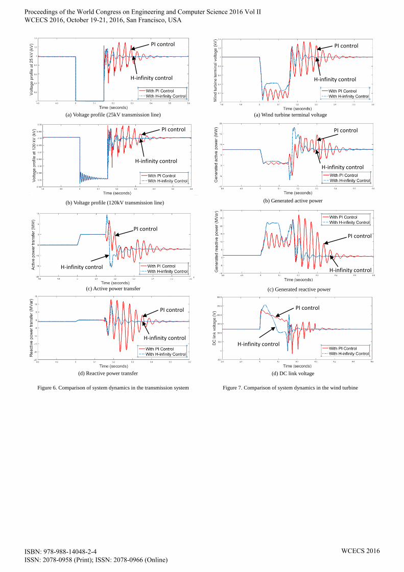
(a) Voltage profile (25kV transmission line)
(c) Active power transfer
(d) Reactive power transfer
Figure 6. Comparison of system dynamics in the transmission system
(a) Wind turbine terminal voltage
(b) Generated active power
(c) Generated reactive power
Figure 7. Comparison of system dynamics in the wind turbine
(b) Voltage profile (120kV transmission line)
(d) DC link voltage
PI control
H-infinity control
PI control
H-infinity control
PI control
H-infinity control
PI control
H-infinity control
PI control
H-infinity control
PI control
H-infinity control
PI control
H-infinity control
PI control
H-infinity control
Proceedings of the World Congress on Engineering and Computer Science 2016 Vol II WCECS 2016, October 19-21, 2016, San Francisco, USA
ISBN: 978-988-14048-2-4 ISSN: 2078-0958 (Print); ISSN: 2078-0966 (Online)
WCECS 2016