Embed Size (px)
Citation preview
1
Abstract— Toilet flushing is the single highest use of water in
the average home. Toilets make up about 31% of overall household water consumption. Most WC bowls used in western countries are fitted with a water trap that uses a large amount of water for preventing odor from the sewers from traveling back into the room. The current market standards differ between 6/3 liters and 4,5/3 liters using this system, and latest developments have proven that the water flush cannot be reduced further. Because of this, finding a way to replace the current water trap with another mechanical solution is the main objective for this project.
The basis of this project is to develop a mechanical flapper that would work automatically with the help of springs that would allow for a significant flush water reduction. Keywords—Flapper, odor prevention, toilets, water consumption
I. INTRODUCTION he company Roca first began its business creating cast iron radiators for domestic heating, but is now well known for its china bathroom appliances which it began
production of in 1936. Today, Roca’s commercial network spreads over 135 countries supplied by its 76 production plants and more than 20.000 employees worldwide. Roca’s original and still principal factory is located in Gavà, and now collaborates with the Escola Politenica Superior d’Enginyeria de Vilanova I la Geltru (EPSEVG) and its European Project Semester (EPS) and International Design Project Semester (IDPS) programs. Collaboration with the EPS program gives the company the opportunity to develop projects related to water culture from a multidisciplinary perspective and profit from the academic supervision offered by the School of Engineering. The project team includes two Mechanical Engineers: Marcel Carrera and Sierra Lunsford and two Industrial designers: John Egan and Valeria Flores. Project manager from EPSEVG, Nora Martinez, and the Roca Innovation Lab project manager, Jordi Corral, supervises the team. Most WC bowls used in western countries are fitted with a water trap that prevents odor from the sewers from traveling
Manuscript received June 10, 2016. This work was supported in part by
Roca in Gavà Barcelona and the Universitat Politècnica de Catalunya, BarcelonaTech, Escola Poltècnica Superior d’Enginyeria de Vilanova I la Geltru. It is part of the European Project Semester 2016 which took place from the 10th February to the 23rd of June
Marcel Carrera, Mechanical Engineering, Escola Poltècnica Superior d’Enginyeria de Vilanova I la Geltru, Spain. ([email protected])
John Egan, Creative design, I.T Sligo Ireland, Ireland ([email protected])
Sierra Lunsford, Mechanical Engineering, Michigan Technological University, USA. ([email protected])
Valeria Flores, Industrial Design, Tecnológico de Monterrey, México. ([email protected])
back into the room. This water trap system for the standard toilet was developed in 1775, and there has been little modification to the functionality of the method since. Because the water trap system has been so effective, there has been no urgent need to change it. However, Roca has always been attentive to the changes in society related to water culture since it began its production of bathroom appliances, and latest developments have proven that the water flush cannot be reduced further. The current market standards differ between 6/3 liters and 4,5/3 liters using this system. Therefore, this year the company has assigned the EPS team the project of designing a new system for a standard toilet to reduce the water consumption of the flush. The main objective for this project is to replace the water trap in the toilet with a mechanical trap system that:
• Meets the same functions as the current water trap. • Provides an equally robust back odor prevention by
keeping an equivalent water seal. • Allows for a significant flush water reduction. • Can be installed in developing countries as well.
II. PREVIOUS RESEARCH Before starting to develop concepts and solutions, several
previous research had to be done for further understanding on the context the team was working on.
A. Toilets water consumptions Most of the water usage at home is done indoors.
Approximately 93% of the overall water usage at home includes: toilets, personal washing, clothes watching and kitchen. Just toilets use about 30% of the total water used in a household. Since 1994 every toilet manufacture uses a maximum of 1.6 gallons per flush.[10] Estimates may vary, but each person uses about 80-100 gallons of water per day. Because of this is important to try to reduce the amount of water toilets use even further.
B. How toilets work? The working of a current toilet is very simple. There is
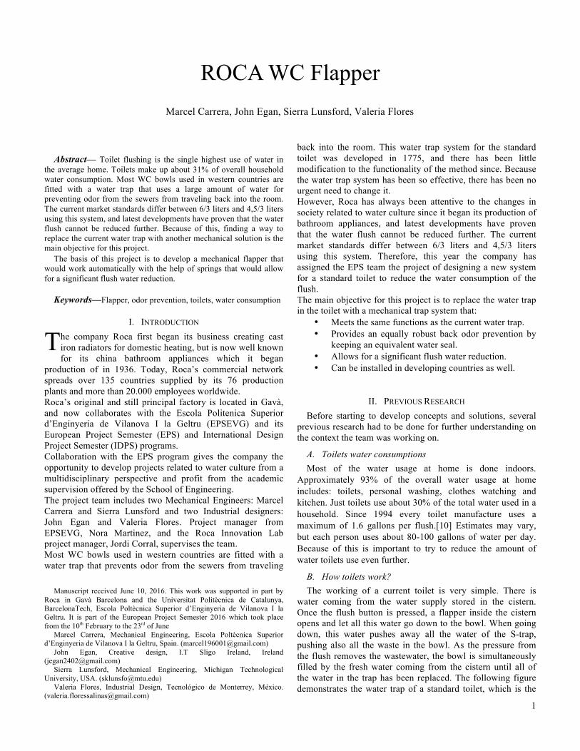
water coming from the water supply stored in the cistern. Once the flush button is pressed, a flapper inside the cistern opens and let all this water go down to the bowl. When going down, this water pushes away all the water of the S-trap, pushing also all the waste in the bowl. As the pressure from the flush removes the wastewater, the bowl is simultaneously filled by the fresh water coming from the cistern until all of the water in the trap has been replaced. The following figure demonstrates the water trap of a standard toilet, which is the
ROCA WC Flapper Marcel Carrera, John Egan, Sierra Lunsford, Valeria Flores
T
2
area that the team must re-design. The amount of water shown in blue Is 2.5 L and is what functions as the current seal, which is the one being replaced with a mechanical system.
Fig. 1 Water trap of a standard toilet.
C. Water traps A toilet bowl is a reservoir of water with an open bowl
above and an internal S-trap below. The trap way is formed into the china fixture and bends either toward the front or back of the bowl. [11] All waste gives off gas and when water is flushed the toilet, the water disappears somewhere outside the main drainage. All of this gas then tries to escape back up the pipes or through any other aperture it can get through. The main objective of the water trap is to prevent this gases coming back. The water sits in the S bend where it forms a blockage for gases and odors trying to get back in the room. The water will sit just below the level of the outlet bend until more fresh water is introduced from the incoming pipe.
III. CONCEPTS DEVELOPMENT The stage of concept development consists in generating
different methods for each function. To aid in their brainstorming and formation of initial concepts the team tried to break down the system into separate generalized functions that the new design would have to incorporate no matter what the final solution would be.
A. First Round brainstorming The first round of brainstorming concepts was focused on
different ways in which the problem could be solved, not only focusing con mechanical flapper but trying to find other feasible solutions. The team had the liberty to explore into different directions and analysis the effectiveness of each one.
1) Flexible Material The idea was to use some sort of rubber or formation plastic which would use a suction force from the flush of the toilet to seal shut. The seal would open and close in a motion similar to that of an accordion, and would seal about either the vertical or horizontal axis.
2) Gate This concept came from the idea of creating a gate that could separate the bowl from the S-trap, trying to stop all the waste and extra water until the flush button is activated. The main purpose of this gate in the concept is to work similar as the airplane toilets. The concept was thought of working as a both, as flapper and as an odor seal, for stop using water.
3) Piston Concept As previously stated the new toilet needs a mechanical trap system that seals off the pipes under the toilet bowl while still
maintaining a certain level of water in the bowl. While researching existing methods of various water systems the team was inspired by bathtubs that utilize a trip lever drain such as the one displayed in Figure
4) Flapper It’s design is essentially creating a piece of material that separates the narrow end of a toilet bowl to the S tube/sewer piping. The flapper mechanism would replace the water currently used in the S tube piping as the trap for sealing in odors. Therefore saving one half to two liters of water. A little water would still be needed in the bowl, on top of the flapper to help with cleanliness and waste removal.
B. Second round Brainstorming After it was decided a flapper would be used for the solution to the project, the company provided the team with various patents of pre-existing designs that use a flapper as the mechanical trap system inside a toilet. Using ideas pulled from the patent analysis in conjunction with their own ideas, the team created a new round of brainstorming focusing solely on different functions or aspects of the flapper design including: how it will open and close, how it will lock, and how it could be attached.
1) Tension and Compression Springs This concept incorporates the force of a spring to open and close the flapper. This design would be fairly easy to produce once the perfect spring was found, but it is predicted the team may encounter some difficulty finding a spring that both has enough strength to push or pull the flapper back into the closed position and hold it there while still being flexible enough to open with simply the force of the flush.
2) Counterweight The plan for this design would be that the flapper remains closed until the user flushes the toilet, and the flapper would then open strictly with the force of the flush. The general idea of using a counterweight appeared to be the simplest solution during this round of concept evaluation. It does not have the concerns of fatigue or durability that the spring design has, and would close the flapper in a more controlled motion.
3) Window method The most appealing feature of this design is the amount of control and fluidity of the movement of the opening and closing of the drawer or window. The opening/closing mechanism has a hinge arrangement with two linked arms pivoting from a runner, which may be attached to the window frame. One or both of the pivoting arms is mounted to the runner on a slider, which is movable along the runner in relation to the pivot mounting of the other arm. The mechanism is operable by way of a cable or cord, which has portions wound around a spool, which is rotatable by the user.
4) Hook concepts This design would require the user to pull a flush valve instead of pushing a button, as can be found in some older models of Roca toilets. This method appears to be a very simple solution
3
to open and close the flapper in a secure manner. However the pull valve is not as visually appealing as the current push button, and it would be harder to incorporate a dual flush system using this design.
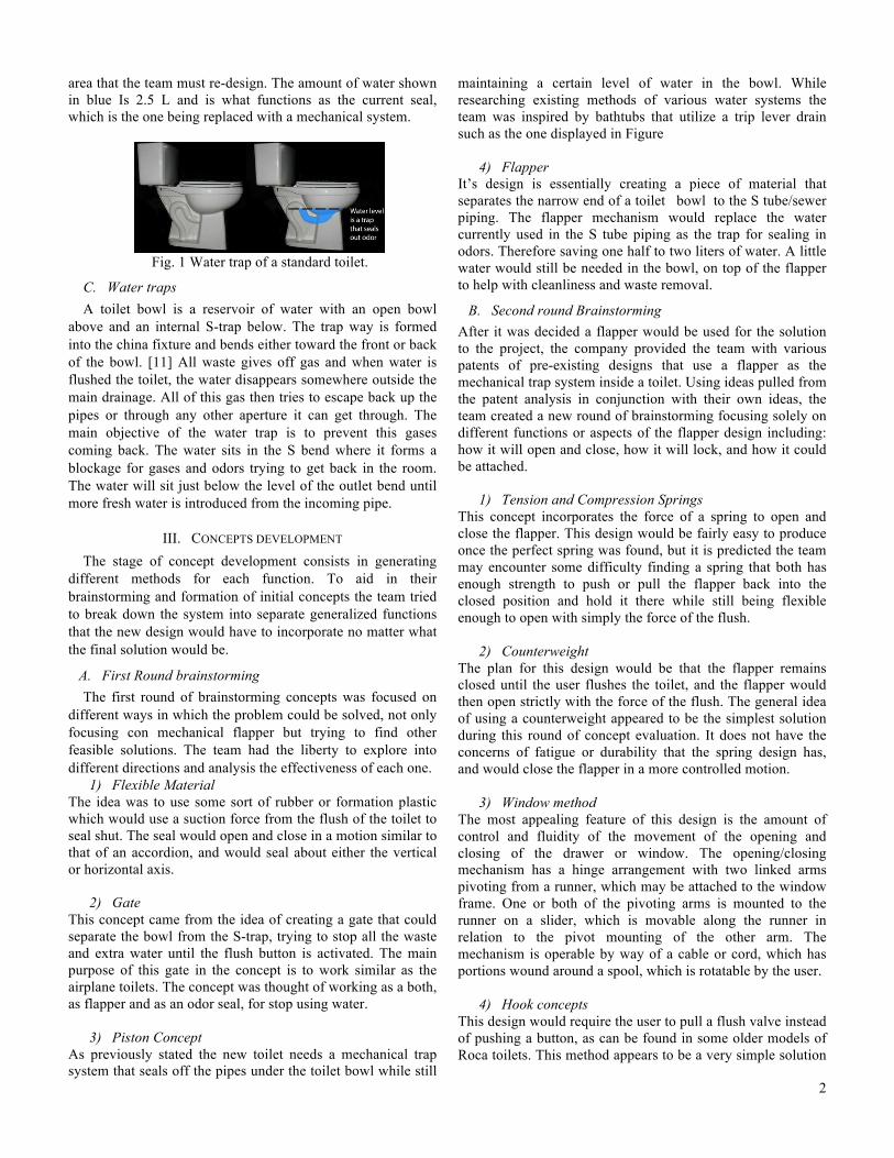
IV. FINAL CONCEPT For the final concept, a merge of all concepts was designed since all of them had some advantage that could be used for a better result. The final concept is a combination of forces, forces that would help to maintain the flapper closed, to open and to go back to its initial position. A counterweight and a traction spring will be used to maintain the flapper closed and balance when it is only holding clean water with no waste on it. For the flapper to open, extra weight needs to be deposit but cannot open until the user flushes. The flapper will open until the extra weight of the waste and water flush are deposit on the bowl (step 1). This force will make the flapper to loose balance and will open since the force on the opposite side of the counterweight is greater. For the flapper to open at an acceptable angle for the waste and water to start circulating through the pipes, the flapper need to open to 25º and the counterweight need to be exactly at the top of the pivot point (step 2). For the flapper to open to its maximum angle (55º), the counterweight should pass the pivot point (step 3) and it’s force and the inertia forces would maintain the flapper open for a few seconds. After this the weigh on the flapper will be reduces and he counterweight would be able to close the flapper and maintain it closes as its starting position. These steps are illustrates on Figure 1.
Figure 1. Counterweight Steps
Some of the major problems faced, was that the weight the counterweight needed to maintain the flapper closed and balance was big, almost 10 kg were needed, according to calculations and approximations with data given by the company about the minimum amount of water needed in the toilet and waste weight. So the teamed played with different materials with different densities for reducing as much as possible the size of the counterweight. Also since the main objective at this point was to reduce the size, an extra force was added for making it easier for the counterweight to bring the flapper back, so here is were the springs form previous concepts take action. A compression spring was added to compensate that force that the counterweight was doing. Figure 2 illustrates were the spring is placed and how it works
in combination with the counterweight.
Figure 2. Counterweight and Spring Steps
As a result, the final design is a flapper that is closed thanks to the force of the counterweight and the traction spring that are in balance with the weight of the water in the bowl (.5L), and when extra weight, including human waste and others (the team calculated that the maximum weight the flapper needed to hold was 1.5 grams, including water and waste), is introduced into the bowl the counterweight and spring are still heavier so the flapper is still closed. After the user flushes, the flapper will open 25º and once the counterweight passes the pivot point it would open to its maximum angle of 55º in which all waste and water will be able to evacuate. Finally the flapper will return slowly thanks to the force of the spring and the counterweight. On the following section, a full explanation of all the calculations and formulas needed for the flapper to work will be explained.
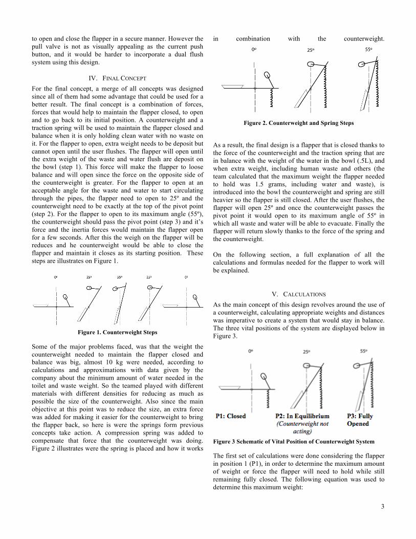
V. CALCULATIONS As the main concept of this design revolves around the use of a counterweight, calculating appropriate weights and distances was imperative to create a system that would stay in balance. The three vital positions of the system are displayed below in Figure 3.
Figure 3 Schematic of Vital Position of Counterweight System
The first set of calculations were done considering the flapper in position 1 (P1), in order to determine the maximum amount of weight or force the flapper will need to hold while still remaining fully closed. The following equation was used to determine this maximum weight:
4
Equation 1
Wtotal = Wwater + Wsolid + Wurine + Wflapper Where Wtotal is the total weight acting on the flapper, Wwater, is the weight of the water in the bowl, Wsolid is the maximum weight of solid waste that could occur, Wurine is the maximum weight of urine that could occur, and Wflapper is the weight of the flapper. Table 1, shown below, displays the given values that were provided by the company based on previous research.
Table 1. Provided Values
hw, height of water in flapper/bowl
30 mm
Wsolid, maximum weight of solid waste
500 grams
Vurine, maximum volume of urine
250 mL
Vflush, volume of flush water 1.5 – 2 Liters
Table 2. Densities of Related Materials
Using the data from Table 4 and 5 and Equations 2 and 3 all variables from Equation 6.1 could be calculated. Equation relates density (𝜌), mass (m), and volume (V), and Equation 6.3 related weight (W) and mass (m) where g is the constant acceleration due to gravity of 9.81 m/s. The results are shown below in Table 3.
Equation 2
𝜌 =𝑚𝑉
Equation 3
W = mg
Table 3. Calculated Values of Weight acting on Flapper
Wwater, Weight of water in bowl
454 g -> 4.45 N
Wurine, Weight of urine 257.5 g -> 2.52 N Wsolid, Weight of solid 500 g -> 4.91 N Wflapper, Weight of flapper 235.46 g -> 2.22 N WTotal, Total max weight of closed flapper
1446.96 g -> 14.19 N
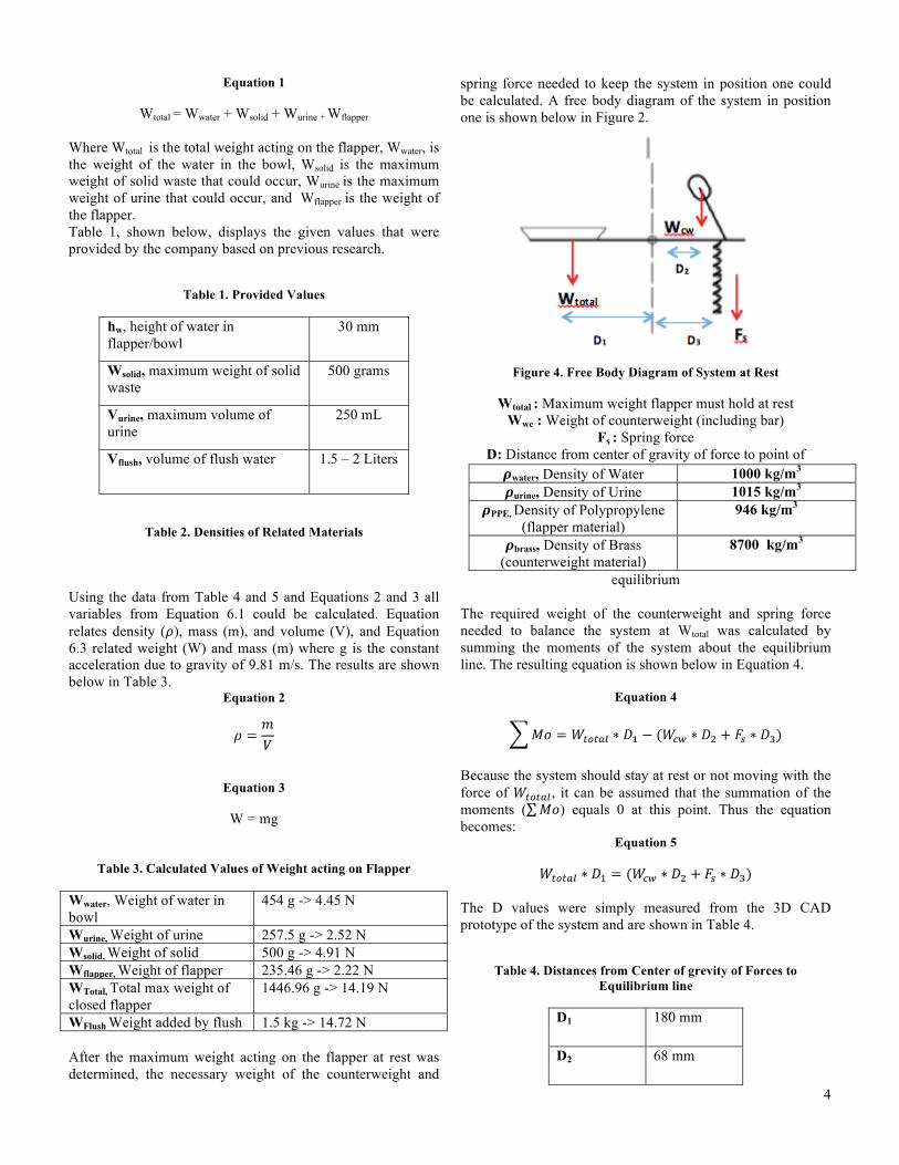
WFlush Weight added by flush 1.5 kg -> 14.72 N After the maximum weight acting on the flapper at rest was determined, the necessary weight of the counterweight and
spring force needed to keep the system in position one could be calculated. A free body diagram of the system in position one is shown below in Figure 2.
Figure 4. Free Body Diagram of System at Rest
Wtotal : Maximum weight flapper must hold at rest Wwc : Weight of counterweight (including bar)
Fs : Spring force D: Distance from center of gravity of force to point of
equilibrium The required weight of the counterweight and spring force needed to balance the system at Wtotal was calculated by summing the moments of the system about the equilibrium line. The resulting equation is shown below in Equation 4.
Equation 4
𝑀𝑜 = 𝑊!"!#$ ∗ 𝐷! − (𝑊!" ∗ 𝐷! + 𝐹! ∗ 𝐷!)
Because the system should stay at rest or not moving with the force of 𝑊!"!#$, it can be assumed that the summation of the moments ( 𝑀𝑜) equals 0 at this point. Thus the equation becomes:
Equation 5
𝑊!"!#$ ∗ 𝐷! = (𝑊!" ∗ 𝐷! + 𝐹! ∗ 𝐷!) The D values were simply measured from the 3D CAD prototype of the system and are shown in Table 4.
Table 4. Distances from Center of grevity of Forces to Equilibrium line
D1 180 mm
D2 68 mm
𝝆water, Density of Water 1000 kg/m3 𝝆urine, Density of Urine 1015 kg/m3
𝝆PPE, Density of Polypropylene (flapper material)
946 kg/m3
𝝆brass, Density of Brass (counterweight material)
8700 kg/m3

5
D3 100 mm
Due to size limitations there was a maximum volume that the cylinder could have to enable the system to function properly within the attachment box. After testing various sizes and shapes of counterweights within the CAD design, it was decided the most functional form for the counterweight would be two smaller cylinders with a total volume of 91.95 cm3 each one. Knowing the material of the counterweight and therefore the density of the counterweight, Equations 2 and 3 were then used to find the desired weight of the counterweight. Once Wcw was calculated, it could be plugged into Equation 5 along with the values in Table 7 to solve for Fs, the necessary spring force. The calculated values for these balancing forces are shown below in Table 5.
Table 5. Final Values for Forces Acting to Balance System
Wcw, Weight of Counterweight
1.6 kg
Fs, Spring Force 1.072 N
Equation 6
𝐹 = 𝑘𝑥 With the Fs calculated, we use the equation 6 to find the approximated characteristics of the spring, constant (k) and the distance displaced by the spring. Using an initial displacement of 15 mm, we find that the k of our spring should be 0.0714 N/mm
Table 6. Spring Characteristics
k 0.0714 N/mm
x 15 mm
After all the calculations of the rest position were done, it is necessary to check if the spring chosen is able to turn back the flapper to the rest position
Figure 5. Free Body Diagram of System at 55º
Once the new distances are known (table 8), they can be plugged into the the Equation 5, taking in consideration that
now the weight of the counterweight (Wcw) is acting in the other direction, working now against the spring.
Table 7. Distances from Center of Gravity of Forces to Equilibrium line at 55º
D4 103.24 mm
D5 13.4 mm
D6 57.36 mm
As a result, we come up with a spring force of 2.534 N. So, as we expected, the maximum force of the spring remains in reasonable values.
VI. MATERIALS For this project, choosing the right material is a crucial part. According to Michael Ashby in Material Selection in Mechanical Design, the design of engineering components involves three interrelated problems: (i) selecting materials, (ii) specify a shape and (iii) choosing a manufacturing process. [4] In this case, for guarantee better results on the manufacture of the flapper, the material that was going to be chosen needed to accomplished the following characteristics:
• Durable • Resistant to chemical attacks such as in-tank bowl
cleaners and most important: urine chemicals • The material should maximize the leak free life of
the flapper • Smooth and even surfaces • Impact of environmental factors such as heat, cold,
expansion, contraction, corrosion, pH and bacteria levels.
• Low cost material • Low maintenance
The material that is chosen can’t have any warping, swelling, blistering to high temperature nor crack under any circumstances. According to the previous needs and considerations, the team started to look for possible materials in which metals and plastic were the one that could meet the conditions established. Taking in consideration the lists of advantages and disadvantages and discussing with the company, the team decided that plastics should be better for manufacturing the flapper and most of its components of the design since the advantages were more than fabricating with metals, and also plastics helped to fulfill the needs and characteristics that the team needed and listed in the beginning of this section.
6
A. Plastics Plastic is made from hydrocarbons found in oil and natural gas. It’s created when small molecules, called monomers, are bonded together into chains called polymers. Different monomers, when bonded together, create different kinds of plastic; some are soft and pliable, some hard and durable, and others somewhere in between. Because of this, further investigation among the different kinds of plastics and their properties was needed for a better understanding on how each material behaves and which one would fit better to the project’s needs. [6] Since the flapper has to be durable and resistant since it is planned to last as long as possible with the minimum maintenance, have a good chemical resistance for preventing any kind of material cracking or deformation thanks to in-tanks bowl cleaners or urine acids, and resistant to environmental factors such as heat, cold, corrosion, pH, etc, Also the material chosen has to avoid any kind of warping and swelling. The team reduced the options into choosing between thermoset plastics and thermoplastics, since are the ones that better fit to these characteristics. For the flapper, the team decided that according to the material properties, using polypropylene as the main material would guarantee a better performance and a better life cycle of the product. Some of the most important properties of polypropylene that the flapper needs to have are: rigid material, good chemical resistance, though, good fatigue resistance, integral hinge property and a good heat resistance. Another important factors are that PP does not present stress-cracking problems, offers an excellent chemical resistance at higher temperatures, lower density, higher rigidity and hardness compared to those of Polyethylene and also this material offers the option that additives can be applied in order to protect the polymer during processing and to enhance end-use performance. [9] After analyzing all the characteristics of the plastic and the ones that the flapper needed to have, the team concluded that polypropylene would be the primary material used in the final design. Also polypropylene would be used in other components of the design such as the box and holders. For protecting the whole mechanism and for adapting it to the toilet, a box was designed which also needed to have the same characteristics of durability, strength and resistance as the flapper. Since the box is the one that is going to be in constant contact with the user and is the one that will give the first impression of the product, the team decided to use PP as well, not only because of its properties, but also because of the aesthetics that plastic can give.
B. Metals The counterweight will play a very important role since is the one would maintain the flapper closed, would open the flapper when flushed, and would help close the flapper back again to
its initial position. The flapper need to hold closed about 1.5 liters of water and some extra weight from human waste, and any extra weight, in this case, of the flushing water, will open the flapper since it would weight more than the counterweight. After calculations, the counterweight needed to be from 1 to 3 kilograms. Because of this, the material for the counterweight needs to have a big density for having the greater weight in a smaller size. Because of this, different kinds of metals were analyzed since there are the ones with the highest densities.
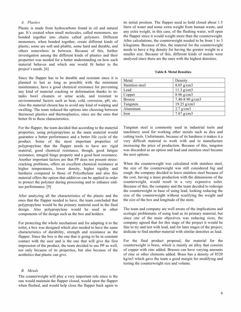
Table 8. Metal Densities
Metal Density Stainless steel 8.05 g/cm3 Lead 11.3 g/cm3 Copper 8.96 g/cm3 Bronze 7.40-8.90 g/cm3 Tungsten 19.25 g/cm3 Aluminum 2.7 g/cm3 Iron 7.87 g/cm3
Tungsten steel is commonly used in industrial tools and machinery used for working other metals such as dies and cutting tools. Unfortunate, because of its hardness it makes it a very difficult material to work with and to manufacture increasing the price of production. Because of this, tungsten was discarded as an option and lead and stainless steel became the next options. When the counterweight was calculated with stainless steel, the size of the counterweight was still considered big and rough. the company decided to leave stainless steel because of the cost, having a mass production with the dimensions of the counterweight, would result in a very expensive toilet. Because of this, the company and the team decided to redesign the counterweight in base of using lead, looking reducing the size of the counterweight without scarifying the weight and the size of the box and longitude of the stem. The team and company are well aware of the implications and ecologic problematic of using lead as its primary material, but since one of the main objectives was reducing sizes, the company agreed that for this stage of the project it would be fine to try and test with lead, and for later stages of the project, dedicate to find another material with similar densities as lead. For the final product proposal, the material for the counterweight is brass, which is mainly an alloy that consists of copper with zinc added. Brasses can have varying amounts of zinc or other elements added. Brass has a density of 8520 kg/m3 which gave the team a good margin for modifying and testing the counterweight size and volume.

7
VII. PROTOTYPE
A. First stage prototype A prototype is an early sample, model, or release of a product built to test a concept or process or to act as a thing to be replicated or learned from. [8] For the first stage, the whole concept was going to be tested, the team wanted to prove if the counterweight theory of passing the pivot point will be enough for opening and closing the flapper and most important, how strong the spring needed to be for helping the counterweight to act. The first rough prototype was barely similar in shape to the original design, but since the function was the one that was being tested, the team focused the minimum in appearance for this stage. Pictures of the prototype are shown below. From this stage, the results were favorable. In theory, a counterweight of 1.5 kg with a certain unknown traction spring would maintain the flapper on balance with water and human waste.
B. Second Stage prototype For this stage, the company provided an actual toilet bowl for the team to adapt the mechanical system of the flapper to a more realistic scenario. As the original design, the S-trap was removed form the vitro china toilet as shown in Figure 30. The main objective of this stage was to test shapes and forms. Since the functionality of the mechanism had been testes in previous stages, now the team faced the challenge of making a functional prototype with the mechanism and as close as possible to the final and original design in terms of appearance of the product. For making it more realistic, the flapper was 3D printed and the material of the counterweight was changed into cast iron for a similar form as the final design.
Figure 4. Vitro China Toilet with no S-Trap
The main problems faced during this stage were fitting the whole mechanisms inside the toilet. Trying to find new ways to reduce sizes, the team started playing with the positions and shape of the counterweight to find if it could work with less weight. As a result, the team managed to reduce the size of the counterweight from 1.5 grams to 1.34 grams, reducing significantly the size. Also for reducing the size, the team introduced some lead bass drops pieces used in fishing just like figure 5 shows. With this the team succeed to have the
effect and function of the counterweight with a considerable size that fit perfectly in the toilet.
Figure 5. Lead Bass Drops
Other problem faced was the shape of the flapper. The team discovered that for the mechanism to work, the flapper should hold the water and not let it escape, since if this happens, the weight needed to open would never be reached. Since the flapper had the shape shown in figure 6, water easily escape from the front part since it didn’t have the proper seal and proper fitting to the toilet. So the team decided to try sealing it and change the shape of the flapper for a better fit. The final shape of the flapper is shown in figure 7.
Figure 6. Initial Flapper Concept
8
Figure 7. Final Flapper
With this final shape the team prevents the escape of water and allows the flapper to hold the water until the necessary weight is reached for open the flapper. Also the shape of the flapper avoids that any waste, including human waste and paper, stick in the flapper.
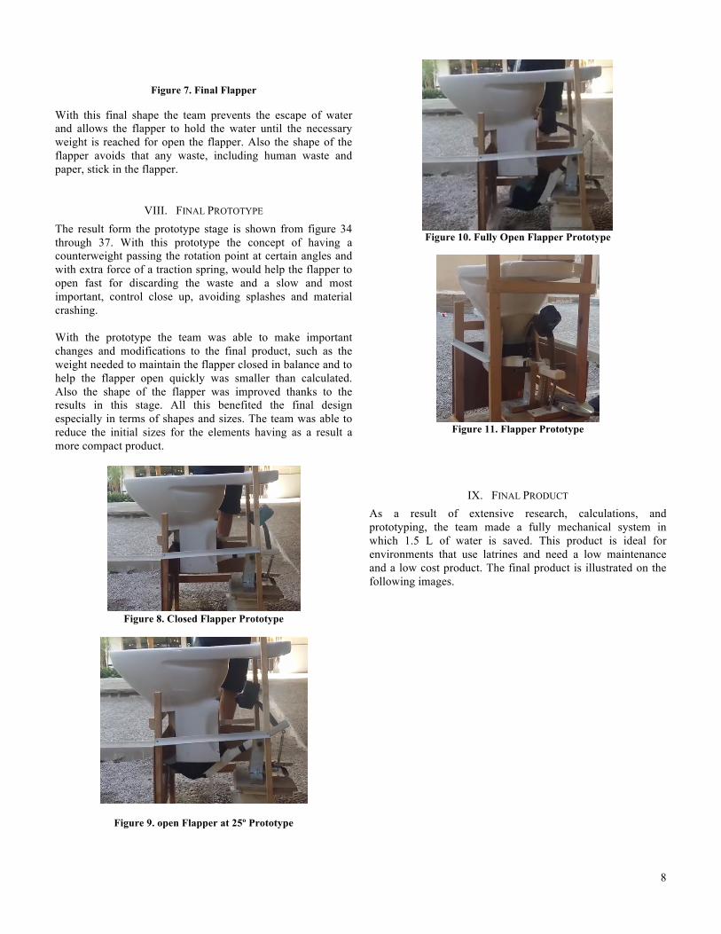
VIII. FINAL PROTOTYPE The result form the prototype stage is shown from figure 34 through 37. With this prototype the concept of having a counterweight passing the rotation point at certain angles and with extra force of a traction spring, would help the flapper to open fast for discarding the waste and a slow and most important, control close up, avoiding splashes and material crashing. With the prototype the team was able to make important changes and modifications to the final product, such as the weight needed to maintain the flapper closed in balance and to help the flapper open quickly was smaller than calculated. Also the shape of the flapper was improved thanks to the results in this stage. All this benefited the final design especially in terms of shapes and sizes. The team was able to reduce the initial sizes for the elements having as a result a more compact product.
Figure 8. Closed Flapper Prototype
Figure 9. open Flapper at 25º Prototype
Figure 10. Fully Open Flapper Prototype
Figure 11. Flapper Prototype
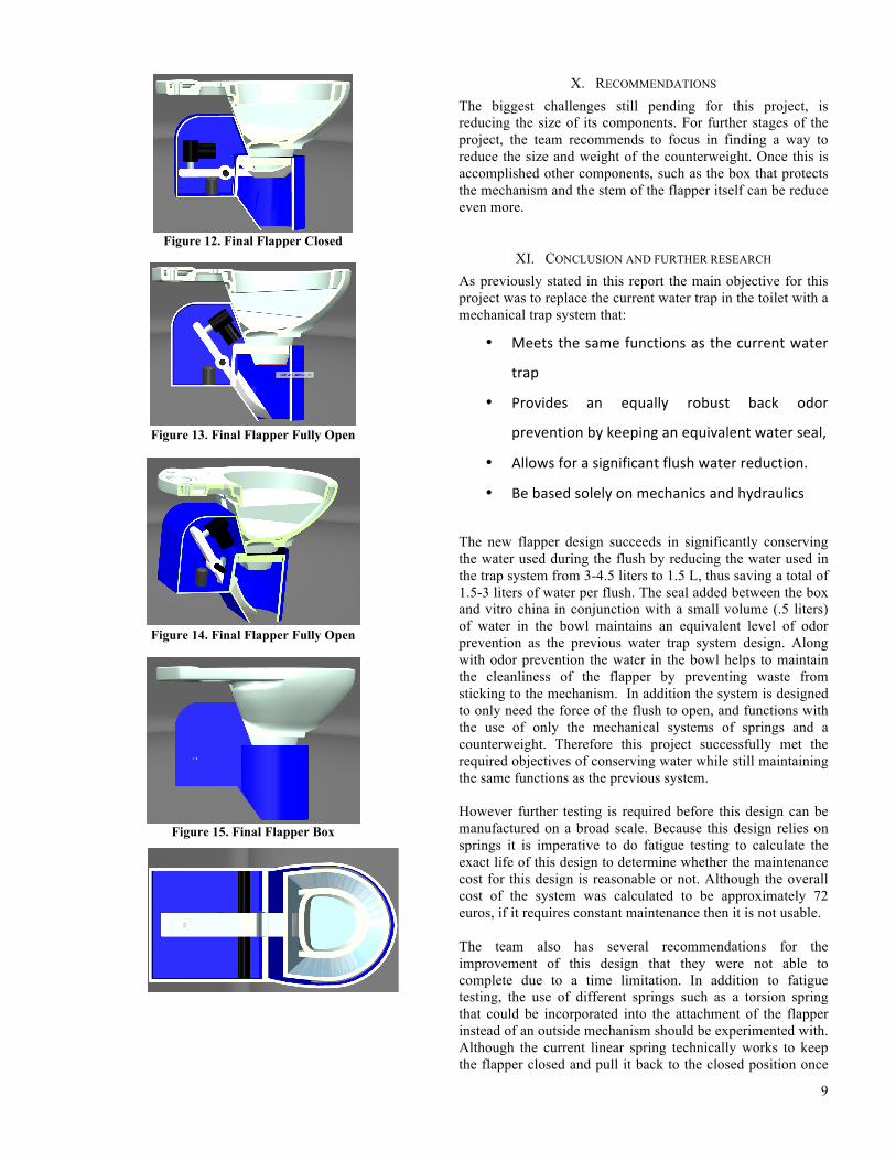
IX. FINAL PRODUCT As a result of extensive research, calculations, and prototyping, the team made a fully mechanical system in which 1.5 L of water is saved. This product is ideal for environments that use latrines and need a low maintenance and a low cost product. The final product is illustrated on the following images.
9
Figure 12. Final Flapper Closed
Figure 13. Final Flapper Fully Open
Figure 14. Final Flapper Fully Open
Figure 15. Final Flapper Box
X. RECOMMENDATIONS The biggest challenges still pending for this project, is reducing the size of its components. For further stages of the project, the team recommends to focus in finding a way to reduce the size and weight of the counterweight. Once this is accomplished other components, such as the box that protects the mechanism and the stem of the flapper itself can be reduce even more.
XI. CONCLUSION AND FURTHER RESEARCH As previously stated in this report the main objective for this project was to replace the current water trap in the toilet with a mechanical trap system that:
• Meets the same functions as the current water
trap
• Provides an equally robust back odor
prevention by keeping an equivalent water seal,
• Allows for a significant flush water reduction.
• Be based solely on mechanics and hydraulics
The new flapper design succeeds in significantly conserving the water used during the flush by reducing the water used in the trap system from 3-4.5 liters to 1.5 L, thus saving a total of 1.5-3 liters of water per flush. The seal added between the box and vitro china in conjunction with a small volume (.5 liters) of water in the bowl maintains an equivalent level of odor prevention as the previous water trap system design. Along with odor prevention the water in the bowl helps to maintain the cleanliness of the flapper by preventing waste from sticking to the mechanism. In addition the system is designed to only need the force of the flush to open, and functions with the use of only the mechanical systems of springs and a counterweight. Therefore this project successfully met the required objectives of conserving water while still maintaining the same functions as the previous system. However further testing is required before this design can be manufactured on a broad scale. Because this design relies on springs it is imperative to do fatigue testing to calculate the exact life of this design to determine whether the maintenance cost for this design is reasonable or not. Although the overall cost of the system was calculated to be approximately 72 euros, if it requires constant maintenance then it is not usable. The team also has several recommendations for the improvement of this design that they were not able to complete due to a time limitation. In addition to fatigue testing, the use of different springs such as a torsion spring that could be incorporated into the attachment of the flapper instead of an outside mechanism should be experimented with. Although the current linear spring technically works to keep the flapper closed and pull it back to the closed position once

10
it is opened, the team is not convinced it is the most efficient solution at this time. Furthermore, a bumper is currently being used to soften the return of the flapper and prevent it from having a hard impact against the vitro china. However, further investigation should be done to determine if there is a method that will produce two motions of the flapper such that there is a high resistance against the opening of the flapper until an angle of 25 degrees and then a low resistance after 25 degrees, and the opposite effect upon closing. Having a mechanism that would work this way throughout the motion of the flapper, instead of just stopping it at the end of the desired motion, would allow for a smoother close of the flapper which in turn would reduce fatigue over time and prevent the flapper from creating splashes upon its return. Finally, the greatest challenge still pending for this project, is reducing the size of its components. Originally the team desired to make this product applicable both for latrines and the average home, but with the current design it is only suitable for latrines. The total height of the toilet with this design is 472 mm while the toilet in the average home currently stands at a maximum of 410 mm; for a latrine part of the box can be placed underground but for the house it is not reasonable. Also the flapper currently opens in the opposite direction from the way the current toilet pipes run into the sewage system, and due to size limitations it is not possible to rotate it to the other side. In conclusion, although the design of the new system successfully meets the objectives and is simple enough to be industrialized the team recommends making the improvements mentioned above before actually manufacturing this product.
XII. ACKNOWLEDGMENTS After this four moth of work, the team would like to express our appreciation to all the parties involved in the WC Flapper project: First of all, the team wants to thanks to UPC Supervisor Nora Martinez for her continuous support and constant feedback during the whole process. Her constant advises, guidance and specially her energy helped the team to get the best results. Beside the university supervisor, the team would also like to express their gratitude to the company Roca for defining the project in which bot, designers and engineers, could apply their knowledge and learn even more about engineering and design issues. From Roca, the team would specially thanks supervisor Jordi Corral, who even with his important agenda, he always found time to be at every meeting and giving very important feedbacks and recommendations to the team. Also, for giving the team all the tools and resources necessary for the team to accomplish their objectives. Thanks to Universitat Politècnica de Catalunya, Escola Politècnica Superior d`Enginyeria de Vilanova i la Geltrù for performing this programs in which they give their students the
opportunity to get along with students from different nationalities and also for the opportunity of working in a real project with real clients and companies. Especial thanks to the university supervisors, especially Neus Salleras, for administrating and coordinating the EPS/IDPS project. Last but not least the team would like to thanks their universities at home for allowing this kind of experiences abroad: Tecnologíco de Monterrey, Mexico. Institute of Technology Sligo, Ireland. Michigan Techonologial University, USA. Escola Politècnica Superior d`Enginyeria de Vilanova i la Geltrù, Sapin.
REFERENCES
[1]R. Kivi, "How Does the Bathroom on a Bus Work? | eHow", eHow, 2016. [Online]. Available: http://www.ehow.com/how-does_4743000_bathroom-bus-work.html. [Accessed: 27- Apr- 2016]. [2]"LOW OR NO WATER USE LATRINE PANS, LATRINE PAN ASSEMBLIES, LATRINES AND RELATED METHODS - AS IP HOLDCO, L.L.C.", Sumobrain.com, 2016. [Online]. Available: http://www.sumobrain.com/patents/wipo/Low-no-water-use-latrine/WO2015109301A1.html. [Accessed: 27- Apr- 2016].
[3]"Hybrid Toilet System", NSW Government. HEALTH, 2016. [Online]. Available: http://www.health.nsw.gov.au/environment/domesticwastewater/accreditations/sc020.pdf. [Accessed: 27- Apr- 2016]. [4] M. Ashby, Material Selection in Mechanical Design. [Online]. Available: http://homepages.cae.wisc.edu/~me349/lecture_notes/material_selection.pdf. Accessed: Jun. 15, 2016. [5] T. P. Company, "Plastic vs. Metal fabrication - advantages and disadvantages," 2016. [Online]. Available: http://www.thomasnet.com/articles/custom-manufacturing-fabricating/plastic-fab-metal-fab. Accessed: Jun. 15, 2016. [6] BBC, "GCSE Bitesize: Plastics," in BBC, 2006. [Online]. Available: http://www.bbc.co.uk/schools/gcsebitesize/design/resistantmaterials/materialsmaterialsrev3.shtml. Accessed: Jun. 15, 2016. [7] CustomPartNet, "Injection molding process, defects, plastic," 2009. [Online]. Available: http://www.custompartnet.com/wu/InjectionMolding. Accessed: Jun. 15, 2016. [8] B. P. F. 2016, "Related categories," 2016. [Online]. Available: http://www.bpf.co.uk/plastipedia/polymers/PP.aspx. Accessed: Jun. 15, 2016. [52] "Prototype," in Wikipedia, Wikimedia Foundation, 2016. [Online]. Available: https://en.wikipedia.org/wiki/Prototype. Accessed: Jun. 15, 2016. [9] "Plastic pros and cons," in Lifestyle, alive, 2008. [Online]. Available: http://www.alive.com/lifestyle/plastic-pros-and-cons/#sthash.clSX59Hc.dpuf. Accessed: Jun. 15, 2016. [10] D. Media, "How many gallons of water does it take to flush a toilet?,". [Online]. Available: http://homeguides.sfgate.com/many-gallons-water-flush-toilet-88812.html. Accessed: Jun. 15, 2016. [11] practical DIY, "Waste water traps - different types of plumbing water traps," 2006. [Online]. Available: http://www.practicaldiy.com/plumbing/waste_traps/waste_traps.php. Accessed: Jun. 15, 2016.