Embed Size (px)
Citation preview
Version Date 2/7/17
Rochester Institute of Technology
Information & Technology Services
Standards for Communications Cabling Section 27000- General
Section 27100- Cable Plant
Version Date 2/7/17 2
Proprietary Information
This document contains proprietary information and is not for use outside Rochester
Institute of Technology without prior consent. Information within this document is subject
to change without notice.
Related Documents
Document
ID Document Title Author Revision
Effective
Date
Document Change Control
Revision Date Author Section Content Changes or Additions
2014.0 11/06/14 JES 24010 Add Cat 6A
2016.0 6/7/16 JES 2410 Part Number Changes
2017.0 1/30/17 JES 27010 Part Number Review
2017.1 2/7/17 JES 27010 Drawing Changes
Content Owner
Name Department Phone Number Alternate Contact
James Shanks ITS Network Communications Team 585-475-5560 Dave Thelen
Version Date 2/7/17 3
Table of Contents
27010 BASIC COMMUNICATION REQUIREMENTS ___________________________________ 4 1 Regulations and Code Compliance __________________________________________ 4 2 RIT ITS Design Requirements for Cat 6a cabling _______________________________ 6
27100 CABLE PLANT OVERVIEW ________________________________________________ 7
27110 COMMUNICATIONS SPACES ______________________________________________ 9 1 Spaces _______________________________________________________________ 9 2 Grounding System ______________________________________________________ 9
27120 BUILDING SERVICE ENTRANCES _________________________________________ 10 1 Entrance Facilities ______________________________________________________ 10 2 Grounding System _____________________________________________________ 10
27130 INTERIOR COMMUNICATIONS PATHWAYS __________________________________ 11 1 Interior Horizontal Communication Pathways _________________________________ 11 2 Grounding System _____________________________________________________ 11
27140 EXTERIOR COMMUNICATIONS PATHWAYS _________________________________ 12 1 Exterior Communication Pathways _________________________________________ 12
27150 BACKBONE CABLING REQUIREMENTS _____________________________________ 13 1 General Interior Backbone Cable Installation _________________________________ 13 2 Copper Backbone General Specifications ____________________________________ 13 3 Copper Backbone General Splicing Specifications ______________________________ 14 4 Fiber Optic Backbone General Specifications _________________________________ 15 5 Optical Fiber Termination Hardware ________________________________________ 16 6 Coaxial Backbone General Specifications ____________________________________ 16
27160 HORIZONTAL CABLING REQUIREMENTS ___________________________________ 18 1. Work Area Outlets _____________________________________________________ 18 2. Horizontal Distribution Cable Installation ____________________________________ 18 3 Voice/Telemetry Horizontal Wiring General Specifications _______________________ 19 4 Data Wiring General Specifications _________________________________________ 20 5 Horizontal Cross Connect Installation _______________________________________ 20 6 Optical Fiber Termination Hardware ________________________________________ 20 7 Inside Backbone Cable Installation _________________________________________ 21 8 Copper Termination Hardware ____________________________________________ 21 9 Racks _______________________________________________________________ 21 10 RF Cable Distribution System _____________________________________________ 22 11 Firestop System _______________________________________________________ 22
27170 TESTING, IDENTIFICATION AND ADMINISTRATION: BACKBONE CABLING _________ 23 1 Testing and Acceptance _________________________________________________ 23 2 System Documentation _________________________________________________ 24
27170A TESTING, IDENTIFICATION, AND ADMINISTRATION: HORIZONTAL WIRING _______ 26 1. Testing and Identification/Labeling Specification for Copper Horizontal Cabling _______ 26 2 Testing and Identification/Labeling Specification for Fiber Optic Horizontal Cabling ____ 26 3 Testing and Identification/Labeling Specification for Coaxial Horizontal Cabling _______ 27 4 Documentation ________________________________________________________ 27
27190 WARRANTY _________________________________________________________ 28
Appendix 1- Typical Backbone Rack Layout ___________________________________________ 29
Appendix 2- Typical Horizontal Cable Rack Layout ______________________________________ 30
Appendix 3- Typical Combined Cable Rack Layout ______________________________________ 31
Appendix 4- Minimum Single Rack Room Layout _______________________________________ 32
Appendix 5- Minimum Dual Rack Room Layout ________________________________________ 33
Version Date 2/7/17 4
27010 BASIC COMMUNICATION REQUIREMENTS
1 Regulations and Code Compliance
1.1 All work shall be performed in a neat and professional manner.
1.2 For any information that is not covered in the following guidelines, refer to the
appropriate industry standard and organizations as listed below.
1.2.1 American National Standards Institute, Inc. (ANSI)
1.2.2 National Electrical Safety Code
1.2.3 Federal Communications Commission (FCC) Publications
1.2.4 Occupational Safety and Health Act
1.2.5 Insulated Cable Engineers Association (ICEA) Standard
1.2.6 National Fire Protection Association (NFPA)
1.2.6.1 National Electric Code (NEC): ANSI/NFPA 70
1.2.6.2 Central Station Signaling Systems: ANSI/NFPA 71
1.2.6.3 National Fire Alarm Code: ANSI/NFPA 72
1.2.6.4 Protection of Electronic Computer Data Processing Equipment:
ANSI/NFPA 75
1.2.6.5 Standard for Installation of Lighting Protection Systems:
ANSI/NFPA 780
1.2.7 National Electrical Code
1.2.8 Institute of Electrical and Electronics Engineers, Inc. (IEEE)
1.2.9 National Electrical Safety Code
1.2.10 Telecommunications Industry Association
1.2.10.1 ANSI/TIA-568-C.0 (September 2010) Generic
Telecommunications Cabling for Customer Premises
1.2.10.2 TIA-568-C.0-1 (September 2010) Generic Telecommunications
Cabling for Customer Premises-Addendum 1, Updated Reference
for Balanced Twisted-Pair Cabling
1.2.10.3 ANSI/TIA-568-C.1 (February 2009) Commercial Building
Telecommunications Cabling Standards
1.2.10.4 TIA-568-C.1-2 (November 2011) Commercial Building
Telecommunications Cabling Standard, Addendum 2 General
Updates
1.2.10.5 ANSI/TIA-568-C.2 (August 2009) Balance Twisted Pair
Communications and Components Standards
1.2.10.6 ANSI/TIA-568-C.3 (June 2008) Optical Fiber Cabling Components
Standard
1.2.10.7 ANSI/TIA-568-C.3-1 (December 2011) Optical Fiber Cabling
Component Standard- Addendum 1, Addition of OM4 Cabled
Optical Fiber and array connectors
1.2.10.8 ANSI/TIA-568-C.4 (July 2011) Broadband Coaxial Cabling
Components Standard
1.2.10.9 ANSI/TIA-942-A (August 2012) Telecommunications
Infrastructure Standard for Data Centers
1.2.10.10 TIA-569-C (May 2012) Telecommunications Pathways and Spaces
1.2.10.11 ANSI/TIA-606-B (June 2012) Administration Standard for
Telecommunications Infrastructure
1.2.10.12 TIA-607-B (September 2011) Generic Telecommunications
Grounding (Earthing) and Bonding for Customer Premises

Version Date 2/7/17 5
1.2.10.13 TIA-758-A (August 2004) Customer-Owned Outside Plant
Telecommunication Infrastructure Standard
1.2.10.14 TIA-1152 (September 2009) Requirements for Field Test
Instruments and Measurements for Balanced Twisted-Pair Cabling
1.2.10.15 ANSI/TIA-862-A (April 2011) Building Automation Systems
Cabling Standard
1.2.10.16 TIA-1005 (March 2009) Industrial Telecommunications
Infrastructure Standard for Manufacturing, Process & Refining
1.2.10.17 ANSI/TIA-1005 (March 2009) Telecommunications Infrastructure
Standard for Industrial Premises
1.2.10.18 TIA-1005-1 (March 2010) Telecommunications Infrastructure
Standard for Industrial Premises; Addendum 1 - Industrial
Pathways and Spaces
1.2.10.19 TIA-1179 (July 2010) Healthcare Facility Telecommunications
Infrastructure Standard
1.2.11 International Telecommunications Union (ITU), formally CCITT
1.2.12 BICSI
1.2.13 CSA
1.2.14 UL
1.2.15 NEMA
1.2.16 IEEE
1.3 The Contractor shall comply with the NEC and all other federal, state, local and
laws, codes and ordinances.
1.4 The Contractor shall be responsible for placement of outside plant cables within
Owner- provided pathways without splices.
1.5 For all work in manholes and cable vaults, the contractor shall be responsible for
ensuring that safe operating procedures are followed; work equipment is adequate
and personnel have received proper training. Safety equipment shall be inspected
and approved by an authorized representative of the Owner.
1.6 The Contractor shall provide the Owner with applicable warranty certification at
time of Proposal response.
1.7 The Contractor shall be responsible for measuring required cable distances and
shall not exceed appropriate cable length standards.
1.8 Product/Materials substitutions require written Owner approval at the time of
Proposal response.
1.9 The Contractor shall provide the Owner with a copy of his asbestos insurance
before work begins.
1.10 The Contractor shall provide the Owner with a copy of his Confined Spaces
permit.
1.11 The Contractor shall be courteous to all personnel on the project, including
students and other contractors.
1.12 Documentation shall be required for all categories and will be specified in the
Specific Execution sections. Generally, documentation shall be required for all
backbone pathway usage, cable pair counts, and building entrance details.
Documentation shall be required for horizontal wiring jack numbers, redlined
blueprints indicating final locations, and jack numbers. Test results as specified
under “Testing” shall be required for all categories.
1.13 Subcontractors shall not be accepted without Owner approval. Proposed use of
subcontractors shall be indicated as part of the Proposal.
Version Date 2/7/17 6
2 RIT ITS Design Requirements for Cat 6a cabling
2.1 Pathways will be accessible for future moves, adds, and changes
2.2 Pathways will be planned assuming a horizontal station cable will have
an approximate diameter of .30 inches and no more than a 40% fill ratio
2.3 1” conduit runs to station outlet locations will contain no more than 3
horizontal station cables regardless of category specification
2.4 1.25” conduit runs to station outlet locations will contain 4-8 horizontal
station cables regardless of category specification
2.5 There will be one 4” penetration for every 83 station cables passing
through a wall, ceiling, or floor.
2.6 Backbone and horizontal station cabling will not share penetrations or
installed conduit paths.
2.7 Cable hooks (J-hooks) are a suitable alternative to cable tray ONLY when
the planned capacity of the pathway system is fifty (50) cables or fewer.
2.8 Route cable tray a minimum of 5” clearance from fluorescent light
fixtures, 12” clearance from electrically operated equipment and all
wiring at 120 or more volts and 4 ft. from transformers or large motors.
2.9 Install cable tray a minimum of 3-inches above accessible ceiling T-bars.
If possible, install 6-inches above accessible ceiling T-bars.
2.10 Install cable tray with 12-inches of open space above and to one side of
the tray to allow access for installing and maintain cable.
2.11 Cable tray shall be sized and installed to meet the needs of all low
voltage cabling including room for future growth.
2.12 Wireless AP locations will be determined by RIT ITS personnel when
building floor plans in CAD become available.
Version Date 2/7/17 7
27100 CABLE PLANT OVERVIEW
1.1 Backbone Copper Cabling Products
1.1.1 RUS/REA specification PE-89 building entrance cable and/or have the Bell
standard designation AFMW
1.1.2 Circa Tel Building Entrance Terminals
1.1.2.1 Circa Tel 1900A1-100
1.1.2.2 Circa Tel 1880ECT1/NSC-XXX
1.1.2.3 Circa Tel 4B1E gas tube protector module
1.1.2.4 Circa Tel 4B1FS-240 solid-state protector modules
1.1.3 Bell standard designation ARMM type riser cable fire rated or approved
equivalent
1.1.4 Systimax XLBET main distribution frames
1.1.5 Panduit Category 5e 110 type termination hardware
1.1.5.1 P110BW100-X
1.2 Backbone/Riser Fiber Optic Cable
1.2.1 Fiber Cable
1.2.1.1 BerkTek PDP Premise Distribution Fiber Plenum Rated
1.2.1.2 Corning Cable Systems MIC OFNP or OFNR
1.2.1.3 or approved alternate for backbone applications
1.2.2 Panduit or Corning Cable Systems SC connectors
1.2.3 Fiber Optic LIU Enclosures
1.2.3.1 Panduit Opticom Rack Mount Enclosures: FRME4
1.2.3.2 Corning Cable Systems Closet Connector Housing: CCH-04U
1.3 Coaxial Cable
1.3.1 Underground backbone cable by Comm/Scope
1.3.1.1 QR86OJCASS
1.3.1.2 QR715JCASS
1.3.2 Indoor riser cable by CommScope
1.3.2.1 Plenum: 2312K
1.3.2.2 Non Plenum: QR 540 JCAR
1.4 Horizontal Wiring
1.4.1 CAT5e UTP copper for voice and data applications, plenum rated, color blue
1.4.1.1 CommScope Ultra II, Belden 1213, Belden 1701A, or BerkTek
LANmark 350
1.4.2 CAT 6 UTP copper for data applications, plenum rated, color green
1.4.2.1 CommScope UltraMedia, Belden 2413, Beldon 3613, or BerkTek
LANmark 6
1.4.3 CAT 6A UTP copper for data applications, plenum rated, color yellow
1.4.3.1 Belden 10GXS13, BerkTek LANmark XTP, or General 10 MTP
1.4.4 Panduit wired outlet assemblies
1.4.4.1 Jack: # CJ5E88TGIW or CJ688TGIW (white)for voice applications
1.4.4.2 Jack: # CJ5E88TGBU or CJ688TGBU (blue)for Cat 5e wired data
applications
1.4.4.3 Jack: # CJ5E88TGRD or CJ688TGBU (red)for Cat 5e wireless data
applications
1.4.4.4 Jack # CJ688TGGR (green)for Cat 6 wired applications
1.4.4.5 Jack # CJ6X88TGYL (yellow) for Cat 6A wired applications
1.4.4.6 CATV F-connectors # CMFAIW
1.4.4.7 Blank module: #CMBIW-X
1.4.4.8 Faceplates: Panduit Classic Series
Version Date 2/7/17 8
1.4.4.8.1 Duplex 2 port CFPE2IW
1.4.4.8.2 Quad 4 port CFPE4IW
1.4.4.8.3 Six Port CFPE6IW
1.4.4.8.4 2 Port surface box CBX2IW-AY
1.4.4.8.5 4 Port surface box CBX4IW-AY
1.4.5 Panduit Angled patch panels for voice and data: CPPLA48WBLY
1.4.6 Panduit PatchRunner High Capacity Vertical Management: PEV8 and door
PED8
1.4.7 Panduit Horizontal Management (copper): NCMHAEF2
1.4.8 Panduit Patchlink Horizontal Management (fiber): NCMHF2
1.4.9 Chatsworth Lock Box for wireless access points: WA064-WAP
1.4.10 American Time AP cage 14" X 14" X 13"D: G2006-J08 (Anixter)
1.4.11 19” x 7’ equipment rack:
1.4.11.1 Chatsworth #55053-503
1.4.11.2 Panduit #CMR19X84
1.4.11.3 Or equal with approval from Owner (RIT ITS Division)
1.4.12 Belden video wires: plenum 89292; 88281; 85230; 82120
1.4.13 Comm/Scope RG6 CATV cable:
1.4.13.1 2275K
1.4.13.2 2275V
1.4.13.3 5726
1.4.13.4 Or equal with approval from ITS
1.4.14 Comm/Scope RG11 CATV cable:
1.4.14.1 2285K,
1.4.14.2 5901,
1.4.14.3 5913,
1.4.14.4 Or equal with approval from ITS
1.4.15 Panduit hinged wall mount bracket: WBH3
1.4.16 Semtron coaxial cable demarcation panel: PN JP150-48-F.81L, brushed
stainless
1.4.17 Panduit Crimped Coax Connecters
1.4.17.1 F15M10S11-X
1.4.17.2 F15M12S11-X
1.4.18 Cable Grounding
1.4.18.1 Voice Circuits
1.4.18.1.1 Circa Tel 1880ENA1/NSC-6
1.4.18.1.2 Circa Tel 2606QC/QC
1.4.18.1.3 Surgegate CAT5-235 for temporary 4 pair applications
1.4.18.2 Data/Ethernet Circuits
1.4.18.2.1 SurgeGate CAT5-LAN-RJ45 for non POE applications
1.4.18.2.2 SurgeGate CAT5-75-RJ45 for POE applications
1.5 Miscellaneous
1.5.1 The duct sealant system shall be designed to seal the area between the
cable and conduit to ensure a watertight seal. The duct sealant system shall
be Raychem Telecommunications or Electrical duct sealing system Series
TDUX or RDSS.
1.5.2 The pull rope for empty conduits or inner ducts shall be polyester woven
Dandy-line by Arnco or equal.
1.5.3 Empty conduit and inner duct plugs shall be nonmetallic, provide watertight
seals, and have provisions to tie off a pull rope in conduit. Acceptable
manufacturer shall be Carlon, MAEPG series.
1.5.4 Interduct types shall be as follows:
1.5.4.1 Flexible Engineered Fabric innerducts by MaxCell.
Version Date 2/7/17 9
27110 COMMUNICATIONS SPACES
1 Spaces
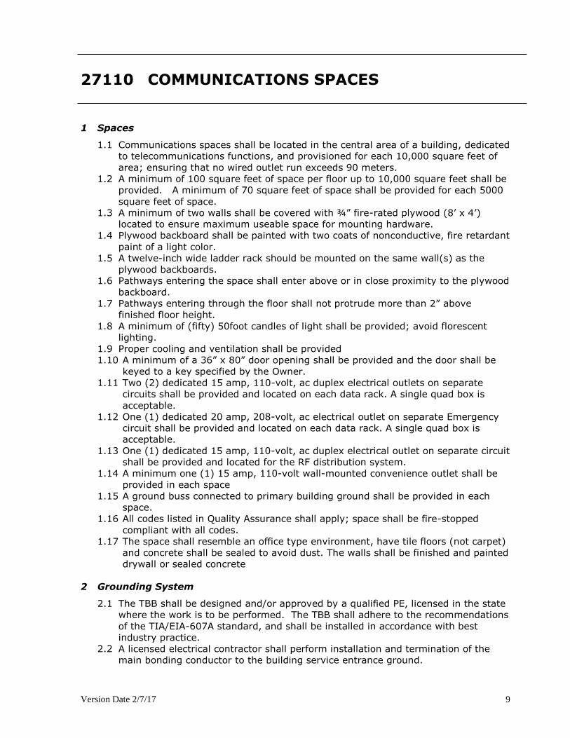
1.1 Communications spaces shall be located in the central area of a building, dedicated
to telecommunications functions, and provisioned for each 10,000 square feet of
area; ensuring that no wired outlet run exceeds 90 meters.
1.2 A minimum of 100 square feet of space per floor up to 10,000 square feet shall be
provided. A minimum of 70 square feet of space shall be provided for each 5000
square feet of space.
1.3 A minimum of two walls shall be covered with ¾” fire-rated plywood (8’ x 4’)
located to ensure maximum useable space for mounting hardware.
1.4 Plywood backboard shall be painted with two coats of nonconductive, fire retardant
paint of a light color.
1.5 A twelve-inch wide ladder rack should be mounted on the same wall(s) as the
plywood backboards.
1.6 Pathways entering the space shall enter above or in close proximity to the plywood
backboard.
1.7 Pathways entering through the floor shall not protrude more than 2” above
finished floor height.
1.8 A minimum of (fifty) 50foot candles of light shall be provided; avoid florescent
lighting.
1.9 Proper cooling and ventilation shall be provided
1.10 A minimum of a 36” x 80” door opening shall be provided and the door shall be
keyed to a key specified by the Owner.
1.11 Two (2) dedicated 15 amp, 110-volt, ac duplex electrical outlets on separate
circuits shall be provided and located on each data rack. A single quad box is
acceptable.
1.12 One (1) dedicated 20 amp, 208-volt, ac electrical outlet on separate Emergency
circuit shall be provided and located on each data rack. A single quad box is
acceptable.
1.13 One (1) dedicated 15 amp, 110-volt, ac duplex electrical outlet on separate circuit
shall be provided and located for the RF distribution system.
1.14 A minimum one (1) 15 amp, 110-volt wall-mounted convenience outlet shall be
provided in each space
1.15 A ground buss connected to primary building ground shall be provided in each
space.
1.16 All codes listed in Quality Assurance shall apply; space shall be fire-stopped
compliant with all codes.
1.17 The space shall resemble an office type environment, have tile floors (not carpet)
and concrete shall be sealed to avoid dust. The walls shall be finished and painted
drywall or sealed concrete
2 Grounding System
2.1 The TBB shall be designed and/or approved by a qualified PE, licensed in the state
where the work is to be performed. The TBB shall adhere to the recommendations
of the TIA/EIA-607A standard, and shall be installed in accordance with best
industry practice.
2.2 A licensed electrical contractor shall perform installation and termination of the
main bonding conductor to the building service entrance ground.

Version Date 2/7/17 10
27120 BUILDING SERVICE ENTRANCES
1 Entrance Facilities
1.1 The locations and size of the building entrance shall be appropriate for application
and placed no farther than 50 feet from the primary communications space for
copper cabling.
1.2 If actual entrance is farther than 50 feet from the primary communications space,
a rigid, metallic and grounded conduit, sized for the application, shall be installed
to extend to the communications space.
1.3 All open space in the pathway system and empty pathways shall be plugged with a
rubber conduit plug, water plug, or duct sealer (appropriate for application).
1.4 A ¾” metallic conduit for primary building ground wires, from the entrance
location to primary building ground location, shall be provided.
1.5 The Owner shall have clear access to the building entrance at all times.
1.6 A minimum of two (2) 4’ x 8’ x ¾” plywood backboards, installed on two or more
walls, and fireproofed, shall be provided.
1.7 The door to the space shall be provisioned to open outward and have a minimum
opening of 36” x 80”.
1.8 The space shall have one duplex outlet on an emergency power circuit.
1.9 The space shall be safe and environmentally clean.
1.10 A 36” minimum clearance shall be maintained between equipment and working
wall space
1.11 A 30” minimum clearance shall be maintained between equipment and non-
working wall space
2 Grounding System
2.1 The TBB shall be designed and/or approved by a qualified PE, licensed in the state
where the work is to be performed. The TBB shall adhere to the recommendations
of the TIA/EIA-607 A standard, and shall be installed in accordance with best
industry practice.
2.2 The telecommunications entrance facility main grounding busbar shall be connected
back to an earth ground in the electrical entrance facility and building steel as
required.
2.3 A licensed electrical contractor shall perform installation and termination of the
main bonding conductor to the building service entrance ground.
Version Date 2/7/17 11
27130 INTERIOR COMMUNICATIONS PATHWAYS
1 Interior Horizontal Communication Pathways
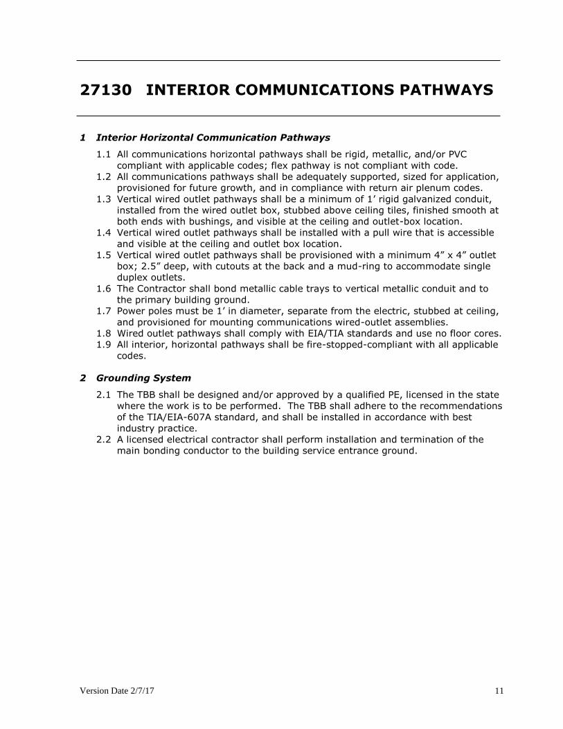
1.1 All communications horizontal pathways shall be rigid, metallic, and/or PVC
compliant with applicable codes; flex pathway is not compliant with code.
1.2 All communications pathways shall be adequately supported, sized for application,
provisioned for future growth, and in compliance with return air plenum codes.
1.3 Vertical wired outlet pathways shall be a minimum of 1’ rigid galvanized conduit,
installed from the wired outlet box, stubbed above ceiling tiles, finished smooth at
both ends with bushings, and visible at the ceiling and outlet-box location.
1.4 Vertical wired outlet pathways shall be installed with a pull wire that is accessible
and visible at the ceiling and outlet box location.
1.5 Vertical wired outlet pathways shall be provisioned with a minimum 4” x 4” outlet
box; 2.5” deep, with cutouts at the back and a mud-ring to accommodate single
duplex outlets.
1.6 The Contractor shall bond metallic cable trays to vertical metallic conduit and to
the primary building ground.
1.7 Power poles must be 1’ in diameter, separate from the electric, stubbed at ceiling,
and provisioned for mounting communications wired-outlet assemblies.
1.8 Wired outlet pathways shall comply with EIA/TIA standards and use no floor cores.
1.9 All interior, horizontal pathways shall be fire-stopped-compliant with all applicable
codes.
2 Grounding System
2.1 The TBB shall be designed and/or approved by a qualified PE, licensed in the state
where the work is to be performed. The TBB shall adhere to the recommendations
of the TIA/EIA-607A standard, and shall be installed in accordance with best
industry practice.
2.2 A licensed electrical contractor shall perform installation and termination of the
main bonding conductor to the building service entrance ground.

Version Date 2/7/17 12
27140 EXTERIOR COMMUNICATIONS PATHWAYS
1 Exterior Communication Pathways
1.1 All exterior communications pathways shall be rigid metallic and/or PVC (not flex),
adequately supported, reamed at each end, clean, dry, and free of debris.
1.2 All exterior communications pathways shall be placed at a minimum depth of 36”.
1.3 All exterior communications pathways shall be sized appropriately for the
application, with provisions for future growth. Each must be installed with a non-
corrosive pulling wire, with a minimum pulling strength of 200 pounds, which is
left in all pathway runs.
1.4 All exterior communications pathways shall have a tracer wire installed end to end
and can be reached with entry to the space.
1.5 All exterior communications pathways shall have a maximum of two (2) 90-degree
bends between pulling points.
1.6 All exterior communications pathways shall protrude not more than 2” into the
floor of the building entrance or other communications spaces.
1.7 All exterior communications pathways shall be bonded/grounded compliant with all
codes listed in the Quality Assurance section.
NOTE: All specifications for exterior communications pathways also apply to interior
vertical/horizontal riser type pathways.
Version Date 2/7/17 13
27150 BACKBONE CABLING REQUIREMENTS
1 General Interior Backbone Cable Installation
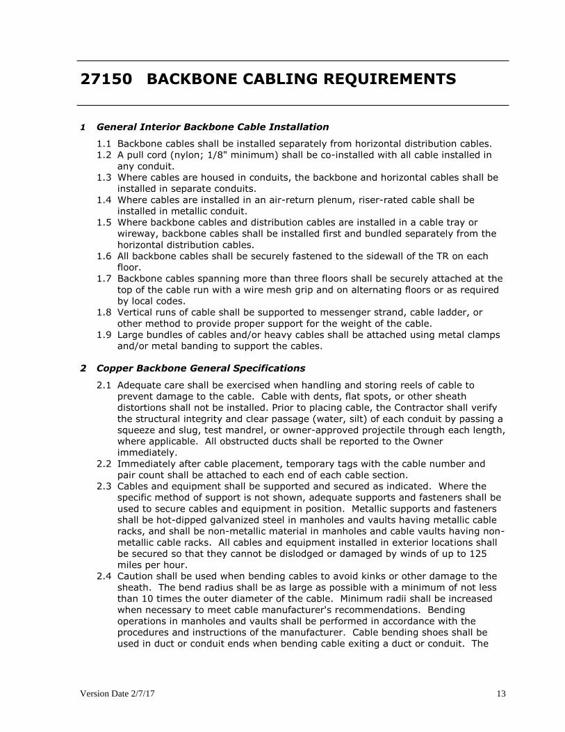
1.1 Backbone cables shall be installed separately from horizontal distribution cables.
1.2 A pull cord (nylon; 1/8" minimum) shall be co-installed with all cable installed in
any conduit.
1.3 Where cables are housed in conduits, the backbone and horizontal cables shall be
installed in separate conduits.
1.4 Where cables are installed in an air-return plenum, riser-rated cable shall be
installed in metallic conduit.
1.5 Where backbone cables and distribution cables are installed in a cable tray or
wireway, backbone cables shall be installed first and bundled separately from the
horizontal distribution cables.
1.6 All backbone cables shall be securely fastened to the sidewall of the TR on each
floor.
1.7 Backbone cables spanning more than three floors shall be securely attached at the
top of the cable run with a wire mesh grip and on alternating floors or as required
by local codes.
1.8 Vertical runs of cable shall be supported to messenger strand, cable ladder, or
other method to provide proper support for the weight of the cable.
1.9 Large bundles of cables and/or heavy cables shall be attached using metal clamps
and/or metal banding to support the cables.
2 Copper Backbone General Specifications
2.1 Adequate care shall be exercised when handling and storing reels of cable to
prevent damage to the cable. Cable with dents, flat spots, or other sheath
distortions shall not be installed. Prior to placing cable, the Contractor shall verify
the structural integrity and clear passage (water, silt) of each conduit by passing a
squeeze and slug, test mandrel, or owner-approved projectile through each length,
where applicable. All obstructed ducts shall be reported to the Owner
immediately.
2.2 Immediately after cable placement, temporary tags with the cable number and
pair count shall be attached to each end of each cable section.
2.3 Cables and equipment shall be supported and secured as indicated. Where the
specific method of support is not shown, adequate supports and fasteners shall be
used to secure cables and equipment in position. Metallic supports and fasteners
shall be hot-dipped galvanized steel in manholes and vaults having metallic cable
racks, and shall be non-metallic material in manholes and cable vaults having non-
metallic cable racks. All cables and equipment installed in exterior locations shall
be secured so that they cannot be dislodged or damaged by winds of up to 125
miles per hour.
2.4 Caution shall be used when bending cables to avoid kinks or other damage to the
sheath. The bend radius shall be as large as possible with a minimum of not less
than 10 times the outer diameter of the cable. Minimum radii shall be increased
when necessary to meet cable manufacturer's recommendations. Bending
operations in manholes and vaults shall be performed in accordance with the
procedures and instructions of the manufacturer. Cable bending shoes shall be
used in duct or conduit ends when bending cable exiting a duct or conduit. The
Version Date 2/7/17 14
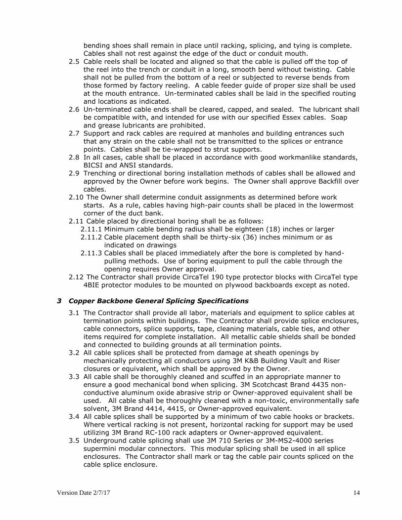
bending shoes shall remain in place until racking, splicing, and tying is complete.
Cables shall not rest against the edge of the duct or conduit mouth.
2.5 Cable reels shall be located and aligned so that the cable is pulled off the top of
the reel into the trench or conduit in a long, smooth bend without twisting. Cable
shall not be pulled from the bottom of a reel or subjected to reverse bends from
those formed by factory reeling. A cable feeder guide of proper size shall be used
at the mouth entrance. Un-terminated cables shall be laid in the specified routing
and locations as indicated.
2.6 Un-terminated cable ends shall be cleared, capped, and sealed. The lubricant shall
be compatible with, and intended for use with our specified Essex cables. Soap
and grease lubricants are prohibited.
2.7 Support and rack cables are required at manholes and building entrances such
that any strain on the cable shall not be transmitted to the splices or entrance
points. Cables shall be tie-wrapped to strut supports.
2.8 In all cases, cable shall be placed in accordance with good workmanlike standards,
BICSI and ANSI standards.
2.9 Trenching or directional boring installation methods of cables shall be allowed and
approved by the Owner before work begins. The Owner shall approve Backfill over
cables.
2.10 The Owner shall determine conduit assignments as determined before work
starts. As a rule, cables having high-pair counts shall be placed in the lowermost
corner of the duct bank.
2.11 Cable placed by directional boring shall be as follows:
2.11.1 Minimum cable bending radius shall be eighteen (18) inches or larger
2.11.2 Cable placement depth shall be thirty-six (36) inches minimum or as
indicated on drawings
2.11.3 Cables shall be placed immediately after the bore is completed by hand-
pulling methods. Use of boring equipment to pull the cable through the
opening requires Owner approval.
2.12 The Contractor shall provide CircaTel 190 type protector blocks with CircaTel type
4BIE protector modules to be mounted on plywood backboards except as noted.
3 Copper Backbone General Splicing Specifications
3.1 The Contractor shall provide all labor, materials and equipment to splice cables at
termination points within buildings. The Contractor shall provide splice enclosures,
cable connectors, splice supports, tape, cleaning materials, cable ties, and other
items required for complete installation. All metallic cable shields shall be bonded
and connected to building grounds at all termination points.
3.2 All cable splices shall be protected from damage at sheath openings by
mechanically protecting all conductors using 3M K&B Building Vault and Riser
closures or equivalent, which shall be approved by the Owner.
3.3 All cable shall be thoroughly cleaned and scuffed in an appropriate manner to
ensure a good mechanical bond when splicing. 3M Scotchcast Brand 4435 non-
conductive aluminum oxide abrasive strip or Owner-approved equivalent shall be
used. All cable shall be thoroughly cleaned with a non-toxic, environmentally safe
solvent, 3M Brand 4414, 4415, or Owner-approved equivalent.
3.4 All cable splices shall be supported by a minimum of two cable hooks or brackets.
Where vertical racking is not present, horizontal racking for support may be used
utilizing 3M Brand RC-100 rack adapters or Owner-approved equivalent.
3.5 Underground cable splicing shall use 3M 710 Series or 3M-MS2-4000 series
supermini modular connectors. This modular splicing shall be used in all splice
enclosures. The Contractor shall mark or tag the cable pair counts spliced on the
cable splice enclosure.
Version Date 2/7/17 15
3.6 The Contractor shall not splice any outside cables without approval of the Owner.
3.7 Splicing of cross-connect terminals and secondary cable access stubs not in line, or
straight splice or diminis/taper splice locations shall use Scotchlock - ULG splicing
connectors or Owner-approved equivalent.
3.8 Cable splices shall be performed in accordance with manufacturer specifications
and with good workmanlike standards, BICSI standards and ANSI standards.
3.9 All metallic cable shields shall be grounded by a #6AWG minimum ground wire to
a low-resistance ground, in compliance with EIA/TIA 607 A standards. The
Contractor in each closet shall provide connections to new grounding buss bars.
The grounding bus bar shall be connected back to the main grounding busbar in
the telecommunications entrance facility, grounded to an earth ground in the
electrical entrance facility, and building steel on each floor as required.
4 Fiber Optic Backbone General Specifications
4.1 Fiber optic cables shall be free of material and manufacturing defects and free of
dimensional non-uniformities that would seriously impair the functionality of the
cables. The fiber optic cables shall also be free from surface imperfections and
internal defects that would prevent them from meeting the mechanical and
transmission requirements of this Specification.
4.2 The fiber optic cables shall be terminated into rack-mounted fiber optic patch
panels. The final fiber optic patch panel shall consist of the applicable fibers field
terminated onto field installable SC connectors. Pre-connectorized fiber
assemblies (pigtails) shall not be used. Each connector shall exhibit an insertion
loss of 0.5 dB or less and a return loss of .30dB or better.
4.3 Personnel who have had at least three (3) years experience in placing cables in
conduit, cable trays, and underground duct systems shall perform Cable
installation work.
4.4 Fiber-optic cable terminations and testing shall be made by journeymen cable
splicers who have had a minimum of three (3) years experience in terminating and
one (1) year in testing fiber optic cables.
4.5 Cables shall be provided in continuous lengths, without splices, from termination
to termination.
4.6 Cables and equipment shall be supported and secured; metallic supports and
fasteners shall have a corrosion-resistant finish.
4.7 Utilizing Panduit J-Mod System (j-hook) or equivalent (no bridal rings) and velcro
cable ties shall be used as necessary to properly secure the cable. Exposed cable
runs in communications closets shall be protected with inner-duct and secured to
walls, cable trays, and racks.
4.8 Caution shall be used when bending cable to avoid kinks or other damage to the
sheath. The bend radius shall be as large as possible with a minimum of ten (10)
inches. Minimum radius shall be increased when necessary to meet cable
manufacturer's recommendation.
4.9 Adequate pulling lubricant shall be used to minimize pulling tension and prevent
sheath damage when pulling cables. Lubricant shall be applied to the cable sheath
with a lubricator. When pulling has been completed, the exposed cable ends shall
be wiped clean of lubricant. All lubricant spills shall be cleaned up immediately.
Lubricants shall be certified by the lubricant manufacturer to be compatible with
and intended for use with plastic sheathed cables. Soap and grease type
lubricants are prohibited.
4.10 It shall be the Contractor's responsibility to ensure that the cable-pulling
procedures being used do not exceed the maximum pulling tension as specified by
the cable manufacturer.
Version Date 2/7/17 16
4.11 The cable shall be carefully inspected for sheath defects or other irregularities, as
it is pulled out from the reel. If defects are detected, pulling shall stop
immediately and the cable section shall be repaired or replaced at the discretion of
the Owner. A system of communications, visual or otherwise, shall be maintained
between pulling and feed locations so that pulling can be stopped instantly, if
necessary.
5 Optical Fiber Termination Hardware
5.1 Fiber slack shall be neatly coiled within the fiber splice tray or enclosure.
5.2 Each cable shall be individually attached to the respective fiber enclosure by
mechanical means. The cable strength member shall be securely attached to the
cable strain-relief bracket in the enclosure.
5.3 Each fiber bundle shall be stripped upon entering the splice tray and the individual
fibers routed in the splice tray.
5.4 Each cable shall be clearly labeled at the entrance to the splice enclosure. Cables
labeled within the bundle shall not be acceptable.
5.5 A maximum of 12 strands of fiber shall be spliced in each tray.
5.6 All spare strands shall be installed into spare splice trays.
6 Coaxial Backbone General Specifications
6.1 The cable shall not be subjected to a bend radius less than that specified by the
cable manufacturer during installation. Extreme caution shall be exercised to
protect the outer layer of the cable from puncture by building projections and
other objects. Punctured sections of cable shall be replaced at the Contractor's
expense.
6.2 The appropriate coring and cable preparation tool shall be used in all splicing.
6.3 Housing-to-housing adapters and right angle fittings shall be used in all locations
where possible. No reverse loops shall be allowed.
6.4 All passive devices shall be strand mounted or supported by a special standoff
bracket when the housing mount cannot be used, or when interconnected to
another device by an entry-to-entry connector.
6.5 Splicers shall use 75-ohm resistor/jumpers and an ohmmeter in the following
manner to ensure no opens or shorts in the line.
6.5.1 A 75-ohm resistor shall be attached to one end of the cable section to be
spliced by connecting one side to the center conductor and the other to the
shield. Zero the ohmmeter and measure the resistor being used; mark that
reading on the meter face with a grease pencil or triangular piece of tape.
The splicer can now continue to the next device and prepare the cable using
the DST/SST-appropriate coring tool and clean the center conductor, then
measure the center conductor to ground. The reading should be
approximately the same as the reference measurement. The device is then
installed and the output measurement taken and should read the same. If
the device installed is a line extender or trunk amplifier, a continuity jumper
(no resistor) should be placed from center conductor to center conductor. A
special 75-ohm jumper can be placed in a bridger amplifier to allow the
splicer to work from the amplifier to the terminating tap. This jumper shall
have an alligator clip and lead soldered to one side of four (4) 75 ohm
resistors which is connected to a ground while an individual lead and clip are
soldered to the other end of each 75 ohm resistor for connection to the
bridger port center conductor.
6.6 Grounding Systems: The grounding system shall be in accordance with applicable
portions of NFPA No. 78, UL-467 and ANSI EIA/TIA 607 and shall be a continuity
system at each station. Conductor connections to ground rods, buried conductors,

Version Date 2/7/17 17
and coaxial grounding clamps shall be made with noncorrosive exothermic weld or
non-bolted compression type bonding clamps. Fences and other fixed metallic
equipment of any type within ten (10) feet of the ground or radial extensions shall
be bonded to the grounding system. Connections to coaxial lines shall be made
with manufacturers' recommended grounding kits. Bonding of dissimilar metals
shall be made only with approved type connectors. Electronic components in the
cable distribution plant shall be directly connected to the ground system. Each
cable shall be grounded with a grounding block at the point of building
penetration, and the grounding block shall be directly connected to a ground
system.

Version Date 2/7/17 18
27160 HORIZONTAL CABLING REQUIREMENTS
1. Work Area Outlets
1.1. The wire outlet assemblies shall be a 4' x 4" box with mud ring to reduce the
presentation to a single gang box and with a 1" rigid conduit stubbed at the ceiling
with a pulling wire.
1.2. If the walls cannot be fished, the wire shall be installed in approved surface
raceway following special guidelines for raceway usage.
1.3. Cables shall be coiled in the in-wall or surface-mount boxes if adequate space is
present to house the cable coil without exceeding the manufacturers bend radius.
In hollow wall installations where box-eliminators are used, excess wire can be
stored in the wall. No more than 12” of UTP and 36” of fiber slack shall be stored
in an in-wall box, modular furniture raceway, or insulated walls. Excess slack shall
be loosely coiled and stored in the ceiling above each drop location when there is
not enough space present in the outlet box to store slack cable.
1.4. Cables shall be dressed and terminated in accordance with the recommendations
made in the TIA/EIA-568-B document, manufacturer's recommendations, and best
industry practices.
1.5. Pair untwist at the termination shall not exceed 3.18mm (0.125 inch).
1.6. Bend radius of the cable in the termination area shall not be less than four (4)
times the outside diameter of the cable.
1.7. The cable jacket shall be maintained to within 25mm (one inch) of the termination
point.
1.8. Data jacks, unless otherwise noted in drawings, shall be located in the bottom
position(s) of each faceplate. Data jacks in horizontally oriented faceplates shall
occupy the right-most position(s).
1.9. Voice jacks shall occupy the top position(s) on the faceplate. Voice jacks in
horizontally oriented faceplates shall occupy the left-most position(s).
2. Horizontal Distribution Cable Installation
2.1 Cable shall be installed in accordance with manufacturer’s recommendations and
best industry practices.
2.2 A pull cord (nylon; 1/8" minimum) shall be co-installed with all cable installed in
any conduit.
2.3 Cable raceways shall not be filled greater than the TIA/EIA-569-A maximum fill for
the particular raceway type or 40%.
2.4 Cables shall be installed in continuous lengths from origin to destination (no
splices) except for transition points or consolidation points.
2.5 Where transition points or consolidation points are allowed, they shall be located in
accessible locations and housed in an enclosure intended and suitable for the
purpose.
2.6 The cable’s minimum bend radius and maximum pulling tension shall not be
exceeded.
2.7 If a J-hook or trapeze system is used to support cable bundles, all horizontal
cables shall be supported at a maximum of 48-inch intervals and 24-inch
maximum for all exposed vertical cable runs. At no point shall cable(s) rest on
acoustic ceiling grids or panels.

Version Date 2/7/17 19
2.8 Cable bundling shall be minimized in all horizontal cable runs. When necessary,
horizontal distribution cables shall be bundled in groups of no more than 50
cables. Cable bundle quantities in excess of 50 cables may cause deformation of
the bottom cables within the bundle and degrade cable performance.
2.9 Cable shall be installed above fire-sprinkler systems and shall not be attached to
the system or any ancillary equipment or hardware. The cable system and
support hardware shall be installed so that it does not obscure any valves, fire
alarm conduit, boxes, or other control devices.
2.10 Cables shall not be attached to ceiling grid or lighting fixture wires. Where
support for horizontal cable is required, the contractor shall install appropriate
carriers to support the cabling.
2.11 Any cable damaged or exceeding recommended installation parameters during
installation shall be replaced by the contractor prior to final acceptance and at no
cost to the Owner.
2.12 Cables shall be identified by a self-adhesive label in accordance with the System
Documentation Section of this specification and ANSI/TIA/EIA-606. The cable
label shall be applied to the cable behind the faceplate on a section of cable that
can be accessed by removing the cover plate.
2.13 Unshielded twisted pair cable shall be installed so there are no bends smaller than
four (4) times the cable outside diameter at any point in the run and at the
termination field.
2.14 Pulling tension on 4-pair UTP cables shall not exceed 25-lbf for a four-pair UTP
cable.
3 Voice/Telemetry Horizontal Wiring General Specifications
3.1 Category 5e voice/telemetry horizontal wires shall be installed from the BDF/IDF to
the wired outlets at each location indicated on drawings in compliance with EIA/TIA
568B standard.
3.2 Horizontal wires shall be installed in Owner-provided pathways as indicated on
drawings.
3.3 The Contractor shall identify each wire for an orderly installation.
3.4 All voice/telemetry horizontal wires shall be terminated on Panduit rack mounted
patch panels.
3.5 The Contractor shall terminate horizontal wires in an orderly fashion, using strain
relief and cable management mechanisms.
3.6 Cable bundling shall be minimized in all cable runs. When necessary, the Contractor
shall install bundles of wires in vertical chase ways outside of conduits; bind all
wires together in one bundle in order to provide strain relief for the wires, and sire
bundle to existing structures.
3.7 The Contractor shall ensure that during the installation, nicks, abrasions, burning,
and scuffing of wires is prevented. Wires found to be damaged shall be replaced
at the Contractor's expense regardless of whether the wire passes testing.
3.8 Power poles, if necessary, shall have a separate section from the electric wires.
3.9 All horizontal wires shall be concealed.
3.10 Sleeves, bores, fire rated walls and floors, which are penetrated, shall be fire-
stopped according to standards and codes.
3.11 All tie wraps shall be logical, at 90-degree angles when possible and supported
from ceilings (not on top of ceiling tiles).
3.12 RJ31X shall be used whenever an extension is to be bridged to a security or fire
alarm system and wired as follows:
3.12.1 At the station cable far end:
Version Date 2/7/17 20
3.12.1.1 The blue/white pair shall be connected to terminals 4&5 of the
RJ31X.
3.12.1.2 The orange/white pair shall be connected to terminals 1&8 of the
RJ31X.
3.12.2 Cross connect as follows:
3.12.2.1 A feeder pair connected to the analog port in the MDF shall be
connected through to the station cable blue/white pair and
terminals 4&5 of the RJ31X.
3.12.2.2 A second feeder pair from the MDF shall be connected through to
the orange/white pair and terminals 1&8 of the RJ31X.
3.12.2.3 A third feeder pair from the MDF shall be connected through to
the desired analog phone extension that has the same extension
number as the RJ31X.
3.12.2.4 A final cross connect is placed between the second feeder pair to
the third feeder pair.
4 Data Wiring General Specifications
4.1 SAME AS VOICE/TELEMETRY
4.2 The Contractor shall provide vertical and horizontal cable management as noted in
materials section.
4.3 The Contractor shall mount racks according to plan supplied by the Owner
4.4 The Contractor shall ground rack to equipment ground bar using a #6 AWG wire.
4.5 All data wires shall be terminated with slack loops to facilitate the movement of any
wire to any port on the patch panel and rack.
5 Horizontal Cross Connect Installation
5.1 Cables shall be dressed and terminated in accordance with the recommendations
made in the TIA/EIA-568-B standard, manufacturer's recommendations, and best
industry practices.
5.2 Pair untwist at the termination shall not exceed 3.18 mm (0.125 inch).
5.3 Bend radius of the cable in the termination area shall not exceed four (4) times
the outside diameter of the cable.
5.4 Cables shall be neatly bundled and dressed to their respective panels or blocks.
Each panel or block shall be fed by an individual bundle, separated and dressed
back to the point of cable entrance into the rack or frame.
5.5 The cable jacket shall be maintained as close as possible to the termination point.
5.6 Each cable shall be clearly labeled on the cable jacket, behind the patch panel, at a
location that can be viewed without removing the bundle support ties. Cables
labeled within the bundle, where the label is obscured from view, are not
acceptable.
6 Optical Fiber Termination Hardware
6.1 Fiber slack shall be neatly coiled within the fiber splice tray or enclosure.
6.2 Each cable shall be individually attached to the respective fiber enclosure by
mechanical means. The cable strength member shall be securely attached to the
cable strain relief bracket in the enclosure.
6.3 Each fiber bundle shall be stripped upon entering the splice tray and the individual
fibers routed in the splice tray.
6.4 Each cable shall be clearly labeled at the entrance to the splice enclosure. Cables
labeled within the bundle are not acceptable.
6.5 A maximum of 12 strands of fiber shall be spliced in each tray.
6.6 All spare strands shall be installed into spare splice trays.
Version Date 2/7/17 21
7 Inside Backbone Cable Installation
7.1 Backbone cables shall be installed separately from horizontal distribution cables.
7.2 A pull cord (nylon; 1/8" minimum) shall be co-installed with all cable installed in
any conduit.
7.3 Where cables are housed in conduits, the backbone and horizontal cables shall be
installed in separate conduits.
7.4 Where cables are installed in an air-return plenum, riser-rated cable shall be
installed in metallic conduit.
7.5 Where backbone cables and distribution cables are installed in a cable tray or
wireway, backbone cables shall be installed first and bundled separately from the
horizontal distribution cables.
7.6 All backbone cables shall be securely fastened to the sidewall of the TR on each
floor.
7.7 Backbone cables spanning more than three floors shall be securely attached at the
top of the cable run with a wire mesh grip and on alternating floors or as required
by local codes.
7.8 Vertical runs of cable shall be supported to messenger strand, cable ladder, or
other method, to provide proper support for the weight of the cable.
7.9 Large bundles of cables and/or heavy cables shall be attached using metal clamps
and/or metal banding to support the cables.
8 Copper Termination Hardware
8.1 Cables shall be dressed and terminated in accordance with the recommendations
made in the ANSI/TIA/EIA-568-B standard, manufacturer's recommendations, and
best industry practice.
8.2 Pair untwist at the termination shall not exceed 3.18mm (0.125 inch).
8.3 Bend radius of the cable in the termination area shall not exceed four (4) times
the outside diameter of the cable.
8.4 Cables shall be dressed to their respective panels or blocks. Each panel or block
shall be fed by an individual bundle, separated, and dressed back to the point of
cable entrance into the rack or frame.
8.5 The cable jacket shall be maintained to the termination point.
8.6 Each cable shall be clearly labeled on the cable jacket, behind the patch panel, at a
location that can be viewed without removing the bundle support ties. Cables
labeled within the bundle, where the label is obscured from view, shall not be
acceptable.
9 Racks
9.1 Racks shall be securely attached to the concrete floor using minimum 3/8”
hardware or as required by local codes.
9.2 Racks shall be placed with a 36-inch (minimum) clearance from the walls on all
sides of the rack. When mounted in a row, maintain a minimum of 36 inches from
the wall behind and in front of the row of racks and from the wall at each end of
the row.
9.3 All racks shall be grounded to the telecommunications ground bus bar in
accordance with Section 2.4 of this document.
9.4 Rack mount screws not used for installing patch panels and other hardware shall
be bagged and left with the rack upon completion of the installation.
Version Date 2/7/17 22
9.5 Wall mounted termination block fields shall be mounted on 4’ x 8’ x .75” void-free
plywood. The plywood shall be mounted vertically, 12” above the finished floor.
The plywood shall be painted with two coats of white, fire-retardant paint.
9.6 Wall-mounted termination block fields shall be installed with the lowest edge of the
mounting frame 18” from the finished floor.
10 RF Cable Distribution System
10.1 All cabling must be home run. No taps, Splitters, or splices are to be used
between the main closet distribution and the end users connection plate.
10.2 Each Cable length and cable type must be recorded and made available prior to
the distribution system acceptance.
10.3 All cabling must be a minimum of RG-6 or better.
10.4 All cable runs to rooms up to 200’ should be RG-6 or better
10.5 All cable runs to rooms 200’-300’ should be RG-11 or better
10.6 All risers between floors should be RG-11 or better
10.7 All cabling should be Plenum where required by code.
10.8 All connectors should be industry standard moisture proof compression fittings
NOT crimp style.
10.9 All cabling should be properly labeled with both to and from designations and a
cable number.
10.10 Labels should be wrapping type or be heat shrunk over with clear covering.
11 Firestop System
11.1 All firestop systems shall be installed in accordance with the manufacturer’s
recommendations and shall be completely installed and available for inspection by
the local inspection authorities prior to cable system acceptance.
Version Date 2/7/17 23
27170 TESTING, IDENTIFICATION AND
ADMINISTRATION: BACKBONE CABLING
1 Testing and Acceptance
General
All cables and termination hardware shall be 100% tested for defects in
installation and to verify cabling-system performance under installed
conditions according to the requirements of ANSI/TIA/EIA-568-B. All pairs
of each installed cable shall be verified prior to system acceptance. Any
defect in the cabling system installation, including, but not limited to cable,
connectors, feed through couplers, patch panels, and connector blocks, shall
be repaired or replaced in order to ensure 100% useable conductors in all
cables installed.
All cables shall be tested in accordance with this document, the latest
ANSI/TIA/EIA standards, and best industry practice. If any of these are in
conflict, the Contractor shall bring any discrepancies to the attention of the
project team for clarification and resolution.
Fiber Testing
Fiber testing shall be performed on all fibers in the completed end-to-end
system. There shall be no splices unless clearly defined in an RFP. Testing
shall consist of an end-to-end power meter test performed per TIA/EIA-455-
53A. The system loss measurements shall be provided at 850 and/or 1300
nanometers for multimode fibers and 1310 and/or 1550 nanometers for
single mode fibers. These tests also include continuity checking of each
fiber.
1. For a horizontal cabling system using multimode optical fiber,
attenuation shall be measured in both directions at either 850
nanometer (nm) or 1300 nm using an LED light source and power
meter.
2. Backbone multimode fiber cabling shall be tested at both 850 nm and
1300 nm (or 1310 and 1550 nm for singlemode) in one direction.
3. Test set-up and performance shall be conducted in accordance with
ANSI/TIA/EIA-526-14 Standard, Method B.
4. Where links are combined to complete a circuit between devices, the
Contractor shall test each link from end to end to ensure the
performance of the system. ONLY A BASIC LINK TEST IS REQUIRED.
As an option, the Contractor can install patch cords to complete the
circuit and then test the entire channel. The test method shall be the
same used for the test described above. The values for calculating
loss shall be those defined in the ANSI/TIA/EIA Standard.
5. Attenuation testing shall be performed with a stable launch condition
using two-meter jumpers to attach the test equipment to the cable
plant. The light source shall be left in place after calibration and the
power meter moved to the far end to take measurements.
OTDR TESTS
1.1.1.1 All OTDR testing requires the use of an access jumper (length
determined by OTDR requirements) between the OTDR and the first
connector and after the far end connector. The fiber used in the
Version Date 2/7/17 24
access jumper shall have specifications that are identical to the
fiber under test.
1.1.1.2 After terminations have been completed, each fiber shall have an
OTDR trace made for the entire span, including the access jumpers
as described above. The tests shall be performed in both directions
using the OTDR and shall be stored on diskettes. Tests on
Multimode fibers shall be performed at 1,300 (+/-) 20 nanometers.
Tests on Singlemode fibers shall be performed at 1,550 (+/-) 20
nanometers.
1.1.1.3 As part of the test data submittal, the Contractor shall provide
(with the diskettes) two copies of the necessary software that
allows the traces to be displayed by a PC.
1.1.1.4 When viewed on the OTDR traces, the following test results shall be
met:
1.1.1.4.1 Connector losses -mated connector pairs shall exhibit an
insertion loss, as measured by the OTDR, of no more than
0.8 dB per mated connector pair.
1.1.1.4.2 Splice losses - fusion splices, where specified and allowed
in the specifications, shall exhibit a bi-directional average
splice loss as measured by the OTDR of no more than 0.2
dB per fusion splice.
1.1.2 Submittal of Test Results
1.1.2.1 Three copies of all test result data shall be submitted to the Owner
for review. The installer shall maintain an accurate test record
during all field tests. If installer-developed data sheets are used for
recording test data, samples of the sheets shall be submitted for
approval.
1.1.2.2 Along with the OTDR test data submittal, the Contractor shall
provide with the diskettes, two licensed versions of the necessary
software that allows the OTDR traces to be displayed by PC. This
software shall be purchased from the OTDR manufacturer or
retailer.
Coaxial Testing
A time domain reflectometry test shall be conducted on each newly installed
cable section to determine shorts, opens, and other impedance
discontinuities and their locations. Impedance discontinuities that would
adversely affect the system's ability to meet the requirements of this
specification shall be corrected.
Each trunk/feeder cable placed shall be sweep tested from 50-1000 MHz and
tested with a Time Domain Reflectometer (TDR). Performance of the cable
over the link shall meet or exceed manufacturer's published specifications.
Documentation of performance testing shall be included.
2 System Documentation
Upon completion of the installation, the telecommunications contractor shall
provide three (3) full documentation sets to the Owner for approval.
Documentation shall include the items detailed in the sub-sections below.
Documentation shall be submitted within ten (10) working days of the completion
of each testing phase. This is inclusive of all test results and draft as-built drawings.
Draft drawings may include annotations done by hand. Machine generated (final)
copies of all drawings shall be submitted within thirty (30) working days of the
completion of each testing phase. At the request of the Owner, the
telecommunications contractor shall provide copies of the original test results.

Version Date 2/7/17 25
The Owner may request a 10% random field re-test be conducted on the cable
system, at no additional cost, to verify documented findings. Tests shall be a
repeat of those defined above. If findings contradict the documentation submitted
by the telecommunications contractor, additional testing can be requested to the
extent determined necessary by the Owner, including a 100% re-test. This re-test
shall be at no additional cost to the Owner.
Test Results documentation shall be provided on disk within three (3) weeks after
the completion of the project. The disk shall be clearly marked on the outside front
cover with the words “Project Test Documentation,” the project name, and the date
of completion (month and year). The results shall include a record of test
frequencies, cable type, conductor pair and cable (or outlet) I.D., measurement
direction, reference setup, and crew member name(s). The test equipment name,
manufacturer, model number, serial number, software version and last calibration
date will also be provided at the end of the document. Unless the manufacturer
specifies a more frequent calibration cycle, an annual calibration cycle is anticipated
on all test equipment used for this installation. The test document shall detail the
test method used and the specific settings of the equipment during the test as well
as the software version being used in the field test equipment.
The field test equipment shall meet the requirements of ANSI/TIA/EIA-568-B
including applicable TSB’s and amendments. The appropriate level III tester shall
be used to verify Category 5e and 6a cabling systems.
Printouts generated for each cable by the wire (or fiber) test instrument shall be
submitted as part of the documentation package. Alternately, the
telecommunications contractor may furnish this information in electronic form.
These diskettes shall contain the electronic equivalent of the test results as defined
by the bid specification and be of a format readable using Microsoft Word.
When repairs and re-tests are performed, the problem found and corrective action
taken shall be noted, and both the failed and passed test data shall be documented.
The As-Built drawings are to include cable routes and outlet locations. Their
sequential number, as defined elsewhere in this document, shall identify outlet
locations. Numbering, icons, and drawing conventions used shall be consistent
throughout all documentation provided. The Owner will provide floor plans in paper
and electronic (DWG, AutoCAD) formats on which as-built construction information
can be added. These documents will be modified accordingly by the
telecommunications contractor to denote as-built information as defined above and
returned to the Owner.
The Contractor shall annotate the base drawings and return a hard copy (same plot
size as originals) and electronic (AutoCAD) form.
Version Date 2/7/17 26
27170A TESTING, IDENTIFICATION, AND
ADMINISTRATION: HORIZONTAL WIRING
1. Testing and Identification/Labeling Specification for Copper Horizontal
Cabling
1.1 Copper Channel Testing
1.1.1 All twisted-pair copper cable links shall be tested for continuity, pair
reversals, shorts, opens, and performance as indicated below. Additional
testing is required to verify Category performance. Horizontal cabling shall
be tested using a level IIe or level III test unit for Category 5e or Category
6a performance compliance, respectively
1.1.1.1 Continuity - Each pair of each installed cable shall be tested using a
test unit that shows opens, shorts, polarity and pair-reversals,
crossed pairs, and split pairs. Shielded/screened cables shall be
tested with a device that verifies shield continuity in addition to the
above stated tests. The test shall be recorded as pass/fail as
indicated by the test unit in accordance with the manufacturers’
recommended procedures, and referenced to the appropriate cable
identification number and circuit or pair number. Any faults in the
wiring shall be corrected and the cable re-tested prior to final
acceptance.
1.1.1.2 Length - Each installed cable link shall be tested for installed length
using a TDR type device. The cables shall be tested from patch
panel to patch panel, block to block, patch panel to outlet, or block
to outlet as appropriate. The cable length shall conform to the
maximum distances set forth in the ANSI/TIA/EIA-568-A Standard.
Cable lengths shall be recorded, referencing the cable identification
number and circuit or pair number. For multi-pair cables, the
shortest pair length shall be recorded as the length for the cable.
1.1.1.3 Category 5e & 6 Performance
1.1.1.3.1 Follow the standards requirements established in
ANSI/TIA/EIA-568-B
1.1.1.3.2 A level III test unit is required to verify Category 5e and
Category 6a performances.
1.2 Labeling Of Horizontal Cables
1.2.1 Labeling of all wires and terminations shall be in a manner specified by the
Owner at start of work.
1.2.2 Wired outlet assemblies shall be labeled as follows:
1.2.2.1 BB-CC-RRRR-J
1.2.2.1.1 B 2or 3digit building number
1.2.2.1.2 CC 2character BDF/IDF number
1.2.2.1.3 RRRR 4character room number
1.2.2.1.4 J 1–3-digit jack number
2 Testing and Identification/Labeling Specification for Fiber Optic Horizontal
Cabling
2.1 Labeling is the same as for copper horizontal wiring.
Version Date 2/7/17 27
2.2 Testing is the same as for fiber optic backbone cable.
3 Testing and Identification/Labeling Specification for Coaxial Horizontal
Cabling
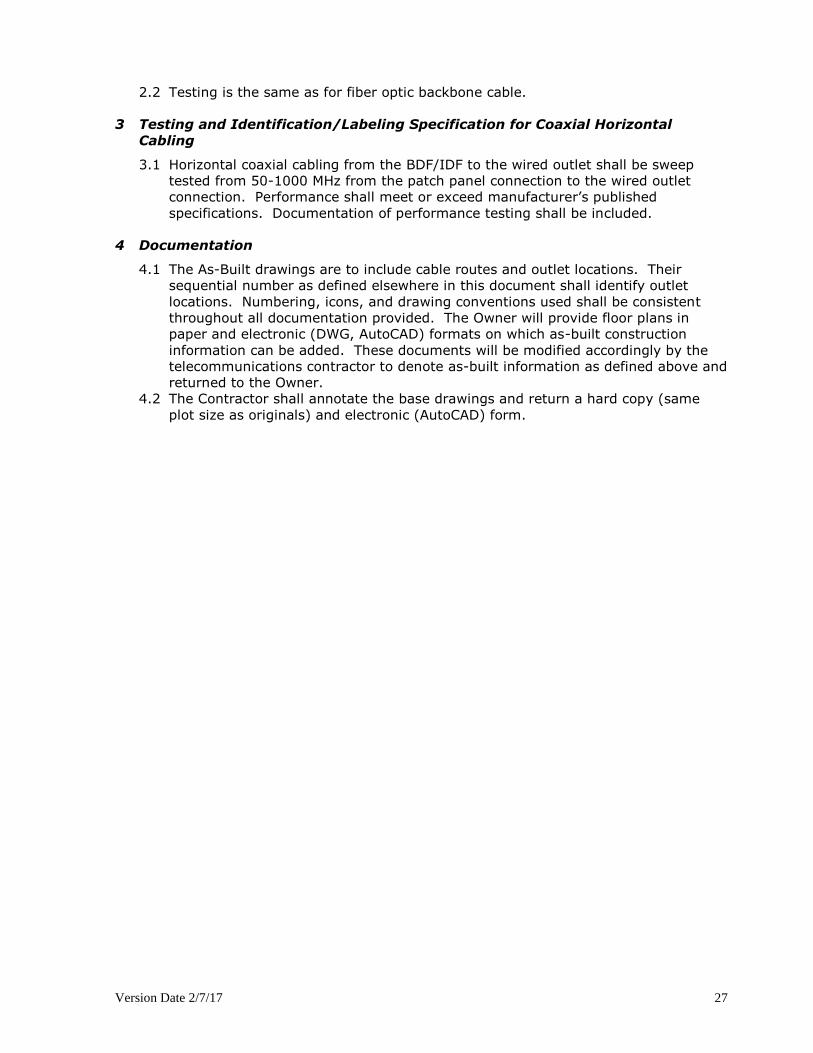
3.1 Horizontal coaxial cabling from the BDF/IDF to the wired outlet shall be sweep
tested from 50-1000 MHz from the patch panel connection to the wired outlet
connection. Performance shall meet or exceed manufacturer’s published
specifications. Documentation of performance testing shall be included.
4 Documentation
4.1 The As-Built drawings are to include cable routes and outlet locations. Their
sequential number as defined elsewhere in this document shall identify outlet
locations. Numbering, icons, and drawing conventions used shall be consistent
throughout all documentation provided. The Owner will provide floor plans in
paper and electronic (DWG, AutoCAD) formats on which as-built construction
information can be added. These documents will be modified accordingly by the
telecommunications contractor to denote as-built information as defined above and
returned to the Owner.
4.2 The Contractor shall annotate the base drawings and return a hard copy (same
plot size as originals) and electronic (AutoCAD) form.

Version Date 2/7/17 28
27190 WARRANTY
1. The Contractor warrants that all services performed under this agreement shall be
performed in a thorough and professional manner in conformance with the
standards of the industry. The Contractor shall correct, at his expense, all defects
or deficiencies in the work, which result from the material furnished by the
Contractor, workmanship, or failure to follow the plans, drawings, or other
specifications made part of this contract. Those defects or deficiencies discovered
within five (5) years from the date of acceptance (acceptance of the work by the
Owner shall not constitute a waiver of such defects or deficiencies) may be
remedied by the Owner and the Contractor shall pay the Owner the cost of making
such corrections.
2. All fiber optic materials and work shall be covered under the applicable
manufacturer’s warranty. A certificate of Project Registration shall be on file at
start of work.
3. All horizontal copper wiring materials and work shall be covered under the Panduit
Network Systems Certification Plus System Warranty Program. A certificate of
Project Registration shall be on file at start of work.
4. The Owner will work with the successful bidder to obtain necessary warranty
participation from the manufacturers.
5. All copper backbone materials and work shall be under warranty for five (5) full
years from date of final acceptance.
6. All copper horizontal wire materials and work shall be under warranty for five (5)
full years from date of final acceptance.
7. All other materials and work shall be under warranty for five (5) full years from
date of final acceptance.
Version Date 2/7/17 29
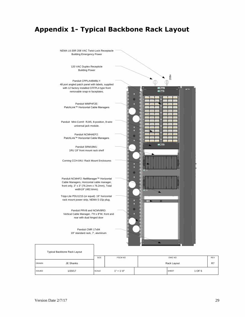
Appendix 1- Typical Backbone Rack Layout
1
5
10
15
20
25
30
35
40
45
2
3
4
6
7
8
9
11
12
13
14
16
17
18
19
21
22
23
24
26
27
28
29
31
32
33
34
36
37
38
39
41
42
43
44
1
5
10
15
20
25
30
35
40
45
2
3
4
6
7
8
9
11
12
13
14
16
17
18
19
21
22
23
24
26
27
28
29
31
32
33
34
36
37
38
39
41
42
43
44
Panduit CMR 17x84
19" standard rack, 7', aluminum
241
4825
241
4825
241
4825
Typical Backbone Rack Layout
SIZE FSCM NO DWG NO REV
DRAWN JE Shanks Rack Layout R7
ISSUED 1/20/17 SCALE 1" = 1'-0" SHEET 1 OF 5
120 VAC Duplex Recepticle
Building Power
241
4825
241
4825
Panduit WMPHF2E:
PatchLink™ Horizontal Cable Managers
Panduit Mini-Com® RJ45, 8-position, 8-wire
universal jack module.
241
4825
Panduit PRV8 and NCMV8RD:
Vertical Cable Manager, 7'H x 8"W, front and
rear with dual hinged door
20
8v
NEMA L6-30R 208 VAC Twist-Lock Receptacle
Building Emergency Power
A B C D E F G H I J K L
A B C D E F G H I J K L
Corning CCH-04U: Rack Mount Enclosures
Panduit NCMHF2: NetManager™ Horizontal
Cable Managers, Horizontal cable manager,
front only, 3" x 3" (76.2mm x 76.2mm), Total
width19" (482.6mm).
241
4825
Panduit CPPLA48WBLY:
48 port angled patch panel with labels, supplied
with 12 factory installed CFFPL4 type front
removable snap-in faceplates.
Panduit NCMHAEF2:
PatchLink™ Horizontal Cable Managers
Panduit SRM19M1:
1RU 19" front mount rack shelf
Tripp-Lite PDU1215 (or equal): 19" horizontal
rack mount power strip, NEMA 5-15p plug.
Version Date 2/7/17 30
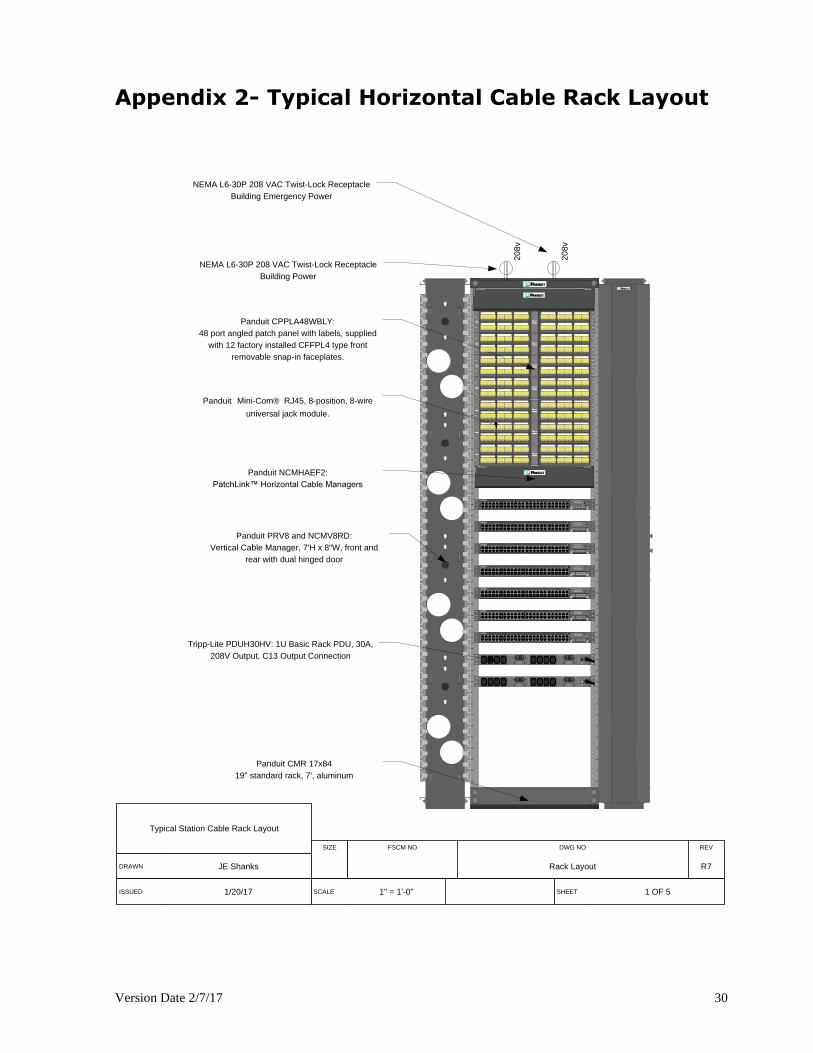
Appendix 2- Typical Horizontal Cable Rack Layout
20
8v
Panduit PRV8 and NCMV8RD:
Vertical Cable Manager, 7'H x 8"W, front and
rear with dual hinged door
NEMA L6-30P 208 VAC Twist-Lock Receptacle
Building Power
Typical Station Cable Rack Layout
SIZE FSCM NO DWG NO REV
DRAWN JE Shanks Rack Layout R7
ISSUED 1/20/17 SCALE 1" = 1'-0" SHEET 1 OF 5
NEMA L6-30P 208 VAC Twist-Lock Receptacle
Building Emergency Power
1
5
10
15
20
25
30
35
40
45
2
3
4
6
7
8
9
11
12
13
14
16
17
18
19
21
22
23
24
26
27
28
29
31
32
33
34
36
37
38
39
41
42
43
44
1
5
10
15
20
25
30
35
40
45
2
3
4
6
7
8
9
11
12
13
14
16
17
18
19
21
22
23
24
26
27
28
29
31
32
33
34
36
37
38
39
41
42
43
44
241
4825
241
4825
241
4825
241
4825
241
4825
241
4825
241
4825
Panduit CPPLA48WBLY:
48 port angled patch panel with labels, supplied
with 12 factory installed CFFPL4 type front
removable snap-in faceplates.
Panduit Mini-Com® RJ45, 8-position, 8-wire
universal jack module.
Panduit NCMHAEF2:
PatchLink™ Horizontal Cable Managers
Panduit CMR 17x84
19" standard rack, 7', aluminum
0 1 2 3 4 5 6 7 8 9 10 11 12 13 14 15 16 17 18 19 20 21 22 23 24 25 26 27 28 29 30 31 32 33 34 35 35 37 37 39 40 41 42 43 44 45
CON1
47
EX4300 PoE +
0 1 2 3
0 1 2 3 4 5 6 7 8 9 10 11 12 13 14 15 16 17 18 19 20 21 22 23 24 25 26 27 28 29 30 31 32 33 34 35 35 37 37 39 40 41 42 43 44 45
CON1
47
EX4300 PoE +
0 1 2 3
0 1 2 3 4 5 6 7 8 9 10 11 12 13 14 15 16 17 18 19 20 21 22 23 24 25 26 27 28 29 30 31 32 33 34 35 35 37 37 39 40 41 42 43 44 45
CON1
47
EX4300 PoE +
0 1 2 3
0 1 2 3 4 5 6 7 8 9 10 11 12 13 14 15 16 17 18 19 20 21 22 23 24 25 26 27 28 29 30 31 32 33 34 35 35 37 37 39 40 41 42 43 44 45
CON1
47
EX4300 PoE +
0 1 2 3
0 1 2 3 4 5 6 7 8 9 10 11 12 13 14 15 16 17 18 19 20 21 22 23 24 25 26 27 28 29 30 31 32 33 34 35 35 37 37 39 40 41 42 43 44 45
CON1
47
EX4300 PoE +
0 1 2 3
0 1 2 3 4 5 6 7 8 9 10 11 12 13 14 15 16 17 18 19 20 21 22 23 24 25 26 27 28 29 30 31 32 33 34 35 35 37 37 39 40 41 42 43 44 45
CON1
47
EX4300 PoE +
0 1 2 3
0 1 2 3 4 5 6 7 8 9 10 11 12 13 14 15 16 17 18 19 20 21 22 23 24 25 26 27 28 29 30 31 32 33 34 35 35 37 37 39 40 41 42 43 44 45
CON1
47
EX4300 PoE +
0 1 2 3
20
8v
200NI
0FFO
BANK 2
200NI
0FFO
BANK 1
Tripp-Lite PDUH30HV: 1U Basic Rack PDU, 30A,
208V Output, C13 Output Connection
200NI
0FFO
BANK 2
200NI
0FFO
BANK 1
Version Date 2/7/17
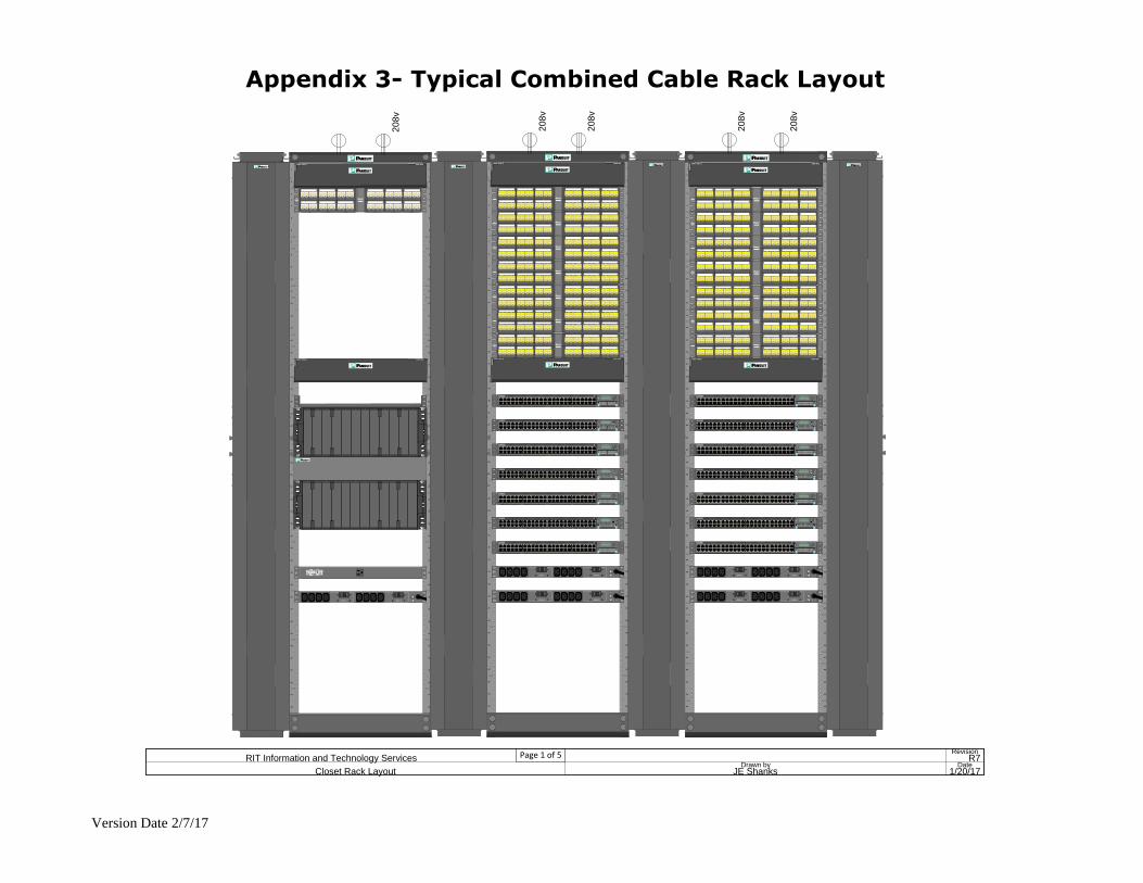
Appendix 3- Typical Combined Cable Rack Layout
1
5
10
15
20
25
30
35
40
45
2
3
4
6
7
8
9
11
12
13
14
16
17
18
19
21
22
23
24
26
27
28
29
31
32
33
34
36
37
38
39
41
42
43
44
1
5
10
15
20
25
30
35
40
45
2
3
4
6
7
8
9
11
12
13
14
16
17
18
19
21
22
23
24
26
27
28
29
31
32
33
34
36
37
38
39
41
42
43
44
1
5
10
15
20
25
30
35
40
45
2
3
4
6
7
8
9
11
12
13
14
16
17
18
19
21
22
23
24
26
27
28
29
31
32
33
34
36
37
38
39
41
42
43
44
1
5
10
15
20
25
30
35
40
45
2
3
4
6
7
8
9
11
12
13
14
16
17
18
19
21
22
23
24
26
27
28
29
31
32
33
34
36
37
38
39
41
42
43
44
A B C D E F G H I J K L
A B C D E F G H I J K L
241
4825
241
4825
241
4825
241
4825
241
4825
241
4825
241
4825
241
4825
1
5
10
15
20
25
30
35
40
45
2
3
4
6
7
8
9
11
12
13
14
16
17
18
19
21
22
23
24
26
27
28
29
31
32
33
34
36
37
38
39
41
42
43
44
1
5
10
15
20
25
30
35
40
45
2
3
4
6
7
8
9
11
12
13
14
16
17
18
19
21
22
23
24
26
27
28
29
31
32
33
34
36
37
38
39
41
42
43
44
241
4825
241
4825
241
4825
241
4825
241
4825
241
4825
241
4825
Drawn by
JE Shanks
Closet Rack Layout
RevisionR7
Date1/20/17
Page 1 of 5 RIT Information and Technology Services
20
8v
20
8v
20
8v
0 1 2 3 4 5 6 7 8 9 10 11 12 13 14 15 16 17 18 19 20 21 22 23 24 25 26 27 28 29 30 31 32 33 34 35 35 37 37 39 40 41 42 43 44 45
CON1
47
EX4300 PoE +
0 1 2 3
0 1 2 3 4 5 6 7 8 9 10 11 12 13 14 15 16 17 18 19 20 21 22 23 24 25 26 27 28 29 30 31 32 33 34 35 35 37 37 39 40 41 42 43 44 45
CON1
47
EX4300 PoE +
0 1 2 3
0 1 2 3 4 5 6 7 8 9 10 11 12 13 14 15 16 17 18 19 20 21 22 23 24 25 26 27 28 29 30 31 32 33 34 35 35 37 37 39 40 41 42 43 44 45
CON1
47
EX4300 PoE +
0 1 2 3
0 1 2 3 4 5 6 7 8 9 10 11 12 13 14 15 16 17 18 19 20 21 22 23 24 25 26 27 28 29 30 31 32 33 34 35 35 37 37 39 40 41 42 43 44 45
CON1
47
EX4300 PoE +
0 1 2 3
0 1 2 3 4 5 6 7 8 9 10 11 12 13 14 15 16 17 18 19 20 21 22 23 24 25 26 27 28 29 30 31 32 33 34 35 35 37 37 39 40 41 42 43 44 45
CON1
47
EX4300 PoE +
0 1 2 3
0 1 2 3 4 5 6 7 8 9 10 11 12 13 14 15 16 17 18 19 20 21 22 23 24 25 26 27 28 29 30 31 32 33 34 35 35 37 37 39 40 41 42 43 44 45
CON1
47
EX4300 PoE +
0 1 2 3
0 1 2 3 4 5 6 7 8 9 10 11 12 13 14 15 16 17 18 19 20 21 22 23 24 25 26 27 28 29 30 31 32 33 34 35 35 37 37 39 40 41 42 43 44 45
CON1
47
EX4300 PoE +
0 1 2 3
0 1 2 3 4 5 6 7 8 9 10 11 12 13 14 15 16 17 18 19 20 21 22 23 24 25 26 27 28 29 30 31 32 33 34 35 35 37 37 39 40 41 42 43 44 45
CON1
47
EX4300 PoE +
0 1 2 3
0 1 2 3 4 5 6 7 8 9 10 11 12 13 14 15 16 17 18 19 20 21 22 23 24 25 26 27 28 29 30 31 32 33 34 35 35 37 37 39 40 41 42 43 44 45
CON1
47
EX4300 PoE +
0 1 2 3
0 1 2 3 4 5 6 7 8 9 10 11 12 13 14 15 16 17 18 19 20 21 22 23 24 25 26 27 28 29 30 31 32 33 34 35 35 37 37 39 40 41 42 43 44 45
CON1
47
EX4300 PoE +
0 1 2 3
0 1 2 3 4 5 6 7 8 9 10 11 12 13 14 15 16 17 18 19 20 21 22 23 24 25 26 27 28 29 30 31 32 33 34 35 35 37 37 39 40 41 42 43 44 45
CON1
47
EX4300 PoE +
0 1 2 3
0 1 2 3 4 5 6 7 8 9 10 11 12 13 14 15 16 17 18 19 20 21 22 23 24 25 26 27 28 29 30 31 32 33 34 35 35 37 37 39 40 41 42 43 44 45
CON1
47
EX4300 PoE +
0 1 2 3
0 1 2 3 4 5 6 7 8 9 10 11 12 13 14 15 16 17 18 19 20 21 22 23 24 25 26 27 28 29 30 31 32 33 34 35 35 37 37 39 40 41 42 43 44 45
CON1
47
EX4300 PoE +
0 1 2 3
0 1 2 3 4 5 6 7 8 9 10 11 12 13 14 15 16 17 18 19 20 21 22 23 24 25 26 27 28 29 30 31 32 33 34 35 35 37 37 39 40 41 42 43 44 45
CON1
47
EX4300 PoE +
0 1 2 3
20
8v
20
8v
200NI
0FFO
BANK 2
200NI
0FFO
BANK 1
200NI
0FFO
BANK 2
200NI
0FFO
BANK 1
200NI
0FFO
BANK 2
200NI
0FFO
BANK 1
200NI
0FFO
BANK 2
200NI
0FFO
BANK 1
200NI
0FFO
BANK 2
200NI
0FFO
BANK 1
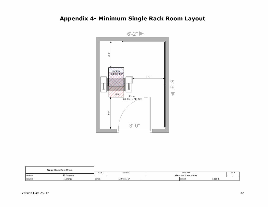
Version Date 2/7/17 32
Appendix 4- Minimum Single Rack Room Layout
8'-3
"
6'-2"
Single Rack Data RoomSIZE FSCM NO DWG NO REV
DRAWN JE Shanks Minimum Clearances 2
ISSUED 1/20/17 SCALE 1/2" = 1'-0" SHEET 1 OF 5
3'-0
"2
'-6
"
Room:
6ft. 2in. X 8ft. 3in.
UPS
3'-0"
3'-0"
Juniper
EX4300-48P
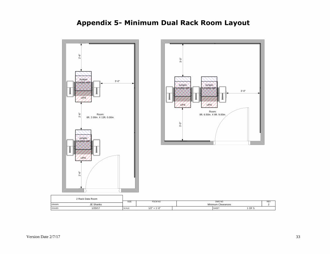
Version Date 2/7/17 33
Appendix 5- Minimum Dual Rack Room Layout
UPS
Juniper
EX4300-48P
UPS
Juniper
EX4300-48P
UPS
Juniper
EX4300-48P
UPS
Juniper
EX4300-48P
2 Rack Data RoomSIZE FSCM NO DWG NO REV
DRAWN JE Shanks Minimum Clearances 2
ISSUED 1/20/17 SCALE 1/2" = 1'-0" SHEET 1 OF 5
Room:
6ft. 2.00in. X 13ft. 0.00in.
Room:
8ft. 6.50in. X 8ft. 9.00in.
3'-0"
3'-0
"3
'-0
"
3'-0"
2'-6
"2
'-6
"2
'-6
"